Electronic Ignition
Gas-Fired
Hot Water
Induced Draft
Boiler
• Installation
•Operation
•Repair Parts
WARNING: Improper installation, adjustment, alteration,
service or maintenance can cause injury or property
damage. Refer to this manual. For assistance or
information consult a qualified installer, service agency
or the gas supplier. Natural gas boilers are not to be
converted to Propanr gas.
Warranty..........................................................2
RulesforSafe Installationand Operation.......3
BoilerRatingsand Capacities.........................4
BeforeYou Start..............................................5
Locatingtheboiler..........................................6
FreshAirforCombustion ................................7
Installation-SystemPiping.................................9
Chimney and VentPipeConnection...............11
HorizontalVenting...........................................14
Gas Supply Piping ........................................ 20
Electrical Wiring/Sequence of Operation ....... 21
Wiring Diagram ............................................. 22
Equipment and Optional Accessories - What
They Do ........................................................ 23
Checking and Adjusting ................................. 27
Maintaining "Your Boiler ................................ 28
Service Hints ................................................. 30
Repair Parts ................................................ 31
SEARS
KENMORE CAST IRON BOILERS
FULL ONE YEAR WARRANTY ON HOT WATER AND GAS STEAM CAST IRON BOILERS
For one (1) year from the date of installation, when this boiler is installed and maintained in accordance
with our instructions. Sears will repair defects in material or workmanship in the boiler, free of charge.
LIMITED 12 YEAR WARRANTY ON STEAM CAST IRON BOILERS
After one (1)year and thoughtwelve(12) yearfrom the dateof installation,Sears willfumish a replacement
heat exchange, ifthe heat exchanger inthe boilerisdefective. YOU PAYFOR LABOR.
LIMITED 20 YEAR WARRANTY ON HOT WATER CAST IRON BOILERS
After one (1) year and through twenty (20) years from the date of installation,Sears willfurnish a
replacement heat exchanger in the boiler isdefected YOU PAY FOR LABOR.
SEARS INSTALLATION WARRANTY
In addition to any warranty extended to you on the Sears merchandise involved, which warranty becomes
effective the date the merchandise is installed, should the workmanship of any Sears arranged installation
prove faulty with one year, Sears will, upon notice from you, cause such faults to be corrected at no
additional cost to you.
FOR WARRANTY SERVICE, SIMPLY CONTACT THE NEAREST SEARS STORE OR
SERVICE CENTER THROUGHOUT THE UNITED STATES. This warranty gives you specific
legal rights, and you may also have other rights which vary from state to state.
IMPORTANT
The following are the responsibilities of the user
and are cover by the Warranty.
1. Filter clearing or replacement.
2. Damage to unit or unsatisfactory operation
due to improper cleaning or use of unit in
corrosive atmosphere.
3. Damage to unit or unsatisfactory operation
due to blown fuses or inadequate or interrupted
electrical protective devices.
4. Damage to unit caused by _e use of components
or other accessoriesnot compatible with the unit:
5. If the unit is removed from the place it was
originally installed, this Warranty becomes void.
6. Damage to the unit caused by accident, abuse,
negligence, misuse, riot,fire, flood,or acts of God.
SEARS ROEBUCK AND COMPANY
D/817WA
Hoffman Estates, IL 60179
2
1. Readthe Owner'sManualfor SaleOperation
carefully. Failure to follow the rules for safe
operation and the instructions can cause a
malfunction of the boiler and result in death,
serious bodily in jury, and/or property damage.
2. Check your local codes and utility requirement
before installation. The installation must be in
accordance with their directives.
3. Before servicing, allow boiler to cool. Always
shut off any electricity and gas to boiler
when working on it. This will prevent any
electrical shocks or burns.
4. Never test for gas leaks with an open flame.
Use soap and check all connections. This
will avoid any possibility of fire or explosion.
5. Be certain your boiler will be using the
correct gas. Overfiring will result in
premature failure of the boiler sections and
cause dangerous operation.
6. Never vent this boiler into an enclosed
space. Always vent to the outside. Never
vent to another room or inside a building.
7. Be sure there is adequate air supply for
complete combustion.
8. Follow a regular service and maintenance
schedule for efficient and safe operation.
TOOLS
Pipe Wrench
Screwdriver
Tin Snips
6 foot tape or folding rule
Hack Saw
LP Torch, if you have copper piping
Pipe cutter and threading tools
(for iron pipe systems)
MATERIALS
Pipe joint compound suitable for natural and propane gas.
Iron or copper pipe for the water lines.
Black pipe for the gas lines.
Miscellaneous fittings.
Solder and flux if you have copper piping.
The following booklets will help you in making the installation:
Electrical Wiring -Available at Sears from the Plumbing, Heating or Electrical Departments at
nominal cost.
American National Standards, Installation of Gas Appliance and Gas Piping, National Fuel
Gas Code ANSIZ223.1 -latest revision.
Obtain from American Gas Association, 1515 Wilson Boulevard, Arlington (Roslyn), VA 22209
3
ASME
RELIEF
VALVE
I
I
I
I
I
LEFT SIDE
DRAII_
VALVE
TEMPERATURE
PRESSURE
IIII
tII
I I
I I I-
I I I
LiMrr & RELAY
CONTROL
Swrm_
IANIFOLD 2
23111
3 <-'--
U _tTCH
[_ _,_" INTERMnTEHT
_ILOT CONTROL
L
FRONT RIGHT SIDE
®
@
®
DESIGN CER11FIED FOR
NA_nJp_,LAND pRGPANE GA_
MODEL
Natural Propane
Gas Gas
229.965520 229.965320
229.965530 229.965330
229.965540 229,965340
229.965550 229.965350
229.965560 229.965369
229.965570 229,965370
AGA Heating
NATURAL AND PROPANE GASES
Net IBR Vent Diameter(INCHES)
Rating
*MBH
31
55
82
109
135
162
Width
A
11
14¼
17%
20¾
24
27¼
To Chimney
(Category I)
4
4
4
4
4
4
No. Input
Sec. *MBH
2 42,5
3 75.0
4 112.5
5 150.0
6 167.5
7225.0
Capacity
+MGB
36
63
94
125
155
186
Horizontal Vent
(Category III)
3
3
3
3
4
4
*MBH = 1,000 Btuh =British Thermal Unit Per Hour
Boilers are equipped foraltitudes upto2,000 feet only: o
U.S.A. Only -For altitudes above 2,000 feet, ratings should be reduced at the rat of4 _ for each 1,000 feet above sea level.
Canada Only -Boilers may be used at highaltitude by using a certified field conversion, kit, resulting in a 10% derate.
+ Heating Capacity based on D.O.E. (Department of Energy}test procedure.
The Ratings marked "Net 1=B=R Ratings" indicate
the amount of remaining heat input that can be
used to heat the radiation or terminal units. The
Net I=B=R Ratings shown are based on an
allowance of 1.15 in accordance with the factors
shown on the I=B=R Standard as published by
The Hydronics Institute.
Selection of boiler size should be based upon
"Net I=B=R Rating" being equal to or greater
than the calculated heat loss of the building.
The manufacturer should be consulted before
selecting a boiler for installations having unusual
piping and pickup requirements. These boilers must
stand on a noncombustible floor. If installed on a
combustible floor, use Combustible Floor Base.
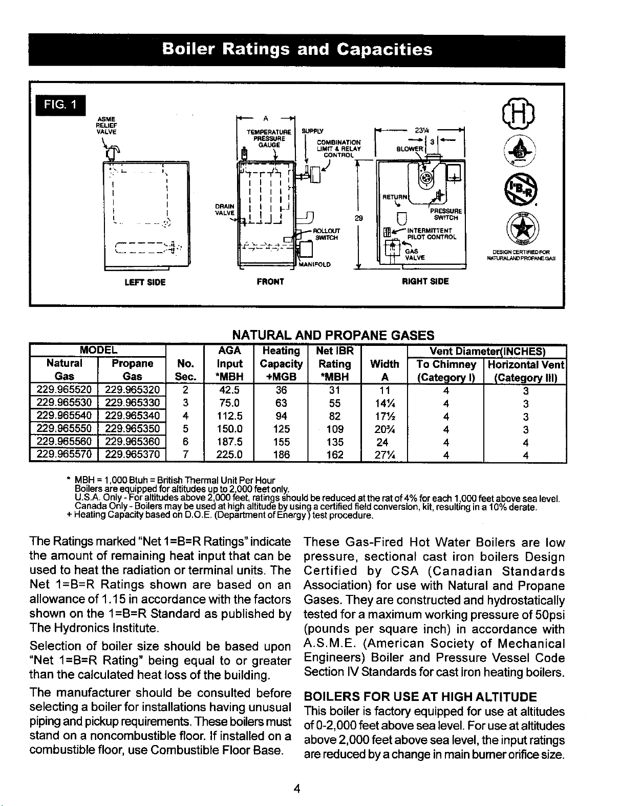
These Gas-Fired Hot Water Boilers are low
pressure, sectional cast iron boilers Design
Certified by CSA (Canadian Standards
Association) for use with Natural and Propane
Gases. They are constructed and hydrostatically
tested for a maximum working pressure of 50psi
(pounds per square inch) in accordance with
A.S.M.E. (American Society of Mechanical
Engineers) Boiler and Pressure Vessel Code
Section IV Standards for cast iron heating boilers.
BOILERS FOR USE AT HIGH ALTITUDE
This boiler is factory equipped for use at altitudes
of 0-2,000 feet above sea level. For use at altitudes
above 2,000 feet above sea level, the input ratings
are reduced by a change in main burner orifice size.
4

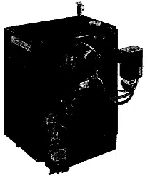
Checktobesureyouhavetherightsizeboilerbefore
startinatheinstallation.Seeratingandcapacitytable
onpreviouspage.Also besurethe newboilerisfor
the type of gas you are using. Check the rating
plate onthe rightside of the boiler.
You must see that the boiler is supplied with the
correcttypeofgas,fresh airfor combustion,and a
suitable electrical supply. Also, the boiler must be
connected to a suitable chimney or horizontal venting
system and an adequate piping system. Finally, a
thermostat, properly located, is needed for control
of the heating system. If you have any doubts as to
the various requirements, check with localauthorities
and obtain professional help where needed. Take
the time to complete all of the steps for SAFE and
PROPER operation of the heating system.
Were required by the authority having jurisdiction,
the installation must conform toAmerican Society
of Mechanical Engineers Safety Code for Controls
and Safety Devices for Automatically Fired
Boilers, No. CSD-I*
The installation must conform to the requirements
of the authority having jurisdiction or, in the
absence of such requirements, to the National
Fuel Gas Code, ANSI Z223. l-latest revision.
The following steps are all necessary for proper
installation and safe operation of your boiler.
1. LOCATING THE BOILER
2. FRESH AIR FOR COMBUSTION
3. SYSTEM PIPING
4. CHIMNEY & VENT PIPE CONNECTION
5. GAS SUPPLY PIPING
6. ELECTRICAL WIRING
7. CHECKING &ADJUSTING
I
KEEP BOILERAREA CLEAN AND FREE FROM COMBUSTIBLE MATERIALS, GASOLINE I
AND OTHER FLAMMABLE VAPORS AND LIQUIDS I
If your boiler is part of a planned heating system,
locate it where shown on your plan. If boiler isto
be part of an existing system, it is usually best to
put itwhere the old one was. !f you plan to change
location, you will need additional materials as well
as an adequate base. The following rules apply:
1. The boiler must be level. Metal shims may be
used under base legs for final leveling.
2. Use a raised base iffloor can become wet or damp.
3. The vent pipe connection should be as short
as possible.
4. Additional clearances for service may exceed
clearances for fire protection. Always comply
with the minimum fire protection clearances
shown on the boiler.An 18 inch clearance should
be maintained on any side where passage is
required to access another side for cleaning,
servicing, inspection or replacement of any part
that may need attention. An 18 inch clearance is
recommended on the control side for servicing.
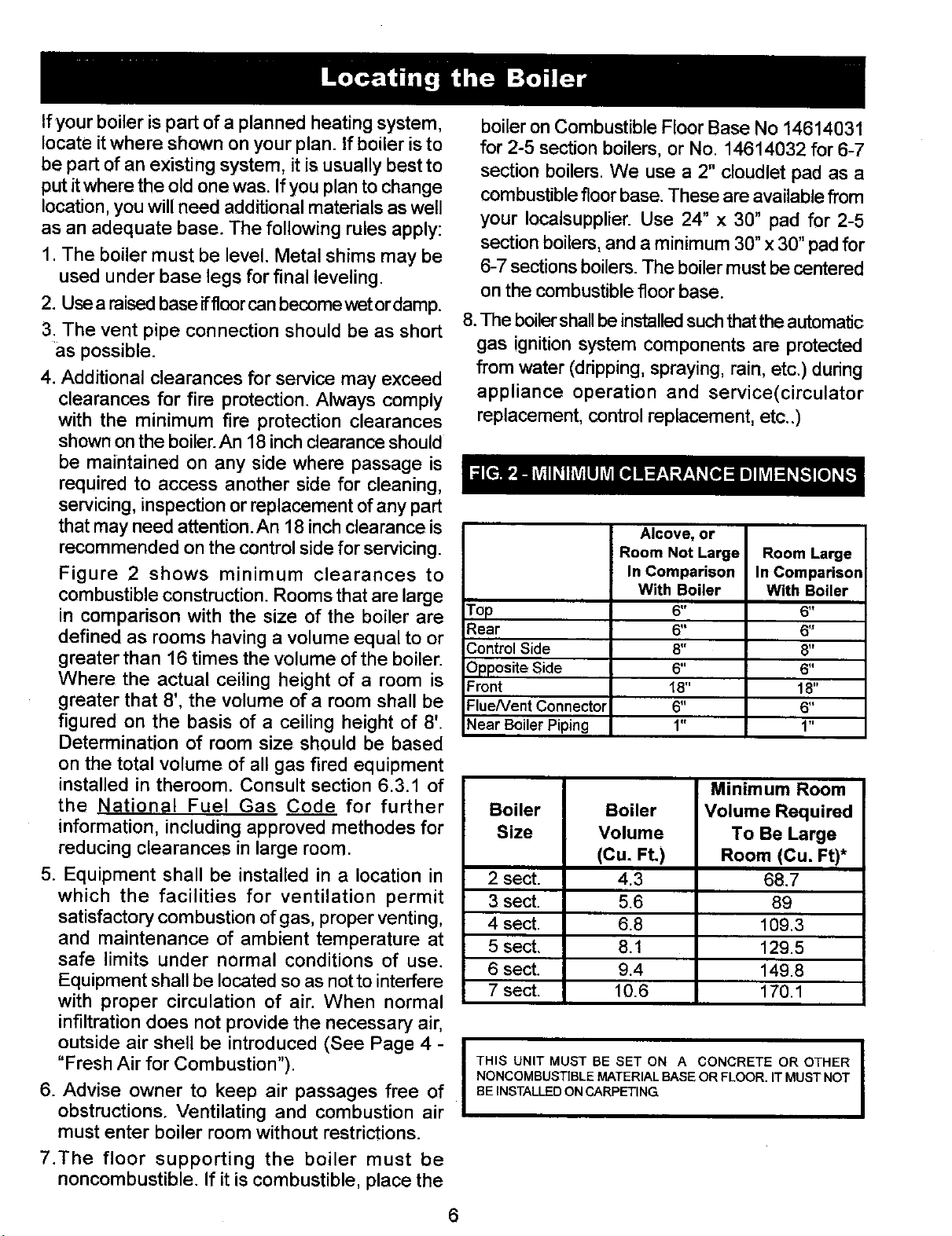
Figure 2 shows minimum clearances to
combustible construction. Rooms that are large
in comparison with the size of the boiler are
defined as rooms having a volume equal to or
greater than 16 times the volume of the boiler.
Where the actual ceiling height of a room is
greater that 8', the volume of a room shall be
figured on the basis of a ceiling height of 8'.
Determination of room size should be based
on the total volume of all gas fired equipment
installed in theroom. Consult section 6.3.1 of
the National Fuel Gas Code for further
information, including approved methodes for
reducing clearances in large room.
5. Equipment shall be installed in a location in
which the facilities for ventilation permit
satisfactory combustion of gas, proper venting,
and maintenance of ambient temperature at
safe limits under normal conditions of use.
Equipment shall be located so as not to interfere
with proper circulation of air. When normal
infiltration does not provide the necessary air,
outside air shell be introduced (See Page 4 -
"Fresh Air for Combustion").
6. Advise owner to keep air passages free of
obstructions. Ventilating and combustion air
must enter boiler room without restrictions.
7.The floor supporting the boiler must be
noncombustible. If it is combustible, place the
boiler on Combustible Floor Base No 14614031
for 2-5 section boilers, or No. 14614032 for 6-7
section boilers. We use a 2" cloudlet pad as a
combustible floor base. These are available from
your Iocalsupplier. Use 24" x 30" pad for 2-5
section boilers, and a minimum 30" x 30" pad for
6-7 sections boilers. The boiler must be centered
on the combustible floor base.
8.The boiler shall be installed such that the automatic
gas ignition system components are protected
from water (dripping, spraying, rain, etc.) during
appliance operation and service(circulator
replacement, control replacement, etc..)
Alcove, or
Room Not Large Room Large
In Comparison In Comparison
With Boiler With Boiler
Top 6" 6"
Rear 6" 6"
Control Side 8" 8"
Opposite Side 6" 6"
Front 18" 18"
FlueNent Connector 6" 6"
Near Boiler Piping 1" 1"
Minimum Room
Boiler Boiler Volume Required
Size Volume To Be Large
(Cu. Ft.) Room (Cu. Ft)*
2 sect. 4.3 68.7
3 sect. 5.6 89
4 sect. 6.8 109.3
5 sect. 8.1 129.5
6 sect. 9.4 149.8
7 sect. 10.6 170.1
ITHIS UNIT MUST BE SET ON ACONCRETE OR OTHER
NONCOMBUSTIBLE MATERIAL BASE OR FLOOR. IT MUST NOT
BE INSTALLED ON CARPETING I
6
I Provision for combustion and ventilation air must be in accordance with Section 5.3, Air for I
Combustion and Ventilation, of the National fuel Gas Code, ANSI Z223.1-latest revision, or I
applicable provisions of the local building codes.
WARNING
Be sure provide enough fresh airfor combustion.
Enough air insures proper combustion and
assures that hazard will develop due to the
lack oxygen.
NOTE
If you use a fireplace or a kitchen or bathroom
exhaust fan, you should install an outside air
intake. These devices will rob the boiler and
water heater of combustion air.
You must provide for enough fresh air to assure
proper combustion. The fire in the boiler uses
oxygen. It must have a continuous supply. The air
in a house contains only enough oxygen to supply
the burner for a short time. Outside air must enter
the house to replace that used bythe burner. Study
following examples I and 2 to determine your fresh
air requirements.
EXAMPLE 1: Boiler Located in Unconfined Space
An unconfned space isdefined as a space whose
volume is not less than 50 cubic feet per 1,000
Btu per hour ofthe total input rating of allappliances
installed in that space.
If your boiler is in an open area (unpartitioned
basement) in a conventional house, the air that
leaks through the cracks around doors and
windows will usually be adequate to provide air
for combustion. The doors should not fit tightly.
Do not caulk the cracks around the windows.
Equipment located in buildings of unusually tight
construction shall be provided with air for
combustion, ventilation, and dilution of flue gases
using the methods described in example 2B or
shall be specially engineered. The authority having
jurisdiction must approve specially engineered
installations.
EXAMPLE 2: Boiler Located in Confined Space
A. All Air from Inside the Building: The confined
space shall be provided with two permanent
openings communicating directly with an additional
room(s) of sufficient volume so that the combined
volume of all spaces meets the criteria for an
unconfined space. The total input of all gas
utilization equipment installed in the 7
combined space shall be considered in making this
determination. Each opening shall have a
minimumfree area of one square inch per 1,000 Btu
per hour of the total input rating of all gas utilization
equipment in the confined space, but not less that
100 square inches. One opening shall be within 12
inches of the top and one within 12 inches of the
bottom of the enclosure. The minimum dimension of
air openings shall not be less than 3 inches.
B. All Air from Outdoors: The confined space
shall communicate with the outdoors in accordance
with methods 1 or 2. The minimum dimension of
air openings shall not be less than 3 in. Where
ducts are used, they shall be of the same cross-
sectional area as the free area of the openings to
which they connect.
1.Two permanent openings, one commencing
within 12 inches of the top, and one commencing
within 12 inches of the bottom, of the enclosure
shall be provided. The openings shall
communicate directly, or by the ducts, with the
outdoors or spaces (crawl or attic) that freely
communicate with the outdoors.
a) Where directly communicating with the
outdoors or where communicating to the
outdoors through vertical ducts, each
opening shall have a minimum free area of
1 sq. in, per 4000 Btu per hour oftotal input
rating of all equipment in the enclosure.
(See Figure 3A.)
b) Where communicating with the outdoors
throughhorizontal ducts, each opening shall
have a minimum free area of 1 area ofsq.
in. per 2000 Btu per hour of total rating of
all equipment in the enclosure. (See Fig.3B.)
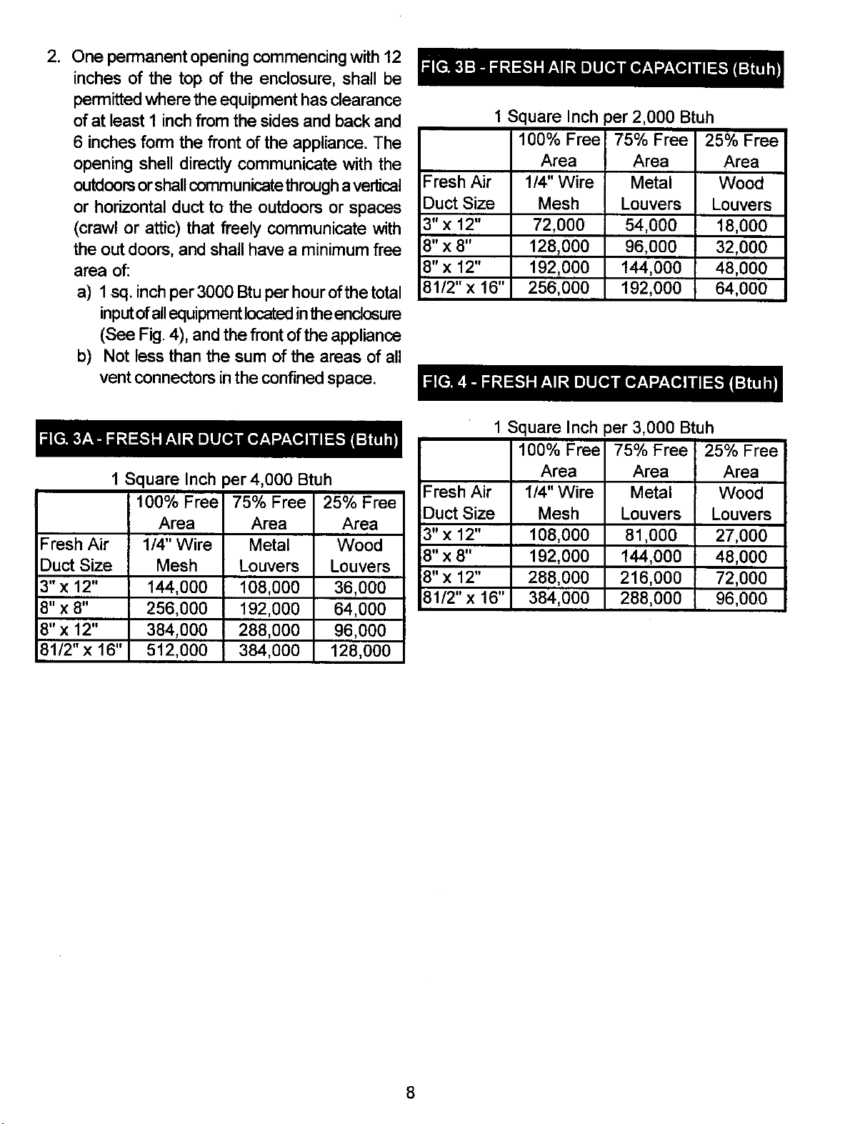
2, Onepermanentopeningcommencingwith 12
inches of the top of the enclosure, shall be
permitted where the equipment has clearance
of at least 1 inch from the sides and back and
6 inches form the front of the appliance. The
opening shell directly communicate with the
outdoorsor shallcommunicate through avertical
or horizontal duct to the outdoors or spaces
(crawl or attic) that freely communicate with
the outdoors, and shall have a minimum free
area of:
a) 1 sq. inch per3000 Btu per hour ofthe total
inputofallequipment locatedinthe enclosure
(See Fig. 4), and the front of the appliance
b) Not less than the sum of the areas of all
vent connectors in the confined space.
1 Square Inch
100% Free
Area
Fresh Air 1/4, Wire
Duct Size Mesh
3" x 12" 72,000
8" x 8" 128 000
8"x 12" 192,000
81/2"x 16" 256,000
)er 2,000 Btuh
75% Free 25% Free
Area Area
Metal Wood
Louvers Louvers
54,000 18,000
96,000 32,000
144,000 48,000
192,000 64,000
1Square Inch )er 4,000 Btuh
100% Free 75% Free 25% Free
Area Area Area
Fresh Air 1/4" Wire Metal Wood
Duct Size Mesh Louvers Louvers
3"x 12" 144,000 108,000 36,000
8" x 8" 256,000 192,000 64,000
8" x 12" 384,000 288 000 96,000
81/2" x 16" 512,000 384,000 128,000
1Square Inch
100% Free
Area
Fresh Air 1/4" Wire
Duct Size Mesh
3" x 12" 108,000
8" x 8" 192,000
8" x 12" 288,000
81/2"x 16" 384,000
oer 3,000 Btuh
75% Free 25% Free
Area Area
Metal Wood
Louvers Louvers
81,000 27,000
144,000 48,000
216,000 72,000
288,000 96,000
8

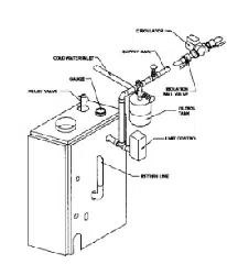
1. Place boiler in the selected location (as near
chimney as possible). Your boiler is shipped
assembled.Youneedonlyto installthecirculator,
ball valves the relief valve with a drain line to
carryanywater to adrain, andthe drain valve.
2. Install ReliefValveon 3/4"pipenippleintapped
openinginthe leftend section. Connecta drain
line of the same pipe size (3/4" to carry any
water away to a drain. No shutoff of any
descriptionshall be placed betweenthe safety
reliefvalveand theboiler,orondischargepipes
betweensuchsafetyvalvesandtheatmosphere.
Installationofthesafetyreliefvalveshallconform
to the requirements of theANSI/ASME Boiler
and PressureVessel Code,Section IV.
3. Install Drain Valve on lower left side of boiler
as marked.
4. Connect Supply and Return Lines to boiler.
The connections may require certain
additional fittings and parts, as shown on
diagram (Figs. 5 and 6).
Ifyou are installing an entire newheatingsystem,
first install all of your radiation units (panels,
radiatorsorcabinets) and theSupplyand Return
Mains- then make the connections atthe boiler.
Inconnecting the cold water supply to the water
valve, make sure that a clean water supply is
available. When the water supply isfrom a well
or pump, a sand strainer should be installed at
the pump.
A hotwater boiler installed above radiation level
must beequipped with a lowwater cutoff device.
Aperiodic inspection is necessary,as isflushing
of float type devices, per manufacturers specific
instructions.
When boiler is used in connection with
refrigeration systems it shall be installed sothat
the chilled medium is piped in parallel with the
heating boiler with appropriate valves to prevent
the chilled medium from entering the heating
boiler (Fig. 7).
When this boiler isconnected to heating coils located
in air handling units where they may be exposed to
refrigerated air circulation, the piping system shall
be equipped with flow control valves or other
automatic means to prevent gravity circulation of
the boiler water during the cooling cycle.
LOW DESIGN WATER TEMPERATURE
SYSTEMS (BELOW 140 ° F)
If the boiler is to be used in a heating system
where design water temperatures below 140 °
F are desired (e.g. radiant floor heating), a 3-
way or 4-way mixing valve or suitable alternative
is required to prevent low temperature return
water from entering the boiler. Follow the mixing
valve manufacturers installation instructions.The
minimum design return water temperature to
the boiler to prevent condensation in the boiler
and venting is 120 ° F The minimum high limit
setting is 140 ° F.
9

VALVES A & B - OPEN FOR HEATING; CLOSED FOR COOLING
VALVES C & D - CLOSED FOR HEATING; OPEN FOR COOLING
TO SYSTEM
B
10
I For boilers for connection to gas vents or chimneys, vent installations shell be in accordance
with Part 7, Venting of Equipment, of the National Fuel Gas Code, ANSI Z223.l-latest issue
and applicable provisions of the local building codes.
CHECK YOUR CHIMNEY
This is a very important part of your heating system.
Itmust be clean, the right size, properly constructed
and in GOOD CONDITION. No boiler can function
properly with a bad chimney.
1. Use local codes for installation or National Fuel
Gas Code Z223.1-1atest issue. In Canada,
follow CSA 13149.1 or .2 Installation Codes. It
is very important to properly size the venting
system for induced draft appliances. Consult
the Vent Sizing Tables, in the National Fuel
Gas Code ANSI Z223.1-1atest revision for
correct sizing information In Canada, consult
the Vent Sizing Tables, Amendment #1 to CSA-
13149.1 and .2 Installation Codes.
2. The boiler's induced draft blower has a 3" outlet.
A 3" X 4" increaser fitting isincluded in the parts
bag. Locate the increaser fitting on the outlet
of the induced draft blower, and secure gastight
with a bead of the furnished silicone sealant.
The increaser fitting is required on this boiler
for Category I venting, and 4" is the minimum
permissible vent diameter. This does not imply
that the vent connector is intended to be 4"
diameter pipe. The vent connector shall be sized
according to the appropriate venting tables in
the National Fuel Gas Code or the Canadian
Installation Codes, and may be required to be
larger than 4" diameter.
The boiler installation for chimney venting
is not complete unless the 3" x 4" increaser
fitting is located and secured.
3. These are high efficiency boilers with a low stack
or exhaust temperature.
4. Ifventing into a masonry chimney without a liner,
line the chimney from top to bottom with either:
a, listed Type B vent pipe
b. listed fexible vent liner
c. poured ceramic liner.
5. Outside chimneys should not be used unless
they are either:
a. enclosed in a chase, or
b. lined with Type B vent pipe, or listed flexible
vent liner, or other certifEEI chimney lining system.
6. The vent connector from the boiler to the
chimney should run as directly as possible with
as few elbows as possible.
7. Where possible, it is recommended to common
vent the water heater and boiler. Consult the
appropriate Vent Sizing Tables in either the
National Fuel Gas Code, or the Canadian
Installation Codes for specific requirements
of multiple appliance venting.
8. If the boiler is the only appliance connected to
the vent, Type B vent pipe is recommended
for the vent connector.
9. Slope pipe up from boiler to chimney not less
than 1/4" per foot.
10. End of vent pipe must be flush with the inside
face of the chimney flue. Use a sealed-in
thimble for the chimney connection.
11. The sections of vent pipe should be fastened
with sheet metal screws to make the piping
rigid. Use stovepipe wires to support the pipe
from above.
12. Do not connect to fireplace flue.
13. Do not install a damper on this boiler.
MINIMUM VENT PIPE CLEARANCE
if the vent pipe must go through a crawl space,
Type B vent pipe should be used. Where vent
pipe passes through a combustible wall or
partition, use a ventilated metal thimble. The
thimble should be 4 inches larger in diameter than
the vent pipe.
11

If boiler is installed with single wall vent, it must
have a 6" clearance between its surface and any
combustible material. Anew Type B gas vent
orflexible liner must be installed in accordance
with the instructions furnished with the vent.
Maintain clearances as specified for the vent pipe.
Check the vent pipe to see if it is firestopped
where it goes through the floor or ceiling. It
should have an approved vent cap with
clearances from the roof as shown in Fig. 8. If
clearances are less than shown in Fig. 8, have
the vent checked by local authorities.
For boilers for connection to gas vents or
chimneys, vent installations shall be in
accordance with Part 7, Venting Equipment,
of the national Fuel Gas Code, ANSi Z223.1-
latest issue and applicable provisions of the
local building codes. In Canada, follow CSA
13149.1 or .2 Installation Codes.
Vent connectors sewing appliances vented
by natural draft shall not be connected into
any portion of mechanical draft systems
operating under positive pressure.
m
"_- LINE R
10'_'_I Ni i
' "-J THE VENT PIPE MUST BE AT
LEAST 2 FEET HIGHER THAN
ANY PART OF THE ROOF
WITHIN A [0 FT RADIUS
OFTHE VENT,
SHEET NETAL
FIRESTO_
0 0
12
REMOVING EXISTING BOILER FROM
COMMON VENTING SYSTEM
When an existing boiler isremoved from a common
venting system, the common venting system is
likely to be too large for proper venting of the
appliances remaining connected to it.
At the time of removal of an existing boiler, the
following steps shall be followed with each
appliance remaining connected to the common
venting system placed in operation, while the other
appliance remaining connected to the common
venting system are not in operation.
1. Seal any unused openings in the common
venting system.
2. Visually inspect the venting system for proper
size and horizontal pitch and determine there is
no blockage or restriction, leakage, corrosion
and other deficiencies which could cause an
unsafe condition.
3. Insofar as is practical, close all building doors
and windows and all doors between the space
in which the appliances remaining connected to
the common venting system are located and
other spaces of the building. Turn on clothes
dryers and any appliance not connected to the
common venting system. Turn on any exhaust
fans, such as range hoods and bathroom
exhausts, so they will operate at maximum
speed. Do not operate a summer exhaust fan,
Close fireplace dampers.
4. Place in operation the appliance being inspected.
Follow the lighting instructions. Adjust thermostat
so appliance will operate continuously.
5. Test for spillage at the hood relief opening after
5 minutes of main burner operation. Use the
flame of a match or candle, or smoke from a
cigarette, cigar or pipe.
6. After ithas been determined that each appliance
remaining connected to the common venting
system properly vents when tested as outlined
above, return doors, windows, exhaust fans,
fireplace dampers and any other gas-burning
appliance to their previous conditions of use.
7. Any improper operation of the common venting
system should be corrected so the installation
conforms with the National Fuel Gas Code,
ANSI Z223.1-1atest issue. When resizing any
portion of the common venting system, the
common venting system should be resized to
approach the minimum size as determined using
the appropriate tables in Part 11 in the National
Fuel Gas Code, ANSI Z223.1-1atest issue. In
Canada, follow CSA B149.1 or.2 Installation
Codes.
NOTE
It is recommended that existing gas vents be
checked to be sure they meet local codes.
13
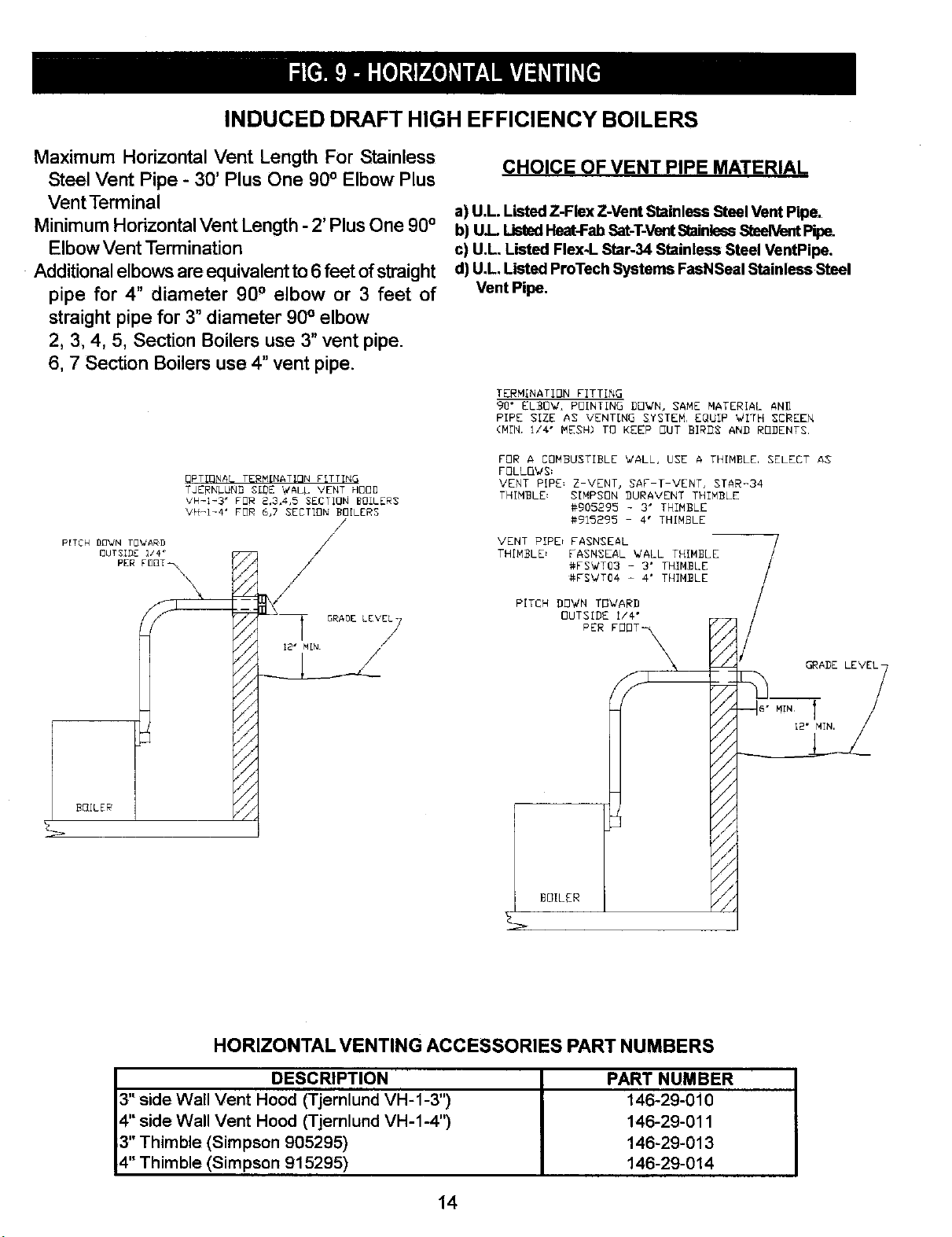
INDUCED DRAFT HIGH EFFICIENCY BOILERS
Maximum Horizontal Vent Length For Stainless
Steel Vent Pipe -30' Plus One 90°Elbow Plus
VentTerminal
Minimum HorizontalVent Length - 2' PlusOne 90°
ElbowVent Termination
Additional elbowsare equivalentto6 feet ofstraight
pipe for 4" diameter 90° elbow or 3 feet of
straight pipe for 3° diameter 90° elbow
2, 3, 4, 5, Section Boilers use 3"vent pipe.
6, 7 Section Boilers use 4" vent pipe.
OPTIONAL TERMINATION F[TTTNG
TJERNLUNB SIDE WALL VENT HOOD
VH-I_3" FOR 2,3,4,5 SECTION BOILERS
VH-I-4' FOR 6,7 SECTION BOILERS
PER FBBT_\
CHOICE OF VENT PIPE MATERIAL
a) U.L. Listed Z-Flex Z-Vent Stainless Steel Vent Pipe.
b) UL ListedHeat-FabSat-T-VentSlainlessSteelVentPipe.
c) U.L Listed Flex-L Star-34 Stainless Steel VentPipe.
d) U.L Listed ProTech Systems FssNSeal Stainless st_eel
Vent Pipe.
TERMINATION FITTING
90" EL_OW, POINT;NO DOWN, SAME MATERIAL AN_
PIPE SIZE AS VENT[NO SYSTEM, EQUIP WITH SCREEN
(M[N. I/4" MESH) TO KEEP OUT BI_S ANB RODENTS,
FOR A COMBUSTIBLE WALL, USE A THIMBLE, SELECT Ag
FOLLOWS=
VENT RIPE; Z-VENT, SAF-T-VENT, STAR-34
THIMBLE: SIMPSON DURAVENT THIMBLE
#905295 - 3" THIMBLE
#915_95 -4" THIMBLE
VENT PIPE_ FASNSE_L
TH[MBLD FASNSEAL WALL THIMBLE
#FSVT03 - 3" TH[MBLE
#FS_T04 - 4" THTMBLE
PITCH DOWN TOWARD
OUTSIDE I/4"
PER FOD___
HORIZONTAL VENTING ACCESSORIES PART NUMBERS
DESCRIPTION
3" side Wall Vent Hood (Tjernlund VH-1-3")
4" side Wall Vent Hood (Tjernlund VH-1-4")
3" Thimble (Simpson 905295)
4" Thimble (Simpson 915295)
PART NUMBER
146-29-010
146-29-011
146-29-013
146-29-014
14
1. These boilers may be vented horizontally as
shown in Fig. 9. The vent pipe is pitchedlml_l
from the boiler to the vent termination. Do not
connect other appliances to this vent.
2. Vent Pipe Material:
a) UL Listed Z-Flex Z-Vent stainless steel vent
pipe from boiler to vent termination,
-or-
b) UL Listed Heat-FabSaf-T-Vent stainless steel
vent pipe from boiler to vent termination,
-or-
c) UL Listed Flex-L StaR-34 stainless steel vent
pipe from boiler to vent termination,
-or-
d) UL Listed ProTech FasNSeal stainless steel
vent pipe from boiler to vent termination.
3. Clearance to Combustible Materials:
For stainless steel vent pipe maintain 6" minimum
air space clearance to combustible materials.
4. Vent Pipe Size:
a) 2, 3, 4 and 5 section boilers use 3" vent pipe
connected directly to the outlet of the induced
draft blower.
b) 6 and 7 section boilers use 4" vent pipe,
starting with a 3" to 4" stainless steel vent
pipe transition that is connected directly to
the outlet of the induced draft blower. Do not
use 3" vent pipe on 6 or7 section boilers.
5. Vent Pipe Length:
a) For stainless steel vent pipe, the maximum
horizontal vent length is 30 feet plus one 90°
elbow plus termination fitting.
b) Minimum horizontal vent length for all vent
materials is 2 feet plus one 90 °elbow plus
termination fitting.
c) For additional elbows reduce the maximum
vent length as shown:
3"- 90° elbow -reduce vent ler_glh3 feetpereach 3''
elbow,
4" - 90 °elbow - reduce vent length 6 feet per
each 4" elbow.
Example: 6 section boiler requires 3 elbows
plus the termination fitting. This means 2
additional 4" elbows will be used, at 6 feet
per elbow. This is equivalent to 12 feet of
pipe (2 x 6 =12), therefore maximum vent
length is now 18 feet (30 -12 =18). 15
6. Vent Termination Fitting:
For all vent pipe materials, you may use either:
a) a 90°elbow pointing down, fitted with a
minimum 1/4" mesh screen to keep out
rodents and birds. The elbow shall be of the
same material and size as vent pipe. The
elbow exit should be at least 6" away from
exterior wall as shown in Figure 9.
-or-
b) Tjernlund VH-1 Series side wall vent hood.
For 2, 3, 4, 5 section boilers use VH-1-3", For
6, 7 section boilers use VH-1-4".
7. Vent Pipe Termination Location:
a) When venting through combustible walls,
combustible clearances must be considered.
The VH-1 Side wall vent hood provides both
the outside vent termination and a double
wall pipe for passing through a combustible
wall up to 8" thick (VH-1-4") or 9" thick (VH-
1-3"). The hole in the wall must be 6%" square
for 3" vent pipe and 7 1/2" square for 4" vent
pipe, in order to insert the VH-1 side wall
vent hood. The VH-1 may also be used in
noncombustible walls.
b) If the 90' elbow is the termination fitting of
choice, then the single wall pipe willbe passing
through the side wall. For combustible walls,
a UL listed thimble shall be used where the
single wall pipe passes through the wall. For
combustible walls using Z-Vent, Sat-T-Vent,
or StaR-34 vent pipe, use the following:
3" vent pipe - use Simpson's Duravent
#905295 3" thimble or equivalent
4" vent pipe - use Simpson's Duravent
#915295 4" thimble or equivalent Maximum
wall thickness with this thimble is 7 inches.
For combustible walls using ProTech
FasNSeal where the single wall vent pipe must
pass through the side wall, a UL Listed
FasNSeal wall thimble shall be used as
follows:
3" FasNSeal vent pipe - use 3" FasNSeal Wall
Thimble #FSWT03 4" FasNSeal vent pipe - use
4" FasNSeal Wall Thimble #FSWT04
The thimble is adjustable for different wall
thickness, with a maximum wall thickness of
7 inches. Seal the thimble along the outside
edge of the plate with caulk or silicone and
fasten to the wall with screws or nails.
c) For single wall pipe through non-combustible
walls, the hole through the wall need only be
large enough to maintain the pitch of the vent
pipe, and provide proper sealing. Athimble is
not required for single wall pipe passing
through noncombustible walls.
d) The venting system shall terminate at least 3
feet above any forced air inlet located within
10 feet. The venting system shall terminate
at least 4feet below, 4 feet horizontally from,
or 1 foot above any door, window, or gravity
air inlet into any building. The bottom of the
vent shall be located at least 12 inches above
grade. Termination of the vent shall be not
less than 7 feet above an adjacent public
walkway. The vent terminal shall not be
installed closer than 3 feet from the inside
corner of an L shaped structure. Termination
of the vent should be kept at least 3 feet away
from vegetation. The venting system shall
terminate at least 4 feet horizontally from, and
in no case above or below, unless a 4 foot
horizontal distance is maintained, from electric
meters, gas meters, regulators, and relief
equipment,
e) The venting system shall terminate at least 4
feet below any eave, soffit, or roof overhang.
f) The venting system shall not terminate
underneath any deck, patio, or similar
structure.
g) Put vent on a wall away from the prevailing
winter wind. Locate or guard the vent to prevent
accidental contact with people or pets.
h) Terminate the vent above normal snowline.
Avoid locations where snow may drift and block
the vent. Ice or snow may cause the boiler to
shut down if the vent becomes obstructed.
i) Under certain conditions, flue gas will condense,
forming moisture. In such cases, steps should
be taken to prevent building materials at the
vent terminal from being damaged by exhaust
of flue gas.
8. Joining and Sealing the Vent Pipe:
The vent pipe needs to be both watertight and
gastight. Seal a!l joints and seams as follows:
A. For Z-Flex Z-Vent stainless steel vent pipe
use a hightemperature red silicone sealant rated
for 500°F. The outside ofthe male end and inside
ofthe female end ofthe pipe must be cleaned with
brake cleaner before applying silicone bead, 16
For 3"vent pipe runs begin with the male end of
the vent pipe over the boilers induced draft
blower outlet. For 4" vent pipe runs begin with a
6" length of 3" Z-Vent (#02SVEPxx0306) over
the boiler's induced draft blower outlet, to which
an even bead of high temperature silicone sealant
should be applied. Then connect the 3" Z-Vent
to a Z-Vent 3" to 4" reducer (#02SVERxx0403).
Then continue the 4" Z-Vent pipe run by
connecting the 4" male end of the Z-Vent to the
reducer. (A locking band may be used around
this joint for additional support.) Then following
the sealing instructions, push the 4" male end of
the Z-Vent over the 4" increaser fitting. When
using the Tjernlund VH-1 vent hood, the female
end (flared end) of the vent pipe will be
connected to the termination hood. The male
end of the vent hood must be crimped before
pushing the Z-Vent over the vent hood's
connecting pipe. Before the pipes are joined,
apply a 1/4" bead of silicone one inch from the
end of themale end. Then push the pipes
together as far as they will go making sure any
seams are aligned and oriented upward. Now
apply another bead of silicone around this joint
and smooth out. Then use a Z-Flex locking band
around the center of the joint.
Z-Flex Z-Vent Size Lockina Band Part #
3" #02SVSLBX03
4" #02SVSLBX04
1) Apply the high temperature silicone
approximately one inch from the end, around
the male end of the pipe in an even 1t4" bead.
2) Pipes can now be pushed together as far
as they will go. The seams on pipe should
be aligned and oriented upward in all
horizontal appliances. Apply another bead
of silicone around this joint and smooth
out.3) Slide locking band over center ofjoint
and tighten gear clamps. Make sure locking
band is centered on joint.
4) Check alljoints and seams for gas tightness.
5) Horizontal venting shall have a slope not
less than 1/4" (6.4mm) every 12 inches
(305mm) downward away from the boiler
to prevent collection of condensate
throughout the assembly.
6)Allow the sealant to cure for 24 hours before
operating the appliance.

B. For Heat-Fab Saf-T-Vent stainless steel
vent pipe use a high temperature red silicone
sealant rated for 500"F The outside of the
male end and inside of the female end of the
pipe must be cleaned before applying the
silicone bead. For 3" vent pipe runs, the male
end of the vent pipe which goes over the outlet
of the boiler's induced draft blower must be
crimped. The vent pipe should be crimped
as minimal as possible to provide a tight fit
over the outlet. After crimping is completed
follow the instructions for applying silicone
sealant. For 4" vent pipe runs, begin with a
Saf-T-Vent 3" to 4" increaser fitting
(#7374GC) over the boiler's induced draft
blower outlet, to which an even bead of high
temperature silicone sealant should be
applied. Then continue the 4" Saf-T-Vent pipe
run by connecting the 4" male end of the Sal-
T-Vent to the increaser. (A locking band may
be used around this joint for additional
support.) The vent flow must bein the
direction indicated on the vent pipe. When
using the Tjernlund VH-1 vent hood, the female
end (flared end) of the vent pipe will be
connected to the termination hood. Apply high
temperature silicone in an even 1/4" bead
approximately 1/4" to 3/8" from the end of
the vent hood's connecting vent pipe. Also,
run a similar size bead of silicone sealant
down the seam weld of the vent pipe. Then
push the female end over the vent hood's
connecting vent pipe.
1) Apply the high temperature silicone around
the male end of the pipe (without the tabs)
in an even W' bead. Silicone bead should be
approximately 1/4" to 3/8" from the end of
the male end. Also, run a similar size bead
of silicone sealant down the seam weld at
the end of each joint.
2) Pipes can now be pushed together as far as
theywill go. The seams onthe vent pipeshould
be aligned and oriented upward in all
horizontal appliances. With a moistened finger
or fiat tool, spread any sealant that squeezes
out around the circumference of the joint.
3) Attach the sections together with the
locking rings and tabs (except at the blower
outlet where no locking ring exists.) 17
C=
Inspect the joint to ensure that flue gases
will not leak. If necessary apply additional
sealant around the joint.
4) Horizontal venting shall have a slope not
less than 114" (6.4mm) every 12 inches
(305mm) downward away from the boiler
to prevent collection of condensate
throughout the assembly.
5) Allow the sealant to cure for 24 hours
before operating the appliance.
For Flex-L StaR-34 stainless steel vent
pipe use a high temperature red silicone
sealant rated for 500°F. Before applying
silicone, the outside of the male end and
inside of the female end of the pipe must be
cleaned using a cleaner, such as methyl ethyl
ketone (MEK) or naptha. For 3" vent pipe
runs, begin with the male end of the vent pipe
over the boiler's induced draft blower outlet.
For4" vent pipe runs begin with a StaR-34 3"
to 4" increaser fitting (#SR10304) over the
boiler's induced draft blower outlet. For both
3" and 4" vent pipe runs, apply a bead of
silicone sealant around the blower outlet and
around the inside of the male end of vent
pipe going over the blower's outlet. When
using the Tjemlund VH-1 vent hood, the female
end (flared end) of the vent pipe will be
connected to the termination hood. Apply high
temperature silicone in an even %4" bead
approximately 1/4"frem the end of the vent
hood's connecting vent pipe. Also, run a similar
size bead of silicone sealant down the seam
weld of the vent pipe. Then push the female
end over the vent hood's connecting vent pipe.
Now fillin the channel inlet with silicone sealant.
Do not try to insert the joiner band, instead
fasten the vent pipe to the vent hood's pipe
with a steel gear clamp.
1) Apply the high temperature silicone around
the male end of the pipe in an even 114"
bead. Silicone bead should be approximately
1/4" from the end of the male end. Also, run
a similar size bead of silicone sealant down
the seam weld at the end of each joint.
2) The seams on the vent pipe should be
aligned and oriented upward in all horizontal
vent pipe runs.
3) insert the male end of one into the female end
of the other. Push the pipe together so the
female end rests up against the stop bead of
the male end.
4) Insert a StaR-Joiner Band into the inlet of the
beaded channel. Feed the Joiner Band in so it
makes itsway aroundthe pipe,back to the channel
inlet and it overlaps itself by about lf2".
5) Cut the excess Joiner Band so it lays fiat in
the beaded channel. Fillthe inlet of the beaded
channel with high temperature silicone. Smooth
out the silicone over the channel inlet and the
silicone between the female end and the stop
bead of the male end.
6) Horizontal venting shall have a slope not less
than 1/4" (6.4mm) every 12 inches (305ram)
downward away from the boiler to prevent
collection of condensate throughoutthe assembly.
7) Allow the sealant to cure for 24 hours before
operating the appliance.
D. For ProTech Systems FasNSeal stainless
steel vent pipe no cleaning fluid is required.
For 3" vent pipe runs on 2, 3, 4 and 5 section
boilers begin by locating the FasNSeal Ametek
Adapter (part #FSAMETEK) over the boiler's
induced draft blower. Continue the vent pipe run
with 3" FasNSeal vent pipe. For 6 and 7 section
boilers begin by locating the FasNSeal Ametek
Adapter (part #FSAMETEK) over the boiler's
induced draft blower. Then connect a
FasNSeal 3" to 4" increaser (part #FS341 ) to
the 3" adapter outlet. Continue the vent pipe
run with 4" FasNSeal vent pipe. Other than
the Ametek Adapter and increaser fitting, DO
NOT use 3" vent pipe on 6 or7 section boilers.
FasNSeal vent pipe is joined and sealed by
the use of an internal sealing gasket and a
locking band on the female end of each vent
pipe. All components should be examined for
possible shipping damage prior to installation.
Align all vent pipe seams and orient upward in
all horizontal applications. Adjustable vent
lengths are available for 4" diameter vent
piping. For 3" diameter vent piping, square cut
male end atthe desired length. For2, 3, 4 and
5 section boilers using the VH-1-3" vent hood,
connect the FasNSeal Vent to the VH-1-3" vent
hood using FasNSeal Adapter #FSC-DUN-3.
This adapter has no internal sealing gasket.
18
To attach the adapter to the vent hood, crimp
the 3" vent hood pipe, apply a 1/4" bead of high
temperature red silicone sealant around the
outside of the vent hood's crimped connecting
pipe and a similar bead of high temperature
silicone around the inside of the FasNSeal
adapter. After pressing the two pipes together
and tightening the locking band, finish creating a
complete seal by filling the FasNSeal adapter's
notched hole with high temperature silicone.
For 6 and 7 section boilers using the VH-1 -4" vent
hood, an adapter is not required. The 4" FasNSeal
vent pipe connects directly to the VH-1-4" vent
hood, and isjoined and sealed bythe intemal gasket
and locking band.
To join and seal the FasNSeal vent pipe:
1) Insert male end into female section.
2) Push the units together as far as possible.
3) Firmly tighten locking band with a nut driver.
4) DO NOT penetrate the FasNSeal vent pipe
with fasteners.
5) Horizontalventingshallhave a slope of notlessthan
1/4" (6.4mm),every 12 inches (305ram) downward
away from the boiler to prevent the collection of
condensate throughout the assembly.
9, Support Spacing:
Do not restrict thermal expansion movement
of the vent, The vent pipe must expand and
contract freely with temperature change. Each
run of vent piping shall be supported as
follows:
a) Z-Flex stainless steel vent piping requires
a loose fitting metal strap or similar support
at each joint at amaximum of 4 feet
between supports.
b) Heat-Fab stainless steel vent piping requires
a support for every 6 feet of horizontal piping
run. The support must be secured using at
least #10 fasteners to a solid material (solid
masonry or woodframing or blocking.) Do
not fasten to drywall sheathing using hollow
wall anchors. Each support will be 1 1/2 inch
lower than the previous support when
spaced 6 feet apart.
c) Flex-L stainless steel vent piping requires
a loose fitting metal strap or similar support
at each joint at a maximum of 4 feet
between supports.
d) ProTech stainless steel vent piping requires
one loose fitting FasNSeal support strap
(#FSSH) for every 6' of horizontal vent.
10. If the horizontal vent must go th rough a crawl
space or other unheated space, the cool
temperatures will likely cause the flue gases
to continuously condense inside the vent pipe.
Do not insulate the vent pipe. It must be visible
for monthly inspection. Insure that the vent
pipe is properly pitched away from the boiler,
with no low spots, so that condensate in the
vent willdrain away from the boiler. An insulated
enclosure or chase, with access for inspection
and servicing of the vent, may be required to
prevent freezing of liquid condensate. Consult
the vent pipe manufacturer's instructions for
specific guidelines.
11. At the beginning of each heating season and
monthly during the heating season, check all
vent pipes and the vent terminal to make sure
there are no obstructions. Periodically clean
the screen in the vent terminal.
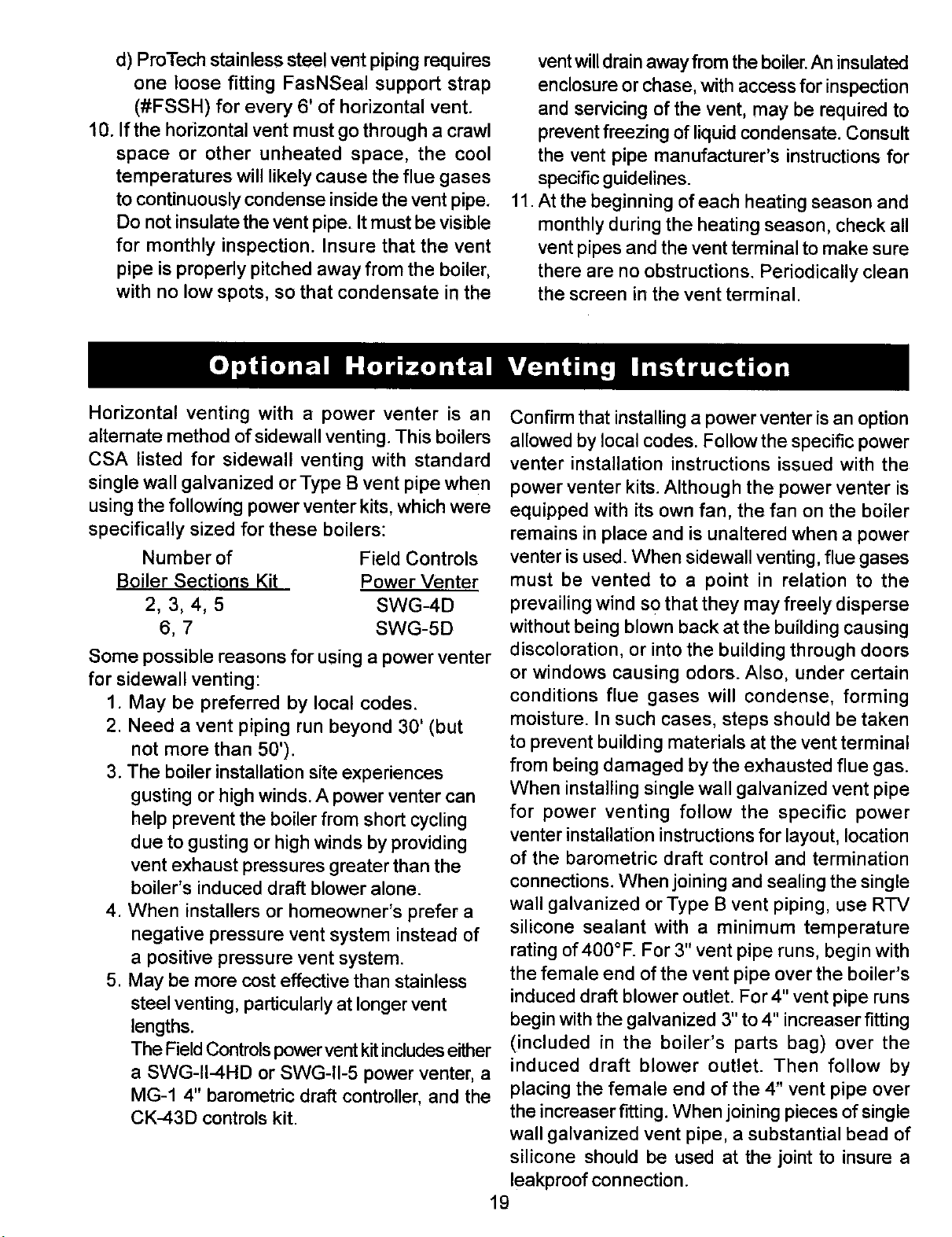
Horizontal venting with a power venter is an
alternate method of sidewall venting. This boilers
CSA listed for sidewall venting with standard
single wall galvanized or Type B vent pipe when
using the following power venter kits, which were
specifically sized for these boilers:
Number of
Boiler Sections Kit
2,3,4,5
6,7
Field Controls
Power Venter
SWG-4D
SWG-5D
Some possible reasons for using a power venter
for sidewall venting:
1. May be preferred by local codes.
2. Need avent piping run beyond 30' (but
not more than 50').
3. The boiler installation site experiences
gusting or high winds. A power venter can
help prevent the boiler from short cycling
due to gusting or high winds by providing
vent exhaust pressures greater than the
boiler's induced draft blower alone.
4. When installers or homeowner's prefer a
negative pressure vent system instead of
a positive pressure vent system.
5. May be more cost effective than stainless
steel venting, particularly at longer vent
lengths.
The Field Controls power vent kit includes either
a SWG-II-4HD or SWG-II-5 power venter, a
MG-1 4" barometric draft controller, and the
CK-43D controls kit.
Confirm that installing a power venter is an option
allowed by local codes. Follow the specific power
venter installation instructions issued with the
power venter kits. Although the power venter is
equipped with its own fan, the fan on the boiler
remains in place and is unaltered when apower
venter is used. When sidewall venting, flue gases
must be vented to a point in relation to the
prevailing wind so that they may freely disperse
without being blown back at the building causing
discoloration, or into the building through doors
or windows causing odors. Also, under certain
conditions flue gases will condense, forming
moisture. In such cases, steps should be taken
to prevent building materials at the vent terminal
from being damaged by the exhausted flue gas.
When installing single wall galvanized vent pipe
for power venting follow the specific power
venter installation instructions for layout, location
of the barometric draft control and termination
connections. When joining and sealing the single
wall galvanized or Type B vent piping, use R-IV
silicone sealant with a minimum temperature
rating of 400°F. For 3" vent pipe runs, begin with
the female end of the vent pipe over the boiler's
induced draft blower outlet. For 4" vent pipe runs
begin with the galvanized 3" to 4" increaser fitting
(included in the boiler's parts bag) over the
induced draft blower outlet. Then follow by
placing the female end of the 4" vent pipe over
the increaser fitting. When joining pieces of single
wall galvanized vent pipe, a substantial bead of
silicone should be used at the joint to insure a
leakproof connection.
19
CHECKGAS SUPPLY
The gaspipe toyour boiler must bethe corrects'[zefor the
lengthofthe runand forthetotal BTU perhour inputofall
gas utilization equipment connected to it.See F_J.10for
the proper size. Be sure your gas linecomplies with local
codes and gas company requirements.
The boiler and its individual shutoff vaive must be
disconnected from the gas supply piping system during
any pressure testing of thatsystem at test pressures in
excess of 1/2 psig (3.5 kPa).
The boiler must be isolated from the gas supply piping
system bydosing itsindividualmanualshutoffvak_during
any pressure testing of the gas supply piping system at
test pressures equal to or less than 1/2 psig (3.5 kPa).
CONNECTING THE GAS PIPING
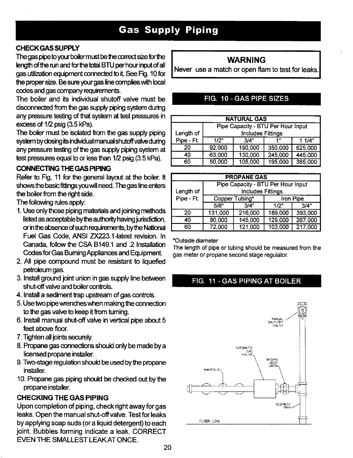
Refer to Fig, 11 for the general layout at the boiler. It
showsthe basic f-_ngs you will need. The gas lineenters
the boiler from the right side.
following rules apply:
1.Use only those piping materials and joining metheds
listed as acceptable bythe authority having jurisd_on,
or inthe absence ofsuch requirements, bythe Nationel
Fuel Gas Code, ANSI ZX223.1-1atest revision. In
Canada, follow the CSA B149.1 and .2 Installation
Codes for Gas Burning Appliances and Equipment
2. All pipe compound must be resistant to liquefied
pe'm3leumgas.
3. Install ground joint union in gas supply line between
shut-off valve and boiler controls.
4. Install a sediment Imp upskeam of gas controls.
5. Use two pipewrenches when making the conneclJon
to the gas valve to keep itfrom turning.
6. Install manual shut-off valve in ver'dcal pipe about 5
feet above floor.
7. rKjhten alljoints securely.
8. Propane gas conneclions should only be made by a
licensed propane installer.
9.Two-stage regulation should be used bythe propane
installer.
10. Propane gas piping should be checked out by the
propane installer.
CHECKING THE GAS PIPING
Upon completion of piping, check right away for gas
leaks. Open the manual shut-off valve. Test for leaks
by applying soap suds (or a liquid detergent) to each
joint. Bubbles forming indicate a leak. CORRECT
EVEN THE SMALLEST LEAK AT ONCE. 2O
I WARNING I
Never use a match or open flam to test for leaks.
Length of
Pipe - Ft.
20
40
60
NATURAL GAS
Pipe Capacity -BTU Per Hour Input
Includes Fittings
1/2" 3/4" 1" 1 1/4"
92,000 190,000 350,000 625,000
63,000 130,000 245,000 445,000
50,000 105,000 195,000 365,000
PROPANE GAS
Pipe Capacity - BTU Per Hour Input
Length of Includes Fittings
Pipe - Ft. Copper Tubin@* Iron Pipe
5/8" 3/4" 1/2" 3/4!'
20 131,000 216,000 189,000 393,000
40 90,000 145,000 129,000 267,000
60 72,000 121,000 103,000 217,000
*Outside diameter
The length of pipe or tubing should be measured from the
gas meter or propane second stage regulator,
FLOOR LINE
All electrical work must conform to local codes as
well asthe National Electrical Code, ANSI/NFPA-70,
latest revision. InCanada, eleclncalwiring shall comply
with the Canadian Electrical Code, CSA-C22.1.
ELECTRIC POWER SUPPLY
Run a separate 120 volt circuit from a separate
overcurrent protective device in the electrical service
entrance panel. This should be a 15 ampere circuit.
Locate ashut-off switch atthe boiler. Itmust be tumed
off during any maintenance. Connect 120 volt power
supply to aquastat terminals L1 (HOT) and L2.
The boiler, when installed, must be electrically
grounded in accordance with the requirements of
the authority having jurisdiction or, in the absence of
such requirements, with the National Electiical Code,
ANSI/NFPA No. 70-latest revision. Run a 14 gauge
or heavier copper wire from the boiler to a grounded
connection in the service panel ora properly driven
and electrically grounded ground rod.
I WARNING I
Tum offelectric power at fuse box before making any
linevoltage connections. Follow localelectricalcodes.
INSTALL YOUR THERMOSTAT
The thermostatlocation has an important effect on the
operationofyourboilersystem.BESURETO FOLLOWTHE
INSTRUCTIONSINCLUDEDWITHYOURTHERMOSTAT
Locatethethermostataboutfivefeet abovetheflooronan
insidewall.It maybe mounteddirectlyon thewall orona
verticallymountedoutletbox.Itshouldbesensingaverage
morntemperature,soavoidthefollowing:
DEAD SPOTS:
Behind doors
Corners and alcoves
HOTSPOTS:
Concealedpipes
Fireplace
TV sets
Radios
Lamps
Directsunlight
Kitchens
COLDSPOTS:
Concealedpipesorducts
Stairwells-dra_
Doors-drafts
Unheatedroomonothersideofwall
Setheatantidpatorat.2amps.24voltthermostatconnects
toaquastatterminalsTandT
1.Thermostat calls for heat, powering the 1K relay
coil and closing contacts 1 K1 and 1 K2.
2. Circulator pump is powered through terminals
Cl and C2.3. Induced dra_ blower and AT140C
transformer primary are powered through
terminals B1 and B2.
4. When blower gets up to speed and blower
suction pressure reaches pressure switch
setpoint, pressure switch contacts close sending
24 volts to $8600 intermittent pilot control from
AT140C transformer secondary.
5. Pilot gas valve opens and spark initiates to light
pilot burner. 6. When pilot flame is proven, spark
drops out.
7. Main gas valve opens and pilot burner ignites
main burners.
8. If boiler water temperature reaches high limit
setpoint,highlimitcontacts B-Ropen, cut'dngpower
to blower and $8600 intermittent pilot control. 21
Bumere extinguish and blower stops. Circulator
pump continues to run as long as the thermostat
continues to call for heat. When boiler water
temperature drops past the high limit setpoint
and through the differential, high limit contacts
B-R close, repeating steps 3-7.
9. If venting system becomes blocked, blower
suction pressure will drop below the pressure
switch setpoint, opening the pressure switch
contacts and cutting power to the $8600
intermittent pilotcontrol. Bumere willextinguish,
but blower will remain powered as long as the
thermostat continues to call for heat. Ifventing
system clears, steps 4-7 will repeat.
10. Thermostat is satisfied, ending call for heat:
Relay coil 1 K is de-energized, opening 1K1
and 1K2 contacts. Burners extinguish. Blower
and circulator pump stop.
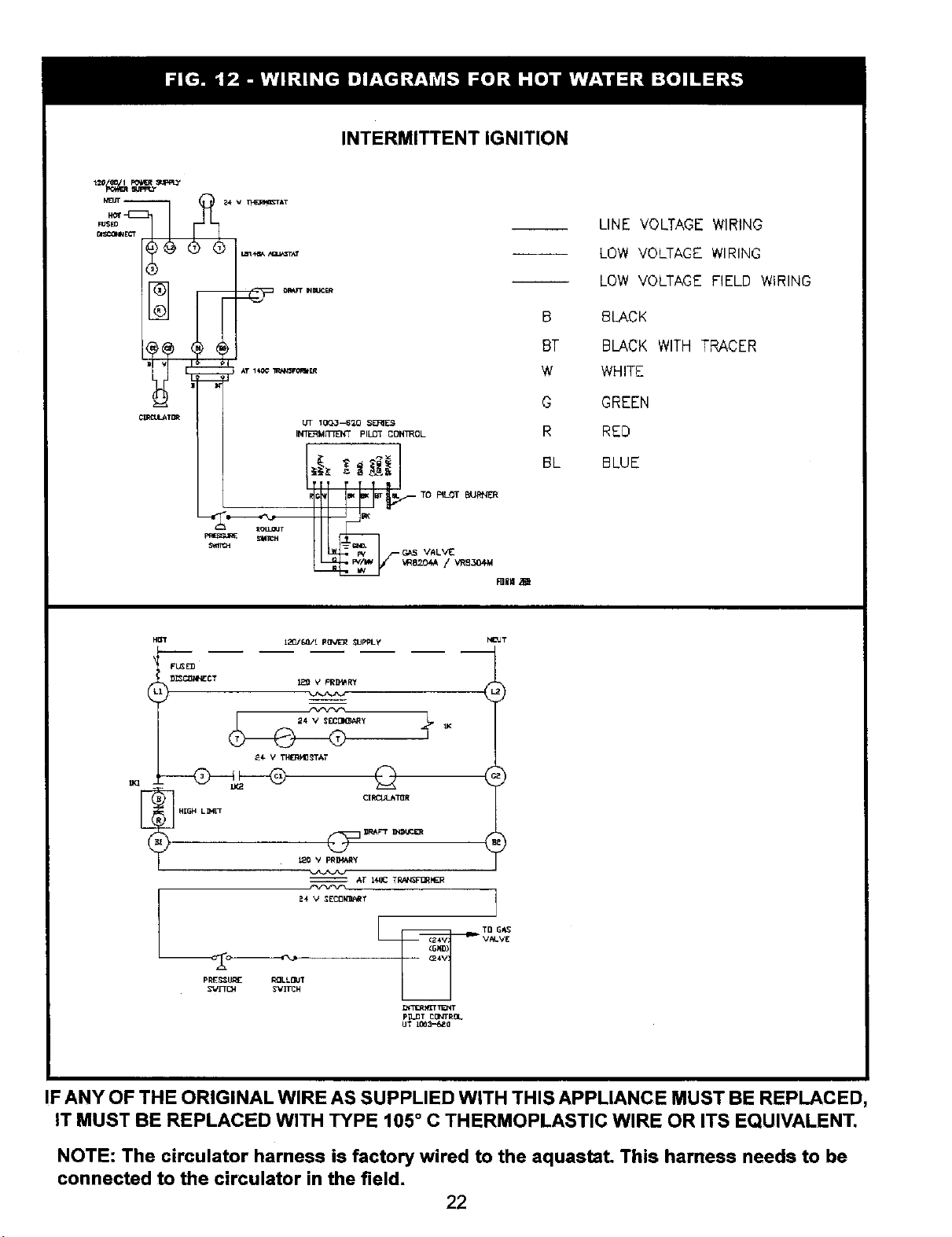
INTERMITTENT IGNITION
C_T_
_ _Fr IImJCER
AT 1tC_ ll_k_vO_l ER
Lrf 1OQ3--6_O _ERIE_
INTERM_'_" pILOT COK_OL
TIf IP ! T-'o Lo
mllH ,_
B
BT
W
O
R
BL
LINE VOLTAGE WIRING
LOW VOLTAGE WIRING
LOW VOLTAGE FIELD WIRING
BLACK
BLACK WITH TRACER
WHITE
GREEN
RED
BLUE
H_
FL_
k
_,l_ VTH_J_g_TAT
HIN4 LINI_
Al" H+gCTll/l,l_l]tI,ER
TO Gl_
V#L.V[
pI_E,_+_I1_ RaLLI_CJT
_+i'll_t ll,iT _ T
pil,_ T _lll_ltllk
IF ANY OF THE ORIGINAL WIRE AS SUPPLIED WITH THIS APPLIANCE MUST BE REPLACED,
IT MUST BE REPLACED WITH TYPE 105 ° C THERMOPLASTIC WIRE OR ITS EQUIVALENT.
NOTE: The circulator harness is factory wired to the aquastat. This harness needs to be
connected to the circulator in the field. 22

RELIEF VALVE
You must have arelief valve on your boiler. Water
expands as it is heated. If there is no place for the
water to expand into, water pressure will build up
inside the boiler and system. Should this happen,
the Relief Valve will automatically open at a pre-
determined pressure. This will relieve the strain on
the boiler and system. Run a pipe from the relief
valve outlet (pipe must be same size as outlet and
the open end must not be threaded) to an open
drain, tub or sink, or other suitable drainage point
not subject to freezing. Failure to do so may cause
water damage or injury should relief valve release.
EXPANSION TANK (Optional)
In a properly assembled system, the expanding
waterflowsintoanExpansion Tank,Thistankshould
be of the correct size.
The tank is filled with air. As the water expands it
compresses the air in the tank to form an air
pressure cushion. This "spring-like" cushion serves
to maintain correct operating water pressure
regardless of water temperature. This assures a
"full measure" of water, even in the highest radiation
unit of the system. It also prevents blowing off of
the relief valve.
The air in the tank in the beginning (with system
filled with cold water) is sufficient for proper
operation. The tank also serves as a trap for
excess air in the system. The air would cause
gurgling in the pipes and inefficient circulation in
the radiators if left in the system.
It is possible for a tank to become "waterlogged"
(filled with water). It can also become overfilled
with air. This can happen after filling the system
with new water. Fittings provided on the tank and
in the line to the tank are for bleeding off excess
water or air.
When installing this tank, it is important: 1) That
the tank be higher than the boiler top. 2) That the
pipe to the tank continuously rises up to the tank
(so that air can "bubble" up to it).
DIAPHRAGM TYPE EXPANSION
TANK (Optional)
The Diaphragm Type Expansion Tank (EX-TROL)
takes the place of the conventional expansion tank.
Carefully read the instructions packed with your
EX-TROL Tank Assembly.
The EX-TROL Tank comes to you with a 10-12
pounds per square inch air charge. This is the same
as the pressure produced in the system by the
automatic fill valve. When the system is first filled,
the EX-TROL Tank will contain little or no water.
As the water is heated its pressure increases. It
expands into the EX-TROL Tank, compressing the
air in the tank. This compressed air cushion permits
the water in the system to expand as the
temperature changes.
AIR ELIMINATING FI'n'ING (AIR PURGER)
(Optional)
An Air Purger is used to remove excess air from
the system. It is installed in the supply line. It will
help to eliminate air from the water before it
reaches the radiators and bleed off this air.
MAIN AIR VENT FOR DOWN FLOW
SYSTEMS OR DIAPHRAGM TYPE
EXPANSIONTANK(Optional)
Before a system is filled with water, there is air
in the pipes and radiation units. Some of it will
be trapped asthe system is filled. It is possible
to eliminate most of this air through the air vents
on the radiation units. AMain Air Vent will speed
and simplify this. It should be installed on the
highest point in the main when all radiation is
below top of boiler:
AUTOMATICFILLVALVE (Optional)
For safe, efficient operation, a hot water system
must be filled with water. Adding new water, when
needed can be done manually (by use of a hand
valve in the water supply line). This requires regular
attention to the system's needs. An Automatic Fill
Valve accomplishes this without attention. It is
installed in the Supply Line on hot water boilers
only. The Valve operates through water pressure
differentials. It does not require an electrical
connection.
DRAIN VALVE
This manual valve provides a means of draining all
water from the boiler and system. It is often installed
in the 3/4°tapping at the bottom of the left boiler
section. Or it can be installed in a tee where the
return line enters the boiler.
23
WATER TEMPERATURE CONTROL
The water temperature limit control in the relay is
adjustable and may be set as necessary. It may
be set as lowas 140° F, oras highas 240°F This
depends on the type and amount of radiation
involvedand weather conditions.
CIRCULATING PUMP
Every Forced Hot-Water System requires a
Circulating Pump. Aseparate pump or zone valve is
required for each Zone, if you have a two or more
Zone System. This pump must have the capacity to
provide the circulation required by your system.
The pump does not come pre-installed on the boiler.
It must be connected to the circulator harness in
the field according to the pump manufacturer's
instructions and the wiring diagrams in this manual.
BLOWER (DRAFT INDUCER)
The blower provides a means for pulling air through
the boiler and exhausting the flue gasses into the
vent system. The blower shuts off when the burners
are not firing. This keeps heat in the house rather
than having it go up the chimney.
PRESSURE SWITCH
The air pressure switch works on a negative
pressure. When the blower comes on the air
pressure sw'rtchoperatesthe intermittentpilotand
gas valve. The air pressure switch is factory set
and will only work when the blower operates
properly.It will not allow the boilerto come on if
the blowerdoes notgenerate enough pressure or
ifthe venting system is blocked.
FACTORY PRESSURE SWITCH SETPOINT:
-0.4" wc. for 2-5 section boilers.
-0.5" w.c. for 6-7 section boilers.
ROLLOUT SWITCH
(FLAME ROLLOUT SAFETY SHUTOFF)
The rollout switch is a temperature-sensitive fuse
link device. It is located on the boiler base just
outside the fire box. In the event of heat exchanger
flueway blockage causing flame to roll out of the
fire box, the fuse will blow, shutting down the flow
of gas to the main burners. The fuse does not
change in appearance when blown,
If the rellout switch blows, it must be replaced with
an exact replacement. Check heat exchanger
flueways for blockage when restoring system to
operating condition. Do not operate system without
a rollout switch.
24
HOWA HOT-WATER SYSTEM OPERATES
Your entireheating system (boiler, piping and radialJon
units) is filled with water. As the water in the boiler is
heated, itis pumped from the top of the boilerthrough
the supply main to the radiation units. The cooler
water in them flows back through the return.main to
the boiler• This provides positive and rapid response
to the thermostat.
FILLING SYSTEM WITH WATER
Close the Air Vents on all radiation units. Open
the Valves to these units. Make sure the boiler
and Expansion Tank Drain Cocks are closed• The
Air Bleed Screw on the tank Drain Fitting should
be closed. Open the valve in the line from the
boiler to the expansion tank (see page 15 for
additional information). Open the water inlet to
your boiler and leave itopen. Start with the lowest
radiation unit. Open the air vent on this unit. When
all the air has escaped and water starts to flow
from the vent, close it. Go to the next radiation
unit, and repeat this process. Repeat until you
have covered every radiation unit in the system
(ending up at the highest unit in the system). If
your units have automatic vents, this manual
venting is unnecessary but it will speed up the
proper filling of your system.
Ifyour system is a closed expansion tank system,
you may have an Automatic Fill Valve. You may
leave it open to refill the system automatically as
needed. Check the temperature-pressure gauge.
Note the position of the hand indicating pressure.
This should be between 10 and 15 Ibs. Any
lowering of this movable hand below 10 Ibs. will
indicate loss of water due to leakage. The
automatic fill valve should compensate for this.
Instructions are packaged with the valve.
WARNING-Never run water into a hot empty boiler. I
•This appliance isequipped with an ignitiondevice
which automatically lights the burner. Do not
attempt to light the burner by hand.
WARNING: If you do not follow these
instructions exactly, fire or explosion may
result with property damage, personal injury,
or loss of life.
2. BEFORE OPERATING smell all around the
appliance area for gas. Be sure to smell next to
the floor because some gas is heavier than air
and will settle on the floor.
WARNING: IF YOU SMELL GAS:
Do not attempt to operate any appliance, do
not touch any electrical switch, do not use
the phone.
Leave the building immediately and call your
gas supplier.
If your gas supplier cannot be reached, call
the fire department.
3. WARNING: When turning or depressing the
gas control knob, use only your hand to push
down or turn the knob. Never use tools. If
the knob will not operate by hand, the control
must be replaced by a qualified service
technician. Force or attempted repair may
result in a fire or explosion.
4. WARNING: If any part of this appliance has
been under water, do not operate.
Immediately call a qualified service technician
to inspect the appliance and to replace any
part of the gas control system which has been
under water.
25
1. Set the thermostat to lowest setting.
2. Turn off all electric power to the appliance.
3. This appliance is equipped with an ignition device
which automatically lights the burner. Do not
attempt to light the burner by hand.
4. Remove burner access panel.
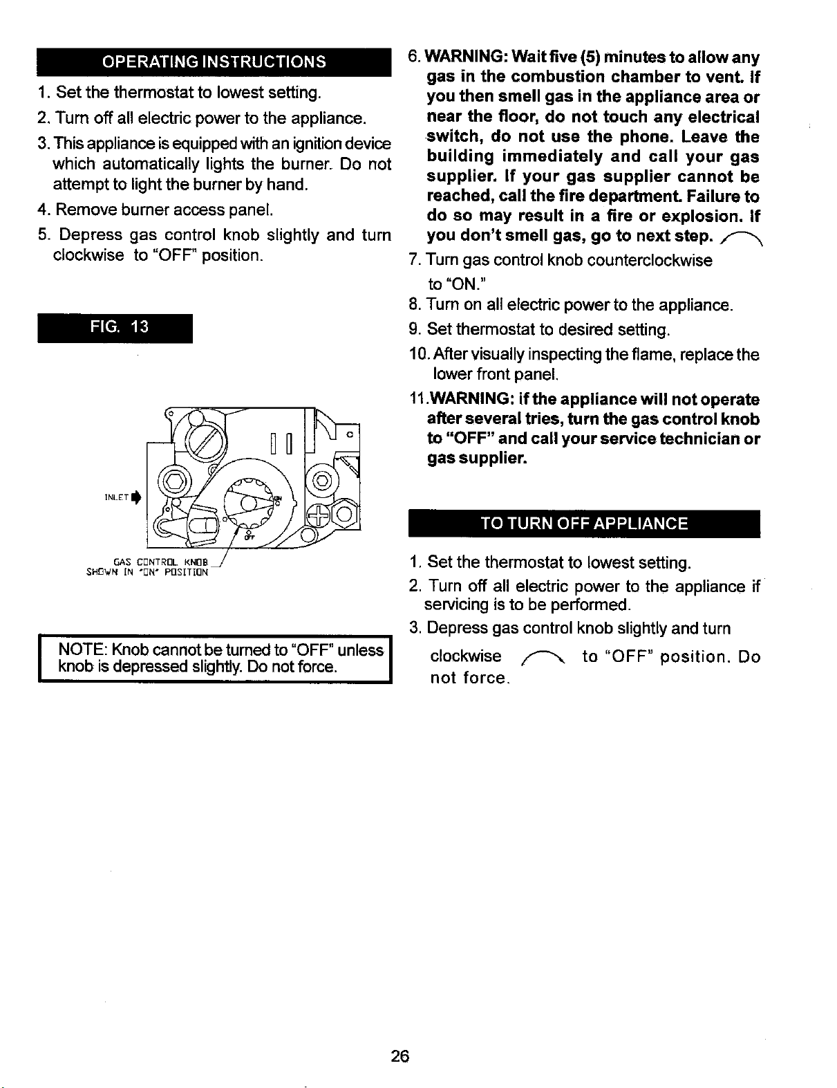
5. Depress gas control knob slightly and turn
clockwise to "OFF" position.
GAS CBNTRnL KNOB_
SHB_VN IN "[_N" Pf]SITION
IOTE: Knob cannot be turned to "OFF" unless I
knob isdepressed slightly. Do not force. I
6. WARNING: Wait five (5) minutes to allow any
gas in the combustion chamber to vent. If
you then smell gas in the appliance area or
near the floor, do not touch any electrical
switch, do not use the phone. Leave the
building immediately and call your gas
supplier. If your gas supplier cannot be
reached, call the fire department. Failure to
do so may result in a fire or explosion. If
you don't smell gas, go to next step.
7, Turn gas control knob counterclockwise
to "ON."
8. Turn on all electric power to the appliance.
9. Set thermostat to desired setting.
10.After visually inspecting the flame, replace the
lower front panel,
11.WARNING: if the appliance will not operate
after several tries, turn the gas control knob
to "OFF" and call your service technician or
gas supplier.
1, Set the thermostat to lowest setting.
2. Turn off all electric power to the appliance if
servicing is to be performed.
3. Depress gas control knob slightly and turn
clockwise F-_, to "OFF" position. Do
not force.
26

GAS VALVE SAFETY SHUTDOWN TEST
With main burners firing,disconnect the ign_on cable
from the intermittent pilotcontrol box. The gas valve
should shut off the main burners. TURN OFF
ELECTRIC POWER to boiler before reconnecting
ignition cable, to prevent electric shock,
ADJUST PILOT BURNER
1. Remove screw cover over pilot adjusting screw.
2. Insert small screwdriver and adjustflame as needed.
(Fig. 14). Turn screw counterclockwise to increase
flame, clockwise to decrease (Fig. 15).
3, Replace screw cover over pilot adjusting screw.
MAIN BURNER(S)
The main burners do not require primary air
adjustment and are not equipped with primary air
shutters. Main burner flames should form sharp
blue inner cones in a softer blue outer mantel, with
no yellow. Puffs of air from blowing on the flame or
stamping on the floor will cause the flames to turn
orange momentarily. This is not unusual. Remain
still when observing the main burner flames. If the
flame appearance is not correct, check main burner
orifices and the burner throat and flame ports for
dust and lint obstruction. It may be necessary to
remove the rolloutshield to observe the main burner
flames. Replace rollout shield after observation.
Refer to Figure 16.
ADJUST LIMIT CONTROLS
Instructionsforeachcontrolareincludedwiththecontrols
RECOMMENDEDBOILERWATERTEMPERATURES I
Tvoe of Heatino Unit Limit Control Seffinq I
StandingRadiators.............................................180 F I
BaseboardandConvectorRadiators..............200°E I
These settings can be changed after you have had
some idea howthe system works. Example: Ifyour
system does notgive quite enough heat invery cold
weather, you can raise the limit setting to 220 ° E
ADJUST THERMOSTAT HEATANTICIPATOR
INSTRUCTIONS FOR THE FINALADJUSTMENT
OF THE THERMOSTATARE PACKAGED WITH
THE THERMOSTAT. Set Heat anticipator at .2.
Check thermostat operation. When set above
temperature indicated on the thermometer, boiler
burners should ignite. Make certain the thermostat
turns offthe boilerwhen room temperature reaches
the selected setting and starts the boiler operating
when room temperature falls afew degrees.
Aftersetting limit control to desired setting, check 27
to see if it shuts off the gas supply to the
burners.Turn your thermostat up to call for heat
and let your boiler run until the temperature of the
water reaches the limit setting. The gas valve should
shut off and the circulator keep running until the
thermostat is satisfied, or the water cools enough
to restart the burners through the limit control.
To check the operation of the contacts in the
pressure switch, disconnect the rubber tubing
(located between the blower and the pressure
switch) from the pressure switch, while the boiler
is operating. The burners should extinguish and
the blower should keep running. When the tubing
is reconnected to the pressure switch, the ignition
sequence should begin, resulting in ignition of the
main burners.
Finally, set the thermostat for the desired
temperature. Special conditions in your home and
the location of the thermostat will govem this setting.
Safe lighting and other performance criteria were
met with the gas manifold and control assembly
provided on the boiler when the boiler underwent
tests specified in ANSI Z21.13-latest revision.
_ on sensor
/
PRESSURE REGULATOR
AOJUSTMENT
(UNDER C_P SCREW)
\
INLET
PRESSURE
TAP \
INLET _ I_QUTLET
BURNERS
A visual check of the pilotand main burner flames
should be made at least once each year, preferably
at the beginning of the heating season. See page
17 and Figures 14, 15 and 16.
RELIEF VALVE
This valve should open automatically if the system
pressure exceeds the pressure rating (usually 30
psi) of the relief valve. Should it ever fail to open
under this condition, shutdown your system. Drain
the system until system pressure is reduced below
the relief valve pressure rating. If valve discharge
occurs, or ifvalve fails to open as described above,
contact an authorized contractor or qualified service
technician to replace the relief valve and inspect the
heating system to determine the cause, as this may
indicate an equipment malfunction.
This valve should be tested every month during
periods of boiler operation, and at the beginning
and end of any extended non-service period. Prior
to testing, make certain discharge pipe is properly
connected to valve outlet and arranged so as to
contain and safely dispose of boiler discharge. Test
at normal system operating pressure. Hold the trip
lever fully open for at least five seconds in order to
flush free any sediment that may lodge on the valve
seat. Then permit the valve to snap shut.
EXPANSION TANK
As previously noted, this tank may become
waterlogged, or may receive an excess of air.
Frequent automatic opening of the relief valve
indicates water logging. A high boiler temperature
accompanied by unusually low radiation unit
temperature (and "knocking") indicates excess air
in tank.To correct either condition, close the valve
between the boiler and the tank. Drain the tank until
it is empty. Check all the tank plugs and fittings.
"13ghtenasnecessary. Open the valve between the
boiler and tank, Water will riseto the normal height in
the tank ifyou have an automatic fill valve (otherwise,
manually refill the system).
BOILER FLUE PASSAGES
Under normaloperatingconditions,withtheburners
properly adjusted, it should not be necessary to
clean the boiler flue gas passages. However, to
assuretrouble-freeoperation,we recommendthat
you have the flue passages, burner adjustment,
and operation ofthe controlschecked once each
year by a competent Service Technician.
Before the start of each season
(or whenever system has been shut down for some
time) recheck the whole system for leaks.., and
recheck the boiler and vent pipe for leaks. Replace
or patch any boiler seals that are faulty.
VENT PIPE
The venting of this unit is very important and
the piping should be checked at least once a
month. If the vent piping shows any sign of
leaking, replace it immediately.
WATER SYSTEM
If system isto remain outof service during freez-
ingweather, always drain itcompletely (water left
in to freeze will crack the pipes andtor boiler).
28
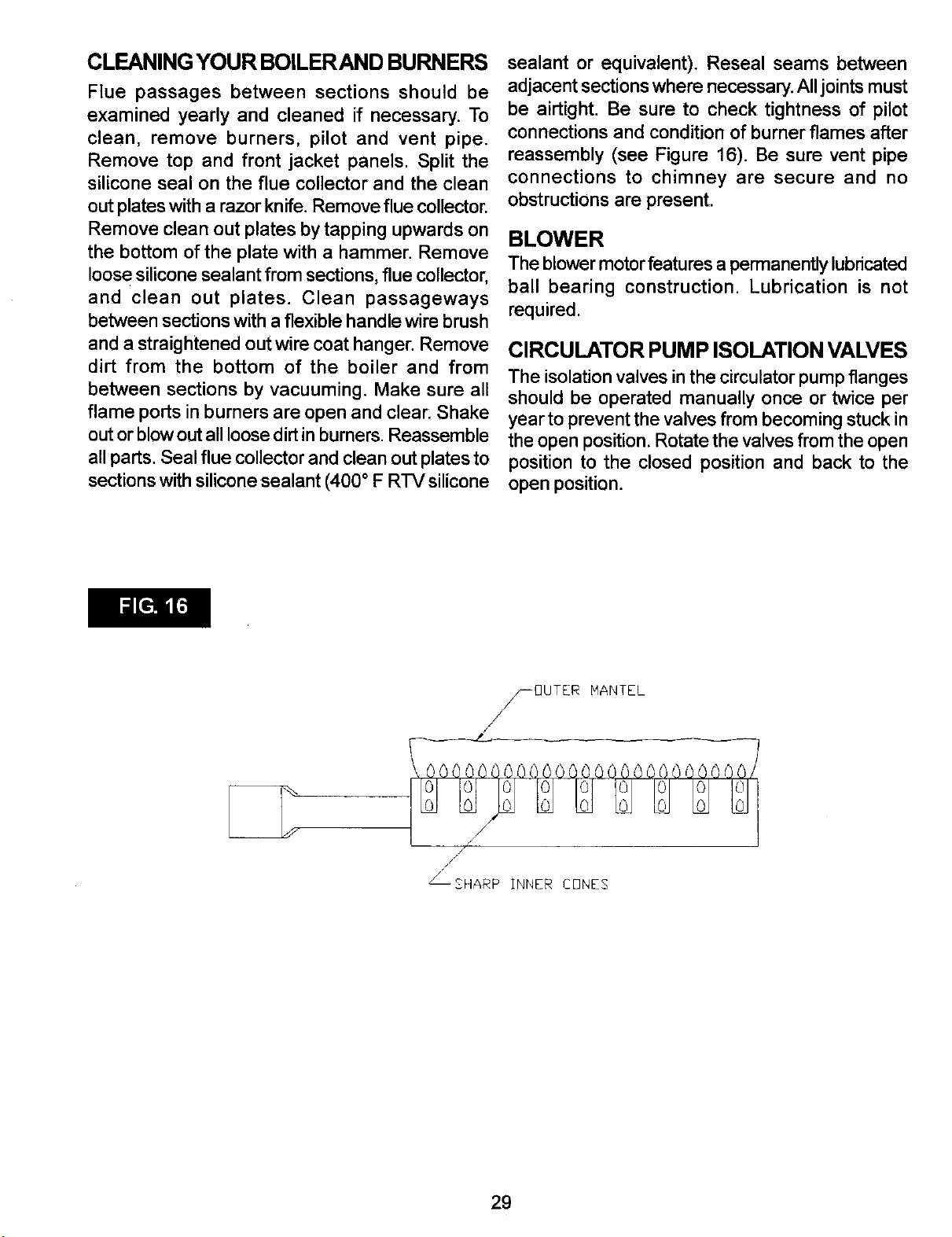
CLEANINGYOUR BOILERAND BURNERS
Flue passages between sections should be
examined yearly and cleaned if necessary. To
clean, remove burners, pilot and vent pipe.
Remove top and front jacket panels. Split the
silicone seal on the flue collector and the clean
out plates with arazor knife. Remove flue collector.
Remove clean out plates by tapping upwards on
the bottom of the plate with a hammer. Remove
loose silicone sealant from sections, flue collector,
and clean out plates. Clean passageways
between sections with a flexible handle wire brush
and astraightened out wire coat hanger. Remove
dirt from the bottom of the boiler and from
between sections by vacuuming. Make sure all
flame ports in burners are open and clear: Shake
out or blow out all loose dirt in burners. Reassemble
all parts. Seal flue collector and clean out plates to
sections with silicone sealant (400 ° F RTV silicone
sealant or equivalent). Reseal seams between
adjacent sections where necessary. All joints must
be airtight. Be sure to check tightness of pilot
connections and condition of burner flames after
reassembly (see Figure 16). Be sure vent pipe
connections to chimney are secure and no
obstructions are present.
BLOWER
The blower motor features a permanently lubricated
ball bearing construction. Lubrication is not
required.
CIRCULATOR PUMP ISOLATIONVALVES
The isolation valves in the circulator pump flanges
should be operated manually once or twice per
year to prevent the valves from becoming stuck in
the open position. Rotate the valves from the open
position to the closed position and back to the
open position.
f-OUTER lqANTEL
/
z /
J
_SHARP INNER C[3NE$
29
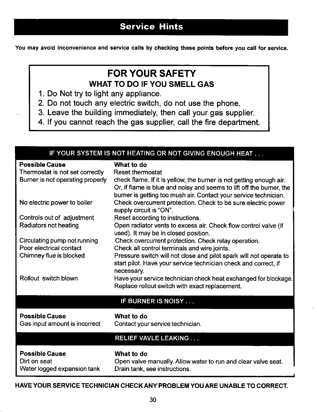
You may avoid inconvenience and service calls by checking these points before you call for service.
FOR YOUR SAFETY
WHAT TO DO IF YOU SMELL GAS
1. Do Not try to lightany appliance.
2. Do not touch any electric switch,do not use the phone.
3. Leave the buildingimmediately,then call your gas supplier.
4. If you cannot reach the gas supplier,call the fire department.
Possible Cause
Thermostat is not set correctly
Burner is not operating properly
No electric power to boiler
Controls out of adjustment
Radiators not heating
Circulating pump not running
Poor electrical contact
Chimney flue is blocked
Rollout switch blown
What to do
Reset thermostat
check flame. If it is yellow, .the burner is not getting enough air.
Or, ifflame is blue and noisy and seems to lift off the burner, the
burner is getting too mush air. Contact your service technician.
Check overcurrent protection. Check to be sure electric power
supply circuit is "ON".
Reset according to instructions.
Open radiator vents to excess air. Check flow control valve (if
used). It may be in closed position.
Check overcurrent protection. Check relay operation.
Check all control terminals and wire joints.
Pressure switch will not close and pilot spark will not operate to
start pilot. Have your service technician check and correct, if
necessary.
Have your service technician check heat exchanged for blockage.
Replace rollout switch with exact replacement.
Possible Cause
Gas input amount is incorrect What to do
Contact your service technician.
Possible Cause
HAVE YOUR SERVICE TECHNICIAN CHECKANY PROBLEM YOU ARE UNABLE TO CORRECT.
30
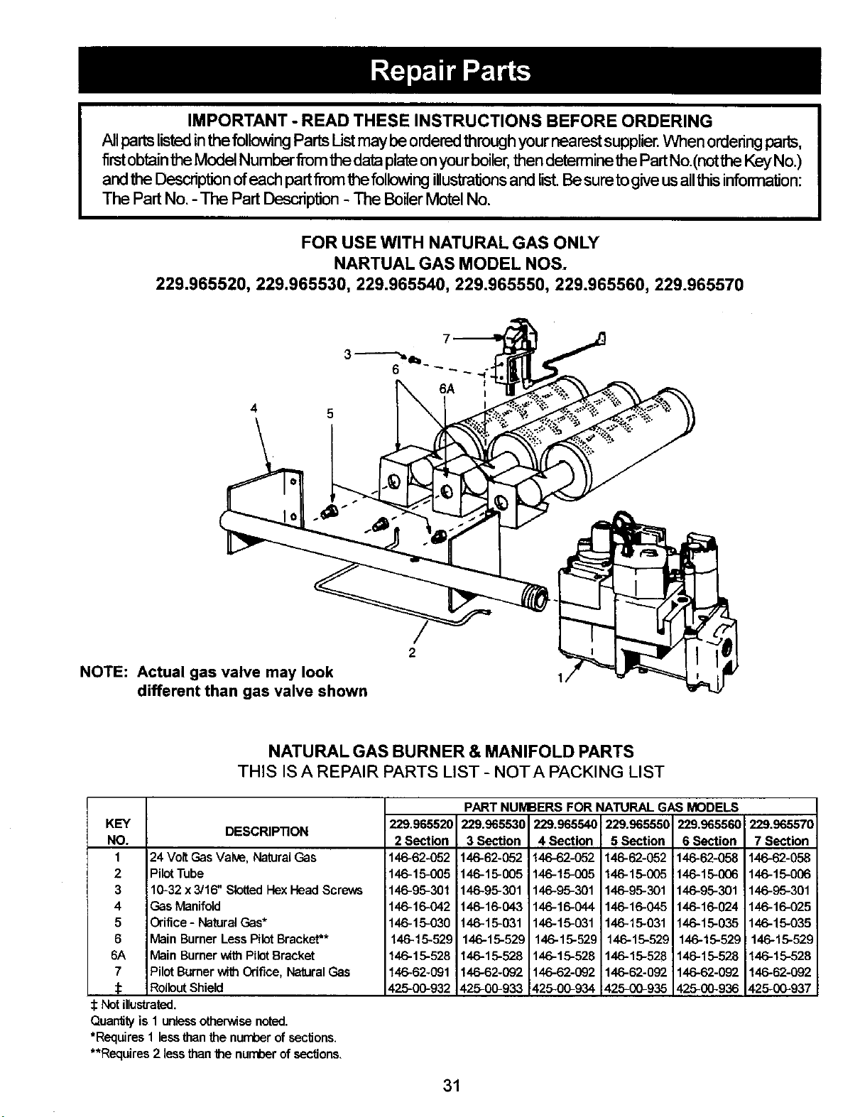
IMPORTANT - READ THESE INSTRUCTIONS BEFORE ORDERING
All parts listed in the following Parts Listmay be ordered through your nearest supplier. When ordering parts,
firstobtain the Model Numberfrom the data plate onyour boiler, then determine the Part No.(not the Key No.)
and the Description ofeach part from the following illustrations and list. Besure to give us allthis information:
The Part No. -The Part Descrip'don - The Boiler Motel No.
FOR USE WITH NATURAL GAS ONLY
NARTUAL GAS MODEL NOS.
229.965520, 229.965530, 229.965540, 229.965550, 229.965560, 229.965570
5
NOTE: Actual gas valve may look
different than gas valve shown
2
NATURAL GAS BURNER & MANIFOLD PARTS
THIS IS A REPAIR PARTS LIST - NOTA PACKING LIST
DESCRIPTION
KEY
NO.
124 Vott Gas Valve, Natural Gas
2 Pilot Tube
310-32 x 3/16" SlottedHex Head Screws
4 Gas Manifold
5Orifice - Natural Gas*
6 Main Burner Less Pilot Bracket**
6A Main Burner with Pilot Bracket
7 Pilot Burner with Orifice, NeUral Gas
_: Rollout Shield
229.965520
2 Section
146-62-052
146-15-005
146-95-301
146-16-042
146-15-030
146-15-529
146-15-528
146-62-091
425-00-932
PART NUMBERS FOR NATURAL GAS MODELS
229.965530
3 Section
146-62-052
146-15-005
146-95-301
146-16-043
146-15-031
146-15-529
146-15-528
146-62-092
425-00-933
229.965540
4 Section
146-62-052
146-15-005
146-95-301
146-15-044
146-15-031
146-15-529
146-15-528
146-62-092
425-00-934
229.965550
5 Section
146-62-052
146-15-005
146-96-301
146-16-045
146-15-031
146-15-529
146-15-528
146-62-092
426-00-935
229.965560
6 Section
146-62-058
146-!5-006
146-95-301
146-16-024
146-15-035
146-15-529
146-15-528
146-62-092
425-00-936
!229.965570
7 Section
146-62-058
146-15-006
146-95-301
146-16-025
146-15-035
146-15-529
146-15-528
146-62-092
425-00-937
Notillustrated.
Quan_tyis 1 unlessotherwisenoted.
*RequiresI lessthanthenumberofsections.
**Requires2 lessthanthe numberofsections.
31
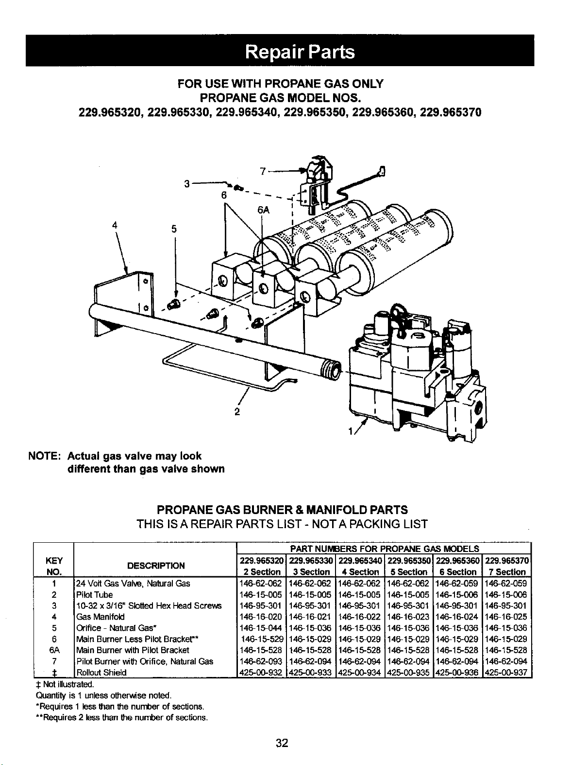
FOR USE WITH PROPANE GAS ONLY
PROPANE GAS MODEL NOS.
229.965320, 229.965330, 229.965340, 229.965350, 229.965360, 229.965370
4 5
NOTE: Actual gas valve may look
different than gas valve shown
2
PROPANE GAS BURNER & MANIFOLD PARTS
THIS IS AREPAIR PARTS LIST- NOT APACKING LIST
KEY DESCRIPTION
NO.
1 24 Volt Gas Valve, NaturalGas
2 PilotTube
310-32 x 3/16" Slotted Hex HeadScrews
4Gas Manifold
5Orifice - Natural Gas*
6 Main Burner Less Pilot Bracket**
6A Main Burner with PilotBracket
7PilotBurner with Orifice, Natural Gas
_olleut Shield
:Not illustrated.
Quantityis 1 unlessotherwise noted.
*Requires 1 lessthan the number of sec_ons.
**Requires 2 less than the nun'_er of sections.
229.965320
2 Section
146-62-062
146-16-005
146-95-301
146-16-020
14e-15-044
146-15-529
146-16-528
146-62-093
426-00-932
PART NUMBERS FOR PROPANE GAS MODELS
229,965330 229.965340 229.965350 229,965360
3 Section
146-62-062
146-15-005
146-96-301
146-16-021
146-15-036
146-15-029
146-16-528
146-62-094
426-00-933
4 Section
146-62-062
146-16-005
146-95-301
146-16-022
146-16-036
146-15-029
146-16-528
146-62-094
426-00-934
5 Section
146-62-062
146-16-005
146-95-301
146-16-023
146-16-036
146-15-029
146-15-528
146-62-094
425-00-935
6 Section
146-62-059
146-16-006
146-96-301
146-16-024
146-16-036
146-16-029
145-15-528
145-62-094
_-25-00-936
229.965370
7 Section
146-62-059
146-t6-006
146-96-301
146-16-025
146-15-036
146-16-029
146-16-528
146-62-094
425-00-937
32

SEARS INDUCEDDRAFTBOILERS
229.965520, 229.965530, 229.965540, 229.965550, 229.965560, 229.965570
229.965320, 229.965330, 229.965340, 229.965350, 229,965360, 229.965370
15
/
12 \
\
14
DESCRIPTION
KEY
1 Jacket, Right Side Panel
2 Blower Cover Plate
3 Rating Plate
4 Jacket Tie Bar
5 Boiler Base
6Insulation, Base Side (2 Required)
6Insulation, Base Front
6 Insulation, Base Rear
7Nipple, Boiler
8 Jacket, Left Side Panel
9 Jacket, Front Panel
10 1/4" Tie Rod, (2 Reqired)
11 Nut & Washer
12 Section, Left End
13 Section, Intermediate
14 Jacket, Top Panel
15 Cleanout Plate(s)
16 Flue Collector
17 Section, Right End
18 Jacket, Back Panel
:1: Jacket, Complete
19 #1g x 1/2 Sheet Metal Screw
:[: Block Assembly (7,10,11,12,13,17))
Combustable Floor Plate
:1:Not illustrated
2 SECTION
730-00-1050
730-00-1170
146-86-005
425-01-494
425-01-733
146-14-020
146-14-112
146-14-122
433-01-976
736-00-1040
730-06-1032
146-05-008
146-95-041
410-01-019
730-06-1012
425-01-539
730-00-3002
410-01-017
730-06-1022
730-00-1002
146-95-074
416-0%212
146-14-031
3 SECTION
730-00-1050
730-00-1170
146-80-005
425-01-495
425-01-734
146-14-020
146-14-113
146-14-123
433-01-976
730-00-1040
730-00-1033
146-05-002
146-95-041
410-01-019
416-01-018
730-00-1013
425-01-540
730-00-3003
410-01-017
730-00-1023
730-00-1003
146-95-074
416-0%312
146.-14-031
PART NUMBERS FOR
4 SECTION 5 SECTION
736-06-1050 730-00-1050
730-00-1170 730-00-1170
146-80-005 146-80-005
425-01-496 425-01-497
425-01-735 425-01-736
146-14-020 146-14-020
146-14-114 146-14-115
146-14-124 146-14-125
433-01-976 433-01-976
730-00-1040 736-00-1040
730-00-1034 730-06-1035
146-05-002 146-05-051
146-95-041 146-95-041
410-01-019 410-01-019
410-01-018 410-01-018
730-00-1014 730-06-1015
425-01-541 425-01-542
730-00-3004 736-06-3005
410-01-017 416-01-017
730-00-1024 730-00-1025
730-00-1004 736-00-1005
146-95-074 146-95-074
410-01-42 410-0%512
146-14-031 146-14-031
6 SECTION
730-00-1050
730-00-1170
146-80005
425-01-498
425-01-737
146-14-020
146-14-116
146-14-126
433-01-976
730-00-1040
736-00-1036
146-05-053
146-96-041
410-01-019
410-01-018
730-00-1016
425-01-540
425-01-541
730-06-3006
410-01-017
730-00-1026
730-00-1006
146-95-074
410-01-612
146-14-032
7 SECTION
730-00-1050
730-06-1170
146-86-005
425-01-499
425-01-738
146-14-020
146-14-117
146-14-127
433-01-976
730-00-1040
730-06-1037
146-05-005
146-95-041
410-01-019
416-01-018
736-00-1017
425-01-541
736-00-3007
410-01-017
730-00-1027
730-06-1007
146-95-074
410-01-712
146-14-032
33
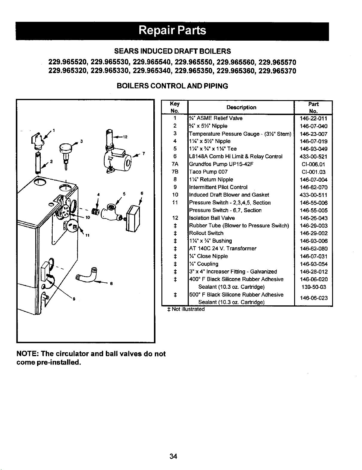
SEARSINDUCED DRAFT BOILERS
229.965520, 229.965530, 229.965540, 229.965550, 229.965560, 229.966570
229.965320, 229.965330, 229.965340, 229.965350, 229.965360, 229.965370
BOILERS CONTROL AND PIPING
5 S
Key
No.
1
2
3
4
5
6
7A
7B
8
9
10
11
12
$
$
$
$
t
Description
/4"ASME Relief Valve
/4"x 5½" Nipple
Temperature Pessure Gauge - (3½" Stem)
1¼" x 5½" Nipple
1¼" x ¾" x 1¼" Tee
L8148A Comb Hi Limit & Relay Control
Grundfos Pump UP15-42F
Taco Pump 007
1¼" Return Nipple
Intermittent Pilot Control
Induced Draft Blower and Gasket
Pressure Switch - 2,3,4,5, Section
Pressure Switch -6,7, Section
Isolation Ball Valve
Rubber Tube (Blower to Pressure Switch)
Part
No.
146-22-011
146-07-040
146-23-007
146-07-019
146-93-049
433-00-521
CI-006,01
Cl-001.03
146-07-004
146-62-070
433-00-511
146-55-006
146-55-005
146-26-043
146-29-003
Rollout Switch
1¼" x_" Bushing
AT 140C 24 V. Transformer
/_"Close Nipple
¼" Coupling
3" x 4" Increaser Fitting -Galvanized
400° F Black Silicone Rubber Adhesive
Sealant (10,3 oz. Cartridge)
500° F Black Silicone Rubber Adhesive
Sealant (10.3 oz. Cartridge)
146-29-002
146-93-006
146-62-O80
146-07-031
146-93-054
146-28-012
146-06-020
139-50-03
146-06-023
:1:Not illustrated
NOTE: The circulator and ball valves do not
come pre-installed.
34

35
Electronic Ignition
Gas-Fired
Hot Water
Induced Draft
Boiler
Now thatyou have purchased your Boiler, should a need
ever exist for repair parts or service, simply contact any
Sears service Center. Be sure to provide all pertinent
facts when you call or visit.
The model number of your Boiler will be found on the
model plate on the side of the Boiler.
WHEN ORDERING REPAIR PARTS, ALWAYS GIVE
THE FOLLOWING INFORMATION:
• PART NUMBER
• MODEL NUMBER • PART DESCRIPTION
• NAME OF ITEM
All parts listed may be order from any Sears Service
Center.
Ifthe parts you need are not stocked locally, your order
will be electronically transmitted to a Sears Repair Parts
Distribution Center for handling.
When Sears arranges the installation, you can be sure
the job is done right. We will arrange for professional
workmanship..., and we'll take care of the entire project.
What's more, during installation you get insured
protection .... against property damage and also against
accidents to workmen. All you have to do is talk to your
nearest Sears store today for detailed information.
14683601 Rev 1, August 2003