
OWNER MANUAL
ACTIVE TWO-WAY
LINE ARRAY MODULE
HDL 50-A 4K


1. INTRODUCTION
The demands of modern sound reinforcement systems are higher than ever before. Besides pure performance - high sound
pressure levels, constant directivity and sound quality other aspects are important for rental and production companies such
as reduced weight and ease of use to optimize transport and rigging time.
HDL 50-A 4K is changing the concept of large format arrays, providing primary performances to an extended market of
professional users.

2. GENERAL SAFETY INSTRUCTION AND WARNINGS
IMPORTANT NOTE
Before connecting using or rigging the system, please read this instruction manual carefully and keep it on hand for
future reference. The manual is to be considered an integral part of the product and must accompany the system when
it changes ownership as a reference for correct installation and use as well as for the safety precautions. RCF S.p.A. will
not assume any responsibility for the incorrect installation and/or use of the product.
WARNING
• To prevent the risk of fire or electric shock, never expose this equipment to rain or humidity.
• The system HDL line arrays should be rigged and flown by professional riggers or trained personnel under
professional riggers’ supervision.
• Before rigging the system carefully read this manual.
SAFETY PRECAUTIONS
1. All the precautions, in particular the safety ones, must be read with special attention, as they provide important
information.
2. Power supply from mains. The mains voltage is sufficiently high to involve a risk of electrocution; install and connect
this product before plugging it in. Before powering up, make sure that all the connections have been made correctly
and the voltage of your mains corresponds to the voltage shown on the rating plate on the unit, if not, please
contact your RCF dealer. The metallic parts of the unit are earthed through the power cable. An apparatus with
CLASS I construction shall be connected to a mains socket outlet with a protective earthing connection. Protect the
power cable from damage; make sure it is positioned in a way that it cannot be stepped on or crushed by objects. To
prevent the risk of electric shock, never open this product: there are no parts inside that the user needs to access.
3. Make sure that no objects or liquids can get into this product, as this may cause a short circuit. This apparatus
shall not be exposed to dripping or splashing. No objects filled with liquid, such as vases, shall be placed on this
apparatus. No naked sources (such as lighted candles) should be placed on this apparatus.
4. Never attempt to carry out any operations, modifications or repairs that are not expressly described in this manual.
Contact your authorized service centre or qualified personnel should any of the following occur:
- the product does not function (or functions in an anomalous way).
- the power cable has been damaged.
- objects or liquids have got in the unit.
- the product has been subject to a heavy impact.
5. If this product is not used for a long period, disconnect the power cable.
6. If this product begins emitting any strange odours or smoke, switch it off immediately and disconnect the power
cable.
7. Do not connect this product to any equipment or accessories not foreseen.
For suspended installation, only use the dedicated anchoring points and do not try to hang this product by using
elements that are unsuitable or not specific for this purpose. Also check the suitability of the support surface to
which the product is anchored (wall, ceiling, structure, etc.), and the components used for attachment (screw
anchors, screws, brackets not supplied by RCF etc.), which must guarantee the security of the system / installation
over time, also considering, for example, the mechanical vibrations normally generated by transducers.
To prevent the risk of falling equipment, do not stack multiple units of this product unless this possibility is specified
in the user manual.
8. RCF S.p.A. strongly recommends this product is only installed by professional qualified installers (or specialised
firms) who can ensure correct installation and certify it according to the regulations in force.

The entire audio system must comply with the current standards and regulations regarding electrical systems.
9. Supports and trolleys.
The equipment should be only used on trolleys or supports, where necessary, that are recommended by the
manufacturer. The equipment / support / trolley assembly must be moved with extreme caution. Sudden stops,
excessive pushing force and uneven floors may cause the assembly to overturn.
10. There are numerous mechanical and electrical factors to be considered when installing a professional audio system
(in addition to those which are strictly acoustic, such as sound pressure, angles of coverage, frequency response,
etc.).
11. Hearing loss.
Exposure to high sound levels can cause permanent hearing loss. The acoustic pressure level that leads to hearing
loss is different from person to person and depends on the duration of exposure. To prevent potentially dangerous
exposure to high levels of acoustic pressure, anyone who is exposed to these levels should use adequate protection
devices. When a transducer capable of producing high sound levels is being used, it is therefore necessary to wear
ear plugs or protective earphones. See the manual technical specifications to know the maximum sound pressure
level.
To prevent the occurrence of noise on line signal cables, use screened cables only and avoid putting them close to:
- Equipment that produces high-intensity electromagnetic fields.
- Power cables
- Loudspeaker lines.
OPERATING PRECAUTIONS
- Place this product far from any heat sources and always ensure an adequate air circulation around it.
- Do not overload this product for a long time.
- Never force the control elements (keys, knobs, etc.).
- Do not use solvents, alcohol, benzene or other volatile substances for cleaning the external parts of this product.
GENERAL OPERATING PRECAUTIONS
• Do not obstruct the ventilation grilles of the unit. Situate this product far from any heat sources and always ensure
adequate air circulation around the ventilation grilles.
• Do not overload this product for extended periods of time.
• Never force the control elements (keys, knobs, etc. ).
• Do not use solvents, alcohol, benzene or other volatile substances for cleaning the external parts of this product.
CAUTION
To prevent electric shock hazard, do not connect to mains power supply while grille is removed

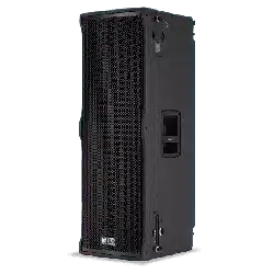
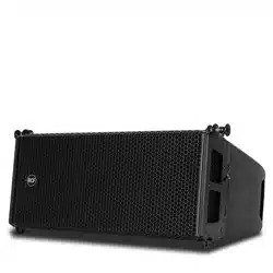
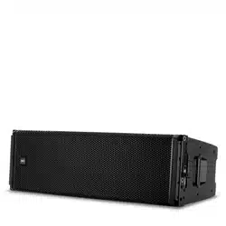
3. THE HDL 50-A 4K SYSTEM
The HDL 50-A 4K is a true active high power ready to use touring system for large events, indoors and outdoors.
Equipped with 2x12” woofers, four symmetrical 6.5” midranges and two 2” drivers, it offers excellent playback quality
and high sound pressure levels with a built in 4000W RMS powerful digital amplifier that delivers superior SPL, while
reducing energy requirement.
Each component, from the power supply to the input board with DSP, to the output stages to woofers and drivers, has
been consistently and specially developed by RCF’s experienced engineering teams for the realization of the HDL 50-A
4K system, with all components carefully matched to each other.
This complete integration of all components allows not only superior performance and maximum operational reliability,
but also provides users easy handling and plug & play comfort.
Besides this important fact, active speakers offer valuable advantages: while passive speakers often need long cable
runs, the energy loss due to the cable resistance is a huge factor. This effect is not seen in powered speakers where the
amplifier is just a couple of centimeters away from the transducer.
Using advanced neodymium magnets and a groundbreaking new housing constructed from lightweight plywood and
polypropylene, it has a remarkably low weight for easy handling and flying.

4. POWER REQUIREMENTS AND SET-UP
WARNING
• The system is designed to operate in hostile and demanding situations. Nevertheless it is important to take
extremely care of the AC power supply and set up a proper power distribution.
• The system is designed to be GROUNDED. Always use a grounded connection.
• PowerCon appliance coupler is a AC mains power disconnection device and must be readily accessible during and
after the installation.
VOLTAGE
The HDL 50-A 4K A amplifier is designed to work within the following AC Voltage limits: minimum voltage 100 Volt,
maximum voltage 260 Volt. If the voltage goes below the minimum admitted voltage the system stops working. If the
voltage goes higher than the maximum admitted voltage the system can be seriously damaged. To obtain the best
performances from the system it is very important that the voltage drop it is as low as possible.
CURRENT
The following are the long term and peak current requirement for each HDL 50-A 4K A module:
The total current requirement is obtained multiplying the single current requirement by the number of modules. To obtain the best
performances make sure that the total burst current requirement of the system doesn’t create a significant voltage drop on the
cables.
GROUNDING
Make sure that all the system is properly grounded. All the grounding points shall be connected to the same ground
node. This will improve reducing hums in the audio system.
HDL 50-A 4K, AC CABLES DAISY CHAINS
Each HDL 50-A 4K A module is provided with a Powercon outlet
to daisy chain other modules. The maximum number of modules
that is possible to daisy chain is:
230 VOLT: 2 modules total
115 VOLT: 1 module total
WARNING - RISK OF FIRE
A superior number of modules in daisy chain will exceed
the Powercon connector maximum ratings and create a
potentially dangerous situation.
POWERING FROM THREE PHASE
When the system is powered from a three phase power distribution it is very important to keep a good balance in the
load of each phase of the AC power. It is very important to include subwoofers and satellites in power distribution
calculation: both subwoofers and satellites shall be distributed between the three phases.
VOLTAGE LONG TERM
230 Volt 6.3 A
115 Volt 2 x 6.3 A
POWERCON IN
POWERCON OUT

5. RIGGING THE SYSTEM
RCF has developed a complete procedure to set up and hang an HDL 50-A 4K line array system starting from software
data, enclosures, rigging, accessories, cables, until the final installation.
GENERAL RIGGING WARNINGS AND SAFETY PRECAUTIONS
• Suspending loads should be done with extreme caution.
• When deploying a system always wear protective helmets and footwear.
• Never allow people to pass under the system during the installation process.
• Never leave the system unattended during the installation process.
• Never install the system over areas of public access.
• Never attach other loads to the array system.
• Never climb the system during or after the installation
• Never expose the system to extra loads created from the wind or snow.
WARNING
• The system must be rigged in accordance with the laws and regulations of the Country where the system is used. It
is responsibility of the owner or rigger to make sure that the system is properly rigged in accordance with Country
and local laws and regulations.
• Always check that all the parts of the rigging system that are not provided from RCF are:
- appropriate for the application
- approved, certified and marked
- properly rated
- in perfect condition
• Each cabinet support the full load of the part of the system below. It is very important that each single cabinet of
the system is properly checked

“RCF SHAPE DESIGNER” SOFTWARE AND SAFETY FACTOR
The suspension system is designed to have a proper safety factor (configuration dependent). Using the “RCF Easy
Shape Designer” software it is very easy to understand safety factors and limits for each specific configuration. To
better comprehend in which safety range the mechanics are working a simple introduction is needed: HDL 50-A 4K
arrays’ mechanics are built with certified UNI EN 10025 Steel. RCF prediction software calculates forces on every single
stressed part of the assembly and shows the minimum safety factor for every link. Structural steel has a stress-strain (or
equivalent Force-Deformation) curve as in the following:
The curve is characterized by two critical points: the Break Point
and the Yield Point. The tensile ultimate stress is simply the
maximum stress attained. Ultimate tensile stress is commonly
used as a criterion of the strength of the material for structural
design, but it should be recognized that other strength properties
may often be more important. One of these is certainly the Yield
Strength. Stress-strain diagram of structural steel exhibit a sharp
break at a stress below the ultimate strength. At this critical stress,
the material elongates considerably with no apparent change in
stress. The stress at which this occurs is referred to as the Yield
Point. Permanent deformation may be detrimental, and the industry
adopted 0.2% plastic strain as an arbitrary limit that is considered
acceptable by all regulatory agencies. For tension and compression,
the corresponding stress at this offset strain is defined as the yield.
In our prediction software the Safety Factors are calculated considering the Maximum Stress Limit equal to the
Yield Strength, according with many international standards and rules.
The resulting Safety Factor is the minimum of all the calculated safety factors, for each link or pin.
This is where you are working with a SF=7
Depending on local safety regulations and on the situation, the
required safety factor can vary. It is responsibility of the owner or
rigger to make sure that the system is properly rigged in accordance
with Country and local laws and regulations.
The “RCF Shape Designer” software gives detailed information of
the safety factor for each specific configuration.
The results are classified in four classes:
GREEN SAFETY FACTOR > 7 SUGGESTED
YELLOW 4 > SAFETY FACTOR > 7
ORANGE 1.5 > SAFETY FACTOR > 4
RED SAFETY FACTOR > 1.5 NEVER ADMITTED

WARNING
• The safety factor is the result of the forces acting on fly bar’s and system’s front and rear links and pins and depends
on many variables:
- number of cabinets
- fly bar angles
- angles from cabinets to cabinets. If one of the cited variables change the safety factor MUST BE recalculated
using the software before rigging the system.
• In case the fly bar is picked up from 2 motors make sure that the fly bar angle is correct. An angle different from the
angle used in the prediction software can be potentially dangerous. Never allow persons to stay or pass under the
system during the installation process.
• When the fly bar is particularly tilted or the array is very curved the centre of gravity can move out from the rear
links. In this case the front links are in compression and the rear links are supporting the total weight of the system
plus the front compression. Always check very carefully with the “RCF Easy Shape Designer” software all this kind of
situations (even with a small number of cabinets).
PREDICTION SOFTWARE – SHAPE DESIGNER
RCF Easy Shape Designer is a temporary software, useful for the setup of the array, for mechanics and for proper preset
suggestions.
The optimal setting of a loudspeaker array cannot ignore the basics of acoustics and the awareness that many factors
contribute to a sonic result that matches expectations. RCF provides the user with simple instruments that help the
setting of the system in an easy and reliable way.
This software will soon be replaced by a more complete software for multiple arrays and complex venue simulation with
maps and graphs of the results.
RCF recommends this software to be used for each type of HDL 50-A 4K configuration.
System particularly tilted System very curved
SOFTWARE INSTALLATION
The software was developed with Matlab 2015b and requires Matlab programming libraries. At the very first installation
user should refer to the installation package, available from the RCF website, containing the Matlab Runtime (ver. 9) or
the installation package that will download the Runtime from the web. Once the libraries are correctly installed, for all
the following version of the software the user can directly download the application without the Runtime. Two versions,
32-bit and 64-bit, are available for the download.
IMPORTANT: Matlab no longer supports Windows XP and hence RCF Easy Shape Designer (32 bit) doesn’t work with
this OS version.
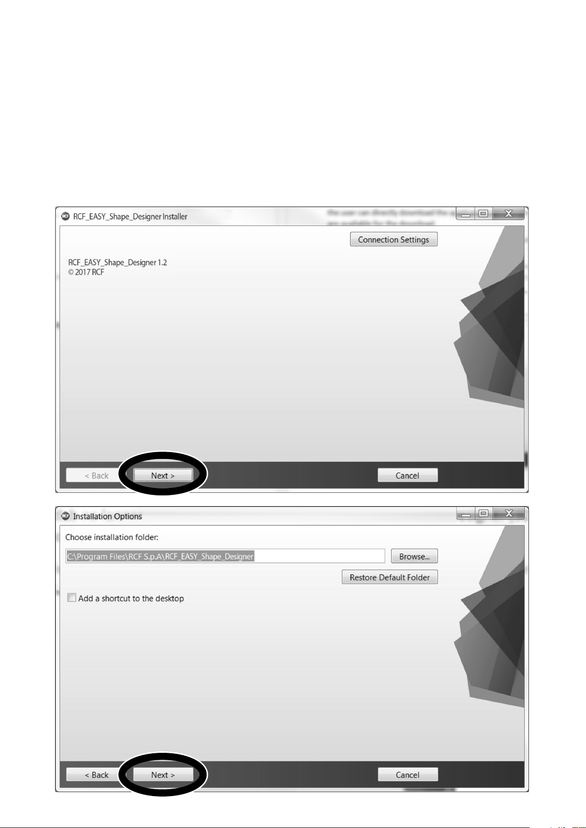
You may wait a few seconds after the double click on the installer because the software checks if Matlab Libraries are
available. After this step the installation begins. Double-click the last installer (check for the last release in the download
section of our website) and follow the next steps.


After the choice of folders for RCF Easy Shape Designer software (Figure 2) and Matlab Libraries Runtime the installer
takes a couple of minutes for the installation procedure.

DESIGNING THE SYSTEM
The RCF Easy Shape Designer software is divided into two macro sections: the left part of the interface is dedicated
to project variables and data (size of audiences to cover, height, number of modules, etc.), the right part shows the
processing results.
At first the user should introduce the audience data choosing the proper pop-up menu depending on the size of the
audience and introducing the geometrical data. It is also possible to define the height of the listener.
The second step is the array definition selecting the number of cabinets in the array, the hanging height, the number of
hanging points and the kind of available flybars. When selecting two hanging points consider those points positioned at
the flybar extremes.
The height of the array should be considered referred to the bottom side of the flybar, as shown in the picture below.
After entering all the data input in the left part of the user interface, by pressing the AUTOSPLAY button the software will
perform:
- Hanging point for the shackle with A or B position indicated if a single pickup point is selected, rear and front load if
two pickup points are selected.
- Flybar tilt angle and cabinet splays (angles that we have to set to each cabinet before lifting operations).
- Inclination that each cabinet will take (in case of one pick up point) or will have to take if we were to tilt the cluster
with the use of two engines. (two pick up points).
- Total load and Safety Factor calculation: if the selected setup doesn’t give Safety Factor > 1.5 the text message
shows in red color the failure to meet the minimum conditions of mechanical safety.
- Low Frequency Presets (a single preset for all the array) for RDNet use or for rear panel rotary knob use (“Local”).
- High Frequency Presets (a preset for every array module) for RDNet use or for rear panel rotary knob use (“Local”).
HEIGHT

Every time the user changes flybar tilt, splay angles, humidity, temperature or height of the array, the software
automatically recalculates the presets. It is possible to save and load a project of the Shape Designer using the “Setup”
menu.
The autosplay algorithm was developed for optimum coverage of the audience size. The use of this function is
recommended for the optimization of the array aiming. A recursive algorithm chooses for every cabinet the best angle
available in the mechanics.
It is also possible to export as a text file the presets configuration for air and humidity absorption to RDNet using the
“Presets” menu.
Refer to next chapter or to the RD-Net manual for more information about this functionality.
RECOMMENDED WORKFLOW - EASE FOCUS 3
Pending the official and definitive simulation software, RCF recommends the use of RCF Easy Shape Designer together
with Ease Focus 3. Because of the need of interaction between different software, the recommended workflow assumes
the following steps for every array in the final project:
1. RCF Easy Shape Designer: audience and array setup. Calculation in “autosplay” mode of flybar tilt, cabinet, splays,
Low Frequency preset and High Frequency presets.
2. Focus 3: reports here the angles, tilt of flybar and presets generated by Shape Designer.
3. RCF Easy Shape Designer: manual modify of splay angles if the simulation in Focus 3 does not give satisfactory
results.
4. Focus 3: reports here the new angles, tilt of flybar and presets generated by Shape Designer.
Repeat the procedure until good results are achieved.
NOTE: the 3D model inside the GLL file permits inside AFMG Focus the selection of the “Local” presets. This implies
the use of 4 of the 15 presets for the simulation. This limitation will be overcome with the release of the official RCF
simulation software.
LOW AND HIGH FREQUENCY MANAGEMENT
LOW FREQUENCY PRESETS
In the low frequency range the interaction between the sound of single cabinets produces an increase of sound level in
low frequencies proportional to the number of loudspeakers that make up the cluster. This effect unbalances the global
equalization of the system: the interaction between the loudspeakers decreases, increasing the frequency (they become
more directive).
For the control of the displacement described above it is necessary to reduce in the global equalization the level of the
low frequencies progressively reducing the gain if the frequency decreases (low shelf filter). The RCF Easy Shape Designer
software helps the user to give a recommended cluster preset.
The preset is suggested by the software considering the number of the cabinets in the cluster: the final tuning of the
system should be done with measurements and listening sessions, considering the environmental conditions.
LOW FREQUENCY PRESET USING RD-NET
In RDNet software nine presets are available: from Shape Designer it is possible to export the recommended cluster
preset and it could be imported directly on RDNet. The export/import procedure is the same for the High or Low
Frequencies and it will be explained in the following paragraphs.
The tuning of the system (presets change) should be done in RDNet selecting all the cabinets in the cluster and using
proper buttons (up and down arrows) to increase or decrease the number of the preset.

LOW FREQUENCY PRESET USING REAR PANEL ROTARY KNOB
The available presets in the rear panel of the loudspeaker, named as “Local” in the software, are only four of the nine
available in RDNet. The numbers are proportional, in terms of gain, to the reduction applied to the low frequencies of all
the clusters.
HIGH FREQUENCY PRESET
The sound propagation, in particular the high frequencies (1.5 KHz and up), depends essentially on the conditions of the
air in which it travels. We can generally affirm that air absorbs high frequencies and the amount of absorption depends
on temperature, humidity and the distance that the sound should would carry.
The decibel decrease is well modelled by a mathematical formula that combines the three parameters (temperature,
humidity and distance) giving a profile of the absorption in function of the frequency.
In the case of a loudspeaker array the goal is the audience coverage
with the best possible uniformity, obtainable only by compensating
for the absorption introduced by air. It is easy to understand that
every cabinet should be compensated differently from the other array
cabinets because the compensation should consider the distance at
which the cabinet is aiming: the cabinet at the top of the cluster will
have a bigger compensation than the one below, which in turn will
compensate more than the one below that, etc. The compensation
should be translated in terms of decibels that should be progressively
added with the increase of high frequencies.
It is important to note that the formula gives an absorption that
exponentially increases with the increase of the frequency: in
particular conditions the compensation requests a gain too high for
the amplifier.
Consider as example the following conditions: 20°C of
temperature, 30% of relative humidity and 70m of distance to
cover. In these conditions the necessary compensation, from 10
KHz and up, starts from 25 dB up to a maximum of 42 dB at 20
KHz (Figure 5). The headroom of the system cannot permit such
high gains.
Considering everything described, 15 compensation levels were
selected in order to approximate at best the infinite number of
compensation curves derived from the mathematical formula.
A low pass filter is progressively introduced with the increase of the compensation gain: the system does not need to
reproduce frequencies that could hardly reach the desired distance and that could lead to a waste of useful energy.
The picture below (Figure 6) shows the behavior of the 15 filters. These filters are designed as very small FIR (finite
impulse response) filters in order to preserve the phase coherence of the system.
The RCF Easy Shape Designer algorithm calculates the curve that best fits the one that would be seen in the real world.
Considering it is an approximation, the generated filters set should be validated with measurements or listening and
eventually changed in order to reach the desired listening experience.

RDNet Local
15 -
14 -
13 -
12 H
11 -
10 -
9 F
8 -
7 -
6 -
5 M
4 -
3 -
2 -
1 C
HIGH FREQUENCY PRESET USING RDNet
From the RCF Easy Shape Designer it is possible to export the suggested filters set to RDNet; after the selection of all the
cabinets in the cluster, by pressing the Load Presets button in the “group” property tab, the user can choose the “.txt”
file generated by RCF EASY Shape Designer.
For the proper load of the filters, the group should be composed placing as first loudspeaker of the RDNet cluster the
first one below the flybar and then all the others. Every cabinet should load a proper HF preset and the entire cluster
should load the same LF preset. Once the presets are loaded, the icon of every module in the cluster shows a green bar
with width directly proportional to the number of the preset loaded in the cabinet (the number is shown besides the
drawing).
As descripted for the Low Frequencies, the user may need to scala up or down the presets set maintaining the
compensation ratio between all the cabinets. This scaling operation can be performed with the arrow button in the
group tab. Even though the presets change is possible on every single loudspeaker, a global change by using the group
properties tab is strongly recommended in order to preserve the air absorption compensation distribution all along the
audience.
HIGH FREQUENCY PRESET USING REAR PANEL ROTARY KNOB
From RDNet the user can have access to all the fifteen presets but, using the loudspeaker rear panel rotary knob, he can
use only four of those filters. In addition, these “Local” filters are suggested by RCF Easy Shape Designer software.
HF Preset
Cluster Size Preset

RIGGING COMPONENTS
Description Accessory p/n
1 FLYBAR HDL 50-A. Suspension bar to fly a maximum of 20 modules 13360334
2 Front bracket to hook the first module
3 FLY BAR PICK UP TTL 55-A. Hooking bracket and shakle for safety chain 13360127
4 Mount bracket inclinometer
5 AC 4PIN FLY BAR TTL55. Pin for hooking to the front bracket 13360132
6 QUICK LOCK PINS KIT 4R. Pin for hooking to the rear bracket 13360340
7 PINS KIT HDL 50-A 4F. Pin for hooking the bracket for stacking applications 13360335
8 Bracket for stacking applications

1 2
3
4
ACCESSORIES
Description Accessory p/n
1 HOIST SPACING CHAIN. It allows enough space for the hang of most 2 motor chain containers
and avoids any impact on the vertical balance of the array when it is suspended from a single
pick-up point.
13360129
2 AC 2X AZIMUT PLATE. It allows the horizontal aim control of the cluster. The system must be
hook with 3 motors. 1 frontal and 2 attached to the azimuth plate.
13360351
3 FLY BAR PICK UP TTL 55-A. 13360127
4 HDL 50-A 4X KART. Necessary to carry and rigging 4 HDL 50-A 13360336
500 mm
RIGGING PROCEDURE
Installation and setup should only be carried out by qualified and authorized personnel observing the valid national Rules for
the Prevention of Accidents (RPA).
It is the responsibility of the person installing the assembly to ensure that the suspension/fixing points are suitable for the
intended use.
Always carry out a visual and functional inspection of the items before use. In the event of any doubt as to the proper
functioning and safety of the items, these must be withdrawn from use immediately.
WARNING
The steel wires between the locking pins of the cabinets and rigging components are not intended to carry any load. The
cabinet’s weight must only be carried by the Front and Splay/Rear links in conjunction with the front and rear rigging strands of
the loudspeaker cabinets and the Flying frame. Ensure all Locking pins are fully inserted and securely locked before lifting any
load.
In the first instance use RCF Easy Shape Designer software to calculate the proper set up of the system and to check the safety
factor parameter.
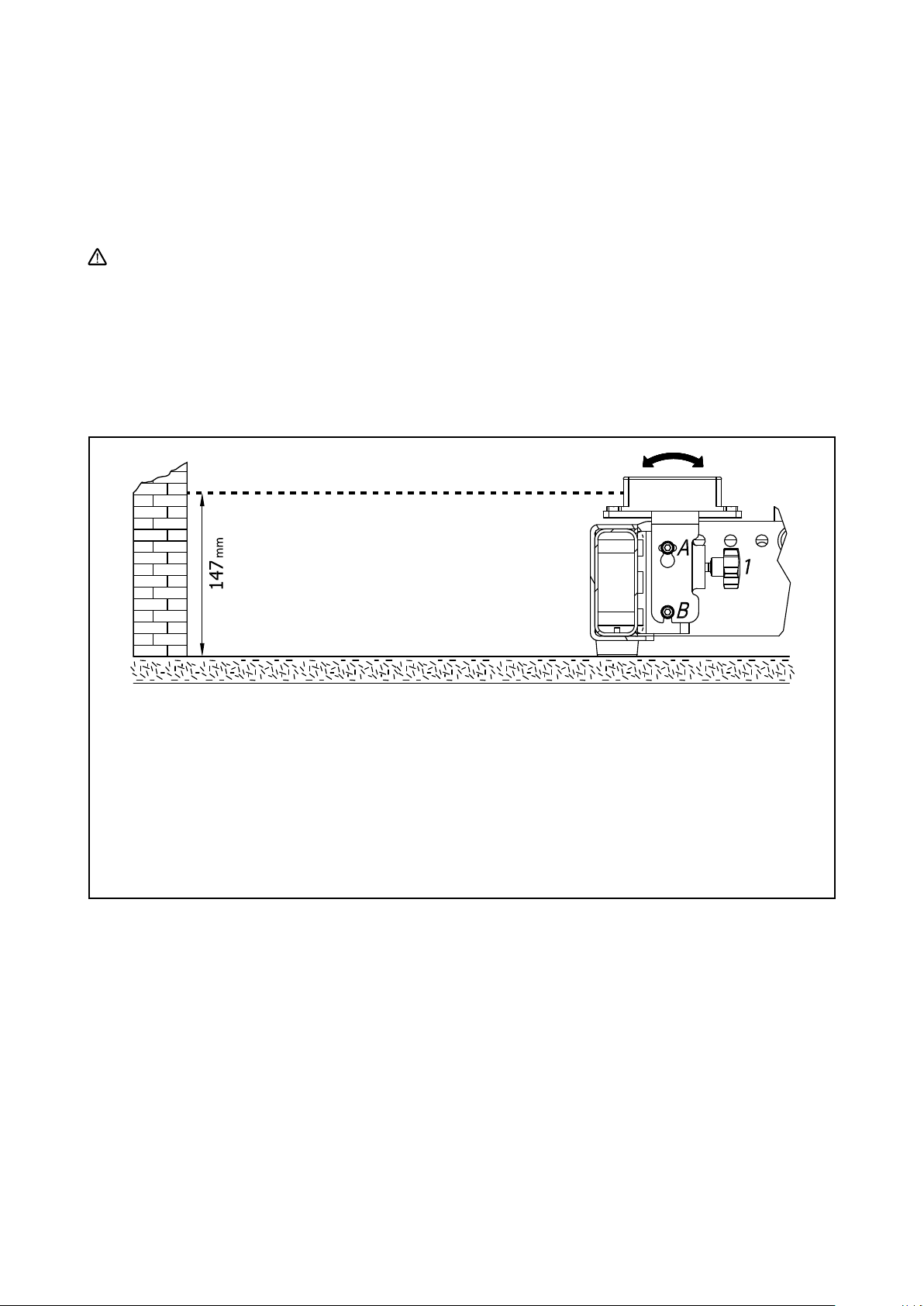
INCLINOMETER BRACKET MOUNTING
1. UNSCREW BOTH M6 SCREWS “A” AND “B”
2. SET THE PROPER INCLINATION UNSCREWING OR SCREWING THE KNOB:
POINTING THE LASER TOWARDS THE WALL,
THE DISTANCE BEETWEEN THE GROUND AND THE LASER BEAM MUST BE 147 mm
3. TIGHTEN BOTH M6 SCREWS “A” AND “B”
LASER
Note that using Rd-Net to set up the system, there will be the possibility to monitor the angles of the flybar and of each single
speaker and in case using 1 pick-up point, appropriately calculated by RCF Easy Shape Designer, the cluster will take the proper
aim and angles without the need of the inclinometer.

DUAL PICKPOINT OPERATION
With “Dual pickpoint operation” the vertical
aiming of the array is set by trimming the
hoist motors after the array has been fully
assembled and lifted to its operating position.
PREPARATION OF THE FLYBAR
Place the flybar and remove the side pins from the transport
position. The front bracket will rotate, so lock it. Fix the front
brackets in vertical position locking the pins in position 2.
Recheck the Locking pin is securely locked by briefly pulling
the Locking pin towards you.
SINGLE PICKPOINT OPERATION
(suggested for 8 modules maximum)
Fit the pickup in the proper position number, (suggested by
RCF Easy Shape Designer), and fix the pickup bracket with
the two pins. The position of the pickup defines the vertical
aiming of the entire array.
Check that all the pins are secured and locked
PICK UP POINT POSITIONING
The pickup is asymmetric and can be fit in two positions (A
and B). A position brings the shackle towards the front. B
position allows an intermediate step using the same fixing
holes.
Fix the pickup bracket with the two pins on the bracket’s
lanyard to lock the pickup.

PRESET OF SPLAY ANGLES
1. Remove all the rear locking pins of the
cabinets turning the rear bracket into the
upper module and inserting the pins in the
proper position.
2. Preset the splay angles of all cabinets, based
on RCF Easy Shape Designer software
RIGGING THE FLYBAR TO THE SPEAKERS
Move the kart with the first 4 modules under
the flybar.
Attach the flybar onto the first cabinet of the
assembly until the front links fit into the slots
at the front of the frame and fix it with the
Quick Lock pin supplied with the speaker.
Hook the flybar to the chain and lift the flybar
to a suitable height for the first cabinet.

Lift up the rear bracket of the highest cabinet.
Insert the quick lock pin in the “suspension” hole “A” of the
flybar.
Turn down the flybar until it rests on the first speaker.
Begin to lift the flybar, and when it goes on traction on the
first module, insert the locking pin in the hole “B”.
Always follow the sequence “suspension” and “locking”
and never use only the locking pin because it is not designed
to load the weight of the system. It only prevent the system
from going into compression shifting the tilt of the cluster.
Continue to lift the cluster and the angles of the speakers
will automatically switch to the correct position.
A
B
C

Stop lifting and insert and lock the second Locking pins
(Safety pins) to prevent the system from going into
compression shifting the tilt of the module, and consequently
of the cluster.
Insert the front locking pins in the proper hole. These are 2
additional pins do not load the weight of the system but
serve to maintain the fixed angle between the modules
especially if they go into compression in very curved systems
Pull out the front and rear pin from the cart and remove it
Remove all locking pins of the second cart cabinets and
preset the splay angles of all cabinets based on RCF Easy
Shape Designer software turning the rear bracket into the
upper module and inserting the pin in the proper position.
Fix the quicklock pin supplied with the speaker in the proper
hole in the front of the last speaker then lower the height of
the system in order to reduce the angle between the speakers
until they join.
SUSPENSION
ANGLE PIN 5°
LOCKING PIN
FOR SUSPENSION
PIN 5°
SECURE THE ANGLE
WITH THE RELATIVE
LOCKING PIN

Working with one pick up point this is achieved by pushing
forward the cluster and simultaneously lowers the height of
the system.
Now fix and lock the quick lock pin between the first
speaker of the cluster on the ground and the last of the
hanging cluster.
Continue to lift the cluster and the angles of the speakers
will automatically switch to the correct position.
Stop lifting and insert and lock the second Locking pins
(Safety pins) to prevent the system from going into
compression shifting the tilt of the module, and consequently
of the cluster.
Insert the front locking pins in the proper hole. These are 2
additional pins do not load the weight of the system but
serve to maintain the fixed angle between the modules
especially if they go into compression in very curved systems
Pull out the front and rear pin from the cart and remove it.
Repeat the procedure of the last 4 module for all of the
following modules.
Warning: Although with a single pick up point is possible to
compose a cluster modules 20, it is highly discuraged to use
a single pick up point with more than eight modules. The
hooking and lifting of the last modules would be dangerous
and difficult.
1. SELECT THE
INCLINATION ANGLE
Drop the cluster and remove all locking pins while it is still in traction then place the first cart under it.
Lock the front quick lock pins. Turn up the rear bracket of the module while lifting the cart. Go in the proper position with the
rear part and insert the quick lock pin in the position corresponding to a 1,4 ° hole.
Drop the cluster until the last module of four is fully leaning on each other.
Remove the rear locking pin of the first module of the next series of four and then remove the quick lock pin. Remove the front
quick lock pins, taking great care, because the upper cluster will be free to move.
Pull out the first cluster and repeat the procedure from the beginning.
DE-RIGGING PROCEDURE

A maximum of 4 x TOP cabinets are allowed to be set up as
ground stack.
The assembly of HDL 50-A in stacking uses the same flybar
as the hanging process. Proceed as follows:
Remove the pick-up front bracket and remove the laser/
inclinometer bracket.
Fix the stacking bracket in the hole number 20 of the flybar
and orientate it as shown in fig 2.
Place the first module fixing the front bracket into the fixing
point “A” of the flybar using the quick lock pins of the flybar.
Secure the front brackets by compression.
STACKING PROCEDURE
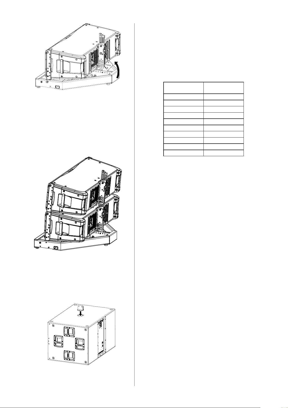
Turn the rear stacking bracket of the flybar and select the proper
angle. The correspondence of the bracket’s holes is the following:
Insert the locking pin in the proper position
Fix the next module with the front quick lock pins. Lift the rear
part of the module, insert the locking pin in the proper position
and release the module leaning with the right angle.
Repeat this operation for the following modules.
On subs 9006 and 9007 series fix the optional accessory “Ac
Connecting Plate” cod. 13360231, to M20 female screw on the
upper part of the sub.
Stacking Bracket Rear Rigging
Frame
4 4
3 3
2 2,2
1 1,4
0 0,2
-1 -1,4
-2 -2,2
-3 -3
-4 -4

Fix the flybar to the Ac Connection Plate using the two
quick lock pins.
Place the flybar to sub and insert the Ac Connecting Plate
between the two cental pipes.
6. CARE AND MAINTENANCE – DISPOSAL
TRANSPORT – STORING
During transportation ensure the rigging components are not stressed or damaged by mechanical forces. Use suitable
transport cases. We recommend the use of the RCF HDL 50-A 4K touring kart for this purpose.
Due to their surface treatment the rigging components are temporarily protected against moisture. However, ensure the
components are in a dry state while stored or during transportation and use.
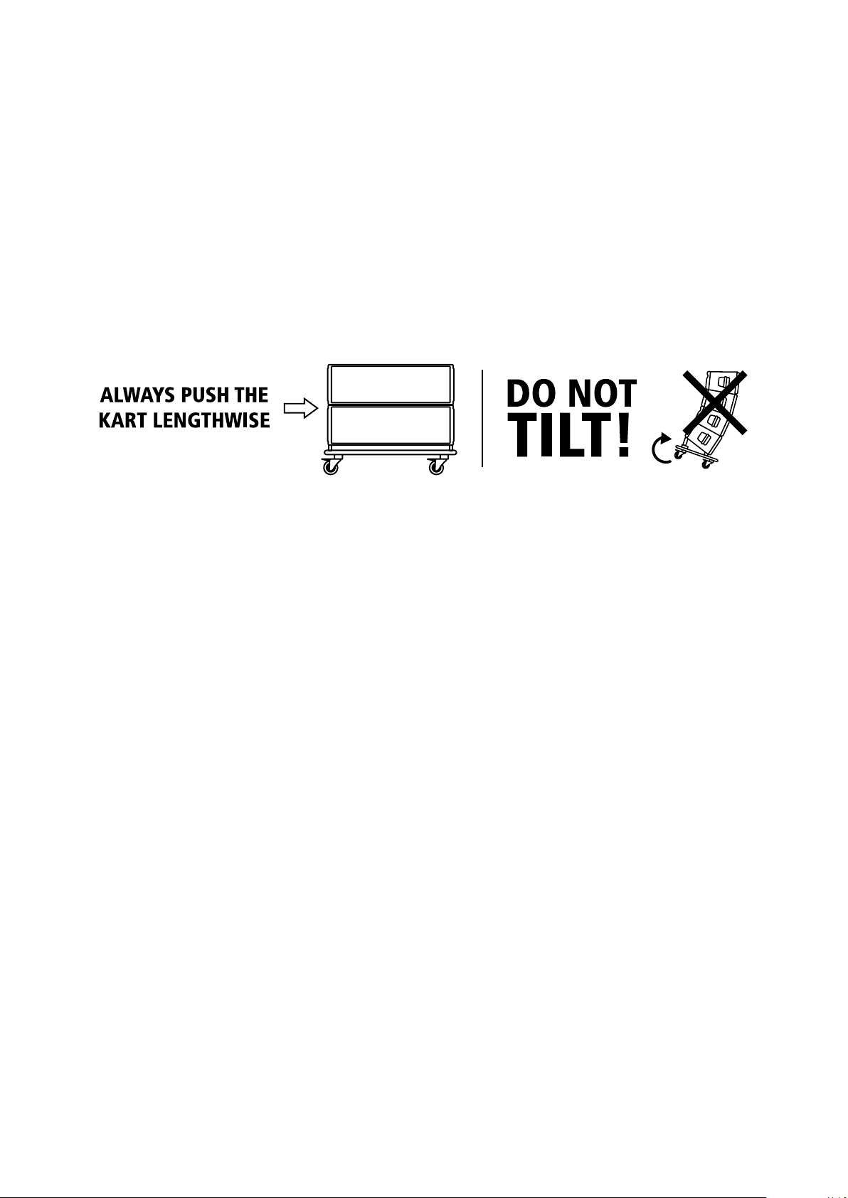
SAFETY GUIDE LINES – HDL 50-A 4K KART
Do not stack more than four HDL 50-A 4K on one Kart.
Exercise extreme caution when moving stacks of four cabinets with the kart to avoid tipping.
Do not move stacks in the front-to-back direction of the HDL 50-A 4K (long side); always move stacks sideways to avoid
tipping.

SPECIFICATIONS
HDL 50-A 4K
Frequency Response 40 Hz - 20 kHz
Max Spl 143 dB
Horizontal Coverage Angle 90°
Vertical Coverage Angle 10°
Compression Driver 2x1.4”, 3.0”v.c.
Midrange 4x6.0”, 2.0”v.c.
Fullrange -
Woofer 2x12”, 3.0”v.c.
INPUTS
Input Connector XLR male, RDNet
Output Connector XLR female, RDNet
Input Sensitivity + 4 dBu
PROCESSOR
Crossover Frequency 200-800 Hz
Protections thermal, RMS
Limiter soft limiter
Controls
Cluster size, HF air correction
AMPLIFIER
Total Power 4000 W RMS, 8000 W Peak
High Frequencies 1000 W RMS, 2000 W Peak
Mid Frequencies 1000 W RMS, 2000 W Peak
Low Frequencies 2000 W RMS, 4000 W Peak
Cooling convection
Connections Powercon in-out
PHYSICAL SPECIFICATIONS
Height 366 mm (14.42”)
Width 1171 mm (46.1”)
Depth 502 mm (19.78”)
Weight 56.0 Kg (123.4 lbs)
Cabinet Baltic birch plywood
Hardware Integrated mechanics
Handles 2 side, 2 rear


www.rcf.it
10307674 RevA
RCF SpA: Via Raffaello, 13 - 42124 Reggio Emilia
-
Italy
tel. +39 0522 274411 - fax +39 0522 274484 - e-mail: rcfservice@rcf.it