Ventura 150/200R - Remote
Manual
Installation and Operations Manual
Spectra Watermakers
Katadyn Desalinaon LLC.
2220 S. McDowell Blvd Ext. Petaluma, CA 94954
Phone: 415-526-2780 Fax: 415-526-2787
info@spectrawatermakers.com
www.spectrawatermakers.com
Updated January 2021

2

3
Spectra Product Registraon Form
(To be completed by end user/owner)
hps://spectrawarranty.formstack.com/forms/product_registraon
Spectra Watermakers Commissioning Report
(To be completed by authorized installer)
hps://spectrawarranty.formstack.com/forms/spectra_install_commissioning_report
EXCITING EXTENDED WARRANTY OFFER!
-Upgrade the standard 1-YEAR manufacturer warranty to 2-YEARS and LIFETIME on Clark Pump.
Follow the below steps to submit for approval:
1. Have system installed & commissioned by Spectra Authorized FSP (full-service provider)
2. Fill out web-based Product Registraon form (see back of owner’s manual for paper copy)
3. Complete web-based install/commissioning form (see back of owner’s manual for paper copy)
4. Upon sasfactory review of required submissions, your 4-digit system serial number will
receive an extra year of warranty coverage, and lifeme coverage on the Clark Pump!
See ‘Extended Warranty’ secon of owner’s manual for full coverage details.
Note: Oer & warranty criteria eecve 1/1/2021. For purchases made in the EU, please see ‘Expanded
Warranty’ secon of warranty policy in back of the manual for EU specic coverage.

4

5
Operation
Installaon……………………………………………………………………………………………...
Geng Started .................................................................................................................... 7
Installaon Basics ................................................................................................................ 8
Introducon ........................................................................................................................ 9
Components ...................................................................................................................... 10
Ventura Plumbing Schemac ............................................................................................ 12
Installaon Notes .............................................................................................................. 13
Product Water plumbing .................................................................................................. 14
Tube Fing Assembly Procedures .................................................................................... 16
Spectra High Pressure Fing Instrucons ........................................................................ 17
Electrical ............................................................................................................................ 18
Wiring ................................................................................................................................ 19
Oponal Tank Switch Wiring and Installaon .................................................................. 21
Oponal Z-Ion Installaon ............................................................................................... 23
Operaon……………………………………………………………………………………………………………….…24
New Systems Start Up and Tesng ................................................................................... 28
Normal Operaon and Fresh Water Flush ........................................................................ 29
Dry Tesng with an Arcial Ocean .................................................................................. 30
Spectra Manual Remote Controller Guide ....................................................................... 31
Adjusng Fresh Water Flush Duraon .............................................................................. 32
Maintenance, Storage, and Troubleshoong………………………….………………………..
Maintenance ..................................................................................................................... 33
Introducon to Spectra Chemicals ................................................................................... 35
Ventura Remote Manual Storage Procedure ................................................................... 37
Winterizing with Propylene Glycol ................................................................................... 38
Membrane Cleaning Procedure ........................................................................................ 39
Troubleshoong ................................................................................................................ 42
Ventura Flow Test ............................................................................................................. 45
Nominal Operang Parameters ........................................................................................ 47
Poor Water Quality ........................................................................................................... 48
Technical Bullens ............................................................................................................ 49
Spectra Sengs ................................................................................................................
Wiring Schemac .............................................................................................................. 54
Spectra Remote Manual Electrical Specicaons ............................................................ 55
Exploded Views and Part Numbers………………………………………………………….………...58
Owner Resources .............................................................................................................
Warranty, Product Registraon, Installaon & Commissioning Reports ......................... 66
Table of Contents

6
7
Unpack the system and inspect it for damage during shipping. Freight damage must be
reported to the carrier within 24 hours.
Refer to the shipping list for your system to ensure you received all of the components listed.
Do not discard any packaging unl you have found and idened all of the parts. The small
installaon parts are listed on the kit list.
Getting Started
Ventura 150-200T Remote Manual Shipping List:
• Ventura Remote Manual kit (includes Control Box and Remote Control)
• Accumulator Assembly
• Flowmeter and Pressure Gauge Assembly
• High pressure Clark Pump with membrane pressure vessel
• Black high pressure prelter with 5 micron lter
• Feed Pump Module Assembly with fresh water ush module
• Remote Manual install kit with black product water tubing
• Service kit
• Two lengths 5/8” Hose (25’)
Installation
Study the system layout diagram, component photos, and descripons before beginning
installaon.
Lay out the system. Before starng the installaon idenfy where each module and
component will be placed. Ensure that there is enough clearance around the components for
removal of lters and system service. Make sure you have adequate tubing and hose before
starng. Addional parts may be ordered.
Warning! We will not be held responsible for shortages that are not reported within thirty
days of the ship date.
WARNING
!
THE VENTURA 200RT IS DESIGNED FOR WARM WATER USE. OPERATION IN WATERS BELOW
50
0
F (10
0
C) MAY CAUSE HIGH OPERATING PRESSURES AND INCREASED WEAR ON THE FEED
PUMP.
CAUTION
!
8
Thru-hull Location: The system must be connected to a dedicated 1/2” to 3/4” forward
facing scoop-type intake thru-hull and seacock.
Install the thru-hull intake as far below the waterline and as close to centerline as
possible to avoid contamination and air entering the system. Do not install the intake
close to, or downstream of, a head discharge, behind the keel, stabilizer fins, or other
underwater fixtures.
Thru-hulls in the bow area are susceptible to air intake in rough conditions. Sharing a
thru-hull can introduce unforeseen problems such as intermittent flow restrictions, air
bubbles, contaminants, and will void the warranty. For racing boats and high speed
boats traveling above 15 knots, a retractable snorkel-type thru-hull fitting is preferred
because it picks up water away from the hull.
The brine discharge thru-hull should be mounted above the waterline, along or just
above the boot stripe, to minimize water lift and back pressure.
Double clamp all hose connections below the waterline.
Avoid restrictions or long runs on the entire inlet side of the plumbing from the thru-hull
to the feed pump module.
Secure the piping away from moving objects such as engine belts and hatches.
Prevent chafe on the tubing as required. Test and inspect all piping and hose clamps
after several hours of operation.
Pipe Fitting Instructions: To seal plastic-to-plastic fittings, wrap 6 to 8 layers of Teflon
tape over their threads. Hold the fitting in your left hand and tightly wrap the threads
clockwise. For smoother assembly, do not tape the first (starting) threads.
Wiring
• Pay attention to wire size or system performance will be impaired
• Perform wiring to UL, ABYC, CE or applicable standards
• Avoid ght hose bends and excessive runs.
• Use heavy gauge wire.
• Install feed pump module as low as possible.
• Use a dedicated thru-hull with scoop type strainer.
• Do not mount components over electrical devices.
Seawater Flow
Thru-hull
Not Supplied.
Important Installation Notes
Installation Basics
Avoid geng dirt or debris into the piping or hoses during assembly.
A small bit of debris can stop the system!
CAUTION
!
9
Introduction to the Ventura Remote Manual
The Ventura is the nest watermaker for small and midsized yachts. Properly installed and
maintained it will provide years of reliable service. Prudent operaon is required with any
marine equipment.
The Spectra Intensier, known as the Clark Pump, was introduced in 1997 and has been
connually improved since. It is built of modern non-corrosive composites and comes
with a 20” high rejecon membrane.
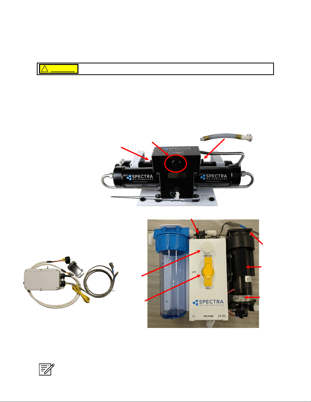
Front View
Double rubber mounts
to absorb vibraon
The Clark Pump Membrane
Module comes pre-mounted
and plumbed together as a
single unit. The combined unit
saves me and adds
reliability.
Ventura Feed Pump Module
Includes the feed pump, cooling fan, charcoal lter, ush valve,
service valve, and service port. The module has compact and
streamlined plumbing. The cooling fan is included for longevity.
Pressure Relief Valve
Always maintain enough reserve water to get safely into your next port.
CAUTION !
Note: If your system came with the oponal Z-Ion, the Z-Ion unit will replace the
charcoal lter housing. The photo above, and all subsequent photos of the Feed
Pump Module, will look slightly dierent.
Fresh Water Flush Solenoid
Inlet
Service
Port
Service
Valve
Cooling
Fan
Shuro
Pump
Heat Sink
**
Brine Discharge ng to
facilitate maintenance. Can
be ed to either side of
the Clark Pump**
10
Components
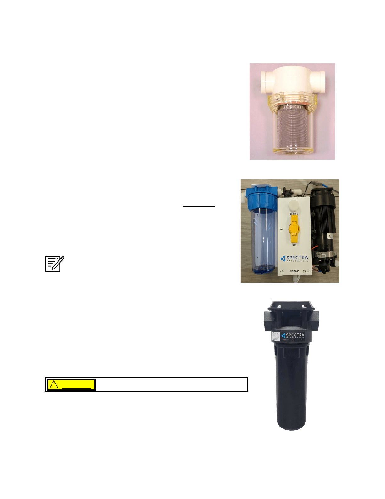
Sea Strainer Mount close to the intake through-hull, in a
locaon that can handle water spillage during service.
5 Micron Prelter Bowl Locate in an area that allows easy
access as this will be the most frequently serviced module while
cruising. Mount vercally and leave room below bowl for lter
changes.
Do not mount above water-sensitive equipment.
CAUTION
!
Feed Pump Module
Mount the feed pump module on a vercal surface, no more
than 3-feet (1.0M) above the waterline. It is preferable to
mount as low as possible. Locate in an area that allows easy
access to the charcoal lter, and the service valve. Keep
future maintenance in mind when choosing a locaon, and do
not mount above water-sensive equipment.
NOTE: IF INSTALLING THE Z±ION, SEE Z±ION
INSTALLATION INSTRUCTIONS FOR MORE DETAILS.
11
Components - Cont.
Double rubber mounts
to absorb vibraon
This module must be installed in an area that maintains a temperature below 113°F (45°C). It
may be placed as high in the boat as you desire, and mounted in any posion, even upside
down. Make sure that the area around and under the pump does not have any water sensive
equipment, as water will be spilled during any repairs or if a leak occurs. Allow for easy access
to the pressure relief valve.
The Clark pump and membrane module comes complete with a mounng system. Be sure to
use the supplied washers on the rubber feet.
Pressure Relief Valve
Clark Pump and Membrane
Remote Manual Controller
The remote control panel can be mounted anywhere dry and
convenient. Cut a 5/8” (1.5 cm) wide by 5/8”” (1.5 cm) high
opening for the display port. The display needs minimum 2
1/2” deep clearance for the cable. Take care not to damage
the plugs on the ends of the cable when roung.
Templates for mounng the Remote Controller Bezel and
fabricang a backplate for the Bezel can be found on pages 59
& 60.
Note: Use only a Spectra-approved cable.
12
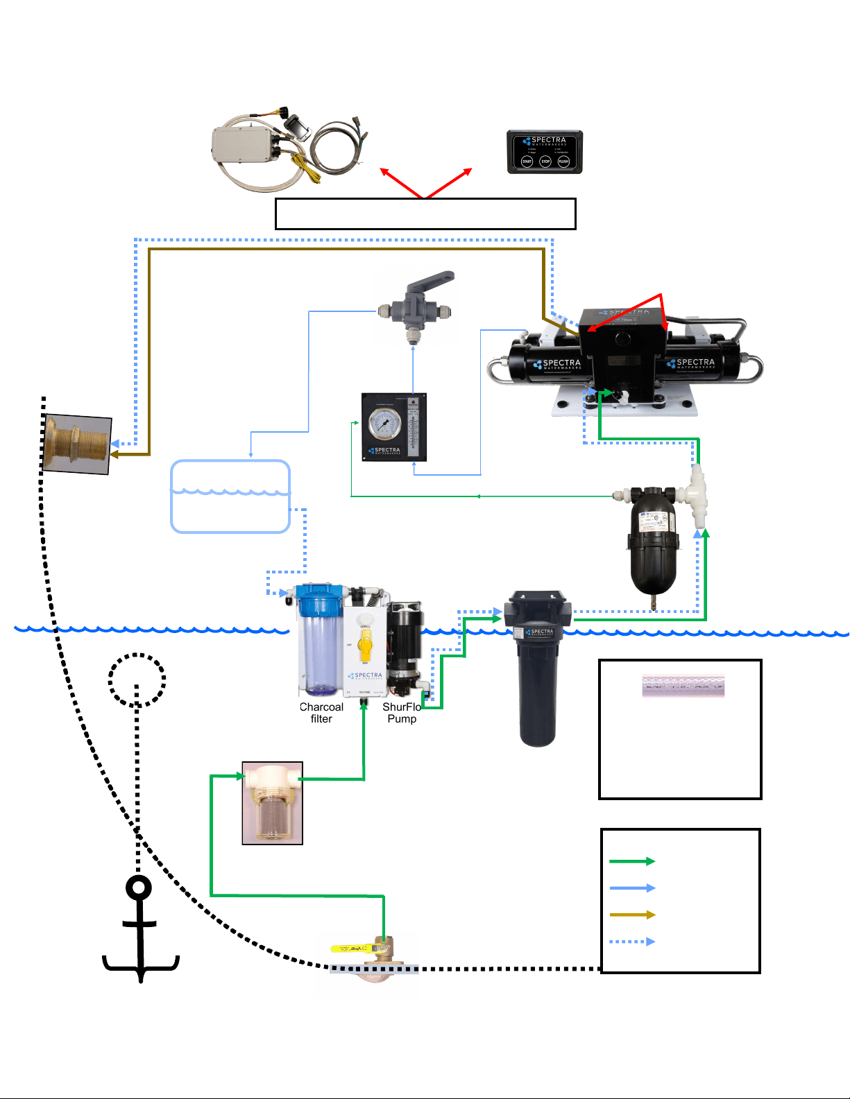
ShurFlo
Pump
Charcoal
filter
Freshwater Storage
tank
(Inside Boat)
(Outside Boat)
Feed
Water
Inlet
Feed
Pump Module
Brine discharge thru
hull (not included):
place above waterline
or tee into another
visible drain.
(Pressurized
Fresh Water)
Ocean Feedwater
Legend:
Drinkable Freshwater
Brine Discharge
Freshwater Flush
Note: Brine discharge may be
connected to either side of Clark
Pump
Use the supplied 5/8-inch
(15.9mm) clear braided vinyl
hose for all runs. More hose may
be ordered from Spectra, or
bought at a hardware or marine
store.
Simplified Plumbing Layout
Water-sensitive Equipment.

13
Installation Notes
14
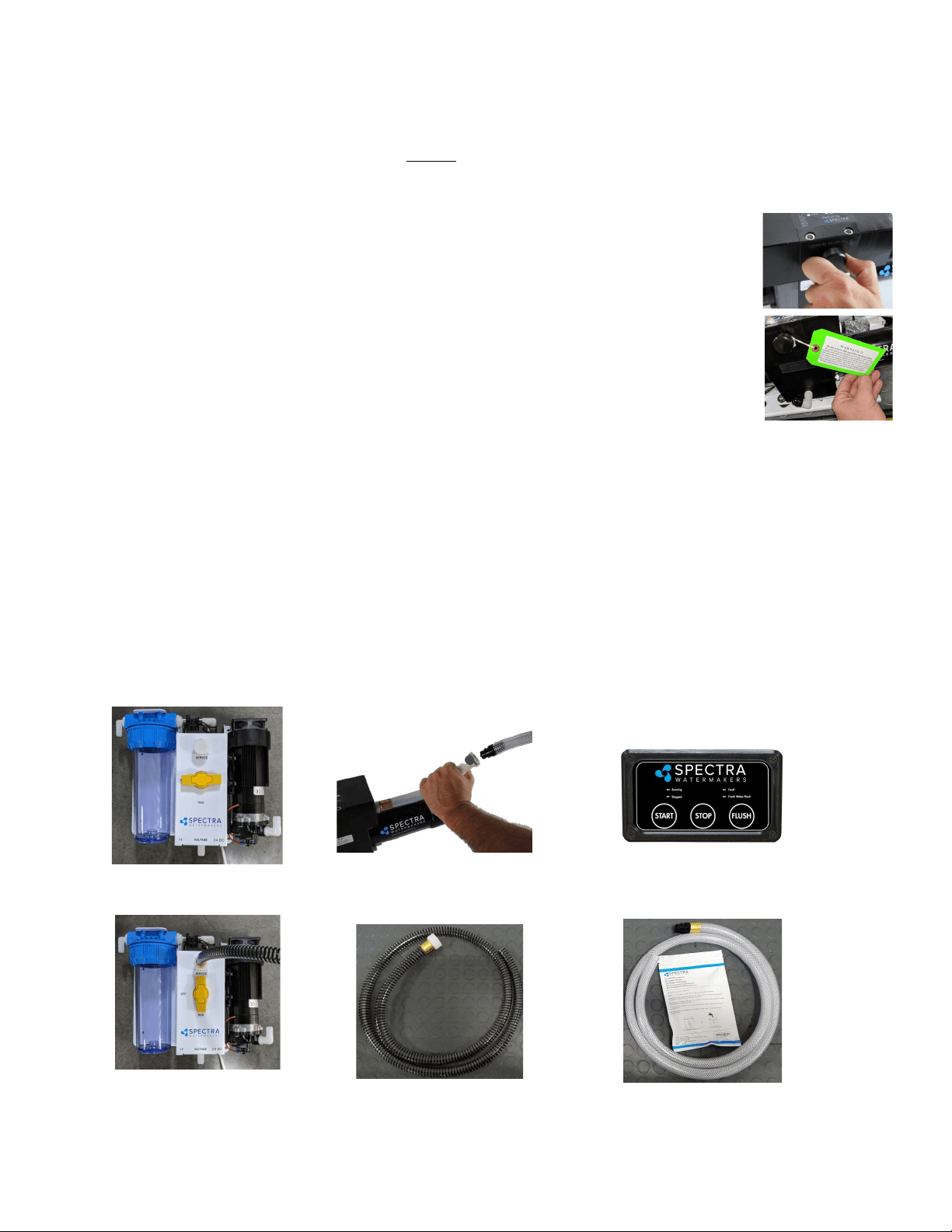
Product output ng.
Back view of instrument panel
Use accumulator port to connect the
pressure gauge with the supplied 1/4”
black nylon tubing. Tubing must be
pressure rated to 150 PSI (10 BAR).
Product Flow Meter
Pressure Gauge
Product Water Plumbing and Pressure Gauge Tube Installation
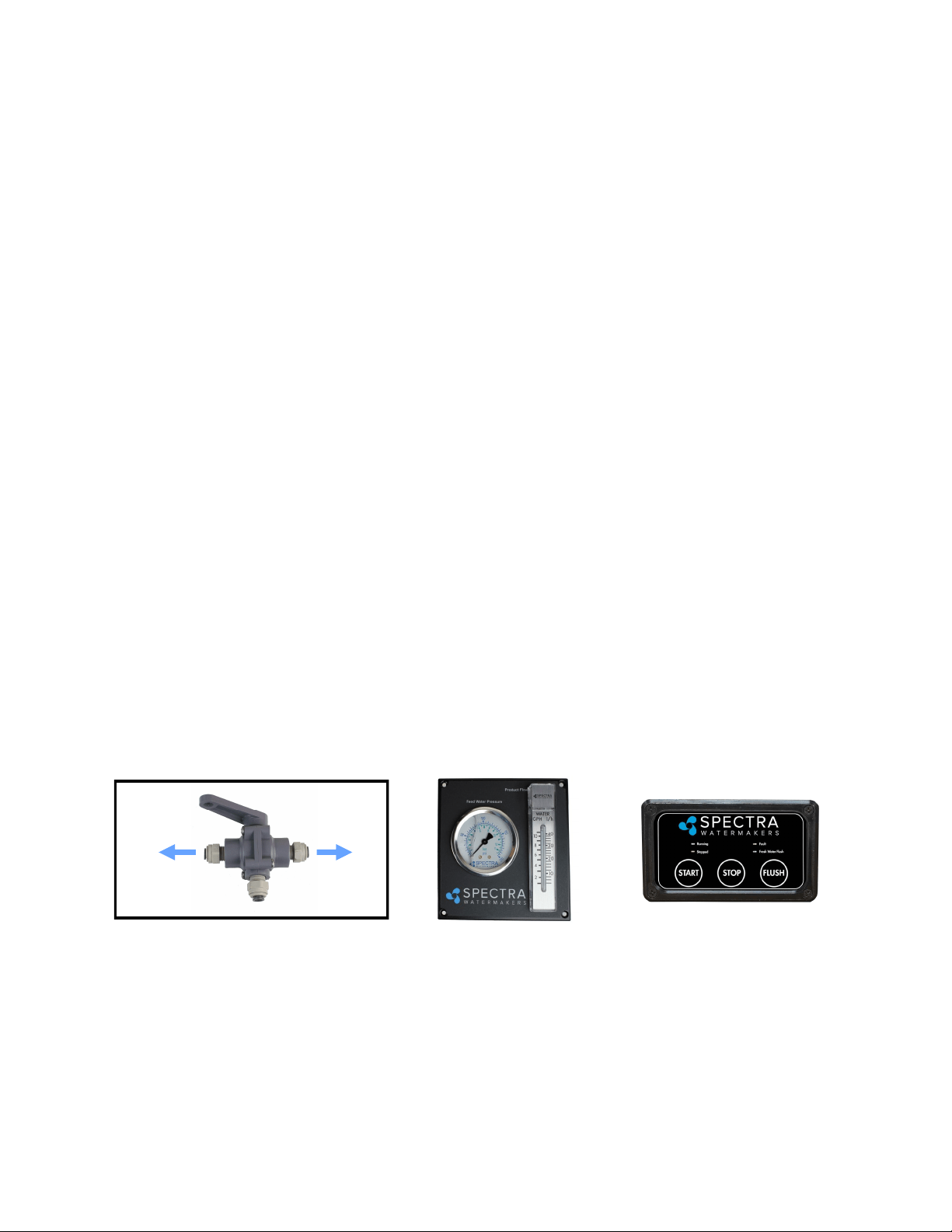
Product Sampling Valve: Mount using the
supplied plasc straps. Note: the handle points
in the direcon of ow.
Product to tank: Route the product water
from the valve into the top of a vented
tank. Install a tee in the water ll or tap a
pipe thread into an inspecon port.
DO NOT! feed the product into a
vent line, manifold, or the boom
of the tank. Make sure that there is no
restricon in this piping. Pressure in the
product tubing must never exceed 5psi
(.3bar), running or stopped, or the
membrane will be permanently damaged.
Sampling Tap for tesng the
product water.
Use the supplied 1/4”
black tubing for the
product water plumbing.
!
15
16
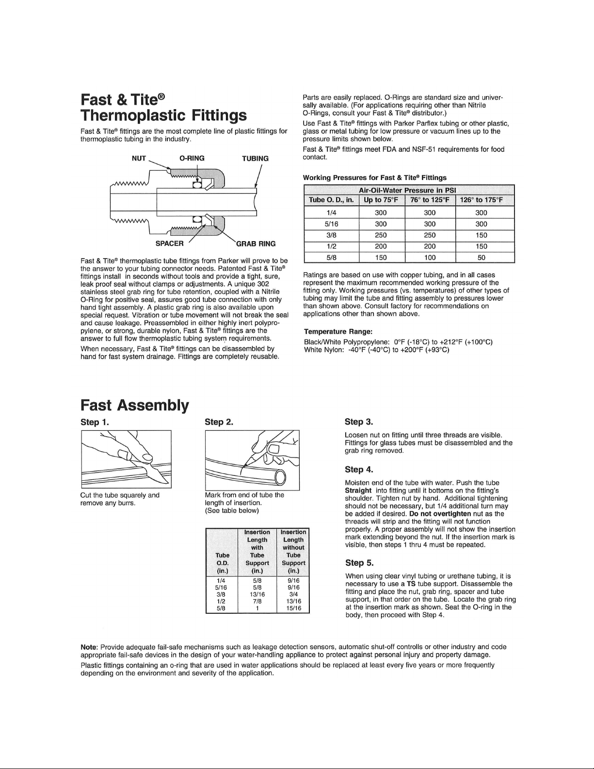
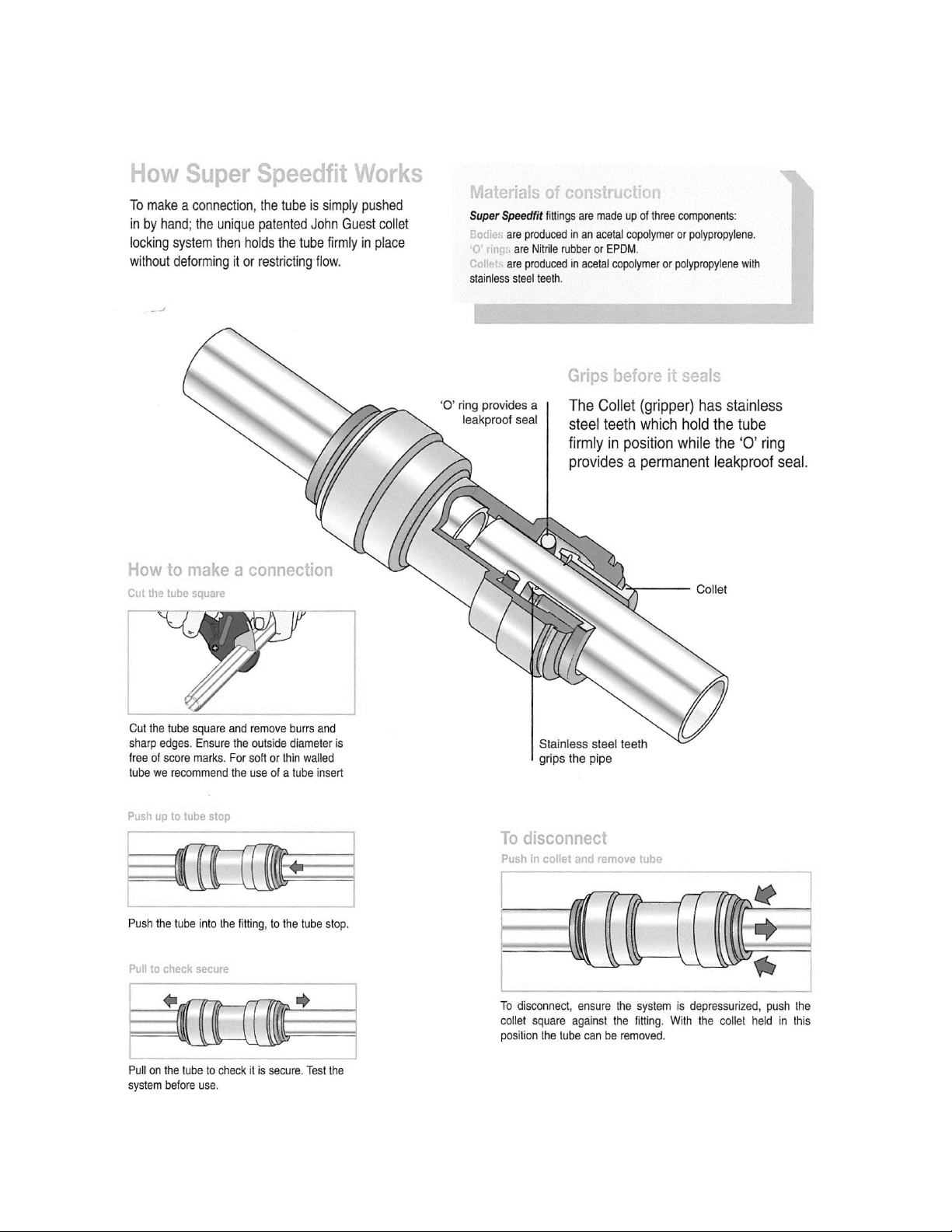
John Guest Super Speedfit Fittings
17
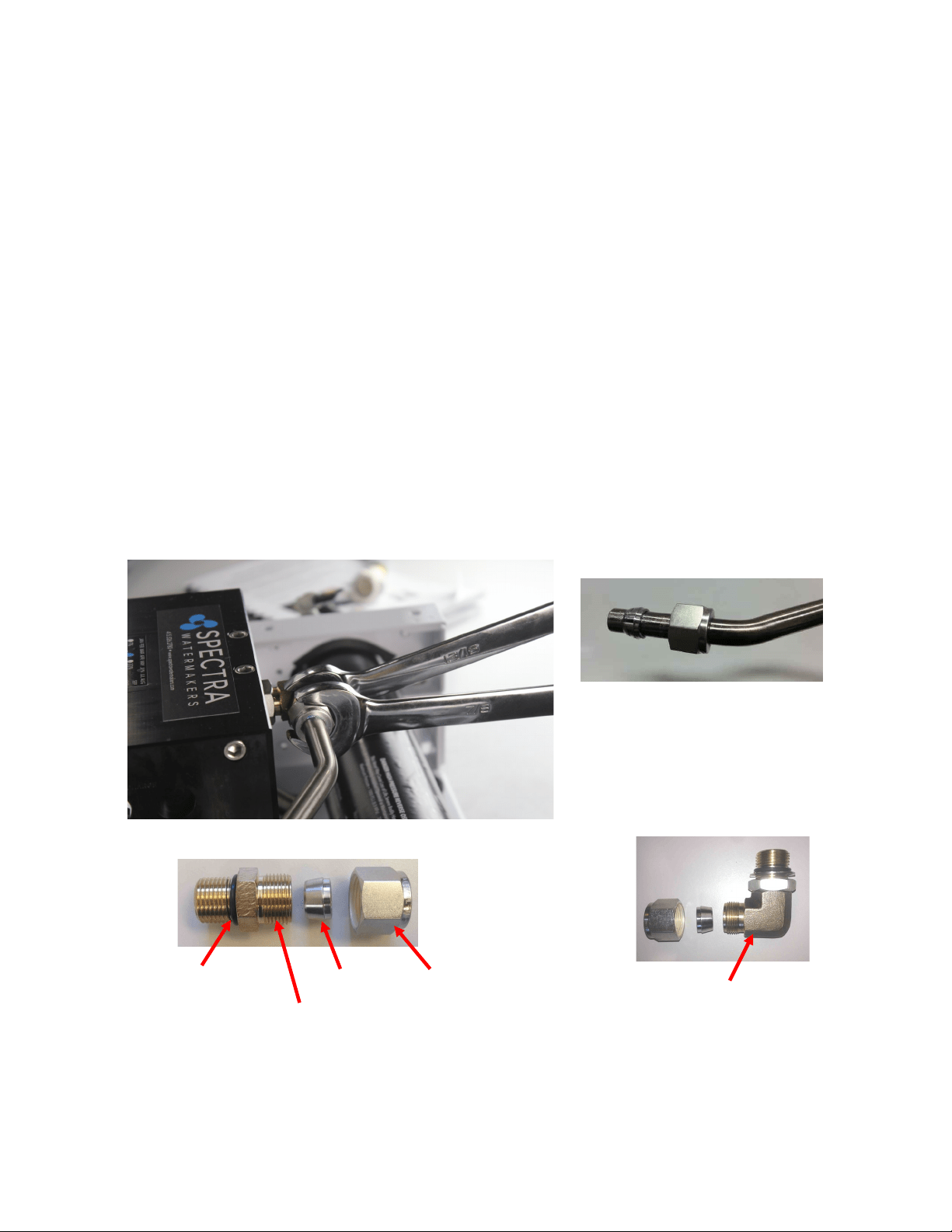
Spectra High Pressure Fitting Instructions
The Ventura has eight high pressure ngs, two on each cylinder on the Clark Pump, two on
the pressure vessel end caps, and two 90-degree elbows on the back of the Clark Pump. As the
compression ng is ghtened, it compresses a ferrule onto the stainless tubing, xing the
ferrule permanently to the tube and holding the compression nut capve.
The body of the ng seals to the underlying component with an O-ring. On the Clark Pump
cylinders and the end caps this O-ring is compressed by ghtening the enre ng. The O-
rings on the 90-degree ngs on the back of the Clark Pump have capve nuts and washers,
which compress the O-rings without turning the enre ng.
If a tube ng leaks it can somemes be resealed by just ghtening. You must use two
wrenches, a 13/16-inch wrench to hold the base, and a 7/8-inch wrench to turn the
compression nut. The 13/16-inch wrench will need to be thin so as not to interfere with the
compression nut. If this doesn’t work, disassemble the ng, grease liberally with silicone
grease (the ferrule and the threads) and re-ghten rmly.
The base O-rings should be gently compressed to achieve a good seal, and may be damaged
by overghtening.
Stainless Fing Hex Nut
Connector O-RING
Nickel-Bronze High Pressure Elbow
Nickel-Bronze High Pressure Straight Fing
Ferrule
18
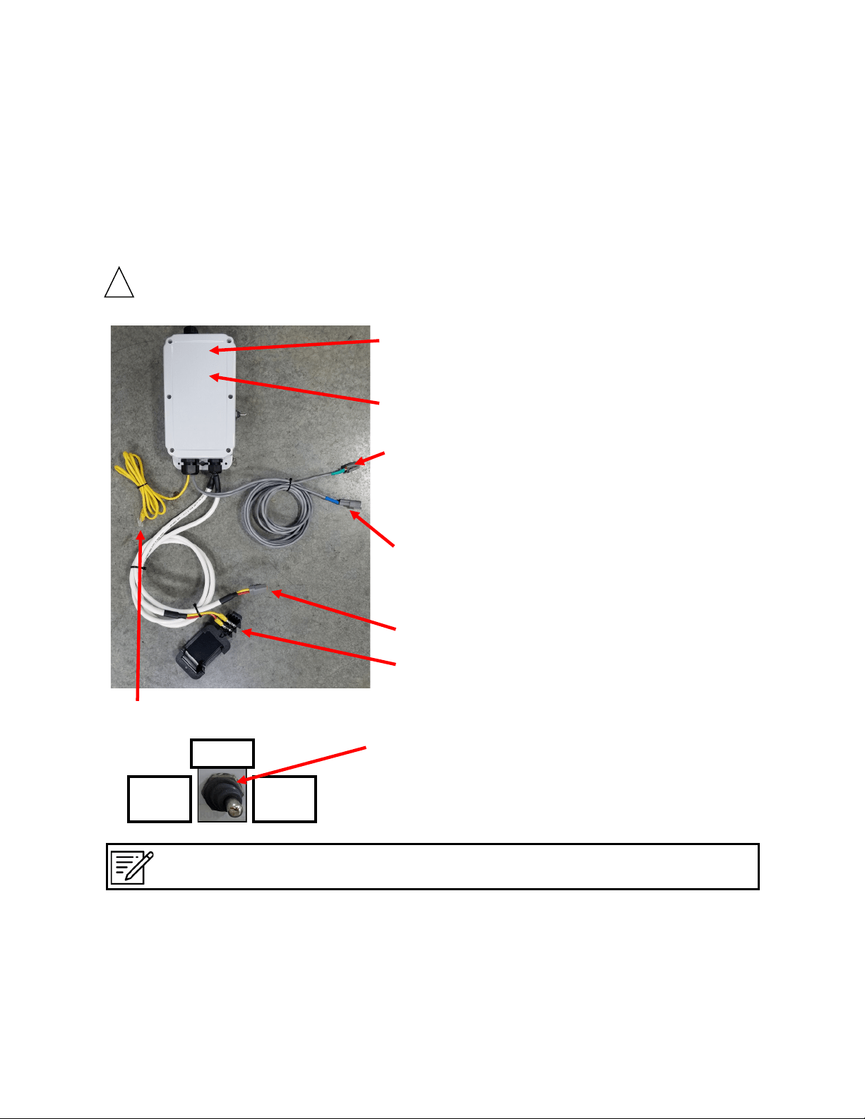
Ventura Remote Manual systems are pre-ed with waterproof connectors for electrical and signal
cables. Each connector is dierent, so it is impossible to connect them incorrectly, and the connectors
are color-coded. The system has a power inlet harness with a terminal block and cover, Pump Power
cable, 2–conductor fresh water ush solenoid cable, a Z-Ion power and signal cable, and a 5-foot cable
for the Remote Manual Controller.
Do not install it in hot or poorly venlated locaons.
Power Inlet Harness with terminal block
Spectra Remote
Manual Control Box
Circuit Board (Inside
Control box)
Run Manual/Standby/Run
Auto - Toggle Switch
Electrical
Z-ION Connector (with green band). Le
unused if your system was not ordered
with the oponal Z-ION upgrade.
Standard Fresh Water Flush connector (Blue)
Feed Pump Power Cable
Spectra Remote Control Cable
!
Note: The middle position on the toggle switch labeled “Standby” means the system is still receiving
power, but the system itself is not actually running.
Run
Manual
Run
Auto
Standby
19
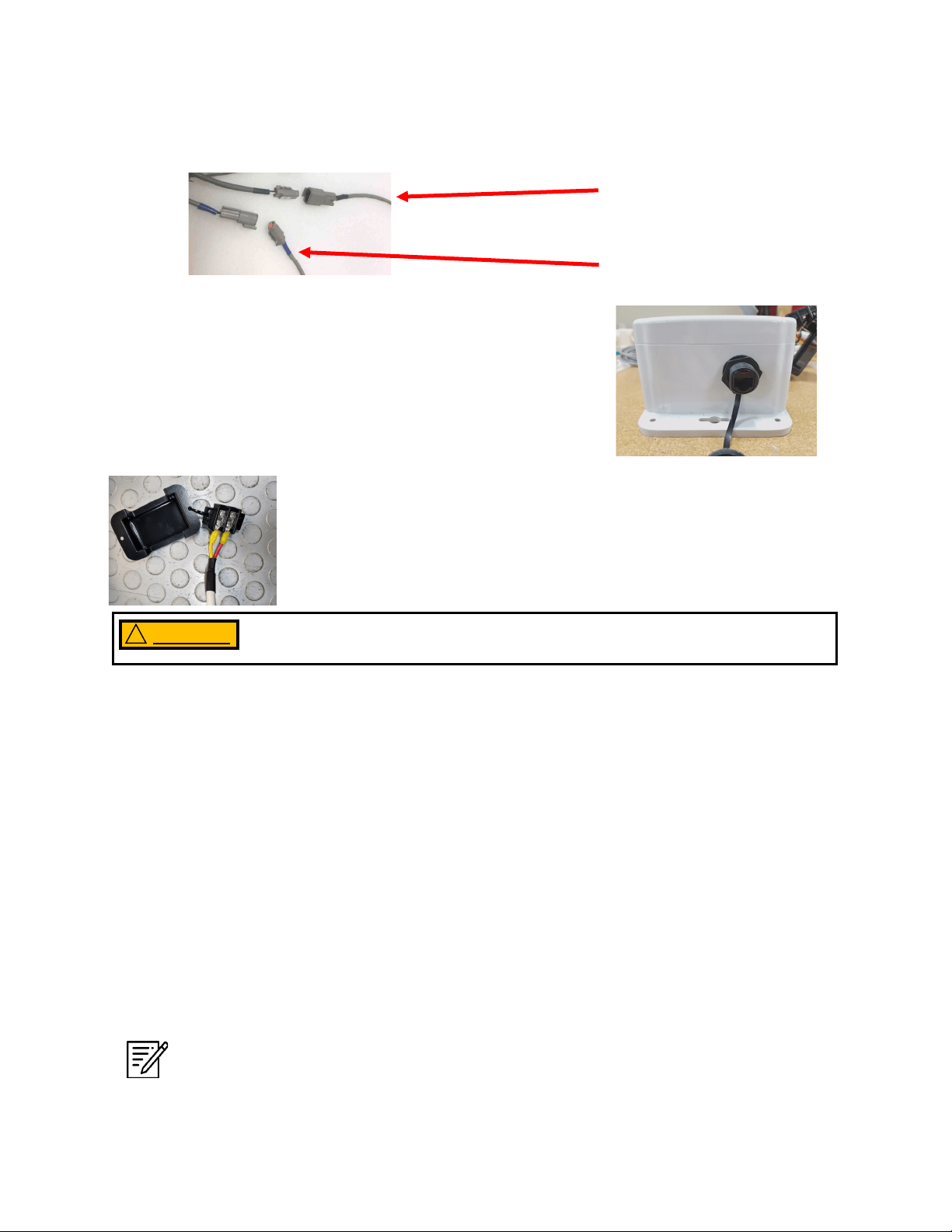
The Ventura Remote Manual has one external port which is
reserved for the customer to set up a local display if
desired. The recommended display cable is a standard Cat
5e ethernet cable.
Electrical - Cont.
Wire Size Guide for the Ventura 12V:
Protect with 15 Amp Fuse or Circuit Breaker
10 Gauge (5mm²) up to 15 feet (4.5M)
8 Gauge (8mm²) up to 25 feet (7.5M)
6 Gauge (13mm²) up to 35 feet (10.6M)
Note: If the specied circuit breaker sizes are unavailable, use the next higher rang
but do not exceed the specicaon by more then 10%. All wiring to be done to
applicable ABYC, Marine UL, or CE standards.
Distances at le represent the total
ROUND TRIP wire length (DC posive
length plus DC negave length), NOT
the length of the pair of wires
together. Size cables accordingly.
Mount the main power terminal block in a juncon box or on a bulkhead
adjacent to the feed pump module. Make sure that this is a dry locaon
well above bilge level and not subject to water spray. Be sure to install
the terminal block cover.
Check the wire size chart for appropriate wire sizes. DC power feeds should be uninterrupble
to ensure proper operaon. Avoid house breaker panels that could be accidentally tripped.
Oponal Z-Ion power and signal
cable (3-conductor, Green)
Fresh water ush solenoid
cable (2-conductor, Blue)
Do not apply voltage to the unit that exceeds 14.6 VDC. Serious damage to
the electrical system may occur.
WARNING !

20
Wiring
Important: Mount the control box with 4 appropriate fasteners on a vercal surface, above
components containing water, with the wire grommets down, and central to the other system
components. Make sure the cables will reach all of the modules to avoid splices. The main
power feed should come from an appropriately-sized fuse or breaker on the main DC panel.
See wire size and fuse/breaker tables below.
Do not connect the main power feed unl all other connecons are made.
WARNING !
21
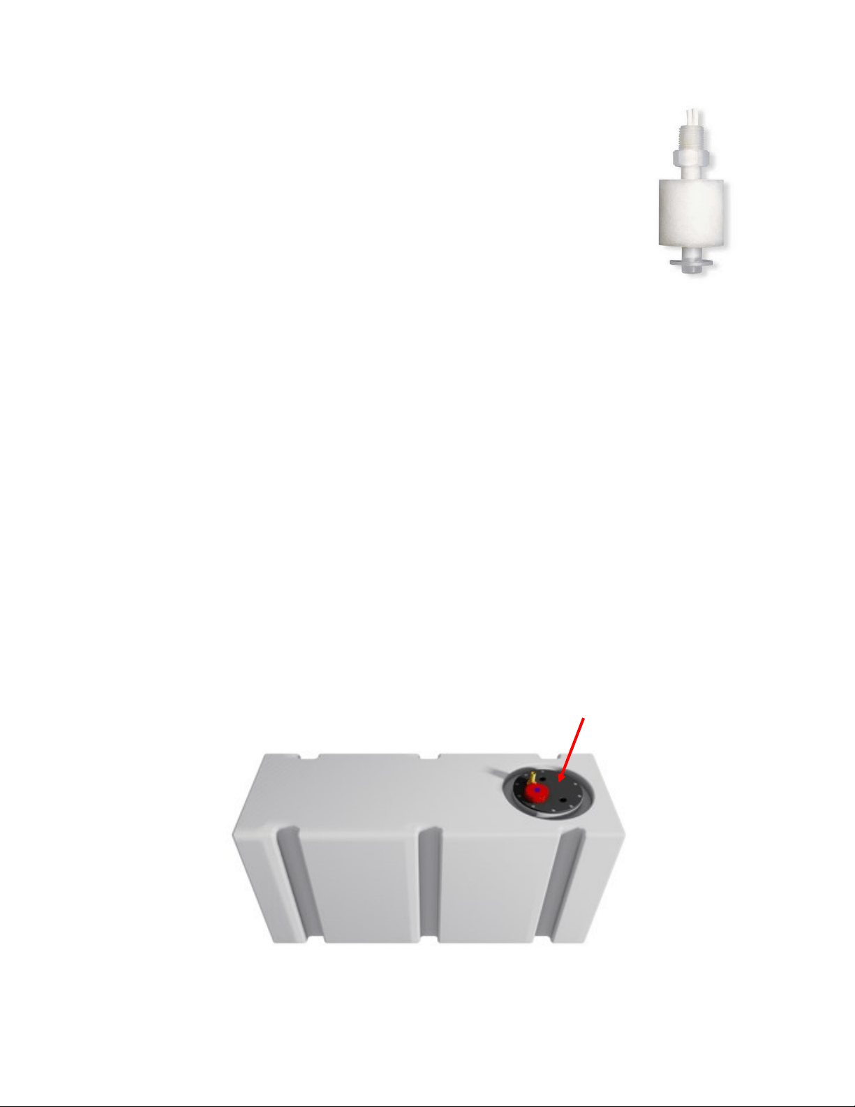
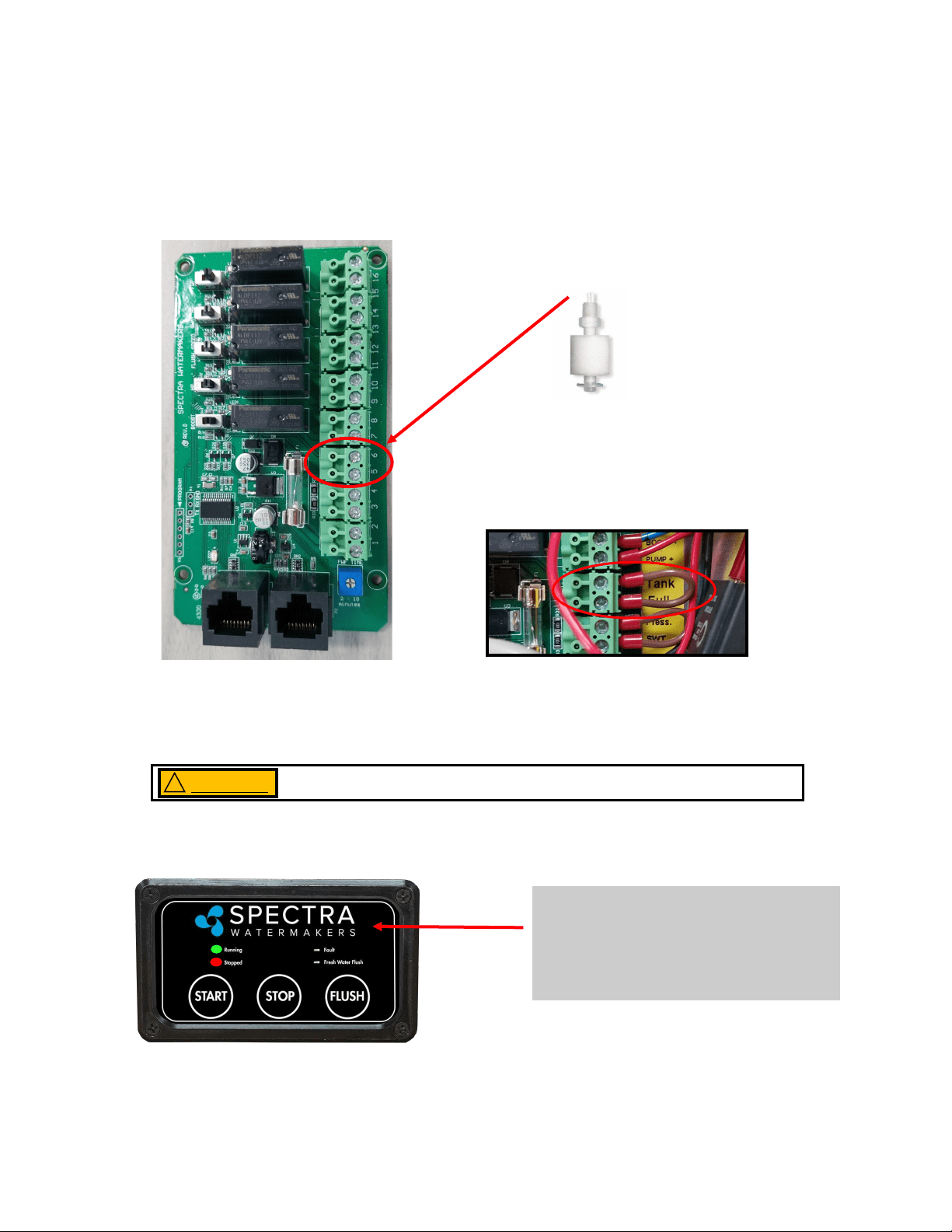
Customer-Supplied Tank Full Switch
Installing an oponal tank full oat switch at the top of your water tank
allows the watermaker to ll your ship’s water tank then automacally stop
running. The user can then fresh water ush with by hing ’Stop’ and then
’FWF’ on the Remote Controller.
Your watermaker does not come with the top-mounted Tank Full Switch (EL
-SWT-LV). However, this part can easily be sourced from your local dealer or
Full Service Provider if you wish for your system to automacally stop once
your freshwater tank is full.
If you do not install the Tank Full switch in your tank, you MUST MANUALLY STOP the system
when your freshwater tank has been lled. The system will not stop automacally.
Note: The oat may need to be ipped 180 degrees to work properly. Many oats can be
easily ipped by removing the clip opposite the wire.
Optional Tank Switch
Drill and Tap
Drill and tap a 1/8” NPT port into the top of the fresh water tank that is being lled by the
watermaker. This can be installed on a tank access cover, or directly into the water tank. If
installing on an access cover, be sure to leave a service loop on the oat switch wiring to allow
removal of the tank access cover.
22
Watermakers should never be run unaended.
Tank Full
If a tank switch has been installed, the
“Running” and “Stopped” lights will be
illuminated when the tank is full and the
system will stop.
Your watermaker should never be left running unattended.
WARNING
!
Optional Tank Switch - Cont.
The customer supplied oat switch must be connected to the Terminals 5 & 6 labeled Tank
Full within the Control Box that is mounted to the inside of the Feed Pump Module. There is
no polarity. Remove the jumper. Connect the wires to the terminals.
Use 18/2 nned wire or larger. Wire is not included in the installaon kit.
Connect to
Terminals 5 & 6
Note: Remove only the jumper in terminals 5 & 6.
23
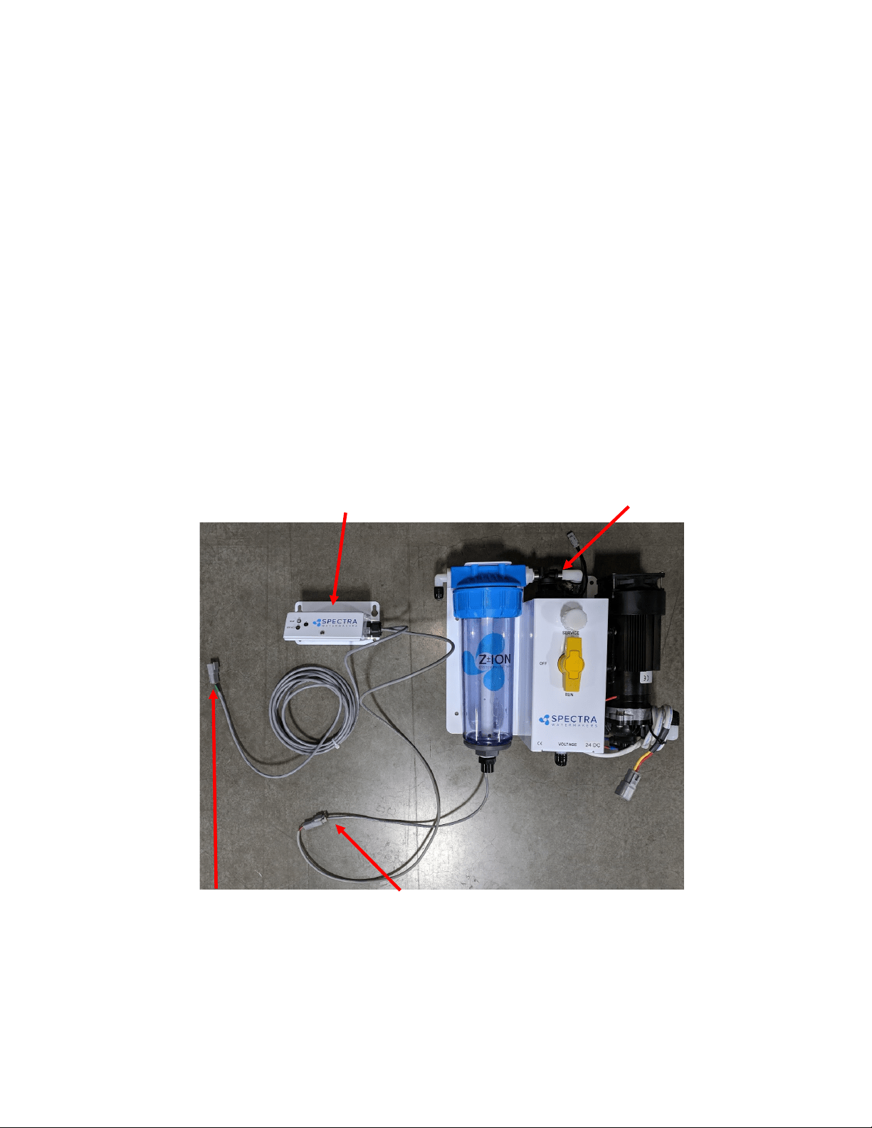
Optional Z-Ion Installation
The Z-Ion replaces the fresh water ush module on the feed pump module. The Z-Ion lter
bowl, like the normal fresh water ush module, houses the charcoal lter, which must be
replaced every six months.
The Z-Ion control box comes with four-foot cables for exibility in mounng on the bulkhead
above or adjacent to the feed pump module.
Plug the connector from the Z-Ion generator bowl into the connector from the Z-Ion control
box.
Connect the power/signal cable, marked green, from the Z-Ion control box to the Z-Ion control
cable, also marked green, coming from the Spectra Connect box.
Solenoid valve (opens during fresh
water ush/Z-Ion treatment)
Z-Ion control box
Connector to generator
bowl (2-pin)
Connector to Spectra Connect
control box (3-pin, labeled green)

24
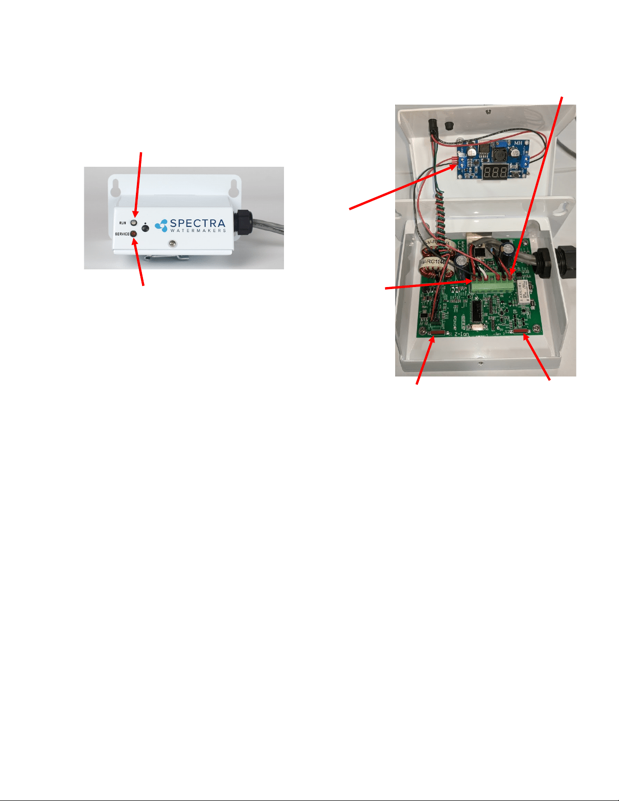
This revoluonary adaptaon of an ancient technology eecvely and safely protects the
membrane and lters on your Spectra Watermaker from biological growth. Your system will
be kept ready to operate without any addional ushing, external power sources, pickling
chemicals, or complex procedures. The controller has been specically designed to batch
process (produce) metallic ions for system disinfecon.
The process has been around for many years, however most systems produce ions on a
connuous slow basis rather than a short intermient process. We found that the most
stable way to produce ions in a batch process is to maintain a constant current to the
electrodes and vary the voltage. By being able to boost the voltage the amount of electrode
surface area can be smaller to produce the needed ions in a brief period of me.
The Z-Ion should be energized at all mes, but will only consume power when water is
running through it. Upon inial power-up the LED will ash red/green and then will turn solid
green.
Follow the instrucons for Normal Operaon and Fresh Water Flush (for treatment with the Z
-Ion, the process is idencal, only the Z-Ion will release silver and copper ions into the ush
water.)
When fresh water ows, the operaon cycle begins and the LED turn o, and only quick
ashers of green and amber. The cycle will connue unl either the ush cycle stops or the
adjustable mer mes out (factory set for 15 minutes).
If the voltage is out of range, below 10V or above 56V, the LED will ash red every two
seconds and the unit will shut down.
Each fresh water ush with the Z-Ion will protect your watermaker for up to 30 days, aer
which the process must be repeated.
Aer 720 cycles the service light on the front of the control box will light up, indicang that
the probes on your Z-Ion may be wearing down, and should be tested. The service light is just
a reminder that your Z-Ion rods need to be inspected. Before reseng check that rods have
not dissolved and are not touching.
To reset the service counter, touch two magnets, at the same me, to the two red reed
switches on the Z-Ion circuit board, labeled Switch 1 and Switch 2 on the following page.
Z-Ion Operation and Installation
25
Switch 1
There are 7 pins on the phoenix connector from le to right:
Pin 1 Supply Voltage-Baery ( + )
Pin 2 Ground
Pin 3 Trigger
Pin 4 Auxiliary Output 1
Pin 5 Auxiliary Output 2
Pin 6 To ion generator (bowl). No polarity.
Pin 7 To ion generator (bowl). No polarity.
Auxiliary Outputs 1 and 2 are switched to the supply voltage when turned on. These outputs are protected by 100mA
self reseng fuses.
Output 1 – ON during generang cycle – intended to drive a pump relay on some systems
Output 2 – ON when cycle counter reaches pre-programmed number (usually 720), when generator element may
need replacement and should be tested and/or inspected.
Operaon – LEDS
Power-up indicaon – fast red/green ash for a few seconds
Ready, Idle – solid green
Generang – the LED will quickly ash at a programmed interval (factory set to 17 seconds between ashes.)
The ash color with alternate between green and amber and will be o in between voltage spikes. The
color change symbolizes the polarity alternang from posive to negave.
Bad power – fast red ash followed by shut down
High temperature – fast red ash
Cycle counter reached limit—slow red ash
Switch 2
Pin 1
Pin 7
Run Light
Will be green when while Z-Ion is
powered and ready
Service Light
Figure 1
Voltage
Spike Counter
Z-Ion Layout and Specs.

26
Operation

27
28
New System Start-Up and Testing
Avoid running the Ventura system if the vessel is in contaminated water. The system should be fully tested before
leaving port. If the locaon or weather prevents proper tesng, refer to Dry Tesng with an Arcial Ocean on
page 28.
Every new system is shipped from the factory with nontoxic, food-grade propylene glycol. Propylene glycol,
Spectra Chemicals, or anything other than seawater or freshwater must be purged from the system with the
pressure relief valve open at least 1/2 turn. You can purge your system with seawater or with freshwater via the
system’s freshwater ush funcon. The system must be purged for a minimum of 60 minutes, or unl at least 40
gallons of water have moved through the system.
***When purging SC-1 from a pickled watermaker, system must be purged for a minimum of 20 minutes.
Propylene Glycol should be purged for minimum 60 minutes***
Warning! Damage may occur if the purge sequence is bypassed and the membrane is pressurized with
storage chemical in it.
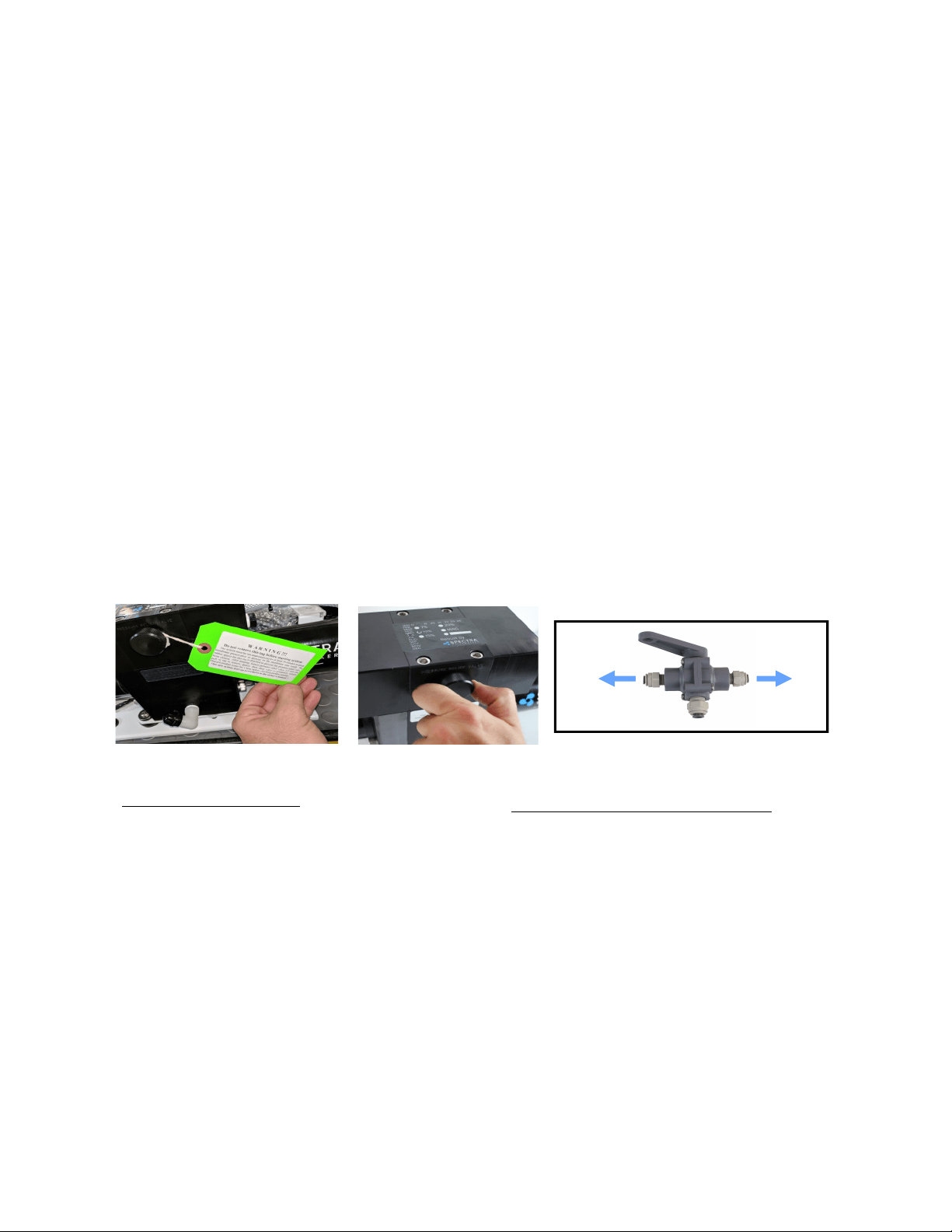
1. First, check that:
• Thru-hull inlet and the brine discharge valves are open.
• All of your hose connecons are ght.
• The washer with the green tag under the pressure relief valve has been removed.
• The pressure relief valve is open at least 1/2 turn.
• The sampling valve is set to the sample posion
• The brine line is able to freely discharge
Open 1/2 Turn when
purging chemicals!
Remove Tag and Washer!
For a purge with seawater
• Move to an area free of contaminated water,
such as in a polluted harbor or canal.
To Sample
To Tanks
For a purge using the freshwater flush
• The vessel’s pressurized water system
is on
2. Turn on feed pump via the manual toggle switch and check to make sure water is coming out of
the brine discharge (thru-hull above water).
3. Run the system without pressure for 60 minutes to purge the storage chemicals. The pressure
gauge should read less than 35 PSI. If purging with freshwater, the sampling tube may discharge wa-
ter.
4. Close the pressure relief valve. The pressure should rise to 60-80 PSI (4.2-5.7bar) on a Ventura 150
and 80-90 PSI (5.5-6.5 bar) on a 200T. Water should begin to ow out of the sampling tube. If the
ship is located in brackish or fresh water, the pressure will be lower.
Depending on storage and environmental condions the system may need to have addional purging
me. If the product water does not taste pure or sample at below 500 ppm, purge or run the system
for up to 6 addional hours.
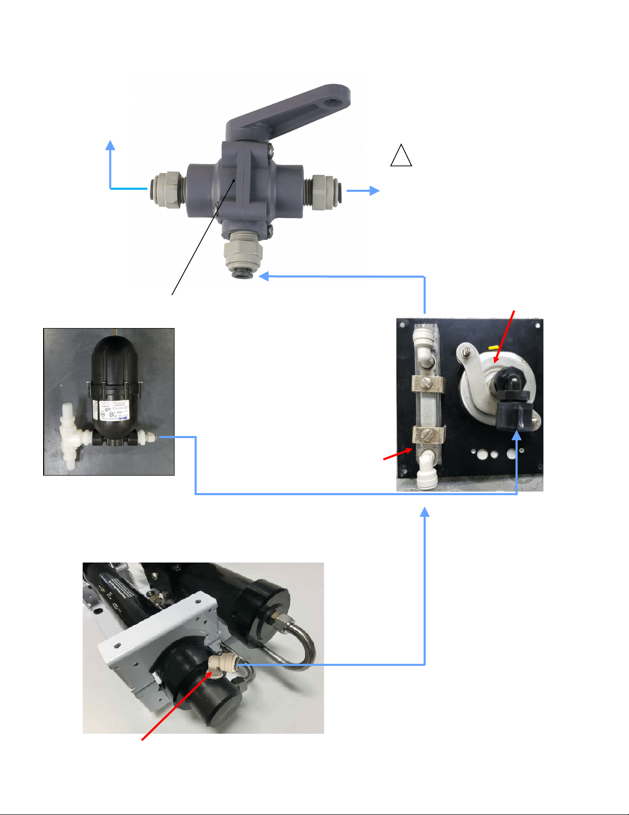
3-Way Sampling Valve
29
If the system has been pickled, stored, or contains cleaning compounds, use the New System Startup procedure.
The system should be fully run tested before you leave port. If the locaon or weather prevents proper tesng refer to
“Tesng with an Arcial Ocean.”
THE VENTURA 200T IS DESIGNED FOR WARM WATER USE. OPERATION IN WATER BELOW 50 DEG F (10
DEG C) MAY CAUSE HIGH OPERATING PRESSURES AND INCREASED WEAR
1. Check that the thru-hull inlet is open.
2. Turn the product sample valve to the SAMPLE posion.
3. Turn the yellow service valve handle on the feed pump module to RUN.
4. Start the system by pushing ‘Start’ and check for ow by inspecng the brine discharge and checking
for pressure on your analogue gauge. If there is no ow, open the pressure relief valve on the Clark
Pump to prime the system and bleed the air out of the feed pump.
5. Aer 5 minutes, check the product water with your handheld salinity tester. When it is below 750
PPM, divert the product into your tank by rotang the product sample valve handle 90 degrees.
6. Run the system unl you have lled your tank or have made enough to meet your requirements.
7. Following your water making session, perform a freshwater ush.
Freshwater Flush (You should freshwater ush your watermaker aer EVERY use.)
1. Push the Freshwater Flush buon on the remote panel.
2. The freshwater ush solenoid will open and feed pump will come on, allowing pressurized freshwater
to ow through the system. Pressure will drop on the gauge, which indicates that the membrane is
ooded with fresh water.
3. Aer a proper ush, the ppm of the brine discharge should be below 1000ppm.
You may now leave the system unaended for up to ve days (30 with the Z-Ion) without further aen-
on.
Remember that you need to run the system almost a half an hour to make enough water for a ush. You
Normal Operation and Fresh Water Flush
Analogue Gauge
Panel
Remote Panel
3-Way Product
Sampling Valve
To Sample
To Tanks
30
If it is not possible to test run the system with the boat in the water, you may test the system with an arcial
ocean. You will need 1.3 lbs. of non-iodized salt (rock salt, sea salt, or aquarium salt) to make a 5 gallons (33 grams
of salt per liter) of water that is about 33,000 PPM salinity (average seawater salinity). Make sure the domesc
water system is powered up and the boat’s tank has at least 60 gallons (230 Liters) of water to purge the storage
chemicals from the system. Conrm that the charcoal lter is installed in the feed pump module, and the domesc
water line is connected. If freshwater system is not available & system is sll pickled, alter beginning procedure to
feed unchlorinated water through the service port to purge out storage chemical.
1. Open the pressure relief valve on the Clark Pump. Remove the green tag and spacer, if sll
aached.
2. Press the Freshwater Flush buon to run a full ush cycle. If there are storage chemicals in
the system, ush for addional me to purge out chemicals. SC-1 minimum 20 minutes purge,
Propylene Glycol minimum 60 minutes purge.
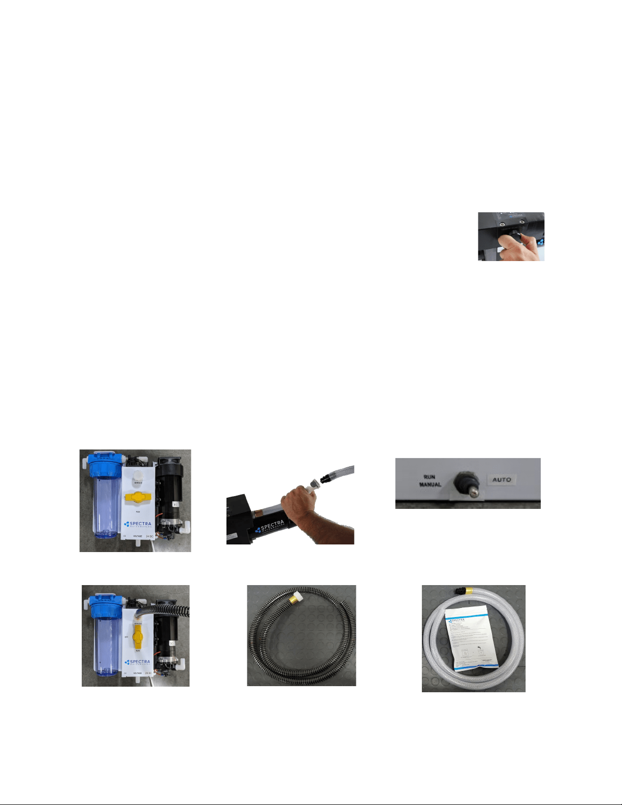
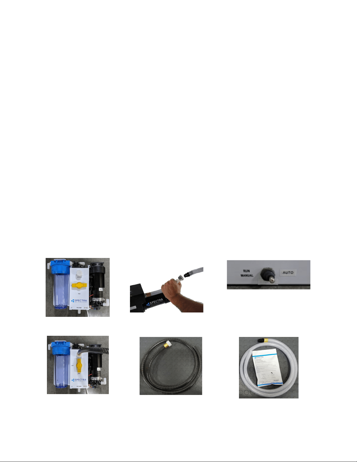
3. Connect the black spiraled intake service hose** to the service port on feed pump module,
then connect the vinyl brine discharge service hose* to the quick disconnect ng on Clark
Pump. Refer to the photos below. Route both hoses into the 5 gallon (20 Liter) container. Turn
the product sample valve to the sample posion, and route the product into the bucket.
4. Using the remote panel, select Freshwater Flush. Run unl the bucket is lled.
5. Turn the yellow valve to SERVICE.
6. Mix salt with the freshwater to the proper proporon or use an aquarium hydrometer to adjust the
salinity level.
7. Push the Start buon to run the system.
8. Allow the system to prime and then close the pressure relief valve. The system should build pressure
shortly and start making water, with the brine and product water recombining in the bucket to be
cycled again. This will gradually heat the water. Do not let the water temperature exceed 120 deg. F
(49 deg. C).
9. Run the system under pressure, checking for proper operaon and leaks. Aer tesng the system, re-
install the brine discharge hose, product tube, and freshwater hose from the strainer. You can now
ush the system by pressing the Freshwater Flush buon.
**Intake service hose con-
nected and yellow service
valve handle to SERVICE
*Connecting brine discharge
service hose at quick disconnect
Service valve OFF, in FLUSH
position
**Black spiraled rein-
forced intake service
hose
*Vinyl Brine Discharge Ser-
vice Hose
Remote panel
Dry Testing with an Artificial Ocean

31
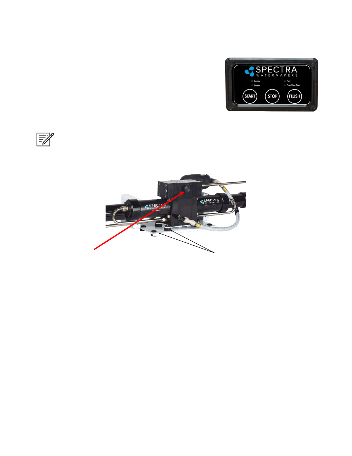
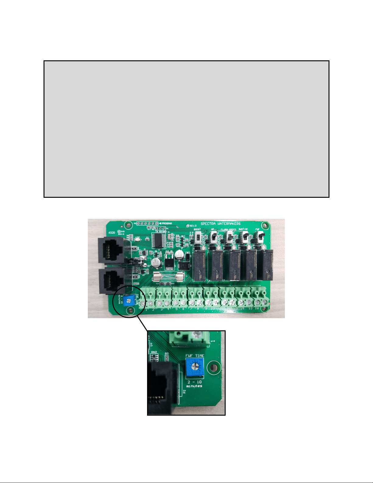
Start
Pressing the ‘Start’ buon begins watermaker
operaon.
If the system has been pickled, winterized, this is the rst startup, or the condion of the system is
unknown, go to NEW SYSTEM START-UP on page 28 or serious damage may occur.
A fresh water ush should be performed aer every use of the watermaker. The system will need
to run for approximately half an hour to make enough fresh water for one ush.
Fresh Water Flush (FWF)
Pressing the ‘Fresh Water Flush’ buon oods
the watermaker with fresh water from the
vessel’s domesc water tanks. Opens solenoid
valve to allow water to ow from tank instead of
seawater from the thru-hull. Fresh Water Flush
mode will end automacally aer ush is
complete, approximately 3 minutes.
Stop
Pressing the “Stop” buon ends watermaker opera-
on. The “Stop” buon must be pressed before
beginning a Fresh Water Flush.
Fault Light
The “Fault” light indicates that there is a
problem with the system, usually caused by
too much or too lile pressure in the feed
water or membrane pressure vessel.
Spectra Manual Remote Controller Guide
32
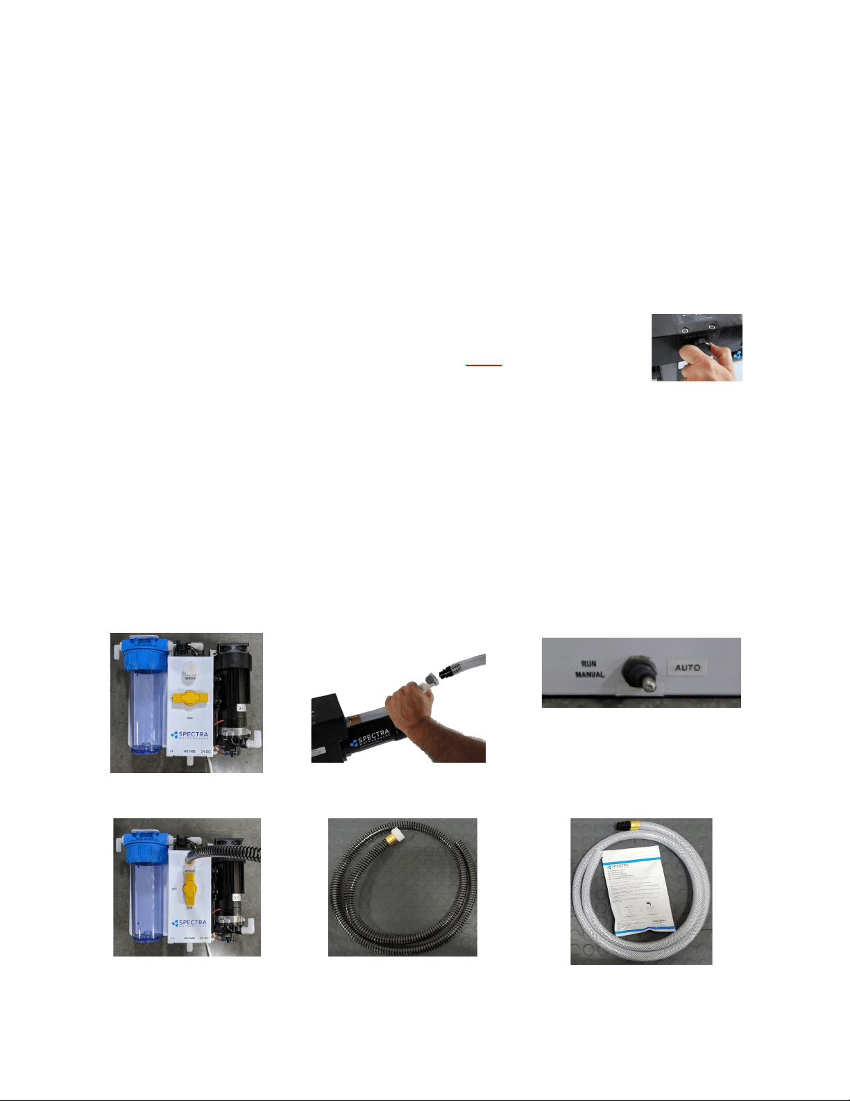
Adjusting Fresh Water Flush Duration
The Ventura Freshwater Flush Duration is set to a factory default of 3 minutes, which
is usually the right amount of time to ensure that sea water is thoroughly flushed out of
the watermaker using the least amount of fresh water. However, due to different
lengths of hose runs, different rates of flow, and different pressures in shipboard fresh
water systems, the flush duration can be optimized for your boat.
Set the Flush Duration with a small screwdriver so that the fresh water flush comes to
an end just as the salinity of the brine discharge drops below 1000 PPM, or no longer
tastes brackish. Since the flush duration can only be adjusted in round minutes, you
may want to lessen the duration to 2 minutes, to save water, or increase to 4 or more
minutes to ensure a thorough flush.
Also, the charcoal filter is rated for 1.5 GPM (6 LPM): If the system pushes more than
1.5 GPM through the charcoal filter (4.5 gallons in 3 minutes), a flow regulator can be
added.

33
General
Periodically inspect the entire system for leakage and chafing. Repair any leaks as
soon as you find them. Some crystal formation around the Clark Pump blocks is normal. Wipe
down any salt encrusted areas with a damp cloth.
Watermakers are at their best when run regularly. Biological fouling in the membrane is more
likely when a watermaker sits idle. A warm environment will cause more growth than a cold
environment. A fresh water flush every five days (30 days with the Z-Ion) will greatly reduce
biological growth, but may not stop it completely. The Z-Ion system protects the membrane
from bio-fouling without the use of storage chemicals.
The Seawater Strainer
The seawater strainer’s stainless steel element should be inspected, removed, and cleaned as
needed. Ensure that the thru-hull is closed before disassembly and the gasket is in place before
reassembly. When the system is put into storage, remove the strainer, rinse with fresh water,
and reassemble dry to impede corrosion. Check frequently during operation.
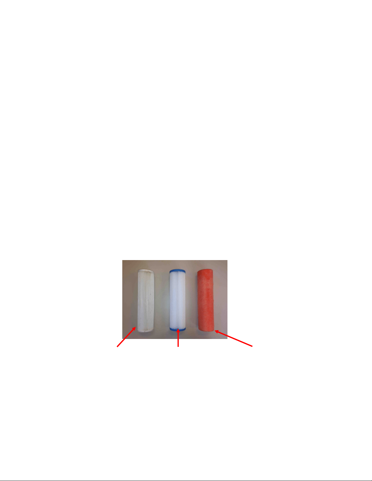
The Pre-filters
Prelter elements must be changed frequently. The rate is solely dependent on the input water.
A 5-micron lter might last you a 4-6 weeks in clear open ocean seawater, or be ruined in 45 in a
dirty harbor. A vessel may be sailing through seemingly super clear water, but cruise through a
plankton bloom and the prelter will be ruined. Filters may be cleaned up to three mes each
with a so brush and water in a bucket, hung overboard overnight, or dragged behind a vessel
underway. Drying in the sun helps remove odors. However, every me you clean o a prelter
element, sediment eventually gets forced deeper into the pleats of the prelter, making it
eventually not very eecve.
To service the lter close the thru-hull, open the prelter housing, remove the old lter, clean
out the housing bowl, and reassemble the housing with a new 5 micron lter element. Leave dry
unl next startup.
Use only Spectra-approved lters or you may void your warranty. Occasionally, lightly lubricate
the O-rings with silicone grease.
Oil/Water Separator (Optional)
To install oil water separator capability, add a second lter housing UPSTREAM of the 5 micron
housing. Service as you would per the instrucons above.
Maintenance

34
The Charcoal Fresh Water Flush Filter
Replace the charcoal filter element in the feed pump module at least every 6 months. This
filter protects the membrane by removing chlorine from the flush water. Use only a Spectra-
approved replacement.
The Feed Pump and Clark Pump
The feed pump and the Clark Pump require no routine maintenance except inspection for
leaks. Tighten any hose clamps or fittings that show signs of leakage. The high pressure fittings
threaded into the Clark Pump have O-ring seals with a straight thread. These should never leak
and should never be over-tightened. If one of the tube nuts starts to leak, it can be un-
threaded, sealed with a bit of silicone grease or oil, and tightened with two wrenches very
tightly.
The Membrane
Membranes are susceptible to mineral scaling, biofouling and oxidation damage. The leading
cause of fouling is biological growth that forms when the system is left unused without
flushing or pickling. Fouling from mineral scaling can happen under certain seawater
conditions, or from rust. Oxidation damage can occur if the membrane comes into contact
with any strong oxidant, such as Ozone, Chlorine, etc. Monitor the product salinity and feed
pressure for higher than normal readings, take environmental conditions into consideration.
Note that:
• Cold feed water or a higher salinity seawater source can cause high pressure.
• Low product flow is usually due to low voltage, a worn feed pump, or worn Clark Pump.
Due to the unique design of your Spectra system, low product water volume is typically not a
membrane problem, but frequently related to low voltage, a worn feed pump head, or a worn
Clark Pump. Always perform a flow test before cleaning your membrane.
Test to see if biological growth has occurred: Before running the system, remove the pre-
lter and examine its condion. If the lter housings are full of smelly, discolored water, the
system was not properly stored. Install a clean pre-lter.
Next check the membrane. Detach the brine discharge hose, aach the brine service hose, and
lead it to a bucket. Open the pressure relief valve 1/2 turn, and manually run the system for 30
seconds (metal toggle switch on feed pump module). Examine the brine water: If it is
discolored and smells bad, perform an SC-2 cleaning with unchlorinated water before running
the system pressurized. If the brine is fairly clean, follow the New System Startup procedure
on page 26 and run normally. Check for performance. Clean the membranes only if
performance is reduced.
See the Cleaning Procedure for complete instructions.
Maintenance - Cont.

35
Introducon to Spectra Chemicals
We use four types of chemicals: SC-1, SC-2, SC-3, and propylene glycol anfreeze. SC-1 and
propylene glycol are for system storage, while SC-2 and SC-3 are for membrane cleaning. Do
not use sodium-bisulfate, citric acid, or any other storage chemical not supplied by Spectra.
These chemicals, used to store other watermaker brands, will damage the Clark Pump,
membrane end plugs, manifolds, and other components. Using non-Spectra chemicals will
void the warranty.
***When system is unpickled, SC-1 should be purged for minimum 20 minutes. Propylene
Glycol should be purged for minimum 60 minutes***
Note: Never use any chemicals with the system pressurized! Always open the pressure relief
valve 1/2 turn. Always follow the instrucons for purging the chemicals as shown in the New
System Startup secon (page 26) of your owner’s manual.
Storage
SC-1 prevents biological growth when your system is idle. It should not be used as a cleaning
chemical, nor will it protect your system from freezing. A jar of SC-1 is mixed with 1 to 2
gallons of product or dechlorinated fresh water in a bucket and circulated through the system
for 10 minutes. This treatment will protect the system for six months, aer which the SC-1
treatment must be repeated. To use SC-1, follow the instrucons for Storage Procedure.
Spectra systems should be stored with propylene glycol if freezing is likely to occur. Propylene
glycol can be used instead of Spectra SC-1 storage chemical for storage in any climate, and
treatment is eecve for one year. Propylene glycol is a food-grade anfreeze used to
winterize RV’s, boats, and cabins. Do not use ethylene glycol automove anfreeze, which is
toxic and will damage the system.
The propylene glycol formulaons sold in marine and RV stores are usually diluted with water.
The water remaining in the watermaker before the storage procedure will further dilute the
anfreeze, reducing the microbial protecon and increasing the temperature at which the
mixture will freeze.
Anfreeze labeled “Minus Fiy” is a 25% soluon and will begin to form an icy slush at about
+15Degrees F (-10C) and will only provide burst protecon to about Zero F (-18C). Aer a
further 50% percent diluon by water remaining in the watermaker, “Minus Fiy” anfreeze
will only protect from bursng down to about +25F (-4C). Therefore if low temperature
freezing protecon is required a 60% or stronger anfreeze should be used. 60% soluons are
labeled “Minus 100” and will provide burst protecon to -15F (-27C) even aer a y percent
diluon with residual water. “Minus 200” formulaons are pure propylene glycol.
Maintenance - Cont.

36
Introducon to Spectra Chemicals - Cont.
Complete microbial protecon requires a 25% soluon of propylene glycol, so care must be
taken that the soluon remaining in the watermaker during long term storage is at least 25%,
even if freeze protecon is not required. For these reasons Spectra recommends that all
pickling be carried out with a 60% or greater concentraon.
See Winterizing with Propylene Glycol on Page 36.
Propylene glycol can be dicult to ush from a membrane, especially aer extended storage
periods. This results in high salinity water (high PPM) and residual avor in the product water.
We recommend ushing the system WITH THE PRESSURE RELIEF VALVE OPEN for 4-6 hours
aer storage with propylene glycol—the longer the beer. If, aer extended ushing, you sll
experience low product water quality, cleaning with SC-2 usually removes all traces of
propylene glycol and returns the salinity to the level it was before storage with propylene
glycol. See the Membrane Cleaning Procedure.
Cleaners
Avoid unnecessary cleaning, and avoid cleaning as a diagnosc tool.
SC-2 is an alkaline cleaner used to remove light oil, grime and biological growth. It is most
eecve if heated to 120 deg. F (49 deg. C). In most cases the water quality will increase in
PPM (salinity) aer an SC-2 cleaning. Aer a few hours it should recover to near the level it
produced before the cleaning.
SC-3 is an acid cleaner used to remove mineral and scale deposits. In most cases this is used
rst and if there is no improvement, go on to the SC-2 cleaning. SC-3 will in most cases lower
the product PPM and overall pressures. Scaling is a slow process that may take several months
or years.
For cleaning with either SC-2 or SC-3, see Membrane Cleaning Procedure.
Maintenance - Cont.
37
NOTE: The Ventura contains about 2 gallons of water at any given me, so with 2 gallons in the bucket there will
be a total of 4 gallons of soluon.
1. Close the saltwater intake seacock.
2. Push the Freshwater Flush buon to perform a ush. Repeat a second ush.
3. Disconnect the brine discharge hose from the Clark Pump at quick disconnect. Replace with the
vinyl brine service hose* from your service kit. Lead the service hose into a 5 gallon bucket.
4. Push Freshwater Flush again and stop the feed pump when the bucket has lled with one gallon of
non-chlorinated freshwater (or ll a bucket with a gallon of dislled).
5. Mix one 8 oz. container of SC-1 storage compound with the water in the bucket. It will not dissolve
completely, which is normal, and any undissolved parcles will be caught by the pre-lter.
6. Connect black spiraled reinforced service hose** to the service port (garden hose style ng)
above the yellow valve on the feed pump module and lead the hose into the
soluon in the bucket, creang a closed loop. Turn the yellow service valve to
SERVICE.
7.
Ensure the pressure relief valve on the Clark pump is OPEN (unpressurized), 1/2
turn counterclockwise OR THE MEMBRANE WILL BE DAMAGED.
8. Turn on the feed pump using manual toggle switch***. The system will draw soluon from the
bucket and return it via the brine discharge hose. Circulate the storage soluon through the system
for 20 minutes. Turn o the feed pump when nished.
Clean Up:
1. Remove the brine service hose from the Clark Pump brine discharge using quick disconnect, and
replace with the original hose that leads to the discharge thru-hull.
2. Pump the bucket dry using the manual toggle switch, turn o when empty.
3. Turn the yellow service valve back to RUN. Remove the intake service hose, and replace the cap.
4. Close the seacock, drain then clean the sea strainer and pre-lters. Reassemble dry with new
lters. Leave the pressure relief valve open, since the next me you run the system you will need
to purge the storage chemicals with the system unpressurized.
Your system is now protected from biological growth for 6 months.
Ventura Remote Manual Storage Procedure
**Intake service hose con-
nected and yellow service
valve handle to SERVICE
*Connecng brine discharge
service hose at quick disconnect
Service valve OFF, in FLUSH
posion
***Manual toggle switch
**Black spiraled
reinforced intake
service hose
*Vinyl Brine Discharge Service
Hose
For further illustration, see Figure 2 on page 38.
38
See descripon of propylene glycol formulaons, and ushing from system, on page 33-34.
1. Close the saltwater intake seacock.
2. Push the Freshwater Flush buon to perform a ush. Repeat a second ush.
3. Disconnect the brine discharge hose from the Clark Pump at quick disconnect. Replace with the vinyl brine
discharge service hose* from your service kit. Lead hose into a 5 gallon bucket.
4. Push Freshwater Flush and stop with one gallon of freshwater in the bucket (or use dislled).
5. There are two gallons of water in the watermaker, so add potable water anfreeze to the bucket per the
label instrucons based on the protecon level needed.
6. Connect black spiraled intake reinforced service hose** to the service port (garden hose style ng) above
the yellow valve on the feed pump module and lead the hose into the soluon in the
bucket, creang a closed loop. Turn the yellow service valve handle to SERVICE.
7. Ensure the pressure relief valve on the Clark Pump is OPEN 1/2 turn (unpressurized).
8. If a stronger concentraon of anfreeze is required you can discard the rst one or two
gallons of water from the discharge line before placing it into the bucket to recirculate. Add
more propylene glycol to the intake bucket if necessary. Turn on the feed pump using the
manual toggle switch*** and the pump will draw propylene glycol from the bucket, and the brine discharge
service hose will return it, creang a closed loop. Run the feed pump and circulate the anfreeze for
approximately 20 minutes. Stop the feed pump by moving the toggle switch back to ‘RUN AUTO’.
Clean Up:
1. Remove the brine discharge service hose from the Clark Pump, and replace with the original brine discharge
hose that leads to the thru-hull. You may now pump the bucket dry by engaging the toggle switch again. Stop
when the bucket is empty, switching back to ‘RUN AUTO’.
2. Turn the yellow service valve handle to OFF. Disconnect the intake service hose and replace cap.
3. Drain the seawater strainer and the hose leading to the feed pump module. Disconnect the product tubing
from the membrane housing and blow residual water out of the tubing. Empty the charcoal lter housing
and ush water lines.
Your system is now protected from biological growth and freezing for 12 months.
Winterizing with Propylene Glycol
**Intake service hose connect-
ed and yellow service valve han-
dle to SERVICE
*Connecng brine discharge
service hose at quick disconnect
Service valve OFF, in FLUSH
posion
***Manual toggle switch
**Black spiraled
reinforced intake service
hose
*Vinyl Brine Discharge
Service Hose
For further illustration, see Figure 2 on page 40.
39
Spectra cleaning compound (SC-2 or SC-3) must be mixed with freshwater at a rao of 1 container of compound to 3 gallons (12L) of non-
chlorinated water. An average of two gallons (8L) of water is already present inside a Ventura system, so this water must be gured into the
mixture. A Ventura system requires one container of compound per cleaning.
1. Turn the yellow service valve on the feed pump module to OFF (horizontal, see photo*).
2. Push Freshwater Flush to ush the system. Repeat, to ush the system twice.
3. Remove the cap on the service port on the feed pump module and install the black spiraled reinforced
intake service hose** from the service kit. Remove the quick disconnect ng from the brine discharge
outlet of the Clark Pump, and replace it with the vinyl brine discharge service hose***. Lead both hoses
into a 5 gallon (20 liter) bucket.
4. Push the Freshwater Flush buon and run the feed pump unl one gallon of fresh water runs into the
bucket from the brine discharge service hose (or ll with a gallon of dislled water). Stop the system.
5. Turn the yellow service valve to the SERVICE posion.
6. Make sure that the pressure relief valve on the Clark Pump is open (unpressurized).
7. Mix the SC-2 or SC-3 cleaning chemical in the bucket with the freshwater. If possible (for maximum
eecveness), heat the soluon to approximately 120 deg. F (49 deg. C).
8. Start the system using the manual toggle switch**** on the control box. The intake service hose will
draw soluon from the bucket and the brine discharge service hose will return it. Circulate the soluon
through the system in this manner for 45 minutes.
9. Stop the pump. Replace the brine discharge overboard hose and run the pump unl the bucket is
empty. Stop the pump and turn the yellow service valve back to the RUN posion. Restart the pump
and run for 20 minutes to ush the chemicals out of the system
(DO NOT CLOSE the pressure relief
valve!)
10. Move the manual toggle switch on the Control Box to RUN AUTO.
The system may now be restarted, ushed, or stored.
Membrane Cleaning Procedures
**Intake service hose con-
nected and yellow service
valve handle to SERVICE
***Connecng brine discharge
service hose at quick disconnect
*Service valve OFF, in FLUSH
posion
****Manual toggle
switch
**Black spiraled
reinforced intake
service hose
***Vinyl Brine Discharge
Service Hose
For further illustration, see Figure 2 on page 40.
40
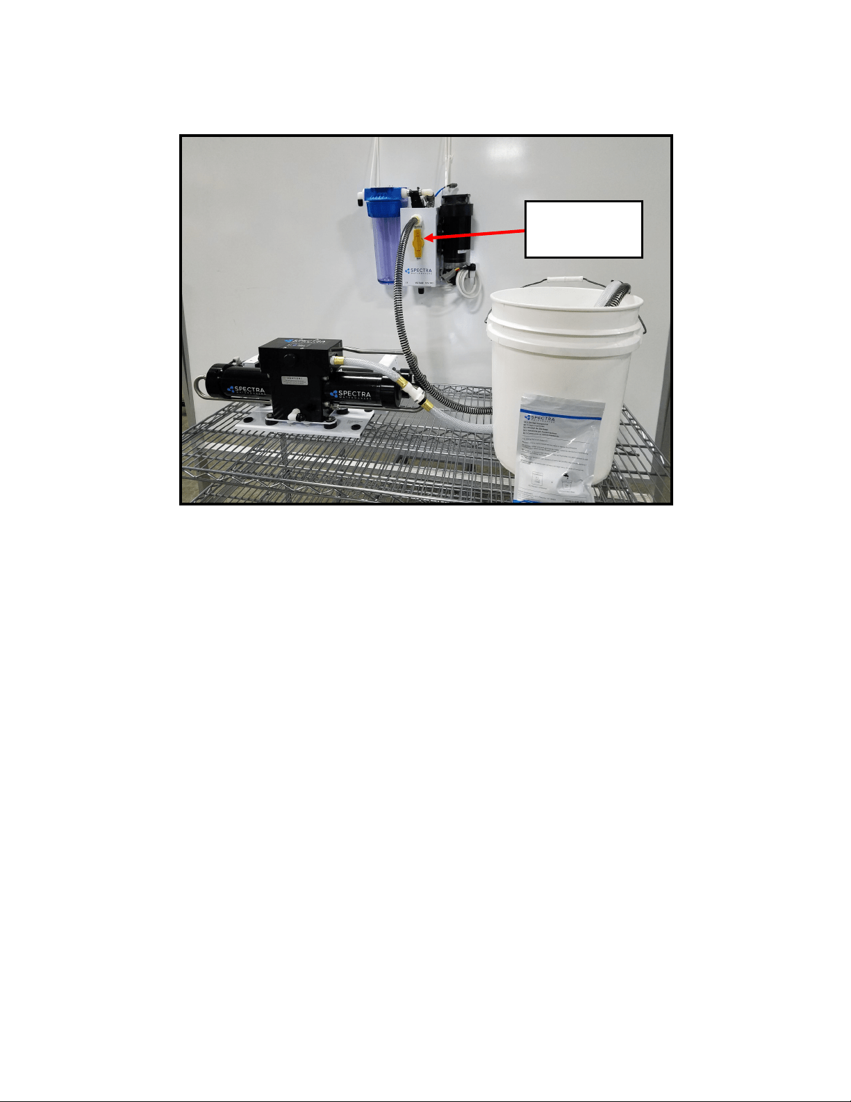
Service Mode - Example
Figure 2
Illustrates hose connections and subassemblies for winterizing, storage procedures, and membrane cleaning.
3-Way Valve
pointed up toward
“Service”

41
Suggested Spares for Ventura Connect
Short term cruising, weekends etc.
A basic cruise kit B. This kit consists of three 5 micron lters, three 20 micron lters, and SC-
1 storage chemical.
Cruising 2 to 6 months at a me.
Two basic cruise kits, one replacement charcoal lter, and one replacement feed pump
head.
Longer than 6 months
Addional lters, oshore cruising kit consisng of Clark Pump seals, O-rings, tools and
membrane cleaning chemicals. One replacement strainer screen, replacement O-ring for
strainer screen, and replacement O-rings for the lter housings. Spare feed pump or feed
pump diaphragm.
Common Parts:
Item Part Number
SC-1 STORAGE CHEMICAL KIT-CHEM-SC1
SC-2 CLEANER KIT-CHEM-SC2
SC-3 CLEANER KIT-CHEM-SC3
BASIC CRUISE B KIT-BCK-B
OFFSHORE REBUILD KIT KIT-OFFSH
5 MICRON FILTER FT-FTC-5
20 MICRON FILTER FT-FTC-20
CHARCOAL FILTER FT-FTC-CC
5” STRAINER SCREEN FT-STN-5S
OIL/WATER FILTER FT-FTC-OW
FEED PUMP EL-FP-12V or 24V
FEED PUMP HEAD PL-PMP-SFPH
FEED PUMP DIAPHRAGM EL-FP-DP
5” STRAINER O-RING SO-STN-5SS
FILTER HOUSING O-RING SO-FHS-10H
SALINITY PROBE EL-MPC-SP4
CHARCOAL FILTER HOUSING O-RING SO-FHS-3PCS10

42
Pump runs intermiently,
cycling on/o
• Overpressure switch on ShurFlo
pump opening
• Adjust or replace switch (see
page 58)
Feed pump runs constantly,
will not turn o
• Turn o manual switch on control box
• Manual switch in ON
posion on control box
Display acvates, but pump
will not run
• Loose or broken pump wire
connecon
• Tanks are full (if equipped
with tank switch). If full, Run
& Stop LED should be lit.
• Check wiring at terminal block
inside control box
• Check tanks– system cannot be
started if tanks are full.
System runs, no product water
delivered to water tanks
• Disconnected or broken prod-
uct tubing
• 3-Way Valve Incorrectly set
• Check product tubing
• Check 3-Way Valve posion
Feed pump runs with loud
noise
• Intake blocked
• Air in system
• Check thru-hull valve
• Check sea strainer for leaks
• Check fresh water ush module
for leaks
• Re-prime system (restart)
Troubleshooting Ventura Remote Manual Systems
SYMPTOMS
PROBABLE CAUSE
REMEDY
High feed pressure, High Am-
perage, & Product Flow down
up to 15%
• Colder or more saline water
• Brine or product ow path
subject to back pressure
• Scaled or fouled membrane
• Normal condion
• Conrm by roung into a bucket to test
• Clean Membrane
Feed Pump not running, no
noise
• No power at feed
pump
• Pressure switch Failed
• Check voltage at pump
• Adjust or bypass. To
bypass, jump terminals
on switch with electri-
cal wire. Only bypass
to test, not run long
term.
Feed pump turns on, no pres-
sure
• Feed pump air locked
• Pressure relief valve open
• Open pressure relief valve
to bleed the air, then close
to start
• Close pressure relief valve
Low Feed Pressure, Low Am-
perage
• Warm saltwater or brackish
water
• Normal condion
No product ow, good brine
discharge ow,
Recovery percentage is 0 (See
Flow Test)
• Internal leak in Clark Pump
• While system is running, kink brine
hose to stop ow unl pressure rises
to 125psi, release hose quickly, repeat
no more than 10 mes in succession
• Inspect Clark Pump Check Valves
• Complete Service is recommended.
Contact Dealer or see Clark Pump re-
build manual. Install Oshore Kit

43
SYMPTOMS PROBABLE CAUSE REMEDY
Low product ow. Recovery
percentage below minimum
nominal value (See Flow Test)
• Pressure relief Valve open
parally
• Internal leak in Clark Pump
• Close Pressure relief valve
• Complete service recommended. Contact
dealer of see Clark Pump rebuild manual.
• Install oshore kit
Troubleshooting Ventura Remote Manual Systems
Low product ow, more than
1 GPH Total ow down (see
ow test)
• Motor receiving less than
12.5 VDC
• Blockage or restricon in
system
• Thru-hull blockage
• Mineral Scaling
• Pump or Motor worn
• Check wiring for voltage drop. Increase
wire size if necessary
• Check power supply
• If available, turn on baery chargers
• Replace prelter, service strainer, check
all hose runs
• Conrm by using intake service hose and
bucket of seawater to bypass.
• Clean Thru-hull
• Perform SC-3 Cleaning (Note: By design, it is
rare for a membrane to cause low total ow on
Spectra systems)
• Pump should be able to reach 125psi
within 3 seconds, & push 1.6 G/M
• Replace pump head
Asymmetrical pressure and ow
readings between pump shis,
more than a few psi
• Scored Clark Pump annular
rings and/or reversing valve
spool
• Scored Clark Pump piston rod
and/or lip seals
• Scored Clark Pump cylinders
• Replace
• Conrm by opening test port on back
of Clark Pump. If constant ow,
replace seals and circular sand rod
(240 grit) or replace piston rod
• Hone, circular sand (240 grit) or
replace

44
SYMPTOMS PROBABLE CAUSE REMEDY
Troubleshooting Ventura Remote Manual Systems
PPM High
• TDS meter needs calibraon
• Feed Flow or Clark Pump
Problem
• Membrane fouled or dam-
aged
• Fouled Prelters
• Recalibrate TDS meter or taste test water
unl it can be replaced
• Low product ow, recovery percentage, or
feed pressure can lead to drop in product
water quality. Perform Flow Test &
address ow issue.
• Clean membrane or consult dealer about
membrane damage.
If system ow (product plus brine) is to
specicaon, the membrane is clean, the
product ows are consistent with the
system ow, and the water quality is sll
not acceptable, then replacement of the
membrane is indicated. By design, high
ppm typically has to do with something
other than the membrane itself.
• Freshwater ush procedure needs to be
tested and adjusted. PPM of brine
discharge must be below 1000ppm at end
of ush cycle.
• Replace lters or run watermaker for an
extended period of me with pressure
relief valve open to rinse.

45
The ow test is the most useful diagnosc test for system performance, and should be done
before replacing or cleaning your membrane. Changes in producon or water quality are
normally caused by something other than the membrane, unless the system has been le
unused for a long period of me.
Before the ow test, change all lters and clean the sea strainer. Carefully check for water or
air leaks, as air in the system will cause low producon and errac salinity. Look for air bubbles
in the product ow meter, feed water hoses, and brine overboard hose.
Run the system and watch the feed pressure very closely. If the feed pressure to the Clark
Pump is asymmetrical from one stroke to another, this could be part of the problem. A
dierence of a few PSI is acceptable, but anything over that is an issue. If the pump is
asymmetrical, Clark Pump repairs should be done before connuing with these tests.
If no asymmetry is noted, connue with this test.
Make sure the ShurFlo overpressure cutout switch (PL-PMP-SFPH) is set to 125 PSI. With the
pump running, close the brine discharge thru-hull or kink the brine discharge hose. The feed
pressure should rise to 125 PSI, then the pump should shut o. If the pump shuts o at a
lower pressure see Adjust ShurFlo Pressure Switch on page 51.
You will need a graduated bucket, either a graduated pitcher or large measuring cup, and a
stopwatch. Before the flow test, change all filters and clean the sea strainer. Log the voltage at
the feed pump at the same time. Confirm at least 12.5 Volts at the feed pump on 12-Volt DC
systems; 25 volts on 24-Volt DC systems.
Take two measurements and compare them with the table on the following page. The first
measurement is the product flow alone. The second is the product flow combined with the
brine discharge flow to get the total flow or feed flow. You may take these measurements by
two methods:
1. Time the product flow into a graduated pitcher, then divert both the product flow and
brine discharge together into a bucket to measure total flow.
OR
2. Divert the product flow into the pitcher while diverting the brine discharge into the bucket.
Time the flow of both. After calculating the product flow, pour the pitcher of product into the
bucket of brine to measure total flow.
The ratio of product flow to total flow gives us our recovery rate, as a percentage. If the
percentage is below the minimum it indicates an internal leak in the Clark Pump.
Ventura Flow Test

46
1. Product Flow: Product flow is expressed in Gallons Per Hour (GPH) or Liters Per Hour (LPH), by
this equation:
3600 ÷ time in seconds x quantity of water in gallons or liters=GPH or LPH
There are 3600 seconds in an hour.
Example: It took 3 minutes and 35 seconds to collect 1 gallon of product water.
3600 ÷ 215 x 1 = 16.74 GPH (3 minutes, 35 seconds is 215 seconds)
Example: It took 2 minutes and 25 seconds to collect 2.5 liters of product water.
3600 ÷ 145 x 2.5 = 62.07 LPH (2 minutes, 25 seconds is 145 seconds)
2. Total Flow or Feed Flow: Feed flow or total flow (brine + product) is expressed in Gallons Per
Minute (GPM) or Liters Per Minute (LPM) , by this equation:
60 ÷ time in seconds x quantity of water in gallons or liters = GPM or LPM
Example: It took 1 minute and thirty-seven seconds to collect 5 gallons of total flow.
60 ÷ 97 x 5 = 3.09 GPM (1 minute, 37 seconds is 97 seconds)
Example: It took 53 seconds to collect 12 liters of total flow.
60 ÷ 53 x 12 = 13.58 LPM
3. Recovery Rate: Product Flow ÷ Total Flow = Recovery Rate %
Example: 6.5 GPH product flow = .063 or 6.3%
1.7 GPM total flow x 60
(you must first multiply total flow by 60 to convert from GPM to GPH)
*pressure relief valve open ½ turn
In order to make good quality product water, you need the proper amount of feed water ow, as in
the table above. Compare the product ow to the total feed ow. Product ow should be 6.5%
minimum 5.5%) of total ow for a Ventura 150, and 9% (minimum 8%) of total ow for a Ventura
200T. If product percentage is low, you may have an internal leak in the Clark Pump.
For every
1
/
10
th
of a GPM feed water ow loss, we will lose about
1
/
2
gallon per hour of product ow
and the salinity will go up 100 PPM.
Low feed ow combined with low system pressures is most frequently caused by a worn Shuro
pump head (PL-PMP-SFPH).
System
Feed Static * Feed Flow Product Flow
Pres-
sure
Pres-
sure Flow
MIN MIN Flow Flow MIN MIN
psi bar
psi gpm lpm gpm lpm gph lph gph lph
Ventura 60-70 4.2-5
10-15 1.7 6.4 1.65 6.2 6.5 24.6 5.7 21.5
VT 200 80-90
5.6-
6.3
20-25 1.7 6.4 1.6 6.0 8.3 31.4 7.7 29.1
Ventura Flow Test - Cont.

47
Nominal Operating Parameters
Parameter Minimum Maximum
Product Quanty 5.7 GPH (21.5 LPH)/Ventura 150
7.7 GPH (29.1 LPH)/Ventura200
6.5 GPH (24.6 LPH)/Ventura 150
8.3 GPH (31.4 LPH)/Ventura 200
Product Quality <300 ppm 750 ppm
Feed Pressure N/A 70 psi (5 bar)/Ventura 150
90 psi (6.3 bar)/Ventura 200
Amp Draw Ventura 150 9.0A @ 14VDC; 4.5A @ 26VDC
Amp Draw Ventura 200 10.0A @ 14VDC; 5A @ 26VDC
Total Flow (Brine + Product) 1.65 GPM (6.2 LPM)

48
With any product water quality issue, you must ensure accurate calibraon if you are using a
salinity meter. For general quality evaluaon, your taste is always good enough.
Using membranes for water desalinaon through reverse osmosis is not an exact science and
two idencal systems can have dierent product quality. World health standards deem
water of up to 1000 PPM of total dissolved solids acceptable for drinking. We consider any
thing below 750 PPM acceptable but not ideal, and anything below 500 PPM excellent.
Factors that could aect water quality are addressed below.
LOW SYSTEM FLOW OR PRESSURE will equate to lower product quality (higher PPM).
Ventura systems, which have a higher feed to output pressure rao (See nominal
pressures under Flow Test, page 28), as well as a higher feed ow/membrane area
rao, will produce water in the 150-200 PPM range.
DAMAGE TO THE MEMBRANE by chlorine contaminaon. Flushing the system with
chlorinated water will irreparably damage the membrane. Charcoal lters are used to
absorb any chlorine which might be present in ush water. They must be of proper
specicaon to be suitable. See page 49. There is no test for chlorine damage except
the process of eliminaon of other causes.
DIRTY OR SCALED membranes. A dirty (foreign material), scaled (mineral deposits), or
contaminated (bacterial growth) membrane can result in poor water quality and
abnormal operang pressures. If operang pressures are above normal, then cleaning
is indicated. If the system pressures are within operang normal range, cleaning may
have lile result. Avoid cleaning as a diagnosc tool. Low water quality aer storage
with propylene glycol can usually be remedied by extended ushing or an SC-2
cleaning. (See pages 44-45 and 48.)
MECHANICAL LEAKAGE within the membrane pressure vessel. This is an unlikely but
possible cause of poor water quality. A pinched or damaged O-ring within the
pressure vessel, a scratch on the product tube on the membrane, a scratch within
one of the end caps, or a seal fouled by contaminaon could allow sea water into the
product water.
If system ow (product plus brine) is 1.5 GPM or above, the membrane is clean, the product
ows are consistent with the system ow and the water quality is sll not acceptable, then
replacement of the membrane is indicated.
Poor Product Water Quality
49
The following pages include Spectra’s most commonly used technical bullens, covering tests,
adjustments, troubleshoong, and common points of confusion. Many more technical
bullens are available on the Spectra website, www.spectrawatermakers.com.
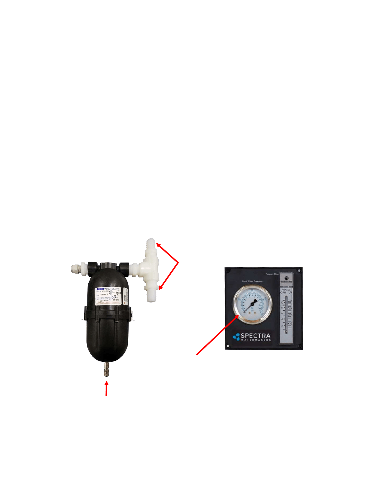
ACCUMULATOR PRESSURE
Your Spectra watermaker is supplied with a pressure accumulator tank (PL-ACC-TK), which
should be installed in the feed water line between the 5 micron Pre-lter and the Clark Pump.
The purpose of the feed line accumulator is to reduce the spikes in the feed pressure caused
by the cycling of the Clark Pump. If the accumulator is not properly charged it can lead to
problems with the Shuro Pump pressure cutout switch (see page 58). The accumulator has a
Schrader air valve, like a car re, which allows the internal air bladder of the accumulator to
be pre-charged. The accumulator should be pumped up to about 65 psi (4.5 bar) for best
results. Add air using a re pump or air compressor. You can experiment with the exact
pressure that will give the best pulsaon dampening on your installaon.
Schrader valve
Connecons to feed
water hose, between
Shuro pump and
Clark Pump
Analogue feed pressure
gauge
Technical Bulletins
50
During normal operaon, the feed water is ltered in two stages. First it passes through a ne
mesh metal sea strainer, which protects the feed pump from foreign materials and sea
creatures. Aer passing through the feed pump, the feed water passes the lter housings
containing 20 and 5 micron elements, removing very ne parcles that could damage the
Clark Pump and shorten membrane life. An addional carbon lter prevents the entrance of
chlorine during fresh water ushing (see next page).
Pre-lter maintenance schedules will vary widely depending on how and where the system is
used. If large amounts of feed water are run through the system over a relavely short period
of me in biologically ferle near-shore waters, the prelters will plug up, water producon
and quality will drop, and the system pressure will change dramacally. In blue water
condions the pre-lters may only need to be changed every week or two.
When operated for only an hour or two a day in inland or near-shore waters, the trapped
plankton will begin to decay in the lters long before the elements plug up. The decaying
plankton and bacteria will cause a roen egg smell in the product water. This decay will set in
overnight in tropical waters, or aer a week or two in higher latudes. If handled gently and
changed regularly before they get too smelly, lters can be cleaned several mes. (See
Maintenance, page 33.)
Our lter element part numbers are FT-FTC-XX, where the last digits indicate the micron
rang. FT-FTC-5 is for a 5 micron element, FT-FTC-20 is a 20 micron element. The oponal oil/
water separator is FT-FTC-OW.
5 Micron
20 Micron Oponal Oil/Water Separator
PREFILTERS

51
The charcoal lter element (FT-FTC-CC) removes chlorine from the fresh water ush water
supply, as the RO membrane can only handle small amounts of chlorine without permanent
damage.
The charcoal lter used for the fresh water ush system will not plug up unless you have very
dirty domesc water in your boat’s supply tank.
The charcoal lter we supply removes 99.7% of the chlorine. Beware when buying other
charcoal lters. If they don’t specify the percentage of chlorine removed, don’t use them.
Cheap ones may remove only 60% or 70%. Also, there are aermarket lters which are very
close to, but not exactly, the right dimensions, and they will not seal in the housing. If you
skimp on the charcoal lter you risk damaging a $600.00 membrane on the rst ush. The
other factor is the ow rate that the lter can handle. Because the chlorine is adsorbed by the
charcoal, it must remain in contact with the charcoal for a sucient period of me for the all
of the chlorine molecules to be captured. The lters we use can handle 1.5 gallons (6 liters)
per minute ow, and are good for 3000 gallons (12,000 liters) at 1.5 GPM, or six months,
whichever comes rst. Regardless of the amount of water treated, the charcoal loses its
eecveness aer six months.
Charcoal lter, Spectra part number FT-FTC-CC
CHARCOAL FILTERS

52
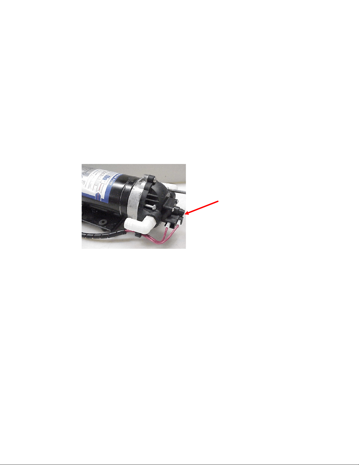
If the pump has power to it but the pump won’t run, rst check the pressure switch. The
pressure switch (EL-FP-PS) is located on the wet end of the pump and has two red wires
plugged into it (see photo, next page). Jump the two red wires together and see if the pump
runs. You can safely run the system with the pressure switch jumped, just keep an eye on the
feed pressure and don’t let system pressure exceed 110 PSI. Replace the switch when a spare
is available. The pressure switch should never open unless there is a problem with the system
or it is incorrectly adjusted. See Adjust Shuro Pressure Switch on next page.
If the pump will not run with the pressure switch jumped then it is most likely a problem with
the brushes or overheat protecon switch inside the motor. The motor will come completely
apart by removing the two screws on the end of the motor. Remove the rear cover and paper
insulator. Pull out the plasc brush holder. The thermal switch is located on one of the brush
leads. With an ohmmeter, check for connuity through the switch. If it is open, you can make
temporary repairs by wiring around it, being careful that your new wiring doesn’t chafe on the
moving parts, nor resist the springs that push the brushes on to the commutator. The overheat
switch is unlikely to fail unless the motor has overheated. Consider relocang the pump or
improving venlaon if the overheat protecon has failed.
If any corrosion is apparent the brushes may be scking. Once apart clean all the carbon dust
from all the parts. Clean the commutator with light sandpaper. Make sure to clean the small
grooves on the commutator with a small sharp tool to remove the carbon in between the
segments. Adjust the springs on the brush holders so the brushes slide smoothly in and out. If
the bearings are rough and binding, remove the rubber dust cover to clean them, grease them,
and work them free by hand. Don't service the bearing unless absolutely necessary.
Reassemble in reverse order. You can hold the carbon brushes back with papers clips inserted
through the slots in the brush holder so they don't hang up on the bearing during assembly.
Make sure the corrugated bearing shim doesn't push out. If it does, push it back into place.
SHURFLO PUMP WON’T RUN
53
Shuro feed pumps are equipped with a high pressure cutout switch (EL-FP-PS). This is the
small black unit on the end of the wet end of the pump head (PL-PMP-SFPH) where the two
red wires connect. If the pressure switch is not properly adjusted the pump may cut out each
me the Clark pump cycles and the feed pressure spikes. When this happens the producon
will drop and salinity will increase. The points in the switch will fail quickly if set too low
because of the constant arcing each me the Clark Pump shis.
On the very center of the switch is a small 5/64” Allen screw. While running the system close
the brine discharge seacock or kink the discharge hose, to block the ow. Watch the pressure
gauge and adjust the pressure switch to shut o at 125 psi. Turn the Allen screw clockwise to
increase the cut o set point.
Pressure Switch
Adjusng Screw
ADJUST SHURFLO PRESSURE SWITCH

54
Insert .pdf here after
conversion to .pdf.

55
Electrical Specifications
Operang voltage limits: 10—14.6VDC
Outputs: 5VDC:– 2000mA Total for all outputs.
VLV 1&2: 1 Amp DC priming valve solenoid.
AUX 1-3: 1 Amp DC auxiliary output.
Never connect anything to the Spectra Connect without factory approval. Serious damage
can occur!

56
Exploded Views & Part Numbers

57
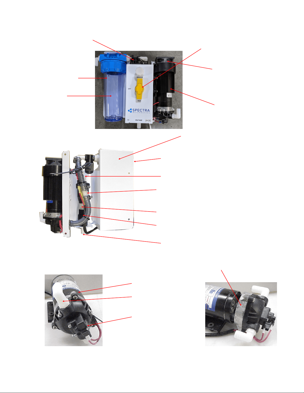
58
Part Numbers
Fig 2 Fig 3
3/4” 3-Way Valve
PL-VLV-3W3/4
Cooling Fan 12V, 24V
KIT-FK-12,24
Feed Pump Heat Sink
EL-FP-FPHS
Ventura Feed Pump Bracket
FM-VT-ITM
Feed Pump 12V, 24V
EL-FP-12V, 24V
3/8”NPT X 5/8” Hose Barb El.
PL-HBE-3/8X5/8
Pump Head Assembly W/Press. Switch
PL-PMP-SFPH
Feed Pump Pressure Switch
KIT-FP-SFSK
1-Way Solenoid Valve 12V, 24V
PL-SLN-1/4O12SV, O24
3/4MPTx5/8 HOSE BARB EL
PL-HBE-3/4X5/8
3/4 NYLON STREET EL
PL-MFF-1/2X1/2
3/4MPTX 5/8 HOSE BARB TEE
PL-TEE-3/4M5/8B
NIPPLE
PL-NP-3/4X2
CHECK VALVE
PL-CKV-3/4F-F
3/4MPT X 5/8 HOSE BARB
PL-HBS-3/4X5/8
FILTER HOUSING
FT-FTH-10L3PCS
CHARCOAL FILTER
CARTRIDGE
FT-FTC-CC
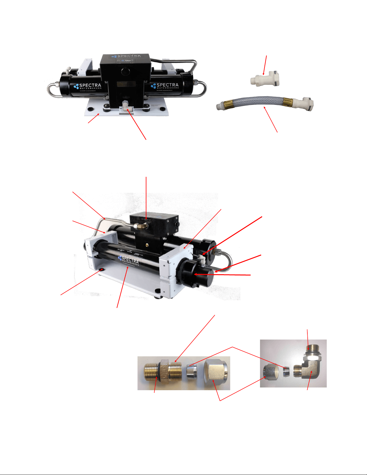
59
Plate Bracket
FM-PVB-PB
Rubber Mount
HD-RBP-RM
Plastic Spacer
HD-SPN-MKINS
Plate Bracket End
FM-PVB-PBE
Pressure Vessel End Cap
FT-PV-EP1
Pressure Vessel End Ring
FT-PV-ER
Nickel-Bronze High Pressure Elbow
PL-MTE-3/4S1/2B
Nickel-Bronze High Pres-
sure Straight Fitting
SUB-MTS-3/8X1/2
Pump to Pressure Vessel
Upper SS Tube:
PL-TB-HP-HPTVUS
Pump to Pressure Vessel
Lower SS Tube:
PL-TB-HP-HPTPVLS
(not pictured)
Stainless Fitting Hex Nut
PL-HWR-1/2HN
1/2” Stainless Ferrule
PL-HWR-1/2FR
Connector O-RING
SO-HPP-CT
3/4”-16 Straight Thread
O-RING
SO-FT-STF
Nickel-bronze high pres-
sure 90 degree fitting
PL-MTE-3/4S1/2B
3/8”NPT Quick Disc.
Coupling Body
PL-QDC-BD3/8
3/8”NPT X 5/8” Hose Barb El.
PL-HBE-3/8X5/8
20-Inch Hi Rejection Membrane
FT-MB-20F
INLET HOSE ASSEM.
SUB-CT-Z-HPILHA
PRODUCT OUTLET FIT-
TING
PL-FTE-1/8X1/4P
Part Numbers - Cont.
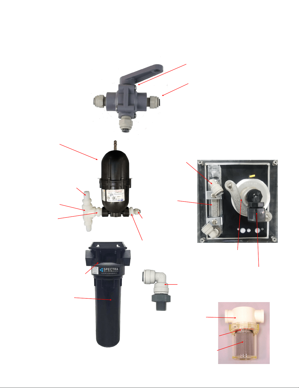
60
1/8MPT X 1/4 TUBE EL
PL-MTE-1/8X1/4J
PRODUCT FLOW METER
PL-FMT-10
Part Numbers - Cont.
1/8”NPTX1/4” Tube
fitting Elbow
PL-SWF-1/8X1/4J
PREFILTER HOUSING
FT-FTH-10H
5 MICRON FILTER
CARTRIDGE
FT-FTC-5
PRODUCT WATER SAMPLING
VALVE
PL-VLV-3W1/4
1/4 TUBE X 1/4 MPT STRAIGHT
FITTING
PL-MTS-1/4X1/4P
or
PL- MTE-1/4X1/4P
ELBOW FITTING 1/4 TUBE X 1/4
MPT EL (not shown)
Wall Mounting Clamps (not shown):
(2)PL-CLP-3/4CAR 3/4" CAR-
LON CLAMP
PRESSURE GUAGE
PL-PSG-LP2.5
ACCUMULATOR
PL-ACC-TK
1/2MPT X 5/8 HOSE
BARB PL-HBS-
1/2X5/8
1/2” TEE
PL-TEE-1/2FN
1/2” NIPPLE
PL-NP-1/2N
1/4MPT X 1/4 TUBE
STRAIGHT FITTING
PL-MTE-1/4X1/4
1/2 X 1/4 BUSHING
PL-BSH-1/2X1/4N
SEA STRAINER
FT-STN-5
5” STRAINER O-RING
SO-STN-5S
STRAINER SCREEN
FT-STN-5S
1/4FPT X 1/4 TUBE
EL
PL-FTE-1/4X1/4P
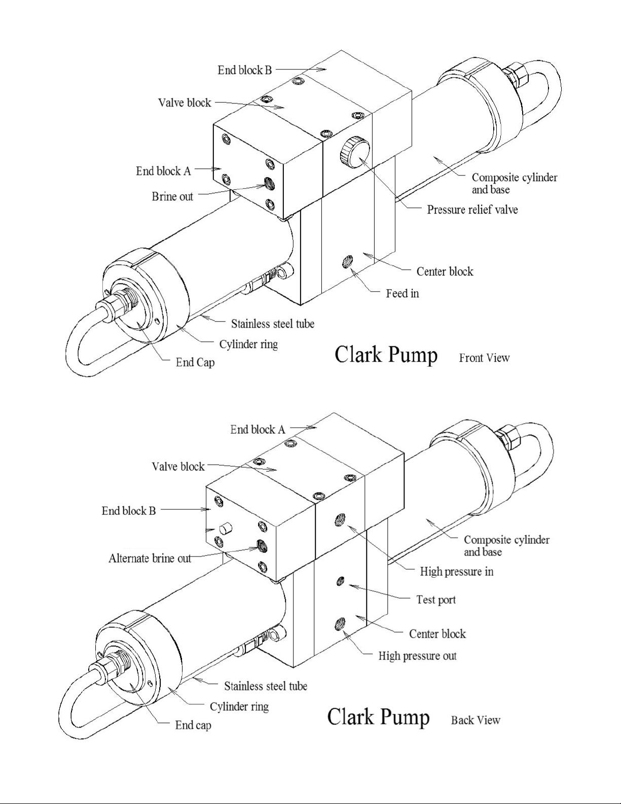
61
HP-TB-VEB-B
HP-TB-VB
HP-TB-VEB-A
HP-TB-BV
HP-CB-CB7
HP-CYL-SST
HP-CYL-R
HP-CYL-EC
HP-CYL-CCA
Not used
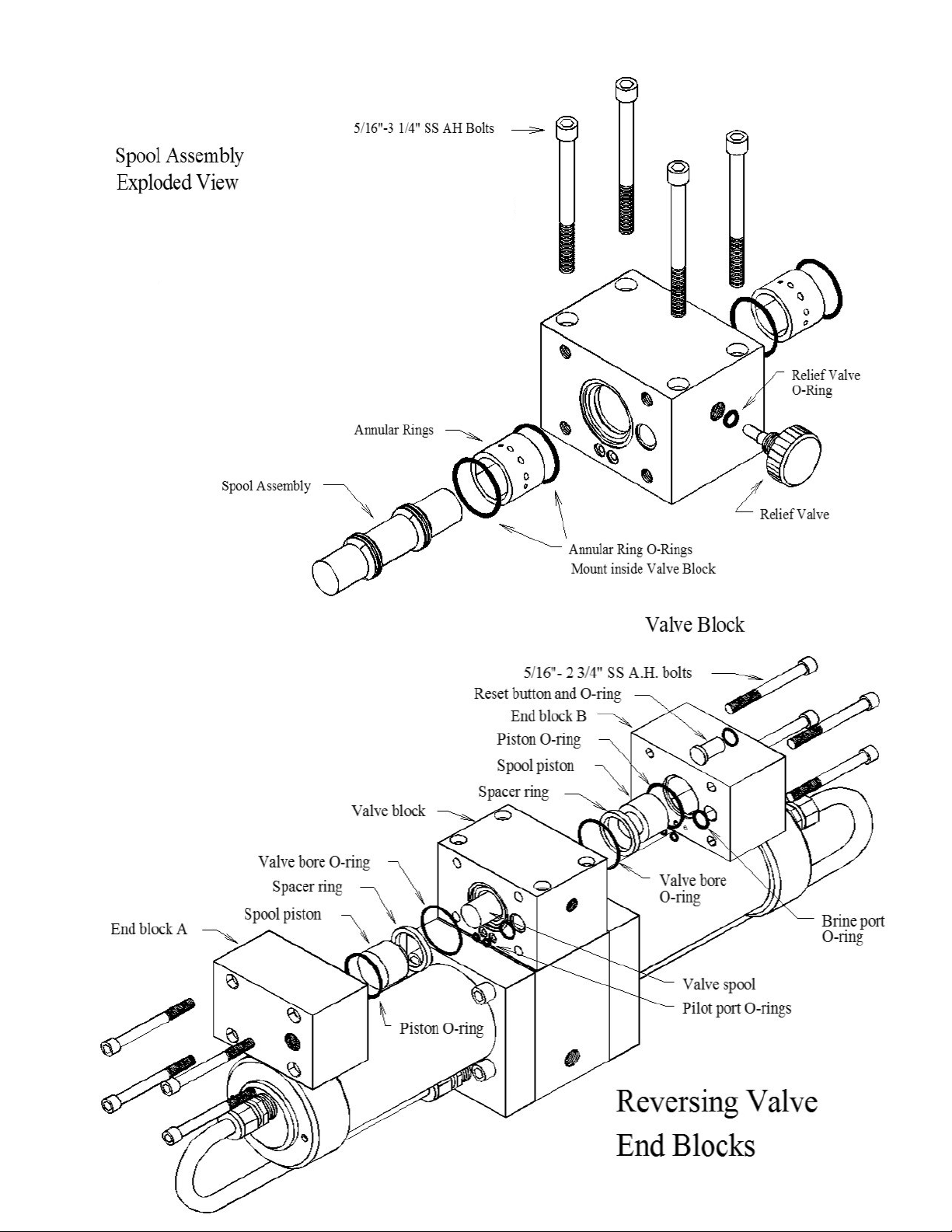
62
HD-CPS-5/16X3
KIT-HP-10VSA
HP-TB-ARP
SO-HPP-AR1
SO-HPP-RV
HP-TB-BV
HD-CPS-5/162.75
SO-HPP-SP
HP-TB-VSP
HP-TB-SR
SO-HPP-VB
SO-HPP-PLP
SO-HPP-VP
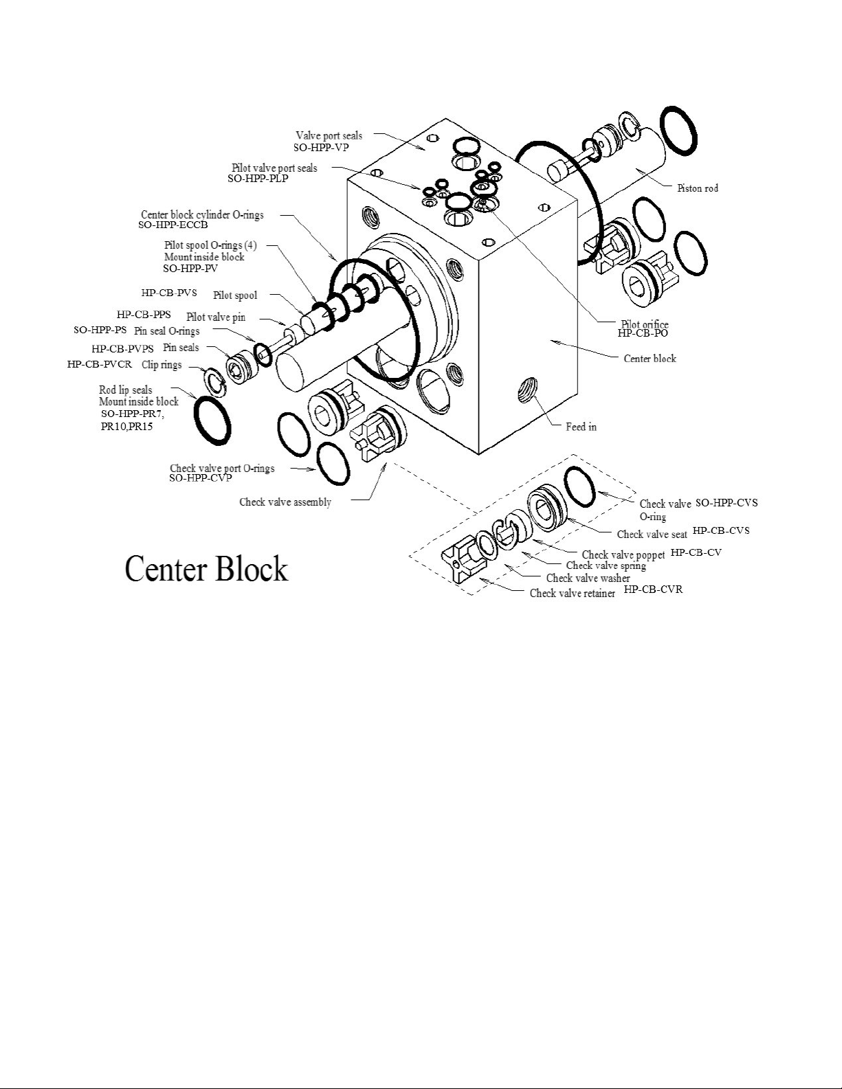
63
Parts
HP-CYL-3/4R,
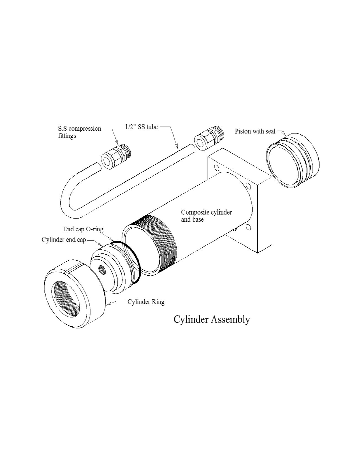
64
PL-MTS-3/8X1/2B
HP-CYL-SST
HP-CYL-CCA SO-HPP-ECCB
HP-CYL-EC
HP-CYL-R
HP-CYL-PT
Parts

65

66
SPECTRA WATERMAKERS LIMITED LIFETIME WARRANTY
THIS LIMITED WARRANTY APPLIES TO THE ORIGINAL OWNER OF THE WATERMAKER AND IS NOT TRANSFERRABLE
For warranty information regarding products sold within the European Union please contact
europe@spectrawatermakers.com.
This limited product warranty is provided by Katadyn Desalination LLC, a Business Unit of the Katadyn
Group. (“Manufacturer” of “We” or “Our”) to the original, consumer owner of the product (“You” or
“Your”) with which this limited product warranty is provided (the “Product.”)
The Manufacturer warrants to You that the product will be free from defects in material and workmanship
under normal use and regular service and maintenance, subject to the exclusions described below, for a period
of
year (the “Warranty Period”) after date of installation, or 15 months after the shipment date, whichever
comes first. This warranty will be extended for an additional 12-month period when the product is installed
and commissioned by a Katadyn Desalination Authorized Installer. A Spectra Watermakers Commissioning
Report must also be returned and approved by the factory. The Spectra Clark Pump has a Limited Lifetime
Warranty on Marine systems to the original consumer owner of the product, not inclusive of repair or
replacement parts due to wear over time. If the Spectra Clark Pump is used in a Landbased application, the
product warranty is provided for a period of
year (the “Warranty Period”) after date of purchase (if purchaser
is installing system) or date of commissioning (if Spectra dealer is installing system).
You will be required to show written documentation supporting the date of purchase or date of
commissioning. If you are unable to provide documentation supporting the date of purchase or
commissioning, the warranty period shall be based on the product’s date code and will be determined by the
Manufacturer’s sole and absolute discretion.
WHAT IS COVERED
Katadyn Desalination LLC. warrants, for the period defined above, that the Product will be free from defects
in materials and/or workmanship and will conform to Manufacturers published specifications if installed
and maintained in accordance with the Manufacturers Instructions.
WHAT IS NOT COVERED
The Warranty does not include service, repair, or replacement to correct damage caused by improper
installation, maintenance, improper connection with water systems, external electrical fault, accident,
alteration, misuse, abuse, neglect, negligence, (other than Manufacturer’s), acts of God, failure to install or
maintain the product in accordance with the Manufacturers instructions.
DAMAGED OR MISSING PRODUCT
You must examine the Product upon receipt and notify Katadyn Desalination LLC. if any item is damaged or
missing within 30 days from the date of the delivery. Damage due to freight must be reported to Katadyn
Desalination LLC. and to the freight carrier within 24 hours of delivery.

67
SOLE WARRANTY
THE PRODUCTS AND ARE IN LIEU OF AND
EXCLUDE ALL OTHER WARRANTIES, EXPRESS OR IMPLIED, ARISING BY OPERATION OF LAW OR
PRODUCTS ARE SPECIFICALLY DESIGNED AND/OR MANUFACTURED BYMANUFACTURER FOR
YOUR USE OR PURPOSE.
WHAT WE WILL DO TO CORRECT PROBLEMS
If You return the defective product during the warranty period and in accordance with the instructions
contained herein, shipping prepaid, the Manufacturer shall, at its option and as Your exclusive
remedy, repair, correct or replace the product at no charge if the product is found by the
Manufacturer to be a valid warranty claim, in Manufacturer’s sole discretion. Replacement product
may be refurbished and/or different models but will be functionally equivalent to the product or
hardware being replaced. Product repaired or replaced during the warranty period shall be covered
by the foregoing warranty for the remainder of the original warranty period or ninety (90) days from
the date of shipment or purchase, whichever is longer. Contact your Dealer or the Manufacturer’s
Customer Service at 415-526-2780 to obtain a returns materials authorization (RMA #).
HOW TO MAKE A WARRANTY CLAIM
If You discover any warranty related issues after 30 days, or You have questions concerning Your
product or how to determine when service is needed, please contact your local dealer or contact the
Manufacturer’s Technical Support at 415-526-2780 or email the Manufacturer at
techsupport@spectrawatermakers.com.
The following information must be provided as part of Your
warranty claim: your name, address, phone number, Your products’ model number, Your product’s 4-
digit serial number, and if necessary, upon request, written confirmation of the date shown on Your
purchase receipt and the purchase price paid for the product. All products being returned to the
Manufacturer must have a return material authorization (RMA) number to be processed. Any item
returned to the Manufacturer without an RMA number will not be accepted by the Manufacturer
Contact your Dealer or Customer Service to obtain an RMA number. Once we have received Your
returned product, we will determine, in our sole and absolute discretion, whether Your claim is covered
by, or excluded from, this limited warranty. Repairs or modifications made to the product by other than
the Manufacturer will nullify this limited warranty. Coverage under this limited warranty is
conditioned at all times
upon the original purchaser’s compliance with these required notification and repair procedures.
LIMITATION OF LIABILITY TO THE FULLEST EXTENT PERMITTED BY LAW, IN NO EVENT, SHALL
MANUFACTURER OR ITS AUTHORIZED SERVICE REPRESENTATIVES BE LIABLE FOR ANY
INCIDENTAL, SPECIAL, INDIRECT, OR CONSEQUENTIAL DAMAGES, INCLUDING ANY ECONOMIC
LOSS, WHETHER RESULTING FROMNONPERFORMANCE, USE, MISUSE OR INABILITY TO USE
THE PRODUCT OR THE MANUFACTURER'S OR ITS AUTHORIZED SERVICE REPRESENTATIVE’S
NEGLIGENCE. THE MANUFACTURER SHALL NOT BE LIABLE FOR DAMAGES CAUSED BY DELAY
IN PERFORMANCE AND, IN NO EVENT, REGARDLESS OF THE FORM OF THE CLAIM OR CAUSE OF
ACTION (WHETHER BASED IN CONTRACT, INFRINGEMENT, NEGLIGENCE, STRICT LIABILITY,
OTHER TORT OR OTHERWISE), SHALL MANUFACTURER’S LIABILITY TO YOU EXCEED THE
PRICE PAID BY THE ORIGINAL OWNER FOR THE MANUFACTURER’S PRODUCT.
The term “consequential” damages shall include, but not be limited to, loss of anticipated profits,
business interruption, loss of use or revenue, the cost of capital or loss or damage to property or
equipment. Some states do not allow the exclusion or limitation of incidental or consequential
damages, so the above limitation may not apply to you. This limited warranty gives you specific legal
rights, and you may also have may other rights which vary from State to State.

68
Spectra Product Registraon Form
Registraon (To be completed by owner)
Boat model or type (i.e. Leopard 44, Beneteau 55' powerboat, catamaran, powercat, 42’ sailboat…)
______________________________________________________________________________
What type of boang will you be doing and what will the watermaker primarily be used for:
________________________________________________________________________________________
________________________________________________________________________________________
__________________________________________________________
Submission for Approval:
Please submit this document along with the Installaon and Commissioning Reports to Spectra
Watermakers for approval. Submissions can be submied online, scanned and emailed, or mailed directly
to the factory. Spectra Watermakers Technical Support will email the original owner and the authorized
distributor with the status of submission.
Web-Based Format (Preferred opon):
spectrawarranty.formstack.com/forms/product_registraon
spectrawarranty.formstack.com/forms/spectra_install_commissioning_report
Email:
TechSuppor[email protected]
Phone: +1(415) 526-2780
Address: Katadyn Desalinaon
Technical Department
2220 S. McDowell Blvd Ext
Petaluma, CA 94954
USA
Please keep a copy of these reports for your records.
Any commissioning/install report (and additional 12 month warranty) may be rejected at the
sole discretion of Spectra Watermakers if the system is not installed correctly.
System Details:
Model ________________________ Date of install: ______________________________
4-digit S/N___________ Clark Pump S/N: _____________ Voltage_______
Dealer/distributor:____________________ Boat Location:___________ max speed:______
Original Owner Details:
Name:_________________________________ Phone Number:________________________
Email Address:________________________________________________________________
Address (Optional):____________________________________________________________
____________________________________________________________________________
____________________________________________________________________________
CUT HERE

69

70
Spectra Watermakers Installaon Report
(To be completed by authorized installer)
INLET
□ Inlet Seacock is below waterline
□ Inlet Seacock is dedicated
□ Inlet Seacock is shared
□ Inlet Thru-Hull forward facing scoop
□ Has strainer
□ Has diving snorkel
□ Sea chest
□ Other
Thru Hull Size: ____________IN/CM
Approximate locaon on vessel and notes:_____________________________________
_______________________________________________________________________
FEED PUMP MODULE
□ Feed pump module is mounted upright
□ Clearance for lter cartridge changes
□ Intake hoses are free of kinks
□ Pressurized domesc water is connected to carbon lter
Distance from waterline: ________FT/M above¨/below¨ the waterline
HIGH PRESSURE MODULE and BRINE DISCHARGE
□ Pressure relief valve is accessible
□ Brine discharge has no obstrucons and vents to atmosphere
Notes:___________________________________________________________________
________________________________________________________________________
PRODUCT WATER TUBING
□ Product water ows into top of freshwater tank
□ Freshwater tank is vented
The following checklist is designed to confirm that the watermaker installation meets Spectra
standards. Fill out the checklist as completely as possible. Check any boxes that apply and
note any concerns. Please document any discrepancies or concerns with photos.
INSTALLATION SIGN OFF
Technician’s Name: __________________________________________ Date: _____________
Technician’s Signature: __________________________________________________________
Distributor/Dealer_______________________________________________________________
CUT HERE

71

72
Spectra Watermakers Commissioning Report – Page 1
(To be completed by authorized installer)
Fill out the below checks as completely as possible. Check any boxes that apply and note any concerns.
PURGE
□ Storage Chemicals have been purged with PRV open
Length of purge: _______Minutes
□ Diversion Valve is up, in reject posion
RUN HIGH MODE CHECKS
Product Flow: _____________ GPH/LPH
Conrmed Product Flow Rate ___________GPH/LPH
□ Technician Flow meter. Brand________________
□ Hand Measurement _______Gal/Liters in _____SEC/MIN
Product Quality: __________ PPM
□ Conrmed product quality with handheld TDS meter
Feed Pressure: __________ PSI/BAR
Brine Flow Rate: _______________ GPM/LPM
Measurement taken with:
□ Technician Flow meter. Brand_________________
□ Hand Measurement: _______Gal/Liters in _____SEC/MIN
Notes:_________________________________________________________________
______________________________________________________________________
FRESHWATER FLUSH
□ Freshwater Flush solenoid valve opens
When seacock is open, what is the ppm of brine discharge at the end of the ush_______
Flush duraon is ________Minutes
□ Needed to change ush me
Notes:________________________________________________________________
______________________________________________________________________
*If the system does not have a dedicated forward-facing scoop type thru-hull or will be on a vessel that moves
faster than 15 knots the system needs to complete the following sea trial checks. Spectra Watermakers
reserves the right to require a sea trial from any customer before approving a commissioning report.
SEA TRIAL
□ Watermaker will ush while underway
□ Watermaker will start while underway
While the vessel is underway moving _______KNOTS/MPH/KPH the watermaker is producing _______ GPH/
LPH at ______PPM
The following checklist is designed to conrm that the watermaker installaon meets Spectra
standards and that the system is performing at specicaon.
CUT HERE

73
Spectra Watermakers Commissioning Report – Page 2
OWNER EDUCATION
Owner has been trained on the following:
Know locaons of
□ Seacock/Thru-hull
□ Sea strainer
□ Feed Pump Module
□ Prelter Module
□ Freshwater Flush Module
□ High Pressure Module
□ Control Box and RUN MANUAL toggle switch
□ Clark Pump Pressure Relief valve
□ Product water inlet to Freshwater Tank
□ Brine Discharge locaon
□ Service hoses and storage chemicals
□ User Manual
□ How to power the watermaker o and on at the main breaker.
□ How to run the watermaker.
□ How to freshwater ush and the importance of freshwater ushing.
□ Knows when the ships domesc freshwater pump is on.
□ Knows which prelter cartridges to use and how to change them.
□ Knows how to service the sea strainer module.
□ Knows where the carbon block lter is and is familiar with (6 months) service frequency.
□ Knows how to run the system via “RUN MANUAL.” Including knowing how to bypass the diversion valve and sample the
product water before it enters the tank.
□ Understands the risks of running the system in run manual.
□ Have visually seen the overboard brine discharge (Should know when the system is pumping water).
□ Know where freshwater enters the tank, would be able to manually sample/taste water if necessary.
□ Understand when the Clark Pump is under pressure and cycling.
□ Have seen how the service hoses and bucket are used to circulate seawater or freshwater through the system.
□ Have heard the dierence speeds of the vane pump (the dierence between Run Hi and Service speed.)
Notes:_______________________________________________________________________________________________
_____________________________________________________________________________________________________
_____________________________________________________________________________________________________
_____________________________________________________________________________________________________
_____________________________________________________________________________________________________
____________________________________
CUT HERE

74