I
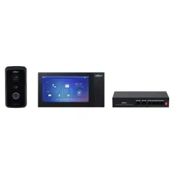
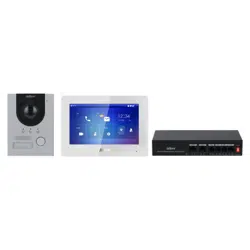
Villa Door Station
User’s Manual
V1.0
.3

I
Foreword
General
This manual introduces the installation, functions and operations of the villa door station device
(hereinafter referred to as "the VTO"). Read carefully before using the device, and keep the manual safe
for future reference.
Safety Instructions
The following categorized signal words with defined meaning might appear in the manual.
Signal Words Meaning
DANGER
Indicates a high potential hazard which, if not avoided, will result in
death or serious injury.
WARNING
Indicates a medium or low potential hazard which, if not avoided,
could result in slight or moderate injury.
CAUTION
Indicates a potential risk which, if not avoided, could result in
property damage, data loss, lower performance, or unpredictable
result.
TIPS
Provides methods to help you solve a problem or save you time.
NOTE
Provides additional information as the emphasis and supplement to
the text.
Revision History
Version Revision Content Release Date
V1.0.3 Revised “Important Safeguards and Warnings”. December 2022
V1.0.2 Revised facade layout description. November 2022
V1.0.1
Revised room number configuration in facade
layout module.
June 2022
V1.0.0 First release. December 2021
Privacy Protection Notice
As the device user or data controller, you might collect the personal data of others such as their face,
fingerprints, and license plate number. You need to be in compliance with your local privacy protection
laws and regulations to protect the legitimate rights and interests of other people by implementing
measures which include but are not limited: Providing clear and visible identification to inform people
of the existence of the surveillance area and provide required contact information.
About the Manual
The manual is for reference only. Slight differences might be found between the manual and the

II
product.
We are not liable for losses incurred due to operating the product in ways that are not in
compliance with the manual.
The manual will be updated according to the latest laws and regulations of related jurisdictions.
For detailed information, see the paper user’s manual, use our CD-ROM, scan the QR code or visit
our official website. The manual is for reference only. Slight differences might be found between
the electronic version and the paper version.
All designs and software are subject to change without prior written notice. Product updates
might result in some differences appearing between the actual product and the manual. Please
contact customer service for the latest program and supplementary documentation.
There might be errors in the print or deviations in the description of the functions, operations and
technical data. If there is any doubt or dispute, we reserve the right of final explanation.
Upgrade the reader software or try other mainstream reader software if the manual (in PDF
format) cannot be opened.
All trademarks, registered trademarks and company names in the manual are properties of their
respective owners.
Please visit our website, contact the supplier or customer service if any problems occur while
using the device.
If there is any uncertainty or controversy, we reserve the right of final explanation.

III
Important Safeguards and Warnings
This section introduces content covering the proper handling of the device, hazard prevention, and
prevention of property damage. Read carefully before using the device, and comply with the
guidelines when using it.
Operation Requirements
●
Check whether the power supply is correct before use.
●
Do not unplug the power cord on the side of the device while the adapter is powered on.
●
Operate the device within the rated range of power input and output.
●
Transport, use and store the device under allowed humidity and temperature conditions.
●
If the device is powered off for longer than a month, it should be placed in its original package and
sealed. Make sure to keep it away from moisture, and store it under allowed humidity and
temperature conditions.
●
Do not drop or splash liquid onto the device, and make sure that there is no object filled with liquid
on the device to prevent liquid from flowing into it.
●
Do not disassemble the device without professional instruction.
Installation Requirements
●
Do not connect the power adapter to the device while the adapter is powered on.
●
Strictly comply with the local electric safety code and standards. Make sure the ambient voltage is
stable and meets the power supply requirements of the device.
●
Do not connect the device to two or more kinds of power supplies, to avoid damage to the device.
●
Improper use of the battery might result in a fire or explosion.
●
Personnel working at heights must take all necessary measures to ensure personal safety including
wearing a helmet and safety belts.
●
Do not place the device in a place exposed to sunlight or near heat sources.
●
Keep the device away from dampness, dust, and soot.
●
Install the device on a stable surface to prevent it from falling.
●
Install the device in a well-ventilated place, and do not block its ventilation.
●
Use an adapter or cabinet power supply provided by the manufacturer.
●
Use the power cords that are recommended for the region and conform to the rated power
specifications.
●
The power supply must conform to the requirements of ES1 in IEC 62368-1 standard and be no
higher than PS2. Please note that the power supply requirements are subject to the device label.
●
The device is a class I electrical appliance. Make sure that the power supply of the device is
connected to a power socket with protective earthing.

IV
Table of Contents
Foreword ............................................................................................................................................................ I
Important Safeguards and Warnings ............................................................................................................. III
1 Initializing the VTO ........................................................................................................................................ 1
Web .................................................................................................................................................................................................. 1
DMSS APP ..................................................................................................................................................................................... 3
2 Login and Resetting Password ..................................................................................................................... 7
Login ............................................................................................................................................................................................... 7
Resetting Password ................................................................................................................................................................... 7
3 Home Page ..................................................................................................................................................... 9
4 Local Settings .............................................................................................................................................. 10
Basic Settings ............................................................................................................................................................................. 10
4.1.1 Device Properties & Events...................................................................................................................................... 10
4.1.2 Facade Layout .............................................................................................................................................................. 11
Video & Audio ............................................................................................................................................................................ 13
Access Control Settings ......................................................................................................................................................... 16
4.3.1 Local ................................................................................................................................................................................. 16
4.3.2 RS-485 ............................................................................................................................................................................. 17
System .......................................................................................................................................................................................... 17
Security ........................................................................................................................................................................................ 19
Onvif User .................................................................................................................................................................................... 21
Update .......................................................................................................................................................................................... 22
Upload File .................................................................................................................................................................................. 22
Legal Info ..................................................................................................................................................................................... 23
5 Household Setting....................................................................................................................................... 24
VTO No. Management ............................................................................................................................................................ 24
VTH Management .................................................................................................................................................................... 25
Personnel Management ........................................................................................................................................................ 26
VTS Management ..................................................................................................................................................................... 29
Status ............................................................................................................................................................................................ 30
6 Network........................................................................................................................................................ 31
Basic .............................................................................................................................................................................................. 31
6.1.1 TCP/IP .............................................................................................................................................................................. 31
6.1.2 Port ................................................................................................................................................................................... 32
6.1.3 Cloud service ................................................................................................................................................................ 33
UPnP .............................................................................................................................................................................................. 33
6.2.2 Enabling UPnP Services ............................................................................................................................................ 33
6.2.3 Adding UPnP Services ............................................................................................................................................... 34
SIP Server .................................................................................................................................................................................... 34
Wi-Fi ............................................................................................................................................................................................... 36
Firewall ......................................................................................................................................................................................... 37
7 Log Management ........................................................................................................................................ 38
Call ................................................................................................................................................................................................. 38
Alarm ............................................................................................................................................................................................ 38
Unlock .......................................................................................................................................................................................... 39

V
Log ................................................................................................................................................................................................. 39
8 Button Model Configuration ...................................................................................................................... 40
Cable Connection .................................................................................................................................................................... 40
VTH Configuration ................................................................................................................................................................... 40
Cybersecurity Recommendations ............................................................................................. 42
1
1 Initializing the VTO
You can initialize the VTO on the web or through DMSS app, depending on which network connection
your model support.
Table 1-1 Initialization type
Network Connection Initialization Through Web Initialization Through DMSS App
Wi-Fi connection No Yes
Wired connection Yes Yes
Web
For first-time login, you need to initialize the VTO.
Power on the VTO.
Go to the default IP address (192.168.1.108) of the VTO.
Make sure that the IP address of your PC is on the same network segment as the VTO.
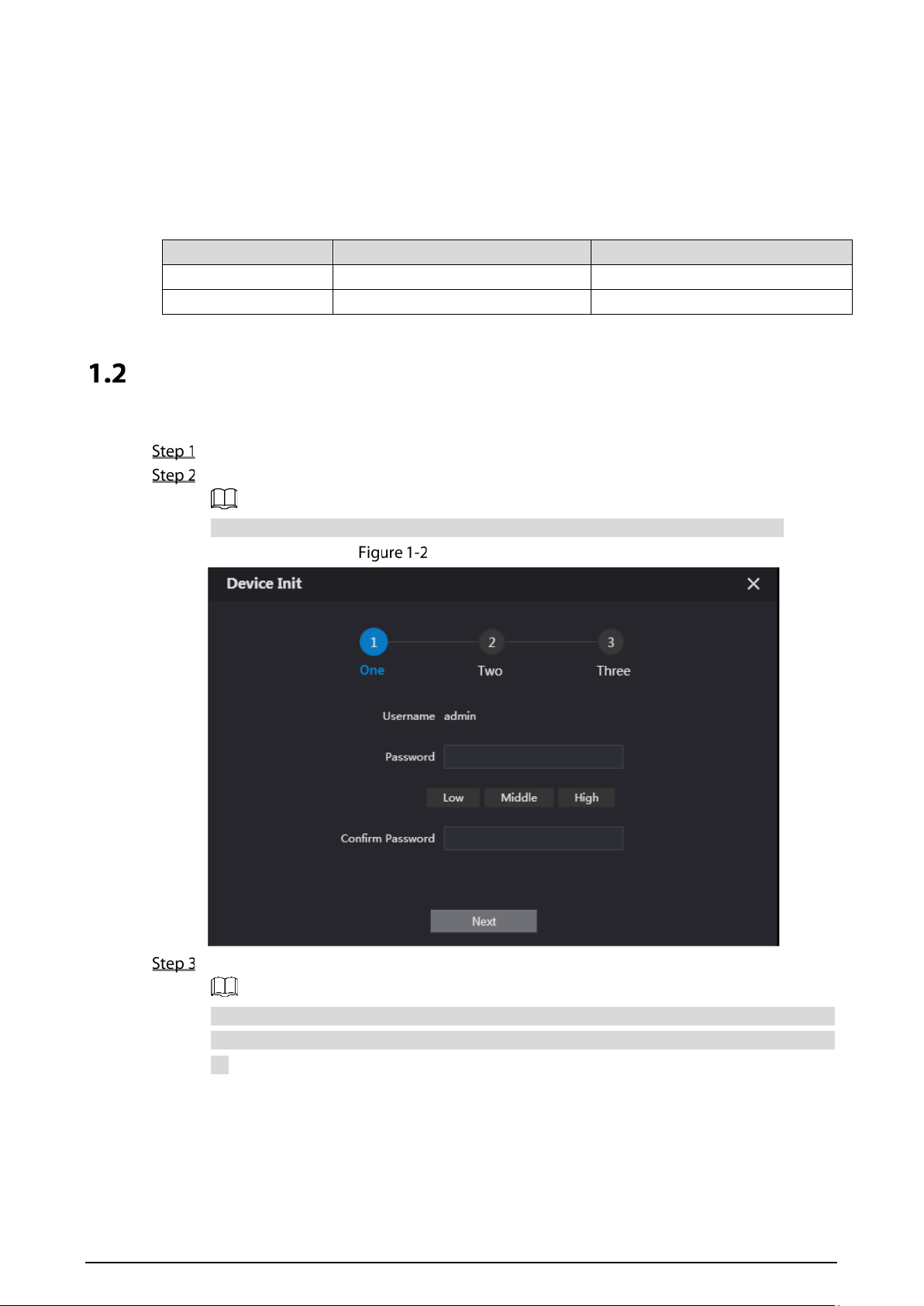
Device initialization
On the Device Init page, enter and confirm the password, and then click Next.
The password must consist of 8–32 non-blank characters and contain at least two types of the
following characters: Uppercase, lowercase, numbers, and special characters (excluding ' " ; :
&).

2
Set an email address
Select the Email checkbox and enter an email address for resetting password.
Click Next.
Initialization successful
Click OK to go to the login page.
Enter the username (admin by default) and password to log in to the web page.
Login page
3
DMSS APP
If your model only supports Wi-Fi connection to the network, you can only initialize the VTO on the
DMSS app. For detailed operation of the app, refer to its User’s Manual.
Prerequisites
You have downloaded the DMSS in the APP Store (iOS) or Google Play (Android), and have created an
account and logged into the app.
Operations
Power on the VTO.
Enable hotspot on the VTO through pressing and holding the call button on the VTO until you
heard the voice prompt.
The hotspot function is to enable you connect the VTO to the network through AP
configuration on the app.
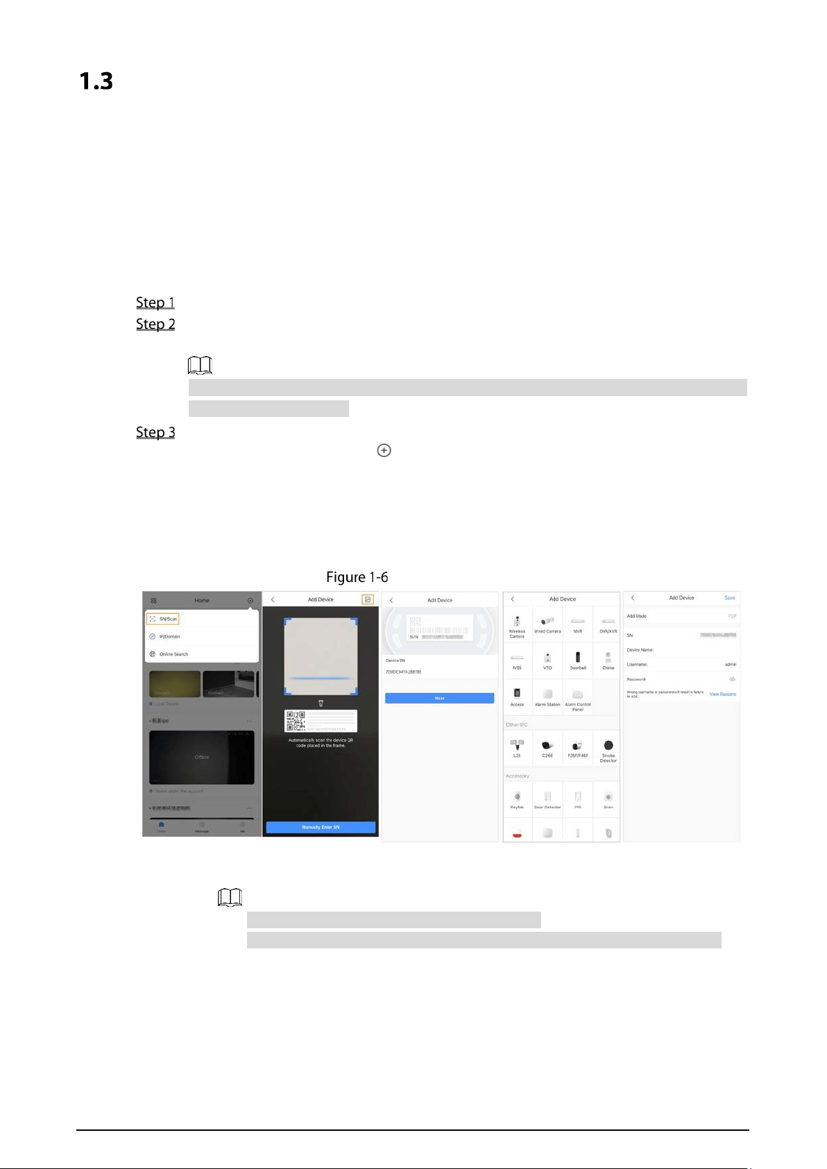
Add the VTO to the DMSS app.
1) On the Home screen, tap , and then select SN/Scan.
2) Add a VTO.
You can add through scanning the QR code at the rear panel of the VTO.
3) The SN number of the VTO appears automatically, and then tap Next.
4) Select device type as VTO, and then the device information appears.
5) Tap View Reasons.
Add VTO to DMSS
6) Configure network by switch networking to AP Configuration, and then tap Next.
7) Connect your phone to the hotspot you just enabled on the VTO.
The hotspot name is the SN number of your VTO.
The current page will move on to the next step automatically after connection.

4
AP configuration
Complete initialization based on instructions on the app.
1) Enter the password you planned for the VTO, and confirm it, and then tap Next.
2) Select Cloud Access and Auto-check, and then tap OK.
The initialization process is completed.
Initialization
Connect the VTO to the network through Wi-Fi.
1) Select an available Wi-Fi.
2) Enter the password and tap Next. Wait for the VTO to connect to the router.

5
Wi-Fi connection
Configure device name, and tap Save.
Configure device name
View monitoring video from the camera on the VTO.

6
Monitor

7
2 Login and Resetting Password
Login
Before login, make sure that the PC is on the same network segment as the VTO.
Go to the IP address of the VTO in the browser.
For first-time login, enter the default IP (192.168.1.108). If you have multiple VTOs, we
recommend that you change the default IP address (Network > Basic) to avoid conflict.
Enter admin as the username, and enter the password you set during initialization, and then
click Login.
Login
Resetting Password
On the login page, click Forgot Password?, and then click Next.
Reset the password
Scan the QR code, and then you will get a string of numbers and letters.
Send the string to the email account displayed on the page, and then the security code will
be sent to the email address configured during initialization.

8
Enter the security code in the input box, and then click Next.
If you did not set an email address during initialization, contact your supplier or
customer service for help.
The security code will be valid only for 24 hours upon receipt.
If you enter the wrong security code for 5 consecutive times, your account will be locked
for 5 minutes.
Enter and confirm the new password, and then click OK.

9
3 Home Page
Home Page
Table 3-1 Home page introduction
No. Function Description
1 General function
: Change the password and your email address.
: Go to the home page.
: Log out, restart
the VTO or restore the VTO to factory
settings.
If you restore the VTO to factory settings, all data except external
storage will be deleted. You can format the SD card to delete the data
in it.
2 VTO information
View the information of the VTO and the system.
3 System information
4
Configuration
manager
Export or import VTO configuration or user information.
5 Function
Configure parameters for different functions.
The web page and the functions might be different depending on
the model.

10
4 Local Settings
This chapter introduces the detailed configuration of the VTO.
Slight differences might be found in different models.
Basic Settings
4.1.1 Device Properties & Events
Select Local Settings > Basic.
Configure the parameters.
Basic
Table 4-1 Basic parameter description
Parameter Description
Device Type Select Villa Station or Small Apartment.
Center Call No.
The default phone number for the management center is 888888, and
you can set it to any number with up to 9 digits.
Device Name
When other devices are monitoring this VTO, the device name will appear
on the monitoring image.
Calling Center Period
Time period in which the management center can be called. Configure
the time and enable the function so that you will receive calls only in that
perioed.

11
Parameter Description
Villa Call No. Used to call VTHs.
No.
Used to differentiate each VTO, and we recommend you set it according
to unit or building number, and then you can add VTOs to the SIP server
by using their numbers.
The number cannot be changed when the VTO serves as the SIP server.
Periods in which Calls
can be Made
Configure the time if you only want to receive calls from VTH during a
specific period.
Group Call
Enable it on the VTO that works as the SIP server, and when a main VTH
receives a call, all extension VTHs will also receive the call.
Storage Point SD card by default.
Total SD Card
Capacity
Displays the total and used capacity of the SD card. You can click Format
to delete all the data in the SD card.
SD Used Capacity
Format
Auto Capture
(Unlock)
When the door is unlocked, the VTO will take two snapshots and save
them to the SD card.
Auto Capture (Calling)
Take a snapshot and save it in the SD card of the VTO when the VTO is
calling.
Upload Video
Messages
When enabled:
If an SD card is inserted in both the VTH and VTO, the video message
will be saved both in the SD cards of the VTH and the VTO.
If an SD card is only inserted in the VTH or the VTO, the video message
will be saved only in the SD card of the VTH or the VTO.
If no SD card is inserted in the VTH or VTO, no video message will be
saved.
Auto Recording (Call)
Take recording when the VTO is in a call, and save the recording in the SD
card of the VTO.
Click Save.
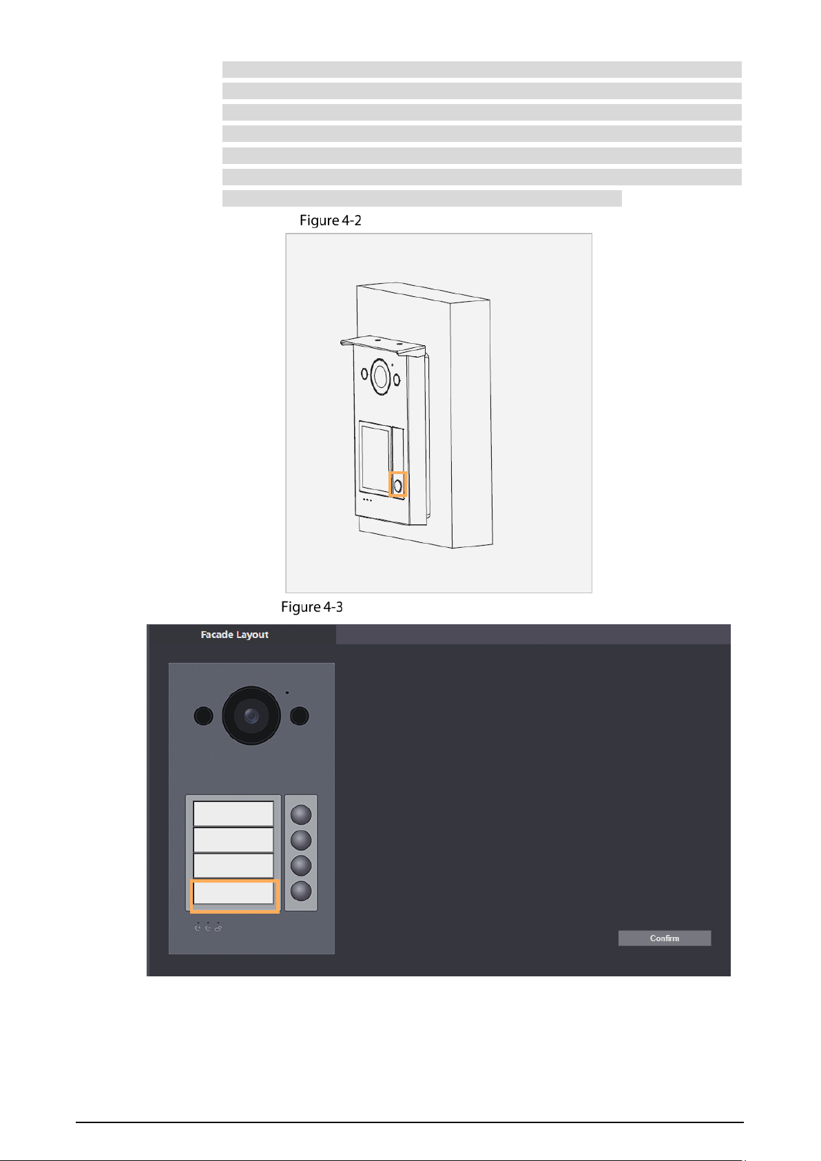
4.1.2 Facade Layout
This function is only available for the VTO model with multiple buttons (1 button, 2buttons and 4
buttons). Here is an example of configuration for the VTO that has one button installed on its device.
Procedures
Log in to the web page of the VTO.
Select Local Settings > Basic.
In the Facade Layout section, click the nameplates next to where you have installed the
button, and then select the room number from the Room List you want to bind. For example,
9901.
The VTH room numbers in the Room List are configured in Household Setting > VTH
Management.
12
You need to configure the room number based on your installation of buttons. For
example, if you have only installed one button next to the first nameplate, then you
need to click the module of first nameplate to configure the room number on the web
page. If you have installed one button next to the fourth nameplate, then you need to
click the module of fourth nameplate to configure the room number on the web page.
Keep the above configuration rule when you install 2 buttons or 4 buttons on the VTO
and configure the corresponding room numbers on the web page.
Fourth button installation
Configure the fourth nameplate

13
Room list
Click Save to save the selected room number.
Configure the fourth nameplate
Click Confirm to save all the settings.
Related Operations
If you want to bind room numbers when you install 2 buttons or 4 buttons for the VTO, repeat Step 3
to Step 4 until you have configured all of the room numbers.
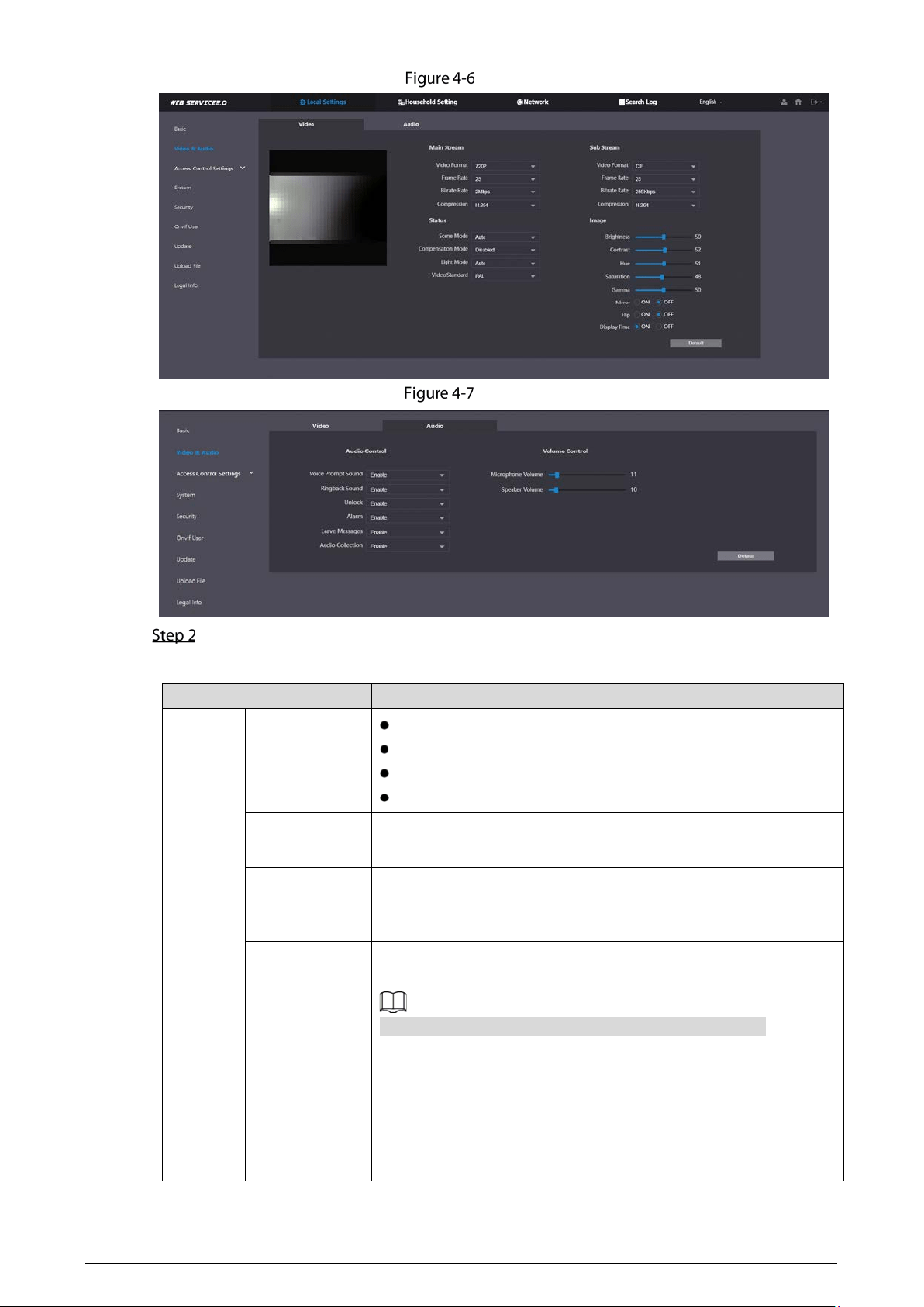
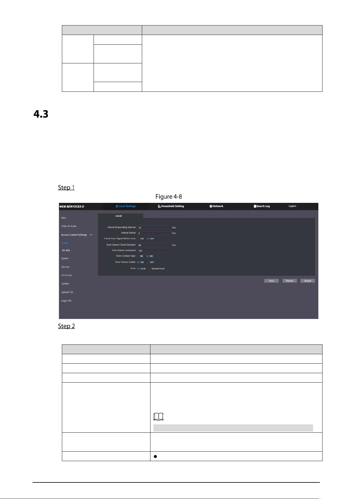
Video & Audio
Configure the video format and quality, and audio of the VTO.
Select Local Settings > Video & Audio.
14
Video
Audio
Configure the parameters, which will take effect upon change.
Table 4-2 Video parameter description
Parameter Description
Main
Stream
Video Format
720P: 1280 × 720.
WVGA: 800 × 480.
D1: 720 × 480.
CIF: 352 × 288.
Frame Rate
The range is 1 to 25. The larger the value, the smoother the video,
but it requires more bandwidth.
Bitrate Rate
Include 768 Kbps, 896 Kbps, 1024 Kbps, 1.25 Mbps, 1.5 Mbps, 1.75
Mbps, 2Mbps and 4 Mbps. The larger the value, the better the
video quality, but it requires more bandwidth.
Compression
H.264.
H.265.
Compared with H.264, H.265 requires smaller bandwidth.
Sub
Stream
Video Format
1080P: 1920 × 1080.
WVGA: 800 × 480.
QVGA: 320 × 240.
D1: 720 × 480.
CIF: 352 × 288.

15
Parameter Description
Frame Rate
The range is 1 to 25. The larger the value, the smoother the video,
but it requires more bandwidth.
Bitrate Rate
Include 224 Kbps, 256 Kbps, 320 Kbps, 384 Kbps, 448 Kbps, 512
Kbps, 640 Kbps, 768 Kbps. The larger the value, the better the video
quality, but it requires more bandwidth.
Compression
H.264.
H.265.
Compared with H.264, H.265 requires smaller bandwidth.
Status
Scene Mode
Select from Auto, Disabled, Sunny and Night. Auto is selected by
default.
Compensation
Mode
BLC: Back light compensation. Improve the clarity of the target
in the image.
WDR: Wide dynamic range. Enhance
the brightness of dark
areas, and reduce the brightness of bright areas to improve the
image.
HLC: High light compensation. Reduce the brightness of the
strong spots to improve the overall image.
Light Mode Select from NO, NC, Auto and Scheduled.
Video Standard
Select PAL or NTSC according to your area.
PAL is mostly used in China and Europe, and NTSC primarily in the
United States and Japan.
Image
Brightness The larger the value, the brighter the image.
Contrast Larger value for more contrast between bright and dark areas.
Hue
Make the color brighter or darker. The default value is made by the
light sensor, and we recommend keeping it default.
Saturation The larger the value, the thicker the color.
Gamma
Changes the picture brightness and improves the picture dynamic
range in a non-linear way. The larger the value, the brighter the
image.
Gain
Adjustment
Amplify the video signal to increase image brightness. If the value is
too large, there will be more noise in the image.
Mirror Display the image with left and right side reversed.
Flip Display the image upside down.
Display Time Display the current time and date on the video image.
Audio
Control
Voice Prompt
Sound
Turn on or off each type of sound.
Ringback
Sound
Adjust the volume as needed.
Alarm
Leave Messages
16
Parameter Description
Unlock
Audio
Collection
Volume
Control
Microphone
Volume
Speaker Volume
Access Control Settings
This section introduces how to configure the two locks connected to the lock port or the RS-485 port
of the VTO.
4.3.1 Local
Select Local Settings > Access Control Settings.
Local
Configure the parameters.
Table 4-3 Local access control parameter description
Parameter Description
Unlock Responding Interval The door can only be unlocked again after the interval.
Unlock Period The time during which the lock stays unlocked.
Check Door Signal Before Lock Select On or Off as needed.
Door Sensor Check Duration
If the door is unlocked longer than the
Door Sensor Check
Duration, the door sensor alarm will be triggered, and the alarm
will be sent to the management center.
You need to install a door contact to configure this parameter.
First Unlock Command
You can connect a third-party phone, such as a SIP phone, to
the VTO, and use the command to open the door remotely.
Door Contact Type NC: Normally closed.
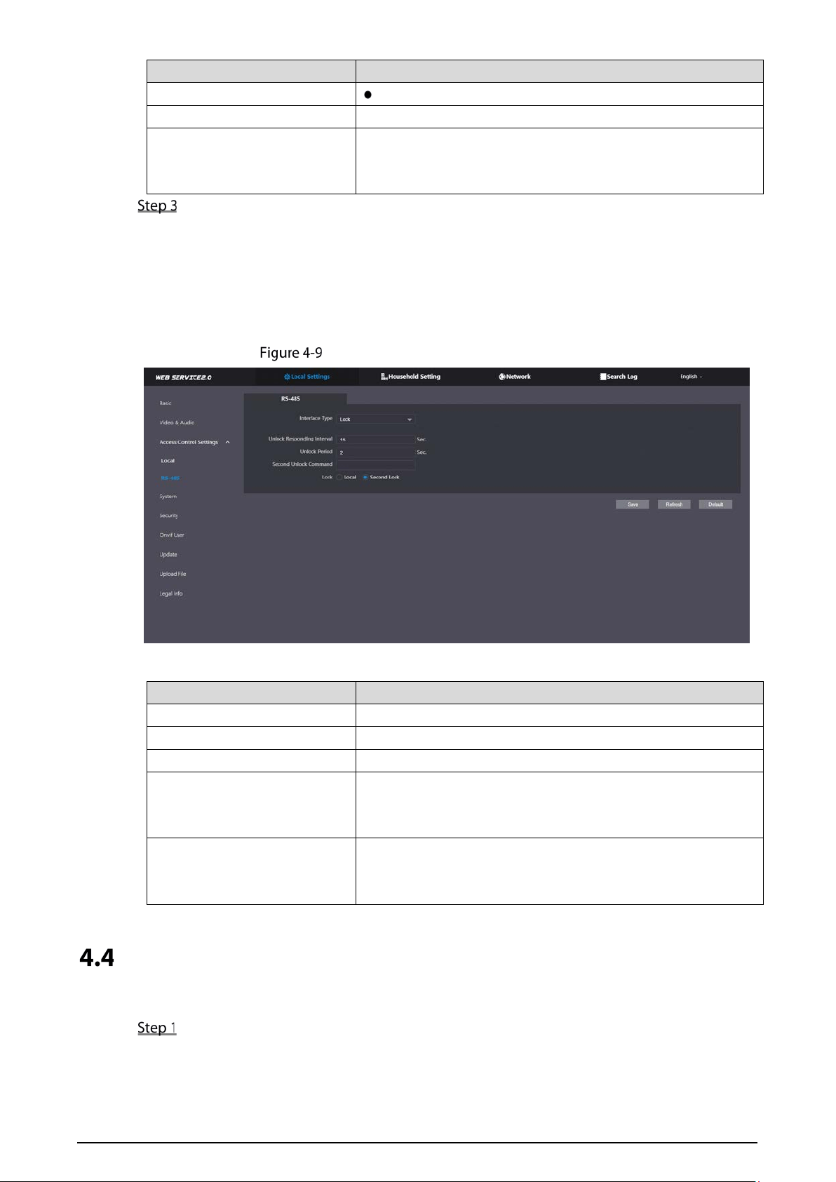
17
Parameter Description
NO: Normally open.
Door Sensor Enable Synchronize door sensor status to indoor monitors (VTHs).
Lock
Local: Local lock.
Second lock: 485 lock.
Select the Lock type to unlock the lock you select.
Click Save.
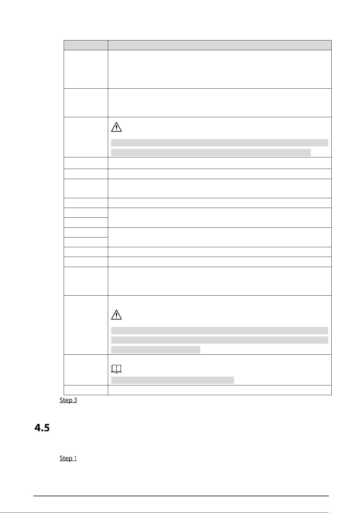
4.3.2 RS-485
Select Local Settings > Access Control Settings, and then configure the parameters of the lock
connected through the RS-485 port.
Lock connected through the RS-485 port
Table 4-4 RS-485 description
Parameter Description
Interface Type Lock by default.
Unlock Responding Interval The door can only be unlocked again after the interval.
Unlock Period The time during which the lock stays unlocked.
Second Unlock Command
You can connect a third-party phone, such as a SIP phone, to
the VTO, and use the command to open the door remotely.
The default command is 456.
Lock
Select the Lock type to unlock the lock you select.
Local: Local lock.
Second lock: 485 lock.
System
Configure time parameters, NTP server, and more.
Select Local Settings > System.

18
System
Configure the parameters.
19
Table 4-5 System parameter description
Parameter Description
Date Format
Select from one of the following:
YYYY-MM-DD
MM-DD-YYYY
DD-MM-YYYY
Time Format
Select from one of the following:
24-Hour
12-Hour
System Time
Changing system time might cause problems on video searching and information
publication. Turn off video recording and auto snapshot before changing it.
Time Zone
Configure the time zone as needed.
Sync with PC Synchronize the VTO system time with your PC.
DST
Daylight saving time. If it is applicable to your area, you need to enable it, and
then configure DST type, start time and end time.
DST Type Select Date or Week as needed, and then configure the specific period.
Start Time
Configure the start time and end time of DST.
End Time
NTP Enable
Enable NTP and enter the IP address of the NTP server, and then the VTO will
syncronize time with the NTP server automatically.
NTP Server
Port NTP server port number.
Interval VTO time update cycle. 30 minutes at most.
Maintenance
Define the time when the VTO will restart automatically.
Choose from Never, Monday, Tuesday, Wednesday, Thursday, Friday, Saturday and
Sunday.
SSH
You can connect debugging devices to the VTO through SSH protocol.
We recommend turning it off, and turn on security mode and outbound service
information protection. See "4.5 Security". Otherwise, the VTO might be exposed
to security risks and data leakage.
Emergency
Maintenance
Enable it for fault analysis and repair.
This function will occupy 8088 and 8087 ports.
NTP Enable Enable NTP so that the device time will be automatically synchronized with server.
Click Save.
Security
Configure functions that involve device security.
Select Local Settings > Security.

20
Security
Configure the parameters.
Table 4-6 Security parameter description
Parameter Description
CGI Enable
Enable the use of CGI command.
We recommend you turn it off. Otherwise, the VTO might be exposed
to security risks and data leakage.
Mobile Push Notification
Send information to the app on the smartphone.
We recommend you turn
it off if you do not need this function.
Otherwise, t
he VTO might be exposed to security risks and data
leakage.
Password Reset If turned off, you will not be able to reset password.
Audio/Video
Transmission Encryption
Encrypt all data during voice or video call.
We recommend you turn it on. Otherwise, the VTO might be exposed
to security risks and data leakage.
ONVIF On
Allow third-party to pull video stream of the VTO through the ONVIF
protocol.
We recommend turning it off. Otherwise, the VTO might be exposed to
security risks and data leakage.
RTSP Over TSL
Output encrypted bit stream through RTSP.
We recommend you turn it on. Otherwise, the VTO might be exposed
to security risks and data leakage.
Outbound Service
Information Protection
Protect your passwords.

21
Parameter Description
We recommend you turn it on. Otherwise, the VTO might be exposed
to security risks and data leakage.
Multicast/Broadcast
Search
Enable it and the VTO will be found by other devices.
We recommend you turn it off. Otherwise, the VTO might be exposed
to security risks and data leakage.
Authentication Mode
Security Mode (recommended): Support logging in with Digest
authentication.
Compatible Mode: Use the old login method.
We recommend you use the security mode. Compatible mode might
expose the VTO to security risks and data leakage.
Password Expires in
Select an expiration period.
We recommend you do not use never. The VTO might be exposed to
security risks and data leakage if you chose that one.
Click Save.
Onvif User
Add accounts for devices to monitor the VTO through the ONVIF protocol.
The operation of deleting an account cannot be undone.
Select Local Settings > Onvif User.
Onvif user
Click Add.
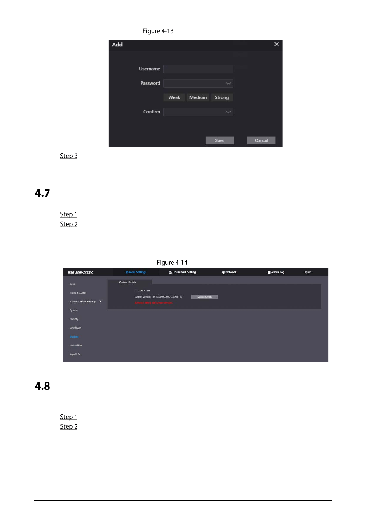
22
Add an Onvif user
Enter the information, and then click Save.
Onvif devices can now monitor the VTO by using the account.
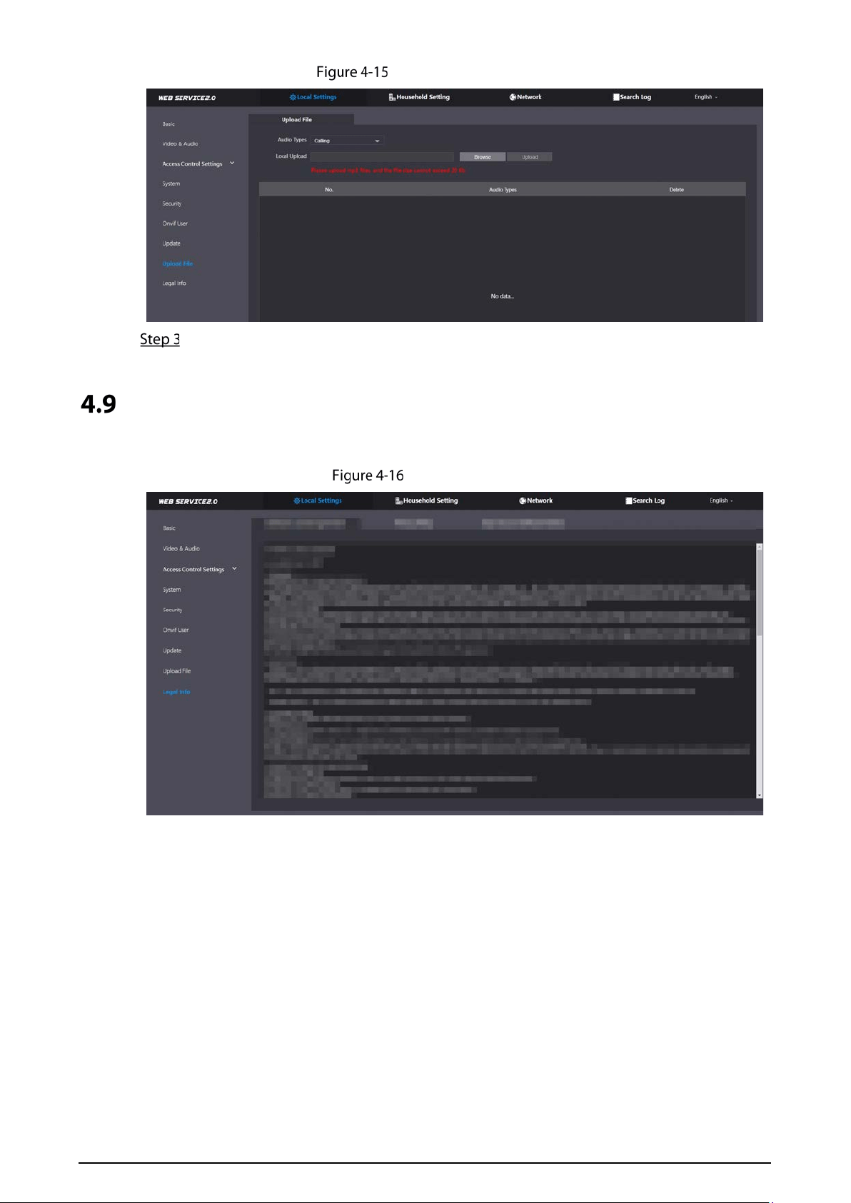
Updating
Select Local Settings > Update.
Select ways to check the update.
Auto Check: Select the function to check automatically whether there is a new system
version.
Manual Check: Select the function to check whether there is a new system version.
Update
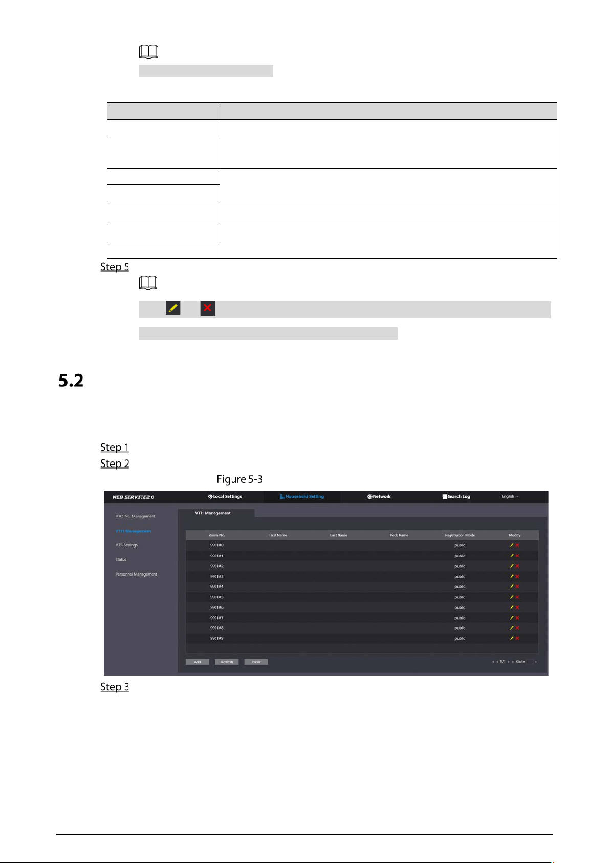
Uploading File
Upload audio file to change the sound when calling, unlocking the door, and more.
Select Local Settings > Upload File.
Select an audio type from the drop-down list, and then click Browse to select the audio file.
23
Change sound prompt
Click Upload.
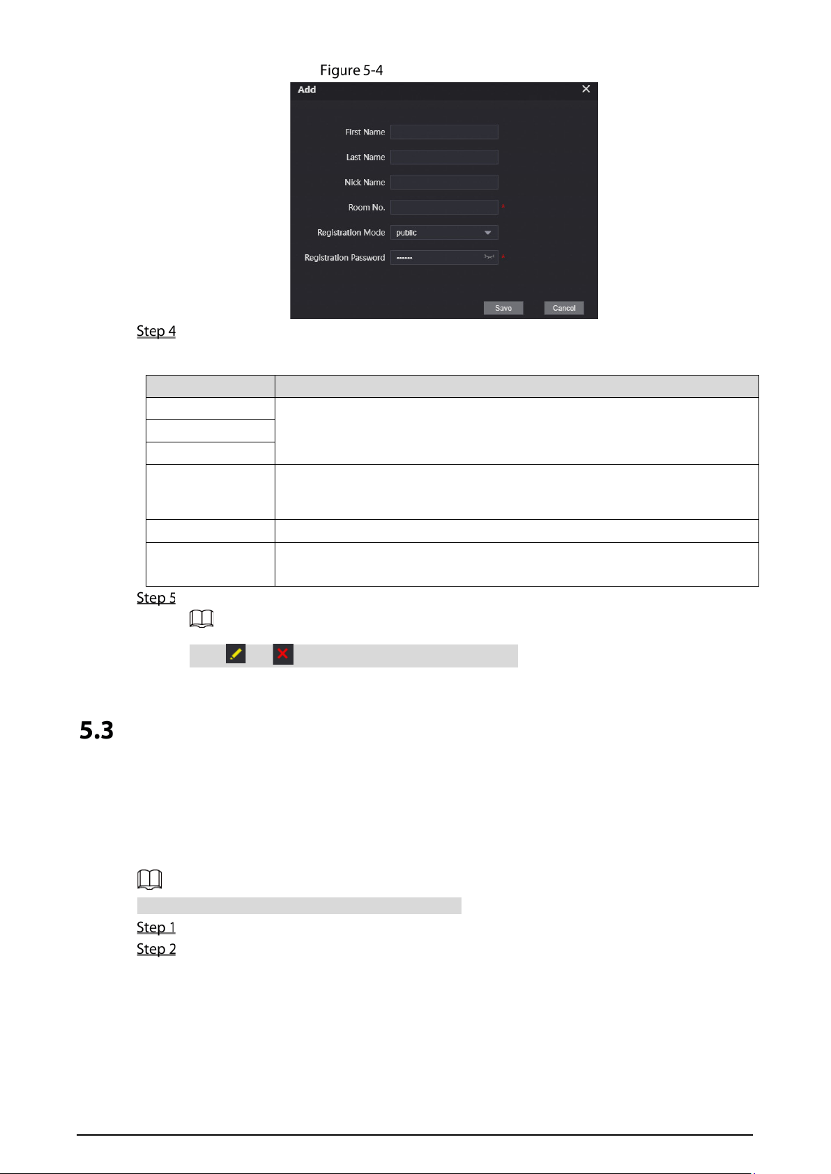
Legal Information
You can view related legal information notices in this section.
Legal information

24
5 Household Setting
This chapter introduces how to add, modify, and delete VTO, VTH, VTS, and IPC, and how to send
messages from the SIP server to VTOs and VTHs when the VTO works as the SIP server. If you are using
other servers as the SIP server, see the corresponding manual for details.
VTO No. Management
You can add VTOs to the SIP server, and all the VTOs connected to the same SIP server can call each
other.
Log in to the web page of the VTO that works as the SIP server.
Select Household Setting > VTO No. Management.
VTO management
Click Add.
Add VTO
Configure the parameters.
25
The SIP server must be added.
Table 5-1 Add VTO configuration
Parameter Description
No. The VTO number you configured.
Registeration
Password
Leave it as default.
Build No.
Available only when the platform servers work as the SIP server.
Unit No.
IP Address IP address of the VTO.
Username
Username and password used to log in to the web page of the VTO.
Password
Click Save.
Click or to modify or delete a VTO, or Clear to delete all added VTOs, but the one
that you have logged in to cannot be modified or deleted.
VTH Management
You can add room numbers to the SIP server, and then configure the room number on the VTHs to
connect them to the network.
Log in to the web page of the SIP server.
Select Household Setting > VTH Management.
Room number management
Click Add.
26
Add a room number
Configure the parameters.
Table 5-2 Room information
Parameter Description
First Name
Enter the information you need to differentiate each room.
Last Name
Nick Name
Room No.
Enter a room number, and then configure the number on a VTH to connect to
connect it to the network.
Registeration Type Select public.
Registeration
Password
Leave it as default.
Click Save.
Click or to modify or delete a room number.
Personnel Management
Adding personnel information.
Card issuing
Issue an access card to unlock the door of a room.
To use this function, the VTO must have a card reader.
Log in to the web page of the VTO.
Select Household Setting > Personnel Management.
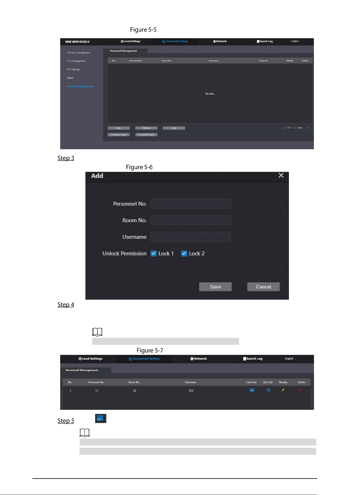
27
Personnel management
Click Add.
Add personnel information
Enter the parameters, and then click Save.
Lock1: Local lock.
Lock 2: 485 lock.
Only models that have 485 ports support 2 types of locks.
Operation succeed
Click to go to the card issuing window.
For some VTO models, the QR code is embedded in the Personnel Management page. Yet
for some models, you need to go to Network > Basic > Cloud Service to check the QR code.
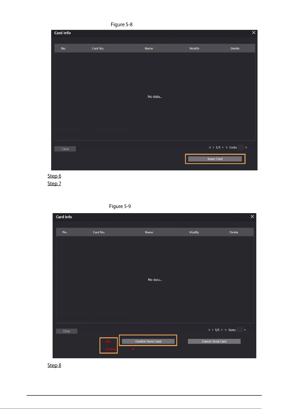
28
Card issuing window
Click Issue Card to issue cards.
The web page displays the countdown prompt (120 s). Once the countdown starts, you need
to swipe the card on the card reader of the VTO within this time period. After the swiping, the
card number will be automatically recognized by the VTO.
Countdown in process
Click Confirm Send Card after swiping to complete the issuing process.

29
Newly issued Cards
Other Operations
Click to set it to loss, and then the icon changes to . The lost card cannot be used to open
the door.
Click or to modify the username or delete the card.
VTS Management
You can add a VTS to the SIP server, and then it can be used as the management center. It can also
manage, call, or receive calls from all the VTOs and VTHs in the network. See the corresponding user's
manual for details.
Log in to the web page of the VTO that works as the SIP server.
Select Household Setting > VTS Settings.
VTS management
Click Add.
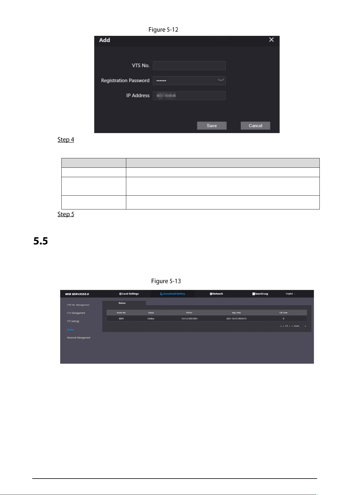
30
Add VTS
Configure the parameters.
Table 5-3 Add VTS configuration
Parameter Description
VTS No. The number of the VTS.
Registeration
Password
Leave it as default.
IP Address VTS IP address.
Click Save.
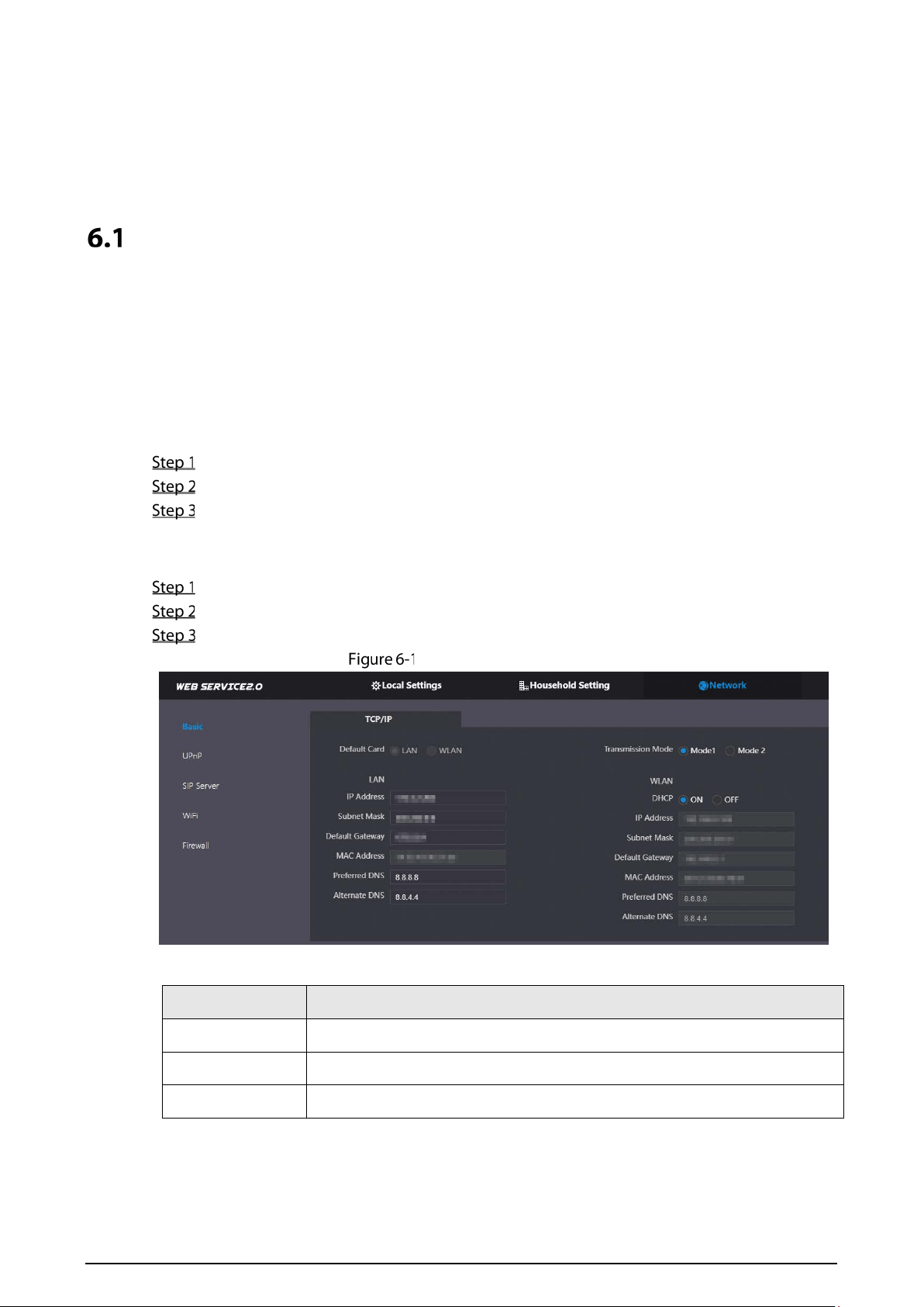
Status
You can view the online status and IP addresses of all the connected devices.
Log in to the web home page of the SIP server, and then select Household Setting > Status.
Status
31
6 Network
This chapter introduces how to configure the network parameters.
Basic
6.1.1 TCP/IP
You need to configure the TCP/IP information to connect the VTO to the network. The descriptions
below are for models with a Wireless LAN card. A Wireless LAN device is optional.
Wireless LAN
Log in to the web page of the VTO.
Select Network > Basic.
Configure the TCP/IP parameters in the WLAN section.
LAN
Log in to the web page of the VTO.
Select Network > Basic.
Configure the TCP/IP parameters in the LAN section.
Network configuration
Table 6-1 Parameter description
Parameter Description
IP Address Your planned IP address for the VTO.
Preferred DNS It is 8.8.8.8 by default.
Alternate DNS It is 8.8.4.4 by default.
32
Parameter Description
Transmission
Mode
Choose the transmission mode based on your actual needs.
Mode 1: Multicast streaming (UDP).
Mode 2: RTSP streaming (TCP).
Mode 2 is preferred when the switch does not support multicast
function, or when the network connection is not good.
DHCP Enable the function to get the allocated IP address for the VTO.
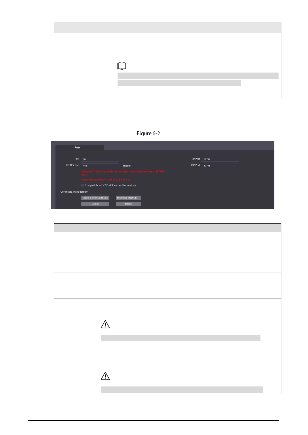
6.1.2 Port
Port
Table 6-2 Parameter description
Parameter Description
Port
80 by default.
If already used, choose any number from 1025 to 65535 as
needed. You can enter http://VTO IP address: Port to log in to the VTO.
HTTPS Port
Enable it and click Save. You can now enter https://VTO IP address: HTTPS Port to
log in to the VTO.
TCP/UDP Port
Used for accessing the VTO with devices in other networks. See "6.2 UPnP" for
details.
Create Server
Certificate
The unique digital identification of VTO for the SSL protocol. For first time use or
after changing the IP address of the VTO, you need to go through this process.
If you delete the certificate that has been created, it cannot be undone.
Download Root
CERT
If you are using a PC that has never logged in to the VTO, you need to download
the root certificate, double-click to install it, and then you can use the HTTPS
function mentioned above.
If you delete the certificate that has been installed, it cannot be undone.

33
6.1.3 Cloud service
Cloud service
Enable the Cloud Service function, and then you can scan the QR code with your phone to add the
VTO to the app on your smartphone.
For some VTO models, the QR code is embedded in the Cloud Service module. Yet for some models,
you need to go to Household Setting > Personnel Management to check the QR code.
UPnP
When the VTO works as the SIP server, you can configure the UPnP function to allow WAN devices to
log in to the VTO.
UPnP
Preparation
Enable the UPnP function on the router, and then configure a WAN IP address for the router.
Connect the VTO to the LAN port of the router.
6.2.2 Enabling UPnP Services
Select Network > UPnP.

34
Enable the services listed.
Select Enable.
Click Save.
6.2.3 Adding UPnP Services
Select Network > UPnP.
Click Add.
Configure the parameters as needed.
Add a UPnP service
Table 6-3 Parameter description
Parameter Description
Service Name
Enter the information as needed.
Service Type
Protocol Select TCP or UDP.
Internal Port Use port number from 1024 through 5000.
Do not use port number 1–1023 to avoid conflict.
If you need to configure this function for multiple devices, make sure that
the ports are not the same.
The port number you use must not be occupied.
The internal and external port number must be the same.
External Port
SIP Server
There must be a SIP server in the network for all connected VTOs and VTHs to call each other. You can
use a VTO or other servers as the SIP server.
Select Network > SIP Server.
Select a server type.

35
The VTO you have logged in as the SIP server:
Enable SIP Server, and click Save. You can add VTOs and VTHs to this VTO. See the details
in "5 Household Setting".
If the VTO you have logged in does not work as the SIP server, do not enable SIP Server;
otherwise the connection will fail.
If another VTO works as the SIP server:
Do not enable SIP server. Set Server Type to VTO, configure the parameters, and then
click Save.
VTO as the SIP server
Table 6-4 SIP server configuration (VTO as the SIP server)
Parameter Description
IP Addr. Your planned IP address of the VTO.
Port 5060 by default when a VTO works as the SIP server.
Username
Leave it as default.
Password
SIP Domain Leave it as default.
SIP Server Username
Username and password used to log into the web page of the SIP server.
SIP Server Password
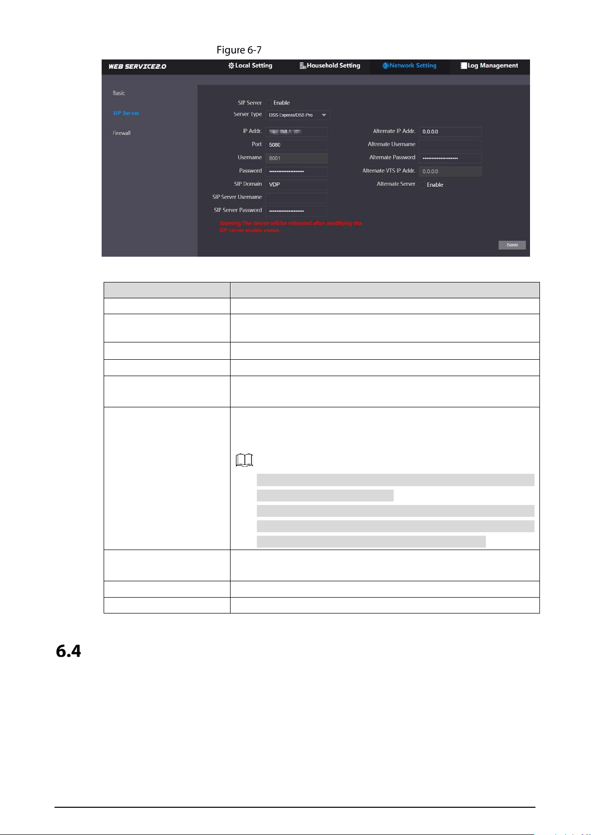
If the platform works as the SIP server:
Set Server Type as DSS Express/DSS Pro, and configure the parameters, and then
enable the SIP Server.
36
Platform as the SIP server
Table 6-5 SIP server description (platform as the SIP server)
Parameter Description
IP Addr. IP address of the SIP server.
Port 5080 by default when the platform works as the SIP server.
Username/Password Leave it as default.
SIP Domain Leave it as default.
SIP Server Username/
Password
Used to log in to the SIP server.
Alternate IP Addr.
The alternate server will be used as the SIP server when Express/DSS
stops responding. We recommend you configure the alternate IP
address.
If you enable Alternate Server, the current VTO you have logged
in serves as the alternate server.
If you want another VTO serve as the alternate server, you need
to enter the IP address of that VTO in the Alternate IP Addr.
textbox. Do not enable Alternate Server in this case.
Alternate Username/
Password
Used to log in to the alternate server.
Alternate VTS IP Addr. IP address of the alternate VTS.
Alternate Server Enable it as needed.
Wi-Fi
If the VTO supports Wi-Fi function, then configure the parameters here.

37
Wi-Fi
Select Network > WiFi.
Set the WiFi status as On.
Select a region, and all the networks available in this region are displayed.
Click to connect to the network that you chose.
Firewall
You can enable different firewall types to control network access to the VTO.
Select Network > Firewall.
Firewall
Select Type, and then enable it.
Configure the parameters.
Click Confirm.
Table 6-6 Firewall type description
Type Description
Network Access
Select either Allowlist or Blocklist, and then add an IP address or segment
which is allowed or denied to access the VTO.
PING Prohibited The VTO will not response to ping to avoid ping attacks.
Anti-semijoin Protects the VTO performance by blocking excessive SYN packets.
Mode
Allowlist: Devices that have been granted an access.
Blocklist: Devices that have been forbidden an access.
38
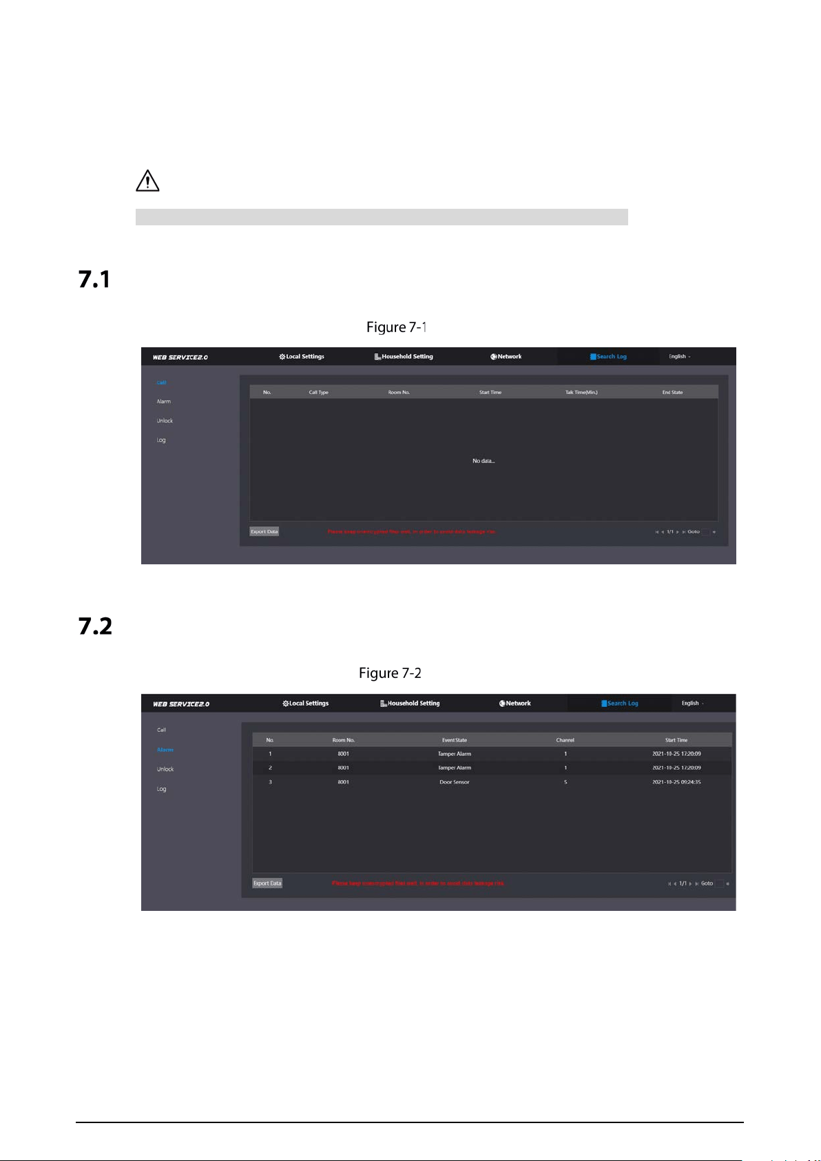
7 Log Management
Select Search Log. You can search for different logs, and export them to your PC as needed.
If storage is full, the oldest records will be overwritten. Back up the records in time.
Call
Call
Alarm
Alarm

39
Unlock
Unlock
Log
Select time range and type, and then you can see all the log information.
Log
40
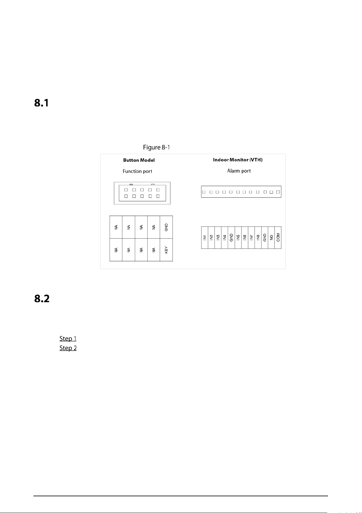
8 Button Model Configuration
The button model can be connected to the VTH to work as an alarm input button. Press the button on
the front panel of the model, and then the VTH receives an alarm signal.
Cable Connection
Connect the KEY port of the button model to any one of the alarm input ports of the indoor monitor
(VTH) with a cable thread.
Cable connection
VTH Configuration
After completing cable connection, you need to set the wired zone type as Doorbell on the VTH to
receive alarm signals once you press the button model.
Power on the VTH.
Tap Setting > Alarm > Wired Zone on the VTH.

41
Wired zone setting
Set the Type as Doorbell, and configure the rest of the parameters.
Tap OK to complete setting.
Table 8-1 Parameter description
Parameter
Description
Area The number cannot be modified.
NO/NC
Select NO (normally open) or NC (normally closed) according to detector type. It must
be the same as detector type.
Type
Select corresponding type according to detector type, including IR, gas, smoke,
urgency btn, door, burglar alarm, perimeter and doorbell.
Status
Instant Alarm: After armed, if an alarm is triggered, the device produces siren at
once and enters alarm status.
Delay Alarm: After armed, if an alarm is triggered, the device enters alarm status
after a specified time, during which you can disarm and cancel the alarm.
Bypass: Alarm will not be triggered in the area. After disarmed, this area will
restore to normal working status.
Remove: The area is invalid during arm/disarm.
24 Hour: Alarm will be triggered all the time in the area regardless of arm or
disarm.
A zone in Remove status cannot be bypassed.
Enter Delay
After entering delay, when armed area triggers an alarm,
entering armed area from non-armed area within the delay
time period will not lead to linkage alarm. Linkage alarm will
be produced if delay time comes to an end and it is not
disarmed.
Delay is only valid to
the areas of Delay
Alarm.
Exit Delay
After arm, Delay Alarm area will enter arm status at the end
of Exit Delay.
If multiple areas set the exit delay, screen prompt will conform
to maximum delay time.

42
Cybersecurity Recommendations
Mandatory actions to be taken for basic device network security:
1. Use Strong Passwords
Please refer to the following suggestions to set passwords:
The length should not be less than 8 characters;
Include at least two types of characters; character types include upper and lower case
letters, numbers and symbols;
Do not contain the account name or the account name in reverse order;
Do not use continuous characters, such as 123, abc, etc.;
Do not use overlapped characters, such as 111, aaa, etc.;
2. Update Firmware and Client Software in Time
According to the standard procedure in Tech-industry, we recommend to keep your device
(such as NVR, DVR, IP camera, etc.) firmware up-to-date to ensure the system is equipped
with the latest security patches and fixes. When the device is connected to the public
network, we recommend enabling the "auto-check for updates" function to obtain timely
information of firmware updates released by the manufacturer.
We suggest that you download and use the latest version of client software.
"Nice to have" recommendations to improve your device network security:
1. Physical Protection
We suggest that you perform physical protection to device, especially storage devices. For
example, place the device in a special computer room and cabinet, and implement well-done
access control permission and key management to prevent unauthorized personnel from
carrying out physical contacts such as damaging hardware, unauthorized connection of
removable device (such as USB flash disk, serial port), etc.
2. Change Passwords Regularly
We suggest that you change passwords regularly to reduce the risk of being guessed or cracked.
3. Set and Update Passwords Reset Information Timely
The device supports password reset function. Please set up related information for password
reset in time, including the end user’s mailbox and password protection questions. If the
information changes, please modify it in time. When setting password protection questions, it is
suggested not to use those that can be easily guessed.
4. Enable Account Lock
The account lock feature is enabled by default, and we recommend you to keep it on to guarantee
the account security. If an attacker attempts to log in with the wrong password several times, the
corresponding account and the source IP address will be locked.
5. Change Default HTTP and Other Service Ports
We suggest you to change default HTTP and other service ports into any set of numbers between
1024~65535, reducing the risk of outsiders being able to guess which ports you are using.
6. Enable HTTPS
We suggest you to enable HTTPS, so that you visit Web service through a secure communication
channel.
7. MAC Address Binding
We recommend you to bind the IP and MAC address of the gateway to the device, thus reducing
the risk of ARP spoofing.

43
8. Assign Accounts and Privileges Reasonably
According to business and management requirements, reasonably add users and assign a
minimum set of permissions to them.
9. Disable Unnecessary Services and Choose Secure Modes
If not needed, we recommend turning off some services such as SNMP, SMTP, UPnP, etc., to reduce
risks.
If necessary, it is highly recommended that you use safe modes, including but not limited to the
following services:
SNMP: Choose SNMP v3, and set up strong encryption passwords and authentication
passwords.
SMTP: Choose TLS to access mailbox server.
FTP: Choose SFTP, and set up strong passwords.
AP hotspot: Choose WPA2-PSK encryption mode, and set up strong passwords.
10. Audio and Video Encrypted Transmission
If your audio and video data contents are very important or sensitive, we recommend that you
use encrypted transmission function, to reduce the risk of audio and video data being stolen
during transmission.
Reminder: encrypted transmission will cause some loss in transmission efficiency.
11. Secure Auditing
Check online users: we suggest that you check online users regularly to see if the device is
logged in without authorization.
Check device log: By viewing the logs, you can know the IP addresses that were used to log
in to your devices and their key operations.
12. Network Log
Due to the limited storage capacity of the device, the stored log is limited. If you need to save the
log for a long time, it is recommended that you enable the network log function to ensure that
the critical logs are synchronized to the network log server for tracing.
13. Construct a Safe Network Environment
In order to better ensure the safety of device and reduce potential cyber risks, we recommend:
Disable the port mapping function of the router to avoid direct access to the intranet devices
from external network.
The network should be partitioned and isolated according to the actual network needs. If
there are no communication requirements between two sub networks, it is suggested to use
VLAN, network GAP and other technologies to partition the network, so as to achieve the
network isolation effect.
Establish the 802.1x access authentication system to reduce the risk of unauthorized access
to private networks.
Enable IP/MAC address filtering function to limit the range of hosts allowed to access the
device.