
Avid VENUE | S6L System Guide
and Avid VENUE | Software 6.1

Legal Notices
© 2019 Avid Technology, Inc., (“Avid”), all rights reserved. This guide may not be duplicated in whole or in part without the written consent of Avid.
For a current and complete list of Avid trademarks visit:
http://www.avid.com/legal/trademarks-and-other-notices
Bonjour, the Bonjour logo, and the Bonjour symbol are trademarks of Apple Computer, Inc.
Thunderbolt and the Thunderbolt logo are trademarks of Intel Corporation in the U.S. and/or other countries.
This product may be protected by one or more U.S. and non-U.S. patents. Details are available at
www.avid.com/patents.
Product features, specifications, system requirements, and availability are subject to change without notice.
Guide Part Number 9329-66014-00 REV A 02/19

Safety Compliance
Safety Statement: (M/N: S6L16, S6L24(all), S6L32, Local 16, Stage 16, Stage 32 and Stage 64)
This equipment has been tested to comply with USA and Canadian safety certification in accordance with the specifications of UL Standards: UL 60065 7th Ed.,
2013-07-24, CAN/CSA C22.2 No. 60065-03, 1st Ed, +A1:2006 +A2:2012, EN 60065:2002 +A1:2006 +A11:2008 +A2:2010 +A12:2011, IEC 60065:2001 +A1:2005
+A2:2010.
Avid Technology Inc., has been authorized to apply the appropriate NRTL mark on its compliant equipment.
Safety Statement: (M/N: E6L(all))
This equipment has been tested to comply with USA and Canadian safety certification in accordance with the specifications of UL Standards: UL 60950-1 2nd edition,
CAN/CSA C22.2 No. 60950-1-07; 2nd edition, EN 60950-1:2006 /A12:2011, IEC 60950-1:2005+ A1:2009 2nd edition.
Avid Technology Inc., has been authorized to apply the appropriate NRTL mark on its compliant equipment.
Power Safety Input Rating
S6L16: AC~100-240V, 50-60Hz, 4.0A per inlet
S6L24(all): AC~100-240V, 50-60Hz, 4.0A per inlet
S6L32: AC~100-240V, 50-60Hz, 5.0A per inlet
E6L(all): AC~100-240V, 50-60Hz, 5.0A per inlet
Local 16: AC~100-240V, 50-60Hz, 0.6A per inlet
Stage 16: AC~100-240V, 50-60Hz, 0.6A
Stage 32: AC~100-240V, 50-60Hz, 3.65A per inlet
Stage 64: AC~100-240V, 50-60Hz, 3.65A per inlet
Warning
Important Safety Instructions for E6L
1) User should make sure that all the thumb screws are secured by a tool.
2) The E6L system can hold the following cards:
• (3) AVB Cards
• (4) HDX Cards
• (4) MADI-192 MADI Option Cards
• (8) DIMMs of RAM.
User should not install additional cards.
Important Safety Instructions
1) Read these instructions.
2) Keep these instructions.
3) Heed all warnings.
4) Follow all instructions.
5) Do not use this equipment near water.
6) Clean only with dry cloth.
7) Do not block any ventilation openings. Install in accordance with the manufacturer's instructions.
8) Do not install near any heat sources such as radiators, heat registers, stoves, or other equipment (including amplifiers) that produce heat.
10) Protect power cords from being walked on or pinched particularly at plugs, convenience receptacles, and the point where they exit from the equipment.
11) Only use attachments/accessories specified by the manufacturer.
12) For products that are not rack-mountable: Use only with a cart, stand, tripod, bracket, or table specified by the manufacturer, or sold with the equipment. When a cart
is used, use caution when moving the cart/equipment combination to avoid injury from tip-over.
13) Unplug this equipment during lightning storms or when unused for long periods of time.
14) Refer all servicing to qualified service personnel. Servicing is required when the equipment has been damaged in any way, such as power-supply cord or plug is dam-
aged, liquid has been spilled or objects have fallen into the equipment, the equipment has been exposed to rain or moisture, does not operate normally, or has been
dropped.
15) For products that are a Mains powered device:
The equipment shall not be exposed to dripping or splashing and no objects filled with liquids (such as vases) shall be placed on the equipment.
Warning! To reduce the risk of fire or electric shock, do not expose this equipment to rain or moisture.
Do not defeat the safety purpose of the polarized or grounding-type plug. A polarized plug has two blades with one wider than the other. A grounding type plug
has two blades and a third grounding prong. The wide blade or the third prong are provided for your safety. If the provided plug does not fit into your outlet, consult
an electrician for replacement of the obsolete outlet.
16) For products containing a lithium battery:
Warning! Danger of explosion if battery is incorrectly replaced. Replace only with the same or equivalent type.
17) For products with a power switch:
It should remain accessible after installation.
18) The equipment shall be used at a maximum ambient temperature of 40° C and maximum altitude of 2000m.
19) This unit may not ship with a power supply cord set. A qualified person must provide for use with this unit, an appropriate, approved power supply cord set which is in
compliance with the end use country requirements and has a minimum cross-sectional area of 1.0mm
2
.
20) For products with more than one power cord:
CAUTION: This unit has more than one power supply cord. Disconnect two power supply cords before servicing to avoid electrical shock.
ATTENTION: Cet appareil comporte plus d'un cordon d'alimentation. Afin de prévenir les chocs électriques, débrancher les deux cordons d'alimentation avant de faire le
dépannage.
21) For products with an operator-accessible fuse:
CAUTION: For continued protection against risk of fire, replace only with same type and rating of fuse.
ATTENTION: Pour ne pas compromettre la protection contre les risques d'incendie, remplacer par un fusible de même type et de même caractéristiques nominales.
22) For products with Fiber optics:
Warning! Fiber optic equipment can emit laser or infrared light that can injure your eyes. Never look into an optical fiber or connector port.
Always assume that fiber optic cables are connected to a light source.

VENUE | S6L System Guide v
Part I Overview
Introduction to the VENUE | S6L System. . . . . . . . . . . . . . . . . . . . . . . . . . . . . . . . . . . . . . . . . . . . . . . . . . . . . . . . . . . . 1
Installation and Setup . . . . . . . . . . . . . . . . . . . . . . . . . . . . . . . . . . . . . . . . . . . . . . . . . . . . . . . . . . . . . . . . . . . . . . . . 1
S6L System Features . . . . . . . . . . . . . . . . . . . . . . . . . . . . . . . . . . . . . . . . . . . . . . . . . . . . . . . . . . . . . . . . . . . . . . . . . 1
S6L Control Surface Features . . . . . . . . . . . . . . . . . . . . . . . . . . . . . . . . . . . . . . . . . . . . . . . . . . . . . . . . . . . . . . . . . . 2
E6L Engine Features . . . . . . . . . . . . . . . . . . . . . . . . . . . . . . . . . . . . . . . . . . . . . . . . . . . . . . . . . . . . . . . . . . . . . . . . . 5
Stage 64 I/O Rack Features . . . . . . . . . . . . . . . . . . . . . . . . . . . . . . . . . . . . . . . . . . . . . . . . . . . . . . . . . . . . . . . . . . . . 6
Stage 32 I/O Rack Features . . . . . . . . . . . . . . . . . . . . . . . . . . . . . . . . . . . . . . . . . . . . . . . . . . . . . . . . . . . . . . . . . . . . 7
Stage 16 Remote IO Features . . . . . . . . . . . . . . . . . . . . . . . . . . . . . . . . . . . . . . . . . . . . . . . . . . . . . . . . . . . . . . . . . . 8
Local 16 I/O Features . . . . . . . . . . . . . . . . . . . . . . . . . . . . . . . . . . . . . . . . . . . . . . . . . . . . . . . . . . . . . . . . . . . . . . . . . 9
What’s Included . . . . . . . . . . . . . . . . . . . . . . . . . . . . . . . . . . . . . . . . . . . . . . . . . . . . . . . . . . . . . . . . . . . . . . . . . . . . . 9
Expansion Options. . . . . . . . . . . . . . . . . . . . . . . . . . . . . . . . . . . . . . . . . . . . . . . . . . . . . . . . . . . . . . . . . . . . . . . . . . 10
Operational Requirements . . . . . . . . . . . . . . . . . . . . . . . . . . . . . . . . . . . . . . . . . . . . . . . . . . . . . . . . . . . . . . . . . . . . 11
Cabling Requirements . . . . . . . . . . . . . . . . . . . . . . . . . . . . . . . . . . . . . . . . . . . . . . . . . . . . . . . . . . . . . . . . . . . . . . . 12
System Requirements and Compatibility . . . . . . . . . . . . . . . . . . . . . . . . . . . . . . . . . . . . . . . . . . . . . . . . . . . . . . . . 12
Resources. . . . . . . . . . . . . . . . . . . . . . . . . . . . . . . . . . . . . . . . . . . . . . . . . . . . . . . . . . . . . . . . . . . . . . . . . . . . . . . . . 13
Activation . . . . . . . . . . . . . . . . . . . . . . . . . . . . . . . . . . . . . . . . . . . . . . . . . . . . . . . . . . . . . . . . . . . . . . . . . . . . . . . . . 13
Conventions Used in This Guide. . . . . . . . . . . . . . . . . . . . . . . . . . . . . . . . . . . . . . . . . . . . . . . . . . . . . . . . . . . . . . . 14
S6L Control Surface Overview . . . . . . . . . . . . . . . . . . . . . . . . . . . . . . . . . . . . . . . . . . . . . . . . . . . . . . . . . . . . . . . . . . . . 15
S6L Control Surface Top Panel Overview. . . . . . . . . . . . . . . . . . . . . . . . . . . . . . . . . . . . . . . . . . . . . . . . . . . . . . . . 15
Fader Banks . . . . . . . . . . . . . . . . . . . . . . . . . . . . . . . . . . . . . . . . . . . . . . . . . . . . . . . . . . . . . . . . . . . . . . . . . . . . . . . 16
Channel Knob Modules (CKM). . . . . . . . . . . . . . . . . . . . . . . . . . . . . . . . . . . . . . . . . . . . . . . . . . . . . . . . . . . . . . . . . 21
Channel Touch Module (CTM) . . . . . . . . . . . . . . . . . . . . . . . . . . . . . . . . . . . . . . . . . . . . . . . . . . . . . . . . . . . . . . . . . 26
Master Live Module (MLM) . . . . . . . . . . . . . . . . . . . . . . . . . . . . . . . . . . . . . . . . . . . . . . . . . . . . . . . . . . . . . . . . . . . . 28
Master Touch Screen (MTS). . . . . . . . . . . . . . . . . . . . . . . . . . . . . . . . . . . . . . . . . . . . . . . . . . . . . . . . . . . . . . . . . . . 37
S6L Control Surface Connections . . . . . . . . . . . . . . . . . . . . . . . . . . . . . . . . . . . . . . . . . . . . . . . . . . . . . . . . . . . . . . 42
E6L Engine Overview . . . . . . . . . . . . . . . . . . . . . . . . . . . . . . . . . . . . . . . . . . . . . . . . . . . . . . . . . . . . . . . . . . . . . . . . . . . . 46
E6L Cards and Features. . . . . . . . . . . . . . . . . . . . . . . . . . . . . . . . . . . . . . . . . . . . . . . . . . . . . . . . . . . . . . . . . . . . . . 46
E6L Front Panel . . . . . . . . . . . . . . . . . . . . . . . . . . . . . . . . . . . . . . . . . . . . . . . . . . . . . . . . . . . . . . . . . . . . . . . . . . . . 47
E6L Back Panel. . . . . . . . . . . . . . . . . . . . . . . . . . . . . . . . . . . . . . . . . . . . . . . . . . . . . . . . . . . . . . . . . . . . . . . . . . . . . 48
Stage and Local I/O Rack Overview . . . . . . . . . . . . . . . . . . . . . . . . . . . . . . . . . . . . . . . . . . . . . . . . . . . . . . . . . . . . . . . 50
Stage 64 and Stage 32 I/O Card Features and Capabilities . . . . . . . . . . . . . . . . . . . . . . . . . . . . . . . . . . . . . . . . . . 51
Stage 64 Front Panel . . . . . . . . . . . . . . . . . . . . . . . . . . . . . . . . . . . . . . . . . . . . . . . . . . . . . . . . . . . . . . . . . . . . . . . . 52
Making Stage I/O Unit Connections. . . . . . . . . . . . . . . . . . . . . . . . . . . . . . . . . . . . . . . . . . . . . . . . . . . . . . . . . . . . . 54
Stage 64 Controller Display . . . . . . . . . . . . . . . . . . . . . . . . . . . . . . . . . . . . . . . . . . . . . . . . . . . . . . . . . . . . . . . . . . . 54
Using MADI Outs on Stage 64 and Stage 32 . . . . . . . . . . . . . . . . . . . . . . . . . . . . . . . . . . . . . . . . . . . . . . . . . . . . . . 59
Contents

VENUE | S6L System Guide vi
Part II Using S6L
Configuring System Audio . . . . . . . . . . . . . . . . . . . . . . . . . . . . . . . . . . . . . . . . . . . . . . . . . . . . . . . . . . . . . . . . . . . . . . . 61
Powering the System Up and Down . . . . . . . . . . . . . . . . . . . . . . . . . . . . . . . . . . . . . . . . . . . . . . . . . . . . . . . . . . . . 62
Confirming System Components . . . . . . . . . . . . . . . . . . . . . . . . . . . . . . . . . . . . . . . . . . . . . . . . . . . . . . . . . . . . . . 64
Pairing the E6L and S6L. . . . . . . . . . . . . . . . . . . . . . . . . . . . . . . . . . . . . . . . . . . . . . . . . . . . . . . . . . . . . . . . . . . . . . 65
Enabling Config Mode . . . . . . . . . . . . . . . . . . . . . . . . . . . . . . . . . . . . . . . . . . . . . . . . . . . . . . . . . . . . . . . . . . . . . . . 67
Assigning Stage I/O Units . . . . . . . . . . . . . . . . . . . . . . . . . . . . . . . . . . . . . . . . . . . . . . . . . . . . . . . . . . . . . . . . . . . . 68
Assigning Local 16. . . . . . . . . . . . . . . . . . . . . . . . . . . . . . . . . . . . . . . . . . . . . . . . . . . . . . . . . . . . . . . . . . . . . . . . . . 71
Setting the System Clock. . . . . . . . . . . . . . . . . . . . . . . . . . . . . . . . . . . . . . . . . . . . . . . . . . . . . . . . . . . . . . . . . . . . . 76
Configuring Mains and Mix Buses. . . . . . . . . . . . . . . . . . . . . . . . . . . . . . . . . . . . . . . . . . . . . . . . . . . . . . . . . . . . . . 77
Managing Connections . . . . . . . . . . . . . . . . . . . . . . . . . . . . . . . . . . . . . . . . . . . . . . . . . . . . . . . . . . . . . . . . . . . . . . 79
How to Proceed . . . . . . . . . . . . . . . . . . . . . . . . . . . . . . . . . . . . . . . . . . . . . . . . . . . . . . . . . . . . . . . . . . . . . . . . . . . . 83
Banking Channels on the S6L Control Surface . . . . . . . . . . . . . . . . . . . . . . . . . . . . . . . . . . . . . . . . . . . . . . . . . . . . . 84
Channel Banking Overview . . . . . . . . . . . . . . . . . . . . . . . . . . . . . . . . . . . . . . . . . . . . . . . . . . . . . . . . . . . . . . . . . . . 84
Banking a Combination of Inputs and Outputs . . . . . . . . . . . . . . . . . . . . . . . . . . . . . . . . . . . . . . . . . . . . . . . . . . . 85
Banking Only User Layouts, VCAs, Inputs, or Outputs . . . . . . . . . . . . . . . . . . . . . . . . . . . . . . . . . . . . . . . . . . . . . 88
Spill Mode for Outputs . . . . . . . . . . . . . . . . . . . . . . . . . . . . . . . . . . . . . . . . . . . . . . . . . . . . . . . . . . . . . . . . . . . . . . . 89
User Layouts . . . . . . . . . . . . . . . . . . . . . . . . . . . . . . . . . . . . . . . . . . . . . . . . . . . . . . . . . . . . . . . . . . . . . . . . . . . . . . 90
Bank Safing Channels . . . . . . . . . . . . . . . . . . . . . . . . . . . . . . . . . . . . . . . . . . . . . . . . . . . . . . . . . . . . . . . . . . . . . . . 97
Selecting and Attentioning Channels . . . . . . . . . . . . . . . . . . . . . . . . . . . . . . . . . . . . . . . . . . . . . . . . . . . . . . . . . . . . . 100
Selecting Channels . . . . . . . . . . . . . . . . . . . . . . . . . . . . . . . . . . . . . . . . . . . . . . . . . . . . . . . . . . . . . . . . . . . . . . . . 100
Attentioning Channels . . . . . . . . . . . . . . . . . . . . . . . . . . . . . . . . . . . . . . . . . . . . . . . . . . . . . . . . . . . . . . . . . . . . . . 102
Attention on Fader . . . . . . . . . . . . . . . . . . . . . . . . . . . . . . . . . . . . . . . . . . . . . . . . . . . . . . . . . . . . . . . . . . . . . . . . . 103
Selecting/Attentioning Multiple Channels (Multi-Select) . . . . . . . . . . . . . . . . . . . . . . . . . . . . . . . . . . . . . . . . . . . 104
Adjusting Channel Parameters. . . . . . . . . . . . . . . . . . . . . . . . . . . . . . . . . . . . . . . . . . . . . . . . . . . . . . . . . . . . . . . . . . . 106
Configuring and Patching Channels . . . . . . . . . . . . . . . . . . . . . . . . . . . . . . . . . . . . . . . . . . . . . . . . . . . . . . . . . . . 106
Assigning Channels to Outputs . . . . . . . . . . . . . . . . . . . . . . . . . . . . . . . . . . . . . . . . . . . . . . . . . . . . . . . . . . . . . . 107
Assign VCAs and Mute Groups from Channel Control Encoders . . . . . . . . . . . . . . . . . . . . . . . . . . . . . . . . . . . . 109
Adjusting Input Parameters on the Control Surface. . . . . . . . . . . . . . . . . . . . . . . . . . . . . . . . . . . . . . . . . . . . . . . 110
Adjusting EQ on the Control Surface . . . . . . . . . . . . . . . . . . . . . . . . . . . . . . . . . . . . . . . . . . . . . . . . . . . . . . . . . . 118
Adjusting Dynamics on the Control Surface. . . . . . . . . . . . . . . . . . . . . . . . . . . . . . . . . . . . . . . . . . . . . . . . . . . . . 122
Adjusting Plug-Ins on the Control Surface . . . . . . . . . . . . . . . . . . . . . . . . . . . . . . . . . . . . . . . . . . . . . . . . . . . . . . 125
Using the CHANNEL Function. . . . . . . . . . . . . . . . . . . . . . . . . . . . . . . . . . . . . . . . . . . . . . . . . . . . . . . . . . . . . . . . 127
Flipping Parameters to Faders (Flip to Faders Mode) . . . . . . . . . . . . . . . . . . . . . . . . . . . . . . . . . . . . . . . . . . . . . 128
Encoder Assign Mode . . . . . . . . . . . . . . . . . . . . . . . . . . . . . . . . . . . . . . . . . . . . . . . . . . . . . . . . . . . . . . . . . . . . . . 129
Working with Mains and VCAs . . . . . . . . . . . . . . . . . . . . . . . . . . . . . . . . . . . . . . . . . . . . . . . . . . . . . . . . . . . . . . . . . . . 130
Working with Mains . . . . . . . . . . . . . . . . . . . . . . . . . . . . . . . . . . . . . . . . . . . . . . . . . . . . . . . . . . . . . . . . . . . . . . . . 130
Working with VCAs . . . . . . . . . . . . . . . . . . . . . . . . . . . . . . . . . . . . . . . . . . . . . . . . . . . . . . . . . . . . . . . . . . . . . . . . 134
Working with Aux Sends . . . . . . . . . . . . . . . . . . . . . . . . . . . . . . . . . . . . . . . . . . . . . . . . . . . . . . . . . . . . . . . . . . . . . . . . 137
Adjusting Aux Sends in Channel Control Mode . . . . . . . . . . . . . . . . . . . . . . . . . . . . . . . . . . . . . . . . . . . . . . . . . . 137
Adjusting Aux Sends in Channel Strip Mode . . . . . . . . . . . . . . . . . . . . . . . . . . . . . . . . . . . . . . . . . . . . . . . . . . . . 140
Adjusting Aux Sends on Faders (Sends on Faders Mode) . . . . . . . . . . . . . . . . . . . . . . . . . . . . . . . . . . . . . . . . . 141

VENUE | S6L System Guide vii
VCAs Trim Aux Sends in Sends on Faders Mode. . . . . . . . . . . . . . . . . . . . . . . . . . . . . . . . . . . . . . . . . . . . . . . . . 144
Adjusting Aux Sends on the External Screen. . . . . . . . . . . . . . . . . . . . . . . . . . . . . . . . . . . . . . . . . . . . . . . . . . . . 145
Classifying Auxes for Snapshots . . . . . . . . . . . . . . . . . . . . . . . . . . . . . . . . . . . . . . . . . . . . . . . . . . . . . . . . . . . . . 146
Matrix Mixers . . . . . . . . . . . . . . . . . . . . . . . . . . . . . . . . . . . . . . . . . . . . . . . . . . . . . . . . . . . . . . . . . . . . . . . . . . . . . . . . . . . 147
Matrix Mixers Overview . . . . . . . . . . . . . . . . . . . . . . . . . . . . . . . . . . . . . . . . . . . . . . . . . . . . . . . . . . . . . . . . . . . . . 147
Assigning Input Sources to Matrix Mixers . . . . . . . . . . . . . . . . . . . . . . . . . . . . . . . . . . . . . . . . . . . . . . . . . . . . . . 148
Adjusting Matrix Mixer Input Controls . . . . . . . . . . . . . . . . . . . . . . . . . . . . . . . . . . . . . . . . . . . . . . . . . . . . . . . . . 149
Delay Compensation with Matrix Mixers . . . . . . . . . . . . . . . . . . . . . . . . . . . . . . . . . . . . . . . . . . . . . . . . . . . . . . . . 152
Adjusting Matrix Mixer Output Controls . . . . . . . . . . . . . . . . . . . . . . . . . . . . . . . . . . . . . . . . . . . . . . . . . . . . . . . . 152
Snapshot Data and Parameters for Matrix Mixers . . . . . . . . . . . . . . . . . . . . . . . . . . . . . . . . . . . . . . . . . . . . . . . . 153
Muting and Mute Groups . . . . . . . . . . . . . . . . . . . . . . . . . . . . . . . . . . . . . . . . . . . . . . . . . . . . . . . . . . . . . . . . . . . . . . . . 154
Muting Individual Channels . . . . . . . . . . . . . . . . . . . . . . . . . . . . . . . . . . . . . . . . . . . . . . . . . . . . . . . . . . . . . . . . . . 154
Mute Groups . . . . . . . . . . . . . . . . . . . . . . . . . . . . . . . . . . . . . . . . . . . . . . . . . . . . . . . . . . . . . . . . . . . . . . . . . . . . . . 156
Snapshot Data and Parameters for Mute . . . . . . . . . . . . . . . . . . . . . . . . . . . . . . . . . . . . . . . . . . . . . . . . . . . . . . . 161
Soloing and the Monitor Buses . . . . . . . . . . . . . . . . . . . . . . . . . . . . . . . . . . . . . . . . . . . . . . . . . . . . . . . . . . . . . . . . . . 162
Configuring the Monitor Buses and Solo Options . . . . . . . . . . . . . . . . . . . . . . . . . . . . . . . . . . . . . . . . . . . . . . . . 162
Adjusting Monitor Buses . . . . . . . . . . . . . . . . . . . . . . . . . . . . . . . . . . . . . . . . . . . . . . . . . . . . . . . . . . . . . . . . . . . . 164
Soloing Channels . . . . . . . . . . . . . . . . . . . . . . . . . . . . . . . . . . . . . . . . . . . . . . . . . . . . . . . . . . . . . . . . . . . . . . . . . . 166
Using the Headphone Outputs . . . . . . . . . . . . . . . . . . . . . . . . . . . . . . . . . . . . . . . . . . . . . . . . . . . . . . . . . . . . . . . 170
Part III External VENUE Software Screen
External VENUE Software Screen Overview. . . . . . . . . . . . . . . . . . . . . . . . . . . . . . . . . . . . . . . . . . . . . . . . . . . . . . . 172
Viewing Pages and Tabs . . . . . . . . . . . . . . . . . . . . . . . . . . . . . . . . . . . . . . . . . . . . . . . . . . . . . . . . . . . . . . . . . . . . 172
Overview of Software Pages . . . . . . . . . . . . . . . . . . . . . . . . . . . . . . . . . . . . . . . . . . . . . . . . . . . . . . . . . . . . . . . . . 175
Banner Display . . . . . . . . . . . . . . . . . . . . . . . . . . . . . . . . . . . . . . . . . . . . . . . . . . . . . . . . . . . . . . . . . . . . . . . . . . . . 179
Type Text Search . . . . . . . . . . . . . . . . . . . . . . . . . . . . . . . . . . . . . . . . . . . . . . . . . . . . . . . . . . . . . . . . . . . . . . . . . . 180
Overview, Inputs, and Outputs Pages . . . . . . . . . . . . . . . . . . . . . . . . . . . . . . . . . . . . . . . . . . . . . . . . . . . . . . . . . . . . 181
Navigating the Overview, Inputs, Outputs Pages . . . . . . . . . . . . . . . . . . . . . . . . . . . . . . . . . . . . . . . . . . . . . . . . . 181
Attentioning Channels from the External Screen . . . . . . . . . . . . . . . . . . . . . . . . . . . . . . . . . . . . . . . . . . . . . . . . . 183
Adjusting Parameters on the External Screen . . . . . . . . . . . . . . . . . . . . . . . . . . . . . . . . . . . . . . . . . . . . . . . . . . . 184
Working with EQ and Dynamics on the External Screen . . . . . . . . . . . . . . . . . . . . . . . . . . . . . . . . . . . . . . . . . . . 186
Input Direct . . . . . . . . . . . . . . . . . . . . . . . . . . . . . . . . . . . . . . . . . . . . . . . . . . . . . . . . . . . . . . . . . . . . . . . . . . . . . . . 190
Copying and Pasting Settings . . . . . . . . . . . . . . . . . . . . . . . . . . . . . . . . . . . . . . . . . . . . . . . . . . . . . . . . . . . . . . . . 191
Configuring Channels on the External Screen . . . . . . . . . . . . . . . . . . . . . . . . . . . . . . . . . . . . . . . . . . . . . . . . . . . 193
Inserting Plug-Ins on Channels . . . . . . . . . . . . . . . . . . . . . . . . . . . . . . . . . . . . . . . . . . . . . . . . . . . . . . . . . . . . . . . 197
Input Channel, EQ, and Dynamics Presets . . . . . . . . . . . . . . . . . . . . . . . . . . . . . . . . . . . . . . . . . . . . . . . . . . . . . . 198
Assigning Channels to Buses and VCAs on the External Screen . . . . . . . . . . . . . . . . . . . . . . . . . . . . . . . . . . . . 200
Managing Output Channel Assignments (Members) . . . . . . . . . . . . . . . . . . . . . . . . . . . . . . . . . . . . . . . . . . . . . . 201
Color-Coding Channels from the External Screen . . . . . . . . . . . . . . . . . . . . . . . . . . . . . . . . . . . . . . . . . . . . . . . . 202
Filing . . . . . . . . . . . . . . . . . . . . . . . . . . . . . . . . . . . . . . . . . . . . . . . . . . . . . . . . . . . . . . . . . . . . . . . . . . . . . . . . . . . . . . . . . . 203
Creating Shows . . . . . . . . . . . . . . . . . . . . . . . . . . . . . . . . . . . . . . . . . . . . . . . . . . . . . . . . . . . . . . . . . . . . . . . . . . . 203
Loading a Show . . . . . . . . . . . . . . . . . . . . . . . . . . . . . . . . . . . . . . . . . . . . . . . . . . . . . . . . . . . . . . . . . . . . . . . . . . . 205

VENUE | S6L System Guide viii
Working with Presets . . . . . . . . . . . . . . . . . . . . . . . . . . . . . . . . . . . . . . . . . . . . . . . . . . . . . . . . . . . . . . . . . . . . . . . 206
Transferring Settings, Shows and Presets . . . . . . . . . . . . . . . . . . . . . . . . . . . . . . . . . . . . . . . . . . . . . . . . . . . . . . 208
Import Snapshots and Events . . . . . . . . . . . . . . . . . . . . . . . . . . . . . . . . . . . . . . . . . . . . . . . . . . . . . . . . . . . . . . . . 210
Undoing Changes Using the History Feature . . . . . . . . . . . . . . . . . . . . . . . . . . . . . . . . . . . . . . . . . . . . . . . . . . . . 211
Snapshots . . . . . . . . . . . . . . . . . . . . . . . . . . . . . . . . . . . . . . . . . . . . . . . . . . . . . . . . . . . . . . . . . . . . . . . . . . . . . . . . . . . . . 213
Snapshots Page Overview . . . . . . . . . . . . . . . . . . . . . . . . . . . . . . . . . . . . . . . . . . . . . . . . . . . . . . . . . . . . . . . . . . . 214
Creating Snapshots . . . . . . . . . . . . . . . . . . . . . . . . . . . . . . . . . . . . . . . . . . . . . . . . . . . . . . . . . . . . . . . . . . . . . . . . 220
Hierarchical Snapshots (Parent and Child Snapshots) . . . . . . . . . . . . . . . . . . . . . . . . . . . . . . . . . . . . . . . . . . . . 221
Momentary Snapshots . . . . . . . . . . . . . . . . . . . . . . . . . . . . . . . . . . . . . . . . . . . . . . . . . . . . . . . . . . . . . . . . . . . . . . 224
Snapshot Groups . . . . . . . . . . . . . . . . . . . . . . . . . . . . . . . . . . . . . . . . . . . . . . . . . . . . . . . . . . . . . . . . . . . . . . . . . . 225
Recalling Snapshots . . . . . . . . . . . . . . . . . . . . . . . . . . . . . . . . . . . . . . . . . . . . . . . . . . . . . . . . . . . . . . . . . . . . . . . 226
Managing Snapshots . . . . . . . . . . . . . . . . . . . . . . . . . . . . . . . . . . . . . . . . . . . . . . . . . . . . . . . . . . . . . . . . . . . . . . . 230
Making Changes to Snapshots . . . . . . . . . . . . . . . . . . . . . . . . . . . . . . . . . . . . . . . . . . . . . . . . . . . . . . . . . . . . . . . 233
Preview Mode . . . . . . . . . . . . . . . . . . . . . . . . . . . . . . . . . . . . . . . . . . . . . . . . . . . . . . . . . . . . . . . . . . . . . . . . . . . . . 236
Adding MIDI and Plug-In Data to Snapshots. . . . . . . . . . . . . . . . . . . . . . . . . . . . . . . . . . . . . . . . . . . . . . . . . . . . . 240
Snapshot Options . . . . . . . . . . . . . . . . . . . . . . . . . . . . . . . . . . . . . . . . . . . . . . . . . . . . . . . . . . . . . . . . . . . . . . . . . 245
User Aux Scope . . . . . . . . . . . . . . . . . . . . . . . . . . . . . . . . . . . . . . . . . . . . . . . . . . . . . . . . . . . . . . . . . . . . . . . . . . . 247
Recall Safe . . . . . . . . . . . . . . . . . . . . . . . . . . . . . . . . . . . . . . . . . . . . . . . . . . . . . . . . . . . . . . . . . . . . . . . . . . . . . . . 252
Automation Safing Channels . . . . . . . . . . . . . . . . . . . . . . . . . . . . . . . . . . . . . . . . . . . . . . . . . . . . . . . . . . . . . . . . . 258
Snapshot Data Types and Parameters . . . . . . . . . . . . . . . . . . . . . . . . . . . . . . . . . . . . . . . . . . . . . . . . . . . . . . . . . 261
Patchbay . . . . . . . . . . . . . . . . . . . . . . . . . . . . . . . . . . . . . . . . . . . . . . . . . . . . . . . . . . . . . . . . . . . . . . . . . . . . . . . . . . . . . . . 262
Accessing the Patchbay . . . . . . . . . . . . . . . . . . . . . . . . . . . . . . . . . . . . . . . . . . . . . . . . . . . . . . . . . . . . . . . . . . . . 262
Overview of the Patchbay . . . . . . . . . . . . . . . . . . . . . . . . . . . . . . . . . . . . . . . . . . . . . . . . . . . . . . . . . . . . . . . . . . . 262
Patching Input Sources to Input Channels . . . . . . . . . . . . . . . . . . . . . . . . . . . . . . . . . . . . . . . . . . . . . . . . . . . . . . 265
Patching Output Channels to Hardware Outputs . . . . . . . . . . . . . . . . . . . . . . . . . . . . . . . . . . . . . . . . . . . . . . . . . 266
Patching Direct Outputs. . . . . . . . . . . . . . . . . . . . . . . . . . . . . . . . . . . . . . . . . . . . . . . . . . . . . . . . . . . . . . . . . . . . . 267
Unpatching and Clearing Assignments . . . . . . . . . . . . . . . . . . . . . . . . . . . . . . . . . . . . . . . . . . . . . . . . . . . . . . . . 268
Multiple Input and Output Patching. . . . . . . . . . . . . . . . . . . . . . . . . . . . . . . . . . . . . . . . . . . . . . . . . . . . . . . . . . . . 269
Warning When Stealing Inputs or Outputs in the Patchbay. . . . . . . . . . . . . . . . . . . . . . . . . . . . . . . . . . . . . . . . . 270
Naming Channels from the Patchbay . . . . . . . . . . . . . . . . . . . . . . . . . . . . . . . . . . . . . . . . . . . . . . . . . . . . . . . . . . 270
Type Text Search . . . . . . . . . . . . . . . . . . . . . . . . . . . . . . . . . . . . . . . . . . . . . . . . . . . . . . . . . . . . . . . . . . . . . . . . . . 271
Patch List Export . . . . . . . . . . . . . . . . . . . . . . . . . . . . . . . . . . . . . . . . . . . . . . . . . . . . . . . . . . . . . . . . . . . . . . . . . . 271
Plug-Ins . . . . . . . . . . . . . . . . . . . . . . . . . . . . . . . . . . . . . . . . . . . . . . . . . . . . . . . . . . . . . . . . . . . . . . . . . . . . . . . . . . . . . . . . 272
Plug-Ins Quick Start . . . . . . . . . . . . . . . . . . . . . . . . . . . . . . . . . . . . . . . . . . . . . . . . . . . . . . . . . . . . . . . . . . . . . . . . 272
Installing and Authorizing Plug-Ins . . . . . . . . . . . . . . . . . . . . . . . . . . . . . . . . . . . . . . . . . . . . . . . . . . . . . . . . . . . . 273
Plug-in Version Checker . . . . . . . . . . . . . . . . . . . . . . . . . . . . . . . . . . . . . . . . . . . . . . . . . . . . . . . . . . . . . . . . . . . . 277
Plug-In Racks . . . . . . . . . . . . . . . . . . . . . . . . . . . . . . . . . . . . . . . . . . . . . . . . . . . . . . . . . . . . . . . . . . . . . . . . . . . . . 278
Rack Slots. . . . . . . . . . . . . . . . . . . . . . . . . . . . . . . . . . . . . . . . . . . . . . . . . . . . . . . . . . . . . . . . . . . . . . . . . . . . . . . . 283
Routing Plug-Ins. . . . . . . . . . . . . . . . . . . . . . . . . . . . . . . . . . . . . . . . . . . . . . . . . . . . . . . . . . . . . . . . . . . . . . . . . . . 286
Adjusting Plug-Ins on the External Screen . . . . . . . . . . . . . . . . . . . . . . . . . . . . . . . . . . . . . . . . . . . . . . . . . . . . . . 290
Plug-In Presets and Snapshots . . . . . . . . . . . . . . . . . . . . . . . . . . . . . . . . . . . . . . . . . . . . . . . . . . . . . . . . . . . . . . . 291
Plug-In DSP Usage . . . . . . . . . . . . . . . . . . . . . . . . . . . . . . . . . . . . . . . . . . . . . . . . . . . . . . . . . . . . . . . . . . . . . . . . . 292
Plug-In Levels. . . . . . . . . . . . . . . . . . . . . . . . . . . . . . . . . . . . . . . . . . . . . . . . . . . . . . . . . . . . . . . . . . . . . . . . . . . . . 293
Plug-In Latency and Processing Delay . . . . . . . . . . . . . . . . . . . . . . . . . . . . . . . . . . . . . . . . . . . . . . . . . . . . . . . . . 293
Initializing the Plug-In Racks . . . . . . . . . . . . . . . . . . . . . . . . . . . . . . . . . . . . . . . . . . . . . . . . . . . . . . . . . . . . . . . . . 293

VENUE | S6L System Guide ix
Tap Tempo for Plug-ins . . . . . . . . . . . . . . . . . . . . . . . . . . . . . . . . . . . . . . . . . . . . . . . . . . . . . . . . . . . . . . . . . . . . . 294
WSG-HD Waves SoundGrid Option Card and Waves Plug-Ins . . . . . . . . . . . . . . . . . . . . . . . . . . . . . . . . . . . . . . 295
Events . . . . . . . . . . . . . . . . . . . . . . . . . . . . . . . . . . . . . . . . . . . . . . . . . . . . . . . . . . . . . . . . . . . . . . . . . . . . . . . . . . . . . . . . . 302
The Events Tab. . . . . . . . . . . . . . . . . . . . . . . . . . . . . . . . . . . . . . . . . . . . . . . . . . . . . . . . . . . . . . . . . . . . . . . . . . . . 303
Creating Events . . . . . . . . . . . . . . . . . . . . . . . . . . . . . . . . . . . . . . . . . . . . . . . . . . . . . . . . . . . . . . . . . . . . . . . . . . . 307
Events Presets . . . . . . . . . . . . . . . . . . . . . . . . . . . . . . . . . . . . . . . . . . . . . . . . . . . . . . . . . . . . . . . . . . . . . . . . . . . . 310
Creating Triggers . . . . . . . . . . . . . . . . . . . . . . . . . . . . . . . . . . . . . . . . . . . . . . . . . . . . . . . . . . . . . . . . . . . . . . . . . . 311
Creating Actions. . . . . . . . . . . . . . . . . . . . . . . . . . . . . . . . . . . . . . . . . . . . . . . . . . . . . . . . . . . . . . . . . . . . . . . . . . . 315
Testing Events . . . . . . . . . . . . . . . . . . . . . . . . . . . . . . . . . . . . . . . . . . . . . . . . . . . . . . . . . . . . . . . . . . . . . . . . . . . . 317
Resetting Events . . . . . . . . . . . . . . . . . . . . . . . . . . . . . . . . . . . . . . . . . . . . . . . . . . . . . . . . . . . . . . . . . . . . . . . . . . 317
Snapshots and Events . . . . . . . . . . . . . . . . . . . . . . . . . . . . . . . . . . . . . . . . . . . . . . . . . . . . . . . . . . . . . . . . . . . . . . 318
Default Settings, Templates and Examples . . . . . . . . . . . . . . . . . . . . . . . . . . . . . . . . . . . . . . . . . . . . . . . . . . . . . 319
Trigger Types . . . . . . . . . . . . . . . . . . . . . . . . . . . . . . . . . . . . . . . . . . . . . . . . . . . . . . . . . . . . . . . . . . . . . . . . . . . . . 322
Action Types. . . . . . . . . . . . . . . . . . . . . . . . . . . . . . . . . . . . . . . . . . . . . . . . . . . . . . . . . . . . . . . . . . . . . . . . . . . . . . 324
Examples of Logical Operators . . . . . . . . . . . . . . . . . . . . . . . . . . . . . . . . . . . . . . . . . . . . . . . . . . . . . . . . . . . . . . . 328
Options . . . . . . . . . . . . . . . . . . . . . . . . . . . . . . . . . . . . . . . . . . . . . . . . . . . . . . . . . . . . . . . . . . . . . . . . . . . . . . . . . . . . . . . . 329
System . . . . . . . . . . . . . . . . . . . . . . . . . . . . . . . . . . . . . . . . . . . . . . . . . . . . . . . . . . . . . . . . . . . . . . . . . . . . . . . . . . 329
Buses . . . . . . . . . . . . . . . . . . . . . . . . . . . . . . . . . . . . . . . . . . . . . . . . . . . . . . . . . . . . . . . . . . . . . . . . . . . . . . . . . . . 333
Pickoffs . . . . . . . . . . . . . . . . . . . . . . . . . . . . . . . . . . . . . . . . . . . . . . . . . . . . . . . . . . . . . . . . . . . . . . . . . . . . . . . . . . 335
Snapshots. . . . . . . . . . . . . . . . . . . . . . . . . . . . . . . . . . . . . . . . . . . . . . . . . . . . . . . . . . . . . . . . . . . . . . . . . . . . . . . . 336
Misc. . . . . . . . . . . . . . . . . . . . . . . . . . . . . . . . . . . . . . . . . . . . . . . . . . . . . . . . . . . . . . . . . . . . . . . . . . . . . . . . . . . . . 338
Interaction. . . . . . . . . . . . . . . . . . . . . . . . . . . . . . . . . . . . . . . . . . . . . . . . . . . . . . . . . . . . . . . . . . . . . . . . . . . . . . . . 342
Devices . . . . . . . . . . . . . . . . . . . . . . . . . . . . . . . . . . . . . . . . . . . . . . . . . . . . . . . . . . . . . . . . . . . . . . . . . . . . . . . . . . 346
Plug-Ins. . . . . . . . . . . . . . . . . . . . . . . . . . . . . . . . . . . . . . . . . . . . . . . . . . . . . . . . . . . . . . . . . . . . . . . . . . . . . . . . . . 349
Part IV Recording and Playback
Pro Tools Recording and Playback. . . . . . . . . . . . . . . . . . . . . . . . . . . . . . . . . . . . . . . . . . . . . . . . . . . . . . . . . . . . . . . 351
Pro Tools Compatibility . . . . . . . . . . . . . . . . . . . . . . . . . . . . . . . . . . . . . . . . . . . . . . . . . . . . . . . . . . . . . . . . . . . . . 351
Part V Reference
Synchronization . . . . . . . . . . . . . . . . . . . . . . . . . . . . . . . . . . . . . . . . . . . . . . . . . . . . . . . . . . . . . . . . . . . . . . . . . . . . . . . . 353
Clock Synchronization Overview. . . . . . . . . . . . . . . . . . . . . . . . . . . . . . . . . . . . . . . . . . . . . . . . . . . . . . . . . . . . . . 353
Time Code Overview . . . . . . . . . . . . . . . . . . . . . . . . . . . . . . . . . . . . . . . . . . . . . . . . . . . . . . . . . . . . . . . . . . . . . . . 353
Synchronizing External Devices using Word Clock . . . . . . . . . . . . . . . . . . . . . . . . . . . . . . . . . . . . . . . . . . . . . . . 354
Synchronizing using AES/ADAT or MADI Clock. . . . . . . . . . . . . . . . . . . . . . . . . . . . . . . . . . . . . . . . . . . . . . . . . . 357
Time Code. . . . . . . . . . . . . . . . . . . . . . . . . . . . . . . . . . . . . . . . . . . . . . . . . . . . . . . . . . . . . . . . . . . . . . . . . . . . . . . . 362
Connecting and Using the MADI-192 MADI Option Card . . . . . . . . . . . . . . . . . . . . . . . . . . . . . . . . . . . . . . . . . . . 367
Making Audio Connections . . . . . . . . . . . . . . . . . . . . . . . . . . . . . . . . . . . . . . . . . . . . . . . . . . . . . . . . . . . . . . . . . . 367
Using MADI. . . . . . . . . . . . . . . . . . . . . . . . . . . . . . . . . . . . . . . . . . . . . . . . . . . . . . . . . . . . . . . . . . . . . . . . . . . . . . . 368
Enabling Virtual Soundcheck Recording . . . . . . . . . . . . . . . . . . . . . . . . . . . . . . . . . . . . . . . . . . . . . . . . . . . . . . . 369
Performing a Virtual Soundcheck using MADI-192 . . . . . . . . . . . . . . . . . . . . . . . . . . . . . . . . . . . . . . . . . . . . . . . 370
Enabling Redundant Outputs . . . . . . . . . . . . . . . . . . . . . . . . . . . . . . . . . . . . . . . . . . . . . . . . . . . . . . . . . . . . . . . . 371
Using MADI for Hardware Inserts . . . . . . . . . . . . . . . . . . . . . . . . . . . . . . . . . . . . . . . . . . . . . . . . . . . . . . . . . . . . . 371

VENUE | S6L System Guide x
Hardware Inserts . . . . . . . . . . . . . . . . . . . . . . . . . . . . . . . . . . . . . . . . . . . . . . . . . . . . . . . . . . . . . . . . . . . . . . . . . . . . . . . 372
Connecting External Hardware . . . . . . . . . . . . . . . . . . . . . . . . . . . . . . . . . . . . . . . . . . . . . . . . . . . . . . . . . . . . . . . 372
Assigning Hardware Inserts to Channels . . . . . . . . . . . . . . . . . . . . . . . . . . . . . . . . . . . . . . . . . . . . . . . . . . . . . . . 373
Activating and Bypassing Hardware Inserts. . . . . . . . . . . . . . . . . . . . . . . . . . . . . . . . . . . . . . . . . . . . . . . . . . . . . 374
Setting the Hardware Insert Location . . . . . . . . . . . . . . . . . . . . . . . . . . . . . . . . . . . . . . . . . . . . . . . . . . . . . . . . . . 374
GPI Port Reference . . . . . . . . . . . . . . . . . . . . . . . . . . . . . . . . . . . . . . . . . . . . . . . . . . . . . . . . . . . . . . . . . . . . . . . . . . . . . 375
GPI Input Specifications . . . . . . . . . . . . . . . . . . . . . . . . . . . . . . . . . . . . . . . . . . . . . . . . . . . . . . . . . . . . . . . . . . . . 375
GPI Output Specifications . . . . . . . . . . . . . . . . . . . . . . . . . . . . . . . . . . . . . . . . . . . . . . . . . . . . . . . . . . . . . . . . . . . 376
GPI Wiring Diagrams . . . . . . . . . . . . . . . . . . . . . . . . . . . . . . . . . . . . . . . . . . . . . . . . . . . . . . . . . . . . . . . . . . . . . . . 377
Troubleshooting . . . . . . . . . . . . . . . . . . . . . . . . . . . . . . . . . . . . . . . . . . . . . . . . . . . . . . . . . . . . . . . . . . . . . . . . . . . . . . . . 380
Problem Solving. . . . . . . . . . . . . . . . . . . . . . . . . . . . . . . . . . . . . . . . . . . . . . . . . . . . . . . . . . . . . . . . . . . . . . . . . . . 380
Restarting Your System . . . . . . . . . . . . . . . . . . . . . . . . . . . . . . . . . . . . . . . . . . . . . . . . . . . . . . . . . . . . . . . . . . . . . 384
Resetting Hardware Components . . . . . . . . . . . . . . . . . . . . . . . . . . . . . . . . . . . . . . . . . . . . . . . . . . . . . . . . . . . . . 385
Resetting Channel Touch Modules (CTMs). . . . . . . . . . . . . . . . . . . . . . . . . . . . . . . . . . . . . . . . . . . . . . . . . . . . . . 385
Offline or Unavailable Devices. . . . . . . . . . . . . . . . . . . . . . . . . . . . . . . . . . . . . . . . . . . . . . . . . . . . . . . . . . . . . . . . 386
Hardware Monitoring Window . . . . . . . . . . . . . . . . . . . . . . . . . . . . . . . . . . . . . . . . . . . . . . . . . . . . . . . . . . . . . . . . 387
E6L Engine Emergency Shutdown . . . . . . . . . . . . . . . . . . . . . . . . . . . . . . . . . . . . . . . . . . . . . . . . . . . . . . . . . . . . 387
Utility Mode. . . . . . . . . . . . . . . . . . . . . . . . . . . . . . . . . . . . . . . . . . . . . . . . . . . . . . . . . . . . . . . . . . . . . . . . . . . . . . . 387
Resetting the Plug-In Racks . . . . . . . . . . . . . . . . . . . . . . . . . . . . . . . . . . . . . . . . . . . . . . . . . . . . . . . . . . . . . . . . . 388
Using the System Restore Software . . . . . . . . . . . . . . . . . . . . . . . . . . . . . . . . . . . . . . . . . . . . . . . . . . . . . . . . . . . 388
Updating HDX-192 DSP Card Firmware. . . . . . . . . . . . . . . . . . . . . . . . . . . . . . . . . . . . . . . . . . . . . . . . . . . . . . . . . 389
Updating MADI Card Firmware . . . . . . . . . . . . . . . . . . . . . . . . . . . . . . . . . . . . . . . . . . . . . . . . . . . . . . . . . . . . . . . 389
Configuring S6L Master Touch Screen (MTS) and External Monitor. . . . . . . . . . . . . . . . . . . . . . . . . . . . . . . . . . 390
LED Brightness . . . . . . . . . . . . . . . . . . . . . . . . . . . . . . . . . . . . . . . . . . . . . . . . . . . . . . . . . . . . . . . . . . . . . . . . . . . 391
Part VI Specifications
Mechanical Specifications. . . . . . . . . . . . . . . . . . . . . . . . . . . . . . . . . . . . . . . . . . . . . . . . . . . . . . . . . . . . . . . . . . . . . . . 393
S6L-16C Control Surface . . . . . . . . . . . . . . . . . . . . . . . . . . . . . . . . . . . . . . . . . . . . . . . . . . . . . . . . . . . . . . . . . . . . 393
S6L-24C Control Surface . . . . . . . . . . . . . . . . . . . . . . . . . . . . . . . . . . . . . . . . . . . . . . . . . . . . . . . . . . . . . . . . . . . . 394
S6L-24/24D Control Surface. . . . . . . . . . . . . . . . . . . . . . . . . . . . . . . . . . . . . . . . . . . . . . . . . . . . . . . . . . . . . . . . . . 395
S6L-32D Control Surface . . . . . . . . . . . . . . . . . . . . . . . . . . . . . . . . . . . . . . . . . . . . . . . . . . . . . . . . . . . . . . . . . . . . 396
E6L Engine . . . . . . . . . . . . . . . . . . . . . . . . . . . . . . . . . . . . . . . . . . . . . . . . . . . . . . . . . . . . . . . . . . . . . . . . . . . . . . . 397
Stage 64 . . . . . . . . . . . . . . . . . . . . . . . . . . . . . . . . . . . . . . . . . . . . . . . . . . . . . . . . . . . . . . . . . . . . . . . . . . . . . . . . . 398
Stage 32 . . . . . . . . . . . . . . . . . . . . . . . . . . . . . . . . . . . . . . . . . . . . . . . . . . . . . . . . . . . . . . . . . . . . . . . . . . . . . . . . . 399
Stage 16 . . . . . . . . . . . . . . . . . . . . . . . . . . . . . . . . . . . . . . . . . . . . . . . . . . . . . . . . . . . . . . . . . . . . . . . . . . . . . . . . . 400
Local 16 I/O . . . . . . . . . . . . . . . . . . . . . . . . . . . . . . . . . . . . . . . . . . . . . . . . . . . . . . . . . . . . . . . . . . . . . . . . . . . . . . . 401
S6L System Components LED Codes . . . . . . . . . . . . . . . . . . . . . . . . . . . . . . . . . . . . . . . . . . . . . . . . . . . . . . . . . . 402
Replacing S6L and E6L PSUs . . . . . . . . . . . . . . . . . . . . . . . . . . . . . . . . . . . . . . . . . . . . . . . . . . . . . . . . . . . . . . . . 403
S6L Secure USB Port . . . . . . . . . . . . . . . . . . . . . . . . . . . . . . . . . . . . . . . . . . . . . . . . . . . . . . . . . . . . . . . . . . . . . . . 404
Making Fiber-Optic Connections . . . . . . . . . . . . . . . . . . . . . . . . . . . . . . . . . . . . . . . . . . . . . . . . . . . . . . . . . . . . . . 405
Audio Specifications . . . . . . . . . . . . . . . . . . . . . . . . . . . . . . . . . . . . . . . . . . . . . . . . . . . . . . . . . . . . . . . . . . . . . . . . . . . . 406
Signal Flow Diagrams . . . . . . . . . . . . . . . . . . . . . . . . . . . . . . . . . . . . . . . . . . . . . . . . . . . . . . . . . . . . . . . . . . . . . . . . . . . 410
Input Channel Signal Flow. . . . . . . . . . . . . . . . . . . . . . . . . . . . . . . . . . . . . . . . . . . . . . . . . . . . . . . . . . . . . . . . . . . 410

VENUE | S6L System Guide xi
Output Channel Signal Flow . . . . . . . . . . . . . . . . . . . . . . . . . . . . . . . . . . . . . . . . . . . . . . . . . . . . . . . . . . . . . . . . . 411
Part VII Appendices
Environmental Compliance . . . . . . . . . . . . . . . . . . . . . . . . . . . . . . . . . . . . . . . . . . . . . . . . . . . . . . . . . . . . . . . . . . 413
EMC (Electromagnetic Compliance) . . . . . . . . . . . . . . . . . . . . . . . . . . . . . . . . . . . . . . . . . . . . . . . . . . . . . . . . . . . 413
Index . . . . . . . . . . . . . . . . . . . . . . . . . . . . . . . . . . . . . . . . . . . . . . . . . . . . . . . . . . . . . . . . . . . . . . . . . . . . . . . . . . . . . . . . . . 414

Part I: Overview

Introduction to the VENUE | S6L System 1
Introduction to the VENUE | S6L System
Welcome to the VENUE | S6L digital live mixing system from Avid
®
. The S6L system includes the VENUE | S6L control surface,
the VENUE | E6L engine, up to six supported Stage I/O units: VENUE | Stage 64 I/O, VENUE | Stage 32 I/O, or VENUE | Stage
16 I/O, and up to two Local 16 I/O units. Together, these components provide a modular, scalable, and high-fidelity live mixing
solution using ultra-reliable and low-latency Ethernet AVB audio network connections.
The S6L-32D, 24D, and 24C control surfaces feature high-resolution touch screens and channel displays, providing unmatched vi-
sual feedback and tactile control. The S6L system also uses the same intuitive and powerful VENUE software used by all other sys-
tems in the Avid live systems family, providing Show file portability between Avid live systems. Other features include direct
Pro Tools
®
connectivity and interoperability, support for AAX DSP plug-ins from Avid and our many development partners.
Remote control is available using Avid VENUE | On-Stage app, VENUE Function Pad app, and ECx Ethernet Control software.
Avid VENUE | On-Stage app
for iOS lets performing artists remotely control their personal mix with access to Aux master level,
and level and pan of each member channel feeding a selected Aux monitor mix. VENUE | On-Stage can also adjust Mains level,
with control of channel level, pan (for mono), or balance and width (for stereo), and mute for each channel assigned to Mains. Ac-
cess to mixes can be password protected. For more information, see the VENUE On-Stage Guide.pdf.
Avid VENUE | Function app
For iOS, lets engineers remotely access Function switch assignments defined via the Events page,
such as being able to remotely control the Pro Tools transport to cue and play back material while checking on-stage monitor mixes.
For more information, see the VENUE Function Pad Guide.pdf.
ECx Ethernet Control
lets you remotely control your system over a wired or wireless Ethernet network. For more information see
the ECx Ethernet Control Guide.
Installation and Setup
For complete hardware and software installation instructions, see the VENUE S6L Installation Guide.pdf, available for download
from your Avid account and from the S6L Documentation article on our Knowledge Base.
After activating, updating, and setting up your system, return to this guide for S6L features, capabilities, and operating information.
S6L System Features
S6L System Processing
• Up to 192 input processing channels, each with built-in High- and Low-Pass Filters, Dynamics and 4-band fully parametric
EQ processors
• Up to 123 output processing channels, each with a built-in Compressor/Limiter and 7-band fully parametric EQ
• 32 assignable 31-band Graphic EQs
• Up to 99 mix buses total (96 mix buses plus Main L-R, C/Mono), up to 24 mono stereo-linkable Matrixes, and up to
32 VCAs
• Up to 200 plug-in rack slots for VENUE-compatible 64-bit AAX DSP plug-ins
Introduction to the VENUE | S6L System 2
S6L System Recording and Playback Features
• 128 channels of recording and playback (64 in x 64 out) with a compatible Pro Tools system, including true Virtual Sound-
check capability. Or with two compatible Pro Tools systems, one recorder (up to 128 channels) and one record/playback sys-
tem.
• VENUE Link, providing Pro Tools and VENUE interoperability and interconnection, including Pro Tools Transport control
from the S6L control surface
• Dual MADI splits of Stage inputs on a per Stage 64 and/or Stage 32 basis
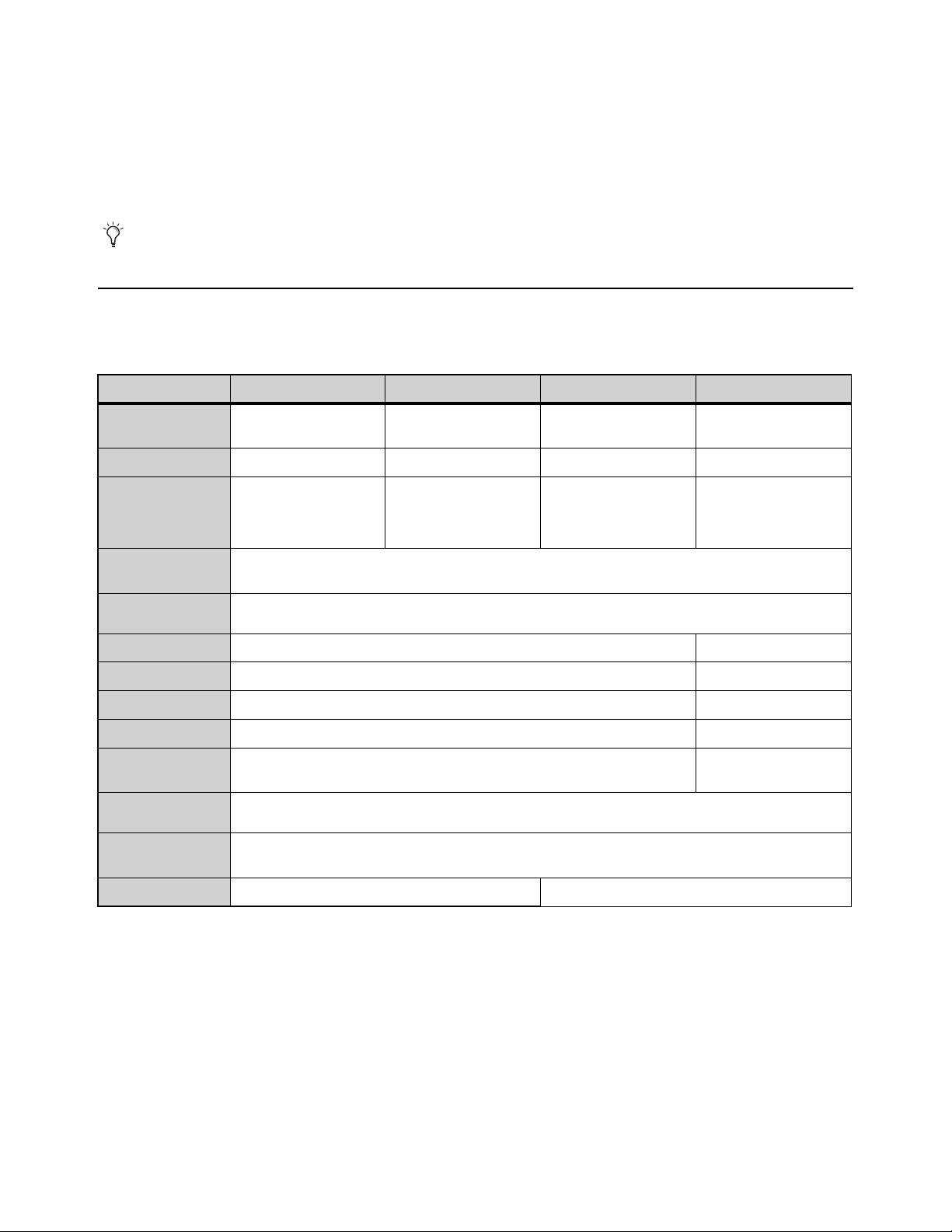
S6L Control Surface Features
The S6L control surface provides system controls, mix position audio I/O, and control and utility connections. The S6L control sur-
face is available in three models, the S6L-32D, S6L-24D, and the S6L-24C, which provide the following features and capabilities:
For complete system requirements and a list of qualified computers, operating systems, and third-party devices, visit
www.avid.com/S6Lsupport.
S6L-32D S6L-24D S6L-24C S6L-16C
Integrated Touch
Screens
1 Master Touch Screen,
3 Channel Touch Modules
1 Master Touch Screen,
2 Channel Touch Modules
1 Master Touch Screen
n/a
Faders
32 channel strips + 2 24 channel strips + 2 24 channel strips + 2
16 channel strips + 2
Channel Knob
Modules (CKM)
3 CKMs, each with 32
color-coded encoders, 32
high-resolution displays,
and tri-color indicators
2 CKMs, each with 32
color-coded encoders, 32
high-resolution displays,
and tri-color indicators
1 CKM with 32
color-coded encoders, 32
high-resolution displays,
and tri-color indicators
1 CKM with 32
color-coded encoders, 32
high-resolution displays,
and tri-color indicators
Master Live
Module
2 TFT displays with Soft Keys; Touch and Turn assignable encoder; 2 assignable faders;
monitoring, layout and snapshot controls; transport controls and function buttons
Metering
30-segment meters per channel, with pre- and post-fade metering options; Nominal indicator,
Expander/Gate status and Compressor/Limiter gain reduction meters
Analog inputs
8 XLR mic/line inputs with 48V and signal present LEDs
1 XLR mic/line input
Analog outputs
8 XLR outputs with mute and signal present LEDs
2 XLR outputs
Digital inputs
4 pairs of XLR stereo AES/EBU (8 channels total)
n/a
Digital outputs
4 pairs of XLR stereo AES/EBU (8 channels total)
n/a
Headphone
outputs
2 independent 1/4-inch TRS stereo headphone jacks
1 1/4-inch TRS stereo
headphone jack
Ancillary I/O
DVI-D video out, 4 USB 2.0 (2 rear, 1 front, 1 internal), ECx Ethernet port for wired/wireless remote control, GPIO
(8 in/8 out), 2 footswitch, Linear Time Code input, MIDI I/O
AVB Audio
Network ports
4, each providing etherCON (copper) or SFP (fiber optic) connections
Power supply
2 (1+1) redundant, internal hot-swappable PSUs
Dual redundant, internal
Introduction to the VENUE | S6L System 3
S6L-32D
S6L-24D
S6L-24C
VENUE | S6L-32D
VENUE | S6L-24D
VENUE | S6L-24C
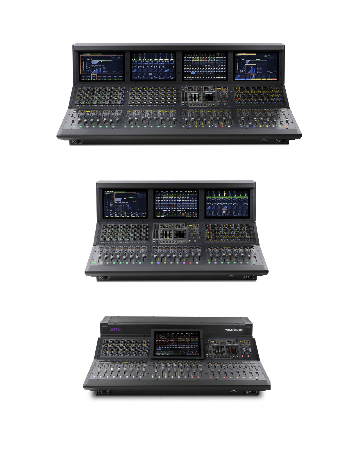
Introduction to the VENUE | S6L System 4
S6L-16C
Lights (S6L-24C and S6L-16C)
The S6L-24C provides 2x connectors (3-pin XLR) on the top panel for connecting goose-neck LED console lamps. Note that only
LED lights are supported on the S6L-24C. S6L-32D and S6L-24D control surfaces provide a built-in Light Bar to illuminate the
surface.
VENUE | S6L-16C

Introduction to the VENUE | S6L System 5
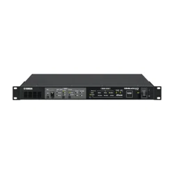
E6L Engine Features
The E6L engine provides the real-time processing engine for input and output channels, and Pro Tools | HDX DSP processing
card(s) for AAX DSP plug-ins. The E6L engine also provides connections for synchronization, control and utility in a 5U
rack-mountable enclosure. The E6L-192, E6L-144, and the E6L-112 provide the following features and capabilities in their basic
configuration:
E6L-192 E6L-144 E6L-112
Sample rates
96 kHz 96 kHz 96 kHz
Input channels
192 144 112
Input processing (per channel)
HPF, LPF, 4-band PEQ, Expander/Gate, Compressor/Limiter, Delay, 4 plug-in inserts,
hardware insert
Mix buses
96 + L-R, C/Mono 64 + L-R, C/Mono 48 + L-R, C/Mono
Output processing (per channel)
7-band PEQ, Compressor/Limiter, Delay, 4 plug-in inserts, hardware inserts
Matrix
24 x 24 16 x 16 16 x 16
VCAs
32 24 24
Monitor buses
2 stereo, each with independent control and routing
Graphic EQs (31-band)
32
Plug-in support
1 x HDX-192 DSP card,
expandable to up to four
HDX cards
1 x HDX-192 DSP card,
expandable to up to two
HDX cards
1 x HDX-192 DSP card,
expandable up to two
HDX cards
Plug-in slots
200 125 100
Pro Tools Recording/Playback
Record/play back up to 128 audio tracks via Ethernet AVB
AVB Audio Network Ports
2, each providing etherCON (copper) or SFP (fiber optic) connections
(Some base configurations with Stage 16s include an additional AVB-192 card)
I/O Sharing
Supports combinations of Stage 64, Stage 32s, and Stage 16 racks, up to 192 inputs total
(requires two AVB-192 Ethernet AVB Network Cards to share I/O)
Word Clock I/O
Input and Output, BNC, 75 Ohm coaxial
USB ports
4 USB 2.0 ports (2 front, 2 back)
Power supply
3 (2+1) redundant, internal hot-swappable PSUs
Dual redundant, internal
Rack spaces
5U
VENUE E6L
Introduction to the VENUE | S6L System 6
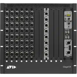
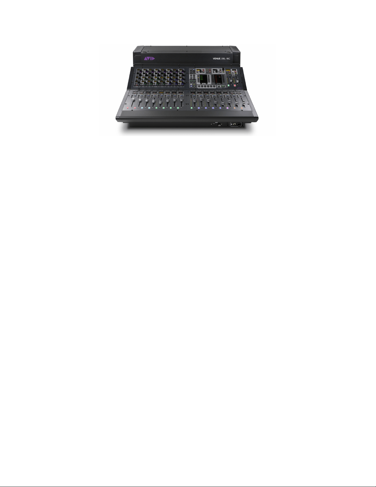
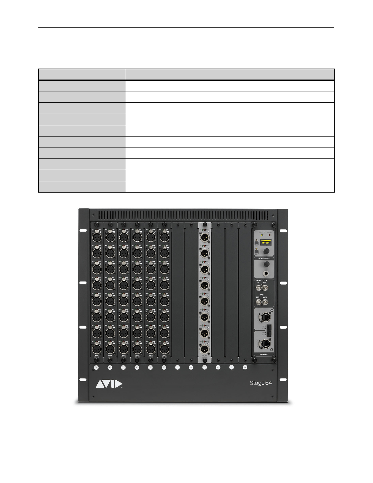
Stage 64 I/O Rack Features
Stage 64 provides remote stage I/O for S6L systems in a 10U rack-mountable enclosure. The S6L system supports redundant audio
network connections to up to three Stage 64 I/O racks. Audio network connections are made using supported copper Ethernet ca-
bles and/or fiber-optic cables (see Audio Network Connections).
I/O Rack Stage 64
Maximum I/O
64 input channels, 32 output channels
I/O card slots
12 (8 for input cards, 4 for output cards)
Sample rates
96 kHz
AVB Audio Network Ports
2, each providing etherCON (copper) or SFP (fiber optic) connections
Maximum cable length
Copper: 100 meters (328 feet); Fiber: 500 meters (1,640.4 feet)
MADI Outs
2 BNC; digital split outputs of Stage 64 inputs at 48 or 96 kHz; supports 64 channel MADI formats
Headphone confidence monitor
1/4-inch TRS stereo headphone jack with volume control; display for channel selection
Word Clock Out
BNC, 75 Ohm coaxial
Power supply
Dual redundant internal PSUs
Rack spaces
10U
Stage 64 I/O Rack front panel (48 x 8 configuration shown)
Introduction to the VENUE | S6L System 7
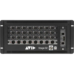
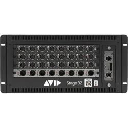
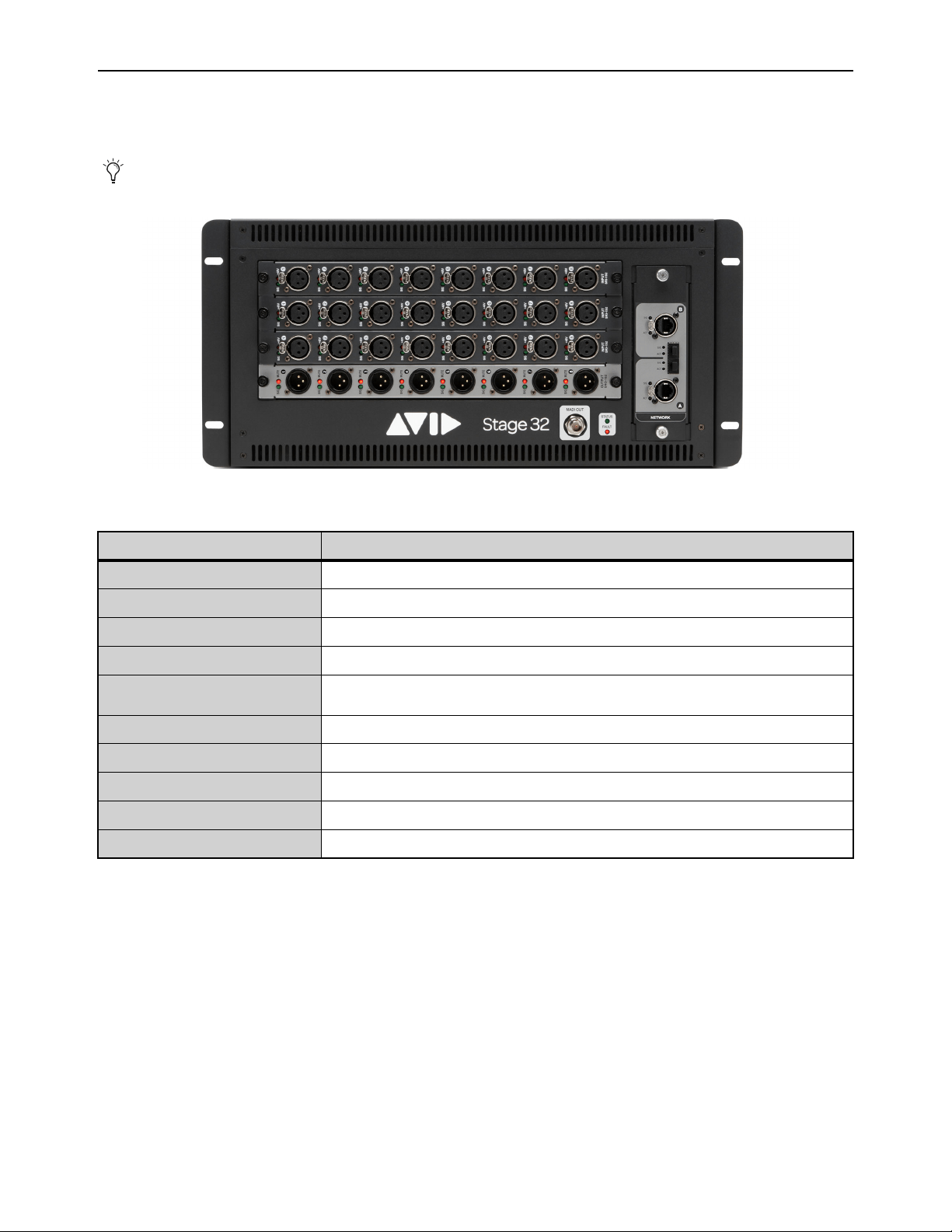
Stage 32 I/O Rack Features
Stage 32 provides remote stage I/O for S6L systems in a 5U rack-mountable enclosure. Up to four Stage 32 units can be connected
on supported systems. Audio snake connection are made using supported Ethernet cables (see Audio Network Connections).
The following table lists Stage 32 features and specifications:
Stage 32 requires 2x AVB-192 Network Cards in the E6L engine.
Stage 32 I/O
I/O Rack Stage 32
Maximum I/O
32 input/output channels @ 96 kHz with one Stage 32 rack
I/O card slots
4
Sample rates
96 kHz
AVB Audio Network Ports
2, each providing etherCON (copper) or SFP (fiber optic) connections
Maximum cable length
Copper: 100 meters (328 feet);
Fiber: 500 meters (1,640.4 feet) for Multi-Mode, 10,000 meters for Single Mode Fiber
MADI Outs
Single MADI output offers direct split of up to 32 inputs
Headphone confidence monitor
n/a
Word Clock Out
n/a
Power supply
Dual redundant internal PSUs
Rack spaces
5U
Introduction to the VENUE | S6L System 8
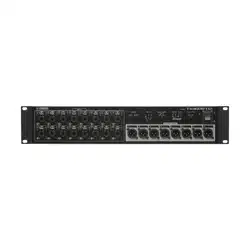
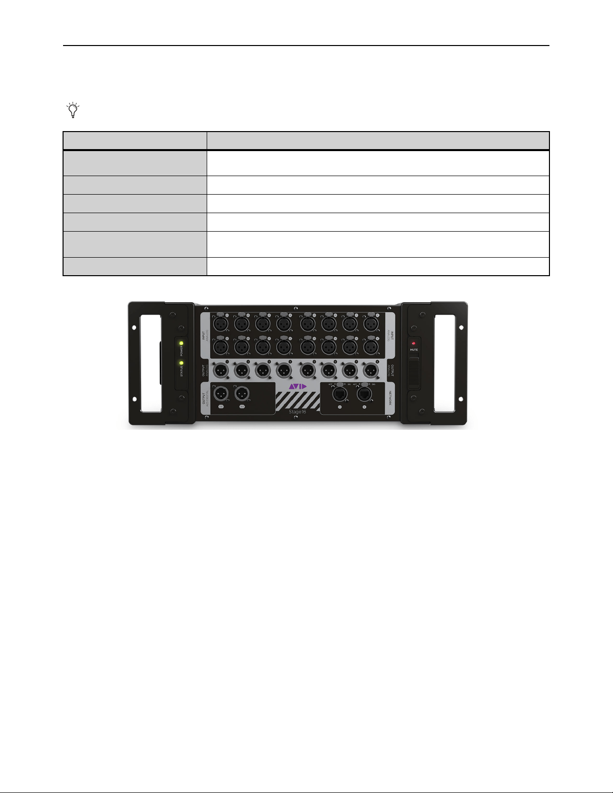
Stage 16 Remote IO Features
Stage 16 provides remote stage I/O for S6L systems in a 4U rack-mountable enclosure. Up to four Stage 16 boxes can be connected
on supported systems. Audio snake connection are made using supported Ethernet cables (see Audio Network Connections).
Stage 16 requires 2x AVB-192 Network Cards in the E6L engine.
I/O Rack Stage 16
Maximum I/O
16 analog input channels, 8 analog output channels, 4 AES digital output channels (on two
stereo connectors)
Sample rates
96 kHz (with S6L systems), 48 kHz (with S3L-X/S3L systems)
AVB Audio Network Ports
2 Neutrik etherCON RJ-45 Ethernet Network ports
Maximum cable length
100 meters (328 feet)
Power supply
Internal universal PSU (100V to 240V nominal 50–60 Hz) accepting standard IEC AC power
cables
Rack spaces
4U
Introduction to the VENUE | S6L System 9
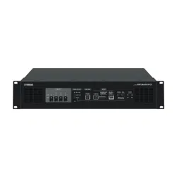
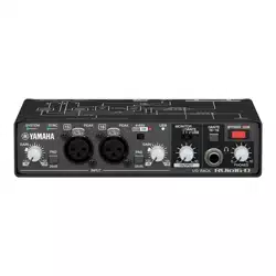
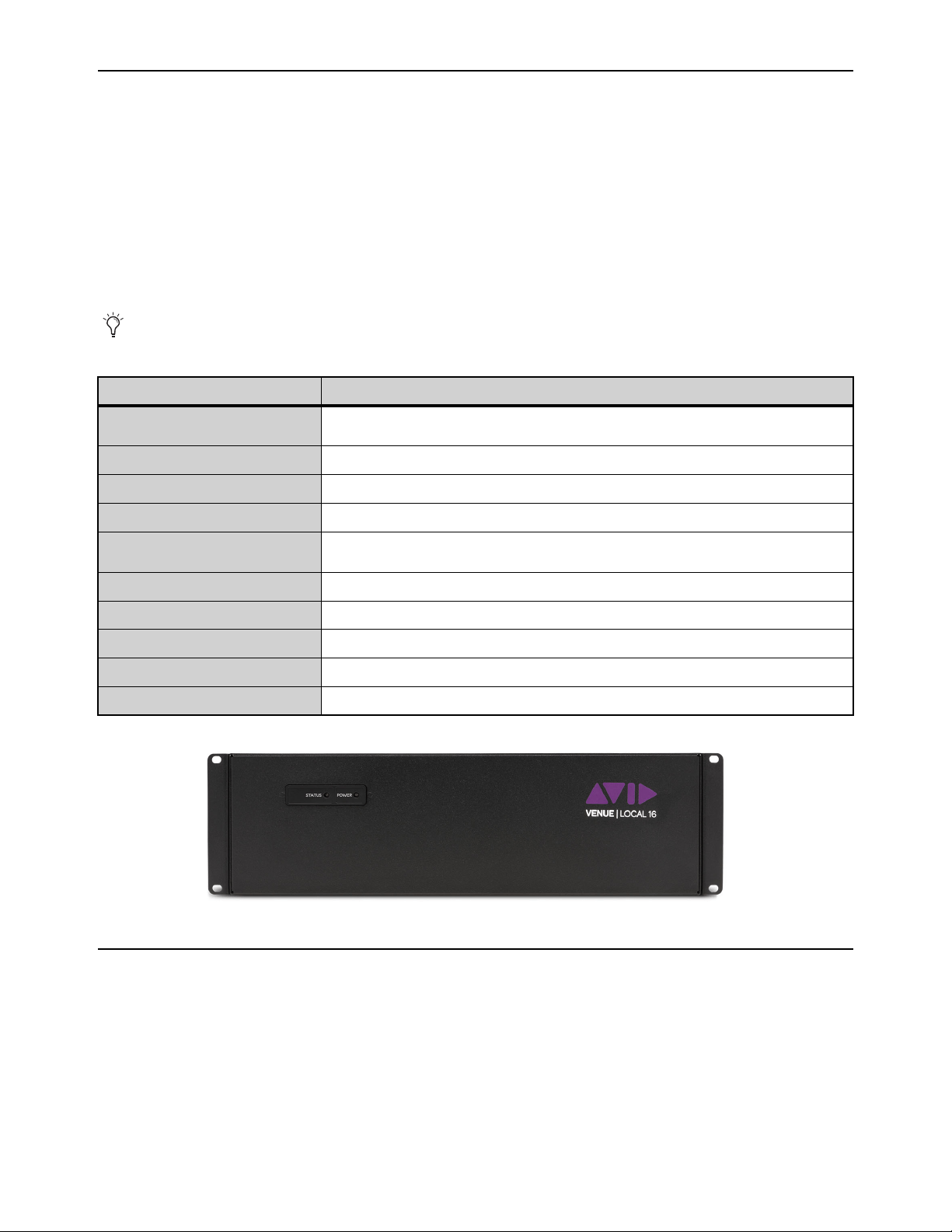
Local 16 I/O Features
Local 16 lets you expand your local I/O capabilities—or add primary local I/O if mixing on the S6L-16C control surface—with this
compact I/O rack. Features include:
• 8 XLR mic/line inputs, 8 XLR outputs, 4 pairs of XLR stereo AES/EBU inputs (8 channels total), 4 pairs of XLR stereo
AES/EBU outputs (8 channels total)
•3U rack
• Up to two Local 16 units can be connected on the local (console) S6L AVB Network ring when using S6L-16C. A single
Local 16 can be used with other S6L systems.
• Audio network connections are made using supported copper Ethernet cables and/or fiber-optic cables
• Local 16 connects to the control surface network ring (Ring 2)
The following table lists Local 16 features and specifications:
What’s Included
See the VENUE S6L Installation Guide.pdf for a complete list of what’s included with each system, additional required items (re-
quired but not included), and optional items.
Local 16 requires 2x AVB-192 Network Cards in the E6L engine.
I/O Rack Local 16
Maximum I/O
8 XLR mic/line inputs, 8 XLR outputs, 4 pairs of XLR stereo AES/EBU inputs (8 channels total),
4 pairs of XLR stereo AES/EBU outputs (8 channels total) @ 96 kHz with one Local 16 rack
I/O card slots
n/a
Sample rates
96 kHz
AVB Audio Network Ports
2, each providing etherCON (copper) or SFP (fiber optic) connections
Maximum cable length
Copper: 100 meters (328 feet);
Fiber: 500 meters (1,640.4 feet) for Multi-Mode, 10,000 meters for Single Mode Fiber
MADI Outs
n/a
Headphone confidence monitor
n/a
Word Clock Out
n/a
Power supply
Dual redundant internal PSUs
Rack spaces
3U
Local 16 I/O

Introduction to the VENUE | S6L System 10
Expansion Options
S6L systems can be expanded to add analog or digital IO, plug-in processing capability, and connectivity by adding any of the fol-
lowing options.
Stage 64 Expansion
You can expand the number of input and output channels by adding any of the following cards to a Stage 64, up to the maximum
of 8 input cards and 4 output cards:
SRI-192 Analog Input Card
SRO-192 Analog Output Card
DSI-192 Digital Input Card
DSO-192 Digital Output Card
DNT-192 Network Card
Up to three Stage 64s can be connected simultaneously (requires dual AVB-192 Network Cards in the E6L Engine). For require-
ments and connection diagrams see the VENUE S6L Installation Guide.pdf.
Stage 32
Stage 32 lets you connect up to 32 analog, digital, and/or Dante inputs and outputs in a rack that offers maximum I/O flexibility in
a smaller footprint for stage or remote I/O needs. Each Stage 32 supports up to a maximum 32 channels of inputs or outputs or a
combination of both. You can customize Stage 32 with any of the same analog I/O, digital I/O, and Dante card options available
for Stage 64, including SRI-192 Analog Input cards, SRO-192 Analog Output cards, DSI-192 Digital Input cards, DSO-192 Digital
Output cards, and DNT-192 Dante Option cards.
Up to four Stage 32 units can be networked at once (requires dual AVB-192 Network Cards in the E6L engine), and you can com-
bine Stage 32 with other VENUE S6L I/O units up to the maximum capacity of your system configuration. For requirements and
connection diagrams see the VENUE S6L Installation Guide.pdf.
Stage 16
Stage 16s can be integrated into S6L systems (requires dual AVB-192 Network Cards in the E6L Engine). For supported config-
urations, requirements, and connection diagrams see the VENUE S6L Installation Guide.pdf.
Local 16
Local 16 can be integrated into S6L systems (requires dual AVB-192 Network Cards in the E6L Engine). Up to two Local 16s can
be used with S6L-16C; other systems support one Local 16.
E6L Expansion
You can expand processing, connectivity, and IO capabilities by adding any of the following cards to an E6L engine.
• HDX-192 DSP Expansion Cards
• AVB-192 Network Card
• MADI-192 MADI Option Card
• WSG-HD Waves SoundGridOption Cards
S6L Control Surface Expansion
S6L-24 systems can be upgraded to S6L-24D by adding Channel Touch Modules. Contact your VENUE reseller for more infor-
mation.
Introduction to the VENUE | S6L System 11
Operational Requirements
Temperature and Ventilation
S6L system devices should be operated away from heat sources and with adequate ventilation.
Storage
S6L system devices should be stored and transported at temperatures not lower than 0 degrees F (–18 degrees C) and not exceeding
140 degrees F (60 degrees C).
Operation
S6L system devices should be operated at temperatures not lower than 40 degrees F (4 degrees C) and not exceeding 104 degrees F
(40 degrees C).
During operation, the left and right end caps on the back of the S6L control surface, the front and back of the E6L engine, and the
fans on the back of the Stage 64 should be exposed to ambient air. Do not block the ventilation holes on any S6L system component.
Do not operate in direct sunlight or at extreme ambient temperatures.
Water and Moisture
S6L system devices should be operated away from sources of direct moisture and should be kept clear of liquids that might spill
into the units. If condensation is present on the unit, leave the unit to dry in ambient air for at least one hour before powering the
unit on.
Cleaning and Maintenance
Use a dry cloth to clean the surfaces of the S6L components. Do not apply any cleaning solutions, spray cleaners, or abrasives
to the surfaces of the components.
Use a microfiber cloth (included with the S6L control surface) to clean the touch screens. Do not apply any cleaning solutions,
spray cleaners, or abrasives.
Hardware monitoring and automatic warnings are provided for temperature, power and other factors. For more information,
see
Hardware Monitoring Window.
Storage humidity range 5% to 95%, non-condensing
Operating humidity range 20% to 80%, non-condensing

Introduction to the VENUE | S6L System 12
Cabling Requirements
Power Connections
Power connections on all S6L system devices are auto voltage-selecting (100 to 240V nominal, 90-260V maximal, 50–60 Hz).
Make sure your power source is correctly rated for the number of units you are connecting. A surge-protected power source (not
included) is highly recommended.
Audio Network Connections
This section describes the audio network cabling requirements for S6L system components. Audio network connections between
S6L system components can be made using either copper or fiber-optic audio network cables. Cable types can be mixed within a
system, but only one type of connection (copper or fiber) can be used per audio network connection.
Copper
Shielded Cat 5e (350 MHz) or better Ethernet cable with Neutrik etherCON
connectors are required, supporting a distance of up to
100 meters per connection.
Fiber-Optic
S6L systems support single-mode fiber (SMF) or multi-mode fiber (MMF) cable to make audio network connections between com-
ponents, as follows:
SMF
Requires single-mode 9/125 OS1 or OS2 cables with duplex LC connectors and two qualified single-mode SFP transceivers
per connection, supporting distances of up to 10 kilometers
MMF
Requires multi-mode 50/125 OM2 or better cables with duplex LC connectors and two qualified multi-mode SFP transceiver
modules per connection, supporting distances of up to 500 meters.
Pro Tools Connections
Shielded Cat 5e (350 MHz) or better Ethernet cable with RJ-45 connectors is required for the AVB audio connections to Pro Tools.
ECx Ethernet Control Connections
Standard Cat 5e Ethernet cable with RJ-45 connectors are supported for ECx remote control connections to a client computer or
wireless/wired router.
System Requirements and Compatibility
Avid can only assure compatibility and provide support for hardware and software it has tested and approved. For complete system
requirements and a list of qualified computers, operating systems, hard drives, and third-party devices, visit:
www.avid.com/S6Lsupport
For complete information on connecting S6L system components, see the VENUE S6L Installation Guide.pdf.
Visit
www.avid.com/S6Lsupport for a list of qualified SFP transceivers for use with S6L systems.

Introduction to the VENUE | S6L System 13
Resources
The Avid website (www.avid.com) is your best online source for information to help you get the most out of your Avid system.
The following are just a few of the services and features available.
Account Activation and Product Registration
Activate your product to access downloads in your Avid account (or create an account if you don’t have one). Register your pur-
chase online, download software, updates, documentation, and other resources.
https://www.avid.com/account
Support and Downloads
Contact Avid Customer Success (technical support); download software updates and the latest online manuals; browse the Com-
patibility documents for system requirements; search the online Knowledge Base or join the worldwide Avid user community on
the User Conference.
https://www.avid.com/Support/index.html
For S6L system-specific support, visit:
www.avid.com/S6Lsupport
Get started learning the ins and outs of S6L using the many Avid Live Sound videos on YouTube.
Training and Education
Study on your own using courses available online, find out how you can learn in a classroom setting at an Avid-certified training
center, or view a webinar. For example, check out the live sound webinars hosted by Robert Scovill:
https://www.avid.com/resources/live-sound-webinar-registration
Products and Developers
Learn about Avid products; download demo software or learn about our Development Partners and their plug-ins, applications, and
hardware.
https://www.avid.com/Products/index.html
Activation
You must activate each S6L system component using the Activation Card included in each component’s shipping package. Acti-
vating your product lets you receive the following:
• VENUE system software and plug-ins
• Technical support
• Software update and upgrade notices
• Hardware warranty information
Introduction to the VENUE | S6L System 14
Conventions Used in This Guide
All of our guides use the following conventions to indicate touch screen gestures and key commands:
:
The names of selectable on-screen elements that contain text are displayed in a different font.
The names of physical switches on the S6L control surface are in displayed in bold text.
The following symbols are used to highlight important information:
When Using a Mouse with S6L
For the best experience, Avid recommends you use qualified external monitors with touchscreen capabilities for accessing the ex-
ternal VENUE software screen. When discussing on-screen selections, “touch” is used. If you are using a mouse to control the ex-
ternal VENUE software screen, “touch” is synonymous with “click,” “touch-and-hold” is synonymous with “right-click,” “dou-
ble-tap” is synonymous with “double-click” and “touch, hold and slide” is synonymous with “click-and-drag.”
How to Use this PDF Guide
This PDF provides the following useful features:
• The Bookmarks on the left serve as a continuously visible table of contents. Click on a subject heading to jump to that page.
• Click a + symbol to expand that heading to show subheadings. Click the – symbol to collapse a subheading.
• The Table of Contents provides active links to their pages. Select the hand cursor, allow it to hover over the heading until it
turns into a finger. Then click to locate to that subject and page.
• All cross references in blue are active links. Click to follow the reference.
• Select Find from the Edit menu to search for a subject.
• When viewing this PDF on an iPad, it is recommended that you open the file using iBooks to take advantage of active links
within the document. When viewing the PDF in Safari, touch the screen, then touch
Open in “iBooks”
Convention Action
Touch Touch an element on-screen briefly and immediately release your finger.
Used to activate a function or toggle a parameter value.
Swipe Touch an area on-screen and drag left/right/up/down. Used to scroll ele-
ments, where available.
Touch, Hold, and Drag/Slide On the external VENUE software screen, touch and hold a parameter, then
slide your finger to adjust parameters on-screen, or to drag elements.
Touch-and-Hold On the external VENUE software screen, touching and holding an element
on-screen, then releasing lets you access pop-up menu options, where
available.
Double-Tap Quickly tap an on-screen element such as a name field to edit its name
Options > System On the external VENUE software screen, touch Options, then touch the
System tab to display the System page.
Shift-touch/Ctrl-touch/Alt-touch On the external VENUE software screen, press and hold Shift (or other key-
board modifier) on the keyboard, then touch an on-screen parameter.
User Tips are helpful hints for getting the most from your system.
Important Notices include information that could affect your data or the performance of your system.
Shortcuts show you useful keyboard or mouse shortcuts.
Cross References point to related sections in this guide and other VENUE guides.
S6L Control Surface Overview 15
S6L Control Surface Overview
The section provides an overview of S6L control surface controls, and front and back panel audio, control, and power connections.
S6L Control Surface Top Panel Overview
The S6L control surface is available in four models, S6L-32D, S6L-24D, S6L-24C, and S6L-16C. Most available controls are com-
mon across all models, and only vary in quantity between models. Unlike other control surfaces, the S6L-16C does not include a
Master Touch Screen (use the external screen instead).
S6L is oriented vertically. On S6L-32D and 24D, each fader bank (except the fader bank under the Master Live Module) is oper-
ationally associated with the Channel Knob Module and the Channel Touch Module (if present) above it. All three operate in uni-
son: bank channels to a fader bank, select a banked channel, adjust that channel’s parameters on the associated Channel Knob Mod-
ule, and view the banked channels’ parameters on the associated Channel Touch Module. On S6L-24C and S6L-16C, the single
Channel Knob module provides access to the currently banked or selected channel. You can also select a channel from a Channel
Touch Module (if present) and adjust its parameters on the associated Channel Knob Module.
The Master Live Module provides control over global system parameters such as channel banking, snapshots and monitoring. The
Master Touch Screen, above the Master Live Module on S6L-32D and 24D and in the center on 24C, provides access to all system
channels (via Universe view), to parameters for the currently Attentioned channel (via Channel view), and a local view of the chan-
nels banked to the faders below the Master Live Module (via Meters view). S6L-16C does not include a Master Touch Screen but
provide connection, configuration, and Universe views on the external screen instead.
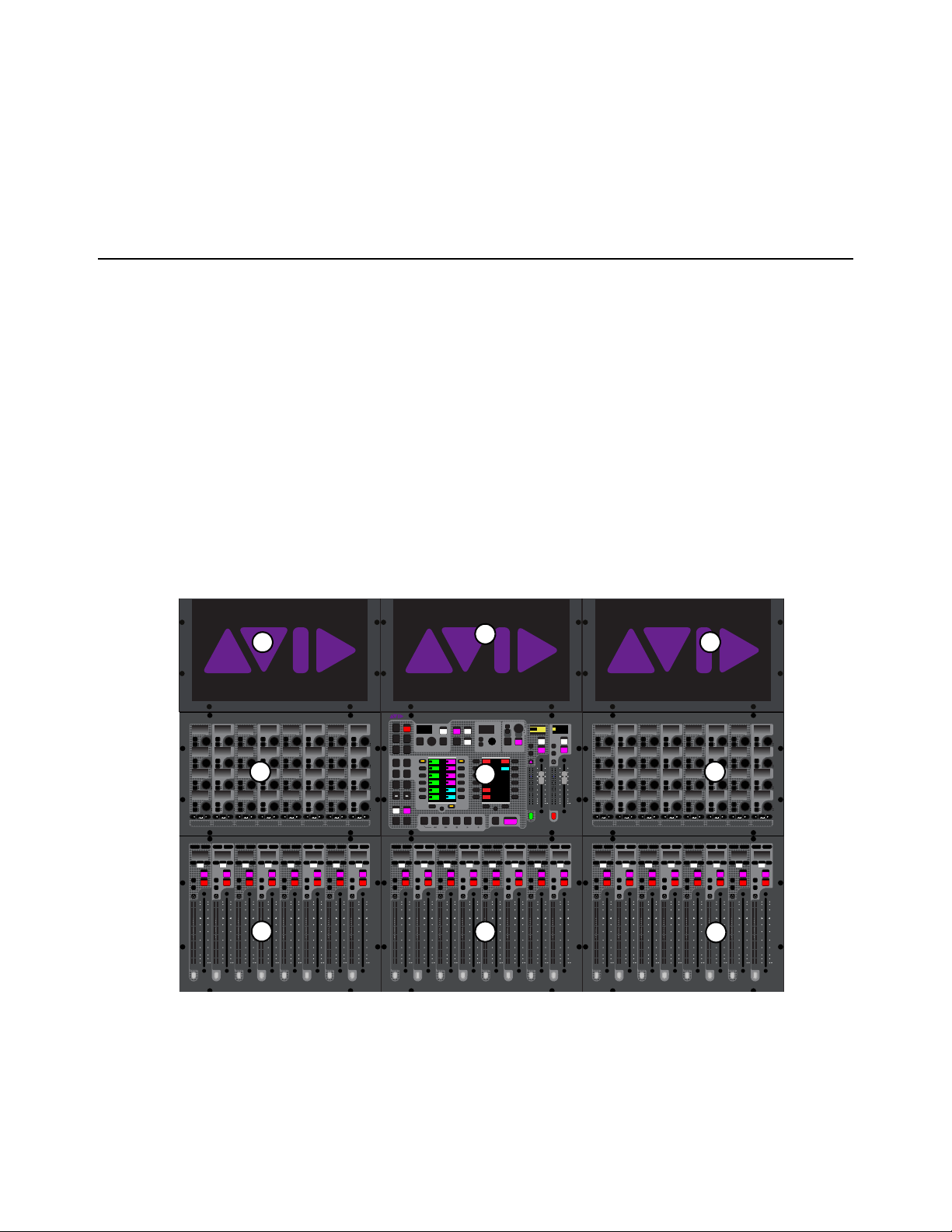
S6L top panel (S6L-24D shown)
1 –
Fader Banks
2 – Channel Knob Modules (CKM)
3 – Channel Touch Module (CTM)
4 – Master Live Module (MLM)
5 – Master Touch Screen (MTS)
60
40
30
20
10
5
0
6
12
60
40
30
20
10
5
0
6
12
Select
Solo
Select
Solo
Select
Solo
Select
Solo
Select
Solo
Select
Solo
Select
Solo
Select
Solo
BAS
Menu Safe
Mute
Y
X
Y
X
Y
X
Y
X
Y
X
Y
X
Y
X
Y
X
BAS
Menu Safe
Mute
BAS
Menu Safe
Mute
BAS
Menu Safe
Mute
BAS
Menu Safe
Mute
BAS
Menu Safe
Mute
BAS
Menu Safe
Mute
BAS
Menu Safe
Mute
60
40
30
20
10
5
0
6
12
60
40
30
20
10
5
0
6
12
60
40
30
20
10
5
0
6
12
60
40
30
20
10
5
0
6
12
60
40
30
20
10
5
0
6
12
60
40
30
20
10
5
0
6
12
60
30
21
15
9
3
0
3
9
15
60
30
21
15
9
3
0
3
9
15
60
30
21
15
9
3
0
3
9
15
60
30
21
15
9
3
0
3
9
15
60
30
21
15
9
3
0
3
9
15
60
30
21
15
9
3
0
3
9
15
60
30
21
15
9
3
0
3
9
15
60
30
21
15
9
3
0
3
9
15
Nom
60
40
30
20
10
5
0
6
12
60
40
30
20
10
5
0
6
12
Select
Solo
Select
Solo
Select
Solo
Select
Solo
Select
Solo
Select
Solo
Select
Solo
Select
Solo
BAS
Menu Safe
Mute
Y
X
Y
X
Y
X
Y
X
Y
X
Y
X
Y
X
Y
X
BAS
Menu Safe
Mute
BAS
Menu Safe
Mute
BAS
Menu Safe
Mute
BAS
Menu Safe
Mute
BAS
Menu Safe
Mute
BAS
Menu Safe
Mute
BAS
Menu Safe
Mute
60
40
30
20
10
5
0
6
12
60
40
30
20
10
5
0
6
12
60
40
30
20
10
5
0
6
12
60
40
30
20
10
5
0
6
12
60
40
30
20
10
5
0
6
12
60
40
30
20
10
5
0
6
12
60
30
21
15
9
3
0
3
9
15
60
30
21
15
9
3
0
3
9
15
60
30
21
15
9
3
0
3
9
15
60
30
21
15
9
3
0
3
9
15
60
30
21
15
9
3
0
3
9
15
60
30
21
15
9
3
0
3
9
15
60
30
21
15
9
3
0
3
9
15
60
30
21
15
9
3
0
3
9
15
Nom
MIXMIXMIXPLUG-INSDYNAMICSEQINPUTCHANNEL
In
Sel
In
Sel
In
Sel
In
Sel
In
Sel
In
Sel
In
Sel
In
Sel
In
Sel
In
Sel
In
Sel
In
Sel
In
Sel
In
Sel
In
Sel
In
Sel
In
Sel
In
Sel
In
Sel
In
Sel
In
Sel
In
Sel
In
Sel
In
Sel
In
Sel
In
Sel
In
Sel
In
Sel
In
Sel
In
Sel
In
Sel
In
Sel
MIXMIXMIXPLUG-INSDYNAMICSEQINPUTCHANNEL
In
Sel
In
Sel
In
Sel
In
Sel
In
Sel
In
Sel
In
Sel
In
Sel
In
Sel
In
Sel
In
Sel
In
Sel
In
Sel
In
Sel
In
Sel
In
Sel
In
Sel
In
Sel
In
Sel
In
Sel
In
Sel
In
Sel
In
Sel
In
Sel
In
Sel
In
Sel
In
Sel
In
Sel
In
Sel
In
Sel
In
Sel
In
Sel
VENUE | S6L
Solo Solo
Home
Config
VCAs
Outputs
Layouts
Inputs
Flip
Recall
Trans
F1 F2 F3 F4 F5
NEXT
PREV
Store
Y
X
Y
X
AFL
Dim
In
Sel
SNAPSHOTS
Talk
Back
Multi
Select
Encoder
Assign
Select
Clear
Tap
Tempo
Multi
Assgn
Default Fine
OK Cancel
Over
Write
Mix to
Mon
Solo
Clear
60
40
30
20
10
5
0
6
12
60
40
30
20
10
5
0
6
12
8All
Preview
ASSIGNABLE ENCODER MONITORING
Push A/BHold SIP
SHIFT
ALT
CTRL
ESC
Mute Mute
A
B
Nom
30
21
15
9
3
0
3
9
15
30
21
15
9
3
0
3
9
15
Inputs/Outputs
Next
Global Controls
0.0 dB
L
Left
0.0 dB
Kick
Mute Group 1
Mute Group
Function KeysMute Group 2
Mute Group 3
Mute Group 4
Mute Group 5
Mute Group 6
M1
M2
M3
M4
M5
M6
0
01/011
reset all inputs
0.0 dB
CH 1
Kick
Ch 1-16
1-16
Aux 1-8
1-8
Aux 9-16
Aux 17-24
Aux 25-32
25-32
VCA 1-8
1-8
VCA 9-16
9-16
Ch 17-32
17-32 9-16
Ch 33-48
33-48 17-24
Ch 49-64
49-64
Ch 65-80
65-80
Ch 81-96
81-96
1
2
3
4
5
1
1
2
3
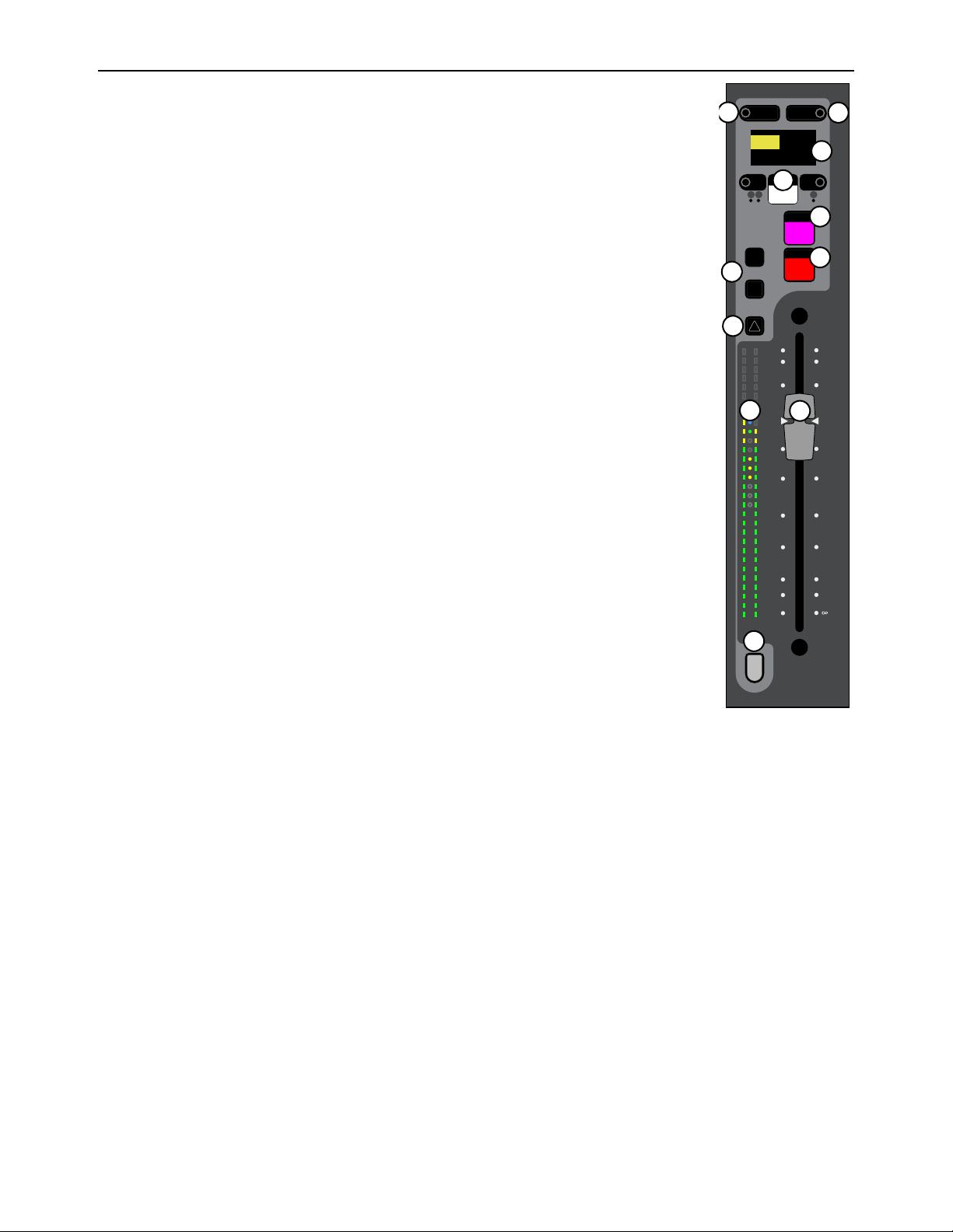
S6L Control Surface Overview 16
Fader Banks
Each fader bank provides eight channel strips to control input or output channels, depending on the type
of channels banked to the faders. Each channel strip provides the following controls and indicators:
1 –
Channel Menu
2 – Channel Safe
3 – Channel Display
4 – Mute
5 – Solo
6 – Select
7 – Attention
8 –
X and Y Switches
9 – Channel and Gain Reduction Meters
10 – Fader
11 – Channel Color Switch
60
40
30
20
10
5
0
6
12
Select
Solo
Y
X
Menu Safe
Mute
60
30
21
15
9
3
0
3
9
15
AS B
CH 1
Ch 1
0.0 dB
1
5
2
4
6
8
7
9
11
10
3
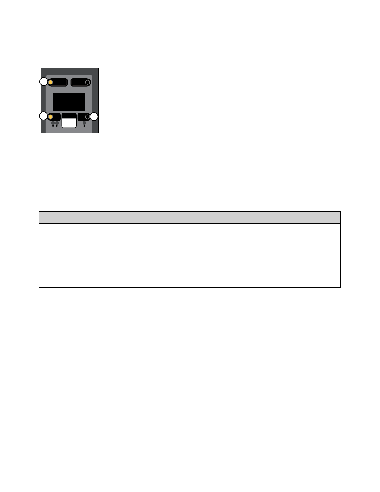
S6L Control Surface Overview 17
Channel Menu
The Channel Menu provides several pages of parameters that apply to the banked channel. The Menu switch (“1” in the figure be-
low) enables the Channel Menu, which is shown in the channel display. The Left and Right Menu switches (2 and 3 in the figure
below) toggle the currently displayed Channel Menu parameter.
To use the Channel Menu:
1 Press Menu so it lights. The first page of the Channel Menu appears in the channel display.
2 Press Menu again to cycle through the available pages of Channel Menu options.
3 To toggle the parameter currently shown in the channel display, press the Left and Right Menu switches, as available. Each
Menu switch has an LED that lights when the associated parameter is enabled.
The following table provides a description of each Channel Menu page and the function of the Left and Right Menu switches for
each page:
:
* By default, channel Solo is routed to Monitor bus A. When Monitor A and B are selected, the channel is assigned to both Monitor buses,
both Menu switch LEDs are lit and “Mon A+B” appears in the Channel Menu Monitor page. For more information, see
Routing Chan-
nels to the Monitor Buses.
S6L Channel Menu
Channel Menu Page Parameter Left Menu Switch Right Menu Switch
Source/Destination
For an input channel, show and
toggle channel source.
For an output channel, show chan-
nel destination.
For input channels, enables the
hardware input patched to the
channel in the Patchbay as the
source
For input channels, enables the
corresponding Pro Tools Virtual
Soundcheck input as the source
for the channel
Monitor
Show and route channel Solo to
Monitor bus A and/or B.
Routes the channel Solo to
Monitor Bus A*
Routes the channel’s Solo to
Monitor Bus B*
Safe Mode
Engage a Safe mode not targeted
as the global safe mode.
Engages Safe
(automation, solo or bank)
Engages Safe
(automation, solo or bank)
Menu Safe
Mute
AS B
Ch 1:Stage1Analg1
Source
1
3
2

S6L Control Surface Overview 18
Channel Safe
Each channel strip provides a dedicated Channel Safe switch that lets you Automation, Solo (input channels only), or Bank Safe
the currently banked channel. The Safe mode engaged by the Channel Safe switch is defined globally for input and output channels
in the Channel Safe Switches section of the
Options > Interaction page of the external screen, (see
Interaction for more informa-
tion).
The channel strip provides the following Channel Safe controls and indicators:
1 – Safe
The Safe switch toggles safe on the channel.
2 – Safe LEDs
These LEDs light to indicate channel safe status, as follows:
• When A lights green, Automation Safe is enabled.
• When S lights yellow, Solo Safe is enabled.
• When B lights green, Bank Safe is enabled.
Channel Display
The channel display shows information for the currently banked channel such as the channel number and/or name, the current level
in dB for the banked channel, hardware assignment and current fader value, or a Channel Menu page if Menu is engaged.
Mute
Mute explicitly mutes the channel, removing the channel’s audio signal from any post-mute audio path, including L-R, C/Mono
buses, Groups, post-fader Direct Outs, and any post fader Aux sends, and lights solid red when engaged.
Solo
Solo sends the channel’s audio signal to the Monitor buses (when in AFL or PFL solo mode) or mutes all un-soloed input channels
(when in SIP solo mode). The S6L system provides two discrete Monitor buses, which can be configured to feed either or both
headphone outputs, and any number of system hardware outputs. See Soloing and the Monitor Buses for more information.
S6L Channel Menu controls
You can also safe channels using the Channel Knob Modules (CKM) and the Channel Menu. For more information see Man-
aging Snapshots, Bank Safing Channels and Solo Safing Channels.
Channel Displays can be optimized for easier viewing of channel name using the
Use Simple OLEDs setting.
A channel can be implicitly muted, for example, when it is muted as part of a Mute Group or VCA. See
Muting and Mute
Groups for more information. When a channel is implicitly muted, the Mute switch flashes red. Pressing Mute when a channel
is implicitly muted toggles the channel into or out of mute.
Menu Safe
Mute
AS B
CH 1
Ch 1
0.0 dB
1
2
2

S6L Control Surface Overview 19
Select
Select selects a channel locally, targeting the channel for processing using the 32 encoders on the associated Channel Knob Mod-
ule (CKM). From the CKM you can access channel processing functions such as EQ and dynamics via Channel Control mode (see
Channel Control Mode for more information).
Select also highlights that channel on any associated Channel Touch Module (CTM)–the screen in line with the fader bank from
which you selected the channel (only available on S6L-32D and 24D). You can select multiple channels for batch processing (Multi
Select). You can also deselect a channel, which enables Channel Strip mode on the associated CKM (see
Channel Strip Mode for
more information).
S6L-24C/16C and Local Select
On the S6L-24C and S6L-16C, pressing Select on any strip focuses that channel on the CKM. In addition:
• When any Channel is selected, the MTS enters Channel View for the selected channel.
• When no Channel is selected, the CKM is in Vertical mode for the faders directly below the CKM.
• If a Channel is selected but no parameter type was previously selected, the Channel parameters are displayed on the CKM.
Attention
Attention attentions a channel globally, targeting the channel to the Master Touch Screen (MTS) and by default to Flex Channel A
on the Master Live Module (see
Flex Channels for more information). Attention lets you focus on an important channel on the
MTS and a Flex Channel, keeping it visible and accessible at all times, while still allowing you to select other channels from the
fader banks (using
Select) and adjust their parameters on their respective CKMs and CTMs, if any.
Attention also targets the respective channel on the external screen, from which you can view and adjust the attentioned channel’s
parameters. You can also select multiple channels using Attention and apply an action to all selected channels at once, such as ap-
plying a high-pass filter to multiple channels at the same time (Multi-Select).
X and Y Switches
The X and Y switches provide convenient single-switch controls for the associated channel’s built-in dynamics processors, as fol-
lows:
X
Toggles Expander/Gate on/off. Its LED lights when the Exp/Gate is on. This applies to input channels only.
Y
Toggles Compressor/Limiter on/off. Its LED lights when the Comp/Lim is on.
Selecting a channel banked to the fader bank below the Master Live Module targets the channel to the rightmost CKM and CTM.
You can also attention channels by touching a channel tile on Master Touch Screen (MTS). See Master Touch Screen (MTS)
for more information.
For more information on selecting and attentioning channels, see Selecting Channels.
These switches can be customized, globally, using Events.

S6L Control Surface Overview 20
Channel and Gain Reduction Meters
Each channel strip features dual 30-segment signal level meters and a dedicated 10-segment dynamics meter.
Channel Level Meter
For mono channels, only the left meter shows level. For stereo channels, both meters show signal level. The pickoff point for the
input and output channel meters is set on the Options > Interaction page. See Metering for information.
Dynamics Meter
The channel dynamics meter, located between the two channel level meters, show gate activity, gain reduction,
and also provides a 0 dB indicator.
1 – 0 dB Indicator
The 0 dB indicator LED begins to light blue when the fader is near 0 dB. As the fader moves closer to 0 dB the
LED gets brighter and is brightest when at 0 dB, making it easier to set the fader to 0 / unity. The 0 dB LED
also lights blue when Flip to Faders is enabled and gain or a similar (dB) parameter is on the fader. VCA con-
tribution also affects the state of the 0 dB indicator.
2 – Gate Meter
The gate meter provides indication of the corresponding channel’s built-in expander/gate via three LEDs,
which light to indicate gate activity as follows:
3 – Gain Reduction Meter
The gain reduction meter provides indication of gain reduction applied by the channel’s built-in compressor/limiter via six LEDs,
and light to indicate comp/lim activity as follows:
:
Fader
The fader controls the output level for the currently banked input or output channel. When Flip to Faders is active, the fader controls
the send level of the parameter currently flipped to faders (see Flip for more information).
LED LED Color Expander Status Gate Status
1 (Top)
Green 0 dB gain reduction Gate Open & Hold
2
Yellow 3 dB gain reduction Gate Released
3 (Bottom)
Red >21 dB gain reduction Gate Closed
No LED illuminated Not in circuit
LED LED Color LED illuminates at... LED at full brightness at...
1 (top)
Yellow
>0 dB gain reduction 1.5 dB gain reduction
2
Yellow
>1.5 dB gain reduction 3 dB gain reduction
3
Yellow
>3 dB gain reduction 6 dB gain reduction
4
Yellow
>6 dB gain reduction 9 dB gain reduction
5
Yellow
>9 dB gain reduction 15 dB gain reduction
6 (bottom)
Yellow
>15 dB gain reduction 21 dB gain reduction
No LED illuminated Not in circuit
Gain Reduction meters can be used to trigger
Events.
You can set a preference so that touching a fader automatically attentions that channel. See Channel Selection for more in-
formation.
1
2
3
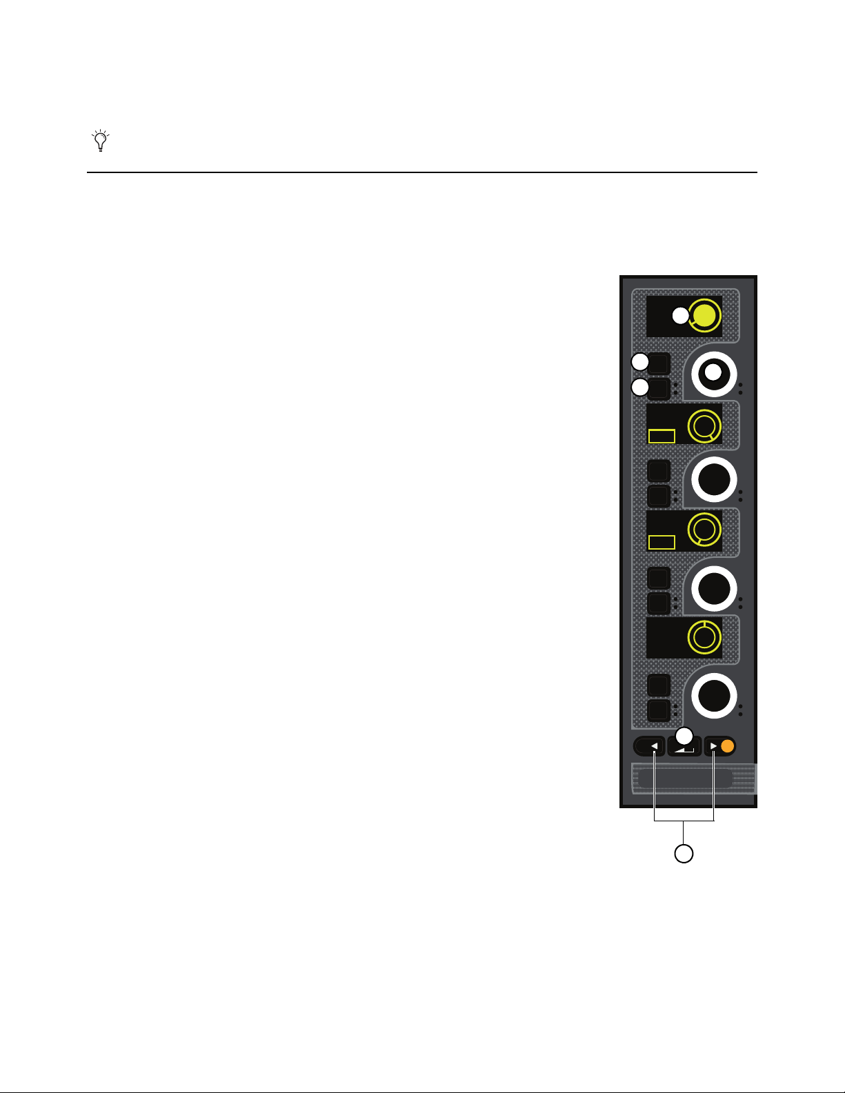
S6L Control Surface Overview 21
Channel Color Switch
This switch lights in the color as defined in the external VENUE software (see Color-Coding Channels from the External
Screen) and/or from the Master Touch Screen (see Color-Coding Channel from the Universe View).
Channel Knob Modules (CKM)
Each Channel Knob Module provides channel parameter control via 32 dual-function encoders that provide switch and rotary func-
tions. Each CKM is associated with the bank of eight faders below it, and the Channel Touch Module above it (if present). The
CKM operates in one of the following modes: Channel Strip mode or Channel Control mode.
1 – Encoder Display
The encoder display shows the parameter that is targeted to the encoder, the value of the parameter
(such as dB level for gain or frequency of an EQ band), and a “virtual” encoder showing the po-
sition of the encoder relative to the parameter value. For gain parameters such as Input Gain and
High--Pass Filter (HPF), the virtual encoder fills in to indicate level. For bus assign parameters,
the encoder surround fills in completely when the corresponding channel is assigned, and is empty
(black) when the channel is unassigned.
The display also shows the name and status of parameters that you can toggle on/off (in/out), such
as Pad or HPF, and lights when that parameter is enabled. The circle in the center of the encoder
ring displays the status of the encoder press function (if any), such as on/off.
2 – Sel
Sel assigns a secondary parameter to the corresponding encoder, or toggles a secondary function
of the current parameter, where available.
3 – In
In toggles an individual parameter on/off, where available. For example, when EQ is assigned to
the CKM, pressing the
In switch for the knob controlling Lo band gain toggles that filter in/out.
The switch lights when the parameter is enabled (in).
4 – Encoder
Rotating the encoder adjusts the currently assigned parameter, as shown in the encoder display.
For certain parameters, pressing the encoder toggles the parameter on/off (such as the Hi Gain pa-
rameter when EQ is assigned). Encoders are color-coded by function. See
Encoder Color Cod-
ing for more information.
5 – Channel Control Function Switch
The Channel Control Function switch assigns a group of parameters for the currently selected
channel to the 32 encoders on the CKM. See
Channel Control Functions for more information.
6 – Parameter Bank Switches
The Left and Right Parameter Bank switches let you assign the next or previous page of parame-
ters to the encoders, and are available in both Channel Strip and Channel Control modes. A switch
lights when there is a previous or next page of parameters to access.
These switches can be customized using
Events.
CHANNEL
In
Sel
In
Sel
In
Sel
In
Sel
HPF
20 Hz
Aux 1
-11.2 dB
LPF
20.00 kHz
<0>
Pan
Post
On
IN
IN
ON
1
2
3
4
5
6
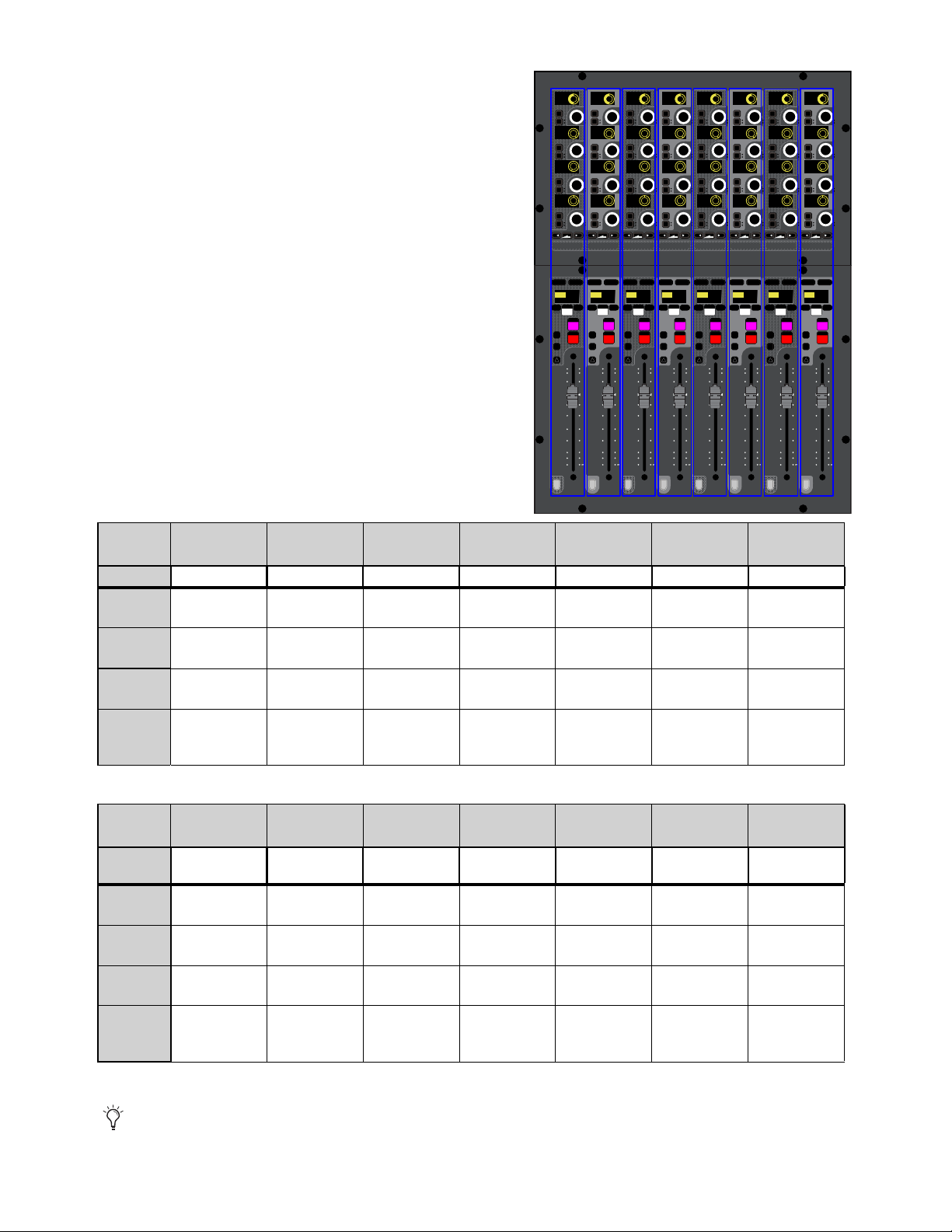
S6L Control Surface Overview 22
Channel Strip Mode
When no channels are selected from the corresponding fader bank, the
CKM operates in Channel Strip mode in which parameters are assigned to
the CKM’s encoders in a vertical orientation. Each column of four knobs
corresponds to the channel currently banked to the channel strip below it,
and adjusting any knob in the column applies to that channel.
Channel Strip mode provides a selection of parameters from the different
channel processing functions across multiple pages. Pages are accessed
using the Parameter Bank switches (
< and >) below each column of knobs
on the CKM. In addition, pressing and holding the < or > switches let you
jump to page 1 (<) or to the last page (>). The number of pages available
is determined by the number of Auxes (for Inputs) or member channels
(for Outputs and VCAs), up to a maximum of eight additional pages, let-
ting you access up to 32 Auxes, or up to 32 member channels.
To page through parameter functions in Channel Strip mode:
To navigate a column to the next function, press > in that column.
To navigate a column to the previous function, press < in that column.
To return a column to the first page, press and hold <.
To jump to the last page, press and hold >.
* Not applicable for VCAs (column will be blank)
Channel Strip mode input channel parameters per page
CKM
Encoder>
Page 1 Page 2 Page 3 Page 4
Page 5
(Default)
Page 6 Pages 7–N
Function Input EQ Gate Comp/Lim Aux 1–4 Aux 5–8 Aux (next)
1
(top)
Gain EQ Hi
Gain
Gate
Threshold
Comp
Threshold
Aux 1 Aux 5 Aux N
2
LPF EQ Hi Mid
Gain
Gate Attack
Comp Ratio Aux 2 Aux 6 Aux N+1
3
HPF EQ Lo Mid
Gain
Gate Release
Comp Knee Aux 3 Aux 7 Aux N+2
4
(bottom)
Pan
(Bal/Width if
stereo)
EQ Lo
Gain
Gate Range
Comp Gain Aux 4 Aux 8 Aux N+3
Channel Strip mode output channel parameters per page
CKM
Encoder
Page 1 Page 2 Page 3 Page 4 Page 5 Page 6 Pages 7–N
Function Input *
EQ *
Bands 1–4
EQ *
Bands 5–7
Comp/Lim *
Members
1–4
Members
5–8
Members
(next)
1
(top)
Polarity EQ Lo Mid 2
Gain
n/a Comp
Threshold
1 Level 5 Level 9 Level
2
Delay EQ Lo Mid 1
Gain
EQ Hi
Gain
Comp Ratio 2 Level 6 Level 10 Level
3
Direct Out EQ Lo 2
Gain
EQ Hi Mid 2
Gain
Comp Knee 3 Level 7 Level 11 Level
4
(bottom)
Pan
(Bal/Width if
stereo)
EQ Lo 1
Gain
EQ Hi Mid 1
Gain
Comp Gain 4 Level 8 Level 12 Level
You can use
Encoder Assign Mode to define one custom set of controls for each row in Channel Strip mode.
MIXMIXMIXPLUG-INSDYNAMICSEQINPUTCHANNEL
In
Sel
In
Sel
In
Sel
In
Sel
In
Sel
In
Sel
In
Sel
In
Sel
In
Sel
In
Sel
In
Sel
In
Sel
In
Sel
In
Sel
In
Sel
In
Sel
In
Sel
In
Sel
In
Sel
In
Sel
In
Sel
In
Sel
In
Sel
In
Sel
In
Sel
In
Sel
In
Sel
In
Sel
In
Sel
In
Sel
In
Sel
In
Sel
60
40
30
20
10
5
0
6
12
60
40
30
20
10
5
0
6
12
Select
Solo
Select
Solo
Select
Solo
Select
Solo
Select
Solo
Select
Solo
Select
Solo
Select
Solo
BAS
Menu Safe
Mute
Y
X
Y
X
Y
X
Y
X
Y
X
Y
X
Y
X
Y
X
BAS
Menu Safe
Mute
BAS
Menu Safe
Mute
BAS
Menu Safe
Mute
BAS
Menu Safe
Mute
BAS
Menu Safe
Mute
BAS
Menu Safe
Mute
BAS
Menu Safe
Mute
60
40
30
20
10
5
0
6
12
60
40
30
20
10
5
0
6
12
60
40
30
20
10
5
0
6
12
60
40
30
20
10
5
0
6
12
60
40
30
20
10
5
0
6
12
60
40
30
20
10
5
0
6
12
60
30
21
15
9
3
0
3
9
15
60
30
21
15
9
3
0
3
9
15
60
30
21
15
9
3
0
3
9
15
60
30
21
15
9
3
0
3
9
15
60
30
21
15
9
3
0
3
9
15
60
30
21
15
9
3
0
3
9
15
60
30
21
15
9
3
0
3
9
15
60
30
21
15
9
3
0
3
9
15
Nom
Gain
HPF
LPF
Pan
Gain
HPF
LPF
Pan
Gain
HPF
LPF
Pan
Gain
HPF
LPF
Pan
Gain
HPF
LPF
Pan
Gain
HPF
LPF
Pan
Gain
HPF
LPF
Pan
Gain
HPF
LPF
Pan
HPF
80 Hz
Gain
0.0 dB
LPF
20.00 kH
<0>
Pan
HPF
80 Hz
Gain
0.0 dB
LPF
20.00 kH
<0>
Pan
HPF
80 Hz
Gain
0.0 dB
LPF
20.00 kH
<0>
Pan
HPF
80 Hz
Gain
0.0 dB
LPF
20.00 kH
<0>
Pan
HPF
80 Hz
Gain
0.0 dB
LPF
20.00 kH
<0>
Pan
HPF
80 Hz
Gain
0.0 dB
LPF
20.00 kH
<0>
Pan
HPF
80 Hz
Gain
0.0 dB
LPF
20.00 kH
<0>
Pan
HPF
80 Hz
Gain
0.0 dB
LPF
20.00 kH
<0>
Pan
CH 1
Ch 1
0.0 dB
CH 2
Ch 2
0.0 dB
CH 3
Ch 3
0.0 dB
CH 4
Ch 4
0.0 dB
CH 5
Ch 5
0.0 dB
CH 6
Ch 6
0.0 dB
CH 7
Ch 7
0.0 dB
CH 8
Ch 8
0.0 dB
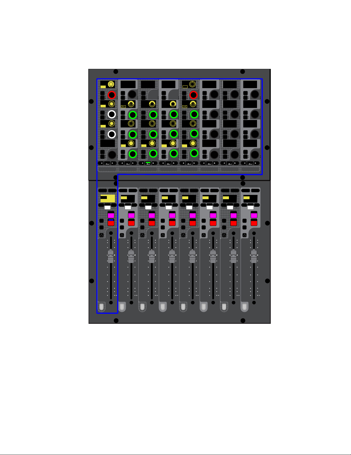
S6L Control Surface Overview 23
Channel Control Mode
Selecting a channel banked to a fader bank (or touching a parameter touch zone on a Channel Touch Module) enables Channel Con-
trol mode on the associated CKM. Channel Control mode provides comprehensive control over parameters such as EQ, Dynamics,
plug-ins, and Aux Sends for the currently selected channel. You can also create a custom set of controls for access to 32 assignable
parameters. See Adjusting Channel Parameters for more information.
S6L in EQ Channel Control mode (input channel EQ parameters shown)
MIXMIXMIXPLUG-INSDYNAMICSEQINPUTCHANNEL
In
Sel
In
Sel
In
Sel
In
Sel
In
Sel
In
Sel
In
Sel
In
Sel
In
Sel
In
Sel
In
Sel
In
Sel
In
Sel
In
Sel
In
Sel
In
Sel
In
Sel
In
Sel
In
Sel
In
Sel
In
Sel
In
Sel
In
Sel
In
Sel
In
Sel
In
Sel
In
Sel
In
Sel
In
Sel
In
Sel
In
Sel
In
Sel
60
40
30
20
10
5
0
6
12
60
40
30
20
10
5
0
6
12
Select
Solo
Select
Solo
Select
Solo
Select
Solo
Select
Solo
Select
Solo
Select
Solo
Select
Solo
BAS
Menu Safe
Mute
Y
X
Y
X
Y
X
Y
X
Y
X
Y
X
Y
X
Y
X
BAS
Menu Safe
Mute
BAS
Menu Safe
Mute
BAS
Menu Safe
Mute
BAS
Menu Safe
Mute
BAS
Menu Safe
Mute
BAS
Menu Safe
Mute
BAS
Menu Safe
Mute
60
40
30
20
10
5
0
6
12
60
40
30
20
10
5
0
6
12
60
40
30
20
10
5
0
6
12
60
40
30
20
10
5
0
6
12
60
40
30
20
10
5
0
6
12
60
40
30
20
10
5
0
6
12
60
30
21
15
9
3
0
3
9
15
60
30
21
15
9
3
0
3
9
15
60
30
21
15
9
3
0
3
9
15
60
30
21
15
9
3
0
3
9
15
60
30
21
15
9
3
0
3
9
15
60
30
21
15
9
3
0
3
9
15
60
30
21
15
9
3
0
3
9
15
60
30
21
15
9
3
0
3
9
15
Nom
0.0 dB
CH 1
Ch 1
IN IN IN IN
EQ In
Hi Gain
Hi Freq
HM Freq
LM Freq
Lo Freq
Lo Q
1.00
200 Hz 1.00 kHz 5.00 kHz
10.00 kHz
0.0 dB
0.0 dB
0.0 dB
0.0 dB
1.00 1.00 1.00
LM Q
HM Q
Hi Q
HM Gain
LM Gain
Lo Gain
CH 2
Ch 2
0.0 dB
CH 3
Ch 3
0.0 dB
CH 4
Ch 4
0.0 dB
CH 5
Ch 5
0.0 dB
CH 6
Ch 6
0.0 dB
CH 7
Ch 7
0.0 dB
CH 8
Ch 8
0.0 dB
LPF
HPF
80 Hz
20.00 kHz
MIXMIXMIXPLUG-INSDYNAMICSEQINPUTCHANNEL
In
Sel
In
Sel
In
Sel
In
Sel
In
Sel
In
Sel
In
Sel
In
Sel
In
Sel
In
Sel
In
Sel
In
Sel
In
Sel
In
Sel
In
Sel
In
Sel
In
Sel
In
Sel
In
Sel
In
Sel
In
Sel
In
Sel
In
Sel
In
Sel
In
Sel
In
Sel
In
Sel
In
Sel
In
Sel
In
Sel
In
Sel
In
Sel
IN IN IN IN
IN
IN
IN
IN
ON
ON
ON
ON
IN IN
IN IN
EQ In
Analog
Hi Gain
Hi Freq
HM Freq
LM Freq
Lo Freq
Lo Q
1.00
200 Hz 1.00 kHz 5.00 kHz
10.00 kHz
0.0 dB
0.0 dB
0.0 dB
0.0 dB
1.00 1.00 1.00
LM Q
HM Q
Hi Q
HM Gain
LM Gain
Lo Gain
LPF
HPF
80 Hz
20.00 kHz
IN IN
IN IN

S6L Control Surface Overview 24
Channel Control Functions
The Channel Control Function switches assign groups of parameters for the currently selected channel to the 32 encoders on the
CKM.
The labels below each switch indicate the type of parameters assigned to the CKM, as follows:
1 – CHANNEL
CHANNEL spills a variety of channel parameters such as input, EQ, and Dynamics parameters to the CKM, providing a default set
of utility parameters for the selected channel. You can also customize the parameters CHANNEL spills to the encoders. See
Using
the CHANNEL Function for more information.
2 – INPUT
INPUTS spills parameters such as gain, LPF, HPF, pad, pan, phantom power (48V), polarity, channel delay, channel safes, Direct
Out level, input source toggle, and Mains bus assign controls to the CKM. The available parameters depend on the type of channel
selected.
3 – EQ
For input channels, EQ spills the built-in 4-band EQ plus high- and low-pass filters to the CKM. For output channels, EQ spills
built-in 7-band EQ plus high- and low-pass filters to the CKM. If a graphic EQ (GEQ) is inserted on an output channel, pressing
a lit Parameter Bank switch spills GEQ parameter to the encoders.
4 – DYNAMICS
DYNAMICS spills the built-in Expander/Gate (input channels only) and Compressor/Limiter to the CKM.
5 – PLUG-INS
PLUG-INS assigns four Plug-In Selectors to the leftmost column of encoders, each of which corresponds to one of the four channel
Insert slots. Pressing a Plug-In Selector spills the parameters for that plug-in to the rest of the encoders on the CKM.
6 – MIX
The three MIX switches spill Aux, Group, or Matrix Mixer controls to the associated CKM. The type and number of Aux/Group-re-
lated parameters the MIX switches assign to the CKM is determined by the global Mix Bus configuration as set on the Options >
System page (see
System Configuration for more information).
The MIX switches spill the following parameters to the CKM, depending on the type of channel selected:
Aux Sends
When you select an input channel, the MIX switches spill Aux sends and/or Group bus assignment controls to the CKM.
You can assign the channel to Auxes/Groups, and adjust Aux send levels. Each MIX switch spills Aux Sends in sets of 32 channels,
as available. Groups are always accessed via MIX switch three (the rightmost MIX switch).
Members
When you select a Mains output, an Aux output, a Group output, or a VCA, the MIX switches spills the member channels
(the channels assigned to that bus or VCA) to the CKM, from which you can adjust the contributing levels of the member channels
to the selected bus or VCA. Each
MIX switch spills members in sets of 32 channels, as available.
Matrix Mixers
When you select a Matrix Mixer output, pressing any MIX switch assigns the available Matrix Mixer input controls
to the CKM, letting you turn Matrix Mixer inputs on/off and adjust Matrix Mixer input levels.
CKM Channel Control Function Switches
MIXMIXMIXPLUG-INSDYNAMICSEQINPUTCHANNEL
In
Sel
In
Sel
In
Sel
In
Sel
In
Sel
In
Sel
In
Sel
In
Sel
1 2 3 4 5 6 6 6
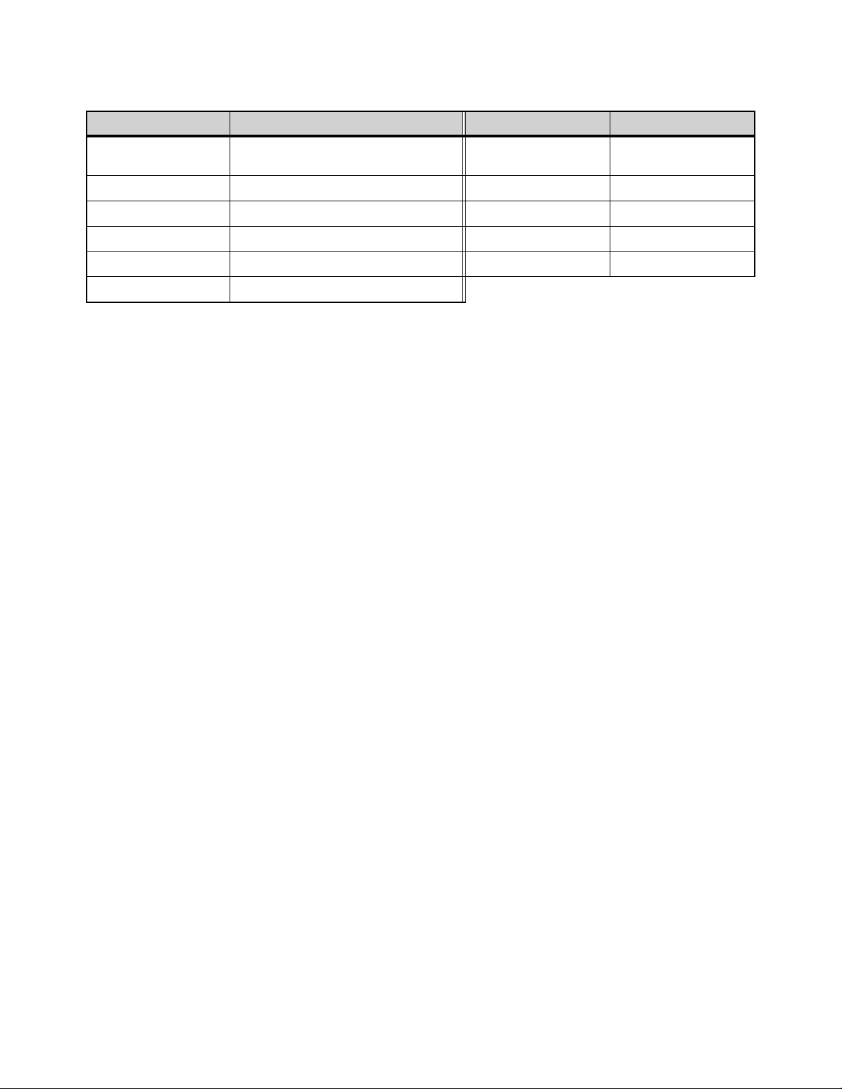
S6L Control Surface Overview 25
Encoder Color Coding
CKM encoders light in colors according to their function or parameter in all encoder modes, as follows:
* If you change the color of an Aux or Group output channel, the encoders for the sends to that output channel light in the assigned
color.
Function Color Parameter Color
Channel Parameters light in the color of the function
of which each parameter is a member
Group Assign Orange*
Input White Mains L-R Assign White (Red when In)
EQ Green Center/Mono Assign White (Red when In)
Comp/Lim Blue
Processor In/Out Red
Exp/Gate Yellow Plug-In Select Red
Aux Sends/Matrix Inputs Purple*
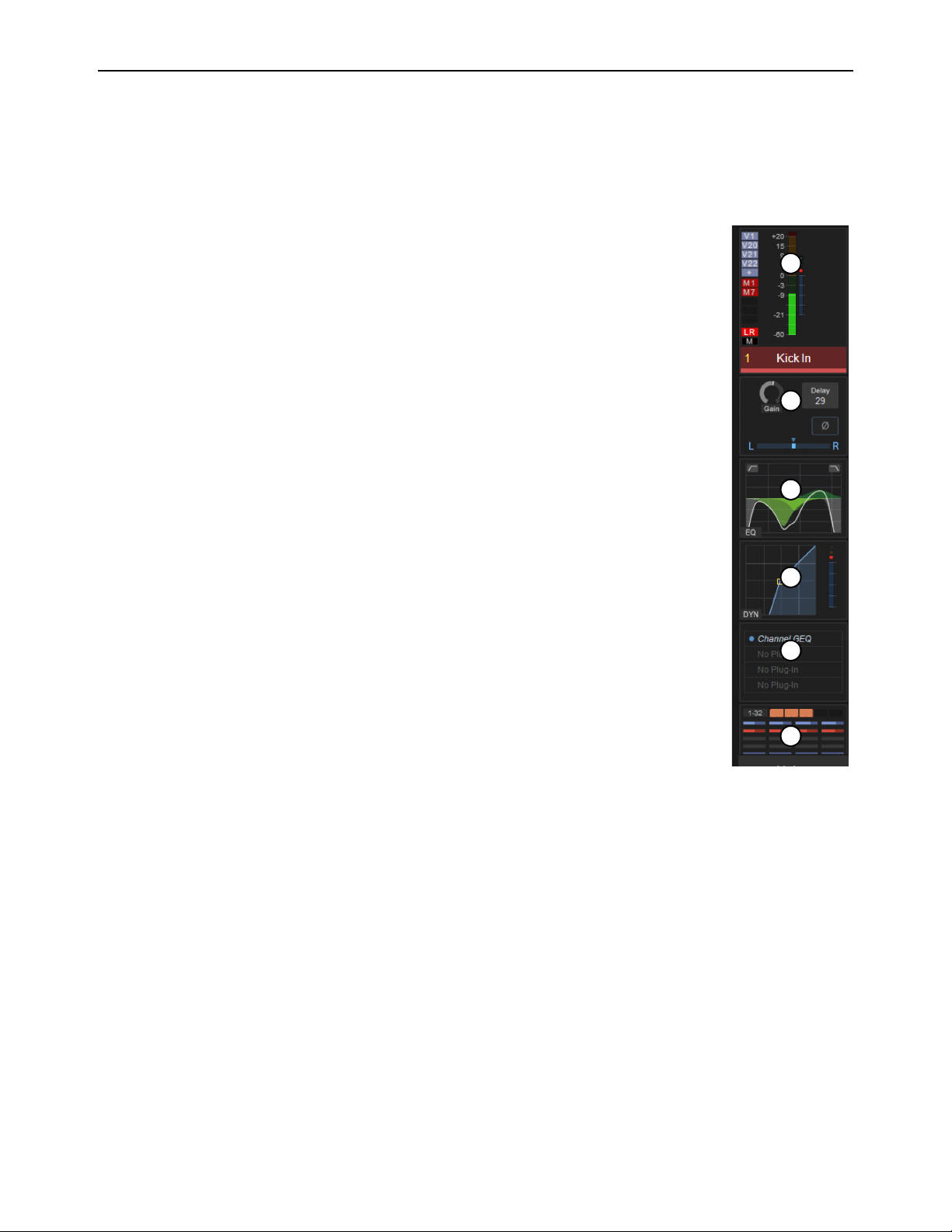
S6L Control Surface Overview 26
Channel Touch Module (CTM)
The S6L-32D provides three Channel Touch Modules (CTM), and the S6L-24D provides two CTMs. Each CTM is located above
a CKM, and is functionally associated with that CKM and the fader bank below it. The CTM provides a local view of the channels
banked to the associated fader bank. Using the CTM’s touch capabilities, you can select channel functions and spill those param-
eters to the associated CKM. The CTM provides two views, Meters view and Channel view.
Meters View
Meters view displays parameters for each channel vertically, like a “virtual channel strip.” Each strip is
composed of parameter touch zones that show the status of certain parameters for the associated chan-
nel. Parameters in each touch zone are lit when that parameter is on, and dimmed when off.
Touching a parameter touch zone simultaneously locally selects the corresponding channel and assigns
the touch zone’s parameters to the associated CKM in Channel Control mode. The active zone is indi-
cated by an orange border. Touching an active zone de-selects the corresponding channel. Each virtual
channel strip provides the following parameter touch zones:
1 – Meters and Assignments
This zone shows the associated channel’s channel number and name, and level and gain reduction for the
channel. Touching this zone changes the view on the CTM to a Channel view of the currently selected
channel.
To the left of the meters are (from top to bottom) VCA, Mute Group, and Mains bus assignment indica-
tors.
2 – Input
This zone shows a selection of input or output channel parameters. Touching this zone mirrors the func-
tion of the INPUT Channel Control Function switch.
3 – EQ
This zone shows the current EQ curve applied to the channel. Touching this zone mirrors the function
of the EQ Channel Control Function switch.
4 – Dynamics
This zone shows a composite dynamics graph for the channel. Touching this zone mirrors the function
of the DYNAMICS Channel Control Function switch.
5 – Plug-Ins
This zone shows the channel’s Inserts slots, and any plug-ins inserted in those slots. Touching this zone mirrors the function of the
PLUG-INS Channel Control Function switch.
6 – Aux Sends/Members/Matrix Mixer Inputs
This zone shows the following, depending on the type of channel banked to the corresponding channel strip:
Aux Sends and Groups
For input channels, this zone shows the channel’s Aux Sends in sets of 32, and Group bus assignments.
Each send is represented by a thermometer-style meter showing individual send level and on/off status (lit is on). Touching this
zone assigns the set of Aux sends indicated in the display (1–32, 33–64, 65–96, as available) to the associated CKM.
Members
This zone shows Aux output, Group output, Mains output, or VCA members (channels assigned to that bus or VCA),
their send levels, and on/off status in sets of 32. Touching this zone assigns the set of members indicated in the display (1–32,
33–64, 65–96, as available) to the CKM.
Matrix Mixers
For Matrix Mixers, this zone shows Matrix Mixer members (channels assigned to that Matrix Mixer), their input lev-
els, and on/off status. Touching this zone assigns the available Matrix Mixer input controls for the selected Matrix Mixer to the
CKM.
G1 G3 G8
1
3
2
6
4
5
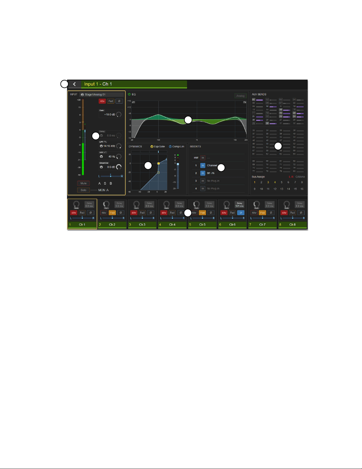
S6L Control Surface Overview 27
Channel View (CTM)
Touching the Meters in Meters views automatically selects that channel and replaces Meters view with Channel view. Channel
view provides a complete view of the selected channel’s parameters. Parameters in each touch zone are lit when that parameter is
on, and dimmed when off. As in Meters view, touching a touch zone assigns its associated parameters to the associated CKM in
Channel Control mode. Channel view also provides eight channel tiles, which you can touch to select, providing an uninterrupted
on-screen workflow.
1 – Input
This zone shows level and gain reduction meters, as well as a selection of other input parameters. Touching this zone assigns the
same parameters to the CKM as the CHANNEL Channel Control Function switch.
2 – EQ
This zone shows the current EQ curve applied to the channel by the built-in channel EQ, and its on/off state. For output channels
with a graphic EQ inserted, the current GEQ curve is also shown. Touching this zone mirrors the function of the EQ Channel Con-
trol Function switch.
3 – Dynamics
This zone shows a composite dynamics graph for the channel, and the dynamics processor(s) on/off state(s). Touching this zone
mirrors the function of the DYNAMICS Channel Control Function switch.
4 – Inserts
This zone shows the channel’s Inserts slots, and any plug-ins inserted in those slots, as well as the status of the channel’s hardware
insert. Touching this zone mirrors the function of the PLUG-INS Channel Control Function switch.
5 – Aux Sends/Members/Matrix Mixer
This zone provides an expanded version of the Aux Sends/Members/Matrix Mixer touch zone available in the Meters view. Three
touch zones are provided, mirroring the function of the three MIX Channel Control Function switches.
CTM Channel view (input channel shown)
1
3
4
2
5
6
7

S6L Control Surface Overview 28
6 – Channel Tiles
Channel view shows eight channel tiles at a time, mirroring the channels banked to the corresponding fader bank. Each channel tile
shows the channel number and name. Touching a channel tile selects that channel, and targets that channel for processing, mirror-
ing the function of the channel strip
Select switch. When you select a channel, the channel tile is bordered in orange.
7 – Back Button
This button returns the CTM to Meters view.
Master Live Module (MLM)
The Master Live Module is the “center section” of your S6L control surface, providing system-wide controls including fader bank-
ing controls, snapshot control, transport control for playback and recording, monitoring, Mute Groups, Function switches, and
more. The MLM also provides unique features such as two assignable Flex Faders, and two banks of Soft Keys, each featuring a
display and associated Soft Keys and navigation switches.
The MLM provides the following controls and indicators:
Master Live Module (MLM)
1 –
Global Modifiers
2 – Snapshot Controls
3 – System Functions
4 – Assignable Encoder
5 – Monitoring Section
6 – Flex Channels
7 – Fader Banking Controls
8 – Left Soft Keys
9 – Right Soft Keys
10 – CKM Control Switches
11 – Transport/Function Switches
VENUE | S6L
Solo Solo
Home
Config
VCAs
Outputs
Layouts
Inputs
Flip
Recall
Trans
F1 F2 F3 F4 F5
NEXT
PREV
Store
Y
X
Y
X
AFL
Dim
In
Sel
SNAPSHOTS
Talk
Back
Multi
Select
Encoder
Assign
Select
Clear
Tap
Tempo
Multi
Assgn
Default Fine
OK Cancel
Over
Write
Mix to
Mon
Solo
Clear
60
40
30
20
10
5
0
6
12
60
40
30
20
10
5
0
6
12
8All
Preview
ASSIGNABLE ENCODER MONITORING
Push A/BHold SIP
SHIFT
ALT
CTRL
ESC
Mute Mute
A
B
Nom
30
21
15
9
3
0
3
9
15
30
21
15
9
3
0
3
9
15
Inputs/Outputs
Next
Global Controls
0.0 dB
L
Left
0.0 dB
Kick
Mute Group 1
Mute Group
Function KeysMute Group 2
Mute Group 3
Mute Group 4
Mute Group 5
Mute Group 6
M1
M2
M3
M4
M5
M6
001/011
reset all inputs
0.0 dB
CH 1
Kick
Ch 1-16
1-16
Aux 1-8
1-8
Aux 9-16
Aux 17-24
Aux 25-32
25-32
VCA 1-8
1-8
VCA 9-16
9-16
Ch 17-32
17-32 9-16
Ch 33-48
33-48 17-24
Ch 49-64
49-64
Ch 65-80
65-80
Ch 81-96
81-96
S1Cu2
001 3
P:S1C1
N:S1C3
S1Cu3
S1Cu2
1
10
2
7
3 54
6
2
98
11
S6L Control Surface Overview 29
Global Modifiers
Multi-Select (Shift)
Multi-Select lets you select or attention multiple channels, and then apply an action to all selected/at-
tentioned channels for batch routing and assignment. For more information see Selecting/Attentioning
Multiple Channels (Multi-Select). You can also use Multi-Select to select multiple consecutive items
in the Snapshots list.
Multi-Assign
Multi-Assign Lets you quickly assign multiple input channels to a selected bus or VCA. See Assigning Channels Using
Multi-Assign.
Default (Alt)
Default provides a quick way to reset a control to its default setting (or “zero” the setting), such as resetting a fader to 0 dB.
To reset a fader to 0 dB:
Hold Default and do any of the following on the channel strip for the channel you want to reset:
• Touch the fader.
• Press Select or Attention.
To reset a single parameter:
Hold Default and press the encoder for the parameter you want to reset, where applicable.
To reset all parameters of a built-in channel EQ, Expander/Gate, or Compressor/Limiter processor:
Hold Default and do the following:
• Press the EQ In encoder to reset the EQ.
• Press the E/G In encoder to reset the Expander/Gate.
• Press the C/L In encoder to reset the built-in Compressor/Limiter.
To reset an Aux send to 0 dB and turn the send off:
Hold Default and press the encoder for the Aux send you want to reset.
Fine (Ctrl)
Fine lets you adjust controls (except for faders) on the console or on-screen with maximum resolution. For example, if by default
a control adjusts a parameter in units of 1 dB, the Fine switch allows adjustment in units of 0.1 dB.
You can also use Fine to select multiple non-consecutive items in the Snapshots list.
To adjust a control with fine resolution:
Press and hold Fine while moving a control. The display associated with the adjusted control will show the values change at the
corresponding resolution.
To Multi-Select on the external screen, press the Shift key on the keyboard and select
the items on-screen.
To reset a parameter on the external screen, press the Alt key on the keyboard and select the parameter on-screen.
To adjust a control with fine resolution on the external screen, press Ctrl on the keyboard and adjust the parameter on-screen.
Multi
Select
Multi
Assgn
Default Fine
OK Cancel
SHIFT
ALT
CTRL
ESC

S6L Control Surface Overview 30
Momentary and Latching Modes
Fine supports momentary and latching operation.
Momentary
In momentary mode, Fine stays in effect for as long as you hold down that modifier switch.
Latching
In latching mode, Fine stays in effect until you explicitly clear its active state.
To use Fine in momentary mode:
1 Press and hold Fine.
2 Adjust a channel, parameter, or processor.
3 Release Fine.
To use Fine in latching mode:
1 Double-press Fine. The switch LED lights.
2 Select or adjust one or more channels, parameters, or processors.
3 Press Fine again to exit latching mode.
OK
OK confirms the current operation, such as confirming assignments made in Multi-Select mode, or dismisses dialogs such as the
Waiting for Device dialog.
Cancel (Esc)
Cancel exits the current operation, such as exiting Multi-Select mod. Holding cancel also unlocks the system if it has been locked.
Snapshot Controls
The S6L control surface provides Snapshot controls in two locations on the MLM: in the Snapshots section and the Prev/Next
switches, below the right-hand MLM display. For more information on using Snapshots, see
Snapshots.
Snapshots Section
You can target (select), store, recall, and preview snapshots using the controls in this section.
Select Encoder and Displays
Turning the select encoder scrolls through and selects the targeted snapshot in the Snapshots list. The
displays show the number and name of the currently targeted snapshot.
Store
Saves the current state of all console parameters in the targeted snapshot. This switch mirrors the Store button on the Snap-
shots page.
Recall
Loads the targeted snapshot. This switch mirrors the Recall button on the Snapshots page.
Preview
Enables Snapshot Preview mode, and mirrors the Preview button on the Snapshots page. Preview mode lets you recall,
store and edit snapshots without affecting the current mix. See Preview Mode for more information.
Snapshots section
VENUE | S6L
Recall
Store
SNAPSHOTS
Preview
001/011
reset all inputs
S1Cu2
001 3
P:S1C1
N:S1C3
S1Cu3
S1Cu2
S6L Control Surface Overview 31
Prev/Next Switches
These switches instantly recall the previous or next snapshot in the Snapshots list. The switches are lit when there is a previous or
next snapshot to recall.
System Functions
The switches in this section provide control over a variety of system-wide functions.
Home
Home lets you quickly return the control surface and all screens to their default states and view, but does not reset any parameters,
as follows:
• Channel 1 is attentioned
• Channels are banked to the default split banking mode (where inputs are banked to outside fader banks and outputs are banked
to the center fader bank, under the MLM),
• All channels are deselected and all CKMs revert to Channel Strip mode
• All CTMs show Meters view
• The MTS shows the Universe > Inputs view
• The external screen shows the Inputs page
Config
Config toggles the system between Config and Show modes. Use Config mode when configuring your system (for example, when
changing Bus configurations). Use Show mode during performances. For more information see Enabling Config Mode. Config
lights when Config mode is enabled.
Over Write
The Over Write switch on the MLM is equivalent to the Overwrite button on the Save tab of the Filing page. When pressed, a di-
alog is displayed asking you to confirm that you want to overwrite the currently targeted Show file.
Talkback
Talkback turns the Talkback circuit on, and operates in momentary (press-and-hold) and latching (double-press) modes.
Assignable Encoder
This encoder and associated display are reserved for future use.
Prev/Next Snapshot switches
System Function switches
In previous versions of VENUE software, pressing Home would also reset the Flex Channels to their default assignments
(attentioned channel and Mains, as defined in Options > Interaction).
Talkback is routed using the Options > Misc page of the external screen. See Talkback for more information.
Recall
Store
SNAPSHOTS
NEXT
PREV
Home Config
Talk
Back
Over
Write
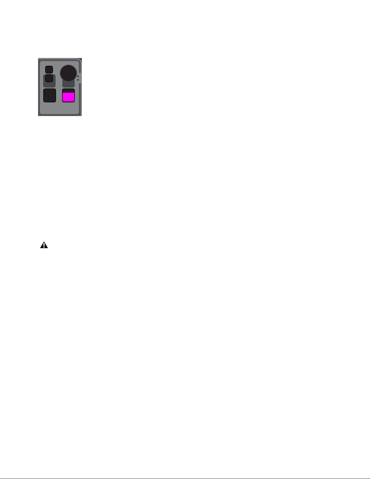
S6L Control Surface Overview 32
Monitoring Section
The S6L system provides two discrete Monitor buses (Monitor bus A and B). The Monitoring section provide controls for the cur-
rently targeted Monitor bus.
Monitoring Encoder
The monitoring encoder lets you target a Monitor bus for control and provides level control for the targeted Monitor bus, as follows:
Push the encoder to toggle the controls in the Monitor section between Monitor bus A and B. The A or B LED lights to indicate
the currently targeted Monitor bus.
Rotate the encoder to adjust the level for the targeted Monitor bus.
Dim
This switch is reserved for future use.
AFL/Hold SIP
AFL enables after-fader-listen (AFL) mode on the currently targeted Monitor bus.
Pressing and holding AFL temporarily engages solo-in-place (SIP) mode.
Mix to Monitors
Sends the Main mix signal to the targeted Monitor bus. When enabled (lit), the Main mix is present in the headphones (or other de-
vice connected to a hardware output to which the Monitor bus is routed) whenever channels are not soloed.
Solo Clear
Solo Clear Flashes when one or more channels are soloed, and does the following when pressed:
• A single press clears any solos on the currently targeted monitor bus.
• A double press clears all soloed channels.
Monitoring section
SIP mode interrupts audio on the Main bus. Do not engage SIP during a performance.
AFL
Dim
Mix to
Mon
Solo
Clear
MONITORING
Push A/BHold SIP
A
B
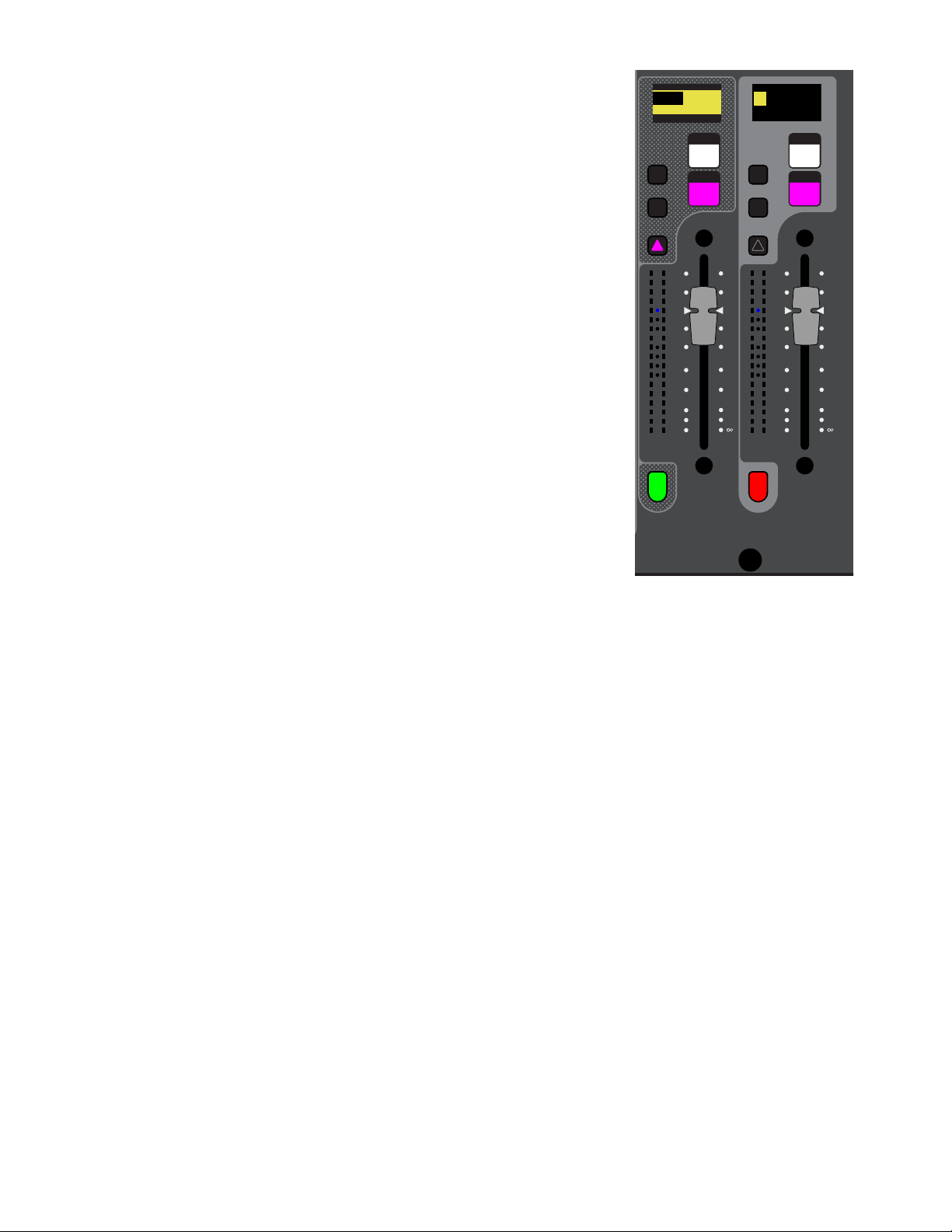
S6L Control Surface Overview 33
Flex Channels
Two Flex Channels provide access to channels irrespective of the active fader layout or
bank. You can configure the Flex Channels in the Fader Configuration section of the Op-
tions > Interaction page of the external screen. See Fader Configuration information
on customizing the Flex Channels.
By default, enabling a channel’s Attention switch assigns that channel to Flex Channel
1 left), and a single fader controlling Mains Left and Right is assigned to Flex Channel
2 (right).
Each Flex Channel provides the following features:
Display
Shows the channel number and name of the currently assigned channel.
Mute
Mutes the currently assigned channel, and follows global Mute settings.
Solo
Solos the currently assigned channel, and follows global Solo settings.
X and Y Switches
Mirror the functionality of the attentioned channel’s X and Y
switches.
Attention
Mirrors the functionality of the Attention switch on the channel strips.
Fader
Adjusts the level for the currently assigned channel.
Channel and Dynamics Meters
Show the channel level and gain reduction for the as-
signed channel via 18-segment and 4-segment LED ladders, respectively.
Channel Color Switch
Mirrors the function of the Channel Color switch for the currently
assigned channel, and lights according to the channel’s assigned color-coding.
Latching a Channel to a Flex Channel
When a Flex Channel is configured to control an attentioned channel, you can “latch” the
currently attentioned channel to the respective Flex Channel. When you latch a channel
to a Flex Channel, attentioning another channel does not change the assignment of the Flex Channel, letting you keep constant con-
trol over your most important channel.
To latch a channel to the Flex Channel from the control surface:
Double-press the channel strip Attention switch for the channel you want to latch to the Flex Channel.
To latch a channel to the Flex Channel from the external screen:
1 Go to the Inputs or Outputs page.
2 Touch and hold (right-click) a fader strip.
3 Choose Latch <“channel name/”number>.
To unlatch the Flex Channel:
Double-press the latched channel’s Attention switch. Pressing Attention on another channel now assigns that channel to the
Flex Channel.
– or –
From the external screen, touch and hold the latched channel and choose Unlatch <“channel name/”number>.
Solo Solo
Y
X
Y
X
60
40
30
20
10
5
0
6
12
60
40
30
20
10
5
0
6
12
Mute Mute
A
B
Nom
30
21
15
9
3
0
3
9
15
30
21
15
9
3
0
3
9
15
0.0 dB
L
Left
0.0 dB
Kick
0.0 dB
CH 1
Kick
Flex Channels 1 (left) and 2 (right)
showing default assignments
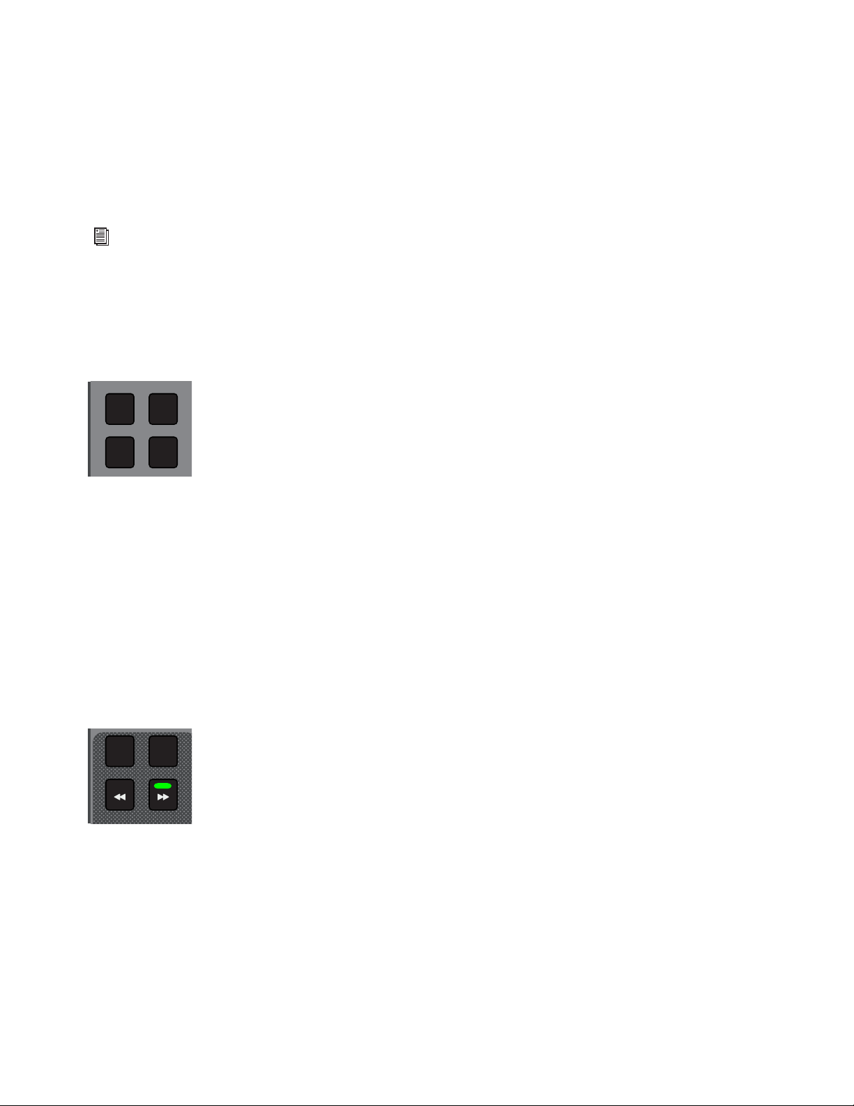
S6L Control Surface Overview 34
Fader Banking Controls
S6L lets you bank channels to faders in a variety of ways. By default, channels are banked to S6L faders in a “split” banking con-
figuration. Input channels are banked sequentially to the fader banks below CKMs and CTMs, and output channels are banked to
the fader bank below the MLM. The Left Soft Keys display shows pre-defined banks of channels, which you can bank to faders us-
ing the associated Soft Keys.
The two groups of switches in this section, the Fader Bank Mode switches and the Horizontal Banking switches, provide an alter-
nate banking mode that let you bank only the selected channel types to all the faders on the control surface, then nudge them left
or right.
Fader Bank Mode Switches
The Fader Bank Mode switches (Layouts, VCAs, Inputs, and Outputs) enable Fader Bank Mode, which banks only those re-
spective channel types to all the faders of the control surface (except Flex Channels). The Left Soft Keys display shows banks of
channels containing only the types of channels provided by the selected channel type, which you can select by pressing a corre-
sponding Soft Key. Deselecting the active Fader Banking Mode switch returns the faders to the most recent split banking config-
uration.
Each switch lets you bank only the following channel types to the faders using the associated Soft Keys:
Layouts
Banks a custom fader configuration (“Layout”) to all faders on the S6L control surface. See User Layouts for more in-
formation on creating and using Layouts.
VCAs Banks only VCAs to all faders.
Inputs
Banks only input channels to all faders.
Outputs
Banks only output channels to all faders.
Horizontal Banking Switches
These switches provide horizontal banking of channels (“nudging”), and are available only when you have enabled one of the Fader
Banking Mode switches.
<<, >>
Nudges channels to the left or right by one channel.
All
When All is enabled, the << and >> switches move all channels 24 or 32 channels to the right or left, depending on your control
surface. For example, if input channels 1–24 are banked to all faders on an S6L-24D, pressing >> when All is enabled banks input
channels 25–48 to the faders.
8
When 8 is enabled, the << and >> switches move all channels eight channels (one bank) to the right or left. For example, if input
channels 1–24 are banked to all faders on an S6L-24D, pressing >> when 8 is enabled banks input channels 9-16 to the left fader
bank, input channels 17–24 to the center bank, and channels 25–32 to the right bank.
See
Banking Channels on the S6L Control Surface or more information.
Fader Banking Mode switches
Fader Banking Navigation switches
VCAs
Outputs
Layouts
Inputs
8All

S6L Control Surface Overview 35
Left Soft Keys
Fader Banking Controls
The Left Soft Keys provide access to pre-defined fader bank layouts, as well as custom layouts. The display shows the available
fader bank layouts across multiple pages. Pressing a corresponding Soft Key banks the channels indicated in the display to the fad-
ers. The available fader layouts vary depending on whether or not a Fader Banking Mode switch is enabled.
Right Soft Keys
Mute Groups, Functions, and GEQ on Faders
The Right Soft Keys provide access to Mute Groups, programmable Functions, and GEQ on Faders. Pressing a corresponding Soft
Key enables that Mute Group or Function.
Mute Groups
The S6L system provides 24 Mute Groups, which let you mute groups of channels with the press of a single Soft Key. Add channels
to Mute Groups using the Mutes Channel Type button on the Master Touch Screen (MTS).
Functions
Customizable Functions let you control a wide range of console parameters with the press of a Soft Key. Assign actions to Func-
tions using events, available on the Control > Events tab of the external VENUE software screen.
GEQ on Faders
When GEQs are assigned to channels, they can be banked to faders with the press of a Soft Key.
CKM Control Switches
These switches primarily control functions associated with the CKMs.
Encoder Assign
This switch lets you specify a custom set of four parameters to display across rows of CKM controls in Channel Strip mode.
Flip
Flip to Faders
Flip enables Flip to Faders mode on the control surface for input channels. Flip to Faders lets you flip any Channel Strip mode pa-
rameter to the faders on the control surface, temporarily replacing the channel level control with the currently targeted parameter.
See
Flipping Parameters to Faders (Flip to Faders Mode).
See Muting and Mute Groups for more information.
See
Events for more information.
CKM control switches
See
Encoder Assign Mode for more information.
You can also flip Aux sends to faders using Sends on Faders mode. When Sends on Faders is enabled, soloing an Aux output
assigns Aux Send level controls for the soloed Aux output to the faders. See Adjusting Aux Sends on Faders (Sends on
Faders Mode).
Flip
Encoder
Assign
Select
Clear
Tap
Tempo
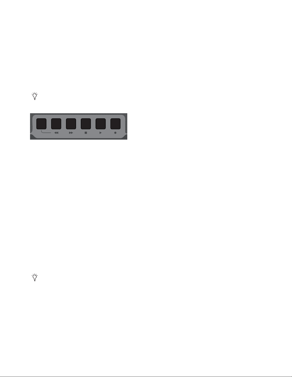
S6L Control Surface Overview 36
Select Clear
Clears all selected channels and returns all CKMs to Channel Strip mode.
Tap Tempo
Sets the system tempo for use as a beat clock for delay and echo plug-ins that support Tempo Sync. The switch blinks in time with
the system tempo. For more information see Tap Tempo for Plug-ins.
Transport/Function Switches
These dual-function switches provide dedicated switches to control the Pro Tools Transport, as well as programmable function
switches that you can use to control a wide range of system parameters using events (see Events for more information).
The following switches are provided:
Trans
Toggles the F1–F5 switches between control of events and the Pro Tools Transport.
When unlit, by default the switches target pages on the external screen, as follows:
F1
Targets the Inputs page.
F2
Targets the Outputs page.
F3
Targets the Snapshots page.
F4
Targets the Plug-Ins page.
F5
Targets the Options page.
When Trans is lit, Pro Tools Transport controls are active, and provide the following functionality:
F1
Is reserved for future use.
F2
Is reserved for future use.
F3
Stops the Pro Tools Transport.
F4
Initiates playback in the Pro Tools Transport.
F5
Arms the Pro Tools transport and initiates recording.
To access all Function Keys:
1 In the right Soft Keys on the MLM, press the switch for Function Keys.
The first 12 currently assigned Function switches appear in the Soft Keys.
2 To navigate to Functions 13–24, press the Soft Key below Next.
You must enable VENUE Link on your S6L system and in Pro Tools to use the transport controls. See the S6L Live Recording
Guide.pdf for more information.
Transport controls
Up to 24 Function switches are available; F1–F5 in the Transport/Function Keys section, and all 24 in the right Soft Keys of the
MLM. To see the default (factory) Function key assignments, use the
Clear Console command. All available Function Keys can
be assigned and reassigned using Events.
Trans
F1 F2 F3 F4 F5
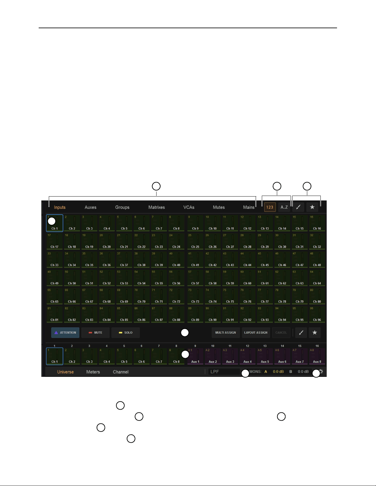
S6L Control Surface Overview 37
Master Touch Screen (MTS)
All S6L control surface models (except the S6L-16C) feature a Master Touch Screen (MTS). Located above the Master Live Mod-
ule, the MTS provides a global view of S6L system channels, a Meters view, and can also provide a targeted view of the currently
attentioned channel. Using the touch capabilities of the MTS, you can also perform channel actions such as attentioning, soloing
and muting channels irrespective of the active fader layout or bank, as well as assign channels to custom fader layouts.
The MTS provides three views, the Universe view, Meters view, and Channel view. With S6L-16C, Universe view and essential
connection and configuration screens are provided on the external screen.
Universe View
Universe view displays a bank of up to 96 channel tiles at a time in six rows of 16 channels each. You can navigate to additional
channel tiles by swiping vertically. You can attention channels, and enable or disable solo and mute from the Universe view, as well
as target different channel types to the screen. Universe view also lets you assign channels to layouts, “favorite” channels and sort
channels that appear on the screen by number, name, color, and favorite status. Other functions are available depending on the cur-
rent view.
To access Universe view:
Tap Universe at the bottom of the MTS so it lights orange.
Basics of Using the Universe View
Touch a Channel Type button to show those channels.
Touch a Channel Tile Function button so it lights to activate that function for the Channel Tiles .
Touch a Channel Tile to Attention, Mute, or Solo that channel, depending on the active Channel Tile Function button.
Touch a Channel Tile Filter button to order channels numerically by channel number, or alphabetically by channel name.
MTS Universe view showing Inputs
7
1
6
4
5
2 3
8
2
5
1
1
3

S6L Control Surface Overview 38
The Universe view provides the following on-screen elements. Not all elements are available in all Universe views.
1 – Channel Tile
Each channel on your system has a corresponding channel tile in the Universe. Each channel tile shows the channel’s number and
name, as well as its current attention, mute solo, and favorite status. A level meter is also provided.
Touching a channel tile engages the currently selected track function for that track, as determined by the Track Function buttons.
Double-tapping a channel tile targets that channel in the MTS Channel view.
To access more channel tiles than are shown, swipe vertically. Depending on the channel type selected, more channels may or
may not be available.
2 – Channel Type Buttons
Touching one of these buttons shows only the channel tiles for the selected channel type. Only one of these buttons can be selected
at a time, and lights orange when active.
3 – Channel Tile Sort By Buttons
These buttons sort the channel tiles in the MTS Universe. One of these buttons is active at all times. Touching one of these buttons
sorts channels as follows:
123
When enabled, orders channel tiles by number.
A...Z
When enabled, orders channel tiles alphabetically.
4 – Channel Tile Filters
These buttons filter the channels tiles shown in the MTS. Touching one of these buttons so it lights sorts the channel tiles in the
MTS Universe as follows:
Channel Color Filter (Brush)
When enabled, shows channel tiles according to the color selected in the pop-up. Channels have de-
fault color-codings, which you can change. For more information see Color-Coding Channel from the Universe View.
Favorites Filter (Star)
When enabled, shows only the channel tiles you have designated as favorites using the Star (Favorite As-
sign) Track Function button.
5 – Channel Tile Function Buttons
Channel Tile Function buttons determine what happens when you touch a track tile. When you select a Channel Tile Function but-
ton, touching a track tile engages the selected function for that track, as follows:
Attention
Mirrors the function of the channel strip Attention switch.
Mute
Mirrors the function of the channel strip Mute switch.
Solo
Mirrors the function of the channel strip Solo switch, and adheres to global Solo settings as defined in the Options > Buses
page of the external screen.
Spill
Lets you rapidly access channels assigned to an Aux or Group output bus, Matrix, or VCA by spilling them to faders.
Multi-Assign
Mirrors the functionality of the Multi-Assign switch on the MLM and in the external screen.
Layout Assign
Lets you assign channels to a custom fader bank configuration called a “Layout.” See User Layouts for more in-
formation on creating and using Layouts.
Channel Color Assign (Brush)
Lets you color code channels directly from the MTS. See Color-Coding Channel from the Uni-
verse View.
Favorites Assign (Star)
Lets you designate one or more channels as favorites, which you can then filter in the MTS Universe view
using the Favorite (Star icon) Channel Filter button.
You can also color-code channels in the external VENUE software (see Color-Coding Channels from the External
Screen).

S6L Control Surface Overview 39
To favorite a channel:
1 Tap the Favorite Assign (Star icon) Track Function button on the MTS so it lights.
2 Tap any channel tiles you want to favorite. A star appears in each channel tile that is designated as a favorite.
3 When finished, touch the Favorite Assign button again so it is unlit, or touch another Function Assign button.
To show only favorite channel tiles in the MTS:
1 Assign the desired channels to the channel tiles by touching a Channel Type button.
2 Tap the Favorite (Star icon) Channel Tile Filter button.
6 – Universe Scroller
The Universe Scroller shows channel tiles for the channels currently banked to the S6L channel strips. Swipe horizontally to view
additional channels.
7 – Control Surface Configuration (Gear Icon)
The gear icon provides access to the Control Surface Configuration page, where you can view detailed information about modules
and adjust LED brightness. For more information see Troubleshooting.
8 – Mons A and B Level Indicators
These indicators show the Monitoring output levels of Monitor Bus A and Monitor Bus B, and change when the Monitoring en-
coder is adjusted, depending on the Monitor bus currently targeted by the Monitoring encoder.
Color-Coding Channel from the Universe View
You can color-code channels in the Universe view, then sort channel tiles by color.
To color-code a channel from the Universe view:
1 Tap Universe.
2 Tap the Brush Track Function button so it lights.
3 Tap the desired color in the pop-up.
4 Assign the desired channels to the channel tiles by touching a Channel Type button.
5 Tap the channel tiles you want to color code in the selected color.
6 When finished color-coding, touch the Brush Track Function button so it is unlit.
The color coding is reflected in the Universe view channel tiles; on the CTM for the color-coded channels; on the Channel Color
switch; on the CKM encoders for Aux Sends, Matrix input controls, Group assignment controls, and Mains assignment control;
and on the fader strips and the Aux Sends section on the external screen.
To show only the channel tiles that share a color-coding:
1 Assign the desired channels to the channel tiles by touching a Channel Type button.
2 Tap the Brush Channel Tile Filter button.
3 Tap the desired color in the pop-up.
4 To remove the color-code filter, touch the Brush Channel Tile Filter button so it is unlit.
With S6L-16C the Control Surface Configuration page is accessed on the external screen by choosing Options > Configuration.
You can also color-code channels from the external screen. See
Color-Coding Channels from the External Screen for
more information.
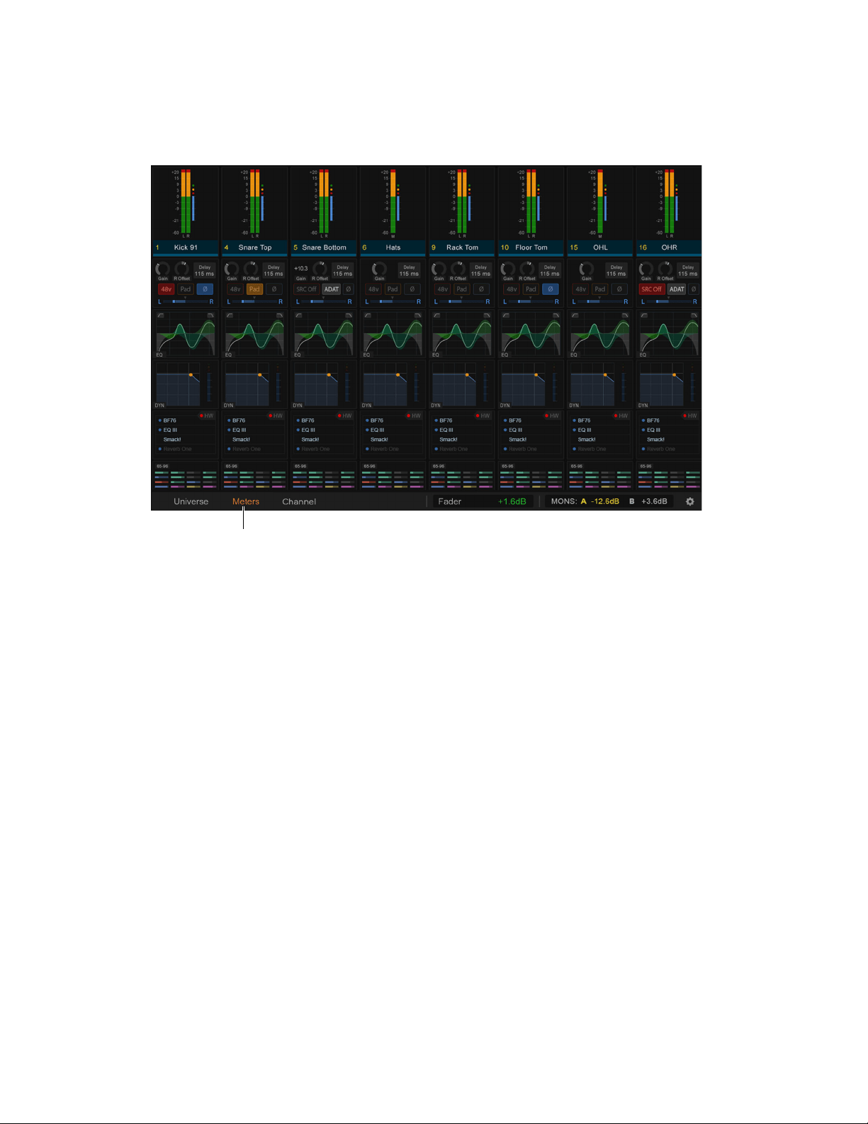
S6L Control Surface Overview 40
Meters View (MTS)
The MTS provides a Meters view that looks and operates just like CTM Meters View. Meters view provides a local view of the
channels banked to the faders below the MLM.
• Tapping a Meter switches the MTS to the Channel view for the corresponding channel. Tapping < returns to Meters view.
S6L-24C Meters View on MTS
When the MTS is in Meters View it shows the channels on the faders directly below it (OLEDs on those strips show a Selection
outline). By default, Meters view on the 24C follows the Selected channel.
You can change this behavior to instead have the MTS Meters view be associated with whichever strips are banked below the MTS.
To configure Meters Follow Selection:
1 On the external screen go to Options > Interaction.
2 Enable or disable the Meters Follow Selection setting.
• When enabled, Meters View on the MTS associates with the bank of channels that has a channel selected locally.
• When not enabled, Meters View associates with the faders directly below the MTS.
Meters view on the MTS
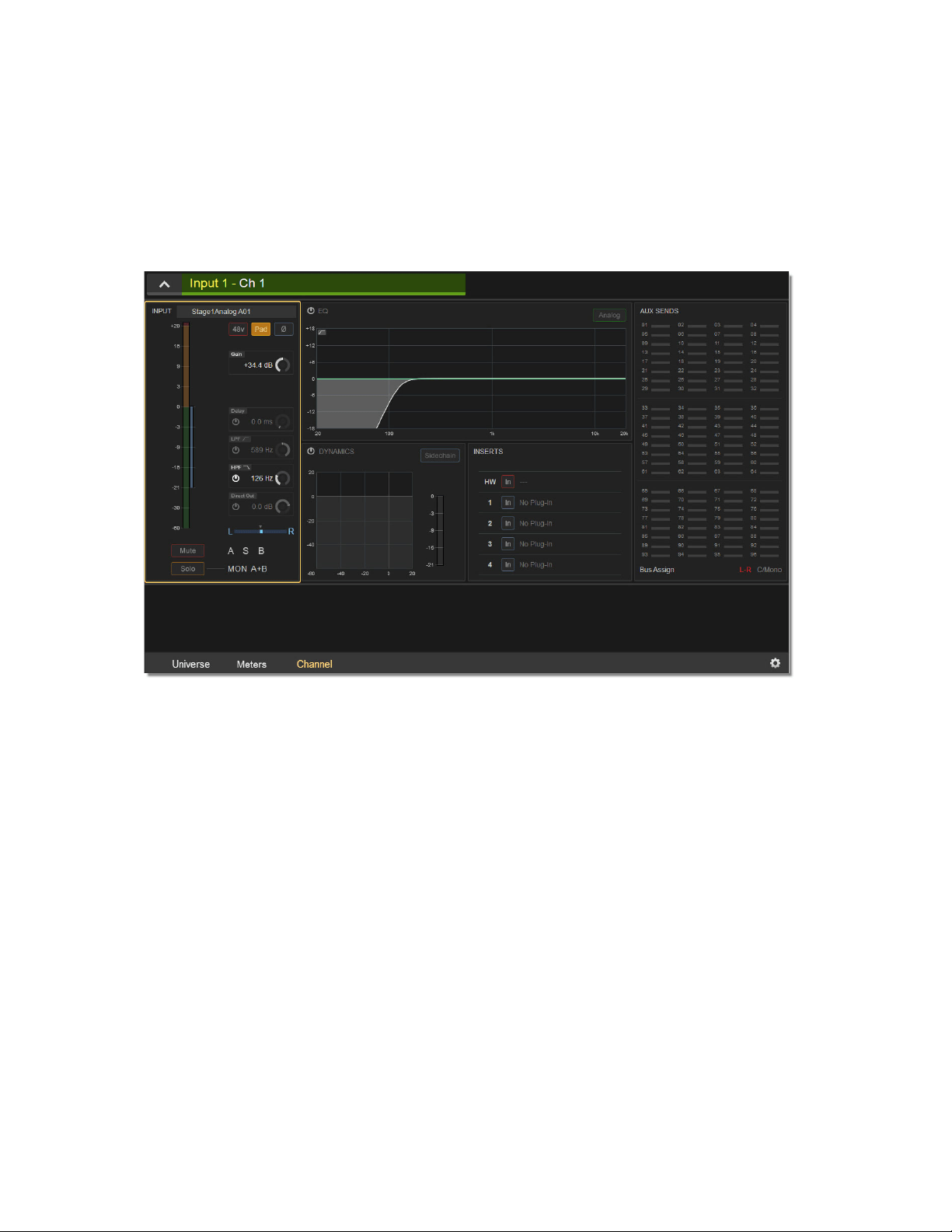
S6L Control Surface Overview 41
Channel View (MTS)
MTS Channel view provides a detailed view of the attentioned channel’s parameters, and provides most of the same on-screen el-
ements as the Channel View (CTM) on the CTM.
The MTS channel view provides visual feedback for the attentioned channel’s parameters but, unlike the CTM Channel view, pro-
vides no touch zones for parameter control.
To access Channel view:
Tap Channel at the bottom of the MTS so it lights orange.
MTS Channel view
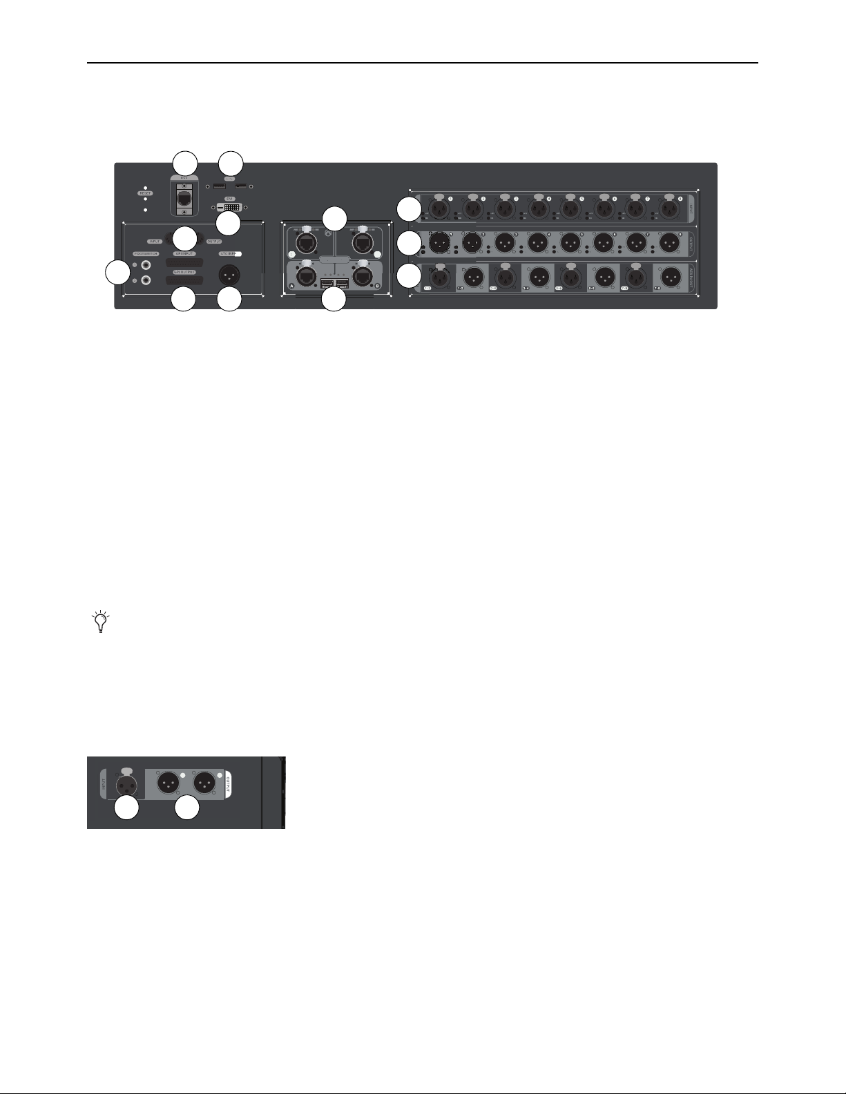
S6L Control Surface Overview 42
S6L Control Surface Connections
The S6L-32D, S6L-24D, and S6L-24C, and S6L-16C all have the same network and ancillary connections. Audio connections are
identical on all except S6L-16C, as noted below.
Audio Connections
(S6L-32D/24D/24C)
S6L control surface audio I/O is assigned to VENUE system channels using the Patchbay, under the Console tab. If using Local 16
I/O, its inputs and outputs appear in the Patchbay under the Local tab.
• To assign inputs, see
Patching Input Sources to Input Channels.
• To assign outputs, see
Patching Output Channels to Hardware Outputs.
1 – Analog Mic/Line Inputs 1–8 (8 XLR Connectors)
Each input features signal and 48V phantom power LEDs, which light when a signal is present and 48V is applied, respectively.
2 – Analog Outputs 1–8 (8 XLR Connectors)
Each output features an LED that lights when a signal is present on the output, and a mute LED indicator that lights when the output
is muted. Outputs auto-mute when the system is powered on.
3 – AES Digital I/O (4 x stereo inputs, 4 x stereo outputs)
Inputs feature Sample Rate Conversion, which converts signals to the current sample rate of the system. See
Synchronization.
S6L-16C Audio Connections
S6L-16C control surface audio includes the following:
1 – Analog Mic/Line Input (XLR Connector)
2 – Analog Outputs 1–2 (2 XLR Connectors)
S6L control surface back panel (S6L-32D/24D/24C)
You can mute all the outputs on the S6L control surface at once from the Devices page of the external VENUE software screen.
See
Muting Stage and S6L Control Surface Outputs
S6L-16C control surface back panel audio connectors
5
8
7
2
3
6
4
9
1
10
11 12
1 2
21

S6L Control Surface Overview 43
Network Connections
3 – Network A and B
(Two etherCON RJ-45 Ports, and two SFP Fiber-Optic Ports)
The S6L control surface provides two connections (A and B) to connect the control surface to other S6L system components. Each
connection provides an RJ-45 with etherCON connector for copper connections and an SFP transceiver module-compatible fi-
ber-optic port for fiber-optic connections, as follows:
Port A
Connects to port B on the Master 1 Network card (bottom Network card) of the E6L engine.
Port B
Connects to port A on the last Stage 64 in a configuration, providing the redundant audio network connection for the Ring
Network 1.
4 – Network Ports C and D
(Two RJ-45 Ports with etherCON Connectors)
These ports provide AVB audio network connections to system components, as follows:
Port C (Pro Tools)
Connect to a compatible Pro Tools system (or other DAW) using a supported audio network cable for integrated
Pro Tools recording, playback and interoperability. This connection supports up to 128 channels of simultaneous recording and
playback between S6L and Pro Tools. See Pro Tools Recording and Playback for more information.
Port D
Connects to a secondary compatible Pro Tools system. If only using a single Pro Tools system, use Port C.
5 – ECx Port
Connect a wireless router or a computer to this port to enable ECx remote control, and to be able to use VENUE | On-stage and
VENUE | Function Pad apps for iOS. This port does not provide AVB audio network connections. For more information see the
ECx Ethernet Control Guide
., VENUE On-Stage.pdf, or VENUE Function Pad.pdf.
Control and Ancillary
6 – USB Ports
(Two USB 3.0 ports)
Connect USB peripherals such as external touch screen USB, keyboards, bluetooth transmitters for wireless keyboards and mice,
flash drives (for data transfer), and iLoks (for plug-in authorizations) to these ports.
7 – DVI-D Display Connector
Connect a DVI-D compatible Full HD display with 1920 x 1080 minimum resolution (21.5-inch or greater touch display recom-
mended) to this port to view the external screen.
8 – MIDI In and Out Ports
Each MIDI port provides 16 channels of MIDI input and 16 channels of MIDI output to and from the system. You can send and
receive snapshot MIDI messages, receive MIDI Time Code (MTC) from external devices, and send MTC to external devices. See
Synchronization for more information.
Only one type of connection (copper or fiber-optic) can be active at a time for each port. Never connect both copper and fiber
to the same port (A or B).
For more information on audio network connections, see the VENUE S6L Installation Guide.pdf.
Each Network port has Act and Sig LEDs to indicate network status. See.Network Port Act and Sig LEDs for more infor-
mation.
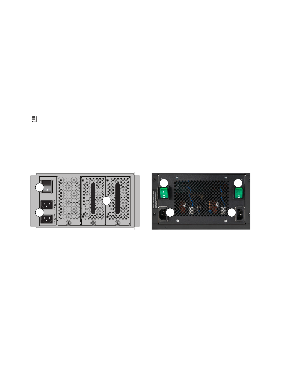
S6L Control Surface Overview 44
9 – Footswitch Connectors 1–2
(2 1/4-inch TRS Connector)
Connect footswitches to these connectors. Footswitches can be normally open or normally closed, latching or momentary. Func-
tions such as Tap Tempo for delay times are assigned to these connectors using events. See Events for more information.
10 – GPI Input and Output
S6L provides eight General Purpose Interface (GPI) inputs via a male 25-pin D-Sub connector, and eight GPI outputs via a female
25-pin D-Sub connector. Functions are assigned to GPI I/O using events (See Events for more information). You can use GPI I/O
as follows:
GPI Inputs
\Connect to compatible outputs of a variety of switching devices such as footswitches, momentary or latching push-but-
ton switches, or logic outputs of a larger show control system. Example applications of GPI inputs include remote toggling of a con-
sole function such as Talkback, muting a channel, or recalling a specific snapshot.
GPI Outputs
Connect to compatible inputs found on a variety of external devices such as LEDs, small relays, power sequencers,
and logic inputs on show control systems.
11 – Linear Time Code (LTC) Input
Connect a device that generates SMPTE Linear Time Code to this port to enable features such as automated recall of snapshots. The
LTC input reads SMPTE LTC in either direction (forwards or backwards), and automatically detects 24, 25, 30 non-drop, and 30
drop-frame FPS. The S6L system’s sample rate cannot be locked to LTC from this input.
S6L Control Surface Power Connections
S6L provides the following power connections, switches, and indicators:
1 – Power Switch(es)
These switches power S6L on and off, as follows:
On
Applies power to each PSU in the S6L-32D and 24D, and launches system software. On S6L-24C, each PSU has its own Power
switch. S6L must be connected to a powered-up E6L engine for the system software to fully launch.
Off
Powers down the corresponding control surface PSU(s). VENUE software must be shut down properly from the Options >
System page of the external screen before turning the power switch to off (0). See Powering the System Up and Down.
2 – AC Power Inlets A and B
Connect either one of these inlets to an AC power source to provide power to both PSUs. Connect each power inlet to a discrete
power source for AC source redundancy.
For more information on GPI I/O, including pin-out diagrams, see GPI Port Reference.
Control surface back panel: S6L-32D and 24D (shown at left), S6L-24C and 16C (shown at right)
OKOK
A
B
1
2
3
1 1
2 2
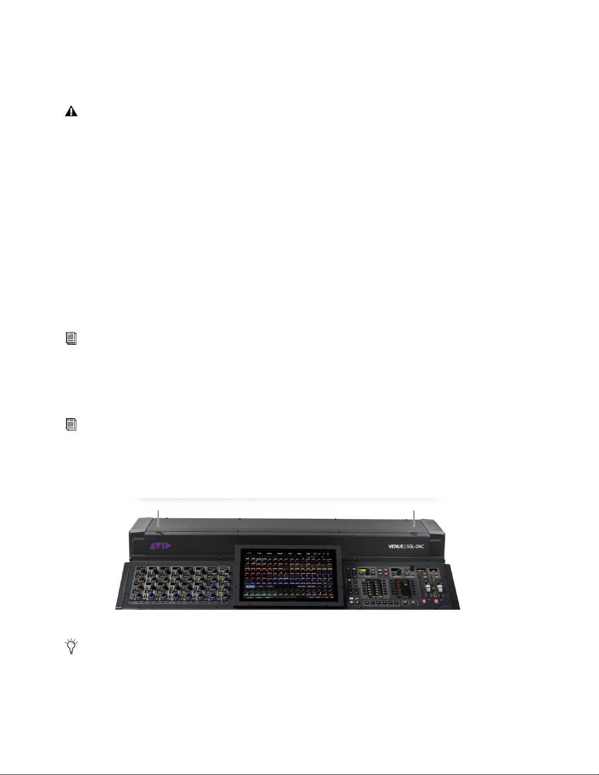
S6L Control Surface Overview 45
3 – PSUs
S6L-32D and 24D control surfaces provide dual-redundant hot-swappable PSUs with automatic failover. Each PSU provides an
On LED that lights green when the PSU is powered on and functioning properly. S6L-24C and S6L-16C provide dual redundant,
internal PSUs.
S6L Front Panel Features
USB 3.0 Port
Connect USB peripherals such as keyboards, bluetooth transmitters for wireless keyboards and mice, flash drives (for data trans-
fer), and iLoks (for plug-in authorizations) to this USB port.
Phones A (Left) and B (Right)
S6L-32D/24D/24C control surface provide two discrete headphone outputs, Phones A (left) and Phones B (right), each with its own
volume knob. S6L-16C provide a single headphone output. The Monitor buses feed the Phones outputs, and you can assign the
Monitor Bus (A or B) that feeds each Phones output on the
Options > Buses page of the external screen.
Phones volume is controlled using the corresponding Phone volume knob, though the level sent to each Headphone output is in part
determined by the overall level settings (such as Level Trim and Monitoring level) for the Monitor Bus that is feeding the particular
Phones output. Monitor Bus A and B controls are provided in the Monitoring section of the MLM, and on the Options > Buses
page of the external screen.
S6L Interior Secure USB Port
One USB 2.0 port is located within the S6L control surface to connect and securely protect an iLok Smart Key. Use this port to keep
one “master” iLok and its plug-in assets with the console at all times, safe from damage or loss.
S6L-24C/16C Console Lamp Ports
The S6L-24C and S6L-16C provide two ports on the top panel for connecting goose-neck console lamps. These ports are 3-pin
XLR and require LED lights. Brightness can be controlled from the Options > Interaction page of the external screen.
If the On LED does not light when the S6L is powered up, the PSU is faulty and may need to be replaced. For instructions on
removing and replacing PSUs, see
Replacing S6L and E6L PSUs
For more information on monitoring, see Soloing and the Monitor Buses.
The back cover of the S6L must be removed to access the secure USB port. For instructions see
S6L Secure USB Port.
Console lamp connectors on S6L-24C and S6L-16C (24C shown)
S6L-32D and 24D provide a built-in light bar instead of support for external console lamps. Light bar brightness can also be
adjusted from the Options > Interactions page.
Light Light

E6L Engine Overview 46
E6L Engine Overview
The E6L engine provides the real-time processing engine for input and output channels, and Pro Tools | HDX DSP processing
card(s) for AAX DSP plug-ins. The E6L engine also provides audio network, synchronization, and utility connections. All E6L en-
gine models provide the same connection capabilities.
E6L Cards and Features
You can install the following expansion cards in E6L engines.
HDX-192 DSP Expansion Cards
Each E6L engine provides a single HDX DSP card in its basic configuration. E6L-192 engines support up to four HDX DSP Ex-
pansion Cards, for increased plug-in processing. E6L-144 and E6L-112 engines support up to two HDX DSP Expansion Cards. For
installation instructions, see the HDX-192 DSP Installation.pdf.
AVB-192 Network Card
Each E6L includes one AVB-192 Network Card for connecting the E6L to other components in the system. You can add a second
AVB-192 card to expand the IO capability of the system, and to connect multiple systems to utilize I/O Sharing. For installation
instructions, see the AVB-192 Network Card.pdf.
MADI-192 MADI Option Card
The MADI-192 MADI Option Card is a high-channel-count MADI audio interface card for E6L engines. Each MADI-192 MADI
Option Card provides four MADI BNC connectors (2x coaxial in, and 2x coaxial out). Each pair of coaxial MADI inputs and out-
puts support up to 32 channels per I/O pair.
Up to four MADI Option cards can be installed in an E6L-192 or E6L-144 engine. Up to two MADI Option cards can be installed
in an E6L-112 engine. For installation instructions, see the MADI-192 MADI Card Installation guide.
WSG-HD Waves SoundGridOption Cards
The WSG-HD Waves SoundGrid Option Card from Avid lets you integrate Waves SoundGrid processing directly into your
VENUE | S6L mixes. Once the WSG-HD Card is installed in your E6L engine, plug-ins hosted on the Waves SoundGrid server ap-
pear on the VENUE Plug-Ins screen inside of the Waves SoundGrid Rack plug-in (up to 8 plug-ins per instance of SoundGrid
Rack). Up to two compatible Waves SoundGrid servers can be connected simultaneously for redundancy with automatic fail-over.
At the time of this writing, all E6L engines support a single WSG-HD card. In E6L-112 engines, either a single WSG-HD card or
a second MADI-192 MADI Option card can be installed. For installation instructions, see the
WSG-HD Card Installation guide.
While in use, the E6L engine must be oriented horizontally, with the bottom of the engine facing downwards.
Each MADI-192 MADI Option Card also has a single BNC Word Clock Output connector. At the time of this writing, the
Word Clock Output connector is not supported and should not be used.
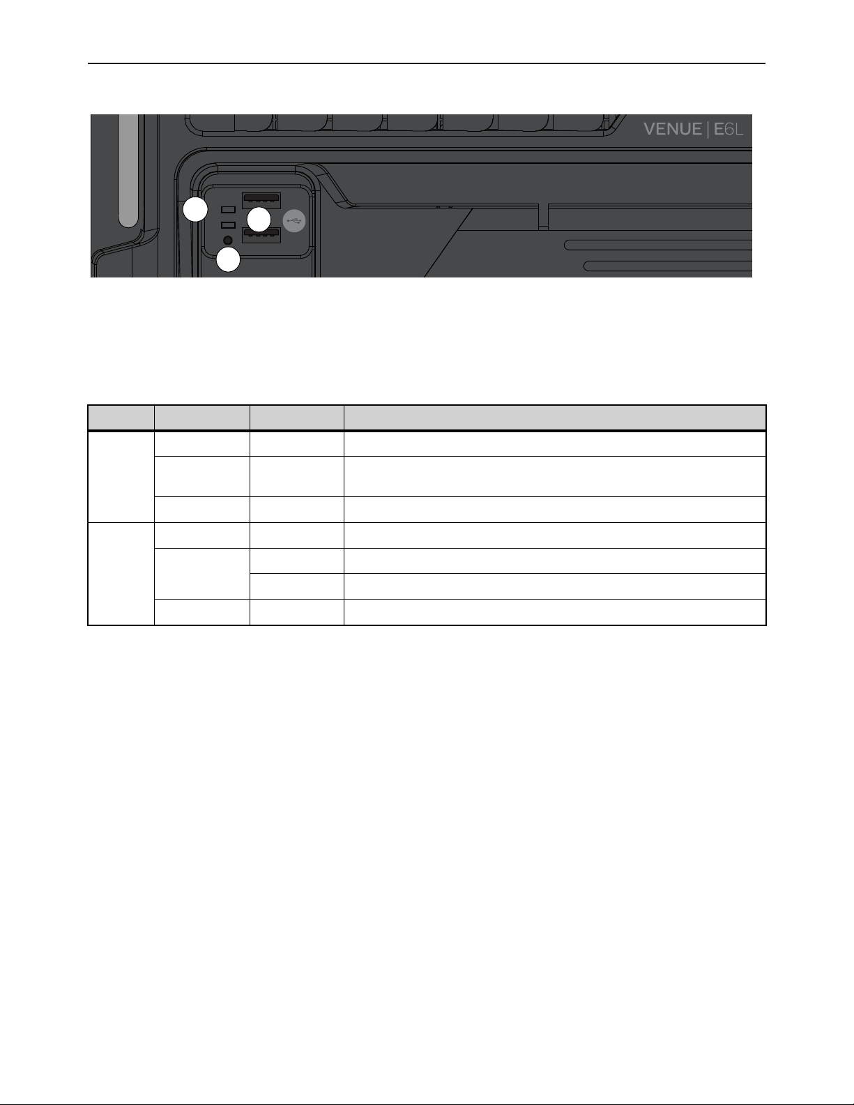
E6L Engine Overview 47
E6L Front Panel
The front panel of the E6L engine provides the following controls, connections and indicators:
1 – Status and System LEDs
These LEDs indicate the current status of the E6L engine, as described in the following table.
:
2 – Shutdown (Reset)
This button shuts down the software on the E6L engine. Only use this button to shut down the E6L if the engine has been discon-
nected from an S6L control surface and cannot be shut down via the Shut Down button on the Options > System page of the ex-
ternal VENUE software screen, or for troubleshooting purposes. See
E6L Engine Emergency Shutdown for more information.
3 – USB
Use these ports for installing system software and for troubleshooting and maintenance only. See
Using the System Restore
Software for more information.
E6L engine front panel
Status and System LEDs
LED Color State Description
Status
Green Solid All clear (no hardware alerts are detected).
Amber Solid
One or more hardware alerts are detected.
Consult the VENUE software Options > Devices page for detailed info.
Off (unlit) n/a E6L is powered off, or is initializing during startup.
System
Green Solid E6L is fully operational, and connected to the S6L control surface
Amber
Solid E6L processor has shut down; safe to power off E6L.
Flashing E6L processor is initializing.
Off (unlit) n/a E6L is powered off, or is initializing during startup.
STATUS
SYSTEM
SHUTDOWN
2
1
3
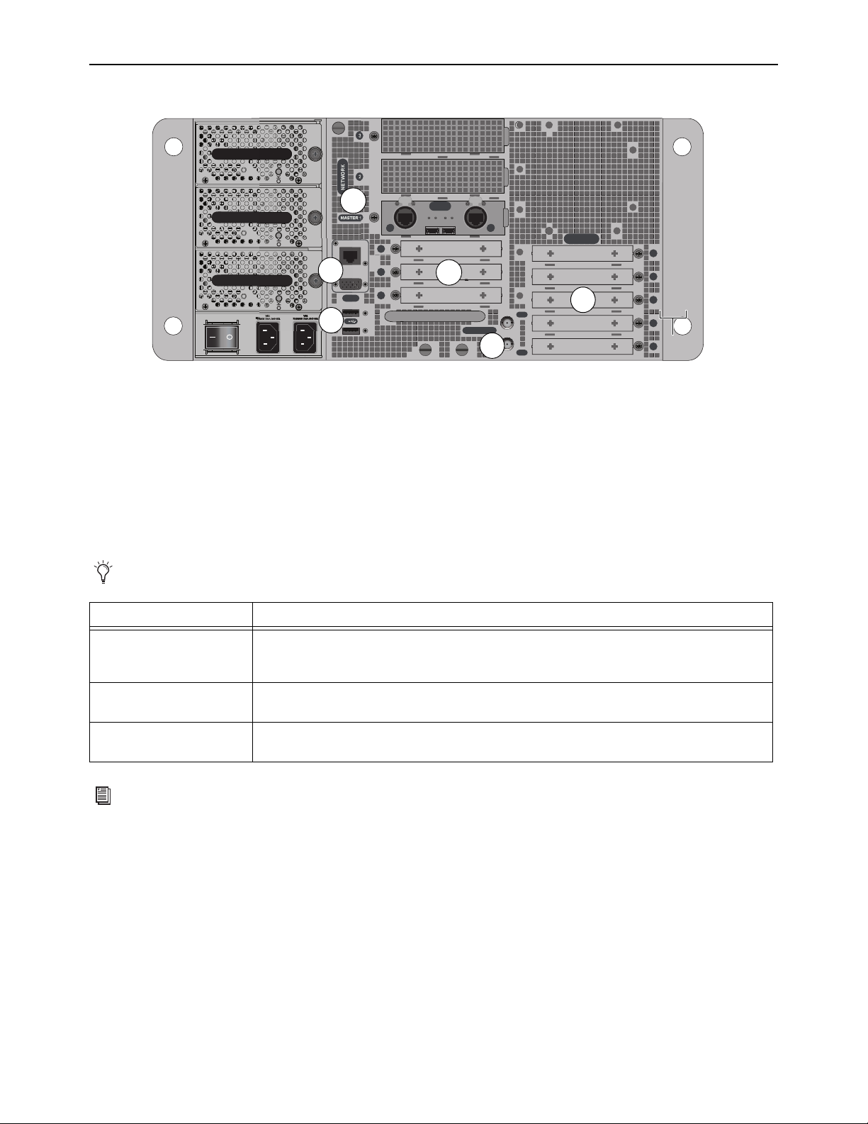
E6L Engine Overview 48
E6L Back Panel
E6L Engine Audio, Control, and Synchronization Connections
The E6L engine provides the following back-panel connections:
1 – Network (AVB-192 Network Card Slots)
These slots contain AVB-192 Network cards. Each AVB-192 card provides two AVB audio network connections (A and B) to con-
nect the control surface to other S6L system components. Each connection provides an RJ-45 with etherCON connector for copper
connections and an SFP transceiver module-compatible fiber-optic port for fiber-optic connections. Only one connection type
(copper or fiber-optic) can be active for each audio network connection.
2 – Expansion Card Slots
The back panel of the E6L engine provides eight half-length PCIe slots for Option cards such as the MADI-192 MADI Option
Card. Slots 1–5 are at the lower right and slots 6–8 are in the middle (below the AVB slots). At the time of this writing:
• Up to four MADI-192 MADI Option cards can be installed in slots 1–4 in an E6L-192 or E6L-144.
• A single WSG-HD card can be installed in any E6L. In E6L-192 and E6L-144, the WSG-HD card must be installed in Option
slot 6. In E6L-112 (only), the WSG-HD card must be installed in AVB Network slot 3.
For information on supported Option cards, visit
https://www.avid.com/products/venue-s6l-system.
E6L engine back panel (E6L-192/144 shown; E6L-112 back panel varies slightly as noted below)
Never connect both copper and fiber simultaneously to the same port (A or B).
AVB / Network Card Slots Description
Master 1
The AVB-192 Network card installed in this slot is the “master” AVB Network card in an S6L system.
When no other AVB-192 Network Cards are installed, its Network port B must be connected to the S6L
control surface. Port A on this card provides Ring 1 audio network connections to Stage I/O units.
2
This slot can contain a second AVB-192 Network card to expand Stage IO capacity, and to utilize I/O
sharing and gain tracking.
3
On E6L-112 engines (only) this slot can contain either a second MADI-192 MADI Option card, or a
WSG-HD Waves SoundGrid Option card. This slot is not supported in E6L-192 or E6L-144 engines.
For more information on audio network connections, see the VENUE S6L Installation Guide.pdf.
IN
OUT
WORD CLOCK
UTIL
EXPANSION
2
3
6
7
8
1
2
3
4
5
A
B
AVB-192
ACT SIG ACT SIG
ACT SIG ACT SIG
A
B
A
B
UTI
2
1
3
4
2
4
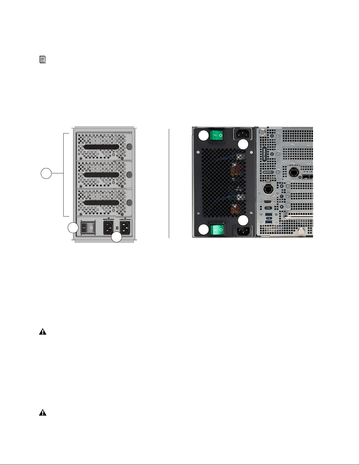
E6L Engine Overview 49
3 – Word Clock In and Out
(Two 75 Ohm Coaxial BNC Connectors)
These ports let you connect to the word clock ports of external digital devices to sync all digital devices in your system.
4 – Utility
(One RJ-45 Port, one VGA Display Port, and two USB 2.0 Ports)
Use these ports for installing system software and for troubleshooting and maintenance only. See
Using the System Restore
Software for more information.
E6L Engine Power Connections
E6L provides the following power connections, switches, and indicators:
1 – Power Switch(es)
These switches power E6L on and off, as follows:
On
Applies power to each PSU in the E6L-192 and E6L-144, and launches system software. On E6L-112, each PSU has its own
Power switch. S6L must be connected to a powered-up E6L engine for the system software to fully launch.
Off
Powers down the corresponding control surface PSU(s). VENUE software must be shut down properly from the Options >
System page of the external screen before turning the power switch to off (0). See Powering the System Up and Down.
2 – A and B AC Inlets
Connect either one of these inlets to an AC power source to provide power to all three PSUs. Connect each power inlet to a discrete
power source for AC source redundancy.
3 – PSUs
E6L-192 and E6L-144 engines provide three hot-swappable PSUs with automatic failover. Two PSUs are required to run the E6L
engine, and the third is a redundant PSU. Each PSU provides an On LED that lights green when the PSU is powered on and func-
tioning properly. E6L-112 provides dual redundant, internal PSUs.
See
Clock Synchronization Overview for more information.
E6L engine PSUs; E6L-192 and E6L-144 (shown at left) and E6L-112 (shown at right)
Do not power off the E6L engine until the Status LED is unlit and the System LED lights amber.
If the On LED does not light when the E6L is powered on, the PSU is faulty and may need to be replaced. For instructions on
removing and replacing PSUs, see
Replacing S6L and E6L PSUs.
OKOKOK
A
B
OK
K
OK
K
O
OK
K
O
1
2
3
1
1
2
2

Stage and Local I/O Rack Overview 50
Stage and Local I/O Rack Overview
Stage I/O units for S6L systems include Stage 64, Stage 32, and Stage 16.
Stage 64
Stage 64 is modular, and can be configured with a variety of I/O cards. Stage 64
supports up to eight input cards and four output cards, for a total of up to 64 in-
puts and up to 32 outputs (analog or digital).
Stage 64 also provides features such as the Stage 64 Menu with programmable
options and a corresponding display, MADI outputs, word clock output, as well
as a built-in confidence monitor with level control.
Stage 32
Stage 32 is also modular, and lets you connect up to 32 analog, digital, and/or
Dante inputs or outputs in a 5U rack. Integrating Stage 32 into S6L systems re-
quires dual AVB-192 Network Cards in the E6L Engine. Each Stage 32 sup-
ports up to a maximum 32 channels of inputs or outputs or a combination of
both. You can customize Stage 32 with any of the same analog I/O, digital I/O,
and Dante card options available for Stage 64, including SRI-192 Analog Input
cards, SRO-192 Analog Output cards, DSI-192 Digital Input cards, DSO-192
Digital Output cards, and DNT-192 Dante Option cards. Stage 32 also provides
MADI outputs.
Stage 16
Each Stage 16 provides 16 analog inputs, 8 analog outputs, and 4 digital out-
puts. Integrating Stage 16s into S6L systems requires dual AVB-192 Network
Cards in the E6L Engine.
Local 16
Local 16 lets you expand your local I/O capabilities, or add primary local I/O if
mixing on the S6L-16C control surface, by providing 8 XLR mic/line inputs, 8
XLR outputs, 4 pairs of XLR stereo AES/EBU inputs (8 channels total), and 4
pairs of XLR stereo AES/EBU outputs (8 channels total), similar to that on
S6L-32D/24D/24C control surfaces. Up to two Local 16 units can be connected
on the local (console) S6L AVB Network ring when using S6L-16C. A single
Local 16 can be used with other S6L systems. Integrating Local 16s into S6L
systems requires dual AVB-192 Network Cards in the E6L Engine.
For example configurations, requirements, and connection diagrams see the VENUE S6L Installation Guide.pdf.
Stage 64
Stage 32
Stage 16
Local 16

Stage and Local I/O Rack Overview 51
Stage 64 and Stage 32 I/O Card Features and Capabilities
You can install variety of analog and digital I/O cards in Stage 64 and Stage 32. You can purchase a pre-configured unit and modify
card configurations, or purchase an empty Stage 64 or Stage 32 and configure your rack as desired. For instructions on installing
I/O cards, see the
S6L Stage I/O Card Installation Guide (for Dante card installation, see the DNT-192 Network Card.pdf).
SRI-192 Analog Input Card
• Eight channels of analog mic/line inputs via XLR-3 female connectors
• +48V phantom power, 20 dB pad, and phase reverse (all selectable per channel via the control surface and VENUE software)
• Signal and phantom power LEDs for each channel
• 24-bit A/D conversion, up to 192 kHz sample rate
DSI-192 Digital Input Card
• Eight channels of digital inputs via four two-channel AES/EBU XLR3-female connectors or a single ADAT TOSLINK opti-
cal connector
• Automatic sample rate conversion (SRC) and detection on input; manually defeatable for lowest possible input latency
• SRC and Lock status LEDs for both AES and ADAT connections
• Word clock output for synchronizing external digital devices
SRO-192 Analog Output Card
• Eight channels of analog line outputs via male XLR-3 connectors
• Automatic muting for system protection
• Signal and Mute LEDs for each channel
• 24-bit D/A conversion
DSO-192 Digital Output Card
• Eight channels of digital outputs via four two-channel AES/EBU XLR3-male connectors and/or a single ADAT TOSLINK
optical connector
• Simultaneous output to both AES/EBU outputs and ADAT optical output
• Automatic muting for system protection
• Signal and Mute LEDs for each AES/EBU channel pair
DNT-192 Network Card
• Sixteen channels of digital input or output, or eight input and eight output channels (Stage 64 only), for connecting to Dante
network devices.
See Working with DSI-192 Digital Inputs for information on working with DSI ADAT and SRC functionality.
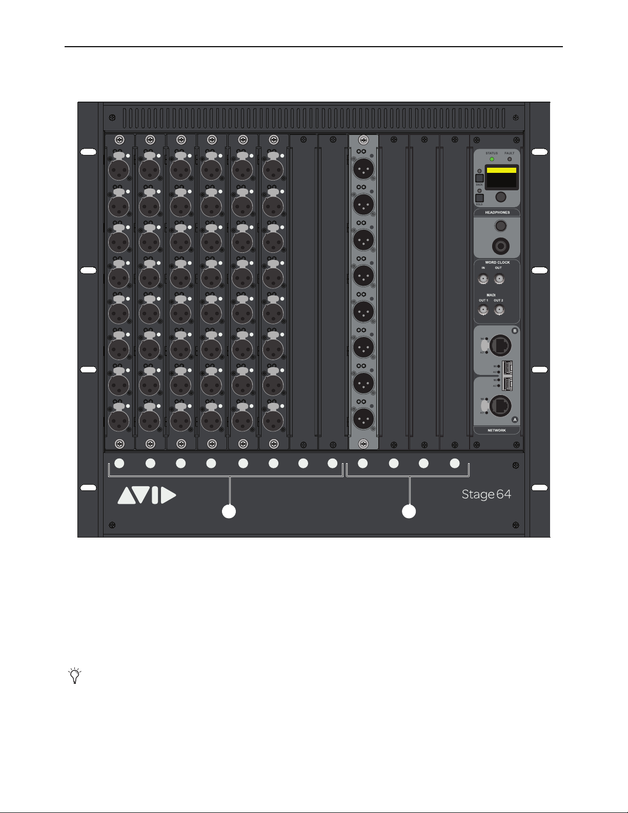
Stage and Local I/O Rack Overview 52
Stage 64 Front Panel
The front panel of the Stage 64 provides I/O card slots for I/O cards, and the Stage 64 Controller.
I/O Card Slots
1 – Slots A–H (Input Cards)
Install up to eight of any combination of SRI-192 and DSI-192 input cards, or up to four DNT-192 cards, in these slots.
2 – Slots J–M (Output Cards)
Install up to four of any combination of SRO-192 and DSO-192 output cards, or up to two DNT-192 cards in these slots.
Stage 64 front panel (48 x 8 configuration shown
A single DNT-192 card can also be installed in slots H and J, providing eight input and eight output channels. For more informa-
tion, see the DNT-192 Dante Option Card.pdf.
1
2
3
4
5 6
ABCD EFGHJKLM
1
2
3
4
5
6
7
8
SIG +48V
SIG +48V
SIG +48V
SIG +48V
SIG +48V
SIG +48V
SIG +48V
SIG +48V
INPUT
SRI-192
1
2
3
4
5
6
7
8
SIG +48V
SIG +48V
SIG +48V
SIG +48V
SIG +48V
SIG +48V
SIG +48V
SIG +48V
INPUT
SRI-192
1
2
3
4
5
6
7
8
SIG +48V
SIG +48V
SIG +48V
SIG +48V
SIG +48V
SIG +48V
SIG +48V
SIG +48V
INPUT
SRI-192
1
2
3
4
5
6
7
8
SIG +48V
SIG +48V
SIG +48V
SIG +48V
SIG +48V
SIG +48V
SIG +48V
SIG +48V
INPUT
SRI-192
1
2
3
4
5
6
7
8
SIG +48V
SIG +48V
SIG +48V
SIG +48V
SIG +48V
SIG +48V
SIG +48V
SIG +48V
INPUT
SRI-192
1
2
3
4
5
6
7
8
SIG +48V
SIG +48V
SIG +48V
SIG +48V
SIG +48V
SIG +48V
SIG +48V
SIG +48V
INPUT
SRI-192
SIG MUTE
MUTE
MUTE
MUTE
MUTE
MUTE
MUTE
MUTE
SIG
SIG
SIG
SIG
SIG
SIG
SIG
OUTPUT
SRO-192
1
2
3
4
5
6
7
8
Home >
<empty-name> 96k
Net OK Mon On
HW OK MADI On
1 2
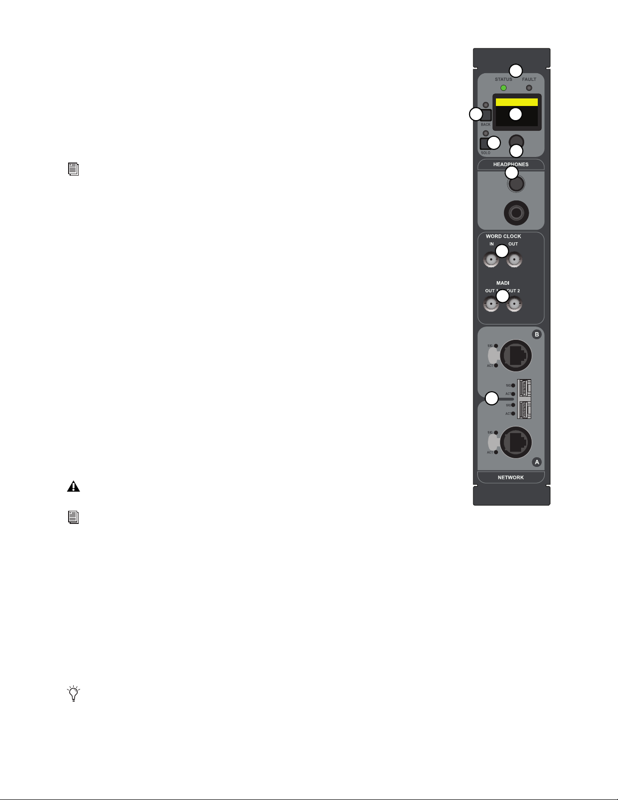
Stage and Local I/O Rack Overview 53
Stage 64 Controller
All Stage 64 I/O racks include a Controller. The Controller provides the following features:
1 – Status and Fault LEDs
These LEDs provide the following indications:
STATUS
Indicates the current status of the audio network connection to the Stage 64 Network ports.
FAULT
Indicates the current status of the Stage 64 hardware, such as fan and internal temperature.
2 – Stage 64 Controller Display
This display shows the current settings of the Stage 64 (via the HOME page), and provides access to var-
ious pages of Stage 64 parameters. For more information see Stage 64 Controller Display.
3 – Display Selector
This knob lets you navigate through the pages and change the configurable settings provided in the display.
4 – Back
This button lets you back out of the pages and sub-pages provided in the display.
5 – Solo
This switch sends the channel selected in the Controller Menu to the Stage 64 Headphones output.
6 – Headphones
This section provides a 1/4-inch stereo jack and a level control to monitor Stage 64 input and output chan-
nel signals. For more information see
Using the Stage 64 Confidence Monitor.
7 – Word Clock In and Out
(Two 75 Ohm Coaxial BNC Connectors)
The Word Clock Out port provides S6L system word clock output to sync external digital devices to the
S6L system.
8 – MADI Out 1 and 2
(Two 75 Ohm Coaxial BNC Connectors)
MADI Outs 1–2 provide fixed one-for-one digital splits of up to 64 inputs from the Stage 64. For more information, see
Using
MADI Outs on Stage 64 and Stage 32.
9 – Network A and B
(Two RJ-45 Ports with etherCON Connectors and two SFP module-compatible fiber-optic ports)
Stage 64 provides two connections (A and B) to connect Stage 64 to other S6L system components. Each connection provides an
RJ-45 with etherCON connector for copper connections, and an SFP module-compatible fiber-optic port for fiber-optic connec-
tions.
See
S6L System Components LED Codes for more information on LED codes.
The Word Clock In port is not functional.
S6L system digital inputs also provide sample rate conversion (SRC) for synchronizing digital inputs.
See
Synchronizing AES/ADAT Digital Audio Inputs (SRC) for more information.
Only one type of connection (copper or fiber-optic) can be active at a time for each port. Never connect both copper and fiber
to the same port (A or B).
Home >
<empty-name> 96k
Net OK Mon On
HW OK MADI On
1
2
6
7
8
9
3
4
5

Stage and Local I/O Rack Overview 54
Making Stage I/O Unit Connections
Connecting and Assigning Stage I/O Units
Physically connect Stage I/O units to the AVB-192 cards in the E6L engine, and connect input sources and output destinations to
the I/O installed in your Stage I/O units. Once connected and powered on, assign Stage I/O units in the Options > Devices page
of the external VENUE software screen to available Stage slots. See the VENUE S6L Installation Guide.pdf for more information.
Patching Stage I/O
Once you have assigned Stage I/O units to Stage slots, you can then patch Stage I/O to VENUE system channels under the Stage
1–6 tabs in the VENUE Patchbay.
• To patch Stage inputs to VENUE system channels, see Patching Input Sources to Input Channels.
• To patch outputs, see Patching Output Channels to Hardware Outputs.
Stage 64 Controller Display
The Stage 64 Controller display provides pages and menus from which you can view and adjust Stage 64 parameters. The HOME
page provides an overview of the current status of various Stage 64 parameters. The main MENU provides access to the MONITOR,
SETTINGS, MUTE, and STATUS menus, from which you can access various Stage 64 parameters, including the built-in confi-
dence monitor for monitoring individual Stage 64 inputs and outputs.
Stage 64 Controller Display HOME Page
The HOME page provides an overview of the current status of the Stage 64, as follows:
Name
Shows the name given to the Stage 64. You can name the Stage 64 from the Options > Devices page of the external VENUE
software screen, or from the Controller Menu Settings page.
Net OK/ERR
Shows the current status of the audio network connection to the Stage 64 Network ports. OK mirrors a lit-green STA-
TUS LED, and ERR mirrors a lit-red STATUS LED.
HW OK/ERR
Shows the current status of the Stage 64 hardware. OK mirrors a lit-green STATUS LED, and ERR mirrors a lit-red
STATUS LED.
Sample Rate
Shows the current S6L system sample rate.
Mon On/Off
Shows the current on/off status of the built-in Confidence Monitor.
MADI On/Off
Shows the current on/off status of the Stage 64 MADI Outs.
Controller Menu HOME page
HOME
<Stage 64> 96k
Net OK Mon On
HW OK MADI On
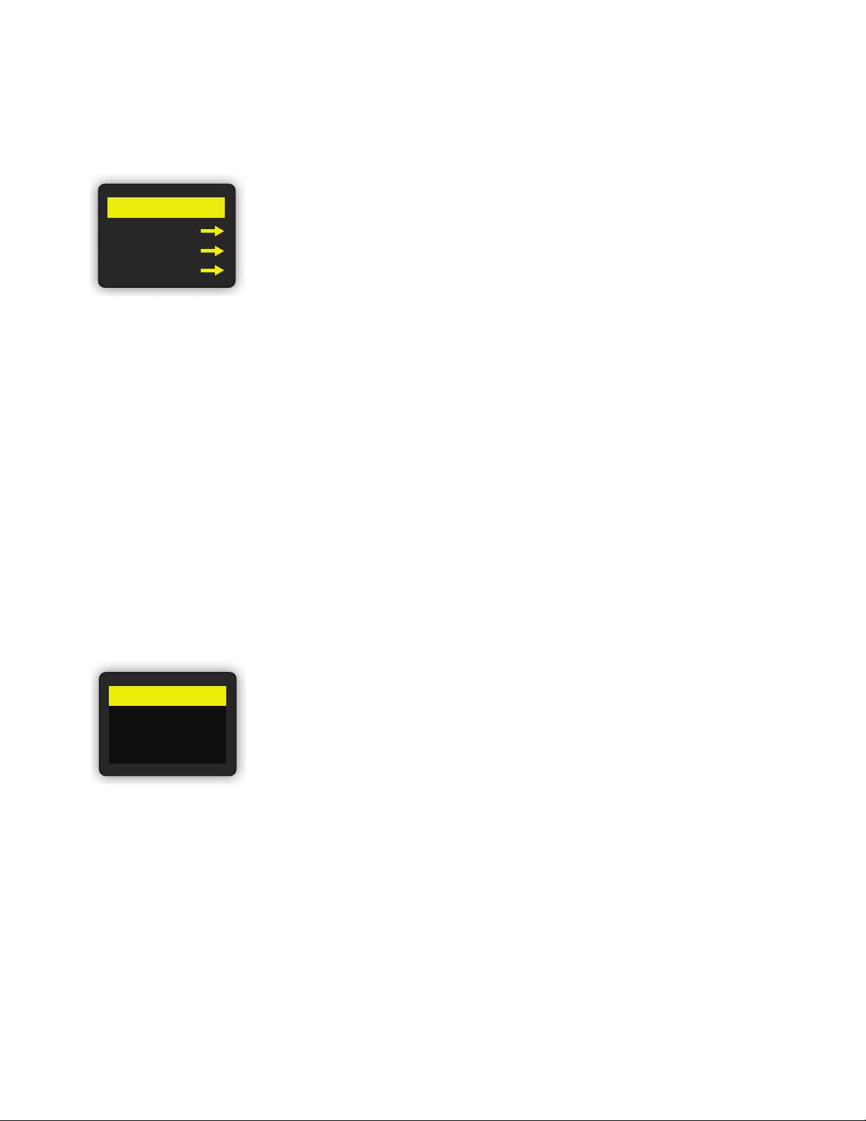
Stage and Local I/O Rack Overview 55
Controller Main MENU
The main MENU lets you access the MONITOR, SETTINGS, and MUTE menus (via page 1), and the STATUS menu (via page 2).
To access the MENU page 1 (MENU 1/2):
From the HOME page, press the Display Selector.
Controller MONITOR Menu
The MONITOR menu lets you target a Stage 64 input or output channel for monitoring using the Headphones output on the Stage
64. See Using MADI Outs on Stage 64 and Stage 32 for more information.
Using the Stage 64 Confidence Monitor
You can monitor signals from individual Stage 64 inputs and outputs using the Stage 64 Headphones output. Use this to trouble-
shoot individual inputs and outputs connected to the Stage 64.
To use the Stage 64 Confidence Monitor:
1 Connect a pair of headphones to the Headphones output on Stage 64.
2 From the HOME page, press the Display Selector.
3 Select MENU 1/2 so it is highlighted, and press the Display Selector.
4 Rotate the encoder so MONITOR is highlighted, then press the Display Selector. The first input of the input card installed in slot
A is shown in the display (A1-01), where A1 denotes card slot A connector 1, and 01 denotes the VENUE system channel that
hardware input or output is assigned to. If the channel is assigned in the VENUE Patchbay, the name of the channel appears un-
derneath.
.
5 Rotate the Display Selector to scroll through the I/O card slots until you locate the desired channel.
6 Press SOLO so it lights, then adjust the volume using the Headphone level control, located above the Headphones output.
7 To disable the Headphone output, press SOLO so it is unlit.
Main MENU page 1
Monitor screen showing the first input of the input card in slot A
MENU 1/2
MONITOR
SETTINGS
MUTE
MONITOR
Kick
A1-01

Stage and Local I/O Rack Overview 56
Controller SETTINGS Menu
The SETTINGS menu provides two pages (SETTINGS 1/2 and SETTINGS 2/2) of configurable Stage 64 parameters, including
MADI Out and confidence monitor settings. You can also name and reset the Stage 64.
To access the SETTINGS menu:
1 From the HOME page, press the Display Selector.
2 Select MENU 1/2 so it is highlighted, and press the Display Selector.
3 Rotate the encoder so SETTINGS is highlighted, then press the Display Selector. The first SETTINGS page is shown
(SETTINGS 1/2).
The Settings menu provides the following parameters:
Naming the Stage 64
To name the Stage 64 from the Stage 64:
1 With SETTINGS 1/2 highlighted, press the Display Selector to access the second SETTINGS page (SETTINGS 2/2).
2 Rotate the Display Selector so DEVICE is highlighted, then press the Display Selector.
3 Rotate the Display Selector so the field under NAME is highlighted, then press the Display Selector. The cursor under the first
character appears.
4 Do any of the following to enter characters (up to a 32 character maximum)
• Rotate Display Selector to cycle through the available characters.
• Press the Display Selector to enter the selected character and move the cursor to the next position.
• Press and hold the Display Selector to move the cursor to the previous position.
5 When you have finished entering a name, press BACK once.
6 Do either of the following:
• To apply the new name, scroll the Display Selector to highlight APPLY, then press the Display Selector.
• To cancel, scroll to highlight CANCEL then press the Display Selector.
SETTINGS menu parameters
SETTINGS Menu
Page
SETTINGS
Menu Options
Parameters Description
Page 1 (1/2)
NETWORK
n/a (only adjust when instructed to do so
by Avid customer support)
View Stage 64 DHCP setting, and MAC
and IP addresses
MADI Out SPLIT ON/OFF Toggle Stage 64 MADI Outs on/off
SRC 48 kHz or 96 kHz Set the MADI Outs sample rate
MONITOR MONITOR ON/OFF
Toggle confidence monitor on/off (default
is ON)
Page 2 (2/2) DEVICE
NAME Change the name of the Stage 64
RESET Resets the Stage 64 to default settings
Changing any NETWORK settings on the SETTINGS menu may render your Stage 64 incapable of connecting to other S6L system
components. Only adjust these settings when troubleshooting with Avid customer support.
You can also name the Stage 64 on the Options > Devices page of the external VENUE software screen. See
Devices for more
information.

Stage and Local I/O Rack Overview 57
Resetting Stage 64
To reset the Stage 64 from the Stage 64:
1 With SETTINGS 1/2 highlighted, press the Display Selector to access the second SETTINGS page (SETTINGS 2/2).
2 Rotate the Display Selector so DEVICE is highlighted, then press the Display Selector.
3 Rotate the Display Selector so RESET is highlighted, then press the Display Selector.
Controller MUTE Menu
The MUTE menu lets you mute all the outputs on Stage 64.
When a Stage 64 is used in an I/O sharing configuration, note that muting from the Controller MUTE menu mutes all outputs on
that Stage 64.
To mute/unmute Stage 64 outputs from the Stage 64.
1 From the HOME page, press the Display Selector.
2 Rotate the Display Selector so MUTE is highlighted.
3 Press the press the Display Selector. The MUTE menu is shown.
4 Rotate the Display Selector so MUTE ALL is highlighted. Press the Display Selector to toggle MUTE ALL on/off. The Mute
LEDs on all output connectors in the Stage 64 light when they are muted.
Controller STATUS Menu
The STATUS menu is accessed from the second page of the main MENU.
To access the STATUS menu:
1 From the HOME page, press the Display Selector. MENU 1/2, MONITOR, SETTINGS, and MUTE are shown in the display.
2 With MENU 1/2 highlighted, press the press the Display Selector to access the second MENU page (MENU 2/2).
Main MENU page 2
MENU 2/2
STATUS

Stage and Local I/O Rack Overview 58
3 Rotate the Display Selector so that STATUS is highlighted, then press the knob. The STATUS menu is shown, and provides
pages of options detailing the current status of the Stage 64, as follows:
STATUS menu parameters
STATUS Menu
Pages
Parameter Status Description
NETWORK
STATUS
CONN
Valid communication exists between this Stage 64 and other
S6L devices on the network
ERR
No communication exists between this Stage 64 and other
S6L devices on the network
LINK SPEED
10 Current network speed is 10mbit/second
100 Current network speed is 100mbit/second
1000 Current network speed is 1000mbit/second
PORT
COPPER RJ45 Network port is the active audio network port
OPTICAL The fiber-optic Network port is the active audio network port
HW MONITOR
FAN SPEED <n> RPM Internal fan speed in revolutions per minute
TEMP 1 <n> c PSU 1 temperature in Celsius
TEMP 2 <n> c PSU 2 temperature Celsius
FIRMWARE
Board 1 Firmware Version Current firmware version for AVB Network card
Board 2 Firmware Version Current firmware version for AVB Network card

Stage and Local I/O Rack Overview 59
Using MADI Outs on Stage 64 and Stage 32
The two MADI Out connectors on the Stage 64, and the single MADI Out on Stage 32, provide fixed one-for-one digital splits of
input channels from the corresponding unit (up to 64 input channels from Stage 64, and up to 32 from Stage 32) at a 48 or 96 kHz
sample rate. These let you connect an external MADI device such as a Pro Tools | HD MADI without needing to configure the
VENUE software Patchbay. You can enable and disable the MADI Outs on a per Stage unit basis.
Channel assignments for each Stage 64 MADI Out are as follows:
The single MADI Out port on Stage 32 carries up to 32 input channels (depending on Stage 32 I/O configuration) regardless of sam-
ple rate.
Configuring Stage 64 and Stage 32 MADI Outs
You can set the sample rate of Stage 64 and Stage 32 MADI outs from the external screen. You can toggle the MADI Outs on/off
and set the sample rate from the Stage 64 Controller.
Setting the MADI Outs sample rate from the external screen:
1 Put the system into Config mode by pressing the Config switch on the control surface MLM so it is lit (see
Enabling Config
Mode for more information).
2 On the external screen, go to the Options > Devices page.
3 In the Available Devices or Connected Devices column, select the Stage 64 or Stage 32 whose MADI sample rate you want to
adjust so it is highlighted in blue.
4 In the Information section, select the Settings tab.
5 Under MADI, select the Sample Rate pop-up menu and choose the desired sample rate.
Configuring Additional Stage 64 MADI Out Settings
To configure Stage 64 MADI Outs from the Stage 64 Controller:
1 Press and hold Back to make sure the Stage 64 Controller Home page is shown in the display.
2 Press the Display Selector once, so page 1 of the Menu is shown in the display.
3 Rotate the Display Selector to the right so Settings is highlighted, then press the Menu Selector so the Settings menu is shown.
4 Rotate the Menu Selector to the right so MADI SPLIT is highlighted, then press the Menu Selector so the MADI Split menu is
shown.
5 To toggle the MADI Outs on/off, do the following:
• Rotate the Display Selector to the right so SPLIT is highlighted.
• Press the Display Selector so ON or OFF appears next to SPLIT.
6 To set the sample rate of the MADI outs:
• Rotate the Display Selector to the right so SRC is highlighted.
• Press the Display Selector so the desired sample rate appears in the display (48 kHz or 96 kHz).
Sample Rate MADI Out Channel Assignments
48 kHz
Out 1
Stage 64 inputs 1–64
Out 2
Stage 64 inputs 1–64
96 kHz
Out 1
Stage 64 inputs 1–32
Out 2
Stage 64 inputs 33–64
The pickoff point for MADI Outs splits is post-pad, post-analog gain, and pre-digital gain.

Part II: Using S6L

Configuring System Audio 61
Configuring System Audio
The chapter describes how to do the following basic system configuration tasks:
•
Powering the System Up and Down
• Confirming System Components
• Pairing the E6L and S6L
• Enabling Config Mode
• Assigning Stage I/O Units
• Assigning Local 16
• Setting the System Clock
• Configuring Mains and Mix Buses
• Managing Connections
For complete hardware and software installation instructions. the VENUE S6L Installation.pdf.

Configuring System Audio 62
Powering the System Up and Down
Use the following instructions to power the system up and down for regular, day-to-day start up and shut down after the system(s)
have been connected and configured as explained in the VENUE |S6L Installation Guide.
Make sure you have installed the most recent VENUE software.
Power up the system in the following sequence:
1 If more than one system is connected for I/O Sharing, do the following steps for the Clock Master system first.
2 If applicable, power on routers for use with ECx remote control.
3 Power on any connected computers for recording/playback.
4 Power on the connected video monitor.
5 Power on the E6L engine by pressing the power switch(es) on the back to the on (1) position. On the front panel of the E6L en-
gine, the front-panel LEDs light as follows:
• Status LED lights green.
• The System LED begins to flash amber while the E6L is waiting to connect to the S6L control surface, then turns green when
connection is complete.
6 Power on the S6L control surface by pressing the power switch on the back panel
to the on (1) position.
The LEDs on each of the S6L’s PSUs light green, and Avid logos appear on the
Master Touch Screen (MTS), the Channel touch Modules (CTMs) (if present),
and the external screen while the system initializes.
If you are powering up the system for the first time, or the S6L control surface is
connected to a different E6L engine than it was previously connected to, the
Please Select Engine screen appears on the MTS when initialization is complete.
.
If the Please Select Engine dialog appears, complete the rest of these power up instructions and then proceed to
Confirming Sys-
tem Components.
If you have not installed the most recent VENUE software, or if on initial power-up S6L prompts you to update your system,
go to the Avid account linked to your S6L purchase to download the latest software and plug-in installers. Instructions for in-
stalling VENUE software are provided in the VENUE | S6L Installation Guide, available as a PDF in your Avid account.
Make sure no VGA monitor, mouse, keyboard, or internet is connected to the E6L engine before powering up your S6L system.
Please Select Engine Screen on the MTS
If the E6L engine has not fully initialized by the time the S6L control surface has initialized, “Waiting for the E6L Engine to
start...” appears in the MTS until the E6L finishes initializing.
Avid logo on-screen

Configuring System Audio 63
7 Power on the first Stage I/O unit by pressing the power switch to the On position for the PSU that is plugged into an AC power
source. Stage 64: If both PSUs are connected for redundancy, power-on both PSUs. The power switch(es) lights green and the
following occurs on the front panel of the Stage 64:
• The
Status LED lights green.
• The AVID logo appears while the device initializes.
• When initialization is complete, the Controller Menu
HOME page is shown.
8 Power on any other Stage I/O units in the system.
9 Proceed to
Confirming System Components.
Powering Down the System
Power down the system in the following sequence:
1 Turn off the audio monitoring system.
2 Turn off any connected computers for recording/playback.
3 Shut down your system by doing the following:
• Put the system into Config mode (see Enabling Config Mode).
• On the external VENUE software screen, go to the Options page and select the System tab.
•Select Shut Down.
•Select Shut Down again to confirm.
4 When the MTS and the external screen go black, power off the S6L control surface using the back-panel power switch.
5 On the front panel of the E6L engine, once the Status LED is unlit and the System LED is lit amber you can power off the E6L
using the back-panel power switch.
6 Power off any connected Stage I/O units.
Controller Menu HOME page
You can also access system Shut Down on the MTS by tapping the Gear icon in the lower right corner.
HOME
<Stage 64> 96k
Net OK Mon On
HW OK MADI On

Configuring System Audio 64
Confirming System Components
After connecting and powering up system components, you can confirm and configure system components on the
Options > Devices page of the VENUE software screen.
To confirm system components:
1 On the external screen, select the Options button.
2 Select the Devices tab.
All connected and powered on system components appear on the Devices page. The Devices page lets you connect and trouble-
shoot system components, view their status, and edit hardware settings.
• If any components do not appear, check all network connections between components, and make sure all components are
powered on.
• It is possible for some components to appear mis-identified (for example, an S6L-24C control surface might be mis-identifed
as an S6L-24D). If this occurs, right-click on the image of the mis-identified component and select the correct one from the
pop-up menu.
• If components still not appear, or error messages are displayed, see
Troubleshooting.
3 Proceed to Pairing the E6L and S6L.
Options button
Devices tab
Options > Devices tab
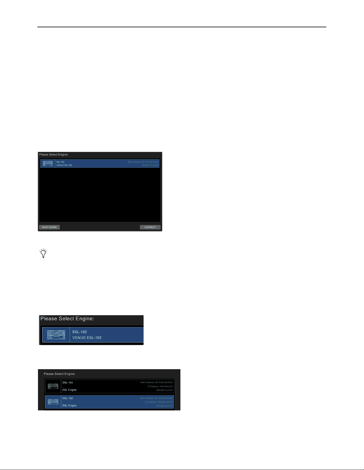
Configuring System Audio 65
Pairing the E6L and S6L
By default, an E6L engine automatically connects to its previously assigned S6L control surface. When assigned to an E6L, the S6L
controls the parameters associated with that E6L. After the initial assignment, an E6L will automatically attempt to reconnect to the
most recently assigned S6L. However, you can assign any E6L to any S6L on the network.
• If you are configuring a system for the first time, have just performed a System Restore, or the S6L control surface is connected
to a different E6L engine than it was previously connected to, the
Please Select Engine screen appears on the MTS (or external
screen with S6L-16C) when initialization is complete. If so, follow the instructions in
Please Select Engine.
• If your S6L control surface was already paired with an E6L engine, and that E6L engine is detected on the network, the system
will startup as usual and automatically connect. If so, proceed to
Assigning Stage I/O Units. If your configuration has not
changed and components were already paired prior to performing a Software Update, you should not need to pair them again; if
this is the case, proceed to Setting the System Clock.
• If you ever need to re-assign components, see
Managing Connections.
Please Select Engine
.
To pair your E6L engine to your S6L control surface, in the Engine Selection screen on the MTS do the following:
1 If you have not already done so, power on the E6L engine by pressing the power switch on the back to the on (1) position.
On the front panel of the E6L engine, the front-panel Status LED lights green and the System LED flashes amber while the E6L
engine initializes.
On the MTS, the Please Select Engine screen appears.
If multiple E6L engines are detected, all are listed.
2 In the Please Select Engine screen, select a connected E6L engine so it is highlighted in blue.
Please Select Engine Screen on the MTS (or on the external screen for S6L-16C)
If the E6L engine has not fully initialized by the time the S6L control surface has initialized, “Waiting for the E6L Engine to
start...” appears in the MTS until the E6L finishes initializing.
A selected E6L engine.
Selecting an E6L from the list of available engines (E6L-192 shown selected)
Configuring System Audio 66
3 Select CONNECT.
The MTS (or external screen with S6L-16C) indicates that the S6L control surface is waiting for the E6L engine to start. When
the devices connect, the Universe view appears on the MTS, and the Inputs page appears on the external screen.
Firmware and software updates begin on various devices in the system, as follows:
• Surface modules (the Channel Fader Modules and the Channel Knob Modules), and status is indicated on the MTS.
• S6L control surface and E6L engine Network cards, and status is indicated on the Options > Devices page of the external
screen.
• Any Channel Touch Modules (CTMs), and status is indicated on the CTMs.
4 On the external VENUE software screen, in the Console Network Card alert dialog, click Review to monitor the progress of
firmware updates.
5 If desired, give each S6L and/or E6L a unique name by doing the following:
• Enable Config mode.
•In the Options > Devices tab of the external screen, select the E6L engine or S6L control surface graphic so it is outlined in
blue.
• In the Information pane, select the
DEVICE tab.
• Touch-and-hold (double-click) the field next to Name, enter a unique name using the keyboard, then press Enter when fin-
ished.
6 Proceed to
Enabling Config Mode.
Connect button
If you have incorrectly assigned E6Ls, they must first be unassigned from the S6Ls to which they are currently assigned. See
Managing Connections.
On some systems the CTMs (if any) might indicate that you must power-cycle your system to complete software installation.
Do not power-cycle your system at this time. Wait until the instructions in this guide tell you to power-cycle the system.
During the E6L engine update, alerts are shown indicating that connection between the S6L control surface and the E6L en-
gine has been lost, and plug-in racks need reset. These alerts can be ignored, as they are a normal part of the update process.
Device names are not saved as part of Show files, they are stored in the hardware unit. In addition, you cannot rename devices
in the Standalone software.
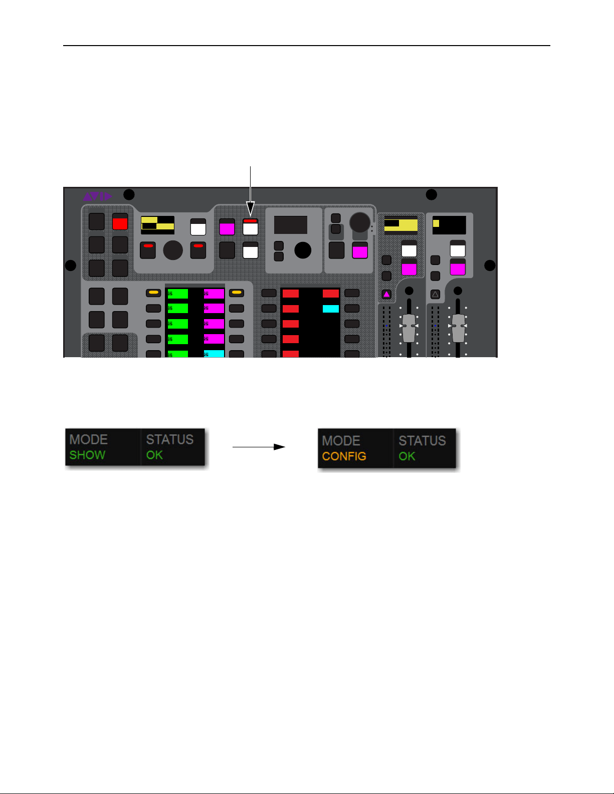
Configuring System Audio 67
Enabling Config Mode
There are two main operating modes for the S6L system, Config mode and Show mode. Use Config mode to accomplish tasks such
as setting up your system, configuring options, loading Show files, and installing software such as plug-ins and system updates. Use
Show mode to mix your performance.
To enable Config mode, do one of the following:
1 Press Config on the S6L control surface Master Live Module (MLM). The Config switch lights, and Config is indicated in the
Mode box in the on-screen Status Bar.
– or –
• On-screen, double-tap the
Mode box in the Status Bar, located in lower-right hand corner of the screen, so that Config is shown.
The Config switch also lights.
2 Proceed to
Assigning Stage I/O Units.
Config switch on the S6L control surface MLM
Mode box showing Show mode enabled (left) and Config mode enabled (right)
VENUE | S6L
Solo Solo
Home
Config
VCAs
Outputs
Layouts
Inputs
Recall
Store
Y
X
Y
X
AFL
Dim
In
Sel
SNAPSHOTS
Talk
Back
Multi
Select
Multi
Assgn
Default Fine
OK Cancel
Over
Write
Mix to
Mon
Solo
Clear
20
10
5
0
6
12
20
10
5
0
6
12
8All
Preview
ASSIGNABLE ENCODER MONITORING
Push A/BHold SIP
SHIFT
ALT
CTRL
ESC
Mute Mute
A
B
Nom
9
3
0
3
9
15
9
3
0
3
9
15
Inputs/Outputs Global Controls
0.0 dB
L
Left
0.0 dB
Kick
Mute Group 1
Mute Group
Function KeysMute Group 2
Mute Group 3
Mute Group 4
M1
M2
M3
M4
M5
001/011
reset all inputs
0.0 dB
CH 1
Kick
Ch 1-16
1-16
Aux 1-8
1-8
Aux 9-16
Aux 17-24
Aux 25-32
25-32
1-8
Ch 17-32
17-32 9-16
Ch 33-48
33-48 17-24
Ch 49-64
49-64
65-80
S1Cu2
001 3
P:S1C1
N:S1C3
S1Cu3
S1Cu2
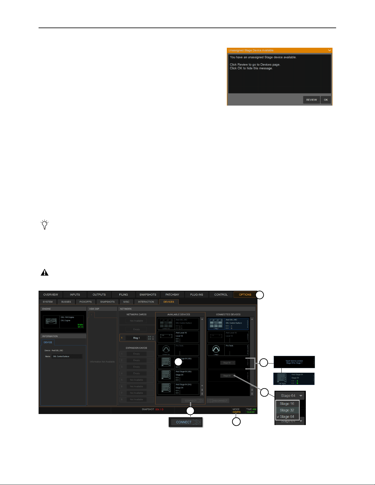
Configuring System Audio 68
Assigning Stage I/O Units
When you initially configure a system, or after performing a System Restore,
you must assign Stage 64, Stage 32, and/or Stage 16 I/O units to available
Stage slots in the Options > Devices tab. Each Stage slot corresponds to a
Stage hardware tab 1–6 in the VENUE Patchbay. A banner alert is displayed
whenever the system detects one or more I/O units that are unassigned.
• If your configuration includes one or more Local 16s you must also assign
them in Options > Devices. Unlike Stage I/O, however, Local 16 is as-
signed to S6L AVB network Ring 2. Assign Stage I/O first, as explained in
the following steps, before assigning Local 16.
• If you are configuring a basic (single) system, complete the following
steps to assign Stage 64s, Stage 32s, and/or Stage 16s to E6Ls.
• If you are configuring a system connected for I/O Sharing with another S6L system, complete the following steps to assign
Stage I/O units to E6Ls and then see Using Master and Slave E6Ls in Shared I/O Configurations.
To assign Stage I/O units (refer to Figure 1):
1 Make sure the system is in Config Mode (see
Enabling Config Mode).
2 Navigate the external screen to Options > Devices.
3 If your configuration includes Stage 32 or Stage 16, configure Stage slots in the CONNECTED column by clicking to select the
slot and then choosing the appropriate device from the selector.
4 In the AVAILABLE column, select the first Stage I/O device so it is highlighted (to identify units when multiple devices are pres-
ent, see Identifying Stage I/O Units).
5 Click CONNECT.
6 Click to select a flashing Stage slot and assign the selected I/O unit to that slot.
7 Repeat for any additional Stage I/O units.
If any connected Stage I/O units do not appear in the Unassigned section, check network and power connections.
On initial power-on after performing a System Restore, firmware updates of the Stage units begin just after assigning them.
Figure 1. Assigning Stage I/O units in Options > Devices
Unassigned Stage I/O alert
2
4
3
6
5
11

Configuring System Audio 69
When using more than one type of Stage IO unit, group units by type and connect them in series in the CONNECTED DEVICES
column, such as all Stage 64(s), then all Stage 32s, then all Stage 16s. The order of Stage I/O devices in the Connected Devices col-
umn does not need to match the order of physical network connections.
Virtual Soundcheck: Important Note
Slot designation (1–6) determines where I/O appears in the Patchbay I/O tabs 1–6, which
also determines Virtual Soundcheck channel order. For example, each Stage 16 slot occupies 16 channels of Virtual Soundcheck.
However, switching any slot from Stage 64 to Stage 16 creates four available Stage 16 slots. Even if only one Stage 16 I/O unit is
physically connected and the remaining three Stage 16 slots are empty, if a Stage 64 was assigned and connected to slot 5 the
Pro Tools inputs corresponding to that Stage 64 will begin at channel 65. To avoid this, it is recommended to assign Stage 64s (if
any) to the lowest numbered slots
1–3 whenever possible, followed by any Stage 32s, followed by any Stage 16s.
8 Once firmware updates are complete, dismiss all alerts and dialogs by selecting OK in each one.
9 If desired, give each Stage I/O unit a unique name by doing the following:
• Make sure the system is in Config mode (see
Enabling Config ModeEnabling Config Mode).
• In the Options > Devices tab of the external screen, select the appropriate Stage I/O graphic so it is outlined in blue.
• In the Information pane, select the DEVICE tab.
• Touch-and-hold (double-click) the field next to Name, enter a unique name using the keyboard, then press Enter.
10 Do the following:
• If your system does not include any Local 16s, proceed to the next step on this page.
• If your system does include Local 16, proceed to Assigning Local 16.
11 Shut down your system by doing the following:
• Make sure the system is in Config mode.
• On the external VENUE software screen, go to the
Options > System tab.
•Select Shut Down, then select Shut Down again to confirm.
12 Power down all connected components by pressing their back panel power switches to the off (0) positions, and leave all com-
ponents powered-off for at least 30 seconds.
13 Power the components back on in the following order:
• E6L engine
• S6L control surface
• Any connected Stage I/O units
14 Wait for the CTMs to complete their final software update, then proceed to
Setting the System Clock.
You can reassign Stage I/O units at any time after initial software installation, and after all necessary firmware updates are
completed. If you are replacing Stage units with one of a different type, simply select and Disconnect the unwanted Stage I/O
unit in the Connected Devices list, re-assign the corresponding Stage slot if necessary, then assign the desired Stage I/O units.
See Managing Connections for additional information.
Stage unit names will appear in the corresponding tab of the Patchbay. Device names are not saved as part of Show files, they
are stored in the hardware unit. In addition, you cannot rename devices in the Standalone software.
A complete power-cycle is required before using your S6L system.
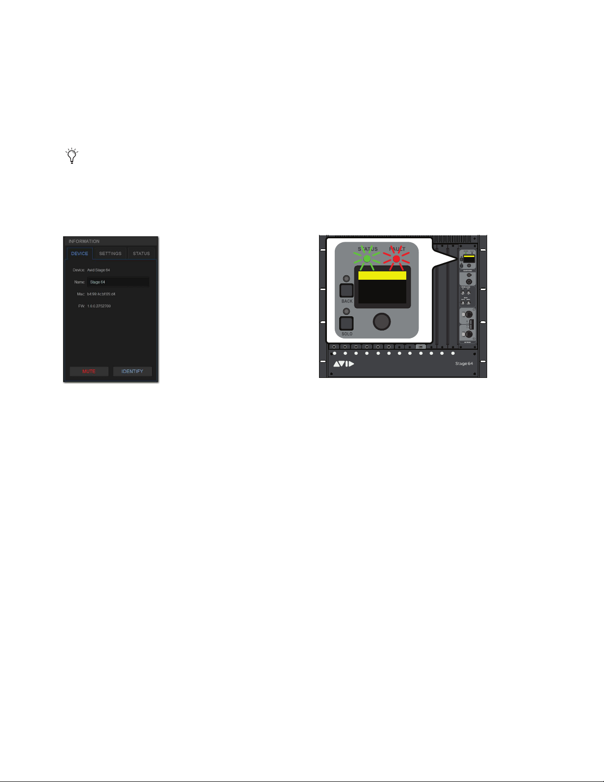
Configuring System Audio 70
Identifying Stage I/O Units
It can be helpful to identify each Stage I/O unit in the Available Devices list before assignment.
To identify Stage I/O units:
1 Make sure your system is in Config mode.
2 On the external screen, go to the Options > Devices page and locate the Available Devices column. All connected and powered
on Stage I/O units are shown in this column.
3 In the Available Devices column, select the top-most Stage 64 so it is outlined in blue. The blue outline indicates that device is
targeted for connection, and is targeted in the Information area of the Devices page.
4 In the Information area, select the Device tab so it is highlighted in blue, then select the Identify button to latch it on.
The Identify button on-screen flashes, and the Status and Fault LEDs on the front panel of the corresponding Stage I/O unit flash.
5 Select Identify again to turn it off.
If any connected Stage I/O units do not appear in the Available Devices section, check network and power connections.
The Identify button (left) and flashing Status and Fault LEDs on the corresponding Stage 64 (right)
ABCD E FGH JKL M
1
2
3
4
5
6
7
8
SIG +48V
SIG +48V
SIG +48V
SIG +48V
SIG +48V
SIG +48V
SIG +48V
SIG +48V
INPUT
SRI-192
1
2
3
4
5
6
7
8
SIG +48V
SIG +48V
SIG +48V
SIG +48V
SIG +48V
SIG +48V
SIG +48V
SIG +48V
INPUT
SRI-192
1
2
3
4
5
6
7
8
SIG +48V
SIG +48V
SIG +48V
SIG +48V
SIG +48V
SIG +48V
SIG +48V
SIG +48V
INPUT
SRI-192
1
2
3
4
5
6
7
8
SIG +48V
SIG +48V
SIG +48V
SIG +48V
SIG +48V
SIG +48V
SIG +48V
SIG +48V
INPUT
SRI-192
1
2
3
4
5
6
7
8
SIG +48V
SIG +48V
SIG +48V
SIG +48V
SIG +48V
SIG +48V
SIG +48V
SIG +48V
INPUT
SRI-192
1
2
3
4
5
6
7
8
SIG +48V
SIG +48V
SIG +48V
SIG +48V
SIG +48V
SIG +48V
SIG +48V
SIG +48V
INPUT
SRI-192
SIG MUTE
MUTE
MUTE
MUTE
MUTE
MUTE
MUTE
MUTE
SIG
SIG
SIG
SIG
SIG
SIG
SIG
OUTPUT
SRO-192
1
2
3
4
5
6
7
8
Home >
<empty-name> 96k
Net OK Mon On
HW OK MADI On
Home >
<Stage 64> 96k
Net OK Mon On
HW OK MADI On
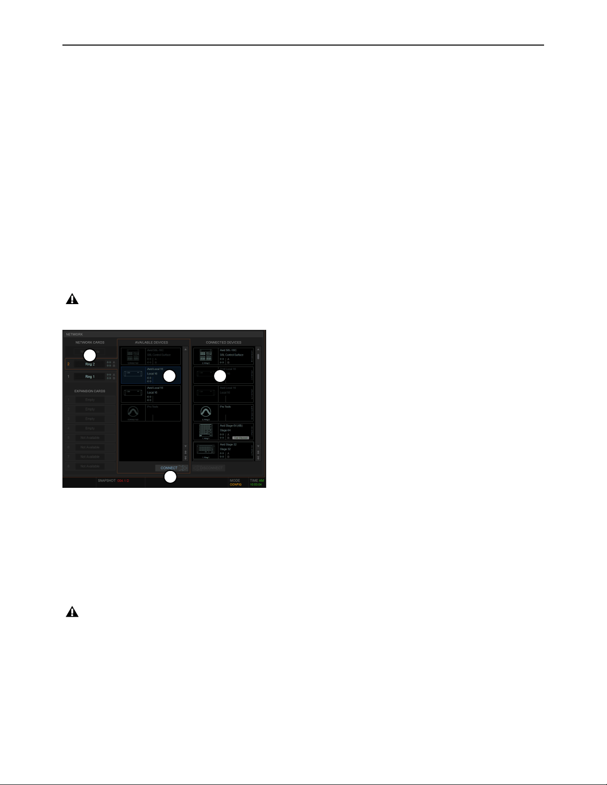
Configuring System Audio 71
Assigning Local 16
Local 16 lets you expand your local I/O capabilities, or add primary local I/O if mixing on the S6L-16C control surface. Each
Local 16 provides 8 analog inputs, 8 analog outputs, 8 AES digital inputs, and 8 AES digital outputs in a compact, 3U rack.
Local 16 requires 2x AVB-192 Network cards be installed in the E6L engine. Unlike Stage I/O, Local 16 units are configured in
the Option > Devices page by connecting them to the
Ring 2 S6L network ring.
To assign Local 16:
1 Make sure the system is in Config Mode (see
Enabling Config Mode).
2 Navigate the external screen to Options > Devices.
3 In the NETWORK CARDS section, select Ring 2.
Ring 2 is only available when a second AVB-192 Network Card is installed in the E6L engine.
4 In the AVAILABLE column, select the first Local 16 device so it is highlighted.
5 Click CONNECT.
6 Click to select a flashing Local 16 slot in the CONNECTED DEVICES column.
7 Repeat for any additional Local 16 units.
8 Shut down your system by doing the following:
• Make sure the system is in Config mode.
• On the external VENUE software screen, go to the Options > System tab.
•Select Shut Down, then select Shut Down again to confirm.
9 Power down all connected components by pressing their back panel power switches to the off (0) positions, and leave all com-
ponents powered-off for at least 30 seconds.
10 Power the components back on in the following order:
• E6L engine
• S6L control surface
• Any connected Stage or local I/O units
11 Wait for the CTMs (if any) to complete their final software update, then proceed to
Setting the System Clock.
On initial power-on after performing a System Restore, firmware updates of the Local 16 units begin just after assigning them.
Figure 2. Assigning Local 16 in Options > Devices
A complete power-cycle is required before using your S6L system.
4
3
6
5
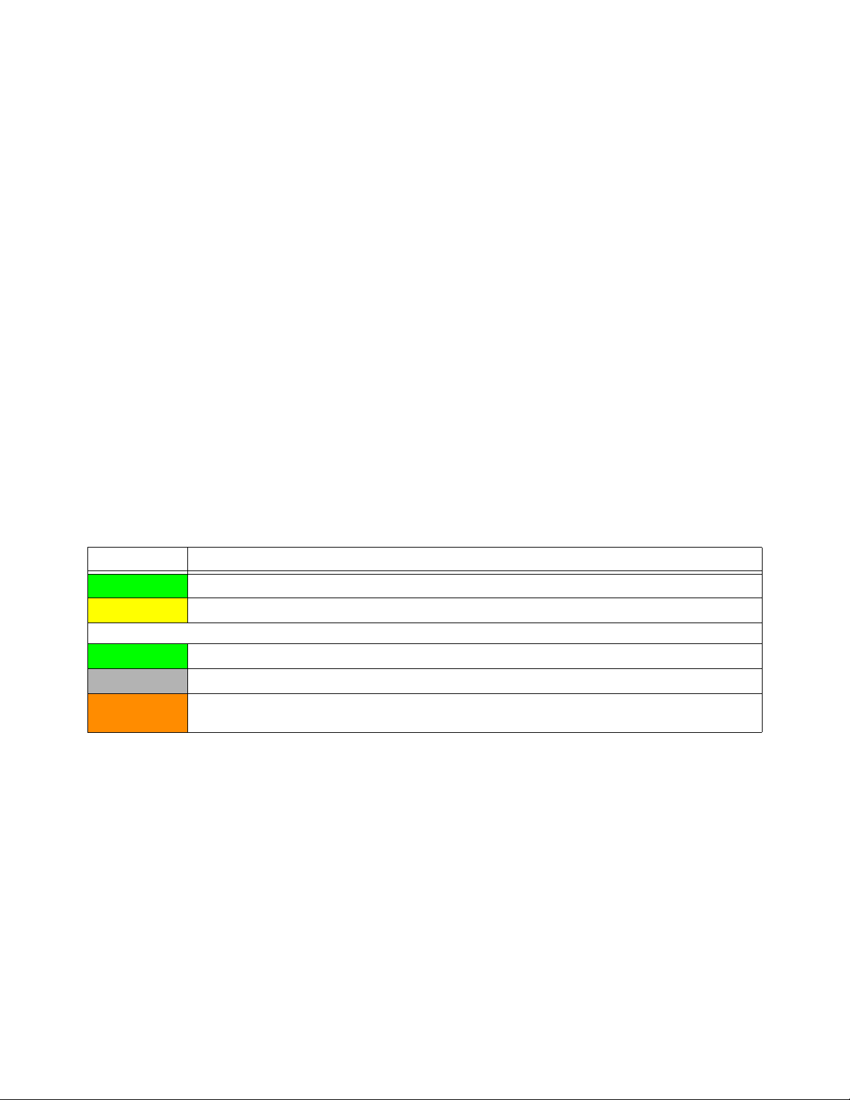
Configuring System Audio 72
Using Master and Slave E6Ls in Shared I/O Configurations
(Input and Output Sharing)
By default, such as when you first configure systems for I/O Sharing, connecting a Stage device to an E6L engine in the
Options > Devices page assigns ownership of all Inputs and Outputs to that E6L (in this context “E6L” is synonymous with “S6L
system”). In the following description, references to Stage 64 also apply to Stage 32 except where noted.
In shared I/O systems, the E6L to which a Stage 64 is assigned becomes the
Input Master of that Stage 64, and other E6Ls on the
network become the Input Slave of that Stage 64. Input Master status determines which E6L can manage shared I/O.
Input Master
When an E6L is the Input Master of a Stage 64, In Master is displayed on the Stage 64 graphic in the Connected De-
vices column on the Options > Devices page. I/O on the Stage 64 is available to be patched to system input and output channels
in the VENUE Patchbay, and the
Stage tabs are highlighted in green to indicate Master status, as is the channel source box on the
Inputs page on a per-channel basis.
• The Input Master system has ownership (control) of all Input slots (A–H) on that Stage 64. Individual Input slots cannot be
assigned to, or controlled by, different systems simultaneously.
• By default, the Input Master system also Claims (controls) all Output slots (J–M) on that Stage 64. The Input Master system
can assign control of Stage outputs to other systems on the network on a per-Output slot (J–M) basis from the Options > De-
vices page (see
Assigning Ownership of Output Slots).
• The Input Master system controls inputs and outputs of Stage 16s (if any). Individual Input or Output slots on each Stage 16
cannot be assigned to, or controlled by, different systems simultaneously.
Input Slave
When an E6L is Slave to a Stage 64 (for example, when another E6L on the network has already assigned a Stage 64),
In Slave is displayed on the Stage 64 graphic(s) in the Connected Devices slot on the Options > Devices page. Stage inputs are
freely available for patching. Stage outputs for that Stage 64 are grayed out in the Patchbay and the outputs are unavailable. The
Stage tabs are highlighted in yellow to indicate Slave status, as is the channel source box on the Inputs page on a per-channel basis.
In the Options > Devices page, Input and Output ownership status is indicated on the image of each device as follows (see also
IO Sharing Example):
In the Patchbay, claimed Output slots are active and available for patching. Waived Output slots are inactive (grayed) but are still
available for patching.
Stored patching to Output slots on any system on the network is unaffected by Output slot ownership. New patching is allowed to
Output slots that are not claimed, similar to other inactive destinations. When an Output patch is reassigned from another patch in
the same Show file, a confirmation dialog is displayed asking you to confirm the new assignment.
Indication and status of Stage devices in I/O Sharing configurations
Indicator
Status
In Master The system is the Input Master for that Stage device.
In Slave A different system is the Input Master for that Stage device.
Reminder: Inputs are controlled globally per Stage device; control of individual Input slots on a Stage device cannot be shared.
Out Claimed The system has claimed control of all Output slots on that Stage device.
Out Waived A different system has claimed, or been assigned, control for all Output slots on that Stage device.
Out Mixed
The system has claimed control of some, but not all, Output slots on that Stage device. A different system also has
control of some, but not all, Output slots on that Stage device.
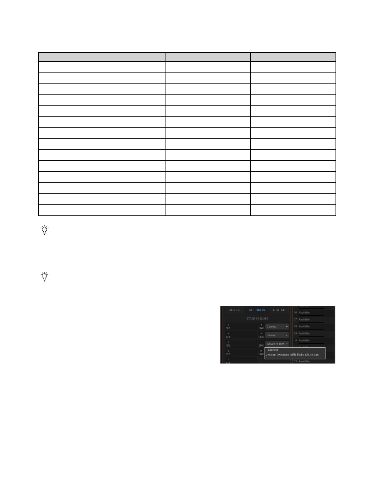
Configuring System Audio 73
Before assigning Stage 64s in shared configurations, you should take into account the following differences in functionality be-
tween Input Master and Input Slave E6Ls for a connected Stage 64 or Stage 16 (as applicable). Unless otherwise noted, function-
ality specified for Stage 64 also applies to Stage 32.
Assigning Ownership of Output Slots
You can assign and reassign Output slot ownership in the Options > Devices page of the current Input Master system.
To reassign Stage Output ownership:
1 On the Input Master system, go to Options > Devices and select a con-
nected Stage 64 on-screen.
2 In the Information section, tap the Settings tab for the currently selected
Stage 64.
Ownership is shown as Claimed or Waived to <E6L Device Name> S6L
system.
3 From the pop-up selector for the desired Output slot, select either of the
following:
• To claim control of that slot, choose
Claim.
• To assign ownership of that slot to a different system on the network, choose Assign Ownership to <E6L Device Name> S6L
system.
Functionality Master E6L Slave E6L
Stage 64 Input Mic Preamp Control Yes (analog gain) Yes (digital trim)
Control of Stage 64 pad
Yes (analog pad) Yes (digital pad)
Control of Stage 64 phantom power Yes No
Gain Tracking n/a Yes
Routing to Stage 64 Outputs Yes No
Routing to/from local IO (Console and Engine I/O) Yes Yes
Patching Stage Inputs to Input Channels Yes Yes
Reordering Input Channels Yes Yes
Mute All Outputs functionality from GUI Yes No
Mute All Outputs status indication Yes Yes
Identify functionality from GUI Yes Yes
Identify status indication Yes Yes
Ability to rename an assigned Stage 64 Yes No
Ability to unassign a Stage 64 Yes No
For example, if you need to connect stage monitors to the Outputs on a particular Stage I/O unit, make sure to assign some or
all Output slots on that Stage I/O unit to the E6L controlling the monitor mix.
Output Slot ownership can only be assigned for Stage 64s or Stage 32s, not for Stage 16s (the Input Master always controls all
Stage 16 Input and Output slots) or Local 16.

Configuring System Audio 74
IO Sharing Example
The following diagrams show how shared Input and Output ownership is indicated on-screen when two example systems are con-
figured for IO Sharing. The two systems share three Stage 64 IO racks. In the diagrams, the corresponding Stage 64 Input and Out-
put slots are shown with matching color outlines:
• System 1 is the Input Master, and controls all inputs on Stage 1 and Stage 2. All inputs on Stage 3 are claimed by System 2.
• System 1 has claimed control of all outputs on Stage 1. All outputs on Stage 2 are assigned to System 2.
• Ownership of outputs on Stage 3 are shared; slots J and K are claimed by system 1, while slots L and M are assigned to system 2.
System 1
The figure below shows how Input and Output ownership is indicated in the Options > Devices page of system 1.
System 2
The figure below shows how Input and Output ownership is indicated in the Options > Devices page of system 2.
Patchbay
The figure below shows how ownership of specific Output slots on Stage 3 is indicated in the Patchbay on each system.
In this example, slots J and K are claimed by system 1 and slots L and M are claimed by system 2.
Indication of Input and Output ownership in Options > Devices for system 1 (shown at left)
Indication of Input and Output ownership in Options > Devices for system 2 (shown at right)
Patchbay, Outputs tab for Stage 3 on system 1 (at left) and system 2 (at right)
ABCD EFGHJKLM
1
2
3
4
5
6
7
8
SIG +48V
SIG +48V
SIG +48V
SIG +48V
SIG +48V
SIG +48V
SIG +48V
SIG +48V
INPUT
SRI-192
1
2
3
4
5
6
7
8
SIG +48V
SIG +48V
SIG +48V
SIG +48V
SIG +48V
SIG +48V
SIG +48V
SIG +48V
INPUT
SRI-192
1
2
3
4
5
6
7
8
SIG +48V
SIG +48V
SIG +48V
SIG +48V
SIG +48V
SIG +48V
SIG +48V
SIG +48V
INPUT
SRI-192
1
2
3
4
5
6
7
8
SIG +48V
SIG +48V
SIG +48V
SIG +48V
SIG +48V
SIG +48V
SIG +48V
SIG +48V
INPUT
SRI-192
1
2
3
4
5
6
7
8
SIG +48V
SIG +48V
SIG +48V
SIG +48V
SIG +48V
SIG +48V
SIG +48V
SIG +48V
INPUT
SRI-192
1
2
3
4
5
6
7
8
SIG +48V
SIG +48V
SIG +48V
SIG +48V
SIG +48V
SIG +48V
SIG +48V
SIG +48V
INPUT
SRI-192
SIG MUTE
MUTE
MUTE
MUTE
MUTE
MUTE
MUTE
MUTE
OUTPUT
SRO-192
1
2
3
4
5
6
7
8
1
2
3
4
5
6
7
8
SIG +48V
SIG +48V
SIG +48V
SIG +48V
SIG +48V
SIG +48V
SIG +48V
SIG +48V
INPUT
SRI-192
SIG +48V
SIG
SIG
SIG
SIG
SIG
SIG
SIG
INPUT
SRI-192
SIG MUTE
MUTE
MUTE
MUTE
MUTE
MUTE
MUTE
MUTE
SIG
SIG
SIG
SIG
SIG
SIG
SIG
OUTPUT
SRO-192
1
2
3
4
5
6
7
8
SIG MUTE
MUTE
MUTE
MUTE
MUTE
MUTE
MUTE
MUTE
SIG
SIG
SIG
SIG
SIG
SIG
SIG
OUTPUT
SRO-192
1
2
3
4
5
6
7
8
SIG MUTE
MUTE
MUTE
MUTE
MUTE
MUTE
MUTE
MUTE
SIG
SIG
SIG
SIG
SIG
SIG
SIG
OUTPUT
SRO-192
1
2
3
4
5
6
7
8
ABCD EFGHJKLM
SIG
SIG
SIG
SIG
MUTE
MUTE
MUTE
MUTE
MUTE
MUTE
MUTE
MUTE
OUTPUT
SRO-192
1
2
3
4
5
6
7
8
SIG MUTE
MUTE
MUTE
MUTE
MUTE
MUTE
MUTE
MUTE
SIG
SIG
SIG
SIG
SIG
SIG
SIG
OUTPUT
SRO-192
1
2
3
4
5
6
7
8
ABCD EFGHJKLM
1
2
3
4
5
6
7
8
SIG +48V
SIG +48V
SIG +48V
SIG +48V
SIG +48V
SIG +48V
SIG +48V
SIG +48V
INPUT
SRI-192
1
2
3
4
5
6
7
8
SIG +48V
SIG +48V
SIG +48V
SIG +48V
SIG +48V
SIG +48V
SIG +48V
SIG +48V
INPUT
SRI-192
1
2
3
4
5
6
7
8
SIG +48V
SIG +48V
SIG +48V
SIG +48V
SIG +48V
SIG +48V
SIG +48V
SIG +48V
INPUT
SRI-192
1
2
3
4
5
6
7
8
SIG +48V
SIG +48V
SIG +48V
SIG +48V
SIG +48V
SIG +48V
SIG +48V
SIG +48V
INPUT
SRI-192
1
2
3
4
5
6
7
8
SIG +48V
SIG +48V
SIG +48V
SIG +48V
SIG +48V
SIG +48V
SIG +48V
SIG +48V
INPUT
SRI-192
1
2
3
4
5
6
7
8
SIG +48V
SIG +48V
SIG +48V
SIG +48V
SIG +48V
SIG +48V
SIG +48V
SIG +48V
INPUT
SRI-192
1
2
3
4
5
6
7
8
SIG +48V
SIG +48V
SIG +48V
SIG +48V
SIG +48V
SIG +48V
SIG +48V
SIG +48V
INPUT
SRI-192
SIG
SIG
SIG
SIG
SIG
SIG
SIG
SIG
INPUT
SRI-192
S
I
G
S
I
G
S
I
G
S
I
G
In Master
In Master
In Slave
Out Claimed
Out Waived
Out Mixed
1 2
Stage 1 Stage 2 Stage 3
ABCD EFGHJKLM ABCD EFGHJKLM
SIG MUTE
MUTE
MUTE
MUTE
MUTE
MUTE
MUTE
MUTE
SIG
SIG
SIG
SIG
SIG
SIG
SIG
OUTPUT
SRO-192
1
2
3
4
5
6
7
8
SIG MUTE
MUTE
MUTE
MUTE
MUTE
MUTE
MUTE
MUTE
SIG
SIG
SIG
SIG
SIG
SIG
SIG
OUTPUT
SRO-192
1
2
3
4
5
6
7
8
SIG MUTE
MUTE
MUTE
MUTE
MUTE
MUTE
MUTE
MUTE
SIG
SIG
SIG
SIG
SIG
SIG
SIG
OUTPUT
SRO-192
1
2
3
4
5
6
7
8
SIG MUTE
MUTE
MUTE
MUTE
MUTE
MUTE
MUTE
MUTE
SIG
SIG
SIG
SIG
SIG
SIG
SIG
OUTPUT
SRO-192
1
2
3
4
5
6
7
8
ABCD EFGHJKLM
1
2
3
4
5
6
7
8
SIG +48V
SIG +48V
SIG +48V
SIG +48V
SIG +48V
SIG +48V
SIG +48V
SIG +48V
INPUT
SRI-192
1
2
3
4
5
6
7
8
SIG +48V
SIG +48V
SIG +48V
SIG +48V
SIG +48V
SIG +48V
SIG +48V
SIG +48V
INPUT
SRI-192
1
2
3
4
5
6
7
8
SIG +48V
SIG +48V
SIG +48V
SIG +48V
SIG +48V
SIG +48V
SIG +48V
SIG +48V
INPUT
SRI-192
1
2
3
4
5
6
7
8
SIG +48V
SIG +48V
SIG +48V
SIG +48V
SIG +48V
SIG +48V
SIG +48V
SIG +48V
INPUT
SRI-192
1
2
3
4
5
6
7
8
SIG +48V
SIG +48V
SIG +48V
SIG +48V
SIG +48V
SIG +48V
SIG +48V
SIG +48V
INPUT
SRI-192
1
2
3
4
5
6
7
8
SIG +48V
SIG +48V
SIG +48V
SIG +48V
SIG +48V
SIG +48V
SIG +48V
SIG +48V
INPUT
SRI-192
1
2
3
4
5
6
7
8
SIG +48V
SIG +48V
SIG +48V
SIG +48V
SIG +48V
SIG +48V
SIG +48V
SIG +48V
INPUT
SRI-192
SIG
SIG
SIG
SIG
SIG
SIG
SIG
SIG
INPUT
SRI-192
SIG MUTE
MUTE
MUTE
MUTE
MUTE
MUTE
MUTE
MUTE
SIG
SIG
SIG
SIG
SIG
SIG
SIG
OUTPUT
SRO-192
1
2
3
4
5
6
7
8
SIG MUTE
MUTE
MUTE
MUTE
MUTE
MUTE
MUTE
MUTE
SIG
SIG
SIG
SIG
SIG
SIG
SIG
OUTPUT
SRO-192
1
2
3
4
5
6
7
8
1 2
In Master
In Slave
In Slave
Out Claimed
Out Waived
Out Mixed
Stage 1 Stage 2 Stage 3
Analog Output (SRO) C
Stage 1 Stage 2 Stage 3
Analog Output (SRO) C Analog Output (SRO) W Analog Output (SRO) W
Analog Output (SRO) C Analog Output (SRO) CAnalog Output (SRO) W Analog Output (SRO) W
Stage 2Stage 2Stage 1 Stage 3
C CWW
1 2

Configuring System Audio 75
The following steps show how you would assign Stage 64 IO ownership to achieve the example configuration.
To configure the IO Sharing Example:
1 Pair each E6L to its S6L control surface.
2 On system 1 go to Options > Devices and do the following:
• Select and Connect Stage 64 1. System 1 becomes the Input Master for Stage 1.
• Select and Connect Stage 64 2. System 1 becomes the Input Master for Stage 2.
• Tap to select Stage 64 2 in the Connected column so it is outlined in blue, then tap the Settings tab in the Information section.
From the pop-up selector for Output slot J, choose Assign Ownership to <E6L Device Name> S6L system (where “E6L De-
vice Name” is the name of the E6L of system 2). Repeat for the remaining Output slots (K, L and M) on Stage 64 2. System 2
now controls all Output slots on Stage 2.
3 On system 2 go to Options > Devices and do the following:
• Select and Connect the Stage 64 3. System 2 becomes the Input Master for Stage 3.
• Tap to select Stage 64 3 in the Connected column so it is outlined in blue, then tap the Settings tab in the Information section.
From the pop-up selector for Output slot J, choose Assign Ownership to <E6L Device Name> S6L system (where “E6L De-
vice Name” is the name of the E6L of system 1). Repeat for Output slot K Stage 64 3. Output slots on Stage 3 are now shared:
System 1 controls Output slots J and K, and system 2 controls Output slots L and M.
4 Proceed to
Setting the System Clock.

Configuring System Audio 76
Setting the System Clock
When you first set up an S6L system (or after a system update or restore), make sure the system clock time, date and time zone are
set appropriately. System Clock is set on the Options page of the external VENUE software screen.
To set the System Clock:
1 On the external screen, select Options, then select the Misc tab.
2 In the System Clock section, select the Format pop-up menu to set the time for-
mat (12 Hour AM/PM or 24 Hour).
3 Select the Edit button in the System Clock section.
4 Select the Zone pop-up to choose the appropriate time zone.
5 Select each available field and enter
the appropriate data to set the time
and date.
6 Select Apply.
The new System Clock settings are
applied.
How to Proceed
• If prompted to activate Windows, refer to the instructions in the VENUE S6L Installation Guide.pdf.
• Make sure you have completed all other steps in the VENUE S6L Installation Guide.pdf to install VENUE plug-ins, optional
software, make optional connections such as Pro Tools and ECx Ethernet Control, and installed and configured Pro Tools and
iLok assets.
• After hardware and software installation is complete, proceed to
Configuring Mains and Mix Buses.
The system clock time can be shown in the Status bar for constant time-of-day display. For more information, see System
Clock.
If necessary, minimize (but do not Cancel) the Windows
Activation alert by touching the down arrow at the
top-right of the dialog.
On touch screens, touch in a field and slide your finger up or down on the screen to increase or decrease the value in the field.
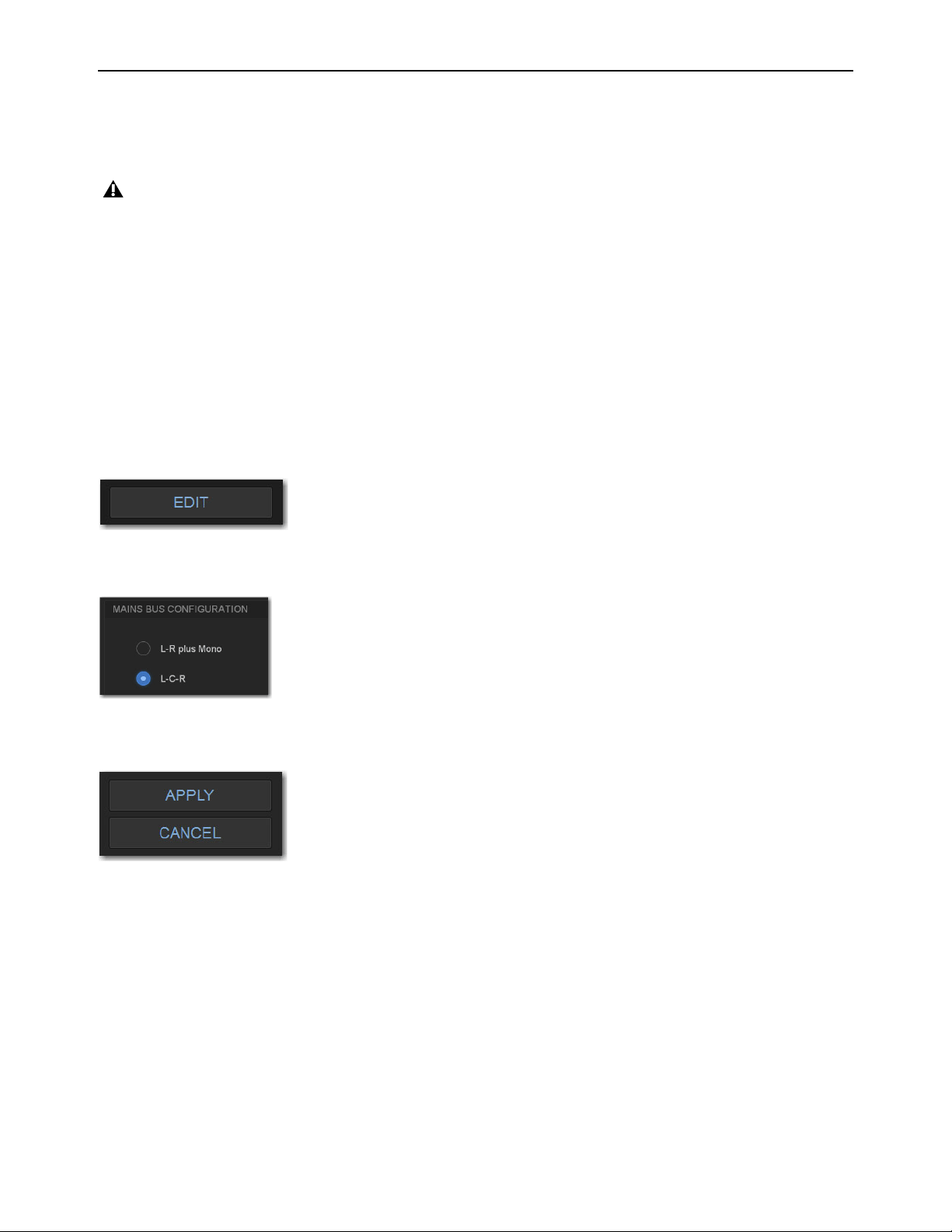
Configuring System Audio 77
Configuring Mains and Mix Buses
After assigning Stage I/O units you can configure the Mains bus and the Mix Buses on your system. Bus configurations are stored
with the Show file, so when you load a different Show file the bus configuration may change if bus configurations in the newly
loaded Show file differ from the previous bus configurations.
Configuring the Mains Bus
The Mains bus can be configured to operate as either of the following:
L–R plus Mono
Pans signals between the left and right channels to the L–R bus, and sums signals to a separate mono bus.
L–C–R
Pans signals across left, center and right channels. You can the amount of center-panned signal that is sent to the center out-
put (see Panning (Mains Center Divergence)).
To configure the Mains bus:
1 Put the system into Config mode.
2 On the external screen, go to Options > System.
3 Select Edit.
4 In the Mains Bus section, select L-R plus Mono or L-C-R.
5 Select Apply (or select Cancel to cancel the operation). The system restarts with the new Mains bus configuration
.
Audio is interrupted when a System Configuration setting is applied. Do not change these settings during a performance.
Options > System Edit button
L-C-R selected as Mains bus configuration
Apply and Cancel buttons.
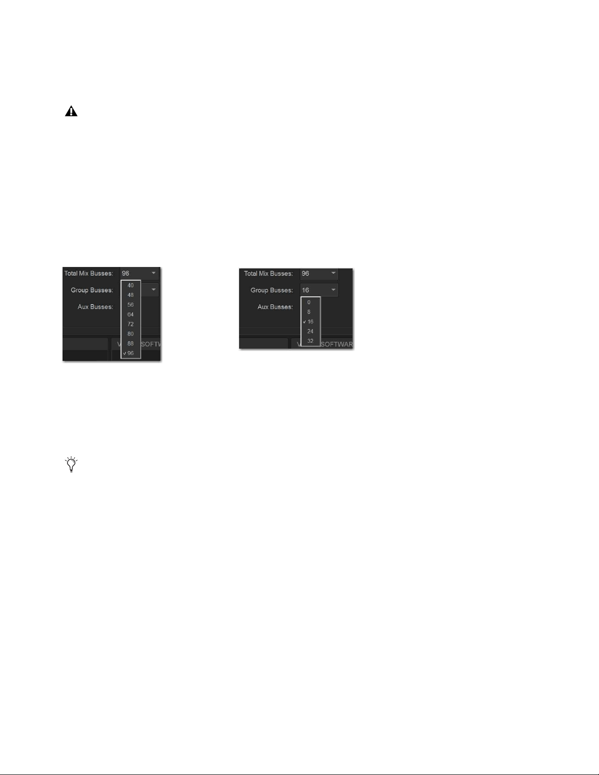
Configuring System Audio 78
Configuring Mix Buses
You can choose the total number of Mix buses available on the system (up to the maximum available Mix buses), and you can con-
figure the Mix buses to provide only Aux buses, or combinations of Aux and Group buses. Setting the number of Mix buses to only
the number you need can reduce clutter on the various screens, but doing so has no effect on processing bandwidth.
To configure the Mix buses:
1 Put the system into Config mode.
2 On the external screen, go to Options > System.
3 Select Edit.
4 Do any of the following:
• From the Total Mix Buses pop-up, chooses the total number of Mix buses you want your system to provide.
• To include Groups in your configuration, from the Group Buses pop-up choose the number of Mix buses you want to desig-
nate as Groups.
5 Select Apply. The system restarts with the new bus configuration.
Data Cleared When Changing Bus Configurations
When the bus configuration is changed, settings for Groups are cleared (or set to default) from all current settings and from all
stored snapshots.
Graphic EQ and/or channel EQ settings may be lost when configuring Mix buses, so save any important EQ settings before re-
configuring. Input Channel, EQ, and Dynamics Presets
Total Mix Buses pop-up menu (left), and the Group Buses pop-up (right)
A new default file OnStagePasswords.example.txt is created on the S6L control surface D: drive whenever the us configura-
tion is changed. This will not change any currently active On-Stage passwords, but the new bus configuration will be reflected
in the newly generated “example” txt file. For more information, see the VENUE On-Stage.pdf.

Configuring System Audio 79
Managing Connections
After initial setup, devices on the network can be named and renamed, reassigned, and removed.
Naming System Components
You can name the S6L control surface, the E6L engine, and any connected and assigned Stage I/O devices. The device name is
stored with the respective device, and stays with that device until it is changed. Names can be changed at any time. Though not re-
quired, naming components is highly recommended.
To name S6L system components:
1 In the Options > Devices tab of the external screen, select the component graphic so it is outlined in blue.
2 In the Information list, select the DEVICE tab.
3 Touch-and-hold (double-click) the field next to Name, then enter a unique name using the keyboard, then press Enter when fin-
ished.
Managing Stage I/O Unit Connections
When power-cycling your system and/or reconnecting Stage I/O devices to the same E6L engine, the original Stage 1–6 assign-
ments are automatically recalled, regardless of the order in which Stage devices are connected. Depending on the hardware com-
binations being used, however, you may want or need to reconfigure system Stage I/O. You can reconfigure Stage I/O on the
Op-
tions > Devices tab any time after the initial system set up and configuration. You can reassign connected Stage I/O racks, remove
Stage I/O racks from the current configuration, and add new Stage I/O racks to the current configuration.
Reassigning a Stage I/O Rack
You can reassign a Stage device to a different Stage slot. For example, for a particular stage setup you may want to rearrange the
order of Stage 64 I/O racks as they appear in the VENUE Patchbay. Or you might want to add one or more Stage 32 or 16 I/O units.
To reassign a Stage I/O unit:
1 Put the system into Config mode.
2 Go to Options > Devices.
3 Select a Stage device in the Connected Devices column, then select the Disconnect button.
The unassigned Stage device appears in the Available Devices column.
4 Re-assign Stage I/O racks as necessary.
Configuring Stage Slots for Stage 16s, Stage 32s, or Stage 64s
When adding Stage 16s or Stage 32s for the first time, or when reconfiguring a system to use Stage 64s instead of Stage 16s or Stage
32s, you must first configure Stage slots before you can assign Stage I/O units in the Options > Devices tab. Each Stage slot cor-
responds to a Stage hardware tab 1–6 in the VENUE Patchbay.
To configure Stage slots and assign Stage 16 I/O racks:
1 Make sure your system is in Config mode.
2 On the external screen, go to the Options > Devices page and locate the Connected Devices column.
In the following sections, references to “Stage I/O devices” includes Stage 64, Stage 32, and Stage 16 (but not Local 16).
You can configure Stage slots and assign devices in VENUE Standalone Software (requires version 5.5 or higher).
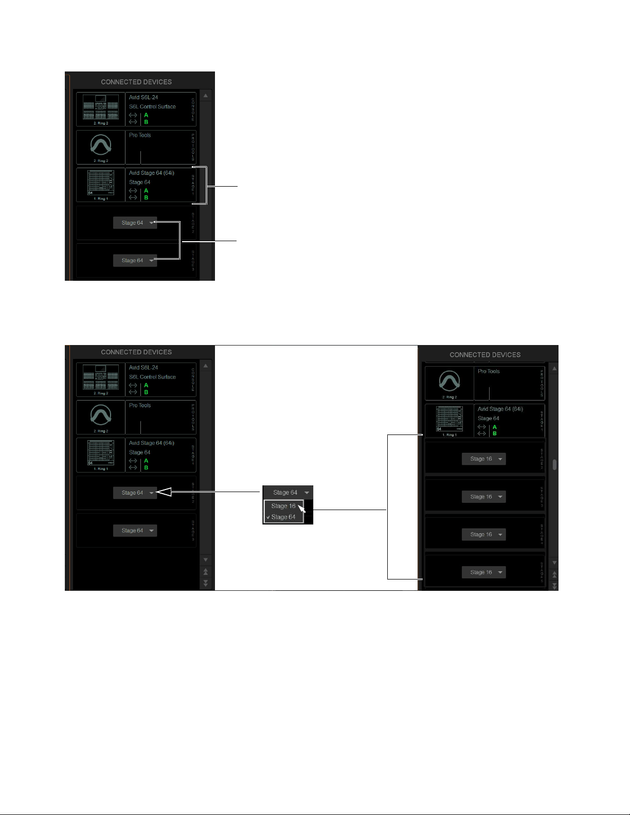
Configuring System Audio 80
By default, three Stage 64 slots are displayed in the Connected Devices column.
3 Select any available slot Type selector and choose Stage 32 or Stage 16 from its pop-up menu.
Up to four Stage 16 slots, or up to two Stage 32 slots, appear in the Connected Devices column.
The number of available Stage slots that appear is determined by the number of connected Stage 64s (if any), allowing for the
maximum supported configurations to be connected. For example, when one or two Stage 64s are already connected configuring
the third available slot to Stage 16 makes four Stage 16 slots become available. When three Stage 64s are already connected, no
additional slots are available.
Connected Devices showing one connected Stage 64 in slot Stage 1 (above), and Stage slot Type selectors in slots 2 and 3 (below)
Stage 16 slots available in Options > Devices
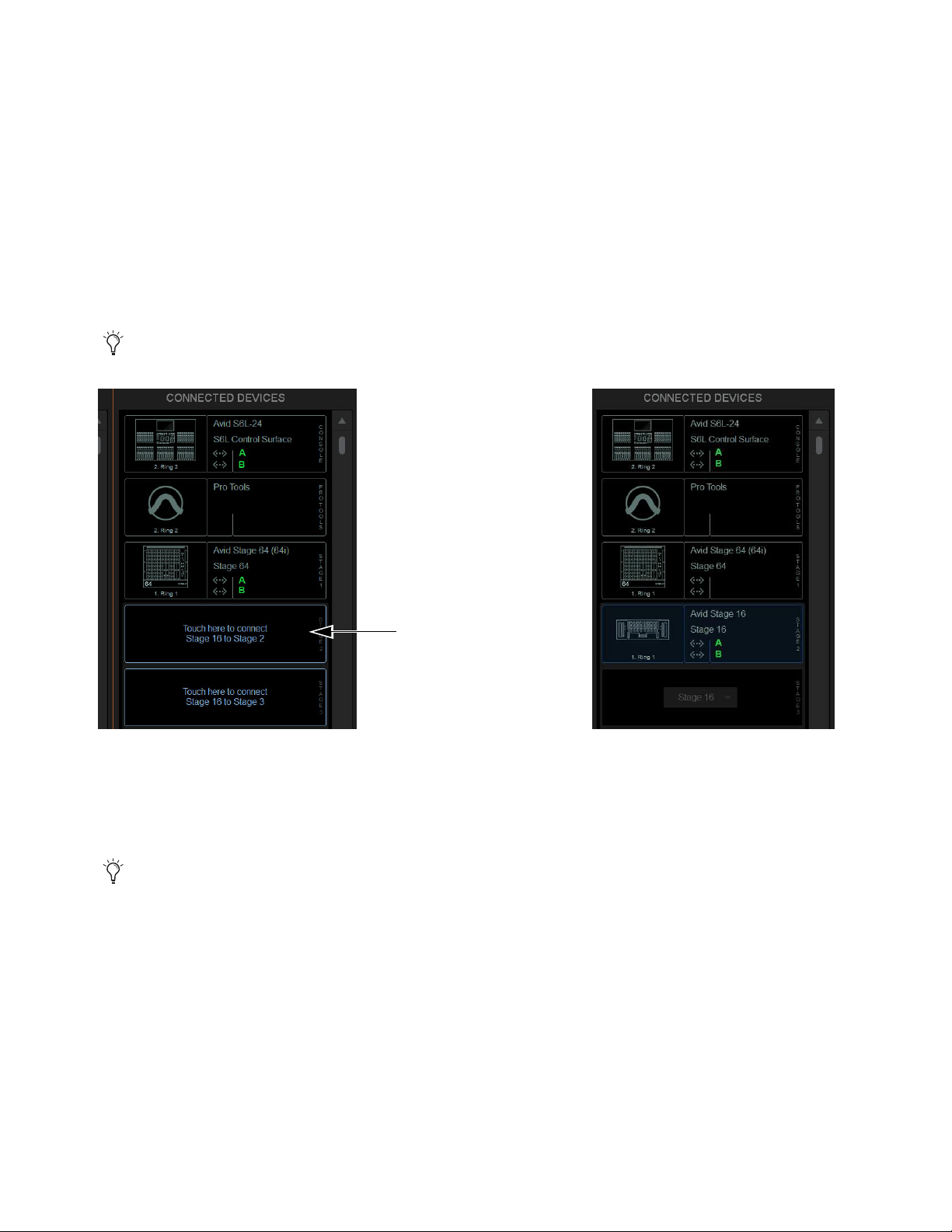
Configuring System Audio 81
Virtual Soundcheck: Important Note
When configuring system audio in Options > Devices, it is recommended to assign
Stage 64s (if any) to the lowest numbered slots 1–3 whenever possible, followed by any Stage 32s, followed by any Stage 16s.The
order of Stage I/O devices in the Connected Devices column does not need to match the order of physical network connections. Slot
designation (
1–6) determines where I/O appears in the Patchbay I/O tabs 1–6, which also determines Virtual Soundcheck channel
order. For example, because each Stage 16 slot occupies 16 channels of Virtual Soundcheck, when switching any slot from Stage
64 to Stage 16 the 4 resulting Stage 16 slots will occupy 64 channels of Virtual Soundcheck. Even if only one Stage 16 I/O unit is
connected and three Stage 16 slots are empty, followed by slot 5 assigned and connected to a Stage 64, the Pro Tools inputs cor-
responding to that Stage 64 will begin at channel 65. To avoid this, it is recommended to assign Stage 64s (if any) to the lowest
numbered slots
1–3 whenever possible, followed by any Stage 32s, followed by any Stage 16s.
4 In the Available Devices column, select the desired Stage I/O device so it is outlined in blue.
5 Select the Connect button at the bottom of the Available Devices column.
6 In the Connected Devices columns, select a flashing Stage 16 slot to assign the selected Stage 16 to that slot.
The Stage slot is populated with the selected Stage 16, and the I/O on that Stage 16 is now available to be patched to system input
and output channels in the VENUE Patchbay under the corresponding Stage 1–6 hardware tab. For more information on using
the Patchbay, see the VENUE S6L System Guide.pdf.
7 Assign any other available Stage I/O racks as desired.
You can also right-click on the desired Stage device in the Available Devices column and assign it by selecting an available slot.
Flashing Stage slots in the Connected Devices column (left) and a Stage 16 assigned to Stage slot 2 (right)
You can reassign Stage I/O units at any time after initial software installation, and after all necessary firmware updates are
completed. If you are replacing Stage units with one of a different type, simply select and Disconnect the unwanted Stage I/O
unit in the Connected Devices list, re-assign the corresponding Stage slot if necessary, then assign the desired Stage I/O units.

Configuring System Audio 82
Removing a Stage I/O Rack
You can unassign a Stage I/O rack from your configuration. Do this if you are removing a connected Stage device from your con-
figuration, or if a Stage device from a previous configuration is not connected and you want to dismiss warning dialogs.
To remove a Stage device from the current configuration:
1 Put the system into Config mode.
2 Go to Options > Devices.
3 Do either of the following depending on the status of the Stage device:
• To remove a connected Stage device, select that device in the Connected Devices column and choose Disconnect.
• To remove a Stage device that is not connected (indicated by a greyed-out Stage device in the Connected Devices list), touch
and hold (right-click) the grayed-out Stage device and choose Forget missing Stage device.
The I/O for that Stage device is now grayed-out under the corresponding Stage 1–3 hardware tab in the Patchbay.
Managing S6L–E6L Connections in Shared I/O Configurations
After the initial setup, the next time you power on your S6L system an S6L will automatically attempt to reconnect to the most re-
cently assigned E6L. This allows for a specific S6L to always be paired with a specific E6L. The command Forget Engine is pro-
vided to manage subsequent S6L–E6L connections.
Forget Engine
Lets you disconnect the currently connected E6L from the S6L control surface. This command is useful if you have
multiple E6Ls and S6Ls that may or may not be used together regularly.
To disconnect an E6L from an S6L:
1 Enable Config Mode (see
Enabling Config Mode).
2 Go to the Options > Devices page.
3 Right-click the E6L Engine graphic and choose Forget Engine.
On subsequent restarts, the S6L will not attempt to pair with any E6Ls on the network. Any pairings to an E6L must be made man-
ually (see
Pairing the E6L and S6L).
Managing E6L–Stage I/O Connections in Shared I/O Configurations
After the initial setup, the next time you power on your system the previous Master/Slave relationships between Stage 64s and E6Ls
are maintained. If the E6L Input Master for a given Stage 64 in the network is not detected or is lost, the following dialogs are pre-
sented on the other E6L:
Master Engine Not Detected
Appears when the E6L Input Master in the previous configuration is either not powered on or is not
connected.
Master Engine Lost
Appears if the E6L Input Master is disconnected from the network, for example if the audio network connec-
tion is broken or the Master E6L loses power.
In both cases, you can choose to either maintain the current Master/Slave relationship and continue to operate as if the Master E6L
were still online (if, for example, the Master E6L has lost power), or become the Master of any Slave Stage 64s (if, for example,
you do not expect the former E6L Master to come back online). If you choose the latter option, Stage 64s must be reassigned as de-
scribed in
Reassigning a Stage I/O Rack.
Reclaiming Output Slot Ownership
Disconnecting and reconnecting a Stage 64 or Stage 32 from/to the Input Master system lets you choose whether to recall the pre-
vious ownership assignments, or to claim all Output slots.
When reconnecting the same Stage 64 or Stage 32 to the same Stage slot on the Input Master system, a dialog appears that lets you
choose to either recall Output ownership from the previous configuration, or to claim the Stage Rack as a new Stage Rack and claim
all Output slots by the Input Master system.

Configuring System Audio 83
Choose either of the following in the Reconnecting Shared Stage Rack dialog:
Yes
Connects the Stage Rack and restores Output slot ownership assignment to match the previous configuration.
No
Connects the Stage Rack and claims all Output slots.
Show File Compatibility
Loading Show files is unaffected by Output ownership, and functions the same as when loading Show files onto systems configured
for Shared Stage Input.
How to Proceed
To get started learning how to use the control surface, see any of the following:
• Banking Channels on the S6L Control Surface
• Selecting and Attentioning Channels
• Adjusting Channel Parameters
For overviews of the system components, see any of the following:
• S6L Control Surface Overview
• E6L Engine Overview
• Stage and Local I/O Rack Overview
To learn more about the external VENUE software screen, see External VENUE Software Screen Overview.
The S6L system comes pre-loaded with Demo show files, which offer preset system configurations for some of the most common
mixing scenarios. See
Loading a Show for instructions on loading Show files.
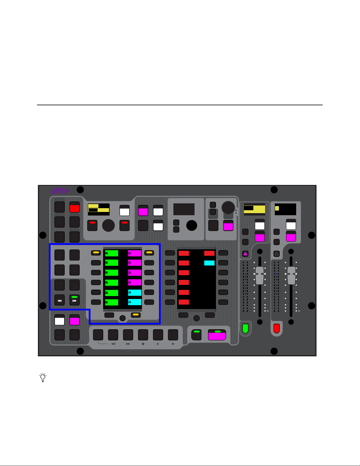
Banking Channels on the S6L Control Surface 84
Banking Channels on the S6L Control Surface
This chapter covers banking system channels to the channel strips on the S6L control surface, spilling Auxes, Groups and VCAs,
creating and using custom fader layouts (User Layouts), and using Bank Safe.
Channel Banking Overview
The Master Live Module (MLM) provides channel banking controls to navigate to channels beyond the number of available phys-
ical channel strips. The banking controls on the S6L control surface let you:
• Bank a combination of input and output channels (see
Banking a Combination of Inputs and Outputs)
• Bank only custom fader layouts, VCAs, input channels, or output channels (see
Banking Only User Layouts, VCAs, Inputs,
or Outputs)
• Create and recall custom fader layouts (see
User Layouts)
• Bank Safe channels, letting you “lock” channels to a fader (see
Bank Safing Channels)
Banking controls on the MLM
You can also bank channels to the external screen fader strips using on-screen tabs and buttons. See
Viewing Pages and
Tabs. Banking channels on the external screen is independent of control surface banking.
VENUE | S6L
Solo Solo
Home
Config
VCAs
Outputs
Layouts
Inputs
Flip
Recall
Trans
F1 F2 F3 F4 F5
NEXT
PREV
Store
Y
X
Y
X
AFL
Dim
In
Sel
SNAPSHOTS
Talk
Back
Multi
Select
Encoder
Assign
Select
Clear
Tap
Tempo
Multi
Assgn
Default Fine
OK Cancel
Over
Write
Mix to
Mon
Solo
Clear
60
40
30
20
10
5
0
6
12
60
40
30
20
10
5
0
6
12
8All
Preview
ASSIGNABLE ENCODER MONITORING
Push A/BHold SIP
SHIFT
ALT
CTRL
ESC
Mute Mute
A
B
Nom
30
21
15
9
3
0
3
9
15
30
21
15
9
3
0
3
9
15
Inputs/Outputs
Next
Global Cont
rols
0.0 dB
L
Left
0.0 dB
Kick
Mute Group 1
Mute Group
Function KeysMute Group 2
Mute Group 3
Mute Group 4
Mute Group 5
Mute Group 6
M1
M2
M3
M4
M5
M6
001/011
reset all inputs
0.0 dB
CH 1
Kick
Ch 1-16
1-16
Aux 1-8
1-8
Aux 9-16
Aux 17-24
Aux 25-32
25-32
VCA 1-8
1-8
VCA 9-16
9-16
Ch 17-32
17-32 9-16
Ch 33-48
33-48 17-24
Ch 49-64
49-64
Ch 65-80
65-80
Ch 81-96
81-96
S1Cu2
001 3
P:S1C1
N:S1C3
S1Cu3
S1Cu2
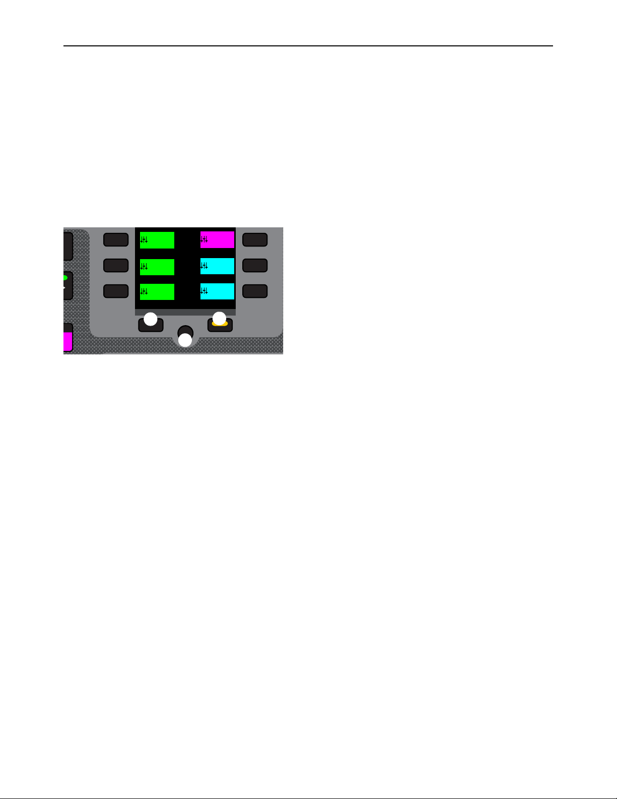
Banking Channels on the S6L Control Surface 85
Banking a Combination of Inputs and Outputs
Split Banking Mode
Split Banking mode, the default banking mode for the S6L control surface, lets you bank a combination of input and output chan-
nels to the S6L channel strips using pre-defined banks of channels. Split Banking mode banks input channels sequentially to the
faders below the Channel Knob Modules (CKMs), and banks output channels sequentially to the faders below the Master Live
Module (MLM). The Left Soft Keys menu shows the pre-defined channel banks, which you bank to the faders using the corre-
sponding Soft Keys. Multiple pages of channels banks are provided, which you can navigate using the Left Soft Keys display nav-
igation switches.
Navigating the Left Soft Keys Display in Split Banking Mode
Split Banking mode provides multiple pages of channel banks you can choose to bank to the faders. The Previous and Next Page
switches, and the Home switch let you navigate the available pages of channel banks.
1 – Previous Switch
2 – Next Switch
3 – Home Switch
To access to the previous or next page of available channel configurations:
Press a lit Previous or Next switch until you locate the channels you wish to access.
The switches are lit when there is a previous or next page of channel configurations available.
To return to the first page of available channel configurations:
Press the lit HOME switch.
Left Soft Keys display navigation switches
p
Next
Aux 25-32
25-32
VCA 1-8
1-8
VCA 9-16
9-16
Ch 49-64
49-64
Ch 65-80
65-80
Ch 81-96
81-96
1
2
3
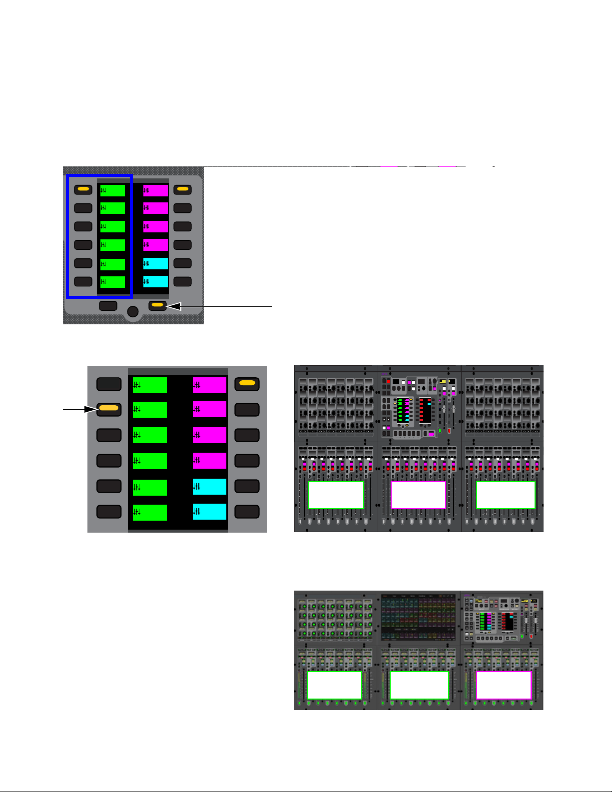
Banking Channels on the S6L Control Surface 86
Banking Inputs in Split Banking Mode
In Split Banking mode, input channels appear in the left-hand column of the Left Soft Keys display. The S6L-32D provides 24 in-
put channels per bank, S6L-24D/24C provide 16 input channels per bank, and S6L-16C provide 8.
To bank input channels in Split Banking mode:
1 Make sure the Layouts, VCAs, Inputs, or Outputs switches are unlit/not selected. If one is selected, press it so it is unlit.
2 In the left-hand column of the Left Soft Keys display, locate the input channels you want to bank to the faders.
• Or press the lit Next switch until you see the desired channel configuration in the display.
3 Press the corresponding Soft Key so it lights. The selected set of input channels are banked to the faders below the CKMs.
On S6L-24C, the MLM is at the far right above faders 17–24. Banking to input channels 17–32 on 24C places those channels
on faders 1–16.
Left Soft Keys display showing the first page of Split Banking mode channel configurations, and a lit Next switch
The selected Soft Key (left) and how the selected configuration of channels is banked to faders of an S6L-24D (right)
Selected configuration of channels banked to fader on S6L-24C
YY
60
40
30
20
10
5
0
6
12
60
40
30
20
10
5
0
6
12
Nom
30
21
15
9
3
0
3
9
15
30
21
15
9
3
0
3
9
15
Inputs/Outputs
Next
Global Cont
rols
Mute Group 1
Mute Group
Function KeysMute Group 2
Mute Group 3
Mute Group 4
Mute Group 5
Mute Group 6
M1
M2
M3
M4
M5
M6
Ch 1-16
1-16
Aux 1-8
1-8
Aux 9-16
Aux 17-24
Aux 25-32
25-32
VCA 1-8
1-8
VCA 9-16
9-16
Ch 17-32
17-32 9-16
Ch 33-48
33-48 17-24
Ch 49-64
49-64
Ch 65-80
65-80
Ch 81-96
81-96
s
21
15
9
3
0
3
9
15
Inputs/Outputs
Next
Global Cont
rols
Mute Group 1
Mute Group
Function KeysMute Group 2
Mute Group 3
Mute Group 4
Mute Group 5
Mute Group 6
M1
M2
M3
M4
M5
M6
Ch 1-16
1-16
Aux 1-8
1-8
Aux 9-16
Aux 17-24
Aux 25-32
25-32
VCA 1-8
1-8
VCA 9-16
9-16
Ch 17-32
17-32 9-16
Ch 33-48
33-48 17-24
Ch 49-64
49-64
Ch 65-80
65-80
Ch 81-96
81-96
60
40
30
20
10
5
0
6
12
60
40
30
20
10
5
0
6
12
Select
Solo
Select
Solo
Select
Solo
Select
Solo
Select
Solo
Select
Solo
Select
Solo
Select
Solo
BAS
Menu Safe
Mute
Y
X
Y
X
Y
X
Y
X
Y
X
Y
X
Y
X
Y
X
BAS
Menu Safe
Mute
BAS
Menu Safe
Mute
BAS
Menu Safe
Mute
BAS
Menu Safe
Mute
BAS
Menu Safe
Mute
BAS
Menu Safe
Mute
BAS
Menu Safe
Mute
60
40
30
20
10
5
0
6
12
60
40
30
20
10
5
0
6
12
60
40
30
20
10
5
0
6
12
60
40
30
20
10
5
0
6
12
60
40
30
20
10
5
0
6
12
60
40
30
20
10
5
0
6
12
60
30
21
15
9
3
0
3
9
15
60
30
21
15
9
3
0
3
9
15
60
30
21
15
9
3
0
3
9
15
60
30
21
15
9
3
0
3
9
15
60
30
21
15
9
3
0
3
9
15
60
30
21
15
9
3
0
3
9
15
60
30
21
15
9
3
0
3
9
15
60
30
21
15
9
3
0
3
9
15
Nom
60
40
30
20
10
5
0
6
12
60
40
30
20
10
5
0
6
12
Select
Solo
Select
Solo
Select
Solo
Select
Solo
Select
Solo
Select
Solo
Select
Solo
Select
Solo
BAS
Menu Safe
Mute
Y
X
Y
X
Y
X
Y
X
Y
X
Y
X
Y
X
Y
X
BAS
Menu Safe
Mute
BAS
Menu Safe
Mute
BAS
Menu Safe
Mute
BAS
Menu Safe
Mute
BAS
Menu Safe
Mute
BAS
Menu Safe
Mute
BAS
Menu Safe
Mute
60
40
30
20
10
5
0
6
12
60
40
30
20
10
5
0
6
12
60
40
30
20
10
5
0
6
12
60
40
30
20
10
5
0
6
12
60
40
30
20
10
5
0
6
12
60
40
30
20
10
5
0
6
12
60
30
21
15
9
3
0
3
9
15
60
30
21
15
9
3
0
3
9
15
60
30
21
15
9
3
0
3
9
15
60
30
21
15
9
3
0
3
9
15
60
30
21
15
9
3
0
3
9
15
60
30
21
15
9
3
0
3
9
15
60
30
21
15
9
3
0
3
9
15
60
30
21
15
9
3
0
3
9
15
Nom
MIXMIXMIXPLUG-INSDYNAMICSEQINPUTCHANNEL
In
Sel
In
Sel
In
Sel
In
Sel
In
Sel
In
Sel
In
Sel
In
Sel
In
Sel
In
Sel
In
Sel
In
Sel
In
Sel
In
Sel
In
Sel
In
Sel
In
Sel
In
Sel
In
Sel
In
Sel
In
Sel
In
Sel
In
Sel
In
Sel
In
Sel
In
Sel
In
Sel
In
Sel
In
Sel
In
Sel
In
Sel
In
Sel
MIXMIXMIXPLUG-INSDYNAMICSEQINPUTCHANNEL
In
Sel
In
Sel
In
Sel
In
Sel
In
Sel
In
Sel
In
Sel
In
Sel
In
Sel
In
Sel
In
Sel
In
Sel
In
Sel
In
Sel
In
Sel
In
Sel
In
Sel
In
Sel
In
Sel
In
Sel
In
Sel
In
Sel
In
Sel
In
Sel
In
Sel
In
Sel
In
Sel
In
Sel
In
Sel
In
Sel
In
Sel
In
Sel
VENUE | S6L
Solo Solo
Home
Config
VCAs
Outputs
Layouts
Inputs
Flip
Recall
Trans
F1 F2 F3 F4 F5
NEXT
PREV
Store
Y
X
Y
X
AFL
Dim
In
Sel
SNAPSHOTS
Talk
Back
Multi
Select
Encoder
Assign
Select
Clear
Tap
Temp o
Multi
Assgn
Default Fine
OK Cancel
Over
Write
Mix to
Mon
Solo
Clear
60
40
30
20
10
5
0
6
12
60
40
30
20
10
5
0
6
12
8All
Preview
ASSIGNABLE ENCODER MONITORING
Push A/BHold SIP
SHIFT
ALT
CTRL
ESC
Mute Mute
A
B
Nom
30
21
15
9
3
0
3
9
15
30
21
15
9
3
0
3
9
15
Inputs/Outputs
Next
Global Controls
0.0 dB
L
Left
0.0 dB
Kick
Mute Group 1
Mute Group
Function KeysMute Group 2
Mute Group 3
Mute Group 4
Mute Group 5
Mute Group 6
M1
M2
M3
M4
M5
M6
0
01/011
reset all inputs
0.0 dB
CH 1
Kick
Ch 1-16
1-16
Aux 1-8
1-8
Aux 9-16
Aux 17-24
Aux 25-32
25-32
VCA 1-8
1-8
VCA 9-16
9-16
Ch 17-32
17-32 9-16
Ch 33-48
33-48 17-24
Ch 49-64
49-64
Ch 65-80
65-80
Ch 81-96
81-96
Inputs 17-24 Inputs 25-32Auxes 1-8
Inputs 17-24 Inputs 25-32 Auxes 1-8
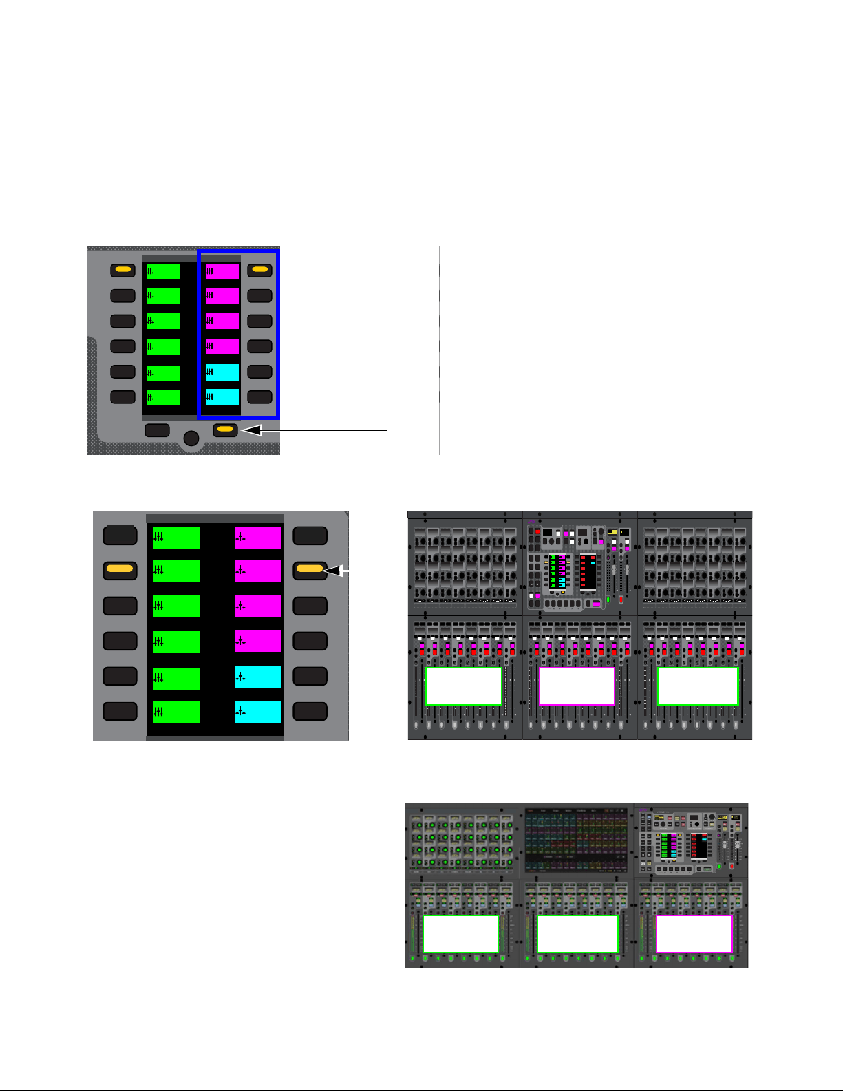
Banking Channels on the S6L Control Surface 87
Banking Outputs in Split Banking Mode
In Split Banking mode, outputs channels appear in the right-hand column of the Left Soft Keys display. All S6L control surface
models provide eight output channels per bank. The type and number of Aux and Group output channels available for banking de-
pend on the overall Mix Bus configuration as set in the Options > System page of the external screen.
To bank output channels in Split Banking mode:
1 Make sure the Layouts, VCAs, Inputs, or Outputs switches are not selected (unlit). If one is selected, press it so it is unlit.
2 In the right-hand column of the Left Soft Keys display, locate the output channels you want to bank to the faders.
• Or press the lit Next switch until you see the desired channel configuration in the display.
3 Press the corresponding Soft Key so it lights. The selected set of output channels are banked to the faders below the MLM.
On S6L-24C, banking to Auxes 9–16 places those channels on faders 17–24 and on S6L-16C to faders 9–16.
Left Soft Keys display showing the first page of Split Banking mode channel configurations, and a lit Next switch
The selected Soft Key (left) and how the selected channels are banked to faders of an S6L-24D (right)
Selected configuration of channels banked to fader on S6L-24C
Inputs/Outputs
Next
Global Controls
Mute Group 1
Mute Group
Function KeysMute Group 2
Mute Group 3
Mute Group 4
Mute Group 5
Mute Group 6
M1
M2
M3
M4
M5
M6
Ch 1-16
1-16
Aux 1-8
1-8
Aux 9-16
Aux 17-24
Aux 25-32
25-32
VCA 1-8
1-8
VCA 9-16
9-16
Ch 17-32
17-32 9-16
Ch 33-48
33-48 17-24
Ch 49-64
49-64
Ch 65-80
65-80
Ch 81-96
81-96
60
40
30
20
10
5
0
6
12
21
15
9
3
0
3
9
15
Inputs/Outputs
Next
Global Cont
rols
Mute Group 1
Mute Group
Function KeysMute Group 2
Mute Group 3
Mute Group 4
Mute Group 5
Mute Group 6
M1
M2
M3
M4
M5
M6
Ch 1-16
1-16
Aux 1-8
1-8
Aux 9-16
Aux 17-24
Aux 25-32
25-32
VCA 1-8
1-8
VCA 9-16
9-16
Ch 17-32
17-32 9-16
Ch 33-48
33-48 17-24
Ch 49-64
49-64
Ch 65-80
65-80
Ch 81-96
81-96
60
40
30
20
10
5
0
6
12
60
40
30
20
10
5
0
6
12
Select
Solo
Select
Solo
Select
Solo
Select
Solo
Select
Solo
Select
Solo
Select
Solo
Select
Solo
BAS
Menu Safe
Mute
Y
X
Y
X
Y
X
Y
X
Y
X
Y
X
Y
X
Y
X
BAS
Menu Safe
Mute
BAS
Menu Safe
Mute
BAS
Menu Safe
Mute
BAS
Menu Safe
Mute
BAS
Menu Safe
Mute
BAS
Menu Safe
Mute
BAS
Menu Safe
Mute
60
40
30
20
10
5
0
6
12
60
40
30
20
10
5
0
6
12
60
40
30
20
10
5
0
6
12
60
40
30
20
10
5
0
6
12
60
40
30
20
10
5
0
6
12
60
40
30
20
10
5
0
6
12
60
30
21
15
9
3
0
3
9
15
60
30
21
15
9
3
0
3
9
15
60
30
21
15
9
3
0
3
9
15
60
30
21
15
9
3
0
3
9
15
60
30
21
15
9
3
0
3
9
15
60
30
21
15
9
3
0
3
9
15
60
30
21
15
9
3
0
3
9
15
60
30
21
15
9
3
0
3
9
15
Nom
60
40
30
20
10
5
0
6
12
60
40
30
20
10
5
0
6
12
Select
Solo
Select
Solo
Select
Solo
Select
Solo
Select
Solo
Select
Solo
Select
Solo
Select
Solo
BAS
Menu Safe
Mute
Y
X
Y
X
Y
X
Y
X
Y
X
Y
X
Y
X
Y
X
BAS
Menu Safe
Mute
BAS
Menu Safe
Mute
BAS
Menu Safe
Mute
BAS
Menu Safe
Mute
BAS
Menu Safe
Mute
BAS
Menu Safe
Mute
BAS
Menu Safe
Mute
60
40
30
20
10
5
0
6
12
60
40
30
20
10
5
0
6
12
60
40
30
20
10
5
0
6
12
60
40
30
20
10
5
0
6
12
60
40
30
20
10
5
0
6
12
60
40
30
20
10
5
0
6
12
60
30
21
15
9
3
0
3
9
15
60
30
21
15
9
3
0
3
9
15
60
30
21
15
9
3
0
3
9
15
60
30
21
15
9
3
0
3
9
15
60
30
21
15
9
3
0
3
9
15
60
30
21
15
9
3
0
3
9
15
60
30
21
15
9
3
0
3
9
15
60
30
21
15
9
3
0
3
9
15
Nom
60
40
30
20
10
5
0
6
12
60
40
30
20
10
5
0
6
12
Select
Solo
Select
Solo
Select
Solo
Select
Solo
Select
Solo
Select
Solo
Select
Solo
Select
Solo
BAS
Menu Safe
Mute
Y
X
Y
X
Y
X
Y
X
Y
X
Y
X
Y
X
Y
X
BAS
Menu Safe
Mute
BAS
Menu Safe
Mute
BAS
Menu Safe
Mute
BAS
Menu Safe
Mute
BAS
Menu Safe
Mute
BAS
Menu Safe
Mute
BAS
Menu Safe
Mute
60
40
30
20
10
5
0
6
12
60
40
30
20
10
5
0
6
12
60
40
30
20
10
5
0
6
12
60
40
30
20
10
5
0
6
12
60
40
30
20
10
5
0
6
12
60
40
30
20
10
5
0
6
12
60
30
21
15
9
3
0
3
9
15
60
30
21
15
9
3
0
3
9
15
60
30
21
15
9
3
0
3
9
15
60
30
21
15
9
3
0
3
9
15
60
30
21
15
9
3
0
3
9
15
60
30
21
15
9
3
0
3
9
15
60
30
21
15
9
3
0
3
9
15
60
30
21
15
9
3
0
3
9
15
Nom
MIXMIXMIXPLUG-INSDYNAMICSEQINPUTCHANNEL
In
Sel
In
Sel
In
Sel
In
Sel
In
Sel
In
Sel
In
Sel
In
Sel
In
Sel
In
Sel
In
Sel
In
Sel
In
Sel
In
Sel
In
Sel
In
Sel
In
Sel
In
Sel
In
Sel
In
Sel
In
Sel
In
Sel
In
Sel
In
Sel
In
Sel
In
Sel
In
Sel
In
Sel
In
Sel
In
Sel
In
Sel
In
Sel
MIXMIXMIXPLUG-INSDYNAMICSEQINPUTCHANNEL
In
Sel
In
Sel
In
Sel
In
Sel
In
Sel
In
Sel
In
Sel
In
Sel
In
Sel
In
Sel
In
Sel
In
Sel
In
Sel
In
Sel
In
Sel
In
Sel
In
Sel
In
Sel
In
Sel
In
Sel
In
Sel
In
Sel
In
Sel
In
Sel
In
Sel
In
Sel
In
Sel
In
Sel
In
Sel
In
Sel
In
Sel
In
Sel
VENUE | S6L
Solo Solo
Home
Config
VCAs
Outputs
Layouts
Inputs
Flip
Recall
Trans
F1 F2 F3 F4 F5
NEXT
PREV
Store
Y
X
Y
X
AFL
Dim
In
Sel
SNAPSHOTS
Talk
Back
Multi
Select
Encoder
Assign
Select
Clear
Tap
Tempo
Multi
Assgn
Default Fine
OK Cancel
Over
Write
Mix to
Mon
Solo
Clear
60
40
30
20
10
5
0
6
12
60
40
30
20
10
5
0
6
12
8All
Preview
ASSIGNABLE ENCODER MONITORING
Push A/BHold SIP
SHIFT
ALT
CTRL
ESC
Mute Mute
A
B
Nom
30
21
15
9
3
0
3
9
15
30
21
15
9
3
0
3
9
15
Inputs/Outputs
Next
Global Controls
0.0 dB
L
Left
0.0 dB
Kick
Mute Group 1
Mute Group
Function KeysMute Group 2
Mute Group 3
Mute Group 4
Mute Group 5
Mute Group 6
M1
M2
M3
M4
M5
M6
0
01/011
reset all inputs
0.0 dB
CH 1
Kick
Ch 1-16
1-16
Aux 1-8
1-8
Aux 9-16
Aux 17-24
Aux 25-32
25-32
VCA 1-8
1-8
VCA 9-16
9-16
Ch 17-32
17-32 9-16
Ch 33-48
33-48 17-24
Ch 49-64
49-64
Ch 65-80
65-80
Ch 81-96
81-96
Inputs 17-24 Inputs 25-32Auxes 9-16
Inputs 17-24 Inputs 25-32 Auxes 9-16
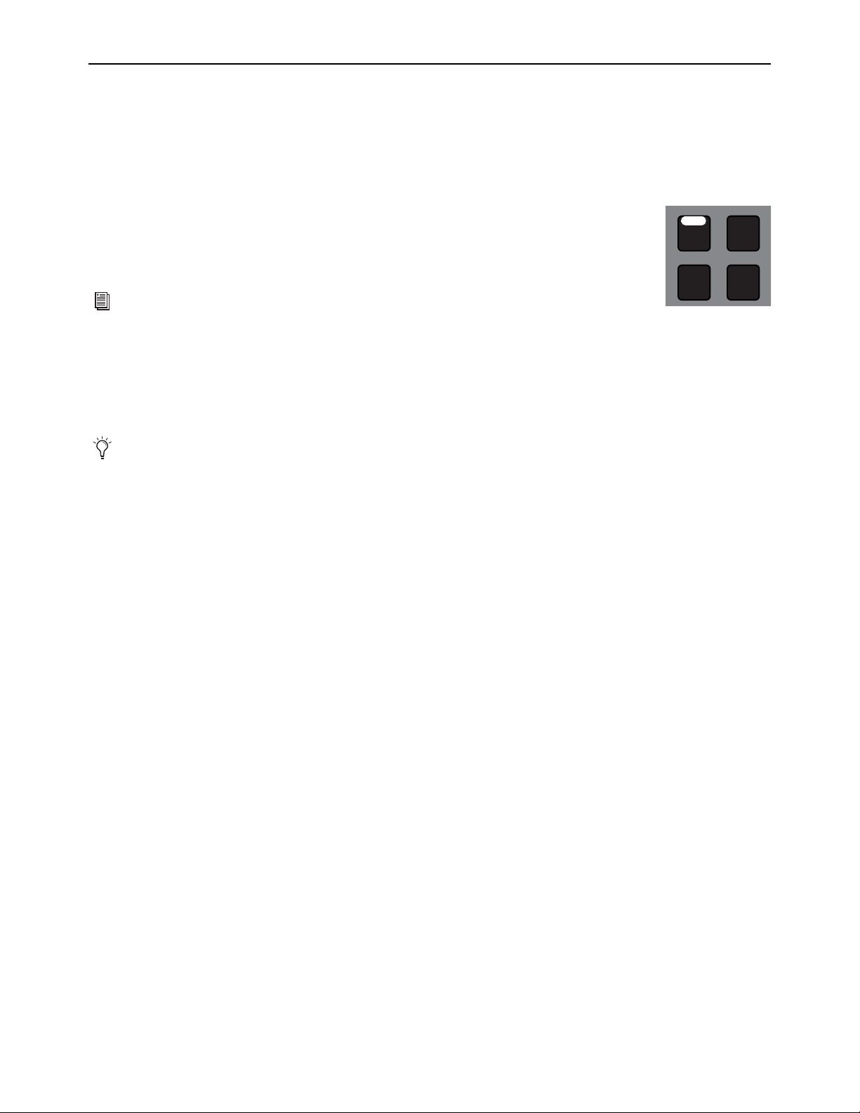
Banking Channels on the S6L Control Surface 88
Banking Only User Layouts, VCAs, Inputs, or Outputs
Fader Bank Mode
You can bank only certain types of channels to the faders using the Fader Bank Mode switches. Pressing a Fader Bank Mode switch
banks only the selected type of channels to all faders on the control surface. The Left Soft Keys display shows the available banks
of channels, which you bank using the corresponding Soft Keys. You can also use the Horizontal Banking switches to nudge the
currently banked channels.
To bank a User Layout in Fader Bank mode:
Press Layouts so it lights.
If you have not created your own custom User Layouts, the default User Layout is banked to all faders
on the control surface.
To bank VCAs in Fader Bank mode:
1 Press the VCA Fader Bank mode switch so it lights.
VCAs 1–16 (S6L-16C), 1–24 (S6L-24D/24C), or 1–32 (S6L-32D) are banked to all the faders on the control surface.
2 To bank to other VCAs, such as VCAs 25–32 on the S6L-24D/24C, press the corresponding Soft Key.
• Or use the Horizontal Banking switches to nudge channels left or right (see
Banking Horizontally (Nudging Channels).
To bank input channels in Fader Bank mode:
1 Press the Inputs Fader Bank Mode switch so it lights.
Input channels 1–16 (S6L-16C), 1–24 (S6L-24D/24C), or 1–32 (S6L-32D) are banked to all the faders on the control surface.
2 In the Left Soft Keys display, locate the input channels you want to bank to the faders. Only input channels are shown in the dis-
play.
3 Press the corresponding Soft Key to bank the desired channels to all faders on the control surface.
• Or use the Horizontal Banking switches to nudge channels left or right.
To bank output channels in Fader Bank mode:
1 Press the Outputs Fader Bank Mode switch.
Auxes 1–16 (S6L-16C), 1–24 (S6L-24D/24C), or 1–32 (S6L-32D) are banked to all the faders on the control surface.
2 In the Left Soft Keys display, locate the output channels you want to bank to the faders. Auxes, Groups when applicable, Ma-
trixes, and Mains are shown in the display.
3 Press the corresponding Soft Key to bank the desired channels to all faders on the control surface.
• Or use the Horizontal Banking switches to nudge channels left or right.
To exit Fader Bank mode, do any of the following:
Press a lit Fader Bank Mode switch. The last Split Banking mode channel configuration is restored to the faders.
Press Home.
For instructions on creating your own User Layouts, see
User Layouts.
If you navigate out of Fader Bank mode, the next time you enable Fader Bank mode the previous banking configuration will be
recalled for the selected channel type.
VCAs
Outputs
Layouts
Inputs
8All
Fader Bank mode
switches
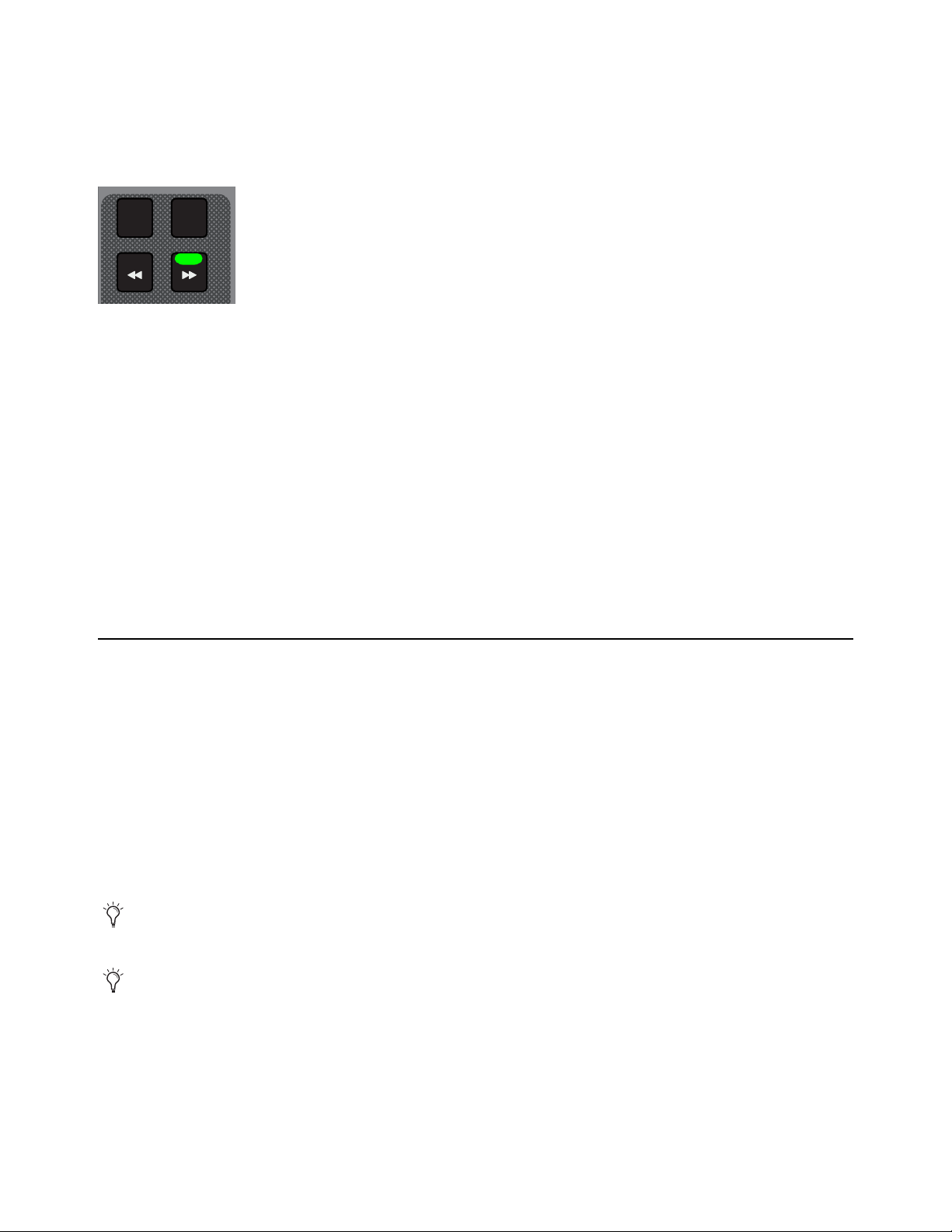
Banking Channels on the S6L Control Surface 89
Banking Horizontally (Nudging Channels)
The Horizontal Banking switches, available when Fader Bank mode is enabled, let you sequentially nudge channels to the left or
right one channel at a time, one fader bank (eight channels) at a time, or all fader banks (16 channels for S6L-16C, 24 channels for
S6L-24D/24C, or 32 channels for S6L-32D) at a time. When Fader Bank mode is enabled, depending on the type of channels cur-
rently banked to the faders, the
<< and/or >> switches light to indicate the direction in which you can nudge channels.
To nudge channels to the left or right by one channel:
Press a lit << or >> switch. The Soft Keys LEDs for the active banks of channels flash to indicate that channels from both banks
are contributing to the current banking configuration.
To nudge channels to the left or right one fader bank (eight channels):
1 Press the 8 switch so it lights.
2 Press a lit << or >> switch. The Soft Keys LEDs for the active banks of channels flash to indicate that channels from both banks
are contributing to the current banking configuration.
To nudge channels to the left or right 24 (for S6L-24D/24C) or 32 (for S6L-32D) channels:
1 Press the All switch so it lights.
2 Press a lit << or >> switch. The Soft Keys LED for the next or previous bank of channels lights to indicate that those channels
are banked to the control surface’s faders.
Spill Mode for Outputs
Spill mode lets you rapidly access channels assigned to an Aux or Group output bus, Matrix, or VCA, without needing to navigate
through fader banks on the console. Spill mode can be activated from the fader strip for an Output master, or from Universe view.
To spill from the Output strip:
Double tap the attention key of the desired Aux, Group, Matrix, or VCA.
To spill from the Universe view:
1 Navigate the MTS (or external screen on S6L-16C) Universe view to the Matrix, Auxes, Groups, or VCAs page.
2 Tap to enable the Spill icon.
3 Touch an Aux, Group, Matrix, or VCA tile. The members of that output are spilled to the faders.
4 When an output is spilled, attentioning any other Output spills that output.
To exit (unspill), do any of the following:
• Press the attention key of the spilled output.
• Select a fader Banking mode (such as Inputs, Outputs, Layouts, or VCAs).
• On the MLM, press
Spill so it is disabled (or press Cancel).
• Press Exit Spill on the external GUI banner.
Horizontal Banking switches
You can control how the spilled master is or isn’t banked when spilling using the
Position Safe When Spilling setting.
For Auxes, see also
Adjusting Aux Sends on Faders (Sends on Faders Mode).
8All
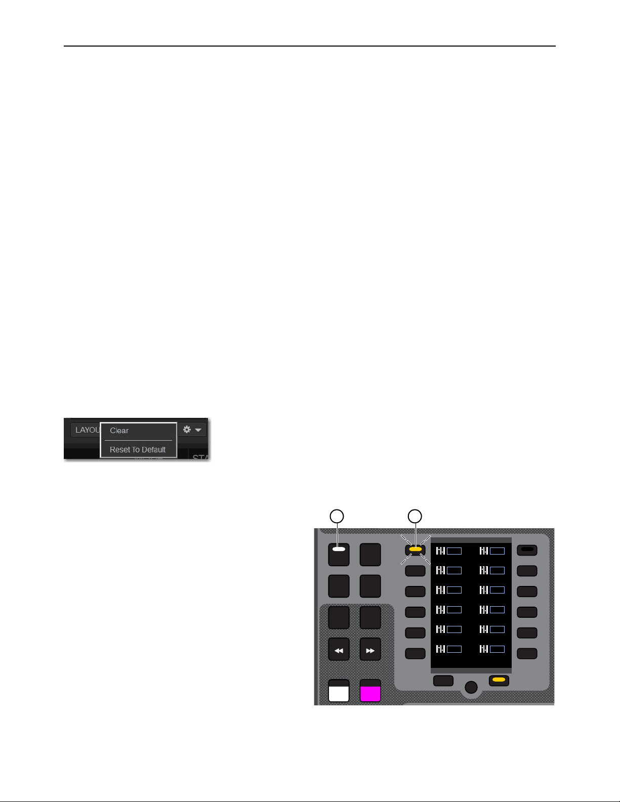
Banking Channels on the S6L Control Surface 90
User Layouts
You can create custom fader Layouts and s access those channels on the S6L channel strips using the Layouts switch and left
Soft Key bank on the MLM, providing the following features and capabilities:
• Store a single Layout in a snapshot (as available in previous versions of VENUE software).
• Save up to 23 additional Layouts within a single Show file, and assign Layouts to MLM Soft Keys, separate from snapshots.
• Name, recall and edit Layouts.
User Layouts can include any type of channel in any order of any format, up to the maximum number of fader strips on the control
surface (such as 16 on S6L-16C, 24 on S6L-24D/24C and 32 on S6L-32D). Each User Layout can be saved as a discrete User Lay-
out preset file. You can also store and recall one User Layout per snapshot.
Assigning Channels to a User Layout
You can assign channels to a User Layout using the S6L control surface or the external screen. You can assign individual channels
or multiple channels using Multi-Assign. Channels are arranged from left to right in the User Layout in the order in which they are
assigned. You can then reorder them using drag-and-drop (see Reordering Channels Using Drag and Drop).
Clearing a User Layout
When you first launch an S6L system, or load a Demo Show file included with the system, the default User Layout (Layout 1) is
loaded. You may want to clear the default User Layout before creating your own.
To clear the default User Layout
1 On the external screen, go to the Inputs or Outputs page and select the Layouts tab. Make sure the default User Layout (Layout
1) is either recalled or selected in the list.
2 Tap-and-hold (right-click) any fader strip and select User Layout from the pop-up menu, then choose Reset Layout.
• Or, select the Gear icon under the User Layout members list and choose Clear from the menu. If Layout 1 is selected, choose
Reset to Default.
Creating Layouts Using the S6L Control Surface
To create and assign Layouts using the MLM Soft Keys:
1 On the MLM, press the Layouts switch.
The last recalled Layout (or the default Layout if no custom
Layouts exist) banks to all faders on the control surface.
2 Press and hold a Soft Key for two or more seconds. In the
image at right, Soft Key 1 (Layout 1) is selected.
The Channel Color switch under fader strip 1 flashes red,
indicating it is ready for channel assignment.
To choose a different fader strip for assignment, press its
Channel Color switch so it flashes red.
3 To select a channel to assign to the currently targeted fader
strip, do either of the following:
• Tap a channel tile in the Universe of the MTS. The chan-
nel tile is bordered in orange.
• Press a channel
Attention switch.
The Channel Color switch on the next fader strip flashes red.
Layouts Gear icon menu
VCAs
Outputs
Layouts
Inputs
Flip
Encoder
Assign
8All
Layouts
Next
Layout 1
L 1
Layout 2
L 2
Layout 3
L 3
Layout 4
L 4
Layout 5
L 5
Layout 6
L 6
Layout 7
L 7
Layout 8
L 8
Layout 9
L 9
Layout 10
L
10
Layout 11
L
11
Layout 12
L
12
1 2
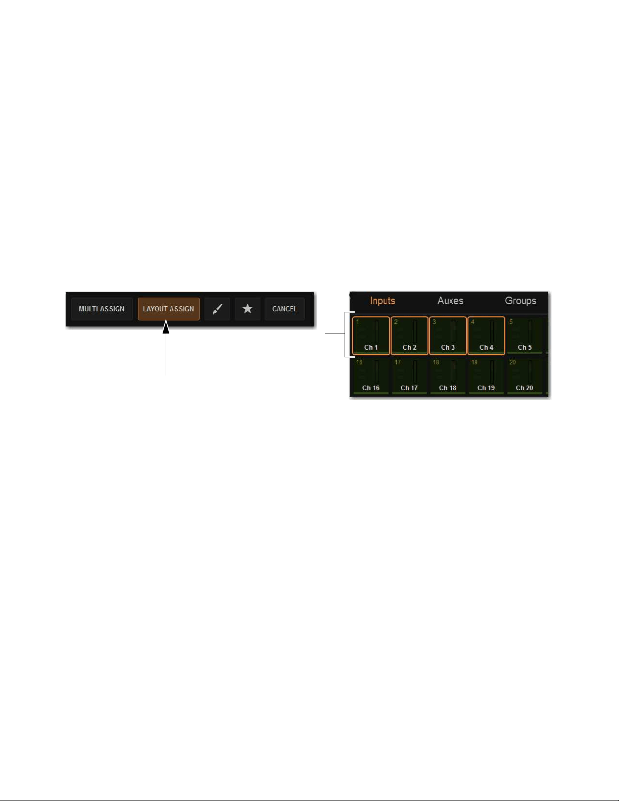
Banking Channels on the S6L Control Surface 91
4 Repeat the previous steps to assign additional channels to fader strips.
5 When finished, do any of the following:
• To save the Layout and exit Layout Assign mode, tap OK on the MTS or external screen.
• To save the Layout but remain in Layouts Assign mode, press a different Layouts Soft Key.
• To exit without saving the new Layout, tap
Cancel on the MTS or external screen.
To navigate the Soft Keys to other Layouts:
Press the Prev or Next Soft Keys below the Left Soft Keys bank.
Creating Layouts Using the Universe View
To assign channels to the User Layout using the Universe view:
1 On the MTS (or external screen on S6L-16C), touch Universe to show the Universe view.
2 Tap LAYOUT ASSIGN so it lights. The S6L system enters User Layout Assignment Mode. Channels assigned to the current or
most recently selected User Layout are indicated on the control surface as follows:
• Channel Tiles for the currently assigned channels are bordered in orange on the MTS.
•
Attention switches for currently assigned channels flash.
3 Tap a Channel Type button (Inputs, Auxes, Groups, Matrixes, VCAs, or Mains) to show those channels on the MTS, or Bank
the desired channels to the channel strips.
4 Tap a channel tile. The channel tile is bordered in orange.
– or –
• Press a channel Attention switch. The Attention switch flashes.
5 Repeat to assign any other channels, navigating to other channel banks as necessary.
6 To remove a channel from the User Layout, do either of the following:
• Tap a Channel Tile that is bordered in orange so the orange border disappears.
• Press a channel Attention switch so it is no longer flashing.
7 Tap Layout Assign (or press Multi-Assign on the MLM) so it is unlit to exit User Layout Assignment mode.
Your User Layout assignments are saved.
8 If desired, store the User Layout as a Preset. See
Working with User Layout Presets.
Enabled Layout Assign button (left) and Channel Tiles showing channels currently assigned to the User Layout

Banking Channels on the S6L Control Surface 92
Creating and Editing Layouts Using the External Screen
To assign a channel to a User Layout using the external screen:
1 Depending on the type of channel you want to assign, go to the Inputs or Outputs page.
2 Touch and hold (right-click) a fader strip on-screen, and select User Layout from the pop-up menu.
3 In the User Layout sub-menu, choose the channel strip to which you want to assign the channel.
4 Repeat for any other channels you want to assign.
5 If desired, store the User Layout as a Preset. See
Working with User Layout Presets.
To remove channels from a User Layout using the external screen.
1 Go to the Inputs or Outputs page.
2 Select the Layouts tab.
3 To remove a single channel from a User Layout:
• Tap-and-hold (right-click) any fader strip and select User Layout from the pop-up menu.
• Choose Clear Chanel <x>: <channel name>.
To reset a User Layout:
Do either of the following:
• Tap-and-hold (right-click) any fader strip, select User Layout from the pop-up menu, and then choose Reset Layout.
• Select the Gear icon under the User Layout members list and choose Clear from the menu. If the default User Layout (Layout
1) is currently recalled or selected in the list, choose Reset to Default.
User Layout sub-menu
External screen Layouts tab (right)
Clear User Layout Assignments menu items

Banking Channels on the S6L Control Surface 93
Banking the User Layout
You can bank the User Layout from the control surface or the external screen.
To bank User Layouts to the channel strips on the control surface:
1 On the MLM, press the Layouts Fader Banking Mode switch.
The last recalled Layout (or the default Layout if no custom Layouts exist) banks to all faders on the control surface. The left
bank of MLM Soft Keys display all available User Layouts.
2 Press a Soft Key to bank the corresponding User Layout.
Channels assigned to the current User Layout are banked to the channel strips. User Layout strips that have no channel assignments
are blank. Any stereo channels are assigned to a single fader, as are the three Mains buses (see
Using Mains in a User Layout).
Working with User Layout Presets
You can store the current User Layout to disk as a preset file. One User Layout is stored to a preset file. You can then load a User
Layout saved as a preset file. After you load a preset file, you can then bank the newly loaded User Layout.
To store a User Layout as a preset file:
1 Assign channels to the User Layout as desired.
2 On the external screen, go to the Inputs or Outputs page and select the LAYOUTS tab.
3 Below the User Layout Members list, select the Presets Folder icon on-screen to open the User Layouts Presets Folder.
4 Choose User Presets folder from the Folder pop-up menu at the top of the Presets window.
To store the current User Layout as a new preset:
Select New and enter a name for the preset file. The current User Layout is stored as a User Layout preset.
To preview an existing preset:
Select the preset name in the Presets window so it is highlighted. The selected User Layout is visible on the external screen Lay-
outs tab, but is not yet loaded.
To load the currently selected preset:
Press Enter on the keyboard or press OK in the Presets window title bar.
To immediately load a preset and close the Presets window:
Double-tap the preset.
To cancel without loading the preset.
Select Cancel.
User Layout Presets folder icon
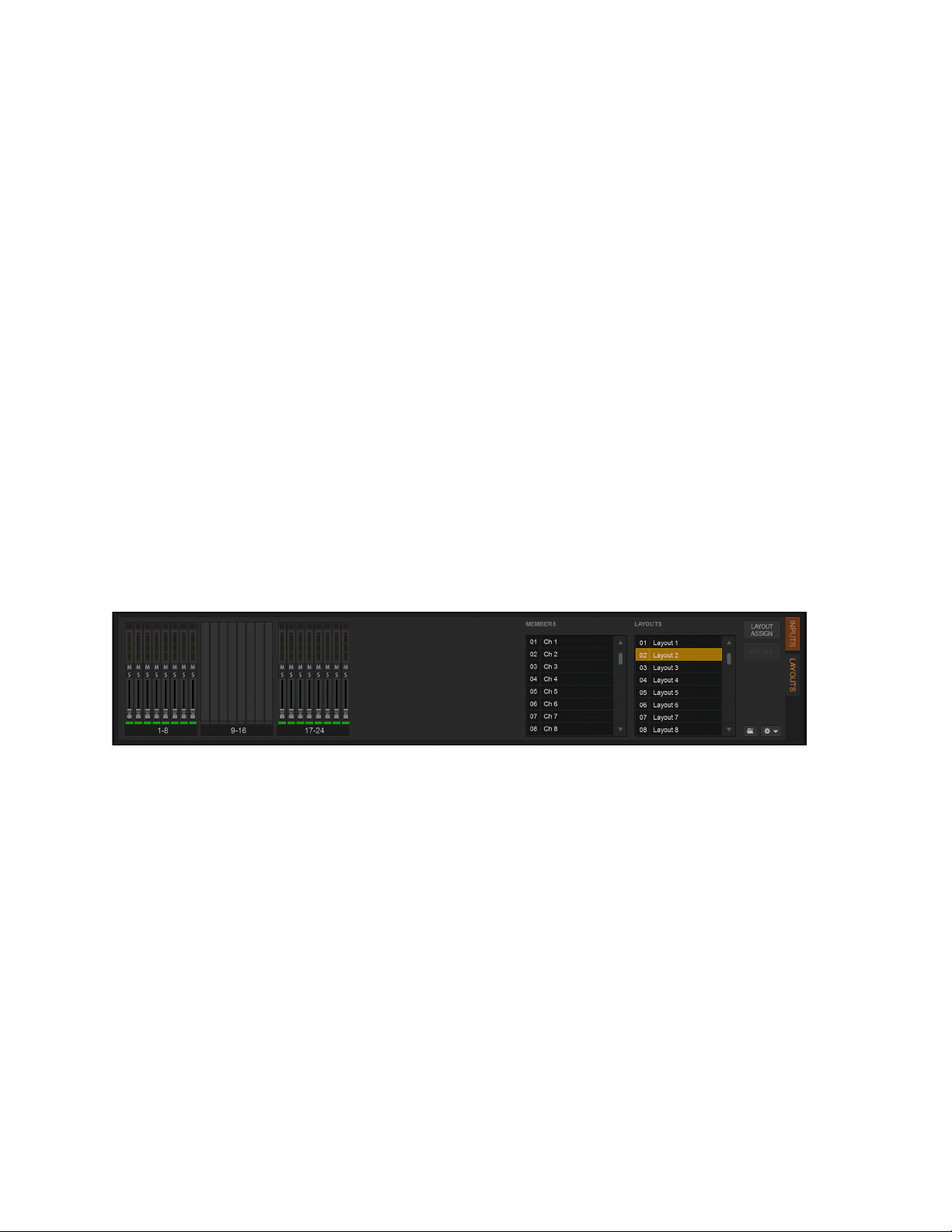
Banking Channels on the S6L Control Surface 94
Examples of Creating and Editing Layouts
The following two examples show how to create a Layout that includes blank strips, and how to modify an existing Layout by re-
moving three assigned channels.
Example 1: Creating a Layout with Blank Strips
The following example shows how to create and save a custom Layout consisting of channels 1–8, 8 blank strips, and channels
9–16. This custom Layout will be assigned to MLM Soft Key 2.
To create and store Layouts:
1 Select Layouts Fader Banking Mode.
2 Press and hold Layout Soft Key 2 for two or more seconds.
The Layout already assigned to Soft Key 2 loads, the Channel Color switch on fader strip 1 flashes red, and Layout Soft Key 2
flashes. If no Layout is assigned to the selected Soft Key, an empty Layout is recalled (all faders darken and move to –inf),
3 Select Channel 1 on the MTS.
Fader strip 1 populates with Channel 1, and the Channel Color switch on fader 2 flashes red indicating it is ready for channel as-
signment.
4 Repeat Step 3 to assign channels 2–8 to fader strips 2–8.
5 Press the Channel Color switch on fader 17.
The Channel Color switch on fader 17 flashes red.
6 Repeat Step 3 to assign channels 9–16 to fader strips 17–24.
7 On the MLM, press OK.
The new Layout is stored to Soft Key 2, and the Soft Key 2 switch LED lights solid indicating it is the currently loaded Layout.
On the external screen, the Layouts tab shows the currently loaded Layout.
Modifying a Custom Layout
The following example shows how to modify an existing custom Layout assigned to Soft Key 6, to clear faders 9, 10, and 11.
To modify a stored custom Layout:
1 Select Layouts Fader Banking Mode.
2 Press and hold Layout Soft Key 6.
Faders populate with Layout 6. The Channel Color switch on fader strip 1 flashes red, and Layout Soft Key 6 flashes.
3 Press and hold the Channel Color switch on fader strip 9.
Fader strip 9 clears (it darkens and its fader resets to -inf), and its Channel Color switch flashes red.
4 Repeat Step 3 to clear fader strips 10 and 11.
5 On the MLM, press OK.
The modified Layout is stored to Soft Key 6 which lights solid.
Layouts view showing channels assigned to faders 1-8 and 17-24
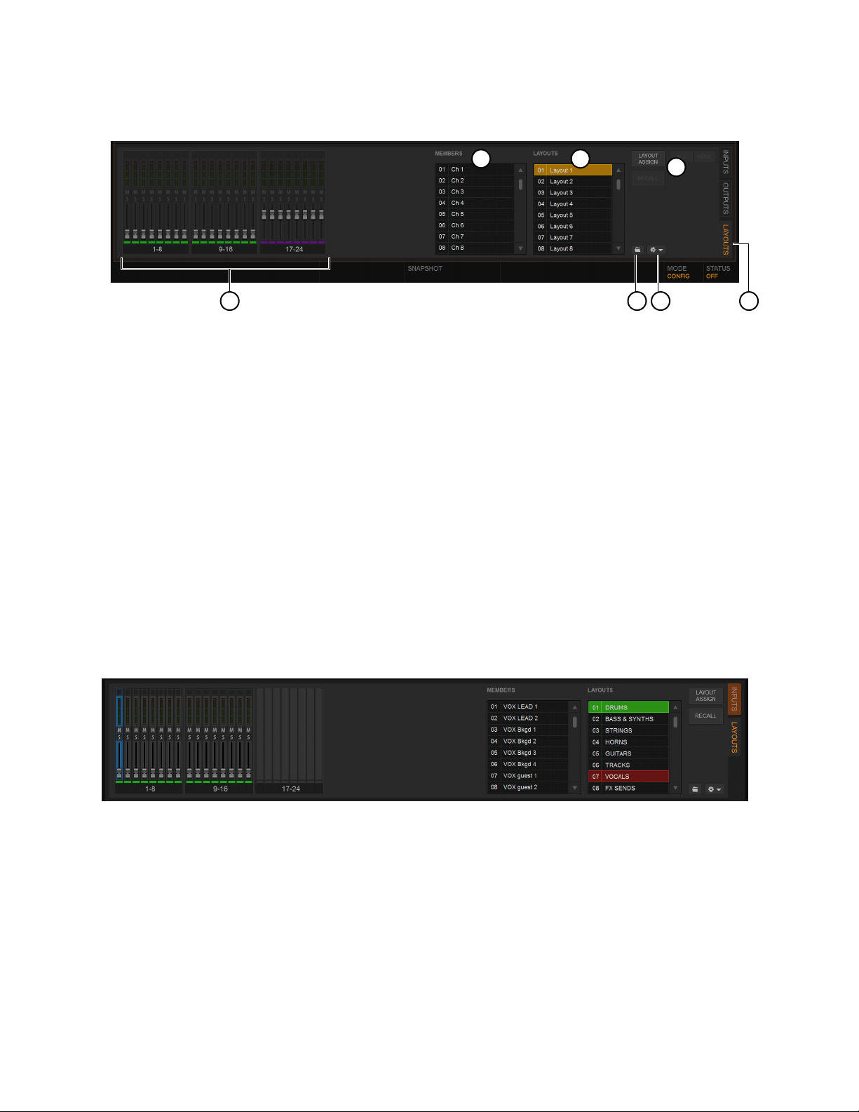
Banking Channels on the S6L Control Surface 95
Layouts View
The Layouts tab is available at the bottom of the Inputs, Outputs, and Snapshots views. Enabling the Layouts tab displays the fol-
lowing controls for assigning, recalling, and managing Layouts.
1 – Fader Strips
These strips correspond to all available fader strips on the control surface (32 on S6L-32D control surfaces, 24 on S6L-24D, or 16
on S6L-16C).
2 – Members
This scrollable display lists all channels assigned to the currently loaded Layout, or those assigned to the Layout currently targeted
in the Layouts list.
3 – Layouts List
This scrollable display lists the default Layout and all 23 available Layouts. To recall a Layout, click to select it (it lights red, in-
dicating it is targeted), then click the
Recall button. Channels assigned to the Layout appear in the Members list.
To rename a Layout:
Double-click its name in the Layouts List.
Similar to the Snapshots list, the Layouts list shows the currently loaded Layout in green. Selecting a different Layout in the list tar-
gets that Layout (it turns red) and its members appear in the Members list.
4 – Layout Assign and Recall
These switches enable Layout Assign mode and Recall the currently targeted Layout, respectively.
5 – Layouts Presets
This icon lets you create, preview, and load User Layout Presets.
Layouts tab
Layouts tab showing the current Layout (01 DRUMS) and a targeted Layout (07 VOCALS)
2 3
4
5 61 7
Banking Channels on the S6L Control Surface 96
6 – Layouts Options (Gear Menu)
This menu provides commands to manage Layouts, including Assign to Soft Key, Replace with Layout From, Auto Assign all
Soft Keys, Clear all Soft Keys, Clear, and Reset to Default.
7 – Layouts Tab
Selecting this tab displays Layouts view across the bottom of the external screen.
Layouts, Snapshots and Show Files
The following sections describe how Layouts are managed within Show files and snapshots.
Using Layouts in Snapshots
You can store and recall one User Layout per snapshot, providing up to 999 User Layouts per Show file. As with other snapshot
data types, the current User Layout and the associated parameters (mute, solo, etc.) are stored whenever you store a snapshot. How-
ever, because Layout 1 is associated with the current snapshot, updating that Layout is not automatically saved into the snapshot.
Be sure to store the associated snapshot after creating or editing the desired Layout.
Recalling a Snapshot with the
LAYT Data Type button scoped recalls the User Layout stored in the snapshot (see
Recalling Snap-
shots for more information).
The single Layout that is stored in a Show file created in an earlier version of VENUE software, and/or snapshot is always assigned
to MLM Soft Key 1. In addition:
• Any Layout currently stored in a Show file remains stored in the file as Layout 1.
• Any Layout currently stored in a snapshot remains stored in the snapshot as Layout 1.
• Storing a snapshot stores Layout 1.
• Recalling a snapshot with
LAYT scoped updates Layout 1, but does not force a Recall of Layout 1.
• While in any Fader Banking mode other than Layouts, when a snapshot is recalled with LAYT scoped the current Fader Bank-
ing mode is maintained. If you then enter Layouts Fader Banking Mode, faders will update to the Layout in the currently
loaded snapshot (Layout 1).
• Additional Layouts that are stored to Soft Keys are stored in the currently loaded Show file (not the Presets folder).
• Soft Key Assignments are stored in the Show file (not the Presets folder).
Using Mains in a User Layout
When you assign Mains L-R + C/Mono to a User Layout, a single fader for all three Mains buses is assigned to the Layout regard-
less of the Mains buses’ linked/unlinked state. When Mains are linked, adjusting the fader in the User Layout controls levels for
the linked Mains buses. See Using Mains in a User Layout for more information.
Commands in the Layouts Options (Gear menu)
Command Function
Assign to Soft Key
Assign the currently targeted Layout to any of the 24 avail-
able Layouts Soft Keys
Replace with Layout From
Replaces the currently targeted Layout with channel
assignments from the selected Layout
Auto Assign all Soft Keys
Assigns all Layouts 1–24 to corresponding Layouts Soft
Keys 1–24
Clear all Soft Keys Clears all Layout assignments from Soft Keys
Clear
Clears all channels assigned to the currently targeted Lay-
out
Reset to Default Resets Layout 1 to its default assignments

Banking Channels on the S6L Control Surface 97
Bank Safing Channels
Bank Safe lets you temporarily “lock” the location of key channels (such as a lead vocal or the Mains) on an S6L control surface
channel strip. This lets you maintain immediate access to these key channels while working with channels on a different layer.
When a channel is removed from Bank Safe, the channel that would normally appear in that fader location on the currently selected
bank automatically re-appears.
You can Bank Safe channels using the Channel Safe switches, the Channel Knob Module (CKM) in Channel Control mode, or the
Channel Menu. To Bank Safe channels using the Channel Safe switches, you must first enable Bank Safe mode.
Bank Safing Using the Channel Safe Switches/Button
The Channel Safe switch on the S6L control surface and the Channel Safe button on the external software screen toggle Bank Safe
for that channel when Bank Safe mode is enabled. Bank Safe Mode is enabled globally for input and output channels on the Options
> Interaction page of the external screen.
To enable Bank Safe for the Channel Safe switches:
1 On the external screen, go to the Options > Interaction page.
2 In the Channel Safe Switches Inputs and Outputs sections, select Bank Safes as de-
sired.
To Bank Safe channels using the Channel Safe switches:
1 Make sure you have enabled Bank Safe for the Channel Safe switches.
2 On the S6L control surface, do the following:
• Bank the desired channel to the faders.
• Press
Safe for the channel you want Bank Safe.
3 On the external screen, do the following:
• Go to the Inputs or Outputs page, and navigate to the desired channel using the provided tabs and buttons.
• Select the Channel Safe switch for the desired channel, located at the top of each fader strip.
Bank Safe status for the channel is indicated as follows:
• On the control surface channel strip, the
B LED lights red.
• In the Input section of the MTS and CTM Channel view for the channel, B lights red.
• On the external screen the Safe button flashes green and shows the letter B (A appears if the switch is acting as an Automation
Safe, and S appears if it is acting as a Solo Safe).
You can create an event that lets you cycle through the various Channel Safe switch
modes, suspend or disable Bank Safe (Disable Bank Switch). See
Creating Events.
S6L Channel Safe switch engaged
Indications that a channel is Bank Safed on the channel strip (left) the MTS/CTM Channel view (center) and on the external screen (right)
Channel Safe Switch options in the
Options > Interaction page
Menu Safe
Select
Solo
Y
X
Mute
AS B
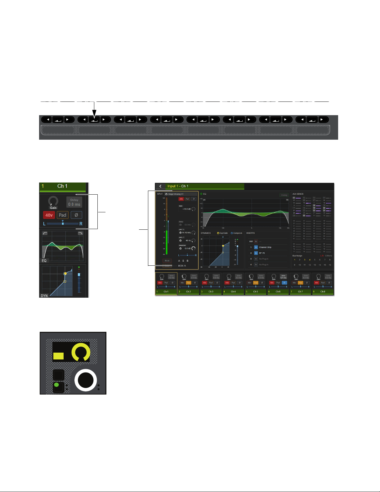
Banking Channels on the S6L Control Surface 98
Bank Safing Using the Channel Knob Module (CKM)
You can Bank Safe a channel using the CKM in Channel Control mode. You can Bank Safe a channel using the CKM when a dif-
ferent Safe mode (such as Automation and/or Solo Safe) is enabled for the Channel Safe switches.
To Bank Safe a channel using the CKM:
1 Bank the desired channel to the faders.
2 Press the Select switch for the channel you want to Bank Safe so it lights, then press the INPUT Channel Control Function
switch so it lights.
– or –
• Touch the channel’s Input touch zone on the associated Channel Touch Module (CTM). Input parameters are assigned to the as-
sociated CKM.
3 Locate the Bank Safe encoder, indicated by Bank Sf on the encoder display, and press the encoder.
The encoder In switch lights green, and the channel is Bank Safed.
CKM Channel Control Function Switches
Input touch zone on the CTM in Meters view (left) and in Channel view (right)
Bank Safe parameter on a CKM encoder
MIXMIXMIXPLUG-INSDYNAMICSEQINPUTCHANNEL
In
Sel
In
Sel
In
Sel
In
Sel
In
Sel
In
Sel
In
Sel
In
Sel
In
Sel
Bank Sf
ON

Banking Channels on the S6L Control Surface 99
Bank Safing Using the Channel Menu
You can Bank Safe a channel using the Channel Menu when a different Safe mode (such as Automation and/or Solo Safe) is en-
abled for the Channel Safe switches.
To Bank Safe a channel using the Channel Menu:
1 Bank the desired channel to the faders.
2 Press the Menu switch for the channel you want to Bank Safe until Safe Mode appears in the channel display. The Safe modes
enabled by the Left and Right Channel Menu switches are shown below Safe Mode.
3 Press the Right Channel Menu Switch so it lights to Bank Safe the channel. The B LED lights red.
Special Cases Affecting Bank Safe
Reordering/Moving Channels
Bank Safed channels shuffle accordingly when any operation is performed that results in a re-ordering of input channels, including
the following:
• Inserting or Removing a Blank Strip
• Moving a strip
• Splitting a stereo strip(s)
• Opening a Show file that was saved on a VENUE system that used a different control surface layout than S6L.
Make Stereo
The Bank Safe status of the left channel is applied to the newly created stereo channel.
Split Stereo
The Bank Safe status of the stereo channel is applied to only to the left channel of the former pair.
Right Channel Menu switch engaged
Menu Safe
Mute
AS B
Ch 1:Stage1-01
Source
Auto/Bank
Safe Mode
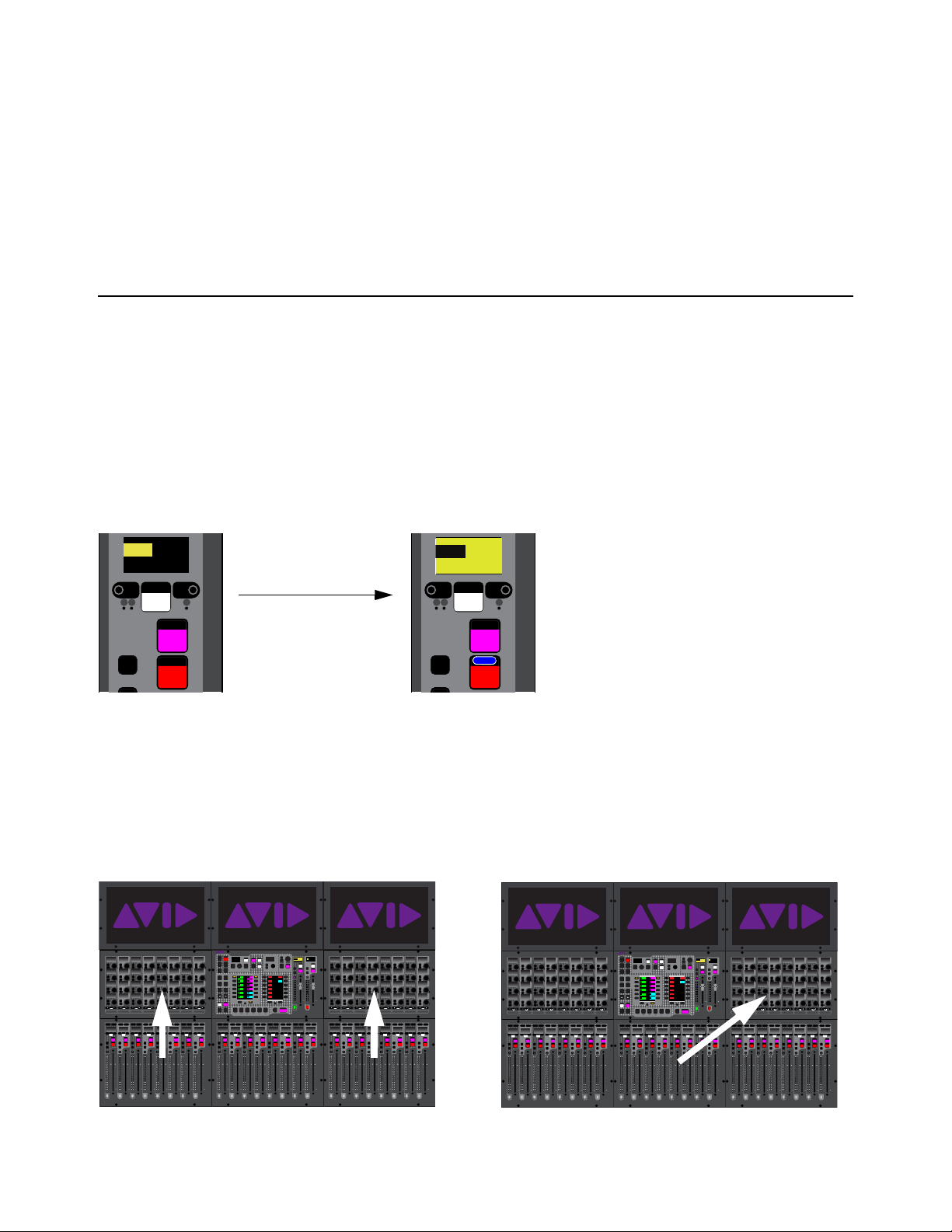
Selecting and Attentioning Channels 100
Selecting and Attentioning Channels
On the S6L system, there are two ways to target channels for processing, assigning, and other channel functions: selecting and at-
tentioning channels. Selecting a channel locally selects that channel, and targets it to the associated Channel Knob Module (CKM).
Attentioning channels targets channels to the external VENUE software screen and the Master Touch Screen (MTS, if present).
Selecting Channels
Selecting a channel lets you adjust the channel’s parameters using the associated CKM. You can select channels using fader strip
Select switches, using the associated Channel Touch Module (CTM) if available, or by enabling the Select Follows Solo setting.
Selecting a Channel Using the Select Switch
To select a channel using the channel strip Select switch:
1 Bank to the desired channels.
2 Press Select on the corresponding channel strip so it lights. The background of the display also lights yellow to indicate that the
channel is selected.
Depending on the fader bank from which you selected the channel, you can adjust the selected channel’s parameters from an as-
sociated CKM, as follows:
• On all models of control surface, selecting a channel on a fader bank below a CKM enables Channel Control mode on that
CKM, at shown in the following figure on the left (S6L-24D shown).
• On S6L-32D/24D, selecting a channel on the fader bank below the Master Live Module (MLM) enables Channel Control
mode on the CKM to the right of the MLM, as shown in the following figure on the right (S6L-24D shown).
• On S6L-24C or S6L-16C, selecting any channel enables Channel Control mode on the one CKM (above faders 1–8)
An unselected channel (left) and a selected channel (right
Selecting a channel below a CKM (left) and below the MLM (right) on an S6L-24D
Select
Solo
X
Mute
AS B
CH 1
Ch 1
0.0 dB
Select
Solo
X
Mute
AS B
CH 1
Ch 1
0.0 dB
0.0 dB
CH 1
Ch 1
Select
Solo
X
Mute
AS B
CH 1
Ch 1
0.0 dB
60
40
30
20
10
5
0
6
12
60
40
30
20
10
5
0
6
12
Select
Solo
Select
Solo
Select
Solo
Select
Solo
Select
Solo
Select
Solo
Select
Solo
Select
Solo
BAS
Menu Safe
Mute
Y
X
Y
X
Y
X
Y
X
Y
X
Y
X
Y
X
Y
X
BAS
Menu Safe
Mute
BAS
Menu Safe
Mute
BAS
Menu Safe
Mute
BAS
Menu Safe
Mute
BAS
Menu Safe
Mute
BAS
Menu Safe
Mute
BAS
Menu Safe
Mute
60
40
30
20
10
5
0
6
12
60
40
30
20
10
5
0
6
12
60
40
30
20
10
5
0
6
12
60
40
30
20
10
5
0
6
12
60
40
30
20
10
5
0
6
12
60
40
30
20
10
5
0
6
12
60
30
21
15
9
3
0
3
9
15
60
30
21
15
9
3
0
3
9
15
60
30
21
15
9
3
0
3
9
15
60
30
21
15
9
3
0
3
9
15
60
30
21
15
9
3
0
3
9
15
60
30
21
15
9
3
0
3
9
15
60
30
21
15
9
3
0
3
9
15
60
30
21
15
9
3
0
3
9
15
Nom
60
40
30
20
10
5
0
6
12
60
40
30
20
10
5
0
6
12
Select
Solo
Select
Solo
Select
Solo
Select
Solo
Select
Solo
Select
Solo
Select
Solo
Select
Solo
BAS
Menu Safe
Mute
Y
X
Y
X
Y
X
Y
X
Y
X
Y
X
Y
X
Y
X
BAS
Menu Safe
Mute
BAS
Menu Safe
Mute
BAS
Menu Safe
Mute
BAS
Menu Safe
Mute
BAS
Menu Safe
Mute
BAS
Menu Safe
Mute
BAS
Menu Safe
Mute
60
40
30
20
10
5
0
6
12
60
40
30
20
10
5
0
6
12
60
40
30
20
10
5
0
6
12
60
40
30
20
10
5
0
6
12
60
40
30
20
10
5
0
6
12
60
40
30
20
10
5
0
6
12
60
30
21
15
9
3
0
3
9
15
60
30
21
15
9
3
0
3
9
15
60
30
21
15
9
3
0
3
9
15
60
30
21
15
9
3
0
3
9
15
60
30
21
15
9
3
0
3
9
15
60
30
21
15
9
3
0
3
9
15
60
30
21
15
9
3
0
3
9
15
60
30
21
15
9
3
0
3
9
15
Nom
MIXMIXMIXPLUG-INSDYNAMICSEQINPUTCHANNEL
In
Sel
In
Sel
In
Sel
In
Sel
In
Sel
In
Sel
In
Sel
In
Sel
In
Sel
In
Sel
In
Sel
In
Sel
In
Sel
In
Sel
In
Sel
In
Sel
In
Sel
In
Sel
In
Sel
In
Sel
In
Sel
In
Sel
In
Sel
In
Sel
In
Sel
In
Sel
In
Sel
In
Sel
In
Sel
In
Sel
In
Sel
In
Sel
MIXMIXMIXPLUG-INSDYNAMICSEQINPUTCHANNEL
In
Sel
In
Sel
In
Sel
In
Sel
In
Sel
In
Sel
In
Sel
In
Sel
In
Sel
In
Sel
In
Sel
In
Sel
In
Sel
In
Sel
In
Sel
In
Sel
In
Sel
In
Sel
In
Sel
In
Sel
In
Sel
In
Sel
In
Sel
In
Sel
In
Sel
In
Sel
In
Sel
In
Sel
In
Sel
In
Sel
In
Sel
In
Sel
VENUE | S6L
Solo Solo
Home
Config
VCAs
Outputs
Layouts
Inputs
Flip
Recall
Trans
F1 F2 F3 F4 F5
NEXT
PREV
Store
Y
X
Y
X
AFL
Dim
In
Sel
SNAPSHOTS
Talk
Back
Multi
Select
Encoder
Assign
Select
Clear
Tap
Tempo
Multi
Assgn
Default Fine
OK Cancel
Over
Write
Mix to
Mon
Solo
Clear
60
40
30
20
10
5
0
6
12
60
40
30
20
10
5
0
6
12
8All
Preview
ASSIGNABLE ENCODER MONITORING
Push A/BHold SIP
SHIFT
ALT
CTRL
ESC
Mute Mute
A
B
Nom
30
21
15
9
3
0
3
9
15
30
21
15
9
3
0
3
9
15
Inputs/Outputs
Next
Global Controls
0.0 dB
L
Left
0.0 dB
Kick
Mute Group 1
Mute Group
Function KeysMute Group 2
Mute Group 3
Mute Group 4
Mute Group 5
Mute Group 6
M1
M2
M3
M4
M5
M6
0
01/011
reset all inputs
0.0 dB
CH 1
Kick
Ch 1-16
1-16
Aux 1-8
1-8
Aux 9-16
Aux 17-24
Aux 25-32
25-32
VCA 1-8
1-8
VCA 9-16
9-16
Ch 17-32
17-32 9-16
Ch 33-48
33-48 17-24
Ch 49-64
49-64
Ch 65-80
65-80
Ch 81-96
81-96
60
40
30
20
10
5
0
6
12
60
40
30
20
10
5
0
6
12
Select
Solo
Select
Solo
Select
Solo
Select
Solo
Select
Solo
Select
Solo
Select
Solo
Select
Solo
BAS
Menu Safe
Mute
Y
X
Y
X
Y
X
Y
X
Y
X
Y
X
Y
X
Y
X
BAS
Menu Safe
Mute
BAS
Menu Safe
Mute
BAS
Menu Safe
Mute
BAS
Menu Safe
Mute
BAS
Menu Safe
Mute
BAS
Menu Safe
Mute
BAS
Menu Safe
Mute
60
40
30
20
10
5
0
6
12
60
40
30
20
10
5
0
6
12
60
40
30
20
10
5
0
6
12
60
40
30
20
10
5
0
6
12
60
40
30
20
10
5
0
6
12
60
40
30
20
10
5
0
6
12
60
30
21
15
9
3
0
3
9
15
60
30
21
15
9
3
0
3
9
15
60
30
21
15
9
3
0
3
9
15
60
30
21
15
9
3
0
3
9
15
60
30
21
15
9
3
0
3
9
15
60
30
21
15
9
3
0
3
9
15
60
30
21
15
9
3
0
3
9
15
60
30
21
15
9
3
0
3
9
15
Nom
60
40
30
20
10
5
0
6
12
60
40
30
20
10
5
0
6
12
Select
Solo
Select
Solo
Select
Solo
Select
Solo
Select
Solo
Select
Solo
Select
Solo
Select
Solo
BAS
Menu Safe
Mute
Y
X
Y
X
Y
X
Y
X
Y
X
Y
X
Y
X
Y
X
BAS
Menu Safe
Mute
BAS
Menu Safe
Mute
BAS
Menu Safe
Mute
BAS
Menu Safe
Mute
BAS
Menu Safe
Mute
BAS
Menu Safe
Mute
BAS
Menu Safe
Mute
60
40
30
20
10
5
0
6
12
60
40
30
20
10
5
0
6
12
60
40
30
20
10
5
0
6
12
60
40
30
20
10
5
0
6
12
60
40
30
20
10
5
0
6
12
60
40
30
20
10
5
0
6
12
60
30
21
15
9
3
0
3
9
15
60
30
21
15
9
3
0
3
9
15
60
30
21
15
9
3
0
3
9
15
60
30
21
15
9
3
0
3
9
15
60
30
21
15
9
3
0
3
9
15
60
30
21
15
9
3
0
3
9
15
60
30
21
15
9
3
0
3
9
15
60
30
21
15
9
3
0
3
9
15
Nom
MIXMIXMIXPLUG-INSDYNAMICSEQINPUTCHANNEL
In
Sel
In
Sel
In
Sel
In
Sel
In
Sel
In
Sel
In
Sel
In
Sel
In
Sel
In
Sel
In
Sel
In
Sel
In
Sel
In
Sel
In
Sel
In
Sel
In
Sel
In
Sel
In
Sel
In
Sel
In
Sel
In
Sel
In
Sel
In
Sel
In
Sel
In
Sel
In
Sel
In
Sel
In
Sel
In
Sel
In
Sel
In
Sel
MIXMIXMIXPLUG-INSDYNAMICSEQINPUTCHANNEL
In
Sel
In
Sel
In
Sel
In
Sel
In
Sel
In
Sel
In
Sel
In
Sel
In
Sel
In
Sel
In
Sel
In
Sel
In
Sel
In
Sel
In
Sel
In
Sel
In
Sel
In
Sel
In
Sel
In
Sel
In
Sel
In
Sel
In
Sel
In
Sel
In
Sel
In
Sel
In
Sel
In
Sel
In
Sel
In
Sel
In
Sel
In
Sel
VENUE | S6L
Solo Solo
Home
Config
VCAs
Outputs
Layouts
Inputs
Flip
Recall
Trans
F1 F2 F3 F4 F5
NEXT
PREV
Store
Y
X
Y
X
AFL
Dim
In
Sel
SNAPSHOTS
Talk
Back
Multi
Select
Encoder
Assign
Select
Clear
Tap
Tempo
Multi
Assgn
Default Fine
OK Cancel
Over
Write
Mix to
Mon
Solo
Clear
60
40
30
20
10
5
0
6
12
60
40
30
20
10
5
0
6
12
8All
Preview
ASSIGNABLE ENCODER MONITORING
Push A/BHold SIP
SHIFT
ALT
CTRL
ESC
Mute Mute
A
B
Nom
30
21
15
9
3
0
3
9
15
30
21
15
9
3
0
3
9
15
Inputs/Outputs
Next
Global Controls
0.0 dB
L
Left
0.0 dB
Kick
Mute Group 1
Mute Group
Function KeysMute Group 2
Mute Group 3
Mute Group 4
Mute Group 5
Mute Group 6
M1
M2
M3
M4
M5
M6
0
01/011
reset all inputs
0.0 dB
CH 1
Kick
Ch 1-16
1-16
Aux 1-8
1-8
Aux 9-16
Aux 17-24
Aux 25-32
25-32
VCA 1-8
1-8
VCA 9-16
9-16
Ch 17-32
17-32 9-16
Ch 33-48
33-48 17-24
Ch 49-64
49-64
Ch 65-80
65-80
Ch 81-96
81-96
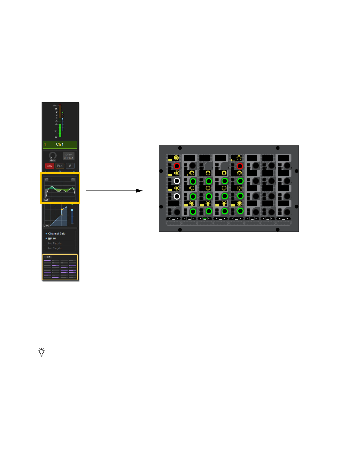
Selecting and Attentioning Channels 101
Selecting a Channel From Meters View
You can select channels from the Meters view or Channel view on the MTS and CTMs (if any).
To select a channel while in Meters view:
1 Bank the desired channel to any fader bank except the fader bank under the MLM.
2 In Meters view, do any of the following:
• Touch the Input, EQ, Dynamics, Plug-Ins, or Mix touch zone for the channel you want to select. That channel is selected, the
touch zone is bordered in orange, and the parameters associated with the active touch zone are spilled to the associated CKM
in Channel Control mode.
• Or touch the channel’s Meter touch zone.
The CTM (if any) switches to Channel view. The Channel Tile for the currently selected channel is bordered in orange, and the
parameters associated with the last active Channel Control function are spilled to the associated CKM in Channel Control mode.
To select a different channel in Channel view:
Touch a different Channel Tile at the bottom of the display. That channel is now selected, and the encoders on the CKM now tar-
get the selected channel.
Select Follows Solo
The setting Select Follows Solo is provided in the Channel Selection section of the Options > Interaction page. When enabled,
engaging Solo on any channel that is currently banked to the faders also selects that channel. Solo can be engaged from the CFM,
MTS, or external screen, but the channel must already be banked to the control surface to engage local Select.
Selecting the EQ touch zone spills EQ parameters in Channel Control mode to the associated CKM in Channel Control mode.
When using an S6L-24C control surface, an additional option becomes available in Options > Interaction. For more infor-
mation, see
Meters Follow Selection (S6L-24C Only).
15
MIXMIXMIXPLUG-INSDYNAMICSEQINPUTCHANNEL
In
Sel
In
Sel
In
Sel
In
Sel
In
Sel
In
Sel
In
Sel
In
Sel
In
Sel
In
Sel
In
Sel
In
Sel
In
Sel
In
Sel
In
Sel
In
Sel
In
Sel
In
Sel
In
Sel
In
Sel
In
Sel
In
Sel
In
Sel
In
Sel
In
Sel
In
Sel
In
Sel
In
Sel
In
Sel
In
Sel
In
Sel
In
Sel
IN IN IN IN
IN
IN
IN
IN
ON
ON
ON
ON
IN IN
IN IN
EQ In Analog
Hi Gain
Hi Freq
HM Freq
LM Freq
Lo Freq
Lo Q
1.00
200 Hz 1.00 kHz 5.00 kHz
10.00 kHz
0.0 dB
0.0 dB
0.0 dB
0.0 dB
1.00 1.00 1.00
LM Q
HM Q
Hi Q
HM Gain
LM Gain
Lo Gain
LPF
HPF
80 Hz
20.00 kHz
IN IN
IN IN
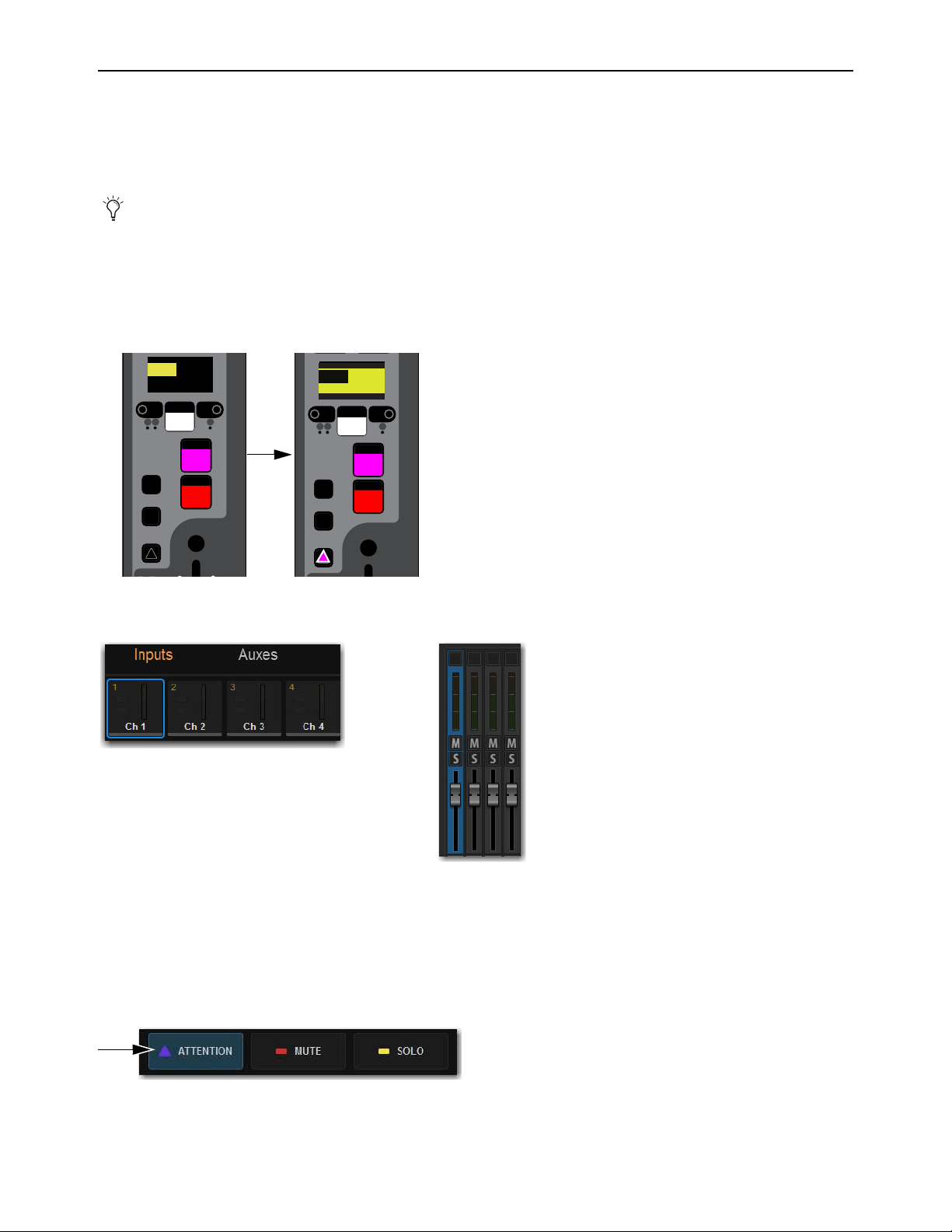
Selecting and Attentioning Channels 102
Attentioning Channels
You can attention a channel using the channel strip Attention switches, the Universe view, or from the fader strips on the external
screen. Attentioning a channel targets the channel to the Inputs or Outputs page of the external VENUE software screen, from
which you can adjust channel parameters independently of selected channels. The attentioned channel is also targeted to the MTS
Channel view (all systems except S6L-16C).
To attention a channel using the Attention switch:
1 Bank to the desired channels.
2 Press Attention on the corresponding channel strip so it lights. The channel display inverts (black text on a yellow background)
with black borders above and below, distinguishing it from indication of channel Select.
On the MTS/Universe view, the channel tile is bordered in blue. On the external screen the fader lights blue.
To attention a channel using the Universe view:
1 On the MTS or external screen (S6L-16C only) touch Universe to show the Universe view.
2 Touch the appropriate Channel Type button (Inputs, Auxes, Groups, Matrixes, VCAs, or Mains) to show the channel you want
to attention.
3 Touch the Attention Channel Tile Function button so it lights.
4 Touch the channel tile. The channel tile is bordered in blue to indicate the channel is attentioned.
By default, selecting a channel also attentions it. You can change this behavior to decouple Select and Attention by changing
the
Attention Follows Select preference in the Options > Interaction tab on the external screen.
An unselected and unattentioned channel (left) and an attentioned channel (right
Indications of attentioned channels in the MTS (left) and on the external screen (right)
An enabled Attention Channel Tile Function button
Select
Solo
Y
X
Mute
AS B
CH 1
Ch 1
0.0 dB
12
Select
Solo
Y
X
Mute
AS B
CH 1
Ch 1
0.0 dB
0.0 dB
CH 1
Ch 1
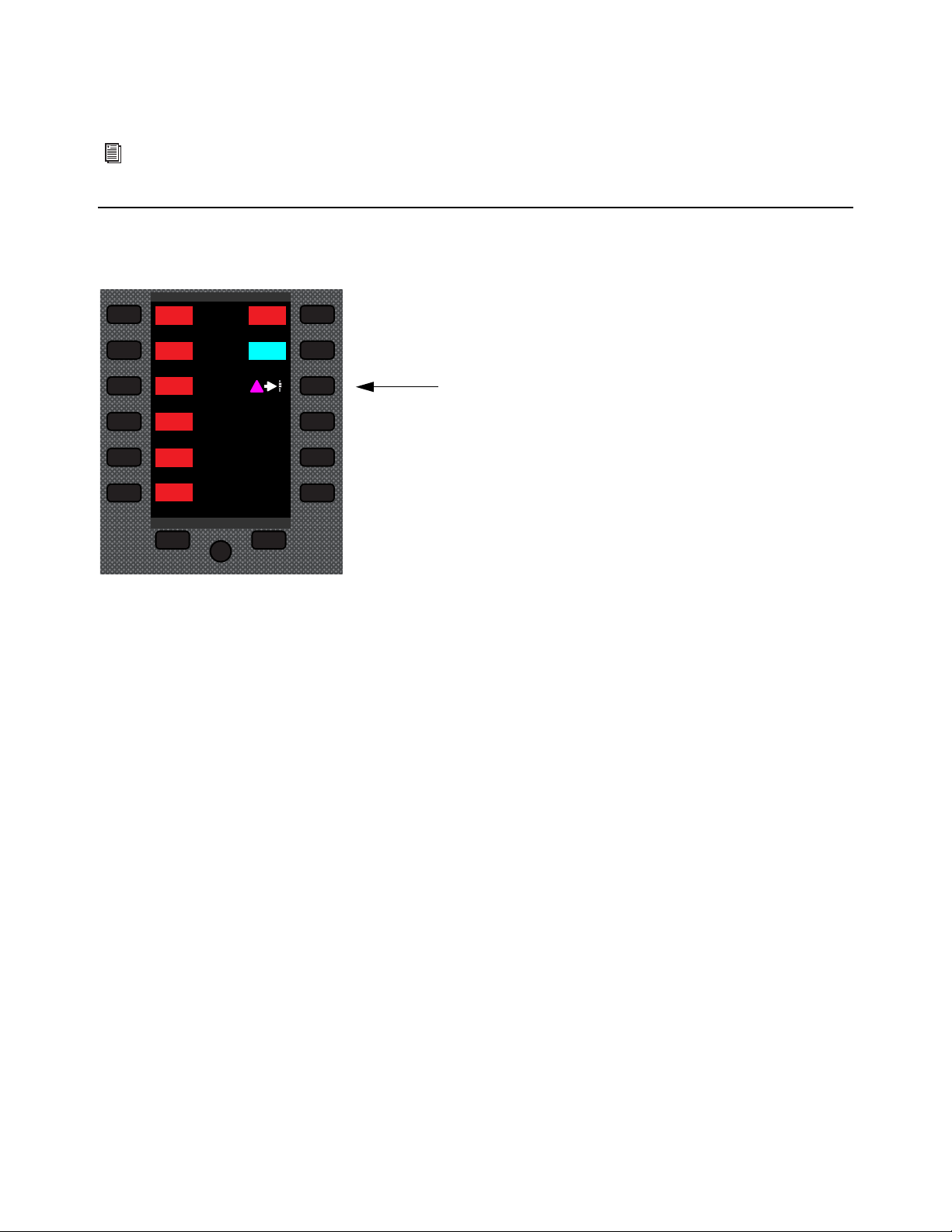
Selecting and Attentioning Channels 103
To view the attentioned channel in the MTS Channel view:
Touch Channel. The currently attentioned channel’s parameters are shown. When you attention another channel, its parameters
are shown in the Channel view.
Attention on Fader
Use the Attention on Fader soft key to quickly access parameters on the currently attentioned channel.
Pressing the soft key for Attention on Fader places the currently attentioned channel on the first fader of the CFM below the MLM,
and locally selects it. The Select switch on that strip flashes purple. The Attention on Fader will override any Bank Safed channel
on the strip (any Bank Safed channel will remain on that strip but is temporarily hidden by the Attention on Fader).
The CKM OLEDs display any previously displayed parameters (or Channel view if no parameters were previously displayed in At-
tention on Fader mode).
When the channel is unselected (by pressing its flashing
Select switch, selecting another channel in that bank of 8 faders or the
bank to its right (if present), pressing Select Clear, pressing the Attention on Fader soft key again, or closing Channel view on a
CTM), the Attention on Fader strip returns to its previous channel assignment. Changing fader banks will unselect faders on the
previous bank.
Flip mode and Sends on Faders mode remain available and do not cancel Attention Floating Fader mode.
For information on working with external screen controls, including attentioning channels, see
Adjusting Parameters on
the External Screen.
Attention Floating Fader
Global Controls
Mute Group 1
Mute Group
Function KeysMute Group 2
Mute Group 3
Mute Group 4
Mute Group 5
Mute Group 6
M1
M2
M3
M4
M5
M6
Attention on Fader

Selecting and Attentioning Channels 104
Selecting/Attentioning Multiple Channels (Multi-Select)
Multi-Select lets you select or attention multiple channels in order to apply an action to them in one step, such as adjusting multiple
channel’s High-Pass Filters, turning Aux sends on or off for multiple channels, or assigning multiple channels to a bus. You can
multi-select channels using
Select or Attention.
When you multi-select using Select, you can adjust parameters for all selected channels using the associated CKM. When you
multi-select using Attention, you can adjust parameters for all attentioned channels using the controls on the external screen.
Mutli-Selecting Using Select
Multi-selecting using Select is “local”–only channels on the same fader bank can be multi-selected using Select.
To multi-select channels using the Select switch:
1 Bank to the desired channels.
2 Do either of the following:
• Press and hold the Multi-Select switch at the top-left of the MLM, then press the Select switch on each channel you want
to include in the selection.
• Hold down the Select switch on the first channel, then press the Select switch on each channel you want to include in the
selection.
3 If you used Multi-Select, release the Multi-Select switch. The flashing Multi-Select switch flashes to indicate Multi–Select
mode is enabled.
4 Press a Channel Control Function switch to target those parameters to the associated CKM encoders.
5 Adjust a parameter on the CKM. The operation is applied to all selected channels.
6 To exit Multi-Select mode, do any of the following:
• Select an unselected channel on the same fader bank.
• Bank to a different set of channels.
Multi-Select switch
You can also use the Shift key on the keyboard to select multiple channels.
VENUE | S6L
Home Config
Recall
Store
Y
X
AFL
Dim
In
Sel
SNAPSHOTS
Talk
Back
Multi
Select
Multi
Assgn
Default Fine
OK Cancel
Over
Write
Mix to
Mon
Solo
Clear
Preview
ASSIGNABLE ENCODER MONITORING
Push A/BHold SIP
SHIFT
ALT
CTRL
ESC
A
B
0.0
001/011
reset all inputs
0.0
CH 1
S1Cu2
001 3
P:S1C1
N:S1C3
S1Cu3
S1Cu2
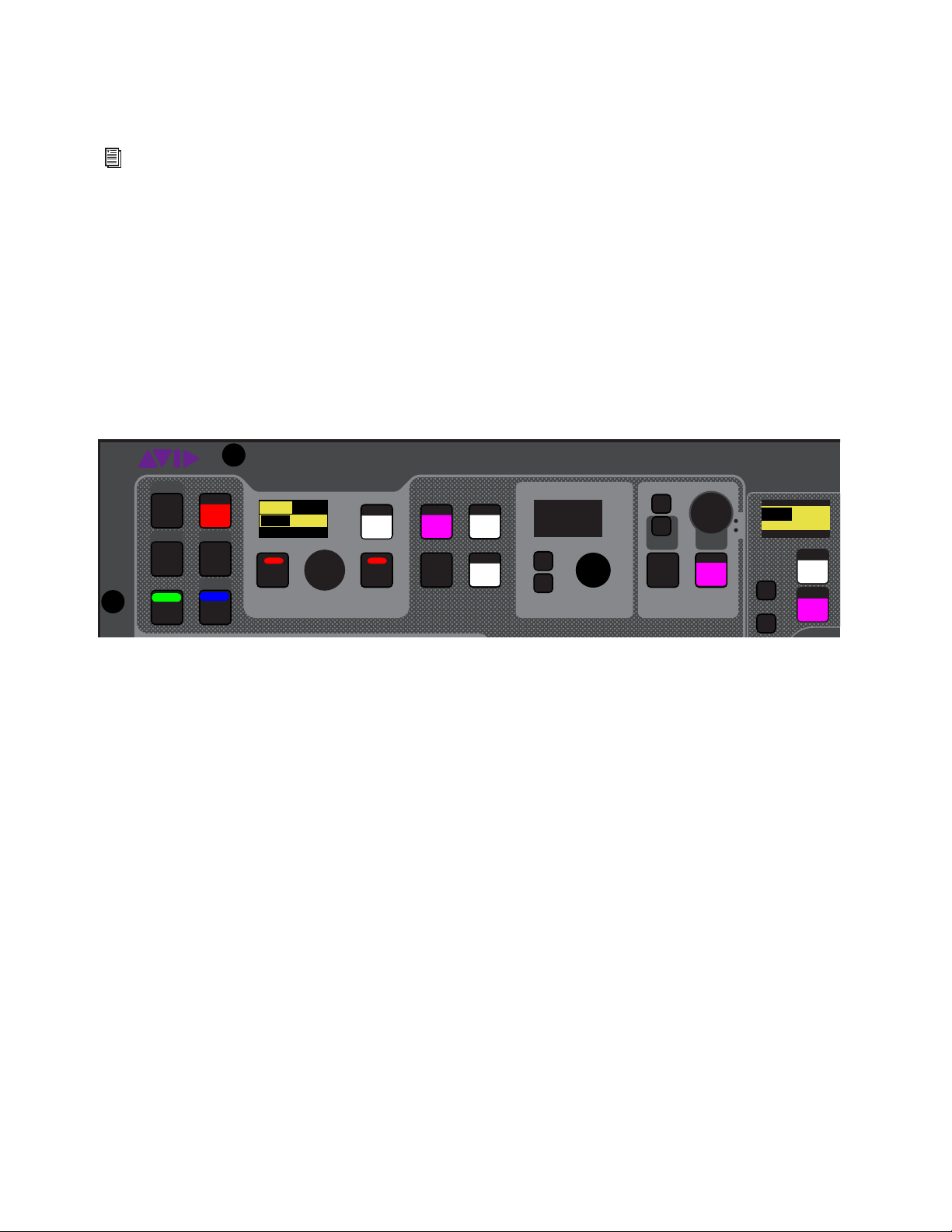
Selecting and Attentioning Channels 105
Mutli-Selecting Using Attention
Multi-selecting using Attention is “global”–any channels in the system regardless of its current banking status can be multi-se-
lected using Attention.
To multi-select channels using Attention switches:
Press and hold the Attention switch on the first channel you want to attention, then press Attention on each channel you want
to include.
To multi-select channels using Multi-Select:
1 Press and hold the Multi-Select switch at the top-left of the MLM.
2 Press the Attention switches for any channels you want to include in the selection.
3 If necessary, bank to other channels as desired, and press their Attention switches to add to the multi-selection.
4 When finished multi-selecting channels, release the Multi-Select switch. The flashing Multi-Select, OK and Cancel switches,
and the banner display at the lower left of the external screen flash to indicate Multi–Select mode is enabled.
5 To adjust parameters, do any of the following:
• If no channel is locally selected, adjust a parameter on the CKM in Channel Strip mode.
• Press the
Select switch to enable Channel Control mode on the associated CKM, then press a Channel Control function
switch to access the desired parameter(s).
Any adjustments are applied to all multi-selected channels.
6 To exit Multi-Select mode, do any of the following:
• Attention an un-attentioned channel.
• Press
Cancel.
• Press Multi-Select.
For information on working with external screen controls, including attentioning channels, see
Attentioning Channels
from the External Screen.
Flashing OK and Cancel switches
VENUE | S6L
Solo
Home
Config
Recall
Store
Y
X
AFL
Dim
In
Sel
SNAPSHOTS
Talk
Back
Multi
Select
Multi
Assgn
Default Fine
OK Cancel
Over
Write
Mix to
Mon
Solo
Clear
Preview
ASSIGNABLE ENCODER MONITORING
Push A/BHold SIP
SHIFT
ALT
CTRL
ESC
Mute
A
B
0.0 dB
Kick
001/011
reset all inputs
0.0 dB
CH 1
Kick
S1Cu2
001 3
P:S1C1
N:S1C3
S1Cu3
S1Cu2

Adjusting Channel Parameters 106
Adjusting Channel Parameters
This chapter describes the following:
•
Assigning Channels to Outputs
• Adjusting Input Parameters on the Control Surface
• Adjusting EQ on the Control Surface
• Adjusting Dynamics on the Control Surface
• Adjusting Plug-Ins on the Control Surface
• Using the CHANNEL Function
• Flipping Parameters to Faders (Flip to Faders Mode)
• Encoder Assign Mode
Configuring and Patching Channels
Before adjusting channels, make sure you have configured your Mains and Mix Buses, patched hardware I/O to input and output
channels, and configured channels as desired (such as naming channels and making stereo channels). See the following for more
information:
Configure Mains and Mix Buses (Aux and Groups) on the System > Options page. See
Configuring Mains and Mix Buses.
Patch hardware I/O to input and output channels using the VENUE Patchbay. See Patching Input Sources to Input Channels
for more information.
Name channels, combine two mono channels into one stereo channel (make stereo), reorder input channels, and insert blank
channel strips using the Inputs and Outputs pages of the external screen. See
Configuring Channels on the External Screen for
more information.
You can also adjust many channel parameters using the external VENUE software screen. See
Adjusting Parameters on
the External Screen for more information.
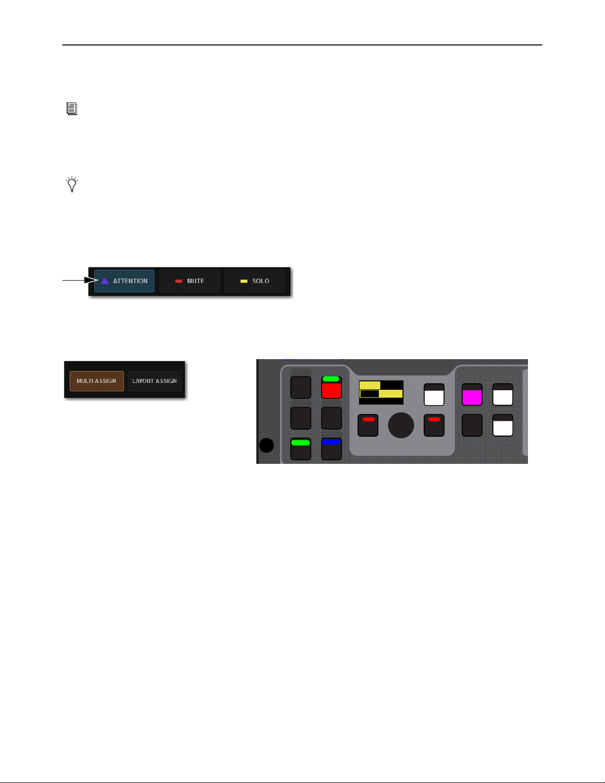
Adjusting Channel Parameters 107
Assigning Channels to Outputs
You can assign channels to the Mains, Auxes, Groups and VCAs using Multi-Assign. You can assign channels to the Mains and
Groups using the CKMs in Channel Control mode.
Assigning Channels Using Multi-Assign
Multi-Assign lets you assign multiple channels to a bus or VCA at once. Assigning channels using the MTS is the quickest and eas-
iest way to assign channels.
To assign channels using Multi-Assign:
1 On the MTS, touch the Channel Type button for the output you want to target for the multi-assign (Auxes, Groups, VCAs, or
Mains).
2 Touch Attention.
3 Touch the channel tile for the output channel you want to target for the multi-assign so the channel tile is bordered in blue.
4 Touch Multi-Assign on the CTM, or press the Multi-Assign switch on the control surface MLM so they are lit.
5 On the MTS, touch Inputs, and then touch the channel tiles for the channels you want to assign so the channel tiles are bordered
in orange.
– or –
• Bank the desired input channels to the faders and press their
Attention switches.
6 To confirm the assignment and exit Multi-Assign mode, press the OK switch
7 To cancel the assignment, press the Cancel switch, or press the Esc key on your keyboard.
For information on assigning input sources to Matrix Mixers, see
Assigning Input Sources to Matrix Mixers.
You can also multi-assign to
Mute Groups.
An enabled Attention Channel Tile Function button
Enabled Multi-Assign button on the MTS (left) and on the MLM (right)
VENUE | S6L
Home Config
Recall
Store
SNAPSHOTS
Talk
Back
Multi
Select
Multi
Assgn
Default Fine
OK Cancel
Over
Write
Preview
A
SHIFT
ALT
CTRL
ESC
001/011
reset all inputs
S1Cu2
001 3
P:S1C1
N:S1C3
S1Cu3
S1Cu2
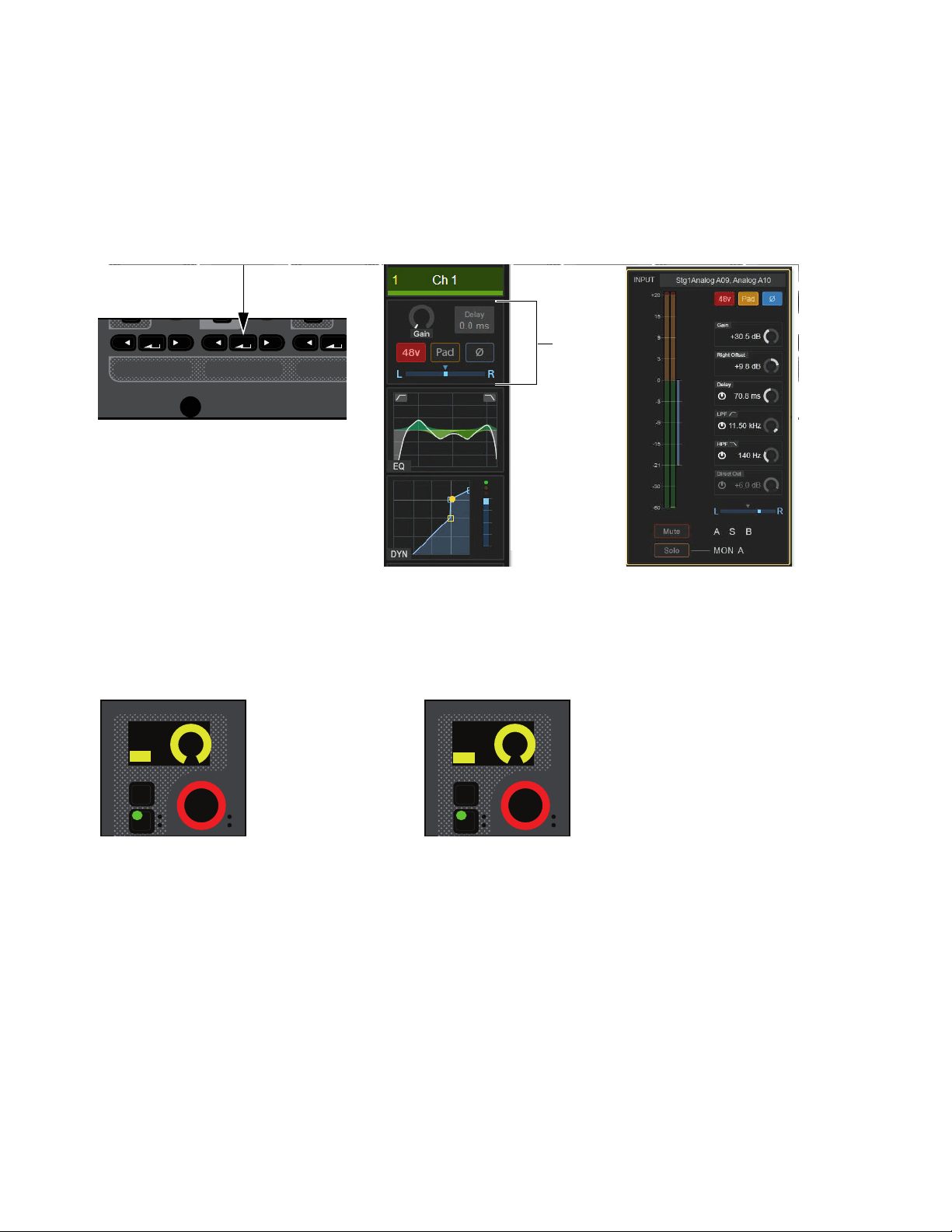
Adjusting Channel Parameters 108
Assigning Channels to the Mains
You can assign input channels to the Mains using the CKM encoders in Channel Control mode and on the external screen:
To assign input channels, Aux outputs, and Group outputs to Mains in Channel Control mode:
1 Select one or more channels you want to assign to the Mains buses.
2 On the associated CKM, press the INPUT Channel Control Function switch
– or –
• Touch the Input touch zone for the desired channel on the associated CTM in Meters or Channel view.
3 Do any of the following:
• To assign the channel(s) to the Mains Left and Right, press the encoder under the display showing L-R Assign.
• To assign the channel(s) to the Mains Center/Mono, press the encoder under the display showing C-M Assign.
The encoder In switch lights, the virtual encoder surround on the display fills, and the encoder turns red.
Input Channel Control Function switch (left), Input touch zone in Meters view (center), Input touch zone in Channel view (right)
Encoder and display showing a channel assigned to Mains L-R (left) and C/Mono (right)
MIXMIXMIXPLUG-INSDYNAMICSEQINPUTCHANNEL
In
Sel
In
Sel
In
Sel
In
Sel
In
Sel
In
Sel
In
Sel
In
Sel
In
Sel
L - R Asn
ON
In
Sel
C-M Asn
ON
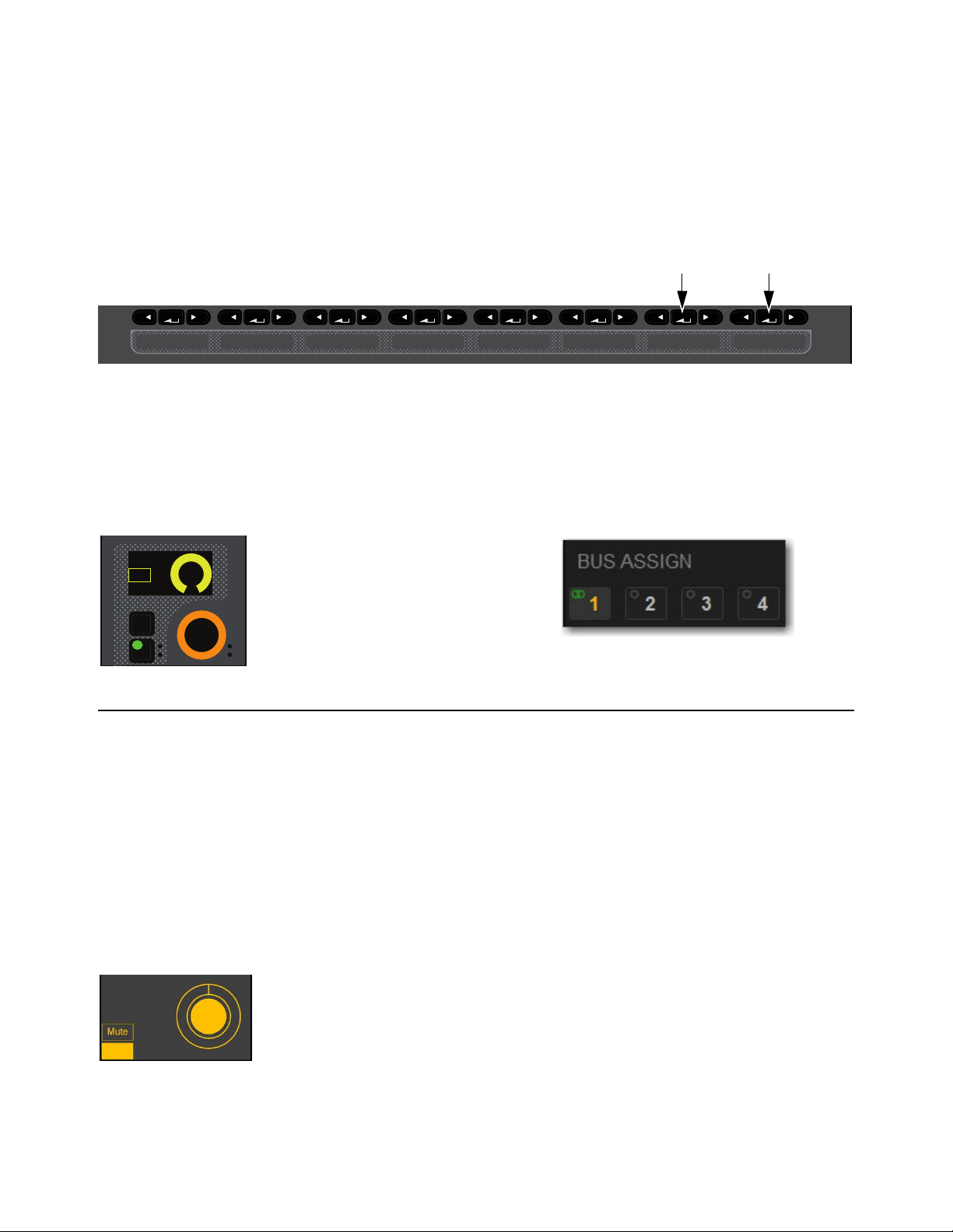
Adjusting Channel Parameters 109
Assigning Input Channels to Groups
You can assign input channels to Groups using the CKM. The number of Group buses available, and which Mix Channel Control
function switch lets you access them, depends on the overall Mix Bus configuration. To change the Mix Bus configuration, see
Configuring Mix Buses.
To assign an input channel to a Group in Channel Control mode:
1 Select one or more channels.
2 On the associated CKM, press Mix Channel Control Function switch 2 or 3, depending on the overall Mix Bus configuration.
Group assigns are spilled to the encoders.
3 Press the orange encoder under the display showing the Group to which you want to assign the channel(s). The following ele-
ments indicate that the channel is assigned:
• The encoder
In switch lights.
• In the encoder display, On is shown and the encoder fills in.
• On-screen, the corresponding bus indicators are lit in the Bus Assign sections of the MTS and CTM Channel views, and on
the Inputs page of the external screen.
Assign VCAs and Mute Groups from Channel Control Encoders
You can assign input channels to Mute Groups and VCAs using the CKM encoders in Channel Control mode.
To assign input channels to Mute Groups and VCAs in Channel Control mode:
1 Select one or more channels you want to assign to a VCA or Mute Group.
2 On the associated CKM, press the INPUT Channel Control Function switch.
Or, touch the Input touch zone for the desired channel on the associated CTM in Meters or Channel view.
3 To assign the channel(s) to a Mute Group, rotate the encoder under the display showing MUTE Asn.
4 To assign the channel(s) to a VCA, rotate the encoder under the display showing VCA Asn.
5 When the desired VCA or Mute Group is displayed in the OLED, press the encoder or press the IN switch next to the encoder.
The SEL switch indicates Mute status of the currently selected VCA or MUTE Group. Pressing SEL toggles Mute of the selected
VCA or MUTE group.
Mix Channel Control Function Switches
Encoder and display showing a channel assigned to Group 1 (left) and on-screen for the selected/attentioned channel (right)
CKM OLED showing a channel assigned to the Mute Group “All Band”
MIXMIXMIXPLUG-INSDYNAMICSEQINPUTCHANNEL
In
Sel
Grp 1
On
IN
IN
VCA-Asn
VCA 1
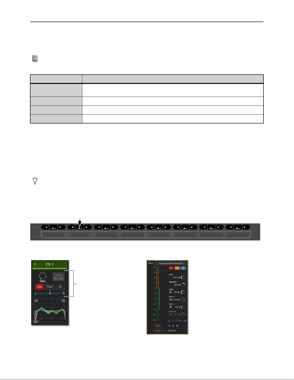
Adjusting Channel Parameters 110
Adjusting Input Parameters
on the Control Surface
This section describes how to adjust top-of-channel parameters, which are the parameters you access when you press the INPUT
Channel Control function switch or touch the Input touch zone on a CTM. You can also adjust some input parameters on the CKM
encoders in Channel Strip mode.
The parameters provided by the Input function depend on the type of channel that is currently selected, as follows:
* These parameters are available only for stereo channels.
Adjusting Input Gain
Input Channels Only
S6L system analog mic/line XLR inputs have a gain range from +10 dB to +60 dB. All system digital inputs (including AES digital
inputs and inputs from Pro Tools) have a gain range from –20 dB to +18 dB. You can adjust gain in Channel Control and Channel
Strip modes. S6L systems also provide an automated Gain Guess feature for quick and easy gain setting.
To adjust channel input gain in Channel Control mode:
1 Bank to the desired input channels, then do one of the following:
• Select a channel, and then press the INPUT Channel Control Function switch on the associated CKM.
• Or, touch the Input touch zone for the desired channel on the associated CTM in Meters or Channel view.
You can also adjust input parameters on the external screen. See
Adjusting Parameters on the External Screen.
Selected Channel Type Available INPUT Parameters
Input Channels
Input Gain, 48 V, Pad, LPF, HPF, Pan, Balance*, Width*, Delay, Direct Out, Polarity, Right Offset*, Bank
Safe, Solo Safe, Automation Safe, Input Source Toggle, L-R and C/Mono Assign
Auxes and Groups
Polarity, Delay, Direct Out, Pan, Balance*, Width*, Bank Safe, Automation Safe, L-R and C/Mono Assign
Matrixes
Polarity, Delay, Direct Out, Pan, Width*, Bank Safe, Automation Safe
Mains
Polarity, Delay, Direct Out, Pan, Bank Safe, Automation Safe
If you repatch a hardware input to a different channel, Input gain, pad and phantom power move with the hardware input, re-
placing those settings on the destination channel. This occurs when repatching manually (in the Patchbay) or via a snapshot.
INPUT Channel Control Function switch
Input touch zone on the CTM in Meters view (left) and in Channel view (right)
MIXMIXMIXPLUG-INSDYNAMICSEQINPUTCHANNEL
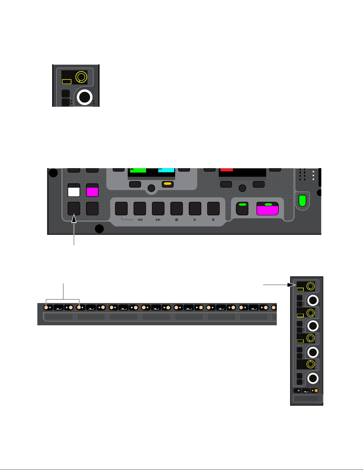
Adjusting Channel Parameters 111
The INPUT switch lights, the Input touch zone is bordered in orange, and Input parameters are spilled to the CKM.
2 Locate the encoder display showing Gain, and rotate the corresponding encoder.
The gain value changes in the encoder displays, in the Inputs zone of the MTS and CTM Universe view, and in the Input section
of the Inputs page for the channel on the external screen (if the selected channel is also attentioned).
To adjust channel input gain in Channel Strip mode:
1 Bank to the desired input channels.
2 Do either of the following to enable Channel Strip mode:
• Press a lit Select switch to de-select it and enable Channel Strip mode on the associated CKM.
• Press Select Clear to de-select all channels on the control surface and enable Channel Strip mode on all CKMs.
3 If necessary, navigate to the first Channel Strip mode parameter bank by pressing the lit Left Parameter Bank switch until Gain
appears in the top row encoder displays.
4 In the column for the channel you want to adjust, rotate the encoder under the display showing Gain The gain value in the dis-
play changes as you adjust the parameter.
Encoder display showing parameter and parameter value
Select Clear on the MLM
Lit Left Parameter Bank Switches (left) and the first page of Channel Strip parameters for input channels (right)
In
Sel
Gain
0.0 dB
PAD
Flip
Trans
F1 F2 F3 F4 F5
NEXT
PREV
Encoder
Assign
Select
Clear
Tap
Tempo
30
21
Next
Mute Group 6
M6
VCA 9-16
9-16
Ch 81-96
81-96
MIXMIXMIXPLUG-INSDYNAMICSEQINPUTCHANNEL
CHANNEL
In
Sel
In
Sel
In
Sel
In
Sel
HPF
20 Hz
Gain
0.0 dB
LPF
20.00 kHz
<0>
Pan
PAD
IN
IN

Adjusting Channel Parameters 112
Using Gain Guess
The automated Gain Guess function can be used to set a nominal level for a channel based on its incoming signal. When you en-
abled Gain Guess, the system samples the incoming signal and automatically sets the channel Input Gain and pad for a 0 dB refer-
ence. Gain Guess follows the current Meter mode (Peak or RMS). You can access Gain Guess on the external screen.
To engage Gain Guess:
1 On the external screen, go to the Inputs page.
2 Attention a channel.
3 Touch and hold the Guess button. The button flashes to indicate level sampling.
4 Release the button. Input Gain will be set so the incoming signal reaches 0 dB peak (if Peak mode is selected) or 0 dB RMS (if
RMS mode is selected).
Setting Right Offset on Stereo Channels
On stereo input channels the Gain control affects both the left and right channels. The Right Offset feature lets you offset the gain
of the right channel relative to the left channel by –20 dB to +20 dB, within the overall gain limits. You can adjust Right Offset in
Channel Control and Channel Strip modes.
To adjust Right Offset in Channel Control mode:
1 Bank to the desired input channels, then do either of the following:
• Select a channel, and then press the INPUT Channel Control Function switch on the associated CKM.
• On the associated CTM, touch the Input touch zone for the desired channel.
2 Rotate the encoder under the display showing R. Offset.
To adjust Right Offset in Channel Strip mode:
1 Bank the desired input channels.
2 Enable Channel Strip mode on the CKMs by doing either of the following:
• Press a lit Select switch to enable Channel Strip mode on the associated CKM.
• Press Select Clear to de-select all channels on the control surface and enable Channel Strip mode on all CKMs.
3 If necessary, navigate to the first Channel Strip mode parameter bank by pressing any lit Left Parameter Bank switches until
Gain appears in the top row encoder displays.
4 In the column for the channel you want to adjust, press the encoder Sel switch under the display showing Gain. R. Offset is now
shown in the display, and the encoder targets the Right Offset parameter.
5 Rotate the encoder under the display showing R. Offset to adjust the Right Offset. The gain value in the display changes as you
adjust the parameter.
Gain Guess engaged

Adjusting Channel Parameters 113
20 dB Pad
Analog Input Channels Only
You can apply a 20 dB pad to any analog input assigned to an input channel in Channel Control and Channel Strip modes.
To toggle a channel pad in/out in Channel Control mode:
1 Bank to the desired input channels.
2 Select a channel, and then press the INPUT Channel Control Function switch on the associated CKM.
– or –
• On the associated CTM, touch the Input touch zone for the desired channel.
3 Press the encoder under the display showing Pad. When the pad is engaged, the encoder surround in the display fills in, PAD
lights in the display, and the encoder
In LED lights green.
To toggle a channel pad in/out in Channel Strip mode:
1 Bank the desired input channels.
2 Do either of the following to enable Channel Strip mode:
• Press a lit Select switch to enable Channel Strip mode on the associated CKM.
• Press Select Clear to de-select all channels on the control surface and enable Channel Strip mode on all CKMs.
3 If necessary, navigate to the first Channel Strip mode parameter bank by pressing the lit Left Parameter Bank switch until Gain
appears in the top row encoder displays.
4 In the column for the channel you want to adjust, press the encoder In switch under the display showing Gain. The In LED lights
green to indicate the Pad is in.
48 V (Phantom Power)
Input Channels Only
You can apply 48 V phantom power to any analog input assigned to an input channel in Channel Control mode.
To apply 48 V:
1 Bank to the desired input or output channels.
2 Select a channel, and then press the INPUT Channel Control Function switch on the associated CKM.
– or –
• On the associated CTM, touch the Input touch zone for the desired channel.
3 Press the encoder under the display showing 48 V. The encoder surround in the display fills in, 48V lights in the display, and the
encoder In LED lights green to indicate that 48 V is active on that channel.
Delay
You can apply up to 250 ms of delay to an input channel, or up to 500 ms of delay to an output channel (except VCAs) in Channel
Control mode.
To delay to a channel:
1 Bank to the desired input channels.
2 Select a channel
3 Press the INPUT Channel Control Function switch on the associated CKM.
4 To engage channel delay, press the encoder under the display showing Delay so IN is lit in the display.
5 Rotate the encoder to adjust the delay time.
Delay can be shown in milliseconds. feet, meters, or samples. See
Tap Tempo.

Adjusting Channel Parameters 114
Pan/Balance/Width
Pan adjusts channel pan (for mono channels) and stereo balance (for stereo channels). On stereo channels, width controls are also
provided. You can adjust pan controls for input channels, Aux outputs and Group outputs in Channel Control and Channel Strip
modes.
To adjust pan in Channel Control mode:
1 Bank to the desired input or output channels.
2 Select a channel, and then press the INPUT Channel Control Function switch on the associated CKM.
– or –
• On the associated CTM, touch the Input touch zone for the desired channel.
3 Rotate the encoder under the display showing Pan (mono channel) to adjust pan, or Balance (stereo channels) to adjust balance.
To adjust pan in Channel Strip mode:
1 Bank the desired input channels.
2 Do either of the following to enable Channel Strip mode:
• Press a lit Select switch to de-select it and enable Channel Strip mode on the associated CKM.
• Press Select Clear to de-select all channels on the control surface and enable Channel Strip mode on all CKMs.
3 If necessary, navigate to the first Channel Strip mode parameter bank by pressing the lit Left Parameter Bank switch until Pan
(or Balance for stereo channels) appears in the bottom row encoder displays.
4 In the column for the channel you want to adjust, rotate the encoder under the display showing Balance.
Stereo Width
Stereo Channels Only
Width adjusts the stereo image of stereo channels by controlling ganged pan positions of the left and right channels, in opposite di-
rections. Width can be adjusted from full L–R, to mono, to full inversed R-L. You can adjust width controls for stereo channels only
in Channel Control and Channel Strip modes.
To adjust width in Channel Control mode:
1 Bank to the desired input or output channels.
2 Select a channel, and then press the INPUT Channel Control Function switch on the associated CKM.
– or –
• On the associated CTM, touch the Input touch zone for the desired channel.
3 Rotate the encoder under the display showing Width.
To adjust width in Channel Strip mode:
1 Bank the desired input channels.
2 Do either of the following to enable Channel Strip mode:
• Press a lit Select switch to de-select it and enable Channel Strip mode on the associated CKM.
• Press Select Clear to de-select all channels on the control surface and enable Channel Strip mode on all CKMs.
3 If necessary, navigate to the first Channel Strip mode parameter bank by pressing the lit Left Parameter Bank switch until Bal-
ance appears in the bottom row encoder displays.
4 In the column for the channel you want to adjust, under the display showing Balance press the encoder Sel switch. Width is
shown in the display, and stereo width is now targeted to the encoder.
5 Rotate the encoder to adjust stereo width.
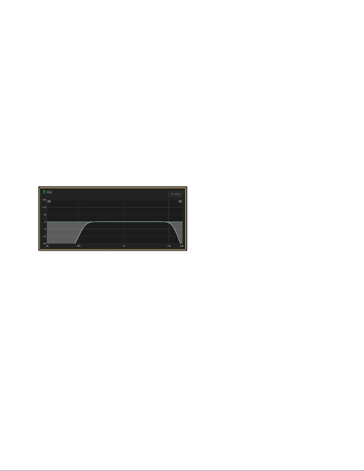
Adjusting Channel Parameters 115
High- and Low-Pass Filters (HPF and LPF)
Input Channels Only
The S6L system provides built-in 4th-order full-spectrum high- and low-pass filters on each input channel. You can adjust HPF and
LPF on the CKMs in Channel Control and Channel Strip mode using the Input or EQ functions.
To adjust HPF and LPF in Channel Control mode:
1 Bank to the desired input channels.
2 Select a channel, and then press the INPUT or the EQ Channel Control Function switch on the associated CKM.
– or –
• On the associated CTM, touch the Input or EQ touch zone for the desired channel.
3 To engage the filters on the channel, press the encoders under the displays showing HPF (for the high-pass filter) and LPF (for
the low-pass filter), as desired. Each filter’s corresponding encoder
In switch lights to indicate that the filter is engaged, and IN
lights in the corresponding display.
4 To adjust the frequency, rotate encoders as follows:
• Rotate the HPF encoder to the right to raise the filter’s corner frequency from its default starting frequency of 20 Hz.
• Rotate the LPF encoder to the left to lower the filter’s corner frequency from its default starting frequency of 20 kHz
Filtering is shown on-screen in the EQ section of the MTS and CTM Universe view, and in the EQ section of the Inputs page for
the channel on the external screen (if the selected channel is also attentioned).
To adjust HPF and LPF in Channel Strip mode:
1 Bank the desired input channels.
2 Do either of the following to enable Channel Strip mode:
• Press a lit Select switch to de-select it and enable Channel Strip mode on the associated CKM.
• Press Select Clear to de-select all channels on the control surface and enable Channel Strip mode on all CKMs.
3 If necessary, navigate to the first Channel Strip mode parameter bank by pressing the lit Left Parameter Bank switch until HPF
and LPF appear in the second and third row encoder displays.
4 Press the encoders under the displays showing HPF (for the high-pass filter) and LPF (for the low-pass filter), as desired, to en-
gage the filters on the channel. Each filter’s corresponding encoder
In switch lights to indicate that the filter is engaged.
5 Rotate each filter’s corresponding encoder to adjust the filter.
EQ section of the MTS Universe view showing high- and low-pass filtering on a channel

Adjusting Channel Parameters 116
Polarity Invert
(Phase Reverse)
You can invert the polarity of input channels, Aux outputs, Group outputs, and the Mains. With stereo channels, only the left chan-
nel is inverted. With Mains, regardless of the linked state of the Mains buses, polarity is inverted on both the Left and Right buses,
Polarity is inverted on the C/Mono bus independently of the Mains Left and Right.
To invert the polarity in Channel Control mode:
1 Bank to the desired input or output channels.
2 Select a channel, and then press the INPUT Channel Control Function switch on the associated CKM.
– or –
• On the associated CTM, touch the Input touch zone for the desired channel.
3 Press the encoder below the display showing Polarity. The encoder surround in the display fills in and the encoder In LED lights
green to indicate that the polarity is now inverted on that channel.
Direct Outs
You can turn on and adjust the level of Direct Outputs of input channels, Auxes, Groups, Matrixes, and Mains using the CKM in
Channel Control mode. Channels are patched to hardware outputs or Pro Tools outputs using the Directs tab of the Patchbay on the
external screen (See Patching Direct Outputs). You can also adjust Direct Outputs on the external screen Inputs and Output
pages. Up to 12 dB of gain can be added to the Direct Output signal.
To adjust Direct Outs in Channel Control mode:
1 Bank the desired input or output channels.
2 Select a channel, and then press the INPUT Channel Control Function switch on the associated CKM.
– or –
• On the associated CTM, touch the Input touch zone for the desired channel.
3 To turn on the channel’s Direct Out, press the encoder under the display showing Dir Out. The encoder In LED lights green.
4 Rotate the encoder to adjust the Direct Out level of the channel.
Pro Tools Input Source Toggle (Virtual Soundcheck Input)
(Input Channels Only)
You can toggle the input source for the currently selected input channel between a Pro Tools Virtual Soundcheck input and the
Stage input source for the channel, letting you toggle individual channels between Virtual Soundcheck and Stage mode. This pa-
rameter mirrors the function of the
Source Channel Menu option, available on the channel strip.
To toggle the input source for an input channel in Channel Control mode:
1 Bank the desired channel to the faders.
2 Select a channel, and then press the INPUT Channel Control Function switch on the associated CKM so it lights.
– or –
• Touch the channel’s Input touch zone on the associated Channel Touch Module (CTM).
3 Press the encoder under the display showing PT Input. The encoder In switch lights, and the encoder surround in the display fills
in to indicate the Pro Tools Virtual Soundcheck input is now the input source for the selected channel.
Direct Out level can also be assigned to faders by defining
Events with the Continuous Control on Faders action.
You can also toggle input using the Channel Menu and the external screen. See the S6L Live Recording Guide.pdf for more
information,
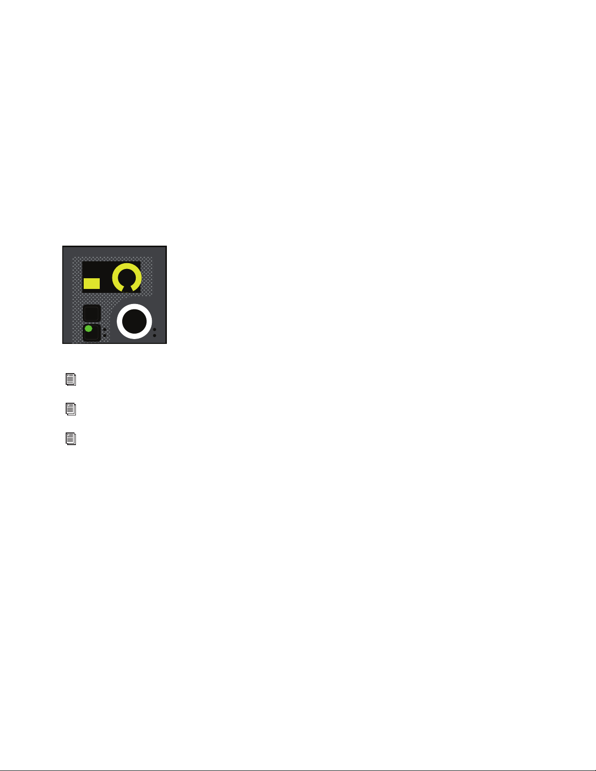
Adjusting Channel Parameters 117
Safe
You can toggle a selected input channel’s Bank, Automation, and Solo Safe, and a selected output channel’s Bank and Automation
Safe from the CKM in Channel Control mode. These Safe controls are independent of the global Channel Safe Switches settings
on the
Options > Interactions page of the external screen.
To toggle a channel Safe:
1 Bank to the desired input or output channels to the faders.
2 Select a channel, and then press the INPUT Channel Control Function switch on the associated CKM so it lights.
– or –
• Touch the channel’s Input touch zone on the associated Channel Touch Module (CTM).
3 Locate the encoder showing the Safe you want to toggle, then press it. The encoder In switch lights, the encoder surround in the
display fills in to indicate the Safe is enabled, and ON is lit in the display.
For example, to enable Bank Safe, press the encoder under the display showing
Bank Sf on the encoder display.
The encoder In switch lights green, and the channel is Bank Safed.
Bank Safe parameter on a CKM encoder
For more information on Bank Safe, see
Bank Safing Channels.
For more information on Solo Safe, see
Solo Safing Channels.
For more information on Automation Safe, see
Automation Safing Channels.
In
Sel
Bank Sf
ON
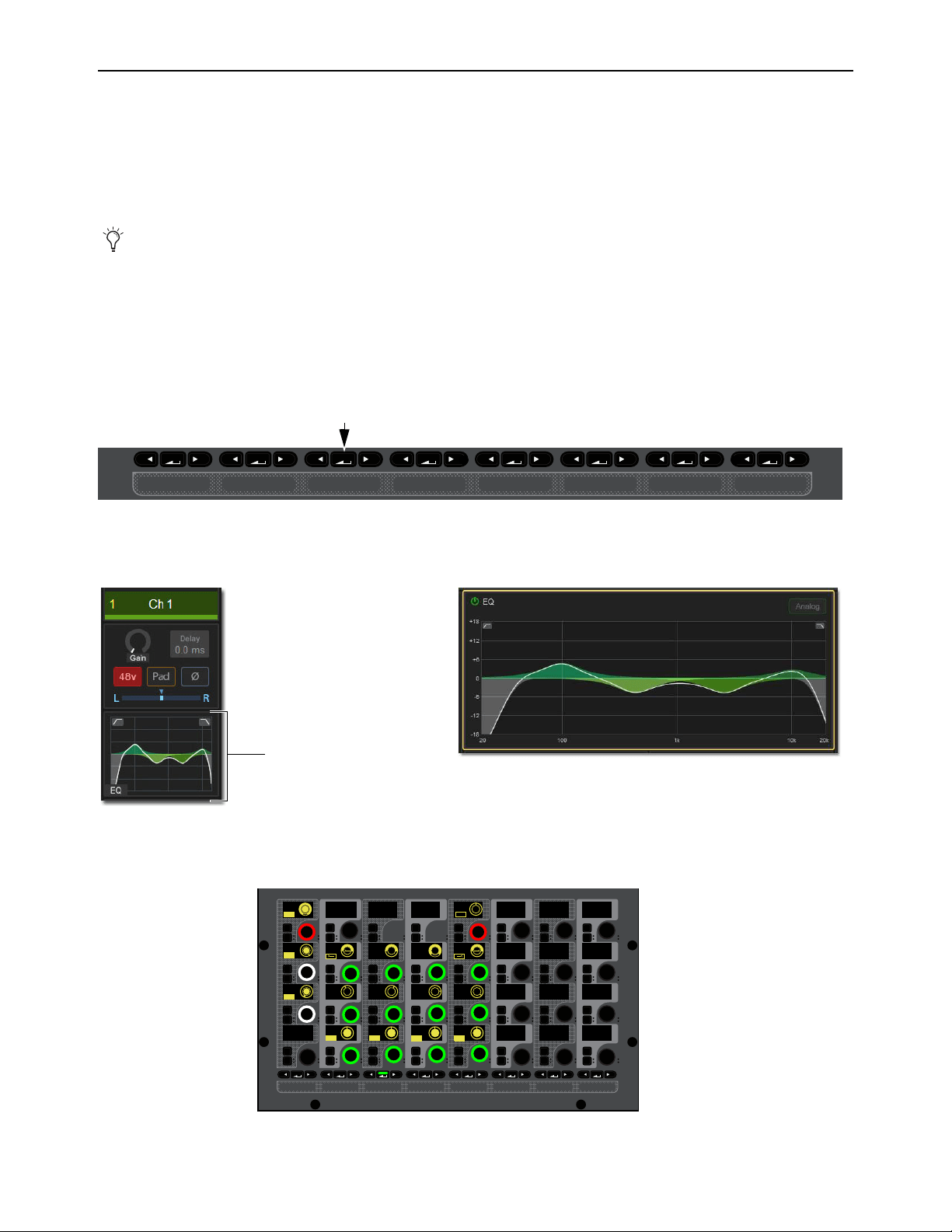
Adjusting Channel Parameters 118
Adjusting EQ
on the Control Surface
Each input channel has a built-in 4-band EQ. Each output channel (except VCAs) has a built-in 7-band parametric EQ. You can
choose between two EQ types on a per-channel basis: a full-spectrum digital EQ or an analog-modeled EQ. You can adjust channel
EQ on the CKMs in Channel Control mode. You can also adjust channel EQ band gain in Channel Strip mode.
S6L systems also provide 32 built-in insertable graphic EQs (GEQ) for output channels. You can adjust Graphic EQs inserted on
output channels using the CKMs in Channel Control mode.
Adjusting Channel EQ on the Control Surface
To adjust built-in channel EQ in Channel Control mode:
1 Bank to the desired input or output channels.
2 Select a channel, and then press the EQ Channel Control Function switch on the associated CKM.
– or –
• Touch the EQ touch zone for the desired channel on the associated CTM in Meters or Channel view.
The
EQ Channel Control Function switch lights, the EQ touch zone is bordered in orange, and EQ parameters are spilled to the
associated CKM.
You can also adjust EQ using the external screen, as well as accomplish other tasks including toggling digital and analog EQ
modes, copy and paste EQ settings between channels, and save and recall EQ presets. See
Working with EQ and Dynam-
ics on the External Screen.
INPUT Channel Control Function switch (left) and the Input touch zone in the CTM Meters view (right)
EQ touch zones on the CTM in Meters view (left) and in Channel view (right)
Built-in 4-band EQ parameters on the CKM
MIXMIXMIXPLUG-INSDYNAMICSEQINPUTCHANNEL
MIXMIXMIXPLUG-INSDYNAMICSEQINPUTCHANNEL
In
Sel
In
Sel
In
Sel
In
Sel
In
Sel
In
Sel
In
Sel
In
Sel
In
Sel
In
Sel
In
Sel
In
Sel
In
Sel
In
Sel
In
Sel
In
Sel
In
Sel
In
Sel
In
Sel
In
Sel
In
Sel
In
Sel
In
Sel
In
Sel
In
Sel
In
Sel
In
Sel
In
Sel
In
Sel
In
Sel
In
Sel
In
Sel
IN IN IN IN
IN
IN
IN
IN
ON
ON
ON
ON
IN IN
IN IN
EQ In Analog
Hi Gain
Hi Freq
HM Freq
LM Freq
Lo Freq
Lo Q
1.00
200 Hz 1.00 kHz 5.00 kHz
10.00 kHz
0.0 dB
0.0 dB
0.0 dB
0.0 dB
1.00 1.00 1.00
LM Q
HM Q
Hi Q
HM Gain
LM Gain
Lo Gain
LPF
HPF
80 Hz
20.00 kHz
IN IN
IN IN
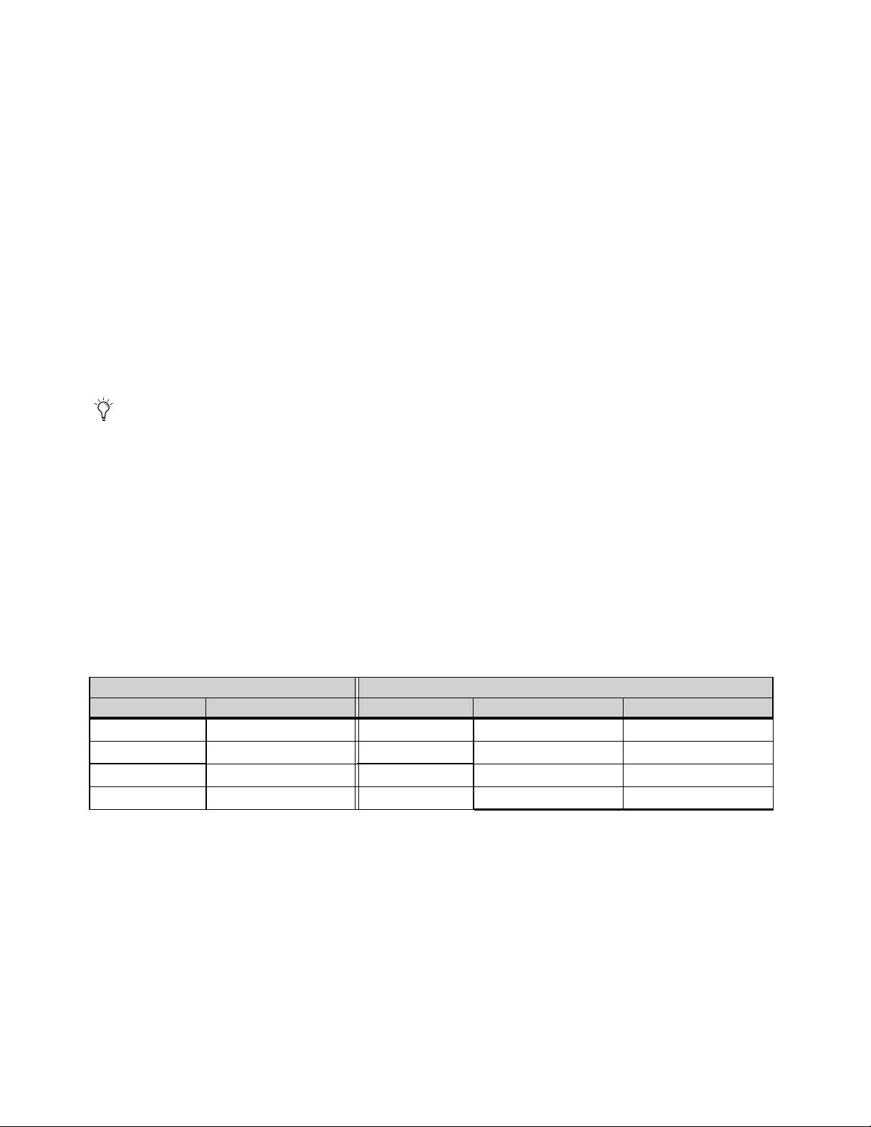
Adjusting Channel Parameters 119
To toggle the processor in/out,
Press the red encoder at the top left of the CKM, under the display showing EQ In.
The encoder In switch lights, and the encoder surround in the display fills in to indicate the EQ is engaged.
To toggle individual EQ bands in/out:
Press the encoder In switch below the display showing EQ band gain (the encoders along the bottom row of the CKM). An EQ
band is in when the switch lights.
To adjust EQ bands:
1 To adjust EQ band gain, under the displays showing Lo Gain, LM Gain, and so on rotate the desired encoder.
2 To adjust EQ band frequency, under the displays showing Lo Freq, LM Freq, and so on rotate the desired encoder.
3 To adjust EQ band Q, under the displays showing Lo Freq, LM Freq, and so on rotate the desired encoder.
4 To toggle between Bell and Shelf filters for the Hi and Lo bands:
• Press the encoder In switch below the display showing Hi Q to toggle Shelf on the Hi EQ band.
• Press the encoder In below the display showing Lo Q (or Lo 1 Q for outputs) to toggle Shelf on the Lo 1 EQ band.
Shelf is active when the encoder In switch lights.
To adjust EQ band gain in Channel Strip mode:
1 Bank the desired input or output channels.
2 Do either of the following to enable Channel Strip mode:
• Press a lit Select switch to de-select it and enable Channel Strip mode on the associated CKM.
• Press Select Clear to de-select all channels on the control surface and enable Channel Strip mode on all CKMs.
3 Navigate to the EQ Channel Strip mode parameter bank by pressing a lit Parameter Bank switch, as available, until the encoders
appear green.
When a CKM is in Channel Strip mode and displaying EQ parameters, the encoder SEL switches assign EQ Frequency to the
corresponding encoder. Press SEL again to return the encoder to band Gain.
EQ band gain parameters for input channels appear on the second page of Channel Strip mode parameters, and pages two and
three for output channels, as follows:
For input channels, HPF and LPF parameters are also provided along with EQ parameters.
Channel Strip mode EQ parameters available per channel type
Input Channels Output Channels
CKM Encoder Page 2 CKM Encoder Page 2 Page 3
1 (top) EQ Hi Gain 1 (top) EQ Lo Mid 2 Gain n/a
2 EQ Hi Mid Gain 2 EQ Lo Mid 1 Gain EQ Hi Gain
3 EQ Lo Mid Gain 3 EQ Lo 2 Gain EQ Hi Mid 2 Gain
4 (bottom) EQ Lo Gain 4 (bottom) EQ Lo 1 Gain EQ Hi Mid 1 Gain
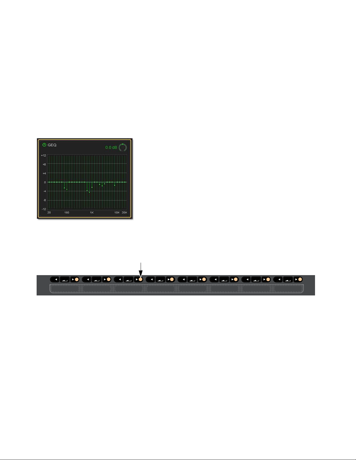
Adjusting Channel Parameters 120
Adjusting Graphic EQ on the Control Surface
(Output Channels Only)
GEQ parameters can be adjusted on CKMs or from the faders.
Adjusting GEQ on the CKM
To access GEQ parameters on the CKM, you must first insert a GEQ on the channel on the Outputs page of the external screen. See
Adjusting Graphic EQ on the External Screen.
To adjust GEQ in Channel Control mode:
1 Bank to the desired channels.
2 Select a channel, and then press the EQ Channel Control Function switch on the associated CKM.
– or –
• Touch the GEQ touch zone for the desired channel on the associated CTM in Meters or Channel view.
The EQ Channel Control Function switch lights, the EQ touch zone is bordered in orange, and channel EQ parameters are spilled
to the associated CKM.
3 Press any lit Right Parameter Bank Navigation switch.
GEQ parameters are spilled to all 4 rows of CKM encoders. Each individual band gain is assigned to an encoder.
4 To enable the GEQ, press the red encoder under the display showing In/Gain.
5 To adjust the overall output of the GEQ, rotate the red encoder.
6 To adjust individual band gain, rotate the corresponding encoders.
GEQ touch zones in Channel view
Lit Right Parameter Bank switches
MIXMIXMIXPLUG-INSDYNAMICSEQINPUTCHANNEL

Adjusting Channel Parameters 121
Adjusting GEQ on Faders
You can access an inserted Graphic EQ on the faders using the MLM Right Soft Keys, and using events to assign a Function switch
that banks GEQ to the faders.
On S6L-32D systems, 31 bands of GEQ are available; on S6L-24D and S6L-24, the MLM Bank switches let you access other
bands.
To access GEQ on Faders using the MLM Soft Keys:
1 Make sure the Right Soft Keys on the MLM are set to their Home view.
2 Press the Soft Key for GEQ on Faders.
3 To exit GEQ on Faders mode, press the GEQ on Faders Soft Key again.
To create an event for GEQ on Faders:
1 On the external screen, go to the Media page to show the Events screen.
2 To create an empty, untitled new event, do the following:
• Click the New button in the Event Commands section.
• Double-click the new event in the Events List and enter a name such as GEQ on Faders.
3 With the new event selected (highlighted in the Events List), click the ADD pop-up menu in the Triggers list and select the trigger
type, such as Function Switch 9. The selected trigger type is added to the Trigger list for the currently selected event, with its
default properties.
4 Click the ADD pop-up menu in the Action list and select GEQ on Faders.
To access GEQ on Faders using an event:
1 Attention an Output Channel with a GEQ inserted on it.
2 Engage the trigger you selected to trigger GEQ on faders.
GEQ bands are spilled across all faders.
• On S6L-32D systems, all bands spill across the faders.
• On S6l-24D and S6L-24 systems, up to 24 bands spill across the faders. On the external screen, banked bands are lit white.
To bank to the next or previous set of GEQ bands, press the lit
< Bank > switches or use the Soft Keys to select the desired
bands.
3 To access GEQ on a different channel, Attention that channel using the MTS Attention key (the channel must already have a
GEQ inserted).
To cancel GEQ on Faders:
Press the flashing Cancel switch.
For more information on using the features of the Events screen, see
Events.
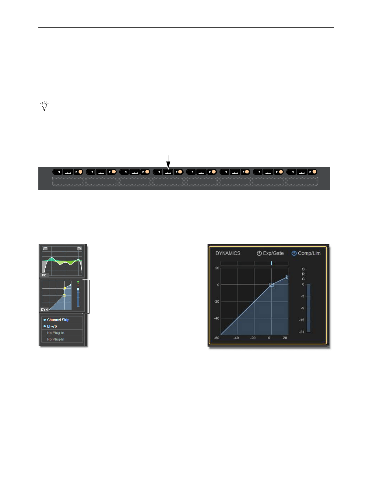
Adjusting Channel Parameters 122
Adjusting Dynamics on the Control Surface
All input and output channels provide a built-in Compressor Limiter (Comp/Lim), and input channels provide an Expander/Gate
(Exp/Gate). Both built-in and most plug-in dynamics processors support sidechain processing.
For stereo channels, processor controls are linked and apply to both the left and right sides of the channel. For Mains L-R, processor
controls are linked regardless of the Mains linked/unlinked state. Dynamics control for the C/Mono bus is always discrete.
You can adjust built-in Dynamics in Channel Control and Channel Strip modes. You can also toggle built-in Dynamics processors
in/out using the channel strip
X and Y switches.
To adjust built-in Dynamics in Channel Control mode:
1 Bank the desired input or output channels.
2 Select a channel, and then press the DYNAMICS Channel Control Function switch on the associated CKM.
– or –
• Touch the Dynamics touch zone for the desired channel on the associated CTM in Meters or Channel view.
The DYNAMICS Channel Control Function switch lights, the Dynamics touch zone is bordered in orange, and Dynamics pa-
rameters are spilled to the associated CKM.
You can also adjust Dynamics, including the sidechain, using the external screen. See
Working with EQ and Dynamics on the
External Screen.
Dynamics Channel Control Function switch
Dynamics touch zones on the CTM in Meters view (left) and in Channel view (right)
MIXMIXMIXPLUG-INSDYNAMICSEQINPUTCHANNEL
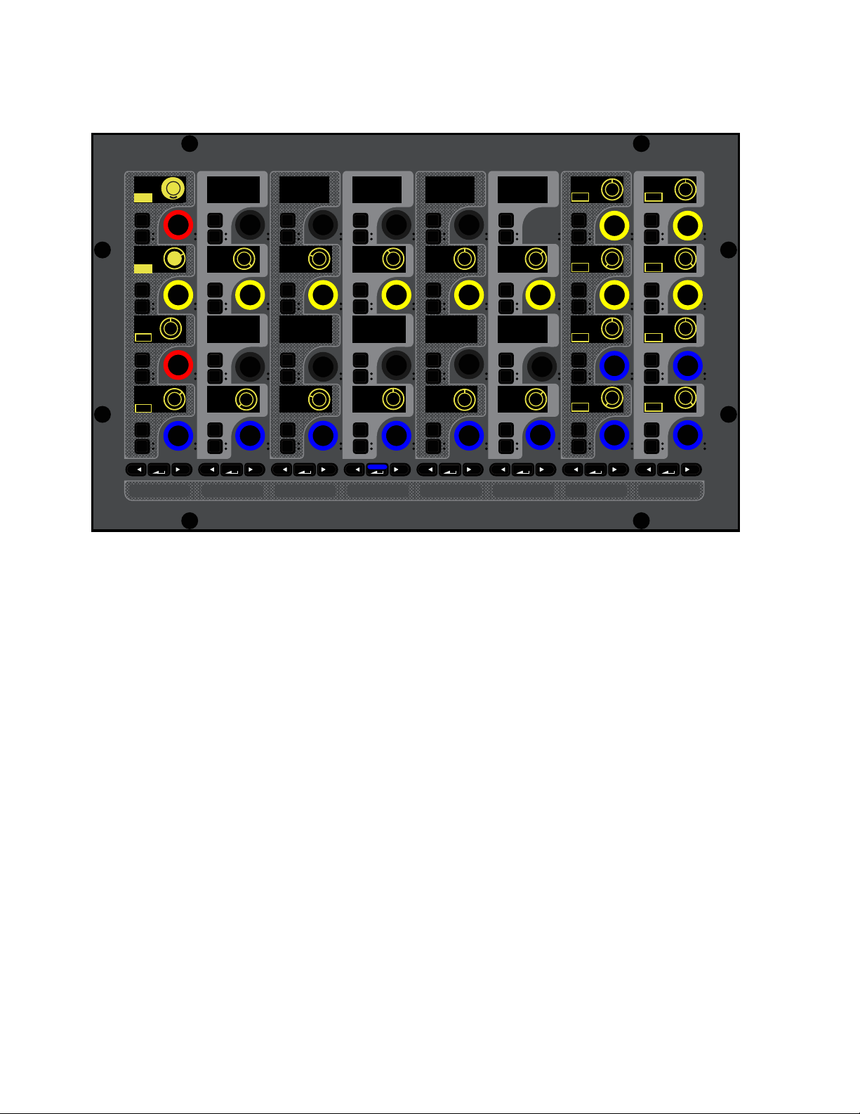
Adjusting Channel Parameters 123
For input channels, Exp/Gate parameters are assigned to the top two rows of encoders, and Comp/Lim parameters are assigned
to the bottom two rows.
For output channels, Comp/Lim parameters are assigned to the bottom two rows.
3 To toggle Dynamics processors in/out, do any of the following:
• To toggle Exp/Gate, press the red encoder under the display showing E/G In. When engaged (in), the encoder In switch lights,
and the encoder surround in the display fills in.
• To toggle Comp/Lim, press the red encoder under the display showing
C/L In. When engaged (in), the encoder In switch
lights, and the encoder surround in the display fills in.
4 To adjust parameters, rotate the encoder under the display showing the parameter you want to adjust.
Gain reduction and gate activity is indicated on the channel strip gain reduction meters and in the Inputs zone on the associated
CTM. See
Dynamics Meter for more information.
To toggle Dynamics in/out using the X and Y switches:
Press a channel strip X switch to toggle the Exp/Gate for that channel. The switch lights when the processor is engaged (in).
Press a channel strip Y switch to toggle the Comp/Lim for that channel. The switch lights when the processor is engaged (in).
Sidechain
Dynamics processors typically use the detected amplitude of their input signal to trigger gain reduction. This split-off signal is
known as the sidechain. The built-in Comp/Lim and Exp/Gate feature sidechain circuits with external key and EQ filter capabili-
ties.
With sidechain EQ filters, you can make dynamics processing more or less sensitive to certain frequencies. For example, you might
configure the sidechain so that certain lower frequencies on a drum track trigger dynamics processing. You can engage and adjust
sidechain EQ filters on the CKM under the
DYNAMICS function.
With external key sidechain processing, dynamics processing is triggered using an external signal (such as another input) instead
of the input signal. This external source is known as the key input. Key input is selected in the Sidechain section of the Inputs or
Outputs page of the external screen (see
Selecting the External Key Sidechain Input).
Input channel Dynamics parameters on a CKM in Channel Control mode
MIXMIXMIXPLUG-INSDYNAMICSEQINPUTCHANNEL
In
Sel
In
Sel
In
Sel
In
Sel
In
Sel
In
Sel
In
Sel
In
Sel
In
Sel
In
Sel
In
Sel
In
Sel
In
Sel
In
Sel
In
Sel
In
Sel
In
Sel
In
Sel
In
Sel
In
Sel
In
Sel
In
Sel
In
Sel
In
Sel
In
Sel
In
Sel
In
Sel
In
Sel
In
Sel
In
Sel
In
Sel
In
Sel
E/G In
Ratio
100:1
0
1.00 ms 100 ms 250 ms
Attack
Hold
Release
Knee
C/L In
250 ms
Release
-20 dB
Range
0.0 dB
Gain
10 Hz
Key HPF
20.00 kHz
Key LPF
Key In KeyListn
10 Hz
Key HPF
20.00 kHz
Key LPF
Key In
KeyListn
Thrshld
-10.0 dB
Ratio
2:1 10.0 ms
AttackThrshld
0.0 dB
ON
ON
ON
ON
ON
ON
IN IN
IN IN
IN IN
IN
IN IN
IN IN
IN IN
IN IN
IN
ON
ON
ON
ON

Adjusting Channel Parameters 124
Engaging the Sidechain
The sidechain must be engaged to enable both external key and EQ filter sidechain processing for the selected channel. The Key
In control can be toggled in or out of circuit using the CKMs in Channel Control mode.
To toggle the sidechain:
1 Bank to the desired input or output channels.
2 Select a channel, and then press the DYNAMICS Channel Control Function switch on the associated CKM.
– or –
• Touch the Dynamics touch zone for the desired channel on the associated CTM in Meters or Channel view.
3 Press the encoder under the display showing Key In. When engaged (in), the encoder In switch lights, and the encoder surround
in the display fills in.
Using Sidechain EQ Filters
Both the Compressor/Limiter and the Expander/Gate sidechains provide two bands of EQ to band-limit the range of frequencies
that trigger dynamics processing.
To activate a sidechain EQ filter in Channel Control mode:
1 Bank to the desired input or output channels.
2 Select a channel, and then press the DYNAMICS Channel Control Function switch on the associated CKM.
– or –
• Touch the Dynamics touch zone for the desired channel on the associated CTM in Meters or Channel view.
3 Press the encoder under the display showing Key In. When engaged (in), the encoder In switch lights, and the encoder surround
in the display fills in.
4 Press the Channel Control encoder under the display showing Key HF and/or Key LF.
To adjust a side-chain EQ filter:
Turn the Key HF and/or Key LF encoders to adjust the frequency (each filter ranges from 10 Hz to 20 kHz). In the encoder dis-
plays, the current frequency value is displayed on-screen.
Key Listen
The Key Listen button toggles the key onto the Monitor bus, replacing the signal there. This happens regardless of whether the key
is the channel signal or the external key, or whether it has been sidechain filtered. Key Listen always overrides all other soloed
channels. Any soloed channels are suppressed until Key Listen is cleared. If additional channels are soloed while Key Listen is on,
they will be added but suppressed. The Key Listen solo is also exclusive to itself; pressing Key Listen on a different processor or
channel turns off the previous Key Listen and the new Key Listen takes over.
To engage Key Listen:
Press the encoder under the displays showing KeyListn. When engaged (in), the encoder In switch lights, and the encoder sur-
round in the display fills in.
To disengage Key Listen:
Press the encoder again so the encoder In switch is unlit. The Solo bus reverts to its previous signal (soloed channels, or none).
You can also press Solo Clear once to turn off any currently engaged Key Listen button. Press Solo Clear a second time to
clear channel solos, if any.
For frequency-dependent gating or compression, make sure the Key Source is set to Self. See
Selecting the External Key
Sidechain Input.
Key Listen on a dynamics plug-in does not route the signal to the Monitor bus, but to the plug-in output. Use caution when using
the Key Listen with a plug-in dynamics processor.
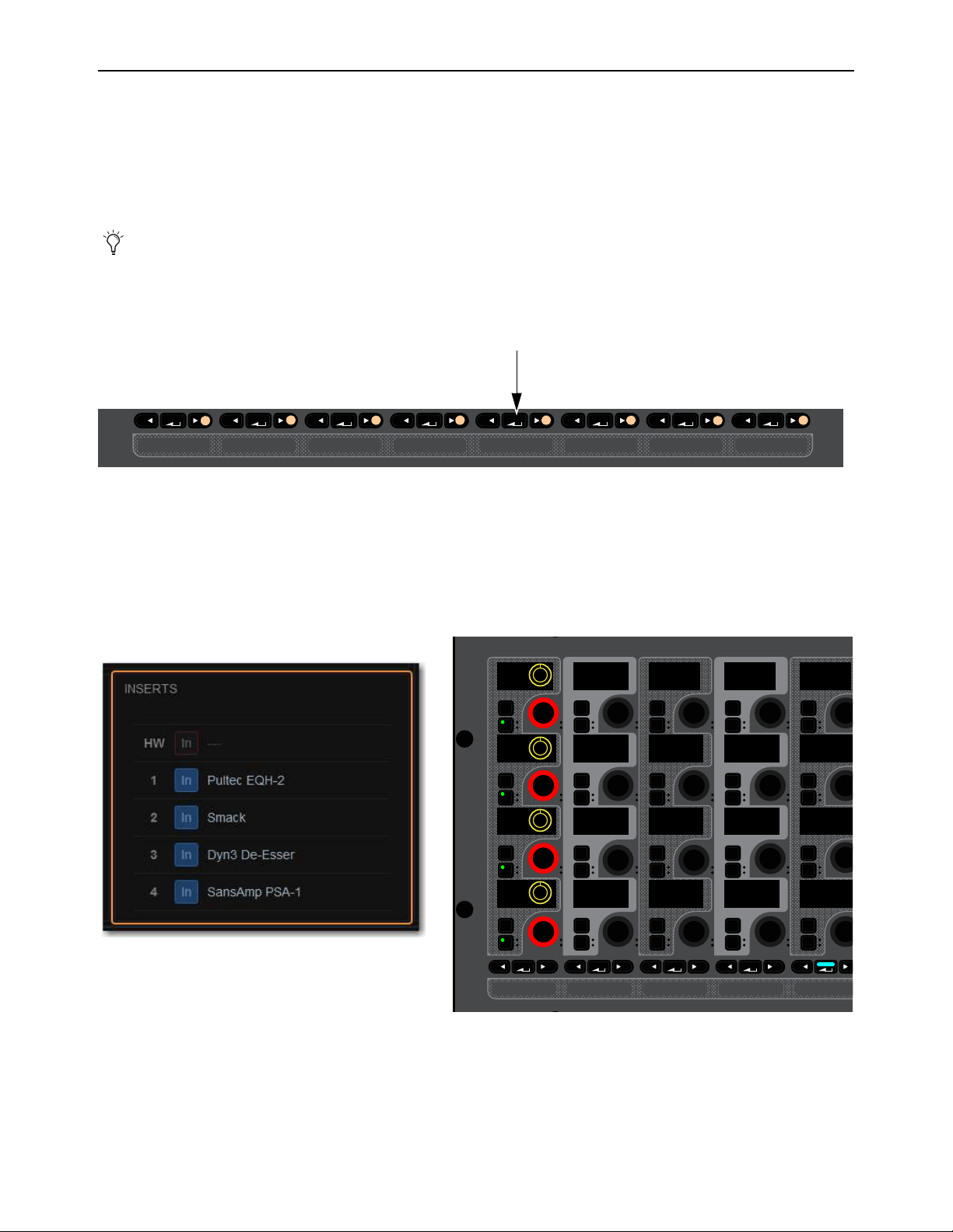
Adjusting Channel Parameters 125
Adjusting Plug-Ins on the Control Surface
You can adjust inserted plug-ins and bus-fed plug-ins using the CKMs.
Adjusting Inserted Plug-Ins
You can adjust the parameters of up to four inserted plug-ins using the CKMs in Channel Control mode. To access inserted plug-in
parameters on the CKM, one or more plug-ins must be inserted on the channel (see Inserting Plug-Ins on Channels).
To adjust plug-ins in Channel Control mode:
1 Bank to the desired input or output channels.
2 Select a channel with one or more inserted, and the press the Plug-Ins Channel Control Function switch on the associated CKM.
– or –
• Touch the Plug-Ins touch zone for the desired channel on the associated CTM in Meters or Channel view.
The PLUG-INS Channel Control Function switch lights and the Plug-Ins touch zone is bordered in orange.
Red Plug-In Selectors are assigned to the leftmost encoders of each row of encoders on the associated CKM. Each Plug-In Se-
lector corresponds to an Inserts slot 1–4 of the targeted channel, from top to bottom. If no plug-in is inserted into a slot,
No
Plug-In is displayed.
3 To access a plug-ins parameters, press a red Plug-In Selector encoder under the display showing the name of the desired plug-in.
The parameters for that plug-in are spilled to the encoders.
On-screen, the targeted plug-in is bordered in red in the Inserts section of the channel, and on the external screen Plug-Ins page.
You can also adjust plug-ins on the Plug-Ins page of the external screen. See
Adjusting Plug-Ins on the External Screen.
Plug-Ins Channel Control Function switch
Inserts section on-screen with Inserted plug-ins (left) and corresponding Plug-In Selectors on a CKM in Channel Control mode (right)
MIXMIXMIXPLUG-INSDYNAMICSEQINPUTCHANNEL
PLUG-INSDYNAMICSEQINPUTCHANNEL
In
Sel
In
Sel
In
Sel
In
Sel
In
Sel
In
Sel
In
Sel
In
Sel
In
Sel
In
Sel
In
Sel
In
Sel
In
Sel
In
Sel
In
Sel
In
Sel
In
Sel
In
Sel
In
Sel
In
Sel
Dn3Dsr
Smack
PlEQH2
SAPSA1
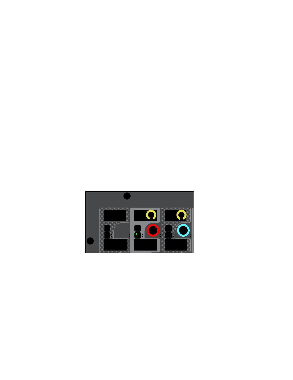
Adjusting Channel Parameters 126
To toggle an individual plug-in on/off
Press the encoder In switch for the corresponding Plug-In Selector. The following control surface and on-screen elements indi-
cate when a plug-in is engaged (in):
• The encoder In switch lights.
• On the CTM in Meters view and in the Channel Tiles in Channel view, in the Inserts zone a blue dot appears next to the
plug-in.
• On the MTS and the CTM in Meters view, in the Inserts zone the
On indicator for the plug-in lights blue.
To access another plug-in inserted on the same channel:
Press the corresponding red Plug-In selector encoder. The next time you access plug-ins on this channel, the parameters for the
last targeted plug-in are automatically spilled to the CKM encoders
Adjusting Bus-Fed Plug-Ins (Effect Returns)
You can adjust bus-fed plug-ins on the CKMs in Channel Control mode. You can adjust the bus-fed plug-in’s parameters, plus any
plug-ins inserted on the return channel. To access bus-fed plug-in parameters on the CKM, one or more plug-ins must be routed to
a channel (see Routing Plug-Ins as Bus Processors (Effect Send/Return).
To adjust a bus-fed plug-in:
1 Bank the channel to which the output of the bus-fed plug-in is routed to the faders
2 Select that channel, and then press the Plug-In Channel Control Function switch on the associated CKM.
– or –
• Touch the Plug-Ins touch zone for the desired channel on the associated CTM in Meters or Channel view.
The PLUG-INS Channel Control Function switch lights and the Plug-Ins touch zone is bordered in orange.
A red Plug-In Selector is assigned to the second encoder of the top row of encoders on the associated CKM, and plug-in param-
eters are spilled to the rest of the encoders.
3 Adjust parameters as desired.
To toggle the bus-fed plug-in on/off:
Press the encoder In switch for the corresponding Plug-In Selector.
To access plug-ins inserted on the return channel:
Press the corresponding red Plug-In selector encoder in the leftmost column. The parameters for that plug-in are spilled to the
encoders.
CKM with a bus-fed plug-in targeted to encoders
In
Sel
In
Sel
In
Sel
D-Verb Input
0.0 dB
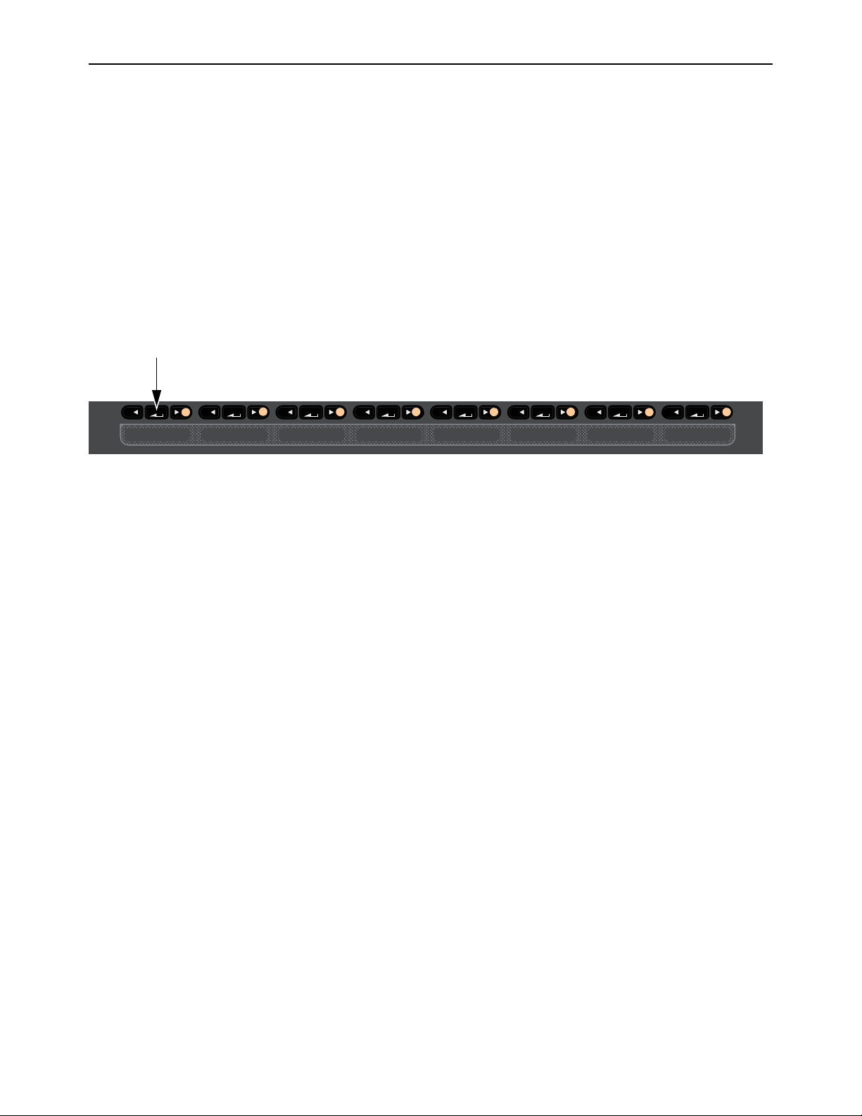
Adjusting Channel Parameters 127
Using the CHANNEL Function
The CHANNEL Channel Control Function switch assigns a variety of channel parameters such as input, EQ, and Dynamics pa-
rameters to the CKM in Channel Control mode, providing a default set of utility parameters for the selected channel. You can cus-
tomize this group of controls by assigning parameters to these encoders, up to a total of 32.
CHANNEL parameter encoder assignments are global, and apply to all channels. If an assigned parameter is not applicable for the
selected channel type, that encoder is blank. Plug-In parameters are not available for custom parameter assignments. Custom as-
signments are saved with each Show file.
Accessing CHANNEL Parameters
To access the default CHANNEL parameters:
1 Bank to the desired input or output channels.
2 Select a channel, and then press the CHANNEL Channel Control Function switch on the associated CKM. The default param-
eters are spilled to the CKM’s encoders.
Assigning Custom CHANNEL Parameters
You can customize the parameters that are spilled to the 32 CKM encoders when you press the CHANNEL Channel Control Func-
tion switch. A custom assignment replaces any existing assignments on the selected encoder. To assign parameters, enable User
Assignment mode on one CKM, then select the parameters you want to assign to
CHANNEL using another CKM.
To enable User Assignment mode:
1 Select a channel on any fader bank.
2 Press and hold the CHANNEL Channel Control Function switch on the associated CKM.
The CHANNEL switch flashes to indicate that the CKM is in User Assignment mode.
The top-left encoder flashes red to indicate it is now the target for the custom assignment.
3 Press an encoder on the CKM that is in User Assignment mode to target that encoder for the custom assignment. That encoder
now flashes.
4 On a CKM other than the one in User Assignment mode, do the following:
• Access the Channel Control function containing the parameter(s) you want to assign to CHANNEL.
• Touch the encoder for the parameter you want to assign.
That parameter is assigned to the targeted CHANNEL encoder.
The next encoder on the CKM in User Assignment mode flashes to indicate it is now the target for a custom assignments.
5 Repeat step 4 to assign other parameters to each targeted encoder.
6 When finished, press the flashing OK switch to confirm assignments and exit User Assignment mode.
– or –
• Press the flashing Cancel switch to cancel, leaving all assignments unchanged and exit User Assignment mode.
CHANNEL Channel Control Function switch
MIXMIXMIXPLUG-INSDYNAMICSEQINPUTCHANNEL
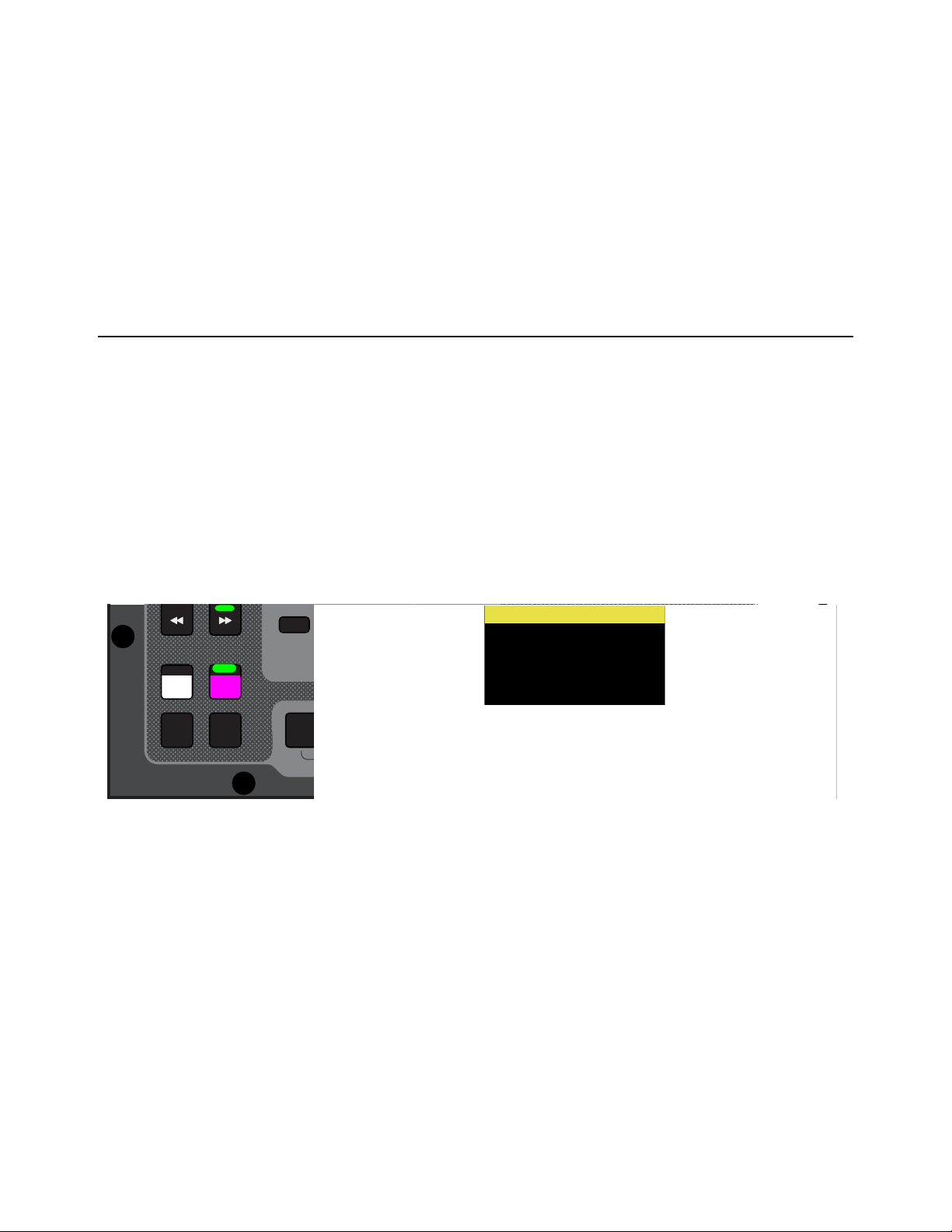
Adjusting Channel Parameters 128
Clearing CHANNEL Assignments
You can clear individual Channel Control assignments, or all assignments, on the Inputs and Outputs pages of the external screen.
To clear User assignments:
1 On the external screen, go to the Input or Outputs page.
2 Tap-and-hold (right-click) a parameter.
3 To clear a single parameter, choose Clear <parameter name> from the Channel Control sub-menu.
4 To clear all parameters, do the following:
• Choose Clear All Assignments.
•Select Clear to confirm, or select Cancel to cancel and leave the User assignment unchanged.
Flipping Parameters to Faders (Flip to Faders Mode)
Input Channels Only
You can flip a row of input channel parameters provided in Channel Strip mode to the faders, temporarily replacing channel level
control with control of the currently targeted parameter on the faders. You can enable Flip to Faders for input channels from any
CKM mode.
To flip parameters to faders:
1 Bank to the desired input channels to the faders
2 Press Flip so it lights (flashes).
The CKMs for all input channels enter Channel Strip mode.
The flashing row of encoders indicates the parameter that is currently flipped to faders.
3 Adjust the faders to change the parameter.
4 Touch an encoder in another row to flip that parameter to the faders.
– or –
• Press a lit Parameter Bank switch to navigate to another page of parameters, and then touch an encoder to flip its parameter
to the faders.
5 To exit Flip to Faders, press Flip again so it is unlit, or press Cancel.
When Flip to Faders is enabled again, the previously flipped row of encoders is flipped to the faders.
Flip switch enabled (left) and a channel display indicating that pan is flipped to faders (right)
Flip
Trans
F1 F2 F3 F4 F5
NEXT
PREV
Encoder
Assign
Select
Clear
Tap
Tempo
30
21
15
Next
Mute Group 5
Mute Group 6
M6
VCA 1-8
VCA 9-16
9-16
Ch 65-80
Ch 81-96
81-96
Ch 1
Pan
FLIP
Ch 1
Pan
FLIP

Adjusting Channel Parameters 129
Encoder Assign Mode
Encoder Assign mode lets you specify the parameters to display in each row of CKM knobs, letting you create and recall a custom
variation of (vertical) Channel Strip mode. For example, when mixing monitors you can use Encoder Assign mode to quickly ac-
cess wedge, side-fill, and sub sends for multiple channels.
You can create and save one custom Encoder Assignment per Show file.
To enter and use Encoder Assign mode from the control surface:
1 Press and hold Encoder Assign on the MLM for two or more seconds.
The Encoder Assign switch flashes white. On the far left CKM (or on
the only CKM on S6L-16C) the top row of encoders flash red, indicating
they are the target for encoder assignment.
• If no custom Encoder Assignment exists the displays on that CKM
will be unlit; if a previous Encoder Assignment exists, its assignments
are displayed.
• If any channel is on the left-most CFM of an S6L-32D or S6L-24D
currently selected, it is automatically unselected; on S6L-24C, any/all
selected channels are unselected.
2 On the other CKM(s), or on-screen, touch the knob for any input, EQ, dynamics, or bus continuous control. (Plug-in parameters
cannot be assigned.)
The selected parameter occupies the top row of the far left CKM, and the next row of knobs below it flashes red.
3 Repeat to assign other parameters to the remaining rows.
You cannot double-assign the same parameter to multiple rows (attempting to do so will blank out the currently targeted row and
advance to the next row).
4 When finished, press Encoder Assign again (or press OK on the MLM, or tap select Done in the Encoder Assignment alert
on-screen). The
Encoder Assign switch stops flashing.
5 To recall your custom Encoder Assignment and display it across all CKMs that are in vertical (Channel Strip), press Encoder
Assign (it lights white).
To edit a custom Encoder Assignment:
1 Press and hold Encoder Assign for two or more seconds until it flashes white.
2 On the left-most CKM, tap to select the row of knobs you want to edit (knobs in that row flash red).
3 Touch the desired parameter on the other CKM(s) or on-screen.
4 Press Encoder Assign again.
Encoder Assign mode enabled, with Input, Dyn, EQ, and Aux parameters assigned
VENUE | S6L
Solo Solo
Home
Config
VCAs
Outputs
Layouts
Inputs
Flip
Recall
Trans
F1 F2 F3 F4 F5
NEXT
PREV
Store
Y
X
Y
X
AFL
Dim
In
Sel
SNAPSHOTS
Talk
Back
Multi
Select
Encoder
Assign
Select
Clear
Tap
Tempo
Multi
Assgn
Default Fine
OK Cancel
Over
Write
Mix to
Mon
Solo
Clear
60
40
30
20
10
5
0
6
12
60
40
30
20
10
5
0
6
12
8All
Preview
ASSIGNABLE ENCODER MONITORING
Push A/BHold SIP
SHIFT
ALT
CTRL
ESC
Mute Mute
A
B
Nom
30
21
15
9
3
0
3
9
15
30
21
15
9
3
0
3
9
15
Inputs/Outputs
Next
Global Controls
0.0 dB
L
Left
0.0 dB
Kick
Mute Group 1
Mute Group
Function KeysMute Group 2
Mute Group 3
Mute Group 4
Mute Group 5
Mute Group 6
M1
M2
M3
M4
M5
M6
001/011
reset all inputs
0.0 dB
CH 1
Kick
Ch 1-16
1-16
Aux 1-8
1-8
Aux 9-16
Aux 17-24
Aux 25-32
25-32
VCA 1-8
1-8
VCA 9-16
9-16
Ch 17-32
17-32 9-16
Ch 33-48
33-48 17-24
Ch 49-64
49-64
Ch 65-80
65-80
Ch 81-96
81-96
S1Cu2
001 3
P:S1C1
N:S1C3
S1Cu3
S1Cu2
MIXMIXMIXPLUG-INSDYNAMICSEQINPUTCHANNEL
In
Sel
In
Sel
In
Sel
In
Sel
In
Sel
In
Sel
In
Sel
In
Sel
In
Sel
In
Sel
In
Sel
In
Sel
In
Sel
In
Sel
In
Sel
In
Sel
In
Sel
In
Sel
In
Sel
In
Sel
In
Sel
In
Sel
In
Sel
In
Sel
In
Sel
In
Sel
In
Sel
In
Sel
In
Sel
In
Sel
In
Sel
In
Sel
Gain
HPF
Gain
HPF
Gain
HPF
Gain
HPF
Gain
HPF
Gain
HPF
Gain
HPF
Gain
HPF
Gain
0.0 dB
Gain
0.0 dB
Gain
0.0 dB
Gain
0.0 dB
Gain
0.0 dB
Gain
0.0 dB
Gain
0.0 dB
Gain
0.0 dB
Thrshld
0.0 dB
ON
ON
Thrshld
0.0 dB
ON
ON
Thrshld
0.0 dB
ON
ON
Thrshld
0.0 dB
ON
ON
Thrshld
0.0 dB
ON
ON
Thrshld
0.0 dB
ON
ON
Thrshld
0.0 dB
ON
ON
Thrshld
0.0 dB
ON
ON
IN
0.0 dB
Lo Gain
IN
IN
0.0 dB
Lo Gain
IN
IN
0.0 dB
Lo Gain
IN
IN
0.0 dB
Lo Gain
IN
IN
0.0 dB
Lo Gain
IN
IN
0.0 dB
Lo Gain
IN
IN
0.0 dB
Lo Gain
IN
IN
0.0 dB
Lo Gain
IN
Aux 1 Aux 1 Aux 1
-10.0 dB -20.0 dB -10.0 dB
-20.0 dB
Aux 1
-INF
Aux 1
-INF
Aux 1
-INF
Aux 1
-INF
Aux 1
Pre
Pre Pre
Pre Pre
Pre
Pre
Pre
ON
ON
ON
ON ON ONON
ON
Flip
Encoder
Assign
Select
Clear
Tap
Tempo

Working with Mains and VCAs 130
Working with Mains and VCAs
Working with Mains
You can adjust Mains on the S6L control surface using the Flex Channels and the channel strips, and on the external screen. You
can solo, mute, and attention Mains, as well as target Mains for a Multi-Assignment using the MTS.
By default, level and mute for all three Mains buses are linked. You can unlink any Mains channel to independently control level
and mute. See
Linking/Unlinking Mains. Channel processing (such as EQ and dynamics) for Mains L-R are always linked.
C/Mono is always processed independently of Mains L-R.
Adjusting Mains Using the Flex Channels
By default, Mains L-R are assigned to Flex Channel 2. You also have the option of assigning C/Mono to a Flex Channel (see Con-
figuring Flex Channels). When Mains L-R are linked, a single Flex Channel controls both Mains Left and Right. When Mains
L-R are unlinked, a single Flex Channel controls the attentioned channel.
To adjust linked Mains L-R on a Flex Channel:
To adjust Mains L-R output level, adjust the Flex Channel 2 fader.
To mute Mains L-R, press the Flex Channel 2 Mute switch so it lights.
To toggle the Mains L-R built-in Comp/Lim in/out, press the Flex Channel Y switch. Lit is in.
To adjust an unlinked Mains Left or Right on a Flex Channel:
1 Unlink the Mains Left and Right (see See
Linking/Unlinking Mains).
2 Press the Attention switch on the Mains L-R Flex Channel until the Flex Channel display shows “L” or “R.”
3 To adjust the level of the attentioned Mains, adjust the Flex Channel fader.
4 To mute the attentioned Mains, press the Flex Channel’s Mute switch.
See
Assigning Channels to the Mains for instructions on assigning channels to VCAs.
Flex Channel display showing Mains L targeted to the Flex Channel
0.0 dB
L
Mains
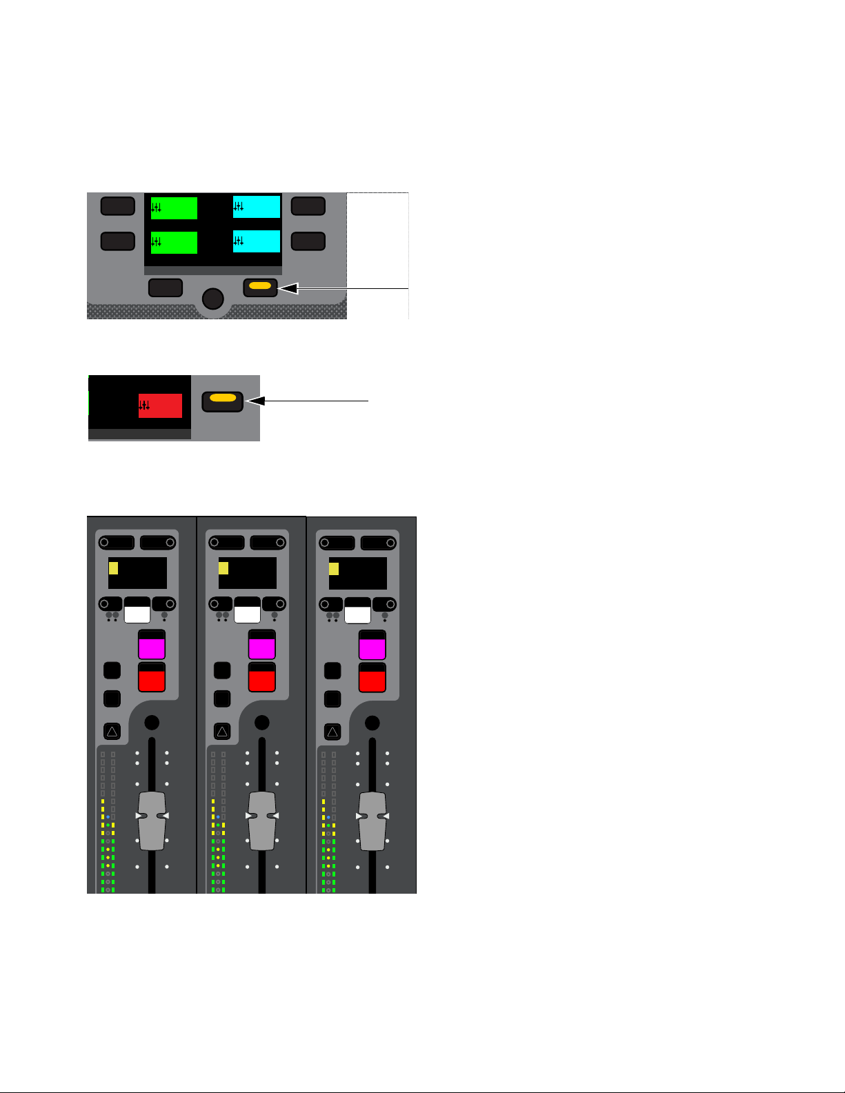
Working with Mains and VCAs 131
Adjusting Mains from the Channel Strips
You can adjust Mains using the channel strips by banking Mains to faders in Split Banking mode or Outputs Fader Bank mode.
To bank Mains in Split Banking Mode:
1 De-select a Fader Bank mode switch if one is enabled to enter Split Banking mode.
2 In the Left Soft Keys display, press the lit Next switch until you see Mains in the Soft Keys display
3 Press the Mains Soft Key so it lights.
Mains Left, Right and C/Mono are banked to the three leftmost faders on the center fader bank (under the MLM). You can access
Mains output processing controls as for other banked channels (as described in
Adjusting Channel Parameters).
To bank Mains Fader Bank mode:
1 Press the Outputs Fader Bank mode switch.
2 In the Left Soft Keys display, Press the Mains Soft Key so it lights.
Mains Left, Right, and C/Mono are banked to the three leftmost faders on the control surface.
Lit Next switch
Mains Soft Key
Mains banked to channel strips
Next
VCA 1-8
1-8
VCA 9-16
9-16
Ch 65-80
65-80
Ch 81-96
81-96
Next
Mains
Mns
10
5
0
6
12
Select
Solo
Y
X
Menu Safe
Mute
9
3
0
3
9
15
AS B
R
Right
0.0 dB
10
5
0
6
12
Select
Solo
Y
X
Menu Safe
Mute
9
3
0
3
9
15
AS B
L
Left
0.0 dB
10
5
0
6
12
Select
Solo
Y
X
Menu Safe
Mute
9
3
0
3
9
15
AS B
C
Center
0.0 dB
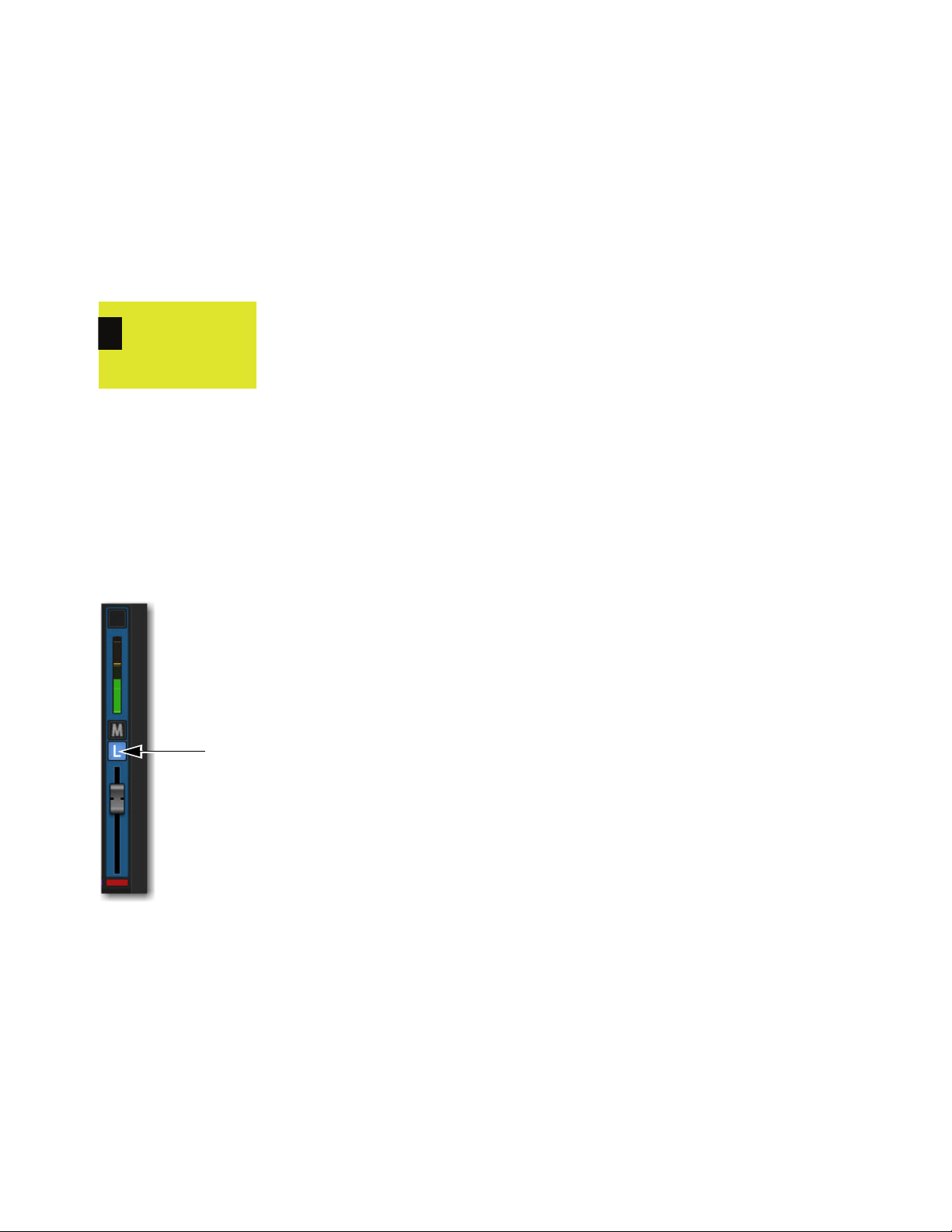
Working with Mains and VCAs 132
Using Mains in a User Layout
When you assign Mains L-R + C/Mono to a User Layout, a single fader for each of the three Mains outputs is assigned to the Layout
regardless of the Mains’ linked/unlinked state. When Mains are linked, adjusting the fader in the User Layout controls levels for
the linked Mains buses. You can target each individual Mains outputs on the control surface using the Attention switch, or on the
external screen using the Mains Focus button.
To target an individual Mains output in a User Layout on the control surface:
1 Assign the Mains to a User Layout (see
Assigning Channels to a User Layout).
2 Press the Layouts Fader Bank Mode switch. Mains L-R + C/Mono are assigned to a single fader.
3 To attention one of the Mains, press the channel strip Attention switch until the channel display shows the desired Mains output.
To target an individual Mains output in the User Layout on the external screen:
1 Select the Inputs or Outputs page, fader strip, select the Mains Focus button above the Mute button to cycle through each Mains
channel.
To attention an individual Mains output on the external screen:
1 Assign the Mains to a User Layout and bank the User Layout
2 On the User Layout Mains fader strip, select the Mains Focus button to cycle through each Mains channel. The currently targeted
Mains bus is indicated in the button (L, R, C/M).
A channel display showing Mains L targeted to the fader
Mains Focus button
0.0 dB
L
Mains

Working with Mains and VCAs 133
Linking/Unlinking Mains
By default, all three Main buses are linked in terms of level control and mute status. You can unlink any of the three Main buses
for discrete control of level and mute.
To unlink the Mains:
In the Outputs page, select the on-screen channel Link boxes for the Left, Right, and/or C/Mono fader strips so they are unlit.
Channel processing for the Mains Left-Right, such as built-in EQ, dynamics, and plug-ins, are always linked, regardless of
its linked/unlinked status.
Fader strip link boxes
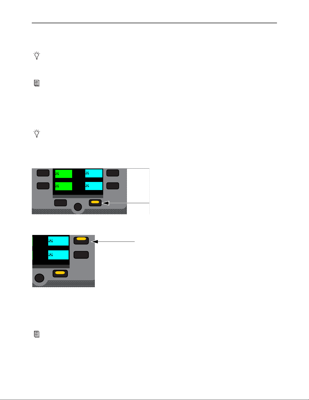
Working with Mains and VCAs 134
Working with VCAs
VCA controls emulate the operation of traditional Voltage Controlled Amplifiers (VCAs). Up to 32 VCAs are available. Any sys-
tem channels can be assigned to VCAs.
VCAs remotely control the fader gain of each channel assigned to the VCA fader, but do not change the position of the faders on
those channels. The accumulated gain of a channel assigned to one or more VCAs is limited to +12 dB.
VCAs can also be used to trim Aux send levels. See
VCAs Trim Aux Sends in Sends on Faders Mode.
Banking VCAs
You can bank VCAs to control surface faders in Split Banking mode and VCAs Fader Bank mode.
To bank VCAs in Split Banking Mode:
1 De-select a Fader Bank mode switch if one is enabled to enter Split Banking mode.
2 In the Left Soft Keys display, if necessary press the lit Next switch until you the VCAs you want to bank in the Soft Keys display
3 Press a VCAs Soft Key so it lights. The selected VCAs are banked to the faders on the center fader bank (under the MLM).
4 Do any of the following to adjust a VCA’s parameter:
• Adjust the fader to adjust VCA level.
• Press the channel strip Mute switch to implicitly mute member channels.
• Press a channel strip Solo switch to solo the VCA.
VCAs control level of the assigned channels only. They do not act as a summing output bus.
See
Assigning Channels Using Multi-Assign and Assign VCAs and Mute Groups from Channel Control Encoders
for instructions on assigning channels to VCAs.
Spill Mode for Outputs provides another way to bank channels assigned to VCAs.
Lit Next switch
VCA 9-16 Soft Key
For more information see
Explicit and Implicit Channel Mute with Mute Groups and VCAs.
Next
VCA 1-8
1-8
VCA 9-16
9-16
Ch 65-80
65-80
Ch 81-96
81-96
Next
VCA 1-8
1-8
VCA 9-16
9-16

Working with Mains and VCAs 135
To bank VCAs in Fader Bank mode:
1 Press the VCA Fader Bank mode switch so it lights.
VCAs 1–24 (for the S6L-24/24D) or VCAs 1–32 (for the S6L-32D) are banked to all the faders on the control surface.
2 To bank VCAs 25–32 on the S6L-24/24D, press the corresponding Soft Key.
– or –
• Use the Horizontal Banking switches to nudge channels left or right, as desired (see
Banking Horizontally (Nudging Chan-
nels).
VCA Members on MTS/CTM Meters View
VCA members are shown in Meters view for VCAs.
If the VCA has 22 or more member channels you can scroll the list by swiping up and down.
Tapping a Mix tile (below each VCA/list) targets those members to the CKM. The currently targeted Mix tile is outlined in orange.
VCAs in Meters view
Members
Mix tiles

Working with Mains and VCAs 136
Channel Strips Show VCA Contribution
The effective gain of any channel is equal to the combination of its individual channel fader, plus any (all) VCA level changes that
affect that channel.
Input and output channels display the net effect of VCA level (effective gain) on-screen. This lets you keep track of what all cur-
rently assigned VCAs are doing to channels and buses at all times.
On-Screen VCA Indication
VENUE displays effective gain as a second, red “ghost” fader caps below the faders of channels that are currently assigned to one
or more VCAs.
The opacity of the ghost caps vary with the actual VCA levels:
• Lighter caps indicate smaller amounts of VCA contribution.
• Brighter caps indicate larger amounts of VCA contribution.
Turning Channel VCA Indication On and Off
By default, channel VCA indication is on. You can turn off VCA indication on the Options > Interaction page of the external
screen.
To turn channel VCA indication off or on:
1 On the external screen, go to Options > Interaction.
2 In the Fader Configuration section, select or de-select Show VCA Contribution as desired.
VCA contribution shown in the on-screen fader displays
Effective
Channel levels
gain (VCAs)
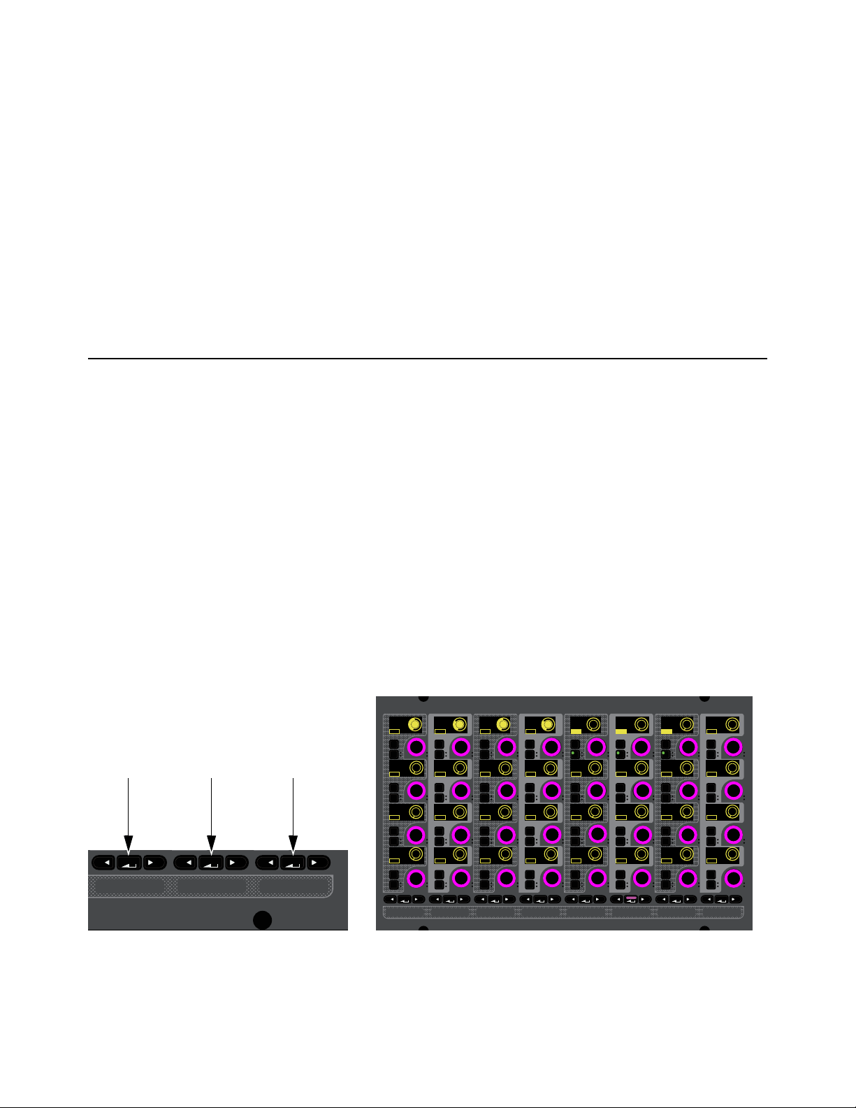
Working with Aux Sends 137
Working with Aux Sends
This chapter covers how to work with Aux Sends and covers the following:
•
Adjusting Aux Sends in Channel Control Mode
• Adjusting Aux Sends in Channel Strip Mode
• Adjusting Aux Sends on Faders (Sends on Faders Mode)
• VCAs Trim Aux Sends in Sends on Faders Mode
• Adjusting Aux Sends on the External Screen
• Classifying Auxes for Snapshots
Adjusting Aux Sends in Channel Control Mode
When accessing Aux Sends in Channel Control mode, the number of available Aux Sends, and the Mix switch or touch zone used
to spill the sends to the CKM encoders, depends on the overall Mix Bus configuration. See Configuring Mix Buses.
In Channel Control mode, Aux Sends are spilled to CKM encoders sequentially from left to right, and top to bottom. After spilling
Aux Sends, you can toggle the sends on/off, adjust send levels, and toggle sends pre-/post-fader using the encoders. You can set
the Aux send pre-fader pickoff point on a per-channel basis (see
Selecting Aux Pre-Fader Pickoff Points).
You can also access Aux Sends 1–4 in Channel Strip mode (see
Adjusting Aux Sends in Channel Strip Mode).
To spill Aux Sends using the MIX Channel Control Function switches:
1 Bank the desired channels.
2 Select one or more channels.
3 Press a MIX switch to spill the following Aux Sends to the encoders on the associated CKM, as available:
•The left MIX switch spills Aux Sends 1–32.
•The center MIX switch spills Aux Sends 33–64.
• The right MIX switch spills Aux Sends 65-96.
MIX Channel Control Function switches (left) and the Aux Sends 1–32 spilled to the encoders (shown at right)
MIXMIXMIX
In
Sel
In
Sel
In
Sel
In
Sel
In
Sel
In
Sel
MIXMIXMIXPLUG-INSDYNAMICSEQINPUTCHANNEL
In
Sel
In
Sel
In
Sel
In
Sel
In
Sel
In
Sel
In
Sel
In
Sel
In
Sel
In
Sel
In
Sel
In
Sel
In
Sel
In
Sel
In
Sel
In
Sel
In
Sel
In
Sel
In
Sel
In
Sel
In
Sel
In
Sel
In
Sel
In
Sel
In
Sel
In
Sel
In
Sel
In
Sel
In
Sel
In
Sel
In
Sel
In
Sel
Aux 1 Aux 3 Aux 4
-10.0 dB -20.0 dB -10.0 dB
-20.0 dB
Aux 5
-INF
Aux 6
-INF
Aux 7
-INF
Aux 8
-INF
Aux 13
-INF
Aux 14
-INF
Aux 15
-INF
Aux 16
-INF
Aux 9
-INF
Aux 10
-INF
Aux 11
-INF
Aux12
-INF
Aux 17
-INF
Aux 18
-INF
Aux 19
-INF
Aux 20
-INF
Aux 25
-INF
Aux 26
-INF
Aux 27
-INF
Aux 28
-INF
Aux 21
-INF
Aux 22
-INF
Aux 23
-INF
Aux 24
-INF
Aux 29
-INF
Aux 30
-INF
Aux 31
-INF
Aux 32
-INF
Aux 2
Pre
Pre
Pre
Pre
Pre
Pre
Pre
Pre
Pre
Pre
Pre
Pre
Pre
Pre
Pre
Pre
Pre
Pre
Pre
Pre
Pre
Pre
Pre
Pre
Pre
Pre
Pre
Pre
Pre
Pre
Pre
Pre
ONONON
ONONON
ONONON
ONONON
ONONON ON
ONONON ON
ONONON ON
ON ON ONON
ON
ON
ON
ON

Working with Aux Sends 138
To spill Aux Sends using the CTM in Meters view:
Touch the Aux Sends touch zone on the associated CTM. The Aux Sends that are spilled are indicated by the channel number
range at the top of the touch zone.
To spill Aux Sends using the CTM in Channel view:
1 If necessary, in Meters view touch the Meters for the channel you want to access in Channel view.
2 Touch one of the three Aux Sends touch zones in the Aux Sends section on the associated CTM. The active zone is bordered in
red. Each zone spills the following Aux Sends to the CKM encoders, as available:
• Zone 1 (topmost zone) spills Aux Sends 1–32.
• Zone 2 (middle zone) spills Aux Sends 33–64.
• Zone 3 (bottom zone) spills Aux Sends 65-96.
To toggle an Aux Send on/off:
Press the encoder under the display showing the Aux Send you want to adjust, such as Aux 1.
On is shown in the encoder display when the send is on. Off is shown when the send is off. On-screen, the thermometer-style
level indicator for each Aux Send lights when Aux Send is on, and is dimmed when off.
CTM Meters view (left) and a closeup of the Aux Send touch zone
Aux Sends touch zones in CTM Channel view (80 Aux configuration shown)
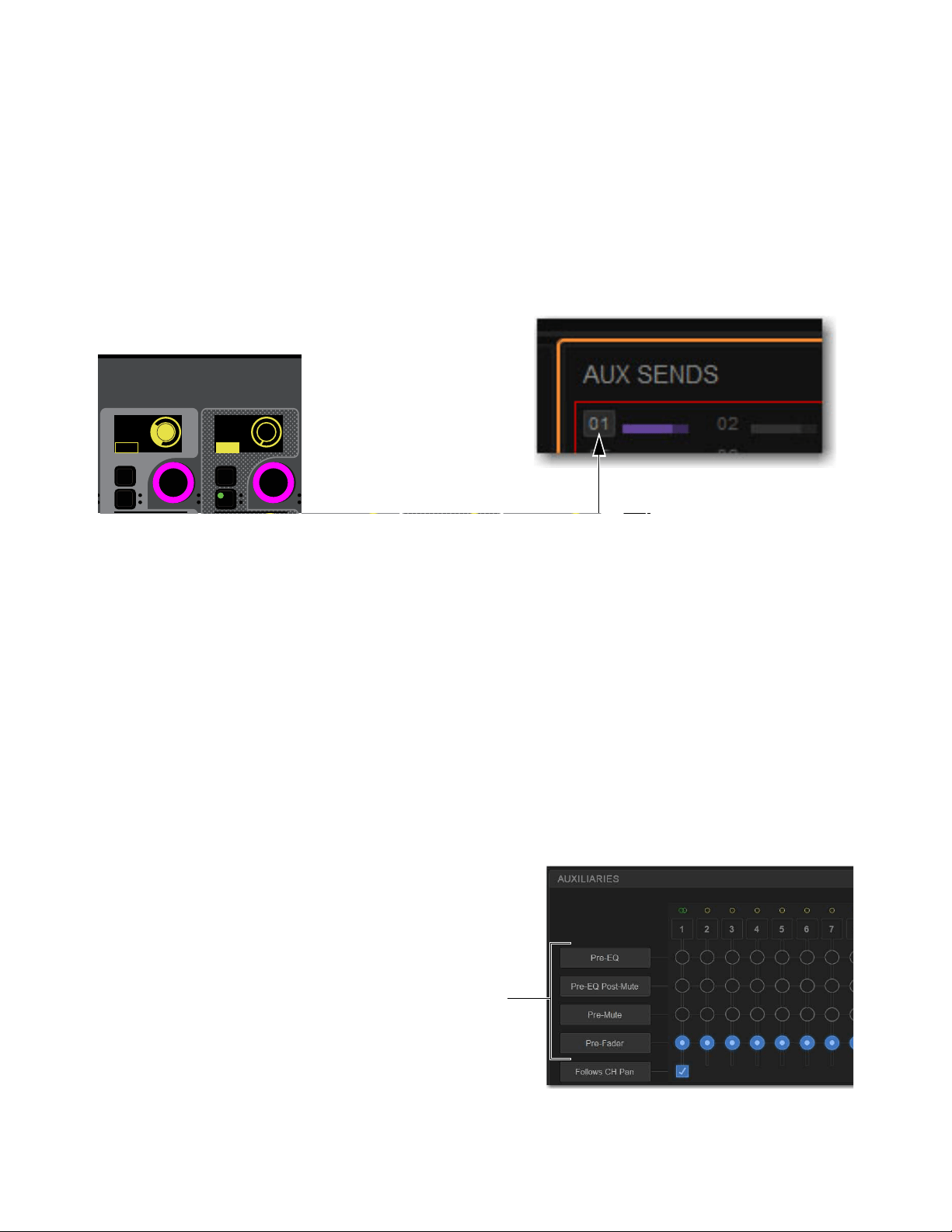
Working with Aux Sends 139
To adjust Aux Send level:
Rotate the encoder under the display showing the desired Aux Send.
Send level is shown in the corresponding encoder display. On-screen, thermometer-style level indicators in the Aux Sends zones
show Aux Send level.
To toggle an Aux Send pre-/post-fader:
Press the encoder In switch under the display showing the desired Aux Send. The following elements indicate that an Aux Send
is pre-fader:
• The corresponding encoder
In switch lights.
• Pre or Post is shown in the corresponding encoder display.
• On-screen, a border appears around the channel numbers.
.
Selecting Aux Pre-Fader Pickoff Points
Each Aux Send can be set as pre- or post-fader. You can specify the pre-fader pickoff point for Aux buses.
Pre-Fader pickoff points are set for each bus independently. If any buses are stereo, the pickoff point is set for the stereo pair. The
following pre-fader pickoff points for Aux buses are available:
Pre-EQ
Post-HPF/LPF and pre-EQ, Dynamics and Channel Inserts, pre-Mute, and pre-Fader. The Aux send is not affected by the
channel mute.
Pre-EQ Post-Mute
Post-HPF/LPF and pre-EQ, Dynamics and Channel Inserts, post-Mute, and pre-Fader. The Aux send is af-
fected by the channel mute.
Pre-Mute
Post-HPF/LPF, post-EQ, Dynamics, and Channel Inserts, pre-Mute, and pre-Fader. The Aux send is not affected by the
channel mute.
Pre-Fader
Post-HPF/LPF, post-EQ, Dynamics, and Channel Inserts, post-Mute, and pre-Fader. The Aux send is affected by the
channel mute.
To set the pre pickoff point for an Aux send:
1 On the external screen, go to Options > Buses.
2 Select an Aux Select Button button to access those Auxes in the
grid.
3 In the Auxiliaries section, select the Pre-EQ, Pre-EQ Post Mute,
Pre-Mute, or Pre-Fader button so it lights.
CKM encoders showing the various Aux Send states (left) and indication of a pre-fader Aux on the CTM (right)
In
Sel
In
Sel
In
Sel
In
Sel
In
Sel
Aux 4
-20.0 dB
Aux 5
-INF
Aux 6
-INF
Aux 7
-INF
Aux 8
-INF
Pre Pre Pre Pre Pre
ONONON
ON
ON
Aux bus pickoff points

Working with Aux Sends 140
Adjusting Stereo Sends in Channel Control Mode
You can combine any two Aux outputs into a single stereo Aux output using Make Stereo (see Make Selected Mono Strips Ste-
reo/Make Selected Stereo Strip Mono). With stereo Auxes, you can pan send signals across the stereo pair, or panning can fol-
low channel pan (enabled per-Aux on the Options > Buses page of the external software).
On CKM encoders, stereo Aux Send controls are combined into one encoder, which controls both level and pan.
To adjust a stereo Aux Send in Channel Control mode:
1 Bank to and select the desired channel.
2 Press the appropriate MIX Channel Control Function switch or CTM touch zone to access the
desired stereo Aux Send.
The stereo send is available on a single encoder.
3 To adjust stereo Aux Send level, rotate the encoder.
4 To adjust send pan, do the following:
• Press the corresponding encoder Sel switch so it lights. Send pan is now targeted to the
corresponding encoder, the color in the corresponding encoder display inverts, and P
<Aux number/name> and pan value appears in the display.
• Rotate the encoder to adjust send pan.
Adjusting Aux Sends in Channel Strip Mode
You can control Aux Sends 1–4 on the CKMs in Channel Strip Mode.
To adjust Aux Sends in Channel Strip mode:
1 Bank the desired input or output channels.
2 Do either of the following to enable Channel Strip mode:
• Press a lit Select switch to de-select it and enable Channel Strip mode on the associated CKM.
• Press Select Clear to de-select all channels on the control surface and enable Channel Strip mode on all CKMs.
3 Navigate to the Aux Send Channel Strip mode parameter bank by pressing lit Parameter Bank switches, as available, until the
encoders appear purple.
Aux Sends 1–4 appear on the fifth page of Channel Strip mode parameters.
To toggle an Aux Send on/off:
Press the encoder under the display showing the Aux Send you want to adjust, such as Aux 1.
On is shown in the encoder display when the send is on. Off is shown when the send is off.
To adjust Aux Send level:
Rotate the encoder under the display showing the desired Aux Send.
To toggle an Aux Send pre-/post-fader:
Press the encoder In switch under the display showing the desired Aux Send. The following control and on-screen elements in-
dicate that an Aux Send is pre-fader:
To adjust stereo send pan:
1 Press the corresponding encoder Sel switch so it lights. Send pan is now targeted to the corresponding encoder and P <Aux num-
ber/name> and pan value appears in the corresponding encoder display.
2 Rotate the encoder to adjust send pan.
When two Aux outputs are made stereo, no blank strips are created or inserted, and channels in the layout in that bank are
shuffled to the left, including the corresponding Aux Sends.
In
Sel
P. Aux 1
<0>
On
Pan
Pre
CKM encoder showing Aux Send
pan targeted to the encoder
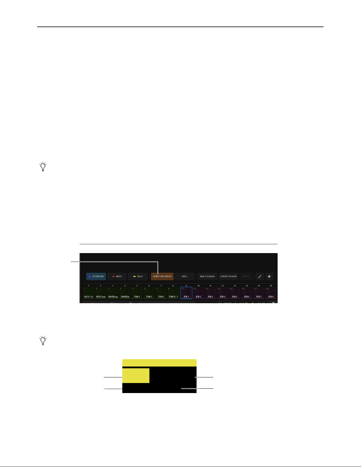
Working with Aux Sends 141
Adjusting Aux Sends on Faders (Sends on Faders Mode)
The S6L system provides a Sends on Faders mode to facilitate monitor mixing workflows. Sends on Faders mode is available in
two forms, Direct, and Sends on Faders Follows AFL.
Direct Sends on Faders
Enabling the Sends on Faders button in the Universe View on the MTS lets you select any Aux to assign
its members’ sends (channels assigned to/feeding that Aux) to the faders, without soloing the Aux. Unlike spilling an Aux, Direct
Sends on Faders does not bank or change input strips.
Sends on Faders Follows AFL
In Sends on Faders Follows AFL mode, soloing an Aux output simultaneously assigns its sends to
the faders and routes the Aux output’s signal to the Monitor bus. This lets you simultaneously monitor the Aux output mix and ad-
just its send levels using the faders with the press of a switch or the touch of an on-screen button. You must enable
Sends on Fad-
ers Follows AFL functionality on the Options > Busses page of the external screen.
Sends on Faders mode only affects input channels. It does affect all input channels, however. If no input channels are banked when
Sends on Faders is activated, all “hidden” input channels also enter Sends on Faders mode. When banking to other input channels,
Sends on Fader mode remains enabled for the newly banked channels.
Associated CKMs remain unaffected in Sends on Faders Follows AFL mode, so all Channel Control or Channel Strip mode func-
tions for the banked channels remain freely available.
Using Direct Sends on Faders Mode
To use Direct Sends on Faders from the MTS:
1 Bank input channels to the faders in any fader banking mode, or bank a User Layout that includes input channels.
You can activate Sends on Faders in Split Banking mode, and Inputs and Layouts Fader Bank mode.
2 On the MTS, touch Universe, then touch Auxes to show Aux channel tiles.
3 On the MTS, tap to enable the Sends on Faders Channel Tile Function button.
4 Tap the Channel Tile for the Aux output whose sends you want to adjust.
The channel displays show SOF and the number or name of the Aux output.
5 To adjust the level of a channel assigned to the current Aux, adjust its fader or SOF knob (if the Aux is mono) on the associated
CKM.
Spill Mode for Outputs provides another way to bank channels assigned to Auxes.
Sends on Faders button enabled in Universe > Auxes
See also
Position Safe When Spilling.
Channel display for an input channel in SOF mode
<name>
Aux 1
SOF
CH1
S1 AD1
Channel number Channel name
Aux
Hardware input
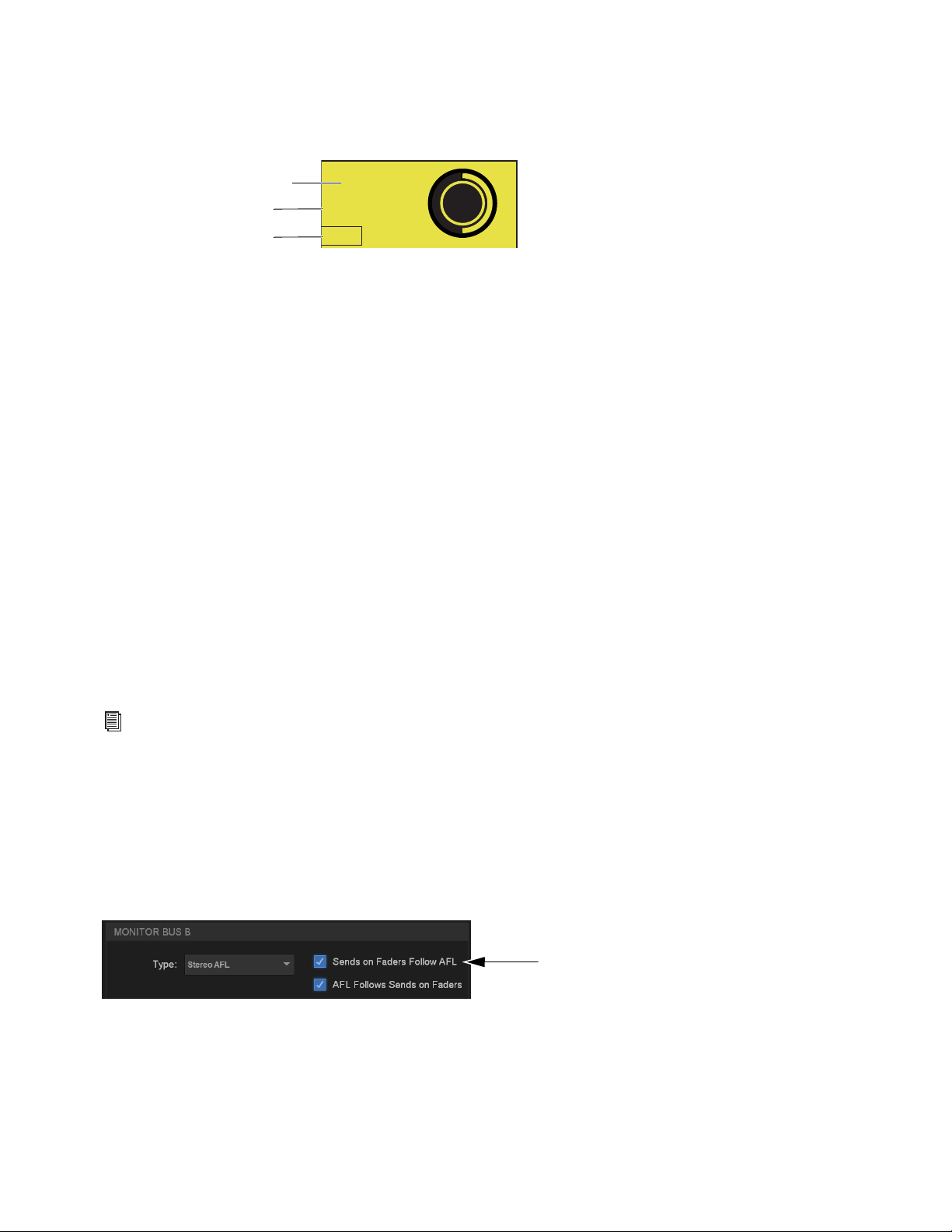
Working with Aux Sends 142
6 To adjust other Send parameters do the following using the SOF controls in row 4 on the associated CKM:
• To enable or disable channel assignment to the current Aux, press the CKM knob.
• To toggle the Aux between Pre and Post, press the knob
In switch (when the In switch LED is lit it indicates Pre-fader).
To access the sends of another Aux output do any of the following:
• On the MTS, tap another Aux output’s Channel Tile to spill those Aux Sends to the faders.
• Press the Attention key on any other Aux strip.
• Attention another Aux using the external screen.
To exit Sends on Faders, do any of the following:
• On the MTS, tap to disable the Sends on Faders Channel Tile Function button.
• On the MLM, press the flashing Cancel switch.
• On the external screen, tap Exit Sends on Faders in the alert dialog.
Using Sends on Faders Follows AFL Mode
Sends on Faders Follow AFL mode lets you simultaneously monitor the Aux output mix and adjust its send levels using the faders
with the press of a switch or the touch of on-screen button.
Sends on Faders Follow AFL must be enabled on each desired Monitor bus independently. Make sure to enable Sends on Faders
Follows AFL on the Monitor bus that your input channels are currently routed to (assuming you want all input channels to be sub-
ject to Sends on Faders Follow AFL).
For example, you can route some of your input channels to Monitor bus A with Sends on Faders Follow AFL disabled, and route
other channels to the other Monitor bus B with Sends on Faders Follows AFL enabled. You can then route each Monitor bus to a
discrete hardware or headphone output.
If any input channels are targeted to both Monitor buses, then enabling
Sends on Faders Follows AFL on either Monitor bus re-
sults in Sends on Faders behavior for that channel.
Enabling Sends on Faders Follow AFL
To enable Sends on Faders:
1 Go to the Options > Buses page of the external screen.
2 Under Monitor Bus A or Monitor Bus B, select Sends on Faders Follow AFL so it is checked.
Channel display for an input channel in SOF mode
For more information on configuring your Monitor buses, see
Configuring the Monitor Buses and Solo Options.
Sends on Faders enabled for Monitor Bus A
Aux 1
-10.0 dB
Pre
On
Aux current SoF’d
Pre/Post indicator
Aux send level
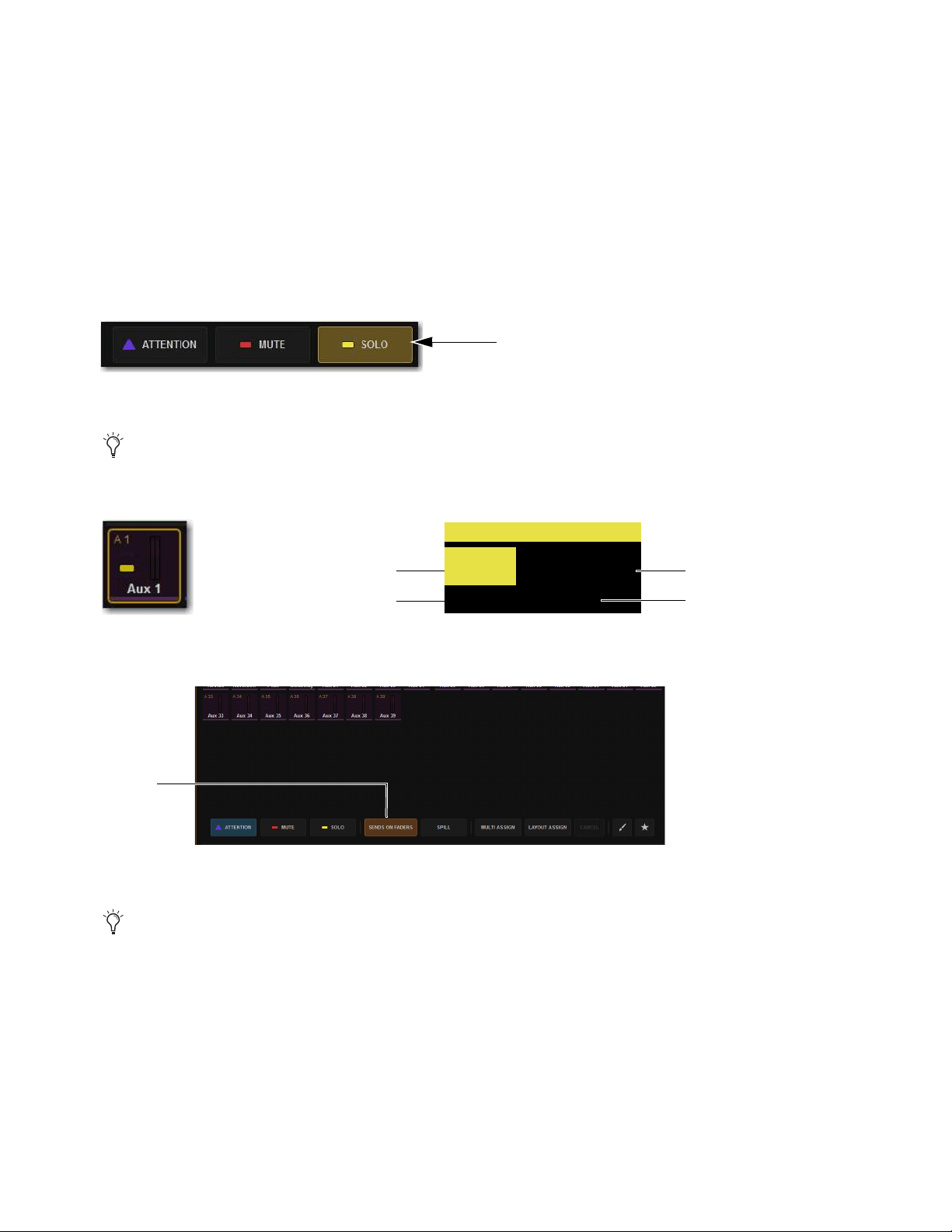
Working with Aux Sends 143
Accessing Aux Sends in Sends on Faders Follow AFL Mode
After enabling Sends on Faders Follow AFL, you can bank the Aux sends to faders by soloing an Aux output. You can activate
Sends on Faders Follow AFL in Split Banking mode, and Inputs and Layouts Fader Bank mode. You can bank to other channels
while in Sends on Faders Follow AFL mode, but you must stay within the current banking mode (Split Banking mode or Fader
Banking mode) to remain in Sends on Faders Follow AFL mode. You can also access other sends for other Aux outputs while Sends
on Faders Follow AFL is active.
To adjust Aux Sends on Faders:
1 Bank input channels to the faders in any fader banking mode, or bank a User Layout that includes input channels.
2 On the MTS, touch Universe, then touch Auxes to show Aux channel tiles.
3 Touch the Solo Channel Tile Function button so it lights.
4 Tap the Channel Tile for the Aux output whose sends you want to adjust.
The channel displays show SOF and the number or name of the Aux output.
On the Universe view on the MTS, the
Sends on Faders button lights.
5 Adjust the faders to adjust send levels.
To access the sends of another Aux output:
• Solo another Aux output to spill those Aux Sends to the faders.
• Tap a different Aux tile on the MTS.
To exit Sends on Faders, do any of the following:
• Un-solo the currently soloed Aux output.
• On the MLM, press the flashing Cancel switch.
• On the external screen, tap Exit Sends on Faders in the alert dialog.
Solo Channel Tile function switch
You can also solo Aux outputs from the channel strips when Auxes are banked to the center fader bank in Split Banking mode,
or by using the Solo button for the Aux output on the Outputs page of the external screen.
A Channel Tile showing a soloed Aux (left) and a channel display indicating Sends on Faders mode (right
Indication of Sends on Faders enabled
See also
Position Safe When Spilling.
<name>
Aux 1
SOF
CH1
S1 AD1
Channel number Channel name
Aux
Hardware input
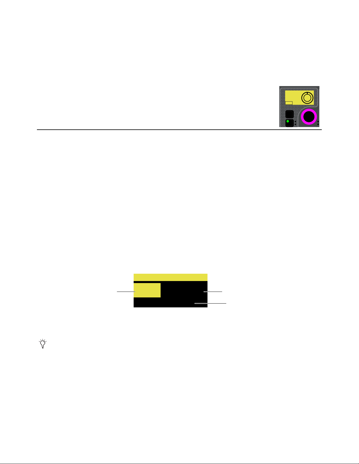
Working with Aux Sends 144
Adjusting Stereo Sends in Sends on Faders Modes
To adjust Aux Send pan in Sends on Faders mode, the fader bank from which you are adjusting pan must be in Channel Strip mode.
To adjust stereo sends in Sends on Faders modes:
1 Bank to the desired input channels.
2 Use Direct Sends on Faders, or solo a stereo Aux output while Sends on Faders Follows AFL is enabled, to enter Sends on Fad-
ers mode.
Aux Send pan for each banked channel is assigned to the bottom row of encoders in Channel Strip mode,
and
P <Aux number/name> appears in the encoder displays.
3 Rotate the knob to adjust send pan for the corresponding channel.
• Press the send pan encoder In switch to toggle that send pre-/post fader.
VCAs Trim Aux Sends in Sends on Faders Mode
The VCAs Trim Aux Sends in SOF setting in Options > Interaction lets you use VCAs to quickly trim multiple Aux Send levels
(such as all drums, or all background vocals) while in Sends on Faders mode.
To use VCAs Trim Aux Sends in SOF:
1 Go to Options > Interaction and make sure VCAs Trim Aux Sends in SOF is enabled (its default setting).
2 Assign channels to Auxes and set their preliminary send levels.
3 Make sure you have assigned channels to VCAs.
4 Place an Aux into Sends on Faders mode. (For instructions, see the VENUE S6L System Guide.pdf)
The Input channel displays show SOF and the number or name of the Aux output.
5 Bank VCAs to fader strips.
• To access 8 Aux VCAs at a time, press a VCA soft key in the left bank of MLM Soft Keys.
• To access Aux VCAs across all fader strips, press the VCAs banking switch on the MLM.
The corresponding (VCA) fader strip displays show SOF VCA, the number and name of the VCA, and the number or name of
the Aux being trimmed.
Faders on SOF VCAs locate to 0 (unity). Trims made with SOF VCAs directly change the corresponding Aux send levels
(changes are not stored in the Show file). After exiting and re-entering SOF VCA mode, VCA faders again locate to 0 (unity).
6 Adjust a VCA to trim the corresponding Aux Send levels.
SOF VCA mode is designed to make small trim adjustments. Note that any offsets between channel Aux send levels can be lost
if the SOF VCA is lowered or raised to extremes.
VCA display in Aux VCA mode
When VCAs are in SOF VCA mode the blue “0” LED does not light, to indicate that SOF VCA mode is enabled.
In
Sel
P. Aux 1
<0>
On
Pre
<name>
Aux 8
SOF VCA
VCA1
VCA number VCA name
Aux
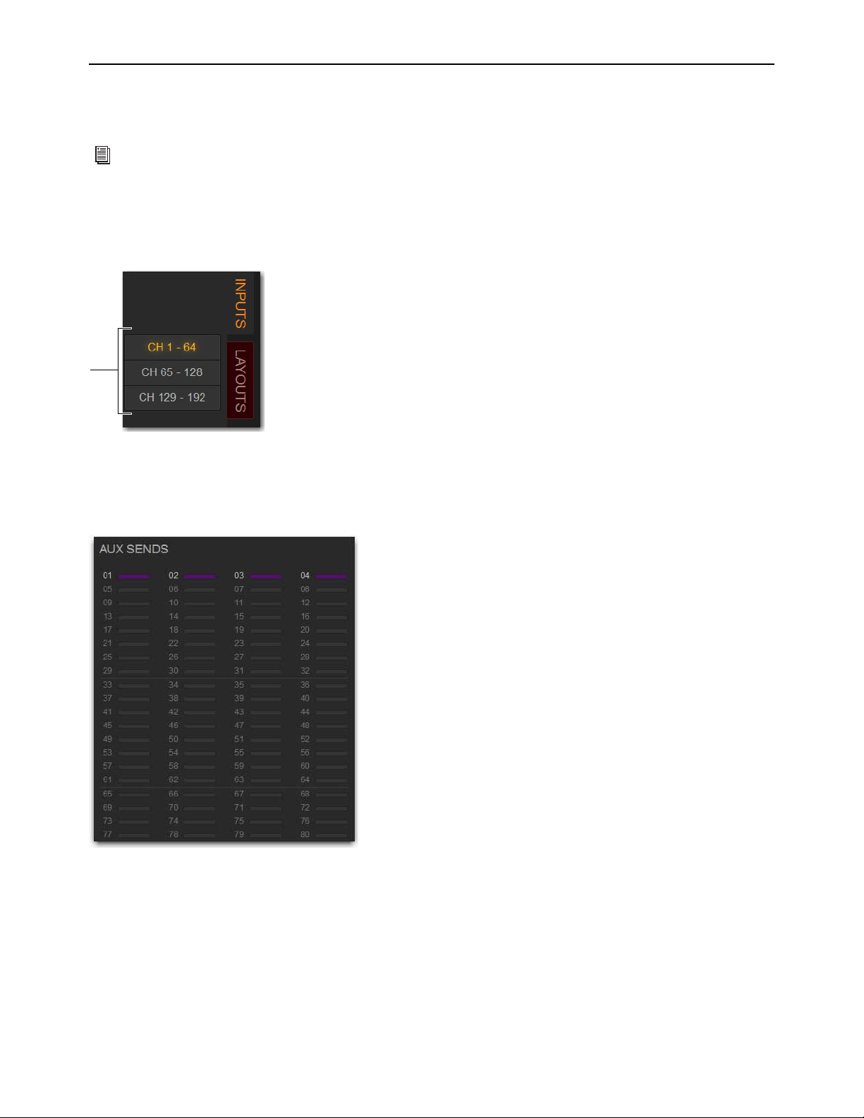
Working with Aux Sends 145
Adjusting Aux Sends on the External Screen
You can toggle individual sends on/off and pre-/post-fader, as well as view send level and pan (for stereo sends) for the attentioned
channel on the Inputs page of the external software.
To adjust Aux Sends on the external screen:
1 Go to the Inputs page.
2 Select the Inputs tab, then select the bank of input channels you want to access using the Input Channel Type buttons.
3 Attention an input channel.
4 To toggle an Aux Send on/off, select the thermometer-style indicator. When the indicator lights, the send is on. The indicator
lights in the color assigned to that Aux output.
For more information on working with channels on the external screen, see
Adjusting Parameters on the External
Screen.
Input Channel Type buttons
Inputs page Aux Sends section showing Auxes 1–4 enabled for the attentioned channel(s)

Working with Aux Sends 146
Expanded Aux Sends View on the External Screen
The Inputs page provides an expanded Aux Sends view that provides touch access to all Aux parameters. Auxes in Expanded Aux
view can be sorted, and the display filtered by color, favorites, and In status.
To use Expanded Aux view (refer to the figures):
1 Navigate the external screen to the Inputs page.
2 Tap in the Auxes view within the range of 16 Auxes you want to show in Ex-
panded view. Or tap the Expand icon in the upper right corner of the Aux
section to show the previously Expanded Aux view.
Expanded Aux view displays Auxes in banks of 16. All Aux parameters can
be adjusted on the external screen.
3 To show a different bank of Auxes, select a tab (such as 17-32).
4 To control how and which Auxes are displayed, use the Filter buttons (123 or
A–Z), color blocks, star, or IN (to show only Auxes that are on/enabled).
5 To make or change assignment to Mains, use the L-R and C/MONO buttons.
6 To access Reset and Channel Control Aux commands, tap the triangle above each Aux Level block and choose a command
from the pop-up menu and sub-menu.
7 To close the Expanded Aux view, tap the Expand icon (“2” in the figure).
Classifying Auxes for Snapshots
You can classify Aux Sends as monitor sends (“Mon”) or as effects sends (“FX”) for the purposes of scoping and safing each type
separately in snapshots.
Classifying Aux Sends. In addition, you can use the User Aux Scope tab to scope Auxes individually.
Expanded Aux view in the Inputs page
Aux Sends Touch zones in the Inputs page
2
1
2
4
3
5
6

Matrix Mixers 147
Matrix Mixers
This chapter covers using the S6L system’s Matrix Mixers, and includes the following topics:
Matrix Mixers Overview
The S6L system provides 16 (E6L-144) or 24 (E6L-192) mono Matrix Mixers for setting up alternate mixes, fill and delay feeds,
and cue, monitor or press mixes.
Each of the available Matrix Mixers can receive up to 24 discrete input sources. Input sources can be any combination of input
channels, Auxes, Groups, Monitor A or Monitor B, or Mains buses. Each Matrix Mixer has a mono output, but you can combine
two Matrix Mixers into one stereo Matrix output using the Make Stereo command (see
Make Selected Mono Strips Stereo/Make
Selected Stereo Strip Mono).
• Matrix Mixers Overview
• Assigning Input Sources to Matrix Mixers
• Adjusting Matrix Mixer Input Controls
• Delay Compensation with Matrix Mixers
• Adjusting Matrix Mixer Output Controls
• Snapshot Data and Parameters for Matrix Mixers
A Matrix Mixer on the Outputs page of the external screen
1 – Matrix Mixer Tab
2 – Matrix Inputs
3 – Matrix Input Source Selectors
4 – Matrix Input Controls
5 – Matrix Mixer Reset/Clear Selector
6 – Matrix Mixer Output Fader Strips
7 – Matrix Mixer Output Controls
7
4
5
6
1
2
3
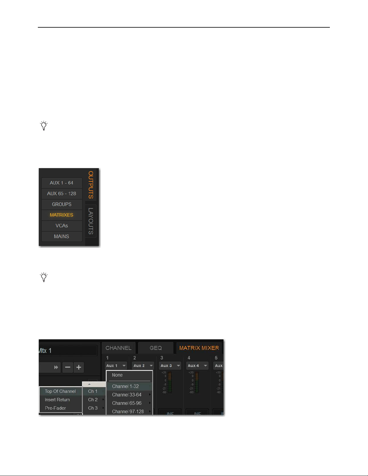
Matrix Mixers 148
Assigning Input Sources to Matrix Mixers
Each Matrix Mixer can receive up to 24 discrete input sources. You can assign any combination of input channels, Auxes, Groups
or Mains buses Each Matrix Mixer has a mono output, but outputs can be linked to form a stereo pair. A variety of pickoff points
are available when assigning Matrix input sources. Matrix input source assignments are made using the external screen.
Pickoffs for each input are selected when you select the input source. Matrix Mixers provide the following pickoff points for source
channels:
Input Channels
Top of channel, Insert Return, or Pre-Fader Post-Mute
Output Channels
Pre-Fader Pre-Mute, or Post- Fader
Monitor Busses
Pre-Fader Pre-Mute, or Post-Fader
To assign input sources to a Matrix mixer:
1 On the external screen, go to the Outputs page.
2 Select the Outputs tab, then select the Matrixes Channel Type button.
3 Attention the desired Matrix Mixer(s).
4 Select the Input Source selector at the top of each Matrix channel
5 For each input source, choose the following:
• Choose the desired input source.
• Choose the desired channel.
• Choose from the available pickoff points.
While either Monitor A or B are assigned to any Matrix, Solo on that Matrix is unavailable.
Output Channel Type buttons
You can use Multi-Select to attention multiple Matrix Mixers and apply the same input source to all selected Matrixes.
Matrix Mixer input source menu showing input sources, channels, and pickoff points
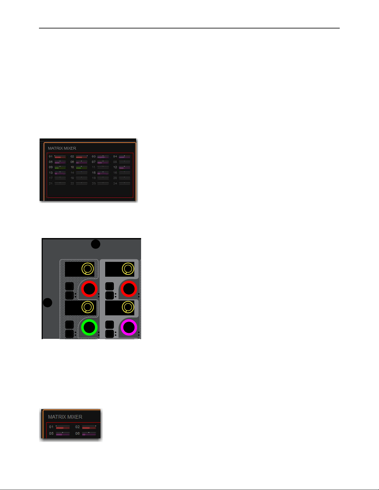
Matrix Mixers 149
Adjusting Matrix Mixer Input Controls
You can adjust Matrix Mixer input levels using the CKM in Channel Control mode, or the external screen.
Adjusting Matrix Mixer Input Level
To adjust Matrix Mixers input levels:
1 Bank Matrixes to the faders.
2 Select a banked Matrix.
3 Press any MIX Channel Control Function switch on the associated CKM.
– or –
• Touch the Matrix Mixer touch zone on the associated CTM in Meters or Channel view.
The selected Matrix Mixer’s input controls are spilled to CKM encoders. The source for each Matrix Input is shown in the cor-
responding encoder display. The encoders for the different inputs are colored according to their global color-coding setting.
4 To toggle an input on/off, Press the encoder under the display showing the Matrix Mixer input you want to adjust.
The corresponding encoder In switch lights green when the input is on. On the CTM in Channel view, and the MTS in Meters
and Channel views, thermometer-style level indicators light when the input is on, and is dimmed when off.
5 To adjust input level, rotate the encoder under the display showing the desired Aux Send.
Input level is shown in the corresponding encoder display, on the CTM in Channel view, and on the MTS in Meters and Channel
views.
Matrix Mixer touch zone on the CTM in Channel view
Matrix Mixer input sources on the CKM encoders
Matrix Mixer input levels shown on the CTM in Channel view
In
Sel
In
Sel
In
Sel
In
Sel
Left
-Inf
Right
-Inf
Ch 9
-Inf
Aux 10
-Inf
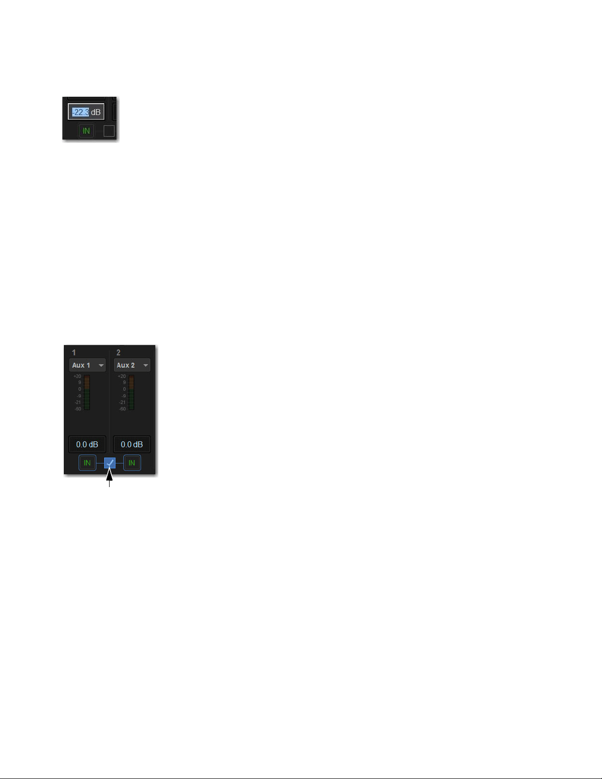
Matrix Mixers 150
To enter an input levels on the external screen:
1 On the Matrix Mixer tab, touch the input level field.
2 Type in an amount using the keyboard, and then press Enter.
Linking and Unlinking Adjacent Matrix Inputs
Adjacent inputs to Matrix mixers can be linked or unlinked on a per input pair basis. Link status can be specified on a per Matrix
basis (for example, inputs 1 and 2 can be linked for Matrix 1, but unlinked for Matrix 2). This gives you the ability to control inputs
as either a stereo-linked pair or as independent mono inputs.
• When linked, level and source on/off controls are linked.
• When unlinked, discrete level and on/off controls affect each individual channel.
To link or unlink inputs to Matrix mixers:
1 On the external screen, go to the Outputs page.
2 Select the Outputs tab, then select the Matrixes Channel Type button.
3 Select the checkboxes below any adjacent inputs to link or unlink them. A check mark in the checkbox indicates a linked input
source; an empty checkbox indicates unlinked sources.
Matrix Mixer Input Pan
Matrix mixer input pan controls adjust the panning of each Matrix mixer input across the stereo outputs of a stereo Matrix Mixer.
To control Matrix send pan from the Global Control encoders:
1 Assign the Matrix mixer input source to Global Control for the stereo Matrix you want adjust.
2 Press the encoder Sel switch to assign send pan control to the encoder.
3 Adjust the encoder to adjust pan.
• Rotate to the left to pan the input source to the left (odd-numbered) Matrix mixer.
• Rotate to the right to pan the input source to the right (even-numbered) Matrix Mixer.
Entering a Matrix Mixer input level using a keyboard
Matrix link button
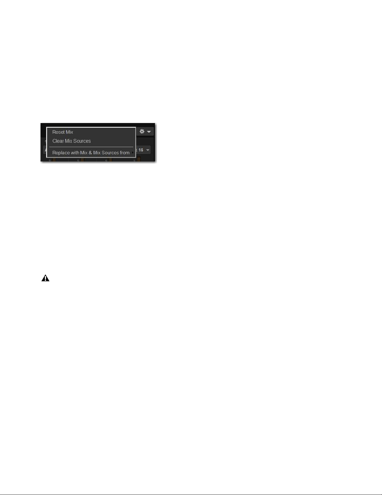
Matrix Mixers 151
Resetting Matrix Mixer Input Paramters
You can reset level, pan and stereo link settings for any matrix mixer. Input source assignments persist.
To reset a Matrix mixer parameter to its default value:
1 Attention one or more Matrix mixers you want to change.
2 Touch-and-hold (right-click) the encoder on-screen and choose Reset.
To reset all Matrix mixer parameters to their default values:
1 Attention one or more Matrix mixers you want to change.
2 Select the Matrix Mixer Reset/Clear Selector at the top right of the Matrix Mixer, and choose Reset Mix.
Clearing Matrix Mixer Input Assignments
You can clear mixer input assignments to quickly set all the input sources to None.
To clear Matrix input assignments:
1 Attention one or more Matrix mixers you want to change.
2 Select the Matrix Mixer Reset/Clear Selector and choose Clear Mix Sources.
Copying Matrix Mixer Input Settings
You can copy mixer settings from one Matrix mixer to another mixer of the same type. This lets you quickly duplicate monitor
mixes or other signal feeds.
To copy settings between mixers:
1 Attention the Matrix mixer that you want to be the destination of the copied settings so that it is displayed on-screen.
2 Select the Matrix Mixer Reset/Clear Selector and choose Replace With Mix and Mix Sources From.
3 Choose the Mtx (Matrix mixer) from the sub-menu whose settings you want to copy to the current Matrix Mixer.
Matrix Mixer Reset/Clear menu
Copying mixer settings overwrites all the settings on the destination mixer.
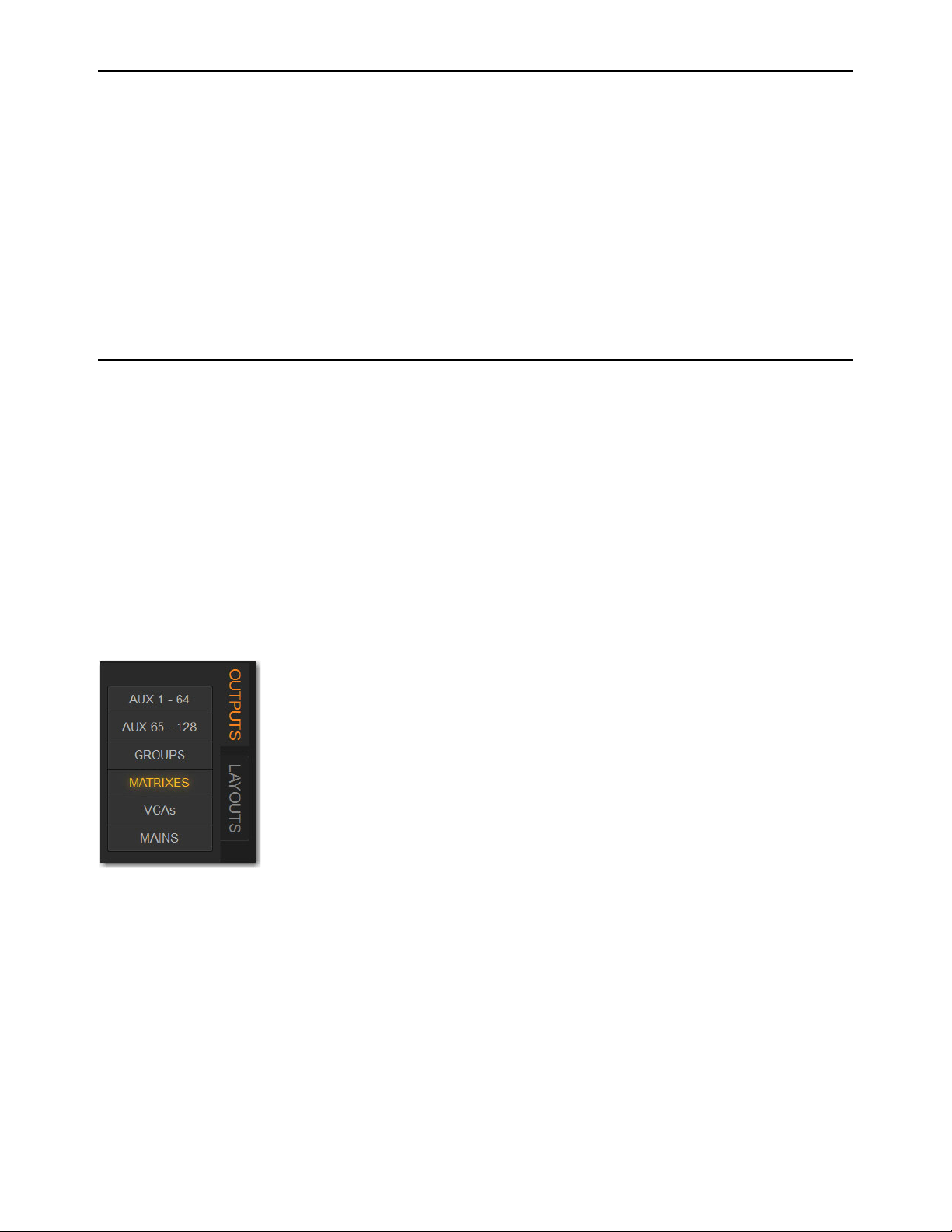
Matrix Mixers 152
Delay Compensation with Matrix Mixers
VENUE automatically compensates for the delay offsets that can arise when combining different signal paths within a Matrix
mixer.
Additional Information about Delay Compensation
• The overall latency through a Matrix is determined by the path with the highest latency.
• All inputs within a Matrix mix are guaranteed to be phase accurate, but mixes are not necessarily aligned to each other. This
ensures that all mixes are not penalized in the case of one or more exceptionally high-latency signal paths.
• Delay compensation only accounts for a channel’s post-insert pickoff. Channels that feed User Inputs and Auxes (pre-insert)
will not be fully compensated for.
• Any latency associated with Monitor buses is not included in the calculation of delay compensation for the corresponding Ma-
trix.
Adjusting Matrix Mixer Output Controls
You can bank Matrix Mixer outputs to the S6L’s faders and adjust level, solo, and mute using the channel strips. You can select
Matrix Mixers to adjust built in EQ and dynamics using the encoders on the associated CKM in Channel Control mode.
Each Matrix Mixer features the same output processing capabilities as other output channels: a built-in 7-band parametric EQ, a
built-in compressor/limiter, four plug-in slots (and one hardware insert slot), and the ability to insert a built in 31-band graphic EQ.
Accessing Matrix Mixer Output Processing on the External Screen.
You can adjust Matrix Mixer output parameters using the external screen, or by spilling them to the faders.
To access Matrix Mixer processing parameters on the external screen:
1 On the external screen, go to the Outputs page.
2 Select the Outputs tab, then select the Matrixes Channel Type button.
3 Attention the desired Matrix Mixer(s).
4 Select the CHANNEL tab to access built-in channel EQ and Comp/Lim
5 Select the GEQ tab to insert and adjust built-in GEQs. For more information see
Adjusting Parameters on the External
Screen.
To spill Matrix Outputs to the faders:
See Spill Mode for Outputs.
Output Channel Type buttons

Matrix Mixers 153
Snapshot Data and Parameters for Matrix Mixers
Snapshots can store and recall all source assignments of each matrix mixer when the Matrix (“Mtx”) data type is scoped, as shown
in the following table.
The Recall Safe tab of the Snapshots page provides two data “Mix” data types that let you discretely “safe” source and/or user input
assignments to prevent them from being changed with a snapshot recall.
For complete information on VENUE snapshots, see
Snapshots.
Table 1. Snapshot data types and parameters for Matrix mixers
Snapshot Data Type Included Parameters (for Each Scoped Channel Strip)
MTX Mixer Input Sources and pickoffs; Mixer Input level, Mixer Input on/off state and Mixer Input Link state

Muting and Mute Groups 154
Muting and Mute Groups
Channels can be muted on the S6L system in two ways:
Explicitly
Using the channel strip Mute switch on the control surface, from the MTS, or from the fader strips on the Inputs and Out-
puts pages of external screen. Mute switches light solid red when they are explicitly muted.
Implicitly
As a member of a Mute Group or VCA, or when any other channel is soloed in SIP (Solo in Place) mode. Mute switches
flash when they are implicitly muted.
This chapter shows how to do the following:
• Mute Individual Channels
• Use Mute Groups
Muting Individual Channels
Explicit Mute
You can mute individual channels using the channel strip Mute switch, from the MTS, or from the external screen. Muting indi-
vidual channels always behaves in additive (latched) fashion. You can mute individual channels in any sequence, and they will re-
main muted until they are un-muted. Muting individual channels always mutes them explicitly.
Channel mute has the following characteristics, depending on the type of channel muted.
Input Channels
Channel mute is pre-fader on input channels.
Output Channels
Mute operation is post-fader on all types of Output buses.
Mains
Only the linked Main buses are muted/unmuted. See Linking/Unlinking Mains.
VCAs
When you mute a VCA, its member channels are muted. The VCA mute indicator lights solid red, and the member channel
Mute indicators flash to show they are muted as part of a VCA.
To toggle mute on individual channels from the channel strip:
1 Bank to the desired channels.
2 Press the Mute switch.
Mute lights solid red to indicate the channel is muted.

Muting and Mute Groups 155
To toggle mute on individual channels from the MTS:
1 Touch Universe to show the Universe view.
2 Touch a Channel Tile Type button (Inputs, Auxes Groups, Matrixes, VCAs or Mains) to access the desired channel(s) on the
MTS.
3 Touch the Mute Channel Tile Function button.
4 Touch a Channel Tile.
The Channel Tile is bordered in red and the Channel Tile Mute LED lights solid red to indicate the channel is muted.
To toggle mute on individual channels from an external screen fader strip:
1 Select the Overview, Inputs, or Outputs page.
2 Select the Mute button on the desired channels’ fader strip so it is lit.
Mute Channel Tile Function button
A Channel Tile showing a muted input channel
Fader strip Mute button enabled
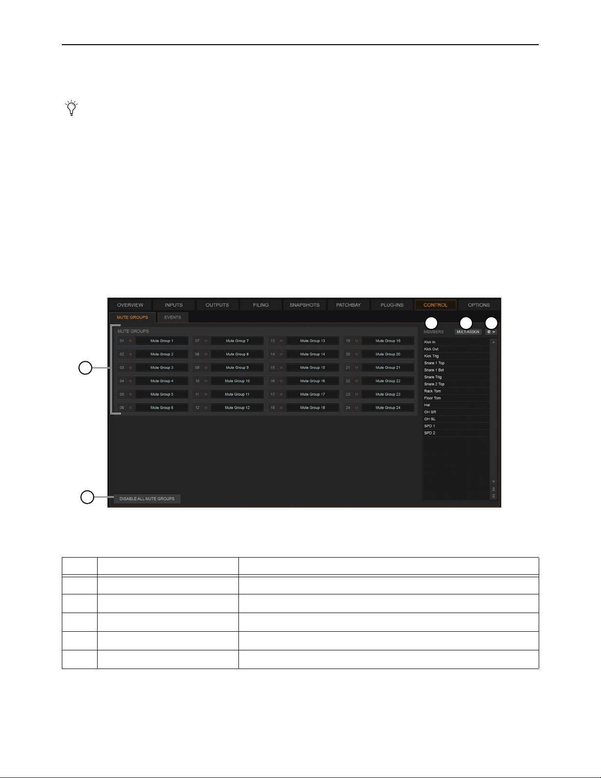
Muting and Mute Groups 156
Mute Groups
Mute Groups let you mute and un-mute multiple channels simultaneously by pressing a single switch. This section shows how to
assign channels to Mute Groups, and toggle them on/off.
Assigning Channels to Mute Groups
You can assign any types of channels to Mute Groups except VCAs. You can also assign a Channel to multiple Mute Groups. Chan-
nels can be assigned and managed in the Mute Groups tab of the Control page on the external screen, where you can also give Mute
Groups custom names. You can also assign channels to Mute Groups using the MTS, or from the channel encoders in Channel Con-
trol mode.
Assigning and Managing Mute Groups in the Mute Groups Tab
The Control tab provides a Mute Groups sub-tab in which you can manage assignments and name your Mute Groups.
To access the Mute Groups tab:
Navigate the external screen to Control > Mute Groups.
The Mute Groups tab provides the following features as shown in the figure above.
Mute Groups only affect the status of channel Mute switches, and do not affect the on/off status of Aux Sends, output of the Talk-
back/Oscillator section, or the routing of signals to the monitor outputs.
Control > Mute Groups
Mute Groups tab
Item Description
1
Access to up to 24 Mute Groups 24 selectable Mute Groups, each with Mute button and editable name
2
Members list List of channels assigned to the currently selected Mute Group
3
Multi-Assign button Enables/disables Assign to Mute Groups mode
4
Settings cog (gear icon) Commands to manage Mute Group assignments
5
Disable All Mute Groups button To disable (suspend) and re-enable all Mute Groups
1
2 3 4
5
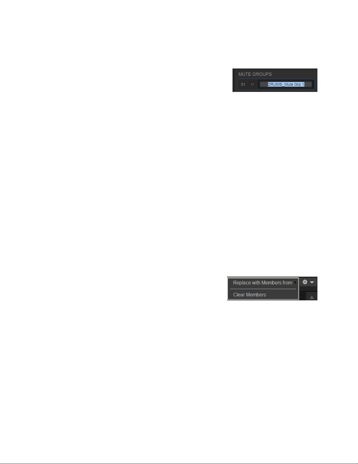
Muting and Mute Groups 157
To select a Mute Group:
Click its box in the Mute Groups tab. The selected Mute Group becomes outlined in blue and the Members list shows all chan-
nels assigned to that Mute Group.
To name a Mute Group:
1 Double-click any Mute Group name (such as Mute Group 1).
2 Enter a custom name and press Enter.
Mute Group names are shown on the MLM in the left column of the right Soft Keys.
To assign channels to the selected Mute Group:
1 Select the Multi-Assign button above the Members List.
2 Select the desired channels (on the control surface or on-screen) then press the flashing Multi-Assign button to confirm.
To toggle a Mute Group (mute/unmute its channels) from the external screen:
On the external screen, press the Mute button for that Mute Group.
You can also toggle a Mute Group on/off using the Right Soft Keys on MLM. Mute Groups 1–6 are available from the first page
of the Right Soft Keys menu. Mute Groups 1–24 are available on the Mute Group sub-pages.
To toggle Mute Groups using the MLM:
1 In the left-hand column of the Right Soft Keys display, locate any Mute Group 1–6 that you want to activate.
To access all Mute Groups (1–24) press the Mute Groups key in the right-hand column of the Right Soft Keys display.
2 To turn a Mute Group on, press the corresponding Soft Key so it lights.
3 To turn the Mute Group off, press the corresponding Soft Key so it is unlit.
To disable all Mute Groups from the external screen:
In Control > Mute Groups, press Disable All Mute Groups.
The Disable All Mute Groups button lights red and the Mute Groups alert appears on the external screen. To enable Mute Groups
press
Disable All Mute Groups again (it becomes unlit) or press Enable Mute Groups in the on-screen alert.
To create a new Mute Group with the members of an existing Mute Group:
1 Select the Mute Group you want to define.
2 Click the Settings cog (gear icon) and choose Replace with Members from, then
choose an existing Mute Group from the hierarchical sub-menu.
To remove a member from a Mute Group:
1 Right-click the channel in the Mute Group Members list and choose Unassign.
To clear a Mute Group:
1 Select the Mute Group you want to clear.
2 Click the Settings cog (gear icon) and choose Clear Members.
To attention a member of a Mute Group:
Select the channel in the Mute Group Members list.
Entering a custom name for a Mute Group
Mute Groups menu
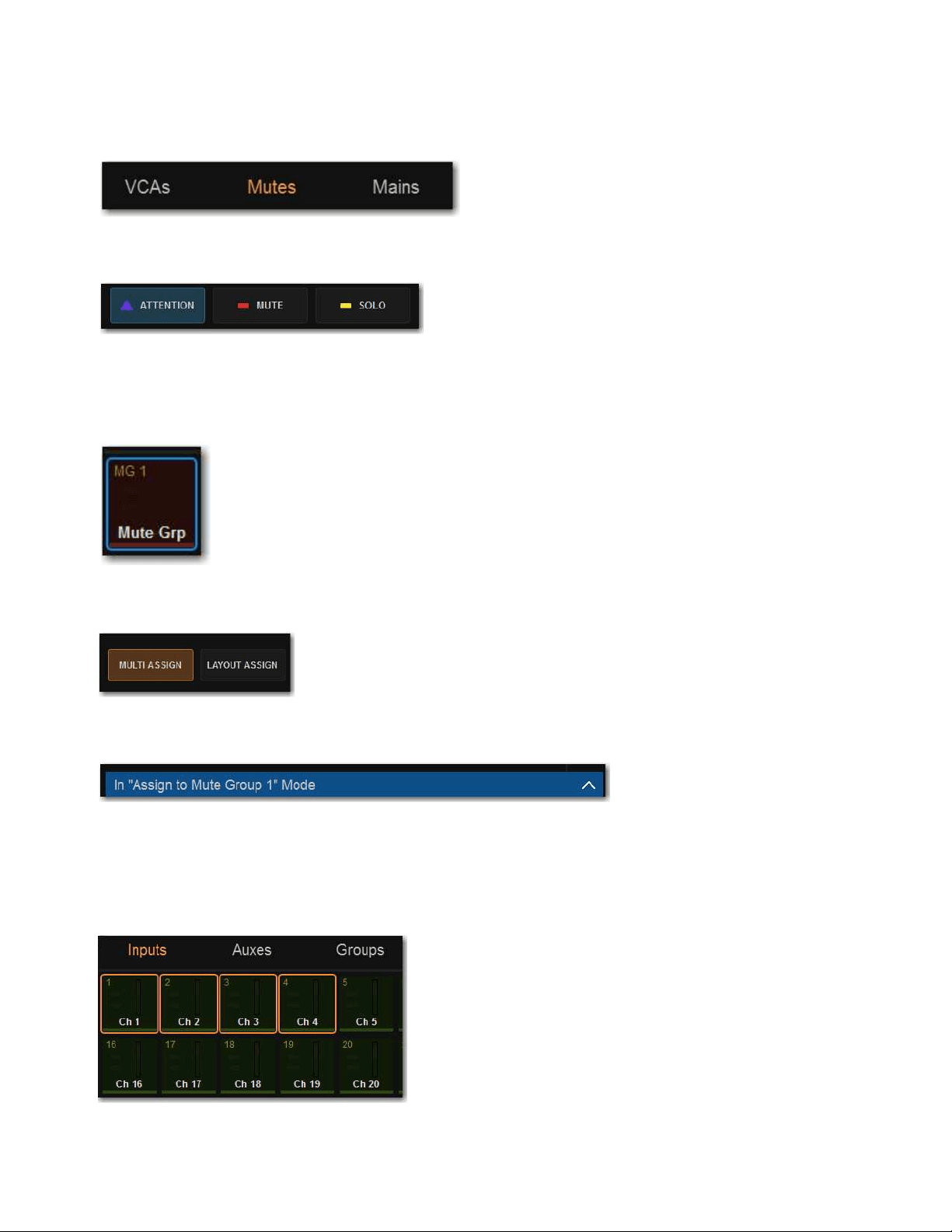
Muting and Mute Groups 158
Assigning Channels to Mute Groups Using the MTS and Channel Strips
To add or remove members of a Mute Group:
1 On the MTS, touch Mutes.
2 Touch the Attention Channel Tile Function button.
3 Touch the desired Mute Group Channel Tile so it is bordered in blue (attentioned) to target that Mute Group for the assignments.
The text in the upper left corner of the Channel Tile (such as MG 1 and MG 2) indicate the Mute Group number the Channel Tile
corresponds to.
4 Touch Multi-Assign on the MTS.
In the banner display on the external screen, a message appears indicating that the system is in Mute Group assign mode.
5 To add/remove channels using the MTS:
• Touch a Channel Tile Type button (Inputs, Auxes Groups, Matrixes, or Mains) to access those types of channels on the MTS.
• Touch any Channel Tiles so it is bordered in orange to add them to the Mute Group.
• Touch a Channel Tile so the orange border disappears to remove that channel from the Mute Group.
Mute Channel Tile Types button
An enabled Attention Channel Tile Function button
An attentioned Mute Group Channel Tile
Enabled Multi-Assign button on the MTS
Banner Display message indicating that Mute Group assign mode is active
Channel Tiles targeted for Mute Group assignment
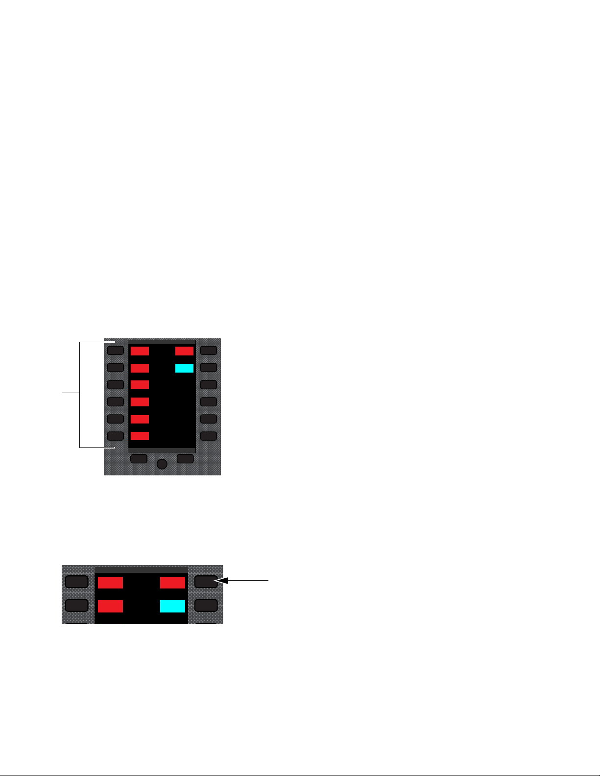
Muting and Mute Groups 159
6 To add/remove channels using the channel strips:
• Bank to the desired channels.
• Press any channel strip
Attention switches to add them to the Mute Group. Selected Attention switches flash.
• Press a flashing Attention switch so it no longer flashes to remove it from the Mute Group.
7 To confirm the assignments and exit Multi-Assign mode on the MTS tap Multi-Assign so it is unlit.
• To cancel the assignments and exit Multi-Assign mode, touch the banner display message to expand the message, the select
Cancel.
To assign channels to Mute Groups in Channel Control mode:
See
Assign VCAs and Mute Groups from Channel Control Encoders.
Toggling Mute Groups On/Off
You can toggle a Mute Group on/off using the Right Soft Keys on MLM, or using the MTS. Mute Groups 1–6 are available from
the first page of the Right Soft Keys menu. Mute Groups 1–24 are available on the Mute Group sub-pages.
Using the MLM
To toggle Mute Groups 1–6 using the MLM:
1 In the left-hand column of the Right Soft Keys display, locate any Mute Group 1–6 that you want to activate.
2 To turn a Mute Group on, press the corresponding Soft Key so it lights. The channels in that Mute Group are implicitly muted,
and their Mute switches (on the control surface) and Mute buttons (on the external screen) flash red.
3 To turn the Mute Group off, press the corresponding Soft Key so it is unlit.
To access all Mute Groups:
1 In the right-hand column of the Right Soft Keys display, locate Mute Group and press the corresponding Soft Key. Mute Groups
1–12 are shown in the display.
Right Soft Keys and display showing the main menu
Mute Group Soft Key
Global Controls
Mute Group 1
Mute Group
Function KeysMute Group 2
Mute Group 3
Mute Group 4
Mute Group 5
Mute Group 6
M1
M2
M3
M4
M5
M6
Global Controls
Mute Group 1
Mute Group
Function KeysMute Group 2
M1
M2
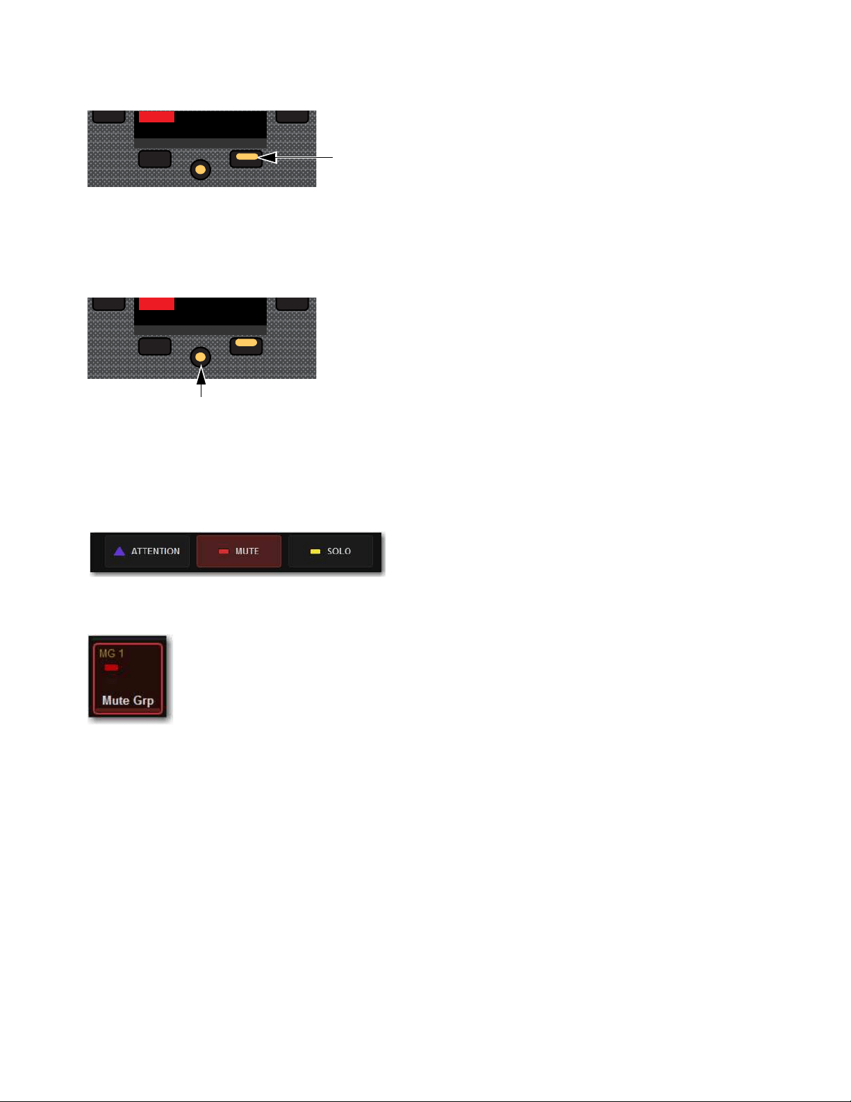
Muting and Mute Groups 160
2 Press any Soft Key to activate the corresponding Mute Group.
• Or press the lit Next switch to access Mute Group 13–24, then press the corresponding Soft Key.
The channels in that Mute Group are implicitly muted, and their Mute switches flash red.
To return to the first page of the Left Soft Keys menu:
Press the lit HOME switch.
Using the MTS
To toggle a Mute Group from the MTS:
1 On the MTS, touch Mutes.
2 Touch the Mute Channel Tile Function button.
3 To turn a Mute Group on, touch the desired Mute Group Channel Tile so it is bordered in red and the Solo LED is lit red.
4 To turn the Mute Group off, touch the Mute Group Channel Tile so it is no longer bordered in red and LED turns off.
Next Page switch
Home switch
Mute Channel Tile Function button
An enabled Mute Group Channel Tile
Mute Group 6
M6
Next
Mute Group 6
M6
NextHome
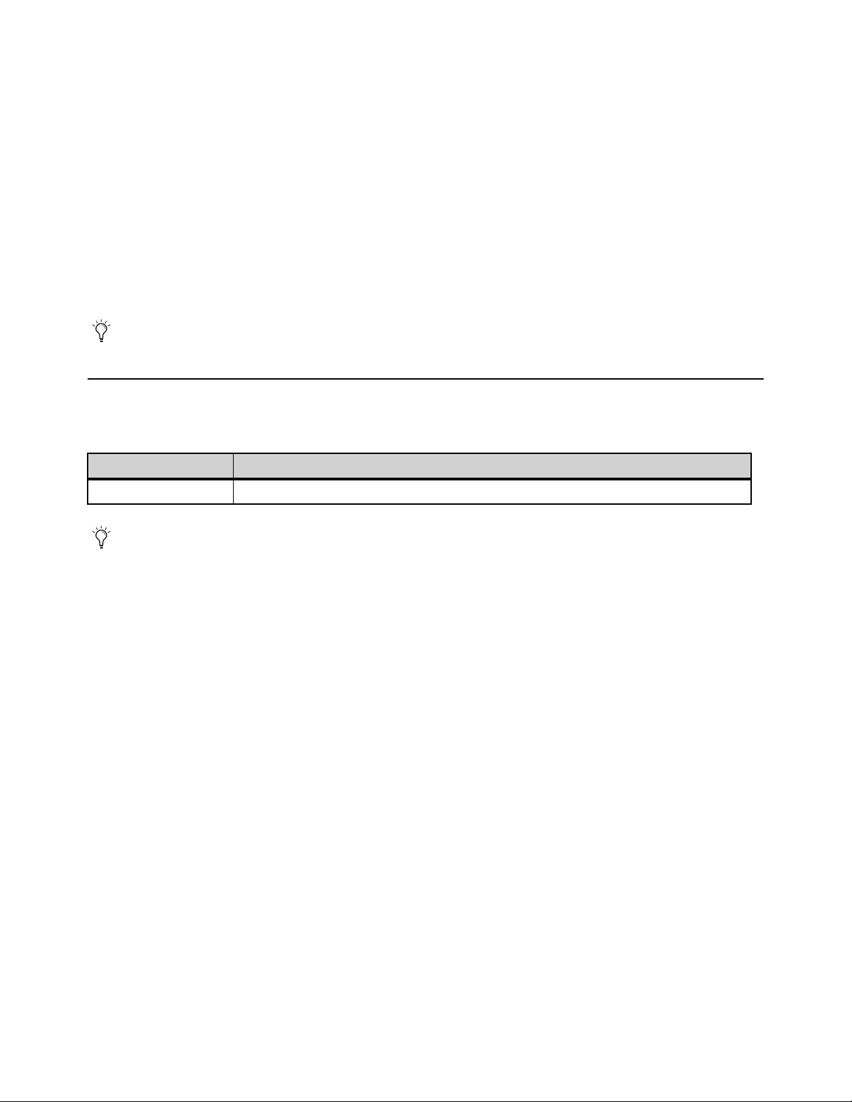
Muting and Mute Groups 161
Explicit and Implicit Channel Mute with Mute Groups and VCAs
Any input or output channel implicitly muted by a Mute Group or VCA can be explicitly un-muted, explicitly muted, and reset to
its implicit mute state by repeatedly pressing a channel Mute switch. Explicitly unmuting or muting a channel in this way does not
permanently remove that channel from the Mute Group or VCA.
This feature is useful to temporarily unmute a channel during a line check without having to release the entire Mute Group or VCA.
To cycle through the available Mute modes:
1 Activate a Mute Group, or mute a VCA. The Mute switches on all implicitly muted channels flash.
2 Press a flashing channel strip Mute switch to explicitly un-mute the channel. Its Mute switch is now unlit.
3 Press the same (now unlit) Mute switch again to explicitly mute the channel. The Mute switch is now lit solid.
4 Press the same Mute switch again to implicitly mute the channel and return it to being controlled by the active Mute Group or
VCA. Its Mute switch resumes flashing.
Snapshot Data and Parameters for Mute
Snapshots can store and recall mute status when the MUTE data type is scoped, as shown in the following table:
For complete information on VENUE snapshots, see Snapshots..
Select multiple channels first to be able to toggle all their states at once. The Mute behavior may vary if some, but not all, of the
selected channels are members of a Mute Group or VCA.
Table 2. Snapshot data types and parameters for Matrix mixers
Snapshot Data Type Included Parameters (for Each Scoped Channel Strip)
MUTE Explicitly muted channels, and channels implicitly muted via VCA mute.
Mute Group state and assignments cannot be stored nor recalled via Snapshots. Mute Group state and information is stored
with the Show file.

Soloing and the Monitor Buses 162
Soloing and the Monitor Buses
The S6L system provides two discrete, independently configurable Monitor buses, as well as two discrete headphone outputs on
S6L-32D/24D/24C, each of which is also independently configurable. S6L-16C provides a single headphone output. You can route
individual channels to either or both Monitor buses, and feed each Monitor bus to discrete hardware outputs and the headphone out-
puts.
This chapter shows how to configure the Monitor buses and soloing options on the S6L system, how to adjust the Monitor buses,
how to solo channels, and how to use the headphone outputs.
Configuring the Monitor Buses and Solo Options
The S6L system provides two discrete Monitor buses. Each bus is independently configurable. You configure your Monitor buses
using the Options > Buses page of the external screen.
Selecting a Solo Mode
Three Solo modes are offered for input channels: Pre-Fader Listen (PFL), After-Fader Listen (AFL) and Solo In Place (SIP). Out-
puts are always soloed in AFL mode. You can also toggle Solo modes using the AFL switch in the Monitoring section on the MLM.
To select a Solo mode:
1 On the external screen, go to the Options > Buses page.
2 Under Solo and Monitor Operation, select the Type pop-up menu and choose one the following Solo modes:
Pre-Fader Listen (PFL)
PFL Solo mode sends the signal from explicitly soloed input channels to the Monitor bus. The signal is
post-insert, pre-fader and pre-mute. Mono input signals are sent to both sides of the Solo bus, and the left and right sides of stereo
input signals are sent to the corresponding sides of the Monitor bus. PFL is the default Solo mode.
After-Fader Listen (Stereo AFL)
AFL Solo mode sends the signal from explicitly soloed channels and solo-safe inputs to the Mon-
itor bus. Soloing of outputs is always AFL. In AFL Solo mode, both input and output signals are sent to the Monitor bus post-fader
and post-pan/balance, and are always panned to stereo even if the Main buses are configured in L–C–R mode.
Solo In Place (SIP)
SIP mode applies to input channels only. SIP sends the signal from the soloed channel(s) to the Mains buses,
bypassing the Monitor bus. Signal is sent post-pan/balance. Show files do not open in SIP mode. If you save a Show file while in
SIP, when you reopen the Show file, it will open in PFL Solo mode.
Monitor Bus options on the Options > Buses page
In SIP mode, the soled channel(s) is (are) sent directly to the Main buses. Use this feature only at soundcheck.

Soloing and the Monitor Buses 163
Sends on Faders Follow AFL
When Sends on Faders Follow AFL is enabled, soling an Aux output simultaneously assigns its sends to the faders and routes the
Aux output’s signal to the Monitor bus (in AFL solo mode). Sends on Faders Follow AFL is enabled on each Monitor bus inde-
pendently. When enabling Sends on Faders, make sure to enable it on the Monitor bus your input channels are currently routed to
(assuming you want all input channels to be subject to Sends on Faders).
You can, for example, route some of your input channels to Monitor bus A with Sends on Faders disabled, and route other channels
to the other Monitor bus B with Sends on Faders enabled. You can then route each Monitor bus to a discrete hardware or headphone
output. If any input channels are targeted to both Monitor buses, then enabling Sends on Faders on either Monitor bus results in
Sends on Faders behavior for that channel.
To enable Sends on Faders:
1 On the external screen, go to the Options > Buses page.
2 Under Monitor Bus A or Monitor Bus B, select Sends on Faders Follows AFL so it is checked.
AFL Follows Sends on Faders
When AFL Follows Sends on Faders is enabled, entering Sends on Faders mode for an Aux solos that Aux output (requires that
the Monitor bus to which the Aux is assigned is configured for Stereo AFL). The AFL Follows Sends on Faders setting is stored
and recalled with each Show file. By default, the option is off (not selected).
To set AFL to follow Aux encoder assignment:
1 Go to the Options > Buses page.
2 In the Solo and Monitor Operations section, select the AFL Follows Sends on Faders option.
Select Follows Solo
See Select Follows Solo.
Auto Cancel and Input Priority
The Auto Cancel option determines whether Solo switches cancel other soloed channels or are additive (latching). The Input Pri-
ority option determines whether soloed inputs replace soloed outputs on the AFL/PFL Solo bus.
Auto Cancel On, Input Priority Off
A solo cancels all other solos (inputs and outputs)
Auto Cancel On, Input Priority On
An input solo cancels all other soloed inputs; an output solo cancels all other output solos; so-
loed inputs temporarily replace soloed outputs
Auto Cancel Off, Input Priority Off
Solos are additive, and soloed inputs and outputs are heard together
Auto Cancel Off, Input Priority On
Solos are additive, and soloed inputs temporarily replace soloed outputs.
Sending the Mains Mix to Monitors
This option sends the Mains mix signal to the selected Monitor bus. When enabled (lit), whenever channels are not soloed the Main
mix is present in the Headphones output (Phones A or B) that the Monitor bus is routed to (or to near-field monitors when a hard-
ware output is patched to the Monitor bus). This option mirrors the functionality of the
Mix to Monitors switch.
To send the Main mix to the Monitor bus:
Press Mix to Mons on the MLM on the S6L control surface.
– or –
Go to the Options > Buses page and select the Mix to Monitors option.
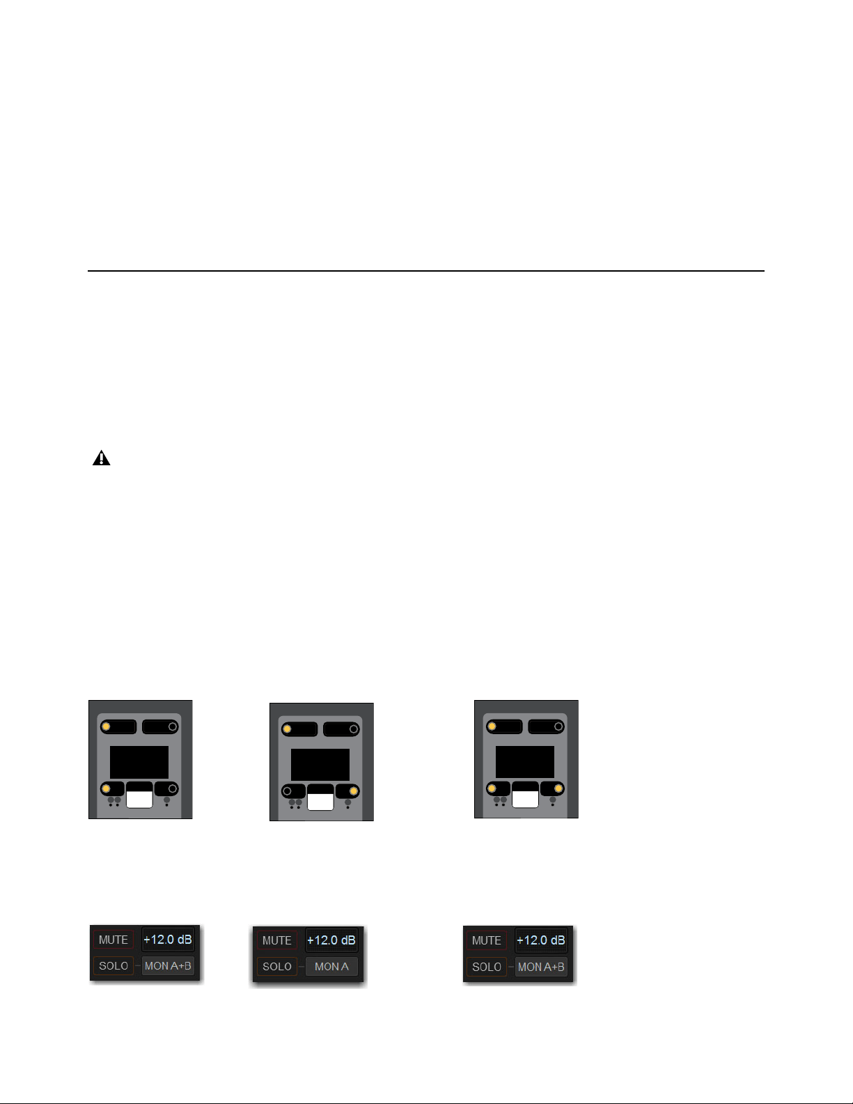
Soloing and the Monitor Buses 164
Monitor Output from an L-C-R Main Mix
The stereo Mix to Monitors signal is derived from the L–C–R Main mix by adding a –3 dB signal from the Center channel to the
Left and Right monitor channels.
Monitor Output from an L–R+M Main Mix
In a L–R+M Main mix, only the Left and Right channels are heard in the Monitor bus.
Listen to Monitors
This feature is not yet implemented.
Adjusting Monitor Buses
You can route and adjust Monitor bus levels using the S6L control surface or the external screen. You can apply a delay to each
Monitor bus on the external screen.
Routing Channels to the Monitor Buses
You can route any channel to either or both Monitor buses independently. You can route channels to Monitor buses using the chan-
nel strip Channel Menu and the external screen. By default, all channels are routed to Monitor Bus A. When you solo a channel,
the soloed signal is sent to the Monitor bus.
To route channels to the Monitor buses using the Channel Menu:
1 Bank the desired channels to the control surface’s faders.
2 Press the channel strip Menu switch until Monitor appears in the channel display.
3 To route the channel to Monitor Bus B, press the Left Menu switch so it is unlit. The Right Menu switch lights. Mon B appears
in the channel display, and on the CTM and MTS in Channel view.
4 To route the channel back to Monitor Bus A, press the Right Menu switch so it is unlit. The Left Menu switch lights. Mon A ap-
pears in the channel display, and on the CTM and MTS in Channel view.
5 To route channels to both Monitor buses, press the Left and Right Menu switches so they are both lit.
Mon A+B appears in the channel display, and on the CTM and MTS in Channel view.
To route channels to the Monitor Buses on the external screen:
1 Navigate to the desired channel on the Inputs or Outputs page of the external screen.
2 Select the Mons A/B/A+B button to cycle through the three Monitor Bus routing options for the attentioned channel.
When a channel is routed to both Monitor buses, any solo and monitoring options set on either bus affect the behavior of that
channel when soloed.
A channel display showing a channel routed to Monitor Bus A (Left) Bus B (center) and Buses A and B (right)
External screen showing a channel routed to Monitor Bus A (Left) Bus B (center) and Buses A and B (right)
Menu Safe
Mute
AS B
Mon B
Monitor
Menu Safe
Mute
AS B
Mon A
Monitor
Menu Safe
Mute
AS B
Mon A+B
Monitor

Soloing and the Monitor Buses 165
Adjusting Monitor Bus Level
The Monitoring encoder on the MLM lets you target a Monitor bus for level control of the targeted Monitor bus.
To adjust the level of a Monitor bus on the control surface:
1 Push the encoder to target the encoder to Monitor bus A or B. The A or B LED lights to indicate the currently targeted Monitor
bus.
2 Rotate the encoder to adjust the level for the targeted Monitor bus. Monitor bus levels are indicated on the Monitor Bar at the
bottom of the MTS.
To adjust the level for the Monitor bus on the external screen:
1 Go to Options > Buses.
2 In the Solo and Monitor Operations section, adjust the Monitoring encoder.
Delaying a Monitor Bus
You can delay a Monitor bus to time-align it with the sound coming from the stage.
To adjust monitor bus delay:
1 On the external screen, go to Options > Buses.
2 Select the In button beneath the on-screen encoder to enable Delay for the desired Monitor bus.
3 Select the Delay encoder in the section and drag to adjust. When lit, the Delay setting is applied to the monitor output.
Routing the Monitor Bus to Outputs and Plug-Ins
The Monitor bus can be routed to hardware outputs and to bus-fed plug-ins.
Hardware Outputs
For routing to hardware outputs, the Monitor (Solo) bus outputs are available in the Mains tab of the Patchbay
> Outputs page. Monitor bus outputs are assignable to any number of physical outputs on the system. Use this capability to route
monitor outputs to multiple cue stations (in-ear mix and wedge mix), to an outboard analyzer, to a listen wedge mix, or to near-field
monitors. Monitor busses can also be assigned as Matrix input sources.
Bus-Fed Plug-Ins
For routing to bus-fed plug-ins, the Monitor bus appears as a choice in the plug-in routing selector. This lets you
route the Monitor bus to a bus-fed stereo plug-in such as an onboard analyzer. Plug-ins can not be inserted on the Monitor bus.
Routing the Monitor Bus to Hardware Outputs
To route the Monitor bus to hardware outputs:
1 In the Patchbay, select the Outputs tab, then select the Mains tab.
2 Select a Hardware I/O tab to select the desired hardware output.
3 Select in the grid to assign the desired Monitor bus to the desired destination.
Routing the Monitor Bus to Plug-Ins
To route Monitor output to a bus-fed plug-in:
1 On the external screen, go to the Plug-Ins page.
2 Make sure the desired stereo plug-in is installed and assigned to a rack slot.
3 Select the Plug-In Input selector at the top of the corresponding rack slot, and choose Bus Outs > Mains > Monitor - stereo.
Monitor Bar
Solo In Place, when engaged, is simultaneously routed to the Main and Monitor buses.
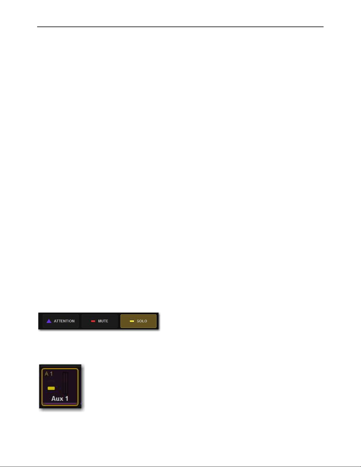
Soloing and the Monitor Buses 166
Soloing Channels
Solo operation depends on the type of channel being soloed, and on any selected solo options. In all modes, a channel’s Solo switch
lights to indicate that the channel is soloed.
Input Channels
Soloing an Input Channel sends signal to the Solo bus (when in PFL or AFL modes) or to the Mains bus (when in
SIP mode). In SIP mode only, when a channel is soloed, all other channels that are not soloed or solo safe are implicitly muted. Im-
plicit mutes are indicated by a flashing mute switch.
Output Buses
Soloing an output channel sends signal to the AFL/PFL Solo bus. This applies to Groups, Auxes, and Matrixes. Out-
puts are always AFL. Stereo buses use true stereo AFL. When you solo a stereo bus, the two buses are heard as a stereo pair when
soloed. Mono buses are heard as dual mono when soloed.
Momentary And Latching Switch Operation
Channel strip Solo switches can operate with either momentary or latching behavior.
To engage momentary solo on a channel:
Hold the Solo switch for more than one second. Release the solo switch to un-solo the channel.
To latch solo on a channel:
Press and release the Solo switch. Press the switch a second time to unsolo the channel.
Soloing Single Channels
You can solo channels from the channel strip, the MTS, and the external screen.
To solo a single channel from the channel strip:
Press a channel strip Solo switch so it lights. The solo switch latches on a momentary press.
– or –
Hold the channel Solo switch for more than one second for momentary solo. The channel will automatically unsolo when you
release the switch.
To toggle solo from the MTS:
1 Touch Universe to show the Universe view.
2 Touch the appropriate Channel Type button (Inputs, Auxes, Groups, Matrixes, VCAs, or Mains) to show the channel you want
to solo.
3 Touch the SOLO Channel Tile Function button so it lights.
4 Touch the a Channel Tile. The Channel Tile is bordered in yellow and the Channel Tile Mute LED lights solid yellow to indicate
the channel is muted.
Solo Channel Tile Function button
A Channel Tile showing a soloed Aux output
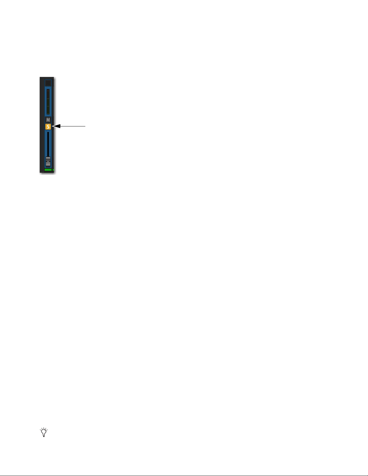
Soloing and the Monitor Buses 167
To toggle solo on a single channel from an external screen fader strips:
1 Select the Overview, Inputs, or Outputs page:
2 Select the Solo button on the desired channels’ fader strip so it is lit.
– or –
• From the Inputs or Outputs page
Soloing Multiple Channels
You can solo multiple channels using channel strip Solo switches.
To solo multiple channels:
1 Bank the desired channels to the faders.
2 Do one of the following:
With the Auto Cancel option enabled, press the Solo switches on multiple channel strips simultaneously.
– or –
Hold Multi-Select and press the Solo switches on one or more channel strips.
– or –
With the Auto Cancel option disabled, press Solo switches on multiple channels in any sequence. The Solo switches latch on.
Toggling the Solo Status of Multiple Channels
To toggle the Solo status of multiple channels, do one of the following:
With the Auto Cancel option enabled, hold the Multi Select switch while pressing the Solo switches on channels you want to
toggle.
With the Auto Cancel option disabled, press Solo switches in any sequence. The Solo switches latch on and off.
Soloing VCAs
When you solo a VCA, its member channels are soloed. If the VCA members include a combination of input and output channels,
their solo status follows any selected solo options.
Clearing Solos
To clear all soloed channels:
Press the flashing Solo Clear switch to clear all soloed channels.
Fader strip Solo button enabled
The Events list can be used to assign the Solo Clear function to a footswitch or any other available trigger.
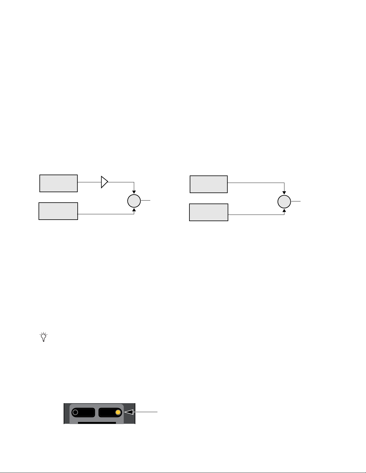
Soloing and the Monitor Buses 168
Solo Bus Metering
When a channel or dynamics key input is sent to the Solo bus, its signal is metered on the Selected Channel meters, temporarily re-
placing the metering for any currently targeted channel.
Trimming Solo Bus Level
PFL Solo bus monitoring levels can be controlled by the on-screen Level Trim control in the Solo and Monitor Operations section.
The trim amount is adjustable over a range of –20 dB to +20 dB.
PFL signals are frequently hotter than AFL signals. Because Level Trim only affects PFL signals, you can use Level Trim to bal-
ance PFL volume levels with AFL or Mix to Monitors volume levels, with a minimum of Monitoring level adjustment during a
show.
To trim the Solo bus level:
1 Solo a channel.
2 Go to Options > Buses, and adjust the Level Trim setting in the Solo and Monitor Operations section.
The following diagrams show the signal flow for PFL and AFL modes.
Solo Safing Channels
Solo Safing an input channel prevents that channel from being implicitly muted when any other channel is soloed. Solo safed chan-
nels are automatically added to any explicitly soloed channels. Solo Safe only applies to SIP and AFL solo modes. Solo safe status
is ignored in PFL mode.
You can Solo Safe channels using the Channel Safe
switches and on the external screen fader strips. You can also Solo Safe a chan-
nel using the CKM in Channel Control mode. Solo Safe mode is enabled on the Options > Interactions
page.
To enable Solo Safe for the Channel Safe switches:
1 On the external screen, go to the Options > Interaction page.
2 In the Channel Safe Switches section, under Inputs and Outputs, select Solo Safes as desired.
To Solo Safe channels using the Channel Safe switches:
1 Make sure you have enabled Bank Safe for the Channel Safe switches.
2 On the S6L control surface, do the following:
• Bank the desired channel to the faders.
• Press Safe for the channel you want Solo Safe.
Level Trim in PFL mode (left) and no Level Trim in AFL mode (right)
You can create an event that lets you cycle through the various Channel Safe switch modes, as well as suspend or disable Bank
Safe (Disable Bank Switch). See
Creating Events.
S6L Channel Safe switch engaged
Input Channel
Solos (PFL)
Output Channel
Solos (AFL)
Level Trim (PFL)
To Monitor/
Headphones
+
Input Channel
Solos (AFL)
Output Channel
Solos (AFL)
To Monitor/
Headphones
+
Menu Safe
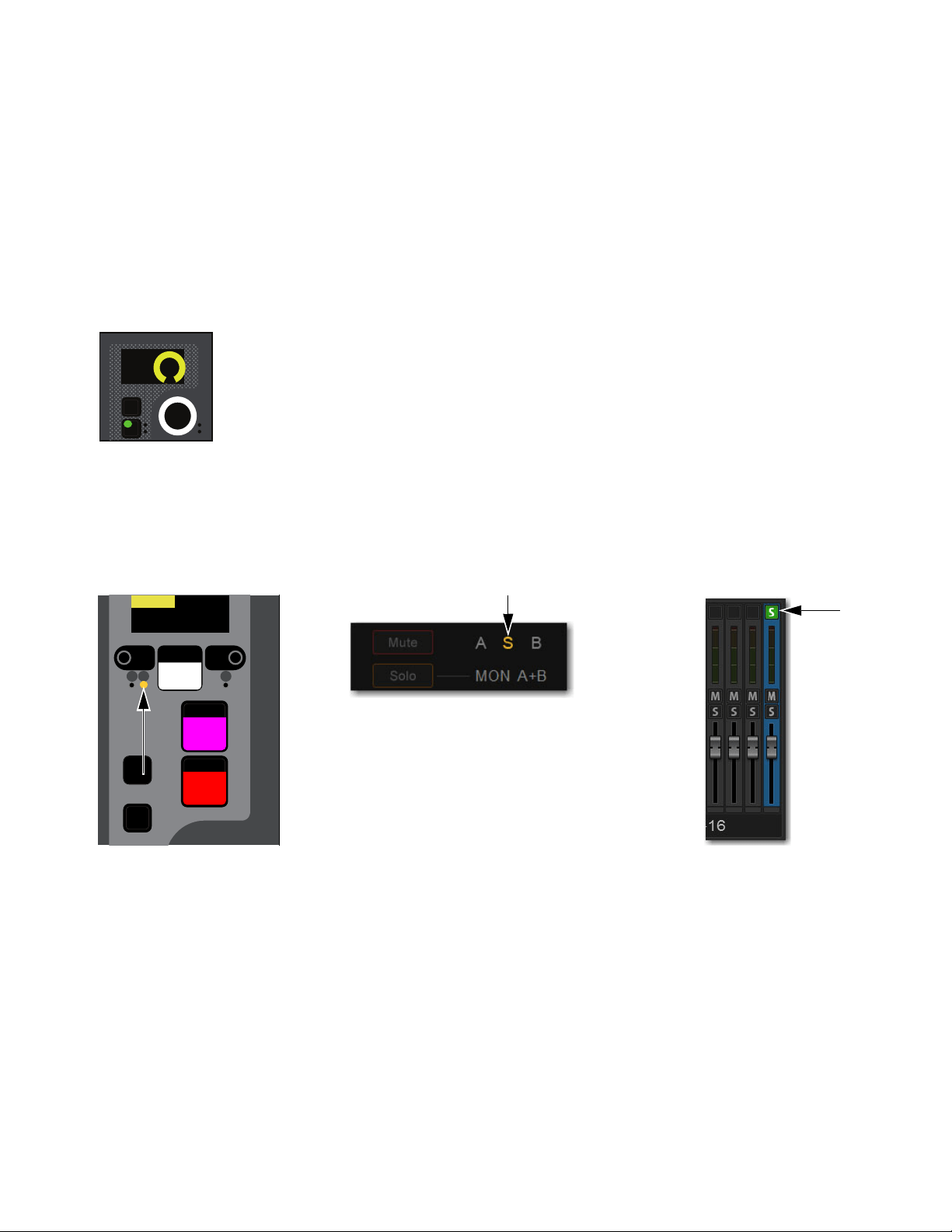
Soloing and the Monitor Buses 169
3 On the external screen, do the following:
• Go to the Inputs or Outputs page, and navigate to the desired channel using the provided tabs and buttons.
• Select the Channel Safe switch for the desired channel, located at the top of each fader strip.
Solo Safe a channel using the CKM:
1 Bank the desired channel to the faders.
2 Select the to Automation Safe so it lights, and then press the INPUT Channel Control Function switch so it lights.
– or –
• Touch the channel’s Input touch zone on the associated Channel Touch Module (CTM).
3 Locate the Solo Safe encoder, indicated by Solo Sf on the encoder display, and press the encoder.
The encoder In switch lights green, and the channel is Solo Safed.
Solo Safe status for the channel is indicated as follows:
• On the control surface channel strip, the S LED lights yellow.
• In the Input section of the MTS and CTM Channel view for the channel, S lights yellow.
• On the external screen the Safe button flashes green and shows the letter S (A appears if the switch is acting as an Automation
Safe, and B appears if it is acting as a Bank Safe).
Automation Safe parameter on a CKM encoder
Indications that a channel is Solo Safed on the channel strip (left) the MTS/CTM Channel view (center) and on the external screen (right)
In
Sel
Solo Sf
Select
Solo
Y
X
Mute
AS B
CH 1
Ch 1
0.0 dB

Soloing and the Monitor Buses 170
Using the Headphone Outputs
The front panel of the S6L-32D/24D/24C control surface provides two discrete headphone outputs (Phones A and B). S6L-16C
provide a single headphone output (Phones).
Configuring the Headphones Outputs
You can choose the Monitor bus that you want feeding each headphone output.
To configure the headphone output:
1 On the external screen, go to the Options > Busses page.
2 In the Headphones section, located the Phones A and Phones B pop-up menus. With S6L-32D/24D/24C, Phones A corresponds
to the left front-panel headphone jack, and Phones B corresponds to the right headphone jack.
3 Select a Phones pop-up menu, and choose one of the following:
• To feed Monitor Bus A to the headphone output, choose Mons A.
• To feed Monitor Bus B to the headphone output, choose Mons B.
Adjusting Headphone Level
Output level for each headphone output is controlled by its corresponding volume control located next to each headphone jack. The
overall level of the Monitor bus feeding the headphone output also contributes to the headphone level.
To adjust Headphone level:
Adjust the headphone volume control to adjust level as needed.
The headphone volume control is post-Monitor bus level. If no signal is present on headphones, make sure the level for the Mon-
itor bus is set properly.

Part III: External VENUE Software
Screen
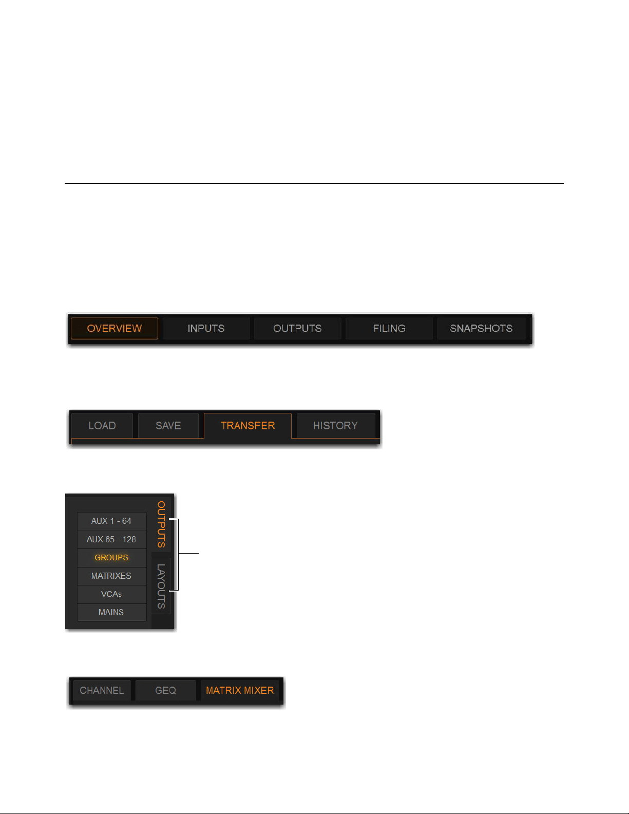
External VENUE Software Screen Overview 172
External VENUE Software Screen Overview
You do not need the external VENUE software screen to mix a performance, as all essential mixing controls are provided on the
S6L control surface. However, the external screen is essential when setting up and configuring the system before a performance.
Viewing Pages and Tabs
To access pages and sub-tabs on the external screen, use the buttons at the top of the external screen, F switches and Soft Keys on
the MLM, or the computer keyboard.
Using the External Screen
To view a page, do one of the following:
Select a Page button at the top of the screen so it lights orange.
To view a tab:
On the Overview, Filing, Snapshots, Patchbay, Control and Options pages, select a tab below the page names.
On the Inputs and Outputs pages, select the tabs along the side of the fader section to access those types of channels.
For output channels, select a tab below the page name to access processing functions for the currently attentioned channel.
Overview page button selected
Transfer tab of the Filing page selected
Outputs tab selected on the Outputs page
Matrix Mixer tab of a Matrix output selected

External VENUE Software Screen Overview 173
Using Switches on the MLM
The MLM provides F 1–5 switches in the Transport/Function switch section.
Transport/Function Switches
These dual-function switches provide dedicated switches to control the Pro Tools Transport, as well as programmable function
switches that you can use to control a wide range of system parameters using events.
When Trans is unlit, by default the switches target pages on the external screen, as follows:
F1
Targets the Inputs page.
F2
Targets the Outputs page.
F3
Targets the Snapshots page.
F4
Targets the Plug-Ins page.
F5
Targets the Options page.
To view a tab:
While viewing the Overview, Filing, Snapshots, Patchbay, Control or Options pages, press its corresponding F switch (1–5) re-
peatedly to cycle through available tabs.
Soft Keys
Function view on the MLM Soft Keys provide all default View mode events, letting you access Control, Overview, Filing, and
Patchbay pages and their tabs, in addition to Inputs, Outputs, Snapshots, Plug-ins, and Options.
To access Function view on the MLM:
1 Press the Function key in the right bank of MLM Soft Keys.
In Views with multiple tabs (such as Options) press its Soft Key repeatedly to cycle through its tabs.
2 To navigate to Functions 13–24, press the Soft Key below Next.
F1–5 switches
To see the default (factory) Function key assignments, use the
Clear Console command. All available Function Keys can be as-
signed and reassigned using Events.
Function switches (F1–F5), and Function Soft Keys
Flip
Trans
F1 F2 F3 F4 F5
NEXT
PREV
Encoder
Assign
Select
Clear
Tap
Tempo
Next
Mute Group 6
M6
VCA 9-16
9-16
Ch 81-96
81-96
Trans
F1 F2 F3 F4 F5
NEXT
PREV
Inputs/Outputs
Next
Global Controls
Mute Group 1
Mute Group
Function KeysMute Group 2
Mute Group 3
Mute Group 4
Mute Group 5
Mute Group 6
M1
M2
M3
M4
M5
M6
Ch 1-16
1-16
Aux 1-8
1-8
Aux 9-16
Aux 17-24
Aux 25-32
25-32
VCA 1-8
1-8
VCA 9-16
9-16
Ch 17-32
17-32 9-16
Ch 33-48
33-48 17-24
Ch 49-64
49-64
Ch 65-80
65-80
Ch 81-96
81-96
Global Controls
Overview (F7)
Filing (F8)
Patchbay (F9)
F 10
F 11
F 12
F 7
F 8
F 9
F 10
F 11
F 12
F 1
F 2
F 3
F 4
F 5
F 6
Inputs (F1)
Outputs (F2)
Snapshots (F3)
Plug-Ins (F4)
Options (F5)
Control (F6)

External VENUE Software Screen Overview 174
To access all Function Keys:
1 In the right Soft Keys on the MLM, press the switch for Function Keys.
The first 12 currently assigned Function switches appear in the Soft Keys.
To view a tab:
While viewing the Overview, Filing, Snapshots, Patchbay, Control or Options pages, press its corresponding F Soft Key repeat-
edly to cycle through available tabs.
By default, Function Soft Keys 1–9 target pages on the external screen (see Default F Key assignments and Keyboard Equiv-
alents). Target pages are shown in the Soft Key (Event) name.
Using the Computer Keyboard
You can also use the F keys on your computer keyboard to target pages on the external screen. Keyboard F keys map to VENUE
pages left-to-right. For example, keyboard F1 targets the Overview page, F2 Inputs, and so on.
The following table lists both the VENUE F key assignments and computer keyboard assignments.
Table 3. Default F Key assignments and Keyboard Equivalents
VENUE View
VENUE F keys
(default Event keys)
Keyboard F keys
Inputs
F1 F2
Outputs
F2 F3
Snapshots
F3 F5
Plug-Ins
F4 F7
Options
F5 F9
Control
F6 F8
Overview
F7 F1
Filing
F8 F4
Patchbay
F9 F6
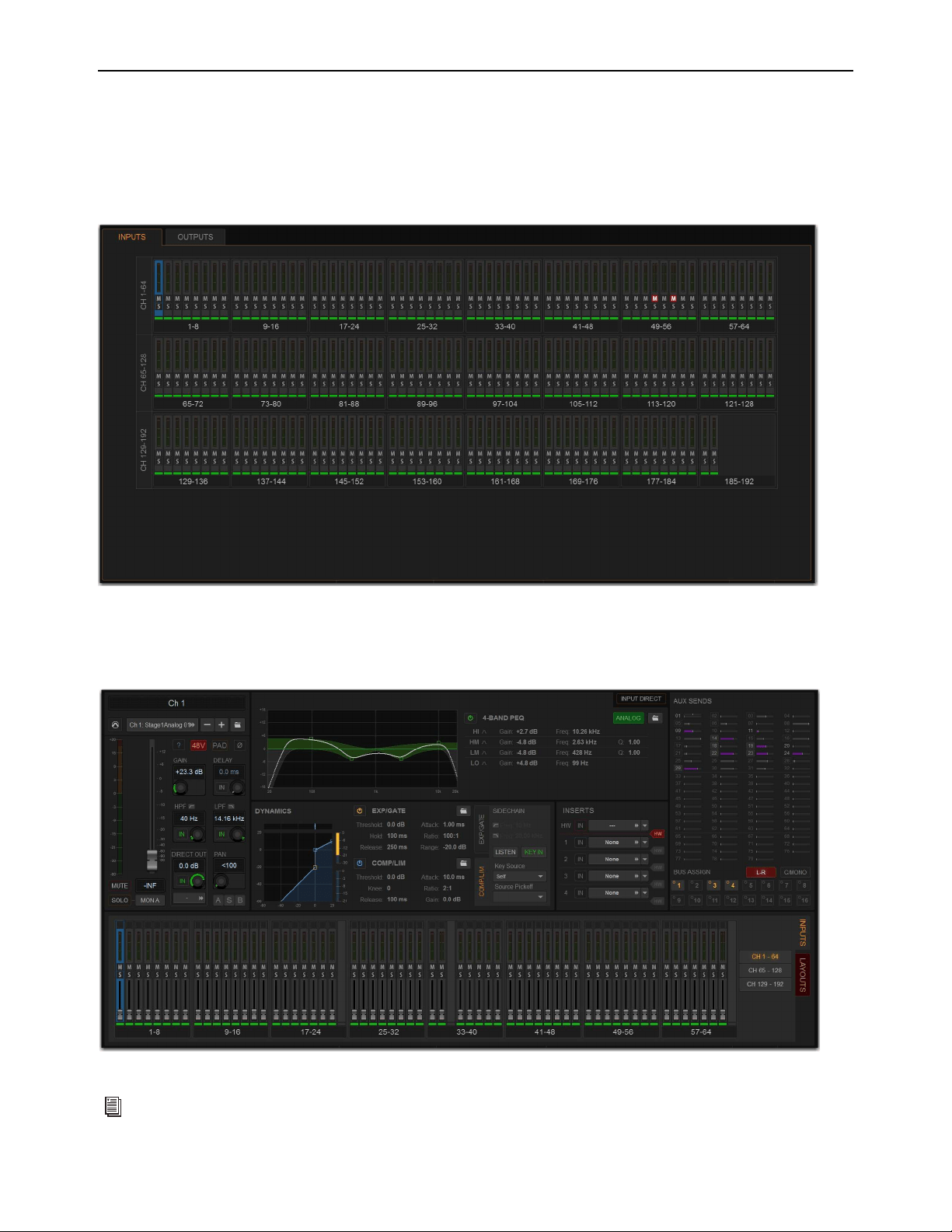
External VENUE Software Screen Overview 175
Overview of Software Pages
The software screen provides the following pages and tabs.
Overview
View meters, attention, mute, and solo channels.
Inputs and Outputs Pages
Attention channels, and view, name, configure, and adjust parameters for the currently attentioned channel.
Overview page
Inputs page
See
Overview, Inputs, and Outputs Pages.
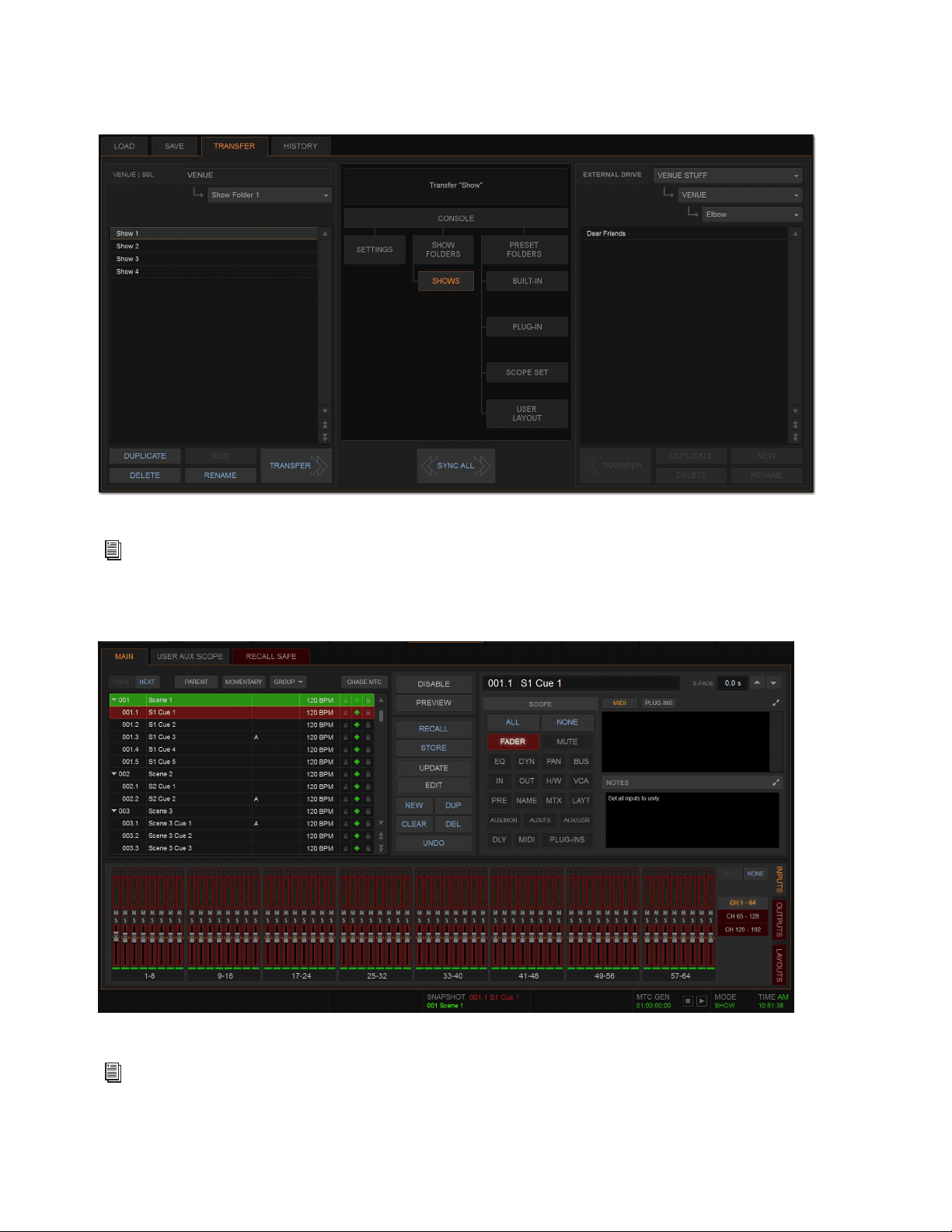
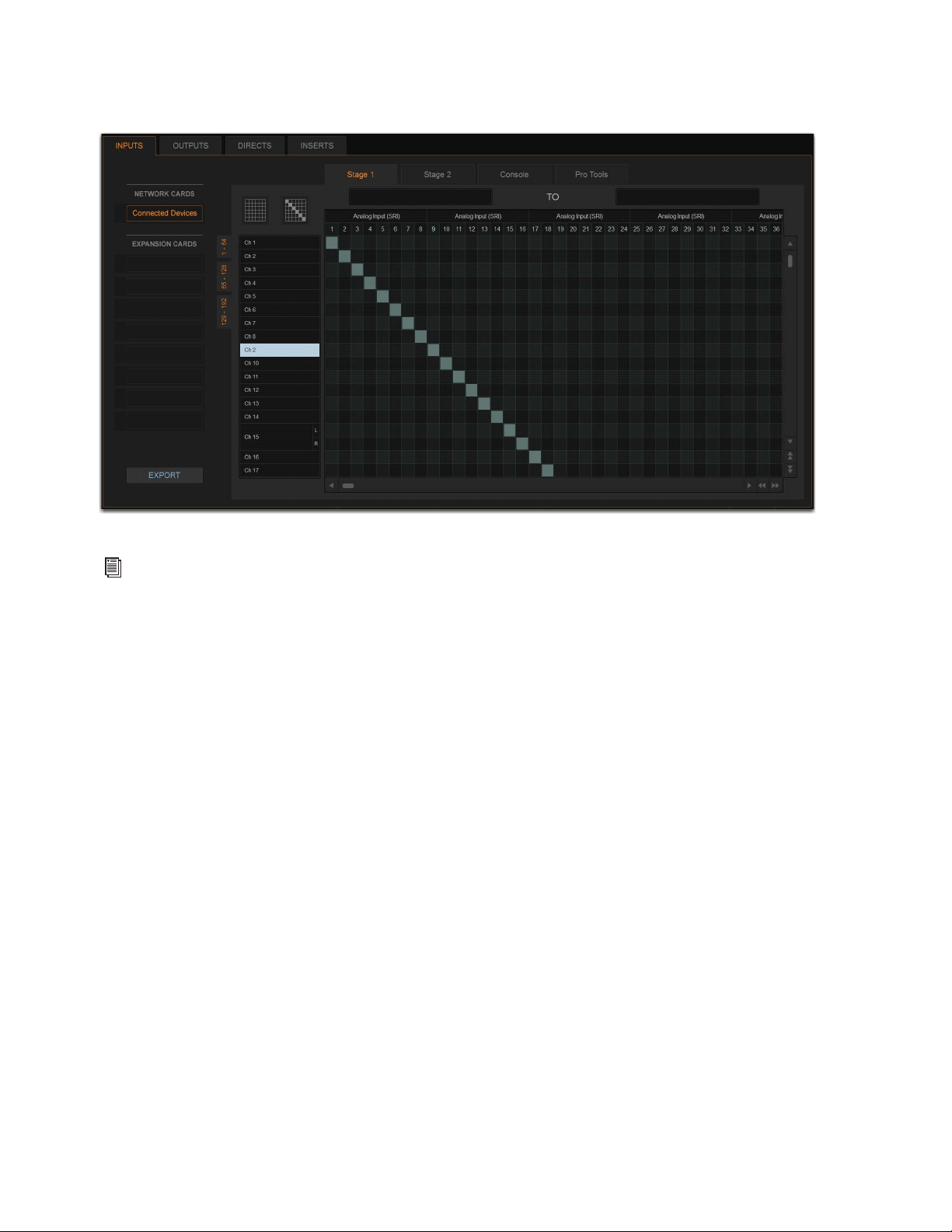
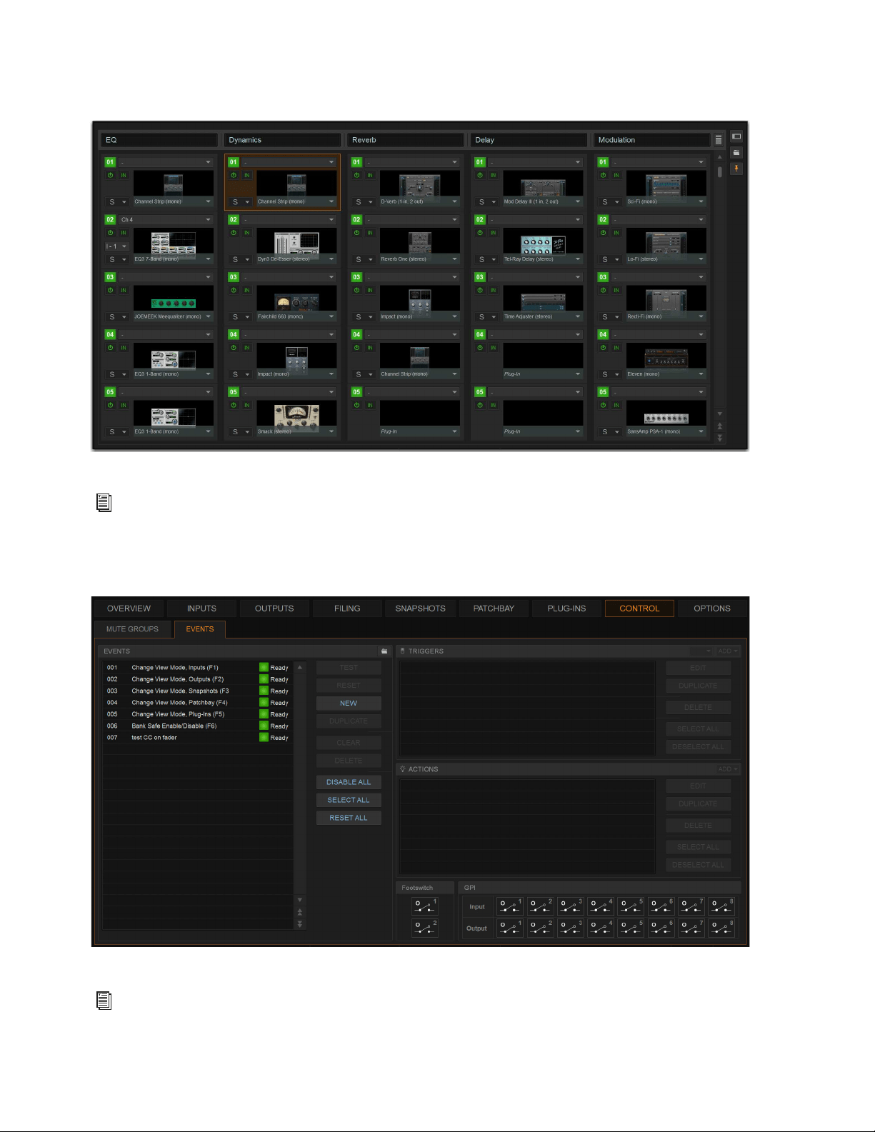
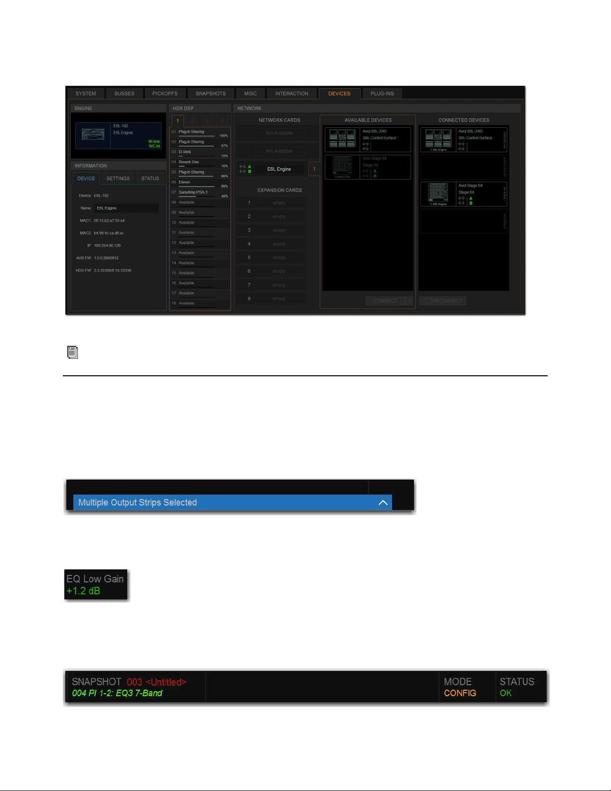
External VENUE Software Screen Overview 179
Options
Configure system, routing and metering options, set interaction, hardware and general preferences, and install plug-ins.
Banner Display
At the bottom of the external screen, a banner display shows message and alert dialogs, and system status information at all times.
Messages, alerts, and warning dialogs in the banner display alert you to certain operating conditions such as Multi-Select and
Multi-Assign modes (appearing in blue), system alerts (appearing in orange) and warning dialogs (appearing in red). You can select
the messages and alerts shown in the banner display to expand the message, letting you confirm (OK) or cancel the current mode,
and dismiss alerts and warning dialogs.
When adjusting a parameter, the banner display shows the value of the parameter (such as fader level or EQ band gain) as you make
changes to that parameter.
The banner display also shows snapshot information, the current operating mode (Show or Config mode), and system status infor-
mation such a plug-in rack status and word clock status. You can choose to show the current time in the Status area (see
System
Clock for more information).
Options page (Devices tab shown)
See
Options.
Banner display showing a message
Banner display showing the value of the currently adjusted parameter
Banner display showing snapshot information, current operating mode, and status

External VENUE Software Screen Overview 180
Type Text Search
Type Text search lets you use the keyboard for fast navigation to a channel, or to quickly go to a specific snapshot or event. You
can enter the first characters of a channel name or the absolute channel number to target that channel on the external screen, or in
Channel Control (see also Selecting Channels.)
To search for and select a channel by name:
1 Go to the Inputs, Outputs, or Patchbay page.
2 Type the first few letters, channel number, or full name of the channel. For example, type “s” to go to the first channel beginning
with the letter s (such as Snare).
3 Press the Tab key on your keyboard to cycle through and select any other channels beginning with that letter (such as Snare Top,
Snare Bottom, or Strings).
To search for and select a list item by name (or number):
1 Go to the Snapshots page, Filing page, or the Events tab of the Options page. Or, select a Presets window (built-in Dynamics or
EQ presets, Input Channel presets, or Scope Sets).
2 Type the first few letters or number of the desired item.
3 Press the Tab key on your keyboard to cycle through and select any other items that begin with the same letters.
Channel Numbers and Names
Channel numbers in VENUE are “absolute” channel numbers. Renaming changes the displayed name associated with each chan-
nel, but the absolute channel number remains fixed.
To search for and select a channel by absolute number:
Type a number on the keyboard to select the corresponding channel.
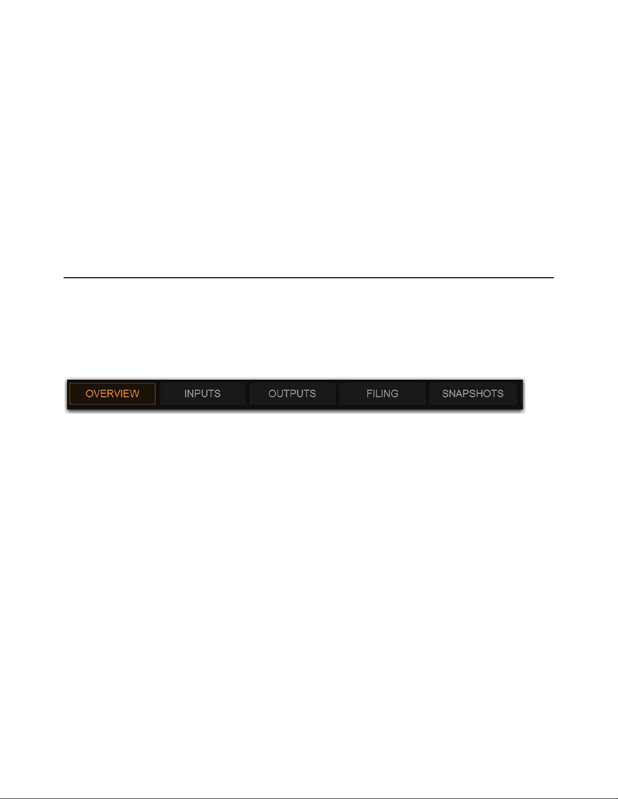
Overview, Inputs, and Outputs Pages 181
Overview, Inputs, and Outputs Pages
The Overview, Inputs, and Outputs pages of the external VENUE software screen show channel data for system input and output
processing channels, and let you adjust certain channel parameters, as follows:
Overview
Provides output meters for all system input or output channels, and lets you attention, solo, and mute channels. If using
an S6L-16C, the Universe view is a tab available in the Overview page. (On other control surfaces, Universe view is displayed on
the MTS.)
Inputs and Outputs
Show channel data for the currently attentioned channel, including virtual fader strips for up to 64 channels at
a time, and let you adjust many different channel parameters for the currently attentioned channel. The Inputs and Outputs pages
also let you perform tasks such as reordering input channels using drag-and-drop, copying and pasting channel settings, inserting
blank channel strips, and managing members of output channels.
Navigating the Overview, Inputs, Outputs Pages
To access the Overview, Inputs, or Outputs page, use the buttons at the top of the external screen, buttons on the MLM, or the key-
board.
To access the Overview page:
Select the Overview button, or press the F1 key on the keyboard.
To access the Inputs page:
1 Select the Inputs button.
2 Press the F1 Function switch on the MLM.
– or –
• Press the F2 key on the keyboard.
To access the Outputs page:
1 Select the Outputs button.
2 Press the F2 Function switch on the MLM.
– or –
• Press the F3 key on the keyboard.
Universe View
If using an S6L-16C, the Universe view is a tab available in the Overview page. On other control surfaces, Universe view is dis-
played on the MTS.
Overview page button selected
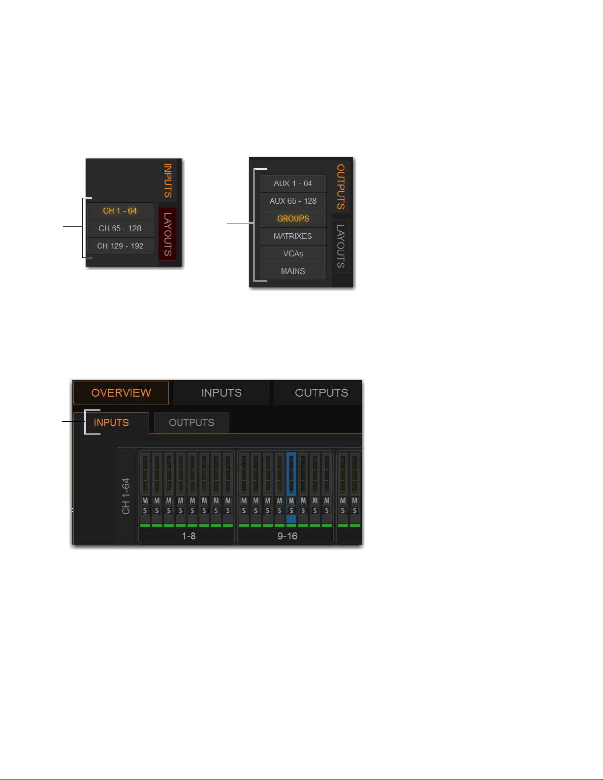
Overview, Inputs, and Outputs Pages 182
To access channels on the Inputs or Outputs page:
1 Go to the Inputs or Outputs page.
2 Select the Inputs or Outputs tab along the side of the fader strip section.
3 Do either of the following depending on the tab you selected:
• For inputs, select the button showing the channel range you want to access (CH 1–64, CH 65–128, or CH 129–192).
• For outputs, select the button showing the type of output channels you want to access (Aux x–xx, GROUPS, MATRIXES,
VCAs, or MAINS).
To access channels on the Overview page:
1 Go to the Overview page.
2 Select the Inputs or Outputs tab, under the Overview button, to access those respective channels on the Overview page.
Solo and mute are activated by clicking on the corresponding icon.
Input Channel Bank buttons (left) and Output Channel Type buttons (right)
Overview page Inputs and Outputs tabs (Inputs selected)
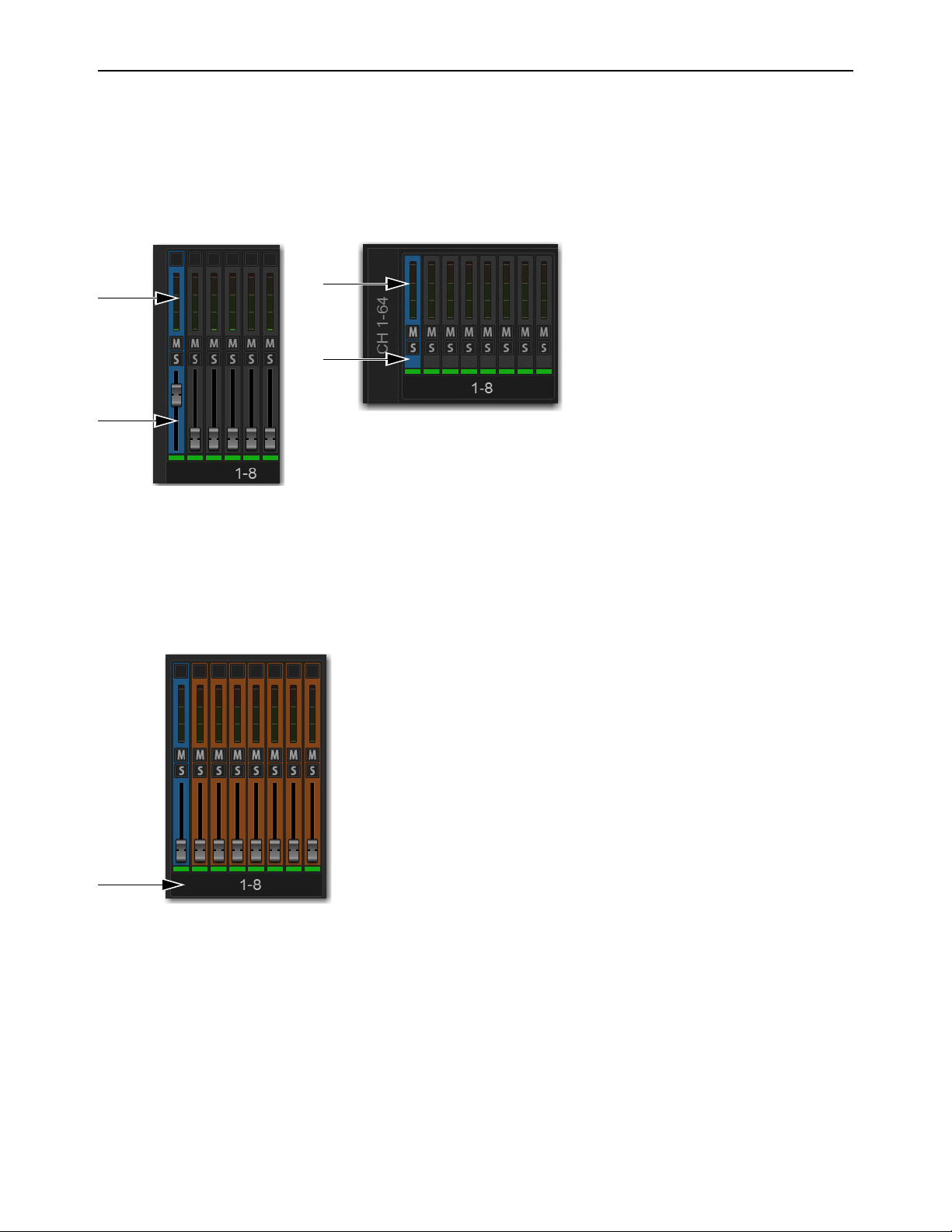
Overview, Inputs, and Outputs Pages 183
Attentioning Channels from the External Screen
You can attention channels from the Overview, Inputs, or Outputs page. When you attention channels from the external screen, the
channels are also attentioned on the channel strips and on the MTS (and vice-versa). By default, the Inputs or Outputs page shows
the attentioned channel’s parameters, which you can adjust on the external screen.
To attention a channel on-screen
Touch anywhere in the on-screen fader strip, except on the fader, mute, solo or safe buttons.
To attention multiple channels on-screen:
Press and hold the Multi-Select switch (or hold Shift on the keyboard) and touch the fader strips on-screen.
To select an 8-channel bank on-screen:
Touch the bank name (such as 1–8 or Aux 1–8) below the on-screen fader strips to select all the channels in that bank. Hold Shift
and touch to select additional banks or channels. One channel remains the attentioned channel, and lights blue.
To select all input channels or all output channels on-screen (Multi-Select):
Double-tap any bank name below the on-screen fader strips in the Input or Outputs screen. One channel remains the attentioned
channel, and lights blue.
To remove a channel from a selection:
Control-touch (or Fine-touch) a highlighted channel.
To exit a Multi-Selection:
Press the Cancel switch on the MLM, or the Cancel button in the on-screen banner display.
Touch in the indicated areas to attention a channel from the external screen fader strips (Inputs/Outputs page at left, Overview page at right)
Select the bank display to select multiple channels on-screen
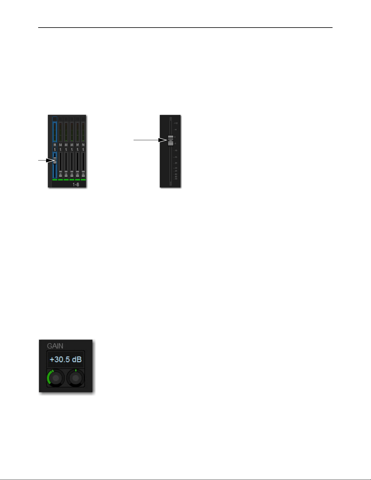
Overview, Inputs, and Outputs Pages 184
Adjusting Parameters on the External Screen
This section describes how to adjust channel parameters on the external screen. Control over the parameters described here are
common to input and output channels.
Adjusting Faders on the External Screen
You can move on-screen faders independently or in ganged fashion.
To adjust a single fader on-screen, do one of the following:
Touch, hold, and drag the fader of one of the attentioned channels.
To move multiple faders on-screen in ganged fashion:
1 Attention multiple channels on-screen.
2 Touch, hold, and drag the fader of one of the attentioned channels.
The faders on the selected channels will move in ganged fashion. Any offset between the faders is maintained until at least one of
the faders is minimized (moved to –INF) or maximized (set to +12dB).
To reset an entire channel to its default settings:
On-screen, touch and hold (right-click) the on-screen fader and choose Reset Ch <n>.
Adjusting Encoders on the External Screen
You can adjust on-screen encoders by dragging the encoder.
To adjust an on-screen encoder:
1 Touch an encoder so that it is highlighted.
2 Drag upwards to turn the encoder clockwise; drag downwards to turn the encoder counter-clockwise.
Drag a fader on-screen to adjust channel level
On screen encoders
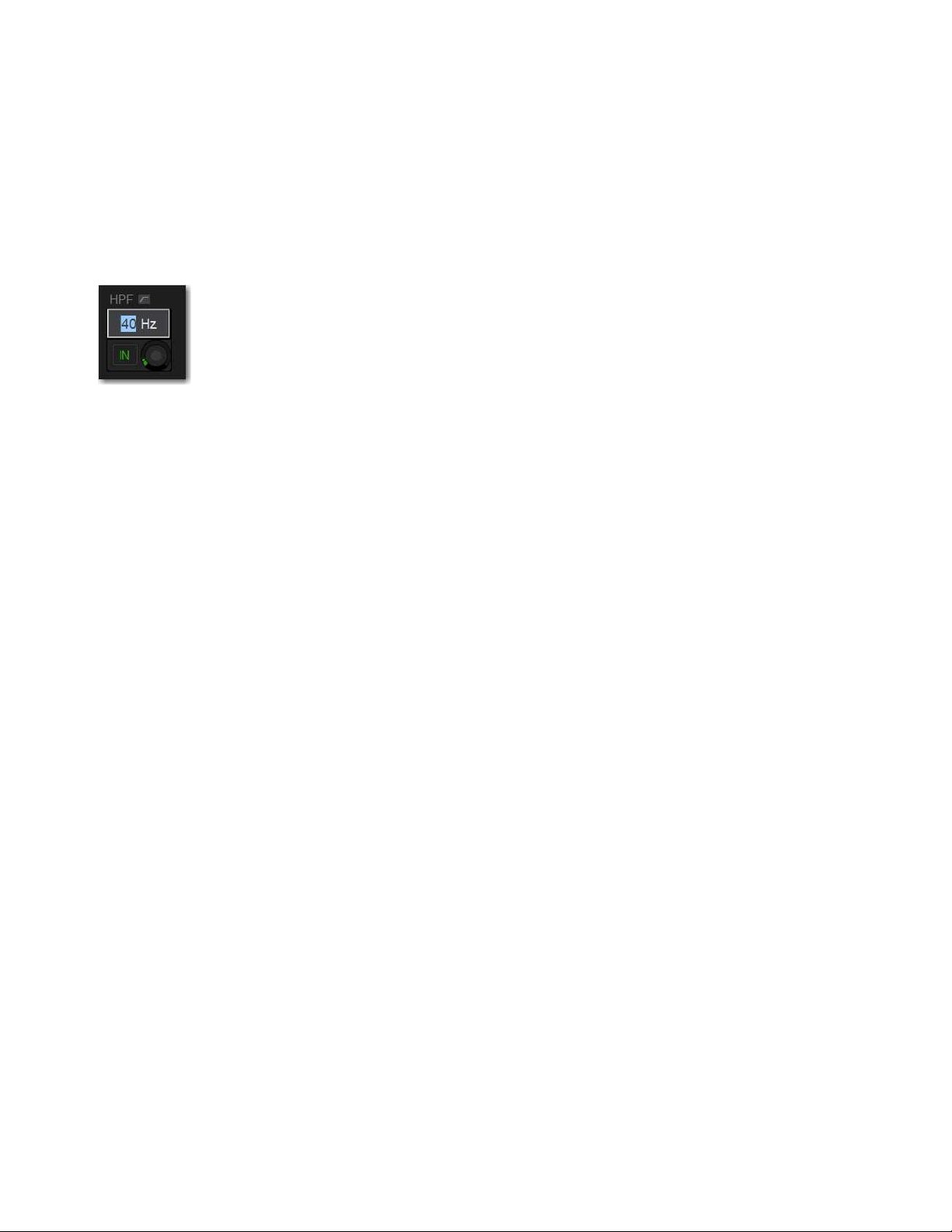
Overview, Inputs, and Outputs Pages 185
Adjusting Values on the External Screen
In addition to typing numeric values in text boxes, you can adjust parameter values and numeric option settings on-screen by drag-
ging directly over the corresponding text box, and by entering values using the keyboard.
To adjust a value on-screen by dragging:
1 Select the text box to highlight the value.
2 Drag up to increase the value; drag down to decrease the value.
– or –
• Type in a value using the keyboard, and press Enter.
Toggling Buttons on the External Screen
You can toggle on-screen buttons such as Solo and Mute by touching (selecting) the on-screen button.
To toggle an on-screen button:
Touch the button to toggle that parameter on/off. The button lights when the parameter is on.
Resetting Channels and Parameters from the External Screen
You can reset a single parameter, and reset an entire strip (including its I/O hardware patching) to default settings from the external
screen.
To reset an on-screen parameter to its default value, do one of the following:
Touch-and-hold (right-click) the control and choose Reset <parameter> to <default value>.
To reset all parameters on a channel:
1 Enable Config mode.
2 Go to the Inputs or Outputs page.
3 Touch-and-hold (right-click) the fader strip and choose Reset <channel name/number>.
Entering a parameter value on the external screen
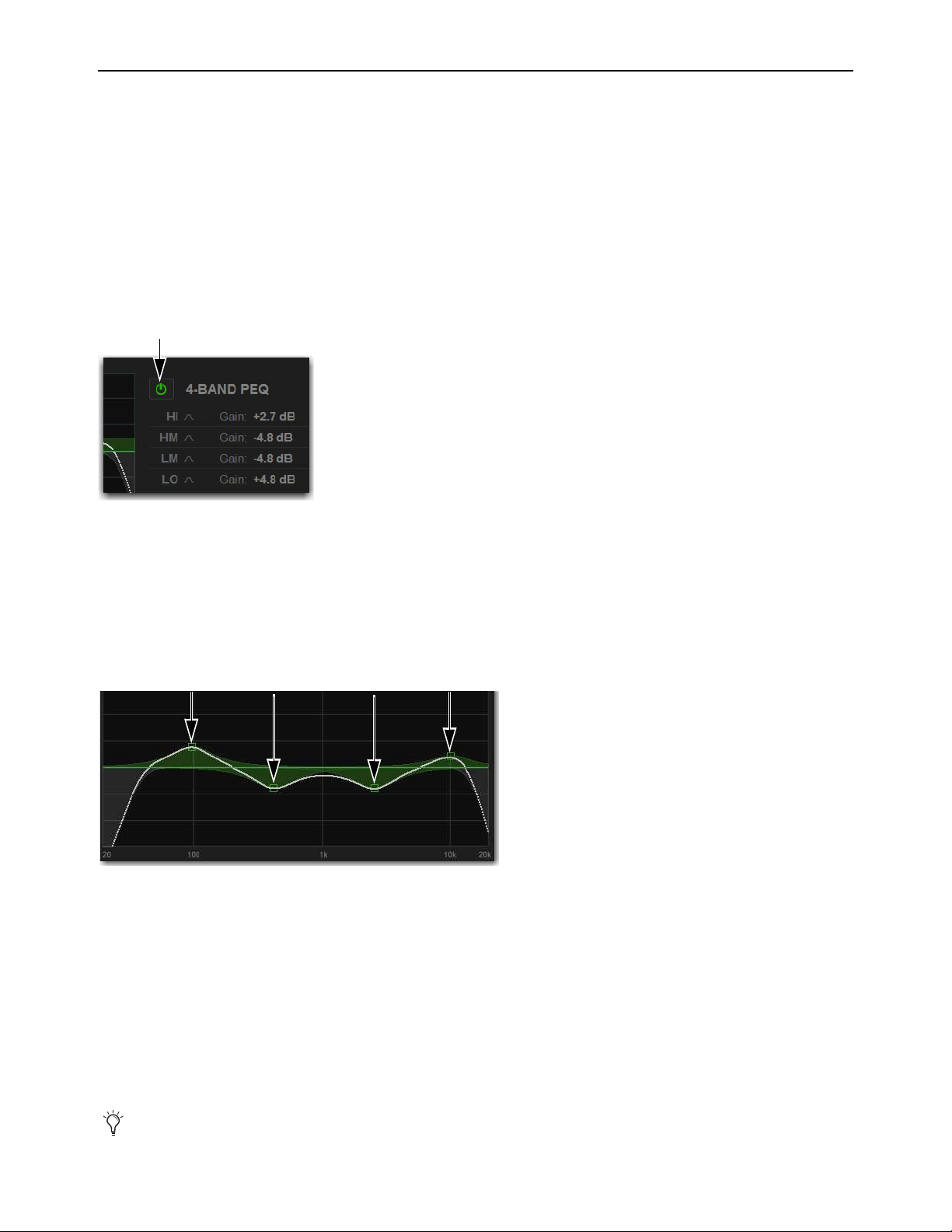
Overview, Inputs, and Outputs Pages 186
Working with EQ and Dynamics on the External Screen
You can adjust built in channel EQ, Graphic EQs (GEQs), and Dynamics on the Inputs and Outputs pages for the attentioned chan-
nel. You can also insert GEQs on the Outputs page. Input Direct, for input channels only, lets you bypass all EQ and Dynamics.
Adjusting Channel EQ
on the External Screen
You can toggle EQ on/off, adjust frequency and gain for any available EQ band of the built-in EQ, toggle Analog and Digital EQ
modes, and engage Input Direct.
To toggle EQ on/off:
1 Go to the Inputs or Outputs page and attention the desired channel.
2 Select the EQ in/out button. The EQ is in when the button lights.
To adjust EQ on the screen using the Graph display:
1 Go to the Inputs or Outputs page and attention the desired channel.
2 Select the EQ in/out button to put the EQ in circuit.
3 Drag the handles in the on-screen EQ graph display for each EQ band (Lo, Lo-Mid, Hi-Mid, or Hi), as follows:
• Drag a handle right or left to adjust EQ band frequency.
• Drag a handle up or down to adjust EQ band gain.
Analog and Digital EQ Modes
The Analog button on the Inputs and Outputs pages of the external screen toggles the built-in EQ between digital mode and analog
mode, on a per-channel basis, and is adjusted on-screen.
Digital Mode
Provides a standard digital parametric EQ. Frequency range of 20Hz to 20kHz and gain range of +/–18 dB are avail-
able on all bands. Hi and Lo bands can be Bell (default) or Shelf. Digital Q is expressed in Q factor terms in the range 10 (left, a
narrow band) to 0.1 (right, a wide band). Digital mode is the default EQ mode.
Analog Mode
Provides an EQ with a response modeled on that of an analog console renowned for its EQ section. Frequency range
is limited to match, and the outer bands provide shelving only. Analog Q is expressed in octaves of bandwidth in the range 0.1 (left,
a tenth of an octave) to 2 (right, two octaves.)
EQ in/out button
Drag the handles in the EQ graph display to adjust EQ
The HPF and LPF does not change when the EQ is switched between Digital and Analog mode.
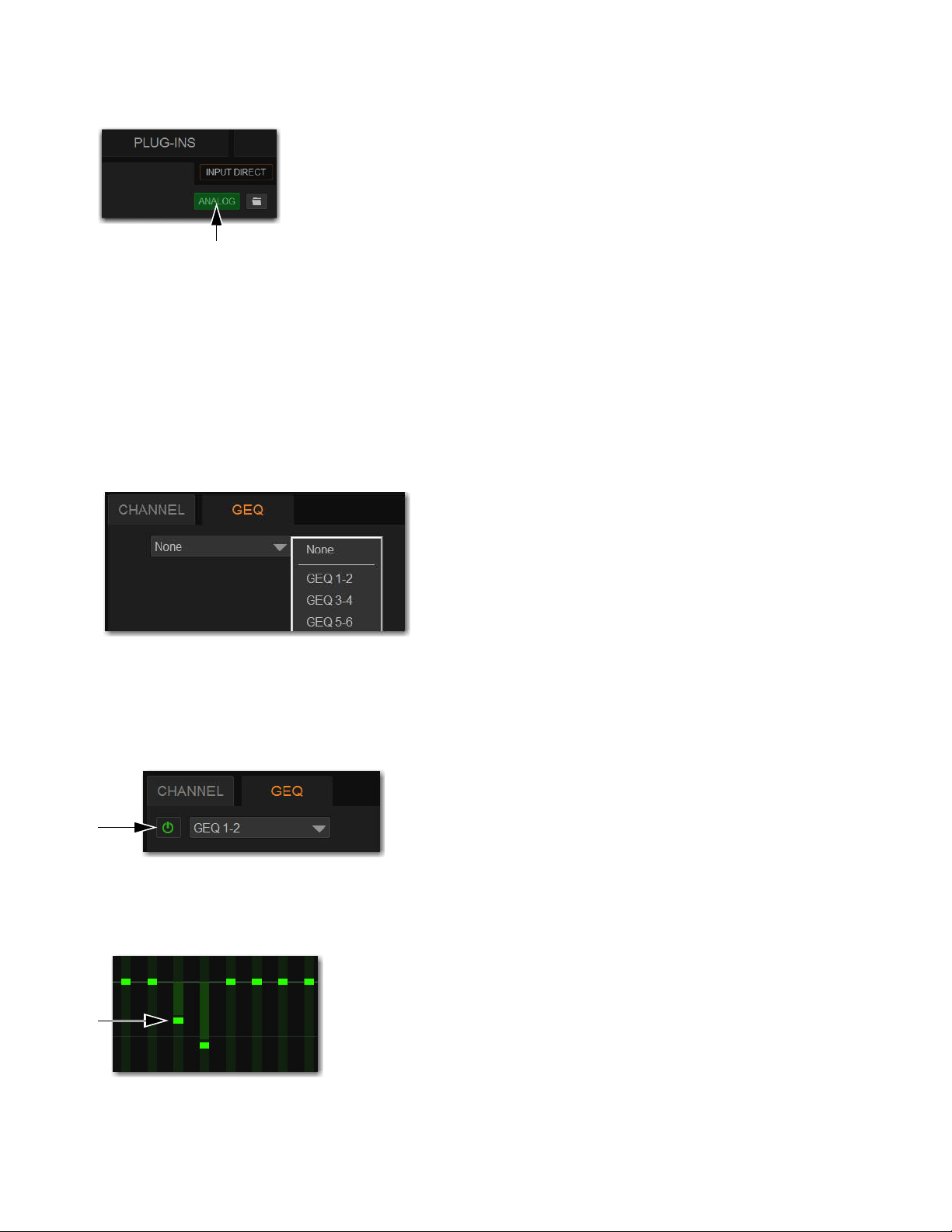
Overview, Inputs, and Outputs Pages 187
To toggle analog and digital EQ modes:
Select the Analog button. Analog lights when the EQ is in analog mode, and is unlit when in digital mode.
Adjusting Graphic EQ on the External Screen
S6L systems provide 32 built-in 31-band Graphic EQs (GEQs), which you can insert on the Mains, Group, Aux, and Matrix out-
puts. You can adjust GEQs on the external screen, as well as using the CKM (see Adjusting Graphic EQ on the Control Sur-
face).
To insert a Graphic EQ on an Output bus:
1 Go to the Outputs page and attention the output channel in which you want to insert the Graphic EQ.
2 Select the GEQ tab.
3 Select the Graphic EQ selector and choose an available mono or stereo Graphic EQ.
The entire Graphic EQ is displayed on-screen.
To toggle the GEQ in/out:
Select the GEQ in/out button. GEQ is in when the button lights.
To adjust GEQ on the external screen:
Drag the GEQ band sliders up or down to adjust band gain.
Analog/Digital EQ button (Analog enabled)
Selecting a Graphic EQ
GEQ in/out button
GEQ sliders

Overview, Inputs, and Outputs Pages 188
To adjust GEQ overall output level:
Drag the GEQ output level encoder, or select the level field and type in a value.
Adjusting Dynamics on the External Screen
To toggle Dynamics on/off:
1 Go to the Inputs or Outputs page and attention the desired channel.
2 Select the Exp/Gate and/or Comp/Lim in/out buttons, as desired. The processor is in when the button lights.
To adjust Dynamics on the screen using the Graph display:
1 Go to the Inputs or Outputs page and attention the desired channel.
2 Select the EQ in/out button to put the EQ in circuit.
3 Drag the handles in the on-screen Dynamics graph display as follows:
• To adjust Comp/Lim threshold and ratio, drag the blue handles.
• To adjust Exp/Gate threshold and ratio, drag the orange handles.
GEQ output level
Dynamics In/Out buttons
Comp/Lim handle (top, in blue) and Exp/Gate handle (bottom, in orange)
The Dynamics Graph does not support Fine adjust mode using the Fine switch.
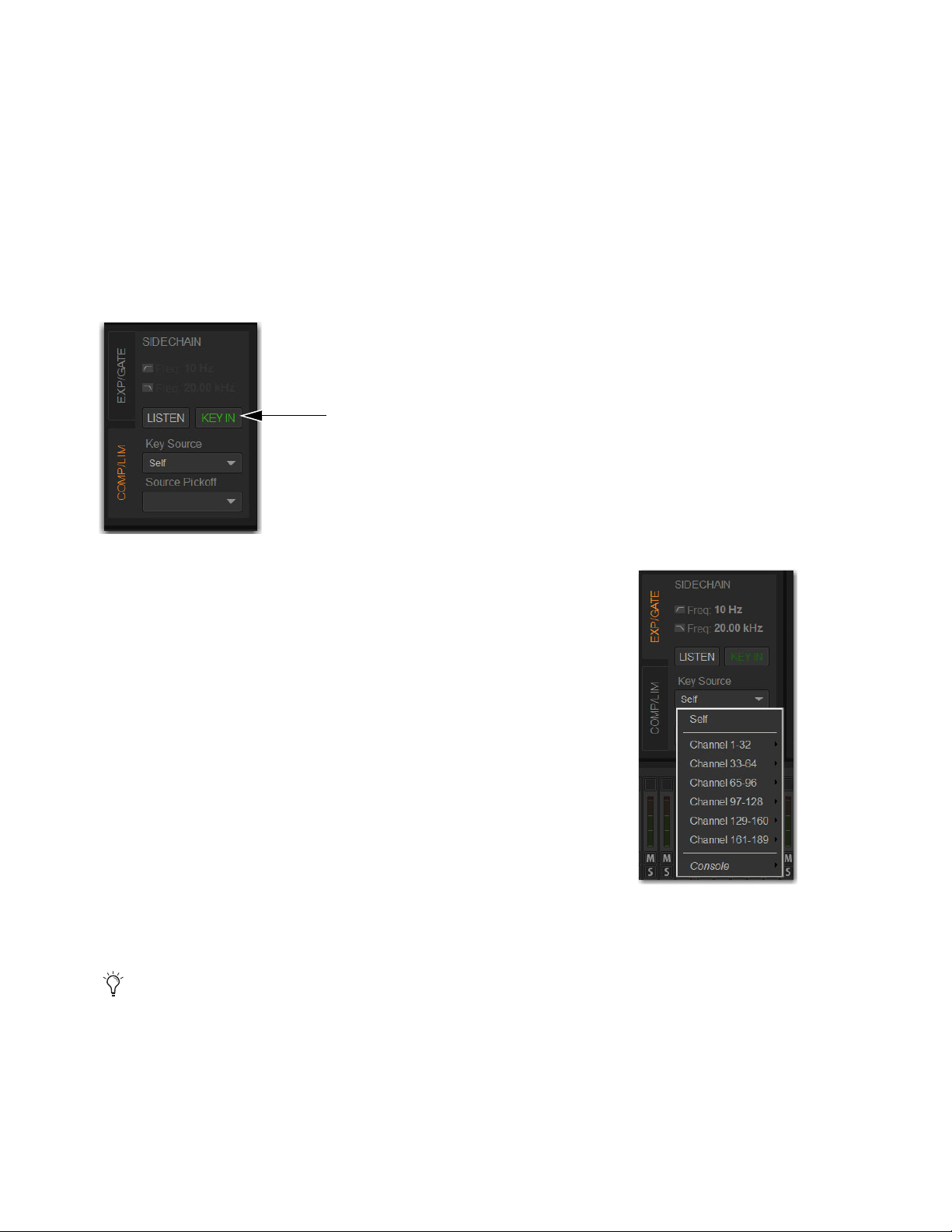
Overview, Inputs, and Outputs Pages 189
Sidechain
You can engage a built-in Dynamics processor sidechain, select the external key sidechain input, and engage key listen using the
external screen. For an overview of S6L system sidechain processing, see Sidechain.
Engaging the Sidechain
The sidechain must be engaged to enable both external key and EQ filter sidechain processing for the selected channel. The Key
In control can be toggled in or out of circuit from Channel Control or on-screen.
To toggle the side-chain in or out of circuit from the Inputs or Outputs page:
For Comp/Lim, select the COMP/LIM Sidechain tab, and then select the Key In button.
For Exp/Gate, select the EXP/GATE Sidechain tab, and then select the Key In button.
Selecting the External Key Sidechain Input
(Key Source)
The Key Source selectors lets you select the side-chain source for either dynamics processor
and its pickoff point. You can use any of the following as the key source for the Comp/Lim
and the Exp/Gate:
•Self
• Any input channel
• Console hardware inputs
• You can also specify the pickoff source for the key signal for input channels.
To select the key input for the sidechain:
1 Go to the Inputs or Outputs page and attention the desired channel.
2 Select the EXP/GATE Sidechain tab in the dynamics section to select the gate.
3 Select the Key Source selector and choose an available channel or bus.
To select a pickoff point for the key source signal:
Select the Source Pickoff selector and choose one of the following pickoff sources for the selected key signal: Top of Channel,
Insert Return or Pre-Fader.
Key In button
Key Filters are engaged and adjusted using the CKM in Channel Control mode. See
Using Sidechain EQ Filters.
Choosing a Key Source
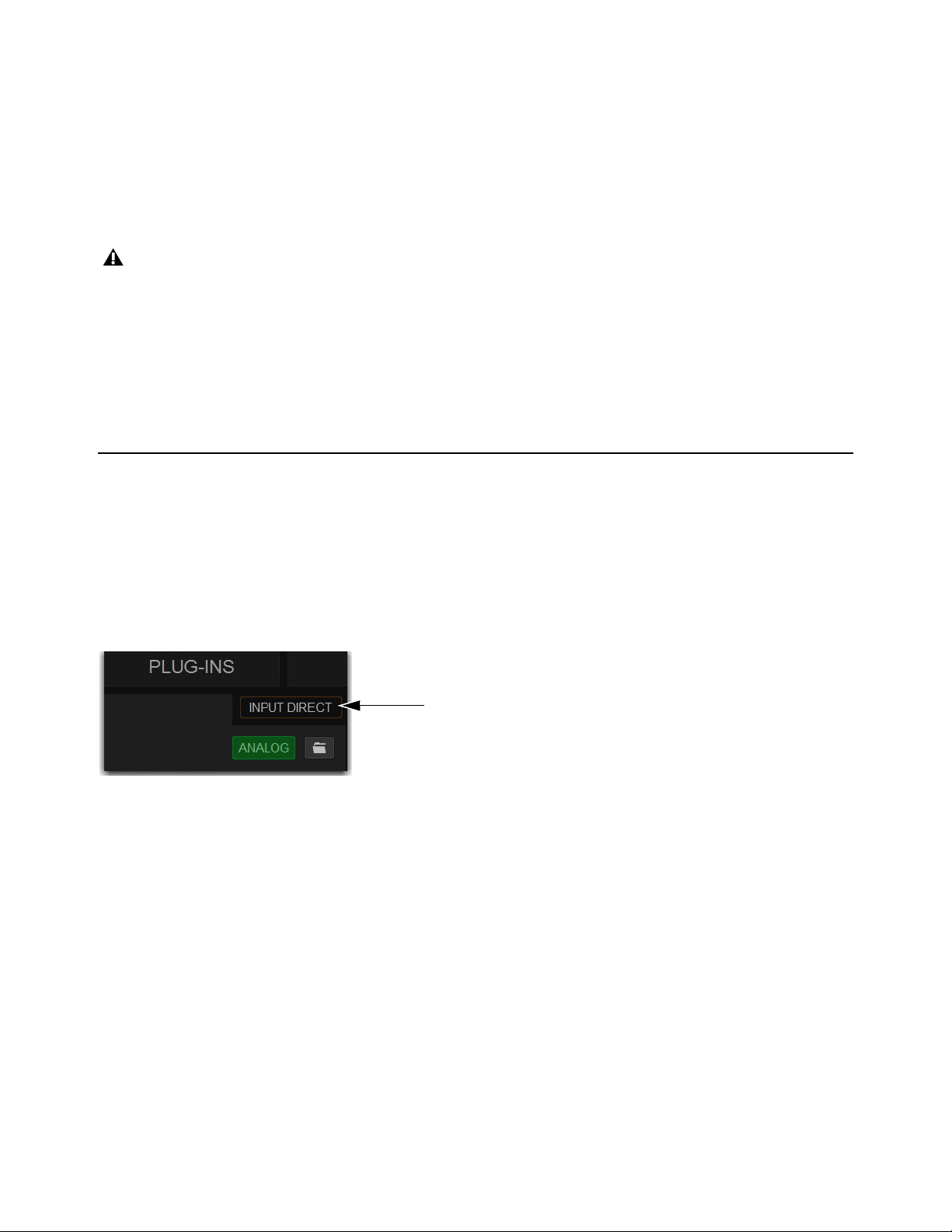
Overview, Inputs, and Outputs Pages 190
Key Listen
The Key Listen button toggles the key onto the Solo bus, replacing the signal there. This happens regardless of whether the key is
the channel signal or the external key, or whether it has been side-chain filtered.
Key Listen always overrides all other signals on the Solo bus. If soloed channels are already on the Solo bus, they are suppressed
until Key Listen is cleared. If additional channels are soloed while Key Listen is on, they will be added but suppressed.
The Key Listen solo is also exclusive to itself; pressing Key Listen on a different processor or channel turns off the previous Key
Listen and the new Key Listen takes over.
To engage Key Listen:
Select the Listen button in the on-screen Exp/Gate controls.
To disengage Key Listen:
Select Listen again. The Solo bus reverts to its previous signal (soloed channels, or none). You can also press Solo Clear once
to turn off any currently engaged Key Listen button. Press Solo Clear a second time to clear channel solos, if any.
Input Direct
Input Direct lets you completely bypass the built-in dynamics and EQ processing, and all inserts on input channels. This mode
routes the input signal directly from the Top of Channel pickoff to the channel fader.
To bypass all processing on an input channel:
1 Go to the Inputs or Outputs page and attention the desired channel.
2 Select the Input Direct button in the EQ section. All built-in channel EQ and Dynamics are bypassed, and the button flashes to
indicate Input Direct mode is active.
Key Listen on a dynamics plug-in does not route the signal to the solo bus, but to the plug-in output. Use caution when using the
Key Listen with a plug-in dynamics processor.
Input Direct button
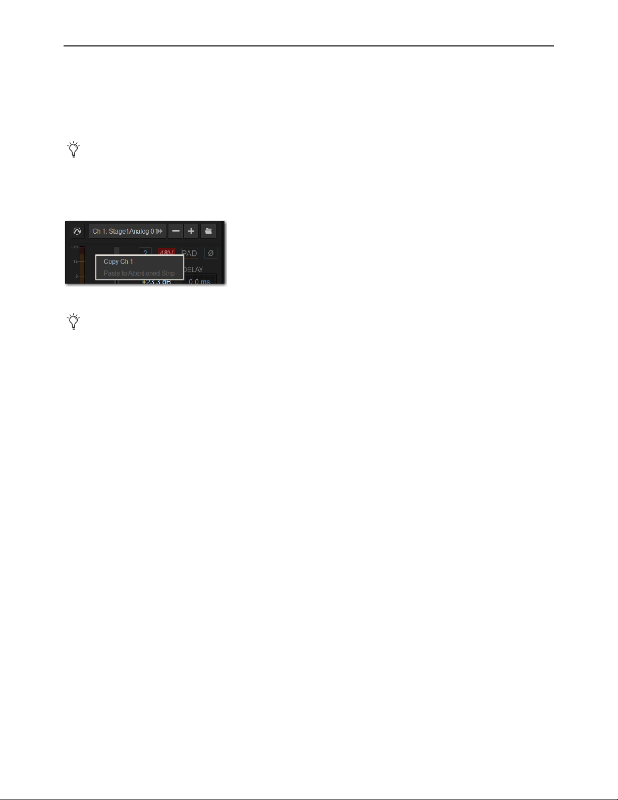
Overview, Inputs, and Outputs Pages 191
Copying and Pasting Settings
Copying and Pasting Channel Settings
You can copy channel settings in their entirety from one channel and paste them to one or more channels from the Inputs and Out-
puts pages. Using the Events list, Copy and Paste can be assigned to any Function switch on the console. For more information, see
Events.
To copy and paste channel settings on-screen:
1 Go to the Inputs or Outputs page and attention the channel whose parameters you want to copy.
2 Touch-and-hold (right-click) within the upper channel display and choose Copy.
3 Attention one or more destination channels. You can only paste to attentioned/multi-selected channels.
4 Touch-and-hold (right-click) on the lower fader strip on-screen, or on any non-control area of the destination channel, and
choose Paste to Selected Strip(s). The status displays shows a message confirming the operation.
Parameters and Channel Types
Input channels can only be copied or pasted to other Input channels. Output channels can only be copied or pasted to other channels
of the same type (such as Aux, Group, or Matrix). When pasting channel settings:
• Settings common to the source and destination channel are always pasted.
• Copied settings with no corresponding parameter in the destination channel are ignored.
• Settings in the destination channel with no corresponding parameters are left unchanged.
Copying and Pasting Mono and Stereo Channel Settings
You can copy a mono channel and paste its settings to one or more stereo channels. Mono settings are applied equally to the left
and right channels of the stereo destination. The stereo destination channel retains its current balance and width settings.
You can also copy a stereo channel and paste its settings to one or more mono channels. The left channel settings of the stereo
source are applied to the mono channel(s). The mono destination channel retains its current pan setting.
You can also store and load settings as Input Channel Presets. For information, see
Input Channel Presets.
Channel Copy/Paste pop-up menu
You do not need to select the channel before copying its settings on-screen.

Overview, Inputs, and Outputs Pages 192
Settings Excluded from Copy and Paste
Input Channels
The following Input channel parameters are not copied or pasted (the current settings of the destination channels
are retained):
• Patchbay assignments, including Direct Outs
• Channel Name
• Hardware and software insert (plug-ins) assignments and in/out state.
Output Channels
The following Output channel parameters are not copied or pasted (the current settings of the destination chan-
nels are retained):
• Patchbay assignments, including Direct Outs
• Channel Name
• Hardware and software insert (plug-in) assignments and in/out status
• GEQ settings
• Output membership (the assignment of channels to an Aux, Group VCA, or Matrix).
Copying and Pasting EQ Settings
Built-in channel and Graphic EQ settings can be copied and pasted between channels. EQ presets can also be saved and loaded to
archive and transfer settings.
To copy and paste an EQ setting:
1 Go to the Inputs or Outputs page and attention the channel whose parameters you want to copy.
2 Do one of the following:
• To copy a channel EQ setting, touch-and-hold (right-click) the on-screen EQ section or EQ graph (not on an encoder) and
choose
Copy EQ Settings.
– or –
• To copy a Graphic EQ setting, touch-and-hold (right-click) the graphic EQ display (not on a fader) and choose Copy GEQ
Settings.
3 Attention one or more destination channels. You can only paste to attentioned/multi-selected channels.
4 Do one of the following:
• To paste a channel EQ setting, touch-and-hold (right-click) in the new channel’s EQ section or graph and choose Paste EQ
Settings. All EQ settings, including HPF settings, are copied to the new channel.
– or –
• To paste a Graphic EQ setting, touch-and-hold (right-click) in the new channel’s Graphic EQ section and choose Paste GEQ
Settings.
To copy GEQ settings, use the copy/paste GEQ shortcut or use GEQ Presets. Use the Replace with Mix (members) From com-
mand to replace output membership for an Aux, Group, VCA, or Matrix.
EQ Reset/Copy/Paste pop-up menu
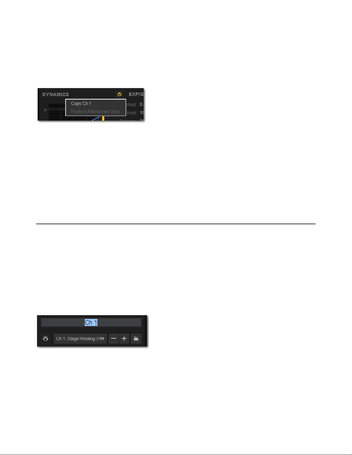
Overview, Inputs, and Outputs Pages 193
Copying and Pasting Dynamics Settings
Built-in dynamics settings can be copied and pasted between channels.
To copy and paste dynamics settings:
1 Go to the Inputs or Outputs page and attention the channel whose parameters you want to copy.
2 Touch-and-hold (right-click) anywhere in the Comp/Lim or Exp/Gate (input channels only) areas of the on-screen dynamics sec-
tion and choose Copy <channel number/name> Settings.
3 Attention one or more destination channels. You can only paste to attentioned/multi-selected channels
4 Touch-and-hold (right-click) in the Comp/Lim or Exp/Gate areas of the on-screen dynamics section and choose Paste
Comp/Lim Settings or Paste Exp/Gate Settings.
To copy and paste all of a channel’s built-in dynamics settings:
1 Go to the Inputs or Outputs page and attention the channel whose parameters you want to copy.
2 Touch-and-hold (right-click) in the on-screen Dynamics Graph and choose Copy Dynamics Settings.
3 Attention one or more destination channels. You can only paste to attentioned/multi-selected channels
4 Touch-and-hold (right-click) in the on-screen Dynamics Graph of the new channel and choose Paste Dynamics Settings.
Configuring Channels on the External Screen
Naming Channels
You can name channels from the Inputs and Outputs pages. Channel names can be up to 32 characters in length. When displayed
on the control surface, names are abbreviated to fit the display.
To change the name of a channel:
1 Go to the Inputs or Outputs page.
2 Attention the channel whose name you want to change.
3 Double-tap the channel name.
4 Type a new name and press Enter on the computer keyboard.
Dynamics Copy/Paste pop-up menu
Changing the name of an Input Channel on the Inputs page
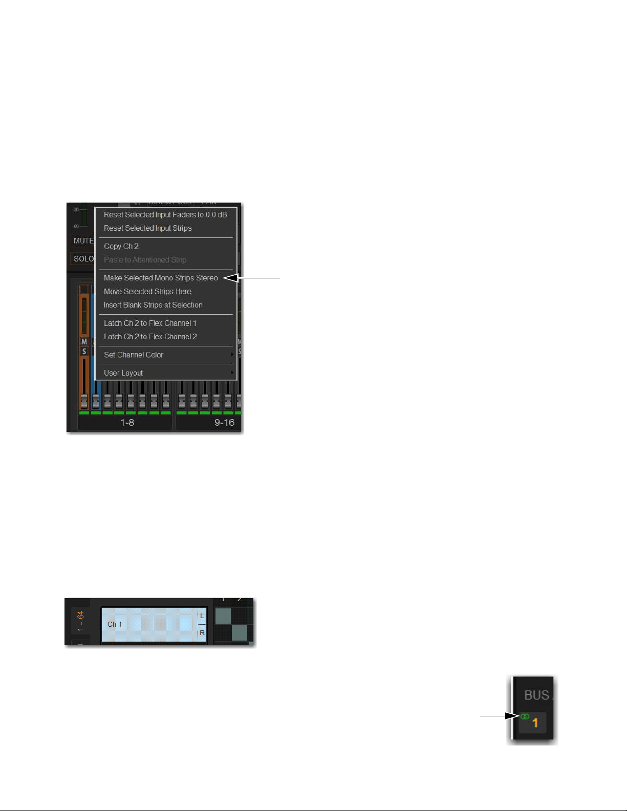
Overview, Inputs, and Outputs Pages 194
Make Selected Mono Strips Stereo/Make Selected Stereo Strip Mono
You can combine pairs of mono channels to make stereo channels, whose left and right sides are then controlled by a single channel
strip on the S6L control surface and on the fader strips on the external screen. This can be useful for creating effects returns or play-
back channels, for example. Input and output channels can be combined into stereo channels, except VCA and the Mains. You can
also split stereo channels back into mono channels
To combine two mono input channels into a single stereo channel:
1 Put the system into Config mode.
2 Multi-Select two channels.
3 Touch-and-hold (right-click) either of the selected mono channels on-screen and choose Make Selected Mono Strips Stereo.
Each selected channel is combined with the next-highest selected channel, even if the selected channels are not consecutive.
For input channels, blank strips are created and inserted where necessary to maintain channel layout in that bank.
For output channels, no blank strips are created or inserted, and channels in the layout in that bank are shuffled to the left, in-
cluding the corresponding Aux Sends.
Parameter values from the left most channel of each pair are applied to both channels
The pan control becomes a Balance/Width control.
Combined channels are shown in the Patchbay as left and right sides of the channel name. Mains and VCAs cannot be combined
or split.
In the Options > Buses page for Stereo Auxes, and the Bus Assign section for stereo Groups, stereo status
of a bus is indicated by two interlocking green circles.
Two mono inputs about to be combined into one stereo channel
Stereo Input Channel on the Input tab of the Patchbay

Overview, Inputs, and Outputs Pages 195
To split a stereo channel into two mono channels:
1 Put the system into Config mode.
2 Attention the stereo channel you want to split.
3 Touch-and-hold (right-click) the attentioned channel and choose Split Selected Stereo Strip to Mono.
The stereo channel is split, placing the channels next to each other on the control surface and in the Patchbay. Delete blank strips
manually to maintain channel layout, if necessary.
Move Selected Strip
You can move an attentioned Input, Aux, Group, or Matrix strip from its current position to a new location. When you move a chan-
nel using Move Selected Strip, other channels are moved (and renumbered) lower or higher to accommodate the moved channel.
To move a Channel strip:
1 Put the system in Config mode.
2 Go to the Inputs or Outputs > Auxes, Groups, or Matrixes page and attention the channel whose parameters you want to move.
3 On-screen, touch-and-hold (right-click) on the destination strip (where you want to move the attentioned channel).
4 Choose Move Selected Strip Here from the pop-up menu. The channel strip is moved before the destination strip.
Inserting Blank Strips
(Input Channels Only)
The Insert Blank Strip command lets you insert one or more blank (or “spacer”) strips anywhere among your input channels. In ad-
dition, blank strips are automatically inserted when you use the Make Stereo command to convert two mono input channels into a
single stereo channel, preserving the channel layout.
Blank strips are strictly placeholders (no audio or any type or processing take place), and therefore consume no additional process-
ing overhead or DSP resources. Use blank strips to create obvious divisions between groups of instruments, or to optimize the bank
placement of inputs on the console. Blank strips are saved and loaded as part of the Show file.
Blank Strips on the Control Surface
A blank strip has no LCD channel name display, and all of its physical controls and indicators are inactive. Blank strip faders are
set to the bottom (–inf) position and always revert to this position if moved.
Blank Strips On-Screen
On the MTS Universe view, blank strips appear as blank Channel Tiles. On the external screen, blank strips appear as a simple gray
strip with no fader, buttons or meter. Insert and remove blank strips on the external screen.
Snapshots cannot store and recall custom console channel positions.
You can also drag and drop channels. See
Reordering Channels Using Drag and Drop.
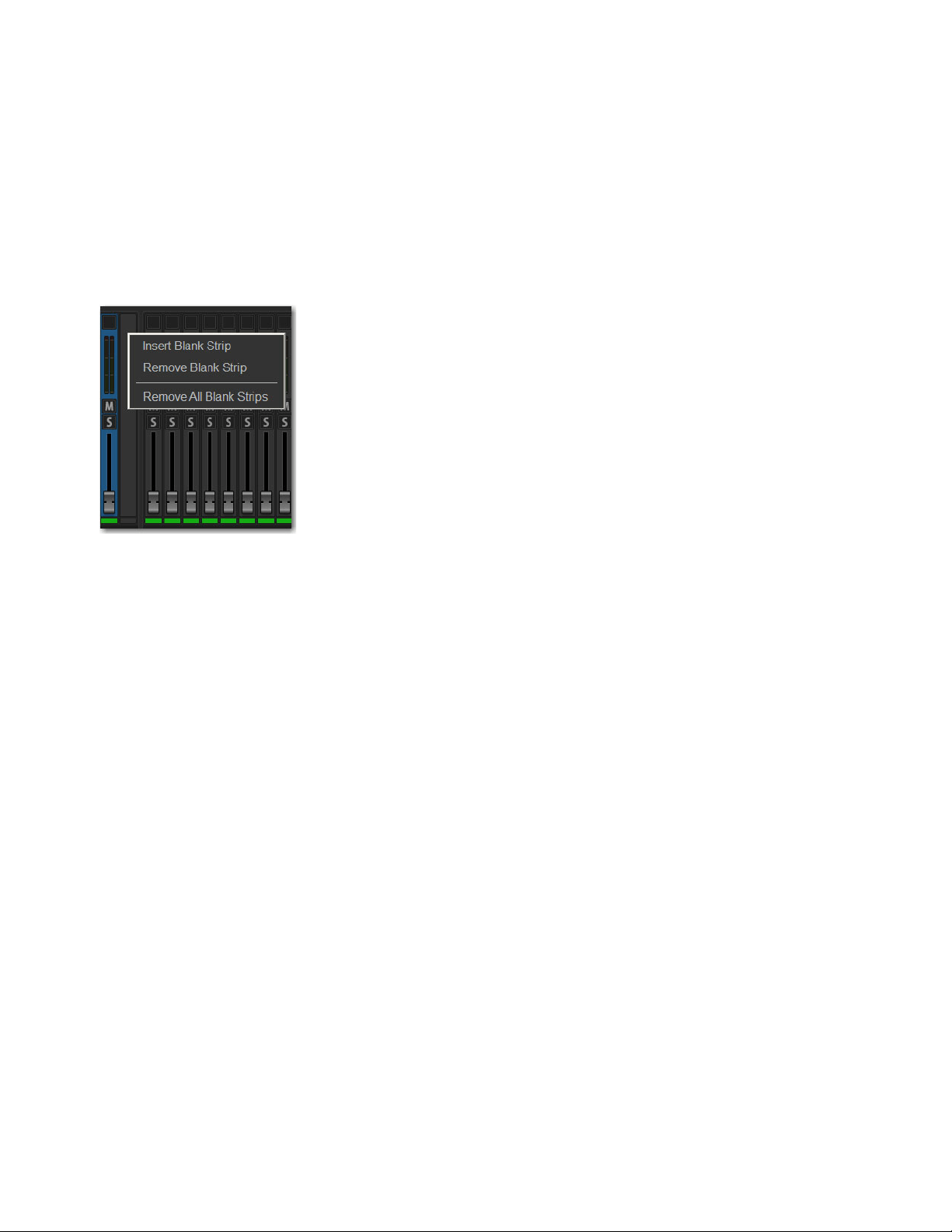
Overview, Inputs, and Outputs Pages 196
Adding Blank Strips
Blank strips can be inserted manually, and are also created automatically when you use the Make Stereo command. You can also
insert multiple blank strips.
To manually add a blank strip:
1 Enable Config mode.
2 Go to the Inputs or Outputs page.
3 Touch-and-hold (right-click) an input channel strip (or a blank strip) at the location where you want to insert a blank strip and
choose Insert Blank Strip. For example, if you want to have a blank strip at channel strip 16, touch-and-hold (right-click) on
channel 16.
All channels to the right of the insertion point are shuffled one position to the right.
To insert multiple blank strips:
1 Enable Config mode.
2 Create a multi-selection of channels.
3 Touch-and-hold (right-click) on one of the selected channels and choose Insert Blank Strips at Selection.
A blank strip is inserted in place of each selected channel strip, shifting all channels accordingly and maintaining the multi-selec-
tion.
Blank Strips When Using Make and Split Stereo
VENUE automatically creates blank strips when you use the Make Stereo command in order to preserve the current channel layout.
Similarly, blank strips may be automatically removed when you use the Split Stereo command to revert a stereo strip to its two con-
tributing mono channels.
Make Stereo
A blank strip is automatically inserted at the location previously occupied by the right-side channel of the
newly-formed stereo pair. There is no shuffling of the remaining input channels as a result of this operation.
Split Stereo
The behavior when splitting a stereo strip into two mono strips is as follows:
• If a blank strip is located immediately adjacent to the (previously) stereo channel, the right channel of the stereo pair occupies
this position and the blank strip is automatically removed. No other channels shuffle.
• If no blank strip is located immediately adjacent to the (previously) stereo channel, all channels to the right of the split point
shuffle one position to the right and the right channel of the stereo pair is inserted.
Blank strip menu
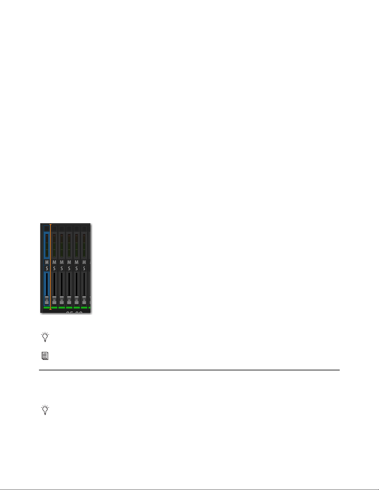
Overview, Inputs, and Outputs Pages 197
Removing Blank Strips
To remove a blank strip:
Touch-and-hold (right-click) the blank strip you wish to remove and choose Remove Blank Strip.
To remove all blank strips:
Touch-and-hold (right-click) any blank strip and choose Remove All Blank Strips. Blank strips are removed and all channels to
the right are shuffled to the left.
Reordering Channels Using Drag and Drop
You can reorder Input channels, Auxes, Groups, and Matrixes by dragging and dropping on-screen. You can reorder any channels
in a User Layout, including output channels. When you reorder channels, the location of the channel changes on the control surface
and on-screen. The original hardware input for the channel remains the same, and all other channel parameters are preserved.
To reorder a channel:
1 Put the system into Config mode.
2 Go to the appropriate page on the external screen, depending on where you want to reorder channels:
• To reorder input channels, go to the Inputs page and select the Inputs tab.
• To reorder output channels, go to the Outputs page and select the Aux, Groups, or Matrixes tab.
• To reorder channels in a User Layout, go to the Inputs or Outputs page, and then select the Layouts tab.
3 Attention the channel you want to move.
4 Touch-and-hold the channel then drag it to the desired location., denoted by the orange line, then release your finger.
Inserting Plug-Ins on Channels
You can insert plug-ins on input and output channels directly from the Inputs or Outputs page, or from the Plug-In Rack. For com-
plete information on routing and inserting plug-ins, see Routing Plug-Ins.
Reordering an Input channel using drag and drop
You can select and reorder multiple input channel strips. Shift-Touch multiple fader strips and drag them to the new location.
Channels can also be moved using the Move Selected Strip command. See
Move Selected Strip.
You can also insert outboard hardware. See Hardware Inserts.
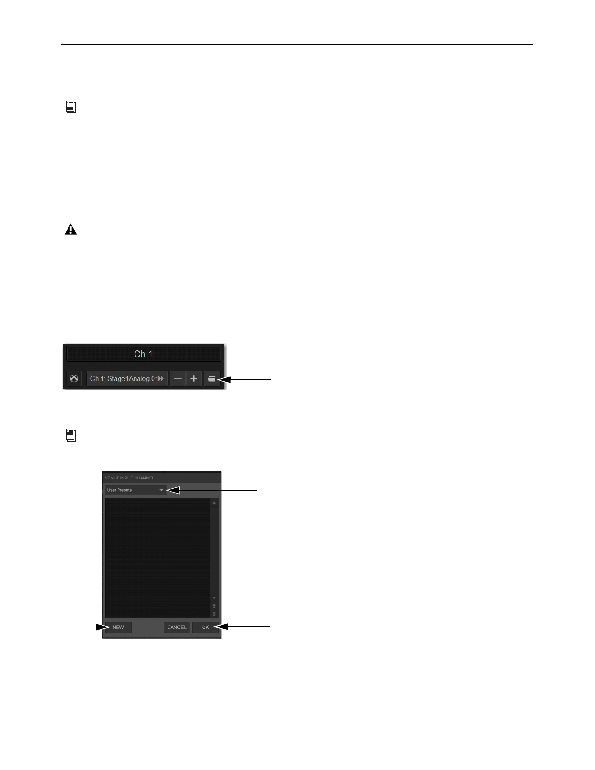
Overview, Inputs, and Outputs Pages 198
Input Channel, EQ, and Dynamics Presets
You can use Presets to store and load input channel settings, built-in channel EQ and GEQ settings, and Dynamics settings from
the Inputs and Outputs pages.
Input Channel Presets
You can store and load input channel configurations as Input Channel Presets. Input Channel Presets can be previewed, loaded and
transferred just like other Preset files, letting you quickly configure channels from among a library of favorite setups.
When an Input Channel is stored or recalled as a preset, all parameters are affected except the following:
• Patchbay assignments, including Direct Outs
• Hardware and software insert (plug-in) assignments and in/out state.
To store a channel as an Input Channel Preset:
1 Adjust parameters as needed.
2 Go to the Inputs or Outputs page.
3 Attention the channel whose settings you want to save or load.
4 Under the channel name, select the Presets Folder icon to open the Input Channel Presets window.
5 Choose a Presets folder from the Folder pop-up menu.
6 Select New, enter a name for the Preset, then select OK, or choose Cancel to exit the Presets folder without making changes.
For information about managing Presets files and folders, see
Working with Presets
Choosing a preset automatically loads the saved settings into the attentioned channel. Depending on the stored settings this may
dramatically change channel level and signal routing. Use caution when previewing Input Channel Presets with a live source.
Channel Presets icon in the Inputs page
See
Creating Preset Folders to create your own Presets folder so they show up in a Presets Folder pop-up menus.
Input Channel Presets window showing the Folder pop-up menu (top) and the New and OK buttons (bottom)
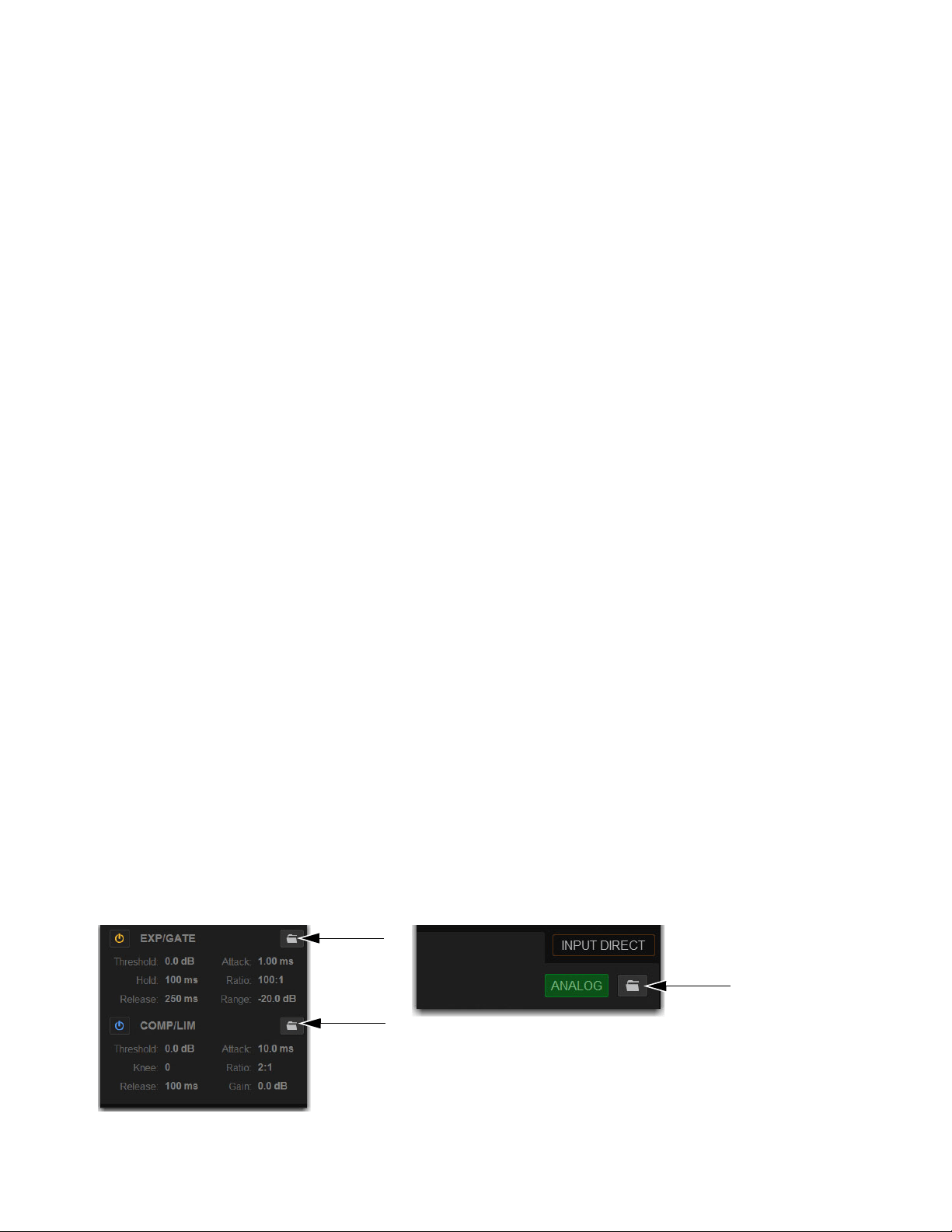
Overview, Inputs, and Outputs Pages 199
To preview and load a saved Channel Preset:
1 Navigate to the Inputs page for the desired channel. Channel Presets can only be loaded into a single channel at a time.
2 Select the Channel Presets icon to open the Presets window.
3 Choose a Presets folder from the Folder pop-up menu.
4 Do any of the following in the Presets window:
• To preview an existing preset, select its name in the Presets window so it is highlighted.
• To load the currently selected preset, select
OK.
• To load a preset and close the Presets window, double-tap the preset.
• To cancel without changing settings, choose
Cancel.
To rename, duplicate, overwrite or delete a Channel Preset:
Touch-and-hold (right-click) the preset name in the Preset window, then choose Rename, Duplicate, Delete, or Overwrite.
Channel Compatibility and Input Channel Presets
The following describe how different types of channel data is handled when storing or loading Input Channel Presets:
Channel Names and Presets
New presets automatically inherit the current Input Channel Name, or you can give them a custom
name in the Presets window. The default channel number (such as “Ch 16") is used for the preset name if the channel has an empty
(null) name.
Loading Mono to Stereo
Mono settings are applied equally to the left and right channels of the stereo destination. The stereo des-
tination channel retains its current balance and width settings.
Loading Stereo to Mono
When loading a stereo preset into a mono Input Channel, the left channel settings in the stereo preset are
applied to the mono destination channel. The mono destination channel retains its current pan setting.
Groups
Group bus assignments are not applied if the settings in the preset do not match the current system Bus Configuration
Aux Sends
Aux send level or pan settings for individual Aux sends are not applied if the stored mono/stereo state does not match
the current mono/stereo state. For example, assume the stored preset has Aux 1–2 combined as a stereo channel, but the current sys-
tem configuration has these Auxes as individual mono Auxes. When the preset is recalled Aux 1 and Aux 2 will retain their current
settings (they will not be updated), while all other Auxes are updated to the preset settings.
Presets for Built-In Channel EQs, Graphic EQs, and Dynamics
You can save and load built-in channel EQ, GEQ, and Dynamics settings as Preset files. Preset files are stored in Preset Folders,
and can be moved between systems and used with other Show files. Each processor has its own Presets folder in which settings are
stored and from which they are loaded. GEQ settings can only be accessed from the Outputs page.
To save or load presets:
1 Adjust parameters as needed.
2 Go to the Inputs or Outputs page and attention the channel whose settings you want to save or load.
3 Depending on the processor settings you want to save, select the corresponding Presets folder icon to open the Presets window.
Dynamics Presets Folder icons (left) and the channel EQ Presets Folder icon (right)
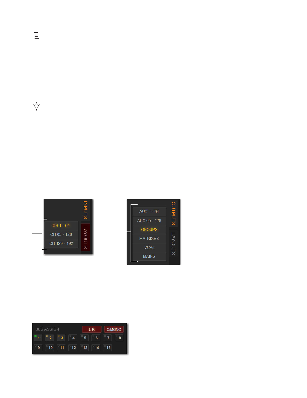
Overview, Inputs, and Outputs Pages 200
4 Choose a Presets folder from the Folder pop-up menu.
5 Do any of the following in the Presets window:
• To save the current settings as a new preset, choose New and enter a name for the preset file. All processor settings are saved
to the preset.
• To preview an existing preset, select its name in the Presets window so it is highlighted.
• To load the currently selected preset, select
OK.
• To load a preset and close the Presets window, double-tap the preset.
• To cancel without changing settings, choose
Cancel.
To rename, duplicate, overwrite or delete a Preset:
Touch-and-hold (right-click) the preset name in the Preset window, and then choose Rename, Duplicate, Delete, or Overwrite.
Assigning Channels to Buses and VCAs on the External Screen
You can assign channels to buses and VCAs on the external screen.
To assign channels to the Mains or Groups on the external screen:
1 Go to the Inputs or Outputs page, depending on the type of channels you want to assign.
2 Select the Inputs or Outputs tab.
3 Use the Input Channel Bank buttons or the Output Channel Type buttons to bank those channels to the fader strips.
4 Attention one or more channels.
5 In the Bus Assign section, do any of the following:
• To assign to Mains Left-Right, select the L-R button so it lights.
• To assign to the Center/Mono bus, select the C/Mono button so it lights.
• To assign to a Group, select Groups 1–x, as available, so they light. A group with a single yellow ring is mono, and interlock-
ing green rings is stereo.
You can create your own Presets folder from the Filing page, which then shows up in any Presets Folder pop-up menu. See
Cre-
ating Preset Folders
Check the Factory Presets folder for pre-configured settings, where available.
Input Channel Bank buttons (left) and Output Channel Type buttons (right)
Bus Assign section showing a channel assigned to Mains L-R, C/Mono, and Groups 1, 2, and 3

Overview, Inputs, and Outputs Pages 201
To assign channels to Aux buses on the external screen:
1 Go to the Inputs page.
2 Select the Inputs tab, then select the bank of input channels you want to access using the Input Channel Type buttons.
3 Attention an input channel.
4 In the Aux Sends section, select the thermometer-style indicator. When
the indicator lights, the send is on. The indicator lights in the color as-
signed to that Aux output.
5 To toggle an Aux Send pre-/post-fader, select the Aux Send number. When
set to pre-fader, a border appears around the Aux Send number.
Managing Output Channel Assignments (Members)
You can view, reset, clear and copy (duplicate) Mains, Aux, Group, Matrix, and VCA assignments (members) on the external
screen.
Viewing Output Assignments
When an output channel is targeted on-screen, its members are shown in the Members list on the right side of the Outputs page.
To view input assignments to an output:
1 Go to the Outputs page.
2 Select the Output Channel Type tab to show those channels on the screen.
3 Attention the desired output channel. Channels assigned to the attentioned output channel are displayed in the Members list on
the right side of the page.
To jump to any assigned input channel from the Outputs page:
Select the name of the input channel in the Members list.
Removing and Resetting Assignments
You can remove input assignments from an output on-screen.
To remove one input assignment from an output:
1 Attention the output channel you want to change so that its members are displayed on-screen.
2 In the Members list, touch-and-hold (right-click) the input assignment you want to remove and choose Unassign.
Channel assignments shown in the Members list
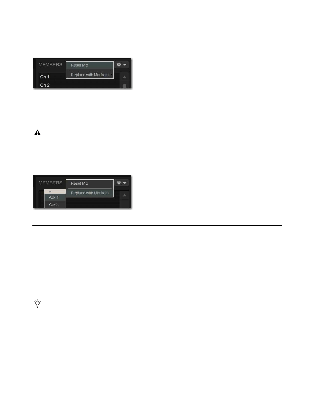
Overview, Inputs, and Outputs Pages 202
To remove all input assignments:
1 Attention the output channel you want to change so that its members are displayed on-screen.
2 Select the pop-up menu at the top of the Members list (gear icon), and choose Reset Mix (for buses) or Clear All Members (for
VCAs).
Copying Assignments Between Outputs
You can copy the current input assignments from one output to another of the same type. This lets you quickly duplicate monitor
mixes.
To copy input assignments between buses:
1 Attention the output channel to which you want to copy assignments.
2 Select the pop-up menu at the top of the Members list (gear icon), choose Replace With Mix From, and then from the list choose
the bus whose assignments you want to copy to the currently attentioned bus.
Color-Coding Channels from the External Screen
You can color-code channels to help identify key channels or groups of channels faster on the Inputs or Outputs page.
To set a channel color on the external screen:
1 Touch-and-hold (right-click) a fader strip on-screen, or select multiple channels and right-click any of the multi-selected faders.
2 From the pop-up, select Set Channel Color and choose one of the available color options.
The color coding is reflected in the MTS channel tiles; on the CTM for the color-coded channels; on the Channel Color switch; on
the CKM encoders for Aux Sends, Matrix input controls, Group assignment controls, and Mains assignment control; and on the
fader strips and the Aux Sends section on the external screen.
Removing all input assignments from a bus
Copying Aux bus assignments overwrites all the assignments on the destination Aux bus.
Copying input assignments between Aux buses
You can also color-code channels from the MTS. See
Color-Coding Channel from the Universe View.
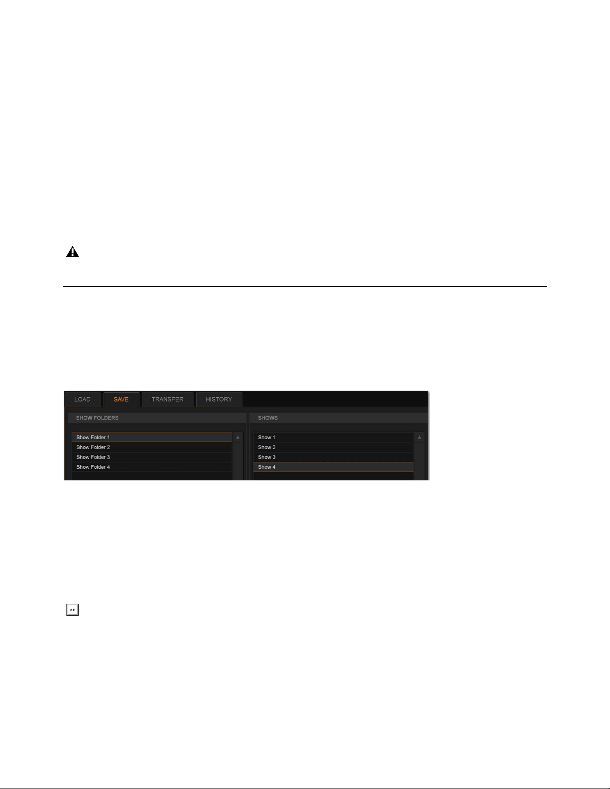
Filing 203
Filing
Data can be stored, recalled and transferred between VENUE systems, as well as VENUE Standalone software, using the Filing
page. There are three types of information files that can be managed separately, as follows:
Show Files
These files are used to store, recall and transfer system settings, snapshots, and events. (Snapshots and events can also
be imported from Show files.)
Preset Files
These files are used to store settings for input channels, built-in processors and plug-ins, User Layouts, Recall Safe
Scope Sets, and Events.
Console Setting Files
These files are used to transfer or back up the current state of the S6L system.
Creating Shows
A Show file contains all configuration, signal routing, mixer settings, plug-in information, snapshots, and other operational set-
tings. Shows are grouped together in Show Folders.
Show Folders
Show Folders contain Show files. You can create and manage Show Folders from the Save tab of the Filing page.
Creating Show Folders
To create a new Show Folder:
1 Go to the Filing page and select the Save tab.
2 In the Show Folders column, select the New button.
3 Type a name for the Show Folder and press Enter.
Duplicating Show Folders
To duplicate a Show Folders:
1 In the Show Folders column, select a Show folder so it is highlighted.
2 Select the Duplicate button.
The folder and all of the Show files it contains are duplicated.
The system does not need to be in Config mode to carry out many file management tasks. However, the system must be in Config
mode to load Shows. This minimizes the chance of an accidental interruption of audio throughput.
Show Folders and Show files in the Save tab of the Filing page
You can also touch-and hold (right-click)) any folders and file names in the Filing page columns and choose the relevant com-
mand from the pop-up.

Filing 204
Renaming Show Folders
To rename a Show Folder:
1 In the Show Folders column, select a Show folder so it is highlighted.
2 Select the Rename button.
3 Type a new name for the Show folder and press Enter.
Deleting Show Folders
When you delete a Show Folder, all Show files contained in that folder are also deleted.
To delete a Show Folder:
1 In the Show Folders column, select a Show folder so it is highlighted.
2 Select the Delete button.
Show Files
Creating a Show File
When you create a new Show file, it captures the current state of the system. Show files are automatically saved when they are cre-
ated.
To create a new Show file:
1 Go to Filing > Save.
2 In the Show Folders column, select the Show folder where you want to save the Show.
3 In the Shows column, select the New button. The new Show file captures the current state of the system.
4 Type a name for the Show file and press Enter.
5 Double-tap in the Notes field for the Show and type any comments you want to save with the Show.
Information about the Show file is shown in the Info area of the Filing page.
Overwriting (Updating) a Show File
You can also update an existing Show file by overwriting it.
To update (overwrite) an existing Show file:
In the Shows column, touch-and-hold (right-click) the Show file name you want to
overwrite, and choose
Overwrite from the pop-up menu. The current state of the system
is saved to the selected Show file.
– or –
Press the Over Write switch on the MLM.
Duplicating Show Files
To duplicate a Show file:
In the Shows column, touch-and-hold (right-click) the Show file name you want to overwrite, and choose Duplicate from the
pop-up menu.
Show files are automatically saved when they are created; no further action is required to save them.
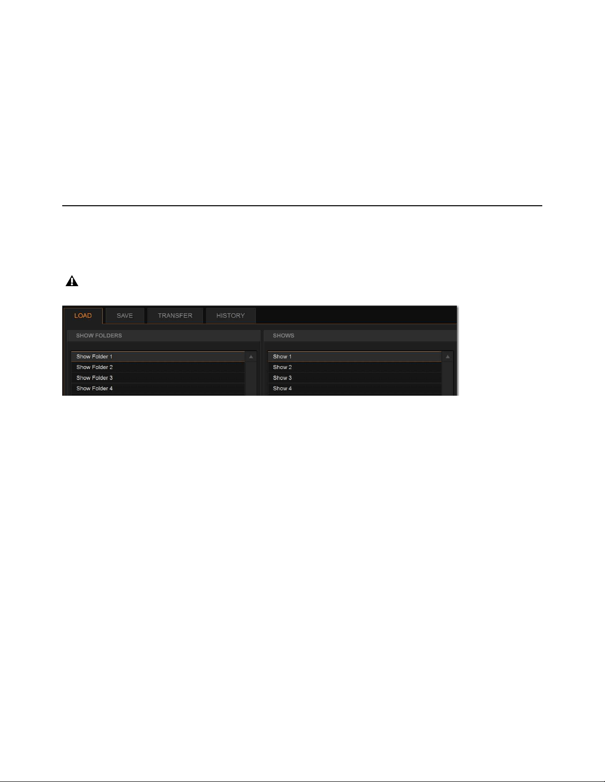
Filing 205
Renaming Show Files
To rename a Show file:
1 In the Shows column, select a Show file name so it is highlighted.
2 In the Shows column, select the Rename button, then type a new name for the Show file and press Enter.
Deleting Show Files
To delete a Show file:
1 In the Shows column, select a Show file name so it is highlighted.
2 In the Shows column, select the Delete button.
Loading a Show
You can load a Show file using the Load tab of the Filing page. Show files are stored locally on your system. Show files can be
stored on USB drives, but must first be transferred to the system before loading (see Transferring Settings, Shows and Presets).
The system must be in Config mode to load Shows.
To load a Show file:
1 Put the system into Config mode.
2 Go to the Filing page and select the Load tab.
3 In the Show Folders column, select a Show Folder name to select the folder. Any Show files in the folder are displayed in the
Shows column.
4 In the Shows column, select a Show file name so it is highlighted.
5 Select the Load button. The system loads the new Show file, replacing the current system configuration, routing, and control set-
tings with those contained in the new file.
System Configurations and Loading Shows
Show files include system configuration settings such as the type of control surface; the type of Engine and the number of HDX
Mix Engines; and Mains and Mix (Aux/Group) Bus configurations.
• If a Show file includes the same system configuration settings as the current configuration, the configuration information appears
in blue text in the Info area.
• If a Show file differs from the current configuration, but can be loaded on the system, the relevant configuration changes appear
in orange text in the Info area.
• If a Show file differs from the current configuration and cannot be loaded on the system in its entirety, the configuration infor-
mation appears in red text in the Info area.
• If a Show file includes active Event triggers that would not be activated when the Show is loaded due to the current state of the
control surface, a confirmation dialog appears letting you ignore those triggers or automatically activate them on Show load.
Loading a Show automatically replaces the current system settings, and may interrupt audio throughput.
Show Folders and Show files in the Load tab of the Filing page
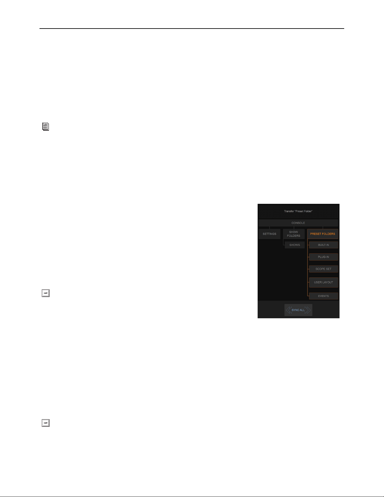
Filing 206
Working with Presets
Preset files are used to store, recall and transfer factory or user-defined presets. Preset files are grouped in the following types of
Preset Folders:
Built-in
Channel EQ, 31-band Graphic EQ, Compressor/Limiter, Expander/Gate, and Input Channel Presets.
Plug-In
Plug-ins Settings Files.
Scope Set
Settings for Recall Safe and User Aux Scope configurations.
User Layout
Custom User Layouts.
Events
Event definitions
Preset Folders
Preset Folders contain Preset files. Each of the built-in processors and each plug-in has its own Factory Defaults folder containing
pre-defined Presets. A User Presets folder, for storing your Presets, is also provided.
You can create additional Preset Folders and store new Presets in them. These folders can then be transferred to a portable storage
device for transfer to other VENUE systems.
Creating Preset Folders
To create a new Preset Folder:
1 Go to the Filing page and select the Transfer tab.
2 In the center column, select Preset Folders. A list of Preset Folders appears in the left
column.
3 In the left column, select the New button.
4 Type a name for the Preset Folder and press Enter.
The new Preset Folder is available in the Preset window for each processor or plug-in.
Duplicating Preset Folders
To duplicate a Preset Folder:
1 In the left column, select a Preset Folder so it is highlighted.
2 Select the Duplicate button.
The folder and all of the Preset files it contains are duplicated.
Renaming Preset Folders
To rename a Preset Folder:
1 In the left column, select a Preset Folder name so it is highlighted.
2 Select the Rename button.
3 Type a new name for the Preset Folder and press Enter.
For information on saving, previewing and loading presets, see any of the following:
Input Channel, EQ, and Dynamics Pre-
sets, Plug-In Presets and Snapshots, Using Scope Sets, Working with User Layout Presets, or Events Presets.
You can also touch-and hold (right-click) any folders and filenames in the Filing
page columns and choose the relevant command from the pop-up.
You can also touch-and-hold (right-click) a Preset Folder name and choose Rename, or double-click a Preset Folder name to
rename the folder.
Preset Folder
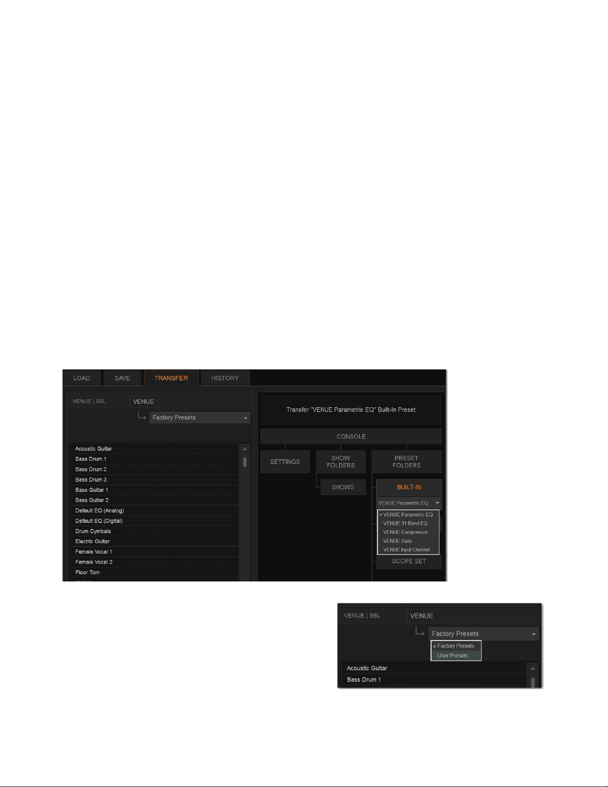
Filing 207
Deleting Preset Folders
When you delete a Preset Folder, all Presets contained in that folder are also deleted.
To delete a Preset Folder:
1 In the left column, select a Preset Folder name to select it.
2 Select the Delete button.
Preset Files
You can manage Preset files from the Transfer tab of the Filing page. You cannot create Preset files from the Filing page. Preset
files are created from the Presets window of the channel, processor, or plug-in. Scope Sets are created using the Scope Sets window
of the Snapshots page Recall Safe tab. User Layouts are created from the User tab of the
Inputs or Outputs page, and Events Presets
from the Events Presets window of the Control > Events page.
Duplicating Presets
To duplicate a Preset file:
1 Go to the Filing page and select the Transfer tab.
2 Select any of the following:
•Select Built-In or Plug-In then choose a processor or plug-in from the pop-up menu. The available Preset Folders for the pro-
cessor or plug-in appear in a pop-up menu above the left column.
•Select
Scope Set to select Recall Safe (Scope Sets) or User Aux Scope presets to transfer.
•Select User Layout to select User Layouts to transfer.
•Select Events to select Event definitions to transfer.
3 In the left column, choose a Preset Folder from the pop-up menu.
Any Presets in the folder appear in the left column.
4 In the left column, select a Preset file name so it is highlighted.
5 Select the Duplicate button.
Built-In EQ in the Transfer tab of the Filing page

Filing 208
Renaming Presets
To rename a Preset file:
1 In the left column, select a Preset file name so it is highlighted.
2 Select the Rename button.
3 Type a new name for the Preset file and press Enter.
Deleting Presets
To delete a Preset file:
1 In the left column, select a Preset file name so it is highlighted.
2 Select the Delete button.
Transferring Settings, Shows and Presets
You can copy Console Settings, Shows, and Presets to and from a portable storage device (such as a USB flash drive) for backup,
transfer from standalone software, and transfer between systems.
Settings, Shows and Presets cannot be loaded onto the destination system directly from the portable storage device, but must first
be transferred to the system before loading. Transfer of Settings files, Show files, and Preset files is managed from the Transfer tab
of the Filing page. The left column shows files on the system. The right column shows the contents of the portable storage device
in the right column. Items are selected for transfer in the center.
To transfer Settings, Shows or Presets between your system and a portable storage device:
1 Go to the Filing page and select the Transfer tab.
2 Connect a portable storage device such as a USB flash drive to the S6L control surface. The device appears above the right col-
umn.
3 Do one of the following to select the type of data to transfer:
• To transfer all data, select Console.
• To transfer Console Settings, select Settings.
• To transfer Show Folders, select Show Folders.
• To transfer individual Shows, select Shows.
• To transfer Preset Folders, select Preset Folders.
• To transfer Presets for individual items, select Built-In or Plug-In and choose a built-in processor or plug-in, or Input Channel
from the pop-up menu.
• To transfer Scope Sets for Recall Safe or User Aux Scope, select
Scope Sets and then choose the desired type (Recall Safe
or User Aux Scope) from the pop-up menu.
• To transfer User Layouts, select User Layouts.
• To transfer Events, select Events.
Console Settings are equivalent to an auto-saved Show file, and store the current state of the system. By transferring Console
Settings, you can transfer the current state of the system without having to first create and name a Show file.
Selecting Recall Safe or User Aux Scope
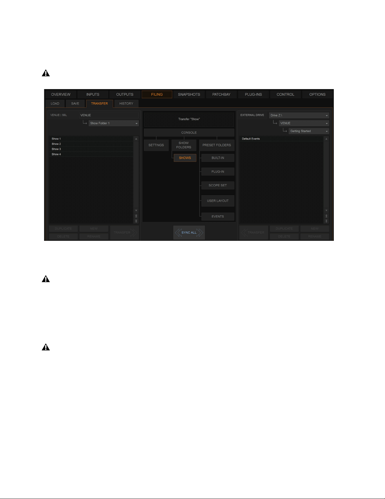
Filing 209
4 Do one of the following to select the items to transfer:
• In the left column, select the items you want to transfer to the portable storage device.
– or –
• In the right column, select the items you want to transfer from the portable storage device to your system.
5 Select the Transfer button.
Large transfers may take time. Transfer status is shown by a progress bar. A transfer may be canceled by selecting Cancel.
Synchronizing Settings, Shows and Presets
Instead of transferring data in one direction between the VENUE system and a portable storage device, you can synchronize all data
in both columns of the Transfer tab in a single operation.
Synchronizing data causes new files to be copied and files with the same name but a more recent modification date/time to be au-
tomatically updated on both devices.
To synchronize Settings, Shows, or Presets between the VENUE system and a portable storage device:
1 Go to Filing > Transfer.
2 Connect a portable storage device (such as a USB flash drive) to a USB port on the S6L control surface. The device appears
above the right column.
To transfer Console and Console Settings from an external device to your system, first enable Config mode.
Preparing to transfer a Show file to a USB storage device
Canceled transfers may result in partial folder contents, which will have to be deleted manually.
When synchronizing data, the VENUE software replaces data files of the same name with the file that has the most recent
date/time. Check to be sure that the system clock times and time zones are correctly set on the system and on the computer run-
ning the Standalone software when preparing data for synchronization.

Filing 210
3 Do one of the following to select the type of data to synchronize:
• To synchronize all data, select the Console icon.
• To synchronize Console Settings, select the Settings icon.
• To synchronize Show Folders, select the Show Folders icon.
• To synchronize individual Shows, select the Show icon.
• To synchronize Preset Folders, select the Preset Folders icon.
• To synchronize Presets for individual items, select the Built-In icon or the Plug-In icon and choose a processor or plug-in from
the pop-up menu.
• To synchronize Scope Sets for Recall Safe, select
Scope Sets
• To synchronize User Layouts, select User Layouts.
4 From the pop-up menus above each column, choose the folders containing the elements you want to synchronize.
5 Select the Sync All button. The contents of the left and right columns are synchronized.
Import Snapshots and Events
You can import Snapshots and Events from available Show files using the Import features on the Filing page. Importing snapshots
or events adds the imported items to the corresponding list (unlike Events Presets which replace all items in the Events list).
To import snapshots or events:
1 Make sure the Show file containing the desired items is present on your system. If not, use the Transfer page to do so.
2 Go to the Filing page and select the Load or Save tab.
3 Select the Show folder that contains the Show file from which you want to import.
4 In the Shows column, select the Show file from which you want to import.
5 Touch the Import button and choose Import Snapshots or Import Events from the pop-up menu.
The right-click snapshots command Import that was available in previous versions of VENUE software for S6L is no longer in the
right-click menu. Use the Import button in the Filing page instead.
Import pop-up in Filing > Load
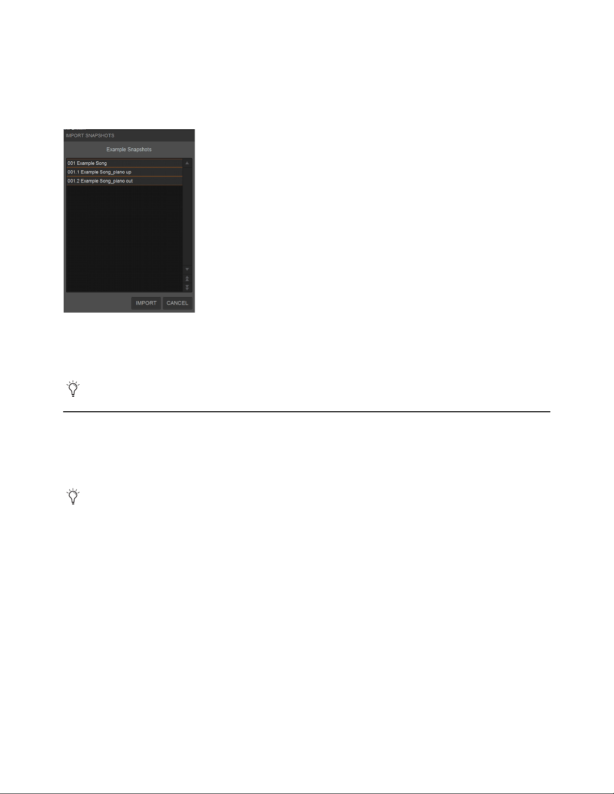
Filing 211
6 In the Import Snapshots or Import Events window, select one or more items so they are highlighted in the list.
When selecting snapshots:
• Selecting a Parent snapshot selects all its affiliated Child snapshots.
• Selecting a Child snapshot but not its Parent will result in the Child snapshot being redesignated as a Parent after it is imported.
• To deselect a selected snapshot, hold Ctrl and tap the snapshot you want to remove from the selection.
7 Tap the Import button.
The selected items are added to the Snapshots or Events list of the currently loaded Show and have an asterisk (*) added to the
end of their snapshot or event name.
Undoing Changes Using the History Feature
The VENUE system automatically saves the current state of the system while you are working, allowing you to quickly return the
system to a previous state.
The History feature uses Show files to capture the system state, and displays the files in the History tab.
Show Folders in the History tab
There are two Show Folders in the History tab:
The Most Recent Changes folder includes all auto-saved Show files for a ten-hour period.
The Previous Days folder includes only the last auto-saved Show file for each day since the system was last cleared.
Show Files in the History tab
The auto-saved Show files displayed in the History tab are named according to the date and time of their creation, and cannot be
renamed.
The Notes field for each auto-saved Show file includes a description of the conditions that caused the automatic save.
Several conditions cause the system to automatically save a new Show file in the History tab, as follows:
In the course of normal work, a new Show file is automatically saved in the History tab approximately every ten minutes. Saves
are less frequent when the system is idle.
A new Show file is automatically saved just prior to a significant change in the system setup, including:
Import Snapshots
Any single Show file can contain a maximum of 999 snapshots and up to 999 events.
Show Folders and Show files displayed in the History tab can only be loaded or deleted. They cannot be duplicated or renamed.
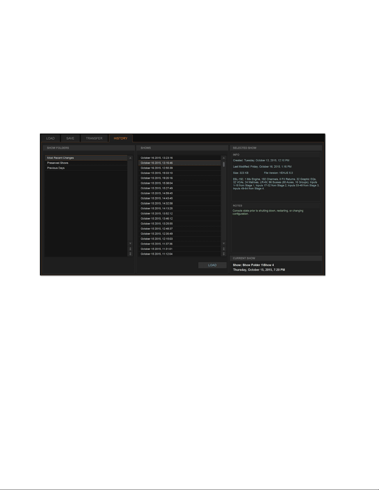
Filing 212
• Change of system channel or bus configuration
• Recall, storage, or modification of a Snapshot
• Loading of Console Settings or a Show
Loading an Auto-Saved Show
To return the system to an earlier state at any time, you can load any of the auto-saved Show files displayed in the History tab.
To load an auto-saved Show file:
1 Go to the Filing page and select the History tab.
2 In the Show Folders column, select the Show Folder name to select the folder and display its contents in the Shows column.
3 In the Shows column, select the name for the Show you want load.
4 Select the Load button.
The VENUE system loads the selected Show file, replacing the current system configuration, routing, and control settings with
those contained in the selected file.
The History tab of the Filing page

Snapshots 213
Snapshots
Snapshots let you flexibly store and recall a wide range of mixing parameters. Snapshots are commonly used to store the mixer
setup and levels for individual scenes, songs or sound cues in a performance. Snapshots store information about channels and mix
parameters, and you can use a variety of methods to edit, preview, filter, and manage snapshot data.
Snapshots are contained and stored as part of a Show file. A single Show file can contain up to 999 snapshots. Once stored, snap-
shots can be recalled manually or automatically (triggered by events or incoming time code). Snapshots are controlled from the
on-screen Snapshots page.
This section covers the following topics:
•
Snapshots Page Overview
• Creating Snapshots
• Hierarchical Snapshots (Parent and Child Snapshots)
• Momentary Snapshots
• Snapshot Groups
• Recalling Snapshots
• Managing Snapshots
• Making Changes to Snapshots
•Using Preview Mode
• Adding MIDI and Plug-In Data to Snapshots
• User Aux Scope
•Using Recall Safe
• Automation Safing Channels
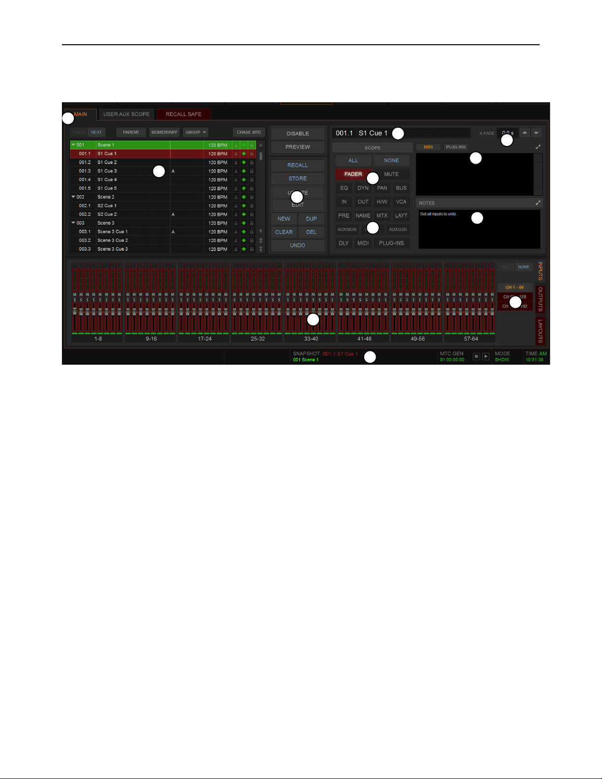
Snapshots 214
Snapshots Page Overview
The Snapshots page provides controls for storing, recalling, and managing snapshots, providing a central location for setting up and
replaying automated performances.
Main, User Aux Scope, and Recall Safe Tabs
The Snapshots page provides Main, User Aux Scope, and Recall Safe tabs.
Main
Provides the primary snapshot controls.
User Aux
Provides a matrix of Auxes that can be scoped individually per input channel. See User Aux Scope.
Recall Safe
Provides a matrix of channel parameters that can be globally safed (or isolated) from Recall for all snapshots. See Re-
call Safe.
1 – Main, User Aux Scope, and Recall Safe Tabs
2 – Snapshots List
3 – Snapshot Command Buttons
4 – Snapshot Scope Controls
5 – Channel Scope Controls
6 – Currently Targeted Snapshot Display
7 –
Snapshot Crossfade Controls
8 – MIDI/Plug-Ins List
9 – Snapshot Notes
10 – Snapshot Status Display
2
4
4
5
5
6
7
8
9
3
1
10

Snapshots 215
Snapshots List
Snapshots can be targeted, renamed, recalled, previewed, edited, locked, reordered, duplicated, searched, and deleted from the
Snapshots list. You can also designate snapshot hierarchy (Parent/Child snapshots), create Momentary snapshots, and create snap-
shot Groups. Icons are provided showing the status of various snapshot attributes.
Snapshot Entries
By default, each item in the Snapshots list has a number (001–999) and name. Numbering will be different for Parent/Child snap-
shots, and Momentary snapshots, as follows:
• Child snapshots are automatically numbered corresponding to their Parent snapshot, with a decimal number (such as .1, and
.2). For example, for a Parent snapshot 001, its first associated Child snapshot is numbered 001.1.
• Momentary snapshots do not have a number.
Snapshot Entry Status Indication
Snapshot entries in the Snapshots list are highlighted in the following colors to indicate their statuses:
Green
Indicates the currently recalled snapshot.
Red
Indicates the currently targeted snapshot.
Yellow
Indicates that the snapshot is both the currently recalled and the currently targeted snapshot.
Blue
Indicates that the snapshot is part of a multi-selection but not the last recalled or currently targeted snapshot.
Snapshot Attribute Icons
To the right of each snapshot number and name are icons indicating the status of the available snapshot attributes. Icons can be
shown or hidden The following attributes have icons:
• Each snapshot provides a MIDI icon that lights if MIDI messages are included in the snapshot (See Adding MIDI Data to
Snapshots.)
• If either the MIDI Read or Generate feature is enabled, each snapshot shows a time code value, trigger indicator, or send in-
dicator. (See Snapshot Time Code Display.)
• If system Tempo has been enabled in Options > Misc, Tempo data can be shown for each snapshot instead of MIDI. Each
snapshot shows an associated tempo, along with a Tempo On/Off toggle icon. (See Adding Tempo Data to Snapshots.)
• On systems connected to a compatible Pro Tools system with VENUE Link enabled, a snapshot can be configured to create
a Marker in the Pro Tools recording when that snapshot is recalled. The diamond-shaped Markers icon toggles this feature
on/off for each snapshot. (For more information, see the S6L Live Recording Guide.pdf.)
• Each snapshot provides a Lock icon that toggles the snapshot between Locked (write-protected) and Unlocked. See Locking
Snapshots.
To show or hide snapshot attribute icons:
Touch-and-hold any snapshot in the Snapshot list and select Show or Hide any of available attributes.
When snapshots are assigned to a Snapshot Group, the letter of the assigned Groups is also shown in the list. Group assignment is
always displayed and cannot be hidden.
Recall Buttons (Prev and Next)
The Recall Previous (–) and Recall Next (+) buttons at the top of the Snapshots list cause the previous or next snapshot in the list
to be targeted and recalled in one step.
Parent / Child
Designates one or more items as Parent or Child snapshots. See Hierarchical Snapshots (Parent and Child Snapshots).
Both MIDI and Tempo are available parameters at all times. However, the Snapshots list can only display one or the other at
a time.
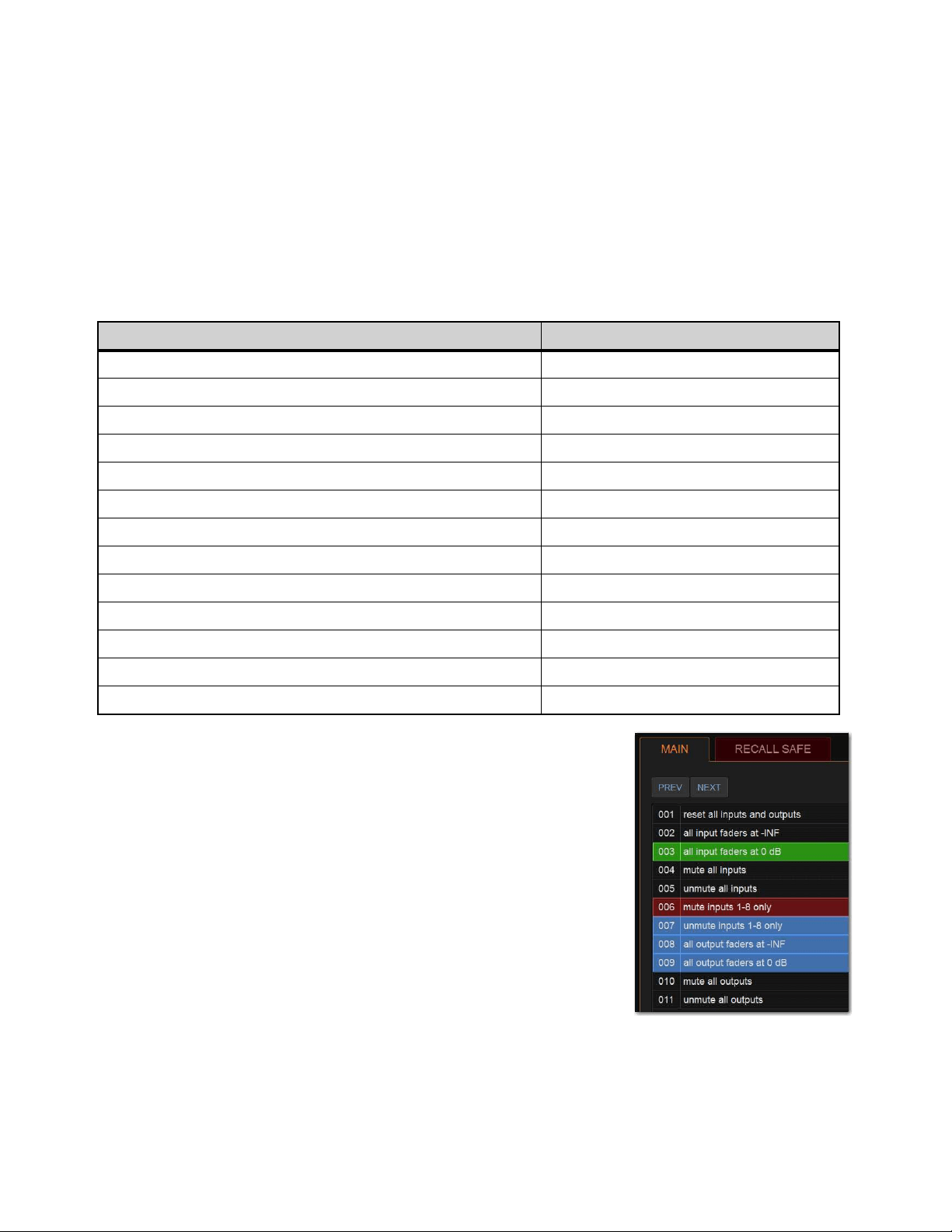
Snapshots 216
Momentary / Sequential
Designates one or more items as Momentary snapshots. See Momentary Snapshots.
Group
Assigns or unassigns one or more selected snapshots to Snapshot Groups. See Snapshot Groups.
Chase MTC/LTC
Enables or suspends automated recall of snapshots when either the MTC/LTC Read or MTC Generate option is enabled.
Snapshot Keyboard Shortcuts
When the Snapshots page is displayed, you can perform the following snapshot functions with these keyboard shortcuts:
Selecting Snapshots
You can select single snapshots or multiple snapshots in order to target, recall, dupli-
cate, edit, lock, designate, group, or delete them in the snapshots list.
To select multiple consecutive snapshots:
Hold the Shift key and select the snapshot names in the Snapshots list.
To clear a selection of multiple consecutive snapshots:
Select any snapshot name in the Snapshots list.
– or –
Rotate the encoder in the Snapshots section of the MLM.
To select or de-select non-consecutive snapshots:
Hold the Ctrl key and select the snapshot names in the Snapshots list.
Snapshot Function Keyboard Shortcut
Target Next/Previous Snapshot Up/Down Arrow keys
Target First Snapshot in List Home key
Target Last Snapshot in List End key
Target Snapshot at Top of Page Page Up
Target Snapshot at Bottom of Page Page Down
Select Multiple Consecutive Snapshots Shift-select snapshots
Select Multiple Non-Consecutive Snapshots/Deselect any Snapshot Ctrl-select snapshots
Select All Snapshots Ctrl + A
Create New Snapshot Ctrl + N
Recall Targeted Snapshot Ctrl + R
Store Targeted Snapshot Ctrl + S
Undo Ctrl + U
Add or update MIDI/Plug-in data to snapshot Touch-and-hold MIDI/Plug-ins entry
Multiple items selected in the
Snapshots list
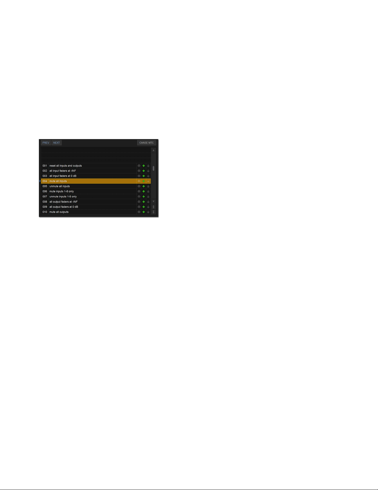
Snapshots 217
Snapshot Type Text Search
Type Text search lets you use the keyboard for fast navigation of the Snapshots list.
To search for and target a snapshot:
1 Go to the Snapshots page.
2 Type the number of the snapshot, or type the first letters of the snapshot name.
3 Press the Tab key on your keyboard to cycle through any snapshots that start with the same letter.
Centering the Snapshot List
The Options > Snapshots page provides a preference setting to always center the Snapshot list on the last recalled snapshot. This
setting lets you always view the snapshots immediately above and below (prior to and following) the last recalled snapshot. This
setting only affects the scroll position of items in the Snapshot list.
To center the Snapshot list on the last recalled snapshot:
In the Snapshots General Preferences section of the Options > Snapshots page, select Center Last Recalled Snapshot.
In the Snapshot list, a blue pointer appears to the left of the center position.If a Momentary snapshot recalled, it is centered in
the list, but pressing Previous or Next recalls the snapshot above or below the previously recalled snapshot, respectively, not the
previous or next Momentary snapshot (if any). For more information, see
Momentary Snapshots.
Snapshot Command Buttons
Disable
Temporarily disables all snapshot functions.
Preview
An “offline” mode in which the system continues to process audio using its settings at the time Preview is invoked, letting
you recall, edit and manage snapshots without affecting the current mix.
Recall
Recalls the targeted snapshot, updating the system to reflect the status of all scoped data types and channels in the snapshot
(subject to the current Recall Safe settings). If the setting Confirm Snapshot Recall is enabled in the Options > Snapshots page, a
confirmation dialog appears requiring you to confirm that you want to recall the snapshot.
Store
Stores the current state of the system in the targeted snapshot for all data types and channels, overwriting any existing data
in the snapshot.
Update
Lets you apply isolated changes to one or more snapshots at once (such as updating a channel EQ across all snapshots).
Edit
Enables Edit mode. Lets you adjust parameters freely and apply those changes to one or more snapshots. Changes can be ap-
plied in Absolute or Relative fashion.
Undo
Returns the system to its state before the last snapshot command.
New
Creates a new snapshot that captures the current state of all data types and channels.
Duplicate
Creates a copy of the selected snapshots.
Clear
Clears the contents of the targeted snapshot, but retains any associated MTC information.
Delete
Deletes the targeted snapshots.
Snapshot list with Center Last Recalled Snapshot enabled
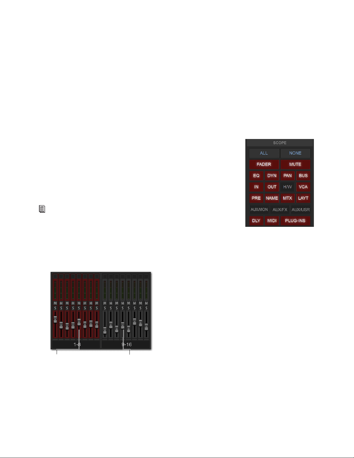
Snapshots 218
Snapshot Scope Controls
When you create a snapshot, it captures the current state of all system settings. However, you can select which of these settings you
want to be recalled when you recall a particular snapshot.
The selection of data types and channels that are recalled when you recall a snapshot is referred to as the scope of a snapshot. The
Snapshot Data Type buttons and on-screen faders determine (and display) the data types are recalled for which channels.
The Recall Safe tab provides global control of automation safe status for parameters on individual channels. The User Aux Scope
tab lets you specify scope for individual Auxes on a per-Input channel basis.
Scope States
Scoped
Red display indicates that the data type or channel is currently scoped and will be affected by snapshot recall.
Not Scoped
Gray display indicates that the data type or channel is not currently scoped and will not be affected by snapshot recall.
Data Type Scope Buttons
The Snapshot Data Type Scope buttons display scope status for the corresponding types of
controls on the control surface. See Table 5 on page 261 for a complete list.
Data Type Scope Action Buttons
All
Turns on the scope for all data types at once. This is equivalent to selecting all of the Data
Type buttons so they are lit red.
None
Turns off the scope for all data types at once. This is equivalent to deselecting all of the
Data Type buttons so they are unlit.
Channel Scope Controls
Channels are included or excluded from snapshots by selecting them on-screen in the Snapshot Channel Faders display. The Snap-
shot faders display the scope status of each channel, along with indication of the fader positions and mute states that will result by
recalling the targeted snapshot.
By default, you cannot adjust fader position, Solo, Mute, and Safe status directly from the Channel Scope controls. You can choose
to enable this ability by enabling the
Enable Strip Control on Snapshots Tab setting.
For a list of parameters associated with each Data Type, see Snapshot Data Types
and Parameters.
Snapshot channel fader display showing different scope states
Channels
currently scoped
Channels not
currently scoped
(lit, red)
(unlit, gray)
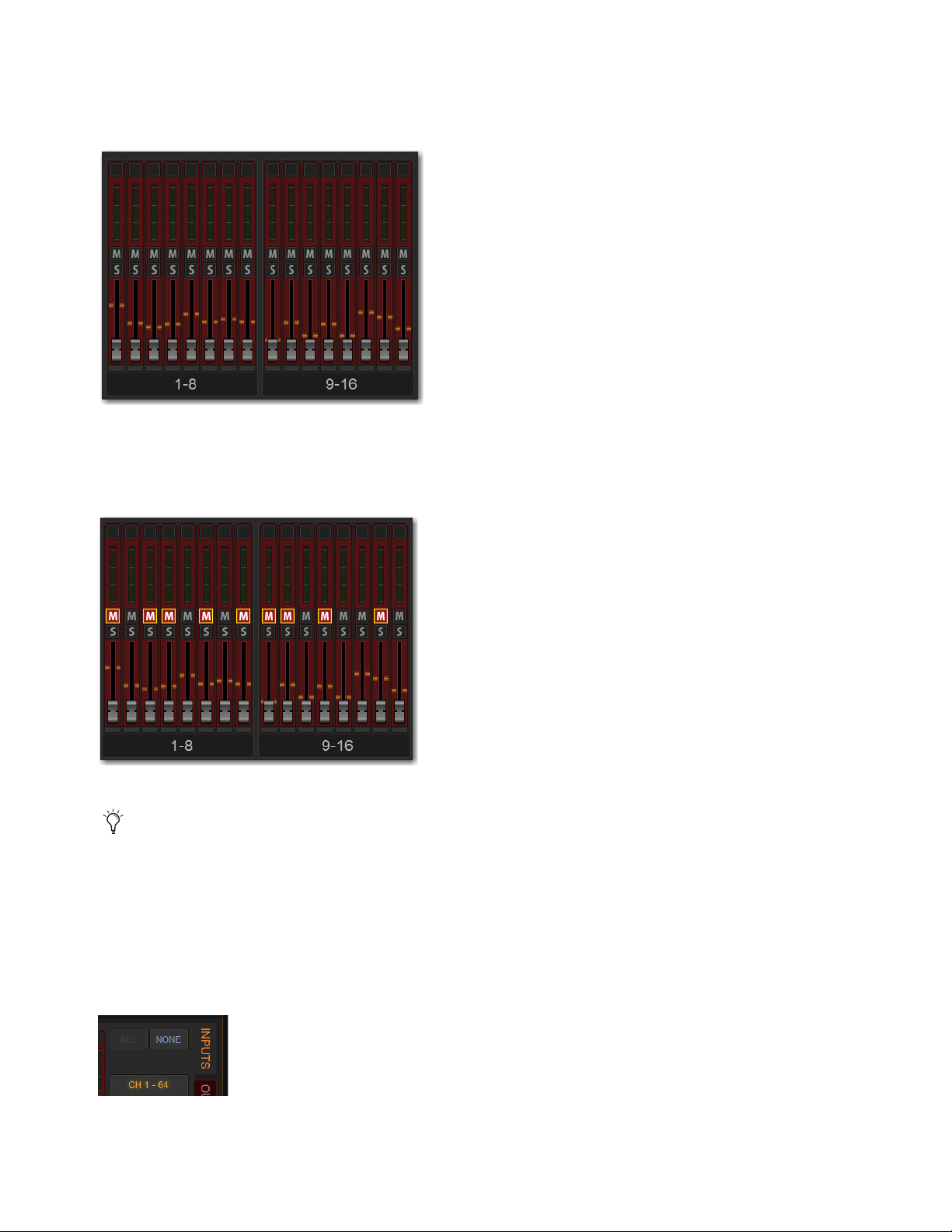
Snapshots 219
Channel Fader Position
When you target a snapshot with scoped channels that have different fader positions from the current fader positions, the target
fader positions are shown in bright red.
Channel Mute State
When you target a snapshot with scoped channels that have different mute states from the current mute states, the target mute but-
tons are outlined in yellow.
Channel Scope Action Buttons
All
Turns on the scope for all channels displayed on the current tab (such as 1–64). Double-tapping the All button turns on the scope
for all channels on the system.
None
Selecting the None button turns off the scope for all channels on the current page. Double-tapping the None button turns off
the scope for all channels on the system.
Snapshot channel fader display showing target fader positions
Snapshot channel fader display showing target mute states
Though the currently selected channel is displayed in the Snapshots page, keep in mind that you cannot target a different chan-
nel from this page. The currently selected (target) channel is indicated for visual reference only. To select and target a different
channel, use the channel Select switches or the Channel Scroll buttons.
Channel Scope Action Buttons
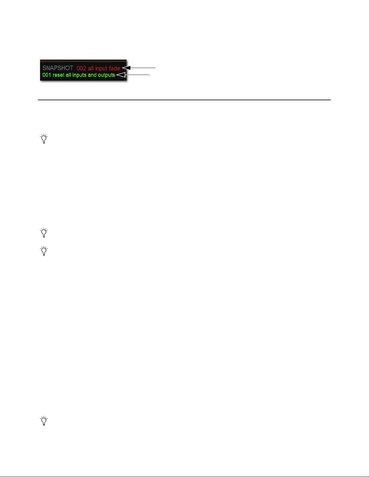
Snapshots 220
Snapshot Status Display
The Snapshot Status display shows the numbers and abbreviated names of the currently targeted snapshot (in red text) above the
currently recalled snapshot (in green or yellow). Recalling the targeted snapshot makes it the currently recalled snapshot.
Creating Snapshots
Snapshots can be created at any time to store the current channel and parameter settings. You can create new snapshots manually
in the Snapshots page, or by duplicating existing snapshots to build your mix as you work.
Creating New Snapshots
When you create a snapshot, it captures the current state of all system settings. When recalling a snapshot, you can selectively recall
parameters using the snapshot scope controls.
To create a new snapshot:
1 Set parameters as you want them to be stored in the snapshot.
2 Select New. The new snapshot appears in the Snapshots list.
Naming Snapshots
New snapshots are automatically numbered and appear as “<Untitled>” in the Snapshots list. Snapshots can be renamed at any
time. You can undo snapshot naming operations.
To name a snapshot:
1 Do one of the following:
• Double-tap the snapshot name in the Snapshots list or the current target name display.
• Touch-and-hold the snapshot name and choose
Rename.
2 Type a name for the snapshot.
3 Press Enter on the keyboard or select another snapshot name.
Adding Notes to Snapshots
You can add notes to snapshots at any time. You do not need to store the snapshot to save the notes in the snapshot.
To add or edit comments for a snapshot:
1 Double-select the Notes header or select the Expand icon to expand the Notes field.
2 Double-select in the Notes field and enter text.
Next Snapshot (top) and Last Recalled snapshot (bottom) in the Status area
Use the first snapshot in a Show file to establish the basic settings for a performance. For subsequent snapshots, use the scope
controls, User Aux Scope, and Recall Safe settings to selectively recall only those controls that need to change between sections
or songs, leaving other controls unaffected by snapshot recall.
You can undo the New snapshot command at any time by pressing the Undo Snapshot Command button.
When you create a new snapshot it automatically inherits the channel and data type scope of the currently targeted snapshot.
MIDI and plug-in data is not captured when a snapshot is created. This data is added to existing snapshots directly from the
MIDI/Plug-Ins lists. See
Adding MIDI and Plug-In Data to Snapshots.

Snapshots 221
Hierarchical Snapshots (Parent and Child Snapshots)
The Snapshots List lets you organize snapshots into a two-level hierarchy consisting
of Parent (primary) and Child (secondary) snapshots. The ability to designate Parent
and Child snapshots makes it easier to manage multiple snapshots associated with a
scene, song, or other segment of a performance.
Up to 99 Child snapshots can be associated with a single Parent snapshot. Child snap-
shots are automatically numbered corresponding to their Parent snapshot, with a dec-
imal number (such as .
1, and .2). For example, for a Parent snapshot 001, its first as-
sociated Child snapshot is numbered 001.1. Parent snapshot numbers are unaffected
by adding or removing Child snapshots.
You can optimize how hierarchical snapshots are displayed in the list by
Collapsing and Expanding Parent/Child Views. The
Snapshot List also provides tools for Managing and Editing Hierarchical Snapshots.
Designating Snapshots as Parent or Child
You can designate snapshots as Parent or Child snapshots in the following ways:
• By selecting one or more snapshots and using the Parent/Child button on-screen in the Snapshots tab
• Using drag and drop in the Snapshots list
• By editing the Snapshot Number
To designate snapshots as Parent or Child snapshots in the Snapshot List:
1 Click to select one or more snapshots in the list.
Above the Snapshot List, the Parent/Child button displays Child or Parent depending on what is selected in the Snapshots List:
• When one or more unaffiliated or Parent snapshots are selected, the button becomes Child.
• When one or more Child snapshots are selected, the button becomes Parent.
• When both Parent and Child snapshots are selected, or if no snapshots are selected, the button is unavailable.
2 Click the Parent/Child button on-screen, as appropriate for the selected snapshot.
The selected snapshots are designated as Parent or Child. Parent snapshots show an Expand/Collapse icon next to their number.
Multiple unaffiliated snapshots 002–006 selected in the Snapshot List
Child snapshots 001.1–001.5 associated with a Parent snapshot 001
Parent
Child
Parent
Child
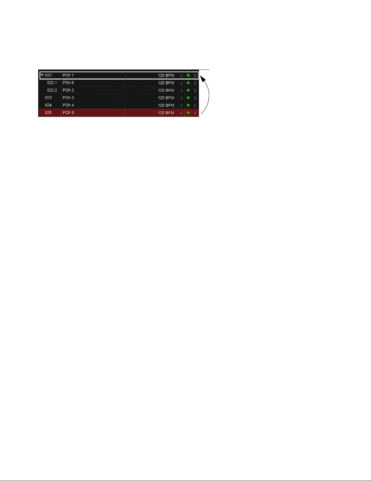
Snapshots 222
To designate a snapshot as a Child snapshot using drag and drop:
1 Make sure there is at least one Parent snapshot in the list, with at least one Child snapshot associated with it.
2 In the Snapshot list, drag the desired snapshot onto a Parent snapshot (indicated by the destination Parent becoming outlined in
white), then drop the new snapshot.
The snapshot is moved, designated as a Child snapshot, and renumbered. While using drag and drop, the following rules apply:
• Dropping a Parent snapshot onto an existing Parent designates it as a Child snapshot. If the moved Parent has any associated
Child snapshots, the moved Parent and all its associated Child snapshots are moved and renumbered.
• You cannot drop a Child snapshot onto an existing Child snapshot.
• When a Child snapshot is dragged and dropped outside of its Parent, it becomes a standard (unaffiliated) snapshot.
Snapshots can also be designated as Parent or Child by editing their Snapshot number.
To designate Parent or Child snapshots by editing Snapshot number:
1 Double-click the displayed Snapshot number (such as 001).
2 To designate a Child snapshot, enter a number-decimal-number (such as 15.1) and press Enter.
• If the first numbers correspond to an existing Parent snapshot, the edited snapshot becomes a Child associated with that Par-
ent. For example, if there is a Parent snapshot numbered 015 and you edit a different snapshot number to 15.1, that edited
snapshot becomes a Child (015.1) to the Parent 015.
• If that same Parent snapshot (015) has two Child snapshots 015.1 and 015.2, editing an unaffiliated snapshot number (such as
018) to become 15.2 places the edited snapshot as the second Child, and renumbers the previously numbered 015.2 snapshot
to 015.3. Any other higher numbered Child snapshots are similarly incremented.
• If the edited snapshot number is higher than any existing Parent snapshot, the edited snapshot becomes a Child of the highest
numbered Parent in the list. For example, if there are five Parent snapshots 001–005, editing the Snapshot number of one snap-
shot to become 8.1 results in the edited snapshot becoming snapshot 005.1 (a Child of the highest numbered Parent, 005).
Designating a Child snapshot by dragging and dropping a snapshot (025) onto a Parent (022)
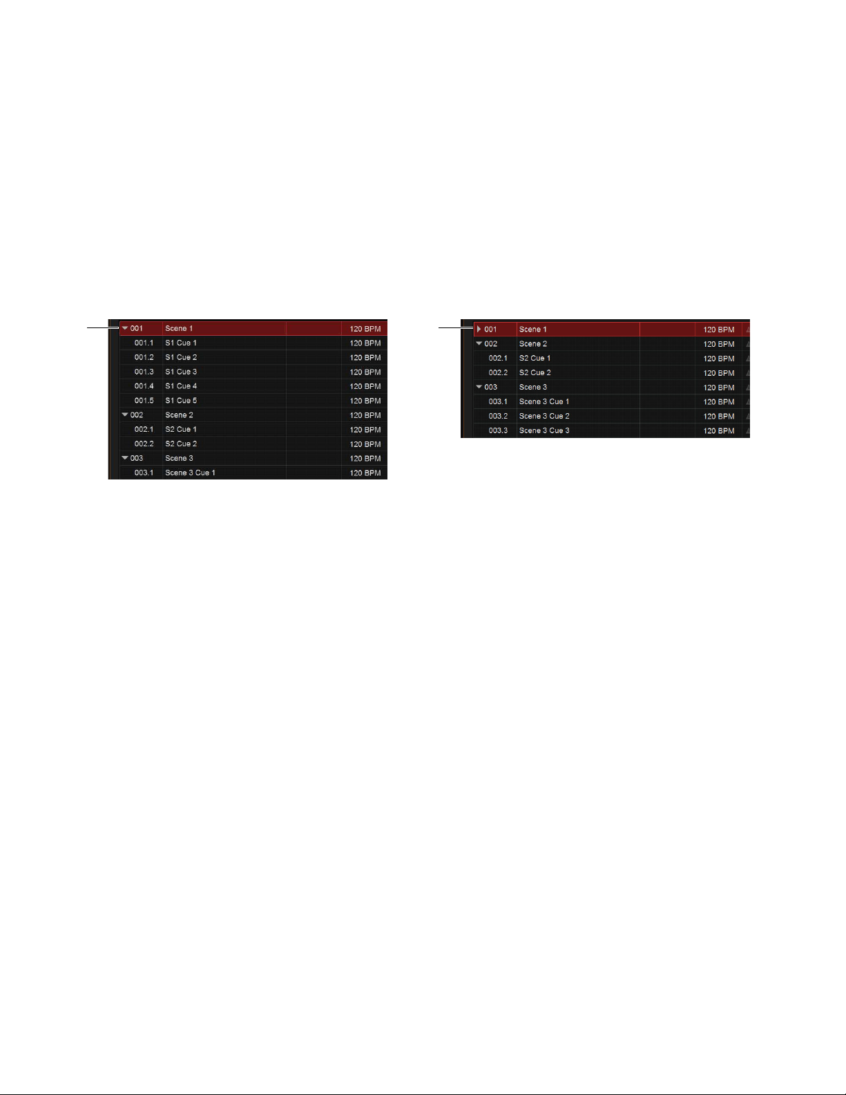
Snapshots 223
Collapsing and Expanding Parent/Child Views
Parent/Child snapshot views can be expanded or collapsed in the Snapshot List. When expanded, all Child snapshots associated
with a Parent are displayed in the list. When collapsed, only the Parent snapshot is displayed.
Collapsing Snapshot families make the Snapshots List easier to manage when selecting and rearranging snapshots, such as when
reordering a song, song list, or scenes for a performance.
Views can be expanded and collapsed manually, and will auto-expand/collapse when moving, designating, and recalling snapshots.
Manually Collapsing and Expanding Parent/Child Views
To collapse or expand a Parent and its associated Child snapshots:
1 Select a Parent in the Snapshot List.
2 Tap to toggle the Expand/Collapse icon to the left of the Snapshot number.
Automatic Collapse and Expand
Parent/Child views automatically expand or collapse when the following occur:
• Collapsed snapshot views automatically expand when a collapsed Child snapshot is recalled, and whenever a Child snapshot
is added to or removed from that family of snapshots.
• Recalling a Child snapshot associated with a different Parent automatically collapses the auto-expanded snapshot view (the
Parent of the newly recalled Child is automatically expanded).
• Collapsed Parent snapshots are highlighted whenever any associated Child snapshot is selected.
• When a Child snapshot in an expanded view is selected, collapsing that view deselects the Child. If the previously selected
Child was also the Target snapshot when the view was collapsed, its Parent becomes Targeted and selected.
Managing and Editing Hierarchical Snapshots
You can rearrange, update, edit, delete, and duplicate hierarchical snapshots similar to standard snapshots but with additional ca-
pabilities and choices to simplify list management tasks.
Rearranging Parent and Child Snapshots
Rearranging Parent snapshots in the list automatically updates their snapshot numbers just like standard snapshots. All associated
Child snapshots move with the Parent, and Child snapshot numbers are also updated. For example, moving a Parent snapshot 001
so it becomes the second Parent renumbers that Parent to 002, and its Child snapshots are renumbered 002.1, 002.2 and so on.
Child snapshots can be rearranged by dragging them up or down among other Child snapshots associated with the same Parent, and
their numbering is automatically updated. Child snapshots can be renamed just like standard snapshots.
When rearranging Parent or Child snapshots, views automatically expand or collapse (see
Automatic Collapse and Expand).
Editing Parent and Child Snapshots
When updating, storing, deleting, or duplicating a Parent snapshot you can choose whether to update the selected snapshot only
(
Selected Only), or to apply the change to all associated (Child) snapshots (All).
Expand/Collapse icon shown when expanded (at left) and collapsed (at right)
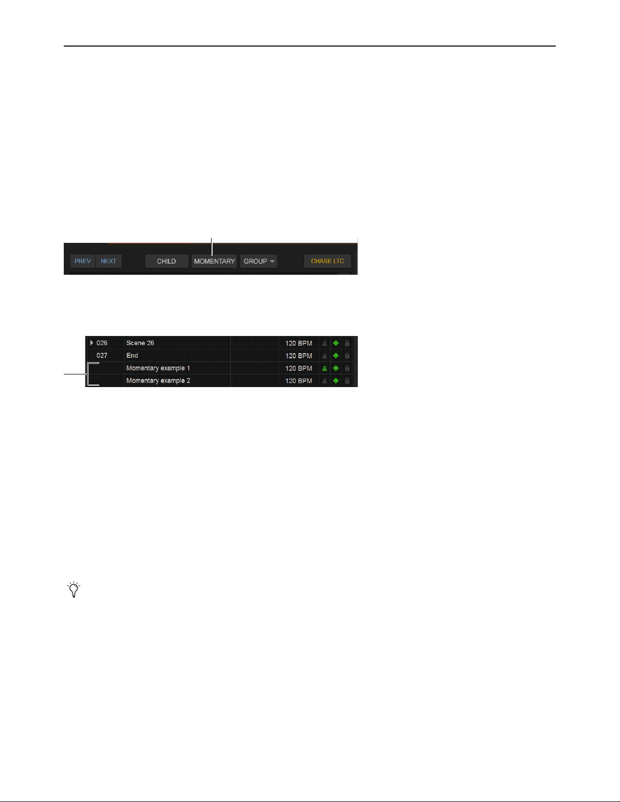
Snapshots 224
Momentary Snapshots
You can designate one or more snapshots as Momentary snapshots. Momentary snapshots are non-sequential, and have no associ-
ated snapshot number. Recalling Momentary snapshots does not change the Currently Recalled or Targeted state of the list.
Use Momentary snapshots for any situation in which you need to recall one or more parameters without losing your current place
in the Snapshot List. For example, if a vocal mic goes out during a performance you can recall a Momentary snapshot that only
changes the patching for the vocal channel to the input of a spare/backup mic. The Snapshot List remains unchanged.
Creating Momentary Snapshots
To create a Momentary snapshot:
1 Create a new snapshot, or select an existing Parent snapshot in the list (Child snapshots cannot become Momentary snapshots).
2 Tap the Momentary button above the Snapshot List.
The snapshot is moved to the end of the Snapshot list, and is not numbered. To convert the Momentary snapshot back to a stan-
dard snapshot, select the Momentary snapshot (the Momentary button becomes Sequential) and tap the Sequential button.
Recalling Momentary Snapshots
Momentary snapshots can be recalled manually by selecting them in the Snapshot List.
To recall a Momentary snapshot manually in the Snapshot list:
Select and recall the snapshot just as you would for a standard snapshot:
• Scroll the list or use Type Text Search to select the desired snapshot.
• Press
Recall.
• Define an Event that recalls the snapshot.
In the Snapshot List the recalled Momentary snapshot lights red, and the previously recalled snapshot lights green. If the Center
Last Recalled Snapshot option is enabled in Options > Snapshots, the Momentary snapshot is centered in the list. Pressing Pre-
vious or Next recalls the snapshot above or below the previously recalled snapshot in the list, respectively.
Editing Momentary Snapshots
Momentary Snapshots can be selected, renamed, Stored, Updated, and Edited just like standard snapshots. In addition:
• Momentary snapshots can be reordered in the list by dragging and dropping them between other Momentary snapshots.
• Moving a Momentary snapshot and dropping it between standard snapshots converts it into a standard (sequential) snapshot
with an appropriate snapshot number.
• Moving a Momentary snapshot onto an existing Parent or between Child snapshots converts it into a Child snapshot with an
appropriate snapshot number.
Momentary Snapshots do not support Parent or Child designation, but can be assigned to
Snapshot Groups.
Momentary button
Momentary snapshots in the list
Momentary snapshots can also be recalled via time code.
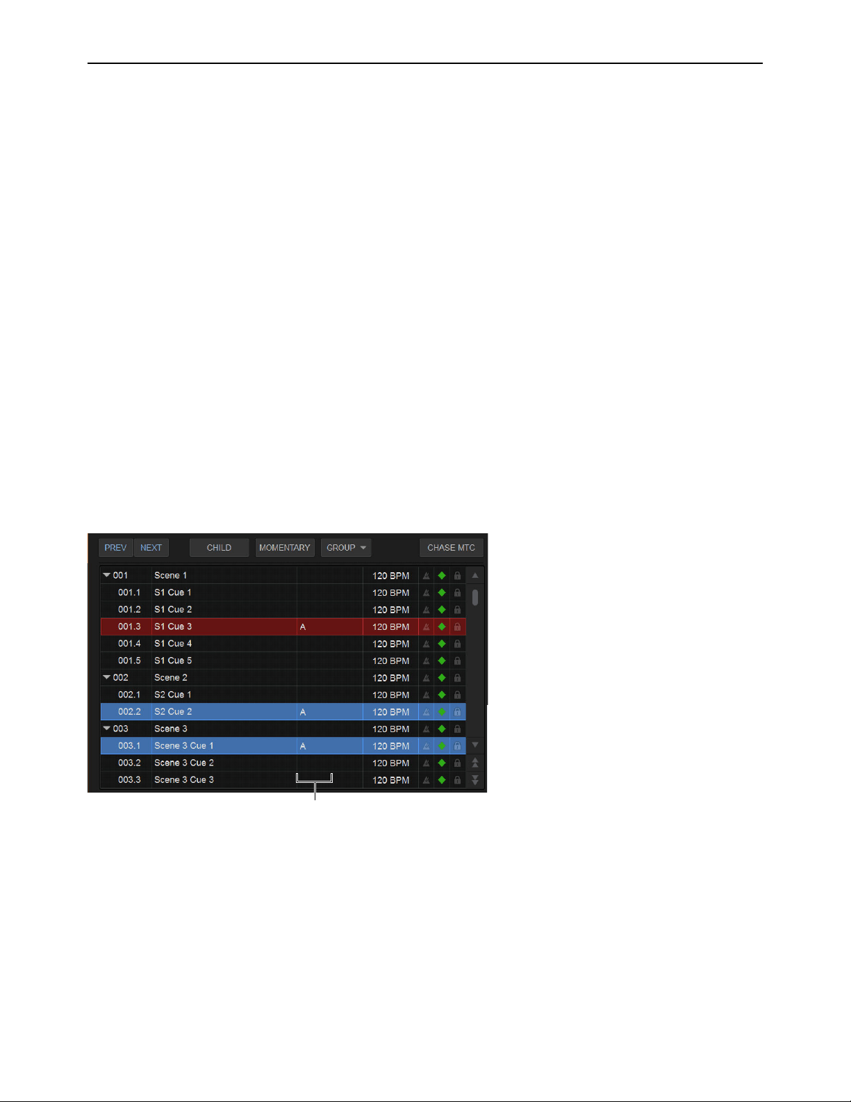
Snapshots 225
Snapshot Groups
You can organize snapshots into Snapshot Groups, to be able to quickly update multiple snapshots simultaneously. A Snapshot
Group can contain one or more snapshots, and snapshots can be assigned to multiple groups.
For example, in a theatrical production you might want to create a Snapshot Group for all cues that include a specific character, and
another group for when that character is wearing a hat or a mask. If you decide you want to use a different EQ setting on a character
mic, you can adjust the EQ in one of the corresponding snapshots. When you Store the change (to update the single snapshot) you
can choose to apply the change to all other snapshots in the group (without having to manually select the other snapshots).
Or in a music performance, you might create a Snapshot Group for all songs where the drummer sings lead. By grouping all the
snapshots for songs when the drummer sings you can increase the level of the lead vocal in one of those snapshots, then choose to
apply the level increase to all snapshots in the same Snapshot Group.
Assigning Snapshots to Groups
To assign snapshots to a snapshot group:
1 Select one or more snapshots in the list, and make sure none of them are locked (you cannot assign locked snapshots to a Snap-
shot Group).
2 Tap the Group selector located just above the list.
The Group selector shows a hierarchical menu. Each top-level choice (Groups A–Z >, Groups AA–ZZ >, Groups BA–BZ > and
so on) provides its own sub-menu of choices (Group: A–Z, Group: AB–AZ, Group: BA–BZ, and so on).
3 Choose a Group to which you want to assign the currently selected snapshots.
The chosen Group (such as A) appears in the list for the selected snapshot(s). (The location of the Group indicator varies de-
pending on the display status of other snapshot attributes such as time code or markers.)
To remove a group assignment:
1 Select the snapshot(s) you want removed from the group.
2 Tap the Group selector and deselect the group from the appropriate sub-menu.
Editing Grouped Snapshots
When you Store, Update, or Edit a snapshot that is assigned to a Snapshot Group you can choose to apply the edit(s) to only the
selected snapshot (Selected Only) or to all other snapshots in the same Snapshot Group(s) (All).
Snapshot List showing three snapshots assigned to Group A
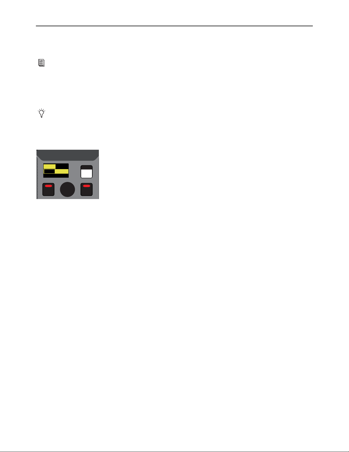
Snapshots 226
Recalling Snapshots
To recall a snapshot, you target the snapshot, scope channels and parameters that are recalled when you recall the snapshot, then
recall the snapshot.
Targeting Snapshots
Targeting a snapshot lets you preview which data types and channels will be affected by that snapshot before recalling it. When a
snapshot is targeted, the on-screen Data Type buttons and Channel Faders update to show the data types and channels enabled for
recall by the snapshot.
To target a snapshot, do any of the following:
Rotate the encoder in the Snapshots section of the MLM so the targeted snapshot is shown in the Snapshot display.
On the Snapshot page of the external screen, select the snapshot name in the Snapshot list.
Type the number or name of the snapshot on the keyboard.
Press the Home/End, Page Up/Page Down, and Up/Down Arrow keys on the keyboard to navigate the Snapshot list.
The targeted snapshot is shown in the Snapshot display on the MLM, highlighted in red in the external screen Snapshots list, and
shown in red in the external screen Status display.
You can also target and recall snapshots using the
Snapshot Controls on the MLM.
Preview mode lets you take the system controls offline to recall and edit snapshots without affecting the current mix. See
Pre-
view Mode.
Snapshots section of the MLM
VENUE | S6L
Recall
Store
Preview
001/011
reset all inputs
S1Cu2
001 3
P:S1C1
N:S1C3
S1Cu3
S1Cu2
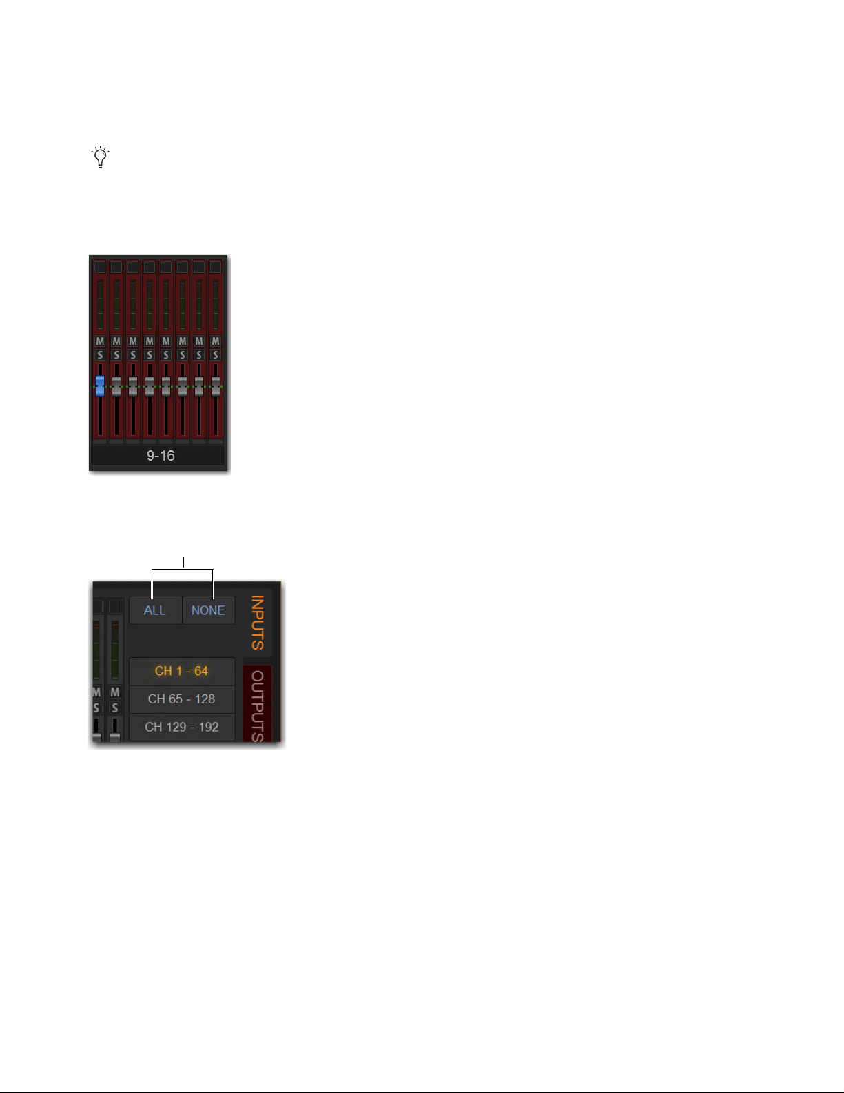
Snapshots 227
Scoping Channels and Parameters
When you create a snapshot, it captures the current state of all system settings. When recalling a snapshot, you can scope the chan-
nels you want affected (using the Channel Scope controls), and the parameters that are recalled (using the Data Type Scope but-
tons).
To scope channels for recall:
1 On the Snapshots page of the external screen, select the individual fader strips so that they are displayed in red.
2 To select channels in banks of eight, select the channel numbers at the bottom of the on-screen fader strips so the channels.
3 To select all channels, select the ALL Channel Scope Action button.
4 To clear all channels from the scope, select the NONE Channel Scope Action button.
5 The fader strips for scoped channels are highlighted in red.
You can rescope snapshot data at any time. You do not need to store/overwrite a snapshot if you change the scope of a snapshot.
A bank of eight channels scoped for snapshot recall
ALL and NONE Channel Scope Action buttons

Snapshots 228
To scope parameters for recall:
1 For each parameter of the scoped channels you want affected when the snapshot is later recalled, select the corresponding Data
Type button so that it is scoped (displayed in red).
2 To scope all parameters, select the ALL button.
3 To clear all data types from the scope, select the NONE button.
Recalling Snapshots
You can do the following when recalling snapshots:
• Target and instantly recall successive snapshots (next or previous)
• Target first, then recall one or more snapshots
• Select multiple snapshots and recall them all sequentially
• Target snapshots, change Data Type or Channel Scope settings, then recall.
Confirm Snapshot Recall
When the Confirm Snapshot Recall setting is enabled in the Options > Snapshots tab, a warning dialog appears asking to con-
firm the operation.
Layouts included in the scope of a snapshot
ALL/NONE Data Type Scope buttons
When you create a new snapshot it automatically inherits the channel and data type scope of the currently targeted snapshot.
Undoing snapshot recall commands might cause audio to be interrupted. Use Undo with caution in performance.
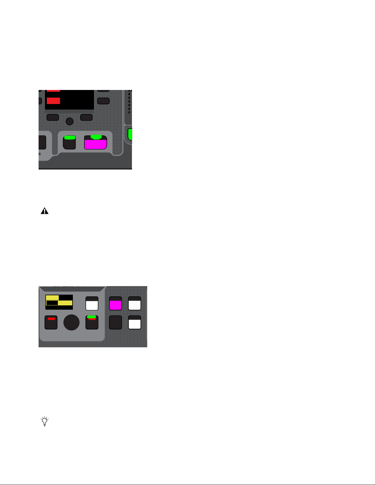
Snapshots 229
Recalling Successive Snapshots Instantly
You can instantly recall successive snapshots in the Snapshots list using the S6L control surface or the external screen. This com-
mand references the currently recalled snapshot, not the targeted snapshot.
To instantly recall successive snapshots using the control surface:
On the MLM, press the PREV or NEXT switch, under the Right Soft Keys. The switches are lit when a next and/or previous
snapshot is available to recall.
To instantly recall successive snapshots on the external screen:
Select the PREV or NEXT button at the top of the Snapshots list.
Targeting Before Recalling Snapshots
You can target then recall a snapshot using the S6L control surface or the external screen.
To target and then recall a snapshot using the control surface:
1 Rotate the encoder in the Snapshots section of the MLM so the targeted snapshot is shown in the Snapshot display.
2 (Optional) Set the scope of the snapshot.
3 Press the lit Recall switch.
To target and then recall a snapshot using the external screen:
1 Select the snapshot name in the Snapshot list.
2 (Optional) Set the scope of the snapshot.
3 Select the Recall button on-screen.
Prev/Next Snapshot switches
The Snapshot Recall buttons combine target and recall actions in one step, causing the previous or next snapshot to be instantly
active. These buttons cannot be used to preview snapshots before recalling them.
Snapshots section of the MLM
Snapshot Recall can also be triggered by a footswitch or any number of other functions using events. For more information, see
Events.
F5
NEXT
PREV
Mute Group 5
Mute Group 6
M5
M6
VENUE | S6L
Home Config
Recall
Store
SNAPSHOTS
Talk
Back
Over
Write
Preview
001/011
reset all inputs
S1Cu2
001 3
P:S1C1
N:S1C3
S1Cu3
S1Cu2
VENUE | S6L
Home Config
Recall
Store
SNAPSHOTS
Talk
Back
Over
Write
Preview
001/011
reset all inputs
S1Cu2
001 3
P:S1C1
N:S1C3
S1Cu3
S1Cu2

Snapshots 230
Managing Snapshots
You can manage snapshots in the list by storing, locking, clearing, duplicating, deleting, or moving them. When any of these ac-
tions are performed while multiple snapshots are selected, on a Parent snapshot, or on a snapshot that is a member of a Snapshot
Group, you can choose to apply the action to only the selected snapshot or all related snapshots.
Storing Snapshots
You can modify the contents of an existing snapshot, overwriting it with new settings, using the Store command. It is not necessary
to recall a snapshot to store it. You can undo Store commands.
To store the current state of the system in an existing snapshot:
1 Set all parameters as you want them to be stored in the snapshot.
2 Select the snapshot in the Snapshot list.
3 Select the Store button on-screen.
4 Set the scope by doing the following:
• For each parameter you want to be affected when the snapshot is recalled, select the corresponding Data Type button so that
it is scoped (displayed in red).
• For each channel you want affected when the snapshot is recalled, select its on-screen channel fader so that it is scoped (dis-
played in red).
Locking Snapshots
Snapshots can be locked to prevent them from being accidentally altered, overwritten or deleted. Locked snapshots can be selected,
recalled, moved and duplicated. They cannot be overwritten, renamed, rescoped or otherwise changed. New and duplicated snap-
shots default to unlocked. Lock status can be changed at any time, including while in Preview mode.
To lock a snapshot:
1 Go to the Snapshots page and select the Main tab.
2 In the Snapshot list, select the padlock icon at the far right of the row for any item. The padlock icon illuminates to indicate the
snapshot is now locked.
3 Select multiple snapshots using Multi-Select or the Shift key to lock or unlock multiple snapshots at once.
Once locked, operations that would otherwise affect the snapshot cause the Status display and channel LCDs and Snapshot LCD
to temporarily show a message reminding you that the operation cannot be applied while the snapshot is locked.
To unlock a snapshot:
Select the lit padlock icon in the row for that snapshot.
Undo and Locked Snapshots
You can undo locking or unlocking a snapshot. When toggling lock status for a selection of more than one snapshot, the entire op-
eration creates a single undo point (it does not track and provide undo for each individual snapshot in the selection).
Snapshot lock controls
Undo can revert snapshots to “unlocked” status. For example, if you change the scope of an unlocked snapshot, lock the snap-
shot and then use Undo, the snapshot is unlocked. Pressing Undo one more time will revert the snapshot to its original scope.

Snapshots 231
Locking Snapshots and MIDI Record
When using the MIDI Record feature, all MIDI data captured up to the point a snapshot is locked is preserved. If the MIDI Record
operation is still active at the time the snapshot is locked, record mode is exited, the REC button becomes unavailable for that snap-
shot, and subsequent incoming MIDI messages are not captured.
Available Operations with Locked Snapshots
The following table details which operations can or can not be performed on a locked snapshot.
Operation Allowed while Locked Disallowed while locked
Select/target snapshot X
Recall snapshot X
Duplicate snapshot X
Re-sequence in snapshot list by:
• Dragging in snapshot list
X
• Manually editing sequence number
X
• Re-sorting by time code
X
Overwrite (Store to locked snapshot) X
Update changes X
Parent/Child (designate) X
Momentary/Sequential (designate) X
Group (assign or unassign) X
Apply Edit mode changes X
Clear X
Delete X
Modify Scope X
Modify User Aux Scope X
Add/Modify stored MIDI data X
Add/Modify stored Plug-In data X
Add/Modify stored Media date X
Modify Notes X
Modify X-Fade time X
Modify Snapshot Name X
Modify Time Code Location X
Toggle Time Code Enable X
Undo changes X

Snapshots 232
Clearing Snapshots
The contents of a snapshot can be cleared while keeping the snapshot in the Snapshot list and retaining its MTC information. This
lets you maintain a placeholder that you can use later to store new data. You can undo Clear commands.
To clear the contents of a snapshot:
1 Select the snapshots you want to clear.
2 Select the Clear Snapshot Command button.
3 In the dialog box, select Clear to confirm. Cleared snapshots are renamed “<Untitled>.”
Duplicating Snapshots
Snapshots can be duplicated from the Snapshots list. You can undo Duplicate commands.
To duplicate snapshots:
1 Select the snapshots you want to duplicate.
2 Do one of the following:
•Select Dup (Duplicate).
– or –
• Touch-and-hold the snapshot name and choose Duplicate.
A copy of each selected snapshot is placed after the selection, with a plus sign (+) appended to the original snapshot name.
If multiple snapshots are selected in the list, the new (duplicate) items are added below their original source snapshots.
Deleting Snapshots
Snapshots can be deleted from the Snapshots list. You can undo Delete commands.
To delete snapshots:
1 Select the snapshots you want to delete.
2 Do one of the following:
•Select Del (Delete).
– or –
• Touch-and-hold the snapshot name and choose Delete. The snapshots are removed from the Snapshots list, and succeeding
snapshots are renumbered.
Moving Snapshots
Existing snapshots can be rearranged in the Snapshots list. When you move one or more snapshots, they are automatically renum-
bered in the list, but MTC values are left unchanged. You can undo a snapshot move.
To move one or more snapshots:
1 Select one or more events in the Snapshots list.
2 Touch any selected snapshots and drag them to a new location in the list. As you move items, a white line appears indicating the
destination.
3 Release your finger to drop the snapshots at the desired location in the list. Snapshots that are moved will be adjacent regardless
of their original locations relative to each other (whether adjacent or non-adjacent). Snapshots will be renumbered as necessary
according to the new sequence of events.

Snapshots 233
Importing Snapshots
Snapshots from other Show files can be imported into the currently loaded Show file in the Filing > Load/Save tabs.
For more information, see
Import Snapshots and Events.
Making Changes to Snapshots
There may be situations where you need to change specific parameters in existing snapshots while leaving other parameters un-
changed.
For example, if a guitarist changes instruments in the middle of a tour it might be necessary to change levels and EQ on the guitar
channel in all the snapshots in a show. Snapshots provides the following modes to accommodate these types of situations:
Edit Mode
Lets you capture individual control changes while you mix, and apply those changes to one or more pre-existing snap-
shots as absolute or relative changes. For example, you could enter Edit mode the first time a guitarist uses a new guitar in rehearsal.
When you are satisfied with your settings you can apply them (in absolute or relative fashion) to update other snapshots. See Using
Edit Mode.
Update Mode
Lets you update data in pre-existing snapshots after you've already made changes and decided you want to keep
them. While Edit mode requires you to know ahead of time that you will be updating snapshots, Update mode lets you decide to
update other snapshots with current settings after making adjustments to your mix. For example, if its the third consecutive night
you’ve reached to increase gain on the DI channel for a new guitar, you could use Update mode to quickly take the gain increase
you just made and apply it to other snapshots. See
Using Update Mode.
Using Edit Mode
Edit mode is a powerful way to update specific parameters across multiple snapshots without overwriting any settings you want to
preserve. By entering Edit mode before making adjustments, you can edit a single control or any number of controls, and your
changes are tracked from the point Edit mode was entered.
Absolute and Relative Edits
Changes can be applied to one or more selected snapshots as absolute or relative values. Any parameter can be edited in absolute
fashion; all dB parameters can be edited in relative fashion.
Examples of Absolute and Relative Edits
Absolute
Changing a fader level from 0 dB to –3 dB and applying that change as Absolute results in that fader being set identically
to –3 dB in all selected snapshots.
Relative
Changing a fader level from 0 to –3 dB and applying that change as Relative results in that fader being reduced by that
amount in all selected snapshots, or 3 dB relative to the value previously stored in the snapshot(s). For example, a channel previ-
ously at –6 dB would be changed to –9 dB.
Making Relative Changes with Mixed Data Types
If a combination of dB and non-dB parameters (such as gain and EQ frequency) are edited and applied in relative fashion, the dB
parameters are adjusted as relative (delta) changes and the non-dB are applied as absolute changes.
In VENUE software versions 5.6 and lower, Import Snapshots was available via right-click. Beginning in VENUE software
version 5.7, use the Import button instead.
Events-driven recall of snapshots is disabled while in Edit or Update mode. For more information, see
Events.
The ability to edit a single control in Edit mode provides more selectivity than Update mode.
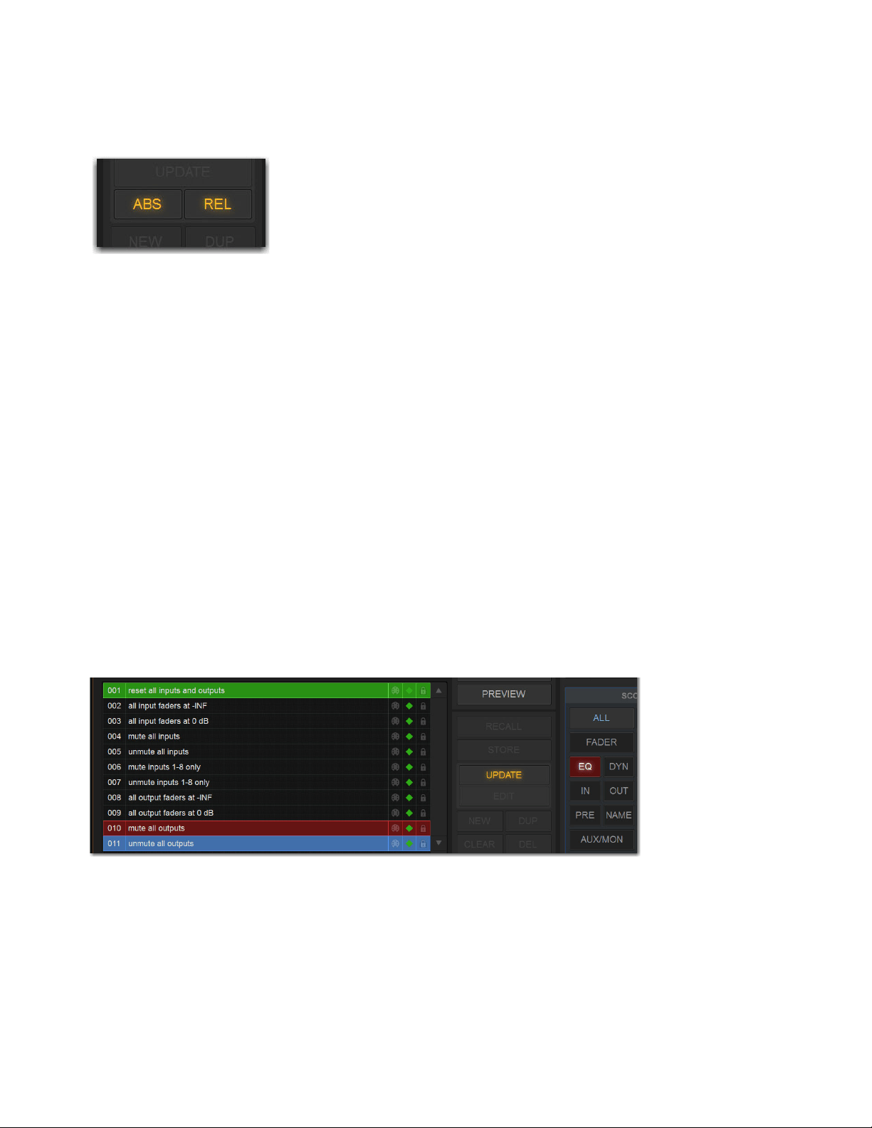
Snapshots 234
To update specific parameters in existing snapshots using Edit mode:
1 Go to the Snapshots page and select the Main tab.
2 Select the Edit button to enter Edit mode. The Edit button changes into two smaller flashing buttons: Abs, and Rel. The system
begins tracking all changes while you make them.
3 Adjust any combination of scopable parameters.
4 Select the snapshot(s) to which you want to apply your edits.
5 Select either of the flashing buttons Abs (for Absolute) or Rel (for Relative). You can cancel Edit mode by pressing the Cancel
switch on the control surface, selecting the Cancel button on-screen, or by pressing the ESC key on your computer keyboard.
The selected snapshots are updated according to your changes and your choice of Absolute or Relative edit.
Using Update Mode
You can use the Update command to capture changes and apply them to existing snapshots. Update mode is most useful when you
realize during the course of mixing that you want to capture your current settings to use in other snapshots. You can undo Update
commands.
To update specific parameters in existing snapshots:
1 Make sure the channel is set as needed.
2 Select Update. The current data and channel scope is cleared.
3 Set the scope to reflect only those parameters you want to update by doing the following:
• For each parameter you want to update, select the corresponding Data Type button so that it is scoped (displayed in red).
– and –
• For each channel you want to update, select the channel so that it is scoped (displayed in red).
4 Select the snapshot or range of snapshots you want to update in the Snapshots list.
5 Select Update. The scoped parameters are updated in the selected snapshots.
Absolute (ABS) Relative (REL) Edit mode buttons
Updating an EQ setting for a channel

Snapshots 235
Undoing Snapshot Commands
The Undo function returns the system to the state immediately before the last snapshot command. Undo is multi-level (up to 100),
is available while in Preview mode and after performing an Edit or Update mode action.
To undo a snapshot command:
Select the Undo button in the Snapshot commands section.
Disabling Snapshots
You can temporarily disable the storage and recall of all snapshots. While snapshots are globally disabled, you can target snapshots
in the Snapshots list to preview their properties, but you cannot recall them.
To disable all snapshots:
Select the Disable button in the Snapshot commands section.
Suspend MTC Recall
To disable MTC or LTC recall of individual snapshots in the list:
1 Select the green Enable icon in the row for the desired snapshot so that it is unlit.
2 Select the Disable/Enable icon again to re-enable the snapshot.
Undoing snapshot recall commands may cause audio to be interrupted. Use Undo with caution in performance.
If the Undo button is dimmed, Undo is not available.
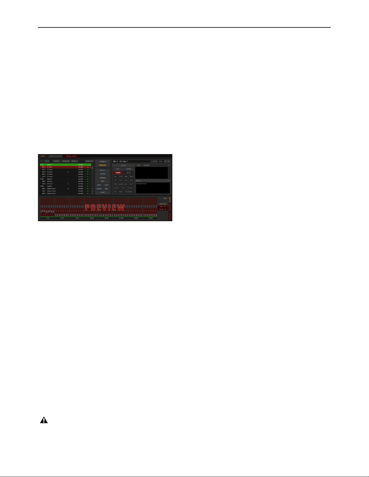
Snapshots 236
Preview Mode
Preview mode lets you recall, store and edit snapshots without affecting the current mix.
When enabled, Preview mode takes the system offline from the live audio mix so you can “work ahead” during a rehearsal, per-
formance or event to preview upcoming snapshots and edit them as needed. Any control that can be stored and recalled by snap-
shots is available while in Preview mode, and you can also modify the Snapshot list. Once you are done previewing or editing snap-
shots, you can store your changes to update the existing snapshots with your changes.
Using Preview Mode
The basic workflow for using Preview mode is as follows:
1 Make sure your active mix is set as desired, and make sure the rehearsal, event or performance has an upcoming opportunity for
you to go offline.
2 Enter Preview mode by selecting the Preview button on the main Snapshots page. The word “PREVIEW” flashes in red across
the screen for confirmation, as do all input and output channel strip displays.
3 Do any of the following:
Edit the Snapshots List
Reorder snapshots in the list, if desired, by touching-holding-and dragging them. Changes to the order of
items in the Snapshots list may affect the current active mix if the affected snapshots rely on MIDI or MTC triggering. (For more
information, see
Changing Settings in Preview Mode.)
Create a New Snapshot
Adjust settings as desired and create a new snapshot by selecting New. (See Creating New Snapshots.)
Recall and Edit an Existing Snapshot
Recall a snapshot to preview its settings and make any adjustments necessary, being sure to
re-store the snapshot before exiting Preview mode. Storing a snapshot in Preview mode does not affect previously stored MIDI or
Plug-in data (if any).
Edit Channel and Scope Settings
Edit any channel settings, parameters, or scope associated with the snapshot being previewed.
The Snapshots page displays the current snapshot name in italics to indicate that at least one parameter has been changed, and the
Channel Faders show you the previous level for each channel in bright red. Scope Data Type buttons and Channel Scope function-
ality remain live and active at all times (in other words, changes made to these controls while in Preview mode will remain once
Preview mode is exited).
Add and Edit MIDI, Plug-In Data
To add MIDI, or plug-in data associated with the snapshot, select the Add button in the MIDI or
Plug-Ins snapshot list, or select the options in the Media list. For more information, see
Adding Plug-In Data to Snapshots.
4 \To undo an action made while in Preview mode, select the Undo button on-screen. (For more information about Undo in Pre-
view mode, see
Making Changes to Snapshots.)
5 To update the currently previewed snapshot but remain in Preview mode, press or select Store.
6 Continue previewing and editing settings as needed (all snapshot functions are available in preview mode).
7 When you are finished and need to exit Preview mode, press F1 (or select the on-screen Preview button).
Preview mode
Exiting Preview mode without storing will discard the changes made while in Preview mode (Preview mode is cleared each time
you exit). You must explicitly store changes to update the associated snapshots.

Snapshots 237
Undo and Preview Mode
In Preview mode, you can Undo actions applied to the Snapshot List (such as Recall, Store, New and Duplicate) without affecting
the online mix.
Changing Settings in Preview Mode
The system tracks any changes to settings or to the Snapshot list while in Preview mode, but only Snapshot list actions create an
Undo point. Choosing Undo will undo the last action you took while in Preview mode, up to a maximum of 100 levels of Undo.
Any changes made after the last Preview action are also undone (the Snapshot screen is returned to its exact state prior to the action
that created the Undo point).
Changing the Snapshot List in Preview Mode
Changes made to the Snapshot list are automatically tracked and available for Undo, regardless of whether Preview mode is en-
abled or not. This includes any Recall of snapshots triggered by incoming MIDI or MTC while in Preview mode.
For example, if a MIDI Snapshot Recall occurs while you are in Preview mode, the online mix will be updated with that snapshot.
Pressing Undo immediately after that Recall will undo that Snapshot recall and revert the online mix to its state prior to the Undo.
Consider turning off the Chase MTC option while in Preview mode to disable all MIDI recall of snapshots. In addition, you can al-
ways use the History feature to recover from any unexpected results.
Changing MIDI, Plug-In, and Media Data in Preview Mode
Changes made to MIDI, Plug-In, and Media data cannot be undone. For more information, see
Adding MIDI and Plug-In Data
to Snapshots.
Available and Unavailable Functions in Preview Mode
In order to maintain essential mix indicators and controls while in Preview mode, not all functions are taken offline.
The following sections detail what is and what is not available during Preview mode.
Always Active
Certain essential mix functions remain live and active at all times, regardless of whether Preview mode is enabled. The following
vital mix functions continue to affect or be affected by the adjustments made to settings:
• Metering
•AFL/PFL
• Dynamics Key Listen
• Monitoring level, Headphone level and Monitoring bus Delay
• Talkback, Osc and 2-Track
• Mute Groups (recall only)
• Recall Safe
• MIDI snapshot Recall, Chase MTC and Disable (Snapshots)
• Snapshot list and Recall Safe (deleting, adding, or editing snapshots are/will be reflected online and affect the mix)
• History (auto-save)
Recall Safe in Preview Mode
The Recall Safe settings are global, and are applied to filter snapshot data regardless of the current operating mode. For details on
Recall Safe and other automation safe features, see
Recall Safe.
Multiple levels of Undo are available.
Take advantage of Tool Tips in the banner display to confirm what action the Undo button will revert. See
Undoing Snapshot
Commands.

Snapshots 238
Available and Editable in Preview Mode
Almost all system functions, such as selecting channels and banking faders, are available in Preview mode.
Not Available in Preview Mode
The only controls not available while in Preview mode are those controls which are not able to be stored or recalled via snapshots.
In addition, Config mode options are unavailable in Preview mode.
Unavailable functions include the following:
• Make Stereo, or Split to Mono
• Move channels
• Input channel Gain Guess
• Input channel Input Direct switch
• Insert mode (plug-ins cannot be edited)
• Enabling or disabling sample rate conversion
Config Mode
Config mode is not available while in Preview mode. Pressing the Config switch (or double-selecting the Config/Show mode icon
on-screen) displays a dialog box in which you can choose to “Exit Preview” (return to online mix, in Config mode), or “OK” (re-
main in Preview mode).
The system automatically switches to Show mode if Config mode is active at the time Preview mode is entered.
Plug-Ins and MIDI Data in Preview Mode
In Preview mode, plug-ins and MIDI data operate in a similar way as when using the standalone software.
You must explicitly add or update plug-ins and MIDI data to update snapshots, whether or not Preview mode is enabled. You can
do this from the main Snapshot page, or (for plug-ins) from the plug-in racks.
Only those controls that can be stored and recalled via snapshots are available for offline previewing and editing.
These functions are neither available for offline access in Preview mode, nor do they remain active (online) while in Preview
mode. To adjust any of the above settings, you must exit Preview mode.
Updating plug-in data in an associated snapshot from the plug-in view

Snapshots 239
Plug-Ins in Preview Mode
Recalling a snapshot that contains plug-in data affects the offline (Preview) routing and bypass state of the plug-in only; the online
plug-in parameter settings are not recalled, and the online mix is not affected.
The following plug-in functions are available offline in Preview mode:
• Plug-in routing can be changed
• Plug-in rack view can be changed
• Plug-ins can be added to a snapshot to capture its current online parameter settings and (Preview mode) routing
The following plug-in functions are not available while in Preview mode:
• Plug-ins cannot be added to or removed from rack slots
• Plug-in presets cannot be recalled or saved
• Plug-in parameters cannot be changed (you cannot open plug-in windows while in Preview mode)
• Plug-ins cannot be installed
MIDI in Preview Mode
Incoming MIDI or MTC continues to trigger snapshot recall while in Preview mode. However, MIDI messages stored to snapshots
are not sent out when a snapshot is recalled in Preview mode. For more information, see
Adding MIDI Data to Snapshots.
MTC/LTC and Other Online Event Triggers
While in Preview mode, triggers that occur in the online state of the system are executed, including MTC-or LTC-driven recall of
snapshots. Triggers caused by changes to the offline (Preview) controls are ignored and do not cause events to occur. For more in-
formation, see
Events.
For more information, see Adding Plug-In Data to Snapshots.
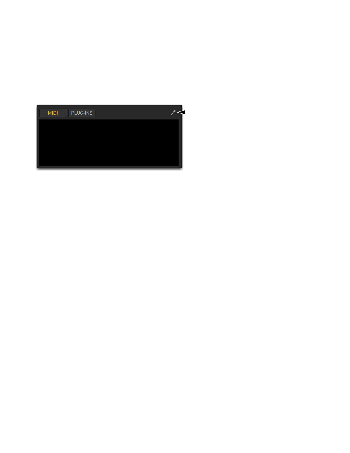
Snapshots 240
Adding MIDI and Plug-In Data to Snapshots
You can add MIDI and plug-in data to snapshots using the MIDI/Plug-In list. Open the list to add and edit data. You can expand
the list for a larger view of list items.
To open the MIDI/Plug-Ins list:
On the Snapshots page, select the MIDI or PLUG-INS button.
To expand the To open the MIDI/Plug-Ins list:
Select the Expand button.
Adding MIDI Data to Snapshots
When the MIDI data type is scoped for a snapshot, any stored MIDI messages are sent when the snapshot is recalled.
The following MIDI messages are supported and available in the MIDI list:
• Note Off
•Note On
• Poly Key Pressure
• Control Change
• Program Change
• Channel Pressure
• Pitch Bend
• MIDI Machine Control Stop
• MIDI Machine Control Play
• MIDI Machine Control Fast Forward
• MIDI Machine Control Rewind
• MIDI Machine Control Eject
• MIDI Machine Control Chase
• MIDI Machine Control Pause
• MIDI Machine Control Locate
When the MIDI data type is scoped for a snapshot, its MIDI messages are sent when the snapshot is recalled.
No MIDI message data is captured when a snapshot is first created. MIDI messages are added to existing snapshots directly from
the MIDI pop-up menu. You can store up to 20 MIDI messages in each snapshot.
MIDI/Plug-Ins List Expand button
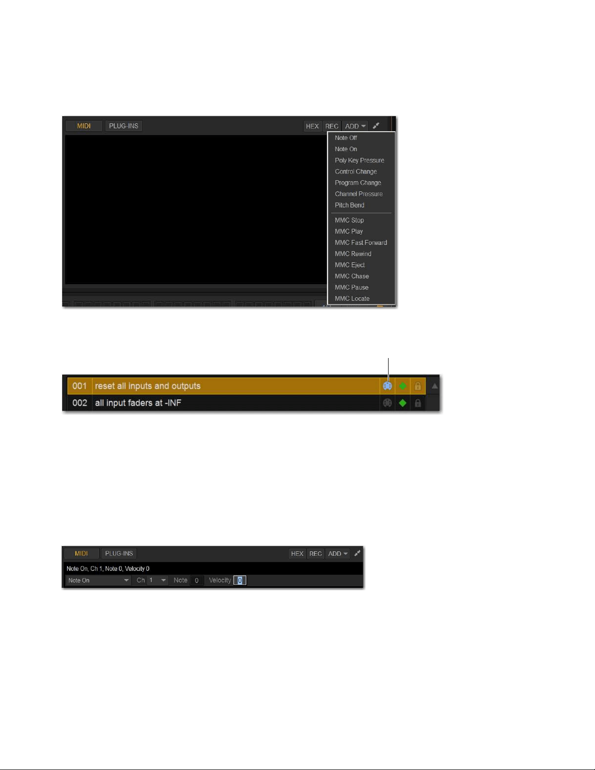
Snapshots 241
To add a MIDI message to a snapshot:
1 Target the snapshot you want to modify.
2 Select the Expand button.
3 Select Add and choose a message from the pop-up menu.
The MIDI lights in the Snapshots list for each snapshot that contains MIDI messages.
To record incoming MIDI data to a snapshot.
1 Select REC.
2 Send a supported MIDI command.
3 Select REC again when done.
To edit a MIDI message in the MIDI list:
1 Double-select the message text to display the pop-up menu bar for the message.
2 Choose the message name and send channel or device ID from the pop-up menus.
3 Enter the message values in the text fields or drag up or down across the text field to change the values.
4 Select in the MIDI list area to dismiss the pop-up menu bar.
To remove a MIDI message from a snapshot:
Touch-and-hold the MIDI message in the MIDI list and choose Delete.
Snapshot MIDI pop-up menu
Lit and unlit MIDI icons in the Snapshots list
Editing a MIDI message in the snapshot MIDI list
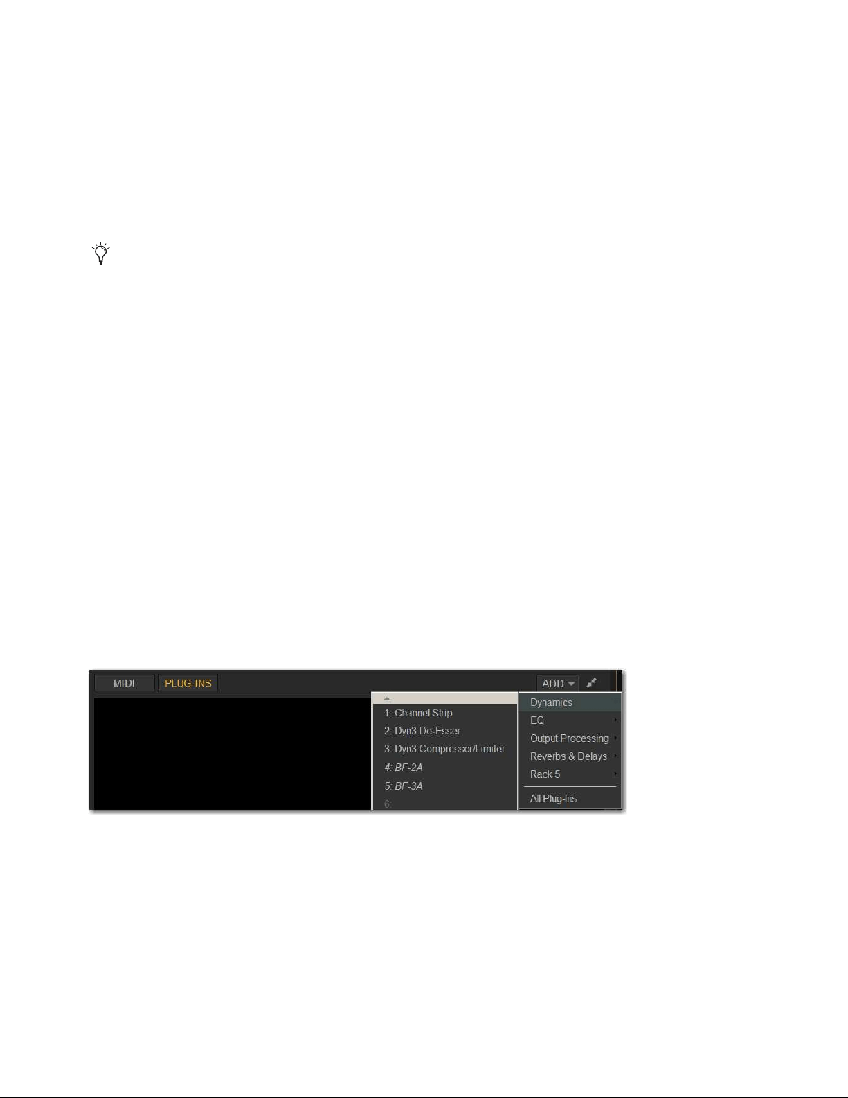
Snapshots 242
Viewing MIDI Messages in Hexadecimal Format
You can toggle the view of MIDI messages in the MIDI list between hexadecimal and decimal formats.
To toggle the view format of the MIDI list:
Select the Hex button in the MIDI/Plug-Ins list header.
Safing MIDI Message Output
You can temporarily disable output of embedded MIDI messages so that they are not sent when a snapshot is recalled, even when
the MIDI data type is scoped.
To safe MIDI message output on-screen:
1 Go to the Snapshots page and select the Recall Safe tab.
2 Select the MIDI global output Safe button above the parameter matrix so that it lights.
Adding Plug-In Data to Snapshots
When the Plug-In data type is scoped for a snapshot, plug-in routing, in/out state, and settings are recalled with the snapshot. (Add-
ing or changing plug-in side-chain routing is not supported in snapshots.)
The Snapshots Plug-Ins list lets you select multiple plug-ins and add, remove and update them simultaneously across one or more
snapshots. Multiple snapshots can be selected, and others can be added to or removed from the selection, at any time prior to add-
ing, removing, or updating plug-ins and snapshots.
No Plug-In data is captured when a snapshot is first created. Plug-In data is added to existing snapshots from the Plug-Ins list or
from the Plug-In rack.
Adding Plug-Ins to Snapshots
To add a plug-in to one or more snapshots from the Snapshots page:
1 Select one or more snapshots in the Snapshots list.
2 Select the Expand button in the MIDI/Plug-Ins list to expand the Plug-In list.
3 Select the ADD button within the Snapshot Plug-Ins list and select a plug-in (or All Plug-Ins) from the menu.
To add a plug-in to snapshots from the Plug-Ins page:
1 Select one or more snapshots in the Snapshots list.
2 Go to the Plug-Ins page.
3 Select the Snapshots menu for the plug-in to be added and choose Add This Plug-In To Selected Snapshots. The selected
plug-in is added to the currently targeted snapshot, as well as all other snapshots within the multi-selection.
Snapshots within the multi-selection that already contained the plug-in being added are unaffected and preserve any previously
stored settings.
MIDI output is automatically suspended while in Preview mode.
Snapshot Plug-In list
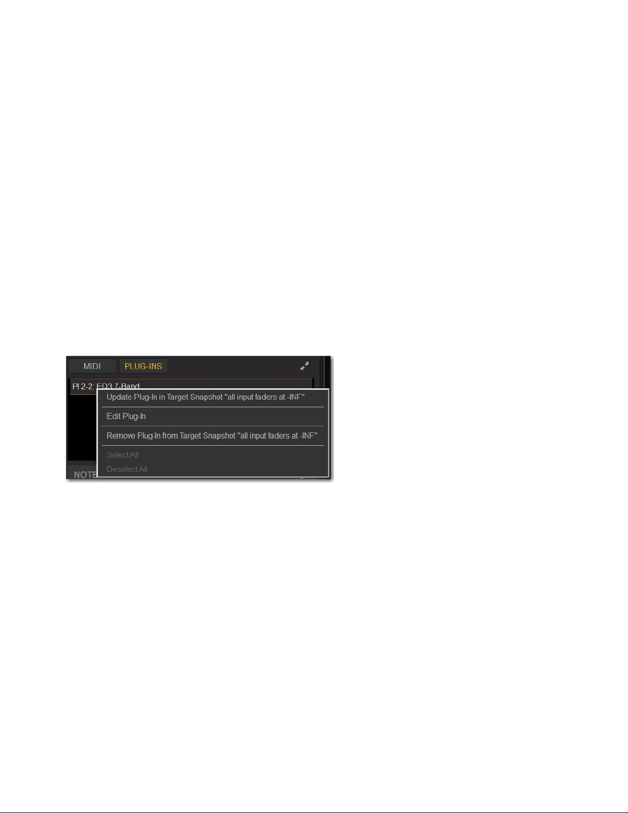
Snapshots 243
Removing a Plug-In from Snapshots
To remove a plug-in from snapshots from the Snapshots page:
1 Select an individual snapshot, or create a multi-selection of snapshots in the Snapshots list.
2 Select the Snapshots Plug-Ins icon to show the Snapshots Plug-Ins list.
3 Touch-and-hold a plug-in within the plug-in list of the currently targeted snapshot and choose Remove This Plug-In From Se-
lected Snapshots.
To remove a plug-in from snapshots from the Plug-Ins page:
1 Select one or more snapshots in the Snapshots list.
2 Go to the Plug-Ins page. All plug-ins that are associated with any of the currently selected snapshots are identifiable by a red
Snapshot selector.
3 Select the red Snapshot selector for the plug-in to be removed and choose Remove This Plug-In From Selected Snapshots.
The selected plug-in is removed from the currently targeted snapshot, as well as all other snapshots within the multi-selection. Only
snapshots within the multi-selection that contain the selected plug-in are affected.
Updating a Plug-In Across Snapshots
To update a plug-in across snapshots from the Snapshots page:
1 Select one or more snapshots in the Snapshots list.
2 Select one or more plug-ins (shift-select) within the plug-in list of the currently targeted snapshot
3 Touch-and-hold the desired plug-in within the plug-in list and choose Update Plug-In In Selected Snapshots.
To update a plug-in across multiple snapshots from the Plug-Ins page:
1 Select one or more snapshots in the Snapshots list.
2 Go to the Plug-Ins page. All plug-ins that are associated with any of the currently selected snapshots are identifiable by a red
Snapshot selector.
3 Select the Snapshot selector for the plug-in to be updated and choose Update This Plug-In In Selected Snapshots.
The selected plug-in is updated within the currently targeted snapshot, as well as all other snapshots within the multi-selection.
Snapshots within the multi-selection that do not already contain the plug-in being added are unaffected.
Editing Plug-Ins
The Snapshot page provides two ways to quickly navigate to a plug-in to edit its routing assignment or parameters.
To edit a plug-in associated with a snapshot:
Double-tap the item in the Snapshot Plug-Ins list. Or, in the Snapshots Plug-Ins list touch-and-hold a plug-in and choose Edit
Plug-In.
Snapshots plug-ins pop-up menu with multiple plug-ins selected in the Snapshots Plug-Ins list
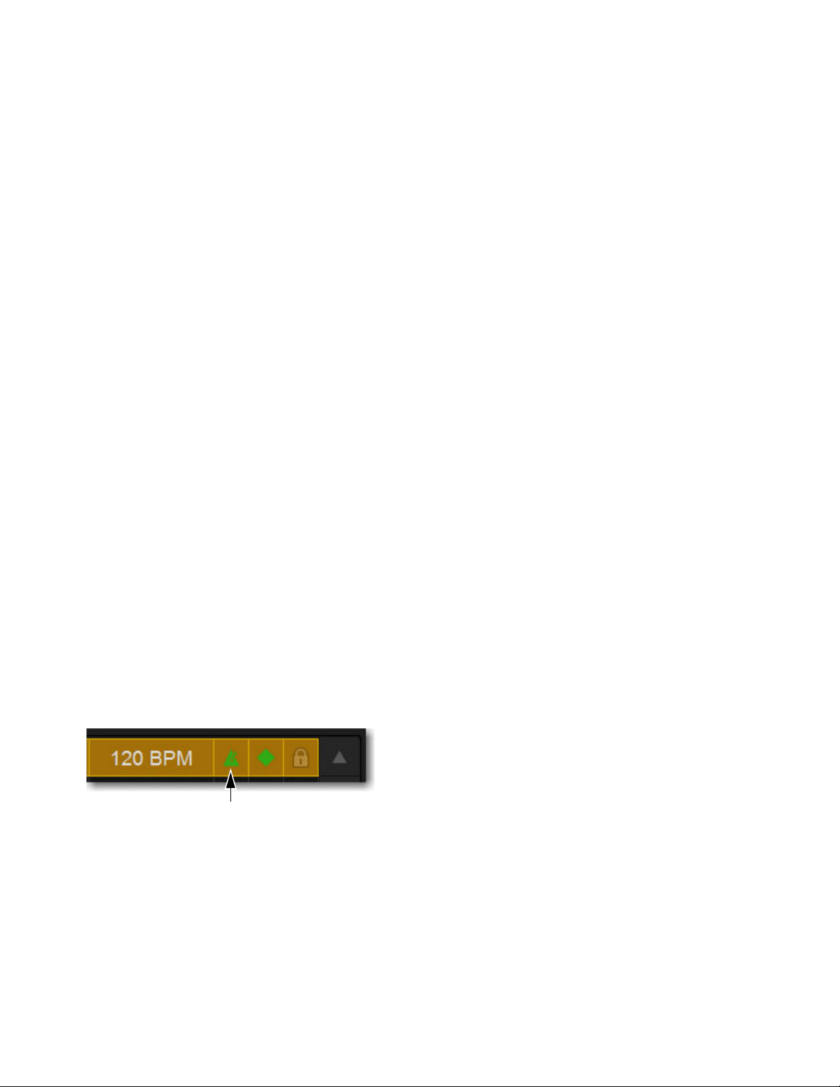
Snapshots 244
Adding Tempo Data to Snapshots
The Snapshots list can be toggled to display Tempo, along with a Tempo On/Off indicator for each snapshot entry.
Storing a tempo with snapshots lets your system tempo change per song or scene. This lets you take full advantage of Tempo Sync
(aka Tap Tempo) to synchronize delay and echo plug-ins. The System Tempo is set on the Options > Misc page. For details on con-
figuring the system tempo and using it to synchronize plug-ins, see
Tap Tempo for Plug-ins.
Displaying Tempo in the Snapshots List
To show Tempo in the Snapshots list:
Touch-and-hold anywhere in the Snapshots list and choose Show Tempo.
Tempo is displayed in BPM (beats per minute) or milliseconds, as set in the Options > Misc page.
To change the units for Tempo display:
1 Go to the Options > Misc page.
2 In the Tap Tempo section, select BPM or ms.
Assigning and Enabling a Tempo
Each snapshot can store a custom tempo value. You can manually enter a custom tempo, or use a shortcut to assign the current Sys-
tem Tempo.
You can use the Tempo Enable icon to enable or disable tempo recall when the associated snapshot is recalled.
To assign a Tempo value to a snapshot manually:
1 In the Snapshots list, double-tap the Tempo value you want to change, then do one of the following:
• From the keyboard, type a new tempo value.
• Press the Up and Down Arrow keys to increase and decrease the selected value.
2 Press Enter or select another snapshot Tempo value to confirm the entry.
To assign the current System Tempo to a snapshot:
1 Make sure Tempo is shown in the Snapshots list.
2 Touch-and-hold and choose the Set Tempo to option, which will display the current System Tempo.
To toggle tempo on/off for each snapshot:
1 Make sure Tempo is shown in the Snapshots list (if not, touch-and-hold any item in the list and choose Show Tempo).
2 Select the Tempo icon. The icon lights when tempo is enabled.
The current tempo and a lit Tempo icon in the Snapshots list

Snapshots 245
Adding Pro Tools Markers Using Snapshots
With VENUE Link enabled, you can set individual snapshots to create a new Marker in the Pro Tools Timeline. While Pro Tools
is recording, whenever that snapshot is recalled, a new Marker is created and named according to the recalled snapshot.
Displaying the Marker Icon
To show Markers in the Snapshots list:
Touch-and-hold anywhere in the Snapshots list and choose Show Markers.
A lit Markers icon indicates that recalling that snapshot will create a new Marker in the Pro Tools timeline when recording.
Snapshot Options
Center Last Recalled Snapshot
The Options > Snapshots page provides a preference setting to always center the Snapshot list on the last recalled snapshot. When
enabled, the
Center Last Recalled Snapshot setting lets you always view the snapshots immediately above and below (prior to
and following) the last recalled snapshot. This setting only affects the scroll position of items in the Snapshot list.
Confirm Snapshot Recall
When this setting is enabled, a warning dialog appears when any snapshot is recalled asking to confirm the operation. When not
enabled, recalling snapshots requires no confirmation.
Enable Strip Control on Snapshots Tab
When this setting is enabled (the default setting), you can adjust channel faders, Safe, Solo, and Mute controls in the strips sections
along the bottom of the main Snapshot tab. When not enabled, these controls cannot be adjusted on-screen (legacy behavior).
Crossfade Time
You can set the X-fade (crossfade) time for the channel faders between snapshots from 0–99.9 seconds, in 0.1 second increments.
This value determines the fade time, or the time it takes for the controls to move to their new positions when a snapshot is recalled.
In addition to channel faders you can optionally enable snapshot crossfade for pan/balance/width,
All other controls are unaffected by the crossfade time, and are updated instantly when a snapshot is recalled. Each snapshot may
be assigned its own crossfade time. In addition, crossfades will continue through a subsequent snapshot recall as long as the cross-
fading channels are not scoped in the incoming snapshot.
Pan, Balance & Width
Enable this setting have channel pan parameters follow snapshot crossfade settings.
Default Crossfade Time
The default crossfade time assigned to new snapshots can be set with this option, with a possible range of 0–99.9 seconds.
To set the Default Crossfade Time:
Go to Options > Snapshots, then under Snapshot General Preferences enter a value or drag in the text box and press Enter.
For more information, see the VENUE S6L Live Recording Guide.pdf.
Snapshot options
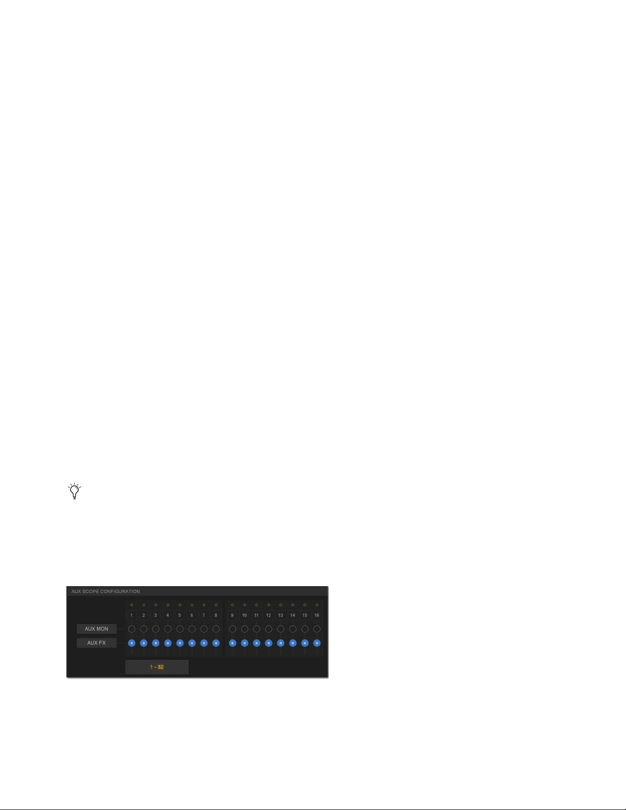
Snapshots 246
Crossfade Bypass
Snapshot crossfades can be up to 99.9 seconds. You can quickly bypass (cancel) a crossfade and immediately advance to the stored
snapshot fader settings in order to speed up rehearsals, or whenever on-stage action moves faster than a programmed crossfade.
To bypass a snapshot crossfade:
Recall the same snapshot at any point during the crossfade. Doing so recalls the entire contents of that snapshot, in addition to
bypassing the crossfade. This is equivalent to recalling the snapshot with an effective crossfade time of 0 seconds. Any scoped
parameters which were manually changed during the crossfade time will be reset to the values stored in the snapshot.
Special Cases for Crossfade Bypass
Incoming MIDI Commands
The snapshot crossfade is not bypassed if a MIDI Program Change message recalling the same snap-
shot is received during the crossfade.
MTC
The snapshot crossfade is not bypassed if a MTC trigger recalling the same snapshot occurs during the crossfade.
Multiple Simultaneous Crossfades
The crossfade can be bypassed for the most recently recalled snapshot only.
Preview Mode
If you enter Preview mode in between Recall commands, the offline (Preview mode) crossfade will be bypassed;
the online crossfade will not.
Pre Settings
Snapshots can be used to recall the preamplifier settings on inputs for all scoped input channels. You can set any of the following
Pre parameters to be recalled by the Pre data type button: Gain, Pad and Phase/polarity, +48V (Phantom Power), HPF corner fre-
quency and in/out state.
To set the Pre parameters recalled by the Pre Data Type button:
1 Go to Options > Snapshots.
2 Under Pre, select the options you want to include. Selected items will be affected when the Pre data type is included in the scope
of a snapshot.
Classifying Aux Sends
You can classify Aux Sends as monitor sends (“Aux Mon”) or as effects sends (“Aux FX”), which lets you scope each type sepa-
rately from the Snapshots tab of the Options page.
To classify Aux Sends for snapshot scope:
1 Go to the Options page and select the Snapshots tab.
2 For each Aux Send bus or bus pair, select the Aux Mon or Aux FX buttons to classify it as a monitor send or effects send, re-
spectively.
Aux Pre/Post State
Select this option to include the pickoff point pre-fader or post-fader state of each Aux Send in snapshots.
This option is only a means of organizing Aux Sends for snapshot control, and does not directly affect Aux bus operation. See
also
User Aux Scope.
Classifying Aux Sends
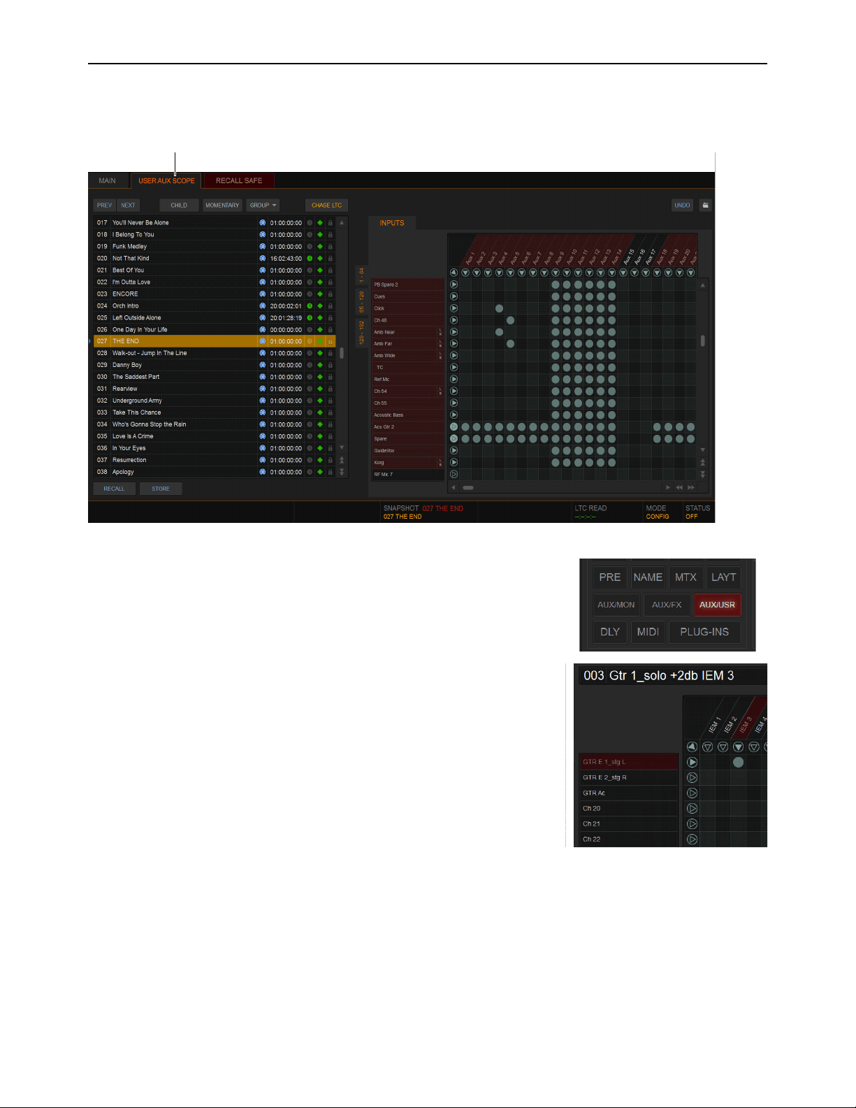
Snapshots 247
User Aux Scope
The User Aux tab provides a grid that lets you scope individual Aux Sends per Input channel, to specify which Aux Sends on each
input to include or exclude when storing and recalling snapshots.
In addition, the Data Type Scope button AUXUSR (Aux User) is provided in the main
Snapshots tab. This button enables (includes) or disables (excludes) User Aux grid settings
from being recalled by snapshots.
User Aux Scope Example
The ability to include or exclude individual Auxes in snapshots has many applications, in-
cluding monitor mixing.
For example, you can configure a single snapshot to raise the monitor level of a specific in-
put such as lead guitar only in the mix for the lead guitarist. By scoping only the Aux feed-
ing the guitarists monitor mix on the guitar input channel, recalling a snapshot with that
Aux raised a few dB will not affect the guitar level in other performers’ monitors.
The example image to the right shows the User Aux Scope grid configured for this exam-
ple. A snapshot “003 Gtr 1_Solo +2dB IEM 3” has been stored with only the Aux “IEM 3”
scoped for the input channel “GTR E 1_stg L.”
User Aux Scope tab (at top) and grid (at right) shown in the Snapshots tab
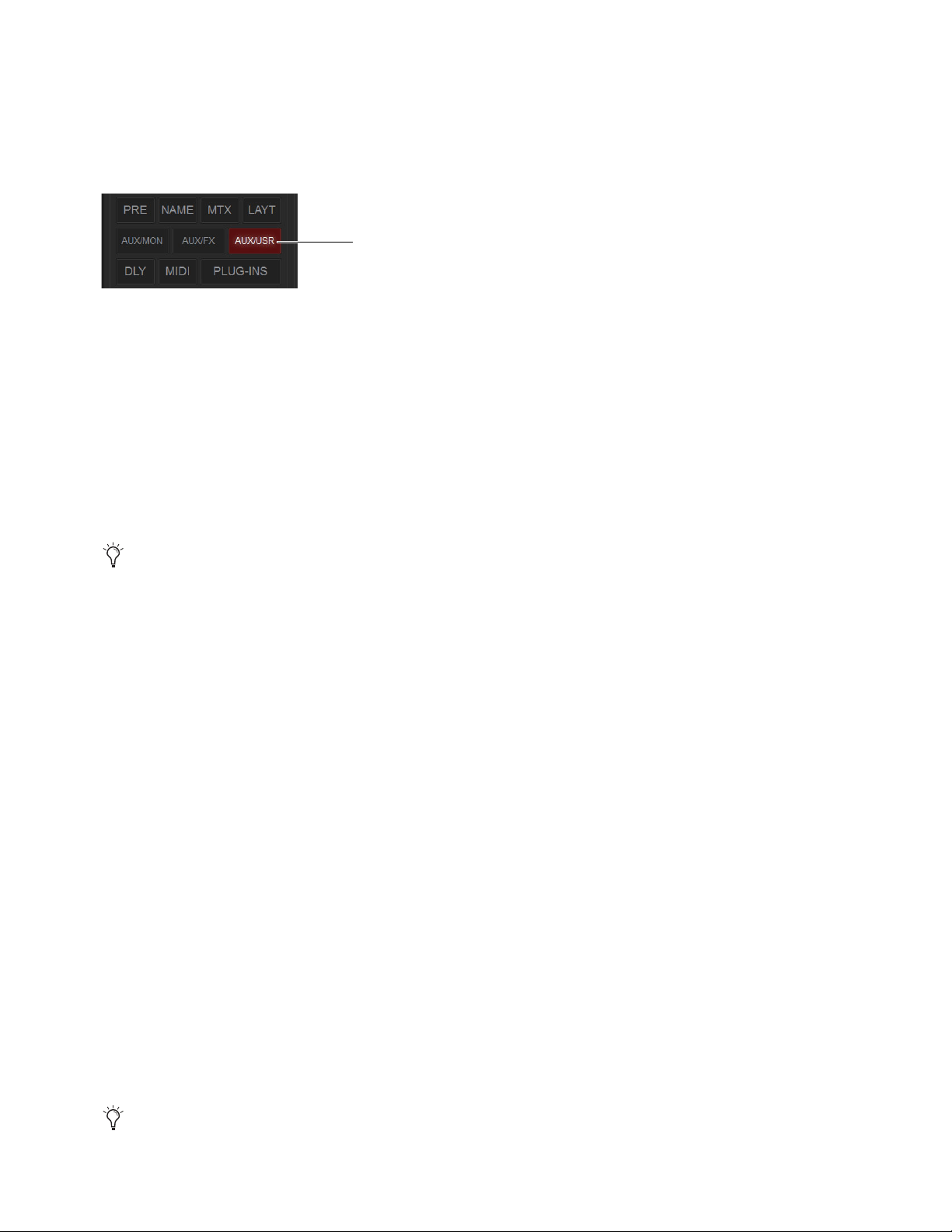
Snapshots 248
Using the User Aux Scope Grid
To enable User Aux Scope settings:
1 Go to the Snapshots page.
2 On the Main tab, enable the AUX/USR button in the Scope section.
When the AUX/USR button is enabled:
• The matrix in the User Aux Scope tab becomes active.
• Settings in the User Aux Scope tab are recalled with the current snapshot(s), as long as they are not Recall Safed.
When the AUX/USR button is not enabled the User Aux tab remains available but the matrix is taken offline and is grayed out,
indicating User Aux Scope settings will not be recalled with the current snapshot(s).
Aux Mon, Aux FX, and Aux User
When the AUX/USR Data Type Scope button is enabled in the Main tab of the Snapshots page, the AUXMON and AUXFX Data
Type Scope buttons remain available and control scope for Auxes classified as Mon or FX in the Options > Snapshots screen. En-
abling
AUXMON or AUXFX scopes the corresponding Auxes; by enabling AUX/USR you can add (or remove) individual Auxes.
To access the User Aux Scope grid:
1 Go to the Snapshots page and make sure the AUX/USR Data Type Scope button is enabled.
2 Select the User Aux Scope tab. Select a Channel tab to display the desired Input channels.
To scope individual Auxes on specific Input channels:
1 Make sure the desired Input channels are scoped (fader strips are red) in the Snapshot Main tab.
2 In the User Aux tab, select in the grid at the intersection of the appropriate Aux (column) and channel (row). A dot appears, in-
dicating that the corresponding Aux on that channel is scoped.
To scope multiple Auxes or channels at a time:
Touch and drag in a column, across a row, or at an angle.
To scope an Aux across all currently displayed channels:
Select the Aux grid icon at the top of the appropriate column until the triangle is white.
To scope all Auxes for a particular channel:
Select the Channel grid icon next to the Channel Name in the appropriate row until the triangle is white.
To toggle the status of an entire Aux column or channel row:
Select the appropriate Aux or Channel grid icon repeatedly until it displays the desired status. For more information, see
5–UserAuxScopeMatrix.
To scope all Auxes across all channels and clear any current settings:
Select the triangular icon at the upper left of the matrix (at the top of the ALL column).
AUX/USR button enabled in the Scope section of the Snapshots Main tab
The AUXMON and AUXFX scope buttons do not affect and are not affected by the AUX/USR button. The User Aux matrix does
not indicate scope status of AUXMON or AUXFX.
You can undo or redo the last action taken in the matrix. Selecting a different snapshot clears the Undo.
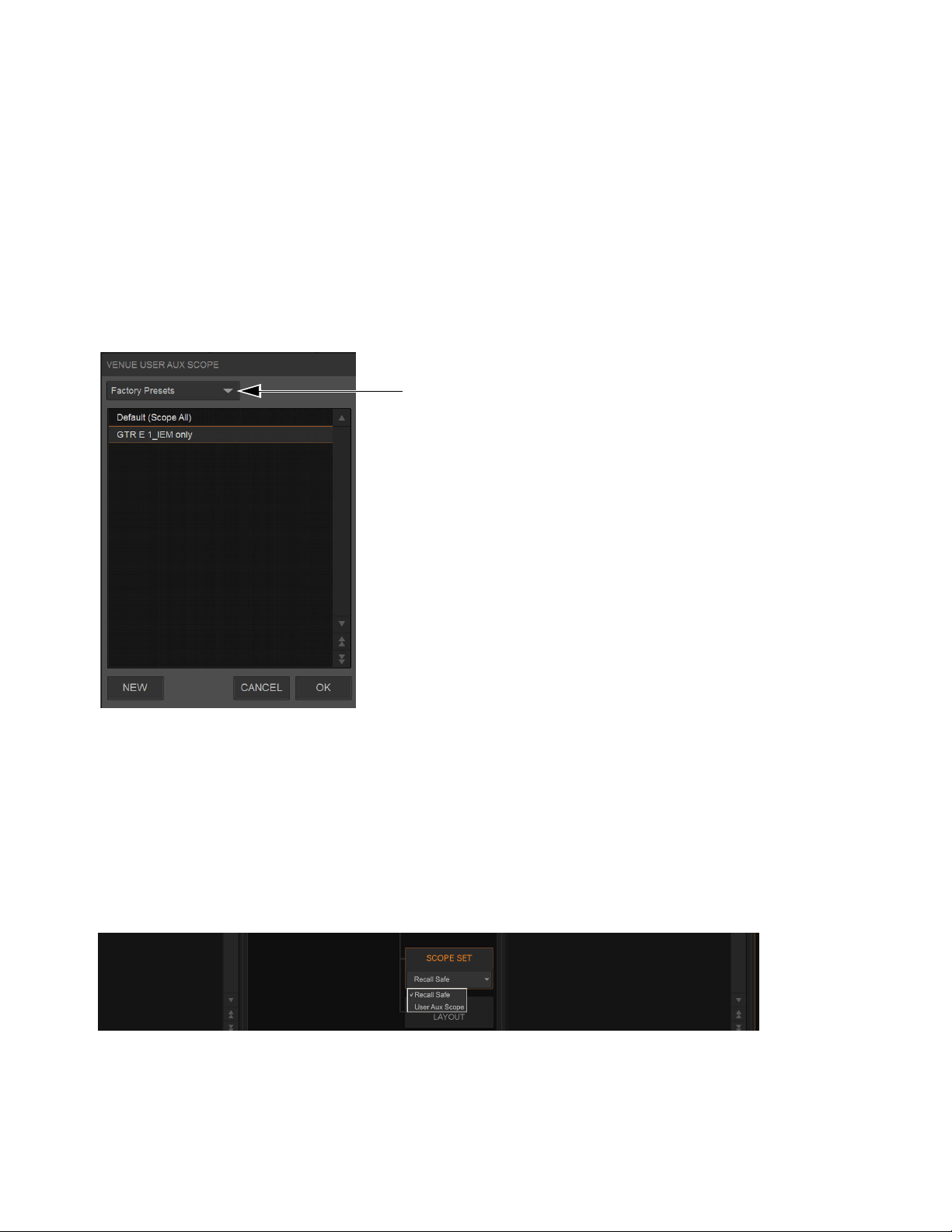
Snapshots 249
Using Aux User Presets
The configuration of the Aux User tab can be stored as a User Aux Scope settings file. User Aux Scope settings (presets) can be
previewed, recalled and transferred just like plug-in, EQ and dynamics settings.
To store the current User Aux Scope settings as a preset:
1 Configure the User Aux Scope tab as desired.
2 Select the Presets icon (the folder icon located above and to the right of the matrix).
3 Select New.
To preview and recall a saved preset:
1 From the User Aux Scope tab, select the Presets icon to display the User Aux Scope Presets window.
2 If necessary, choose the appropriate folder by selecting it from the Folder selector.
3 Do any of the following:
• To preview an existing preset, select its name in the window.
• To load the currently selected preset, press Enter or press
OK in the window title bar.
• To cancel without changing User Aux Scope settings, select Cancel.
Transferring User Aux Scope Presets
You can transfer User Aux Scope presets from the Filing page. To access User Aux Scope presets, touch-and-hold (right-click)
Scope Sets and choose User Aux Scope from the pop-up menu.
User Aux Scope presets Folder selector
Selecting Recall Safe or User Aux Scope

Snapshots 250
User Aux Scope Displays and Controls
The User Aux Scope tab provides the following displays and controls.
1 – Snapshot List
The Snapshot list and its primary functions (such as Previous and Next) remain visible and available from the User Aux Scope tab.
2 – Channel Tabs
Along the left side of the matrix are the Channel tabs, which select different ranges of Input channels listed in the matrix.
3 – Undo
The Undo function lets you undo the last action applied to the User Aux Scope matrix.
4 – User Aux Scope Presets
See Channel Safe.
Primary displays and controls in the User Aux Scope tab
Targeting (selecting) a different snapshot clears the User Aux Undo function.
1
2
3 4
5
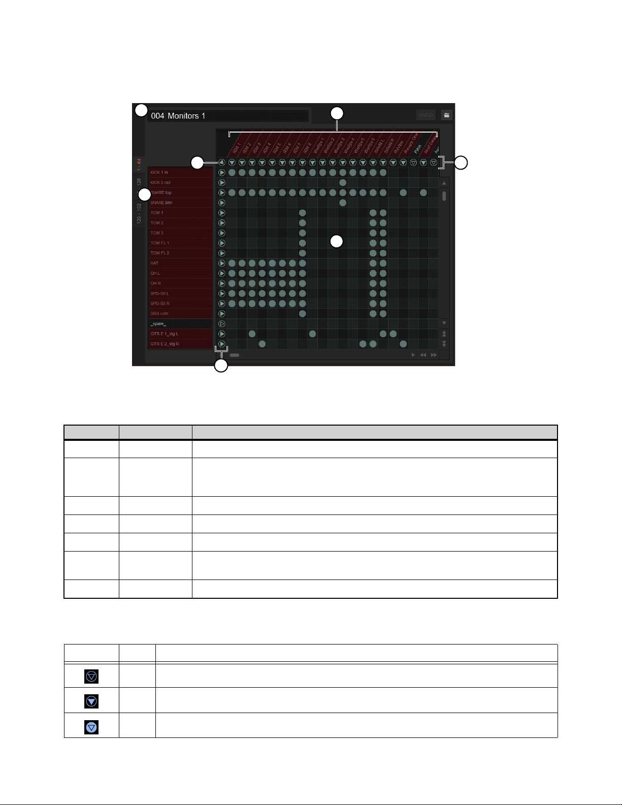
Snapshots 251
5–UserAuxScopeMatrix
The User Aux Scope matrix is a scrollable grid in which you can scope individual Auxes and Input channels. You can undo and
redo matrix operations.
The following table describes the elements of the User Aux Scope matrix shown in the figure above.
Matrix Icons
The display state of the Aux and Channel grid icons indicate scope status for that column or row as follows:
User Aux Scope matrix
Legend Item Description
1 Snapshot Displays the name of the currently targeted snapshot
2 Channels
Tabs select ranges of Input channels shown in rows in the list. Red indicates scoped channels (for a
channel to be scoped and red it must be scoped in the Snapshots Main tab). Double-clicking an Input
Channel name lets you rename it.
3 Channel icons Toggles scope of all Auxes on the corresponding channel; indicates scope status for that row
4 Auxes All available Auxes are listed across the top of the matrix. Red indicates scoped Auxes
5 Aux icons Toggles scope of the corresponding Aux on all channels; indicates scope status for that column
6 “All”
This single icon (above all Channel icons and to the left of all Aux icons) toggles scope on/off for all
channels and Auxes
7 Grid Matrix of channels and Auxes. A lit circle indicates that Aux is scoped on that channel
Icon Name Description
None A dark Aux or Channel grid icon indicates that no items in that column or row are scoped.
Some A lit triangle inside an unlit circle indicates that at least one item in that column or row is scoped.
All A lit (white) triangle and circle indicates that all items in that column or row are scoped.
6
4
2
1
7
3
5
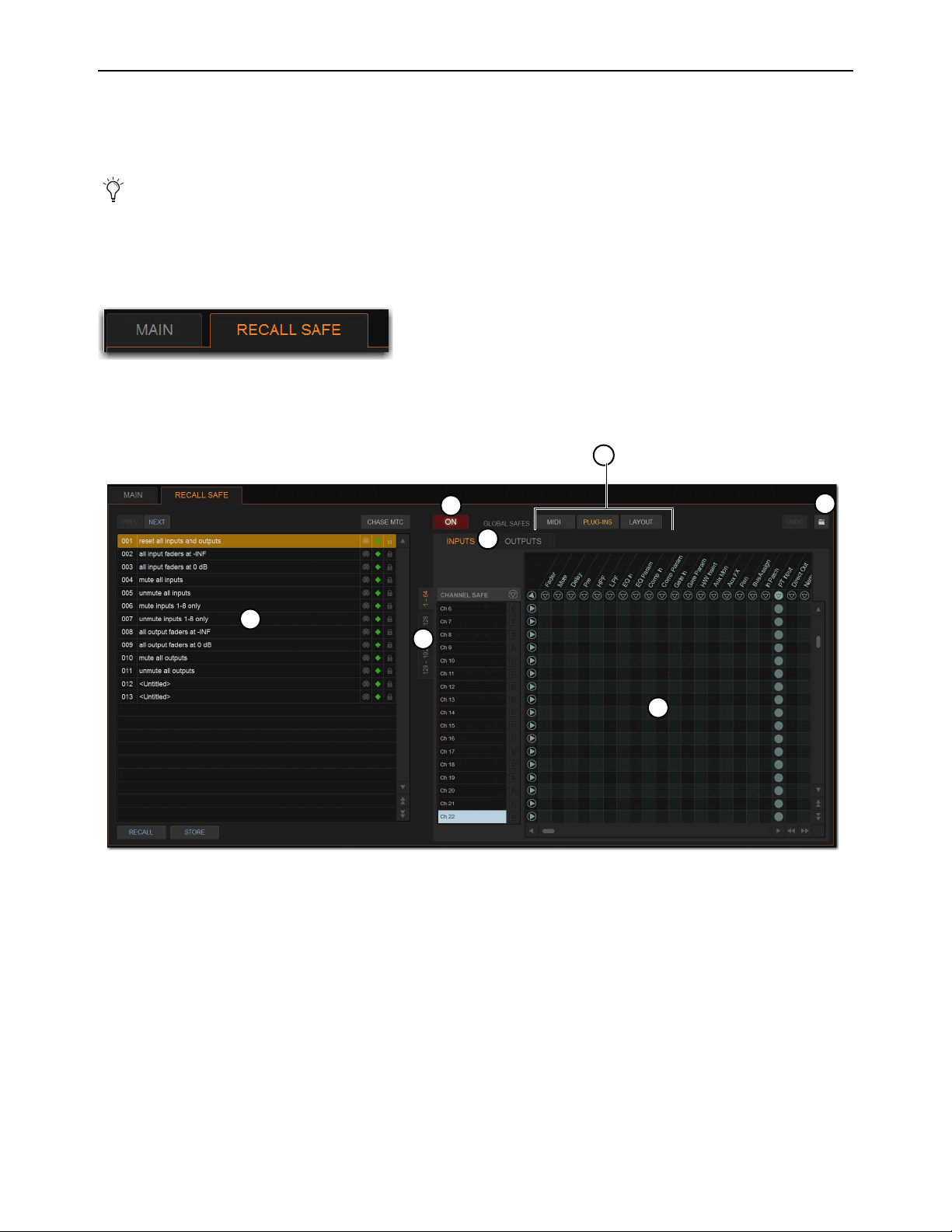
Snapshots 252
Recall Safe
Recall Safe lets you select which parameters on which channels you want to be “safed” from snapshots. Recall Safe is global to all
snapshots, can be turned on or off quickly, and provides preset capabilities in the form of Scope Sets. Scope Sets can be loaded and
saved just like Presets for built-in EQ, dynamics, and plug-in settings. Current Recall Safe settings are stored with the Show file.
To access Recall Safes:
1 On the external screen, go to the Snapshots page and select the Recall Safe tab. The Recall Safe tab is red when Recall Safe is
on and in effect, and gray when Recall Safe is off or when nothing is safed.
Recall Safe Displays and Controls
1 – On
The master On button toggles the entire Recall Safe feature on or off globally. When lit (blue), Recall Safe is active. When dark,
Recall Safe is suspended.
2 – Snapshot List, Recall and Store
The Snapshot list and its Recall and Store functions remain visible and available from the Recall Safe tab at all times.
3 – Channel and Channel Type Tabs
The Inputs and Outputs tabs at the top of the parameter matrix selects the channel type whose safe status you want to view or edit.
Along the left side of the parameter matrix are the Channel Type tabs, which change depending on whether you are viewing Input
or Output tabs.
Individual channels can be safed from all effects of snapshot recall using channel Automations Safe. See
Managing Snap-
shots.
Indication of active Recall Safe from the main Snapshots page
Displays and controls in the Recall Safe tab
1
2
3
4
6
5
3
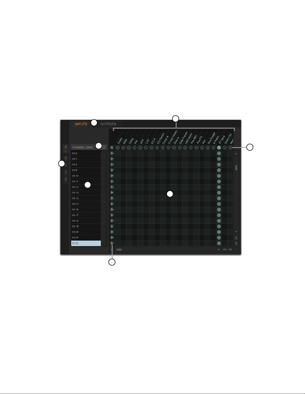
Snapshots 253
4 – Global Safe for MIDI Output, Plug-Ins, and Media
These checkboxes let you globally suspend recall of MIDI output, plug-in changes and/or Media page Transport commands. They
are considered separate from the parameter matrix and do not follow the Recall Safe master On (or Off) status.
5 – Scope Sets
Scope Sets are presets for the Recall Safe tab that can be stored and loaded, just like plug-in, EQ and dynamics presets. Scope sets
can be used as a template when creating new Shows, or used to change Recall Safe settings during a performance. Like other presets
and settings files, Scope Sets can be transferred from the Filing page, making it easy to maintain and transfer Recall Safe config-
urations. For more information, see Using Scope Sets.
6 – Parameter Matrix
The parameter matrix is a scrollable grid in which you can safe parameters and channels. You can undo and redo parameter matrix
operations.
Parameters are represented in the columns of the parameter matrix; channels are listed along the left side in rows.
Selecting in the grid enables safe status for that parameter on that channel. Parameter and Channel grid icons provide shortcuts to
quickly “safe all” parameters, and to safe entire channels. Selecting these icons lets you quickly toggle recall safe status for entire
columns and rows. You can also use the master grid icon located in the upper left most corner to toggle the entire grid.
Parameter matrix for Recall Safe
1 – Channels
2 – Channel Type Tabs
3 – Channel Icons
4 – Parameters
5 – Parameter Matrix Icons
6 – Channel Safe Button
7 – Grid
2
6
4
5
3
2
1
7

Snapshots 254
Parameter Matrix Icons
The display state of the Parameter and Channel grid icons indicate safe status for that column or row as follows:
None
A dark Parameter or Channel grid icon indicates that no items in that column or row are safe enabled.
Some
A dark triangle inside a lit blue circle indicates that at least one item in that column or row is safe enabled.
All
A lit (white) triangle indicates that all items in that column or row are safe enabled.
Channel Safe Controls
The CHANNEL SAFE column acts as a global “all channel” setting or override, mirroring the Channel Safe switches and buttons
(when in Channel Safe Switches act as Automation Safes mode).
Controls in the CHANNEL SAFE column are not part of the parameter matrix; they function in addition to the parameter matrix.
As a result, you do not need to enable any CHANNEL SAFE settings to use the Recall Safe parameter matrix.
Display states for grid icons in Recall Safe
For more information, see
Managing Snapshots.
None Some All
Grid master icon
Channel Safe
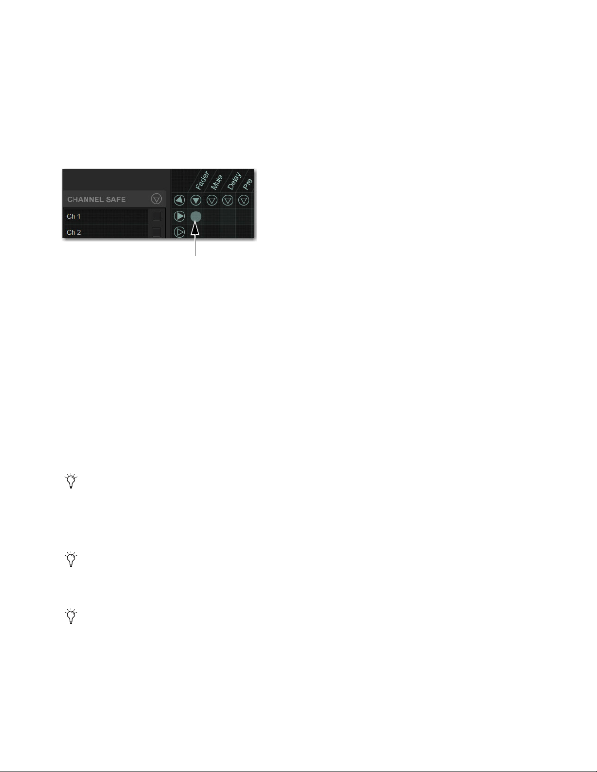
Snapshots 255
Using Recall Safe
To access Recall Safe:
1 Go to the Snapshots page and select the Recall Safe tab.
2 Select a Channel Type tab to display the desired channels.
To safe individual parameters on specific channels:
Select in the grid at the intersection of the appropriate parameter (column) and channel (row). A blue dot appears, indicating a
parameter is safed.
To safe multiple parameters or channels at a time:
Touch and drag in a column, across a row, or at an angle.
To safe a parameter across all currently displayed channel types:
Select the Parameter grid icon at the top of the appropriate column until the triangle is white.
To safe all parameters for a particular channel:
Select the Channel grid icon in the ALL column for that channel (row).
To toggle the status of a parameter column or channel row:
Select the appropriate Parameter or Channel grid icon repeatedly until it displays the desired status. For more information, see
6 – Parameter Matrix.
To safe all parameters across all channels and clear any current settings:
Select the triangular icon at the top of the ALL column.
Channel Safe
To automation safe an individual channel and retain all recall safe settings for that channel:
Select in the CHANNEL SAFE column for the desired channels.
To automation safe all parameters across all channels and retain all current recall safe settings:
Select the CHANNEL SAFE master icon at the top of the Channel Safe column.
Enabling recall safe for channel 1 fader
You can undo or redo the last action taken in the parameter matrix.
A channel (row) Channel Safe button does not need to be lit in order to Recall Safe individual parameters for that channel.
The Channel Safe column mirrors the channel automation Safe controls. For more information, see
Managing Snapshots.
Snapshots 256
MIDI
When engaged, this button prevents the MIDI data stored in the snapshot from being sent. This does not affect sending of Bank Se-
lect and Program Change commands with the Snapshots Send on Channel option (Options > Snapshots > MIDI).
To enable Recall Safe for MIDI Snapshot output:
Select the MIDI Snapshot Output Safe button, located above the parameter matrix.
Plug-Ins
When engaged, this button prevents plug-in control settings, in-circuit state, and routing from being recalled.
To enable Recall Safe for plug-ins:
Select the Plug-In Snapshot Safe button, located above the parameter matrix.
Media
When engaged, this button prevents USB 2-track record and playback transport commands for from being recalled.
To enable Recall Safe for USB 2-track Transport controls:
Select the Media Snapshot Safe button, located above the parameter matrix.
Matrix
Snapshots can store and recall all source assignments of each matrix mixer when the Matrix data types is scoped. In addition, all
User Input assignments are stored, letting you reconfigure Matrix mixers and User Input assignments on a per snapshot basis, if de-
sired.
The Recall Safe tab provides two data “Mix” data types that let you discretely “safe” source and/or user input assignments to pre-
vent them from being changed with a snapshot recall.
The following table describes what can be stored and recalled in each snapshot when the Matrix data types is scoped.
For more information, see
Adding MIDI Data to Snapshots.
For more information, see Adding Plug-In Data to Snapshots.
For more information, see Adding Tempo Data to Snapshots.
Table 4. Snapshot data types and parameters for Matrix mixers
Snapshot Data Type Included Parameters (for Each Scoped Channel Strip)
Matrix Mixer Input Sources, User Input Assignments (global to all Matrixes), and pickoffs; Mixer Input level,
Mixer Input on/off and Mixer Input Link
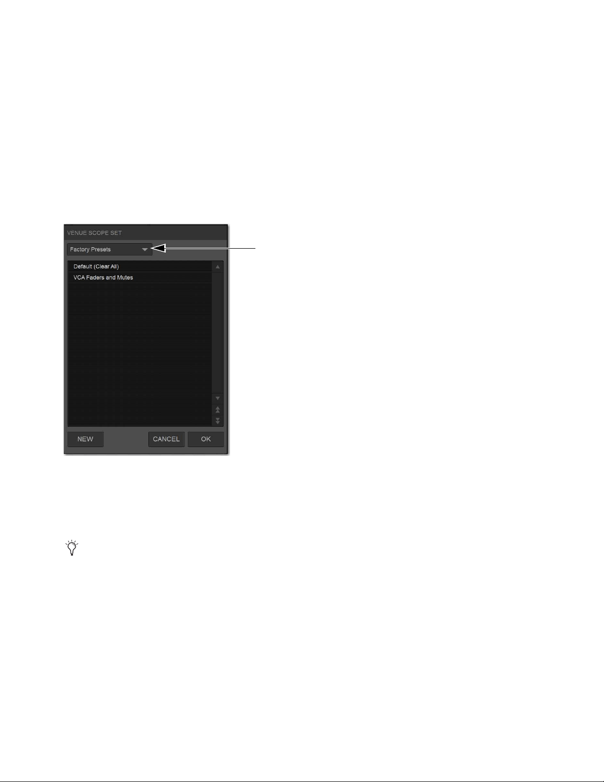
Snapshots 257
Using Scope Sets
The configuration of the Recall Safe tab can be stored as a Scope Set settings file. Scope Sets can be previewed, recalled and trans-
ferred just like plug-in, EQ and dynamics settings.
To store the current Recall Safe settings as a Scope Set:
1 Configure the Recall Safe tab as desired.
2 Select the Scope Sets icon (the folder icon located above and to the right of the parameter matrix).
3 Select New.
To preview and recall a saved Scope Set:
1 From the Recall Safe tab, select the Scope Set icon to display the Scope Set window.
2 If necessary, choose the appropriate Scope Sets folder by selecting it from the Folder selector.
3 Do any of the following:
• To preview an existing Scope Set, select its name in the Scope Sets window.
• To load the currently selected Scope Set, press Enter or press OK in the Scope Sets window title bar.
• To cancel without changing Recall Safe settings, select Cancel.
Scope Sets Folder selector
See
Filing for complete information on transferring system data.
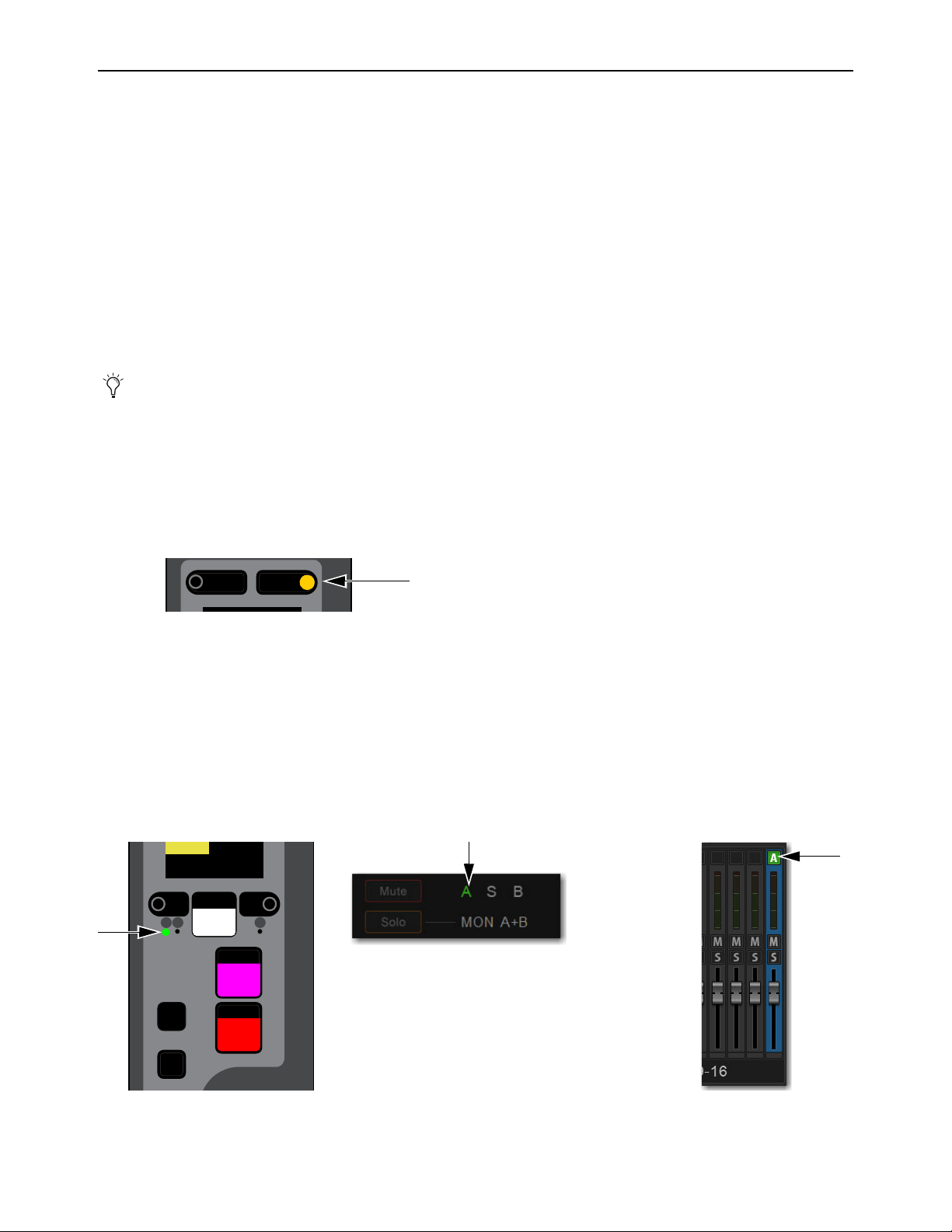
Snapshots 258
Automation Safing Channels
Automation Safing a channel lets you suspend the effect of snapshots on all parameters of the channel. You can Automation Safe
channels using the Channel Safe switches, the Channel Knob Module (CKM) in Channel Control mode, or the Channel Menu. To
Automation Safe channels using the Channel Safe switches, you must first enable Automation Safe mode.
Automation Safing Using the Channel Safe Switches/Button
The Channel Safe switch on the S6L control surface and the Channel Safe button on the external software screen toggle Automa-
tion Safe for that channel when Automation Safe mode is enabled. Automation Safe Mode is enabled globally for input and output
channels on the
Options > Interaction page of the external screen.
To enable Automation Safe for the Channel Safe switches:
1 On the external screen, go to the Options > Interaction page.
2 In the Channel Safe Switches section, under Inputs and Outputs, select Automation Safes as desired.
To Automation Safe channels using the Channel Safe switches:
1 Make sure you have enabled Automation Safe for the Channel Safe switches.
2 On the S6L control surface, do the following:
• Bank the desired channel to the faders.
• Press
Safe for the channel you want to Automation Safe.
3 On the external screen, do the following:
• Go to the Inputs or Outputs page, and navigate to the desired channel using the provided tabs and buttons.
• Select the Channel Safe switch for the desired channel, located at the top of each fader strip.
Automation Safe status for the channel is indicated as follows:
• On the control surface channel strip, the
A LED lights green.
• In the Input section of the MTS and CTM Channel view for the channel, A lights green.
• On the external screen the Safe button flashes green and shows the letter B (A appears if the switch is acting as an Automation
Safe, and S appears if it is acting as a Solo Safe).
You can create an event that lets you cycle through the various Channel Safe switch modes, as well as suspend or disable Au-
tomation Safe. See
Creating Events.
S6L Channel Safe switch engaged
Indications that a channel is Automation Safed on the channel strip (left) the MTS/CTM Channel view (center) and on the external screen
(right)
Menu Safe
Select
Solo
Y
X
Mute
AS B
CH 1
Ch 1
0.0 dB

Snapshots 259
Automation Safing Using the Channel Knob Module (CKM)
To Automation Safe a channel using the CKM:
1 Bank the desired channel to the faders.
2 Press the Select switch for the channel you want to Automation Safe so it lights, then press the INPUT Channel Control Func-
tion switch so it lights.
– or –
• Touch the channel’s Input touch zone on the associated Channel Touch Module (CTM).
Input parameters are assigned to the associated CKM.
3 Locate the Automation Safe encoder, indicated by Auto Sf on the encoder display, and press the encoder.
The encoder In switch lights green, and the channel is Automation Safed.
CKM Channel Control Function Switches
Input touch zone on the CTM in Meters view (left) and in Channel view (right)
Automation Safe parameter on a CKM encoder
MIXMIXMIXPLUG-INSDYNAMICSEQINPUTCHANNEL
In
Sel
In
Sel
In
Sel
In
Sel
In
Sel
In
Sel
In
Sel
In
Sel
In
Sel
Auto Sf
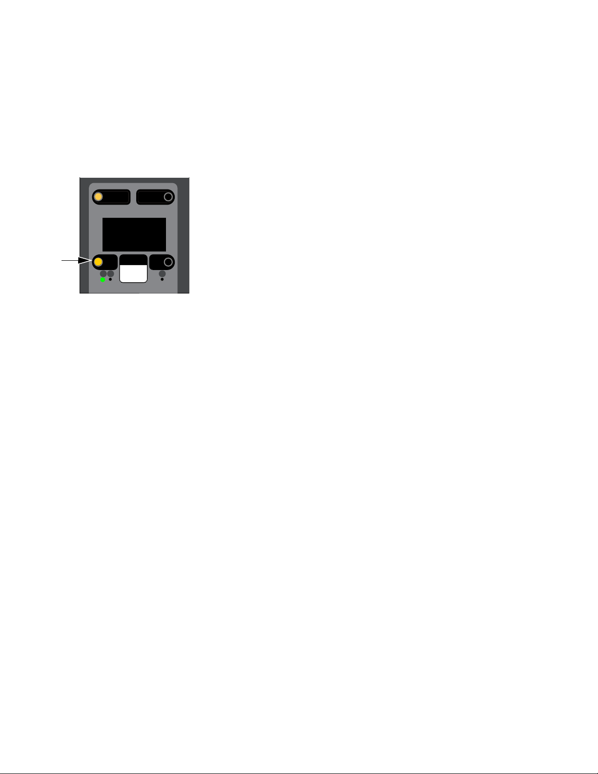
Snapshots 260
Automation Safing Using the Channel Menu
You can Automation Safe a channel using the Channel Menu when a different Safe mode (such as Bank and/or Solo Safe) is en-
abled for the Channel Safe switches.
To Automation Safe a channel using the Channel Menu:
1 Bank the desired channel to the faders.
2 Press the Menu switch for the channel you want to Automation Safe until Safe Mode appears in the channel display. The Safe
modes enabled by the Left and Right Channel Menu switches are shown below Safe Mode.
3 Press the Left Channel Menu Switch so it lights to Automation Safe the channel. The A LED lights green.
Right Channel Menu switch engaged
Menu Safe
Mute
AS B
Ch 1:Stage1-01
Source
Auto/Bank
Safe Mode

Snapshots 261
Snapshot Data Types and Parameters
Table 5. Snapshot data types and parameters included in each data type
Snapshot Data Type Included Parameters (for Each Scoped Channel Strip)
Fader Main volume level
Mute Mute state for explicitly muted channels, and channels muted via VCA mute (Mute Group state is not snap-
shottable)
EQ EQ type selection (analog/digital); EQ in-circuit state;
Band gain, freq, Q, bell/shelf selection (digital only), band on/off
Dyn Compressor/Limiter in-circuit state; threshold, ratio, attack, release, knee, makeup gain
Expander/Gate in-circuit state; threshold, ratio, attack, release, hold time, range, side-chain input
Pan Channel pan or balance/width
Pan or balance/width for each Group bus returning back to L–R
Bus Group bus assignments, group bus mono/stereo-linked state (if mono groups) or dual-mono/true stereo
state (if stereo groups), L–R bus assignment and C/M bus assignments for input strips and groups
In Input routing for input channels.
Out Main out assignments; direct out assignments, level, in-circuit state, & tap-off point (excluding VCAs)
H/W Hardware Insert routing and in-circuit state (excluding VCAs)
VCA VCA membership
Pre Gain, pad, phase, phantom power, HPF corner frequency & in-circuit state
Name Name for each strip
MTX Mixer Input Sources, User Input Assignments, and pickoffs; Mixer Input level, Mixer Input on/off and Mixer
Input Link state
LAYT User Layout
Aux Mon On/off, pre/post selection, level, and pan/balance for each Aux bus classified as a Monitor Aux
Aux FX On/off, pre/post selection, level, and pan/balance for each Aux bus classified as an FX Aux
AUX USR On/off, pre/post selection, level, and pan/balance for each Aux bus enabled in the User Aux grid
Dly Channel delay time & in-circuit
MIDI All MIDI messages that were added to the associated MIDI list for that snapshot.
Plug-Ins Rack slot settings, in-circuit state, and I/O routing for each plug-in added to plug-ins list for that snapshot
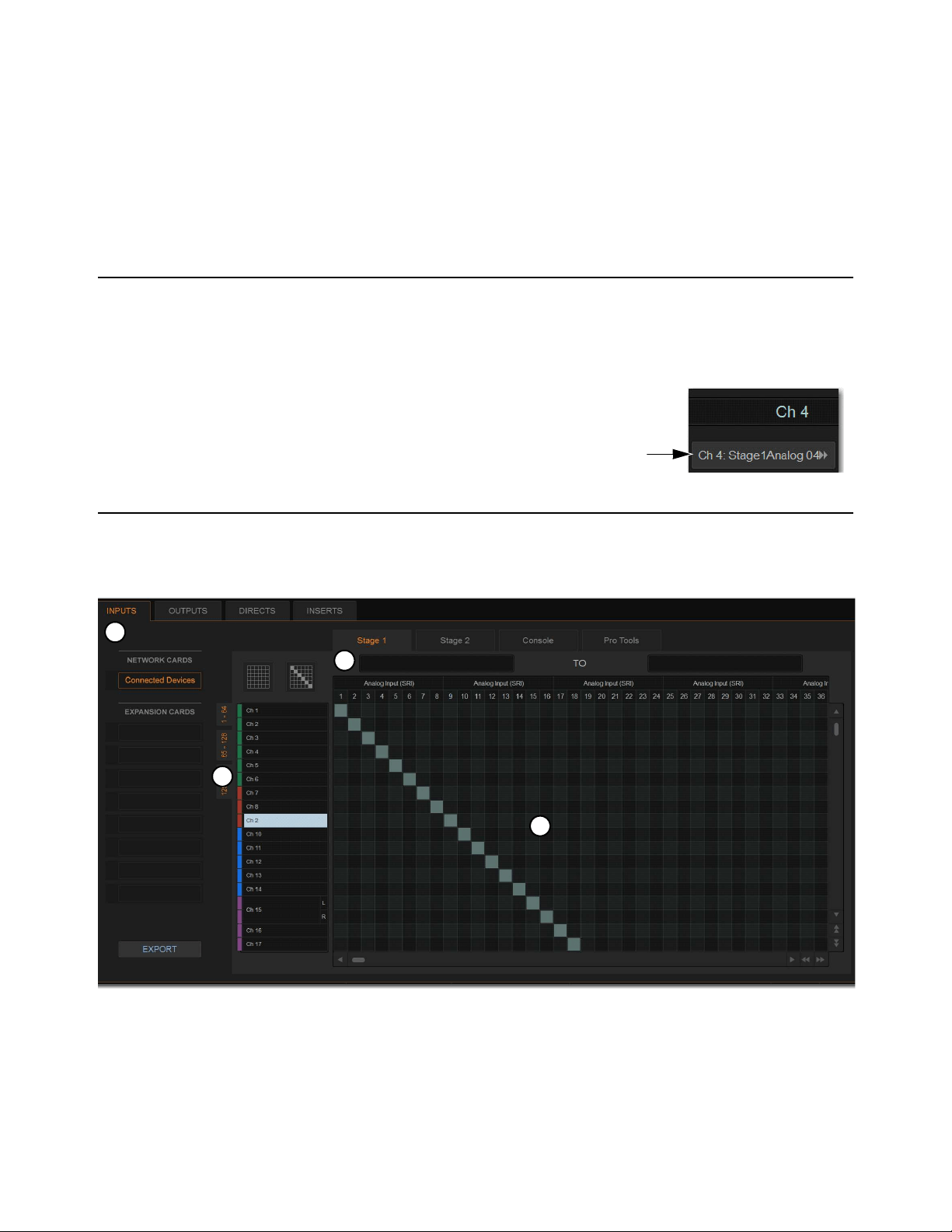
Patchbay 262
Patchbay
The Patchbay is used to assign Input and Output Channels, Direct Outputs, and Inserts to hardware inputs and outputs. The Patch-
bay also provides the ability to name input and output channels and to export your patchlist.
Accessing the Patchbay
To show the Patchbay screen:
Select the Patchbay button on the external screen.
To jump to the Patchbay from the Inputs and Outputs screens:
Select the channel routing indicator, right below the channel name display. The screen au-
tomatically jumps to the corresponding Patchbay screen (whether an input, output, or bus).
Overview of the Patchbay
The Patchbay screen lets you patch hardware I/O to input and output channels, and consists of the following tabs and controls:
Patchbay page (Inputs tab shown)
1 –
I/O Tabs
2 – Hardware Tabs
3 – Channel Type Tabs
4 – Patching Grid
3
4
2
1
Patchbay 263
I/O Tabs
Select these tabs to display and patch Inputs, Outputs, Directs (Direct Outputs), or Inserts. Other options in the Patchbay screen
change to reflect the currently selected I/O tab.
Hardware Tabs
Select these tabs to display the hardware inputs and outputs available for the current I/O and Channel Type. These tabs represent
the physical inputs and outputs of the system, as follows:
Available hardware inputs and outputs are based on channel type selection, system configuration and hardware device status. See
Unavailable I/O.
Channel Type Tabs
Select these tabs to select and display specific types of channels, as available for the currently selected I/O. The following table
shows the available Channel Types for the current I/O.
Network and Expansion Cards
Select items under Network Cards or Expansion Cards to select and display channels for the corresponding IO devices.
Network Cards (Connected Devices)
Displays I/O available on connected Stage 64s (such as SRI, SRO, DSI, DSO, or DNT-192
Dante cards).
Expansion Cards
Displays I/O available on E6L option cards, if any, such as MADI-192 MADI Option cards.
Patching Grid
The patching grid shows hardware I/O across the top, and system channels (with colors) down the left side. The available channel
tabs and choices are determined by the currently selected I/O tab and Channel type(s). The grid squares represent patch points be-
tween hardware I/O and VENUE mixing channels.
Navigating the Patching Grid
To scroll through the channel list (vertically):
Select a channel name at the left of the patching grid, then press the Up or Down Arrow keys on the keyboard.
To scroll through the hardware I/O list (horizontally):
Select a hardware I/O channel at the top of the patching grid, then press the Left or Right Arrow keys on the keyboard.
The Inserts tab lets you patch hardware inserts on input and output channels. See
Hardware Inserts for more information.
Hardware Tabs Hardware Inputs Hardware Outputs
Stage (1–6) Stage I/O unit analog and digital inputs Stage I/O unit analog and digital outputs
Console S6L control surface analog and digital inputs, and the
built-in oscillator.
S6L control surface analog and digital outputs
Local (1–2) Local 16 analog and digital inputs Local 16 analog and digital outputs
Pro Tools Assignable Ethernet AVB Inputs from Pro Tools (see
S6L Live Recording Guide.pdf for more information).
Assignable Ethernet AVB outputs to Pro Tools (see S6L
Live Recording Guide.pdf for more information).
I/O Tab Channel Types available
Inputs Input channels
Outputs Mains, MTX (Matrixes), Auxes, Groups
Directs Input and Output Channels
Inserts Input and output channels.

Patchbay 264
To scroll the patching grid, do one of the following:
Select the up/down or left/right patching grid scroll arrows to move square by square.
Select the up or down patching grid double arrows to move screen by screen.
Touch and hold in the patching grid and drag in any direction.
Navigating to Channel Types
The Patchbay uses multiple tabs to access different hardware I/O and channel types in the patching grid. For example, the Outputs
tab provides sub-tabs of output channel types for you to patch these different outputs independently.
Examples
To show output channels:
Go to the Patchbay page and select the Outputs tab.
To show a specific type of output in the patching grid:
In the Patchbay page, select the MAINS, MTX (Matrix), GRP, or AUX tabs. Press and hold Shift, then select multiple tabs to
show multiple types at once.
To show Stage 64 I/O, select Connected Devices (below NETWORK CARDS). To show E6L I/O (such as MADI-192 MADI
Option cards, if any), select MADI-192 below EXPANSION CARDS.
To navigate to a different hardware source:
Select the appropriate hardware tab across the top of the patching grid.
Visual Indicators and Displays
The Patchbay uses the following visual display conventions in all its tabs and pages.
Available I/O
When I/O is available for patching, the patching grid for the corresponding I/O lights.
Patched I/O
When a hardware connection is patched, its connection is dimmed in all Patchbay screens. This lets you see which hardware con-
nections are in use without having to switch back and forth between Patchbay screens. You can also use the dimmed column num-
ber indicator to jump to the Patchbay page for the existing assignment (for more information, see Shortcut for Locating Assign-
ments).
Unavailable I/O
The Patchbay displays hardware tabs for all possible configurations. For example, if your current configuration includes two Stage
64 I/O racks, three Stage tabs still appear in the Patchbay. Unavailable I/O for unconnected Stage 64 I/O racks and either unavail-
able or reserved Pro Tools I/O is indicated in the patching grid as follows:
Stage I/O
Appears grayed out in the Patchbay under its corresponding hardware tab, and is italicized in all routing pop-up lists.
Pro Tools I/O
When a Pro Tools computer is connected to the S6L control surface, system input channels with Stage inputs as-
signed to them are highlighted in purple under the Pro Tools hardware tabs in the Patchbay. This indicates that the Pro Tools I/O
channels are reserved for use as direct digital splits to Pro Tools (outputs) or Virtual Soundcheck channels (inputs).
Shared I/O
The Patchbay indicates input and output ownership of Stage 64s and Stage 32s using colored text (see
IO Sharing Example).
When a Pro Tools computer is not connected, all Pro Tools I/O is grayed out and unavailable in the Patchbay.
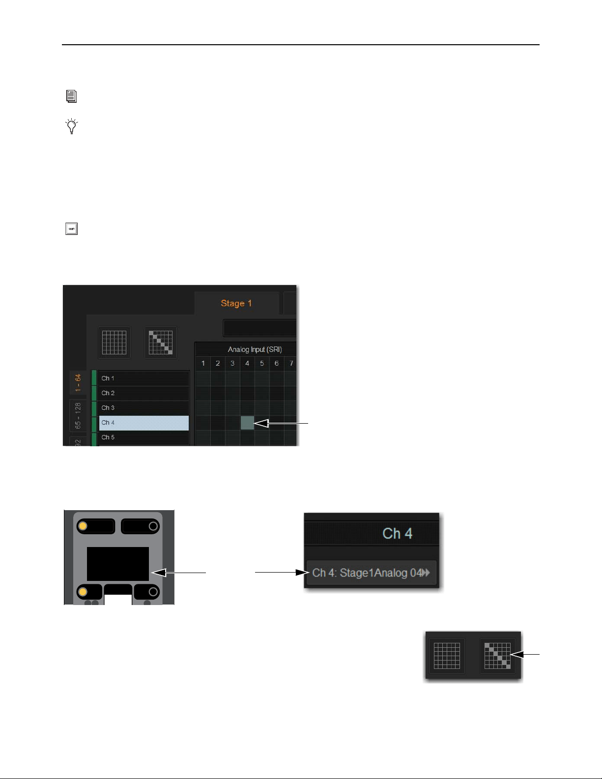
Patchbay 265
Patching Input Sources to Input Channels
You can patch inputs sources to input channels using the Patchbay on the external VENUE software screen.
To patch a single input source to an input channel:
1 On the external screen select Patchbay.
2 Select the Inputs tab.
3 To the left of the patching grid, select the range of input channels yo want to access in the patching grid.
4 Along the top of the patching grid, select a hardware tab to display hardware input sources.
5 Touch in the row for the channel and in the column for the hardware source. Grid squares light when channels are patched.
Channel source information is shown on-screen under the channel name on the external screen Inputs page, and on the MTS and
CTM in Channel view. Channel source information is also shown on the control surface on the Channel Menu Source page in the
channel display.
To assign multiple channels in a single action, do either of the following:
Touch, hold, and drag vertically, horizontally, or at an angle to assign multiple patch points
in a single action.
Select the Default Assignment button, and then select Assign in the confirmation dialog to
assign all Stage inputs currently displayed in the channel grid to multiple consecutive input
channels.
Plug-in outputs can also be an input source. See
Routing Plug-Ins as Bus Processors (Effect Send/Return).
The S6L system comes pre-loaded with Demo show files, which offer preset system configurations for some of the most common
mixing scenarios, including pre-patched inputs. See Loading a Show for instructions on loading Show files.
Shift-touch any number of Channel Type and/or hardware tabs to select and display multiple tabs in the patching grid.
A lit grid square showing a hardware input source patched to an input channel
Channel Menu Source page (left) and Inputs page of the external screen (right)
Menu Safe
Mute
AS B
Ch 1:Stage1Analg1
Source
The Default Assignment button
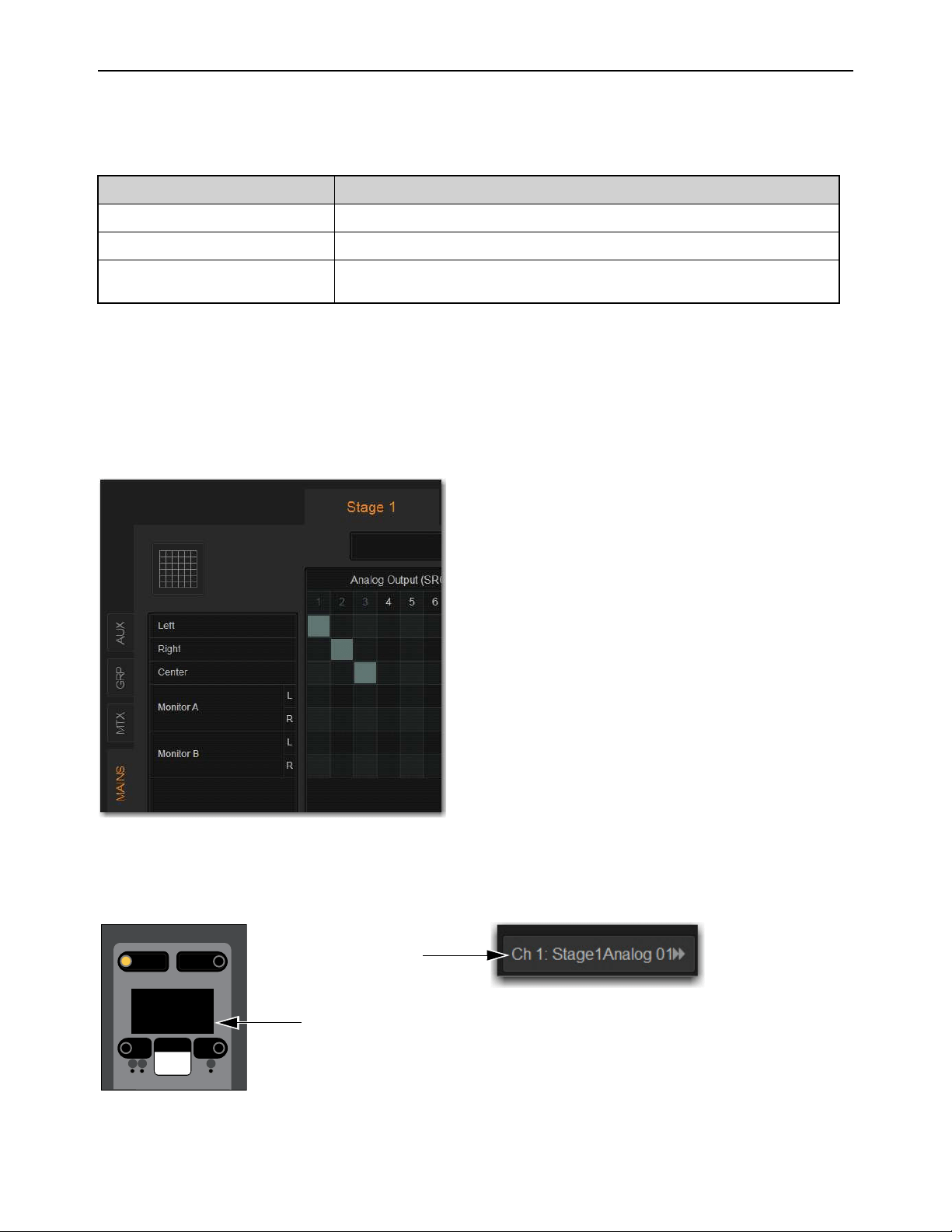
Patchbay 266
Patching Output Channels to Hardware Outputs
Mains, Auxes, Groups and Matrix Mixer outputs can be assigned to any hardware output on the system using the Patchbay. In the
Patchbay, each S6L system component has a corresponding hardware tab that displays the available hardware output destinations,
as follows:
To assign an output channel to a hardware output from the Patchbay:
1 Go to the Patchbay and select the Outputs tab.
2 To the left of the channel grid, select the Mains, Mtx (Matrix), Grp (Groups), or Aux tab to display those output channels in the
grid.
3 Along the top of the channel grid, select a hardware tab to display available hardware output destinations.
4 Touch in the row for the channel and in the column for the hardware destination. Grid squares light when channels are patched.
Channel destination information is shown on-screen under the channel name on the external screen Outputs page, and on the MTS
and CTM in Channel view. Channel destination information is also shown on the control surface on the Channel Menu Destination
page in the channel display.
Hardware Tabs Component Hardware Outputs
Stage 1–6 Stage I/O unit analog and digital outputs
Console S6L control surface analog and digital outputs
Pro Tools Assignable Ethernet AVB outputs to Pro Tools (see the S6L Live Recording Guide.pdf for
more information).
Mains patched to a Stage 64 hardware output
Channel Menu Source page (left) and Inputs page of the external screen (right)
Menu Safe
Mute
AS B
Left:Stage1Analog1
Destination
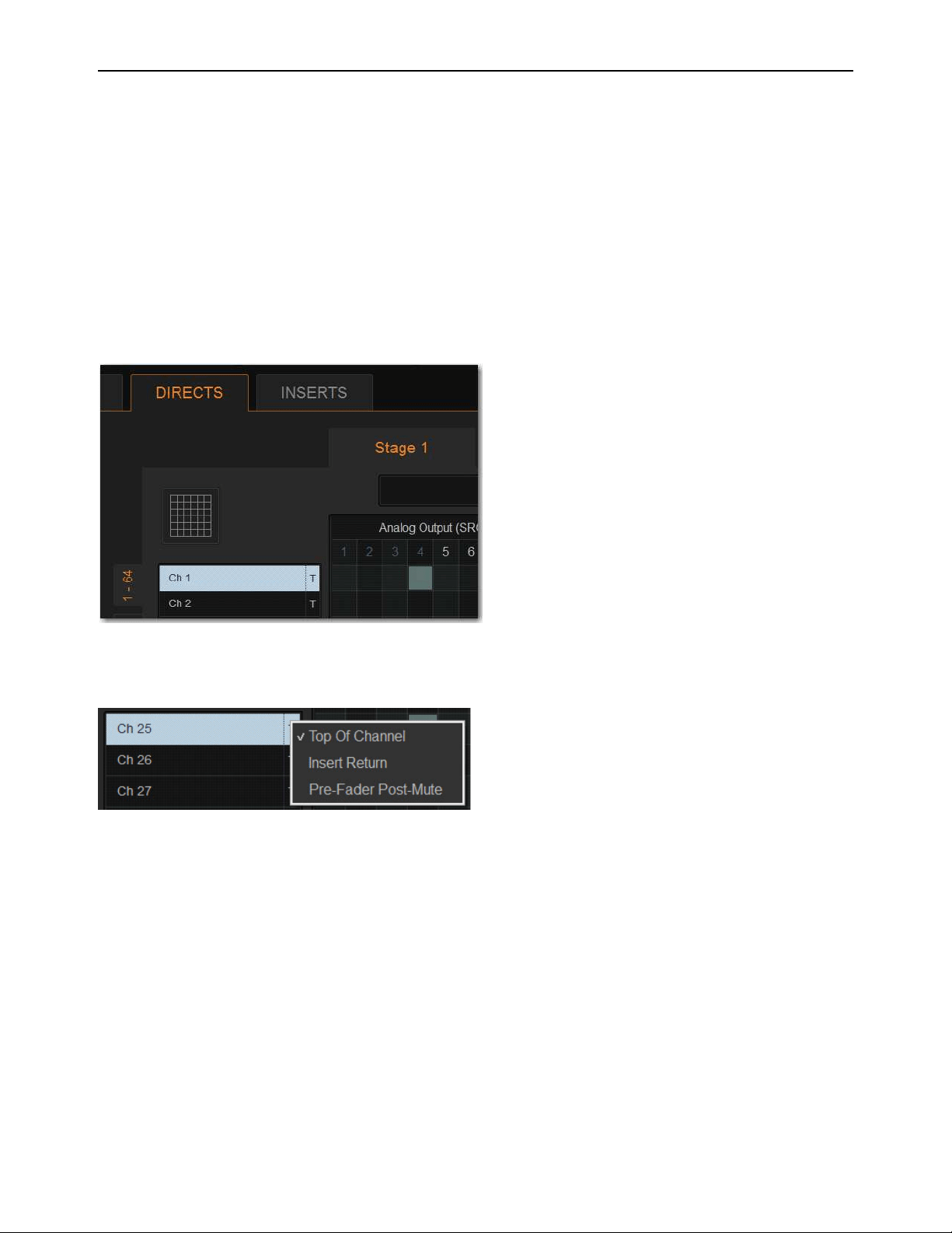
Patchbay 267
Patching Direct Outputs
Direct Outputs of input channels, Auxes, Groups, Matrix Mixer, and Mains outputs can be assigned to any hardware output or
Pro Tools output using the Patchbay Directs tab. Each hardware output destination may be fed by only one Direct Output signal
(multiple Direct Output signals cannot be routed to a single output). You can choose the pickoff point for each channel’s Direct
Out.
To assign a channel to a Direct Output:
1 Go to the Patchbay page and select the Directs tab.
2 To the left of the channel grid, select the Mains, Mtx (Matrix), Grp (Groups), or Aux tab to display those output channels in the
grid.
3 Along the top of the channel grid, select a hardware tab to display available hardware output destinations.
4 Touch in the row for the channel and in the column for the hardware destination. Grid squares light when channels are patched.
5 Select the pickoff point for the Direct Output by selecting the letter to the right of the channel and choosing from the pop-up
menu. See
Direct Output Pickoff Points.
Assigning a Direct Output in the Patchbay
Selecting a Direct Output pickoff point in the Patchbay
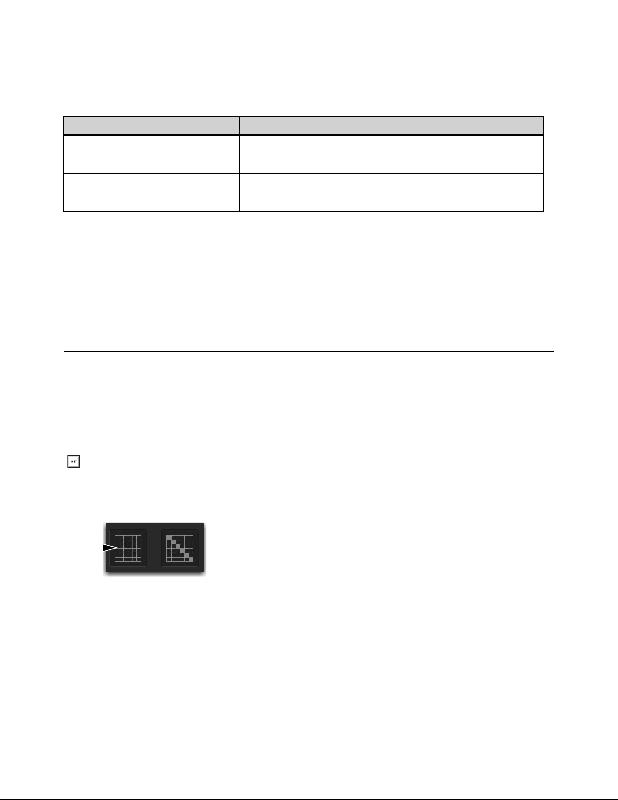
Patchbay 268
Direct Output Pickoff Points
The “pickoff point” is the point in the signal path where the audio signal is picked off the main signal and sent to the Direct Output.
The pickoff points for Direct Output signals are selected in the Directs tab of the Patchbay page. The following pickoff points are
available for each type of channel or bus:
Pickoff points for input channels are configured as pre-or post-fader globally.
Configuring Input Channel Pre-or Post-Fader Pickoff Points
Pickoff points for input channels are configured as pre-or post-fader globally.
To configure the Direct Output pickoff point for Inputs:
1 Go to the Options page and select the Pickoffs tab.
2 Under Input Channel Fader Pickoff Point, select Pre-Fader or Post-Fader.
Unpatching and Clearing Assignments
To unpatch a single channel in the Patchbay:
Touch a lit square in the patching grid corresponding the channel you want to unpatch
To clear Patchbay Assignments:
1 Select the appropriate I/O tab, Channel Type tab, and Hardware tab.
2 In the top left corner of the patching grid, select the Clear Assignments button, and select Clear in the ensuing dialog. All Patch-
bay assignments for the selected Patchbay pages are cleared.
3 Repeat for other types of I/O as necessary.
Pickoffs for Direct Outs
Channel Type Available Pickoff Points
Input-channels Top of channel
Insert return
Pre-Fader, or Post-Fader (configured globally in Options > Pickoffs)
Output channels Top of <bus>
Pre-Fader Post-Mute
Post-Fader
To clear all Input, Output, Direct, or Insert assignments, press and hold Shift, then select all Channel Type and Hardware tabs
to select all pages.
The Clear Assignment button
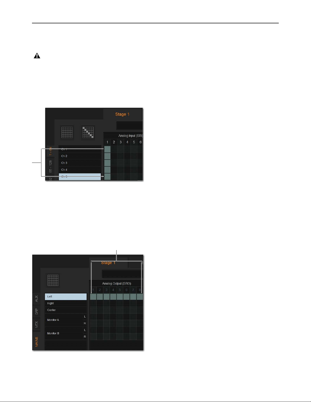
Patchbay 269
Multiple Input and Output Patching
A single hardware input source can be patched to multiple input channels in the Patchbay. An output bus can be patched to multiple
hardware outputs.
To assign a hardware input source to multiple input channels:
1 Go to the Patchbay page and select the Inputs tab.
2 Patch the input source for the first input channel.
3 Select additional grid squares in the same column to assign the source to additional channels so they are lit. The selected hard-
ware input is patched to each of the assigned input channels.
To patch an Output bus to multiple hardware outputs:
1 Go the appropriate Patchbay page and select the Output tab.
2 Patch assign the desired output channel to the first hardware output.
3 Select additional grid squares in the same row to assign the same output channel to additional hardware outputs. The selected
output channel is assigned to all the assigned hardware outputs. An asterisk (*) appears at the end of the displayed destination
to indicate the multiple routing.
Multiple input sources cannot be assigned to a single input channel.
A hardware input routed to multiple input channels
Mains Left patched to multiple hardware outputs

Patchbay 270
Warning When Stealing Inputs or Outputs in the Patchbay
The Patchbay indicates hardware outputs that are already in use by dimming the column number for that physical output. In addi-
tion, a dialog is shown if the patch will steal a hardware input or output that is already in use, asking you to confirm or cancel the
reassignment.
To confirm a reassignment, do one of the following:
Select Assign when prompted to confirm the reassignment.
– or –
Select again on the same patch point.
To cancel a reassignment, do either of the following:
Select Cancel to leave the patchpoint unchanged.
Select any other point in the grid (the Patchbay grid remains active, even when the Confirm Assignment dialog is open
on-screen).
Shortcut for Locating Assignments
Before reassigning in the Patchbay, you may want to double-check the existing assignment to the desired hardware output. This can
be done quickly from within the Patchbay.
To identify the bus or channels currently assigned to a hardware output:
Select any dimmed (already assigned) column number at the top of the Patchbay. The Outputs page containing the assignment
is automatically revealed in the patching grid.
Naming Channels from the Patchbay
Channel names can be changed from the Patchbay. Channel names can be up to 32 characters in length. When shown in the displays
on the S6L control surface, channel names are abbreviated to fit the displays.
To name or rename a channel from the Patchbay:
1 Double-tap the channel name at the top of the screen or in the column of the grid.
2 Type a new name and press Enter on the computer keyboard.
If you repatch a hardware input to a different channel, Input gain, pad and phantom power move with the hardware input, re-
placing those settings on the destination channel. This occurs when repatching manually (in the Patchbay) or via a snapshot.
Warning when reassigning an output that is already in use
To suppress the reassignment warning dialog, hold Default (on the S6L control surface) or Alt (keyboard) while selecting in the
patch grid to change the assignment.
When naming channels from the columns of the grid, press Tab on the keyboard to go to the next channel; press and hold the
Shift key and Tab to go to the previous channel.

Patchbay 271
Type Text Search
Type Text search lets you use the keyboard for fast navigation to a channel. You can enter the first characters of a channel name
or the absolute channel number to target that channel.
To search for and select a channel:
1 Type the first few letters, full name, or channel number of the channel. For example, type “s” to go to the first channel beginning
with the letter s (such as Snare).
2 Press the Tab key to cycle through and select any other channels beginning with that letter (such as Snare Top, Snare Bottom, or
Strings).
Patch List Export
The Patchbay Export generates a patch list in an easily readable format.
To export Patchbay information:
1 Insert a USB storage device into any USB port on the S6L control surface.
2 Go to the Patchbay page and select the Export button.
3 Do any of the following:
• If you have more than one USB device connected, make sure the correct USB one is selected. If it is not, select Next Disk to
cycle through until the correct one is selected.
•Select
Save to export info to the selected USB device (or select Cancel to dismiss the dialog without exporting).
4 Select OK to confirm the export procedure. You can now remove the USB device and transfer the exported file to a personal
computer for printing, formatting, and distribution.
Contents of Exported Patchbay Information
Exported Patchbay information is saved as an HTML file, and the file name includes the date and time of the export. Contents in-
clude the following:
VENUE Patch List
Show
Name, file path, date and time of Show file.
Input and Output Patching (Stage, Console, and Pro Tools)
Stage I/O
Hardware input and output numbers and the channel numbers or names are shown for each Stage I/O unit.
Console I/O
Hardware input/output types and numbers, and channel patch are shown.
Local I/O
Hardware input/output types and numbers, and channel patch are shown for each Local 16.
Pro Tools I/O
Pro Tools input and output channel numbers and channel patch are shown.
• Unavailable channels are labeled N/A.
• Direct outs are identified uniquely.
Avoid giving channels names that begin with numbers different from the absolute channel number. When you type a number,
VENUE navigates to absolute channel numbers regardless of the channel name.
Patchbay Export Information button
When exporting a Patch list from the Standalone software, the generated HTML file is automatically opened using your default
Internet browser (such as Internet Explorer, Mozilla Firefox or other).

Plug-Ins 272
Plug-Ins
This chapter explains how to configure plug-ins before a performance, and how to use plug-ins during a performance. Plug-Ins can
be inserted on all channels and bus outputs, or used as bus processors for effects such as reverb and delay.
When a
WSG-HD Waves SoundGrid Option Card and Waves Plug-Ins are installed in an E6L engine, Waves SoundGrid
plug-ins can be integrated directly into your VENUE mixes just like other VENUE plug-ins.
Plug-Ins Quick Start
Before a performance, enable Config mode and do any of the following:
• Install plug-ins (see
Installing and Authorizing Plug-Ins).
• Assign plug-ins to racks and rack slots (see
Plug-In Racks).
• Assign plug-in input and output routing, including sidechain routing (see
Routing Plug-Ins).
• View and adjust plug-ins from the S6L control surface or on-screen (see
Adjusting Plug-Ins on the External Screen).
• Save and load plug-in settings as Presets, or with snapshots (see
Plug-In Presets and Snapshots).
During a performance, do all of the following:
• Enable Show mode to “safe” (lock out) plug-in rack assignments and other plug-in rack operations that could interrupt a perfor-
mance.
• Patch channels and buses to available plug-ins, re-assign plug-in routing, or re-assign existing side-chain routing.
• Adjust plug-in parameters from Channel Control, Global Control, or on-screen.
• Save and load plug-in settings as Presets, or within snapshots.
Using Config and Show Modes for Plug-Ins
The current system mode status (Config or Show mode) determines which plug-in functions are available.
Config mode is required to install plug-ins, assign them to rack slots, and to establish side-chain routing. When in Show mode, any
operations that might interrupt audio throughput are locked out and unavailable.
S6L systems support 64-bit AAX DSP plug-ins only. For complete information on S6L-compatible plug-ins, visit the Avid website
(
www.avid.com).
Plug-In actions that interrupt audio require Config mode. For more information, see Enabling Config Mode.
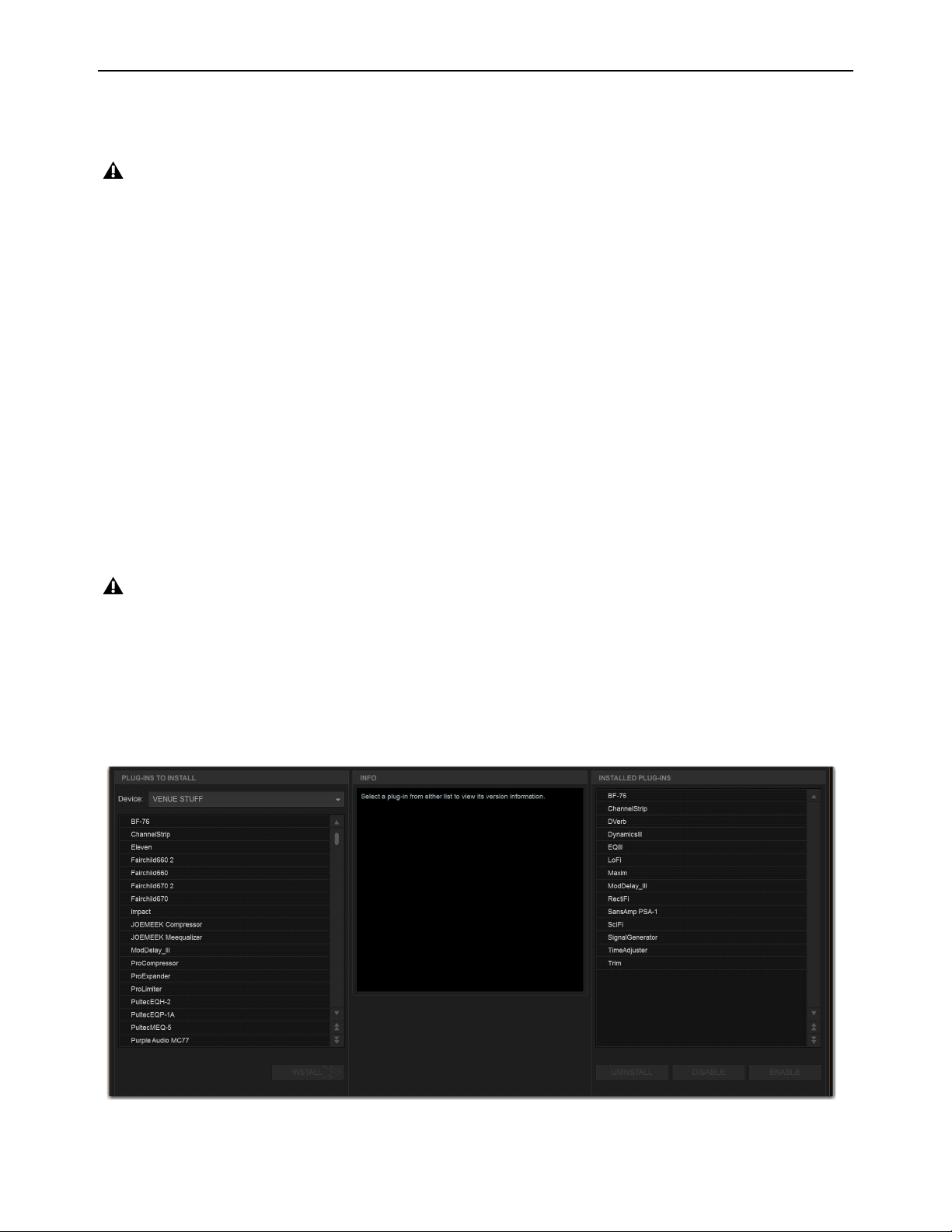
Plug-Ins 273
Installing and Authorizing Plug-Ins
Plug-Ins are installed on your system using a USB drive. Plug-in installers are transferred to your USB drive, then installed on the
S6L control surface. For Waves plug-ins, see
Transferring Plug-In Installers to USB
To transfer plug-in installers to a USB drive:
1 Make sure there is enough free space on the USB drive to accommodate all the software.
2 Unzip the downloaded software by doing the following, depending on your computer platform:
Mac
Double-click the ZIP file containing the software to unzip it.
Windows
Right-click the ZIP file containing the software, select Extract All... from the pop-up menu, and in the ensuing dialog
click Extract.
3 In the unzipped files, locate the “AAX Plug-Ins” folder.
4 Copy the entire “AAX Plug-Ins” folder to the top (root) level of the USB drive.
Installing Plug-Ins
To install a plug-in:
1 Put the system into Config mode.
2 Insert the USB drive containing the plug-in installer(s) into an available USB port on the S6L control surface.
3 On the external VENUE software screen, go to the Options page and select the Plug-Ins tab. The following two lists are shown:
Plug-Ins to Install
This list shows available plug-in installers. At the top of the list is the Device selector, which provides a pop-up
menu of available media sources. Plug-In installers are stored locally after plug-in installation, and appear as available items when
Previous Installs is selected from the Device selector. This lets you re-install plug-ins without the original plug-in installer.
Installed Plug-Ins
This list shows all plug-ins already installed on the system. The plug-ins shown in plain text are available to pro-
cess audio. Plug-Ins listed in italics are disabled and unavailable (see Enabling and Disabling Installed Plug-Ins).
Because installing plug-ins can interrupt audio throughput, always install plug-ins before a performance.
Plug-Ins cannot be installed using the USB ports on the E6L engine.
Options > Plug-Ins screen
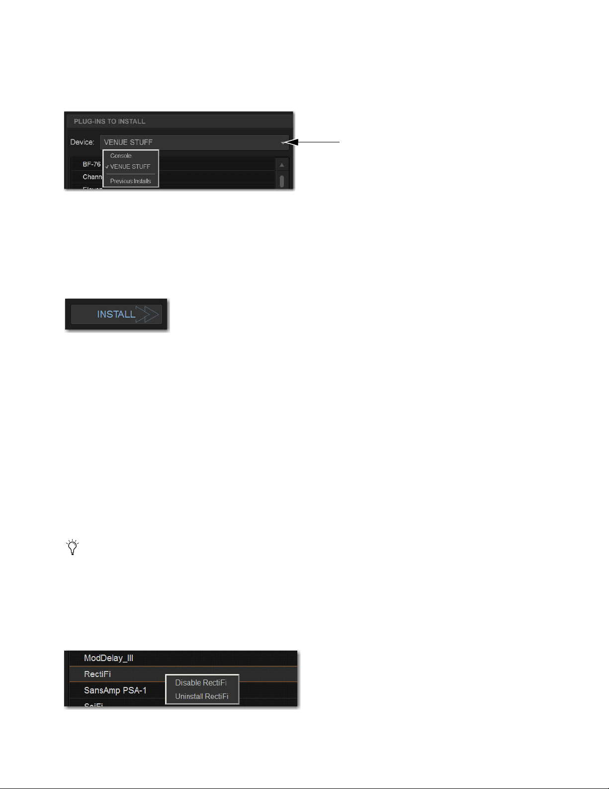
Plug-Ins 274
4 In the Plug-Ins to Install list, select the device selector pop-up menu and do one of the following:
• Choose Previous Installs to access any plug-in installers after a system update.
• Choose Console to access all factory-installed plug-in installers after a system update or a full system restore.
• Choose an external storage device, as available, to access plug-in installers on drives connected to the S6L control surface.
5 Select a plug-in from the Plug-Ins to Install list on the left by doing any of the following:
• Select a single installer so it is highlighted.
• Shift-touch to select multiple consecutive installers.
• Control-touch to select or deselect installers one at a time.
6 Select Install to install the selected plug.
7 When prompted, select Accept to accept the End User License Agreement (EULA) for the plug-in. The EULA for each plug-in
installed must be during installation accepted.
Once installed, the plug-in appears in the Installed Plug-Ins list on the right.
8 Repeat as necessary to re-install all plug-ins needed on the system.
Uninstalling Plug-Ins
Uninstalling a plug-in removes the plug-in from the racks but the installer remains in the Previous Installs cache, making it easier
to reinstall the plug-in at a later time without requiring the installer media.
The list of available plug-ins you see in VENUE software is updated automatically each time you load a Show file to keep plug-in
lists and menus uncluttered (see
Automatically Removing Plug-ins During Show Load.)
You can also remove or delete plug-ins and/or their installers manually. In order to completely remove and delete a plug-in and its
installer, you must explicitly delete the plug-in, as described in the following sections.
To uninstall a plug-in from the system but leave its installer available:
1 Put the system in Config mode.
2 Go to Options > Plug-Ins.
3 Touch-and-hold (right-click) the specific plug-in name from the right-hand list and choose the Uninstall option for the selected
plug-in.
Device selector pop-up menu
Plug-Ins Install button
Installing, uninstalling, and deleting plug-ins are not supported using the Standalone software.
Disable/Uninstall plug-in menu

Plug-Ins 275
To reinstall a removed plug-in:
1 Put the system in Config mode.
2 Go to Options > Plug-Ins.
3 Select the Device selector and choose Previous Installs from the menu.
4 Select the plug-in and choose Install. If the desired plug-in is not listed, it must be re-installed from a USB drive containing its
installer.
Deleting Uninstalled Plug-Ins
Once a plug-in is uninstalled, its installer can be deleted from the system. (Plug-ins which are currently installed cannot be deleted).
To completely remove a plug-in and its installer:
1 Put the system in Config mode.
2 Go to Options > Plug-Ins.
3 Select Previous Installs from the Device selector.
4 Touch-and-hold (right-click) the plug-in name and choose the Delete option for the selected plug-ins. The plug-in is removed
from the system, and the stored plug-in installer is removed from the Previous Installs list.
Installing Plug-Ins Manually
If a plug-in does not appear in the Plug-Ins to Install list, it may not have a fully compatible VENUE installer and must be manually
installed. This is required the first time you install the plug-in, and whenever you need to re-install a plug-in (such as after using
the System Restore software to update or reset the system).
To install a plug-in manually:
1 Make sure all sound systems are shut down or muted.
2 Insert the USB storage device with the plug-in installer into a USB port on the S6L control surface.
3 Go to the Options page and select the System tab.
4 Hold the Ctrl key and select Shutdown. Follow thee on-screen directions to exit to the Desktop.
5 Copy the plug-in installer to the disk partition called User Data.
6 Launch the plug-in installer application and follow any on-screen directions. If prompted, do not restart the system from a
plug-in installer. (Doing so will not harm the system, but will take longer, especially if you have multiple plug-ins to install man-
ually.)
7 Quit the installer application and eject the installer disc.
8 Select the Return to VENUE shortcut on the desktop to re-launch the VENUE software.
9 Go to Options > Plug-Ins. Verify that the manually installed plug-in appears in the Console list of available plug-ins.
Authorizing Plug-Ins
A core set of plug-ins are installed on your system. These plug-ins do not require any authorization. Other plug-ins, such as the S6L
plug-ins downloaded from your Avid account and paid plug-ins from Avid and our Development Partners, require authorization.
The S6L system supports iLok USB Smart Key authorization. Licenses that authorize the use of a plug-in are transfered from your
iLok account to your iLok. This lets you take your iLok and your plug-in licenses anywhere, to use your plug-ins on any system.
After installing a plug-in, the system re-creates the list of available plug-ins. Whenever the racks initialize, the system checks for
all installed plug-ins. If an iLok with a license for an installed plug-in is not connected to the S6L control surface, you will be
prompted to try a demo version, or authorize the full version of the plug-in.
A plug-in without a VENUE installer may still be compatible. Consult the plug-in manufacturer for compatibility information.

Plug-Ins 276
To authorize a plug-in:
1 When a plug-in authorization dialog appears, do one of the following:
• To try a demo of the plug-in, select Try, where available.
– or –
• To have the system recognize the required license on your iLok, select Authorize. Insert your iLok into any available USB port
on the S6L control surface when prompted.
2 Follow the instructions on-screen to complete the software authorization process.
Enabling and Disabling Installed Plug-Ins
The Installed Plug-Ins list shows Disabled plug-ins in italics. Plug-Ins can be manually disabled and enabled to manage DSP re-
sources, troubleshoot possible conflicts, and to manage plug-in availability.
To globally disable or enable a plug-in:
1 Select the plug-in name in the Installed Plug-Ins list, at the right of the Options > Plug-Ins page.
2 Touch-and-hold (right-click) the plug-in and select whether to disable or enable the selected plug-in. If assigned to any rack
slots, the plug-in will be displayed as unavailable and inactive.
Automatically Removing Plug-ins During Show Load
Plug-ins are verified during the Show file load procedure to streamline plug-in lists and menus by automatically removing unused
plug-ins (plug-ins that were once installed but subsequently uninstalled or disabled).
In addition, the plug-in lists can be reset manually using the Remove Unavailable Plug-ins command. Plug-ins which are not
available and not in use in the rack are automatically filtered from all plug-in menu lists when the show file is subsequently stored.
This filtered list is stored with the Show file.
Plug-ins which are not available but are in use will remain in the rack and display a warning icon indicating the plug-in isn’t in-
stalled or is disabled. Such plug-ins appear as italicized entries in the plug-ins menu lists.
Manually Removing Unavailable Plug-ins from the Racks
Unavailable plug-ins can be easily removed from rack slots using the Remove Unavailable Plug-Ins command.
To manually remove unavailable plug-ins:
1 Put the system in Config mode. Make sure the plug-in rack is fully initialized (the Status indicator displays OK).
2 Select the Plug-In Selector in any rack slot and choose Remove Unavailable Plug-Ins. This menu item is only available when
one or more unavailable plug-ins are present in the rack (indicated by a warning symbol in the rack slot).
3 Select Remove to confirm the operation, or select Cancel.
If you proceed with the removal:
• All unavailable plug-ins are removed from the plug-ins rack.
• The italicized entries for unavailable plug-ins are removed from all plug-in menu lists.
• All references to unavailable plug-ins are removed from the Insert Processing section of all affected channels, and the insert
point plug-in is set to
None.
• All references to unavailable plug-ins are removed from all snapshots.
The new, updated list of available plug-ins is subsequently saved to the Show file.
History File and Removing Plug-ins
A History file is written immediately before removing unavailable plug-ins from the rack, in order to provide a means of undoing
the operation.

Plug-Ins 277
Plug-in Version Checker
VENUE software includes a comprehensive database of plug-in information, and this info can be used to greatly simplify the pro-
cess of managing your VENUE plug-ins.
Use this feature to get version details and compatibility information for a plug-in prior to installing, or after it has been installed to
help diagnose or troubleshoot plug-in performance.
Version checking also warns you when you are about to downgrade a plug-in (install an older version over a newer version).
To view plug-in version information:
1 Go to Options > Plug-Ins.
2 Select a plug-in from either list (Plug-Ins to Install, or Installed Plug-Ins).
The Info pane displays details about the currently selected plug-in, including whether a newer version of the plug-in is available.
If a new version is available, you can find out whether it is a recommended update or a critical update. The following dialogs appear
if you choose to install older plug-ins:
• If you choose to install a plug-in for which there is a critical or recommended update, a dialog appears asking you to confirm the
installation procedure.
• A similar dialog appears when attempting to replace an installed plug-in with an older version of the same plug-in. Follow the
instructions on-screen to install anyway, or cancel.
Using System Info to View Plug-in Version Information
Plug-in version information is included in exported System Info data.
The Plug-in sections of the exported System Info file show critical and recommended updates, with links to sites to download or
check for newer versions.
To use System Info for Plug-In Version Maintenance:
1 Insert a USB storage device into any available USB port on the S6L control surface engine.
2 Go to Options > System.
3 Select the Info button.
4 Do any of the following:
• If you have more than one USB device connected, make sure the correct USB device is selected. If it is not, select Next Disk
to cycle through each available disk until the correct one is selected.
•Select Save to proceed and export system info to the selected USB device.
•Select Cancel to dismiss the dialog without exporting.
5 Select OK to confirm the export procedure.
6 Remove the USB device. Transfer the exported file to a personal computer for printing, formatting, archiving or distribution.
7 If viewing the System Info document from a computer with Internet access, use the included links to check for plug-in updates.
In addition to using the plug-in version checker, also check
the VENUE plug-in tabs on the Avid website (www.avid.com)
for the most up to date information
Version information is not shown for a multi-selection. Select
an individual plug-in to view its version information.
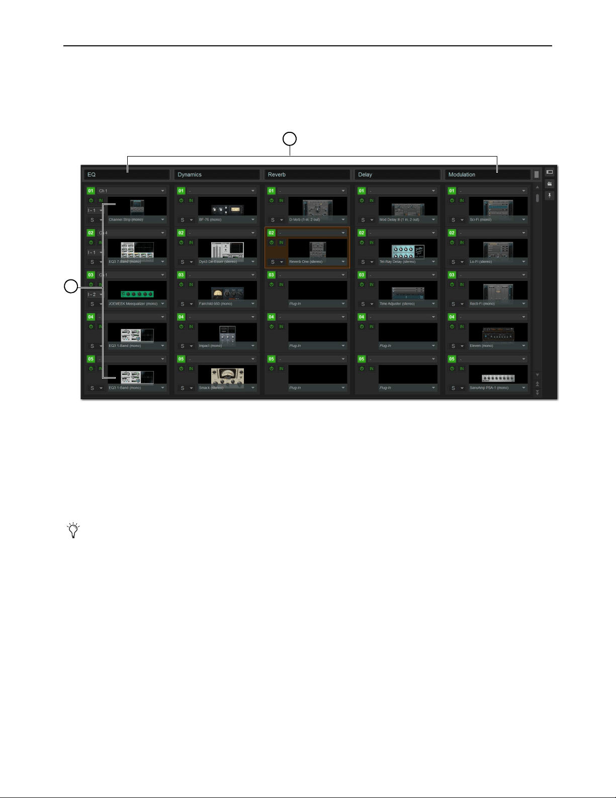
Plug-Ins 278
Plug-In Racks
The Plug-Ins page provides five plug-in racks. Each of the racks has slots into which you can load a plug-in. The different racks
can be viewed all at once, individually, and in varying zoom levels. You populate the racks by assigning plug-ins in rack slots.
The number of racks and slots vary with different S6L systems.
Naming Plug-In Racks
You can name and rename each rack as needed.
To rename a plug-in rack:
1 Double-tap the rack name to highlight it on-screen.
2 Type a new name and press Enter. To return a rack to its default name, leave the name blank and press Enter.
Rack Views
The Plug-Ins page can be displayed in Full or Zoom views. Either view can show a Collapsed view of 10 rack slots.
Full View
The default view of the rack screen is Full view, in which five racks are shown at a time. This screen provides access to all rack slot
controls and shows an icon representing each assigned plug-in. This lets you quickly see what plug-ins are available, and adjust
their routing.
Plug-In racks (1) and rack slots (2), Full view, with custom rack names shown
Plug-Ins can be placed in any rack slot. Use the different racks to organize processing functions such as Dynamics, Vocal FX,
Reverb, or Group Inserts.
1
2
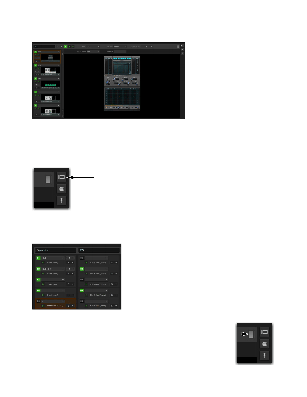
Plug-Ins 279
Zoom View (Plug-In View Mode)
In Zoom view, a single rack remains on-screen to the left, and the rest of the screen displays the targeted plug-in.
To toggle Full or Zoom view modes, do one of the following:
Select the View toggle switch (upper right corner of the rack).
– or –
Double-tap a plug-in icon in any rack view to open that plug-in window in Zoom view.
Collapsed View
You can collapse the plug-in racks so ten rack slots per row are shown in Full of Zoom view.
To toggle between Expanded or Collapsed rack slot views:
Select the Expand/Collapse button (upper right corner of the rack).
Zoom view, with a plug-in window open on-screen
View toggle button
Full view, collapsed
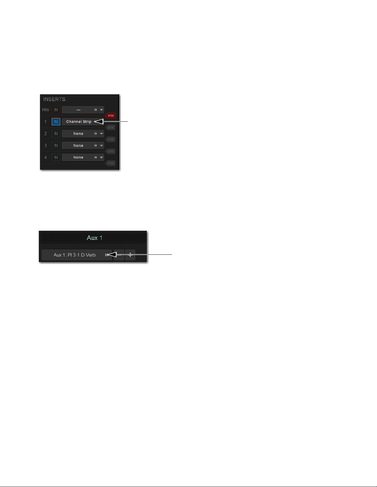
Plug-Ins 280
“Jump To” Plug-Ins
You can “jump to” a specific plug-in insert from the Input and Output pages to adjust it on-screen in the Zoom view of the Plug-In
page.
To jump to a plug-in insert from the Inputs or Outputs screen:
1 Select a channel to display it in the Inputs or Outputs screen.
2 Select the plug-in name (or None if no plug-in is inserted in that slot) shown in the channel Inserts section.
To jump to a bus-fed plug-in:
1 Bank to the input channel the plug-in output is assigned to, or bank to the output feeding the plug-in.
2 Attention the channel to display it in the Inputs or Outputs screen.
3 Select the routing displayed beneath the Channel Name.
Plug-Ins Screens and Channel Selection
When jumping to a plug-in, display depends on the type of plug-in routing, as follows:
Channel Inserts
If the Plug-Ins screen is in Zoom view while you attention a channel, the last attentioned plug-in for that channel
is automatically targeted and displayed in the Plug-Ins screen.
Bus-Fed Plug-Ins
If no plug-ins are inserted on a channel (such as when returning a bus-fed plug-in to an input channel), the
plug-in feeding that input channel is displayed.
Jumping to a plug-in on a channel insert
Jumping to a plug-in on a bus

Plug-Ins 281
Pinning a Plug-In View
You can decouple the plug-in view for consistent and constant access to a single plug-in on-screen, while still being able to select
and adjust other plug-ins from the control surface. Pinning a plug-in view is useful any time you want to always display an import-
ant plug-in (such as an analysis plug-in or primary EQ).
To pin a plug-in view:
1 Bring the desired plug-in into the Zoom view (use the channel Select and Insert Mode switches, double-tap the desired plug-in
from the rack, or jump to the plug-in from the Inputs or Outputs page).
2 Select the Push-Pin icon in the upper-right of the screen (the icon is located just to the left of the Presets and View Toggle
icons.
• When enabled, the Push-Pin icon appears lit. This indicates that the current plug-in will remain on-screen and will not lose fo-
cus, even if another channel is targeted.
• When not enabled, the Push-Pin icon appears unlit. Plug-in view follows control surface selections.
Identifying Rack Slots
In the plug-in racks, the slot of the targeted plug-in is bordered in orange.
Push-Pin icon
Targeted plug-in in a rack
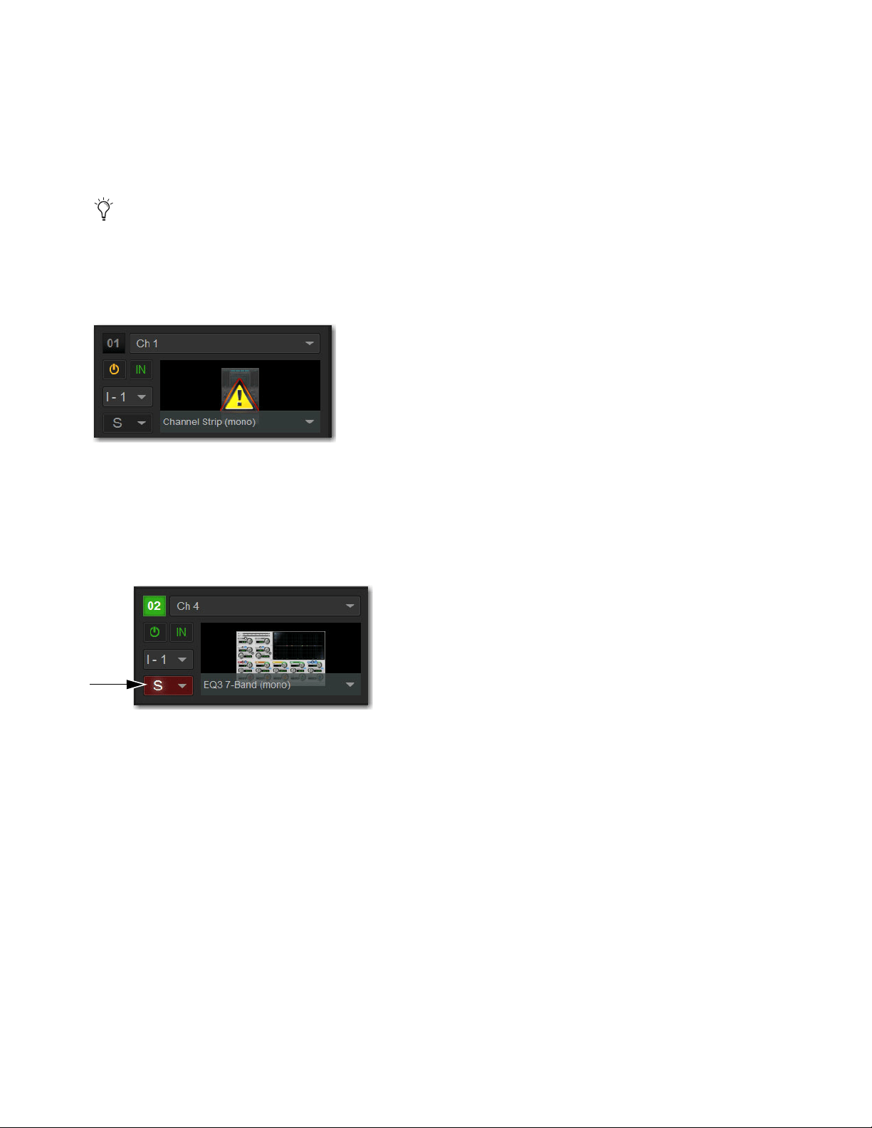
Plug-Ins 282
Display of Unavailable or Inactive Plug-Ins
It is possible for a plug-in to be displayed in a rack slot but be unavailable for channel and bus processing. This can occur in any
of the following circumstances:
• There are not enough DSP resources available for the plug-in.
• The assigned plug-in is part of the show file but is not installed on the current system.
• The plug-in has been disabled manually.
Unavailable Plug-Ins
When a plug-in cannot be used because of insufficient DSP resources, because it is disabled, or because it is not installed on the
system, a warning icon is shown in front of the affected plug-in. The plug-in icon is grayed out, and the rack slot Power switch dis-
plays a yellow switch LED.
For more information, see
Installing and Authorizing Plug-Ins.
Scope Indication in the Plug-Ins Page
The Plug-In Rack provides visual indication whenever a plug-in is scoped in the currently targeted snapshot. The Snapshot pop-up
menu turns red whenever that plug-in is scoped by the currently targeted snapshot.
For more information, see Plug-In Presets and Snapshots.
To view DSP resource allocation, see 2 – HDX DSP.
Indication of an unavailable plug-in
Indication of a scoped plug-in
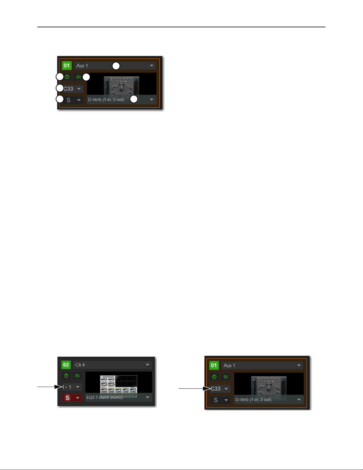
Plug-Ins 283
Rack Slots
Each rack provides ten plug-in slots. You can assign any installed plug-in to any available rack slot.
Rack Slot Controls
Each rack slot provides the following controls to select and manage plug-ins:
1 – Power (Config Mode Only)
Power turns the rack slot on or off. When off, the plug-in consumes no DSP.
2 – In/Out (Bypass)
The In/Out switch takes the rack slot in or out of circuit (bypasses the slot and any plug-in assigned to it).
3 – Input Selector
The Input selector displays a menu of input sources for a plug-in. Use this to designate the plug-in as a channel insert or a bus pro-
cessor by choosing from the Inserts or Bus sub-menus. For more information, see Routing Plug-Ins.
Once a plug-in has been routed, its input source is displayed in the Input area of each rack slot, as follows:
• If the plug-in is being used as an insert, the channel or bus name and number is shown, for example, Kick (Ch 1) or Aux (1–2).
The Channel Insert/Bus Output selector automatically switches to Channel Insert mode, showing the insert point occupied by
the plug-in.
• If the plug-in is on a bus, the selected bus source is shown in the Input selector, for example, Aux 1 or Grp 1. The Channel In-
sert/Bus Output selector can be used to assign the output routing of the plug-in to a channel or bus.
4 – Channel Insert or Output Selector
The Channel Insert/Output selector displays different choices depending on whether the plug-in is being used as a channel insert,
or as a bus processor, as follows:
• If the plug-in is being used as a channel insert, the Channel Insert Selector shows the four insert points on that channel (1–4).
The letter “I” is shown before the insert number (for example, I–1 indicates the current plug-in is inserted into the first insert
position on its channel).
• If the plug-in is being used as a bus processor, the selector is an Output selector, used to select the destination for plug-in out-
put,. When the plug-in is routed, the selector shows the channel to which the plug-in output is assigned.
A rack slot and its controls, with an assigned plug-in shown
A rack slot shown an inserted mono plug-in (left) and a stereo plug-in assigned as a bus processor (right)
1
2
3
4
56

Plug-Ins 284
5 – Plug-In Selector
The Plug-In selector displays a list of available plug-ins to load into that rack slot. Plug-Ins are arranged by process type (such as
EQ, Dynamics, and Delay). For more information, see
Routing Plug-Ins.
6 – Snapshots Menu
The Snapshots menu provides tools to manage snapshot-related plug-in features from within the Plug-Ins screen. Using the Snap-
shots menu, you can quickly check to see which existing snapshots refer to the current plug-in, as well as create, update, or remove
snapshots.
Sidechain Selector
The Sidechain selector appears near the top of the Zoom view when you select a plug-in that supports side-chain or “key” input.
In Config mode, the Sidechain selector lets you establish a side-chain routing to the plug-in. Once established, you can route and
re-route side-chain signals in both Config and Show mode. For more information about side-chain signals, see
Sidechain Routing.
Assigning Plug-Ins to Rack Slots
Before a plug-in can be used to process audio, it must be assigned to a rack slot. Once assigned, you can use the plug-in as a channel
insert or bus processor.
To assign a plug-in:
1 Put the system into Config mode.
2 Go to the Plug-Ins page.
3 Select the Plug-In Selector on an empty rack slot. (You can also use an already assigned rack slot to change a plug-in assign-
ment.).
4 Choose an available plug-in from the Plug-In selector sub-menus. Only plug-ins that are installed will be available.
If the plug-in is not installed or there are insufficient DSP resources available, the plug-in will appear as unavailable, or inactive.
Before a plug-in can be assigned, it must be installed. See
In-
stalling and Authorizing Plug-Ins.
The Plug-In selector
Plug-In selector menus
Place the cursor over the plug-in to display a Tool Tip that explains why the plug-in is unavailable or inactive.
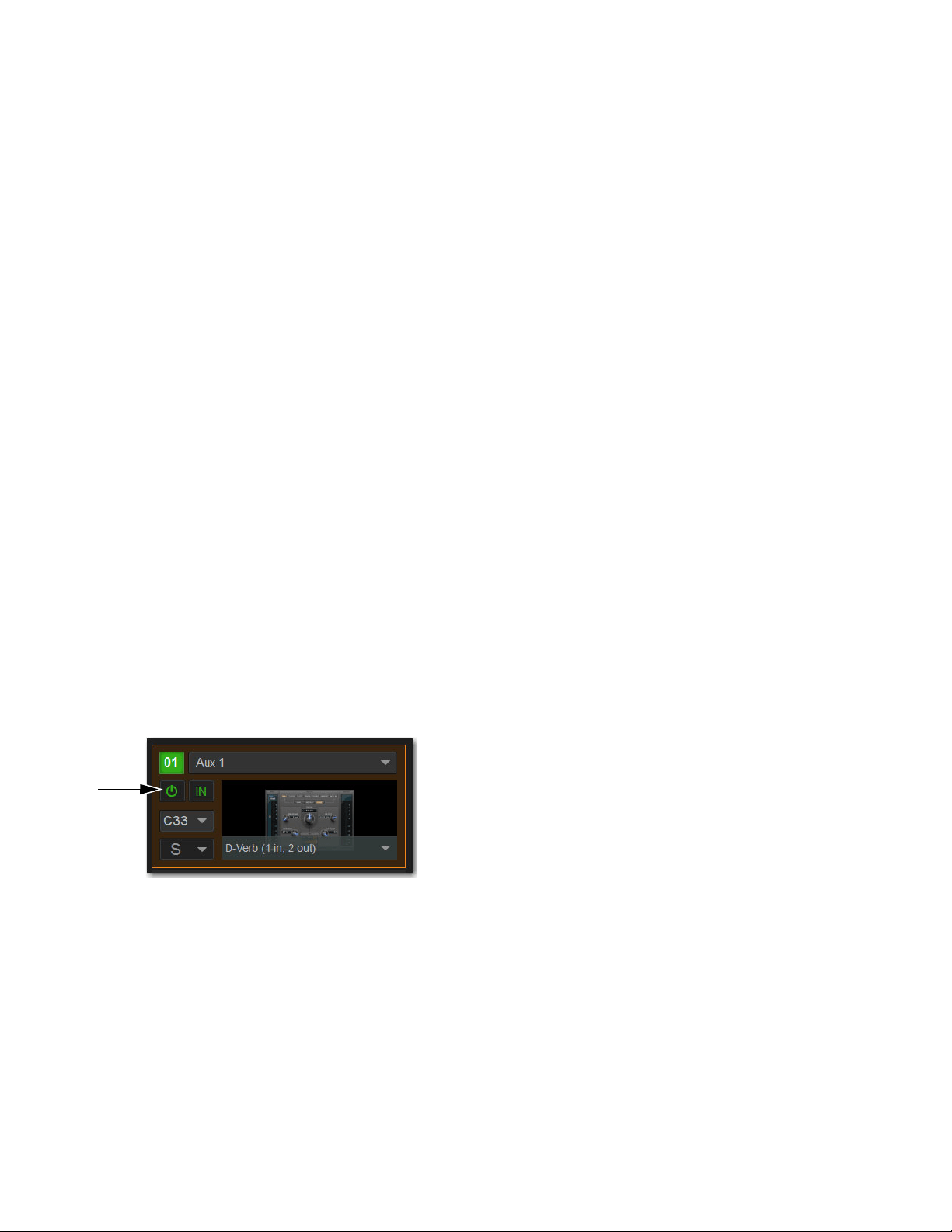
Plug-Ins 285
Plug-In Formats (Mono/Stereo)
Plug-Ins inserted on input channels must be symmetrical (in other words, mono in/out or stereo in/out). Plug-Ins on buses can be
asymmetrical (mono-in/stereo or multichannel out).
Mono
Can be used as inserts only in mono strips or mono Auxes, mono Groups, or Matrix buses or on the C/M bus.
Stereo
Can be used as inserts in stereo strips, stereo-linked Auxes, and stereo Groups.
Other (Mono In/Stereo Out)
Can be used on buses for delay, reverb, and similar processing.
Moving and Copying Plug-Ins
(Config Mode Only)
To move or copy a plug-in from the rack, drag the plug-in icon to a new rack slot. A pop-up menu appears offering two choices:
Copy Plug-In Here, or Move Plug-In Here.
Moving a Plug-In
When you move a plug-in from one rack slot to another, the plug-in type, in/out state, power on/off, current plug-in settings, and
routing are maintained. In addition, all associated snapshots are updated to reflect the new rack position.
Copying a Plug-In
When you copy a plug-in to a new rack slot, the source plug-in type, in-circuit state, active state, and current plug-in settings are
copied to the destination rack slot. However, the source plug-in routing is not copied. In addition, plug-in snapshots are not copied.
Overwriting An Existing Plug-In
When either moving or copying, if there is an existing plug-in located in the destination rack slot, that plug-in is deleted. When the
plug-in located in the destination rack is deleted, any routing or references in existing snapshots to the deleted plug-in will be au-
tomatically cleared.
Activating and Deactivating Plug-Ins
To activate and deactivate a plug-in:
Select the appropriate rack slot Power switch. When active, the Power switch lights green. When a plug-in is unavailable (and
inactive), the Power switch lights yellow.
Rack slot power switch
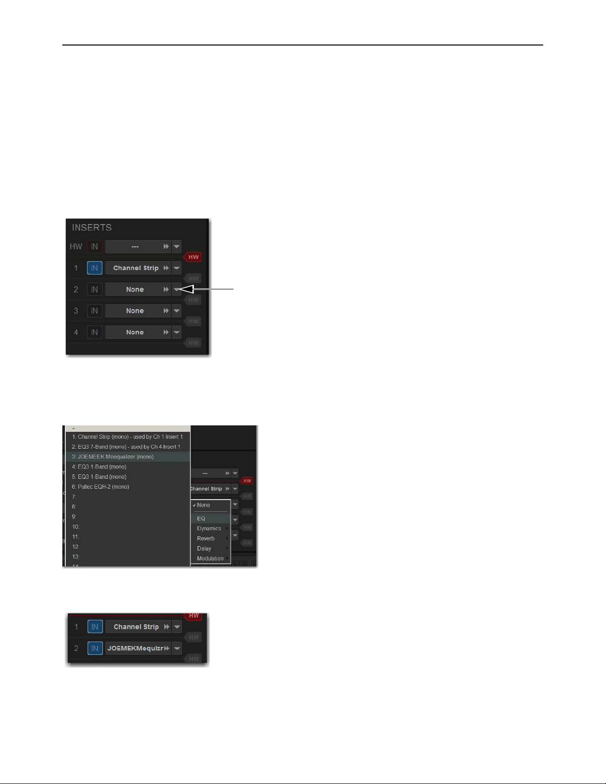
Plug-Ins 286
Routing Plug-Ins
After a plug-in has been assigned to a rack slot, you can specify its routing. Plug-In routing determines whether the plug-in is used
as a channel insert or as a bus processor.
Inserting Plug-Ins on Channels
Four slots per channel are provided for plug-in inserts. Signal from the channel is routed to the insert and returned to the same chan-
nel. You can assign plug-ins to specific channel insert points from the Plug-Ins screen or from the Input screen.
To insert a plug-in on a channel from the Inputs or Outputs page:
1 Go to the Inputs or Outputs page.
2 Select the first available Inserts slot selector.
3 Choose an available plug-in from the rack sub-menus. All currently available plug-ins of a compatible mono/stereo format are
listed in the sub-menus. Plug-Ins that are unavailable are listed in italics. Plug-Ins that are currently inserted on other channels
are shown with their insert assignment.
4 The plug-in appears in the Inserts list for that channel.
5 To open the window for an inserted plug-in, select its name in the channel Inserts list.
The Inserts selector
Plug-in rack sub-menus
An assigned channel insert
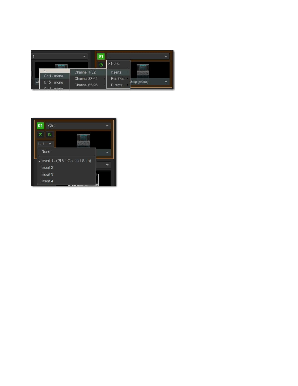
Plug-Ins 287
To insert a plug-in on a channel from the Plug-Ins page:
1 Make sure the plug-in is already assigned to a rack slot. (See
Assigning Plug-Ins to Rack Slots.)
2 In the rack slot, select the Input selector and choose a channel from the Inserts sub-menus.
The rack slot automatically identifies and connects to the first available insert slot on the selected channel. The Channel Insert se-
lector shows the current insert position. In the figure below,
I-1 indicates the plug-in is in the first insert Inserts slot of channel 1.
If no insert slots are available on the channel, the selector displays a question mark.
Inserts sub-menus
Channel Insert menu
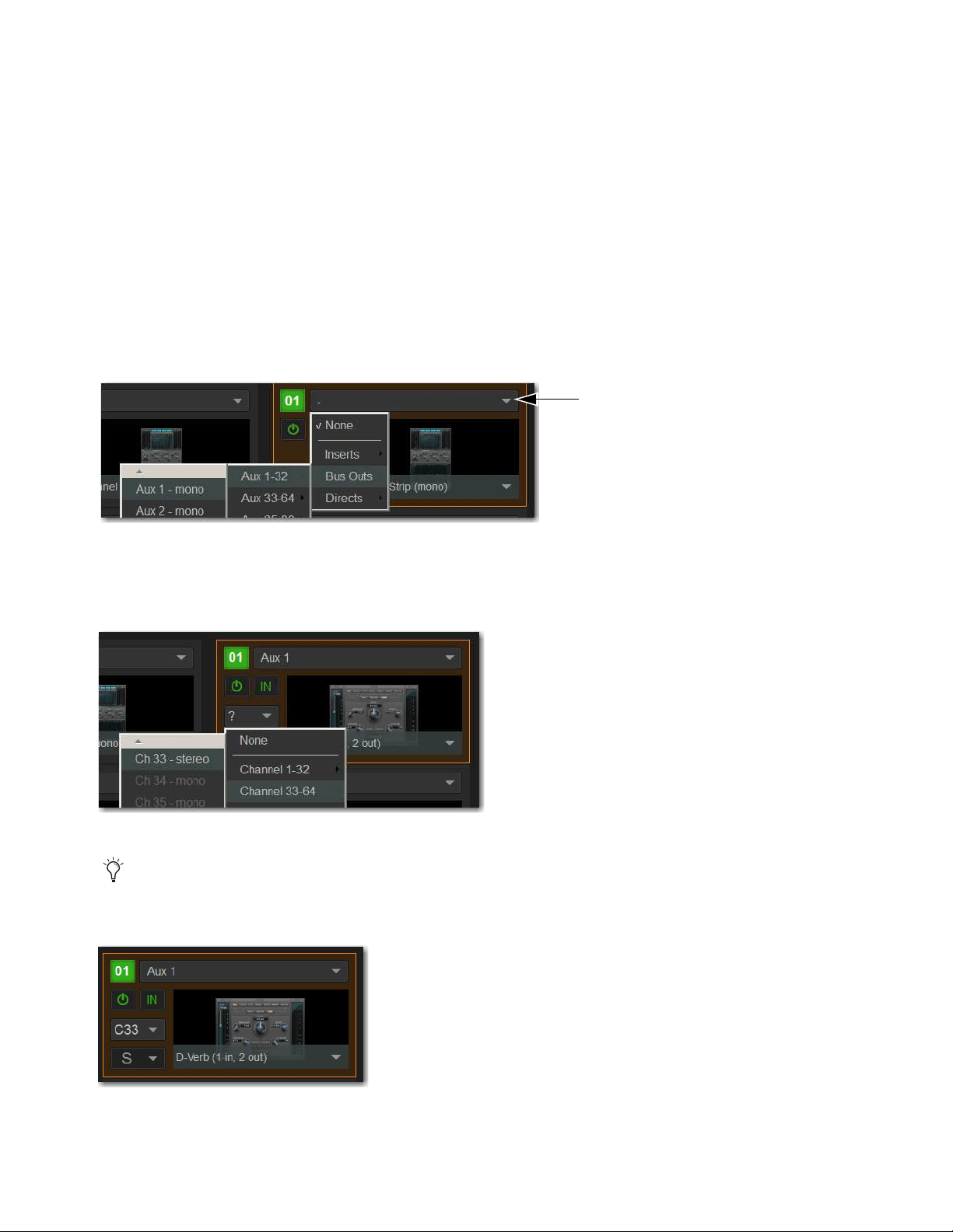
Plug-Ins 288
Routing Plug-Ins as Bus Processors (Effect Send/Return)
Plug-Ins can be used on buses for send-and-return processing with effects such as reverb and delay. A plug-in is configured for bus
processing by assigning an Aux, Group, Matrix, Main, Monitor output, or a Direct Out as the plug-in input source, then assigning
the output of the plug-in to an input channel, or to a hardware output, as follows:
• Return bus-fed plug-ins to an input channel to establish an effects send-and-return path.
• Route bus-fed plug-ins to a hardware output for specialized processing needs (such as feeding an external crossover).
You assign plug-ins for bus processing from the Plug-Ins screen.
To use a plug-in as a bus processor:
1 Go to the Plug-Ins page.
2 Make sure the plug-in is installed and assigned to a rack slot.
3 Select the Input selector at the top of the corresponding rack slot, choose Bus Outs, then choose the desired output bus from the
sub-menus.
4 Select the Plug-In Output selector and choose an input channel or a hardware output. Depending on the plug-in's output format
(mono/stereo), available channels are lit (available for assignment) or unlit (unavailable for assignment) depending on their for-
mat.
When a bus-fed plug-in has both its input source and output assigned, it appears similar to the following in the rack:
Input selector and sub-menus
Assigning plug-in output to an input channel
When routing a plug-in with a stereo output to an input channel, make sure the input channel is a stereo channel. See
Make Se-
lected Mono Strips Stereo/Make Selected Stereo Strip Mono.
An assigned bus-fed plug-in shown in the rack
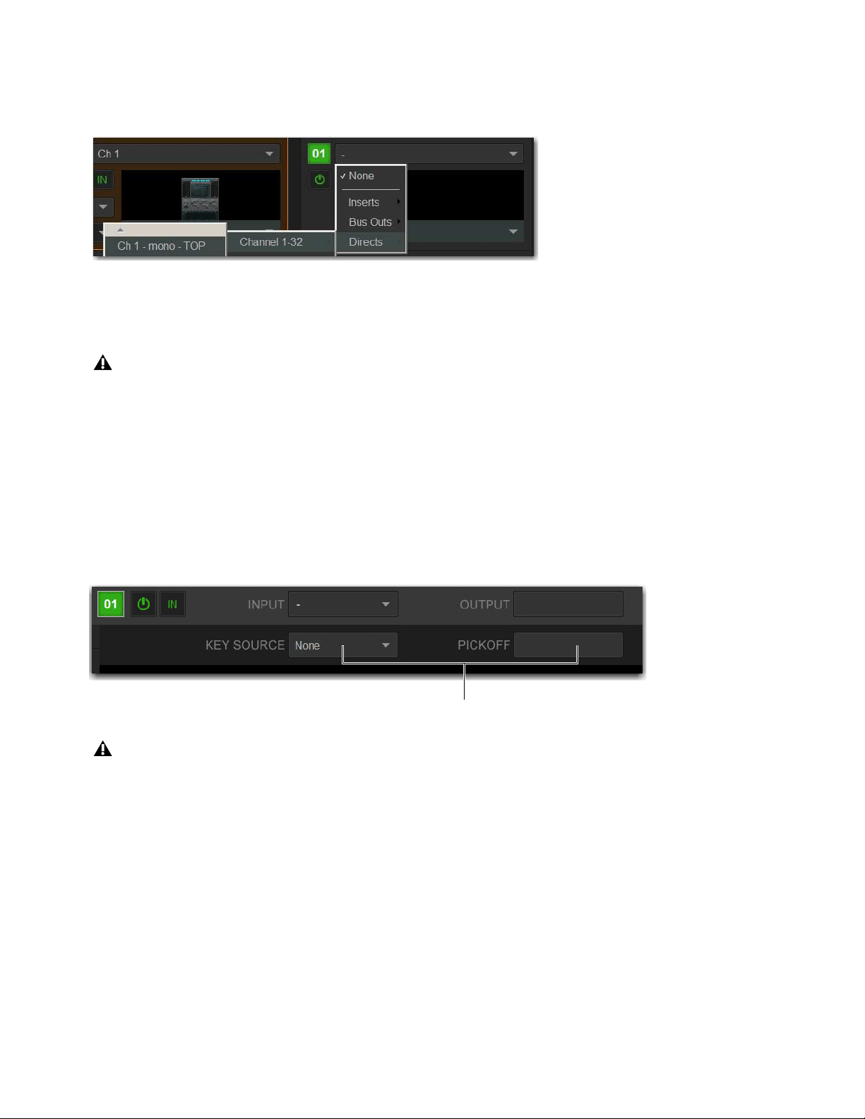
Plug-Ins 289
Routing Channel Direct Outs to Plug-Ins
You can route the Direct Outs to plug-ins. This lets you directly feed plug-ins from individual channels to preserve Aux buses for
other uses, with control over send level using the channel Direct Out level control.
When a channel Direct Out is routed to a plug-in, it follows the pickoff setting for that specific Direct Out (as set in the Patchbay),
and is applied in addition to any other assignment made for that Direct Out. This makes it possible to use a channel’s Direct Out
to route that channel to both a Pro Tools recording option and to a plug-in.
Sidechain Routing
S6L supports sidechain (key) processing for plug-ins that support sidechain triggering. The Sidechain selectors appear across the
top of the Plug-Ins page in Zoom view for the targeted plug-in.
To assign side-chain routing to a plug-in:
1 Target a plug-in that supports sidechain processing in Zoom view of the plug-in.
2 Choose the side-chain source signal from the Key Source pop-up menu.
3 Choose the pickoff point (tap) for the side-chain signal from the Source Pickoff pop-up menu.
Assigning a channel Direct Out as a plug-in input source in the Plug-Ins page
If you do use a Direct Out to feed both a hardware output such as a Pro Tools recording option as well as a plug-in, be aware
that any adjustments to that Direct Out affect both the output signal and the signal fed to the plug-in.
Sidechain controls
Side-chain routing is not stored in snapshots.

Plug-Ins 290
Adjusting Plug-Ins on the External Screen
You can adjust plug-ins on the Plug-Ins page.
To adjust a plug-in on-screen:
1 Attention a channel.
2 Go to the Plug-Ins page.
3 Double-tap a plug-in icon in any rack view to open that plug-in window in Zoom view.
4 Adjust the parameters for the plug-in appearing in the window as desired.
Bypassing Plug-Ins
Plug-Ins can be bypassed on-screen in the Inputs or Outputs page and from the Plug-Ins page.
To toggle a plug-in on/off (in/out of circuit):
1 Select the channel on which the plug-in is inserted.
2 Go to the Inputs page and select the in/out button next to the desired plug-in to toggle it in/out of circuit. When the button LED
lights, it indicates that the plug-in is in-circuit. When unlit, the plug-in is out-of-circuit (bypassed).
You can also adjust plug-ins using the CKMs in Channel Control mode. See
Adjusting Plug-Ins on the Control Surface
for more information.
An engaged plug-in (top) and a disengaged plug-in (bottom)
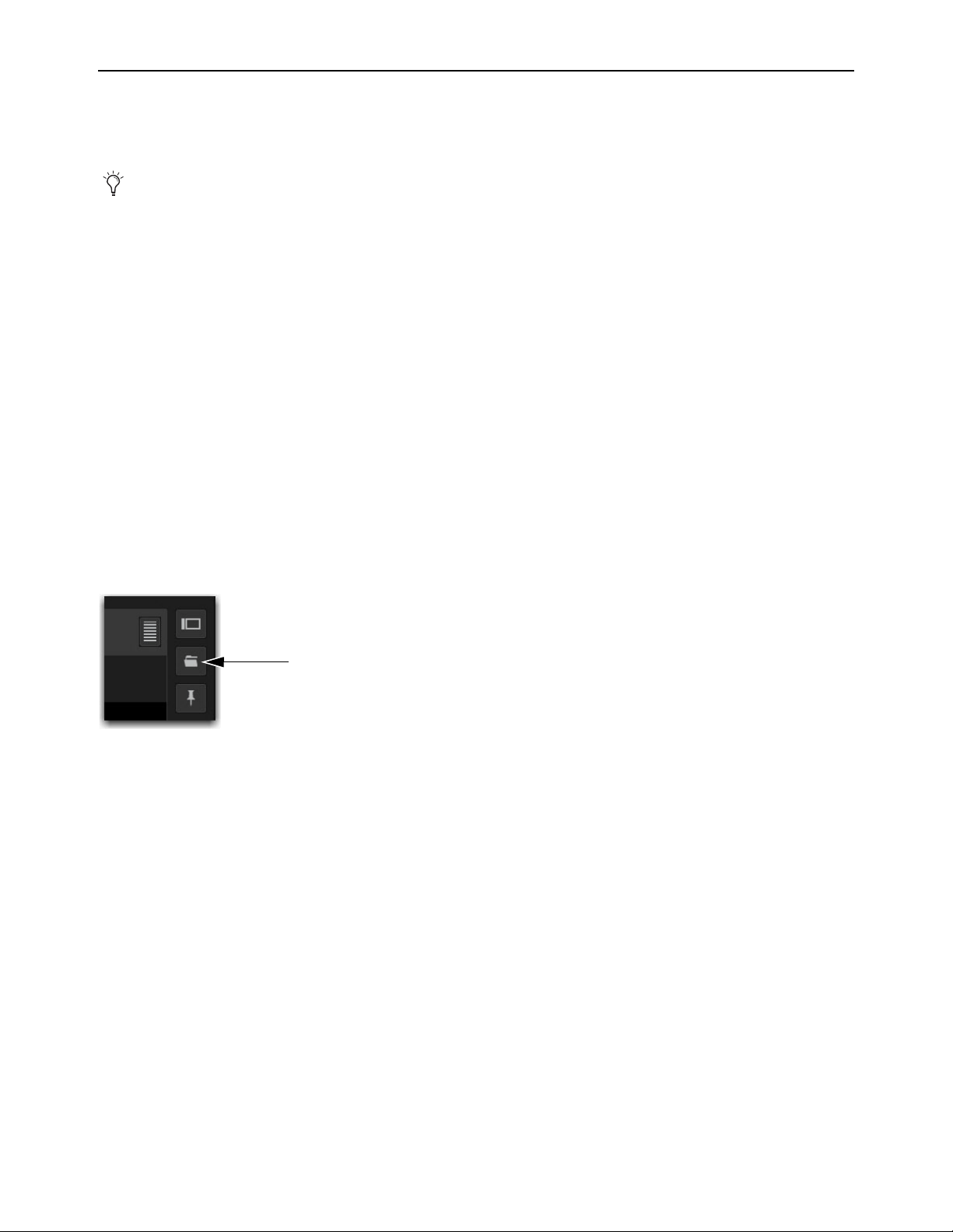
Plug-Ins 291
Plug-In Presets and Snapshots
You can save and load plug-in Presets files to import, export, and transfer plug-in settings files.
Snapshots can also be used to automate changes to plug-in routing and settings.
Plug-Ins and Presets
Presets are files that you can create to save, load, archive and transfer custom plug-in settings. You can then create your own Preset
folders to organize Preset files. Preset folders and files can be transferred using the Filing page.
To create a custom Presets folder:
1 Go to the Filing page and select the Transfer tab.
2 Select the Preset Folders icon.
3 Select the New button at the left of the screen.
4 Do one of the following:
• To leave the folder at its default name, press Enter.
– or –
• Type a new name and press Enter.
To save a Preset:
1 Adjust the plug-in parameters as desired.
2 On the Plug-Ins page, select the Presets icon.
3 In the Presets window, select New.
4 Enter a custom name for the Preset.
To load a Preset into a plug-in:
1 Make sure the presets are already transferred and available on the current system. (Many plug-ins come with factory presets that
will be installed along with the plug-in.)
2 Select the channel containing the plug-in, and target the desired plug-in.
3 Select the Presets icon in the Plug-Ins screen.
4 Select a preset name in the Presets list to preview it. With the Presets list displayed, do any of the following:
• To scroll through the list, press Up or Down arrow keys on your computer keyboard.
• To load a preset and close the Presets list, double-tap a name in the Presets list.
•Select
Cancel to close the Presets list without changing settings.
Presets can be applied to multiple Shows, while snapshots apply only to the Show file in which they are stored.
Plug-In Presets icon

Plug-Ins 292
Plug-Ins in Snapshots
Snapshots can automate plug-in settings, including routing, and in/out state. (Side-chain routing is not supported in Snapshots.)
Snapshots can also store and recall Tempo.
Each rack slot on the Plug-Ins page provides a Snapshot menu, with shortcuts for common snapshot-related tasks:
• Create a new snapshot
• Add one or more plug-ins to the MIDI/Plug-Ins list, and automatically re-scope the snapshot to include plug-ins.
• Remove plug-ins from one or more snapshots
Snapshots Containing this Plug-In
Lists all currently loaded snapshots referencing the plug-in, in sequential order. Choose a snap-
shot to load it. (This menu option is useful for targeting snapshots while editing plug-in racks.)
Create New Snapshot Containing this Plug-In
Adds a new snapshot to the snapshot list in which only plug-ins are scoped. This
snapshot is inserted immediately after the currently targeted snapshot, which may not necessarily be the last snapshot. The snapshot
is named to reflect the plug-in rack position, for example: “PI 1-1: Reverb One” is a Reverb One plug-in assigned to rack 1, slot 1.
Add (or Update) this Plug-In to Snapshot
Adds a plug-in reference, with current settings, if the currently targeted snapshot does
not already reference this plug-in. If the currently targeted snapshot already references this plug-in, the choice is Update (see next).
If multiple snapshots are selected, this command changes to “Add Plug-In to Selected Snapshots” for batch-assignment.
Update this Plug-In in Snapshots
Updates snapshots with current settings, if the currently targeted snapshot (or currently selected
snapshots) already references this plug-in.
Remove this Plug-In in Snapshot
Removes reference to this plug-in from the currently targeted snapshot, or from all currently se-
lected snapshots.
Tempo Settings in Snapshots
Each snapshot can store a custom tempo value. You can use the Tempo Enable icon to enable or disable tempo recall when the as-
sociated snapshot is recalled, letting you automate delay times in plug-ins that support Tempo Sync. See
Adding Tempo Data to
Snapshots.
Plug-In DSP Usage
Plug-Ins utilize DSP resources when they are assigned to a rack slot, and that rack slot is powered on. Each HDX DSP card installed
in an E6L engine provides 18 DSPs for plug-in processing.
Plug-In availability is limited to available DSP resources. Certain plug-ins use more DSP resources than others. You may not be
able to instantiate a plug-in if there are not enough DSP resources available. You can turn off unused plug-ins to reclaim their DSP
by making them inactive, or by removing them from the system.
You can view plug-in DSP usage on the Options > Devices page.
To view plug-in DSP usage:
1 On the external screen, go to Options > Devices.
2 In the HDX DSP section, select a tab 1–4 to view currently active plug-ins and the DSPs they are allocated to on the correspond-
ing HDX TDM Mix Engine card.
Snapshots do not store or recall Presets. Snapshots store plug-in settings as they were when the Snapshot was created or saved.
See
Adding Plug-In Data to Snapshots.

Plug-Ins 293
Plug-In Levels
Meter levels on the S6L system are displayed in dBVU, with 0 dBVU =+4dBu analog out = –20dBFS.
Internally, the S6L system provides up to 32-bit processing for built-in EQ, dynamics, and plug-ins, with level matching circuitry
and logic ensuring maximum fidelity and sonic performance throughout the entire signal path. Due to variances in how plug-in me-
tering is implemented by different manufacturers, performance may vary with regard to plug-in gain reduction meters and their rel-
ative levels.
When using side-chain routing, be aware of potential level differences between input channel pickoff points. For more information,
see
Sidechain.
Plug-In Latency and Processing Delay
Plug-In latency includes processing delay of the plug-in itself plus routing delay, as follows:
• Instance delay: 2 samples per plug-in
• DSP routing delay: 3 samples
Viewing Plug-In Latency
Cumulative channel processing delay can be viewed by touching-and-holding (right-clicking) the Inserts area of the selected chan-
nel. The cumulative delay includes latency reported by all inserted plug-ins, signal routing and the known hardware insert delay,
if applicable.
Individual plug-In processing delay can be seen by touching-and-holding (right-clicking) the plug-in icon in the rack. Use the num-
ber reported when calculating latency for manual delay compensation.
Examples
If there is only one plug-in on a channel, the total delay will be the amount of plug-in latency + 2 + 3. (2 samples for the one plug-in
instance, plus 3 samples for the DSP routing to the racks and back.)
If you have two plug-ins on a channel or bus, the delay will be plug-in #1 latency + 2 + plug-in #2 latency + 2 + 3. If plug-in #1
has 12 samples of latency, and plug-in #2 has 15, total latency will be 34 samples (12 + 2 + 15 + 2 + 3).
Initializing the Plug-In Racks
The racks are initialized (or re-initialized) whenever the system is first powered on, whenever the system is restarted, after install-
ing a plug-in, and after disabling or re-enabling a plug-in.
While the racks are initializing, they are offline and do not process audio. Avoid performing any Filing or Transfer functions until
the racks are finished initializing. Rack status is displayed on-screen in the banner display.
Cumulative process delay
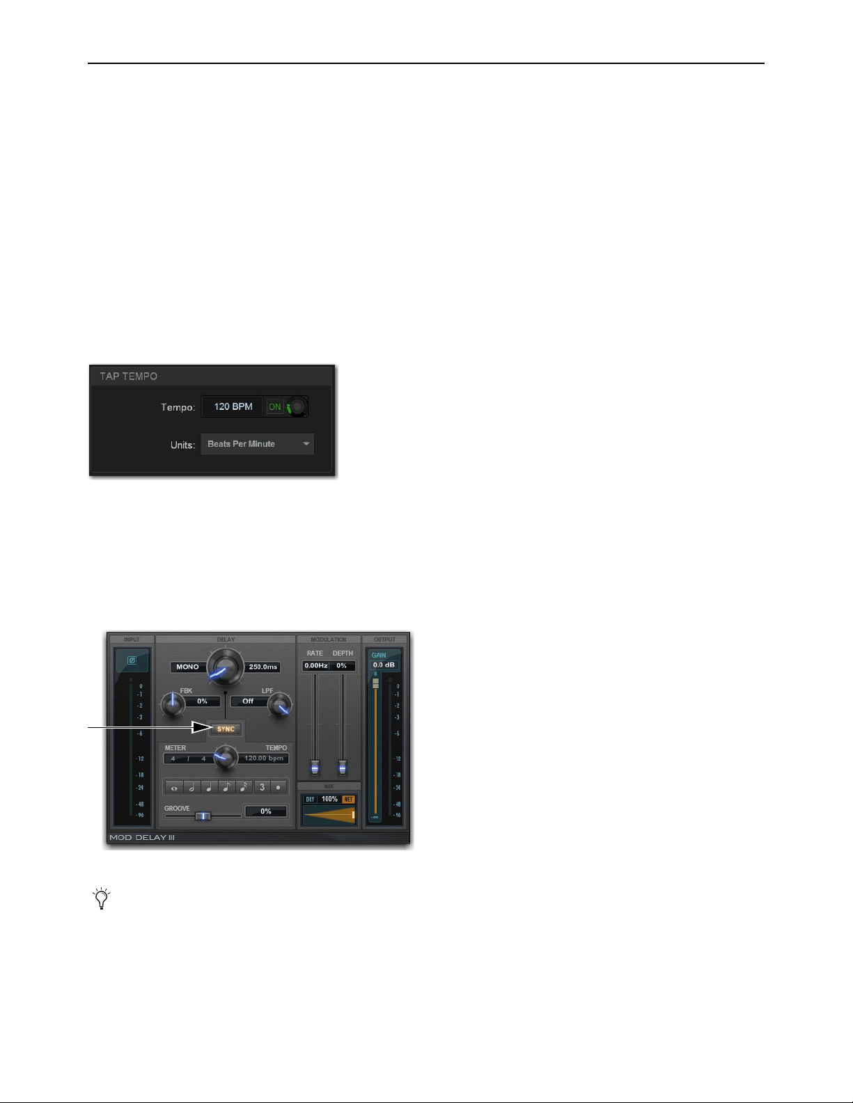
Plug-Ins 294
Tap Tempo for Plug-ins
Tap Tempo lets you quickly establish a system tempo to use as a beat clock for delay and echo plug-ins that support Tempo Sync.
The system tempo defaults to 120 BPM (beats per minute). You can set a custom tempo in a number of ways including by tapping
a Function switch, Footswitch or other control as explained below. The system tempo is stored as a console setting within the Show
file. Snapshots can also store and recall tempo.
Using Tap Tempo
To use Tap Tempo, first enable the system tempo, create a Tap Tempo event, then enable tempo sync on the delay or echo plug-in.
Enable the System Tempo
To enable the System Tempo:
1 Go to Options > Misc and locate the Tap Tempo section.
2 Turn on global tempo sync for the system by selecting the On switch directly below the Tempo encoder so that it lights (on).
3 If desired, select the Units selector to choose Beats Per Minute (BPM) or Milliseconds as the units for displayed values.
Enable Plug-in Tempo Sync and Start Tapping
To enable tempo sync on the plug-in:
1 Navigate to a delay plug-in and enable its tempo sync button. Repeat for other delay plug-ins you want to sync.
2 Tap the assigned Tap Tempo trigger (Function switch or Footswitch) in time with the music. At least two taps are needed to set
the tempo; additional taps can result in a more accurate tempo setting.
The delay time of all Tempo Sync-enabled plug-ins change to match the system tempo. While tapping, the calculated tempo is also
shown in the Status area of the screen.
Tap Tempo options
Tempo Sync button in Mod Delay III
How the tempo sync button is labeled differs depending on the plug-in. See the documentation for the plug-in to located the tempo
sync button.

Plug-Ins 295
Tips for Using Tap Tempo
The plug-in Tempo Sync switch enables/disables that individual plug-in’s delay value from following the system tempo. Use the
individual plug-in Tempo Sync switches to sync one, some or all delay plug-ins.
Tempos can range from 20 BPM (3,000 ms) to 300 BPM (200 ms). Some delay plug-ins offer different time divisions (such as
1/8th, 16th, or dotted) that you can select for variations based on the system tempo. Check your delay plug-ins to see if they support
Tempo Sync and subdivision settings (most, but not all, do).
Snapshots and Tempo Sync
If you need a specific delay time every time a certain snapshot is recalled, store Tempo with snapshots. For details, see Adding
Tempo Data to Snapshots.
WSG-HD Waves SoundGrid Option Card and Waves Plug-Ins
The WSG-HD Waves SoundGrid Option Card from Avid lets you integrate Waves SoundGrid processing directly into your
VENUE | S6L mixes.
Once the WSG-HD Card is installed in your E6L engine, plug-ins hosted on the Waves SoundGrid server appear on the VENUE
Plug-Ins screen inside of the Waves SoundGrid Rack plug-in (up to 8 plug-ins per instance of SoundGrid Rack). Up to two com-
patible Waves SoundGrid servers can be connected simultaneously for redundancy with automatic fail-over.
Setup and Configuration
Installing and configuring Waves software and your WSG-HD card requires the following steps:
• Preparing and Connecting the VENUE System for Waves Installation
• Downloading and Preparing the Waves Installer
• Transferring Licenses
• Installing on S6L System
• Completing the Installation
Preparing and Connecting the VENUE System for Waves Installation
To prepare your S6L system and connect it to the internet:
1 Make sure you have performed a System Restore to install VENUE software version 5.7 or higher on your VENUE system (see
the VENUE S6L Installation Guide.pdf for instructions).
2 Make sure you have installed the WSG-HD Card in your E6L Engine (see the WSG-HD Card Installation guide, included with the
card and available for download from your Avid account).
3 Make sure you have connected the WSG-HD card to your SoundGrid server(s).
4 Make sure you have a USB flash drive (formatted to FAT32) and a Windows computer connected to the internet (to unzip Waves
software and create USB installers).
5 (Optional) If you plan to transfer licenses directly to your S6L control surface, make sure to connect the control surface to the
internet via the ECx port.
At the time of this writing a Windows computer is required to unzip and create installers. Macs with VMWare Fusion, Parallels and
similar are also supported. You can download the installer from a Mac but you must extract it from a Windows computer or from
a Mac running Windows on VMWare Fusion, Parallels, or similar.
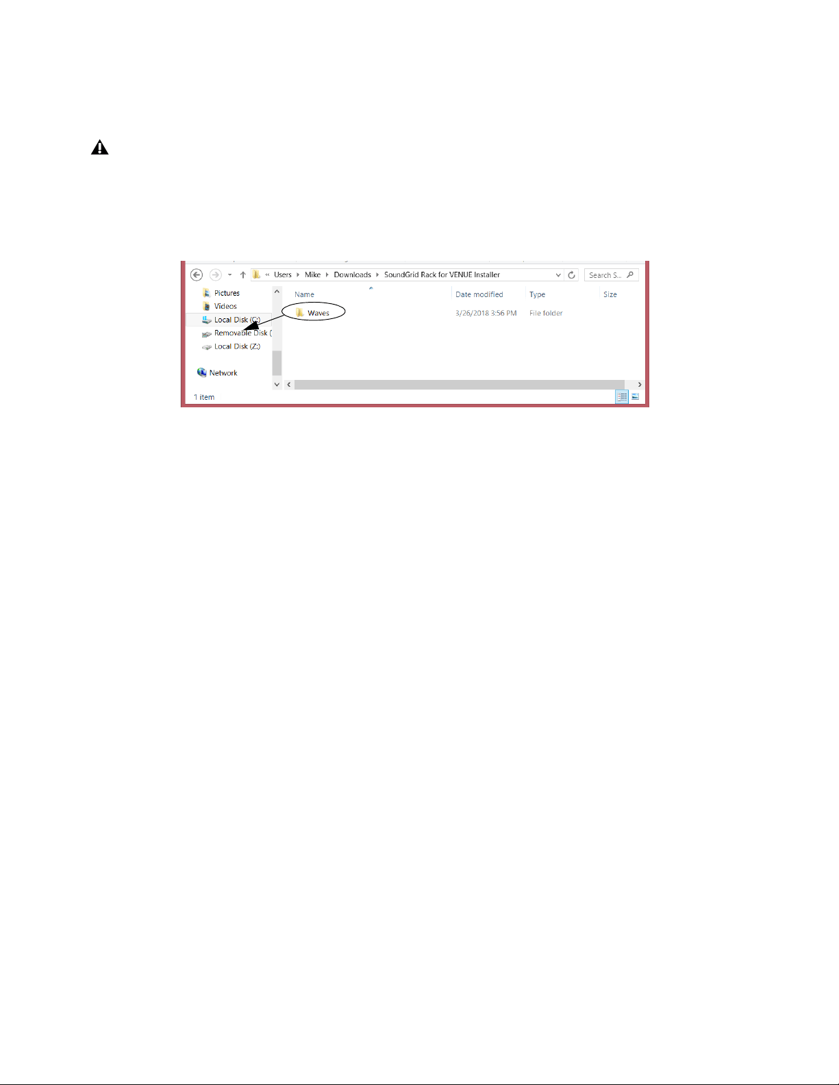
Plug-Ins 296
Downloading and Preparing the Waves Installer
To create your installer:
1 Navigate to the download page on waves.com and select SoundGrid Rack for VENUE Installer to download the .zip.
2 Insert your FAT32-formatted USB drive into an available USB port on your Windows computer.
3 Extract the download and place the resulting Waves folder on the root level of your USB drive.
Transferring Licenses
Licenses can be transferred to and stored on either a USB drive, the console, or distributed across both. At minimum, the SoundGrid
Rack for VENUE license must be present on your system to run Waves. In addition:
• Transfer licenses to your USB drive if you want your licenses, including SoundGrid Rack for VENUE, to remain mobile. Stor-
ing licenses on a USB drive also means they will not need to be re-installed onto the S6L system after performing a VENUE
System Restore.
• If your system is going to be used in a festival or similar multi-operator setting, transfer the SoundGrid Rack for VENUE li-
cense to the console to ensure it is available for all operators. Each operator can then bring their own USB drive containing
only the plug-in installers and plug-in licenses needed for their performance.
To transfer the required licenses:
1 Make sure you have registered/activated your Waves plug-in purchases.
2 Do the following:
• To transfer license to your USB drive: On your computer, open Waves Central and log into your account.
• To transfer licenses to S6L: On VENUE, go to Options > Devices, select the WSG-HD card in the Expansion Cards list,
click to display the
Settings tab in the Information section and then click Launch Waves Central. (Make sure your S6L is
connected to the internet as instructed earlier, and that you have installed Waves Central as instructed later in this guide.)
3 Select Licenses/Manage: Licenses.
4 Select Source: My License Cloud.
5 Select Products: SoundGrid Rack for VENUE as well as any plug-in licenses that you want to transfer.
6 Select Destination: your USB drive, or Console.
7 Click Send Licenses.
At the time of this writing a Windows computer is required to unzip and create installers. Macs with VMWare Fusion, Parallels and
similar are also supported. You can download the installer from a Mac but you must extract it from a Windows computer or from
a Mac running Windows on VMWare Fusion, Parallels, or similar.
Placing the folder “Waves” at the root level of a USB drive

Plug-Ins 297
Installing on S6L System
To install components onto your S6L system:
1 Make sure you have installed VENUE software version 5.7 or higher, and that your system is powered on.
2 Install Waves Central by doing the following:
• Connect the USB drive on which you built your Waves installer to an available USB port on the S6L control surface.
• Enable Config mode, navigate to Options > System, then select Update. When prompted to confirm that you want to install
Waves Central, click INSTALL.
• Follow the on-screen instructions to install Waves Central.
•Click Finish.
• When prompted to restart, click OK.
3 Install Waves plug-ins by doing the following:
• After the system restarts, enable Config mode.
• Go to Options > Devices, select the WSG-HD card in the Expansion Cards list, click to display the Settings tab in the In-
formation section and then click Launch Waves Central.
•Select Install.
• Install From: your USB key.
• Choose Products to Install: SoundGrid Rack for VENUE, as well as any plug-ins you want to install.
•Click Install. Wait while the installation completes (it takes several minutes).
• When the message Products from Package were Successfully Installed appears, click OK.
• Close Waves Central.
• Enable Config mode.
• Go to
Options > Plug-Ins, select WaveShell1SoundGridRack-AAX and click Install.
• When installation is finished, restart your S6L system.
4 Set up Inventory by doing the following:
• Enable Config mode.
• Go to Options > Devices, select the WSG-HD card in the Expansion Cards list, click to display the Settings tab in the In-
formation section and then click Show Inventory.
5 Set the Network Port to the Intel port number ending in “LM” (such as Intel(R)82579LM Gigabit Network Connection).
Options > Devices showing Settings for a WAVES-SG card selected in Expansion Card slot 6
Selecting a network port
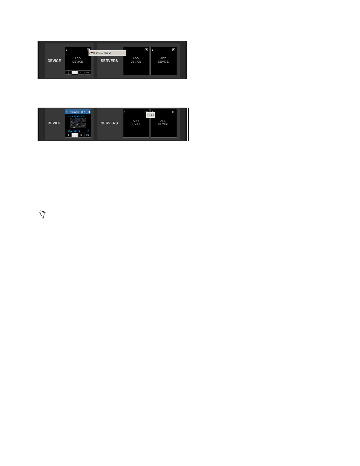
Plug-Ins 298
6 Select the Avid WSG-HD card as IO device.
7 Select your Server device.
8 Select Redundant Server if applicable.
9 If necessary, update WSG-HD firmware and Server firmware by clicking the FW icon. The FW icon indicates firmware status
as follows:
• Red means firmware is not compatible
• Blue means firmware is compatible but a new version is available.
• Grey/Black means firmware it up to date
10 Click Hide Inventory.
Completing the Installation
Complete the installation by doing the following:
1 Power cycle all SoundGrid servers.
2 Power cycle your S6L system by doing the following:
• Go to Options > System, and choose Shutdown.
• Power down the S6L control surface, E6L engine and all attached Stage I/O units. Wait for them to power down completely.
3 Power the S6L system back on.
Selecting Avid WSG-HD as an IO Device
Selecting a SoundGrid server
If any errors occur during the firmware update click RETRY until it successfully completes.
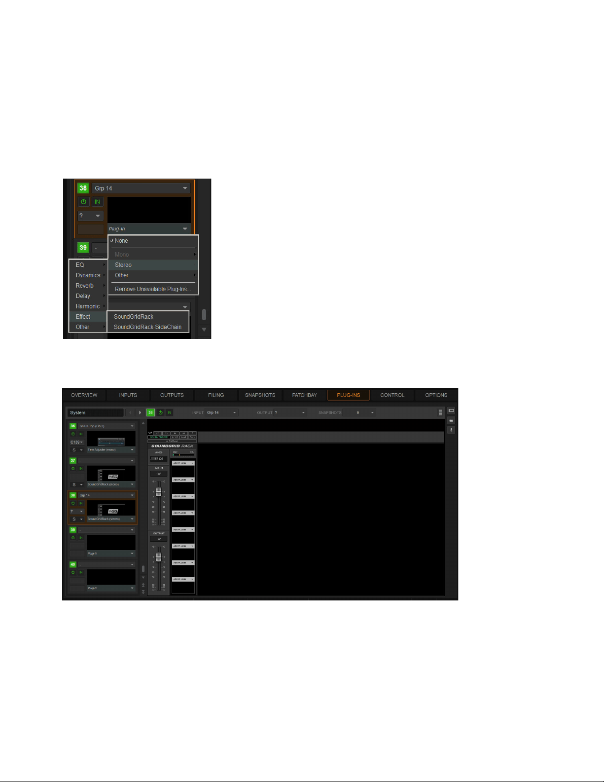
Plug-Ins 299
Using SoundGrid Plug-Ins
After making connections and configuring SoundGrid with S6L, you can start integrating SoundGrid plug-ins into your Show files.
Similarly, if you have older VENUE Show files that incorporated Waves plug-ins you should be able to load those Shows and have
your previous Waves plug-in configurations transfer automatically (as long as all the required plug-ins are available on the current
system).
To use SoundGrid plug-ins:
1 In VENUE, go to the Plug-Ins page.
2 Select SoundGridRack from the Effect sub-menu of the Plug-In selector for an available rack slot.
SoundGrid Rack appears in the Plug-in window, showing 8 available SoundGrid Rack slots.
Assigning SoundGridRack to a VENUE plug-in rack slot
A SoundGrid Rack (empty)
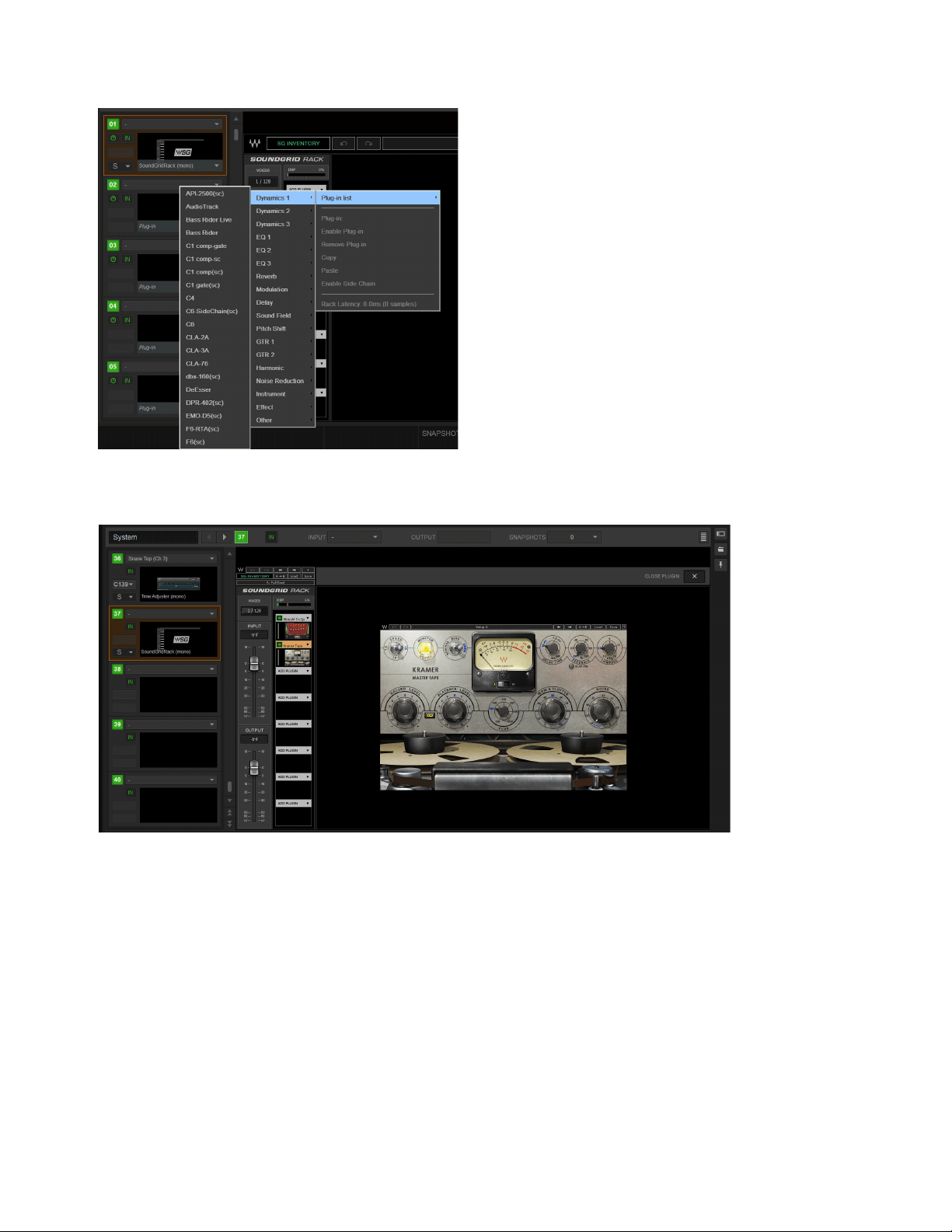
Plug-Ins 300
3 Within SoundGrid Rack, insert up to 8 plug-ins.
The selected plug-in is assigned to that slot.
4 In the VENUE rack slot for the SoundGrid Rack, configure plug-in routing as desired for use as a channel insert or bus processor.
Opening Show Files with Legacy TDM Waves Plug-Ins
When opening older Show files, any legacy TDM instances of Waves plug-ins are automatically converted to SoundGrid Rack
plug-ins. In the VENUE Plug-In rack these converted instances will appear as “SoundGrid Rack” (check the zoomed view to see
which specific plug-ins are inside that rack).
Snapshots and SoundGrid Plug-Ins
Technically each instance of SoundGrid Rack is a single plug-in. Saving plug-ins in a VENUE snapshot stores all plug-ins within
a SoundGrid Rack instance. You cannot use Snapshots to re-assign Waves plugs within SoundGrid Racks while in Show mode, you
must be in Config mode (since this could potentially require a DSP reshuffle). You can, however, use Snapshots to change plug-in
settings while in Show mode.
Inserting a Waves SoundGrid plug-in to a slot within an instance of SoundGrid Rack
SoundGrid Rack showing plug-ins in slots 1 and 2

Plug-Ins 301
Note that the following actions are not allowed via snapshots (“child plug-ins” refers to plug-ins within an instance of SoundGrid
Rack):
• Moving Waves child plug-in order
• Removing Waves child plug-ins
• Adding Waves child plug-ins
Configuring Redundant SoundGrid Servers
By connecting a compatible SoundGrid server to each of the network ports on the WSG-HD card you can run the SoundGrid serv-
ers in a redundant configuration. To minimize fail-over time during a rehearsal or performance it is recommended to pre-load the
second, redundant SoundGrid server as described below. This procedure only takes a short amount of time and helps ensure the
fastest switching possible.
To minimize fail-over time, do the following:
1 Load a Show file and/or configure the Plug-in Racks with instances of SoundGrid Rack and Waves plug-ins on the active (pri-
mary) SoundGrid server.
2 After confirming the racks are configured with all the Waves plug-ins you want, disconnect the network cable from the
WSG-HD card that is connected to the active (primary) SoundGrid server.
The second, redundant SoundGrid server begins loading the current configuration. This might take a minute or two depending
on the number of SoundGrid Racks and plug-ins in use.
After the redundant SoundGrid server has loaded the configuration, reconnect the first, primary server.

Events 302
Events
An event consists of one or more triggers, which are configured to cause one or more actions to occur.
Events can be very simple, such as the press of a Function switch enabling a Mute Group, or the press of a connected footswitch
triggering a Recall Next Snapshot. These are examples of a single specific trigger (a press of a specific Function switch or the press
of a footswitch) causing a single action (enabling a Mute Group or Recall Next Snapshot).
Events can also be quite complex and involve multiple triggers and actions. For example, a single event can be defined so that mov-
ing a specific fader above and/or below a certain level sends a General Purpose output, and recalls a specific snapshot and mutes
one or more channels. Multiple triggers can be considered conditionally using the available logic operators AND, OR, and XOR.
Events can be defined to operate on specific channels, or to operate globally using the “Any...” Triggers and “Triggered....” Ac-
tions.
Any...Triggers
Many sub-menus in the Triggers menu include choices for Any Aux, Any Group, Any Matrix, Any Mains, and Any
VCA (when relevant). Any Strip refers to any input, output, or bus. Any Channel refers to Input Channels only. These let you define
triggers that fire whenever the defined criteria is met on any strip, channel type, or channel.
Triggered Strip Actions
Similarly, many sub-menus in the Actions menu provide the choice for Triggered Strip. Choosing Trig-
gered Strip creates an action that is applied to the input, output, or bus on whichever strip triggered the Event.
Each event can have between 0 and 8 triggers, and each event can have between 0 and 8 actions. Up to 999 events can be created.
The Event list is easy to configure, and pre-configured events are provided to change View Mode on the external screen.
Ter minology
Event
A user-defined combination of one or more triggers and one or more actions. Each event serves as a type of software “macro”
in which you establish a cause-and-effect relationship between one or more triggers and their results (actions).
Trigger
A conditional check used to fire an event, such as the press of a Function switch. Other available Triggers include fader
above/below, meter values, time of day, and MIDI.
Action
A command, mode or other response resulting from an event being triggered.
Control (Continuous)
A variable control such as a fader or knob.
Control (Switch)
A two-state control such as most switches on the control surface.
System Values
Variables such as Fader Above or Below, and system response values such as channel meters and dynamics gain
reduction meters.
GPI
General Purpose Interface, also known as a logic interface. The S6L control surface provides 2 GPI inputs and 2 GPI outputs.
Open
GPI input or GPI output is floating, or at its reference voltage. Or, a Gate is open.
Closed
GPI input or GPI output is closed. Or, a Gate is closed.
Footswitch
Footswitch ports are functionally identical to GPI inputs and share all of the same properties and behaviors.
Properties
The criteria that define triggers and actions. Properties can be edited for many, but not all types of triggers and actions.
Important Information about Snapshots and Events
Because events can trigger snapshot recalls, and because snapshot recalls can trigger other events, it is possible to create logic
“feedback loops.” For more information, see Avoid Feedback Loops.
For more information on the default events and other examples, see
Default Settings, Templates and Examples.
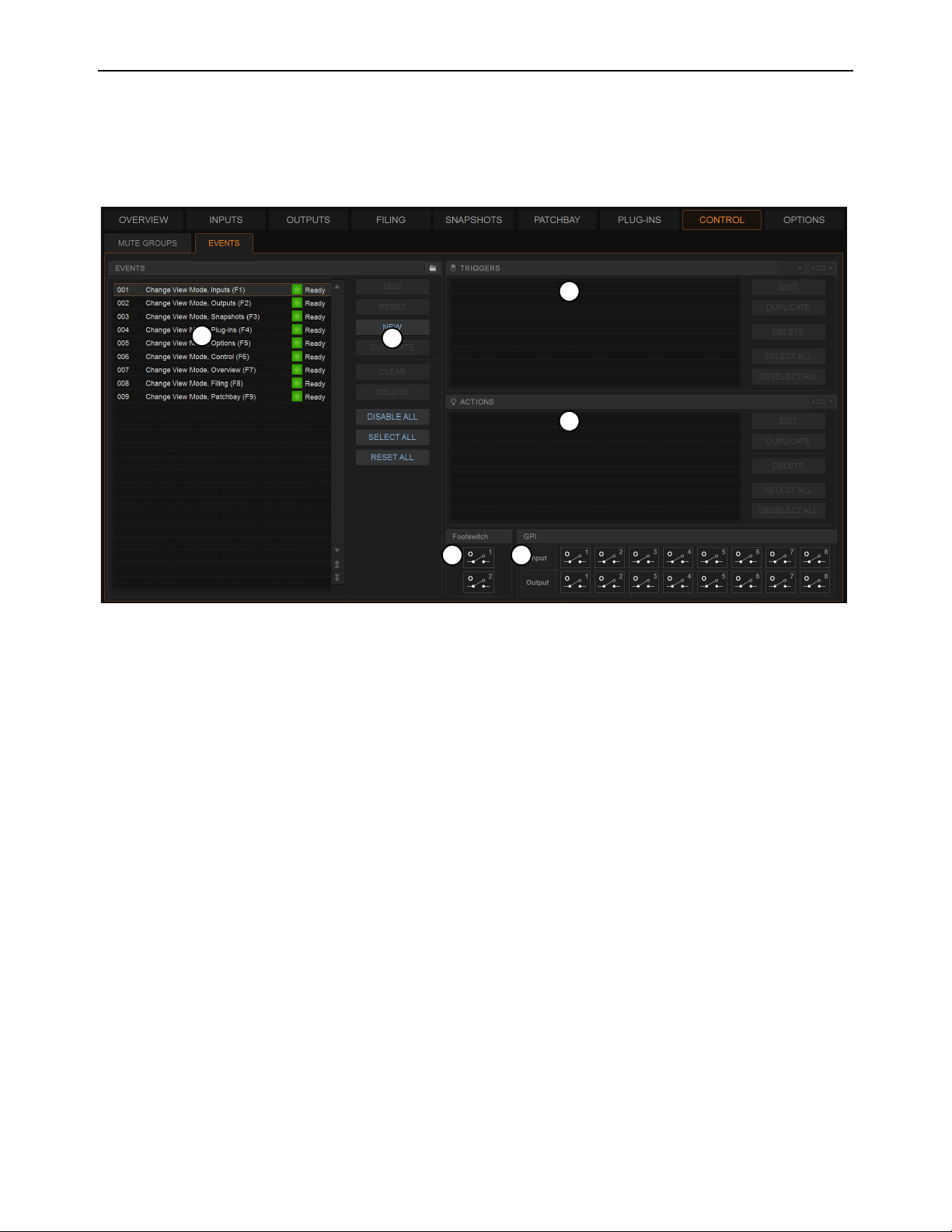
Events 303
The Events Tab
The Events tab of the Control page is the working area of the Event list system. Events are defined and managed using the Event
list, along with the Triggers and Actions lists. The lists and commands available in these sections create a powerful, user-program-
mable environment. Footswitch and GPI status display are also shown on the Events tab. You can create and load Events Presets,
and import events into the current Show file.
1 –
Event List
2 – Event List Commands
3 – Triggers
4 – Actions
5 – Footswitch Status Display
6 –
GPI I/O Status Display
Figure 3. Events window (Control > Events)
1
2
3
4
5 6
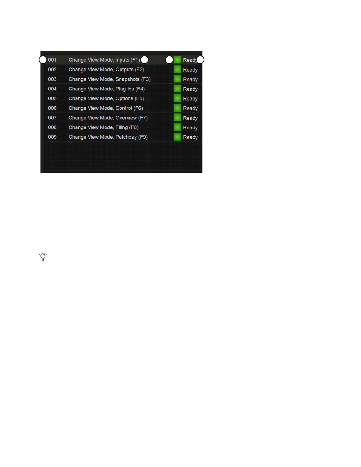
Events 304
Event List
Each event is shown in its own row within the Event list. The list can be scrolled vertically when necessary.
The Event list contains the following elements:
1 – Event Number
Each event has an associated three digit sequence number, 001 through 999. Events are automatically re-numbered if items are
moved, added or removed.
2 – Event Name
Events can be given custom names, up to a maximum length of 31 characters.
3 – Event Enable Icon
Events can be enabled or disabled individually by selecting the green Enable indicator to toggle its status. All events can be disabled
(suspended) and enabled using the global Disable All button.
4 – Event Status
The Event Status column shows Active (currently in effect), Ready, Disabled (indicated by a dash) or Test state. For more infor-
mation on the Status column, see
Resetting Events.
Event List Commands
You can test, reset, create, duplicate, clear or delete events in the list. These commands apply to any selected (highlighted) events
in the list, and can be performed using the buttons or by touching-and-holding (right-clicking) list items. Multiple events can be se-
lected to test, reset, duplicate, clear or delete them, but only one new event can be created at one time.
You can also utilize Events Presets.
Event list items, commands and displays
Although more than 31 characters can be entered, limit your Event names to 31 characters or less.
1 2 3 4
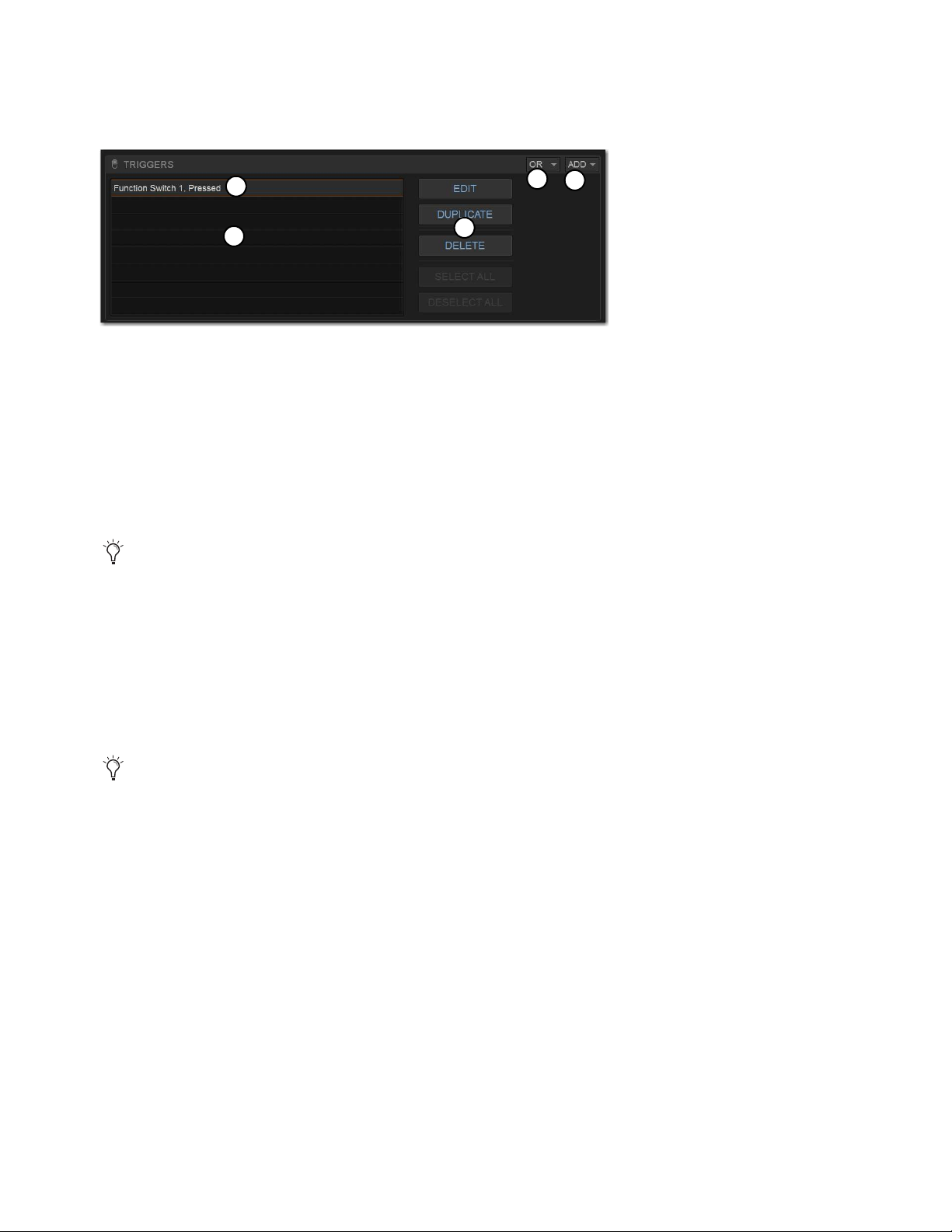
Events 305
Triggers
The Triggers list shows the name and properties of each trigger defined for the currently selected event, as well as commands to
create and manage triggers.
1 – Triggers List
Each event can have up to eight triggers in the list. Triggers are shown in rows in the Triggers list. Touch-and-hold (right-click)
commands to select, edit, duplicate and delete triggers.
2 – Type and Properties
Each row in the Triggers list shows the selected trigger type. Some types of triggers have editable properties such as a dB level on
a specific channel, or open/closed state of a footswitch or GPI input. Choices vary depending on the trigger type, and not all triggers
have editable properties.
3 – Add
The Add pop-up menu lets you create new triggers. Triggers are organized in the menu according to the type of input signal that
initiates (or triggers) the event. Types of triggers include channel functions, system values, footswitch/GPI inputs, snapshot recall,
and other functions such as talkback.
4 – Logical Operators
Multiple triggers can be considered conditionally by applying a logical operator (AND, OR, XOR) to their properties.
5 – Triggers List Command Buttons
You can edit, reset, duplicate, delete, and select/deselect all triggers in the list. These commands can be performed using the
on-screen buttons or by touching-and-holding (right-clicking) list items. Multiple triggers can be selected for editing, but only one
new trigger can be created at one time.
Triggers list
Triggers assigned to Function switches become available in the VENUE Function Pad app. Each Show file can store up to
128 Function switch assignments.
Triggers and actions which are unavailable due to hardware configuration or other factors are shown as italicized in the
Trigger (and Action) Add menus.
1
3
4
2
5
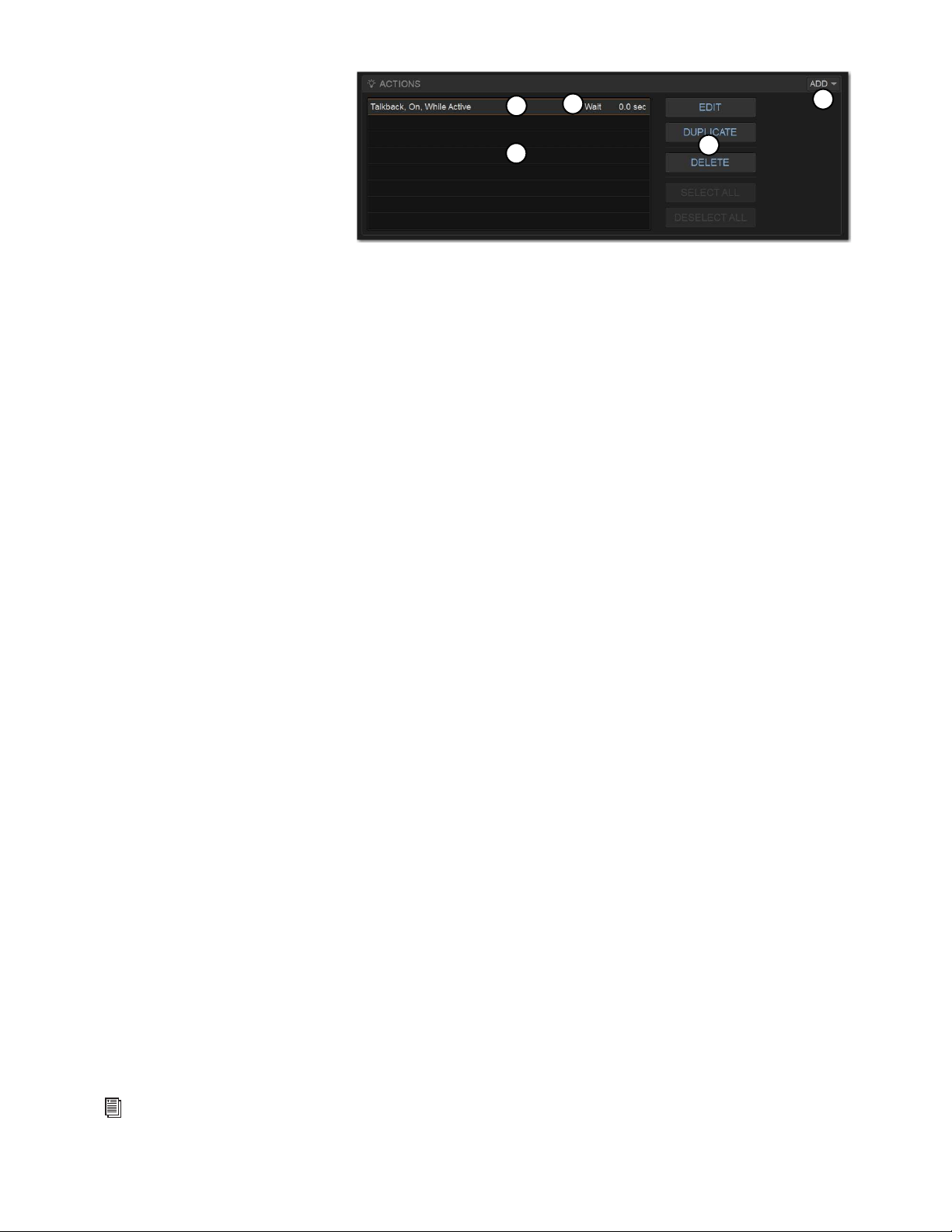
Events 306
Actions
The Actions list shows the actions de-
fined in the currently selected event, as
well as commands to create and manage
actions.
1 – Actions List
Each event can have up to eight actions in
the Actions list. All actions occur when
the event is fired. Touch-and-hold (right-click) commands let you select, edit, duplicate and delete actions.
2 – Type and Properties
Each row in the Actions list shows the selected action type. Some actions have editable state and behavior settings. Some actions
have editable properties such as on/off or toggle state for Control (Switch) actions or open/closed state of a GPI output. Some con-
tinuous control actions have editable values (Relative or Absolute) with cross-fade options. Choices vary depending on the action
type, and not all actions have editable properties.
3 – Add
The Add pop-up menu lets you create new actions. Actions are organized in the menu according to the type of function they affect,
such as channel functions, snapshots, GPI Output and Tap Tempo.
4 – Wait
All actions have a Wait (delay) setting that can be applied to the action.
5 – Triggers List Command Buttons
You can edit, reset, duplicate, delete, and select/deselect all actions in the list. These commands can be performed using the
on-screen buttons or by touching-and-holding (right-clicking) list items. Multiple actions can be selected for editing, but only one
new action can be created at one time.
Footswitch Status Display
The Footswitch status display shows the current open or closed status of Footswitches connected to the Footswitch connectors on
the S6L control surface. Default state for both Footswitches is closed. A Footswitch can be added as a trigger for an action in an
event. Example uses of a Footswitch trigger includes Tap Tempo and snapshot recall. The Footswitch can be named.
GPI I/O Status Display
The GPI port on the back of the S6L control surface can be used to trigger events in VENUE from outboard equipment (GPI input),
or can be used to send messages to trigger outboard equipment to perform one or more actions (GPI output).
The GPI status display shows the current open or closed status of the two GPI inputs and two GPI outputs. Each input and output
can be named.
GPI Inputs
GPI inputs can be added as a trigger for an action in an event. Example uses of GPI inputs include remote snapshot recall
and remote channel muting from an external control system or custom control panel.
GPI Outputs
GPI outputs can be added as an action triggered by a selected trigger. Example uses of GPI output include the follow-
ing:
• Sending a pulse to trigger samplers and playback devices
• Indicating when a microphone or channel is live by lighting an On Air or “tally” light
• Flashing or turning on a light when the system is in a particular mode (such as Solo In Place)
• Integrating with power sequencing devices for automated system turn-on
For GPI port wiring specifications, see
GPI Port Reference.
1
3
2
4
5
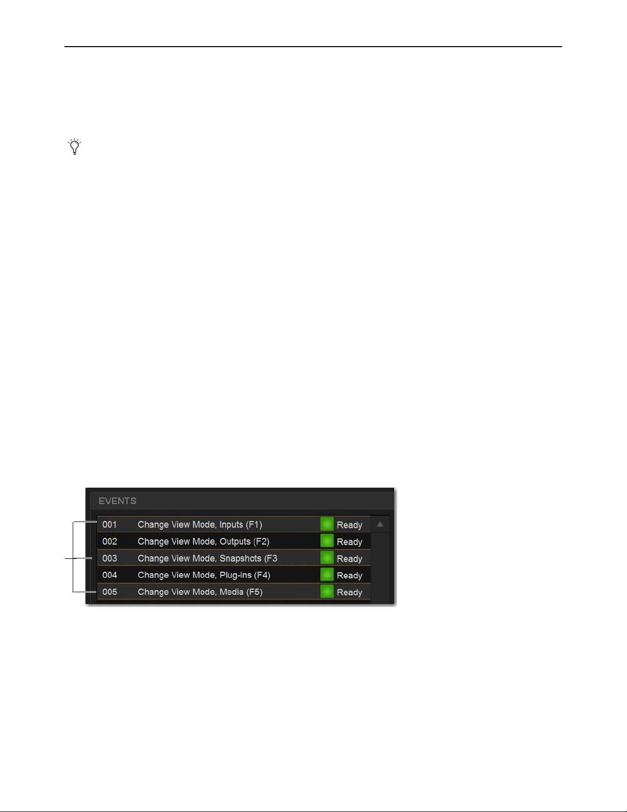
Events 307
Creating Events
The basic steps to create an event include the following:
• Add a new event in the Event list (see Adding an Event).
• Add and configure triggers for the event (see Adding Triggers to an Event).
• Add and configure actions for the event (see Adding Actions to an Event).
Adding an Event
To add a new event to the Event list:
1 Go to the Control page and select the Events tab.
2 Do any of the following:
• To create an empty, untitled new event, select the New Event Command button.
– or –
• To create a copy of a pre-existing event, select one or more events in the Event list and select the Duplicate button.
3 Double-tap the event name in the list, and enter a name for the event.
Selecting Events
Event list items can be selected, renamed, duplicated, deleted, cleared, enabled or disabled, tested and reset. Selected events are
highlighted in the Event list.
To select one or more events, do any of the following:
• To select a single event, select its row in the Event list.
• To select all events, select the Select All button in the Event Commands section.
• To select multiple consecutive events, select the first desired event and then Shift-touch the last desired event. All events in
between are selected.
• To select multiple non-consecutive events, or to de-select an individual event, Ctrl-touch its row in the Event list.
To deselect or ore more events:
Touch-and-hold (right-click) anywhere in the Event list and choose Deselect All.
Several pre-defined (default) events are available immediately; others
Default Events are available among the Demo Shows
installed with the system software. You can load these defaults using Events Preset, and import individual events into the current
Show file.
Multiple events selected in the Event list

Events 308
Moving Events
Selected events can be dragged and dropped to new locations in the list. You can also manually edit the event number to re-se-
quence items.
To move one or more events:
1 Select one or more events in the Event list.
2 Touch any selected event and drag them to a new location in the list. As you move events, a white line appears indicating the des-
tination.
3 Release your finger to drop the events at the desired location in the Event list. When moving multiple events, moved events will
be adjacent regardless of their original locations relative to each other (whether adjacent or non-adjacent). events will be renum-
bered as necessary according to the new sequence of events.
To manually edit an event number:
Double-tap the Event Number and enter a new three digit number to resequence the list accordingly.
Managing Events in the Event List
Once created, events in the list can be managed using on-screen buttons and touch-and-hold (right-click) commands to rename, du-
plicate, delete, clear, enable or disable them.
Renaming an Event
To rename an event:
1 Double-tap the event name in the list.
– or –
2 Touch-and-hold the event name, the select Rename from the menu.
3 Enter a new name.
4 Press Enter to confirm the new name.
Event Name and Function Keys
Function keys are automatically named with the Event name when defined as a Trigger for one
or more Events. The Event / Function key name is displayed in the right bank of Soft Keys on the MTM when Function keys are
shown. When a Function key is assigned to multiple Events, the Function key name displayed on-screen is the name of the Event
with the lowest number in the Events List.
Duplicating an Event
Duplicating an event can simplify Event list configuration when multiple, similar events need to be created, each with slightly dif-
ferent properties.
To duplicate an event:
1 Select one or more events in the Event list.
2 Select the Duplicate Event Command button on-screen. Or, tap-and-hold (right-click) a selected event and choose Duplicate.
You can also use the Test and Reset commands to manually audition events for development and diagnostics. For more infor-
mation, see
Testing Events
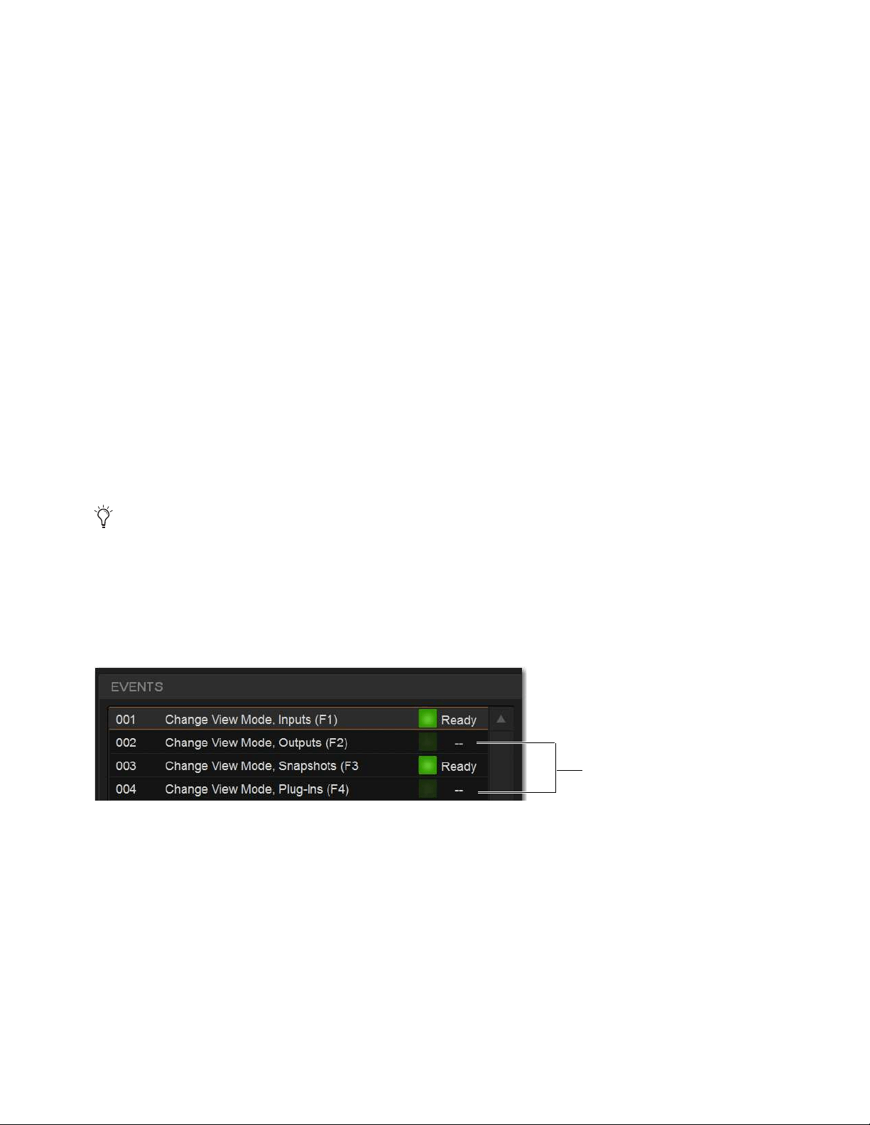
Events 309
Deleting and Clearing an Event
Deleting an event removes it permanently from the Event list. Clearing an event leaves the named event in the Event list but clears
all associated triggers and actions.
To delete an event:
1 Select one or more events in the Event list.
2 Select the Delete Event Command button on-screen. Or, touch-and-hold (right-click) a selected event and choose Duplicate.
3 Select Delete in the Confirm Event Operation dialog to delete the event. Or select Cancel to cancel the operation.
To clear an event:
1 Select one or more events in the Event list.
2 Select the Clear Event Command button on-screen. Or, touch-and-hold (right-click) a selected event and choose Clear.
3 Select Clear in the Confirm Event Operation dialog to clear the event. Or select Cancel to cancel the operation.
Enabling and Disabling Events
Events can be disabled to suspend their operation. An event can be selected and edited while it is disabled. You can toggle the en-
abled state of one or more events in the list by selecting the on-screen Enable icons in the Event list, or you can disable the Event
list globally by selecting the master event
Disable All button.
Disabling an event stops all timers (X-Fade and Wait/delay properties) associated with that event, preventing any pending (de-
layed) actions configured for While Active behavior from occurring. Disabling an active event does not automatically de-activate
any associated actions configured for While Active behavior. Use the Reset command instead (see
Resetting Events).
To toggle the enable/disable status of an event in the list:
1 Select one or more events in the Event list.
2 Select the Event Enable icon for the selected event to toggle its state. Or, touch-and-hold (right-click) an item and choose Enable
or Disable as appropriate. When the Enable icon lights (green) and “Ready” is shown in the Event Status column, the event is
enabled. When the icon is unlit and a dash is shown the event is disabled.
To disable all events:
1 Select the Disable All Events Command button. The Disable All button lights, and all items in the Event list show a dash in the
Status column.
2 To re-enable all events select the Disable All button again.
All events are prevented from firing when the global Disable function is in effect. However, active events are not de-activated.
Use Reset or Reset All for this (see
Resetting Events). Individual event enable/disable status is preserved (events retain the cur-
rent state of their Enable icons) and can be modified when globally disabling and enabling events using the master Disable but-
ton.
Disabling an event can be a useful troubleshooting tool, such as when an event has caused an action/trigger feedback loop
and must be edited before being re-enabled.
Disabled events

Events 310
Events Presets
You can save and load Events Presets files to import, export, and transfer Events. You can also create your own Events Preset fold-
ers to organize Events Preset files. Preset folders and files can be transferred using the Filing page. A Factory Preset file is installed
automatically, letting you restore Events definitions created at the factory.
To create a custom Presets folder:
1 Go to the Filing page and select the Transfer tab.
2 Select the Preset Folders icon.
3 Select the New button at the left of the screen.
4 Do one of the following:
• To leave the folder at its default name, press Enter.
• Type a new name and press Enter.
To save a Preset:
1 Go to Control > Events, and configure the Events list as desired.
2 On the Events tab, select the Presets icon.
3 In the Presets window, select New.
4 Enter a custom name for the Preset.
To load a saved Events Presets file:
1 Make sure the presets are already transferred and available on the current system.
2 Go to Control > Events.
3 Select the Presets icon.
4 Select a preset name in the Presets list to preview it. With the Presets list displayed, do any of the following:
• To scroll through the list, press Up or Down arrow keys on your computer keyboard.
• To load a preset and close the Presets list, double-tap a name in the Presets list.
•Select
Cancel to close the Presets list without changing settings.
To rename, duplicate, delete, or overwrite a Presets file:
1 Go to Control > Events.
2 Select the Presets icon.
3 Right-click on the item and choose Rename, Duplicate, Delete, or Overwrite.
The factory (Default) Events Presets contain definitions for F (Function) keys 1-9 to jump to different pages on the external screen.
Events Presets icon (Control > Events)
Selecting Events Presets replaces all events currently in the list. To selectively add events to the list, see
Import Snapshots and
Events.

Events 311
To transfer Events Presets:
1 Go to the Filing page and select the Transfer tab.
2 Connect a USB flash drive to the S6L control surface. The device appears above the right column.
3 Select the Events block.
4 Do one of the following to select the items to transfer:
• In the left column, select the items you want to transfer to the portable storage device.
– or –
• In the right column, select the items you want to transfer from the portable storage device to your system.
Be sure to select the desired folder for the destination/source device. For more information on creating Presets folders and nav-
igating the Filing page, see the
VENUE S6L System Guide.pdf.
5 Select the Transfer button.
Creating Triggers
Each Event can have up to eight triggers. You create new triggers by selecting them from the Add
pop-up menu.
Once added, you can edit triggers and their properties to customize them.
Adding Triggers to an Event
To add a trigger:
1 Select an Event in the Event list, or create a new one. (For details, see
Selecting Events, and
Creating Events.)
2 Select the ADD button in the Triggers list, and then choose the trigger type from the pop-up menu
or any of its sub-menus.
The chosen trigger type is added to the Trigger list for the currently selected Event, with its default
properties. The figure below shows an example trigger based on Function Switch 1.
Events selected in Filing > Transfer
Trigger added to Triggers list
For a list of available trigger types, see
Trigger Types. For examples of different trigger types in use, see Examples.
Triggers menu

Events 312
Editing Trigger Type and Properties
To edit the trigger and its properties:
1 Double-tap the trigger row in the list. Or touch-and-hold (right-click) the action item and choose Edit.
2 Choose a new Trigger Type, or edit any of the available properties in the row for that trigger. Properties vary depending on the
type of trigger selected (not all trigger types have editable properties).
3 Touch anywhere else to exit.
Logical Operators for Triggers
An individual trigger is considered to be “true” when the function described by its type and properties takes place, such as while a
footswitch is actually pressed, or a fader is raised above its trigger threshold.
A trigger is considered to be “false” (or, not occurring) whenever its function and properties are not met, such as when a footswitch
is not being pressed, or while a fader remains below its assigned trigger threshold.
When an Event includes multiple triggers, a logical operator (OR, AND, XOR) must be chosen from the Operators pop-up menu.
(The default Operator is OR.)
The logical operator has no effect when the Triggers list includes only one item.
To choose a logical operator for the current Event:
1 Select the desired Event to display its assigned triggers.
2 Select the Operators pop-up menu (by default, this pop-up menu displays “OR”) and choose AND, OR, or XOR.
Only one logical operator is permitted per event, and this operator applies to all triggers within the event. It is not possible to use
a mix of logical operators within an event. For examples of logical operator behaviors, see
Examples of Logical Operators.
Managing Triggers in the Triggers List
Triggers in the list can be selected, edited, duplicated and deleted.
Selecting Triggers
Triggers can be selected using the same methods as used when selecting items in the Event list. For more information, see Select-
ing Events.
Editing Triggers
To edit a trigger:
1 Select the item in the Triggers list so it is highlighted, then select the Edit button.
– or –
• Touch-and-hold the desired trigger, then select Edit from the menu.
When the chosen item is a switch or other two-state control, selectors for Type (1 in the figure below) and State (2 in the figure
below) are displayed in the trigger row.
The Trigger List Edit button
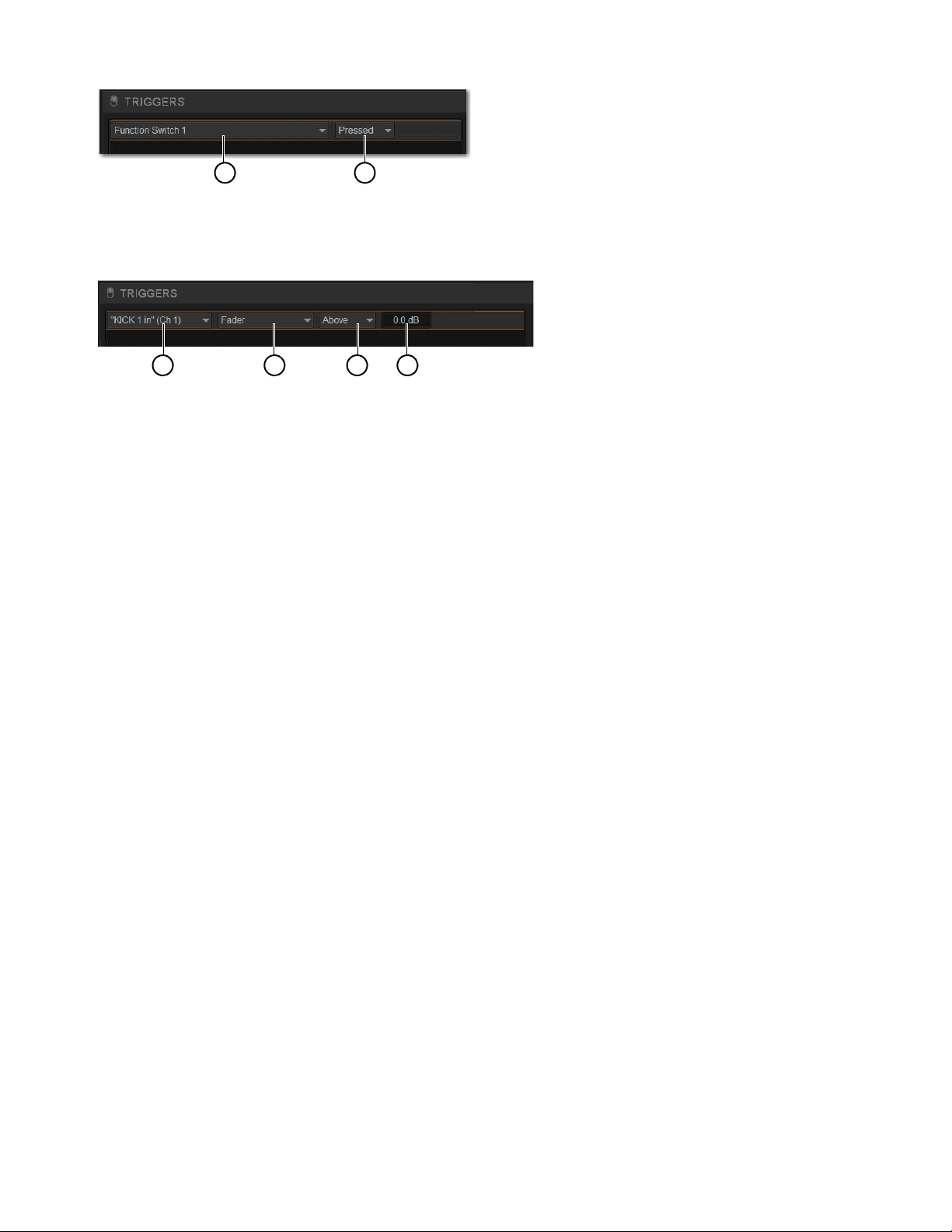
Events 313
When the chosen item is a continuous control or value, selectors for Type (1 in the figure below), Control (2), Above/Below (3,
for Fader, Meter, and certain other Types), and editable field for Value (4 in the figure below) are displayed.
2 Do any of the following:
• To change the trigger type (such as choosing a completely different control, choosing a different channel, or changing a trigger
to an “Any...” type), select the
Type pop-up menu and make a new selection from the Type menu.
• For switches, buttons and other two-state functions, select the State pop-up menu and make a selection. Choices for State vary
as appropriate for the trigger type, and will include Closed or Open, On or Off, and Pressed or Released.
• For continuous controls, use the
Above/Below pop-up menu (as available) to define the trigger. To change the specific trigger
control or value for the current type (such as to change Fader to Aux level for the current channel), select the Control pop-up
menu and make a new selection.
• For
Fader Above/Below triggers (such as for faders), select the currently displayed dB value to highlight it, then type in a new
value.
• For System Values (such as Meter Above/Below), set a dB value, Hold time and Release time.
3 To confirm your changes, press Enter or select anywhere else in the Events window.
Duplicating Triggers
To duplicate a trigger:
1 Select the item in the Triggers list so it is highlighted, then select the Duplicate button.
– or –
• Touch-and-hold the desired trigger, the select Duplicate from the menu.
Deleting Triggers
To delete a trigger:
1 Select one or more items in the Triggers list so it is highlighted, then select the Duplicate button.
– or –
2 Touch-and-hold the desired trigger, the select Duplicate from the menu.
Channel X / Y Function Switches
In their default configuration, the X and Y switches in each channel strip toggle the corresponding Expander/Gate and Compres-
sor/Limiter on/off, respectively. You can reconfigure these switches to instead become available Triggers and Actions.
To enable channel X and Y switches for use as Triggers:
In the Fader Configuration section of the Options > Interaction tab, enable the Use X/Y as Event Triggers/Actions option.
Properties for a switch trigger
Properties for a continuous control trigger
1 2
1 2 3 4
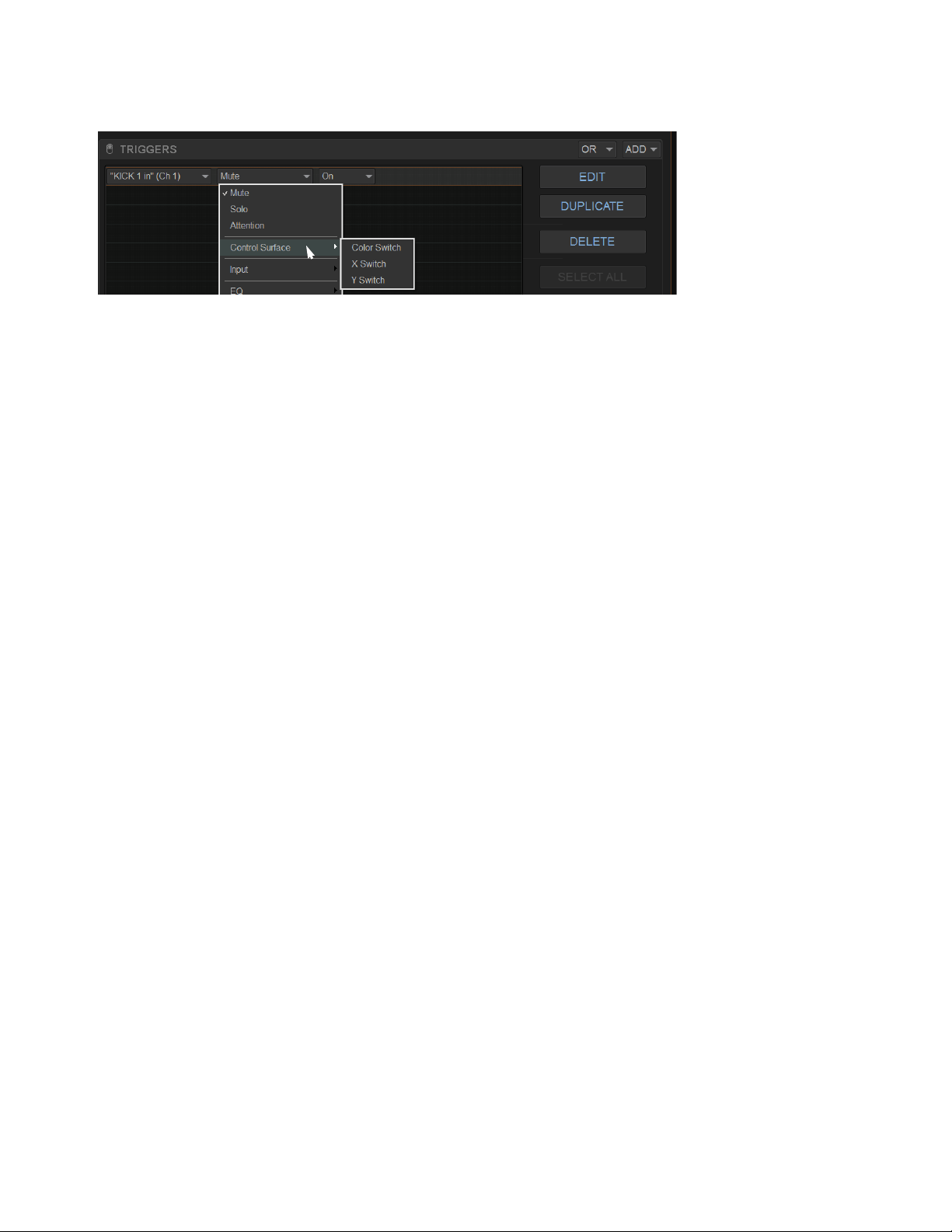
Events 314
When enabled for use as Triggers and Actions:
• X and Y switches become available in the Switch (Type) list in the Trigger properties, in the Control Surface sub-menu.
• X and Y switch LED state (Light and Flash) become available in the Switch (Type) list in the Action properties, in the Control
Surface sub-menu.
•
X and Y switches no longer toggle their corresponding dynamics processor on/off, even if they are not yet included in the defi-
nition of any specific Event.
System Values as Triggers
Events can be triggered by meter above/below values, and by Gate open/closed state.
Editable properties for System Value Triggers include the following:
Hold
How long the threshold must be met or exceeded before the Trigger becomes active.
Release
The length of time the Trigger stays active once the value has crossed the threshold again.
X and Y in the Switch sub-menu (requires the Use X/Y as Event Triggers/Actions setting is enabled in Options > Interaction)

Events 315
Creating Actions
Each event can have up to eight actions. You create new actions by selecting them from the Add
pop-up menu.
Once added, you can customize actions by editing their properties, as available.
Adding Actions to an Event
To add an action:
1 Select an event, or create a new one.
2 Select the ADD button in the Action list, and then choose an action type from the pop-up menu
(shown at right).
The chosen action type, with its default settings, is added to the action list area. The figure below
shows an example action has been added to control Talkback.
Editing an Action Type and Properties
To edit an action:
1 Select an item in the Actions list so it is highlighted, then select the Edit button.
– or –
1 Touch-and-hold the desired trigger, the select Edit from the menu.
2 Select the displayed action Type and make a new selection.
Action State
To edit an action State for switches, buttons and other two-state functions:
Select the State pop-up menu and make a selection. Choices for State vary as appropriate for the trigger type, and will include
Closed or Open, On or Off, and Toggle.
Action added to Action list
For a list of available actions, see
Action Types. For examples of different types of actions in use,
see Examples.
Action properties for a switch (two-state) control
Actions menu
Action Type State Behavior Wait
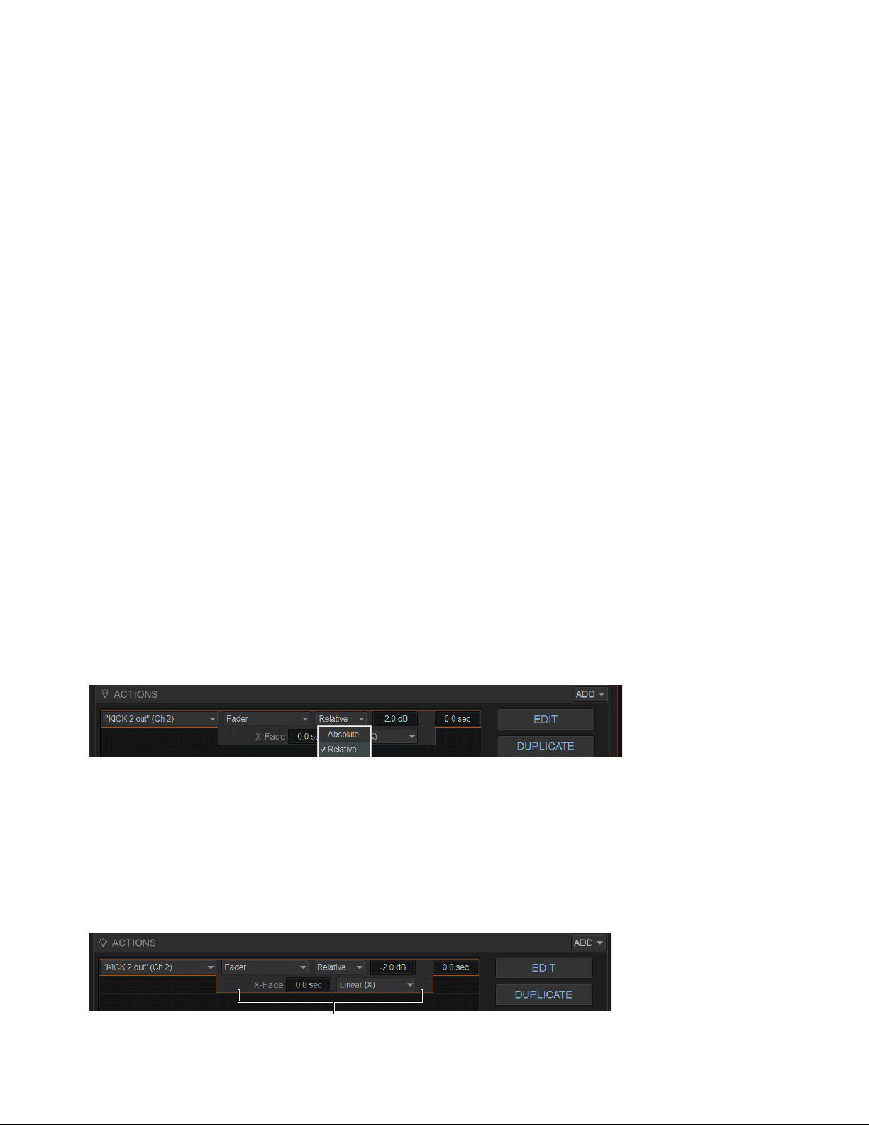
Events 316
Action Behavior
To edit action behavior for switches, buttons, and other two-state functions:
Select the Behavior pop-up menu and choose Latch or While Active, as appropriate:
Latch
Fixes the behavior in its defined state (such as open or closed) until unlatched by another event or operation.
While Active
Latches the behavior in its defined state as long the associated trigger is in effect (active, or “true”), such as unmuting
a channel only while a footswitch is pressed and held.
Pulse and Duration (GPI Output only)
Produces a single-shot pulse output. Duration range is 0.1 second (100 ms) to 1.0 second,
in 0.1 second increments. The default duration is 0.3 seconds (300 ms).
To configure GPI output pulse and duration for an action:
1 Double-tap the action to edit it.
2 Select the Behavior pop-up and choose Pulse.
3 Enter a value for Pulse Duration.
4 To confirm you changes, press Enter or select anywhere else in the Events window.
Action Wait
All actions let you specify a Wait time of up to 100 seconds for the action to wait before firing. This can be useful for synchronizing
the timing of multiple external devices, or to build timed sequences of actions.
To configure action Wait (Delay):
1 Double-tap the action to edit it.
2 Select the Wait value box to highlight it and enter the desired time.
Absolute and Relative Continuous Control Actions
When defining an Action to raise or lower a continuous control (such as channel volume or Aux Send level) you can choose to ap-
ply an Absolute or Relative change, with or without a cross-fade.
Absolute
Sets the parameter to an explicit value, such as setting a fader to exactly +3 dB.
Relative
Adjusts the parameter by a defined value relative to its current position. For example, lowering a fader by - 2 dB.
X-Fade Continuous Controls
Control (Continuous) Actions can have a cross-fade included in their definition, with variable shape.
To include a cross-fade in an Action:
1 In the Actions list, select the specific Action and click Edit (or double-click the Action).
2 Enter a value for X-Fade, and if desired choose an available shape for the cross-fade (such as Linear, Sine, X^2).
Defining a Relative action
Cross-fade (X-Fade) and Shape
Events 317
Selecting Actions
Actions can be selected using the same methods as used when selecting items in the Event list. For more information, see Selecting
Events.
Managing Actions in the Actions List
Actions can be moved, renamed, duplicated, and deleted, just as you can with triggers. For instructions on managing items in the
Actions list, follow the instructions for triggers in Managing Triggers in the Triggers List.
Testing Events
An event can be manually triggered to test it, regardless of its current status or enabled/disabled state. Use this feature to verify ac-
tion properties and confirm proper operation of devices connected to GPI output ports. When an event is in Test mode, it is effec-
tively considered true until the event is manually reset. An event in test can be re-tested at any time by again pressing the Test but-
ton. You do not have to reset in-test events to re-test them. Incoming triggers are ignored when events are in Test mode. For
example, if a footswitch event is being tested and you accidentally hit the footswitch at some point during the test, the event does
not revert to Active the moment Test is canceled. Events always return to their ready state following a Reset. Events won’t re-fire
until the trigger logic re-asserts itself as true.
To test events:
1 Select one or more events in the Event list, then select the Test button.
2 When you're satisfied the event is behaving correctly, select the Reset button.
Resetting Events
You can use the Reset command to quickly reset Active or in-Test events to “ready.” You can also use the Reset All command to
immediately reset all events in the list. The current status of each event is shown in the Status column in the Event list:
To reset an event:
Select one or more events in the Event list (see
Selecting Events), then select the Reset Event Command button.
To reset all events:
Select the Reset All button.
When events are reset, the following rules are applied:
Latching or pulsed actions which have already occurred are unaffected. For example, reset does not unlatch a previously latched
function.
All action delay timers (Wait) are immediately canceled.
Actions configured for While Active behavior are immediately canceled.
Events will not occur until the trigger logic again evaluates as true.
For example, let’s say you have an event configured to close a GPI Output whenever Channel 3 is muted (its behavior property is
While Active). Resetting the event opens the GPI Output, even though Channel 3 might still be muted. The event will re-trigger the
next time the channel goes from an unmuted state to a muted state.
Status Description
Active Event is currently true (triggered)
Ready Event is currently false (not triggered)
Disabled Event is disabled and can not be triggered
Test Event has been manually triggered

Events 318
Snapshots and Events
Events can include snapshot functions among their triggers and actions.
Snapshots as Triggers
Events can be triggered by the following snapshot functions:
• Recall of specific snapshots
• Enabling of Snapshot modes (Preview, Update and Edit)
Snapshots as Actions
Event actions can include the following snapshot functions:
• Recall of a specific snapshot
• Recall the previous, next or selected snapshot.
• Initiate Store to Selected Snapshot commands (overwriting and updating snapshots)
• Enable different Snapshot modes (Preview, Update and Edit)
Snapshot Modes and Event Status
While in Update or Edit modes, events-driven snapshot recall is suspended.
While in Preview mode, triggers that occur in the online state of the system are executed, including MTC-driven recall of snap-
shots. Triggers caused by changes to the offline (Preview) controls are ignored and do not cause events to occur.
Avoid Feedback Loops
Because events can both affect and be affected by snapshots, it is possible for events to cause “feedback loops.”
Be especially careful when Recall Previous or Next snapshot triggers and actions are combined with events that recall a specific
snapshot, as shown in the following diagram.
Diagram illustrating potential logic feedback loop between events and snapshots
The global event Disable All and Reset All buttons can serve as “panic” buttons to temporarily suspend and/or reset all events,
giving you a chance to diagnose the source of any problems. For more information, see
Resetting Events.
Event 011
Event 414
Trigger:
Action
Recall of Snapshot 003
:
Recall Next Snapshot
Recall of Snapshot 004
Trigger:
Action:
Recall Previous Snapshot
Result: Snapshot 004
Result: Snapshot 003 is recalled
Snapshot 003 is recalled (manually, MTC, other)
is recalled
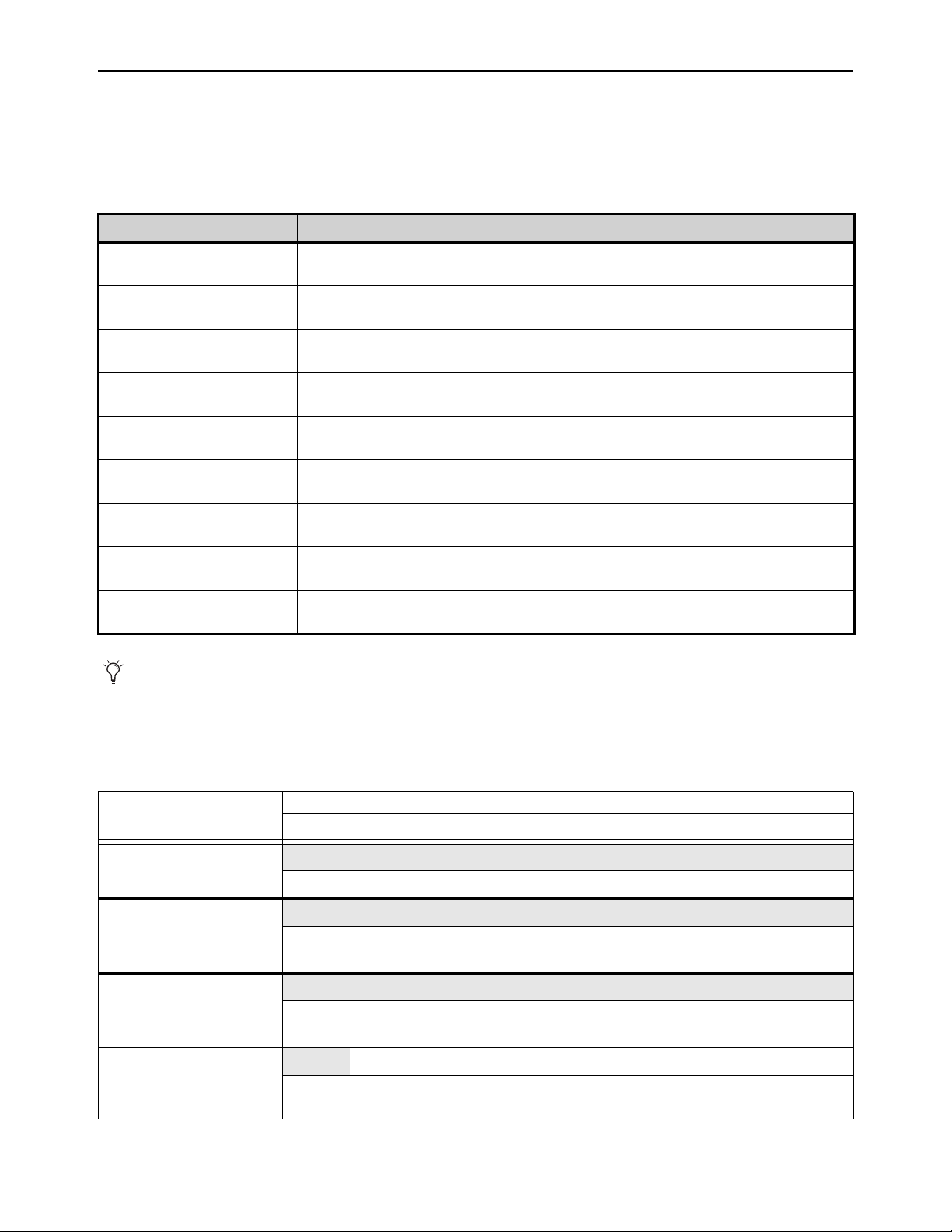
Events 319
Default Settings, Templates and Examples
Default Events
Each Demo Show file contains a set of default events that can be used as a starting point to build your own events. Some examples
of the types of default events for S6L include the following:
Examples
The following table provides a listing of example event definitions. Use the techniques explained throughout this chapter to add one
or more of the following events to establish your own set of events, triggers and actions.
Examples of default events
Default Event Type and Name Triggers Actions
Inputs (F1) Function Switch 1, Pressed Light Function Switch 1, On, While Active, Wait 0.0 sec.
Change View Mode - Inputs Page, Wait 0.0 sec.
Outputs (F2) Function Switch 2, Pressed Light Function Switch 2, On, While Active, Wait 0.0 sec.
Change View Mode - Outputs Page, Wait 0.0 sec.
Snapshots (F3) Function Switch 3, Pressed Light Function Switch 3, On, While Active, Wait 0.0 sec.
Change View Mode - Snapshots Page, Wait 0.0 sec.
Plug-Ins (F4) Function Switch 4, Pressed Light Function Switch 4, On, While Active, Wait 0.0 sec.
Change View Mode - Plug-Ins Page, Wait 0.0 sec.
Options(F5) Function Switch 5, Pressed Light Function Switch 5, On, While Active, Wait 0.0 sec.
Change View Mode - Options Page, Wait 0.0 sec.
Control (F6) Function Switch 6, Pressed Light Function Switch 6, On, While Active, Wait 0.0 sec.
Change View Mode - Control Page, Wait 0.0 sec.
Overview (F7) Function Switch 7, Pressed Light Function Switch 7, On, While Active, Wait 0.0 sec.
Change View Mode - Overview Page, Wait 0.0 sec.
Filing (F8) Function Switch 8, Pressed Light Function Switch 8, On, While Active, Wait 0.0 sec.
Change View Mode - Filing Page, Wait 0.0 sec.
Patchbay (F9) Function Switch 9, Pressed Light Function Switch 9, On, While Active, Wait 0.0 sec.
Change View Mode - Patchbay Page, Wait 0.0 sec.
To see the default (factory) Function key assignments, use the
Clear Console command.
Example Application of Event Elements, Triggers, and Actions
Example Application
Elements
Type
Menus Definition/Properties
If any input fader goes below
-60, mute that channel
Trigger
Control (Continuous) > Any Channel Any Channel, Fader, Below -60 dB
Action
Set Control (Switch) > Triggered Strip Triggered Strip, Mute
If any Input Channel meter
stays above +3 dB for 2 sec-
onds, engage Gain Guess on
that channel
Trigger
Meter > Any Channel Any Channel Meter, Above, +3 dB, 2 sec.
Action
Set Control (Switch) > Triggered Channel Triggered Strip, Input > Gain Guess, On
If any Input Channel meter
stays above +3 dB for more
than 3 seconds, lower the input
level on that channel by -3 dB
Trigger
Meter > Any Channel Any Channel Meter, Above, +3 dB, 3 sec.
Action
Set Control (Continuous) > Triggered Strip Triggered Strip, Fader, Relative, -3 dB
Pressing a Channel Color
switch puts that channel’s
Direct Out level on its fader
Trigger
Control (Switch) > Any Strip Any Strip, Color Switch, Pressed
Action
Continuous Control on Fader > Triggered
Strip
Triggered Strip, Direct Out, Toggle
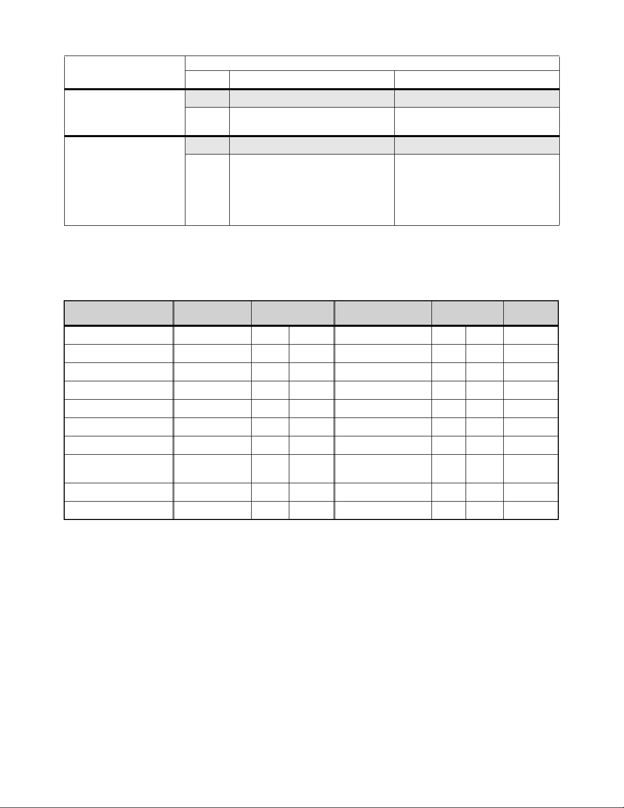
Events 320
Templates
The following table provides additional suggested event definitions. Use the techniques explained throughout this chapter to add
one or more of the following events to establish your own set of events, triggers and actions.
Using the Templates
To add any of the events listed in the table, do the following (using the first template, Talkback (Toggle) as an example):
To use the templates:
1 Create a new event.
2 Edit the event name (for example, “Talkback (Toggle)” as shown in the table). For renaming instructions, see
Renaming an
Event.
3 Select the (Trigger) Add pop-up menu and choose Footswitch > Switch 1 (Footswitch 1). The Switch 1 trigger type is added,
with a default State setting of Closed.
4 Select the (Action) Add pop-up menu and choose Talkback. The Talkback action is added. By default, the action State is Tog-
gle, and the behavior is Latched. There is no Wait (delay before firing) needed for this action.
Switch 1 (Footswitch 1) is now configured to toggle Talkback On or Off each time the footswitch is pressed.
If the spare vocal input Gate
closes, mute that input
Trigger
Gate > Channel <channel number/name> Closed
Action
Set Control (Switch) > Channel <channel
number/name>
<channel number/name>, Mute, On
Link a custom Layout to Sends
on Faders so that when you flip
that Aux to faders it spills in
that custom layout
(* Note: Requires that the
“Sends on Faders Follow AFL”
option is enabled for Mon bus
A or B, in Options > Buses)
Trigger
Control (Switch) > Aux <desired Aux) Aux <desired Aux>, Solo, On *
Action
Load Layout > Load Layout <Layout name> Load Layout <Layout name>
Suggested event definitions for common functions
Event Name Trigger Type
Trigger
Properties
Action Type
Action
Properties
Behavior
Talkback (Toggle) Footswitch Closed Talkback Toggle Latch
Talkback (Momentary) Footswitch Closed Talkback On While Active
Fader Start Fader Above Ch 1 -60 dB GPI Output 1 Closed Pulse (0.3 s)
Fader Stop Fader Below Ch 1 -inf dB GPI Output 1 Closed Pulse (0.3 s)
Fader Start/Stop Fader Above Ch 1 -60 dB GPI Output 1 Closed While Active
Mute Channel (Toggle) Footswitch 1 Closed Mute Ch 1 Toggle
Mute Group 1 (Toggle) Function Switch 9 Pressed Mute Group 1 Toggle Latch
Toggle Input Safe Switch
mode
Function Switch/ Pressed Input Safe Switch Mode
Tap Tempo Function Switch Pressed Tap Tempo
Pro Tools Start Record Function Switch Pressed Pro Tools > Record
Example Application of Event Elements, Triggers, and Actions
Example Application
Elements
Type
Menus Definition/Properties

Events 321
If you prefer momentary talkback, edit the event by doing the following.
1 Double-tap the Talkback action in the Actions list to access its editable properties.
2 Select the action State pop-up menu (it displays Toggle by default, or the current State setting) and select On.
3 Select the action Behavior pop-up menu and choose While Active. Together with the State setting (On), While Active estab-
lishes momentary control of the action; in this example, Footswitch 1 is now assigned to provide momentary Talkback control.
4 To quickly test the switch trigger, select the Test button, or press the Footswitch. Adjust the trigger State for your footswitch,
as necessary, for its open/closed orientation. (For instructions, see
Editing Trigger Type and Properties.)
5 After testing the trigger, select Reset to return the event to its Ready state.
Talkback State and Behavior after editing
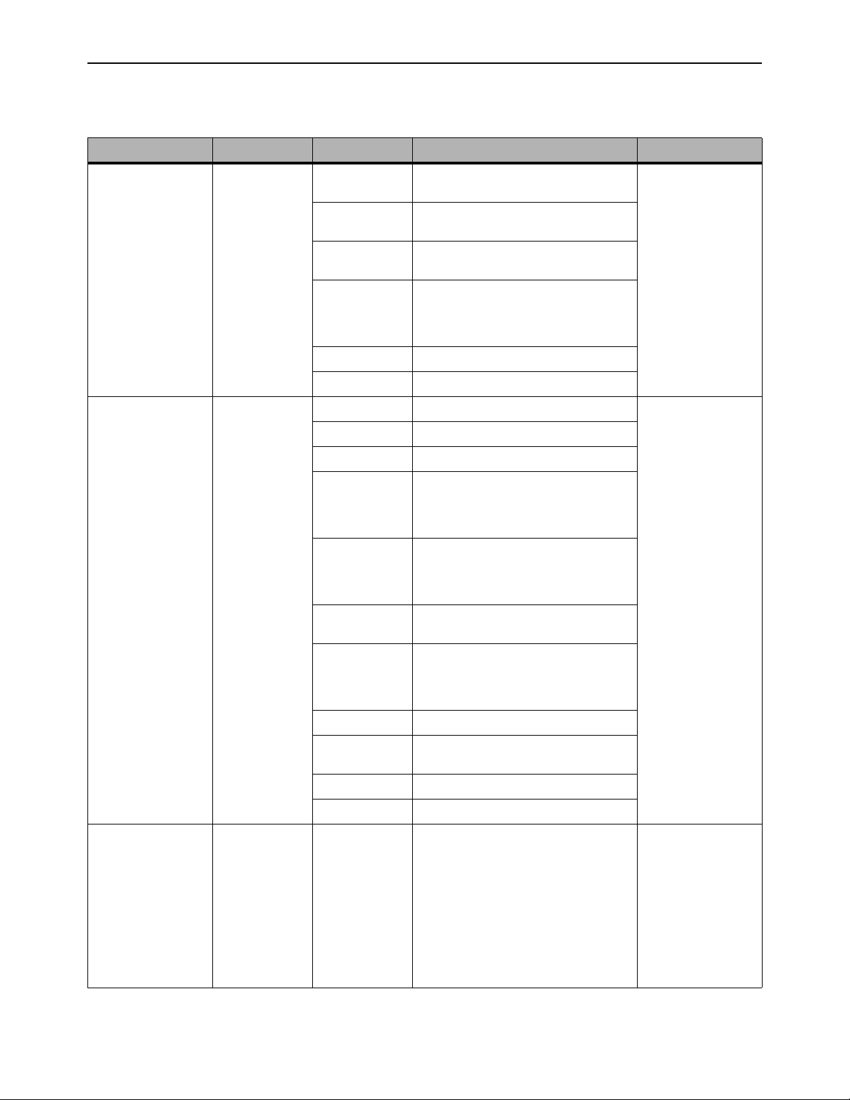
Events 322
Trigger Types
The following table lists the available trigger types and properties, along with a description of each.
Trigger Menus
Menu Property 1 Property 2 Property 3 Description
Control (Continuous) > Any Strip
Any Channel
Channel 1-n >
Any Aux
Aux 1-n >
Any Group
Group >
Any Matrix
Matrix >
Any Mains
Mains >
Any VCA
VCA 1-n >
Fader (default) Fader level, Above / Below, –inf to +12 dB
(Default: –60 dB)
Continuous control
moved below or above
threshold
Input > Pan (position), Width, Delay (ms), Direct
Out (level), HPF (freq.), LPF (freq.)
EQ > Gain, Frequency and Q for each of the four
bands on Inputs or seven bands on Outputs
Dynamics > Comp/Lim Threshold, Attack, Release,
Ration, Knee, Gain, Key LF and Key HF
Exp/Gate Threshold, Attack, Release,
Ratio, Hold, Range, Key LF, and Key HF
Aux 1 – n > Aux Send level
Inserts > HW Insert Position
Control (Switch) > Any Strip
Any Channel
Channel 1-n >
Any Aux
Aux 1-n >
Any Group
Group >
Any Matrix
Matrix >
Any Mains
Mains >
Any VCA
VCA 1-n >
Mute Switch Press (down)
Switch Release (up)
Solo
Attention
Control Surface > Color Switch
X Switch
Y Switch (see
Channel X / Y Function
Switches
)
Input > Fader Touch, Gain Guess, Input Direct,
Polarity, Delay In, Direct Out In, HPF In,
LPF In, Automation Safe, Solo Safe, Mains
L/R Assign, Mains C/M Assign
EQ > EQ In, EQ Analog Mode, In (per band), Bell
(per applicable band)
Dynamics > Comp/Lim In, SideChain In/HPF In/LPF
In/Listen
Exp/Gate In, SideChain In/HPF In/LPF
In/Listen
Aux Send 1 – n > IN
Aux Send
Pre/Post 1 – n
Pre/Post
Group Send > IN
Inserts > HW Insert Position
Meter > Any Strip
Any Channel
Channel 1-n >
Any Aux
Aux 1-n >
Any Group
Group >
Any Matrix
Matrix >
Any Mains
Mains >
Channel 1-n
Aux 1-n
Group 1-n
Matrix
Mains
Above / Below, threshold (dB), Hold (ms),
Release (ms)
Meter value
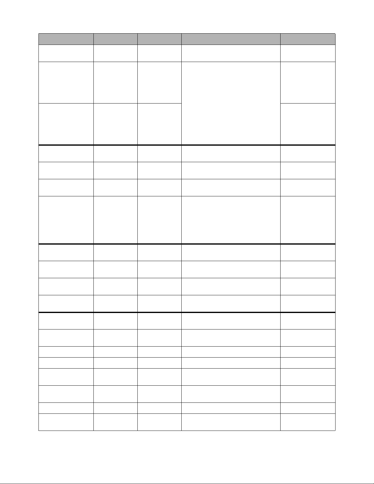
Events 323
Gate >
Any Channel
Channel 1-n >
Channel 1-n Open / Closed Gate status
Solo/AFL Monitor Bus
A >
Any
Input
Output
VCA
Solo In Place
(Monitor Bus A)
On (default) / Off Solo/AFL active/inac-
tive
Solo/AFL Monitor Bus
A >
Any
Input
Output
VCA
Solo In Place
(Monitor Bus B)
Solo/AFL active/inac-
tive
Function Switch > Function Switch
1–128
Pressed (default)
Released
Switch Press (down)
Switch Release (up)
Footswitch > Switch 1 (FS 1)
Switch 2 (FS 2)
Open
Closed (default)
Footswitch input high
Footswitch input low
GPI Input > GPI input 1-8 Open
Closed (default)
GPI Input high
GPI Input low
MIDI Input >
Note on/off
Poly Key Pres.
Control Change
Program Change
Channel Pres.
Pitch Bend
MMC commands
Channel, Note, Velocity, Value, LBS, MSB
Target Device ID (MMC only)
Properties vary with
MIDI trigger Type
Recall Snapshot > Snapshot num-
ber and name
Event triggered by
snapshot Recall
Preview Mode On (default)
Off
Preview Mode
active/inactive
Snapshot Update
Mode
On (default)
Off
Update Mode
active/inactive
Edit Mode On (default)
Off
Edit Mode active/inac-
tive
Talkback On (default)
Off
Talkback active/inac-
tive
Flip to Faders On (default)
Off
Flip to Faders
active/inactive
Show Mode Active Show Mode is active
Config Mode Active Config Mode is active
System Start System software ini-
tialized
Time 00:00:00 Clock time (24 hour
format)
Time Code 00:00:00:00 LTC, MTC
Plug-In Rack Ready Mirrors plug-ins rack
Ready state
Trigger Menus
Menu Property 1 Property 2 Property 3 Description
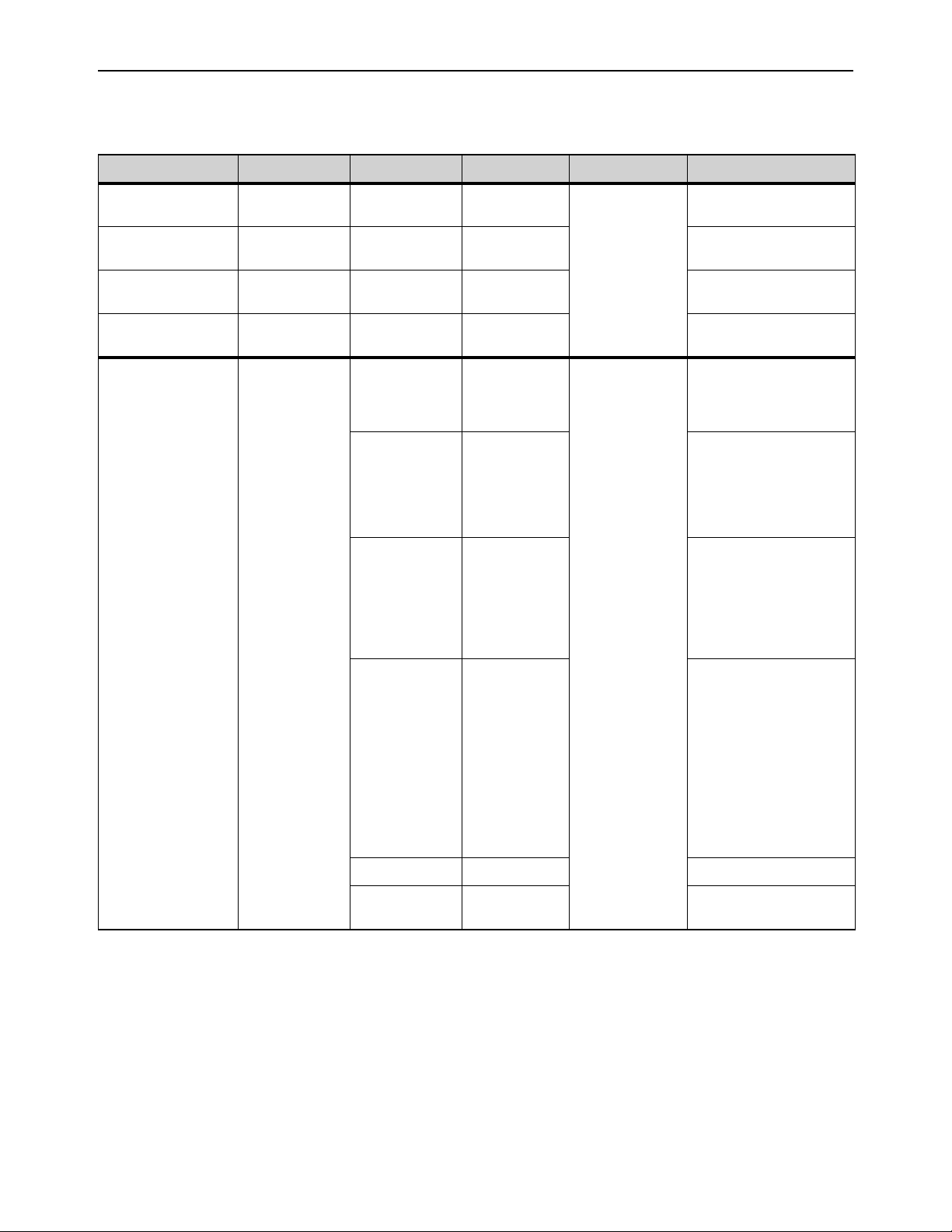
Events 324
Action Types
The following table lists the available Action types and properties, along with a description of each.
Table 6. Action types
Menu Property 1 Property 2 Property 3 State/Behavior Description
Attention Next Chan-
nel
Wait (0.0 sec. def.) Selected Channel
advances by one
Attention Previous
Channel
Selected Channel reverses
by one
Copy Attentioned
Channel
Channel copy operation
Paste to Attentioned
Channel(s)
Channel paste operation
Set Control (Continu-
ous) >
Triggered Strip
Channel 1-n >
Aux 1-n >
Group 1-n >
Matrix >
Mains >
VCA >
Fader (default) Fader level –inf
to +12 dB
(Default:
–60 dB)
• Absolute or Rela-
tive
• X-Fade (and vari-
able shapes)
• Wait (0.0 sec.
def.)
Input > Pan (position),
Width, Delay
(ms), Direct Out
(level), HPF
(freq.), LPF
(freq.)
EQ > Gain, Fre-
quency and Q
for each of the
four bands on
Inputs or seven
bands on Out-
puts
Dynamics > Comp/Lim
Threshold,
Attack, Release,
Ration, Knee,
Gain, Key LF
and Key HF
Exp/Gate
Threshold,
Attack, Release,
Ratio, Hold,
Range, Key LF,
and Key HF
Aux 1 – n > Aux Send level
Inserts > HW Insert Posi-
tion
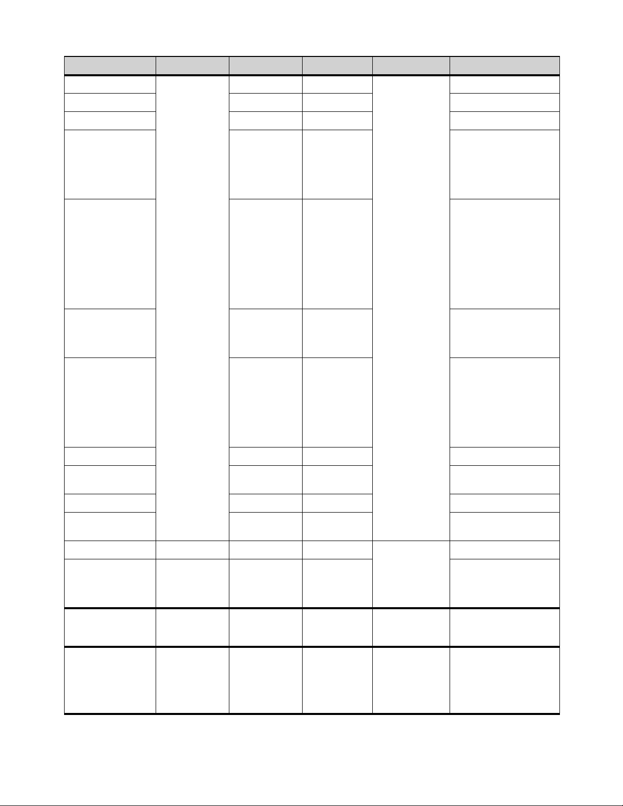
Events 325
Set Control (Switch) Triggered Strip
Channel 1-n >
Aux 1-n >
Group 1-n >
Matrix >
Mains >
VCA >
Mute • Switch Press
(down) / Switch
Release (up)
• Latch (default) /
While Active
• Wait (0.0sec
default)
Solo
Attention
Control Surface > Flash Color
Switch
Light X Switch
Flash X Switch
Light Y Switch
Flash Y Switch
Input > Gain Guess,
Input Direct,
Polarity, Delay
In, Direct Out In
HPF In, LPF In
Automation Safe
Solo Safe
MainsL/R Assign
MainsC/M
Assign
EQ > EQ In, EQ Ana-
log Mode, In (per
band), Bell (per
applicable band)
Dynamics > Comp/Lim In,
SideChain
In/HPF In/LPF
In/Listen
Exp/Gate In,
SideChain
In/HPF In/LPF
In/Listen,
Aux Send 1 – n > IN
Aux Send
Pre/Post 1 – n
Pre/Post
Group Send > IN
Inserts > HW Insert Posi-
tion
Mute Group > Mute Group 1–n • On/Off/Toggle
(def.)
• Latch (default) /
While Active
• Wait (0.0 sec.
def.)
Toggle Mute group status
Mute All Stage Outputs Mutes all outputs of all
assigned Stage 64 boxes
Clear Solos > Monitor Bus A
Monitor Bus B
Clear All
Wait (0.0 sec. def.) Mirrors Solo Clear
Bypass Plug-In Rack names 1-5 Slots 1-25 • On/Off/Toggle
(def.)
• Latch (default) /
While Active
• Wait (0.0 sec.
def.)
Table 6. Action types
Menu Property 1 Property 2 Property 3 State/Behavior Description
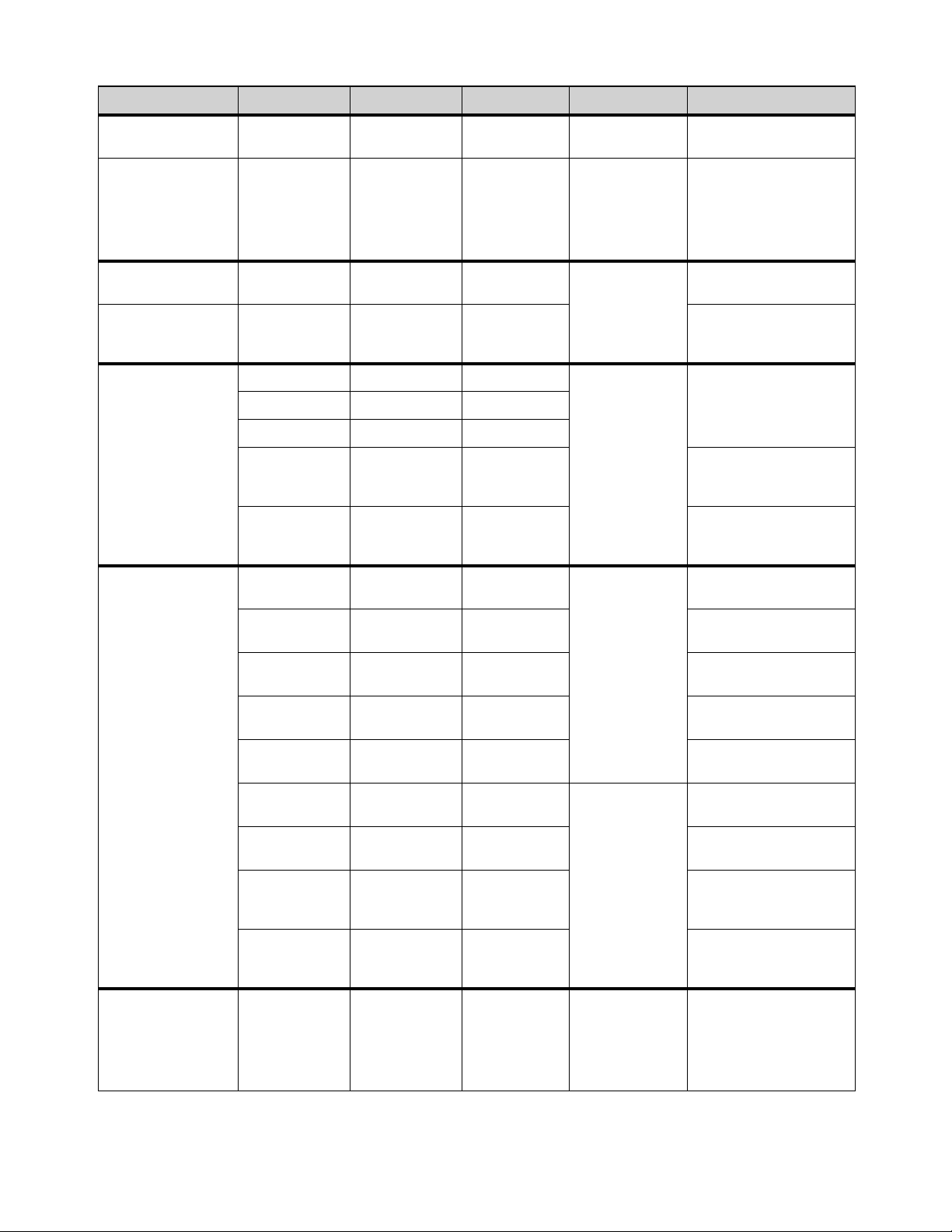
Events 326
Change View Mode > Software screen
pages
Wait (0.0 sec. def.) Targets selected pages
on-screen
Set Fader Banking
Mode >
Split Banking
Inputs
Outputs
VCAs
Layouts
• On/Off/Toggle
(def.)
• Latch (default) /
While Active
• Wait (0.0 sec.
def.)
Light Function Switch
>
Light Function
Switch 1–n
• On/Off/Toggle
(def.)
• Latch (default) /
While Active
• Wait (0.0 sec.
def.)
Lights Function switch
Flash Function Switch
>
Flash Function
Switch 1–n
Flashes Function switch
Pro Tools > Stop Wait (0.0 sec. def.) Transport controls for
Pro Tools playback and
recording
Play
Record
Record Enable
All VENUE
Tracks
Tracks in Pro Tools with a
VENUE I/O path are record
armed (enabled).
Record Disable
All VENUE
Tracks
Tracks in Pro Tools with a
VENUE I/O path are record
disarmed.
Snapshots > Recall Snapshot
>
Snapshot num-
ber and name
Wait (0.0 sec. def.) Recall specified snapshot
Recall Next
Snapshot
Mirrors Snapshot Next but-
ton
Recall Previous
Snapshot
Mirrors Snapshot Previous
button
Recall Selected
Snapshots
Mirrors Snapshot Recall
button
Store to Selected
Snapshot
Mirrors Snapshot Store but-
ton
Preview Mode • On/Off/Toggle
(def.)
• Latch (default) /
While Active
• Wait (0.0 sec.
def.)
Activate/deactivate Pre-
view Mode
Snapshot Update
Mode
Update mode active while
trigger is true
Absolute Edit
Mode
Enters Edit mode when trig-
ger is true; exits via Abso-
lute when trigger goes false
Relative Edit
Mode
Enters Edit mode when trig-
ger is true; exits via Relative
when trigger goes false
GPI Output > Output 1–8 • Open/Closed
(default)/Toggle
• Pulse, 0.3s
(default)
• Latch/While
Active
Pulses or latches selected
GPI Output
Table 6. Action types
Menu Property 1 Property 2 Property 3 State/Behavior Description
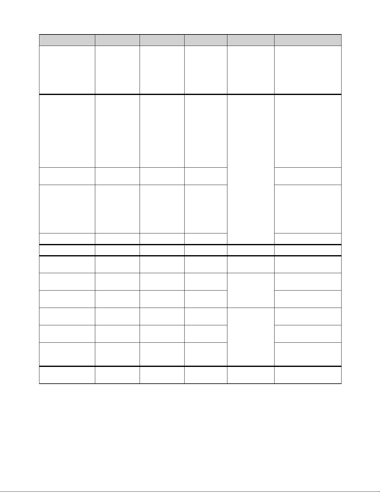
Events 327
MIDI Output > Note on/off
Poly Key Pres.
Control Change
Program Change
Channel Pres.
Pitch Bend
MMC commands
Channel, Note,
Velocity, Value,
LBS, MSB
Target Device ID
(MMC only)
Wait (0.0 sec. def.)
GEQ on Faders > Toggle GEQ on
Faders
S6L-32D:
• GEQ 20–20k
Hz
S6L-24D and
S6L-24:
• GEQ 20–630
Hz
• GEQ 800–20
kHz
• On/Off/Toggle
(def.)
• Latch (default) /
While Active
• Wait (0.0 sec.
def.)
Assigns Graphic EQ con-
trols to the faders for the
selected channel
Sends on Faders > Triggered Strip
Aux 1-n
Engages Sends on Faders
mode
Continuous Control on
Fader
Triggered Strip
Channel 1-n >
Aux 1-n >
Group 1-n >
Matrix >
Mains >
Input
EQ
Dynamics
Auxes
Matrix Sends
Matrix Pans
Inserts
all continuous
controls
Flips the Action control to
the fader
Engage Flip to Faders Mirrors the
Flip switch
Load Layout Layout Name Wait (0.0 sec. def.) Load specified Layout
Flash Console Light
Bar
Wait (0.0 sec. def.) Flashes console lights
Disable Bank Safe • On/Off/Toggle
(def.)
• Latch (default) /
While Active
Wait (0.0 sec. def.)
Disables any currently Bank
Safed channels
Talkback Toggles the Talkback output
on/off
Input Safe Switch
Mode
Wait (0.0 sec. def.) Cycles through Input Safe
Switch modes
Output Safe Switch
Mode
Cycles through Output Safe
Switch modes
Tap Tempo Sets the system tempo to
synchronize delay plug-ins
that support Tempo Sync
Cancel Operation Wait (0.0 sec. def.) Mirrors Cancel switch (and
Esc key on keyboard)
Table 6. Action types
Menu Property 1 Property 2 Property 3 State/Behavior Description
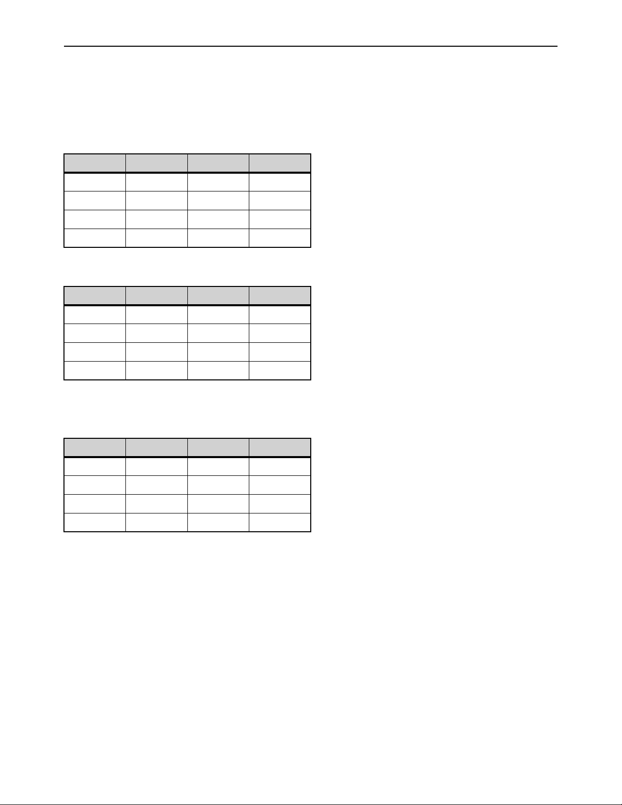
Events 328
Examples of Logical Operators
Logical operators determine the precise state required in order for an event to occur as shown in the following tables:
OR
At least one of the triggers must be true. The following table shows the effect of OR on events with multiple triggers. In the
table, 0 indicates a false condition (not occurring) and 1 indicates a true condition (occurring).
When using OR, if one or more (but not all) of the triggers go false, the event logic is only acted on again when all triggers evaluate
to false (result = 0).
AND
All triggers must be true. The following table shows the effect of AND on events with multiple triggers. In the table, 0 indi-
cates a false condition (not occurring) and 1 indicates a true condition (occurring).
XOR
At least one trigger, but not all, must be true. The following table shows the effect of XOR on events with multiple triggers. In the
table, 0 indicates a false trigger condition (not occurring) and 1 indicates a true condition (occurring).
Trigger A Operator Trigger B Result
0OR00
0OR11
1OR01
1OR11
Trigger A Operator Trigger B Result
0AND00
0AND10
1AND00
1AND11
Trigger A Operator Trigger B Result
0XOR00
0XOR11
1XOR01
1XOR10
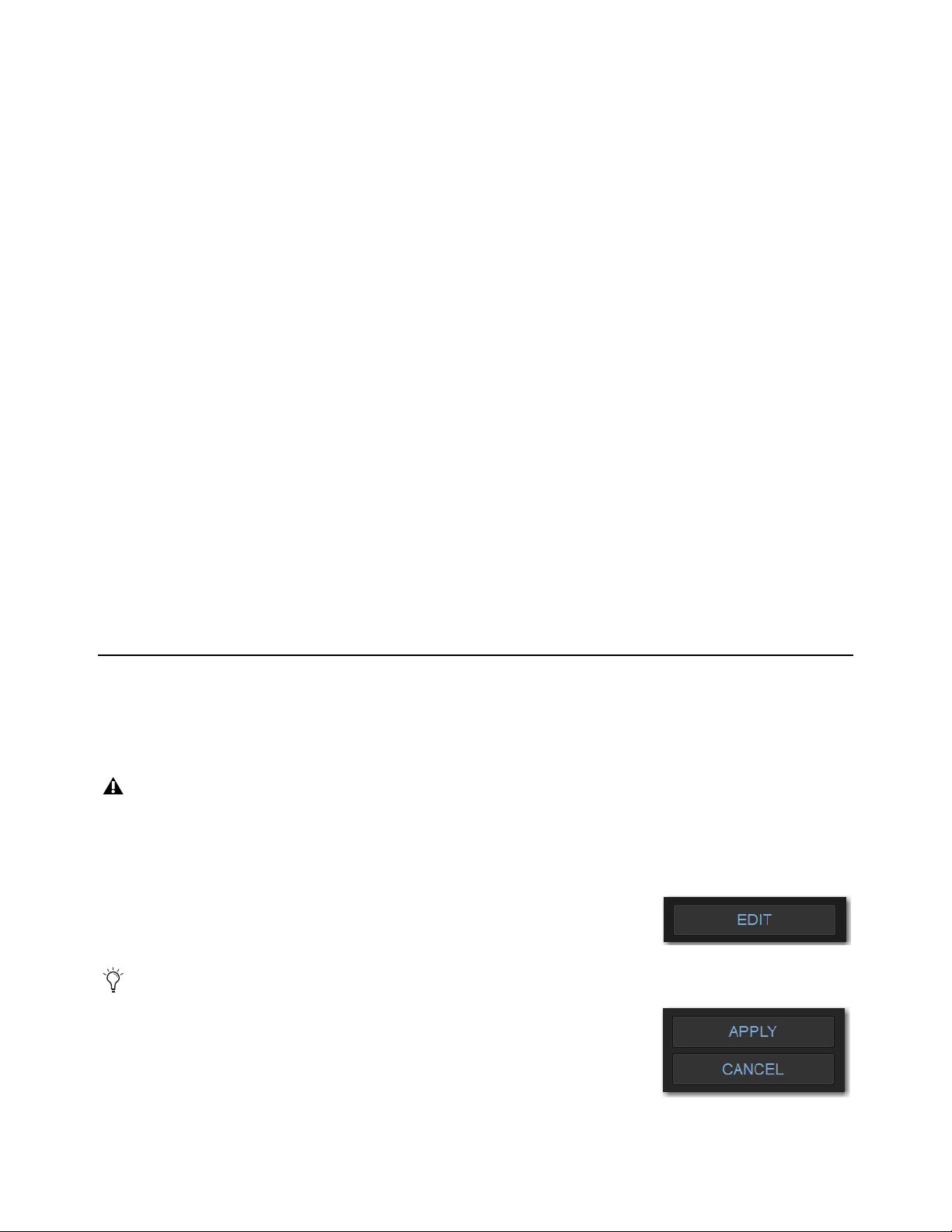
Options 329
Options
The Options page provides several tabs. Of these, the System and Devices tabs are where most system configuration settings and
options are enabled and customized:
• The System tab provides the primary tools by which you configure mixing, routing, and processing options.
• The Devices tab provides status, diagnostics, and options for hardware components.
This chapter shows you how to manage the most important System and Devices settings, and describes the settings available in
other Options screens.
Overview of Options
The Options page provides the following tabs:
• System
• Buses
• Pickoffs
• Snapshots
• Misc
• Interaction
• Devices
• Plug-Ins
• Plug-Ins (see Installing and Authorizing Plug-Ins)
System
From the System tab you can configure inputs, Main and Mix buses, reset and shut down your system, lock the system, and get sys-
tem info.
Settings available in the System tab can only be edited while in Config mode.
To change a system configuration option:
6 Put the system in Config mode.
7 Go to the Options page and select the System tab.
8 Select Edit.
9 Change a Mains Bus or Mix Bus Configuration, or enable or disable Virtual Soundcheck
or Input mode.
10 Select Apply to confirm and apply your new settings, or Cancel to cancel the operation.
11 Return to Show mode when you are finished editing settings.
Changing system settings may restart and/or interrupt audio.
Select the Cancel button to return to the previous setting.

Options 330
System Configuration
In Show mode, the System Configuration section is display-only, showing the current allocation of system resources and bus set-
tings.
In Config mode, you can edit system settings such as input channel configuration, bus configurations, and hardware I/O configu-
rations.
Engine
This section shows the following information:
Internal Processing
Shows the current sample rate of the S6L system.
HDX Mix Engines
Shows the number of HDX TDM cards are installed in the currently paired E6L Engine.
DSPs for Plug-Ins
Shows the amount of DSP available for plug-ins is pre-configured, and cannot be changed.
Processing
Input Channels
Shows the maximum number of input processing channels available on your system, and is determined by the
model of E6L engine your S6L control surface is currently paired with.
Matrixes
Shows the number of available Matrix Mixers, and is determined by the model of E6L engine your S6L control surface
is currently paired with.
VCAs
Shows the number of available VCAs.
Mute Groups
Shows the number of available Mute Groups (24).
Graphic EQs
Shows the number of available Graphic EQs (32).
System Inputs
This setting lets you globally choose between using Stage inputs or Pro Tools inputs as the source for your system input channels.
You can also specify AVB Input or Virtual Soundcheck, or MADI Input or Virtual Soundcheck as the input source. MADI Input
or Virtual Soundcheck requires one or more MADI-192 MADI Option cards.
System Outputs
This setting lets you choose AVB, MADI (MADI-192 MADI Option cards), or both as the Virtual Soundcheck Destination.
Mains Bus Configuration
The Mains Bus settings let you choose the overall configuration for the Main buses.
Mix Bus Configuration Settings
These options settings let you choose the overall Aux and Group bus configuration.
Audio is interrupted when a System Configuration setting is applied. Do not change these settings during a performance.
System configuration settings are stored with Show files. See
System Configurations and Loading Shows for more infor-
mation.
See
Pro Tools Recording and Playback for more information.
For instructions, see
Configuring the Mains Bus.
For instructions, see
Configuring Mix Buses.

Options 331
System
This section provides the Shutdown, Info (system information export), Update, and Lock buttons. These buttons are also available
on the MTS (press the Gear icon, then tap to display the General tab).
Info
System Information Export
The System Information Export feature lets you generate an HTML (text) document that details system hardware, software and cur-
rently loaded Show file configurations. This document can be read by any Internet browser, such as Internet Explorer, Mozilla Fire-
fox, Safari, or Chrome.
The System Information document can be sent directly to production or rental companies to describe your exact system needs; al-
ternately, the information can be re-formatted as desired by copying and pasting the data into a word processing or spreadsheet ap-
plication.
To export VENUE System Information:
1 Insert a USB storage device into any available USB port on the S6L control surface.
2 Go to Options > System.
3 Select the Info button.
4 Do any of the following:
• If you have more than one USB storage device connected, make sure the correct USB device is selected. If it is not, select Next
Disk to cycle through each available disk until the correct one is selected.
•Select
Save to proceed and export system info to the selected USB disk.
•Select Cancel to dismiss the dialog without exporting.
5 Select OK to confirm the export procedure.
You can now remove the USB device —from there, you can transfer the exported file to a personal computer for printing, format-
ting, archiving or distribution.
Update
The Update button is used to perform software updates on your system, and to install ECx Ethernet Control host software. Updates
performed using the Update button are distinct from System Restores and Software Updates.
Lock
You can lock and hide surface and on-screen controls.
To engage System Lock:
1 Go to Option > Systems.
2 Select the Lock button in the System section.
3 In the dialog that appears, select Lock.
On-screen, an Unlock button appears in the lower right corner in front of a dimmed background image.
To unlock the system (disengage System Lock):
Do either of the following:
• Press and hold the Cancel switch on the S6L control surface for two seconds.
– or –
•Select Unlock in the lower right corner of the screen.
The patch list can also be exported separately (for more information, see
Patch List Export).
The Unlock button is hidden after a few seconds. Touch the screen, mouse or keyboard to bring it back.

Options 332
System Status while Locked
GPI
All system GPI inputs and outputs are disabled while the system is locked.
Footswitches
All Footswitch inputs are disabled while the system is locked.
Events
All Event triggers and actions are disabled while the system is locked.
MIDI and Time Code
While the system is locked:
• Snapshots continue to be recalled via MTC/LTC, either internally or externally generated.
• The system continues to respond to snapshot changes via incoming MIDI program change commands if the Snapshots Re-
spond option is selected on the Options > Snapshots page.
• The system continues to send MIDI program changes when a snapshot is recalled if the Snapshots Send option is selected on
the Options > Snapshots page.
• The system continues to send MIDI messages stored within snapshots, provided the MIDI data type is scoped.
Customizing the System Lock Display
You can manually add one or more custom images to display during System Lock, rather than the default Avid logo background.
Multiple images are displayed one after the other for 20 seconds in a random order. (Pressing the Spacebar advances to the next im-
age immediately.)
To install custom System Lock images:
1 Make sure you have connected a keyboard and trackball (or mouse) the S6L control surface.
2 Copy a BMP or JPG image file to a USB storage device. (For optimal results image resolution should be 1920x1080; smaller
or larger images can be used, but will be centered or scaled, respectively.)
3 Put the system into Config mode.
4 Go to Options > System, Ctrl-click the ShutDown button, confirm you want to Exit to the Desktop.
5 Copy the image from your USB storage device to the following location on the system drive:
User Data(D):\D-Show\Images.
6 Double-click the Return to VENUE software icon on the Desktop to restart VENUE software.
Troubleshooting
This section provides the following troubleshooting options:
Clear Console
The Clear Console button resets all parameters on all channels to their factory default settings.
Run System Test
System Test is hardware diagnostics software for the system. Not all versions of VENUE software provide Sys-
tem Test in
Options > System.
Only use System Test at the request of a qualified VENUE technician to diagnose specific hardware problems.
VENUE Software
This shows the version of VENUE software currently installed on your S6L system.
MTC/LTC can be disabled using the CHASE MTC/LTC button on the Snapshots page. Also, the sending and receiving of MIDI
data can be turned off by deselecting the MIDI options on the Options > Snapshots page.
To restore the default Avid logo Lock screen, delete any custom images from the Images folder.
Performing a Clear Console also resets the time code start time to the default of 01:00:00:00, and generates a new (default)
OnStagePassword.example.txt file.
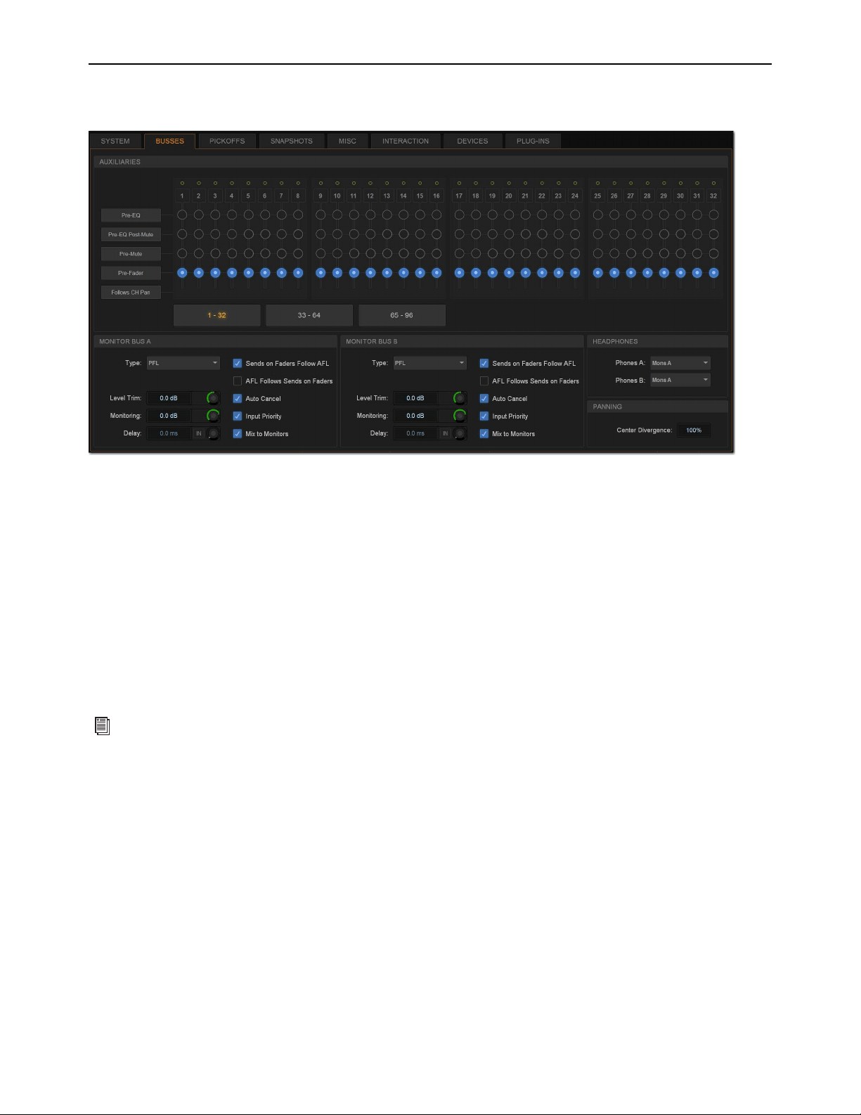
Options 333
Buses
The Buses tab lets you customize characteristics for the Aux, Solo, Matrix, and Main buses.
Auxiliaries
These options and indicators let you designate pickoff point of the Aux Sends feeding Aux outputs. Auxes are oriented vertically
in columns, and the channel number of the Aux is shown at the top of the column.
Mono/Stereo Indicator
Shows whether the Aux output is mono (single yellow circle) or stereo (interlocking green circles). Mono
Auxes can be combined into stereo channels using the Make Stereo command (see
Make Selected Mono Strips Stereo/Make Se-
lected Stereo Strip Mono).
Pickoffs
These options let you designate the pre-fader pickoff point feeding each bus. Choices include Pre-EQ, Pre-EQ Post-Mute,
Pre-Mute, and Pre-Fader (post-mute).
Aux Select Buttons
These buttons let you access the pickoff options of the Aux outputs indicated on the button. Any Aux outputs
currently unavailable are greyed out in the grid.
Follows Channel Pan
Each channel can be panned independently within each stereo Aux, or configured to follow the channel pan
by enabling the Follows Channel Pan option.
Buses tab of the Options tab
For more information on Aux/Variable Group pre-fader pickoff points, see
Selecting Aux Pre-Fader Pickoff Points.
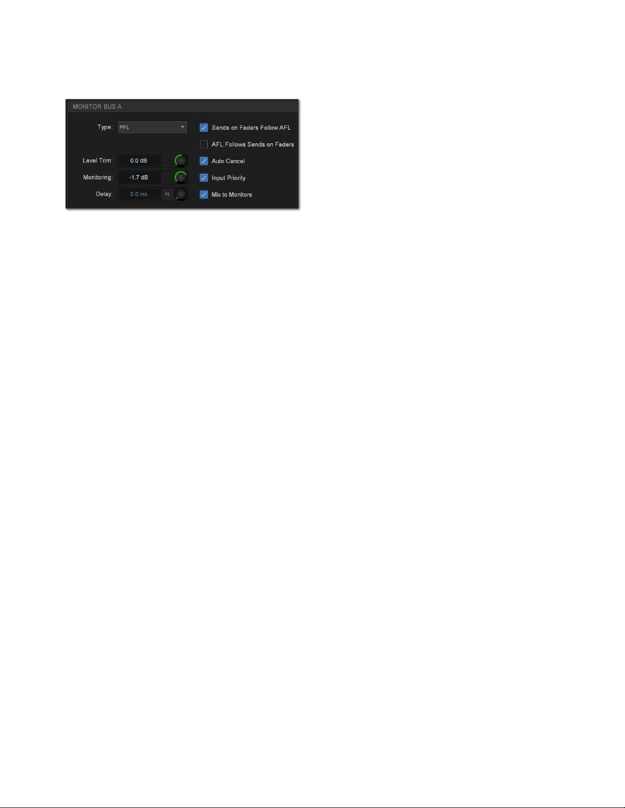
Options 334
Solo and Monitor Operations
These settings customize Solo and Monitor bus mode and operation. See Configuring the Monitor Buses and Solo Options for
more information.
Headphones
These settings let you set the Monitor bus that feeds each S6L control surface front-panel headphone output. With S6L-16C, a sin-
gle headphone output (Phones) is available.
Panning (Mains Center Divergence)
When the Main buses are set to L–C–R (Left-Center-Right) mode, the Center Divergence setting determines the amount of cen-
ter-panned signal sent to the center output.
When Center Divergence is set to 100%, a channel panned to center is sent to the center output only.
When Center Divergence is set to 0%, a channel panned to center is sent equally to the left and right outputs only (phantom cen-
ter).
A Center Divergence setting between 0% and 100% sends a center-panned channel to the left, center, and right outputs with the
center channel more prominent as the value increases towards 100%.
To set Center Divergence:
1 On the external screen, go to Options > Buses.
2 In the Panning section, select in the Center Divergence field and drag up/down to increase/decrease the value (or type in a new
value).
3 Press Enter or Return on your keyboard to confirm the setting.
Monitor bus options on the Options > Buses tab
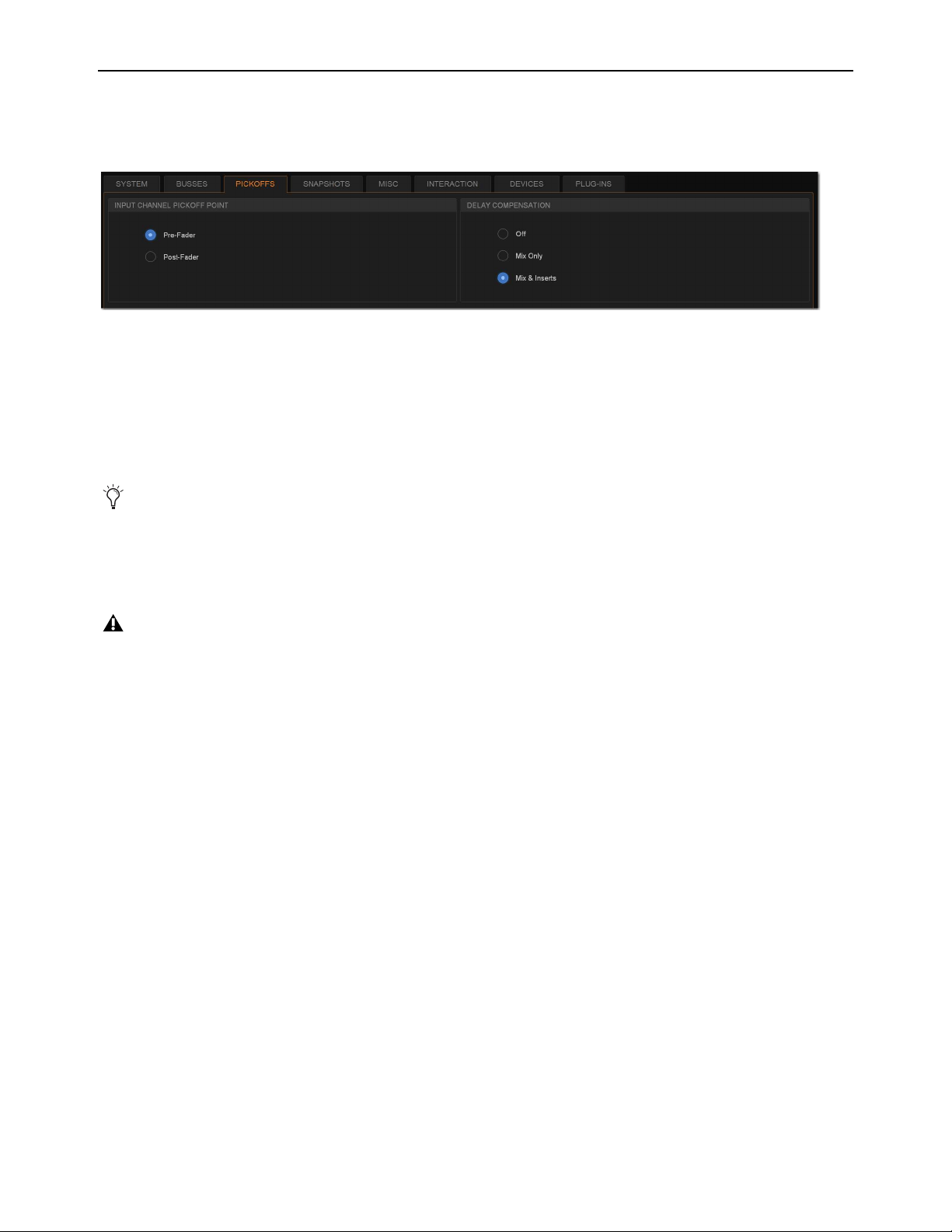
Options 335
Pickoffs
The Pickoffs tab lets you control the bus pickoff point on input strips. The Pickoffs tab also provides master control for Delay Com-
pensation.
Input Channel Pickoff Point
Set the global Input Channel Pickoff Point by selecting Pre-Fader or Post-Fader.
Delay Compensation
Three settings for Delay Compensation are provided, as follows:
Off
No Delay Compensation is applied.
Mix Only
VENUE automatically compensates for delays incurred by the use of plug-ins.
Mix and Inserts
VENUE automatically compensates for delays incurred by the use of plug-ins.
Pickoffs tab of the Options page
Delay Compensation can be set in either Show or Config mode.
When Delay compensation is set to Mix & Inserts, inserts on Auxes will be compensated. This may cause phase issues with some
configurations and routing based on legacy (pre-S6L) systems.
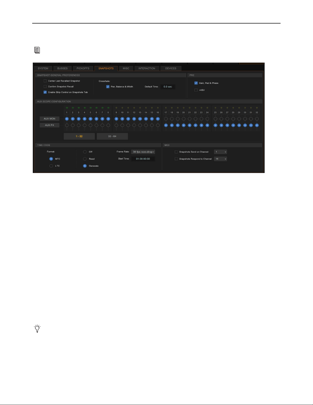
Options 336
Snapshots
The Snapshots tab provides several snapshot preference settings to optimize snapshot operation.
Snapshot General Preferences
The following settings are available in the Snapshots tab.
Center Last Recalled Snapshot
Manages the display of the Snapshots list so that the last recalled snapshot is always centered
vertically, letting you maintain display of adjacent snapshots in the list.
Confirm Snapshot Recall
When this setting is enabled, a confirmation dialog appears when any snapshot is recalled asking to
confirm the operation. When not enabled, recalling snapshots requires no confirmation.
Enable Strip Control on Snapshots Tab
Allows adjustment of faders, Solo, Mute, and Safe controls on-screen in the Snapshots
tab Channel Strip Controls. Disable this setting to preserve legacy behavior.
Crossfade Pan, Balance, and Width
All Pan, Balance and Width parameters follow the default snapshot crossfade time.
Default Crossfade Time
Defines the length of time it takes to crossfade between fader levels when recalling snapshots. Maximum
crossfade time is 99.9 seconds.
PRE
The options in the PRE section let you specify which parameters are recalled with Snapshots whose scope includes Pre settings. Se-
lect to toggle whether recalled Input snapshot data includes the following:
• Gain, Pad, and Phase
• +48V (phantom power)
For more information on using snapshots, see
Snapshots.
Snapshots tab of the Options page
Delay is stored as a unique (discrete) data type for each channel.

Options 337
Aux Scope Configuration
These settings let you classify individual Aux Sends (including linked bus pairs) as monitor sends (“Aux Mon”) or as effects sends
(“Aux FX”) as they apply to the Snapshots Data Type Scope buttons.
This option is for organizing Aux Sends for snapshot control only, and does not directly affect Aux bus operation. You can use the
User Aux Scope tab (Snapshots > User Aux) to include or exclude individual Auxes from snapshots, in addition to their classi-
fication as Aux Mon or Aux FX.
Time Code
The Time Code options let you choose the current time code format, operational modes, frame rate, and Start Time.
Format
Choose between MTC and LTC for the current time code format. Only one time code format may be selected at a time.
Modes
Available time code modes for MTC are Off, Read (slave), and Generate (master). Available time code modes for LTC
are Off and Read (slave).
Frame Rate
This option sets the frame rate that is used when generating MTC.
Start Time
This option sets the start time that is used when generating MTC (default is 01:00:00:00). When chasing MTC or LTC,
make sure the Start Time is earlier than the start of incoming time code.
MIDI
These settings designate the MIDI channel on which Snapshots send or receive MIDI Bank Select and Program Change informa-
tion.
Snapshots Send on Channel
This option sets snapshots to send Bank Select and Program Change commands on a selected MIDI
channel. This provides a quick and easy way to send a MIDI command every time a snapshot is fired, without having to embed a
MIDI program change within each snapshot.
Snapshot Send on Channel does not need to be turned on in order to send other types of MIDI data that are embedded in snapshots,
such as note on/off or MMC.
Snapshots Respond to Channel
This option sets snapshots to respond to incoming Bank Select and Program Change commands
on the selected MIDI channel.
See
Synchronization for more information.
See Synchronization for more information.
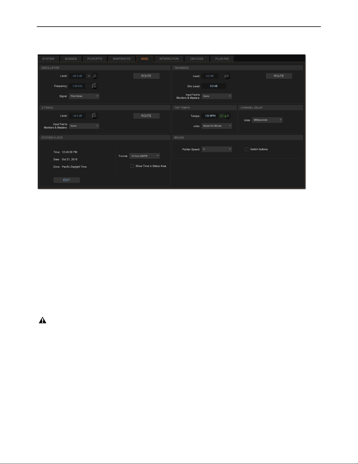
Options 338
Misc
The Miscellaneous (Misc) tab provides utility and other settings.
Oscillator
The Oscillator provides selectable signal type, frequency (for Variable Sine) and signal level, as well as a master on/off switch. The
output of the Oscillator can patched to input channels using the Patchbay (see Patching Input Sources to Input Channels), and
can be routed directly to output buses using Route to Attentioned mode.
Routing the Oscillator to Output Buses
To route the Oscillator to an output bus:
1 Go to the Options page and select the Misc tab.
2 In the Oscillator section, select the Route button. The switch flashes to indicate Route to Attentioned mode.
3 Go to the Outputs page and attention one or more output fader strips. The attentioned fader strips flash.
4 In the confirmation dialog that appears, select Route to confirm your assignment, or select Cancel to cancel without changing
the current routing.
Configuring the Oscillator and Setting Level
The Oscillator is configured on-screen, and can be activating on-screen or from the Global Control encoders.
To configure the Oscillator:
1 Go to Options > Misc.
2 As a precaution, drag the on-screen Level encoder in the Oscillator section to set the Oscillator level to off before you go any
further.
Misc tab of the Options page
Signals are routed to output buses post-mute and post fader.
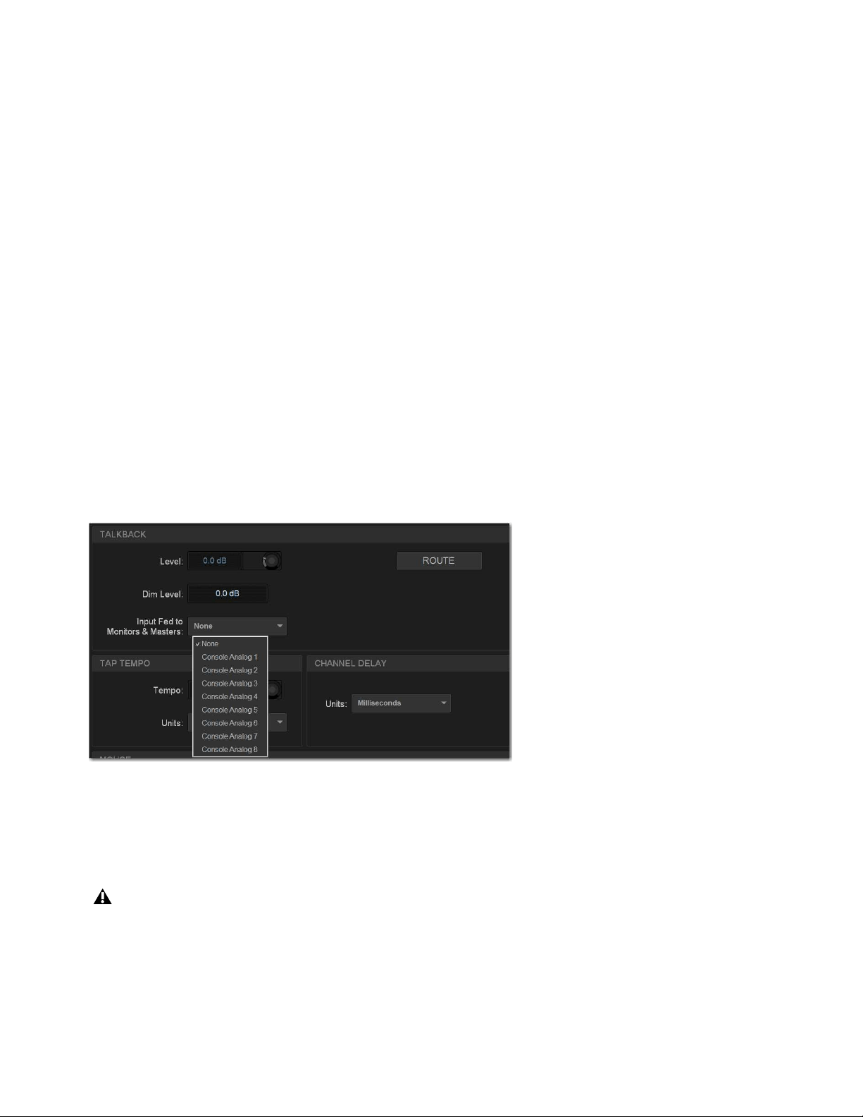
Options 339
3 Select the Signal pop-up and select from the following signal types:
• 100 Hz Sine
• 1 kHz Sine
• 10 kHz Sine
• Variable Sine
• Pink Noise
• White Noise
4 If you select Variable Sine, you can set the sine wave frequency with the on-screen frequency control (directly to the right of
the Signal pop-up).
5 Select the on-screen In button to activate the Oscillator.
Oscillator level appears on the Console Assignable Encoder whenever the Oscillator is In. If Talkback is engaged, it replaced the
Oscillator on the Assignable Encoder.
6 Slowly drag the on-screen Level encoder to set the Oscillator level.
Talkback
You can route a single Console analog input directly into any output bus using the Talkback circuit. This allows you to send Talk-
back to outputs (such as Auxes feeding stage monitors) without having to use a system channel.
Routing Talkback to Output Buses
To route Talkback to an output bus:
1 Go to Options > Misc.
2 In the Talkback section, select the Input Fed to Monitors and Masters pop-up and choose a hardware input source.
3 Select Route. The switch lights to indicate Route to Attentioned mode.
4 Go to the Outputs page and attention one or more output fader strips. The attentioned fader strips flash.
5 In the confirmation dialog that appears, select Route to confirm your assignment or select Cancel to cancel without changing
the current routing.
Choosing a Talkback input
Signals are routed to output buses post-mute and post fader.

Options 340
Activating Talkback Input and Setting Level
Talkback can be adjusted on-screen, or from the Assignable Encoder on the MLM.
To activate and set the level for Talkback input on-screen:
1 Go to Options > Misc.
2 Select the on-screen In button in the Talkback section to activate the Talkback input.
3 Drag the on-screen Level knob to set the Talkback level.
To activate and set the level for Talkback from the MLM:
1 In the Assignable Encoder (Touch and Turn) section of the MLM, press and hold the Talkback switch.
2 Rotate the Assignable Encoder to adjust Talkback level.
Setting Talkback Dim Level
When Talkback is sent directly to an Output bus, the bus program material (minus the Talkback signal) is automatically reduced
by the amount specified in the Dim Level setting.
To set the Talkback Dim Level:
1 Go to Options > Misc.
2 In the Talkback section, double-tap the Dim Level text box and enter a Dim Level value in the range –60 dB (maximum gain re-
duction) to 0 dB (no gain reduction).
2-Track Inputs
You can route a pair of Console or Engine analog or digital hardware inputs directly into output buses using the 2-Track inputs. This
allows you to send audio to the selected outputs without using a system channel. Use this feature to perform tasks such as confirm-
ing system audio output.
Routing 2-Track to Output Buses
To route 2-Track inputs to output buses:
1 Go to Options > Misc.
2 In the 2-Track section, select the Input Fed to Monitors and Masters pop-up and choose a hardware input source.
3 Select Route. The switch flashes to indicate Route to Attentioned mode.
4 Go to the Outputs page and attention one or more output fader strips. The attentioned fader strips flash.
5 In the confirmation dialog that appears, select Route to confirm your assignment or select Cancel to cancel without changing
the current routing.
Activating 2-Track Input and Setting Level
The 2-track input can be adjusted on-screen or from the Global Control encoders.
To activate and set level for the 2-Track inputs on-screen:
1 Go to Options > Misc.
2 In the 2-Track section, select the on-screen In button to activate the 2-track input.
3 Drag the on-screen Level knob to set the level.
You can designate a footswitch, Function switch or other triggers to control Talkback. For more information, see
Events.

Options 341
Talkback, 2-Track and Oscillator States When Loading Shows
When you load a Show file, Talkback, 2-Track and Oscillator controls are set to off (deactivated), regardless of their state when the
Show was last saved.
Tap Tempo
This section lets you enable and adjust the settings for Tap Tempo. Tap Tempo lets you quickly establish a system tempo to use as
a beat clock for delay and echo plug-ins that support Tempo Sync.
Channel Delay Unit Display
This section lets you set the display units on all applicable input and output delay controls. This makes it possible to set the delay
based on any of the following:
• delay time (in milliseconds)
• distance to the source (in feet or meters)
• number of samples of delay
System Clock
This section lets you set the date and time for the system, as well as display preferences. See Setting the System Clock for in-
structions.
Show Time in Status Area
You can choose to show time of day in the lower right corner of the screen in the Status display area.
To show time of day in the Status area:
1 Go to Options > Misc.
2 In the System Clock section, enable the Show Time in Status Area option.
3 Choose a format for the displayed time: 12 hour (AM/PM) or 24 hour.
Time of day is shown whenever the status of the plug-in racks is OK; plug-in rack status messages (if any) temporarily replace time
of day display to alert you to plug-in rack status.
Mouse
Pointer Speed and Mouse L/R Settings
This section lets you customize the response speed for the trackball (or mouse) and on-screen cursor, and reverse the left/right as-
signment of the Trackball buttons, from the Options > Misc page.
To customize Pointer Speed:
1 Go to Options > Misc.
2 Do any of the following:
• To adjust cursor speed, select the Pointer Speed pop-up menu and choose a higher value for faster response, or a lower value
for a slower response.
• To reverse the left/right assignment of the two Trackball buttons, select
Switch Buttons.
See
Tap Tempo for Plug-ins for more information.
Changing the system clock while using a timed iLok license (for a plug-in with a demo period, or for a plug-in rental) may expire
the plug-in authorization.
The system clock setting can affect data synchronization with portable storage devices. See
Synchronizing Settings, Shows
and Presets.
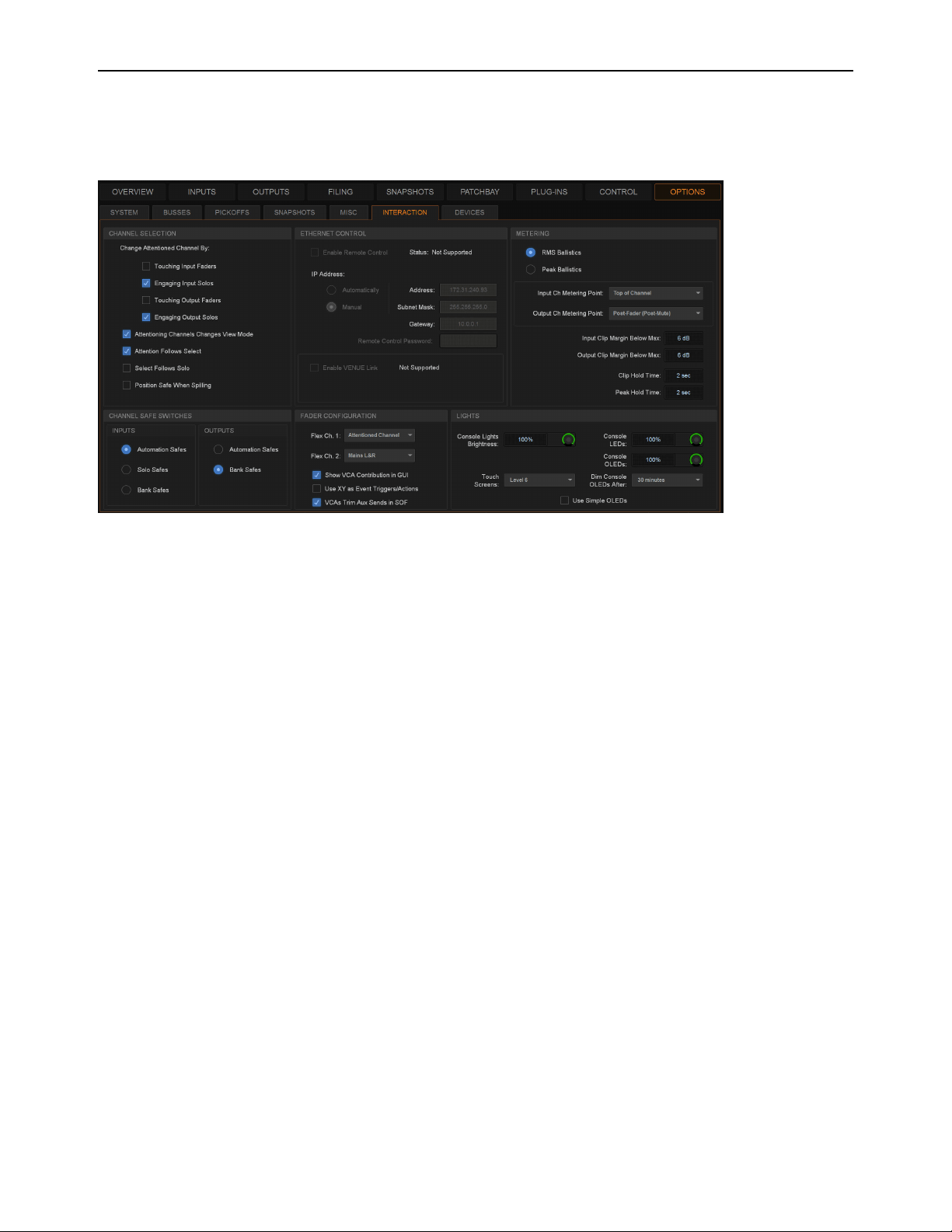
Options 342
Interaction
The Interaction tab lets you configure behaviors for attentioned and selected channels the Channel Safe Switches; light bar, OLED
and touch screen brightness; Metering; Ethernet Control and VENUE Link network settings; and Flex Channels and VCA config-
uration.
Channel Selection
Options in this section determine how channels are attentioned on the external screen and the MTS.
To customize control surface and screen interaction:
1 Go to the Options page and select the Interaction tab.
2 Set the following Channel Selection options:
Change Attentioned Channel By
Let you specify how a channel is attentioned on the external screen and the MTS. Select any or
all of the following options:
• Touching Input Faders
• Engaging Input Solos
• Touching Output Faders
• Engaging Output Solos
Attentioning Changes View Mode
When selected, updates the on-screen display to show the page for the currently attentioned
channel. When this option is deselected, the on-screen display does not update when a channel is targeted.
Attention Follows Select
When selected, any channel that is selected using the channel strip Select switch is also attentioned,
and is the default setting. When deselected, select and attention are decoupled.
Select Follows Solo
When selected, engaging Solo on any channel that is currently banked to the faders also selects that channel.
Solo can be engaged from the CFM, MTS, or external screen, but the channel must already be banked to the control surface to en-
gage local Select.
Position Safe When Spilling
When enabled, spilling a VCA, Aux, Group, or Matrix leaves the “master” (the channel from which
you initiated spill) in place on the surface, and spilled channels spill around the master. In effect, a “Spill Safe” state for the VCA,
Aux, Group, or Matrix. You can unspill by pressing Attention on that master strip. When not enabled, spilling a VCA, Aux, Group,
or Matrix replaces channels on as many strips as needed for the spill, except for any Bank Safed strips.
Interaction tab of the Options page (S6L-32D/24D)

Options 343
Meters Follow Selection (S6L-24C Only)
When the MTS is in Meters View it shows the channels on the faders directly below it
(OLEDs on those strips show a Selection outline). By default, Meters view on the 24C follows the Selected channel. You can
change this behavior to instead have the MTS Meters view be associated with whichever strips are banked below the MTS. This
setting is only available when using an S6L-24C control surface.
• When enabled, Meters View on the S6L-24C MTS associates with the bank of channels that has a channel selected locally.
• When not enabled, Meters View associates with the faders directly below the MTS.
Ethernet Control
Ethernet Control settings let you configure the following:
ECx Network Settings
These settings let you configure ECx Ethernet Control to remotely control of your system over a wired or
wireless Ethernet network. See the ECx Ethernet Control Guide for more information.
VENUE Link Settings
These settings let you configure VENUE Link to integrate a Pro Tools system with VENUE. For more in-
formation, see the S6L Live Recording Guide.pdf.
Metering
The following display options can be configured for meters. These options affect the 16 channel meters on the S6L control surface
and on-screen.
Meter Ballistics
This option lets you choose RMS or Peak ballistics for the control surface and on-screen meters.
RMS Ballistics
(Default) Meters follow the characteristics of a damped analog meter. In this mode, meter response and decay is
slower than in Peak mode, providing an average reading of the metered signal. A single LED shows the peak level for the desig-
nated Peak Hold Time.
Peak Ballistics
Meters follow the characteristics of a standard peak meter. In this mode, meter response is instantaneous, showing
the true peak level of the metered signal.
Metering Points
These options let you choose the point in the signal path where the signal is picked off for metering input and output channels.
Input Channels Metering Point
Choose one of the following options to set the input channel metering point:
• Top of Channel
•Insert Return
• Post-Fader (Post-Mute)
Output Channels Metering Point
Choose one of the following options to set the output channel metering point:
• Top of Channel
• Post-Fader (Post-Mute)
Meters Follow Selection setting in Options > Interaction on S6L-24C (only)
You can set Pro Tools metering to mirror VENUE metering.
Pro Tools Recording and Playback

Options 344
Clipping Indication
VENUE meter clip indicators are proximity warnings that show when an input or output signal reaches or exceeds the configured
Clip Margin.
Clipping can occur at several points throughout the signal chain. A clip at any one of these points is indicated by lighting the top
LED red on the meter. For more information on the location of clip detect points, refer to Chapter 26, “Signal Flow Diagrams.”
Clip Margin
Lets you configure the amount of headroom you want before clipping indication begins. Clip Margin is expressed as
dB below maximum (where maximum is a peak level of +20 dB VU).
Clip Margin can be set within a range of 0 dB to 30 dB below maximum, and is configured separately for inputs and outputs.
To set the Clip Margin:
1 Go to Options > Interaction.
2 Under Meter, enter values for Input Clip Margin Below Max and Output Clip Margin Below Max.
3 Press Enter to confirm the setting.
Clip Hold Time
The Clip Hold Time determines how long a clip indication lasts after the last clipped signal. Clip Hold Time can be set within a
range of 0–20 seconds.
To set the Clip Hold Time:
1 Go to Options > Interaction.
2 Under Meter, enter a value for the Clip Hold Time.
3 Press Enter to confirm the setting.
Channel Safe Switches
These options set the global Safe Mode that is enabled when you press a Channel Safe switch on the control surface, or select the
Channel Safe button on an external screen Inputs/Outputs page, and can be set to one of the following modes:
Automation Safes
Lets you suspend the effect of snapshots on all parameters of the channel. See Automation Safing Channels.
Solo Safes (Input Channels Only)
Prevents that channel from being implicitly muted when any other channel is soloed. See So-
loing Channels.
Bank Safes
Temporarily “locks” the location of key channels (such as a lead vocal or the Mains) on an S6L control surface chan-
nel strip. See Bank Safing Channels.
Fader Configuration
Configuring Flex Channels
The Flex Ch.1 and Flex Ch.2 pop-up menus provide the following options for each Flex Channel:
Mains L&R
Assigns the Mains L-R output to the Flex Channel, and is the default setting for Flex Channel 2. If the Mains L-R are
unlinked, you can target each Mains L and R bus individually on the Flex Channel by pressing the Attention switch on the corre-
sponding Flex Channel. The currently targeted Mains bus is indicated in the corresponding display. Solo is inoperable for Mains
when they are assigned to the Flex Channel.
Mains C/Mono
Assigns the C/Mono output to the Flex Channel. Solo is inoperable for Mains.
Monitor Bus A
Assigns level control for Monitor Bus A to the Flex Channel. This can be useful for monitor mixing workflows.
Monitor Bus B
Assigns level control for Monitor Bus B to the Flex Channel.
You can use Events to program a Function switch or other trigger to cycle through Input and Output Safe Switch modes. For
more information see
Events.
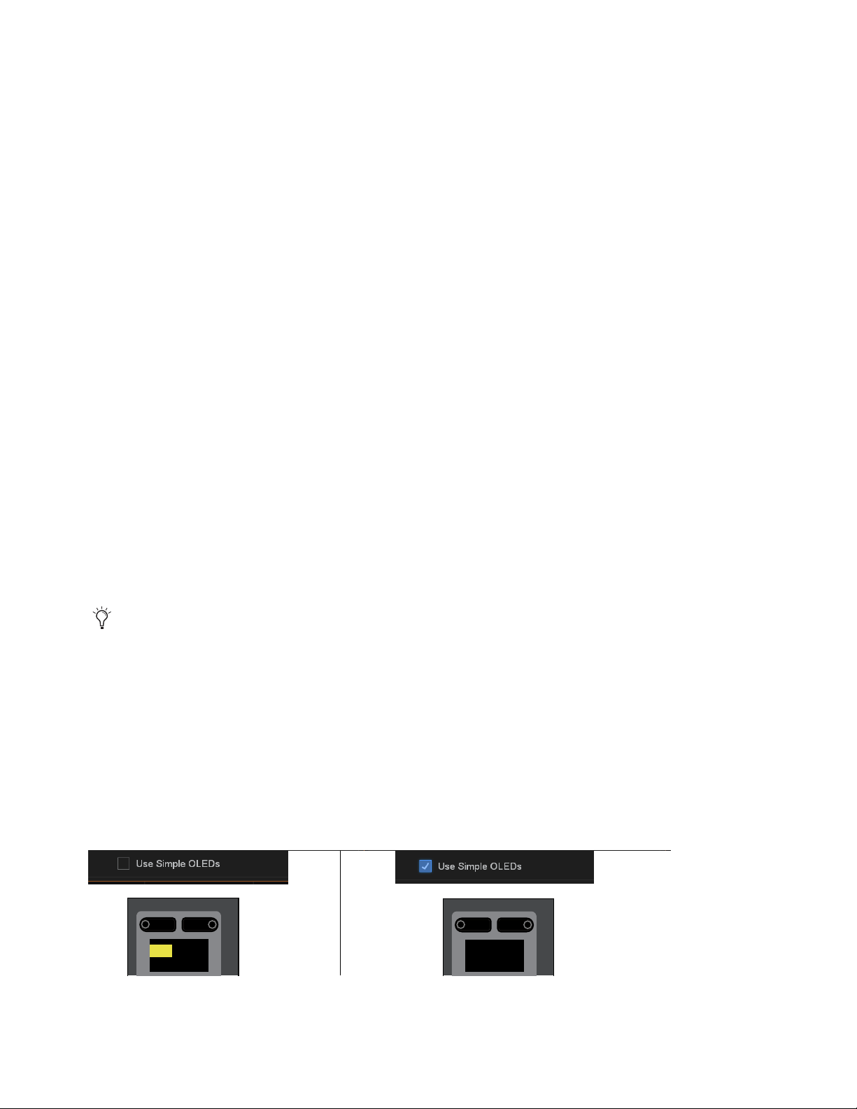
Options 345
Attentioned Channels
Assigns the currently attentioned channel to the Flex Channel, and is the default setting for Flex Channel 1.
Double-pressing a channel strip Attention strip “latches” that channel to the Flex Channel, until it is unlatched by another double
press.
Show VCA Contribution
This option lets you display a secondary, transparent fader cap on each on-screen fader strip that represents the effective channel
gain (channel gain plus associated VCA gain, if any). For more information, see Working with VCAs.
Use XY as Event Triggers/Actions
This option lets you reconfigure the channel X and Y switches to become available Triggers and Actions for Events. In their default
configuration, the X and Y switches in each channel strip toggle the corresponding Expander/Gate and Compressor/Limiter on/off,
respectively. When this option is enabled, the channel X and Y switches become available in the Switch (Type) list in the Trigger
properties Control Surface sub-menu and will no longer toggle their corresponding dynamics processor on/off, even if they are not
yet included in the definition of any specific Event.
VCAs Trim Aux Sends in SOF
This option lets you use VCAs to trim Aux send levels. By default this option is enabled. For more information, see VCAs Trim
Aux Sends in Sends on Faders Mode.
Lights
Console and LED/Display settings let you adjust the brightness of the following items:
Lightbar Brightness (S6L-32D/24D)
Adjusts the brightness of the built-in lightbar
Console Lamp Brightness (S6L-24C/16C)
Adjusts the brightness of any console lamps connected to the top-panel lamp con-
nectors.
Lightbar Color
Adjusts the color of the built-in lightbar.
Dim Consoles OLEDs After
Automatically dims the OLED displays on the control surface after the interval selected in the
pop-up menu.
Touch Screens
Adjusts the brightness of the MTS and any CTMs.
Consoles LEDs
Adjusts the brightness of the switch and encoder LEDs on the control surface.
Consoles OLEDs
Adjusts the brightness of the OLED displays on the control surface.
Use Simple OLEDs
Optimizes channel strip displays for easier viewing of channel name.
• When enabled, channel strip displays show channel Name, as well as Attention, Select, Sends on Faders and Flip status but
do not show channel numbers, hardware assignment, or level. When a fader is touched or moved, the fader value is displayed
under the channel name for as long as the fader is touched or in motion. The display of fader value times out after two seconds
of not being touched or moved. (Value is never shown when in Sends on Faders mode or Flip modes).
• When not enabled, channel strip displays show the complete set of channel information.
Touch any control on the control surface to undim the displays.
Channel display with Use Simple OLEDs disabled (at left) and enabled (at right)
Menu Safe
KICK2OT
CH2
0.0 dBS1AO2
Menu Safe
Kick 2 OUT

Options 346
Devices
The Devices tab lets you view and edit system connections, edit hardware settings, provides troubleshooting and diagnostic op-
tions, and provides network information.
1 – Engine
This section shows the E6L engine that is currently paired to the S6L control surface (and any other E6L engines detected on the
network). The current sample rate and word clock status (internal or external) is shown.
2 – HDX DSP
This section shows the DSP usage of the HDX TDM Mix Engine cards currently installed in the E6L engine.
To view a card’s DSP usage:
Select a card number 1–4 to view that card’s DSP usage.
3 – Network
This section shows the devices currently connected to the AVB audio network, and cards currently installed in the E6L engine.
Network Cards
This section shows the three AVB-192 Network card slots in the E6L engine, and the AVB-192 Network cards that are currently
installed in them. You can manage and view the devices that are connected to each card, and give each AVB-192 Network card a
unique name.
To view and manage the devices connected to an AVB-192 Network card:
Select a Network card. Devices available for connection are shown in the Available Devices column, and currently connected
devices are shown in the Connected Devices column. For example, select Ring 1 to see control surface and Stage I/O devices.
Select Ring 2 to see Local 16s (if any)
To rename an AVB-192 Network card:
Double-tap a Network card, then enter a name.
Devices tab of the Options page
1
2 3
4

Options 347
Available Devices
This section shows the devices that are available to be connected to the selected Network card. A device is dimmed if that device
has already been assigned via another AVB-192 Network card in the currently paired E6L engine. Available Stage I/O devices are
assigned using the
CONNECT button.
To connect a device:
1 Enable Config mode.
2 In the Available Devices list, select a device.
3 Select the Connect button at the bottom of the Available Devices column.
4 In the Connected Devices column, select a flashing Stage slot to assign that device to that Stage slot.
Connected Devices
This section shows the devices that are currently connected to the selected Network card in the Network Cards section. Assigned
Stage I/O devices are unassigned using the DISCONNECT button.
To unassign (disconnect) a device:
1 Enable Config mode.
2 In the Connected Devices column, select the Stage I/O device you want to unassign so it is outlined in blue.
3 Select the Disconnect button at the bottom of the Connected Devices column.
4 – Information
This section shows information for the device that is currently selected in the Devices page, as follows:
DEVICE
Shows the device type, the assigned name (which can be changed), MAC address(es), IP address, and device firrmware
versions (where applicable).
SETTINGS
Shows device settings for the E6L engine and Stage I/O devices as follows:
• For E6L, the current sample rate is shown.
• For Stage 64 and Stage 32, shows the I/O cards currently installed in each slot. You can also set MADI Out sample rate (see
Configuring Stage 64 and Stage 32 MADI Outs), and enable DSI-192 card ADAT inputs (see Enabling ADAT Inputs).
Status
Provides hardware monitoring information, such as internal temperature and voltage.
To rename a device:
1 Select a device on the Devices page.
2 Select the DEVICE tab.
3 Double-tap the Name field, and enter a new name.
Device names are stored with the device (they are not saved or included in Show files). Custom names for Stage units are dis-
played in the Patchbay.
Configuring Stage 32 Settings
Unlike Stage 64 and Stage 16, Stage 32 slots can be used for input or output cards. The only restriction is that all input cards must
be installed in lower-lettered slots and physically above output cards. For example, in a base configuration Stage 32 the three input
cards are in slots A, B, and C, while one output card is in Slot D.
If your Stage 32 includes one or two DNT-192 Dante Network cards, configure the Stage 32 and each Dante card in the
Devices
tab for 16-in or 16-out operation. Note that if any output card (SRO-192 or DSO-192) is installed in a lower-lettered slot the
DNT-192 will auto-configure to 16 channels of output (this cannot be changed). If input cards (or another DNT-192 card) are in
lower-lettered slots, do the following to configure the DNT-192 card.
For additional information and requirements, see
Managing Stage I/O Unit Connections.
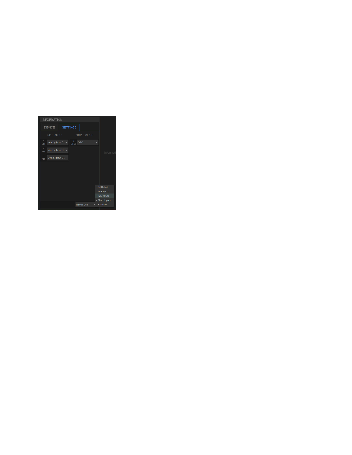
Options 348
To configure Stage 32 DNT-192 Dante I/O:
1 Make sure the system is in Config mode.
2 Select the Stage 32 in the AVAILABLE DEVICES column. If the Stage 32 is listed in the CONNECTED column, select it and
choose DISCONNECT to make it available in the AVAILABLE column.
3 In the INFORMATION section display the SETTINGS tab.
4 Use the selector at the bottom of the SETTINGS tab to configure the Stage 32 for the desired input/output arrangement (All Out-
puts, One Input, Two Inputs, Three Inputs, or All Inputs).
For example, in its base configuration Stage 32 includes three input cards and one output card. If you have removed the input and
output cards in slots C–D and replaced them with a single DNT-192 Dante card which you want to use for 16 channels of Dante
output, select
Two inputs.
5 In the OUTPUT SLOTS column that appears, use the selector for port C to choose Dante Output Card.
Slots C and D populate with Dante Output Card channels (1–8, and 9–16). To use this same Dante card for 16 channels of Dante
input, repeat the above steps but configure the Stage 32 for All Inputs, then select Dante Input Card for (Input) slot C.
Managing I/O from the Devices Page
You can identify connected Stage I/O devices and mute Stage and S6L control surface outputs from the Devices page.
Identifying Stage I/O Devices
The Identify button on an on-screen Stage device icon lets you identify the corresponding physical Stage unit.
To identify a connected Stage 64:
1 Select a Stage I/O unit on the Devices page.
2 Select the DEVICE tab.
3 Select the Identify button to latch the button on. The Identify button on-screen flashes, and the Power and Status LEDs on the
front panel of the corresponding Stage unit flash.
Configuring Stage 32 I/O in Options > Devices, Settings tab

Options 349
Muting Stage and S6L Control Surface Outputs
The Mute button on the Devices tab lets you mute all the outputs on connected Stage I/O units or the S6L control surface.
To mute the outputs of a Stage unit or S6L control surface:
1 Select a device on the Devices page.
2 Select the DEVICE tab.
3 Select MUTE. The Mute switch flashes while the outputs are muted, and the Mute LEDs on the Stage units or the S6L control
surface light solid red.
When engaging Global Mute on systems configured for I/O sharing:
• If only one E6L engine has claimed the Output slots in the selected Stage unit, all Outputs on the selected device are muted.
• If more than one E6L engine has ownership of Output slots in the selected Stage unit, the following dialog appears:
MUTE <Stage number>
MUTING this stage device will Mute outputs claimed by another E6L engine <user defined name>, are you sure you want
to MUTE this device?
Select OK to proceed and mute all outputs. Or select Cancel to cancel without affecting any outputs.
When a Stage 64 is muted manually from the Stage 64 front panel, all outputs are immediately muted and no confirmation dialog
or choices are presented.
AVB Network Card Port A and B LEDs
On-screen LEDs are provided on the Devices page to indicate the status of the physical A and B Network ports on each S6L system
component (S6L control surface, E6L engine, and Stage I/O units), as follows:
Plug-Ins
The Plug-Ins tab of the Options page is used to install plug-ins on the system. The Plug-Ins tab is not available in the VENUE
Standalone software.
LED Color Network Port Status
Green The port is connected and has a valid connection to another device.
Amber This port is connected and is part of a non-redundant daisy-chain.
Red flashing The port has lost a connection with a device. When canceled via dialog box, it turns off.
Off This port does not have a connection with a device. For example, it is a device at the end of a non-redundant daisy-chain.
See
Installing and Authorizing Plug-Ins.

Part IV: Recording and Playback

Pro Tools Recording and Playback 351
Pro Tools Recording and Playback
VENUE | S6L systems provide direct connection to up to two computers running Pro Tools software via AVB Ethernet. The Ether-
net AVB connection between your S6L system and Pro Tools provides up to 128 channels of simultaneous Pro Tools I/O. No ad-
ditional audio hardware is required to connect your S6L system to Pro Tools.
• This single Ethernet connection lets you record multi-track Pro Tools sessions of performances using a variety of S6L system
audio sources, including digital splits of your Stage inputs, channel Direct Outputs, and bus outputs.
• You can also play back multi-track audio from Pro Tools through your S6L system to integrate pre-recorded tracks with your
live mix, or to monitor your Pro Tools recording on your S6L system. When VENUE Link is enabled, the same connection
also lets you control the Pro Tools Transport from the S6L control surface.
• By combining recording and playback features, you can perform a true Virtual Soundcheck. Play back the tracks from a pre-
vious performance, adjust the mix, and have the changes remain when you switch back to your live mix.
You can connect up to two Pro Tools systems, using S6L control surface Network ports
C and D for fully redundant recording and
Virtual Soundcheck:
Redundant Recording
On both Pro Tools systems, enable VENUE Link and use Create Session from VENUE to be able to re-
cord your performance to both Pro Tools systems simultaneously (fully redundant recording of up to 128 tracks). By enabling
VENUE Link on both systems, both Pro Tools systems respond as one to Transport commands from S6L.
Virtual Soundcheck
When you switch the S6L system Input Source to Pro Tools to perform a Virtual Soundcheck, playback will
be available from the Pro Tools computer that was connected to the E6L engine last in AMS. When VENUE Link is enabled on
both Pro Tools systems they will both play back and cue in response to Transport commands from S6L, but audio from the
first-connected Pro Tools system will not be available (only audio from the last-connected Pro Tools system is recognized by S6L).
Simultaneous Record/Playback
If you need to simultaneously record to and play back from Pro Tools to integrate backing
tracks, count-offs or other material, use a single Pro Tools system connected to S6L Network port C, only.
For complete instructions on integrating Pro Tools recording and playback with your S6L system see the S6L Live Recording
Guide.pdf, available for download from your
Avid account and from the S6L Documentation article on our Knowledge Base.
Pro Tools Compatibility
Avid can only assure compatibility and provide support for hardware and software it has tested and approved.
For complete system requirements and a list of qualified versions of Pro Tools software, computers, operating systems, hard drives,
and third-party devices, visit:
www.avid.com/S6Lsupport
Important Requirements and Optimizations for a Mac with Pro Tools AVB
Make sure your AVB-compatible Mac and other equipment is qualified to support 128 Channel AVB with Pro Tools. For complete
compatibility requirements and optimization recommendations, see System Requirements for Pro Tools with S6L.
Do the following to optimize your Mac for 64- or 128-channel AVB recording and playback:
• Disable Wi-Fi, Airport, and Blue Tooth, and turn off Internet Sharing
• Disable Blue Tooth
• Turn off Energy Saving
• Disable Notification Center

Part V: Reference

Synchronization 353
Synchronization
This section describes how to synchronize S6L with external digital devices, and how to incorporate time code in your perfor-
mances.
Clock Synchronization Overview
Whenever two digital audio devices are connected together, care must be taken to ensure they are properly synchronized or the au-
dio will suffer from clicks, pops and distortion (even if the devices are operating at the same sample rate).
In simple configurations where you are synchronizing a single external device with a single S6L system, the device providing
source audio can serve as the master clock source, or the S6L system serve as the master clock source. In this type of simple con-
figuration you can use word clock, or you can synchronize your external device to the AES, ADAT, or MADI stream coming from
the S6L system.
In configurations where more than two digital devices are being connected, distributed word clock should always be used. In these
types of more complex configurations, use dedicated, “distributed” word clock connections from the master (or “house”) clock
source to each device.
S6L clock synchronization capabilities include the following:
Word Clock
You can sync external digital devices to your S6L system or sync your VENUE system to external digital devices,
such as a master (or “house”) clock or another digital console, using word clock. For instructions, see
Synchronizing External De-
vices using Word Clock.
Digital Audio (AES/ADAT, or MADI)
S6L AES/ADAT and MADI outputs can be used as the clock source for compatible external
devices (the external device must support syncing to these types of signals).
• You can utilize AES/ADAT clocking to sync external devices to S6L AES/ADAT outputs from the S6L control surface or Lo-
cal 16, or from DSI-192 Option cards, if any, installed in Stage 64 or Stage 32. See Synchronizing using AES/ADAT or
MADI Clock.
• You can utilize MADI clocking to sync external devices to MADI outputs from Stage 64 or Stage 32, or from MADI-192 Op-
tion cards (if any). MADI clocking requires high-quality MADI cables and other additional guidelines, especially in I/O Shar-
ing configurations. See Using MADI Audio to Synchronize a Single External MADI Device to S6L.
For best performance, or if in doubt about the capabilities of your external devices, use word clock to synchronize S6L with exter-
nal digital devices.
Time Code Overview
S6L also provides a set of synchronization features that allow automation and remote control of snapshots and triggering of external
devices when snapshots are recalled via SMPTE MIDI Time Code (MTC) or Linear Time Code (LTC). For more information, see
Time Code.
Do not “daisy-chain” word clock among multiple devices. Use a distributed word clock configuration.
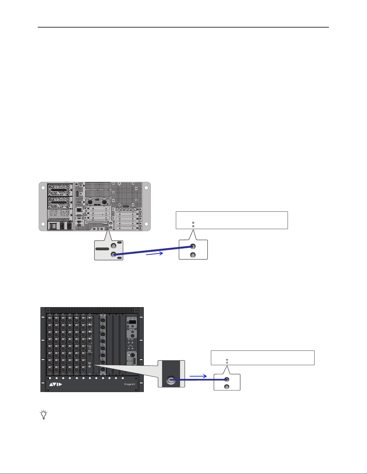
Synchronization 354
Synchronizing External Devices using Word Clock
You can sync external digital devices to your S6L system, or sync your S6L system to external digital devices, using word clock.
Syncing External Devices to an S6L System using Word Clock
You can use either the E6L Word Clock Out, or a DSI-192 Word Clock Out (if your system includes any DSI-192 cards) to supply
word clock to external devices. When doing so, always observe the following guidelines:
• When using a single S6L system (non-I/O Sharing) never connect more than one S6L component Word Clock Out port to ex-
ternal devices. If you need to sync multiple external devices to S6L, use a distributed word clock source (do not daisy-chain).
See Using a Distributed External Master Clock to Synchronize Multiple Devices.
• The external device must be configured to sync to the word clock signal from S6L.
• If your system includes one or more MADI-192 MADI Option cards, never connect their
Word Clock Out ports.
• When multiple S6L systems are configured for I/O sharing, see
Important: Synchronization in Shared I/O Configura-
tions.
E6L Word Clock Out
Connect a coaxial cable from the Word Clock Out on the E6L engine back panel to the word clock input on the external device.
Set the external device to sync to the word clock signal coming from the VENUE system.
DSI-192 Word Clock Out
If your system includes a DSI-192 card, connect a coaxial cable from the Word Clock Out port on the card to the word clock
input on the external device. Set the external device to sync to the word clock signal coming from the VENUE system.
External device connected and configured to sync to incoming word clock, supplied by E6L Word Clock Out
External device connected and configured to sync to incoming word clock, supplied by DSI-192 Word Clock Out
At the time of this writing the built-in Stage 64 Word Clock connectors are not supported. Use the Word Clock Out on the
DSI-192 only.
IN
OUT
NETWORK
MASTER 1
WORD CLOCK
UTIL
EXPANSION
2
3
6
7
8
1
2
3
4
5
OKOK
A
B
AVB-192
ACT SIG ACT SIG
ACT SIG ACT SIG
A
B
IN
OUT
WORD CLOCK
MADI-192
SRC
IN OUT IN WC OUTOUT
WORD CLOCK
WORD CLOCK
IN
IN
OUT
OUT
External Device
Sync to: WC IN
ABCD E FGH JKLM
1
2
3
4
5
6
7
8
SIG +48V
SIG +48V
SIG +48V
SIG +48V
SIG +48V
SIG +48V
SIG +48V
SIG +48V
INPUT
SRI-192
1
2
3
4
5
6
7
8
SIG +48V
SIG +48V
SIG +48V
SIG +48V
SIG +48V
SIG +48V
SIG +48V
SIG +48V
INPUT
SRI-192
1
2
3
4
5
6
7
8
SIG +48V
SIG +48V
SIG +48V
SIG +48V
SIG +48V
SIG +48V
SIG +48V
SIG +48V
INPUT
SRI-192
1
2
3
4
5
6
7
8
SIG +48V
SIG +48V
SIG +48V
SIG +48V
SIG +48V
SIG +48V
SIG +48V
SIG +48V
INPUT
SRI-192
1
2
3
4
5
6
7
8
SIG +48V
SIG +48V
SIG +48V
SIG +48V
SIG +48V
SIG +48V
SIG +48V
SIG +48V
INPUT
SRI-192
1
2
3
4
5
6
7
8
SIG +48V
SIG +48V
SIG +48V
SIG +48V
SIG +48V
SIG +48V
SIG +48V
SIG +48V
INPUT
SRI-192
SIG MUTE
MUTE
MUTE
MUTE
MUTE
MUTE
MUTE
MUTE
SIG
SIG
SIG
SIG
SIG
SIG
SIG
OUTPUT
SRO-192
1
2
3
4
5
6
7
8
INPUT
DSI-192
OUT
WORD
CLOCK
WORD CLOCK
WORD CLOCK
IN
IN
OUT
OUT
External Device
Sync to: WC IN
DSI-192
Option Card
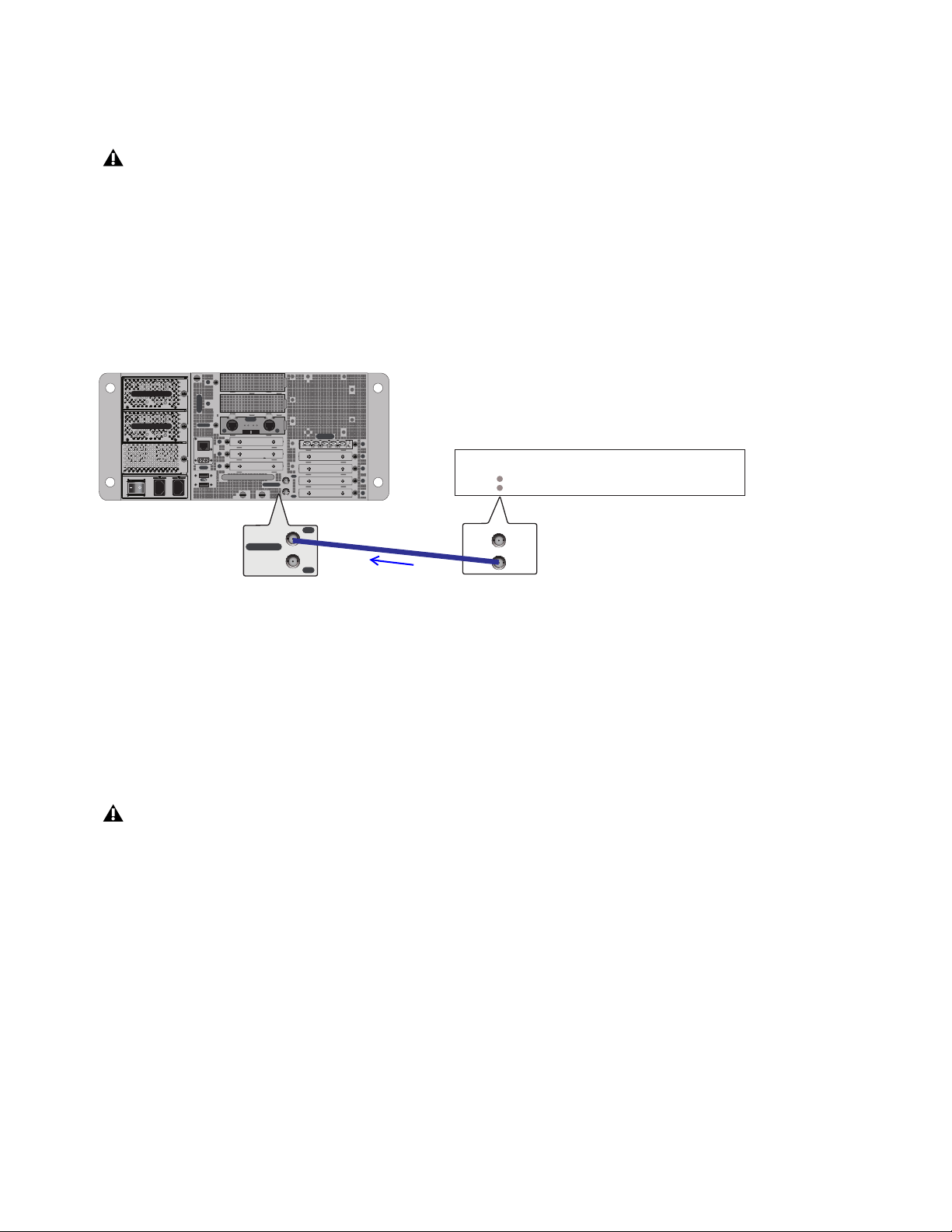
Synchronization 355
Syncing an S6L System to an External Device using Word Clock
The S6L system automatically syncs to external word clock when connected to an external device sending a valid word clock sig-
nal. If the external word clock signal is interrupted, the S6L system defaults back to its internal word clock.
To sync the S6L system to an external device using word clock:
1 Make sure the outgoing word clock rate of the external device is set to match your VENUE system word clock rate.
2 Connect a coaxial cable from the word clock out port on the external device to the Word Clock In port on the E6L engine.
When a valid word clock connection is recognized by the S6L system EXT is indicated in the Status box, and WC Ext also ap-
pears next to the graphic of the currently paired E6L engine on the external screen Options > Devices page. That E6L becomes
the S6L Media Clock Master.
Important: Synchronization in Shared I/O Configurations
E6Ls in shared I/O configurations can send and receive word clock, letting you sync external devices to your networked S6L sys-
tem. However, only one E6L engine should ever be connected to an external word clock device.
I/O sharing configurations should be thought of as a single “system” in terms of clock. When you connect two E6L engines together
(where two S6L systems are sharing one or more Stage I/O units in a shared I/O configuration), only one of the E6L engines should
ever be connected to an external word clock device. This E6L engine then becomes the Master clock for the entire dual-system con-
figuration and distributes clock to all other S6L devices. If no external word clock device is connected, the E6L that comes online
first becomes the Master clock for the entire system.
See the following two sections for instructions and examples:
•
Syncing an External Device to S6L Word Clock when Configured for I/O Sharing
• Syncing S6L to External Word Clock when Configured for I/O Sharing
Only the E6L Word Clock In port should ever be connected to an external word clock source. Never use the Word Clock In port
on the Stage 64. If utilizing I/O sharing, be sure to follow the guidelines explained in Important: Synchronization in Shared
I/O Configurations.
External device connected and configured to provide word clock to S6L via the E6L Word Clock In
Never connect word clock from one engine to the other when sharing I/O, and always make sure that only one E6L engine's word
clock input is connected if using an external word clock when sharing I/O.
IN
OUT
NETWORK
MASTER 1
WORD CLOCK
UTIL
EXPANSION
2
3
6
7
8
1
2
3
4
5
OKOK
A
B
AVB-192
ACT SIG ACT SIG
ACT SIG ACT SIG
A
B
IN
OUT
WORD CLOCK
MADI-192
SRC
IN OUT IN WC OUTOUT
WORD CLOCK
WORD CLOCK
IN
IN
OUT
OUT
External Device
WC rate set to match VENUE
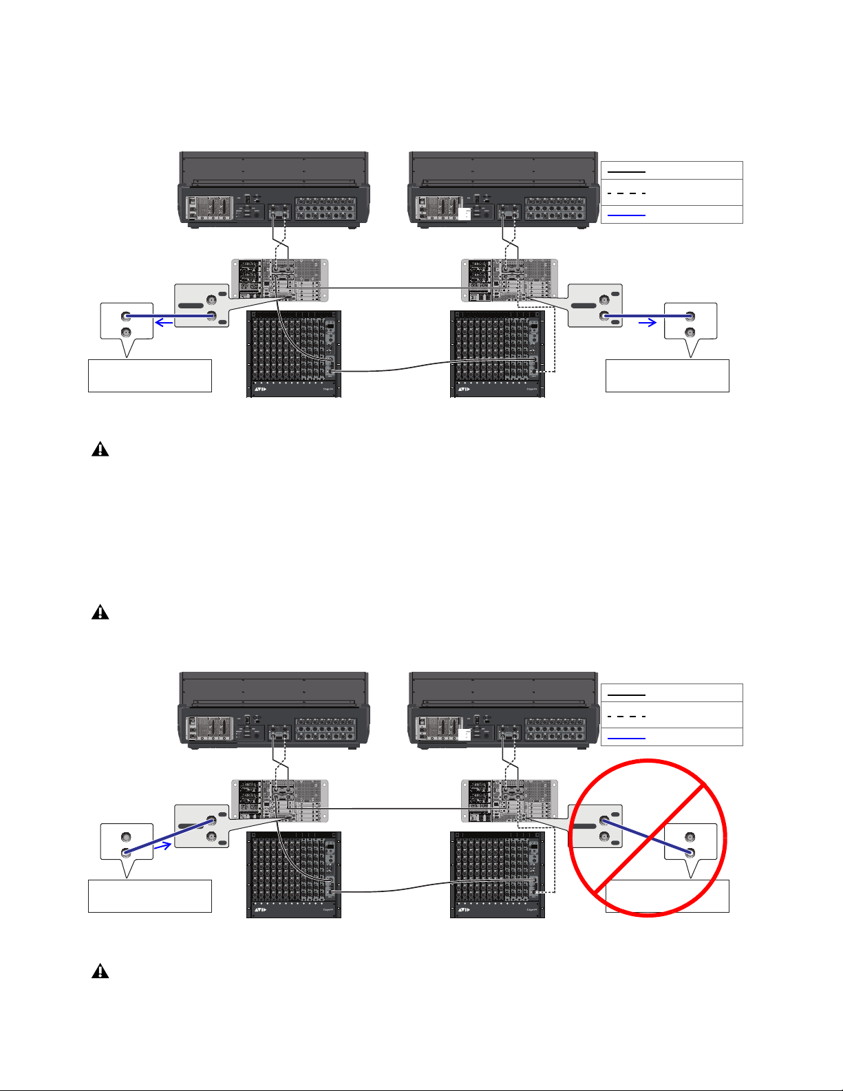
Synchronization 356
Syncing an External Device to S6L Word Clock when Configured for I/O Sharing
To sync an external device to S6L when configured for I/O sharing:
Connect a BNC cable from a Word Clock Out port on one or both E6L engines on the network to the external device(s).
Syncing S6L to External Word Clock when Configured for I/O Sharing
To sync S6L to an external device when configured for I/O Sharing:
Connect a BNC cable from the external device to a Word Clock In port on either (one) of the E6L engines on the network.
When the E6L to which the external device is connected detects a valid word clock signal, EXT is indicated in its Status box and
that E6L is automatically designated as the S6L Media Clock Master. When your S6L system is synced to an external device, the
E6L designated as the Media Clock Master cannot be changed.
Connecting Word Clock Out from both E6L engines when configured for I/O Sharing
At the time of this writing, the WC Out port on the MADI-192 MADI Option card (if any) is not supported and should not be used.
Never connect word clock from one engine to the other when sharing I/O, and always make sure that only one E6L engine's word
clock input is connected if using an external word clock when sharing I/O.
Connecting word clock output from an external device to an E6L Word Clock In (connect to either single engine, but never both)
At the time of this writing, the Word Clock In port on the Stage 64 is not supported and should not be used.
IN
OUT
NETWORK
MASTER 1
WORD CLOCK
UTIL
EXPANSION
2
3
6
7
8
1
2
3
4
5
OKOK
A
B
AVB-192
ACT SIG ACT SIG
ACT SIG ACT SIG
A
B
A
B
A
B
IN
OUT
NETWORK
MASTER 1
WORD CLOCK
UTIL
EXPANSION
2
3
6
7
8
1
2
3
4
5
OKOK
A
B
AVB-192
ACT SIG ACT SIG
ACT SIG ACT SIG
A
B
ABCD EFGHJKLM
1
2
3
4
5
6
7
8
SIG +48V
SIG +48V
SIG +48V
SIG +48V
SIG +48V
SIG +48V
SIG +48V
SIG +48V
INPUT
SRI-192
1
2
3
4
5
6
7
8
SIG +48V
SIG +48V
SIG +48V
SIG +48V
SIG +48V
SIG +48V
SIG +48V
SIG +48V
INPUT
SRI-192
1
2
3
4
5
6
7
8
SIG +48V
SIG +48V
SIG +48V
SIG +48V
SIG +48V
SIG +48V
SIG +48V
SIG +48V
INPUT
SRI-192
1
2
3
4
5
6
7
8
SIG +48V
SIG +48V
SIG +48V
SIG +48V
SIG +48V
SIG +48V
SIG +48V
SIG +48V
INPUT
SRI-192
1
2
3
4
5
6
7
8
SIG +48V
SIG +48V
SIG +48V
SIG +48V
SIG +48V
SIG +48V
SIG +48V
SIG +48V
INPUT
SRI-192
1
2
3
4
5
6
7
8
SIG +48V
SIG +48V
SIG +48V
SIG +48V
SIG +48V
SIG +48V
SIG +48V
SIG +48V
INPUT
SRI-192
SIG MUTE
MUTE
MUTE
MUTE
MUTE
MUTE
MUTE
MUTE
SIG
SIG
SIG
SIG
SIG
SIG
SIG
OUTPUT
SRO-192
1
2
3
4
5
6
7
8
1
2
3
4
5
6
7
8
SIG +48V
SIG +48V
SIG +48V
SIG +48V
SIG +48V
SIG +48V
SIG +48V
SIG +48V
INPUT
SRI-192
1
2
3
4
5
6
7
8
SIG +48V
SIG +48V
SIG +48V
SIG +48V
SIG +48V
SIG +48V
SIG +48V
SIG +48V
INPUT
SRI-192
SIG MUTE
MUTE
MUTE
MUTE
MUTE
MUTE
MUTE
MUTE
SIG
SIG
SIG
SIG
SIG
SIG
SIG
OUTPUT
SRO-192
1
2
3
4
5
6
7
8
SIG MUTE
MUTE
MUTE
MUTE
MUTE
MUTE
MUTE
MUTE
SIG
SIG
SIG
SIG
SIG
SIG
SIG
OUTPUT
SRO-192
1
2
3
4
5
6
7
8
SIG MUTE
MUTE
MUTE
MUTE
MUTE
MUTE
MUTE
MUTE
SIG
SIG
SIG
SIG
SIG
SIG
SIG
OUTPUT
SRO-192
1
2
3
4
5
6
7
8
AVB-192
ACT SIG ACT SIG
ACTSIG ACTSIG
A
B
AVB-192
ACT SIG ACT SIG
ACT SIG ACT SIG
A
B
WORD CLOCK
IN
OUT
External Device
WC rate set to match VENUE
IN
OUT
WORD CLOCK
WORD CLOCK
IN
OUT
External Device
WC rate set to match VENUE
IN
OUT
WORD CLOCK
Primary network
Redundant network
Word clock
(required)
IN
OUT
NETWORK
MASTER 1
WORD CLOCK
UTIL
EXPANSION
2
3
6
7
8
1
2
3
4
5
OKOK
A
B
AVB-192
ACT SIG ACT SIG
ACT SIG ACT SIG
A
B
A
B
A
B
IN
OUT
NETWORK
MASTER 1
WORD CLOCK
UTIL
EXPANSION
2
3
6
7
8
1
2
3
4
5
OKOK
A
B
AVB-192
ACT SIG ACT SIG
ACT SIG ACT SIG
A
B
ABCD EFGHJKLM
1
2
3
4
5
6
7
8
SIG +48V
SIG +48V
SIG +48V
SIG +48V
SIG +48V
SIG +48V
SIG +48V
SIG +48V
INPUT
SRI-192
1
2
3
4
5
6
7
8
SIG +48V
SIG +48V
SIG +48V
SIG +48V
SIG +48V
SIG +48V
SIG +48V
SIG +48V
INPUT
SRI-192
1
2
3
4
5
6
7
8
SIG +48V
SIG +48V
SIG +48V
SIG +48V
SIG +48V
SIG +48V
SIG +48V
SIG +48V
INPUT
SRI-192
1
2
3
4
5
6
7
8
SIG +48V
SIG +48V
SIG +48V
SIG +48V
SIG +48V
SIG +48V
SIG +48V
SIG +48V
INPUT
SRI-192
1
2
3
4
5
6
7
8
SIG +48V
SIG +48V
SIG +48V
SIG +48V
SIG +48V
SIG +48V
SIG +48V
SIG +48V
INPUT
SRI-192
1
2
3
4
5
6
7
8
SIG +48V
SIG +48V
SIG +48V
SIG +48V
SIG +48V
SIG +48V
SIG +48V
SIG +48V
INPUT
SRI-192
SIG MUTE
MUTE
MUTE
MUTE
MUTE
MUTE
MUTE
MUTE
SIG
SIG
SIG
SIG
SIG
SIG
SIG
OUTPUT
SRO-192
1
2
3
4
5
6
7
8
1
2
3
4
5
6
7
8
SIG +48V
SIG +48V
SIG +48V
SIG +48V
SIG +48V
SIG +48V
SIG +48V
SIG +48V
INPUT
SRI-192
1
2
3
4
5
6
7
8
SIG +48V
SIG +48V
SIG +48V
SIG +48V
SIG +48V
SIG +48V
SIG +48V
SIG +48V
INPUT
SRI-192
SIG MUTE
MUTE
MUTE
MUTE
MUTE
MUTE
MUTE
MUTE
SIG
SIG
SIG
SIG
SIG
SIG
SIG
OUTPUT
SRO-192
1
2
3
4
5
6
7
8
SIG MUTE
MUTE
MUTE
MUTE
MUTE
MUTE
MUTE
MUTE
SIG
SIG
SIG
SIG
SIG
SIG
SIG
OUTPUT
SRO-192
1
2
3
4
5
6
7
8
SIG MUTE
MUTE
MUTE
MUTE
MUTE
MUTE
MUTE
MUTE
SIG
SIG
SIG
SIG
SIG
SIG
SIG
OUTPUT
SRO-192
1
2
3
4
5
6
7
8
AVB-192
ACT SIG ACT SIG
ACTSIG ACTSIG
A
B
AVB-192
ACT SIG ACT SIG
ACT SIG ACT SIG
A
B
WORD CLOCK
IN
OUT
External Device
WC rate set to match VENUE
IN
OUT
WORD CLOCK
WORD CLOCK
IN
OUT
External Device
WC rate set to match VENUE
IN
OUT
WORD CLOCK
Primary network
Redundant network
Word clock
(required)
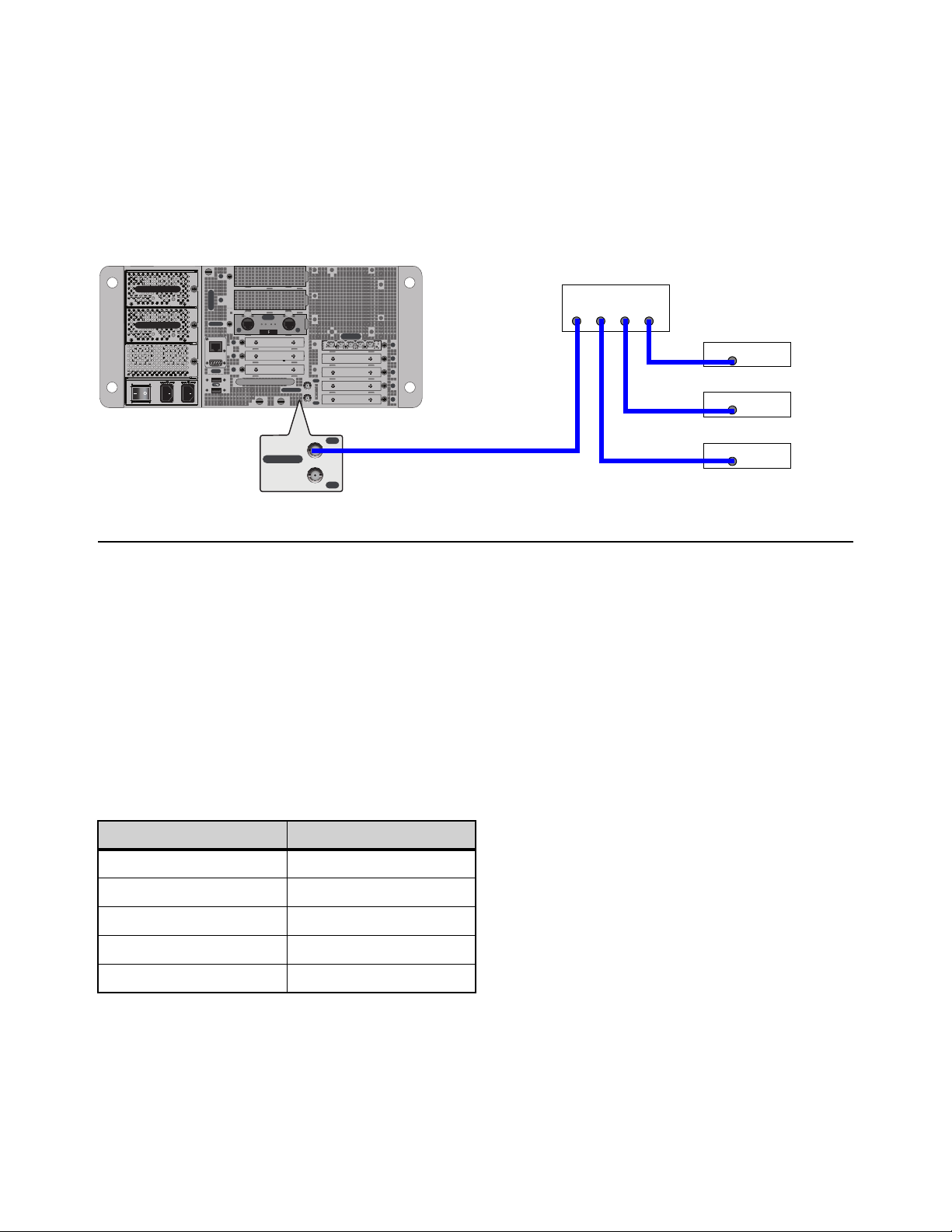
Synchronization 357
Using a Distributed External Master Clock to Synchronize Multiple Devices
When routing MADI or AES/ADAT audio between VENUE system(s) and multiple external devices, use a distributed external
master clock to provide a common word clock to each device.
In a distributed master clock configuration, a dedicated word clock connection is made from a master clock source (such as a clock
generator) to the VENUE system, and separate dedicated word clock connections are made from the master clock source to each
external device. All external devices must be set to a 96 kHz word clock rate.
You might have to configure the external devices to receive word clock. Check the device’s documentation.
Synchronizing using AES/ADAT or MADI Clock
S6L AES/ADAT and MADI outputs can be used as the clock source for compatible external devices (the external device must sup-
port syncing to these types of signals).
Synchronizing AES/ADAT Digital Audio Inputs (SRC)
The AES digital inputs on the S6L control surface and the DSI-192 card provide sample rate conversion on input, letting you con-
nect a wide variety of digital sources without having to be concerned with synchronization and clock connections. Sample rate con-
version does, however, induce processing delay to the incoming digital signal. (If the source device and S6L are already synchro-
nized via word clock then you can defeat SRC to minimize latency. )
Sample Rate Conversion Latency
The following table illustrates the sample rate conversion processing delay at various sample rates.
Distributed word clock
External Sample Rate SRC Process Delay
32 kHz 1.50 ms
44.1 kHz 1.09 ms
48 kHz 1.00 ms
88.2 kHz 0.848 ms
96 kHz 0.833 ms
IN
OUT
NETWORK
MASTER 1
WORD CLOCK
UTIL
EXPANSION
2
3
6
7
8
1
2
3
4
5
OKOK
A
B
AVB-192
ACT SIG ACT SIG
ACT SIG ACT SIG
A
B
IN
OUT
WORD CLOCK
MADI-192
SRC
IN OUT IN WC OUTOUT
Master clock generator
Digital device 1
Digital device 2
Digital device 3
Word Clock
OUT OUT OUT OUT
Word Clock
IN
Word Clock
IN
Word Clock
IN

Synchronization 358
Working with DSI-192 Digital Inputs
On systems that include a DSI-192 card, you can manually disable the SRC on AES input pairs, and you can designate the ADAT
optical port on the card as the active input source on the card on the external screen.
Defeating SRC on a DSI-192 Inputs
You can manually disable SRC on each DSI-192 AES input, or on all ADAT inputs to ensure the lowest possible latency.
To disabled SRC on a DSI-192 AES channel pair:
1 On the external screen, go to the Inputs page.
2 Attention the channel whose source is the DSI-192 input for which you
want to defeat SRC.
3 Select the SRC OFF button in the Input section so it lights (the same
LED on the DSI card lights to indicate SRC is disabled).
Enabling ADAT Inputs
You can designate the ADAT optical port as the active input source on the card. When ADAT inputs are enabled, AES inputs are
not operative. When SRC is enabled, at 48 kHz the ADAT inputs can receive eight channels of audio, 4 channels at 96 kHz, and
two channels at 192 kHz.
To enable ADAT inputs:
1 On the external screen, go to the Devices page.
2 Put the system into Config mode.
3 In the Connected Devices column, select the Stage 64 in which the DSI-192 card is installed so it is highlighted in blue.
4 In the Information section, select the Settings tab.
5 Next to the DSI card, select the AES/ADAT pop-up menu, and choose one
of the following options to enable ADAT inputs:
• ADAT 48K 8 ch
• ADAT 96K 4 ch
• ADAT 192k 2 ch
The ADAT source LED lights on the DSI-192 card. When the DSI-192 detects
a valid ADAT signal, the
Lock LED lights on the DSI-192 card.
SRC OFF button
DSI-192 card AES/ADAT pop-up menu
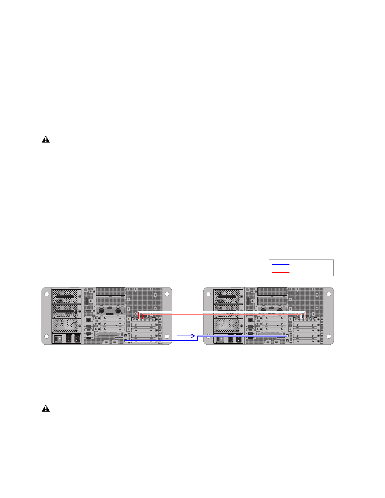
Synchronization 359
Synchronizing MADI Devices
Whenever two MADI devices are connected together, care must be taken to ensure they are properly synchronized or the audio will
suffer from clicks, pops and distortion (even if the devices are operating at the same sample rate).
• In simple configurations where you are clocking a single external device with a single S6L system, the device providing
source audio (whether S6L or the external device) can serve as the master word clock source.
• When two S6L systems are exchanging MADI, special word clock requirements apply.
• When sending MADI from S6L to an external MADI device, synchronization can also be achieved by configuring that exter-
nal device to clock to the incoming MADI signal.
• In configurations where more than two digital devices are being connected, distributed word clock should always be used. In
these types of more complex configurations, use dedicated, “distributed” word clock connections from the master (or
“house”) clock source to each device. For more information, see
Using a Distributed External Master Clock to Synchro-
nize Multiple Devices.
This section shows the following example configurations:
•
Using Word Clock to Synchronize Two VENUE Systems Exchanging MADI (Non-I/O Sharing)
• Synchronizing Two VENUE Systems Exchanging MADI in I/O Sharing Configurations
• Using MADI Audio to Synchronize a Single External MADI Device to S6L
Not all devices support all of these synchronization methods, so you should consult the user guide for your MADI device in order
to determine its capabilities.
Using Word Clock to Synchronize Two VENUE Systems Exchanging MADI (Non-I/O Sharing)
When using MADI to or from two VENUE S6L systems that are not configured for I/O Sharing, one of the systems must provide
word clock to the other system. Once connected, the S6L system receiving word clock detects it automatically.
Do not attempt to sync an S6L system to incoming MADI from another S6L system; use word clock instead.
To synchronize two discrete (non-I/O Sharing) VENUE systems:
Connect the coaxial cable from the WORD CLOCK OUT port on one of the VENUE S6L systems to the WORD CLOCK IN
port on the other VENUE system.
The VENUE system receiving word clock auto-detects word clock and displays EXT in the Mode box on-screen.
Do not “daisy-chain” word clock among multiple devices. Use a distributed word clock configuration.
Connecting Work Clock between two independent (not I/O Sharing) VENUE S6L systems exchanging MADI via MADI-192 MADI Option
Cards (E6L 1 Word Clock Out, at left, to E6L 2 Word Clock In, at right)
Never connect word clock from one engine to the other when they are connected for I/O Sharing. If using an external word clock
to distribute master clock, always make sure that only one E6L engine's word clock input is connected to that external, distributed
word clock source. For more information, see
Important: Synchronization in Shared I/O Configurations.
IN
OUT
NETWORK
MASTER 1
WORD CLOCK
UTIL
EXPANSION
2
3
6
7
8
1
2
3
4
5
OKOK
A
B
AVB-192
ACT SIG ACT SIG
ACT SIG ACT SIG
A
B
MADI-192
SRC
IN OUT IN WC OUTOUT
IN
OUT
NETWORK
MASTER 1
WORD CLOCK
UTIL
EXPANSION
2
3
6
7
8
1
2
3
4
5
OKOK
A
B
AVB-192
ACT SIG ACT SIG
ACT SIG ACT SIG
A
B
MADI-192
SRC
IN OUT IN WC OUTOUT
Word clock
MADI (coaxial)
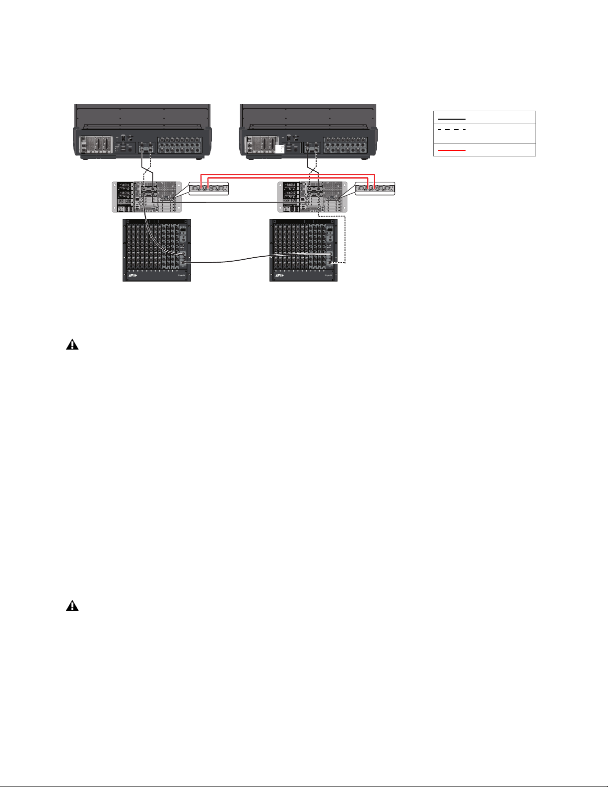
Synchronization 360
Synchronizing Two VENUE Systems Exchanging MADI in I/O Sharing Configurations
If MADI is being exchanged between two VENUE S6L Systems in an I/O Sharing configuration, there must be no word clock con-
nection between engines (Internal sync, as shown in the figure below).
If you are also connecting external digital devices, there should be a single external word clock connection from a distributed mas-
ter word clock source (recommended) or from a single external device to one E6L Word Clock input only.
Using Word Clock to Synchronize a VENUE S6L System and Another MADI Device
When using MADI to connect your VENUE S6L system to a single external MADI device such as a digital mixing console, the
VENUE system can receive or provide word clock.
To synchronize a VENUE S6L system to a single external MADI device using word clock:
Connect a coaxial cable from the word clock out of the external MADI device to the WORD CLOCK IN port on your E6L en-
gine.
The external MADI device must be set to send 96 kHz word clock rate to your VENUE S6L system. The VENUE system auto-de-
tects external word clock and displays EXT in the Mode box on-screen. For an example diagram, see
Syncing an S6L System to
an External Device using Word Clock.
To synchronize a single external MADI device to a VENUE S6L system using word clock:
Connect a coaxial cable from the WORD CLOCK OUT port on your E6L engine to the word clock in port on your external
MADI device. For an example diagram, see Syncing External Devices to an S6L System using Word Clock.
The external MADI device may need to be configured to receive the 96 kHz word clock rate provided by the VENUE S6L system.
Check the device’s documentation.
Connecting MADI audio between two VENUE S6L systems configured for I/O Sharing, with no external word clock
Never connect word clock from one engine to the other when sharing I/O, and always make sure that only one E6L engine's word
clock input is connected if using an external word clock when sharing I/O.
At the time of this writing, the WC Out port on the MADI-192 MADI Option Card is not supported and should not be used.
IN
OUT
NETWORK
MASTER 1
WORD CLOCK
UTIL
EXPANSION
2
3
6
7
8
1
2
3
4
5
OKOK
A
B
AVB-192
ACT SIG ACT SIG
ACT SIG ACT SIG
A
B
A
B
A
B
IN
OUT
NETWORK
MASTER 1
WORD CLOCK
UTIL
EXPANSION
2
3
6
7
8
1
2
3
4
5
OKOK
A
B
AVB-192
ACT SIG ACT SIG
ACT SIG ACT SIG
A
B
ABCD EFGHJKLM
1
2
3
4
5
6
7
8
SIG +48V
SIG +48V
SIG +48V
SIG +48V
SIG +48V
SIG +48V
SIG +48V
SIG +48V
INPUT
SRI-192
1
2
3
4
5
6
7
8
SIG +48V
SIG +48V
SIG +48V
SIG +48V
SIG +48V
SIG +48V
SIG +48V
SIG +48V
INPUT
SRI-192
1
2
3
4
5
6
7
8
SIG +48V
SIG +48V
SIG +48V
SIG +48V
SIG +48V
SIG +48V
SIG +48V
SIG +48V
INPUT
SRI-192
1
2
3
4
5
6
7
8
SIG +48V
SIG +48V
SIG +48V
SIG +48V
SIG +48V
SIG +48V
SIG +48V
SIG +48V
INPUT
SRI-192
1
2
3
4
5
6
7
8
SIG +48V
SIG +48V
SIG +48V
SIG +48V
SIG +48V
SIG +48V
SIG +48V
SIG +48V
INPUT
SRI-192
1
2
3
4
5
6
7
8
SIG +48V
SIG +48V
SIG +48V
SIG +48V
SIG +48V
SIG +48V
SIG +48V
SIG +48V
INPUT
SRI-192
SIG MUTE
MUTE
MUTE
MUTE
MUTE
MUTE
MUTE
MUTE
SIG
SIG
SIG
SIG
SIG
SIG
SIG
OUTPUT
SRO-192
1
2
3
4
5
6
7
8
1
2
3
4
5
6
7
8
SIG +48V
SIG +48V
SIG +48V
SIG +48V
SIG +48V
SIG +48V
SIG +48V
SIG +48V
INPUT
SRI-192
1
2
3
4
5
6
7
8
SIG +48V
SIG +48V
SIG +48V
SIG +48V
SIG +48V
SIG +48V
SIG +48V
SIG +48V
INPUT
SRI-192
SIG MUTE
MUTE
MUTE
MUTE
MUTE
MUTE
MUTE
MUTE
SIG
SIG
SIG
SIG
SIG
SIG
SIG
OUTPUT
SRO-192
1
2
3
4
5
6
7
8
SIG MUTE
MUTE
MUTE
MUTE
MUTE
MUTE
MUTE
MUTE
SIG
SIG
SIG
SIG
SIG
SIG
SIG
OUTPUT
SRO-192
1
2
3
4
5
6
7
8
SIG MUTE
MUTE
MUTE
MUTE
MUTE
MUTE
MUTE
MUTE
SIG
SIG
SIG
SIG
SIG
SIG
SIG
OUTPUT
SRO-192
1
2
3
4
5
6
7
8
AVB-192
ACT SIG ACT SIG
ACT SIG ACT SIG
A
B
AVB-192
ACT SIG ACT SIG
ACT SIG ACT SIG
A
B
MADI-192
SRC
IN OUT IN WC OUTOUT
MADI-192
SRC
IN OUT IN WC OUTOUT
MADI-192
SRC
IN OUT IN WC OUTOUT
MADI-192
SRC
IN OUT IN WC OUTOUT
Primary network
Redundant network
MADI (coaxial)
(required)
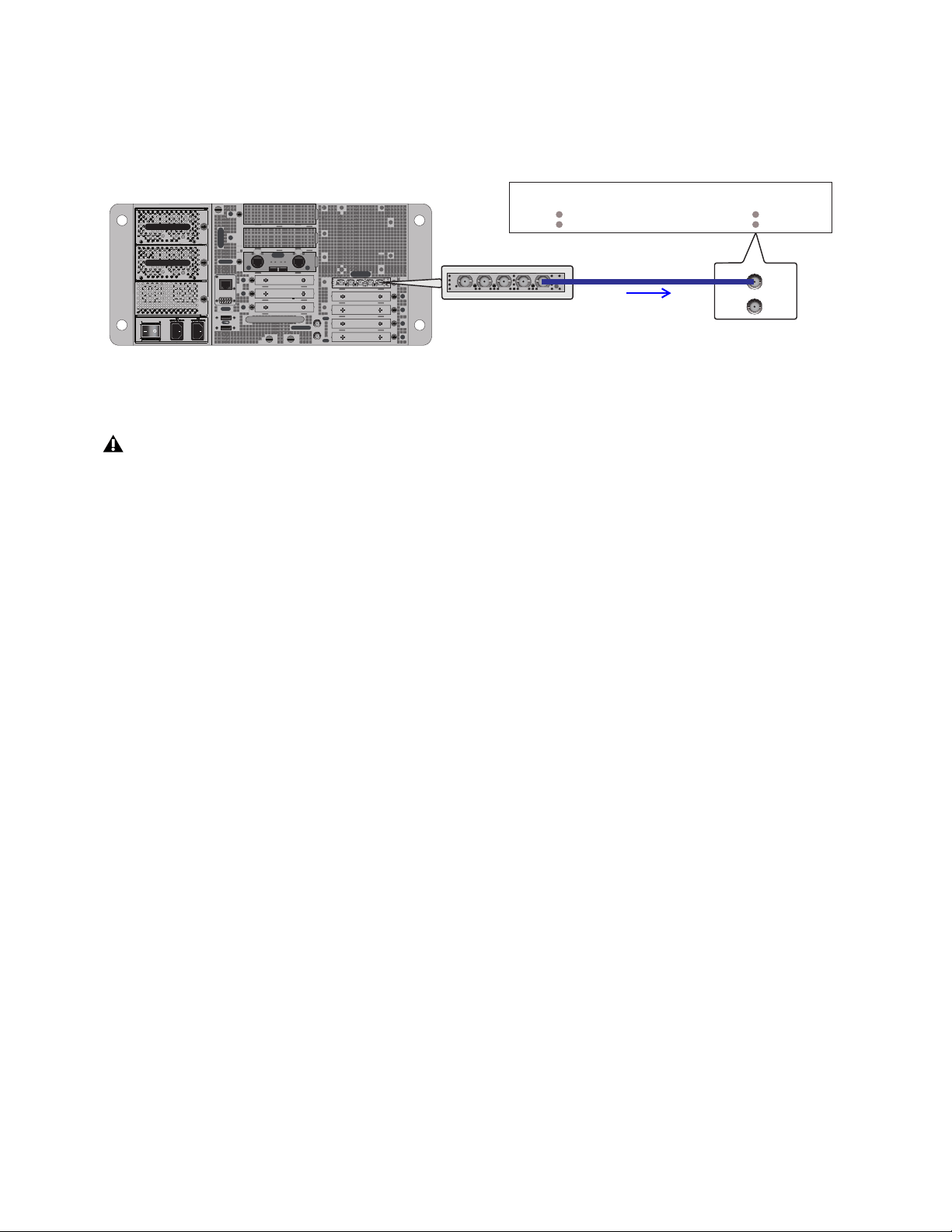
Synchronization 361
Using MADI Audio to Synchronize a Single External MADI Device to S6L
If your external device supports it, you can use the MADI signal from Stage 64, Stage 32, or MADI-192 MADI Option cards (if
any) to provide clock to your external MADI device. The device must be configured to sync to the incoming MADI signal. Refer
to the documentation for the device.
If your S6L systems are configured for I/O sharing, be sure to read and follow the guidelines in Important: Synchronization in
Shared I/O Configurations.
For additional information about MADI for recording, playback, and Virtual Soundcheck, see the VENUE S6L Live Recording
Guide.pdf.
External device connected and configured to sync to incoming MADI, supplied by MADI-192 MADI Option card MADI OUT
Only use high-quality BNC cables when attempting to use MADI sync. Lesser quality cables are susceptible to drop outs and loss
of sync.
IN
OUT
NETWORK
MASTER 1
WORD CLOCK
UTIL
EXPANSION
2
3
6
7
8
1
2
3
4
5
OKOK
A
B
AVB-192
ACT SIG ACT SIG
ACT SIG ACT SIG
A
B
MADI-192
SRC
IN OUT IN WC OUTOUT
MADI-192
SRC
IN OUT IN WC OUTOUT
MADI
IN
OUT
OUT
MADI-192 MADI Option Card
MADI OUT
WORD CLOCK
IN
External Device
Sync to: MADI IN
MADI
IN
OUT

Synchronization 362
Time Code
S6L provides a set of synchronization features that allow automation and remote control of snapshot and triggering of external de-
vices when snapshots are recalled via SMPTE MIDI Time Code (MTC) or Linear Time Code (LTC).
Automating Recall of Snapshots with Time Code
You can automate the recall of snapshots with MTC and LTC. The VENUE system can trigger snapshots with internally generated
MTC, or it can read incoming MTC or LTC from an external source.
Generating MIDI Time Code
You can set the VENUE system to generate MTC and automate the recall of snapshots based on MTC playback.
To generate MTC from the VENUE system:
1 On the external VENUE software screen, go to Options > Snapshots.
2 Enable Config mode.
3 Under Time Code, select MTC.
4 Select Generate. MTC generator (MTC GEN) controls appear in the banner display at the bottom of the screen.
5 Choose the MTC Frame Rate from the Frame Rate pop-up menu (24 fps, 25 fps, 30 fps drop, or 30 fps non-drop).
6 If you want MTC playback to start at a different time than the currently displayed time, enter a start time in the Start Time field,
and press Enter.
The custom start time is stored in the Show file.
7 Control MTC playback from the MTC generator controls by doing any of the following:
• Start MTC playback by selecting the Play button.
• Pause MTC playback by selecting the Pause button.
• Stop MTC playback and reset to the Start Time by selecting the Stop button.
For a diagram showing LTC and MTC ports, see
S6L Control Surface Connections.
MTC selected as the Time Code Format
MIDI Time Code set to Generate (left) and the MTC generator controls (right)
Performing a Clear Console resets the start time to the default of 01:00:00:00.

Synchronization 363
Configuring S6L to Slave (Chase) External Time Code
The VENUE system can slave to external MTC or LTC and automate the recall of snapshots based on the incoming time code. In-
coming time code can also be used as a Trigger in Events. VENUE automatically detects the frame rate of the incoming time code
when enabled. The following frame rates are supported: 24 fps, 25 fps, 30 fps drop, or 30 fps non-drop.
To configure S6L to slave to external time code:
1 On the external software screen, go to Options > Snapshots.
2 Do one of the following:
• To chase to incoming MTC, under Time Code Format, select MTC.
• To chase to incoming LTC, under Time Code Format, select LTC
3 Select Read. A time code display appears at the bottom of the screen.
The time code display indicates the following:
• When external time code is not present, the display shows a series of dashes.
• When external time code is present, the current time code value is shown in green.
• When time code is non-drop frame, HMSF separators are colons; when drop frame, HMSF separators are semicolons.
Snapshot Time Code Display
When the system is set to generate or read time code, the Snapshots list shows time code values and a green Recall Enable indicator
for each snapshot entry.
Assigning Time Code Values to Snapshots
With the S6L system set to generate or read time code, you can assign time code values to snapshots by entering values manually,
or by capturing time code playback values.
Manually Assigning Time Code Values to Snapshots
To manually assign an time code value to a snapshot:
1 In the Snapshots list, double tap the time code value you want to change.
2 Do one of the following:
• From the keyboard, type a new value.
– or –
• Press the Left and Right Arrow keys to move the cursor between number fields, and the Up and Down Arrow keys to increase
and decrease the selected value.
3 Press Enter or select another snapshot time code value to accept the entry.
Time Code display (drop frame LTC shown)
Snapshots list showing time code values and indicators

Synchronization 364
Capturing Time Code Values in Snapshots
To capture the current time code value in a new snapshot:
1 With the system in Read or Generate mode, start time code playback.
2 Do one of the following:
• During playback, select the New button.
– or –
• Pause playback at the time code value you want to capture, and select the New button.
A new snapshot appears with the time code value at the time of creation.
To capture the current time code value in an existing snapshot:
Tap-and-hold (right click) the snapshot in the Snapshots list and choose Set Time Code To from the menu.
The time code value is updated to the currently displayed value.
Sorting Snapshots by Time Code Value
You can sort snapshots in the Snapshots list by time code value, so that they appear in chronological order.
To sort snapshots by their assigned Time Code value:
Tap-and-hold (right click) any snapshot in the Snapshots list and choose Re-Sort All By Time Code from the menu.
Enabling Snapshots for Automated Recall
With time code values assigned to snapshots, you can then enable individual snapshots for recall with time code playback.
To enable snapshots for automated recall with time code:
Select the Time Code Recall Enable indicator on the right side of the Snapshots list. The indicator turns bright green to indicate
that the snapshot is enabled for recall.
Snapshot Chase to Time Code
With snapshots enabled for automated recall, the Chase function needs to be engaged to allow automated recall to occur. When
MTC is selected the button appears as Chase MTC. When LTC is selected, the button appears as Chase LTC.
To initiate automated recall of snapshots:
1 Make sure you have followed the instructions in
Configuring S6L to Slave (Chase) External Time Code.
2 Select the Chase MTC/LTC button so that it is highlighted.
3 Begin time code playback by starting the internal generator (if set to MTC Generate) or the external device (if set to Read).
When a recall-enabled snapshot’s time code value is reached, the snapshot is recalled.
The Chase MT/LTC button can be used to quickly take VENUE system offline from time code-triggered recall in performance in
the event of a change in timing, such as a missed cue or dropped verse. You can then advance manually to an appropriate snapshot,
and re-enable
Chase MTC.
When chasing to MTC, snapshots will always recall in chronological order, regardless of their order in the Snapshots list.
Make sure the Start Time (Options > Snapshots) is earlier than the beginning of incoming time code.
Snapshot modes can affect MTC recall. For more information, see
MTC/LTC and Other Online Event Triggers.
VENUE systems do not chase up to the current time code value. If you start playback in the middle of a snapshot sequence, any
prior snapshots will need to be recalled manually to update the system before beginning time code playback. For more infor-
mation, see
Recalling Snapshots.
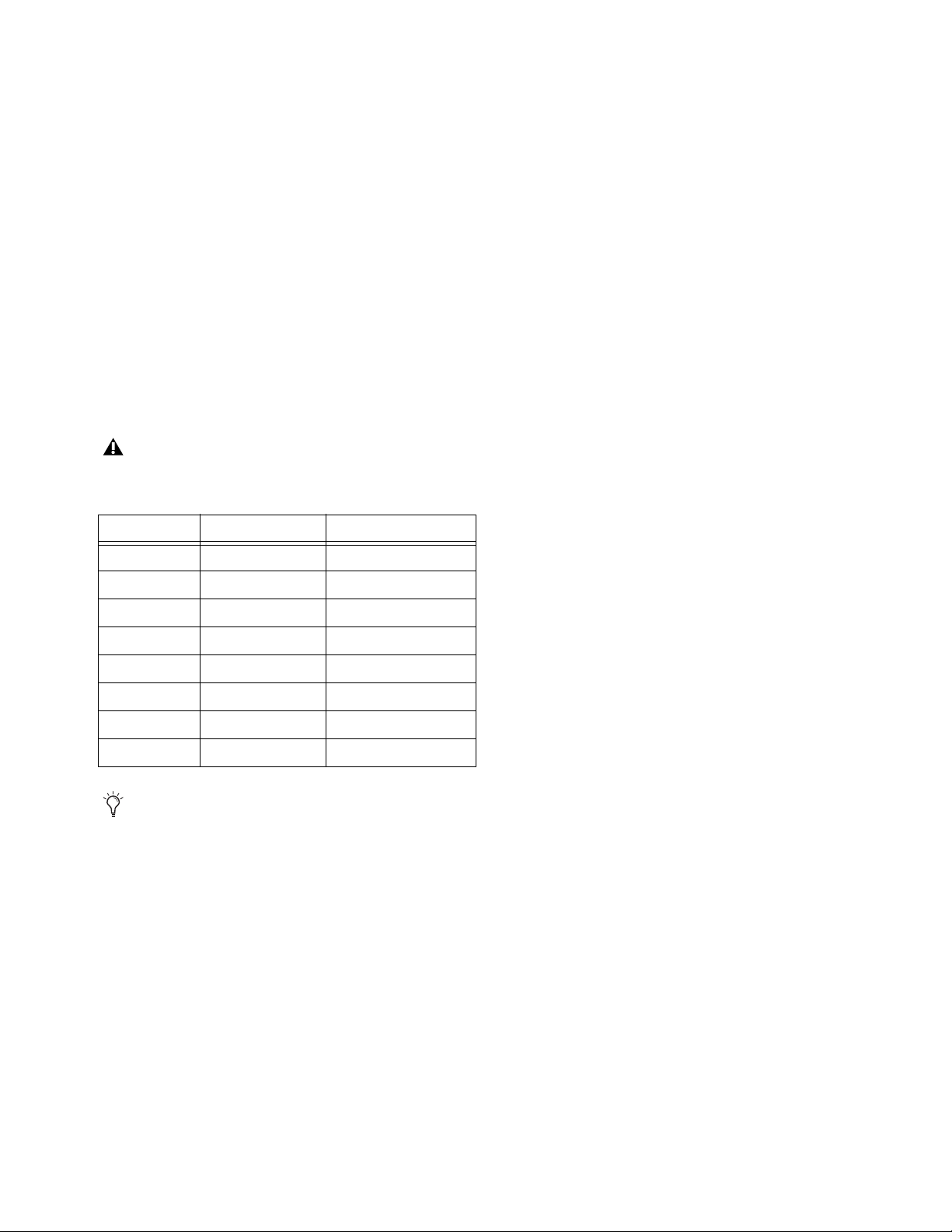
Synchronization 365
Remote Control of Snapshot Recall
The VENUE system can be set to recall snapshots in response to MIDI control messages sent from an external device such as an
AV controller system. You can set the system to respond to control messages sent on any one of 16 available MIDI channels.
The following information describes legacy snapshot recall via MIDI Bank Select and Program Change messages, which can recall
Parent or unaffiliated snapshots but not Child or Momentary snapshots. You can instead use MIDI Input to trigger recall of any
snapshot using
Events.
Using MIDI Bank Select and Program Change to Recall Snapshots
Snapshots are recalled when their snapshot number (1–999) is received in the form of MIDI Bank Select and Program Change mes-
sages. (See Table 7 on page 365.)
To enable recall of snapshots from an external device:
1 On the external software screen, go to Options > Snapshots.
2 Under MIDI, select the Snapshots Respond to Channel option, and choose the MIDI channel from the corresponding pop-up
menu.
The system listens on the specified channel for Bank Select and Program Change messages.
The MIDI Snapshot Output Safe option (Options > Snapshots page) does not affect this option. You can only turn off this feature
by de-selecting the “Snapshots Respond to Channel” option.
Table 7. MIDI Bank and Program Numbers for Snapshots
Bank Program Snapshot Number
0 0–127 001–128
1 0–127 129–256
2 0–127 257–384
3 0–127 385–512
4 0–127 513–640
5 0–127 641–768
6 0–127 769–896
7 0–103 897–999
VENUE software stores Bank Select messages, so it is not necessary to send a Bank Select message prior to every Program
Change message. You only need to send a Bank Select message when you want to recall a snapshot in a different bank from the
previous snapshot.

Synchronization 366
Triggering of External Devices on Snapshot Recall
The VENUE system can be set to send MIDI Bank and Program Change messages whenever a snapshot is recalled, to trigger ex-
ternal devices whose cues are related to snapshots. You can set the system to send on any one of 16 available MIDI channels.
While it is possible to add Bank Select and Program Change messages to individual snapshots, this option lets you toggle messages
on and off for all snapshots in one step. Using this option also ensures that the Bank Select and Program Change messages corre-
spond to the snapshot number, even after snapshots are rearranged in the Snapshots list.
The Bank Select and Program Changes messages reflect the number (1–999) of the recalled snapshot. (See
Table 7 on page 365.)
To enable triggering of external devices when snapshots are recalled:
1 On the external software screen, go to Options > Snapshots.
2 Under MIDI, select the Snapshots Send on Channel option, and choose the MIDI channel from the corresponding pop-up
menu.
The VENUE system sends a Bank Select and Program Change message on the specified channel whenever a snapshot is recalled.
Sending MIDI Messages on Snapshot Recall
You can add up to 20 specific MIDI messages to each snapshot. These messages are sent whenever the snapshot is recalled. Send-
ing of the messages is enabled with the MIDI scope control in the Snapshots window. For more information, see
Adding MIDI and
Plug-In Data to Snapshots.
MIDI output is automatically suspended while in Preview mode. For more information, see Preview Mode.
You can also use
Events to trigger MIDI output.
VENUE systems always send a Bank Select message before every Program Change message, even if the bank number has not
changed from the previous snapshot.
The MIDI Snapshot Global Safe option (in the Recall Safe tab of the Snapshots page) does not affect this option. You can only
turn off this feature by de-selecting the “Snapshots Send on Channel” option.

Connecting and Using the MADI-192 MADI Option Card 367
Connecting and Using the MADI-192 MADI Option Card
If you have installed one or more MADI-192 MADI Option Cards in your E6L engine you can make audio connections between
your VENUE system and your MADI device.
You must establish proper synchronization between your VENUE system and any connected MADI devices. You may or may not
need to make additional connections. See
Synchronizing MADI Devices.
In VENUE Standalone software version 5.3 or higher, you can add MADI cards to the configuration in the EXPANSION CARDS
section of the Options > Devices page. You can then view MADI Device information and settings, but you cannot change settings.
Making Audio Connections
This section shows how to make the audio connections between your VENUE S6L system and your MADI device.
(For installation instructions, see the MADI-192 Card Installation guide, included with the card and available for download from your
Avid account.)
Sending Audio
The MADI-192 MADI Option Card provides two coaxial outputs. Both coaxial outputs of the MADI card are active at all times.
To connect a MADI device to your VENUE system:
1 Power up your VENUE system.
2 Connect to your MADI device using the coaxial MADI Output connectors of the MADI card.
Receiving Audio
When your VENUE system is receiving audio from a MADI device, both coaxial inputs on the MADI-192 MADI Option Card are
available at all times.
To connect a MADI device to your VENUE system:
1 Power up your VENUE system.
2 Connect to your MADI device using the coaxial MADI Input connectors of the MADI card.
S6L systems cannot clock directly to incoming MADI audio. You must establish proper synchronization between your VENUE
system and any connected MADI devices. See
Synchronizing MADI Devices.

Connecting and Using the MADI-192 MADI Option Card 368
Using MADI
You can use the MADI-192 MADI Option card with your VENUE S6L system in the following ways:
Assignable Mode
In this mode, all signal paths of the MADI-192 card are available in the VENUE Patchbay, and can be patched freely. The MADI
card can also be used for Hardware Inserts via MADI.
Pro Tools Input Mode
In this mode, Pro Tools is the main source of audio signals for VENUE and can be used in either Input or Virtual Soundcheck
mode. Either mode can be configured to receive audio via AVB, or via MADI.
Input Mode
In this mode, audio from your AVB or MADI device is the main audio source for your VENUE system. Stage inputs
on your VENUE system are replaced with inputs from Pro Tools via AVB or MADI, or from an external MADI device such as an-
other VENUE system or another digital mixing console. Input channel gain and other PRE parameters such HPFs can be stored in
Snapshots.
Virtual Soundcheck Mode
In this mode, pre-recorded audio from Pro Tools via AVB or via an external MADI device is the main
source of audio for VENUE. Stage inputs on your VENUE system are replaced with inputs from your external MADI device.
Changes made in Virtual Soundcheck mode, including Snapshot creation and modification, carry over when switching back to
Stage mode. Input channel gain changes made while in Virtual Soundcheck mode can be applied to Stage input channels when
switching back to Stage mode. On systems with three or more MADI Option cards, only MADI-192 MADI Option Cards installed
in slots 1 and 2 are available for Virtual Soundcheck.
Redundant Outputs
You can install multiple MADI cards and operate them in a redundant output configuration. For redundant recording, you can also
enable both AVB and MADI as Virtual Soundcheck Destinations.
Assignable I/O
For any system input channels that have Stage inputs assigned as their sources, assignable recording outputs are available, up to the
maximum number of available Pro Tools I/O channels. Assignable outputs can be used to send the Main L/R mix, submixes from
sources such as Matrix and Groups, the Direct Outs of S6L system I/O channels, and audience mics to Pro Tools.
For any system input channels not assigned Stage inputs as their sources, assignable Pro Tools inputs are available, up to the max-
imum number of available Pro Tools I/O channels. Assignable inputs can be used to monitor your Pro Tools recording on your S6L
system, or to incorporate pre-recorded audio tracks into your live mix.
Hardware Inserts
Any MADI IO on MADI Option cards in slots 1 and 2 become unavailable as hardware inserts while MADI is selected as a Virtual
Soundcheck Source or Destination.
For more information about gain, snapshots, and other aspects of Virtual Soundcheck, see the S6L Live Recording Guide.pdf.

Connecting and Using the MADI-192 MADI Option Card 369
Enabling Virtual Soundcheck Recording
You can enable direct digital splits by configuring the System Outputs setting in Options > System. By default AVB is the desig-
nated system output destination. You can change this to MADI, or BOTH, to designate the MADI card as a Virtual Soundcheck des-
tination. The Pro Tools tab of the VENUE Patchbay feeds the cards. Up to two MADI cards can be used for Virtual Soundcheck.
The pickoff point for each Stage input split is post-analog input gain, but pre-digital trim and channel processing, including the
channel HPF. Thus, the gain for any input channel sent to Pro Tools is dependent on the S6L system input gain setting for that Stage
input channel.
Recordings of direct digital splits form the basis of the Virtual Soundcheck workflow, and are also useful for capturing unprocessed
audio files of your Stage inputs for later mixdown and editing.
To enable Stage inputs:
1 Make sure the Stage inputs you are using are patched to the desired S6L system input channels in the Patchbay.
2 Put your S6L system into Config mode.
3 On the external VENUE software screen, go to the Options > System tab.
4 In the System Inputs section, make sure Stage is selected. If Stage is not selected, do the following:
•Select Edit.
•Select Stage.
•Select Apply.
Signals from any Stage inputs assigned to S6L system input channels are sent to the connected Pro Tools computer as direct digital
splits. The corresponding channels under the Pro Tools tab in the Patchbay are highlighted in purple to indicate they are in use as
digital split outputs and as Virtual Soundcheck inputs.
To configure Virtual Soundcheck Outputs:
1 Put your S6L system into Config mode.
2 On the external VENUE software screen, go to the Options > System tab.
3 Select Edit.
4 In the System Outputs section, choose one of the following from the Virtual Soundcheck Destination selector:
AVB
Splits are sent to Pro Tools via AVB.
MADI
Splits are sent to Pro Tools via the outputs on the MADI card.
Both
Splits are sent through both AVB and MADI.
5 Select Apply to apply your settings.
For complete instructions on setting up and using Virtual Soundcheck, see the S6L Live Recording Guide.pdf.
If you want to use VENUE Link for enhanced Virtual Soundcheck, it requires a dedicated Ethernet connection from port C on the
S6L control surface to the Pro Tools computer. For more information, see the S6L Live Recording Guide.pdf
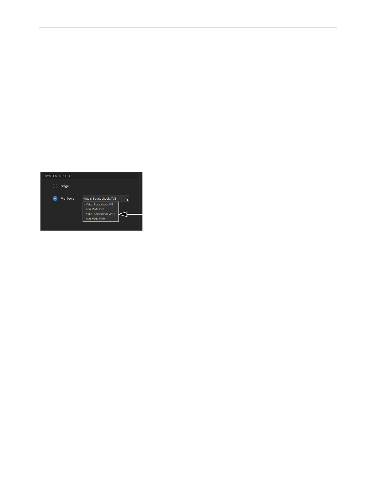
Connecting and Using the MADI-192 MADI Option Card 370
Performing a Virtual Soundcheck using MADI-192
In Virtual Soundcheck mode, audio from your external MADI devices can replace the corresponding Stage inputs one-for-one, and
appear in place of those Stage Inputs in the VENUE software Patchbay. All changes (such as channel assignments, and input and
output processing) are carried over when you switch to Virtual Soundcheck mode, and the digital portion of the gain for each chan-
nel is preserved and applied to the incoming MADI signal. This results in the same apparent levels for both the MADI inputs and
the Stage inputs.
To perform a Virtual Soundcheck using MADI:
1 Do one of the following to put your system into Config Mode:
• Press the Config switch on the console.
• Double-click the Mode box in the bottom-right corner of the screen.
2 Go to the Options > System tab to access the System Configuration page.
3 Click Edit.
4 In the System Inputs section of the System Configuration page, click to enable Pro Tools.
5 Choose Virtual Soundcheck MADI from the Pro Tools selector.
6 Click Apply.
All S6L system input channels with Stage inputs assigned to them are replaced with their corresponding Virtual Soundcheck in-
puts from Pro Tools. Pro Tools icons appear in the Patchbay > Inputs tab patching grid for all assigned Stage inputs, indicating
that input sources for the affected input channels are now Virtual Soundcheck inputs from Pro Tools. Any MADI IO designated
as hardware inserts become unavailable as inserts (their patch assignments are retained).
If you change input routing when MADI inputs are active, those changes remain when you switch back to Stage input mode.
Virtual Soundcheck MADI option in the Pro Tools sector (Options > System)
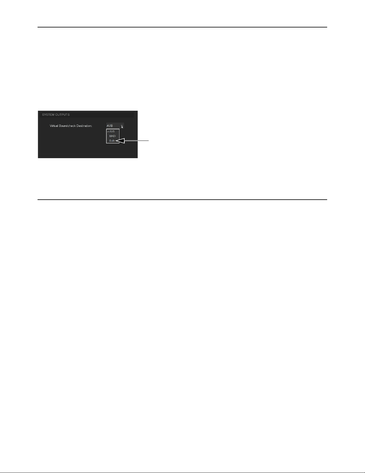
Connecting and Using the MADI-192 MADI Option Card 371
Enabling Redundant Outputs
For redundant recording, you can enable both AVB and MADI as Virtual Soundcheck Destinations.
To enable redundant outputs:
1 Put your S6L system into Config mode.
2 On the external VENUE software screen, go to the Options > System tab.
3 Select Edit.
4 In the System Outputs section, choose Both from the Virtual Soundcheck Destination selector:
5 Select Apply to apply your settings.
Using MADI for Hardware Inserts
MADI IO can be used as hardware inserts, just like other supported system IO. Hardware inserts can be used for external processing
on individual input channels, Mains, Groups, Auxes, and Matrixes. To use external hardware as inserts, you must do the following:
• Connect external hardware
• Assign hardware inserts to channels
• Activate the insert
• Set the hardware insert location
For instructions, see
Hardware Inserts, and be sure to note the following about MADI availability with Virtual Soundcheck mode:
• Whenever a MADI card is enabled as a Virtual Soundcheck destination, its IO becomes unavailable for use as hardware in-
serts. Assignments are retained (but disabled) when Virtual Soundcheck mode is enabled, and are restored when exiting Vir-
tual Soundcheck mode.
Enabling redundant outputs (Both) for the Virtual Soundcheck Destination (Options > System)

Hardware Inserts 372
Hardware Inserts
This chapter explains how you can connect external analog and digital hardware to the analog and digital I/O on the S6L control
surface, Stage I/O units, Local 16, or E6L engine (if any MADI-192 MADI Option cards are installed) for use as hardware inserts.
Hardware inserts can be used for external processing on individual input channels, Mains, Groups, Auxes, and Matrixes. To use ex-
ternal hardware as inserts, you must do the following:
• Connect external hardware
• Assign hardware inserts to channels
• Activate the insert
• Set the hardware insert location
Connecting External Hardware
External hardware is made available to the system by connecting its inputs and outputs to input and output connectors on the S6L
control surface (all except S6L-16C), Stage/Local I/O unit, or E6L engine (if any MADI-192 MADI Option cards are installed).
Hardware inserts can then be inserted on channels similarly to inserting plug-ins.
To connect outboard gear for use as a hardware insert:
1 Connect the inputs of the external device to analog and/or digital output connectors 1–8 on the S6L control surface or Local 16.
2 Connect the outputs of the external device to the corresponding input connectors on the S6L control surface or Local 16.
For example, signal taken from S6L control surface AES Digital outputs 1/2 must be returned to S6L control surface AES Digital
input 1/2.
Using MADI-192 MADI Option Card IO for Hardware Inserts
If your system includes one or more MADI-192 MADI Option cards, you can use its inputs and outputs for hardware inserts from/to
the E6L engine. For details on configuring and using MADI Option card inserts, see the Using MADI for Hardware Inserts.
The S6L-16C control surface does not support IO connections for hardware inserts. Use Local 16 or Stage I/O instead.
Digital inputs on the S6L control surface and on the DSI-192 card offer sample rate conversion. For more information, see Syn-
chronizing AES/ADAT Digital Audio Inputs (SRC).

Hardware Inserts 373
Assigning Hardware Inserts to Channels
You can assign hardware inserts directly from the Inputs or Outputs page, or from the Patchbay.
To assign a hardware insert to a channel or bus:
1 On the external VENUE software screen, go to the Inputs or the Outputs page and attention the channel on which you want to
insert the external device.
2 In the Inserts section, do one of the following:
• Select the Hardware Insert pop-up menu and choose an insert destination directly from the menu. The name of the hardware
insert destination appears in the on-screen Hardware Insert button.
– or –
• Select the Hardware Insert button to “jump” to the Inserts tab of the Patchbay, and assign the insert from the Patchbay.
To assign a hardware insert from the Patchbay:
1 On the external software screen, go to the Patchbay page and select the Inserts tab. The Console hardware tab is shown.
2 Click a tab along the left side of the grid to show the desired channel types in the grid. If you jumped to the Patchbay from the
Inputs or Outputs page, the appropriate Channel Type tabs are automatically selected.
3 Touch in the channel grid to assign the hardware insert input/output (listed across the top) to the channel where you want to as-
sign the insert (listed on the left).
The Insert location is also displayed in the Hardware Insert pop-up in the Inserts section of the Inputs or Outputs page for the at-
tentioned channel.
Reassigning Hardware Inserts
If a hardware input is currently assigned to an input channel and then reassigned as a hardware insert, the gain on that input is au-
tomatically set to 0 dB. When reassigning a hardware input from an insert to an input channel, the gain setting for that channel is
automatically set to +10 dB.
Input and output levels to and from devices assigned as hardware inserts are automatically set to 0 dB, and cannot be changed
in VENUE. Set trims on the device itself.
Hardware Insert pop-up (left), Hardware Insert button to jump to the Inserts tab (right)
Assigning a hardware insert on the Inserts tab of the Patchbay I

Hardware Inserts 374
Activating and Bypassing Hardware Inserts
You can toggle hardware inserts in/out on-screen, and from the control surface using Events.
To activate or bypass a hardware insert on-screen.
1 Go to the Inputs or Outputs page and select the channel where you want to activate or bypass the insert.
2 Click the In/Out button for the HW insert. The button lights when the insert is activated (in circuit).
You can also define an Event to toggle a hardware insert in/out via a Function or other hardware switch, a fader or other continuous
control, MIDI input, or a system value. For instructions on how to create and define Events, see Events.
Setting the Hardware Insert Location
You can choose the location of the hardware insert in the signal path relative to the four plug-in inserts on a per-channel basis.
To set the hardware insert location:
1 Go to the Inputs or Outputs page and select the channel where you want to set the hardware insert location.
2 In the Inserts section, select the hardware insert indicator in one of the five available locations so that it lights red.
Before activating a hardware insert, be sure that you have connected the external unit to your S6L system. If you activate the
hardware insert and audio on that channel is not present, double-check your cabling to make sure it is connected correctly.
Activating a hardware insert
Any HW inserts on MADI-192 cards are unavailable when VSC MADI is enabled. For details on configuring MADI Option
card inserts, see the
Using MADI for Hardware Inserts.
Hardware insert indicator showing the hardware insert before the first plug-in (left), and after the first plug-in (right)
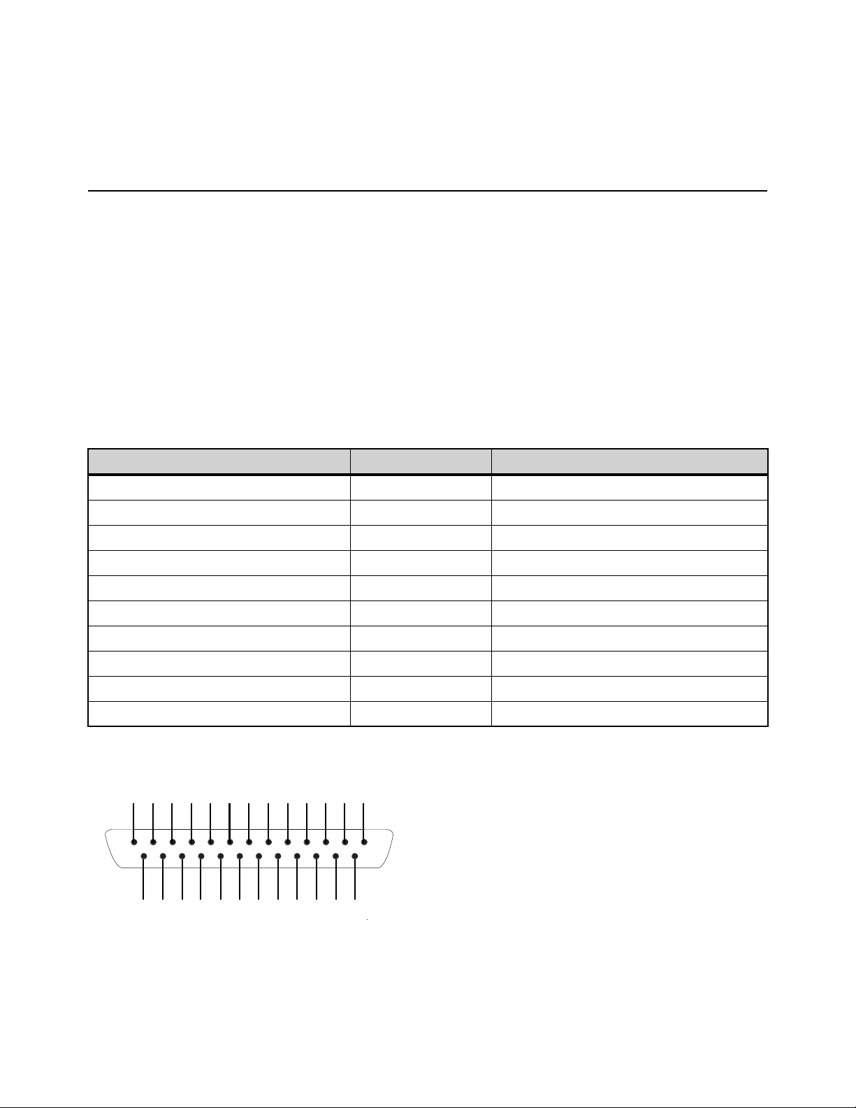
GPI Port Reference 375
GPI Port Reference
GPI Input Specifications
A 25-pin, male D-Sub connector provides a total of 8 General Purpose Interface (GPI) Inputs. GPI inputs have the following char-
acteristics:
• Inputs are logic inputs with pull-ups. They may be driven by logic outputs or contact closure to ground.
• Input signal range is 0 to 5.5V. The inputs are ESD protected.
• Input signaling uses standard 5C CMOS logic levels: 1.5 V or less for a logic low. 3.5 V or greater for a logic high.
• Inputs are compatible with 5V TTL (e.g. 74LS series) and 5V CMOS (e.g. 74HC series)
• Inputs provide an internal 5K ohm pull-up to +5V.
• All Inputs are referenced to the same internal ground, which is connected to AC safety ground.
GPI Input Connector Pin Assignments
Pinout for GPI Input Connector
GPI Input Connector Pin Assignments (DB25 male)
Pin Number Function Comments
1 Input 1 Logic level (TTL, CMOS) input with pullup
2 Input 2 Logic level (TTL, CMOS) input with pullup
3 Input 3 Logic level (TTL, CMOS) input with pullup
4 Input 4 Logic level (TTL, CMOS) input with pullup
5 Input 5 Logic level (TTL, CMOS) input with pullup
6 Input 6 Logic level (TTL, CMOS) input with pullup
7 Input 7 Logic level (TTL, CMOS) input with pullup
8 Input 8 Logic level (TTL, CMOS) input with pullup
14, 15, 16, 17, 18, 19, 20, 21 Ground All ground pins are connected together internally
9, 10, 11, 12, 13, 22, 23, 24, 25 Reserved Do not use
Pinout for S6L DB25M GPI Input port (looking at back of console)
1 2 3 4 5 6 7 8 910111213
14 15 16 17 18 19 20 21 22 23 24 25
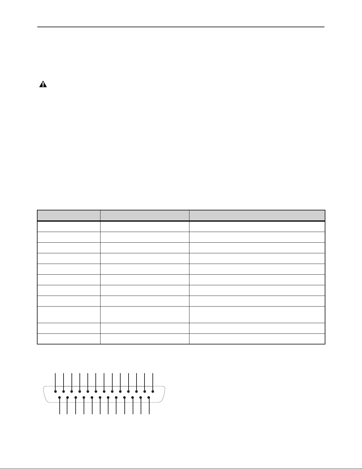
GPI Port Reference 376
GPI Output Specifications
A 25-pin, female D-Sub connector provides a total of 8 General Purpose Interface (GPI) Outputs.
• Outputs are isolated, floating relay contacts (contact closure).
• Switched voltage is 200V max; 0.5A max.
• Switched voltage with respect to safety/chassis ground is 300V max.
GPI Output Power Specification
The GPI Output connector also provides +12VDC at up to 200 mA for powering external devices, such as relays or LEDs. The
ground return that is provided is the S6L internal system ground, which is connected to AC safety ground.
GPI Output Ground Connections
The GPI Outputs provided are isolated contact-closure style. Each GPI output is presented on a pair of pins. These two pins repre-
sent the two sides of a switch that can be opened and closed. If it is desired to drive a signal to ground, then one of the pins must
be wired to ground, and the other to the signal to be controlled.
GPI Output Connector Pin Assignments
:
DB25F Pinout
GPI Outputs can switch 500 mA maximum. This applies even to short term current surges. This limit can be exceeded when driv-
ing a capacitive or incandescent lamp load. An incandescent lamp may draw as much as ten times its steady state current when
first turned on. Therefore such lamps are typically not appropriate loads for the GPI Outputs, and should instead be controlled
by a secondary relay.
GPI Output Connector Pin Assignments (DB25 female)
Pin Number Function Comments
1, 14 Output 1 Floating contact closure output
2, 15 Output 2 Floating contact closure output
3, 16 Output 3 Floating contact closure output
4, 17 Output 4 Floating contact closure output
5, 18 Output 5 Floating contact closure output
6, 19 Output 6 Floating contact closure output
7, 20 Output 7 Floating contact closure output
8, 21 Output 8 Floating contact closure output
12, 13, 24, 25 +12V auxiliary power Maximum total load 200 mA
All +12V pins are connected together internally
9, 10, 22, 23 Ground for auxiliary power All ground pins are connected together internally
11 Reserved Do not use
Pinout for S6L DB25F GPI Output port (looking at back of console)
12345678910111213
141516171819202122232425
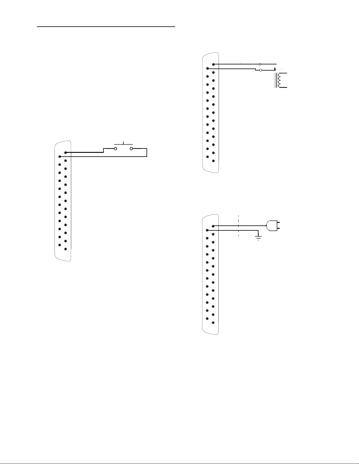
GPI Port Reference 377
GPI Wiring Diagrams
The following diagrams provide examples of GPI pinout and
wiring for the common uses. All diagrams are shown from the
rear (solder side) of the DB25 connector.
GPI Input Examples
The following diagrams provide simplified wiring examples
for a customer-provided DB25 female connector, to attach to
the male GPI In connector on the S6L control surface.
Wiring a Switch to Drive GPI
No ground reference is needed between systems.
Wiring a Relay to Drive GPI
No ground reference is needed between systems.
Wiring a Logic Signal to Drive GPI
Ground reference is required between systems
DB25F connector
1
14
DB25F connector
DB25F connector
1
14
1
14

GPI Port Reference 378
GPI Output Examples
The following diagrams depict wiring examples for a cus-
tomer-provided DB25 male connector, to connect to the female
GPI Output connector on the S6L control surface.
GPI Output Driving a Relay to Illuminate a Light
No ground reference is needed between systems.
GPI Output Driving and Powering an LED
Connect one side of the relay to Ground.
GPI Output Driving an Externally Powered LED
GPI Output Driving a Logic Input
Ground reference is required between systems.
DB25M connector
DB25M connector
External
Power
Supply
1
24
14
9
1
24
14
9
DB25M connector
DB25M connector
1
14
External
Power
Supply
+
–
V +
1
14
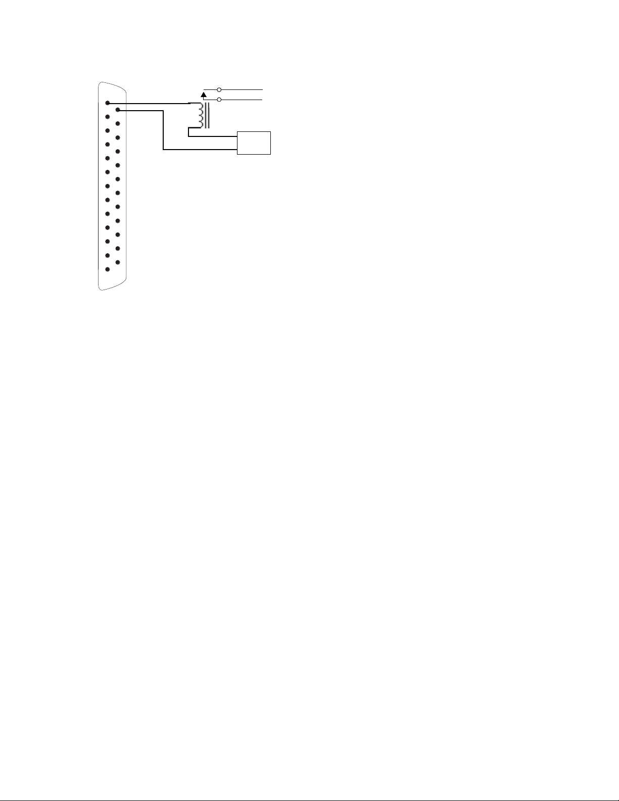
GPI Port Reference 379
GPI Output Driving a Relay Using an External
Power Supply
DB25M connector
External
Power
Supply
1
14
DB25M
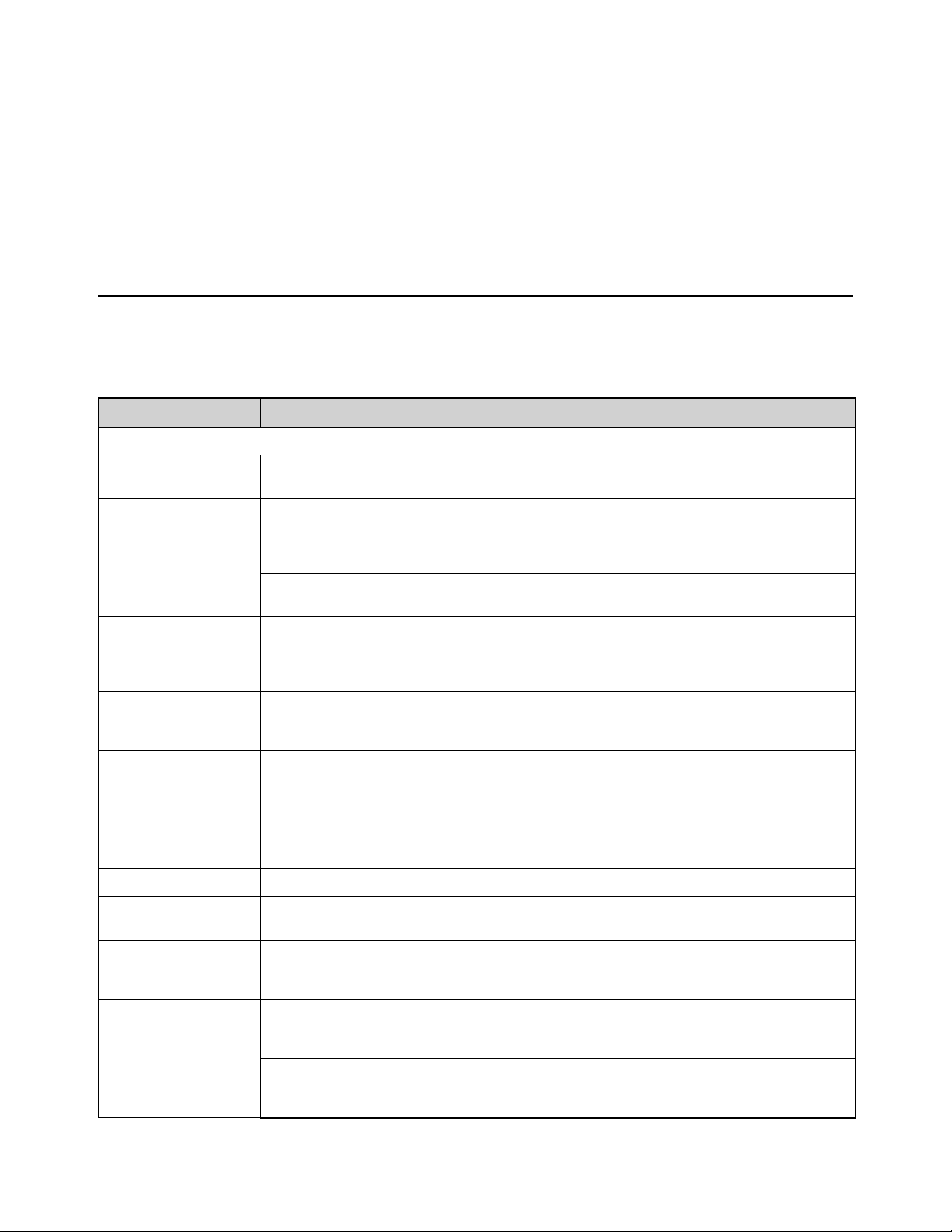
Troubleshooting 380
Troubleshooting
This chapter provides troubleshooting and problem solving information. It includes a table of problems and solutions that provides
answers to common questions, explains on-screen text messages, and refers you to specific sections later in this chapter or else-
where in this guide for details and instructions.
Problem Solving
The following table provides descriptions of situations that may arise while operating a VENUE system and includes common
questions, symptoms and error messages, along with possible solutions.
Table 8. Troubleshooting Errors and Messages
Symptom or Message Possible Cause Solution
Faders, Switches, Modules, Channels, and Devices
Fader stuck Fader path was blocked during startup cali-
bration.
Reset the S6L control surface. See
Resetting Hardware
Components
.
Control surface controls
have stopped working
S6L control surface needs to be reset. Reset the console. See Resetting Hardware Compo-
nents
. If possible, wait for a silent portion of a performance
to avoid unexpected gain changes upon reset. For details.
If software is frozen, power cycle the system.
Bad or missing connection to the E6L
engine.
Check to make sure the cable connecting the console to the
E6L engine is properly connected and not damaged.
Fader Module, Channel
Knob Module, Master Live
Module has stopped work-
ing/lost connection
Network error See
Restarting Your System.
Channel Touch Module
(CTM) offline (Please Con-
figure Console message)
Network error See
Resetting Channel Touch Modules (CTMs).
Stage I/O is not passing
audio
Stage unit needs to be reset. See Resetting Hardware Components.
Or, power-cycle the Stage 64
Bad or missing connection to the E6L
engine, to another Stage unit, or to power.
Check to make sure the audio network cable connecting the
Stage unit to the E6L engine (or, if daisy-chained, to the
nearest Stage unit) is properly connected and not damaged.
Check power to the Stage unit.
Cannot assign Stage 64 Config mode is not enabled. Enable Config mode. See
Enabling Config Mode.
S6L control surface /O is
not passing audio
S6L control surface I/O needs to be reset. See Resetting Hardware Components.
Or, power-cycle the control surface.
Touch on external screen
is reversed with MTS, or
not operating at all
Touchscreens are not configured properly
See
Configuring S6L Master Touch Screen (MTS)
and External Monitor.
Previously connected
device is unavailable and
is grayed out in the
Options > Devices page
The device is no longer present. Touch-and-hold (right-click) the device graphic in the
Options > Devices page and choose Forget <device> to dis-
miss warning dialogs.
Bad or missing connection to the E6L
engine.
Check to make sure the cable connecting the device to the
is properly connected and not damaged, and that the device
is powered on.
Troubleshooting 381
Startup and Restarts
Repeated failures An incompatible plug-in, a corrupted data
file or application software, or a hardware
error.
Check to make sure you are using the most current versions
of all your plug-ins (check with the manufacturers). If failures
occur only when you try to use a certain plug-in, disable that
plug-in and see if problems go away. Try re-installing
plug-ins that are causing problems.
Determine if a certain Show file causes the system to fail
consistently. If so, delete that file and see if problems persist.
For additional options, see
Restarting Your System.
Clear the console from the Options > System page and see
if problems persist.
If necessary, you can reinstall VENUE software by doing a
System Update. If you suspect problems with the system
hard drive, or the system software, you can do a complete
restore (see the
VENUE S6L Installation Guide.pdf).
Power down all equipment and check all cards and cable
connections and power supplies.
Plug-Ins
The plug-in racks need to
be reset
The plug-in racks have gone offline, and
LOST is indicated in the Status box
on-screen. The racks go offline after some
conditions in which a plug-in or the DSP
host failure causes significant problems.
Follow the instructions on-screen to reset the racks (see
Resetting the Plug-In Racks).
One or more plug-ins are
unavailable
A Show was loaded that references plug-ins
which are unavailable on the current sys-
tem.
Install the plug-ins, if available (see
Installing and Autho-
rizing Plug-Ins
).
Remove or replace the plug-ins in the Show, or load a differ-
ent Show file.
A plug-in is not fully compatible and is caus-
ing failures.
Check all plug-ins to make sure you are using the most
recent versions. Go to Options > Plug-Ins and Click the
plug-in to display the version number.
Try disabling plug-ins one-by-one to see if doing so elimi-
nates problems (see
Enabling and Disabling Installed
Plug-Ins
).
Plug-in authorization dia-
logs appear every time the
system starts or restarts
A plug-in is installed that needs to be autho-
rized for demo or full use.
Click Quit to dismiss the authorization dialog and continue
starting up (the plug-in will be unavailable).
Click Try to use the plug-in for a limited time in Demo mode.
Click Authorize if you are ready to authorize a plug-in using
an iLok. (See
Installing and Authorizing Plug-Ins.)
A plug-in demo has expired. Uninstall the plug-in listed in the authorization dialog (see
Uninstalling Plug-Ins).
Table 8. Troubleshooting Errors and Messages
Symptom or Message Possible Cause Solution

Troubleshooting 382
Warning Dialogs
One or More Devices Have
Failed
Bad or missing connection Check connections to other components.
A device needs to be reset. Reset the device. If unable to reset the device, power cycle
the device.
Plug-In Racks Need Reset The racks have gone offline because a
plug-in has failed, or some circumstances
have caused the DSP engines to require a
reset.
Follow the instructions on-screen to reset the racks (see
Resetting the Plug-In Racks).
Console Connection Error Bad or missing connection Check Network connections to the E6L engine.
A unit needs to be reset. Reset the device. If unable to reset the device, power cycle
the device.
Date & Time Check System clock needs to be reset. Reset the system clock. See Setting the System Clock.
Sample Rate Conversion
Alert
SRC OFF LEDs flashing
(Systems with DSI option
only)
A sample rate mismatch or lack of clock has
been detected at a digital input.
No immediate action required; automatic sample rate con-
version maintains digital throughput, allowing you to check
settings and connections between VENUE and external dig-
ital devices later. For more information on digital connec-
tions and synchronization, see
Synchronizing
AES/ADAT Digital Audio Inputs (SRC)
.
Hardware Monitor Alert The system has detected a hardware com-
ponent that is performing above or below its
hardware specification.
Click HW Monitor to access the Hardware Monitor Window
for the device. See
Resetting Hardware Components.
A Device Has Been Lost A Stage 64 has been disconnected or has
lost power.
Check power and/or connection to the device.
If the device is not present, right-Click the graphic of the cor-
responding Stage 64 and choose Forget IO Box Assign-
ment.
Control Surface Module
Lost
Network error See
Restarting Your System.
Redundant Connection
Lost
If a primary and redundant audio connection
has been made to the device, one of the
connections has been lost.
Check the audio network connection to the device. If a
redundant connection is not present, press OK to dismiss
the dialog.
Engine Internal Switch
Warning
Internal switch in the E6L engine has mal-
functioned
Power-cycle the E6L engine
One or more Engine fans
have stopped working
One or more fans inside the E6L engine
have failed
When possible, check the internal fan connections.
2 fan blocks in the Engine
have stopped working.
Your Engine will now shut-
down to prevent overheat-
ing.
All fans inside the E6L engine have failed. The E6L engine will not operate unless at least one fan block
is operational. When possible, check the internal fan con-
nections, and replace the fans is necessary.
External power supply of
HDX card(s) is discon-
nected.
Power cable is not connected to one or
more HDX cards in the E6L engine.
Shut down the E6L engine and check power connections to
HDX cards. See the HDX-192 DSP Installation Guide for
instructions on accessing the HDX cards and their power
cables.
Unsupported HDX DSP
configuration detected
HDX DSP card may be installed improperly Make sure you have installed your HDX DSP card in the cor-
rect slot in the E6L engine. See the HDX-192 DSP Installa-
tion Guide for instructions on properly installing the HDX
cards.
HDX DSP card requires
update
The version of the firmware on an HDX DSP
card in the E6L engine is incorrect
See
Updating HDX-192 DSP Card Firmware.
Table 8. Troubleshooting Errors and Messages
Symptom or Message Possible Cause Solution
Troubleshooting 383
MADI card requires update The version of the firmware on a MADI-192
MADI Option card is incorrect.
See
Updating MADI Card Firmware.
Clock Lost (or similar) The system(s) might be connected in an
unsupported clock configuration.
Make sure the WCOut port on the MADI-192 MADI Option
card is not connected. For more information, see
Connect-
ing and Using the MADI-192 MADI Option Card
.
VENUE On-Stage
Enter Password. Access to
this VENUE system is
locked.
Password protection has been enabled for
VENUE On-Stage.
See the
VENUE On-Stage.pdf for instructions on enabling,
configuring, disabling, and resetting password protection.
Table 8. Troubleshooting Errors and Messages
Symptom or Message Possible Cause Solution

Troubleshooting 384
Restarting Your System
If your VENUE system ever needs to be reset, restart the system
To restart the system:
1 On the external screen, go to the Options > System page.
2 Hold Default (Alt) and select Shut Down.
If restarting the system does not correct a problem, you may have to reset hardware components, identify and remove any incom-
patible plug-ins, or reinstall VENUE software using the System Restore software.
Additional Reset Options
Additional shortcuts are provided while restarting the system, which let you do the following:
• Back up the current show settings and clear the console. Use this option if you suspect an auto-saved setting has become cor-
rupted. This lets you save your most recent settings and clear the console without having to do a full system restore.
– or –
• Startup in Explorer, to be able to manually manage software components. Use this option to troubleshoot the system if problems
arise early in the startup process and persist through repeated restarts.
Backup and Clear Console
To backup and clear the console at restart:
1 Start or restart the system.
2 Watch the screen closely during the startup process. As soon as the cursor becomes visible (and before the VENUE software
logo screen appears) press and hold the C key on the computer keyboard. Continue to hold the C key (do not press it repeatedly).
3 A dialog appears that lets you choose to backup your auto-saved settings and clear the console, or to continue and load settings
normally.
Startup in Explorer
To start up the system in Explorer (bypassing VENUE software):
1 Start or restart the system, as necessary.
2 Watch the screen closely during the startup process. As soon as the cursor becomes visible (and before the VENUE software
logo screen appears) press and hold the E key on the computer keyboard. Continue to hold the E key (do not press it repeatedly)
until you see the Explorer desktop.
3 From Explorer, you can manually find and delete suspect data files, plug-ins, or perform other file management tasks.
If you press the C key too early in the startup process, the USB keyboard is reset instead of calling the Backup and Clear dialog.
If you do not see the backup and clear dialog, repeat the restart process and try again.
If you are unsure about how to troubleshoot a computer and its files, it is recommended that you contact VENUE customer ser-
vice.

Troubleshooting 385
Resetting Hardware Components
Some hardware can be reset from external screen Options > Devices screen, or by power-cycling the component. It is recom-
mended that you perform a reset if, for example, the Hardware Monitor Alert dialog appears for a specific device, if a connected
device stops communicating with the rest of the system, or if the device is not passing audio signal via its I/O.
To reset system hardware:
1 Put the system in Config mode.
2 On the external screen, go to Options > Devices.
3 Tap-and-hold (right-click) one of the following displayed hardware components:
• S6L control surface
• Stage 64 I/O racks (must be in the Connected Devices column)
4 Choose Reset.
Resetting Channel Touch Modules (CTMs)
If a CTM unexpectedly goes offline, indicated by Meters or Channel view not appearing on a CTM or a “Please Configure Con-
sole” message appearing, you can reset it from the MTS Control Surface Configuration page.
To reset an offline CTM:
1 On the MTS, touch the Gear icon.
2 Touch the Control Surface Configuration button.
The on-screen graphic show the status of the modules in your control surface
3 On the control surface graphic, tap the CTM that corresponds to the CTM that has gone offline, indicated by a warning icon. In
the Diagnostics window below the control surface graphic, information about the CTM’s status appear.
4 Touch the Unassign button to release the connection.
Gear icon
Control Surface Configuration button
Control Surface Configuration window showing and offline CTM
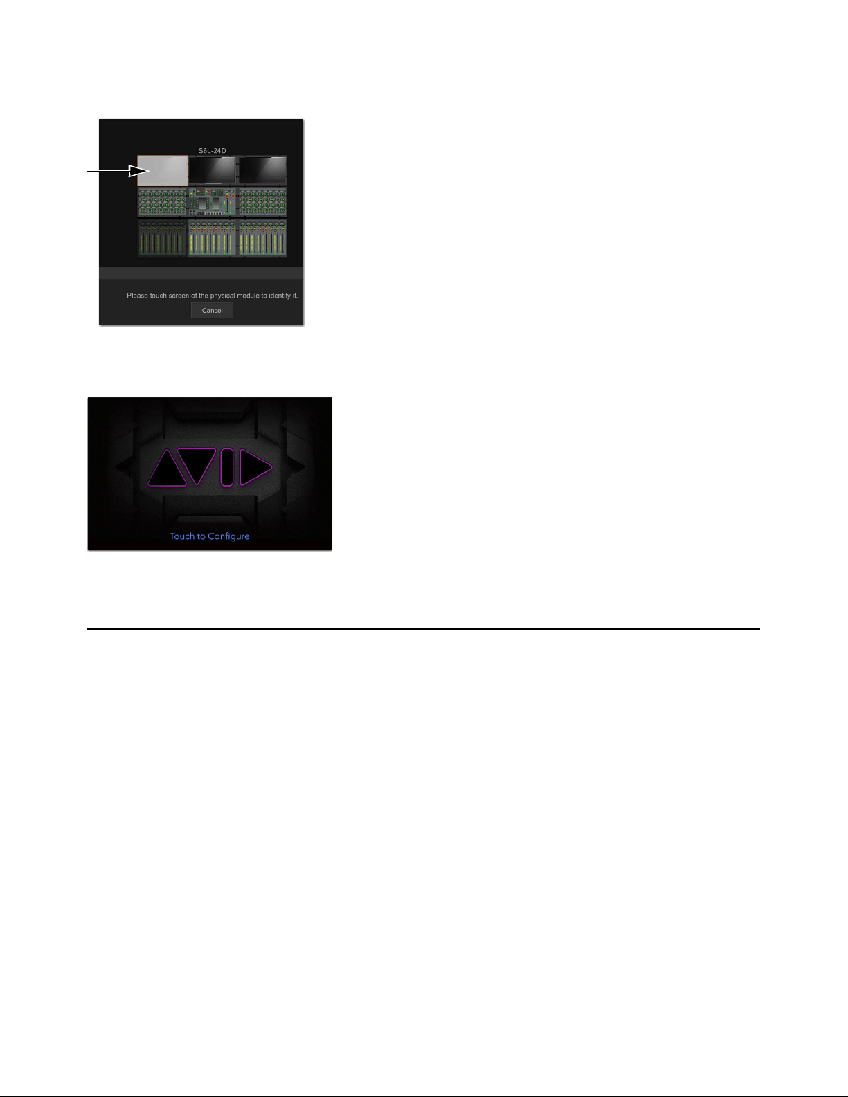
Troubleshooting 386
5 Touch Assign. The selected CTM flashes to indicate it is the module targeted for assignment.
If the wrong module is flashing, touch Cancel, touch the correct module so it is bordered in orange, and then touch Assign.
6 Touch the real CTM, which displays the message “Touch to Configure.”
When the CTM has been reconnected, the Meters view appears on-screen.
Offline or Unavailable Devices
The S6L system remembers the last hardware configuration used. If it doesn't find all units at the next startup, it displays those de-
vices as grayed out in the Options > Devices page. Devices remain offline (and the system displays error messages alerting you to
their absence) until either the devices are powered up and come online, or you tell the system to “forget” the offline devices.
Forget an offline device if that device is not currently a part of your configuration. If your device has failed or lost its connection,
check audio network connections or power-cycle the device.
To forget offline devices:
1 On the external screen, go to the Options > Devices page.
2 Touch-and-hold (right-click) the missing device and choose Forget.
Control Surface Configuration window showing a CTM ready to be assigned
CTM showing Touch to Configure

Troubleshooting 387
Hardware Monitoring Window
The performance of hardware components, including internal temperatures, can be viewed and monitored using the Hardware
Monitoring window.
Should a problem occur with any of the components in your system, the Hardware Monitoring window will provide information
that will be useful in troubleshooting while in contact with VENUE customer service.
Accessing Hardware Monitoring
To access the Hardware Monitoring window, do any of the following:
• Press Ctrl+Shift+M at any time to open the Hardware Monitoring window.
• On the Options > Devices page of the external screen, select a system component so it is highlighted in blue, and then in the
Information section choose Status.
• If the Hardware Monitoring Alert dialog appears on-screen, select OK in the dialog. The Hardware Monitoring Alert dialog
for the problem device appears automatically and identifies the reading that is out of specification.
The Hardware Monitoring Alert window is only displayed once per device (should a problem ever be detected with that device).
E6L Engine Emergency Shutdown
If the E6L engine has been disconnected from the S6L control surface and cannot be shut down via the Shut Down button on the
Options > System page of the external VENUE software screen, you can shut the engine down using the front-panel
Reset button.
To perform an emergency shut down of the E6L engine:
Press and hold the Reset button on the front panel of the E6L engine for at least 5 seconds.
When the System LED goes dark and the Status LED lights amber, you can then power off the engine’s PSUs.
Utility Mode
Each module on the S6L control surface (except CTMs) can be started up into a Utility mode that can be useful for troubleshooting
purposes. Only use Utility mode at the request of a qualified Avid technician to diagnose specific hardware problems.
To enter Utility mode on the MLM:
Press and hold the Multi-Select and Multi-Assign switches.
To enter Utility mode on a CFM:
Press and hold the Menu and Safe switches on the leftmost channel strip.
To enter Utility mode on a CKM:
Press and hold the encoder Sel switches on leftmost top-row encoders.

Troubleshooting 388
Resetting the Plug-In Racks
If the plug-in racks go offline they need to be reset to resume normal operation.
The following conditions apply when plug-ins go offline:
• When offline, plug-ins on input channels and continue to pass and process audio using their settings at the time the racks went
offline.
• Offline plug-ins on output channels and buses are muted.
• You will not be able to adjust plug-ins settings until the racks fully re-initialize.
• Once the racks begin to reinitialize, plug-ins are unavailable and do not process audio.
• During reinitialization, plug-ins are loaded into rack slots according to the last loaded Show file; plug-in racks are turned off
(all assigned plug-ins are made inactive).
• When all plug-ins have loaded and the racks initialized, the system displays a dialog alerting you that the racks are ready to
be brought back online (reactivated). This is provided as a final precaution against sudden changes to audio when plug-ins re-
sume processing.
Shortly after you confirm that you want the racks brought back online, plug-ins resume processing audio and all parameters become
available for editing.
To re-initialize (reset) the racks:
1 In the Plug-In Racks Reset dialog, Click Reset to begin the plug-in rack re-initialization.
2 In the Plug-In Racks are Ready dialog, Click Use Racks to confirm that you want the racks to be reset. Status is shown
on-screen. After the process is complete, the console and all plug-ins are operational again.
Using the System Restore Software
Use the System Restore software for troubleshooting or maintenance purposes. The S6L control surface and the E6L engine each
have their own unique System Restore image, which you must install on each device separately. S6L control surface and E6L en-
gine must both be running the same versions of VENUE software in order for them to connect. An active Internet connection is re-
quired to activate software components after installation.
See the most recent edition of the
VENUE | S6L Installation Guide.pdf (available in your Avid account) for complete instructions on
creating bootable USB drives for System Restore software, performing a System Restore or Software Update, and re-installing
plug-ins.
Do not reset the racks until there is a long enough break in the performance that the rack can be fully rebuilt with no signal pass-
ing through. This is especially important when using crossover plug-ins or gain-attenuating plug-ins.
Check your Avid account for the latest version of the System Restore software. Always make sure to use the latest version of the
System Restore software when restoring your software, and that you always keep a copy of the System Restore software on-hand
for troubleshooting.

Troubleshooting 389
Updating HDX-192 DSP Card Firmware
If you have installed an HDX-192 DSP card in your E6L engine, and on startup you encounter the message that the firmware needs
to be updated, use this procedure to update the firmware on the HDX DSP card.
To update the firmware on your HDX-192 DSP card:
1 Shut down your system, and power off all components.
2 Connect a VGA monitor, and USB keyboard and mouse to your E6L engine.
3 Power on your E6L engine, and repeatedly press F5 on the keyboard while the engine starts up.
4 Close the window that appears on screen to show the Desktop.
5 Double-click the Update HDX Firmware icon on the Desktop.
6 Follow the on-screen instructions to update the firmware on your HDX card.
When the firmware update completes, the E6L engine shuts down, indicated by the front-panel System LED going dark, and the
Status LED lit amber.
7 After the E6L engine shuts down, disconnect the VGA monitor, keyboard, and mouse, and power-cycle your E6L engine.
Updating MADI Card Firmware
If you have installed one or more MADI-192 MADI Option Cards in your E6L engine and on startup you encounter the message
that the firmware needs to be updated, use this procedure to update the firmware on the MADI card(s).
To update MADI-192 MADI Option Card firmware:
1 Shut down your system, and power off all components.
2 Connect a VGA monitor and USB keyboard and mouse to your E6L engine.
3 Power on your E6L engine, and repeatedly press F5 on the keyboard while the engine starts up.
4 Close the window that appears on screen to show the Desktop.
5 Double-click the Update MADI Firmware icon on the Desktop.
6 Follow the on-screen instructions to update the firmware on your MADI-192 MADI Option Cards.
When the firmware update completes, the E6L engine shuts down (indicated by the front-panel System LED going dark, and the
Status LED lighting amber).
7 After the E6L engine shuts down, disconnect power from the E6L and wait at least 30 seconds.
8 Make sure to disconnect the VGA monitor, mouse, and keyboard, then power your system back on.
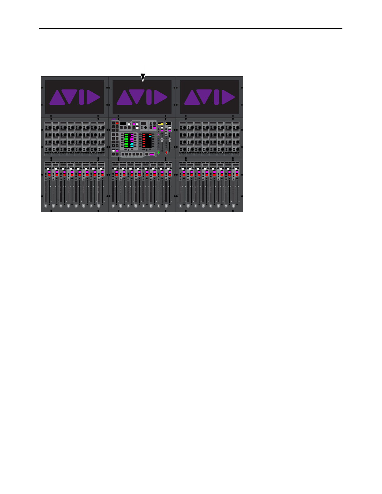
Troubleshooting 390
Configuring S6L Master Touch Screen (MTS) and External Monitor
If you replace your monitor and touch is not responding correctly on your MTS and/or your external monitor, use the Touch Screen
Assignment wizard to configure your touchscreens. This wizard only applies to the MTS and the external monitor.
To configure your screens:
1 Make sure your DVI monitor is connected to your S6L control surface and is powered-on.
2 On the MTS, touch the Gear icon.
3 Touch General, then touch Touch screen assignment.
4 Follow the on-screen prompts to configure your touchscreens. If prompted to press Enter, press the Enter key on your keyboard.
MTS on an S6L-24D
60
40
30
20
10
5
0
6
12
60
40
30
20
10
5
0
6
12
Select
Solo
Select
Solo
Select
Solo
Select
Solo
Select
Solo
Select
Solo
Select
Solo
Select
Solo
BAS
Menu Safe
Mute
Y
X
Y
X
Y
X
Y
X
Y
X
Y
X
Y
X
Y
X
BAS
Menu Safe
Mute
BAS
Menu Safe
Mute
BAS
Menu Safe
Mute
BAS
Menu Safe
Mute
BAS
Menu Safe
Mute
BAS
Menu Safe
Mute
BAS
Menu Safe
Mute
60
40
30
20
10
5
0
6
12
60
40
30
20
10
5
0
6
12
60
40
30
20
10
5
0
6
12
60
40
30
20
10
5
0
6
12
60
40
30
20
10
5
0
6
12
60
40
30
20
10
5
0
6
12
60
30
21
15
9
3
0
3
9
15
60
30
21
15
9
3
0
3
9
15
60
30
21
15
9
3
0
3
9
15
60
30
21
15
9
3
0
3
9
15
60
30
21
15
9
3
0
3
9
15
60
30
21
15
9
3
0
3
9
15
60
30
21
15
9
3
0
3
9
15
60
30
21
15
9
3
0
3
9
15
Nom
60
40
30
20
10
5
0
6
12
60
40
30
20
10
5
0
6
12
Select
Solo
Select
Solo
Select
Solo
Select
Solo
Select
Solo
Select
Solo
Select
Solo
Select
Solo
BAS
Menu Safe
Mute
Y
X
Y
X
Y
X
Y
X
Y
X
Y
X
Y
X
Y
X
BAS
Menu Safe
Mute
BAS
Menu Safe
Mute
BAS
Menu Safe
Mute
BAS
Menu Safe
Mute
BAS
Menu Safe
Mute
BAS
Menu Safe
Mute
BAS
Menu Safe
Mute
60
40
30
20
10
5
0
6
12
60
40
30
20
10
5
0
6
12
60
40
30
20
10
5
0
6
12
60
40
30
20
10
5
0
6
12
60
40
30
20
10
5
0
6
12
60
40
30
20
10
5
0
6
12
60
30
21
15
9
3
0
3
9
15
60
30
21
15
9
3
0
3
9
15
60
30
21
15
9
3
0
3
9
15
60
30
21
15
9
3
0
3
9
15
60
30
21
15
9
3
0
3
9
15
60
30
21
15
9
3
0
3
9
15
60
30
21
15
9
3
0
3
9
15
60
30
21
15
9
3
0
3
9
15
Nom
MIXMIXMIXPLUG-INSDYNAMICSEQINPUTCHANNEL
In
Sel
In
Sel
In
Sel
In
Sel
In
Sel
In
Sel
In
Sel
In
Sel
In
Sel
In
Sel
In
Sel
In
Sel
In
Sel
In
Sel
In
Sel
In
Sel
In
Sel
In
Sel
In
Sel
In
Sel
In
Sel
In
Sel
In
Sel
In
Sel
In
Sel
In
Sel
In
Sel
In
Sel
In
Sel
In
Sel
In
Sel
In
Sel
MIXMIXMIXPLUG-INSDYNAMICSEQINPUTCHANNEL
In
Sel
In
Sel
In
Sel
In
Sel
In
Sel
In
Sel
In
Sel
In
Sel
In
Sel
In
Sel
In
Sel
In
Sel
In
Sel
In
Sel
In
Sel
In
Sel
In
Sel
In
Sel
In
Sel
In
Sel
In
Sel
In
Sel
In
Sel
In
Sel
In
Sel
In
Sel
In
Sel
In
Sel
In
Sel
In
Sel
In
Sel
In
Sel
VENUE | S6L
Solo Solo
Home
Config
VCAs
Outputs
Layouts
Inputs
Flip
Recall
Trans
F1 F2 F3 F4 F5
NEXT
PREV
Store
Y
X
Y
X
AFL
Dim
In
Sel
SNAPSHOTS
Talk
Back
Multi
Select
Encoder
Assign
Select
Clear
Tap
Tempo
Multi
Assgn
Default Fine
OK Cancel
Over
Write
Mix to
Mon
Solo
Clear
60
40
30
20
10
5
0
6
12
60
40
30
20
10
5
0
6
12
8All
Preview
ASSIGNABLE ENCODER MONITORING
Push A/BHold SIP
SHIFT
ALT
CTRL
ESC
Mute Mute
A
B
Nom
30
21
15
9
3
0
3
9
15
30
21
15
9
3
0
3
9
15
Inputs/Outputs
Next
Global Controls
0.0 dB
L
Left
0.0 dB
Kick
Mute Group 1
Mute Group
Function KeysMute Group 2
Mute Group 3
Mute Group 4
Mute Group 5
Mute Group 6
M1
M2
M3
M4
M5
M6
0
01/011
reset all inputs
0.0 dB
CH 1
Kick
Ch 1-16
1-16
Aux 1-8
1-8
Aux 9-16
Aux 17-24
Aux 25-32
25-32
VCA 1-8
1-8
VCA 9-16
9-16
Ch 17-32
17-32 9-16
Ch 33-48
33-48 17-24
Ch 49-64
49-64
Ch 65-80
65-80
Ch 81-96
81-96
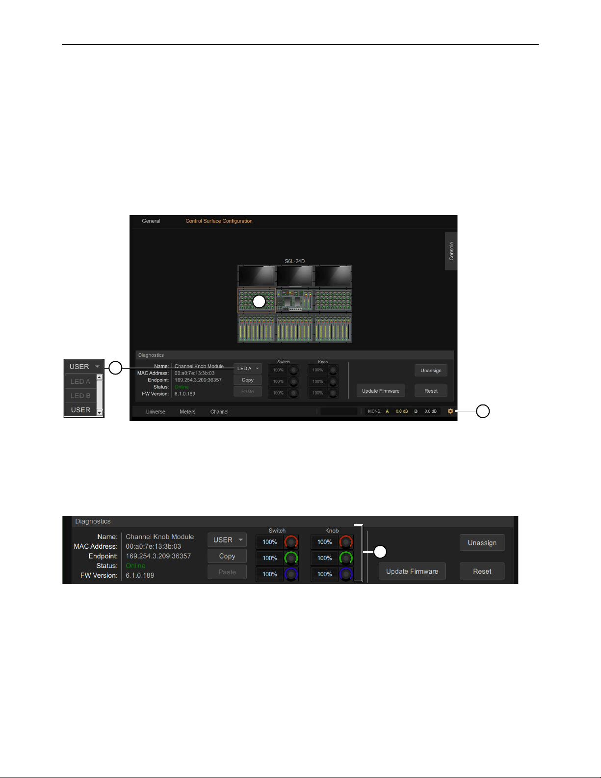
Troubleshooting 391
LED Brightness
Module LED Brightness Settings let you adjust the brightness of switch LEDs and knobs to match the brightness of modules of
varying ages or revisions. Using the Console Configuration page you can adjust brightness levels for knob and switch LEDs sep-
arately, and copy/paste all brightness settings from one module to another.
To adjust module brightness:
1 Access the Control Surface Configuration view by doing the following:
• S6L-32D/24D/24C: On the MTS touch the Gear icon, then touch the Control Surface Configuration tab.
• S6L-16C: On the external screen, go to Options > Control Surface Configuration.
2 On the control surface graphic, tap to select a module. The Diagnostics section appears below, showing module status and LED
brightness controls.
3 To choose a preset LED Mode for the selected module, choose LED A or LED B from the drop-down menu.
• LED A Maximum brightness, as found on newer or later revision S6L modules (100% for knobs and switches).
• LED B Less bright, to match newer replacement modules with older modules (Switch = 20/30/10%; Knob = 70/100/60%).
4 To customize settings, choose USER from the drop-down menu. The brightness controls for Switch and Knob become lit/active.
5 Adjust the red, green, and blue encoders for Switch and Knob.
6 To copy/paste the current brightness settings, tap Copy, tap to select a different module, then tap Paste. Settings can be cop-
ied/pasted from any type of module to any other (such as copying CKM settings to a CFM).
7 Repeat for other modules, as desired.
Control Surface Configuration view (MTS shown)
USER mode
2
1
3
4

Part VI: Specifications

Mechanical Specifications 393
Mechanical Specifications
S6L-16C Control Surface
S6L-16C Control Surface Dimensions
Parameter Specification
Maximum Height, Front
Maximum Height, Back
3.6 inches (92 mm)
8 inches (205 mm)
Maximum Width 26.5 inches (674 mm)
Maximum Depth 31 inches (787 mm)
Weight 70.5 lbs (38 kg)
674.00mm
26.54in
225.50mm
8.88in
10.10mm
.40in
570.00mm
22.44in
20.80mm
.82in
786.54mm
30.97in
51.79mm
92mm
2.04in
[3.6in]
160.00°
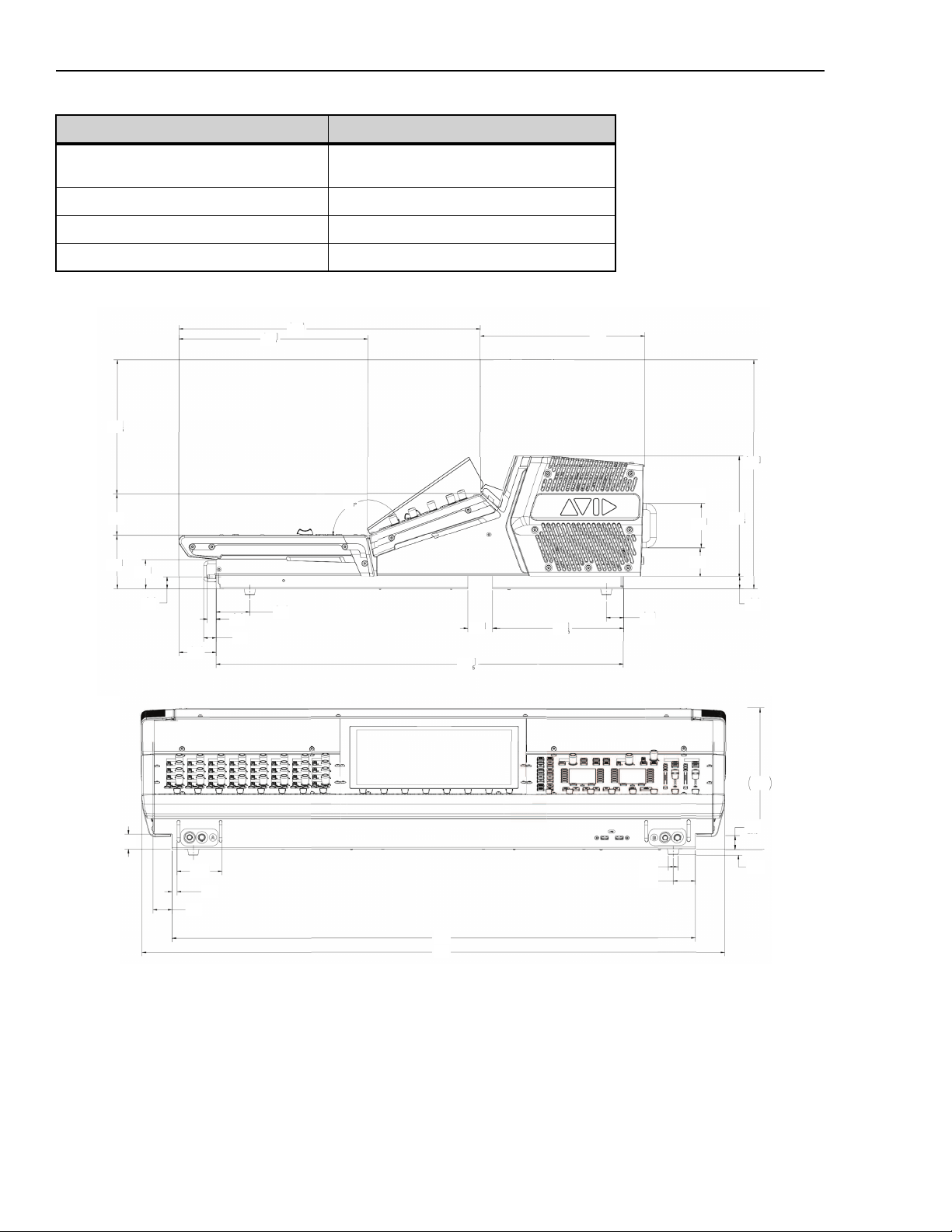
Mechanical Specifications 394
S6L-24C Control Surface
Parameter Specification
Maximum Height, Front
Maximum Height, Back
3.6 inches (92 mm)
8 inches (205 mm)
Maximum Width 38.9 inches (989 mm)
Maximum Depth 31 inches (787 mm)
Weight 84 lbs (38 kg)
S6L-24C Control Surface Dimensions
9.1
231
[ 1.0 ]
25.6
[ 3.0 ]
2x 76
[ .3 ]
2x 8.5
[ 34.8 ]
885
[ 38.8 ]
986
[ 1.4 ]
2x 36
[ .6 ]
4x ø16
[ .4 ]
4x 10
[ .8 ]
20.8
[ 9.1 ]
231
[ 1.3 ]
32.2
[ 20.0 ]
509
[ 12.5 ]
318.7
[ 8.9 ]
226.5
[ 2.7 ]
69.4
[ 3.6 ]
92
[ 2.0 ]
51.5
[ .8 ]
2.01
[ 2.5 ]
62.7
[ .6 ]
14.7
[ .8 ]
21
[ 2.2 ]
57
[ 1.7 ]
42
160º
[ 27.1 ]
688.5
[ 8.7 ]
221.5
[ 1.2 ]
29.3
[ .8 ]
21
[ 2.9 ]
74
[ 2.0 ]
49.8
[ 8.0 ]
204.5
[ 15.3 ]
388
[10.9]
277.7
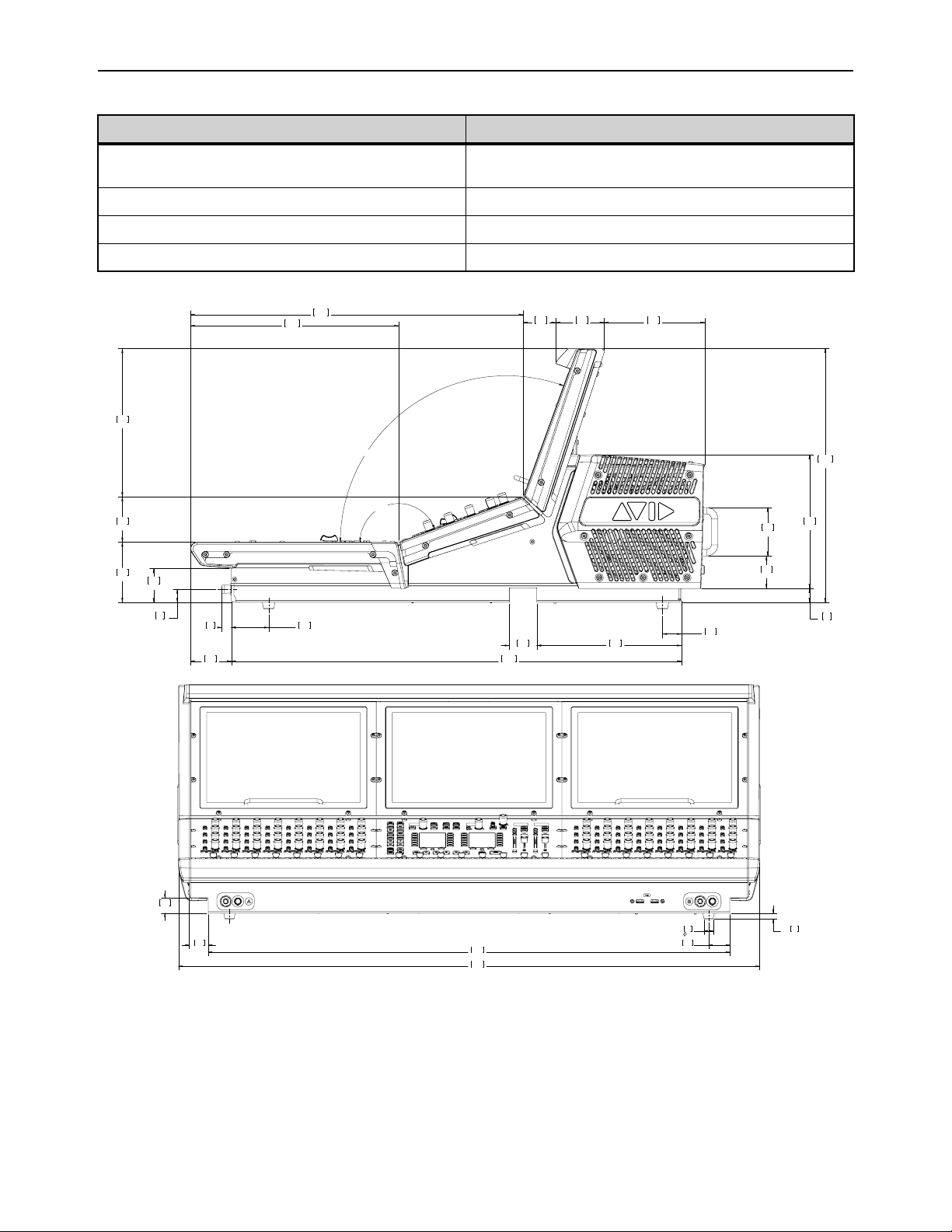
Mechanical Specifications 395
S6L-24/24D Control Surface
Parameter Specification
Maximum Height, Front
Maximum Height, Back
3.6 inches (92 mm)
15.3 inches (388 mm)
Maximum Width 38.8 inches (986 mm)
Maximum Depth 30.9 inches (786.5 mm)
Weight 119 lbs (54 kg)
.8
21
2.0
49.8
2.9
74
27.1
688.5
8.7
221.5
1.7
42
2.0
51.5
.6
14.7
2.5
62.7
3.6
92
2.7
69.4
8.9
226.5
12.5
318.7
20.0
509
6.0
153.7
2.9
74
2.0
50
160°
110°
8.0
204.5
15.3
388
.8
20.1
1.2
29.3
2.2
57
34.8
885
38.8
986
4X
.4
10
4X
.6
16
1.0
25.6
1.3
32.2
2X
1.4
36
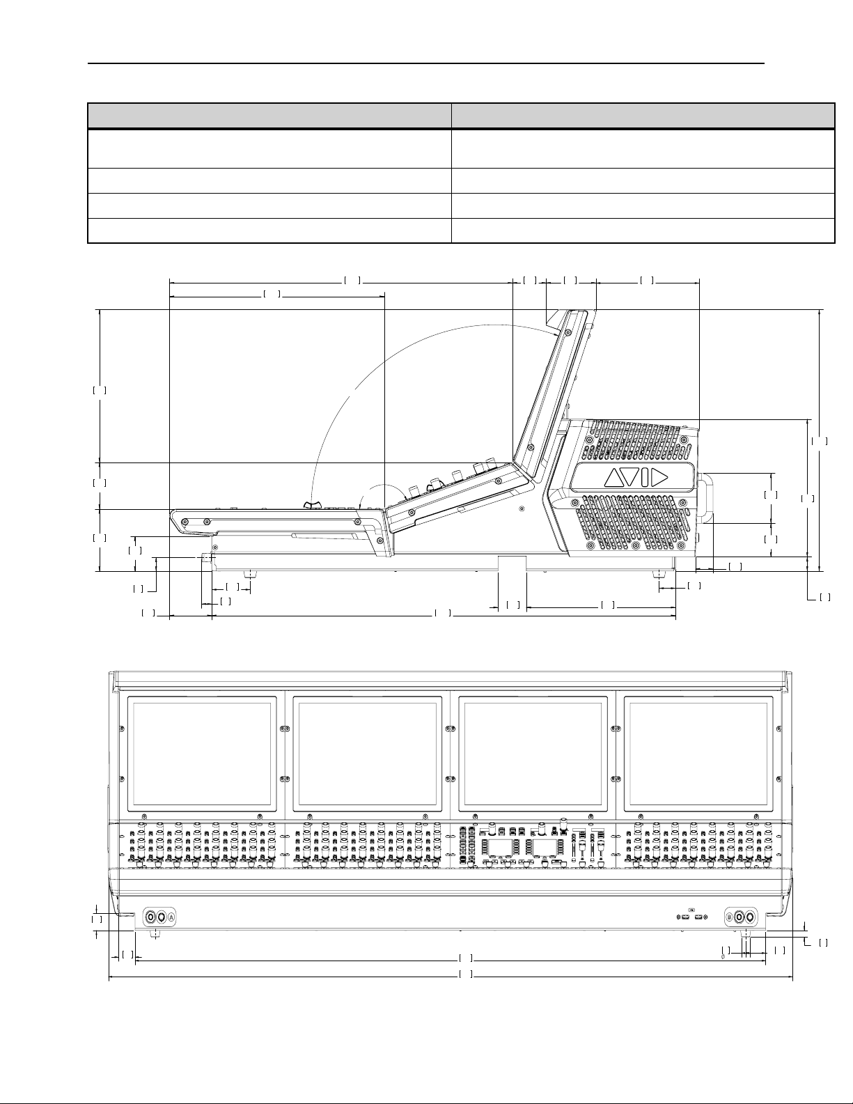
Mechanical Specifications 396
S6L-32D Control Surface
Parameter Specification
Maximum Height, Front
Maximum Height, Back
3.6 inches (92 mm)
15.3 inches (388 mm)
Maximum Width 51.2 inches (1302 mm)
Maximum Depth 30.9 inches (786.5 mm)
Weight 154.5 lbs (70 kg)
1.0
26
2.0
49.8
.8
21
8.7
221.5
1.7
42
8.0
204.5
15.3
388
2.0
51.5
3.6
92
2.5
62.7
.6
15
27.1
688.5
2.0
50
2.9
74
12.5
318.7
20.0
509
2.7
69.4
160°
110°
6.0
154
8.9
226.5
2.9
74
1.0
24.3
.8
20.1
2.2
57
4X
.6
16
4X
.4
10
47.2
1200
51.2
1302
1.0
25.6
1.3
32.2
4X
1.5
38
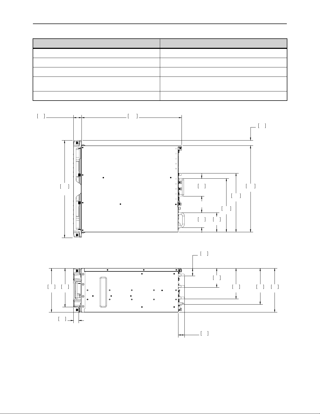
Mechanical Specifications 397
E6L Engine
Parameter Specification
Maximum Height 8.6 inches (218.7 mm)
Rack Spaces 5U
Maximum Width 19 inches (483.7 mm)
Depth with Bezel
Depth without Bezel
21.2 inches (537 mm)
19.6 inches (497 mm)
Weight 74 lbs (33.5 kg)
8.6
219
1.5
38.6
3.8
95.8
6.0
152.9
7.1
180.3
1.2
31.5
8.6
218.7
7.6
192.9
1.0
26.4
1.0
26.5
16.9
430
11.5
292.8
1.6
40.4
19.6
497
10.5
267.1
3.8
97.1
3.5
88
2.9
74
19.0
483.7

Mechanical Specifications 398
Stage 64
Parameter Specification
Maximum Height 17.5 in (444.5 mm)
Rack Spaces 10U
Width with Rack Ears
Width without Rack Ears
19 inches (483 mm)
17 inches (430.9 mm)
Maximum Depth 12.2 in (309.8 mm)
Weight Empty: 46 lbs (20.8 kg); Full: 69 lbs (31.2 kg)
19.0
482.6
17.5
444.5
17.0
430.9
12.2
309.8
[.6]
16.2
[.4]
10.4

Mechanical Specifications 399
Stage 32
Parameter Specification
Maximum Height 8.7 inches (221 mm)
Rack Spaces 5U
Width with Rack Ears
Width without Rack Ears
19 inches (483 mm)
17 inches (430.9 mm)
Depth 17.7 inches (448 mm)
Weight (Full) 49 lbs (22 kg)
Stage 32
221mm
8.7in
430mm
16.9in
448mm
17.7in
10mm
.4in
450mm
17.7in
15mm
.6in
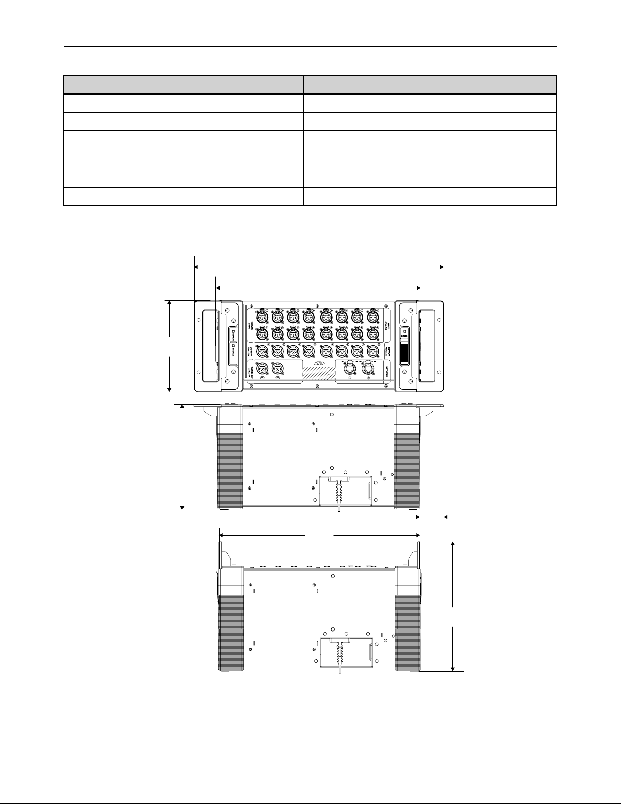
Mechanical Specifications 400
Stage 16
Parameter Specification
Maximum Height 6.9 in (175.2 mm)
Rack Spaces 4U
Width (with Rack Ears)
Width (Rack Ears configured as handles)
19 inches (483 mm)
15.6 inches (396 mm)
Depth (with Rack Ears)
Depth (Rack Ears configured as handles)
7.9 in (201 mm)
9.8 in (249 mm)
Weight 21 lbs (9.5 kg)
19 in
(483 mm)
1.8 in
(46.3 mm)
15.6 in
(396 mm)
15.3 in
(388.7 mm)
6.9 in
(175.2 mm)
7.9 in
(201 mm)
9.8 in
(249 mm)
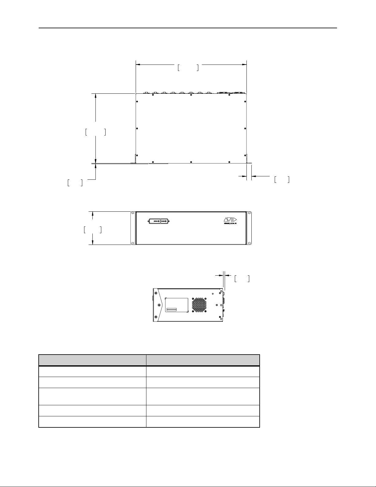
Mechanical Specifications 401
Local 16 I/O
Local 16
Parameter Specification
Maximum Height 5.2 inches (132 mm)
Rack Spaces 3U
Width with Rack Ears
Width without Rack Ears
19 inches (483 mm)
17 inches (430.9 mm)
Depth 11 inches (278 mm)
Weight (Full) 16.3 lbs (7.4 kg)
132.3mm
5.21in
278.3mm
10.96in
442.0mm
17.40in
20.3mm
.80in
1.6mm
.06in
5.8mm
.23in
Mechanical Specifications 402
S6L System Components LED Codes
E6L Engine
The Status and System LEDs on the E6L engine front panel light to indicate the following:
On E6L-112 (only), a flashing System LED indicates a disconnected AC power cable.
Stage 64 and Stage 32
Status LED
The STATUS LED on the Stage 64 lights to indicate status as follows:
Fault LED
The FAULT LED on the Stage 64 lights to indicate status as follows:
E6L engine front panel Status and System LEDs
LED Color State Description
Status
Green Solid All clear (no hardware alerts are detected).
Amber Solid
One or more hardware alerts are detected.
Consult the VENUE software Options > Devices page for detailed info.
Off (unlit) n/a E6L is powered off, or is initializing during startup.
System
Green Solid E6L is fully operational, and connected to the S6L control surface
Amber
Solid E6L processor has shut down; safe to power off E6L.
Flashing E6L processor is initializing.
Off (unlit) n/a E6L is powered off, or is initializing during startup.
Power and fan faults are also communicated on-screen via a warning dialog box on the external VENUE software screen.
Stage 64 Status LED
LED Color Description
Green solid Initialization is complete and the device is ready to pass audio.
Green flashing A firmware update for the device is in progress. No audio passes during a firmware update.
Stage 64 Fault LED
LED Color Description
Red solid Fan failure. Power cycle the device.
Red flashing Power supply temperature alert. This may indicate that the device is overheating. Power
down the device and check that the device is properly ventilated.
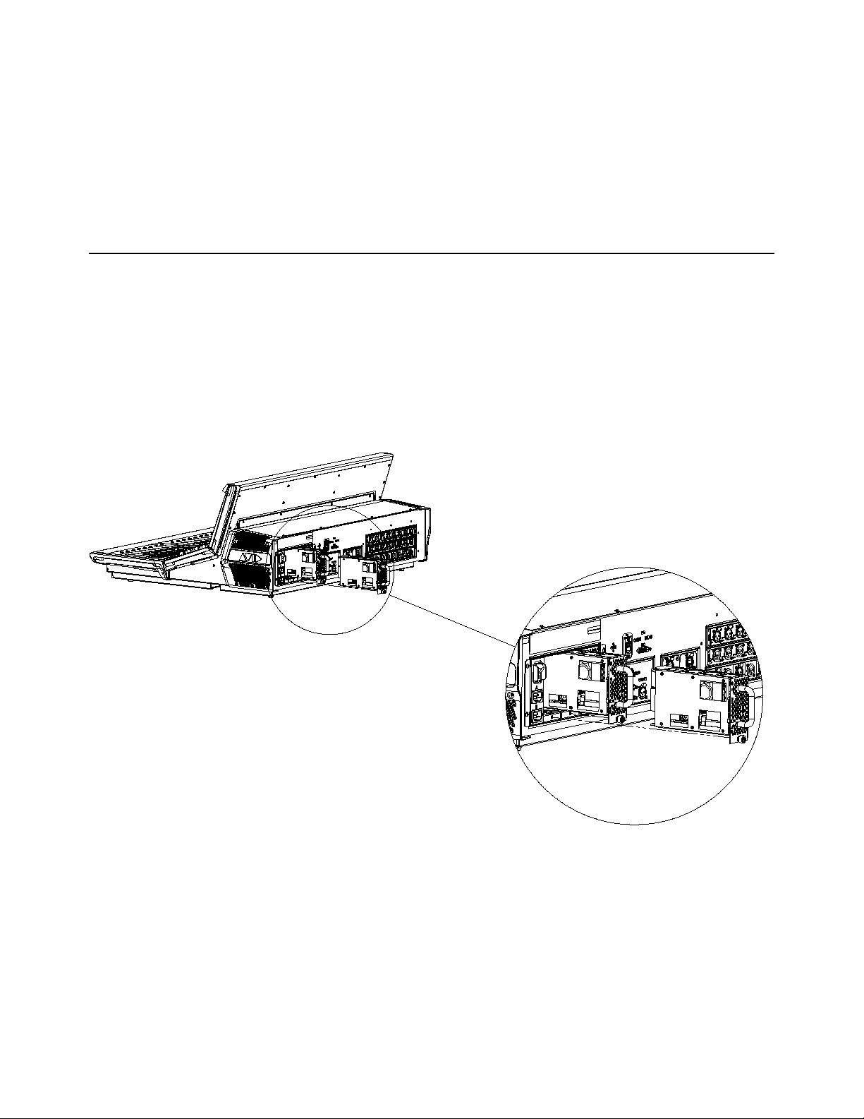
Mechanical Specifications 403
Network Port Act and Sig LEDs
Each S6L control surface, E6L engine, and Stage 64 Network port has its own Activity (Act) and Signal (Sig) LEDs. Each device
is ready for use when the Act and Sig LEDs are lit solid for each connected Network port.
Act LED
The Act (activity) LED lights solid to indicate that AVB Ethernet traffic is currently active on the connected audio snake
cable. If a redundant snake is connected, or if a Stage 64 is daisy-chained to another Stage 64, then ports A and B Act LEDs will
be lit.
Sig LED
The Sig (signal) LED lights solid to indicate that a valid communication connection exists between devices. If a redundant
snake is connected, or if the Stage 64 is daisy chained to another Stage 64, then ports A and B Sig LEDs will be lit.
Replacing S6L and E6L PSUs
The S6L-32D and S6L-24D control surfaces, and the E6L-192 and E6L-144 engines use the same model of hot-swappable PSUs,
and the procedure for replacing a faulty PSU is the same for both units.
To replace an S6L or E6L PSU:
1 On the back panel of the S6L or E6L, locate the faulty PSU, indicated by a red or not-lit PSU ON LED
2 Locate the PSUs captive thumbscrew, and rotate counter-clockwise to loosen, using a #1 Phillips screwdriver if necessary.
3 Using the handle, slide the PSU out of the unit.
4 Slide the replacement PSU into the proper slot of the unit, and rotate the captive thumbscrew clockwise to tighten.
Removing PSUs from the S6L control surface
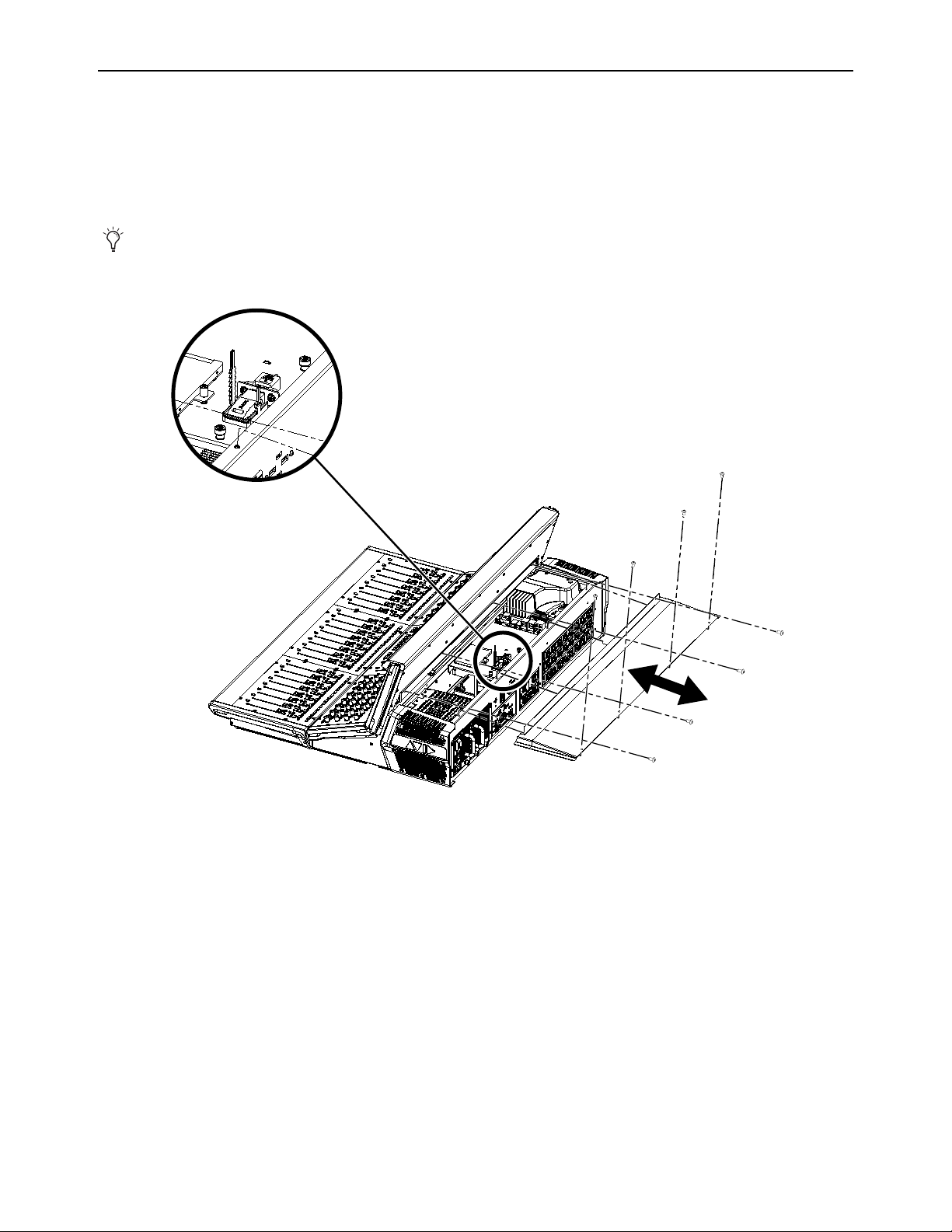
Mechanical Specifications 404
S6L Secure USB Port
The S6L control surface features a secure internal USB port to connect and securely protect an iLok containing plug-in licenses.
Use this port to keep one “master” iLok and its plug-in assets with the S6L control surface at all times, safe from damage or loss.
To access the port, the back cover of the S6L control surface must be removed. Only install the iLok after you have transferred
plug-in licenses to your iLok. See Installing and Authorizing Plug-Ins for more information on handling plug-in licenses.
A 2.5 mm hex wrench is required to remove the back cover.
To access the secure USB port in the S6L control surface:
1 Power down and disconnect all cables from the S6L control surface.
2 Using a 2.5 mm hex wrench, remove the 8 screws that secure the back cover of the control surface, as indicated in Figure 4, and
set the screws aside. (On S6L-16C, only, there are 6 screws to remove.)
3 Slide the panel away from the control surface, and set the panel aside. It may be necessary to loosen the end caps before the panel
can be removed.
4 Inside the control surface, locate the secure USB port and insert the iLok.
5 Secure the iLok with the built-in cable tie. Be careful to not over tighten the cable tie (make sure the iLok does not bend or sag).
6 Replace the top panel, making sure the left and right edges of the top panel are under the top edges of the side cover (where the
Avid logo appears) lips.
7 Reattach the eight screws removed earlier to secure the cover. If you loosened the end caps, be sure to re-tighten their screws.
The following image and instructions refer to an S6L-24D. The number of fasteners, and exact location of the secure USB
port, may differ with other models of S6L control surface.
Figure 4. S6L control surface secure USB port (S6L-24D shown)
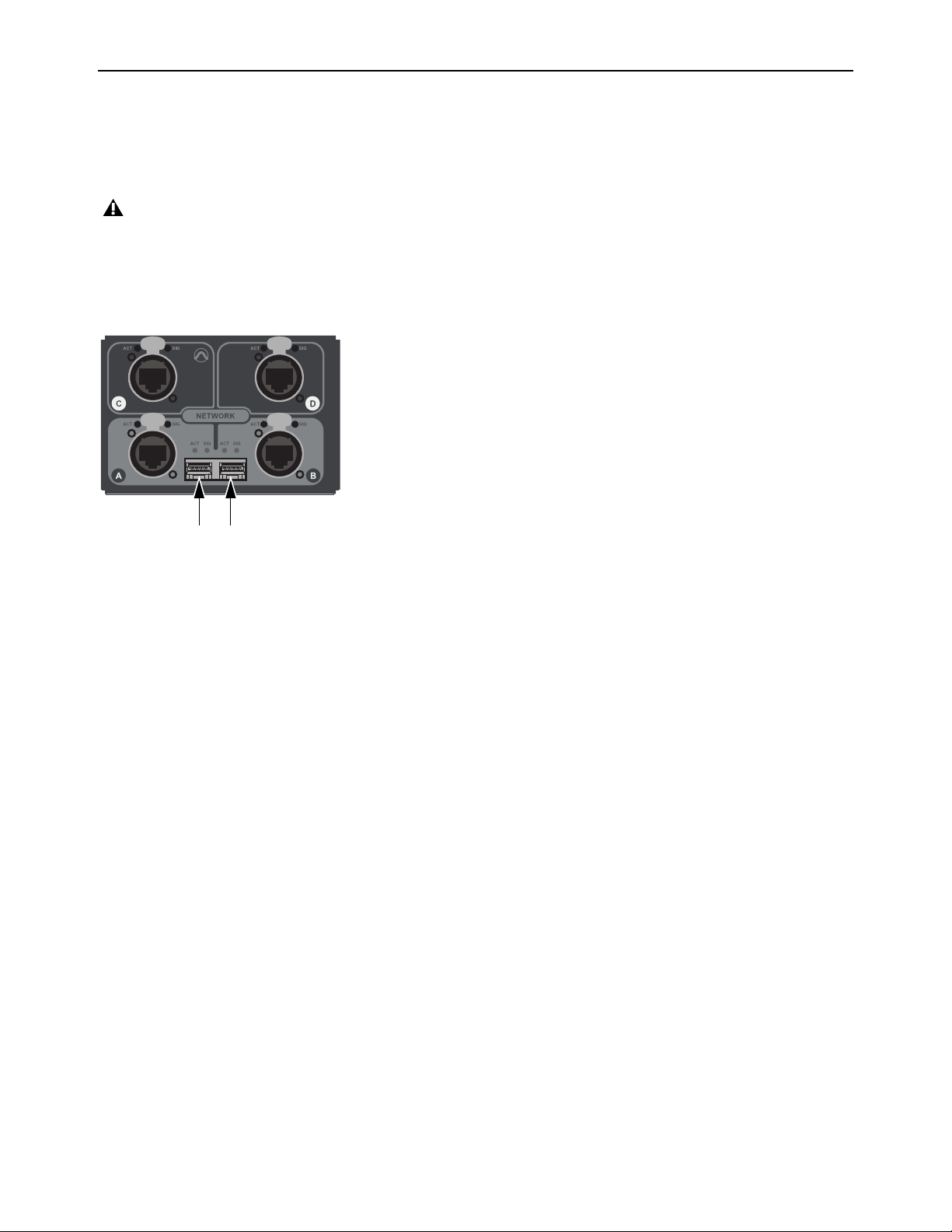
Mechanical Specifications 405
Making Fiber-Optic Connections
When using fiber to connect S6L system components, you must use two SFP qualified transceiver modules per connection in ad-
dition to supported fiber-optic cable (see Cabling Requirements for information on supported cabling). To make a fiber connec-
tions to an S6L system component, insert the SFP transceiver module into a fiber Network port of an S6L system component, and
then insert the fiber-optic cable into the SFP module.
To make a fiber-optic connection to an S6L system component:
1 Remove the dust plug from the desired fiber Network port on the S6L system component, and set it aside for later use.
2 Align the SFP module with the fiber Network port so that the release latch on the SFP module faces up (when installing in the
S6L control surface or the E6L engine), or to the left (when installing in a Stage 64).
3 Insert the SFP module into the port until you feel the module snap into place inside the port.
4 Remove the dust plug from the SFP module’s port, and set it aside for later use.
5 Remove the dust cap from the fiber-optic cable connector, align the connector with the port so that the tab on the top of the cable
connector faces up (when installing in the S6L control surface or the E6L engine), or to the left (when installing in a Stage 64),
and then insert the cable into the SFP module until you feel the cable connector snap into place.
To remove the fiber-optic cable from the SFP module:
1 Press the tab on the top on the cable connector to release the cable, and then pull the cable out of the SFP module.
2 Replace the dust cap on the end of the fiber-optic cable connector.
To remove the SFP module from the fiber port:
1 Pull the release latch on the SFP module out and down to release the module from the port, using a small flat head screwdriver
if necessary.
2 Pull the module out of the port.
3 Replace the dust plug on the SFP module port and place the module in an anti-static bag.
It is recommended that you do not install or remove an SFP module with a cable attached to it, or install or remove an SFP
module more often than is necessary. Always cover fiber-optic ports and connector ends when they are not connected using
dust caps and plugs.
Fiber Network ports A (left) and B (right) on the S6L control surface (dust plugs removed)
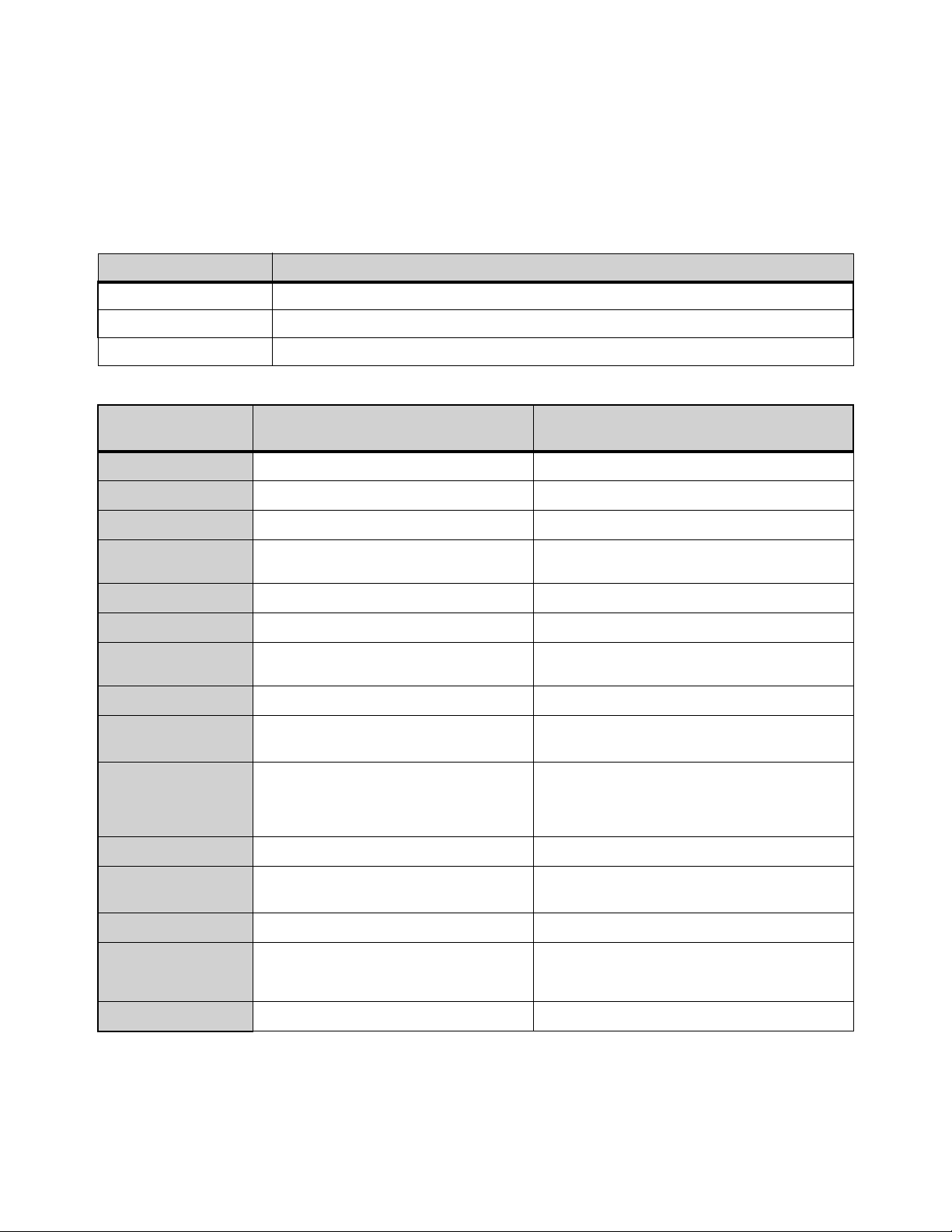
Audio Specifications 406
Audio Specifications
All specifications subject to change.
System Processing
Parameter Value
Internal Sample Frequency 96 kHz
Internal Processing Up to 64-bit floating point
Processing Delay
2.83 ms (Stage 64 analog input, through Mains L-R bus to Stage 64 analog output)
Analog Mic/Line Inputs
Parameter
S6L Control Surface Analog Inputs
(XLR)
SRI-192 Analog Input Card
Connector
8 XLR-F 8 XLR-F
Sample rate
96 kHz 96 kHz
Phantom Power
+48V +48V
Input Sensitivity
+14 dBu (+/-0.25 dB) @1 kHz, Pad Off
+34 dBu (+/-0.25 dB) @1 kHz, Pad On
+14 dBu (+/-0.25 dB) @1 kHz, Pad Off,
+34 dBu (+/-0.25 dB) @1 kHz, Pad On
Pad Depth
20 dB (+/- 0.25 dB), 1 kHz, 50 Ohm 20 dB (+/- 0.25 dB), 1 kHz, 50 Ohm
Gain Accuracy
±0.25 dB @ all gains ±0.25 dB @ all gains
Gain
+ 1 0 d B t o + 6 0 d B P a d O f f
–10 dB to +40 dB Pad On
+10 d B to +60 dB Pad Off,
–10 dB to +40 dB Pad On
Input Impedance
~4 k Ohms ~4 k Ohms
Frequency
Response
20 Hz - 20 kHz -0.2 dB @ all gains 20 Hz - 20 kHz ±0.1 dB @ all gains
THD+N
<0.0004% @+2 dBu, @1 kHz, @20 dB gain,
20 Hz-20 kHz filter,
<0.0005% 20-20 kHz, @+10 dBu, @10 dB gain,
20 Hz-20 kHz filter
<0.0004% @+2 dBu, @1 kHz, @20 dB gain,
20 Hz-20 kHz filter,
<0.0005% 20-20 kHz, @+10 dBu, @10 dB gain,
20 Hz-20 kHz filter
EIN
–127 dB, 150 Ohm source, 20 Hz - 20 kHz –127 dB, 150 Ohm source, 20 Hz - 20 kHz
Converter Group
Delay
12.6/Fs = 0.131 ms 12.6/Fs = 0.131 ms
Dynamic Range
>118 dB, A - weighted @ 1 kHz >118 dB, A - weighted @ 1 kHz
CMRR
>60 dB @60 Hz
>80 dB Typical, @100 Hz, 20 dB gain
>70 dB Typical, 20 Hz-20 kHz, 20 dB gain
>60 dB @60 Hz
>90 dB Typical, @100 Hz, 20 dB gain
>80 dB Typical, 20 Hz-20 kHz, 20 dB gain
LEDs
Signal Present (green), +48V (red) Signal Present (green), +48V (red)
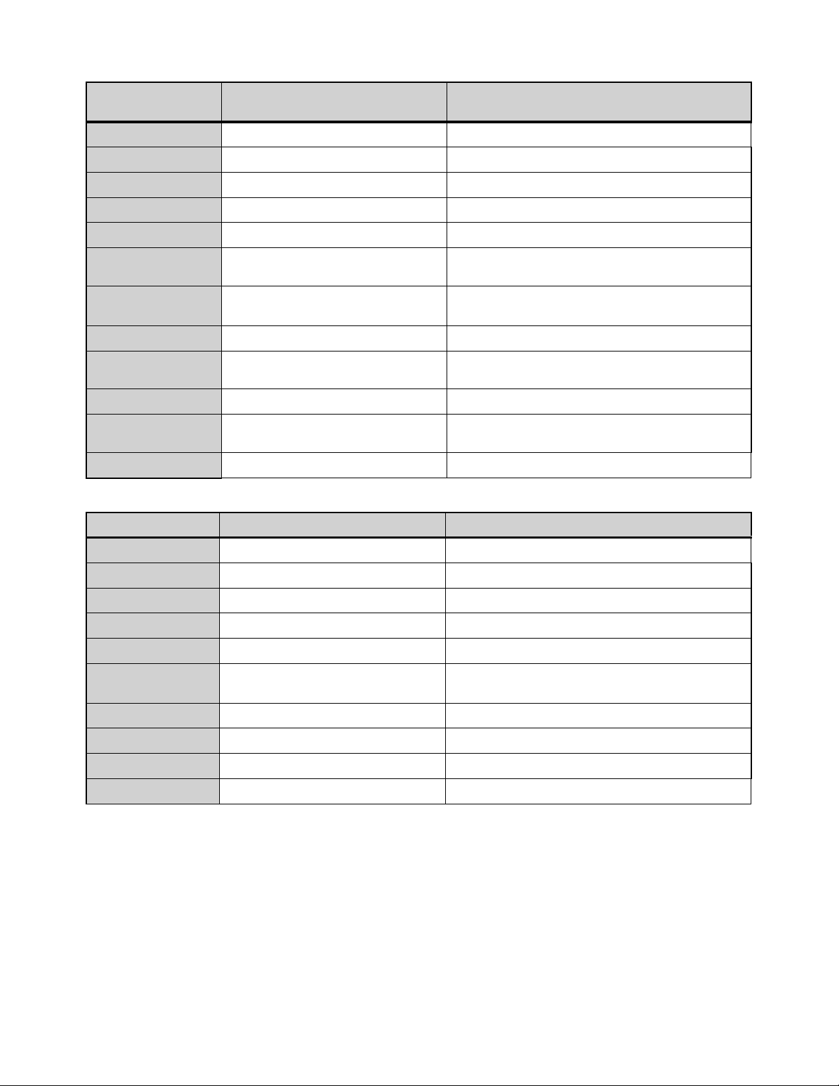
Audio Specifications 407
Analog Line Outputs
Parameter
S6L Control Surface Analog Outputs
(XLR)
SRO-192 Analog Output Card
Connector
(8) XLR-M (8) XLR-M
Sample rate
96 kHz 96 kHz
Output Sensitivity
+24 dBu (+/-0.25 dB) @1 kHz, 100 k ohm +24 dBu (+/-0.05 dB) @1 kHz, 100 K ohm
Gain Accuracy
±0.25 dB, 20-20 kHz, all gain settings ±0.25 dB, 20-20 kHz, all gain settings
Frequency Response
20-20 kHz, –0.15 dB –0.1 dB, 20-20 kHz
THD+N
<0.0005% @1 kHz, –5 dBFS
<0.0005%, 20-20 kHz, @–5 dBFS
<0.0006% @1 kHz, –5 dBFS
<0.0008%, 20-20 kHz, @–3 dBFS
Converter Group
Delay
7/Fs = 0.073 ms 7/Fs = 0.073 ms
Dynamic Range
>117.5 dB, A-weighted @1 kHz >116 dB, A-weighted @1 kHz
Mute Depth
>125 dB @1 kHz, @–10 dBFS
>115 dB 20-20 kHz, @–10 dBFS
>125 dB @1 kHz, @–10 dBFS
>115 dB 20-20 kHz, @–10 dBFS
Output Impedance
100 Ohms Differential 100 Ohms Differential
Crosstalk
>120 dB @1 kHz, @–10 dBFS
>100 dB 20-20 kHz, @–10 dBFS
>120 dB, @1 kHz, @–10 dBFS
>100 dB, 20-20 kHz, @–10 dBFS
LEDs
Signal Present, Mute Signal Present (green), Mute (red)
S6L Control Surface Digital I/O
Parameter S6L Control Surface Digital Inputs S6L Control Surface Digital Outputs
Connector
(4) XLR-F (4) XLR-M
Format AES 3 (AES/EBU) AES 3 (AES/EBU)
Word Length 24-bit 24-bit
Termination 110 Ohms 110 Ohms
Max Cable Length 328 feet (100 meters) 328 feet (100 meters)
Supported Sample
Rates
24 kHz to 210 kHz per input pair
(SRC is always active)
96 kHz
Level n/a ~3.6V pp maximum (i.e., +/- 1.8V)
Channel Status Info n/a Pro Audio 96 kHz, No Emphasis
Dithering n/a No
LEDs
n/a Signal Present (green), Mute (red) per AES pairs
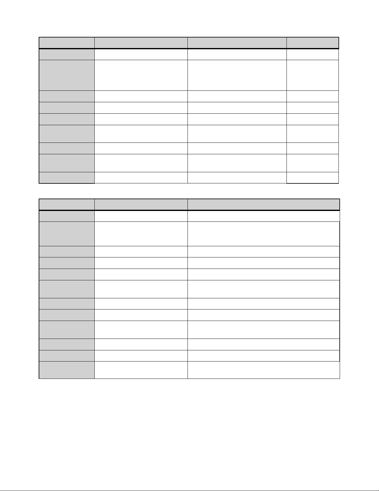
Audio Specifications 408
DSI-192 Digital Input Card
Parameter AES Digital Inputs ADAT Digital Inputs Word Clock Out
Connector
(4) XLR-F TOSLINK Optical BNC-F
Format AES 3 (AES/EBU)
ADAT, 8-channel @ 48 kHz,
4 channels @ 96 kHz,
2 channels @ 192 kHz
(selectable within software)
Word Clock Out
Word Length 24-bit 24-bit n/a
Termination 110 Ohms 110 Ohms n/a
Max Cable Length 328 feet (100 meters) n/a n/a
Supported Sample
Rates (with SRC)
24 kHz to 210 kHz per input pair
(defeatable within software)
24 kHz - 210 kHz n/a
Source Impedance n/a n/a 75 Ohm
Drive Level n/a n/a
2.5 pk-pk into
75 Ohm load
LEDs
Lock, SRC On Lock, SRC On
n/a
DSO-192 Digital Output Card
Parameter AES Digital Outputs ADAT Digital Outputs
Connector
(4) XLR-M TOSLINK Optical
Format AES 3 (AES/EBU)
ADAT, 8-channel @ 48 kHz,
4 channels @ 96 kHz,
2 channels @ 192 kHz
Word Length 24-bit 24-bit
Termination 110 Ohms 110 Ohms
Max Cable Length 328 feet (100 meters) n/a
Supported Sample
Rates
96 kHz
48 kHz SMUX, 96 kHz SMUX and 192 kHz SMUX
(selectable within software)
LEDs Lock, SRC On Lock, SRC On
Impedance 110 Ohm n/a
Level
~3.6 Vpp maximum
(i.e., +/- 1.8V)n/a
n/a
Channel Status Info Pro Audio 96 kHz, No Emphasis n/a
Dithering NO No
LEDs
Signal Present (green), Mute (red) per
AES pairs
Signal Present
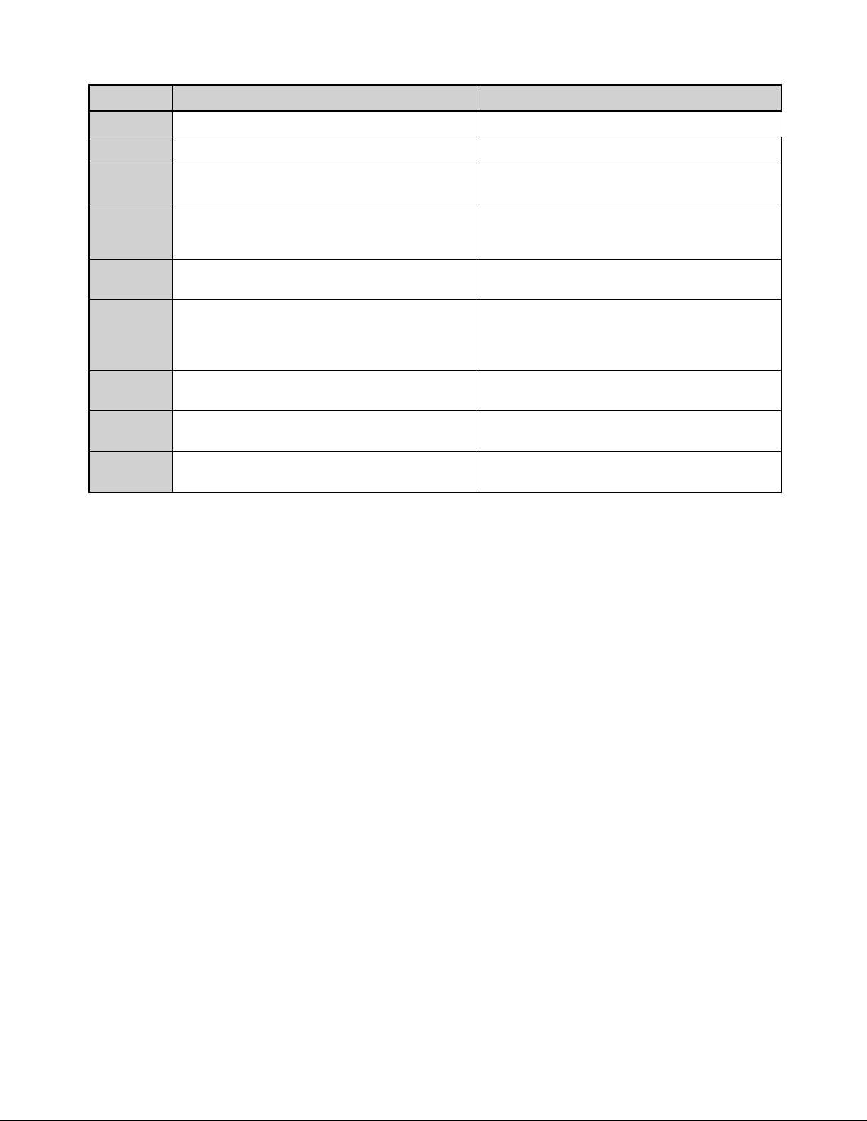
Audio Specifications 409
Headphone Outputs
Parameter
S6L Console Headphone Outputs Stage 64 Headphone Output
Connector
(2) TRS-F (1) TRS-F
Sample rate 48 kHz, 96 kHz, 192 kHz 48 kHz, 96 kHz, 192 kHz
Output
Impedance
<3 Ohms <3 Ohms
Max Output
Power (rms)
>600 mW, 32 Ohm, 1 kHz, 1% THD,
>190 mW, 300 Ohms, 1 kHz, 1% THD,
>100 mW, 600 Ohms, 1 kHz, 1% THD
>750 mW, 32 Ohm, 1 kHz, 1% THD,
>330 mW, 300 Ohms, 1 kHz, 1% THD,
>190 mW, 600 Ohms, 1 kHz, 1% THD
Frequency
Response
20-20 kHz, +/- 0.2 dB, –15 dBFS 20-20 kHz, +/- 0.1 dB, –15 dBFS
THD+N
<0.0007%, 1 kHz, –2 dBFS, >300 ohms,
<0.0025%, 20-20 kHz, -5 dBFS, 300 ohms, 20 kHz filter,
<0.0015%, 1 kHz, -5 dBFS, 32 ohms,
<0.0025%, 20-20 kHz, -4 dBFS, 32 ohms, 20 kHz filter
<0.0005%, 1 kHz, 0 dBFS, >300 ohms,
<0.0008%, 20-20 kHz, 0 dBFS, >300 ohms, 20 kHz filter,
<0.0008%, 1 kHz, -4 dBFS, 32 ohms,
<0.0015%, 20-20 kHz, -4 dBFS, 32 ohms, 20 kHz filter
Group
Delay
7/Fs = 0.073 ms 7/Fs = 0.073 ms
Dynamic
Range
>110 dB, 20-20 kHz, A-weighted >110 dB, 20-20 kHz, A-weighted
Channel
Separation
<–90 dB, 1 kHz, 600 Ohms <–90 dB, 1 kHz, 600 Ohms
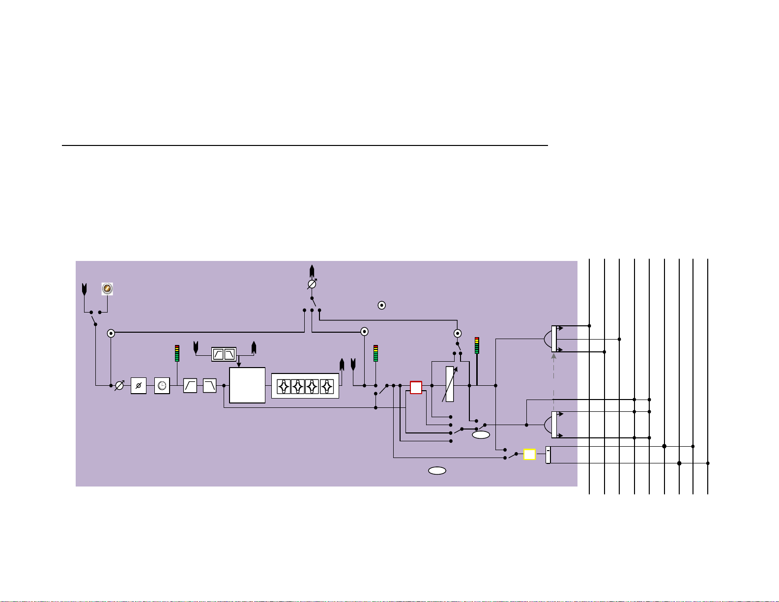
Signal Flow Diagrams
410
Signal Flow Diagrams
Input Channel Signal Flow
m
L
R
L
R
C
Input channel (Mic/Line)
Gain
trim
Phase
HPF
4-ba nd PE Q
Left
Right
Center
Groups
Mon Bus A - L
HW/SW
Insert
Mic/Line
Input
Fader
Mute
Key In
SC f ilte rs
Pre-EQ
AFL
Pre-EQ-Po st-M ute
SC listen
Pre-Mute
Pre-Fader
PRE
Botto m pickoff
select
Dyn
CompLim
+
ExpGate
To LCR
Can Follow Main
Pan
To Grp/Aux
(M)
(S)
Auxes
Input
dir ect
Pre/Post pickoff
Dir Out gain
Dir Out
pickoff select
Dir Out
InsRet pickoff
TOC pickoff
Mtx source out pickoff/
Pa tchb ay /Sid echa in
source
Pan
L
R
s
Mon Bus A - R
ProTo ols
Input
Per each bus
PRE
Solo
PFL
TOC
meter
InsRet
meter
PostFader
(pre-Mute)
meter
Mon Bus B - L
Mon Bus B - R
LP F
User
Delay
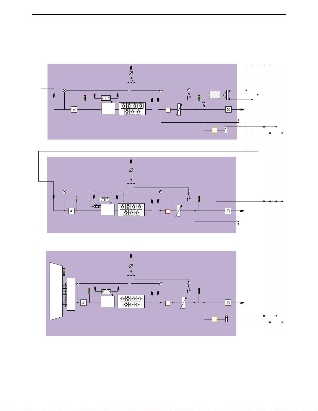
Signal Flow Diagrams 411
Output Channel Signal Flow
Mon Bus A (AFL) - R
Left
Right
Center
Grp/ mus sub xuA
slennahc tupni morf
Bus out
Dyn
Comp/
Lim
m
L
R
C
Group/Aux Output Channel
TOC pickoff
Fader
Mute
Solo/AFL
InsRet pickoff
Pre/Po st p icko ff
Mtx src
ou t
pickoffs
L
R
s
If Stereo
To LCR
Phase
User
Delay
Bottom pickoff
select
Dir O ut gain
Dir O ut
pickoff select
Dir O ut
Dyn
Comp/
Lim
m
L-R/C-Mono (Mains)
Channels
7-ba nd PE Q
TOC pickoff
Fader
Mute
InsRet pickoff
Pre/Post pickoff
Phase
Bottom pickoff
select
Dir O ut gain
Dir O ut
pickoff select
Dir O ut
Dyn
Comp/
Lim
m
7-ba nd PE Q
TOC pickoff
Fader
Mute
Solo/AFL
InsRet pickoff
Pre/Post pickoff
L
R
s
If Stereo
Phase
Bottom pickoff
select
Dir O ut gain
Dir O ut
pickoff select
Dir O ut
Bus out
Matrix Mixer Output Channel
Bus out
Mon Bus A (AFL) - L
User
Delay
User
Delay
Pan
GEQ->HW/SW
Insert
Po s t-F ad er
Pre-Fader
Post-Fader
Pre-Fader
LR st-linked
24x1/
16x1
mixer
Matrix
Input
Pool
Key In
SC f ilters
Key In
SC f ilters
SC listen
Key In
SC f ilters
SC listen
SC li ste n
LCR
de l ay
comp
PostFader
meter
TOC
meter
TOC
meter
PostFader
meter
TOC
meter
PostFader
meter
Matrix In pu t Po ol – A set of 256 unique (max), dynamically assignable sources from
all inp ut cha nn els, an d al l Gr ou p/Au x an d LC R bu sses, ava i lable to all matrix mixe rs .
Mon Bus B (AFL) - L
Mon Bus B (AFL) - R
Mix To Monitors
7-ba nd PE Q
Mtx src
meters
GEQ->H W/SW
Insert
GEQ->HW/SW
Insert
Mtx src
ou t
pickoffs

Part VII: Appendices

413
Important
(Model: S6L24, S6L32, E6L, and Stage 64)
Environmental Compliance
Disposal of Waste Equipment by Users in the European
Union
This symbol on the product or its packaging indicates that this product must not be
disposed of with other waste. Instead, it is your responsibility to dispose of your
waste equipment by handing it over to a designated collection point for the recy-
cling of waste electrical and electronic equipment. The separate collection and re-
cycling of your waste equipment at the time of disposal will help conserve natural
resources and ensure that it is recycled in a manner that protects human health
and the environment. For more information about where you can drop off your
waste equipment for recycling, please contact your local city recycling office or the
dealer from whom you purchased the product.
Proposition 65 Warning
Perchlorate Notice
This product may contain a lithium coin battery. The State of California requires the
following disclosure statement: “Perchlorate Material – special handling may ap-
ply, See www.dtsc.ca.gov/hazardous waste/perchlorate.”
Recycling Notice
EMC (Electromagnetic Compliance)
Avid declares that this product complies with the following standards regulating
emissions and immunity:
• FCC Part 15 Class B
• EN 55022 Class B
• AS/NZS CISPR 22 Class B
• CISPR 22 Class B
• EN 55103-1, Class E2 and E3
• EN 55103-2, Class E2 and E3
• EN55024
FCC Compliance for United States
Australian Compliance
Canada ICES-003 Compliance
This Class B digital apparatus meets all requirements of the Canadian Interfer-
ence-Causing Equipment Regulations.
Cet appareil numérique de la classe B respecte toutes les exigences du Règle-
ment sur le material brouilleur du Canada.
Korea Class B EMC Compliance
이 기기는 가정용 (B 급) 전자파적합기기로서 주 로 가정에서 사용하는 것을 목적
으로 하며 , 모 든 지역에서 사용할 수 있습니다 .
CE Compliance
(EMC, Safety and RoHS)
Avid is authorized to apply the CE (Conformite Europenne) mark on this compliant
equipment thereby declaring conformity to EMC Directive 2004/108/EC, Low Volt-
age Directive 2006/95/EC and RoHS Directive 2011/65/EC.
This product contains chemicals, including lead, known to the State of Califor-
nia to cause cancer and birth defects or other reproductive harm. Wash hands
after handling.
Communication Statement
NOTE: This equipment has been tested and found to comply with the limits for
a Class B digital device, pursuant to Part 15 of the FCC Rules. These limits are
designed to provide reasonable protection against harmful interference in a res-
idential installation. This equipment generates, uses, and can radiate radio fre-
quency energy and, if not installed and used in accordance with the instructions,
may cause harmful interference to radio communications. However, there is no
guarantee that interference will not occur in a particular installation. If this equip-
ment does cause harmful interference to radio or television reception, which can
be determined by turning the equipment off and on, the user is encouraged to try
and correct the interference by one or more of the following measures:
• Reorient or locate the receiving antenna.
• Increase the separation between the equipment and receiver.
• Connect the equipment into an outlet on a circuit different from that to
which the receiver is connected.
• Consult the dealer or an experienced radio/TV technician for help.
Any modifications to the unit, unless expressly approved by Avid, could void the
user's authority to operate the equipment.
Avid Technology, Inc.

Index 414
Numerics
0 dBVU 293
48V 113
A
A Device Has Been Lost 382
A Unit has gone Offline 385
Absolute (editing snapshots) 233
Actions 306
creating 315
list 324
ADAT I/O (on the DSI-192 and DSO-192 Digital I/O cards) 358
AFL 162
AND (Event List) 312
Assigning channels to outputs
external screen 200
from the control surface 107
Attentioning channels 102
from the control surface 102, 183
from the external screen 183
attentioning multiple channels 105
automation
Automation Safe 258
see Snapshots
Aux Mon/Aux FX 246
Aux User Presets
using 249
Auxes
adjusting Aux Sends 145
classifying Aux Sends as monitor or FX sends for snapshots
246
configuring 78
configuring monitoring options 163
enabling Sends on Faders mode 163
Expanded Aux view 146
spill 89
User Aux Scope (snapshots) 247
VCAs Trim Aux Sends in SOF 144
Avid
address 420
support resources 13
B
backup
Show file automatic backup 211
Show files and settings to a USB drive 208
Balance 194
balance (when pasting) 191
banking
banking only certain types of channels (Fader Bank Mode) 88
input channels in split banking mode 86
Mains 131
outputs in split banking mode 87
User Layout 93
banner display 179
Blank Strip 195
bus processing
adjusting bus-fed plug-ins 126
assigning a bus-fed plug-in 286
inserting Graphic EQs 187
routing a plug-in as a bus processor 288
Busses page 333
bypassing plug-ins 283
C
Cabling
requirements 12
Cannot assign Stage 64 380
center divergence 334
Center Last Recalled Snapshot 217
channel
reset shortcut 185
Channel Control
Channel Control Mode 23
Function Switches 24
User assignment 127
channel delay 113
channel EQ
adjusting using the control surface 118
adjusting using the external screen 186
Channel Safe Switch/Button
solo safing using 168
Channel Safe Switches/Buttons
automation safing using 258
bank safing using 97
safing from Recall Safe tab 255
setting the Chanel Safe Switch/Button Safe Mode 344
channels
copy and paste 191
in the Patchbay 264
moving 195, 197
Chase MTC/LTC 216
Child (snapshot) 221
cleaning and maintenance 11
Clear Console
during reset 332
clip
Hold 344
Margin 344
compatibility 12, 351
Config Mode
and assigning Stage 64s 68, 70
and loading Shows 205
and plug-ins 272
Console Connection Error 382
Control (Events) 303
Control surface controls have stopped working 380
Control Surface Module Lost 382
copy and paste
channel settings 191
dynamics settings 193
Index

Index 415
EQ settings 192
copying
plug-ins 285
creating an effect send/return 286, 288
crossfade
bypassing 246
crossfade time (snapshots) 245
CTM
overview 26
selecting a channel from 101
troubleshooting offline CTMs 385
cursor 341
D
Dante (DNT-192 Dante Network Card) 51
Date & Time Check 382
dBVU, dBu, dBFS 293
DC (GPI Output) 376
Default 29
delay
channel delay 113
Delay Compensation 335
Monitor bus 165
unit display setting 341
Delay Compensation 335
Devices page 346
digital inputs
defeating SRC 358
DSI-192 Digital Input card 51
on the control surface 42
digital outputs
on the control surface 42
on the DSO-192 Digital Output card 51
Digital/Analog EQ 186
dimensions 393
Direct Outs
adjusting 116
patching 267
routing to plug-ins 289
divergence 334
Dly (channel Delay in snapshots) 261
DSI-192 Digital Input Card
overview 51
DSI-192 Digital Input card
using 358
DSO-192 Digital Output Card
audio specifications 408
overview 51
DSP for plug-ins 292, 346
dynamics
adjusting from the control surface 122
adjusting using the external screen 188
copying and pasting settings 193
sidechain on the CKM 123
sidechain on the external screen 189
E
E6L engine
features 5, 46
front panel LED codes 402
mechanical specifications 397
powering on and pairing 62
Edit (System Config) 329
Edit mode 233
Effect Return 126
Encoder Assign 129
Engine Internal Switch Warning 382
EQ
channel EQ 118, 186
digital/analog 186
frequency from CKM 119
GEQ 187
settings and presets 192
Events
actions 306
and Preview mode 239
and Snapshot modes 318
and snapshots 318
behavior 316
creating actions 315
creating triggers 311
creating, selecting, managing 307
enabling and disabling 309
Event List 303
import 210
list of action types and properties 324
list of trigger types and properties 322
preset files 310
reset 317
terminology 302
testing 317
triggers 305
Wait 316
window 303
Expanded Aux view 146
F
Fault LED 402
feedback
avoiding event-created feedback loops 318
Fiber-Optic
cabling requirements 12
making connections 405
Filing
History 211
loading Shows 205
Presets and Scope Sets 206
Show files 204
Show Folders 203
Fine 29
momentary or latching 29
Fine mode for encoder parameter adjustment 29
Flex Channels
adjusting Mains on the Flex Channels 130
configuring 344
overview 33
Footswitch
connector 44
footswitch
Events triggers list 311
status display on the external screen 306
formats (plug-ins) 285
FX send/return 288
G
gate
adjusting using the control surface 122
adjusting using the external screen 188
key source 189
sidechain filters 124

Index 416
General Purpose Interface (see GPI)
GPI
input specifications 375
output specifications 376
pulse and duration 316
status display on the external screen 306
wiring diagrams 377
Graphic EQ
adjusting using the control surface 120
adjusting using the external screen 187
ground (GPI outputs) 376
Group (snapshots) 225
Groups
assign channels to using the external screen 200
assigning input channels to using the control surface 109
configuring 78
on-screen indication of stereo groups 194
spill 89
H
hardware inserts 372
Hardware Monitor Alert 382
HDX DSP card requires update 382
headphones
audio specifications 409
configuring 170
jacks 45
level 170
History 211
History (Show files) 211
HPF 115
I
iLok
authorizing plug-ins using 276
secure port for 404
Import
snapshots and events 210
input and output channels
adjusting using the control surface 106
make stereo 194
Input Direct mode 190
Input Safe Switches
changing modes via an Event 320
inputs
20 dB pad 113
assigning to Mains and Groups 107
banking 86
HPF 115
Input Direct mode 190
LPF 115
pan 114
phantom power 113
polarity (phase) 116
width 114
Insert Blank Strip 195
inserting external hardware on channels 372
inserts
assigning plug-ins 286
hardware inserts 372
installing
plug-ins 273
System Restore software 388
Interaction page 342
K
key assign 189
key listen 124, 190
key source 189
L
Latch (Event action behavior) 316
latching Solo on 166
latching to a Flex Channel 33
levels
plug-ins 293
listen wedge 165
locking snapshots 230
logic (GPI) 375
LPF 115
LTC
supported frame rates 363
M
MADI
MADI Outs, Stage 64 59
Mains 334
banking 131
configuring 77
configuring Main busses 77
input routing 107
Make Mono 194
Make Stereo 194
and Blank Strips 195
Master Live Module (MLM)
overview 28
Matrix
adjusting input (send) levels 149
linking and unlinking inputs 150
make a stereo Matrix 194
spill 89
mechanical specifications 393
Media (see Events) 303
Media Clock Master 355
metering
ballistics for meters 343
meter options 343
Meters view
selecting a channel from 101
MIDI
adding to snapshots 240
in Preview mode 239
MIDI Snapshot Output Safe 253
output Safe 242
triggering external devices on snaphsot recall 366
Misc page 338
Mix (Recall Safe parameters) 256
Mix Busses
configuring Auxes and Groups 78
Momentary (snapshots) 224
momentary Solo 166
Monitor
assignable output 165
Delay 165
level 170
mouse settings 341
move input channels
Move Selected Strip Here right-click command 195
using drag and drop 197
moving plug-ins 285

Index 417
MTC
generating MTC from VENUE (sending MTC to an external
device) 362
in Preview mode 239
supported frame rates
MTC/LTC
supported frame rates 363
MTC/LTC
chase 216
Events and Preview mode 239
MTS
attentioning channels from 102
basics of using 37
Multi-Assign 107
overview 37
selecting a channel from 101
troubleshooting 390
Multi-Assign
from the MTS 107
Multi-Select 104
on the external screen 183
using Attention 105
using Select 104
Mute
channel strip Mute switch 18
Mute Groups 156
Mute Groups tab 156
muting from the MTS 155
with VCAs 161
N
near field monitors
patching 165
Network ports
E6L engine 49
S6L control surface 43
Sig and Act LEDs 403
Stage 64 53
Notes
Show files 211
Snapshots 220
O
offset 112
One or more Engine fans have stopped working 382
One or More Units have Failed 382
operating modes (Config Mode and Show Mode) 67
Options 329
Busses 333
Devices 346
Interaction 342
Misc 338
Pickoffs 335
Snapshots 336
options 343
OR (Event List) 312
Other 285
outputs
banking in split banking mode 87
divergence 334
graphic EQ 187
patching/routing 266
reassigning in Patchbay 270
routing 267
P
pad 113
padlock (snapshots) 230
Pan 114
see also Width 114
pan
divergence 334
when pasting 191
parameters 153, 161
Parent (snapshot) 221
Patchbay
displays and indicators 264
navigating 264
overview 262
warning when reassigning 270
Patching Grid 263
Peak mode (metering) 343
PEQ 118, 186
PFL 162
phantom power 113
Pickoffs page 335
Plug-In Racks are Ready 388
Plug-In Racks Need Reset 382, 388
plug-ins 272
adjusting bus fed plug-ins (effect returns) using the control
surface 126
adjusting inserts using the control surface 125
and channel Direct Outs 289
and snapshots 291, 292
assigning to rack slots 284
Config and Show mode 272
display unavailable and inactive 282
DSP available 292, 346
enabling and disabling 276
in Preview mode 238
in/out (bypass) 283
indication of targeted plug-in in rack slot 281
list and menu management 276
managing 274
mono, stereo, other 285
moving and copying 285
pinning a view 281
preset files 291
rack slots 283
racks 278
re-initializing the racks 388
routing to and from 286
snapshot indication (red) 282
Use Racks 388
views 278
Waves 295
Plug-ins to Install 273
polarity (input) 116
Position Safe when Spilling 342
power
replacing control surface and engine PSUs 403
requirements 12
start up/shut down guidelines 62
Power supplies (PSUs)
E6L engine PSU description 49
replacing 403
requirements 12
S6L control surface PSU description 44
Pre (snapshot parameters) 246
Presets

Index 418
and plug-ins 291
presets
Aux User Scope 249
EQ 192
Events 310
folders 206
managing 207
plug-ins 291
Scope Sets 257
transferring 208
Preview mode 30, 236
and plug-ins 238
and Undo 237
capabilities and overview 237
MIDI and MTC 239
Propagate mode 234
Pulse and Duration (GPI) 316
Push-Pin (plug-in view) 281
Q
Quit 63
R
rack slots 278
racks 388
racks (plug-ins) 278
Recall 226
Next 215
Previous 215
Recall Safe
and Preview mode 237
Channel Safe 255
Matrix and PQ 256
using 255
red plug-in rack 282
Redundant Connection Lost 382
Relative (editing snapshots) 233
Reset 388
Reset (strip) 185
reset a section or parameter 29
resolution (see Fine)
Restoring the system software 388
restoring your system 388
RMS mode (metering) 343
routing
Monitor bus 165
multiple channels to a hardware output 269
S
S6L control surface
banking channels 84
features 2
hardware I/O 42
I/O audio specs 406
secure USB port for iLok 404
selecting and attentioning channels 100
troubleshooting control surface I/O 385
S6L control surface /O is not passing audio 380
Safe
Automation Safe 258
enabling in Channel Control mode 117
solo safe 168
Sample Rate Conversion
Alert 382
for digital inputs 358
save (History auto-save) 211
Scope Sets
transferring 208
using 257
Selecting channels 100
selecting multiple channels 104
Sends on Faders mode
enabling 163
using 141
settings
EQ 192
plug-ins 291
SFP transceiver modules
qualified modules 12
Shared Stage inputs
Working with outputs 127
shortcuts
Snapshots 216
Show files 203
creating 203
deleting 204
Folders 204
loading 205
transferring 208
Show Folder 204
Show Mode 67
Shows
and plug-in management while loading 276
shut down 63
side-chain
assigning for plug-ins 289
assigning source (gate only) 189
sidechain
adjusting from the CKM 123
adjusting from the external screen 189
SIP 162
Snapshots
adding MIDI messages 240
adding plug-in data 242
Center Last Recalled in list 217
Channel Safe 255
channel scope 218
chase MTC/LTC 216
classifying Aux Sends for snapshot recall 246
creating 220
crossfade time 245
data type buttons 218
Edit mode 233
Events and Preview mode 239
faders 219
Group 225
import 210
in Preview mode 237
keyboard shortcuts 216
List 215
list of data types and parameters 256, 261
locking and unlocking 230
managing (storing, clearing, deleting, moving, duplicating)
230
MIDI and plug-ins in Preview mode 237
Momentary 224
naming and renaming 220
notes 220
overview 213

Index 419
Parent and Child 221
plug-in menu 292
plug-in scope indication 282
Preview (editing and previewing snapshots) 30, 236
Propagate mode (updating snapshot parameters) 234
recalling 226
safe filter (Recall Safe) 255
Scope Sets 249, 257
selecting 216
snapshot color indication in Snapshots List 215
target 226
User Aux Scope 248
x-Fade 245
Snapshots page 336
software
overview of pages and tabs 175
Solo 168
AFL, PFL, SIP modes 162
and key listen 124, 190
momentary and latching modes 166
Solo and monitor options
configuring 162
Solo Safe 168
Soundgrid 295
Spill mode 89
Stage 16
about 8
configuring 79
Stage 32
about 7
Stage 64
Confidence Monitor 55
features 6
front panel LED codes 402
Identify and Mute switches 348
mechanical specifications 398, 399, 400, 401
reassigning 79
troubleshooting Stage 64 I/O 385
Status LED 402
stealing channels in the Patchbay 270
stereo
spread (Bal/Width) 194
stereo channels (see Make Stereo) 194
stereo effect return 194
stereo plug-ins 285
support resources 13
System Config 329
System LED 402
system requirements 12, 351
System Restore 388
System Restore Software 388
System Test 332
T
Tap Tempo
event 327
in Snapshots 244
switch 36
using 294
temperature
monitoring component temperatures 347
operational requirements 11
The 13, 162
Time Code Options 337
Touch on external screen is reversed with MTS, or not operating
at all 380
Trackball
settings for 341
transfer 208
triggering external devices with MIDI 366
Triggers 305
creating 311
list 322
Troubleshooting
Restoring the system software 388
troubleshooting
plug-ins 276
restoring your system 388
U
Undo
in Preview mode 237
via History 211
Unsupported HDX DSP configuration detected 382
USB ports
E6L engine front-panel ports 47
S6L control surface front-panel ports 45
secure internal port for plug-ins iLok 404
Use Racks 388
User Aux Scope 247
using 248
User Layout 90
Utility mode 387
V
VCAs
and snapshots 261
assigning 134
VCAs Trim Aux Sends in SOF 144
W
Wait (Event List) 316
Warning Dialogs 382
Waves 295
While Active (Event action behavior) 316
Width 114
width (when pasting) 191
Word Clock
I/O 49, 53
indication of 355
synchronizing with 353, 359
WSG-HD card 295
X
X-fade (crossfade) 245
XOR (Event List) 312

Technical Support (USA)
Visit the Online Support Center
at www.avid.com/support
Product Information
For company and product information,
visit us on the web at www.avid.com
Avid
75 Network Drive
Burlington, MA 01803