Owner’s Manual
Reliable Emergency Backup Power
Congratulations! You've purchased the most advanced, feature-rich Inverter/Charger designed as an alternative energy source during utility
power failures. Tripp Lite APS Inverter/Chargers keep your equipment up and productive through all utility power problems (blackouts,
brownouts and overvoltages) by inverting DC power from user-supplied batteries into AC power. When utility power is present, APS Inverter/
Chargers automatically pass through power to your equipment while simultaneously recharging your connected battery bank. Built-in surge
suppression provides an additional level of equipment protection. APS Inverter/Chargers are the quiet alternative to gas generators for emergency
backup applications. You get AC electricity anywhere and anytime you need it—with no fumes, fuel or noise!
Better for Your Equipment Premium Protection Levels
• Built-InISOBAR
®
Surge Protection
• AutomaticOverloadProtection
IdealOutputforAllLoads
• Frequency-ControlledOutput
• AutomaticLoadSwitching
• BalancedLoadSharing
Better for Your Batteries FasterBatteryRecharge
• High-Amp,3-StageBatteryCharger(adjustable)
Critical Battery Protection
• BatteryChargeConserver(LoadSense)
• BatteryTemperatureSensing
• High-EfficiencyDC-to-ACInversion
Better for You Quiet,Simple,Maintenance-FreeOperation
• Multi-FunctionLights&Switches
• Moisture-ResistantConstruction*
Safety 2
Feature Identification 3
Operation 4-5
Configuration 5-7
Battery Selection 8
Mounting 9
Battery Connection 10
AC Input/Output Connection 11
Service/Maintenance 11
Troubleshooting 12
Warranty/Warranty Registration 12
Español 13
PowerVerter
®
APS Series DC-to-AC
Inverter/Charger
Input Output
Invert: 12 VDC 120V, 60 Hz. AC
Charge: 120V, 60 Hz. AC 12 VDC
1111 W. 35th Street, Chicago, IL 60609 USA
Customer Support: 773.869.1234
www.tripplite.com
* Inverter/Chargers are moisture-resistant, not waterproof.
Copyright © 2009. All rights reserved. PowerVerter
®
and Isobar
®
are registered trademarks of Tripp Lite.
Contents
WARRANTY
REGISTRATION
Register online today for
a chance to win a FREE Tripp Lite
product! www.tripplite.com/warranty
2
Important Safety Instructions
SAVE THESE INSTRUCTIONS!
This manual contains important instructions and warnings that should be followed during the installation, operation and storage of this
product.
Location Warnings
• InstallyourInverter/Chargerinalocationorcompartmentthatminimizesexposuretoheat,dust,directsunlightandmoisture.
• AlthoughyourInverter/Chargerismoistureresistant,itisNOTwaterproof.Floodingtheunitwithwaterwillcauseittoshortcircuit
andcouldcausepersonalinjuryduetoelectricshock.Neverimmersetheunit,andavoidanyareawherestandingwatermight
accumulate. Mounting should be in the driest location available.
• Leaveaminimumof2"clearanceatfrontandbackoftheInverter/Chargerforproperventilation.ToavoidautomaticInverter/Charger
shutdown due to overtemperature, any compartment that contains the Inverter/Charger must be properly ventilated with adequate
outside air flow. The heavier the load of connected equipment, the more heat will be generated by the unit.
• DonotinstalltheInverter/Chargerdirectlynearmagneticstoragemedia,asthismayresultindatacorruption.
• Donotinstallnearflammablematerials,fuelorchemicals.
• Do not mount unit with its front or rear panel facing down (at any angle). Mounting in this manner will seriously
inhibit the unit's internal cooling, eventually causing product damage not covered under warranty.
Battery Connection Warnings
• TheInverter/Chargerwillnotoperate(withorwithoututilitypower)untilbatteriesareconnected.
• Multiplebatterysystemsmustbecomprisedofbatteriesofidenticalvoltage,age,amp-hourcapacityandtype.
• Becauseexplosivehydrogengascanaccumulatenearbatteriesiftheyarenotkeptwellventilated,yourbatteriesshouldnotbe
installed (whether for a mobile or stationary application) in a “dead air” compartment. Ideally, any compartment would have some
ventilation to outside air.
• Sparksmayresultduringfinalbatteryconnection.Alwaysobserveproperpolarityasbatteriesareconnected.
• DonotallowobjectstocontactthetwoDCinputterminals.Donotshortorbridgetheseterminalstogether.Seriouspersonalinjury
or property damage could result.
Equipment Connection Warnings
• Use of this equipment in life support applications where failure of this equipment can reasonably be expected to cause the
failure of the life support equipment or to significantly affect its safety or effectiveness is not recommended. Do not use this
equipment in the presence of a flammable anesthetic mixture with air, oxygen or nitrous oxide.
• OnlyconnectyourInverter/ChargertoaproperlygroundedACpoweroutletorhardwirepowersource.Donotplugtheunitintoitself;
this will damage the device and void your warranty.
• Youmayexperienceunevenperformanceifyouconnectasurgesuppressor,lineconditionerorUPSsystemtotheoutputofyour
Inverter/Charger.
Operation Warnings
• Your Inverter/Charger does not require routine maintenance. Do not open the device for any reason. There are no user serviceable parts inside.
• PotentiallylethalvoltagesexistwithintheInverter/Chargeraslongasthebatterysupplyand/orACinputareconnected.Duringany
service work, the battery supply and AC input connection (if any) should therefore be disconnected.
• DonotconnectordisconnectbatterieswhiletheInverter/Chargerisoperatingineitherinvertingorchargingmode.OperatingMode
SwitchshouldbeintheDCOFFposition.Dangerousarcingmayresult.
Caution: Your Inverter/Charger has a failsafe AC pass-through feature. The AC output will be live (if AC input is
available) even though the operating mode switch is set to DC OFF.
3
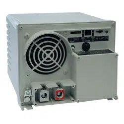
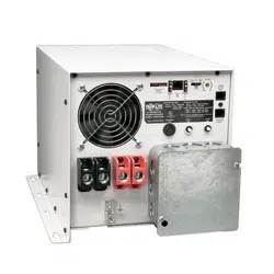
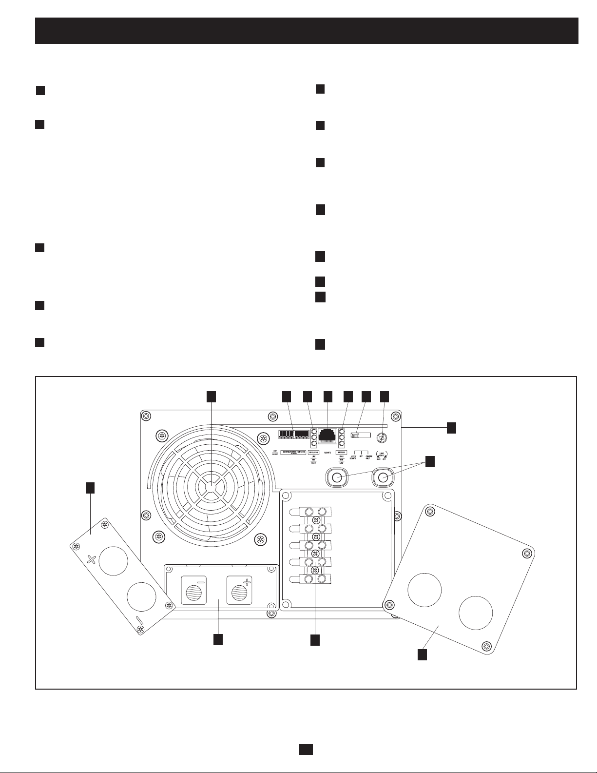
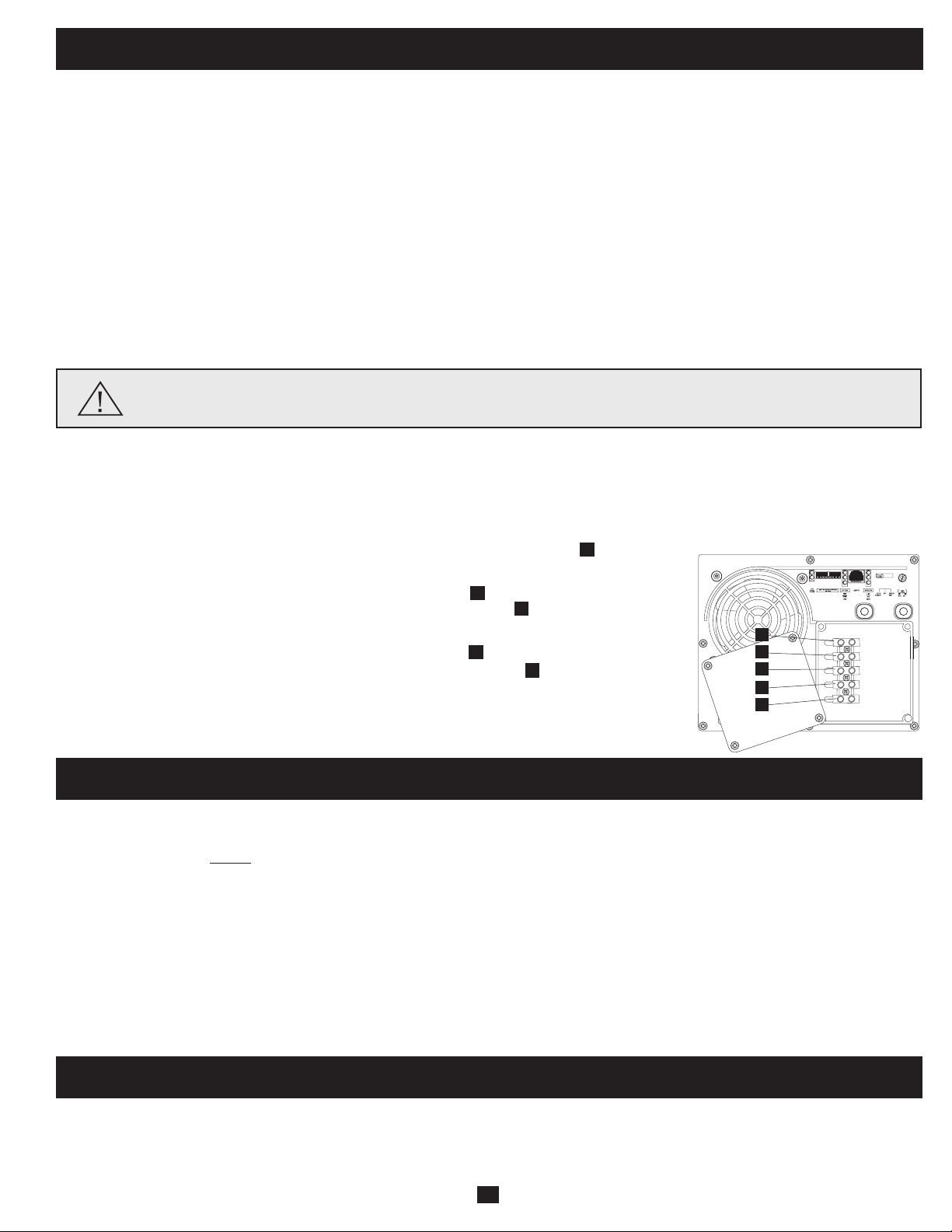
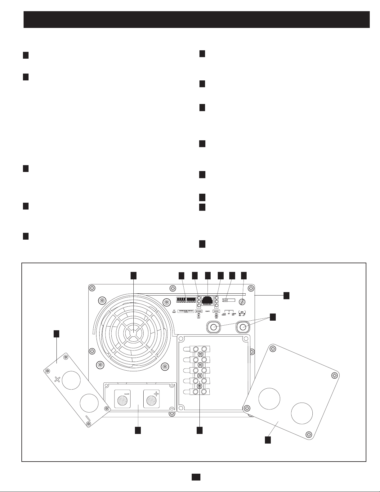
Feature Identification
Identifythepremiumfeaturesonyourspecificmodelandquicklylocateinstructionsonhowtomaximizetheiruse.
Configuration DIP Switches: optimize Inverter/Charger
operation depending on your application. See Configuration
section for setting instructions.
Operating Mode Switch: controls Inverter/Charger operation.
The “AUTO/REMOTE” setting ensures your equipment
receives constant, uninterrupted AC power. It also enables the
Inverter/Charger to be remotely monitored and controlled with
an optional remote module (Tripp Lite modelAPSRM4,sold
separately).The“CHARGEONLY”settingallowsyourbatteries
to return to full charge faster by turning the inverter off which
haltsbatterydischarging.SettingtheOperatingModeSwitchto
the "DC OFF" (center) position will de-energizethe unit and
connect "AC OUT" to "AC IN." See Operation section for
setting instructions.
“LINE”, “INVERT”, “LOAD” LEDs: intuitive “traffic light”
signals show whether the Inverter/Charger is operating from AC
line power or DC battery power. It also warns you if the
connectedequipmentloadistoohigh.SeeOperationsectionfor
instructions on reading the indicator lights.
"BATT VOLTAGE" LEDs: these three lights will turn on in
severalsequencestoshowapproximatebatterylevel.SeeOperation
section for instructions on reading the indicator lights.
DC Power Terminals: connect to your battery terminals. See
Battery Connection section for instructions.
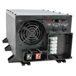
Hardwire AC Input/Output Terminals: securely connect the
Inverter/Charger to vehicle or facility electrical system input and
output.SeeACInput/OutputConnectionsectionforinstructions.
Resettable Circuit Breakers: protect your Inverter/Charger against
damageduetooverloadorchargerfailure.SeeOperationsection
for resetting instructions.
Remote Control Module Connector: allows remote monitoring
andcontrolwithanoptionalmodule(TrippLitemodelAPSRM4,
sold separately). See remote module owner’s manual for
connection instructions.
Battery Charge Conserver (Load Sense) Dial: conserves
battery power by setting the low-load level at which the Inverter/
Charger’s inverter automatically shuts off. See Configuration
section for setting instructions.
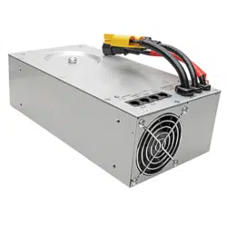
Multi-Speed Cooling Fan: quiet, efficient fan prolongs equipment
service life.
Hardwire AC Input/Output Cover Plate
Battery Temperature Sensing Connector (side mounted, not
shown): prolongs battery life by adjusting charge based on
batterytemperature.Usewithincludedcable.SeeConfiguration
section for details.
DC Power Terminal Cover Plate
1
2
3
4
5
6
7
8
9
Front View
10
11
12
13
OUTPUT/NEUTRAL
OUTPUT/HOT
GROUND
INPUT/NEUTRAL
INPUT/HOT
“FOR USE WITH COPPER WIRE ONLY”
1
24 3
5
8 910
13
6
11
12
7
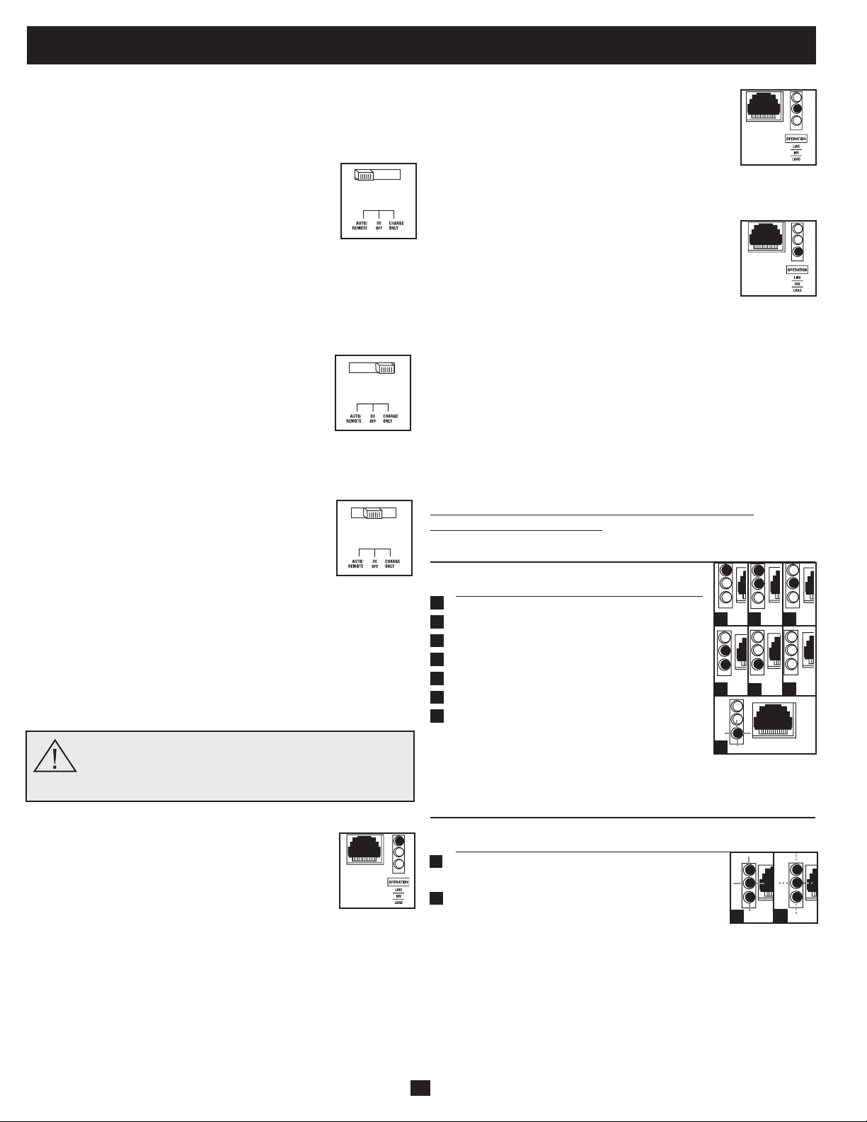
Switch Modes
After configuring, mounting and connecting your Inverter/Charger,
you are able to operate it by switching between the following
operating modes as appropriate to your situation:
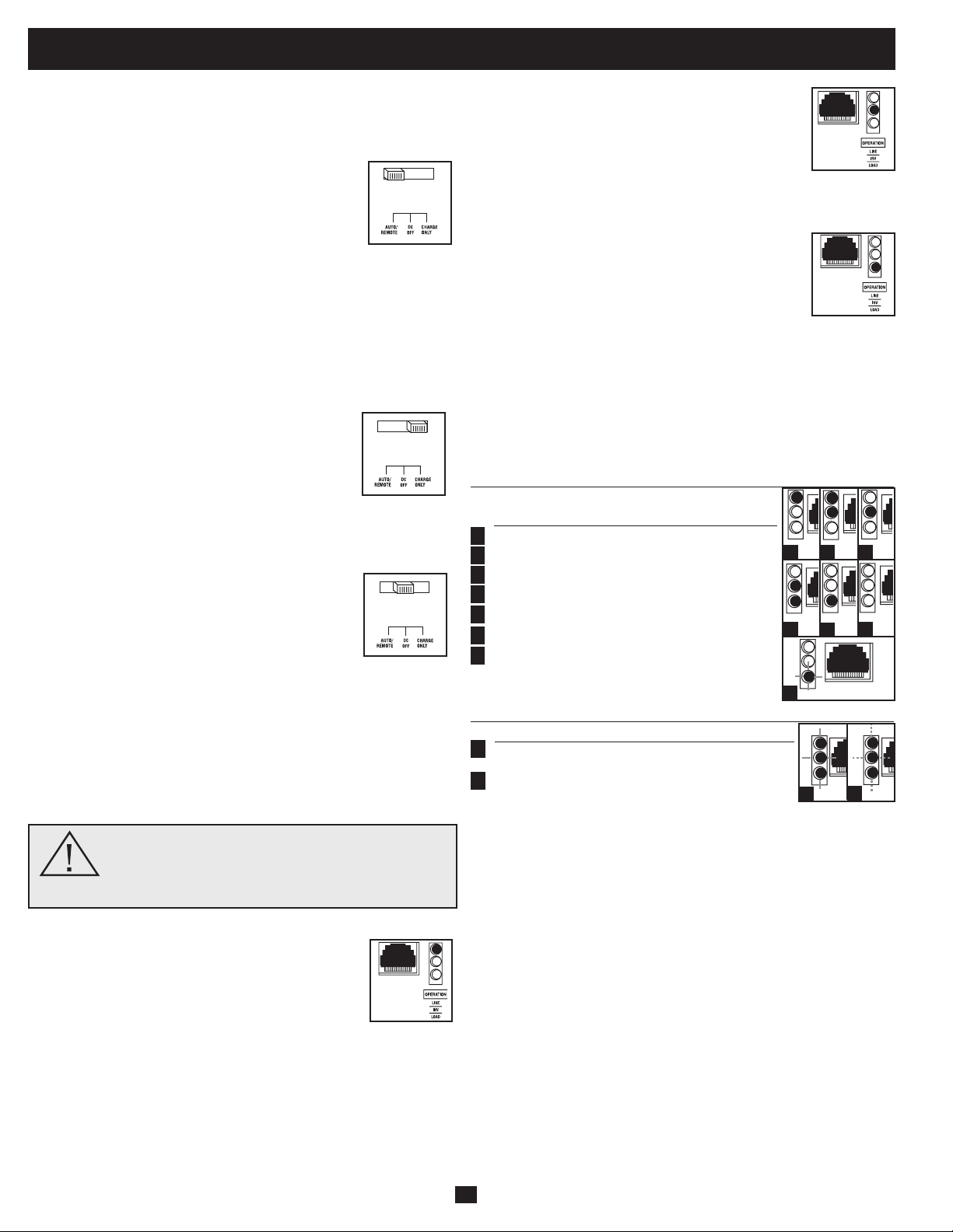
AUTO/REMOTE: Switch to this mode when you
need constant, uninterrupted AC power for connected
appliances and equipment. The Inverter/Charger will
continue to supply AC power to connected equipment
and to charge your connected batteries while utility-
or generator-supplied AC power is present. Since the
inverterisON(butinStandby)inthismode,itwillautomatically
switch to your battery system to supply AC power to connected
equipment in the absence of a utility/generator source or in over/
undervoltagesituations.“AUTO/REMOTE”alsoenablesanoptional
remotecontrolmodule(TrippLitemodelAPSRM4,soldseparately)
to function when connected to the unit.
CHARGE ONLY: Switch to this mode when you
are not using connected appliances and equipment in
order to conserve battery power by disabling the
inverter. The Inverter/Charger will continue to supply
AC power to connected equipment and charge
connected batteries while utility- or generator-supplied AC power is
present.However,sincetheinverterisOFFinthismode,itWILL
NOTsupplyACpowertoconnectedequipmentintheabsenceofa
utility/generator source or in over/under voltage situations.
DC OFF: Switch to this mode to shut down the
Inverter/Charger, preventing the inverter from
drawing power from the batteries, and preventing
utility AC from charging the batteries. The "DC
OFF"positionconnectsACOUTtoACIN,providing
failsafepass-throughpower.Usethisswitchtoautomaticallyreset
theunitifitshutsdownduetooverloadoroverheating.Firstremove
theexcessiveloadorallowtheunittosufficientlycool(applicable
to your situation). Switch to "DC OFF", then back to "AUTO/
REMOTE"or"CHARGEONLY"asdesired.Ifunitfailstoreset,
removemoreloadorallowunittocoolfurtherandtryagain.Usean
optionalremotecontrolmodule(TrippLiteModelAPSRM4,sold
separately) to reset unit after shutdown due to due to overload or
overheating.
Caution: Your Inverter/Charger has a failsafe AC
pass-through feature. The AC output will be live (if
AC input is available) even though the operating
mode switch is set to DC OFF.
Indicator Lights
Your Inverter/Charger (as well as an optional Tripp
Lite Remote Control Module, sold separately) is
equipped with a simple, intuitive, user-friendly set of
indicator lights. These easily-remembered “traffic
light” signals will allow you, shortly after first use, to
tell at a glance a wide variety of operating details.
“LINE Green LED”:Iftheoperatingmodeswitchissetto“AUTO/
REMOTE”,thislightwillILLUMINATECONTINUOUSLYwhen
your connected equipment is receiving continuous AC power
supplied from a utility/generator source.
Iftheoperatingmodeswitchissetto“CHARGEONLY”,thislight
willBLINKtoalertyouthattheunit’sinverterisOFFandwillNOT
supply AC power in the absence of a utility/generator source or in
over/under voltage situations.
“INV” (Inverting) Yellow LED: This light will
ILLUMINATE CONTINUOUSLY whenever
connected equipment is receiving battery-supplied,
inverted AC power (in the absence of a utility/
generator source or in over/under voltage situations).
This light will be off when AC power is supplying the
load.ThislightwillBLINKtoalertyouiftheloadislessthanthe
Battery Charge Conserver (Load Sense) setting.
“LOAD” Red LED: ThisredlightwillILLUMINATE
CONTINUOUSLY whenever the inverter is
functioning and the power demanded by connected
appliances and equipment exceeds 100% of load
capacity.ThelightwillBLINKtoalertyouwhenthe
inverter shuts down due to a severe overload or
overheating.Ifthishappens,turntheoperatingmodeswitch“OFF”;
remove the overload and let the unit cool. You may then turn the
operatingmodeswitchtoeither“AUTO/REMOTE”or“CHARGE
ONLY”afterithasadequatelycooled.Thislightwillbeoffwhen
AC power is supplying the load.
“BATT VOLTAGE” LEDs: If the operating mode switch is in the
"AUTO/REMOTE"or"ChargeOnly"position,theLEDsindicate
theapproximatechargelevelandvoltageofyourconnectedbattery
bank and alert you to several fault conditions. See Chart for charge
and voltage levels.
LED Function with Switch in “AUTO/REMOTE” or
“CHARGE ONLY” Position
Approximate Battery Charge Level*
LEDs Battery Capacity
Illuminated (Charging/Discharging)
Green 91%–Full
Green&Yellow 81%–90%
Yellow 61%–80%
Yellow&Red 41%–60%
Red 21%–40%
Allthreelightsoff 1%–20%
Flashingred 0%(Inverter
shutdown)**
* Charge levels listed are approximate. Actual conditions vary
depending on battery condition and load. ** Inverter shutdown protects battery against damage
due to excessive discharge.
Fault Condition
LEDs Fault
Illuminated Condition
Allthreelights Excessivedischarge
flashslowly* (Invertershutdown)
Allthreelights Overcharge
flashquickly** (Chargershutdown)
*Approximately ½ second on, ½ second off. See Troubleshooting section. Inverter shutdown
protects battery against damage due to excessive discharge.** Approximately ¼ second on, ¼
second off. Charger shutdown protects battery against damage due to overcharge. May also
indicate a battery charger fault exists. See Troubleshooting section.
4
Operation
1
2
3
4
5
6
7
1
2
1
2 3
4
5
6
7
1
2
5
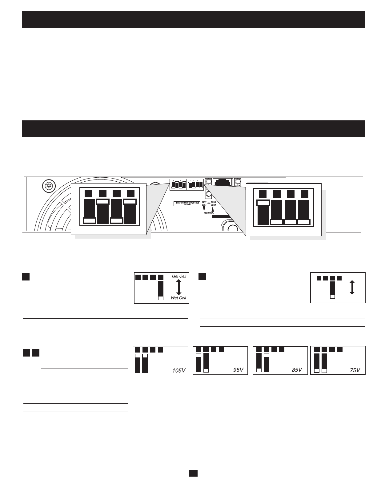
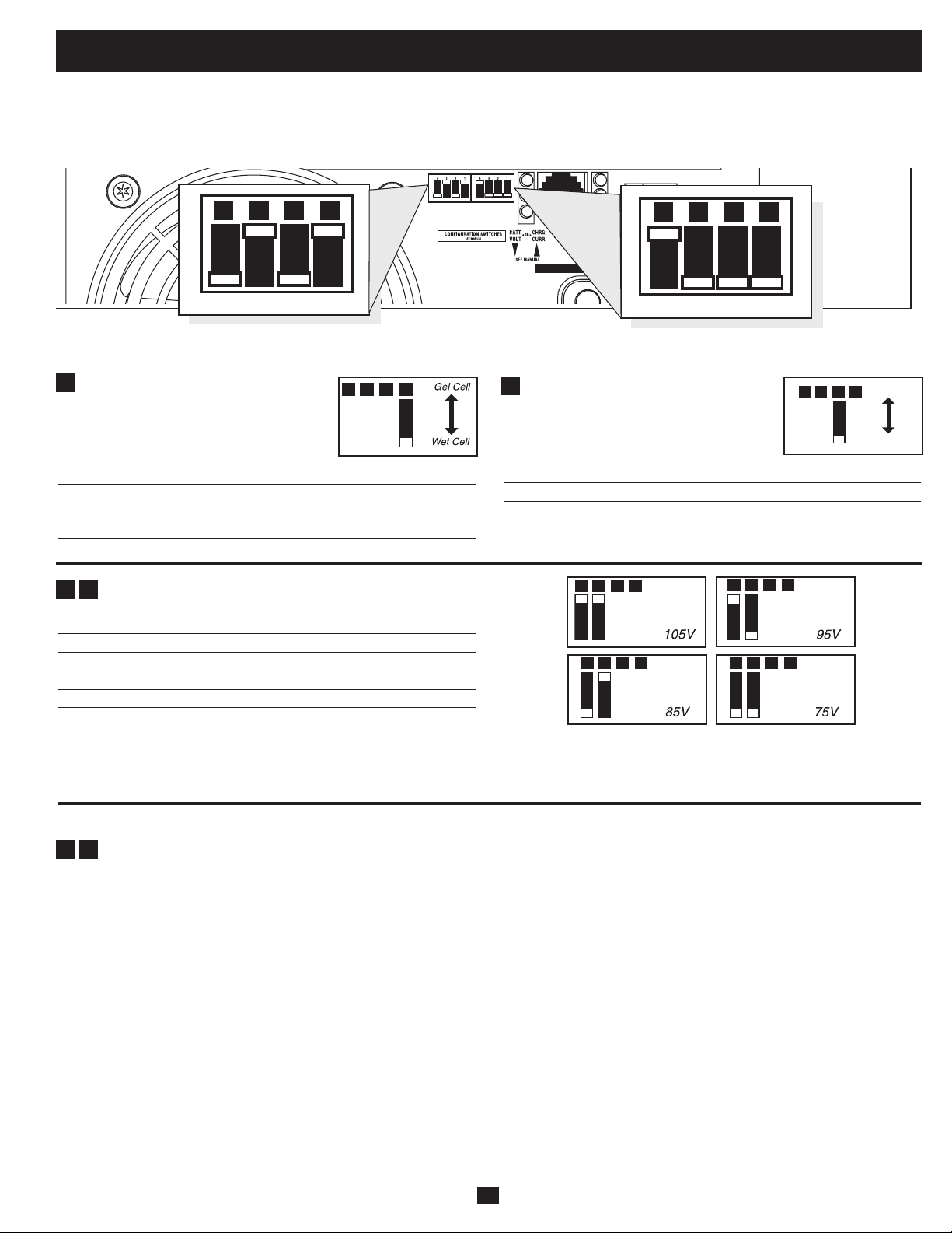
Select Battery Type—REQUIRED
CAUTION: The Battery Type DIP Switch setting must match
the type of batteries you connect, or your batteries may be
degraded or damaged over an extended period of time. See
“Battery Selection,” for more information.
Battery Type
Switch Position
GelCell(Sealed)Battery Up
Wet Cell (Vented) Battery Down (factory setting)
INPUT C/B 10A
OUTPUT C/B 12A
B4 B3 B2 B1
A4 A3 A2 A1
Group B Dip Switches
Group A Dip Switches
Group A DIP Switches
Usingasmalltool,configureyourInverter/ChargerbysettingthefourGroupADIPSwitches(locatedonthefrontpanelofyourunit;see
diagram) as follows:
A1
Operation (continued)
Resetting Your Inverter/Charger to Restore AC Power
Your Inverter/Charger may cease supplying AC power or DC charging power in order to protect itself from overload or to protect your
electrical system. To restore normal functioning:
Overload Reset:Switchoperatingmodeswitchto“DCOFF”andremovesomeoftheconnectedelectricalload(ie:turnoffsomeofthe
AC devices drawing power which may have caused the overload of the unit). Wait one minute, then switch operating mode switch back to
either“AUTO/REMOTE”or“CHARGEONLY.”
Output Circuit Breaker Reset: Alternatively, check output circuit breaker on the unit's front panel. If tripped, remove a portion of the
electrical load, wait one minute to allow components to cool, then reset the circuit breaker. See the Troubleshooting section for additional
possible reasons why AC output may be absent.
Select Low AC Input Voltage
Point for Switching to Battery—
OPTIONAL*
Switch
Voltage Position
105V #A4Up&#A3Up
95V #A4Up&#A3Down
85V #A4Down&#A3Up
75V #A4Down&#A3Down
(factory setting)
A1A2A3A4
A1A2A3A4
A1A2A3A4
A1A2A3A4
A3
A4
* Most of your connected appliances and equipment will perform adequately when your Inverter/Charger’s Low AC Voltage Input Point
(DIP Switches #3 and #4 of Group A are set to 95V. However, if the unit frequently switches to battery power due to momentary low
line voltage swings that would have little effect on equipment operation, you may wish to adjust these settings. By decreasing the Low
AC Voltage Point, you will reduce the number of times your unit switches to battery due to voltage swings.
Configuration
Set Configuration DIP Switches
Usingasmalltool,settheConfigurationDIPSwitches(locatedonthefrontpanel,seediagram)tooptimizeInverter/Chargeroperation
depending on your application.
Charger Inhibit
Function Switch Position
ChargerInhibited Up
ChargerEnabled Down(factorysetting)
A2
A1A2A3A4
A1A2A3A4
Charger
Inhibite
d
Charger
Enabled
6
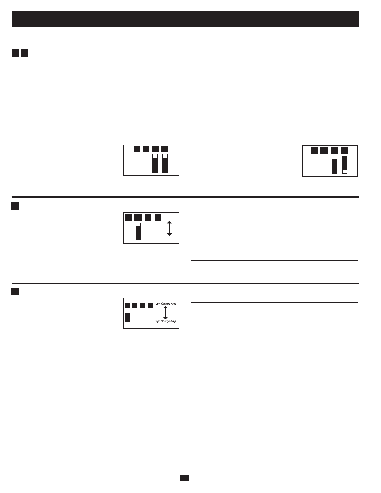
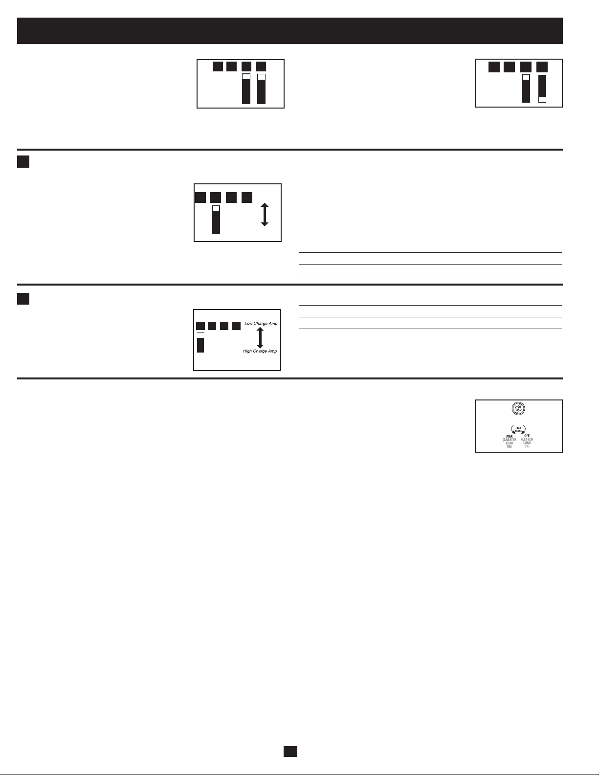
Select Battery Charger-Limiting Points—OPTIONAL
“Most Limiting” (#B2 & #B1 Up):
Charger-limiting takes effect the moment
any 120V AC load is applied; charger
output falls gradually from full output at
no120Vloadpassingthroughtonooutput
at full load.
“Less Limiting” (#B2Up&#B1Down):
Charger-limiting begins when the Inverter/
Charger’sloadreaches33%oftheInverter/
Charger’s load rating. Charger output falls
gradually from full output at 33% of the
Inverter/Charger’sloadratingtoabout40%
of full output at full load.
Configuration (continued)
B1B2B3B4
B1B2B3B4
Group B DIP Switches
Select AC Sharing—OPTIONAL
Your Inverter/Charger features a high-output battery charger that can draw a significant amount of AC power from your utility source or
generatorwhenchargingatitsmaximumrate.IfyourunitissupplyingitsfullACpowerratingtoitsconnectedheavyelectricalloadsatthe
same time as this high charging occurs, the AC input circuit breaker could trip, resulting in the complete shut off of pass-through utility
power.
To reduce the chance of tripping this breaker, all APS Inverter/Chargers may be set to automatically limit the charger output. This keeps the sum
of the unit’s AC load and charge power within the circuit breaker rating. This charger-limiting function has two settings, allowing you to
reduce the charger’s draw lower and lower, as needed, if the AC input circuit breaker keeps tripping under the normal AC loads of devices you
have connected downline from the unit. The figures show how to set your DIP Switches for charger-limiting.
B1
B2
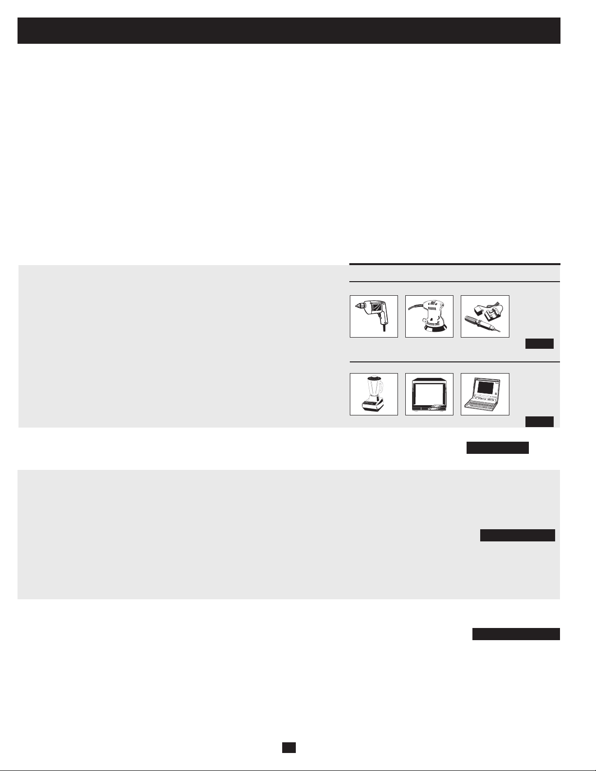
Set Battery Charging Amps—OPTIONAL
Check the nameplate for your unit’s high-
and low-charging amp options. By setting
on high charging, your batteries will charge
atmaximumspeed.Whensettingonlow
charging, you lengthen the life of your
batteries (especially smaller ones).
Battery Charger Switch Position
LowChargeAmps Up(factorysetting)
HighChargeAmps Down
CAUTION: When switching to the High Charge Amp setting, the user must ensure that the
amp hour capacity of their battery system exceeds the amperage of the High Charge Amp
setting or the batteries may be damaged or degraded.
Select Equalize Battery Charge—OPTIONAL
This DIP Switch is momentarily engaged
to begin the process of equalizing the
charge state of your battery’s cells by time-
limited overcharge of all cells. This can
extend the useful life of certain types of
batteries; consult with your battery’s
manufacturer to determine if your batteries could benefit from this
process.Thechargeequalizationprocessisautomatic;oncestarted,
it can only be stopped by removing the input power.
Setting Procedure
• Moveto“Equalize”(DOWN)positionforthreeseconds.
• Moveto“Reset”(UP)positionandleaveitthere.Thisisthe
factory default setting.
CAUTION: Do not leave DIP switch #B3 in the down position after beginning process. Battery
charge equalization should only be performed in strict accordance with the battery manufacturer’s
instructions and specifications.
Battery Charge Switch Position
Reset Up(factorysetting)
Equalize Down—momentarily
B1B2B3B4
Reset
Equaliz
e
B1B2B3B4
B4
B3
(factory setting)

7
Set Battery Charge Conserver (Load Sense) Dial—OPTIONAL
In order to save battery power, the unit’s inverter automatically shuts off in the absence of any power demand from connected
equipment or appliances (the electrical load). When the unit detects a load, it automatically turns its inverter function on.
UsersmaychoosetheminimumloadtheInverter/ChargerwilldetectbyadjustingtheBatteryChargeConserverDial(see
diagram).Usingasmalltool,turnthedialclockwisetolowertheminimumloadthatwillbedetected,causingtheinverter
to turn on for smaller loads. When the dial is turned fully clockwise, the inverter will operate even when there is no load.
Turn the dial counterclockwise to increase the minimum load that will be detected, causing the inverter to stay off until the
new minimum load is reached.
Note: the factory setting for the dial is fully clockwise. However, based on the threshold load to which you’d like the inverter to respond, you should adjust the dial counterclockwise to reduce its
sensitivity until the inverter is active only when connected equipment or appliances are actually in use.
Connect Remote Control—OPTIONAL
Modelfeaturesa8-conductortelephonestylereceptacleonthefrontpanelforusewithanoptionalremotecontrolmodule(TrippLitemodel
APSRM4,soldseparately).TheremotemoduleallowstheInverter/Chargertobemountedinacompartmentorcabinetoutofsight,while
operated conveniently from a remote location. See instructions packed with the remote control module.
Connect Battery Temperature Sensing Cable—OPTIONAL
Thebatterytemperaturesensingfunctionprolongsbatterylifebyadjustingthechargefloatvoltagelevelbasedonbatterytemperature.
Connectthesensorcable(thecable,soldseparately,hasanRJstyleconnectorononeendandablacksensorontheother)totheRJstyle
jacklocatedontheside
oftheInverter/Chargerlabeled“RemoteTemp.Sense.”Withuser-suppliedelectricalorducttape,affixthesensor
to the side of the battery below the electrolyte level. Make sure that nothing, not even tape, comes between the sensor and the side of the
battery. To guard against false readings due to ambient temperature, place the sensor between batteries, if possible, or away from sources
ofextremeheatorcold.Ifthesensorcableisnotused,theInverter/Chargerwillchargeaccordingtoitsdefault25ºCvalues.
Configuration (continued)
8
Battery Selection
540 watts ÷ 12V = 45 DC Amps
270 Amp-Hours ÷ 55 Amps
Inverter/Charger Rating = 5 Hours Recharge
Select Battery Type
Select “Deep Cycle” batteries to receive optimum performance from your Inverter/Charger. Do not use ordinary car or starting batteries or
batteries rated in Cold Cranking Amps (CCA). If the batteries you connect to the Inverter/Charger are not true Deep Cycle batteries, their
operational lifetimes may be significantly shortened. If you are using the same battery bank to power the Inverter/Charger as well as DC
loads,yourbatterybankwillneedtobeappropriatelysized(largerloadswillrequireabatterybankwithalargeramp-hourcapacity)orthe
operational lifetimes of the batteries may be significantly shortened.
BatteriesofeitherWet-Cell(vented)orGel-Cell/AbsorbedGlassMat(sealed)constructionareideal.6-volt“golfcart”,MarineDeep-Cycle
or8DDeep-Cyclebatteriesarealsoacceptable.YoumustsettheInverter/Charger’sBatteryTypeDIPSwitch(seeConfigurationsection
formoreinformation)tomatchthetypeofbatteriesyouconnectoryourbatteriesmaybedegradedordamagedoveranextendedperiodof
time.Inmanycases,thevehiclebatterymaybetheonlyoneinstalled.Auxiliarybatteriesmustbeidenticaltothevehiclebatteriesifthey
are connected to each other.
Match Battery Amp-Hour Capacity to Your Application
Select a battery or system of batteries that will provide your Inverter/Charger with proper DC voltage and an adequate amp-hour capacity
topoweryourapplication.EventhoughTrippLiteInverter/Chargersarehighly-efficientatDC-to-ACinversion,theirratedoutputcapacities
are limited by the total amp-hour capacity of connected batteries and the support of your vehicle’s alternator if the engine is kept running.
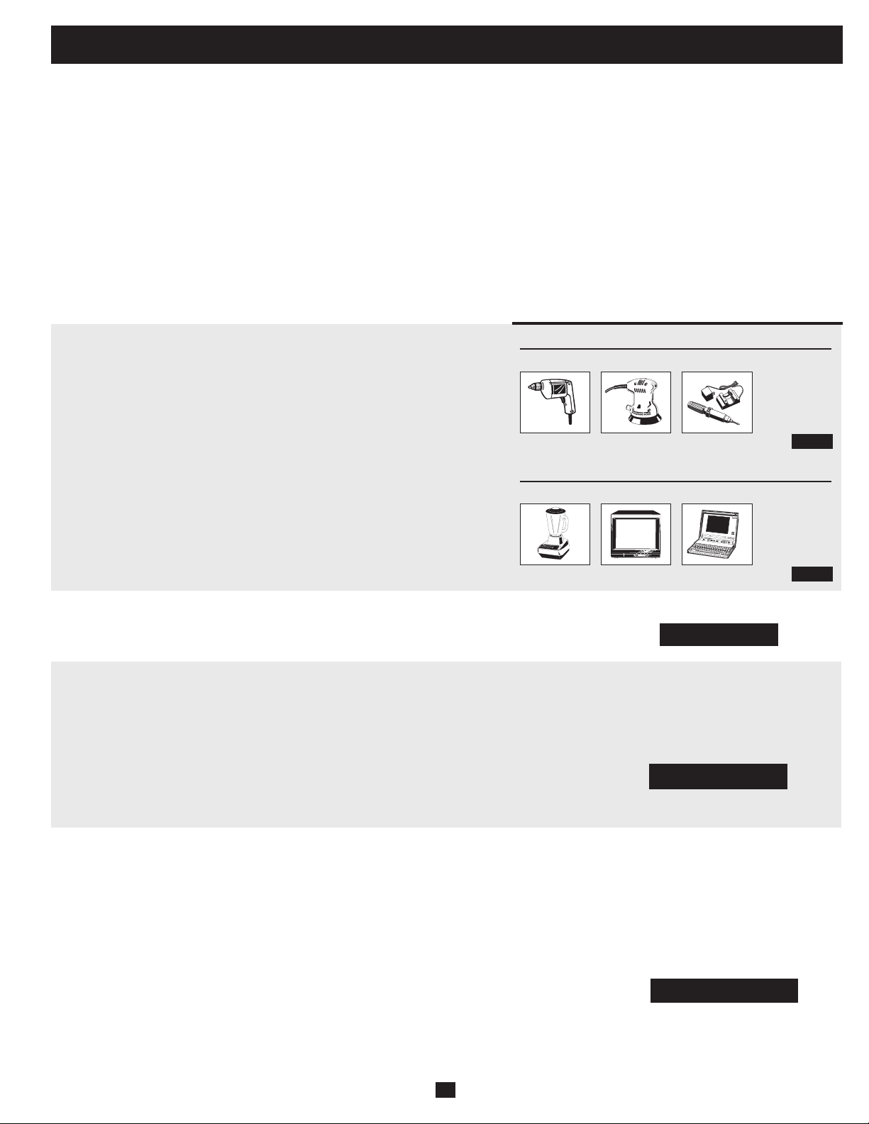
• STEP1:DetermineTotalWattageRequired
Add the wattage ratings of all equipment you will connect to your Inverter/
Charger. Wattage ratings are usually listed in equipment manuals or on
nameplates. If your equipment is rated in amps, multiply that number times AC
utilityvoltagetodeterminewatts.(Example:a¼in.drillrequires2½amps.2½
amps×120volts=300watts.)
Note: Your Inverter/Charger will operate at higher efficiencies at about 75% - 80% of nameplate rating.
• STEP2:DetermineDCBatteryAmpsRequired
Dividethetotalwattagerequired(fromstep1,above)bythebatteryvoltage(12)
to determine the DC amps required.
• STEP 3: Estimate Battery Amp-Hours Required
(for operation unsupported by the alternator)
MultiplytheDCampsrequired(fromstep2,above)bythenumberofhoursyou
estimate you will operate your equipment exclusively from battery power
before you have to recharge your batteries with utility- or generator-supplied
AC power. Compensate for inefficiency by multiplying this numberby1.2.This
will give you a rough estimate of how many amp-hours of battery power (from
one or several batteries) you should connect to your Inverter/Charger.
NOTE! Battery amp-hour ratings are usually given for a 20-hour discharge rate. Actual amp-hour capacities are less
when batteries are discharged at faster rates. For example, batteries discharged in 55 minutes provide only 50% of
their listed amp-hour ratings, while batteries discharged in 9 minutes provide as little as 30% of their amp-hour
ratings.
• STEP 4: Estimate Battery Recharge Required, Given Your Application
You must allow your batteries to recharge long enough to replace the charge
lost during inverter operation or else you will eventually run down your
batteries. To estimate the minimum amount of time you need to recharge your
batteries given your application, divide your required battery amp-hours (from
step3,above)byyourInverter/Charger’sratedchargingamps.
NOTE! For Tripp Lite Inverter/Chargers providing 1000 watts or less of continuous AC power, a full-size battery
will normally allow sufficient power for many applications before recharging is necessary. For mobile applications,
if a single battery is continuously fed by an alternator at high idle or faster, then recharging from utility or generator
power may not be necessary. For Tripp Lite Inverter/Chargers over 1000 watts used in mobile applications, Tripp Lite
recommends you use at least two batteries, if possible fed by a heavy-duty alternator anytime the vehicle is running.
Tripp Lite Inverter/Chargers will provide adequate power for ordinary usage within limited times without the
assistance of utility or generator power. However, when operating extremely heavy electrical loads at their peak
in the absence of utility power, you may wish to “assist your batteries” by running an auxiliary generator or vehicle
engine, and doing so at faster than normal idling.
Example
Tools
300W + 220W + 20W = 540W
¼" Drill
Orbital Sander
Cordless Tool Charger
Appliances
300W + 140W + 100W = 540W
Blender Color TV Laptop Computer
45 DC Amps × 5 Hrs. Runtime
× 1.2 Inefficiency Rating = 270 Amp-Hours
9
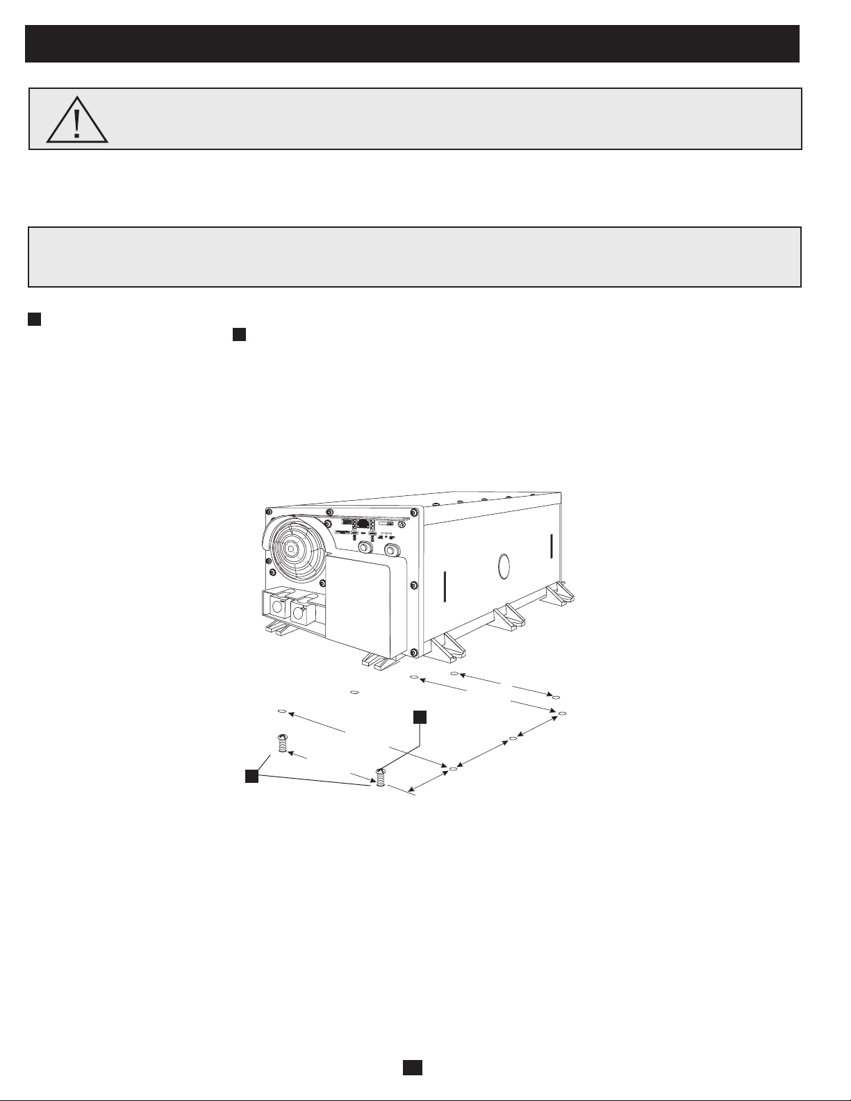
Mounting
WARNING!MountyourInverter/ChargerBEFOREDCbatteryandACpower
connection. Failure to follow these instructions may lead to personal injury and/or damage to the Inverter/
Charger and connected systems.
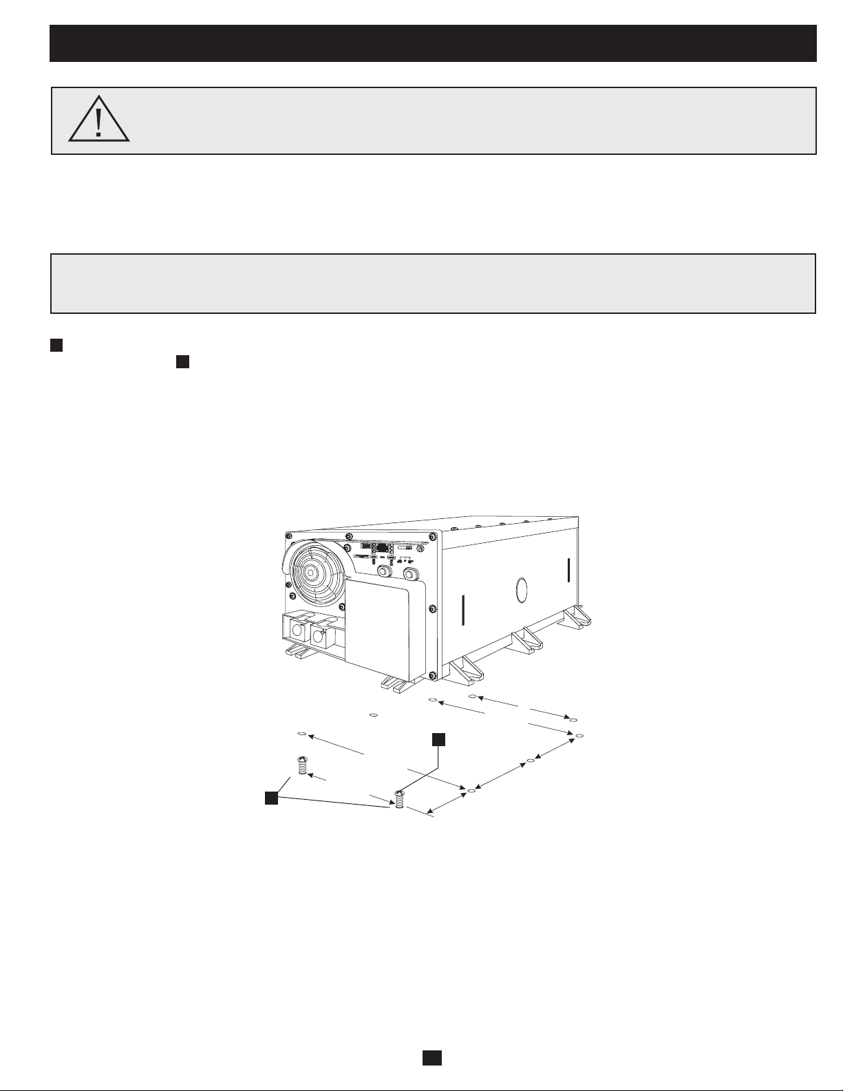
TrippLiterecommendspermanentmountingofyourInverter/Chargerasillustratedbelow.Usermustsupplymountinghardwareandis
responsible for determining if the hardware and mounting surface are suitable to support the weight of the Inverter/Charger. Contact Tripp
Lite if you require further assistance in mounting your Inverter/Charger.
Usingthemeasurementsfromthediagram,installtwouser-supplied¼"(6mm)fastenersintoarigidhorizontalsurface,leavingthe
heads slightly raised. Slide the Inverter/Charger forward over the fasteners to engage the mounting feet molded on the front of the
Inverter/Chargercabinet.Installandtightenadditionaluser-supplied¼"(6mm)fastenersintothemountingfeetmoldedontherearand
sidesoftheInverter/Chargercabinet*.Therearfeetextendbeyondtheunit’scabinettoprovideforadequateventilationspacebehindthe
coolingfan(s);theyshouldnotberemoved.
The polycarbonate cabinet and mounting feet of your Inverter/Charger are durable enough to allow for vertical mounting as well, if your
vehiclecompartmentrequiresthisconfiguration.Forverticalmounting,thecontrolpaneloftheInverter/Chargershouldfaceeitherside.
Allow 2" minimum front and rear clearance for adequate ventilation.
A
B
5.87 in.
(14.91 cm.)
1.64 in.
(4.15 cm.)
5.87 in.
(14.91 cm.)
5.57 in.
(14.16 cm.)
5.57 in.
(14.16 cm.)
9.59 in.
(24.35 cm.)
9.59 in.
(24.35 cm.)
A
B
Install your Inverter/Charger in a location where it will be shielded from outside weather conditions. Do not mount unit with its
front or rear panel facing down (at any angle). Mounting in this manner will seriously inhibit the unit's internal cooling,
eventually causing product damage not covered under warranty.
10
•ConnectDCWiring:Though your Inverter/Charger is a high-efficiency converter of electricity, its rated
outputcapacityislimitedbythelengthandgaugeofthecablingrunningfromthebatterytotheunit.Use
theshortestlengthandlargestdiametercabling(maximum2/0gauge)tofityourInverter/Charger’sDC
Input terminals (see table below). Shorter and heavier gauge cabling reduces DC voltage drop and allows
formaximumtransferofcurrentYourInverter/Chargeriscapableofdeliveringpeakwattageatupto200%
ofitsratedcontinuouswattageoutputforbriefperiodsoftime.Heaviergaugecablingshouldbeusedwhen
continuously operating heavy draw equipment under these conditions. Tighten your Inverter/Charger and
batteryterminalstoapproximately3.5Newton-metersoftorquetocreateanefficientconnectionandto
prevent excessive heating at this connection. Insufficient tightening of the terminals could void your
warranty.
Maximum Recommended DC Cable Length
Non-Vehicular or Vehicular
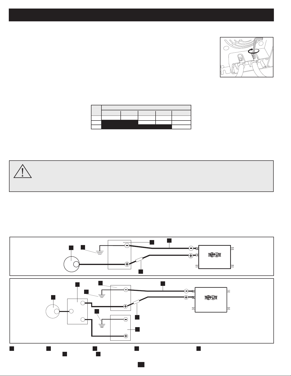
Your Inverter/Charger’s Nominal DC InputVoltage must match the voltageof your battery or batteries—12Volts in most vehicular
applications.
It is possible to connect your Inverter/Charger to the main battery within your vehicle’s electrical system. In most vehicles, the Inverter/
Chargerwillbeconnectedtooneormorededicatedauxiliary(house)batteriesthatareisolatedfromthedrivesystemtopreventpossible
draining of the main battery.
12 Volt Inverter/Charger
12 Volts
12 Volts
3
5
12 Volt Main Battery Connection
1
12 Volt Alternator
2
Vehicle Battery Ground
3
12 Volt Main Battery
4
12 Volt Auxiliary (House) Battery
5
UL-Listed Fuse & Fuse Block (mounted
within 18 inches of the battery)
6
Battery Isolator
7
Large Diameter Cabling, Maximum 2/0 Gauge to Fit Terminals
12 Volt Inverter/Charger
12 Volts
12 Volts
12 Volts
12 Volt Main and Auxiliary (House)
Battery Connection (Isolated Parallel)
1
4
1
7
6
2
2
5
7
3
2
Connect your Inverter/Charger to your batteries using the following procedures:
WARNING!•FailuretoproperlygroundyourInverter/Chargertoavehicle’schassisorearthgroundmayresultina
lethal electrical shock hazard.
•NeverattempttooperateyourInverter/Chargerbyconnectingitdirectlytooutputfromanalternatorratherthana
battery or battery bank.
•ObserveproperpolaritywithallDCconnections.
Battery Connection
DC Connectors
•ConnectFuse:NEC(NationalElectricalCode)article551requiresthatyouconnectallofyourInverter/Charger’spositiveDCTerminals
directlytoaUL-listedfuse(s)andfuseblock(s)within18inchesofthebattery.Thefuse'sratingmustequalorexceedtheminimumDC
fuse rating displayed on the Inverter/Charger's nameplate. See diagrams below for proper fuse placement.
Wire Gauge (AWG)
Output 6 4 2 0 00 (2/0)
750W 10 ft 16 ft 26 ft 42 ft 52 ft
1250W Do Not Use Do Not Use 16 ft 25 ft 31 ft
2000W Do Not Use Do Not Use Do Not Use Do Not Use 20 ft
Maximum Distance From Battery to Inverter/Charger
Warning: Do not use a wire gauge smaller than 6 AWG.
11
To avoid overloading your Inverter/Charger, match the power requirements of the equipment you plan to run at any one time (add their total
watts)withtheoutputwattagecapacityofyourInverter/Chargermodel(seeNameplate).Donotconfuse“continuous”wattagewith“peak”
wattage ratings. Most electric motors require extra power at start-up (“peak wattage”) than required to run continuously after start-up,
sometimesover100%more.Somemotors,suchasinrefrigeratorsandpumps, start and stop intermittently according to demand, requiring
“peak wattage” at multiple, unpredictable times during operation.
OverPower™ Feature
TrippLiteInverter/Chargersdeliverupto150%oftheirnameplate-ratedwattagefor1-60minutesunderidealbatteryandtemperature
conditions,providingamplereservepowertosupporttoolsandequipment.*
* For best results, utilize OverPower for as short a duration as possible, ensure that battery bank and cabling are able to provide full nominal DC voltage under load, and allow the inverter/charger
to cool completely before and after OverPower utilization.
DoubleBoost™ Feature
TrippLiteInverter/Chargersdeliveruptotwicetheirnameplate-ratedwattageforupto10seconds,providingtheextrapowerneededto
cold-startheavy-dutytoolsandequipment.*
* Actual duration depends on model, battery age, battery charge level and ambient temperature.
AC Input/Output Connection
Service
BeforereturningyourInverter/Chargerforservice,followthesesteps:1.)Reviewtheinstallationandoperationinstructionstoensurethat
theserviceproblemdoesnotoriginatefromamisreadingoftheinstructions.Also,checkthatthecircuitbreaker(s)arenottripped.*2.)If
the problem continues, do not contact orreturn the Inverter/Chargerto the dealer. Instead, callTripp Lite at773.869.1233.A service
technician will ask for the Inverter/Charger’s model number, serial number and purchase date and will attempt to correct the problem over
thephone.3.)Iftheproblemrequiresservice,thetechnicianwillissueyouaReturnedMaterialAuthorization(RMA)number,whichis
requiredforservice.SecurelypacktheInverter/Chargertoavoiddamageduringshipping.DonotuseStyrofoambeadsforpackaging.**
Any damages (direct, indirect, special, incidental or consequential) to the Inverter/Charger incurred during shipment to Tripp Lite or an
authorizedTrippLiteservicecenterisnotcoveredunderwarranty.Inverter/ChargersshippedtoTrippLiteoranauthorizedTrippLite
servicecentermusthavetransportationchargesprepaid.MarktheRMAnumberontheoutsideofthepackage.IftheInverter/Chargeris
withinthewarrantyperiod,encloseacopyofyoursalesreceipt.ReturntheInverter/Chargerforserviceusinganinsuredcarriertothe
address given to you by the Tripp Lite service technician.
* This is a common cause of service inquiries which can be easily remedied by following the resetting instructions in this manual. ** If you require packaging, the technician can arrange to send
you proper packaging.
Your Inverter/Charger requires no maintenance and contains no user-serviceable or replaceable parts, but should be kept dry at all times.
Periodically check, clean and tighten all cable connections, as necessary, both at the unit and at the battery.
Maintenance
Ground*
• Connecttheincomingandoutgoinggroundwirestotheground(green)terminal.
AC Input
• Connect the incoming hot wire to the input hot (brown) terminal .
• Connecttheincomingneutralwiretotheinputneutral(blue)terminal.
AC Output
• Connect the outgoing hot wire to the output hot (black) terminal .
• Connecttheoutgoingneutralwiretotheoutputneutral(white)terminal.
• Replacecoverplateandtightenscrews.
* If the incoming conduit only contains two wires (hot and neutral), the incoming conduit must be bonded to the main ground lug on the
unit. In any case, the incoming conduit must be bonded to earth or vehicle ground, and the incoming conduit must be bonded to the
outgoing conduit.
1
2
3
4
5
Warning! Consult a qualified electrician and follow all applicable electrical codes and requirements for hardwire
connection. Disconnect both DC input and AC utility supply before attempting hardwiring. Use wire type THHN or
equivalent with minimum temperature rating of 90°C.
Hardwire Connection
Removethescrewsandcoverplateoverthehardwireterminal box.Removetheknockoutcoversclosesttothedesiredelectricalsourceand
toyourequipment.Attach½"diameterconduits(user-supplied)totheknockoutsandthreadwiresthrough.Connecttheconduitstoeach
other with the ground bond connection supplied.
OUTPUT/NEUTRAL
OUTPUT/HOT
INPUT/NEUTRAL
INPUT/HOT
GROUND
“FOR USE WITH COPPER WIRE ONLY”
5
4
1
3
2
12
Troubleshooting
SYMPTOM PROBLEMS CORRECTIONS
No AC Output Unit is not properly connected to utility power Connect unit to utility power.
(All Indicator Lights are OFF) Operating Mode Switch is set to “DC OFF” and AC input Set Operating Mode Switch to “AUTO/REMOTE” or “CHARGE ONLY”.
is present.
This is normal when the Operating Mode Switch is set to No correction is required. AC output will return when AC input
“CHARGE ONLY” and AC input is absent. returns. Set Operating Mode Switch to “AUTO/REMOTE” if you
require AC output.
Output circuit breaker is tripped. Reset circuit breaker.
Unit has shut down due to battery overcharge (preventing Disconnect any auxiliary chargers. Reset by moving Operating Mode
battery damage). The problem may be with connected Switch to “DC OFF”. Wait 1 minute and switch to “AUTO/REMOTE” or
auxiliary chargers, if any, or with the unit’s charger. “CHARGE ONLY.” If unit remains in shutdown mode after several
attempts to reset, contact Tripp Lite Customer Service for assistance.
Unit has shut down due to excessive battery discharge. Use an auxiliary charger* to raise battery voltage. Check external
battery connections and fuse. Unit automatically resets when
condition is cleared.
Unit has shut down due to overload. Reduce load. Reset by moving Operating Mode Switch to “DC OFF”.
Wait 1 minute. Switch to “AUTO/REMOTE” or “CHARGE ONLY”.
Battery Not Recharging Connected batteries are dead. Check and replace old batteries.
(AC Input Present) Battery fuse* is blown. Check and replace fuse.*
Battery cabling* is loose. Check and tighten or replace cabling.*
Unit has shut down due to battery overcharge (preventing Disconnect any auxiliary chargers. Reset by moving Operating Mode
battery damage). The problem may be with connected Switch to “DC OFF”. Wait 1 minute and switch to “AUTO/REMOTE” or
auxiliary chargers, if any, or with the unit’s charger. or “CHARGE ONLY.” If unit remains in shutdown mode after several
attempts to reset, contact Tripp Lite Customer Service for assistance.
Charger circuit breaker is tripped. Reset circuit breaker.
All Three “BATT VOLT/CHRG CURR” Battery is excessively discharged. Unit will shut down to Use an auxiliary charger* to raise battery voltage. Check external
LEDs are slowly flashing (½ second prevent battery damage. battery connections and fuse. Unit automatically resets when
flashes) with Operating Mode Switch in condition is cleared.
the “AUTO/REMOTE” position.
All Three “BATT VOLT/CHRG CURR” Battery is overcharged. Unit will shut down to prevent Disconnect any auxiliary chargers. Reset by moving Operating Mode
LEDs are rapidly flashing (¼ second battery damage. The problem may be with connected auxiliary Switch to “DC OFF”. Wait 1 minute and switch to “AUTO/REMOTE.”
flashes) with Operating Mode Switch in chargers, if any, or with the unit’s charger. If unit remains in shutdown mode after several attempts to reset,
the “AUTO/REMOTE” position. contact Tripp Lite Customer Service for assistance.
Red “LOW” Battery Indicator Light is Battery voltage is low. Unit has shut down If AC power (utility- or generator-supplied) is present, the unit will
flashing with Operating Mode Switch in the to protect battery from damage. automatically reset itself and start recharging connected batteries.
”AUTO/REMOTE” position. However, if an external charger is used to recharge the batteries,
you will need to manually reset the unit by moving the Operating
Mode Switch to “DC OFF” for two seconds then returning it to
“AUTO/REMOTE”.
False reading due to undersized or Use sufficient size DC cable sufficiently connected to
insufficiently connected DC cabling. Inverter/Charger.
Red “LOAD” Operation Inverter is overloaded. Unit will automatically shut down Reduce load. Reset by moving Operating Mode Switch to “DC OFF”.
Indicator Light flashing after 5 seconds. Wait 1 minute. Switch to “AUTO/REMOTE” or “CHARGE ONLY”.
* User-supplied.
TrytheseremediesforcommonInverter/Chargerproblemsbeforecallingforassistance.CallTrippLiteCustomerServiceat773.869.1234
before returning your unit for service.
Limited Warranty
Tripp Lite warrants its Inverter/Chargers to be free from defects in materials and workmanship for a period of one year (except for outside of U.S.A., Canada and Mexico-120 days) from the date of retail purchase by
end user
Tripp Lite’s obligation under this warranty is limited to repairing or replacing (at its sole option) any such defective products. To obtain service under this warranty you must obtain a Returned Material Authorization
(RMA) number from Tripp Lite or an authorized Tripp Lite service center. Products must be returned to Tripp Lite or an authorized Tripp Lite service center with transportation charges prepaid and must be
accompanied by a brief description of the problem encountered and proof of date and place of purchase. This warranty does not apply to equipment which has been damaged by accident, negligence or
misapplication or has been altered or modified in any way, including opening of the unit’s casing for any reason. This warranty applies only to the original purchaser who must have properly registered the product
within 10 days of retail purchase.
EXCEPT AS PROVIDED HEREIN, TRIPP LITE MAKES NO WARRANTIES, EXPRESS OR IMPLIED, INCLUDING WARRANTIES OF MERCHANTABILITY AND FITNESS FOR A PARTICULAR PURPOSE.
Some states do not permit limitation or exclusion of implied warranties; therefore, the aforesaid limitation(s) or exclusion(s) may not apply to the purchaser.
EXCEPT AS PROVIDED ABOVE, IN NO EVENT WILL TRIPP LITE BE LIABLE FOR DIRECT, INDIRECT, SPECIAL, INCIDENTAL OR CONSEQUENTIAL DAMAGES ARISING OUT OF THE USE OF THIS
PRODUCT, EVEN IF ADVISED OF THE POSSIBILITY OF SUCH DAMAGE. Specifically, Tripp Lite is not liable for any costs, such as lost profits or revenue, loss of equipment, loss of use of equipment, loss of
software, loss of data, costs of substitutes, claims by third parties, or otherwise
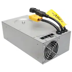
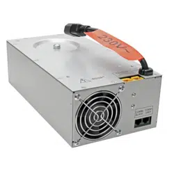
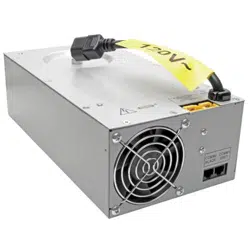
Note on Labeling Two symbols are used on the labels.
V~: AC Voltage V : DC Voltage
WARRANTY REGISTRATION
Visit www.tripplite.com/warranty to register the warranty of your new Tripp Lite product. You'll be automatically
entered into a drawing for a chance to win a FREE Tripp Lite product!*
* No purchase necessary. Void where prohibited. Some restrictions apply. See website for details.
Regulatory Compliance Identification Numbers
For the purpose of regulatory compliance certifications and identification, your Tripp Lite product has been
assigned a unique series number. The series number can be found on the product nameplate label, along with
all required approval markings and information. When requesting compliance information for this product,
always refer to the series number. The series number should not be confused with the marking name or model
number of the product.
Tripp Lite has a policy of continuous improvement. Specifications are subject to change without notice.
Made in China.
200904174 93-2748-EN
1111 W. 35th Street, Chicago, IL 60609 USA
Customer Support: 773.869.1234 • www.tripplite.com
13
Manual del Propietario
Confiable energía de respaldo de emergencia
¡Felicitaciones!Haadquiridoelinversor/cargadormásavanzadoyconmásfunciones,diseñadocomounafuentealternativadeenergía
durantefallasdelsuministrodeenergíadelared.Losinversores/cargadoresTrippLiteAPSmantienensusequiposconstantementeen
operaciónyproductivosdurantecualquierproblemadeenergíadelared(fallasdelservicioeléctrico,bajasdevoltajeyvoltajesaltos)
convirtiendolaenergíadecorrientecontinuadebateríassuministradasporelusuario,enenergíadecorrientealterna.Cuandohayenergíade
lared,losinversores/cargadoresAPSpasanautomáticamentelaenergíaasusequipos,yrecargansimultáneamenteelbancodebaterías
conectado. La supresión de sobretensiones integrada proporciona un nivel adicional de protección al equipo. Los inversores/cargadores APS
sonlaalternativasilenciosaalosgeneradoresdegasolinaduranteaplicacionesderespaldodeemergencia.Obtieneelectricidaddecorriente
alterna en cualquier lugar y en cualquier momento en que la necesite-¡sin humo, combustible ni ruido!
Mejor para su equipo NivelesdeprotecciónPremium
•ProteccióncontrasobretensionesintegradaIsobar
®
•Protecciónautomáticadesobrecarga
Salida ideal para cualquier carga (incluyendo computadoras)
•Salidacontroladaporfrecuencia
•Rápidaconmutacióndecarga
•Repartodecargabalanceada
Mejor para sus baterías Recargadebateríasmásrápida
•Cargadordebateríasde3etapasdealtacapacidad(ajustable)
Proteccióncríticadebatería
•Conservadordecargadebatería(Deteccióndecarga)
•Deteccióndetemperaturadebatería
•InversióndeCCaCAdealtaeficiencia
Mejor para usted Operaciónsimple,sinmantenimiento
•Lucesyconmutadoresmultifunción
•Fabricaciónresistentealahumedad*
Instrucciones de seguridad importantes 14
Identificación de funciones 15
Operación 16
Configuración 17-18
Selección de baterías 19
Montaje 20
Conexión de la batería 21
Conexión de entrada/salida de
corriente alterna/Servicio 22
Mantenimiento/Solución de problemas 23
Garantía limitada
24
PowerVerter
®
Serie APS Inversor/cargador de
corriente continua a corriente alterna
Entrada Salida
Inversión: 12 VCC 120V, 60 Hz. VAC
Carga: 120V, 60 Hz. AC 12 VCC
1111 W. 35th Street, Chicago, IL 60609 USA
Soporte al cliente: 773.869.1234
www.tripplite.com
* Los inversores/cargadores son resistentes a la humedad, pero no son impermeables.
Copyright © 2009. PowerVerter
®
y Isobar
®
son marcas registradas de Tripp Lite. Todos los derechos reservados
Contenido
14
Instrucciones de seguridad importantes
¡GUARDE ESTAS INSTRUCCIONES!
Estemanualcontieneinstruccionesyadvertenciasimportantesquedebenseguirsedurantelainstalación,operaciónyalmacenamientode
este producto.
Advertencias de ubicación
• Instale su inversor/cargador (ya sea para una aplicación móvil o estacionaria) en un lugar o compartimiento que minimice la
exposiciónalcalor,alpolvo,alaluzsolardirectayalahumedad.
• Aunquesuinversor/cargadoresresistentealahumedad,NOesimpermeable.Llenarlaunidadconaguacausaráuncortocircuitoy
podríacausarlesionespersonalesporchoqueeléctrico.Nuncasumerjalaunidad,yevitecualquieráreadondepuedaacumularseagua.
Elmontajedeberealizarseenlaubicaciónmássecadisponible.
• Dejeunaluzmínimade5cm(2")enlapartefrontalyposteriordelinversor/cargadorparaunaadecuadaventilación.Amayorcargael
equipoconectado,launidadgenerarámáscalor.
• Noinstaleelinversor/cargadordirectamentecercademediosdealmacenamientomagnético,yaquepuedeprovocardañoalosdatos.
• Noinstalecercadematerialesinflamables,combustibleoproductosquímicos.
• No monte esta unidad con el panel frontal o con el panel trasero hacia abajo (Bajo ningún ángulo o inclinación). Si lo monta de
esta manera, inhibirá seriamente el sistema de enfriamiento interno de la unidad; lo que finalmente causará daños al producto
que no están cubiertos por la garantía.
Advertencias de conexión de batería
• Elinversor/cargadornofuncionará(conenergíadelaredosinella)hastaqueseconectenlasbaterías.
• Lossistemasdebateríasmúltiplesdebenestarformadosdebateríasconunvoltaje,unaantigüedad,unacapacidadenamperioshoray
untipoidénticos.
• Debidoaquepuedeacumularsegashidrógenoexplosivocercadelasbateríassinoestánbienventiladas,nodebeinstalarbaterías(ya
seaparaunaaplicaciónmóviloestacionaria)enuncompartimientosincirculacióndeaire.Enformaideal,cualquiercompartimiento
tendríaciertaventilaciónalexterior.
• Puedenproducirsechispasdurantelaconexiónfinaldelabatería.Siempreobservelacorrectapolaridadalconectarlasbaterías.
• Nopermitaqueningúnobjetoentreencontactoconlosdosterminalesdeentradadecorrientecontinua.Nopongaencortocircuitoni
enpuenteestosterminales.Podríanproducirseseriaslesionespersonalesodañosalapropiedad.
Advertencias sobre la conexión de equipos
• Elusodeesteequipoenaplicacionesdesoportedevidaendondelafalladeesteequipopuedarazonablementehacersuponer
que causará fallas en el equipo de soporte de vida o afecte significativamente su seguridad o efectividad, no está recomendado.
No use este equipo en la presencia de una mezcla anestésica inflamable con aire, oxigeno u óxido nitroso.
• Conectesuinversor/cargadorsóloaunasalidadecorrientealternaoaunafuentecableadaadecuadamentepuestaatierra.Noconectela
unidadasimisma;estodañaráeldispositivoyanularásugarantía.
• Puedeexperimentarunfuncionamientoirregularsiconectaunsupresordesobretensiones,unacondicionadordelíneaounsistema
UPSalasalidadelinversor/cargador.
Advertencias de operación
• Suinversor/cargadornorequiereunmantenimientoderutina.Noabraeldispositivoporningunarazón.Nohaypartesquerequieran
man tenimiento por parte del usuario en su interior.
• Existenvoltajespotencialmenteletalesdentrodelinversor/cargador,entantolaalimentacióndebateríasy/olaentradadecorriente
alternaesténconectadas.Enconsecuencia,durantecualquiertrabajodemantenimiento,debendesconectarselaalimentaciónde
bateríasylaentradadecorrientealterna.
• Noconecteodesconectelasbateríasmientraselinversor/cargadorestáoperandoenmododeinversiónodecarga.Elconmutador
debeestarenlaposiciónDCOFF.Puedeproducirseunarcopeligroso.
Precaución: Su Inversor/Cargador tiene una función de paso directo de corriente CA a prueba de fallas. La salida
CA estará viva (Si hay entrada CA disponible) aunque el Interruptor de Modo de Operación este colocado en DC
OFF [DC Apagada].
15
Identificación de funciones
IdentificalasfuncionesPremiumensumodeloespecíficoyubicarápidamentelasinstruccionesparaoptimizarsuutilización.
Conmutadores DIP de configuración:optimizanlaoperación
de su inversor/cargador en función de su aplicación. Vea la
seccióndeConfiguraciónparainstruccionesdeajuste.
Conmutador de modo de operación: controla la operación del
inversor/cargador. El ajuste"AUTO/REMOTE"aseguraquesu
equiporecibeunaenergíaconstanteeininterrumpidadecorriente
alterna. También permite monitorear y controlar el inversor/
cargador en forma remota con un módulo opcional remoto (Tripp
Lite modelo APSRM4, vendido por separado o incluido con
modelosexclusivos)Elajuste"CHARGEONLY"permiteasus
bateríasregresaracargacompletamásrápidamentemedianteel
apagado del inversor,lo que detiene la descargade la batería.
ColocandoelInterruptordeMododeOperaciónenlaposición
"DC OFF" [CD Apagada] (al centro) desactivará la unidad y
conectará"ACOUT"[CASale]a"ACIN."[CAEntra]Veala
secciónOperaciónporinstrucciones.
Luces indicadoras de operación:intuitivaslucestipo"semáforo"
muestransielinversor/cargadorestáoperandodesdeunalíneade
corrientealternaoconenergíadecorrientecontinuadebaterías.
Tambiénleadviertesilacargadelequipoconectadoesdemasiado
alta.VealaseccióndeOperaciónparainstrucciones.
Luces indicadoras de batería: Estas tres luces iluminaránen
variassucesionespara mostrar el nivelaproximado de batería.
VealaseccióndeOperaciónparainstruccionessobrelalectura
de las luces indicadoras.
Terminales de potencia de corriente continua: se conectan a
losterminalesdesubatería.VeaseccióndeConexióndebatería
parainstruccionesdeconexión.
Regleta cableada de terminales de entrada/salida de corriente
alterna: conecta firmemente el inversor/cargador al sistema
eléctricodelaredodelvehículo.VealaseccióndeOperación
parainstruccionesdeconexión.
Interruptores automáticos restaurables: protegen su inversor/
cargadorcontradañosporsobrecargaofaltadelcargador.Veala
seccióndeOperaciónparainstruccionesdereajuste.
Conector del módulo de control remoto: permite el monitoreo
y control en forma remota con un módulo opcional (Tripp Lite
modelo APSRM4, vendido por separado) Vea el Manual del
propietario del módulo remoto para obtener instrucciones de
conexión.
Control del conservador de carga de batería (Detección de
carga): conservalaenergíadebateríaajustandoelniveldecarga
baja en el que el inversor/cargador se apaga automáticamente.
VeaseccióndeConfiguraciónparainstruccionesdeajuste.
Ventilador de enfriamiento controlado por termostato:
ventilador silencioso y eficiente que regula la temperatura interna
y prolonga la cida de servicio del equipo
Placa de cubierta de entrada/salida de CA cableada
Conector de detección de temperatura de batería (montaje
lateral, no mostrado): prolongalavidadelabateríaajustando
lacargaenfuncióndelatemperaturadelabatería.Usoconcable
(incluidoenmodelosexclusivos)VealaseccióndeConfiguración
para detalles.
Placa de cubierta de terminales de energía CC
1
2
3
4
5
6
7
8
9
10
11
12
13
OUTPUT/NEUTRAL
OUTPUT/HOT
GROUND
INPUT/NEUTRAL
INPUT/HOT
“FOR USE WITH COPPER WIRE ONLY”
1
24 3
5
8 910
13
6
11
12
7
Vista frontal
16
Operación
Modos de conmutación
Después de la configuración, el montaje y la conexión de su inversor/
cargador, puede operarlo cambiando a los siguientes modos de operación,
segúncorresponda:
AUTO/REMOTE: Cambie a este modo cuando necesite
energíadecorrientealternaconstanteeininterrumpidapara
los aparatos y equipos conectados. El inversor/cargador
seguirá suministrando energía de corriente alterna al
equipo conectado y para cargar sus baterías conectadas
mientrasexistaenergíadecorrientealternadelared-ode
un generador. Ya que el inversor está en posición ON
(aunqueenStandbyoReserva)enestemodo,cambiaráautomáticamentea
susistemadebateríaparasuministrarenergíadecorrientealternaalequipo
conectado en ausencia de alimentación de la red o de un generador, o en
casosdesobrevoltajeobajovoltaje."AUTO/REMOTE"tambiénpermiteun
módulodecontrolremotoopcional(TrippLitemodeloAPSRM4,vendido
por separado o incluido con modelos exclusivos) para operar al estar
conectado a la unidad. Este ajuste también permite la operación del
Conmutador de modo de operación redundante montado en el panel
superiordelosmodelosexclusivos
CHARGE ONLY:Cambieaestemodocuandonoesté
usando aparatos ni equipos conectados, a fin de conservar
energíadebateríamedianteladesactivacióndelinversor.
El inversor/cargador seguirá suministrando energía de
corriente alterna al equipo conectado y cargando las
baterías conectadas mientras exista energía de corriente
alternadelared-odeungenerador.Sinembargo,yaqueelinversorestá
OFF(apagado)enestemodo,NOsuministraráenergíadecorrientealterna
al equipo conectado en ausencia de alimentación de la red o de un generador,
oencasosdesobrevoltajeobajovoltaje.
DC OFF: [CD Apagada]: Cambie a este modo para
apagar el Inversor/Cargador, evitando que el inversor tome
energíadelasbateríasyevitandoquelacorrienteCAdel
servicio público cargue las baterías. La posición "DC
OFF"[CDApagada]conectaACOUT[CASale]aACIN
[CAEntra],ofreciendoelpasodirectodelacorrientea
prueba de fallas. Use este interruptor para restablecer la unidad
automáticamentesiseapagaporsobrecargaosobrecalentamiento.Primero
remueva la carga excesiva o permita a la unidad enfriarse lo suficiente,
(comoseaaplicableasusituación).Cambiea"DCOFF"[CDApagada]y
luegoregresea"AUTO/REMOTE"[Auto/Remoto]o"CHARGE ONLY"
[SoloCarga]comodesee.Silaunidadnoserestablece,quitemáscargao
permita que la unidad se enfríe aun más e inténtelo de nuevo. Use un
módulodecontrolremotoopcional(TrippLiteModeloAPSRM4,vendido
por separado) para restaura la unidad después que se haya apagado por
sobrecarga o sobrecalentamiento.
Precaución: Su Inversor/Cargador tiene una función de
paso directo de corriente CA a prueba de fallas. La
salida CA estará viva (Si hay entrada CA disponible)
aunque el Interruptor de Modo de Operación este
colocado en DC OFF [DC Apagada].
Luces indicadoras
Su inversor/cargador (así como su Módulo opcional de
control remoto Tripp Lite, vendido por separado o incluido
con modelos exclusivos) está equipado con un sencillo,
intuitivo,yfácildeutilizar,conjuntodelucesindicadoras.
Estasluces"tiposemáforo"fácilesderecordar,lepermitirán
en poco tiempo después del primer uso, saber de una
miradalacondicióndecargadesusbaterías,asícomociertosdetallesde
operación y condiciones de falla.
Indicador LINE verde:Sielconmutadordemododeoperaciónsefijaen
"AUTO/REMOTE,"estaluzseILUMINARÁCONTINUAMENTEcuando
suequipoconectadoestérecibiendoenergíadecorrientealternaenforma
constante, suministrada desde la red o de un generador.
Sielconmutadordemododeoperaciónsefijaen"CHARGEONLY,"(sólo
carga)estaluzDESTELLAparaalertarlequeelinversordelaunidadestá
OFF y que NO suministrará energía de corriente alterna en ausencia de
alimentacióndelaredodeungenerador,oencasosdesobrevoltajeobajo
voltaje.
Indicador INV (Inversión) amarillo: Esta luz se
ILUMINARÁCONTINUAMENTEsiemprequeelequipo
conectado esté recibiendo energía de corriente alterna
convertidadesdebaterías(enausenciadealimentaciónde
laredodeungenerador,oencasosdesobrevoltajeobajo
voltaje)Estaluzseapagacuandolacargaestáalimentada
conenergíadecorrientealterna.EstaluzDESTELLARÁ
paraalertarlesilacargaesmenorqueelajusteConservadordecargade
batería(Deteccióndecarga).
Indicador rojo LOAD (carga): Esta luz roja se
ILUMINARÁCONTINUAMENTEsiemprequeelinversor
estéfuncionandoyquelaenergíarequeridaporlosaparatos
yequiposconectadosexcedael100%delacapacidadde
carga. La luz DESTELLARÁ para alertarle cuando el
inversor se apague debido a una severa sobrecarga o por
sobrecalentamiento. Si esto sucede, cambie el conmutador
almododeoperación"OFF";retirelasobrecargaydejequelaunidadse
enfríe. Después de que la unidad se haya enfriado, puede cambiar el
conmutador de modo de operación a "AUTO/REMOTE" o "CHARGE
ONLY".Estaluzseapagacuandolacargaestáalimentadaconenergíade
corriente alterna.
Luces indicadoras de batería: Estas tres luces se iluminarán en varias
secuencias para mostrar el nivel aproximado de carga de su banco de
bateríasconectadoyparaalertarlededoscondicionesdefalla:
Nivel aproximado de carga de batería*
Indicador Capacidad de batería
iluminado (Carga/Descarga)
Verde 91%-completa
Verdeyamarillo 81%-90%
Amarillo 61%-80%
Amarilloyrojo 41%-60%
Rojo 21%-40%
Lastreslucesapagadas 1%-20%
Rojodestellando 0%(Inversorapagado)
* Los niveles de carga indicados son aproximados. Las condiciones
reales varían en función de la condición y carga de la batería.
Condición de falla
Indicador iluminado Condición de falla
Las tres luces destellan Descargaexcesiva
lentamente* (Inversor apagado)
Las tres luces destellan Sobrecarga
rápidamente** (Cargador apagado)
*Aproximadamente ½ segundo encendido, ½ segundo apagado. Vea la sección Solución de
problemas. ** Aproximadamente ¼ segundo encendido, ¼ segundo apagado. También puede
indicar una falla del cargador de batería. Vea la sección Solución de problemas.
1
2
3
4
5
6
7
1
2
1
2 3
4
5
6
7
1
2
Restableciendo su inversor/cargador para
restablecer la energía de corriente alterna
Suinversor/cargadorpuededejardesuministrarenergíadecorrientealterna
o energía de carga de corriente continua a fin de protegerse a si mismo
contraunasobrecarga,oparaprotegersusistemaeléctrico.Pararestablecer
el funcionamiento normal:
Restablecer sobrecarga: Cambie el conmutador de modo de operación a
"DCOFF" yretirealgodelacargaeléctricaconectada(esdecir:apague
algunosdelosdispositivosdecorrientealternaqueconsumenenergíaque
puedan haber causado la sobrecarga de la unidad). Espere un minuto, y
luego cambia el conmutador de modo de operación otra vez a "AUTO/
REMOTE"o"CHARGEONLY."
Restaurar interruptor automático de salida:Enformaalternativa,revise
elinterruptorautomáticodesalidadelpanelfrontal.Sihadisparado,retire
algodelacargaeléctrica y luego espere un minuto para permitir que se
enfríenloscomponentesantesderestaurarelinterruptorautomático.Veala
sección Solución de problemas para otras posibles razones por las que
pueda no haber salida de corriente alterna.
17
Configuración
Seleccionar tipo de batería—REQUERIDO
PRECAUCIÓN: El ajuste del conmutador DIP de tipo de
batería debe coincidir con el tipo de batería que conecta, o
sus baterías podrán degradarse o dañarse durante un
período prolongado de tiempo. Vea "Selección de batería"
para mayor información.
Tipo de batería Posición del conmutador
Bateríaconceldasdegel(sellada) Arriba
Bateríaconceldashúmedas Abajo(ajustedefábrica)
(con venteo)
Inhibidor del Cargador
Función Posición del conmutador
Cargador Inhibido Arriba
CargadorHabilitado Abajo(ajustedefábrica)
Fijar conmutadores DIP de configuración
Usandounaherramientapequeña,fijelosconmutadoresDIPdeconfiguración(ubicadosenelpanelfrontaldesuunidad,veaeldiagrama)
paraoptimizarlaoperacióndelinversor/cargadorenfuncióndesuaplicación.
Conmutadores DIP Grupo A (Todos los modelos)
Selección de punto de voltaje bajo de entrada de CA
para cambio a batería-OPCIONAL*
Voltaje Posición del conmutador
105V #A4arribay#A3arriba
95V #A4arribay#A3abajo
85V #A4abajoy#A3arriba
75V #A4abajoy#A3abajo(ajustedefábrica)
* La mayor parte de sus aparatos y equipos conectados funcionarán correctamente cuando el punto de voltaje alto de entrada de CA de su inversor/cargador se deja en el ajuste de fábrica y su punto
de voltaje bajo de entrada de CA esté fijado a 95V. Sin embargo, si la unidad cambia frecuentemente a energía de batería debido a variaciones momentáneas de voltaje alto/bajo en la línea que
tendrían poco efecto en la operación de los equipos, puede ser que prefiera modificar estos ajustes. Aumentando el punto de voltaje alto de CA y/o disminuyendo el punto de voltaje bajo de CA, se
reducirá la cantidad de veces que su unidad cambia a batería debido a variaciones de voltaje.
Conmutadores DIP Grupo B
Seleccionar reparto de carga—OPCIONAL
Suinversor/cargadorpresentauncargadordebateríadealtacapacidadquepuedeconsumirunacantidadimportantedeenergíadecorriente
alternadelsuministroderedodesugeneradorcuandoelprocesodecargafuncionaasumáximacapacidad.Sisuunidadestásuministrando
sumáximacapacidaddeenergíadecorrientealternaasuscargaseléctricaspesadasconectadas,almismo tiempo queseproduceeste
procesodealtacargadebatería,elinterruptorautomáticodeentradadecorrientealternapodríadisparar,causandoelcortecompletodela
energíaqueprovienedelared.
Parareducirlaposibilidaddedisparodeesteinterruptor,losinversores/cargadorespuedenserfijadosparalimitarautomáticamentelasalida
delcargador.Estomantienelasumadelacargadecorrientealternadelaunidadylaenergíadecargadebateríadentrodelacapacidaddel
interruptorautomático.Estafunciónlimitadoradelcargadortienecuatroajustes,loquelepermitereducircadavezmáselconsumodel
cargador,segúnseanecesario,sielinterruptorautomáticodeentradadecorrientealternasiguedisparandoconlascargasnormalesde
corrientealternadelosaparatosconectadosalaunidad.LasfigurasdelapáginasiguientemuestrancómofijarsusconmutadoresDIPpara
determinarcuánpesadapuedeserlacargaconectadaasuinversor/cargadorantesdeliniciodelafunciónlimitadoradelcargador.
A1
A2
A3
A4
B2
B1
A1A2A3A4
A1A2A3A4
A1A2A3A4
A1A2A3A4
INPUT C/B 10A
OUTPUT C/B 12A
B4 B3 B2 B1
A4 A3 A2 A1
Conmutadores DIP Grupo A
Conmutadores DIP Grupo B
A1A2A3A4
A1A2A3A4
Cargador
Inhibido
Cargador
Habilitad
o
18
Configuración (continuación)
Ajustar los amperios de carga de batería—OPCIONAL
Revise las especificaciones para las
opcionesdecargaaltaybajadesuunidad.
Fijandocargaalta,susbateríassecargarán
amáximavelocidad.Alfijarencargabaja,
usted prolonga la vida de sus baterías
(especialmentelasmáspequeñas)
Cargador de batería Posición del conmutador
AmperioBajaCarga Arriba(ajustedefábrica)
Amperio Alta Carga Abajo
PRECAUCIÓN: Al cambiar al ajuste High Charge Amp, el usuario debe asegurar que la
capacidad en amperios-hora de su sistema de baterías exceda la corriente del ajuste High
Charge Amp, o las baterías podrán dañarse o degradarse.
Seleccionar Ecualizar carga de batería—OPCIONAL
Este conmutador DIP está momentáneamente conectado para
iniciar el proceso de ecualización del
estadodecargadelasceldasdesubatería
mediante una sobrecarga limitada por
tiempo de todas las celdas. Esto puede
prolongar la vida útil de cierto tipo de
baterías;consulteconelfabricantedesus
baterías para determinar si las mismas
podríanbeneficiarsedeesteproceso.Elprocesodeecualizaciónde
carga es automático; luego de iniciado, sólo puede detenerse
retirandolaenergíadeentrada.
Procedimiento de ajuste
•Muevaalaposición"Equalize"(ABAJO)portressegundos.
•Muevaalaposición"Reset"(ARRIBA)ydéjelaahí.Esteesel
ajustedefábricapredeterminado.
PRECAUCIÓN: No deje el conmutador DIP #3 en la posición de abajo después de iniciar el
proceso. La ecualización de la carga de batería sólo debe realizarse siguiendo estrictamente las
instrucciones y especificaciones del fabricante de la batería.
Carga de batería Posición del conmutador
Reajuste Arriba(ajustedefábrica)
Iguale Abajo-momentáneamente
Seleccionar cargador de batería-Puntos
límite—OPCIONAL
Mayor limitación (#B1 y #B2 arriba,
ajuste de fábrica): La limitación del
cargador tiene lugar cuando se aplica
cualquiercargade120VCA;lasalidadel
cargadorcaegradualmentedesdesalidacompleta,sincargade120
V, hasta sin salida, a plena carga.
Menor limitación (#B1 abajo y #B2
arriba): La limitación del cargador
comienza cuando la carga del inversor/
cargadoralcanza el 33% de sucapacidad
total de carga. La salida del cargador cae
gradualmente desde salida completa al
33%delacargatotaldelinversor/cargador,hastacercadel33%de
la salida completa a plena carga.
B1B2B3B4
B1B2B3B4
B1B2B3B4
Fijar Control de conservador de carga de batería (Detección de carga)—OPCIONAL
Afindeconservarenergíadebatería,elinversordelaunidadseapagaautomáticamenteenausenciadedemanda
deenergíadelequipooaparatosconectados(lacargaeléctrica)Cuandoelinversor/cargadordetectaunacarga,
automáticamenteactivasufuncióndeinversor.Losusuariospuedenelegirlamínimacargaqueelinversor/cargador
detectaráajustandoelControldelconservadordecargadebatería(veaeldiagrama)Conunaherramientapequeña,
gireelcontrolenelsentidodelasagujasdelrelojparadisminuirlamínimacargaqueserádetectada,causandoque
elinversorseenciendaparacargasmáspequeñas.Sielcontrolestáenlaposiciónextremaenelsentidodelas
agujasdelreloj,elinversoroperaráaúncuandonohayacarga.Gireelcontrolencontradelsentidodelasagujasdelrelojparaaumentarla
cargamínimaqueserádetectada,causandoqueelinversorpermanezcaapagadohastaquesealcancelanuevacargamínima.
NOTA: El ajuste de fábrica para el control es totalmente girado en el sentido de las agujas del reloj. Sin embargo, en base de la carga de umbral a la que quisiera que responda el inversor, debe
ajustar el control en contra del sentido de las agujas del reloj para reducir su sensibilidad hasta que el inversor esté activo sólo cuando el equipo o los aparatos conectados estén realmente en uso.
Conectar Control remoto—OPCIONAL
Todoslosmodelospresentanunatomatipoteléfonode8conductoresenelpanelfrontalparausoconunmóduloopcionaldecontrolremoto
(Tripp Lite modeloAPSRM4, vendido por separado) El módulo remoto permite montar el inversor/cargadoren un compartimiento o
gabinetefueradelalcancevisual,mientrasseoperaenformaprácticadesdeunaubicaciónremota.Vealasinstruccionesincluidasconel
módulo de control remoto.
Conectar cable de detección de temperatura de batería—OPCIONAL
Lafuncióndedeteccióndetemperaturadebateríaprolongalavidadelamismaajustandoelniveldevoltajedecargadeflotaciónenfunción
delatemperaturadelabatería.Conecteelcabledelsensor(elcable,vendidoporseparado,tieneunconectortipoRJenunextremoyun
sensornegroenelotro)alconectortipoRJubicadoenelladodelinversor/cargadorrotulado"RemoteTemp.Sense"(Sensorremotode
temperatura).Conecteelsensoralladodesubateríadebajodelniveldelelectrolito.Paraevitarfalsaslecturasdebidasalatemperatura
ambiente,coloqueelsensorentrebaterías,siesposible,olejosdefuentesdecalorofríoextremo.Sielcabledelsensornoseutiliza,el
inversor/cargadorcargarádeacuerdoconsuvalorpredeterminadode25ºC.
B4
B3
Reset
Equaliz
e
B1B2B3B4
19
Selección de batería
540 vatios ÷ 12V =
45 Amperios CC
45 amps CC × 5 horas
funcionamiento
× 1.2 factor de ineficiencia =
270 Amperios-hora
270 amperios-horas ÷
30 amperios
Capacidad de
inversor/cargador =
9 Horas de Recarga
Seleccionar Tipo de batería
Seleccionebateríasde"cicloprofundo"paradisfrutardeunóptimorendimientodesuinversor/cargador.Lasbateríasdefabricaciónde
celdahúmeda(conventeo)odeceldadegel/AGM(AbsorbedGlassMat)(sellada)sonlasideales.Lasbateríasde6voltios"golfcart,"
CicloprofundotipoMarinooCicloprofundo8Dtambiénsonaceptables.DebefijarelconmutadorDIPdetipodebateríadelinversor/
cargador(vealasecciónConfiguraciónparamásinformación)paraquecoincidaconeltipodebateríasconectadas,osusbateríaspodrán
degradarseodañarseduranteunperíodoprolongadodetiempo.
Haga coincidir la capacidad en amperios-hora de su batería con su aplicación
Seleccioneunabateríaosistemadebateríasqueleproporcionaránasuinversor/cargadorunvoltajedecorrientecontinuaadecuadoyuna
capacidad en amperios-hora apropiada a la potencia de su aplicación. Aun cuando los inversores/cargadores de Tripp Lite son muy eficientes
enlainversióndecorrientecontinuaacorrientealterna,suscapacidadesdesalidaestánlimitadasporlacapacidadtotalenamperios-hora
delasbateríasconectadas,máslasalidadeunalternadorsiesqueseutiliza.
•PASO1)Determinelapotenciatotalrequerida
Añada la potencia nominal de todos los equipos que va a conectar a su
inversor/cargador. La potencia nominal de un equipo normalmente está
indicada en su manual o en su placa. Si su equipo tiene un valor en amperios,
multiplique ese número por el voltaje en corriente alterna de la red para
calcular los vatios. (Ejemplo: a taladro de ¼" requiere 2½ amperios 2½
amperios×120voltios=300vatios)
NOTA: Su inversor/cargador operará a mayores eficiencias al 75% - 80%, aproximadamente de su valor de
placa.
Ejemplo
Herramientas
300W + 220W + 20W = 540W
Taladro de ¼" Lijadora orbital Cargador inalámbrico
Aparatos
300W + 140W + 100W = 540W
Licuadora TV Color Computadora portátil
•PASO2)Determinelacorriente(enamperios)decorrientecontinuadebateríarequerida
Dividalosvatiostotalesrequeridos(delpaso1,arriba)entreelvoltajedelabatería(12,24,36
o48)paradeterminarlosamperiosdecorrientecontinuarequeridos.
•PASO3)Estimelosamperios-horadebateríarequeridos
Multipliquelosamperiosdecorrientecontinuarequeridos(delpaso2,arriba)entreelnúmero
dehorasqueestimaustedoperarásuequipoexclusivamenteconenergíadebateríaantesdeque
tengaquerecargarsusbateríasconenergíadecorrientealternasuministradaporlared-opor
ungenerador.Compenseporineficienciamultiplicandoestenúmeropor1.2.Estoledaráun
estimadogruesodecuantosamperios-horadeenergíadebatería(deunaovariasbaterías)debe
conectar a su inversor/cargador.
NOTA: La capacidad de amperios-hora de una batería usualmente se da considerando una descarga de 20 horas. Las capacidades
reales de amperios-hora son menores cuando las baterías están descargando a mayor velocidad. Por ejemplo, baterías descargadas en
55 minutos proporcionan sólo 50% de sus amperios-hora nominales, mientras que las baterías descargadas en 9 minutos proporcionan
apenas 30% de sus amperios-hora nominales.
•PASO4)Estimelarecargadebateríarequerida,considerandosuaplicación
Debepermitirquesusbateríasserecargueneltiemposuficienteparareemplazarlacargaperdida
durante la operación del inversor, por que de otro modo sus baterías, eventualmente, se
descargarán. Para estimar la cantidad mínima de tiempo que debe recargar sus baterías,
considerandosuaplicación,dividasusamperios-horadebateríarequeridos(delpaso3,arriba)
entre los amperios de carga nominales de su inversor/cargador.
NOTA: Para los inversores/cargadores de Tripp Lite que proporcionan 1000 vatios o menos de energía de corriente alterna en forma
permanente, una batería de tamaño completo normalmente permitirá suficiente energía para muchas aplicaciones ante de que la recarga
sea necesaria. Para aplicaciones móviles, si una sola batería es alimentada continuamente por un alternador en alto vacío o más rápido,
la recarga con energía de la red o de un generador puede no ser necesaria. Para inversores/cargadores de Tripp Lite mayores que 1000
vatios usados en aplicaciones móviles, Tripp Lite recomienda usar al menos dos baterías, si es posible alimentadas por un alternador de
servicio pesado siempre que el vehículo esté funcionando. Los inversores/cargadores Tripp Lite proporcionarán energía adecuada para
uso ordinario por tiempos limitados sin la ayuda de energía de la red o de un generador. Sin embargo, al operar con cargas eléctricas
muy pesadas en sus valores máximos y en ausencia de energía de la red, puede desear "ayudar a sus baterías" haciendo funcionar un
generador auxiliar o el motor de un vehículo, y hacerlo más rápido que en operación normal de vacío.
20
Montaje
¡ADVERTENCIA!Montesuinversor/cargadorANTESdeconectarlabateríadecorrientecontinuayla
energía de corriente alterna. No seguir estas instrucciones puede producir lesiones personales y/o daños al
inversor/cargador y a los sistemas conectados.
TrippLiterecomiendaelmontajepermanentedesuinversor/cargadorencualquieradelasconfiguracionesilustradasabajo.Elusuariodebe
suministrarlatornilleríademontajeyesresponsablededeterminarsilamismaylasuperficiedemontajesonadecuadasparasoportarel
pesodelinversor/cargador.ContacteconTrippLitesirequiereayudaadicionalparaelmontajedesuinversor/cargador.
Usandolasmedidasdeldiagrama,instaledostornillosde¼"(6mm)suministradosporelusuariosobreunasuperficierígida,dejando
lascabezasligeramentelevantadas.Desliceelinversor/cargadorhaciaadelantesobrelostornillosparaengancharlabasedemontaje
moldeadaenlapartefrontaldelganinetedelinversor/cargador.Instaleyaprietedostornillosde¼"(6mm)suministradosporelusuario
enlabasedemontajemoldeadaenlaparteposteriordelgabinetedelinversor/cargador.Labaseposteriorseextiendemásalládel
gabinetedelaunidadparaproporcionarespaciodeventilaciónadecuadodetrásdelosventiladoresdeenfriamiento;ellosnodeben
retirarse.ElgabineteylasbasesdemontajedepolicarbonatodesuInversor/Cargadorsonlosuficientementedurablesparapermitir
tambiénunainstalaciónverticalsielcompartimientodesuvehiculorequiereestaconfiguración.Paraunainstalaciónvertical,elpanelde
control del Inversor/Cargador debe orientarse para mirar hacia los lados.
Permita al menos 2" de espacio libre al frente y atrás para una ventilación adecuada.
A
B
5.87 in.
(14.91 cm.)
1.64 in.
(4.15 cm.)
5.87 in.
(14.91 cm.)
5.57 in.
(14.16 cm.)
5.57 in.
(14.16 cm.)
9.59 in.
(24.35 cm.)
9.59 in.
(24.35 cm.)
A
B
Instale su inversor/cargador en una ubicación protegida de fuera de tiempo. No monte esta unidad con el panel frontal o con el
panel trasero hacia abajo (Bajo ningún ángulo o inclinación). Si lo monta de esta manera, inhibirá seriamente el sistema de
enfriamiento interno de la unidad; lo que finalmente causará daños al producto que no están cubiertos por la garantía.
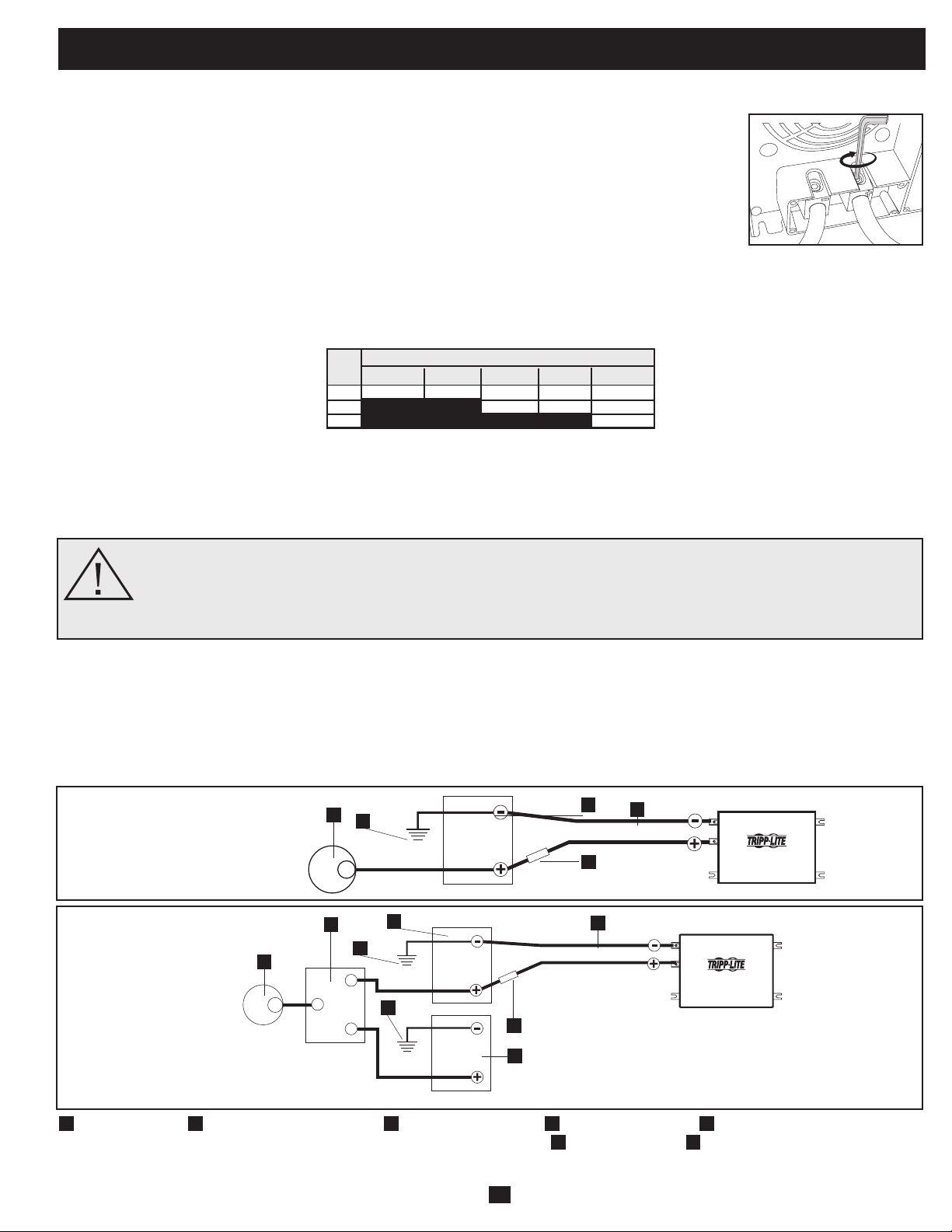
21
No vehicular o Vehicular
Elvoltajenominaldeentradadecorrientecontinuadesuinversor/cargadordebecoincidirconelvoltajedesubateríaobaterías-12
voltiosenlamayoríadelasaplicaciones.
Aunque es posible conectar su inversor/cargador a la batería principal del sistema eléctrico de su vehículo, en una situación normal
vehicular, el inversor/cargadorse conecta a una o más baterías auxiliares dedicadas que están aisladas del sistema motriz para evitar
cualquierposibleconsumodelabateríaprincipal.
Conexión de batería
• Conexión del cableado de corriente continua: Aunque su inversor/ cargador es un convertidor de
electricidaddealtaeficiencia,sucapacidaddesalidaestálimitadaporlalongitudycalibredelcableado
desdelabateríahastalaunidad.Uselalongitudmáscortayelcalibredemayordiámetrodelcableado
(máximocalibre2/0)parainstalarlosterminalesdeentradadecorrientecontinuadesuinversor/cargador.
Uncablemáscortoydemayorcalibrereducelacaídadevoltajedecorrientecontinuaypermitelamáxima
transferenciadecorriente.Suinversor/cargadorpuedeentregarunapotenciamáximahastade200%desu
salidadepotenciapermanentenominalporbrevesperíodosdetiempo.Debeusarseunmayorcalibrede
cablecuandoseopereenformapermanenteconequiposdealtoconsumobajoestascondiciones.Apriete
losterminalesdesuinversor/cargadorysubateríahasta3.5Newton-metrosdetorque,aproximadamente,
paracrearunabuenaconexiónyparaevitarelexcesivocalentamientodelamisma.Unaprieteinsuficiente
delosterminalespodríaanularsugarantía.(Vealatablaabajo.)
Máximo recomendó longitud de cable CC
Conecte su inversor/cargador a sus baterías usando los siguientes procedimientos:
¡ADVERTENCIA!•Noponeratierracorrectamentesuinversor/cargador,conectandoalchasisdelvehículooa
la tierra del sistema, puede producir un choque eléctrico letal.
• Nuncatratedeoperarsuinversor/cargadorconectándolodirectamentealasalidadeunalternadorenlugarde
a una batería o banco de baterías.
• Observelapolaridadcorrectacontodaslasconexionesdecorrientecontinua.
12 Volt Inverter/Charger
12 Volts
12 Volts
3
5
Conexión de batería primario 12 VCC
1
Alternador 12 VCC
2
Tierra de la batería del vehículo
3
Batería primario 12 VCC
4
Batería auxiliar 12 VCC
5
Fusible y bloque de fusibles
certificados por UL (montados a una di tancia dentro de 45 cm (18 pulgadas) de la batería)
6
Aislante de la batería
7
Cable de gran diámetro, máximo calibre
2/0 para instalar terminales
12 Volt Inverter/Charger
12 Volts
12 Volts
12 Volts
Conexión de batería primario y batería auxiliar 12 VCC (paralelo aislado)
1
4
1
7
6
2
2
5
7
3
2
Conectores de corriente continua
Calibre del Cable (AWG)
Salida 6 4 2 0 00 (2/0)
750W 10 pies 16 pies 26 pies 42 pies 52 pies
1250W No Usar No Usar 16 pies 25 pies 31 pies
2000W No Usar No Usar No Usar No Usar 20 pies
Distancia Máxima de la Batería al Inversor/Cargador
Advertencia: No use un calibre menor de 6 AWG.
•Conexión defusible:Elartículo551delCódigoEléctricoNacional(NEC)exigeconectartodoslosterminalesdecorrientecontinua
positivosdesuinversor/cargadordirectamenteafusiblesybloque(s)defusiblescertificadosporUL,aunadistanciadentrode45cm(18
pulgadas)delabatería.LacapacidaddelfusibledebeserigualomayorquelaMínimacapacidadfusibleCCindicadaenlasespecificaciones
desuinversor/cargador.Vealosdiagramasdeabajoparalacorrectacolocacióndelosfusibles.
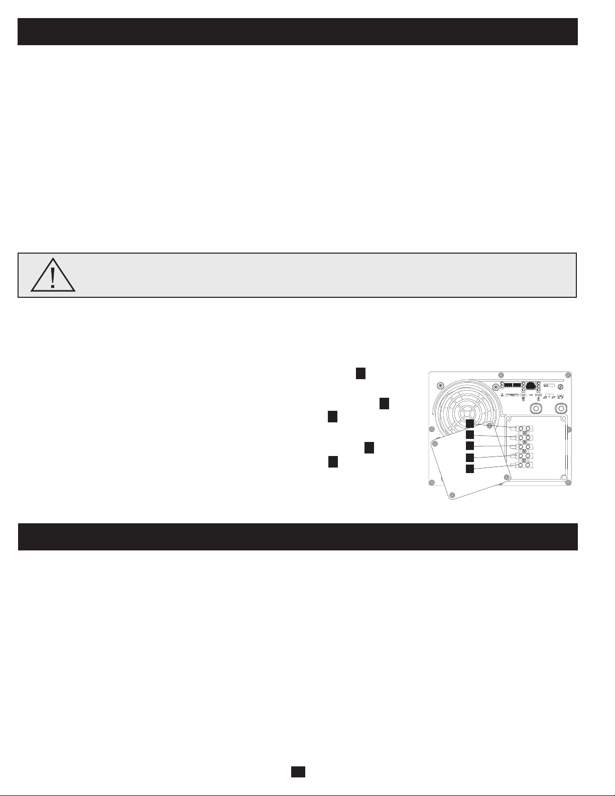
22
Conexión de entrada/salida de corriente alterna
Paraevitarsobrecargarsu inversor/cargador, asegúresede cumplir losrequisitos de potenciadel equipo que planea operar en cualquier
momentoalavez(sumesuspotenciastotales)conlacapacidaddepotenciadesalidadelmodelodesuinversor/cargador(vealasección
Nameplate)Cuandoestimelosrequisitosdepotenciadesuequipo,noconfundapotencia"permanente"conpotencia"pico".Lamayorparte
demotoreseléctricosrequierepotenciaadicionalenelarranque(potencia"pico")alanecesariaparafuncionarenformapermanentedespués
delarranque,avecesdeun100%omás.Algunosmotores,comoenrefrigeradoresybombas,arrancanysedetienenenformaintermitente
deacuerdoconlademanda,requiriendounapotencia"pico"variasveces,enformaimpredecible,durantesuoperación.
Función OverPower
™
Los inversores/cargadores de Tripp Lite entregan hasta el 150% de su potencia nominal de placa con autonomía de 1-60 minutos bajo
condiciones de batería y temperatura ideales*, proporcionando amplia energía de reserva para sostener la operación de herramientas y
equipos.
* Para mejores resultados, utilice OverPower por el período de tiempo más corto posible, asegúrese que el banco de baterías y el cableado puedan proporcionar voltaje nominal de corriente continua total bajo carga y permita que
el inversor/cargador se enfríe por completo antes y después de utilizar OverPower.
Función DoubleBoost
™
Losinversores/cargadoresdeTrippLiteentreganhastadosvecessupotencianominaldeplacaporhasta10segundos,*proporcionandola
potenciaadicionalnecesariaparaelarranqueenfríodeherramientasyequiposdeserviciopesado.
* La duración real depende de la antigüedad de la batería, el nivel de carga y la temperatura ambiente.
¡Advertencia!Consulteconunelectricistacalificadoysigaloscódigoseléctricosyrequisitosaplicablespara
la conexión cableada. Desconecte la entrada de corriente continua y el suministro de corriente alterna de la
red antes de realizar el cableado.
Conexión terminales cableados
Retirelostornillosylaplacadecubiertadelacajadeterminales.Retirelascubiertasdelosagujerosciegosmáscercanasalafuente
eléctricadeseadayasuequipo.Conectetubosde½"diámetro(suministradosporelusuario)alosagujerosciegosypaselosconductores
atravésdeellos.Conectelostubosentresíconlaconexióndetierrasuministrada.
Tierra*
• Conectelosconductoresdetierraentranteysalientealterminaldetierra(verde).
Entrada de corriente alterna
• Conecteelconductorentrantecontensiónalterminaldeentradacontensión(marrón).
• Conecteelconductorneutroentrantealterminalneutrodeentrada(azul).
Salida de corriente alterna
• Conecteelconductorsalientecontensiónalterminaldesalidacontensión(negro).
• Conecteelconductorneutrosalientealterminalneutrodesalida(blanco).
• Coloquelaplacadecubiertayaprietelostornillos.
*Si el tubo entrante sólo contiene dos conductores (con tensión y neutro), debe estar conectado a la oreja principal de tierra en la unidad. En cualquier caso, el tubo
entrante debe estar conectado a tierra o a la tierra del vehículo, y el tubo entrante debe estar conectado al tubo saliente.
1
2
3
4
5
Servicio
Antesdeenviarsuinversor/cargadorparaqueleprestenservicio,sigalossiguientespasos:1.)Verifiquelasinstruccionesdeinstalacióny
operación en este manual para asegurarse que el problema deservicio no sea causado por una mala interpretación de las instrucciones.
Además,verifiquequelos interruptoresautomáticos delinversor/cargadorno hayansido disparados.*2.) Siel problemacontinúa, no
contacteconeldistribuidornidevuelvaelinversor/cargador.Ensulugar,llameaTrippLiteal+17738691233.Untécnicodeserviciole
pediráelmodelo,númerodeserieyfechadecompradelinversor/cargadorytrataráderesolverelproblemaatravésdelteléfono.3.)Siel
problemarequiereservicio,eltécnicoleemitiráunnúmerodeAutorizacióndedevolucióndemercadería(RMA),necesarioparaquele
presten servicio. Empaque el inversor/cargador firmemente para vitar daños durante el despacho. No use camas de Styrofoam para
embalaje.**Cualquierdaño(directo,indirecto,especial,accidentaloresultante)alinversor/cargadorproducidoduranteeldespachoaTripp
LiteoauncentroautorizadodeservicioTrippLitenoestácubiertoporlagarantía.Losinversores/cargadoresenviadosaTrippLiteoa
algúncentrodeservicioautorizadodeTrippLitedebentenerloscargosdetransporteprepagados.MarqueelnúmeroRMAenlaparte
externadel paqueteembalado. Si elinversor/cargadorestá dentro del período de garantía, adjunte unacopia de surecibo de compra.
Devuelvaelinversor/cargadorparaservicioaladireccióndadaporeltécnicodeTrippLiteutilizandountransportistaasegurado.
* Esta es la causa más común de pedidos de servicio que pueden ser solucionados fácilmente siguiendo las instrucciones de restablecimiento en este manual.** Si requiere embalaje, el técnico puede hacer arreglos para que le
envíen el embalaje adecuado.
OUTPUT/NEUTRAL
OUTPUT/HOT
INPUT/NEUTRAL
INPUT/HOT
GROUND
“FOR USE WITH COPPER WIRE ONLY”
5
4
1
3
2
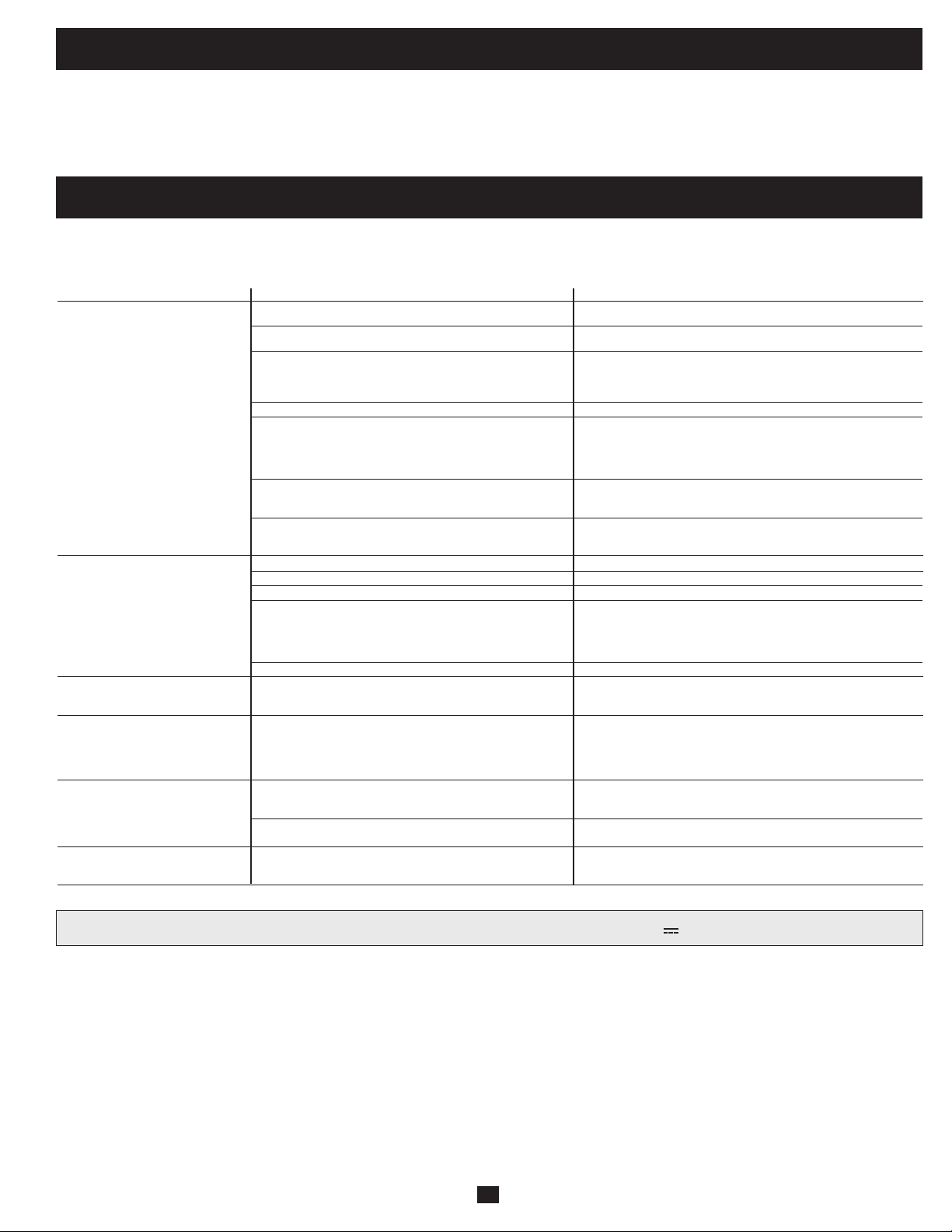
23
Remarque sur l'étiquetage Deux symboles sont utilisés sur les étiquettes de VR. V~: voltage CA V : voltage CC
Mantenimiento
Solución de problemas
SÍNTOMA PROBLEMAS CORRECCIONES
No hay salida de corriente alterna La unidad no está conectada correctamente a la energía de Conecte la unidad a la energía de la red.
(Todas las luces indicadoras están la red
APAGADAS) El conmutador de modo de operación está fijado en "DC OFF" y Fije el conmutador de modo de operación a "AUTO/REMOTE" o
hay entrada de corriente alterna. "CHARGE ONLY."
Esto es normal cuando el Conmutador de modo de operación No se requiere ninguna corrección. La salida de corriente alterna regre
se fija a "CHARGE ONLY" y no hay entrada de corriente alterna. sará cuando regrese la entrada de corriente alterna. Fije el conmutador
de modo de operación a "AUTO/REMOTE" si requiere salida de
corriente alterna.
El interruptor automático de salida ha disparado. Restablezca el interruptor automático.
La unidad se ha apagado debido a sobrecarga de la batería Desconecte cualquier cargador auxiliar. Restaure moviendo el
(evitando daños a la batería) Puede haber un problema con los Conmutador de modo de operación a "DC OFF."Espere 1 minuto y cambie
cargadores auxiliares conectados, si hay alguno, o con a "AUTO/REMOTE" o "CHARGE ONLY." Si la unidad permanece en modo
el cargador de la unidad. apagado después de varios intentos de restaurar, contacte con el
Servicio al cliente de Tripp Lite para recibir asistencia técnica.
La unidad se ha apagado debido a una descarga excesiva de Use un cargador* auxiliar para elevar el voltaje de la batería. Revise las
la batería. conexiones de la batería externa y los fusibles. La unidad se restaura
automáticamente cuando se elimina la condición.
La unidad se ha apagado por una sobrecarga. Carga reducida. Restaure moviendo el Conmutador de modo de
operación a "DC OFF." Espere 1 minuto. Cambie a "AUTO/REMOTE" o
"CHARGE ONLY."
La batería no está recargando Las baterías conectadas están descargadas. Revise y reemplace las baterías viejas.
(Hay entrada de corriente alterna) El fusible de la batería* está fundido. Revise y reemplace el fusible.*
El cableado* de la batería está flojo. Revise y ajuste o reemplace el cableado.*
La unidad se ha apagado debido a sobrecarga de la batería Desconecte cualquier cargador auxiliar. Restaure moviendo el
(evitando daños a la batería) Puede haber un problema con los Conmutador de modo de operación a "DC OFF."Espere 1 minuto y cambie
cargadores auxiliares conectados, si hay alguno, o con el a "AUTO/REMOTE" o "CHARGE ONLY." Si la unidad permanece en modo
cargador de la unidad. apagado después de varios intentos de restaurar, contacte con el
Servicio al cliente de Tripp Lite para recibir asistencia técnica.
El interruptor automático de cargador ha disparado. Restablezca el interruptor automático.
Las tres luces indicadoras de batería La batería está demasiado descargada. Use un cargador* auxiliar para elevar el voltaje de la batería. Revise las
destellan lentamente (destellos de ½ conexiones de la batería externa y los fusibles. La unidad se restaura
segundo) automáticamente cuando se elimina la condición.
Las tres luces indicadoras de batería La batería está sobrecargada. La unidad se apagará para evitar Desconecte cualquier cargador auxiliar. Restaure moviendo el
destellan rápidamente daños a la batería. Puede haber un problema con los cargadores Conmutador de modo de operación a "DC OFF."Espere 1 minuto y cambie
(destellos de ¼ de segundo) auxiliares conectados, si hay alguno, o con el cargador de a "AUTO/REMOTE" o "CHARGE ONLY." Si la unidad permanece en
la unidad. modo apagado después de varios intentos de restaurar, contacte con el
Servicio al cliente de Tripp Lite para recibir asistencia técnica.
Luz roja "LOW" de batería baja El voltaje de la batería está bajo. La unidad se apagará Asegúrese de que haya energía de corriente alterna para recargar las
La luz indicadora está destellando automáticamente después de 5 segundos para proteger la baterías. Restaure moviendo el Conmutador de modo de operación a
batería contra daños. "DC OFF y luego a "AUTO/REMOTE" o "CHARGE ONLY."
Falsa lectura debido a cableado de corriente continua muy Use un cable de corriente continua de calibre suficiente conectado al
pequeño o mal conectado. inversor/cargador.
Luz roja indicadora de operación "LOAD" El inversor está sobrecargado. La unidad se apagará Carga reducida. Restaure moviendo el Conmutador de modo de
destellando automáticamente después de 5 segundos. operación a "DC OFF." Espere 1 minuto. Cambie a "AUTO/REMOTE" o
"CHARGE ONLY."
Suinversor/cargadornorequieremantenimientoynocontienepartesreemplazablesoalasqueelusuariopuedadarservicio,perosiempre
debemantenerseseco.Revise,limpieyaprieteperiódicamentetodaslasconexionesdecablessegúnseanecesario,tantoenlaunidadcomo
enlabatería.
Pruebeestassolucionesparaproblemascomunesdelinversor/cargadorantesdellamarparaayudatécnica.LlameaServicioalclientede
TrippLite,al(773)869-1234antesdeenviarsuunidadparaservicio.

200904174 93-2748-ES
24
Tripp Lite garantiza que su inversor/cargador está libre de defectos en materiales y mano de obra por un período de un año (excepto fuera de EE.UU., Canadá y México-120
días) desde la fecha de compra por parte del usuario final. Bajo esta garantía, la obligación de Tripp Lite está limitada a reparar o reemplazar (a su opción) cualquier producto
defectuoso. Para obtener servicio bajo esta garantía, debe conseguir un número de Autorización de devolución de mercadería (RMA) de Tripp Lite o de un centro de servicio
autorizado de Tripp Lite. Los productos deben ser devueltos a Tripp Lite o a un centro de servicio autorizado de Tripp Lite con los cargos de transporte pagados por adelantado y
deben estar acompañados de una breve descripción del problema encontrado y un comprobante de la fecha y el lugar de compra. Esta garantía no se aplica al equipo que ha
sido dañado por accidente, negligencia o uso inadecuado, o que ha sido alterado o modificado en cualquier forma, incluyendo la abertura de la caja de la unidad por cualquier
motivo. Esta garantía solamente se aplica al comprador original que debe haber registrado correctamente el producto dentro de los 10 días de la compra. SALVO POR LO
ESTABLECIDO EN ESTE DOCUMENTO, TRIPP LITE NO EXPRESA NINGUNA GARANTÍA, EXPRESA O IMPLÍCITA, INCLUYENDO GARANTÍAS DE COMERCIABILIDAD O
IDONEIDAD PARA UN PROPÓSITO PARTICULAR. Algunos estados no permiten limitaciones o exclusiones de las garantías implícitas; por lo tanto, las limitaciones o
exclusiones mencionadas anteriormente pueden no aplicarse al comprador. SALVO POR LO ESTABLECIDO ARRIBA, EN NINGÚN CASO TRIPP LITE SERÁ RESPONSABLE
POR DAÑOS DIRECTOS, INDIRECTOS, ESPECIALES, INCIDENTALES O EMERGENTES, RESULTANTES DEL USO DE ESTE PRODUCTO, AUN EN EL CASO DE
HABERSE INFORMADO DE LA POSIBILIDAD DE DICHOS DAÑOS. Específicamente, Tripp Lite no es responsable por ningún costo, como pérdida de ingresos o beneficios,
pérdida de equipos, pérdida de uso de equipos, pérdida de software, pérdida de datos, costos por reemplazos, reclamaciones de terceras partes, o lo que corresponda. Tripp Lite
tiene una política de mejoramiento continuo. Las especificaciones están sujetas a cambio sin previo aviso.
Cumplimiento de las normas de los números de identificación
Para fines de identificación y certificación del cumplimiento de las normas, su producto Tripp Lite tiene asignado un número de serie único. Puede encontrar el número de serie
en la etiqueta de la placa de identificación del producto, junto con los símbolos de aprobación e información requeridos. Al solicitar información sobre el cumplimiento de las
normas para este producto, siempre mencione el número de serie. El número de serie no debe ser confundido con el nombre de identificación ni con el número de modelo del
producto.
Tripp Lite tiene una política de mejoramiento continuo. Las especificaciones están sujetas a cambio sin previo aviso.
Fabricado en China.
Garantía limitada
1111 W. 35th Street, Chicago, IL 60609 USA
Soporte al cliente: 773.869.1234
www.tripplite.com