CONTENTS
TECHNICAL CHARACTERISTICS.........................................1
BODY SIZE ....................................................................................1 -2
MAIN PARTS NAME .......................................................................2
I N S TA L L AT I O N R E Q U I R E M E N T. . . . . . . . . . . . . . . . . . . . . . . . . . . . . . . . . . . . . . 3
INSTALLATION PROCEDURES..........................................4-5-6-7-8
OPERATING INSTRUCTION..............................................9-10-11
MA I N T E N A N C E . . . . . . . . . . . . . . . . . .. . . . . . . . . . . . . . . . . . . . . . . . . . . .. . . . . . . . . . . . . . . . . 1 2
IMPORTANT SAFETY INSTRUCTIONS..................................14-15
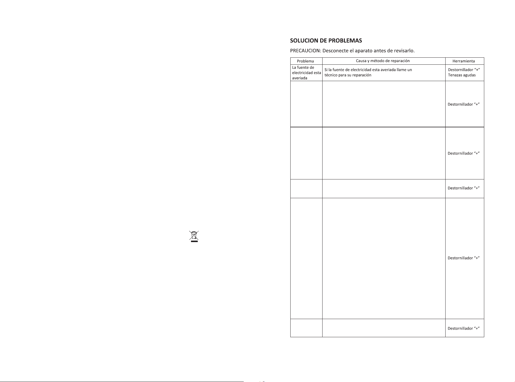
TROUBLE SHOOTINGS.................................................................16
TO R E P L ACE L IGHT BULB.. . . . . .............. . . . . ............... . . . . ....12
I M P O RTA N T N O T I C E . . . . . . . . . . . . . . . . . . . . . . . . . . . . . . . . . . . . . . . . . . . . . . . 1 3
READ AND SAVE THESE INSTRUCTIONS MANUAL
Please not e t h a t t h i s product is m a r k e d w i th this symb o l :
Accordin g t o Wa s t e o f Electric a l a n d E l e ctronic Eq u i p m e n t
(WEEE) dir e c t i v e , WE E E s h ould be sepa r a t e l y c ollected a n d
treated. I f a t a n y t i m e in future yo u n e e d t o d i spose of thi s
product, P l e a s e d o N OT di s p ose of this pr o d u c t w i th house hol d
waste. Ple a s e s e n d t his produc t t o WEEE colle c t i n g p o ints where
availabl e .
16
Poca
Potencia
de succión
El motor no
arranca
Vibracion
de
la unidad
Gran ruido
Bombillo no
funciona
a) El motor no funciona, reemplace con un nuevo
motor.
b) El interruptor de control no funciona,reemplace
con un nuevo interruptor.
c) La capacitancia no funciona, reemplace una
nueva capacitancia.
a) La instalación no está suficientemente firme.
Revise y este seguro que está firme lo suficiente.
b) El ventilador no funciona, entonces no esta
balanceado. Reemplace un nuevo motor.
c) El motor no está firme. Revíselo e instálelo
suficientemente firme.
a)Si algunas particulas caen dentro del
b)soplador. Revise y límpielo.
a) La distancia desde la campana hasta la cocina
es muy grande. Este seguro que la distancia sea de
650-700mm.
b) Hay muchas ventanas o puertas en la cocina, la
convección de aire es muy grande. Cierre algunas
puertas o ventanas, para disminuir la convección
del aire.
c) Hay existencia de poco viento en el tubo de
escape. Hacer que la salida del tubo de escape
quede hacia abajo.
d) Disminución de la tasa de arranque.Reemplace
un nuevo motor o capacitancia. Debido a que la
campana se sitúa encima de la ventana, la mejor
solución es poner tres capas de alguna especie de
tabla en la parte de atrás de la campana para cubri
el hueco de la ventana.
Reemplace con una nueva lampara led.
1
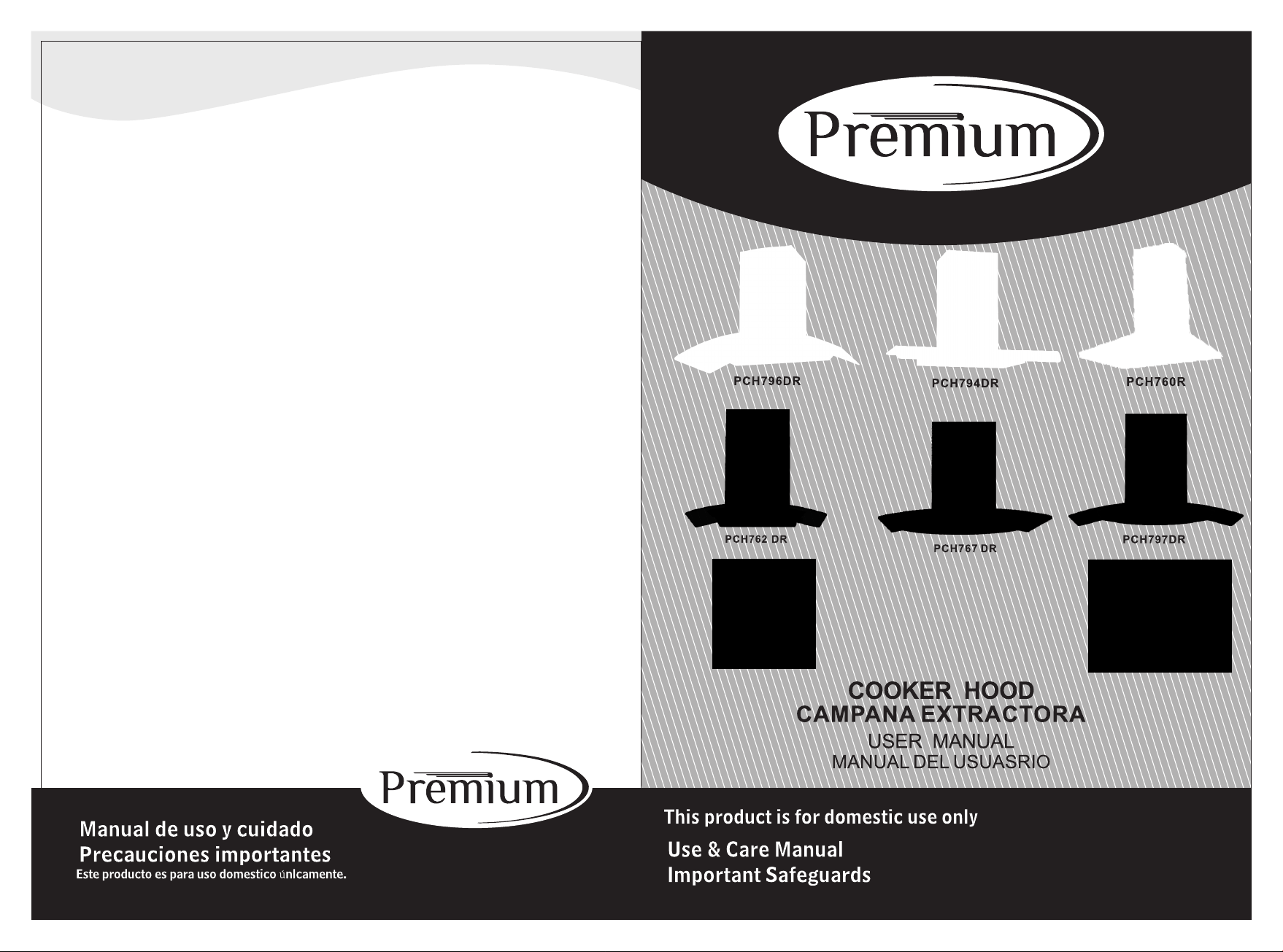
Dear consumer,
Thanks for your purchase of our cooker hood and we hope we can fully
satisfy all of your needs. Please read entire instructions carefully before
proceeding to obtain the best results of using the cooker hood.
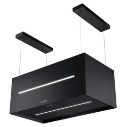
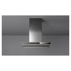
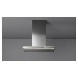
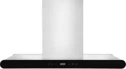
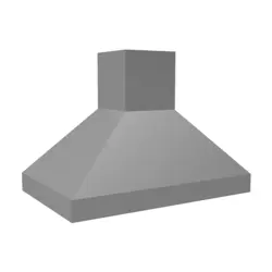
Model no.: □PCH796DR □PCH794DR □PCH760R □PCH762DR
□PCH767DR □PCH797DR
Total power: □190W □154W
Three speed motor: □150W
LED lights: □2×2W Normal lights: □2×25W
Voltage: 110~120 V Frequency: 60HZ
Filter: □6-layer filter
Control: □3speed □3speed Push button
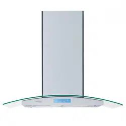
□PCH990R □PCH960R □PCH896IR
□158W
Highly-sensitive touch video switch
TECHNICAL CHARACTERISTICS
BODY SIZE
PCH760R 63160不带 方边1 50风 机
597
487
189
530- 920
186
213
200
180
A
B
PCH762DR 6 6 8S ( 6 0)/ G S 14
295
285
509-900
59
475
595
PCH794DR
30
0
283
895
480
500- 880
PCH767DR 688(60)/GS14
15
Glove
Use un guante de proteccion
autes de empezar a limpiar la
campana. Remueva los
componentes suavemente
durante la limpieza.
Nunca lave el interruptor de
control con agua u otro liquido
para evitar que el liquido
pueda causar un dano electrico
en el aparato.
La limpieza del ventilador
del motor debe ser hecha
por una persona calificada.
Ponga mucha atencion para
evitar danos en el ventilador
durante su limpieza.
Nunca desconecte el cable de
corriente con su mano
humeda para evitar el riesgo
de una descarga electrica.
Desconecte la campana
extractora de la fuente de
electricidad si el aparato no
se va a usar por un largo
periodo de tiempo.
595
480
48
483-873
283
300
A
B
232
339
341
232
A
B
A
B
PCH797DR 688/GS14
895
480
500-880
300
283
341
232
A
B
A
B
PCH796DR
300
283
525-920
115
475
895
2
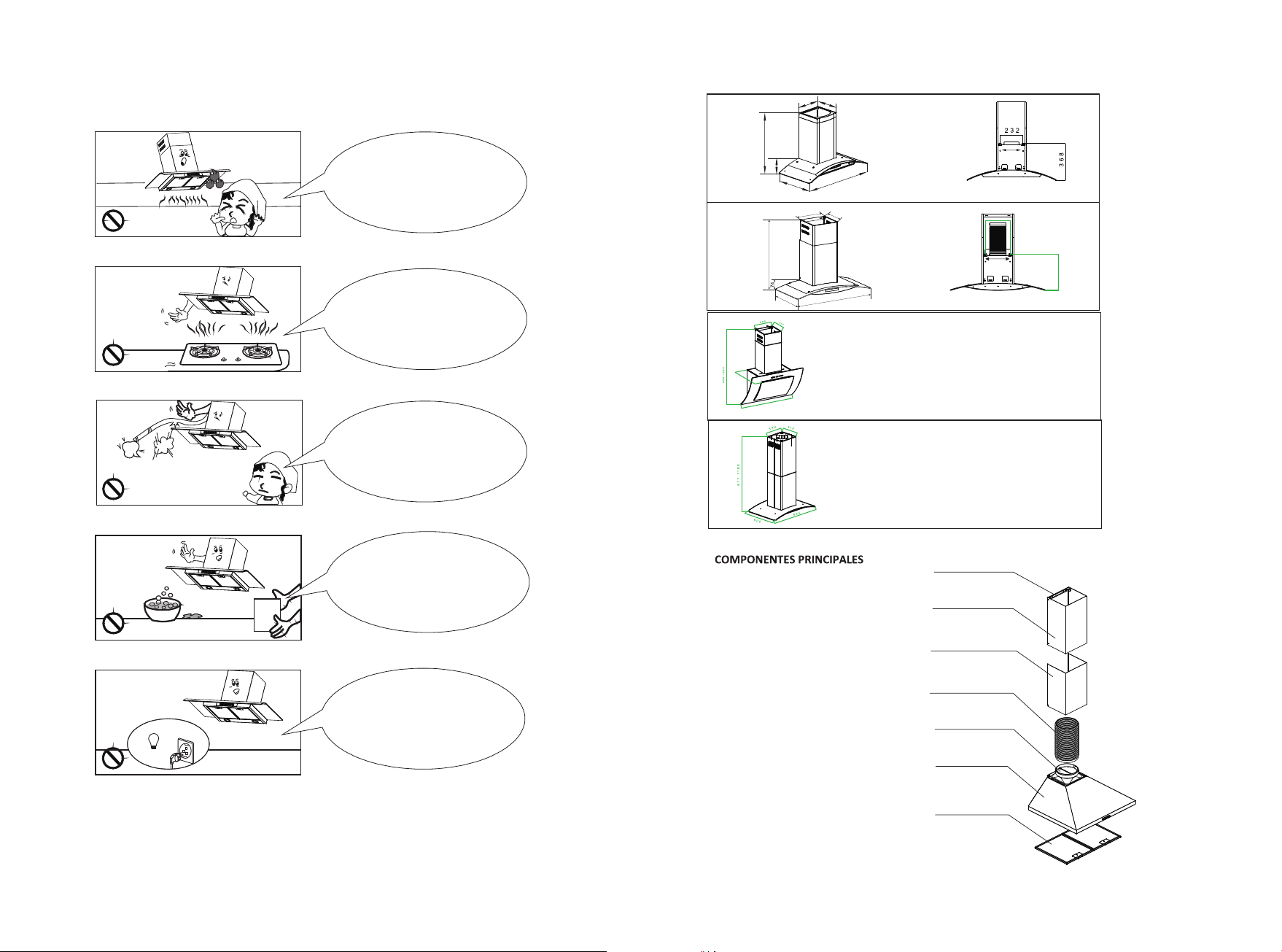
MAIN PARTS NAME
Inner telescopic-duct
Outer telescopic-duct
Aluminium filter
Exhaust pipe
Bottom cover
Duct bracket
Air outlet
14
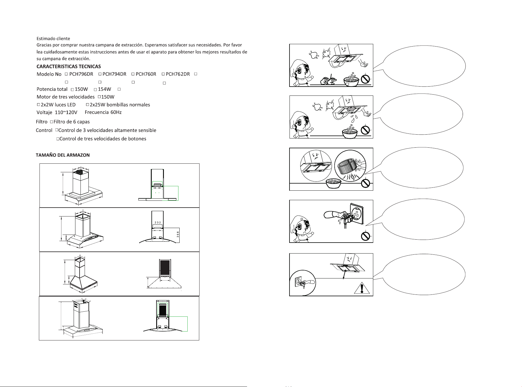
Manual
Limpie la campana de
acuerdo a las instrucciones
dadas para evitar incendios.
La bombilla debe ser reemplazada
por un tecnico calificado. Use
bombillas de vatios igualeso
menores al estipulado.
En caso de danos al cable de
corriente, solicite a un
tecnico que lo repare.
No conecte la salida de
aire a chimeneas ni
ductos de combustion
de gas
No permita que arde fuego
(llamas) bajo la campana
59 5 / 8 9 5
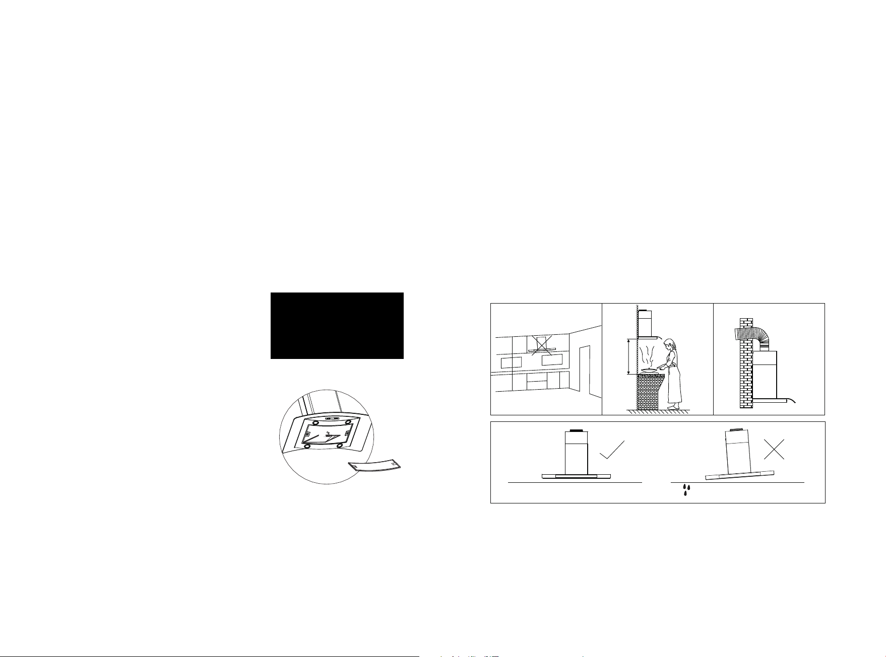
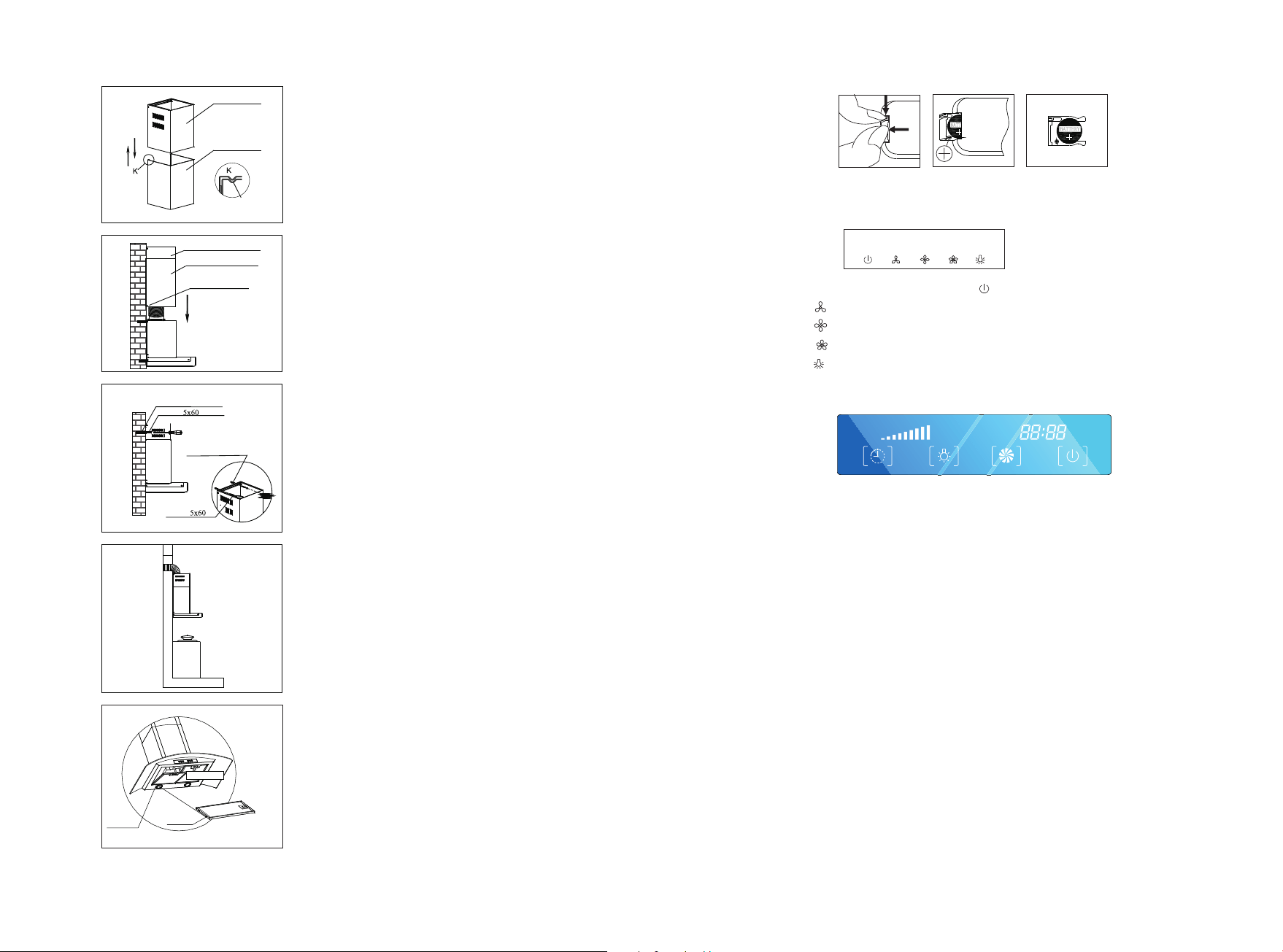
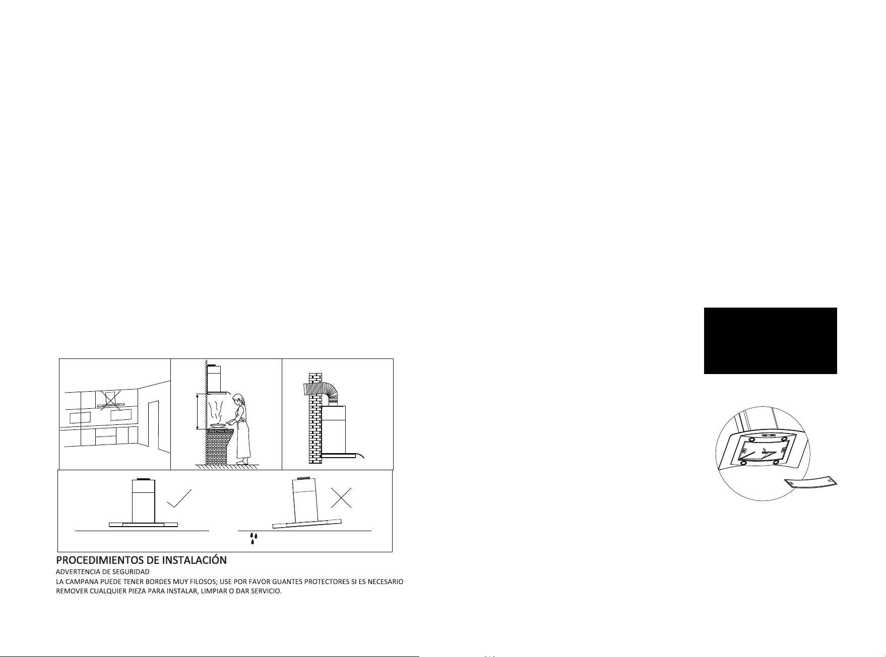
INSTALLATION REQUIREMENT
1. Do not install the cooker hood where there are many doors or windows in other to avoid to
effecting the exhaust efficiency of the hood caused by air convection. (Fig. 1)
2. Install the cooker hood right above the hob. The recommended distance between the hob and
the lower edge of the cooker hood PCH 760R,PCH762DR,PCH767DR,PCH797DR,PCH794DR
PCH 796DR and PCH 896IR is minimum 650mm and maximum 700mm. (Fig. 2)
The recommened distance between the hob and the lower edge of the cooker hood
of PCH 990R and PCH 960R is minimum 350mm and maximum 400mm.(Fig.2)
3. In order to get the optimum performance, do not elongate the exhaust pipe too long, and try
to make the bend of exhaust pipe less and biggest, ensure the connection is airproof.(Fig. 3)
4. After hanging the unit on the wall, ensure the hood is level and vertical.(Fig. 4)
5. The air outlet must not be connected to chimney flues or combustion gas
ducts. The air outlet must under no circumstances be connected to venti-
lation ducts for room in which fuel-burning appliances are installed.
LEVEL
Fig.4
LEAN
650~700 mm/
350-400 mm
Fig.1 Fig.2 Fig.3
INSTALLATION PROCEDURES
SAFETY WARNING
HOOD MAY HAVE VERY SHARP EDGES; PLEASE WEAR
PROTECTIVE GLOVES IF IT IS NECESSARY TO REMOVE ANY
PARTS FOR INSTALLING, CLEANING OR SERVICING.
6.The cooker hood can be installed either in Re-circulation mode or Ducting
mode. All the models already install charcoal filters in re-circulation mode.
If you want ducting mode, then take out the charcoal fitlers.
3
13
*Fig
Es aconsejable llamar a una persona de servicio calificada y autorizada para
limpiar periódicamente el ensamble interno; así seria una gran mejora para
el rendimiento de los productos.
Nota: si por alguna razón, no usa la campana, el aceite puede que se deposite
la superficie y filtro de la chimenea y pueda iniciarse un goteo produciendo
fuego en la misma.
Nota: Antes de realizar el mantenimiento o el reemplazo de la lámpara,
desconecte la campana de la fuente principal (despegue el enchufe del sócate).
Modo ducción
No necesita instalar filtros de carbón, posee
escape exterior. Si puede ubicar un escape
exterior entonces le sugerimos que seleccione
este modo para un mejor rendimiento.
Cualquiera q sea el modo que usted seleccione
sea el de recirculación o el de ducción, filtros
de casete necesitan ser limpiados todo los meses,
pero puede que varíe el patrón de uso también. En
caso de que una gran cantidad de aceite sea usado para cocinar, igual debe ser
limpiado cada semana por noche. Filtros pueden ser fácilmente limpiados, solo
póngalos en una solución de jabón y agua caliente, limpiándolos con un cepillo
y enjuagándolos con agua corriente del grifo, luego séquelo con un paño seco.
Rearme los filtros apropiadamente, sáquelos y colóquelos mediantes
instrucciones, presionando el seguro del filtro hacia atrás para liberar el filtro
de la ranura.
Nota Importante
A
Modo de recirculación
Chequee que el filtro de carbón activado estén ajustados apropiadamente, así
las impurezas pueden ser efectivamente absorbidas.
La campana funcionara mejor a la velocidad de segundo o más baja a modo de
tener tiempo suficiente para la filtración del aire. Los filtros de carbón no
pueden ser reutilizados, necesitan ser cambiados periódicamente. La vida útil
de los filtros de carbón son aproximadamente 3 a 4 meses. Sin embargo, si la
campana es usada por más de 4 horas en un día y se usa una gran cantidad de
aceite mientras cocina puede que el filtro de carbón
requiera cambios más frecuentes.
El filtro de carbón tiene que ser cambiado
tan pronto sea saturado. Ellos pueden ser
fácilmente reemplazados, girándolos en
sentido anti horario para sacarlos y horario
para colocarlos.
Nota: El uso de filtros de carbón opcional o modo duccion se deja al instalador.
INSTALLATION FOR MODEL PCH760R,PCH762DR,PCH794DR,PCH796DR,
PCH767DR,PCH797DR
Wood Screw
5x60
Expanding Tube
Hook
232mm
different
B
A
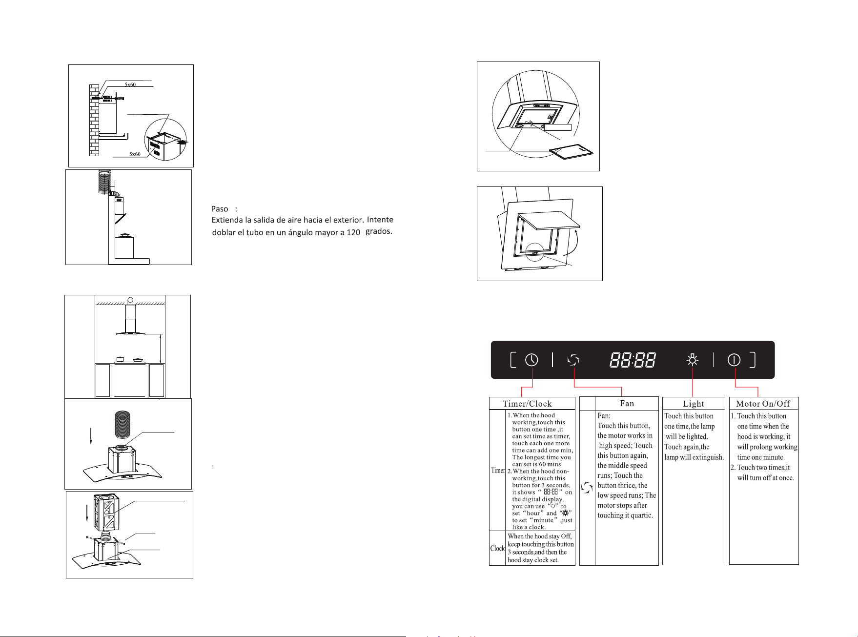
Step 2:
According the space between the hole
A&B,drill 2 holes in level on the wall with
8mm in diameter and 60-70mm in depth.
Press the 2 expanding tube provided into
the holes. Tighten the 2 wood screws of
5x60mm which supplied together with the
hood to the expanding tube.Make sure it is
fixed enough and cannot be move.Hang the
cooker hood on the 2 wood screws,make
sure it is to be level and stable.
Exhaust pipe
Air outlet
Step 3:
Take out the cooker hood from the carton
and put it on a horizontal work table gently.
Fix the reducerpipe into the air outlet of the
inner duct, and then fix the exhaust pipe into
the top of reducer,make sure it is connected
to the reducer tightly.
Step 4:
Matching the bracket to the holes of the
inner duct and fix it well with M4
screws.
Step 1:
Please put the cooker hood on the wall and
mark the position where you want to install.
We recommend the height from the hob to
the lower edge of the hood should be from
650mm to 700mm.
10mm
650-700mm
Bracket
Inner duct
M4 Screw
A
B
Expanding Tube
Back of the hood
5x60
Wood Screw
4
12
5
Step 5:
Insert the inner duct into the outer
duct . Please kindly note that the
inner duct must fix to the outer duct ’s
orientation slot.
Step 6:
Put the outer duct to the unit body,
and use two M4x10 screwsto fix the
outer duct to the unit body.
Step 8:
Extend the air outlet of the exhaust
pipe out-of-door. Try to make the
bend of the exhaust pipe is more than 120。.
Step 9:
Install grease filter. Match the fix pin to
the fix hole and button the filter gently as
the direction of arrow A.
Fix pin
Fix hole
A direction
Inner duct
Outer duct
K
K
Orientation Slot
Inner duct
Outer duct
fix screws
5x60
Wood Screw
Expanding Tube
5x60
Wood Screw
Expanding Tube
Step 7:
1. Draw the inner duct up to the
suitable high, mark on the wall two keyhole
of the outer duct bracket with a pen .
2. Put down the inner duct gently, drill
the keyholes in 60-70mm depth on the
horizontal level using 8mm drill.
3. Press the expanding tube provided into
the holes.
4. Matching the inner duct with the holes,
tighten the inner duct cover with two 5x60
wood screw provided
A: Reloj
1.
PCH896IR
A
B C D
A B C D E
Pic 1 Pic 2 Pic 3
60 min u t o s
2.
A
B
C
C:
D:
Wood Screw
5x60
Expanding Tube
Hook
A B
C
D
306
310
Step 1:
Please put the cooker hood on the wall and
mark the position where you want to install.
We recommend the height from the hob to
the lower edge of the hood should be from
350mm to 400mm.
10mm
350-400mm
Installation For Model PCH 990R,PCH 960R
Step 2 For Model PCH 990R ,PCH 960R
Drill holes in the wall using a 8 mm drill bit.Use
three screws to fit the hook on the wall in the screw
holes 1,2,3 .Then use one M4X10 screw fit the
appliance on the screw hole 4 to make sure the
appliance is fixed and can not be moved!
3
2
165
229
250
40
Wood Screw
5x60
Expanding Tube
Hook
1
4
Inner duct
Outer duct
K
K
Orientation Slot
Inner duct
Outer duct
fix screws
Step 3:
Insert the inner duct into the outer duct .
Please kindly note that the inner duct
must fix to the outer duct ’s orientation
slot.
Step 4:
Put the outer duct to the unit body, and use
two M4x10 screwsto fix the outer duct to
the unit body.
6
10
F
A
B
E
D
G
ABCDEF
&PCH990R&PCH960R
59
Step 6:
Extend the exhaust pipe to the vent-pipe of
your building or to outside. Try to make the
bend of the exhaust pipe is more than 120°.
5x60
Wood Screw
Expanding Tube
5x60
Wood Screw
Expanding Tube
Step 5:
1.Extend the inner chimney to the height
which you want . And mark the two holes of
the inner chimney’s hook on the wall.
2. Put down t
he inner duct cover gently, usin0-70 mm
depth on the wall which you marked just now.
3. Press the expanding tube into the holes.
4.Extend the inner chimney and tighen it to the
expanding tubes with two 5x60 wood screw .
g 8mm drill to drill two holes in
6
7
Installation For Model PCH 896IR
650-750mm
Step 1:
Fix the position of the chimney in accordance
with the recommended height between
650mm to750mm from the hob and the lower
edge of the chimney.
Air outlet
Reducer for
φ120 out-let
Low support frame
Screws
Blower box assembly
Step 3:
Aiming the Low support frame to the holes
on the blower box assembly , fix it tightly.
Then pull out the exhaust pipe to the level
of the low support frame.
Step 2:
Take out of the chimney from the carton
box and remove the filter,then put it on a
horizontal work table gently. Fix the
reducer to the airout let if needed .
Otherwise fix the exhaust pipe into the air
outlet,make sure is connected tightly.
9
Seguro
Paso 9
Instale el filtro piramidal, insertando los
seguros en los huecos y empuje suavemente
en la dirección A para adecuarlo.
A
Dirección
Precaución antes de cocinar:
Para los modelos PCH990R&PCH960R:
Cuando cocine, no necesita abrir el panel de
acero . Si usted quiere abrir el panel
cuando limpie el mismo, solo ábralo como
muestra la figura siguiendo la dirección que
muestra la fecha. Note que el panel no puede
cerrarse por sí solo después de abrirlo.
vidrio
Agujero de
fijaci nó
Perno de fijaci nó
PCH762DR Y PCH767DR Y PCH797DR
8
Upper duct cover
Low duct cover
Step 4:
Insert the upper duct cover into the low
duct cover.
Blower box assembly
Low duct cover
Upper duct cover
Step 5:
Put the upper and low duct cover on the
blower box assembly.Then pull out the
exhaust pipe to the level of the upper
duct cover.
Ceiling
Expanding Rubber
Expanding Screws
Ceiling cover
238
238
Step6:
As per the screw positions on the Upper
support frame, drill 4 holes (about φ8 mm) ,
then fill the Expanding Rubber into the
holes. Aiming the holes on the ceiling cover,
fix the ceiling cover with the expanding
screws tightly and make sure it is firm.
Step 7:
Put upper support frame under the ceiling
cover. Use screws to fix the upper support
frame to the ceiling cover.
Step 8:
Shift the complete chimney ,to make the
low support frame cover the upper support
frame. Adjust its height. Fix it tightly with
8 pcs M4x10 screws and make sure they are
firm.
Upper support frame
Screws
Low support frame
8
Paso 7
Ubique el soporte superior debajo de la
cubierta del techo y utilice tornillos para
fijarlo.
Paso 8
Deslice la chimenea de manera tal que cubra
el soporte fijado en el paso anterior.
Soporte superior
Tornillos
Soporte mas bajo
Techo
Tubo de expansi nó
Tubo de expansi nó
Cubierta del techo
238
238
Paso 6
En referencia a la posición de los tornillos en
el soporte superior, perfore 4 huecos
(alrededor de 8 mm de diámetro), luego llene
con las piezas de gomas expandibles en los
mismos. Apunte los huecos en la cubierta del
techo, ármela con los tornillos expandibles
de manera tal que quede firme.
Paso 5
Ponga la cubierta del ducto inferior y
superior antes armada encima de la caja de
soplado ensamblada. Luego hale la tubería
de gas hasta el nivel del ducto superior.
Cubierta del ducto externo
Cubierta del ducto interno
Ensamblaje de la
caja del ventilador
Cubierta del ducto interno
Cubierta del ducto externo
Paso 4
Inserte la cubierta del ducto superior en la
cubierta del ducto inferior.
9
Step 9:
Install pyramidical filter. Match the fix pin
to the fix hole and button the filter gently as
the direction of arrow A.
Filter
Fix hole
A direction
Caution before cooking:
FOR PCH 990R,PCH960R:
When cooking,no need open the glass panel.
If you want to open the panel when clean,
just open like this picture in the
arrow position tightly.Note that the panel
can’t fix itself after opening.
lock
OPERATION INSTRUCTION
PCH762DR & PHC767DR & PHC797DR
7
Paso 2
Saque la chimenea de la caja y quite el filtro,
luego póngalo sobre una tabla de trabajo
horizontal suavemente. Arme la tubería de
gas dentro de la salida de aire, este seguro
de que esté conectada fuerte de manera tal
que quede apretada.
salida de aire
Paso 3
Apunte el soporte inferior a los huecos en la
caja de soplado ensamblada, y luego ármela
de manera que quede apretada. Luego hale
la tubería de gas hasta el nivel del soporte
inferior.
Soporte inferior
Tornillo
Ensamblaje de la
caja del ventilador
Tubo de expansi nó
Tornillo de madera
Tubo de expansi nó
Tornillo de madera
Paso 5:
1)Extienda la cubierta interna a la altura
deseada. Marque dos orificios del gancho del
ducto interno en la pared.
2)Ponga la cubierta del ducto interno
suavemente usando una broca de 8 mm para
perforar dos orificios de 60-70 mm de
profundidad en la pared que usted acaba de
marcar.
3)Presione los tubos de expansión dentro de
los orificios
4)Extienda el ducto externo y apriete los dos
tornillos de madera 5x60 dentro de los tubos
de expansión.
INSTALACION PARA MODELOS PCH896IR
650-700mm
Paso 1:
Por favor ponga la campana en la pared y
marque la posición en la que la desea instalar.
Recomendamos que la altura desde la estufa
hasta la parte inferior de la campana debe ser
entre 650 mm hasta 700 mm.
6
PCH796DR&PCH990R&PCH960R
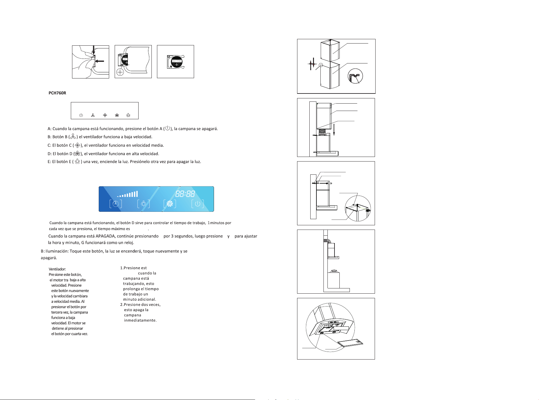
A: Touch A , the fan runs at the low speed. Press it again, the fan turns off.
B: Touch B, the fan runs at the mid speed. Press it again, the fan turns off.
C: Touch C, the fan runs at the high speed. Press it again, the fan turns off.
A、B、C three bottons interact.
D: When the hood stay OFF, keep touching D 3s, and then touch C and E to adjust hour
and minute, at that time, G just like a clock.
When the hood is operating , touch D to control working time of hood, 5 minutes per
one touch, the longest stay ON time is 60 minutes.
E: Touch E, torn on the light. Press it again, turn off the light.
F: When the hood is operating , touch F, the hood will not be OFF at once, it will stay
one minute, and then be OFF.
PCH794DR
This switch is highly-sensitive touch control, use your figure touch the key-press slightly to operate it.
And this switch with gas sensor and heater sensor function.
F
A
B
E
D
G
A. Motor on/off: Touch one time when the hood in working, it will
continue working one minute, touch again two times it will turn off.
B. Lighting: Touch this button, the light will be lighted, touch
again the light will be extinguish.
C. Receiver: Direct the remote control at the receiver when use.
D. High speed: Touch this speed, the motor will work in high speed.
E. middle speed: Touch this speed, the motor will work in middle speed.
F. Low speed: Touch this speed, the motor will work in low speed.
,
G. Timer: touch this button one time when it s in working condition,
it will turn off in one minute. Touch one more time, one more minute
working time increased.
change of electron
1.Open the electron cover,refer to pic 1.
2.When open,pls pay attention to the anode and cathode,refer to pic 2.
3.Take out the old electro and fix the new one and make sure the anode is as pic 3.
ABCDEF
10
6
Cubierta del ducto interno
Cubierta del ducto externo
Ranura de
orientación
Cubierta del ducto interno
Cubierta del ducto externo
Tornillos de fijaci n
para el ducto externo
ó
Paso 3:
Ponga el ducto interno en el ducto externo.
Tenga en cuenta que el ducto interno debe
fijarse de acuerdo a la ranura de orientación.
Paso4:
Ponga el ducto externo en la carcasa de la
unidad. Use dos tornillos M4x10 para fijar el
ducto exterior a la unidad.
3
2
165
229
250
40
Tubo de expansi nó
5x60
Tubo de expansi nó
Soporte
1
4
Paso 2
Perfore agujeros en la pared usando un perforador
de 8mm de diámetro. Use tres tornillos para fijar la
campana en la pared en los agujeros 1, 2, 3. Luego
use un tornillo M4X10 para fijar la campana en el
agujero 4, de manera de estar seguro de que no se
va a mover.
5x60
Soporte
A B
C
D
306
310
Tubo de expansi nó
Tubo de expansi nó
10mm
350-400mm
Paso 1:
Por favor ponga la campana en la pared y marque
la posición en la que la desea instalar.
Recomendamos que la altura desde la estufa
hasta la parte inferior de la campana debe ser
entre 350 mm hasta 400 mm.
INSTALACION PARA MODELOS PCH990R&PCH960R
Pic 1 Pic 2 Pic 3
A B C D E
A : When the hood is operating, press button A( ),the hood will be off.
B :Press button B( ),the fan runs at the low speed.
C: Press button C( ), the fan runs at the mid speed.
D :Press button D( ), the fan runs at the high speed.
E: Press button E( ) once, turn on the light. Press it again, turn off the light.
PCH760R
PCH896IR
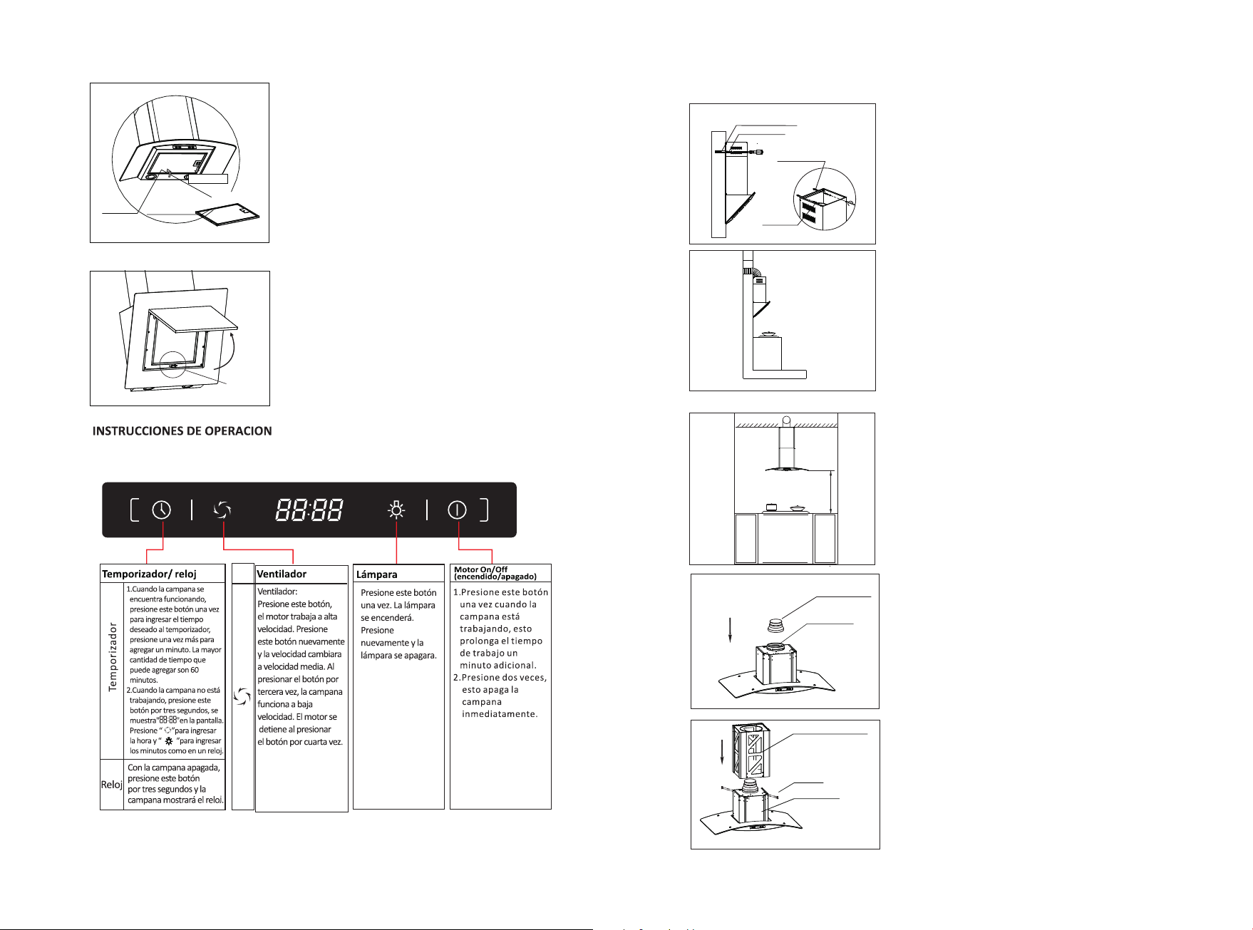
A: Timer
1.When the hood is working, touch this button one time, the hood will
each one more time can add 1 minute, the longest time you can set is 60
minutes.
2.When the hood is non-working, touch this button 3 seconds, you can
use “Lighting”and “Speed”button to set time like a clock,“Lighting”
can set hour, “Speed” can set minute.
B: Lighting
Touch this button one time, the lamp will be lighted; Touch again, the
lamp will extinguish.
C:Speed
Touch this button, the motor works in high speed, touch this button
again, the middle speed runs; touch the button thrice, the low speed
runs; the motor stops after
touching it quartic.
D: On/ Off
This general On/Off button, touch this button first before you touch
other buttons; touch this button when the hood is working, the motor
stops running, lights turn off.
A
B C D
11
5
Paso 5:
Ponga el ducto interno en el ducto externo.
Tenga en cuenta que el ducto interno debe
fijarse de acuerdo a la ranura de orientación.
Ducto interno
Ducto externo
Ranura de
orientación
Paso6:
Ponga el ducto externo en la carcasa de la
unidad. Use dos tornillos M4x10 para fijar
el ducto exterior a la unidad.
Paso 7:
1)Extienda la cubierta interna a la altura
deseada. Marque dos orificios del gancho
del ducto interno en la pared.
2)Ponga la cubierta del ducto interno
suavemente usando una broca de 8 mm
para perforar dos orificios de 60-70 mm de
profundidad en la pared que usted acaba
de marcar.
3)Presione los tubos de expansión dentro de
los orificios
4)Extienda el ducto externo y apriete los dos
tornillos de madera 5x60 dentro de los
tubos de expansión.
Cubierta del ducto interno
Cubierta del ducto externo
Tornillos de fijaci n
para el ducto externo
ó
Tubo de expansi nó
Tornillo de madera
Tubo de expansi nó
Tornillo de madera
Paso 8:
Extienda el tubo de escape al tubo de
ventilación de su edificio o hacia el exterior.
Trate de hacer un doblez del tubo de
ventilación de más de 120°.
Paso 9:
Instale el filtro. Ponga el perno de fijación en
el orificio de fijación y presione el gancho del
filtro suavemente en dirección a la flecha A.
Agujero de
fijaci nó
Perno de fijaci nó
Dirección
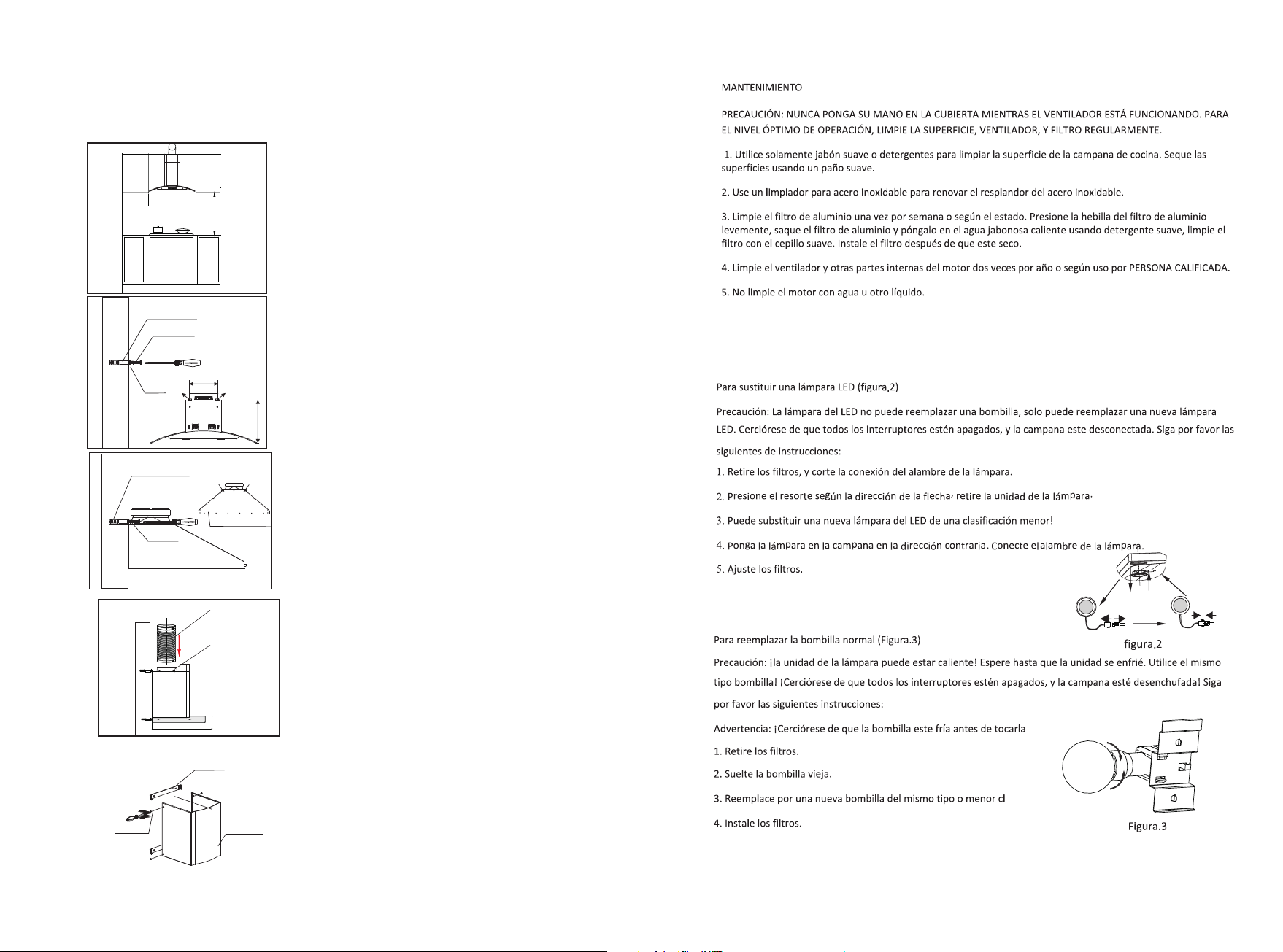
MAINTENANCE
CAUTION: NEVER PUT YOUR HAND INTO THE AREA HOUSING WHILE
THE FAN IS OPERATING.
FOR THE OPTIMAL LEVEL OF OPERATION, CLEAN THE RANGE HOOD
SURFACE, FAN, AND FILTER REGULARLY.
1. Use only mild soap or detergent solutions to clean the cooker hood surface. Dry
surfaces using soft cloth.
2. Using a stainless steel cleaner to bring the glow back into a stainless steel finish.
3. Clean the aluminium filter once a week or according to use status. Press the buckle
of the aluminium filter slightly, take off the aluminium filter and put it into warm soapy
water using mild detergent, wipe the filter with soft brush. Replace the filter after it is dry.
4. Clean the motor fan and other inside parts once half year or according to use by
QUALIFIED PERSON.
5. DO NOT cleaning motor with water or other liquid.
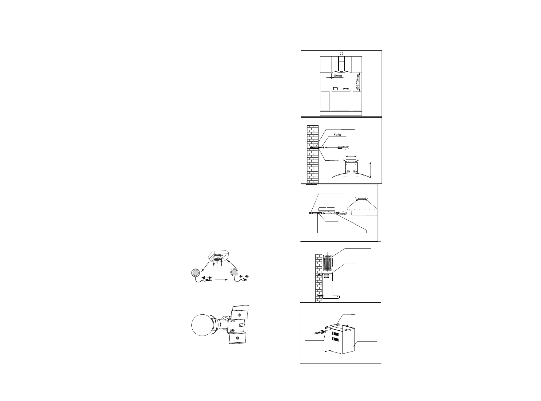
TO REPLACE LAMP
Caution: LED lamp can not replace a new bulb, just can replace a new LED Lamp.
Make sure all the control switches are off, and he cooker hood is unplugged!
Please follow below instructions:
1.Take out the filters, and cut off the wire connection of the lamp.
2.Press the spring according to the arrow direction, then
you can take off the lamp unit.
3.You can replace a new LED lamp unit no more then rating!
4. Then put the lamp unit to the hood in reverse direction. Connect the wire of the lamp.
5. Fit on the filters.
To replace normal lamp bulb(Pic.2)
Caution :lamp unit may be hot! Wait until the unit is cool.
And use the same type light bulb!
Make sure all the control switches are off, and the cooker hood is unplugged! Please follow
below instructions:
Warning: Make sure the bulb is cool before you touch it!
1.Take out the filters.
2.Loose the old light bulb.
3.Replace a new light bulb which is the same type no more
than rating!
4.Fit on the filters.
To replace LEDlamp (Pic.1)
Pic.2
Pic.1
12
4
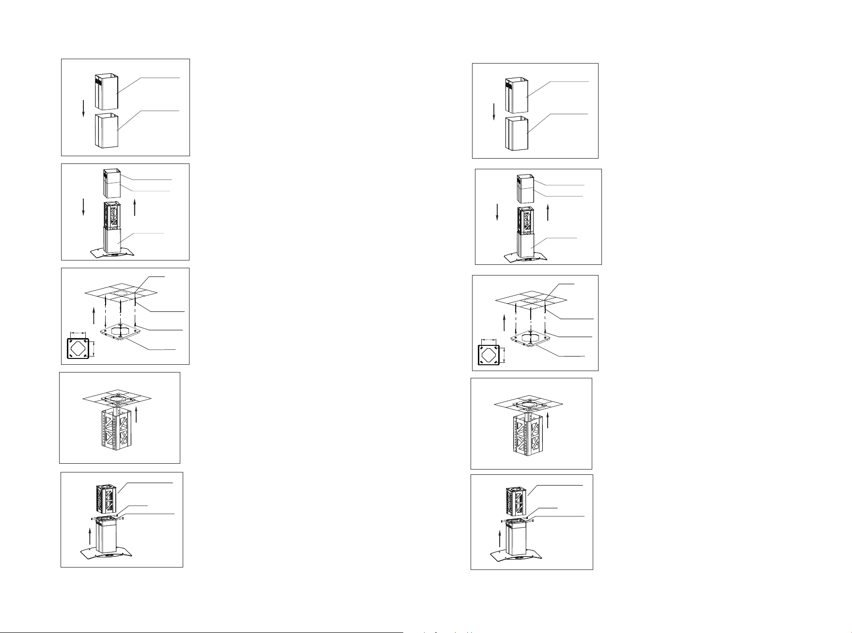
INSTALACION PARA MODELOS PCH760R,PCH762DR,PCH794DR,PCH796DR,
PCH767DR,PCH797DR
Paso 1:
Por favor ponga la campana en la pared y
marque la posición en la que la desea instalar.
Recomendamos que la altura desde la estufa
hasta la parte inferior de la campana debe ser
entre 650 mm hasta 700 mm.
Paso 2:
Marque los cuatro agujeros en la pared de la
forma que aparece en esta figura. Taladre 4
agujeros de 8 mm de diámetro y 60-70 mm de
profundidad en la pared donde usted los
marcó. Presione los 4 tubos de expansión
dentro de los agujeros. Apriete los 4 tornillos
de madera de 5x60 mm que se proveen dentro
de los tubos de expansión. Asegúrese que
estén suficientemente apretados y que no se
puedan mover.
232mm
B
A
Tubo de expansión
Tornillo de madera
Ga n c h o
Paso 3:
Fije el tubo de escape (153 mm diámetro de
lado) al cierre.
Paso 4:
Fije el gancho del ducto interno con los
tornillos M4.
Tubo de escape
Cierre
Soporte
Tornillo M4
Ducto interior
A
B
Expanding Tube
Back of the hood
5x60
Wood Screw
*Fig
It’s advisable to call qualified &authorized Service person for periodically
cleaning the internal assembly;same would be greatly improve the
performance of the products.
Note:-if due to any reason if you don’t use the cooker hood ,oil/fat may
deposed on the filter&surface of the chimney if may start dripping&can cause
the fire also.
Note:- before carrying out the maintence cleaning or replacing the lamp,
disconnect the cooker hood from the main supply(remove the plug from the
socket.)
Re-circulation Mode
Check that activated charcoal filters are fitted properly, so that the impurites
can be effectively absorbed.
The cooker hood better to be operated at the second or lowest speed so that
sufficient time is available for the filtration of the air.The activated charcoal
filters cann’t be re-used&needs periodical change.The life of the activated
charcoal filters are about 3 to 4 months.However if the cooker hood is used
more than 4 hours a day&large amount of oil is used while cooking then
charcoal filter may require more frequent replacement.
*The charcoal filter have to be changed as soon
as they satureated.They can be eaily replaced
by turning them anti clockwise for removing
&clockwise to fefit them .Fig.
Ducting Mode
No need install charcoal filter,exhaust outside.
If you side can exhaust outside,then we suggest
you choose this mode for better performance.
Whatever re-circulation Mode or ducting mode
you choose,Cassette filters need to be cleaned
evey one month.But this may vary on usage
pattern also.In case large amount of oil is used
for cooking ,same has to be cleaned every week
/fortnight. Filters can be easily clean,just put them
in a soap solution of hot water&clean with a brush
&then rinse under a running tap water&wape witha dry cloth.Refix the filters
properly. Instructions for removing &for refit Push the filter lock backward to
release the filter from the slot.
NOTE:Use of optional charcoal filter or ducting mode is left to the installer.
IMPORTANT NOTICE
13
A
3
LEVEL
Fig.4
LEAN
650~700 mm/
350-400 mm
Fig.1 Fig.2 Fig.3
Nivelado Inclinado
1. No instale la campana extractora donde haya muchas puertas o ventanas,
esto es debido para evitar afectar la eficacia del extractor causada por el flujo
de aire(Fig. 1).
2. Instale la campana correctamente encima del tope de cocina. La distancia
recomendada entre el tope y el borde más bajo de la campana para modelos
PCH760R,PCH762DR,PCH794DR,PCH796DR,PCH767DR,PCH797DR,PCH896IR
es de 650mm a 700 mm (Fig. 2). La distancia
recomendada entre el tope y el borde más bajo de la campana para modelos
PCH990R,PCH960R es de 350mm a 400mm (Fig. 2).
3. Para un funcionamiento optimo, no alargue el tubo de escape demasiado,
por lo que intente doblar el tubo de escape menos y el más grande para lograr
que la conexión sea hermética (Fig. 3).
4. Después de colgar la unidad en la pared, asegúrese que la campana este
vertical y nivelada.
5. El ducto de aire no se debe conectar a los tubos de la chimenea o los
conductos del gas de combustión. El ducto de aire no se debe conectar bajo
ninguna circunstancia a los conductos de ventilación para una habitación en el
cual exista algún aparato de combustión.
6. La campana puede ser instalada de cualquier manera, ya sea modo
recirculación o de duccion. Todos los modelos fueron recientemente instalados
con filtros de carbón en modo recirculación. Si usted quiere modo duccion,
entonces quite los filtros de carbón.
Requisitos de instalación
Manual
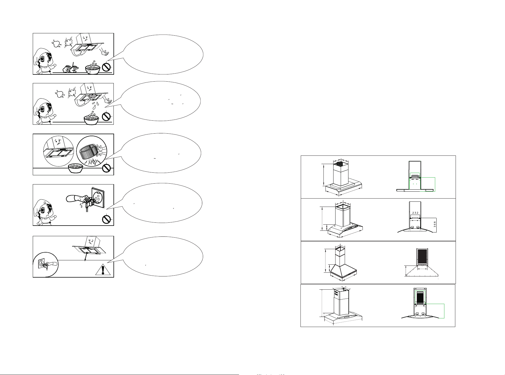
Do clean the hood
correctly in accordance
with instruction stated or it
might cause the possibility
of fire accident
To replace the bulb
should be undertaken by a
qualified electrician or a
competent person. Always
use the bulb no more
than rating.
IMPORTANT SAFETY INSTRUCTIONS:
In case of any
damage to power cable,
replace the broken cable with
a new one by qualified person.
Do not connect the air
outlet to chimney flues or
combustion gas ducts.
Do not leave naked
flames under this hood
14
2
PCH797DR 688/GS14
895
480
500-880
300
283
341
232
A
B
A
B
PCH796DR
300
283
525-920
115
475
895
59 5 / 8 9 5
Ducto telescopico interno
Ducto telescopico externo
Filtro de aluminio
Tubo de escape
Cubierta inferior
Soporte del ducto
Salida de aire
Dress the protective
glove before you start to
clean the hood. Remove the
components gently during
carrying out the
clearance.
Never wash the
control switch with water
or other kind of liquid to avoid
the liquid might cause
electrical problem to
the hood.
To clean the motor
fan should be undertaken
by a qualified person, pay top
attention to avoid any distortion
of the fan during carrying
out the clearance.
Never pull the plug
out of the power supply by
wet hand to avoid the
possibility of electric
shock.
Disconnect the
cooker hood from the
power supply if this appliance
will not be used for
a long time.
Glove
15
1
PCH760R 63160不带 方边1 50风 机
597
487
189
530- 920
186
213
200
180
A
B
PCH762DR 6 6 8S ( 6 0)/ G S 14
295
285
509-900
59
475
595
PCH794DR
30
0
283
895
480
500- 880
PCH767DR 688(60)/GS14
595
480
48
483-873
283
300
A
B
232
339
341
232
A
B
A
B
PCH767DR
PCH797DR
PCH990R
158W
PCH896IR
STATUS
CAUSE AND METHOD OF REPAIRING
The power
supply is
damaged
If the power supply is damaged,please call
technicians to repair.
the
The motor does
not run
a) The motor was broken, replace a new motor
assembly.
b) The switch control was broken, replace a new
switch control.
c) The capacitance was broken, replace a new
capacitance.
a) The installation is not firm enough. Check it and
make sure the hood is firm enough.
b)The fan is broken, so it is not balance. Replace a
new motor assembly.
c) The motor does not firm enough. Check it and
install it firmly enough.
a) Some other things drop to the blower. Check and
clean it.
a) The distance from the cooker hood to the gas
cooker is too big. Make sure the distance is about
650-700mm.
b) There are many windows or doors in the kitchen,
the air convection is too big. Close some doors or
windows, smaller the air convection.
c) There have some other pour wind to the exhaust
pipe. Make the exhaust pipe’s exit to downwards.
d) The run rate of motor decrease obviously. Replace
a new motor or capacitance. Because of the cooker
hood is set upon the window, the best solution is
that put one threeply board on the back of the
cooker hood for covering the hollow of window.
Bulb does not
work
Replace with a new LED lamp assembly.
TOOL
"+" type
Screwdriver
Sharp Pincers
"+" type
Screwdriver
"+" type
Screwdriver
"+" type
Screwdriver
"+" type
Screwdriver
"+" type
Screwdriver
The unit body
shake
Big noise
Suction not so
powerful
TROUBLE SHOOTINGS
CAUTION: Disconnect the power supply before servicing.
16
9-1 0-11
12
12
14 - 15
16
1
1-2
2
3
4- 5 -6-7 -8
Nota Importante
13