
Loading ...
Loading ...
Loading ...
3
ASSEMBLY
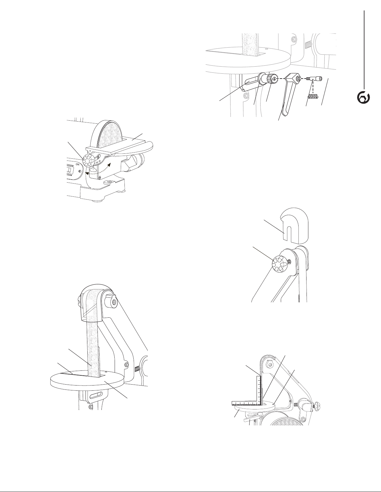
To adjust sanding disc table
• Place a square on the table with the ruler side against
the sanding disc. The table should be 90° to the
sanding disc.
• If the table is not 90° to the sanding disc, loosen the
locking knobs and tilt table up and down until it is 90°
to the sanding disc. Tighten locking knobs securely.
Recheck adjustment using the square.
• For bevel sanding, loosen the locking knobs and tilt
table up and down between 0 –45° to desired angle.
Figure 4
Sanding
Disc Table
Locking
Knob
ASSEMBLE THE SANDING BELT TABLE
Refer to Figure 5–9
• Use the 4 mm hex wrench supplied to disassemble the
locking lever assembly. (bolt, spring, lever and shaft,
see Figure 6).
• Pass the sanding belt/backstop through the slot of the
sanding belt table and position the table as shown.
Figure 5
Sanding
Belt
Sanding Belt Table
Slot
• Use the washer and shaft from the locking lever
assembly to secure the sanding belt table to the frame.
The shaft should be placed at the rear of the adjusting
slot as shown in Figure 6.
• Reassemble the screw, spring and lever to the shaft.
Tighten the locking lever fully to lock the table.
Figure 6
Adjusting
Slot
Shaft
ScrewSpring
Lever
Washer
To adjust sanding belt table:
To square
• If using the backstop, make sure it just touches
the back of the belt. If adjustment is needed, see
Backstop paragraph.
• Remove the upper guard, loosen the lock knob and
slide the guard up and off the belt. See Figure 7.
Figure 7
Belt Guard
Lock Knob
Upper Belt
Guard
• Place a square on the table against the belt as shown.
• Loosen the locking lever assembly and adjust
until square.
• Retighten the locking lever.
Figure 8
567 4 3 2 1
21 3 4 5 67
Leveling Screw
Sanding
Belt
Table
Locking
Lever
Backstop
Sanding Belt
Loading ...
Loading ...
Loading ...