Loading ...
Loading ...
Loading ...
ALIGN TABLE
Refer to Figure 9.
• The table must be aligned properly so that the blade
is at a right angle to the table and that the rip fence
is aligned with the blade.
• Lock the table in the horizontal position. Mount the
rip fence on the table. Slide the rip fence next to, but
not touching, the blade. Lock the rip fence.
• Check that the blade is aligned parallel with the rip
fence. If the blade and fence are not parallel, loosen
the four hex head bolts (Key No. 3) that secure the
upper trunnion to the table. Adjust the table position so
that the blade and rip fence are parallel. Secure the
table position by tightening the four hex head bolts.
• After assembly, the table has to be aligned in order
to have the blade running through the center of the
slot in the table insert.
• To move table sideways, loosen the four hex nuts
(Key No. 14) on the lower trunnion. Move table to left
or right until blade runs through the center of slot.
Tighten hex nuts and make sure that table stays in
position while nuts are being tightened.
ATTACH HANDWHEEL
Refer to Figure 7.
Slide handwheel (Key No. 23) onto threaded shaft (Key
No. 22). Secure handwheel by tightening set screw (Key
No.6).
MOUNT MOTOR
Refer to Figure 6.
• Mount motor to motor mount plate (Key No. 9) using
carriage bolts, lock washers, and hex nuts provided
(Key Nos. 19, 21 and 22).
• Finger tighten hex nuts. Motor will need to be reposi-
tioned to obtain proper V-belt tension.
WIRE MOTOR
Refer to Figures 2 and 6.
The motor should be wired for 115 volts and counter-
clockwise rotation as viewed from shaft end of motor. A
schematic supplied with motor will describe proper
wiring procedures. Be sure to wire motor for counter-
clockwise rotation facing shaft end.
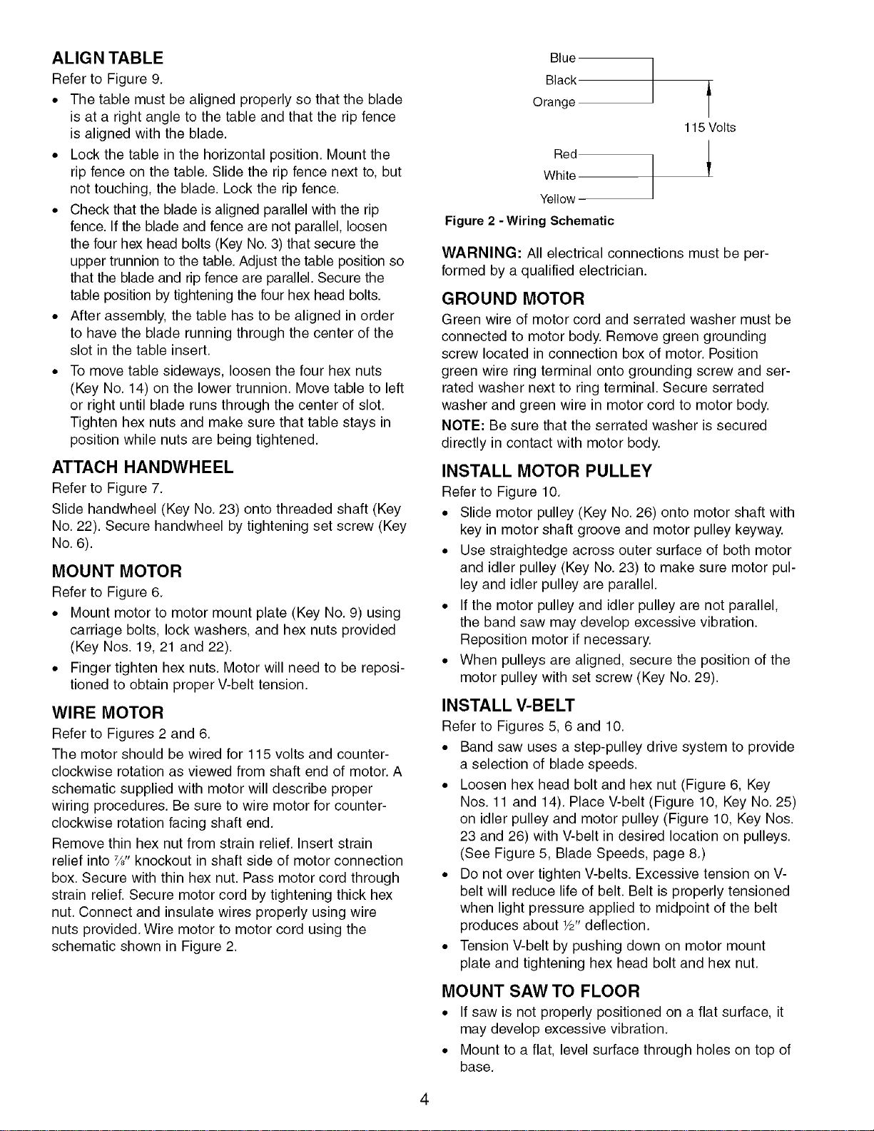
Remove thin hex nut from strain relief. Insert strain
relief into Ys"knockout in shaft side of motor connection
box. Secure with thin hex nut. Pass motor cord through
strain relief. Secure motor cord by tightening thick hex
nut. Connect and insulate wires properly using wire
nuts provided. Wire motor to motor cord using the
schematic shown in Figure 2.
Blue
Black
Orange
Red
White
Yellow
Figure 2 -Wiring Schematic
f
115 Volts
WARNING: All electrical connections must be per-
formed by a qualified electrician.
GROUND MOTOR
Green wire of motor cord and serrated washer must be
connected to motor body. Remove green grounding
screw located in connection box of motor. Position
green wire ring terminal onto grounding screw and ser-
rated washer next to ring terminal. Secure serrated
washer and green wire in motor cord to motor body.
NOTE: Be sure that the serrated washer is secured
directly in contact with motor body.
INSTALL MOTOR PULLEY
Refer to Figure 10.
• Slide motor pulley (Key No. 26) onto motor shaft with
key in motor shaft groove and motor pulley keyway.
• Use straightedge across outer surface of both motor
and idler pulley (Key No. 23) to make sure motor pul-
ley and idler pulley are parallel.
• If the motor pulley and idler pulley are not parallel,
the band saw may develop excessive vibration.
Reposition motor if necessary.
• When pulleys are aligned, secure the position of the
motor pulley with set screw (Key No. 29).
INSTALL V-BELT
Refer to Figures 5, 6 and 10.
• Band saw uses a step-pulley drive system to provide
a selection of blade speeds.
• Loosen hex head bolt and hex nut (Figure 6, Key
Nos. 11 and 14). Place V-belt (Figure 10, Key No. 25)
on idler pulley and motor pulley (Figure 10, Key Nos.
23 and 26) with V-belt in desired location on pulleys.
(See Figure 5, Blade Speeds, page 8.)
• Do not over tighten V-belts. Excessive tension on V-
belt will reduce life of belt. Belt is properly tensioned
when light pressure applied to midpoint of the belt
produces about W' deflection.
• Tension V-belt by pushing down on motor mount
plate and tightening hex head bolt and hex nut.
MOUNT SAW TO FLOOR
• If saw is not properly positioned on a flat surface, it
may develop excessive vibration.
• Mount to a flat, level surface through holes on top of
base.
4
Loading ...
Loading ...
Loading ...