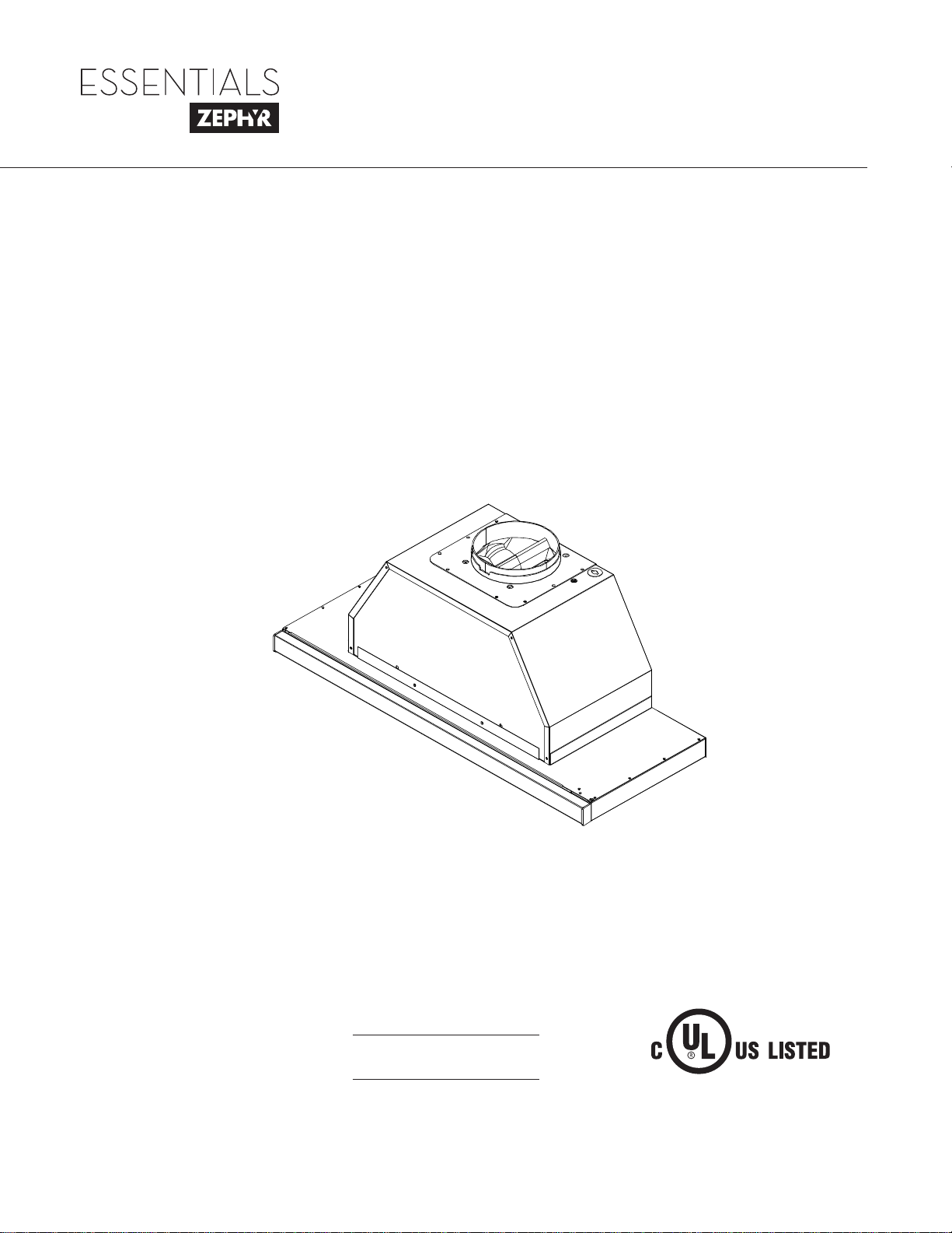
Use, Care, and Installation Guide
www.zephyronline.com
Model number:
Serial Number:
NOV17.0701 © Zephyr Ventilation LLC.
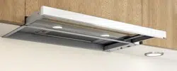
Pisa
ZPI-E24AG
ZPI-E24AG290
ZPI-E30AG
ZPI-E30AG290
ZPI-E36AG
ZPI-E36AG290
ZPI-E24AW
ZPI-E24AW290
ZPI-E30AW
ZPI-E30AW290

www.zephyronline.com

1
SAFETY NOTICE .......................................................................... 2-3
LIST OF MATERIALS
................................................................. 4
INSTALLATION
Ducting Calculation Sheet
....................................... 5
Mounting Height & Clearance
................................ 6
Ducting Options
........................................................... 7
+RRG6SHFL¿FDWLRQV
................................................... 8
Preparing the Cabinet
............................................... 9
Horizontal Ducting Conversion
.............................. 10
Installing the Hood
...................................................... 11 - 13
Recirculation Kit
........................................................... 14
FEATURES & CONTROLS
Slide Controls
................................................................ 15
MAINTENANCE
Hood and Filter Cleaning
......................................... 16
Lights
................................................................................ 17
WIRING DIAGRAMS
................................................................... 18
TROUBLESHOOTING
................................................................ 19
LIST OF PARTS AND ACCESSORIES
.............................. 20
WARRANTY .................................................................................... 21
PRODUCT REGISTRATION
.................................................... 22
Table of Contents

Important Safety Notice
READ AND SAVE THESE INSTRUCTIONS
2
www.zephyronline.com
WARNING
TO REDUCE THE RISK OF FIRE OR ELECTRIC SHOCK, DO NOT USE THIS FAN WITH ANY SOLID-STATE CONTROL DEVICE.
WARNING
TO REDUCE THE RISK OF FIRE ELECTRIC SHOCK, OR INJURY TO PERSONS, OBSERVE THE FOLLOWING:
a. Use this unit only in the manner intended by the manufacturer, if you have questions, contact the manufacturer.
b. Before servicing or cleaning unit, switch power off at service panel and lock panel to prevent power from being switched on accidentally.
When the service disconnecting means cannot be locked, securely fasten a prominent warning device, such as a tag, to the service
panel.
CAUTION
For general ventilating use only. Do not use to exhaust hazardous or explosive materials and vapors. Take care when using cleaning
agents or detergents. Suitable for use in household cooking area.
WARNING
TO REDUCE THE RISK OF RANGE TOP GREASE FIRE:
a. Never leave surface units unattended at high settings. Boilovers cause smoking and greasy spillovers that may ignite. Heat oils slowly
on low or medium settings.
E $OZD\VWXUQKRRG21ZKHQFRRNLQJDWKLJKKHDWRUZKHQÀDPLQJIRRG
F &OHDQYHQWLODWLQJIDQVIUHTXHQWO\*UHDVHVKRXOGQRWEHDOORZHGWRDFFXPXODWHRQIDQRU¿OWHU
d. Use proper pan size. Always use cookware appropriate for the size of the surface element.
H .HHSIDQ¿OWHUVDQGJUHDVHODGHQVXUIDFHVFOHDQ
f. Use high setting on hood only when necessary.
g. Don’t leave hood unattended when cooking.
h. Always use cookware and utensils appropriate for the type of and amount of food being prepared.
WARNING
TO REDUCE THE RISK OF INJURY TO PERSONS IN THE EVENT OF A RANGE TOP FIRE, OBSERVE THE FOLLOWING:
D 6027+(5)/$0(6ZLWKDFORVH¿WWLQJOLGFRRNLHVKHHWRUPHWDOWUD\WKHQWXUQRIIWKHEXUQHU%(&$5()8/7235(9(17%8516
,IWKHÀDPHVGRQRWJRRXWLPPHGLDWHO\(9$&8$7($1'&$//7+(),5('(3$570(17
b. NEVER PICK UP A FLAMING PAN – You may be burned.
c. DO NOT USE WATER, including wet dishcloths or towels – a violent steam explosion will result.
d. Use an extinguisher ONLY if:
1. You know you have a Class ABC extinguisher, and you already know how to operate it.
7KH¿UHLVVPDOODQGFRQWDLQHGLQWKHDUHDZKHUHLWVWDUWHG
7KH¿UHGHSDUWPHQWLVEHLQJFDOOHG
<RXFDQ¿JKWWKH¿UHZLWK\RXUEDFNWRDQH[LW
WARNING
TO REDUCE THE RISK OF FIRE, ELECTRIC SHOCK OR INJURY TO PERSONS, OBSERVE THE FOLLOWING:
D ,QVWDOODWLRQZRUNDQGHOHFWULFDOZLULQJPXVWEHGRQHE\TXDOL¿HGSHUVRQVLQDFFRUGDQFHZLWKDOODSSOLFDEOHFRGHVDQGVWDQGDUGV
,QFOXGLQJ¿UHUDWHGFRQVWUXFWLRQ
E 6XI¿FLHQWDLULVQHHGHGIRUSRZHUFRPEXVWLRQDQGH[KDXVWLQJRIJDVHVWKURXJKWKHÀXHFKLPQH\RIIXHOEXUQLQJHTXLSPHQWWRSUHYHQW
back-drafting. Follow the heating equipment manufacturer’s guideline and safety standards such as those published by the National
)LUH3URWHFWLRQ$VVRFLDWLRQ1)3$DQGWKH$PHULFDQ6RFLHW\IRU+HDWLQJ5HIULJHUDWLRQDQG$LU&RQGLWLRQLQJ(QJLQHHUV$6+5$(DQG
the local code authorities.
c. When cutting or drilling into wall or ceiling, do not damage electrical wiring and other hidden utilities.
d. Ducted fans must always vent to the outdoors.
e. NEVER place a switch where it can be reached from a tub or shower.
f. Make sure the power is off before installing, wiring or maintenancing.

Important Safety Notice
3
WARNING
TO REDUCE THE RISK OF FIRE, USE ONLY METAL DUCTWORK.
CAUTION
7RUHGXFHULVNRI¿UHDQGWRSURSHUO\H[KDXVWDLURXWVLGH'RQRWYHQWH[KDXVWDLULQWRVSDFHVZLWKLQZDOOVFHLOLQJV
attics, crawl spaces or garages. Hood not intended for installation over an outdoor grill.
OPERATION
$OZD\VOHDYHVDIHW\JULOOHVDQG¿OWHUVLQSODFH:LWKRXWWKHVHFRPSRQHQWVRSHUDWLQJEORZHUVFRXOGFDWFKRQWRKDLU¿QJHUV
and loose clothing.
The manufacturer declines all responsibility in the event of failure to observe the instructions given here for installation,
maintenance and suitable use of the product. The manufacturer further declines all responsibility for injury due to
negligence and the warranty of the unit automatically expires due to improper maintenance.
*NOTE: Please check www.zephyronline.com for revisions before doing any custom work.
ELECTRICAL REQUIREMENTS
Important:
Observe all governing codes and ordinances.
It is the customer’s responsibility:
7RFRQWDFWDTXDOL¿HGHOHFWULFDOLQVWDOOHU
- To assure that the electrical installation is adequate and in conformance with National Electrical Code, ANSI/NFPA 70
latest edition* or CSA standards C22.1-94, Canadian Electrical Code, Part 1 and C22.2 No.0-M91 - latest edition** and
all local codes and ordinances.
,IFRGHVSHUPLWDQGDVHSDUDWHJURXQGZLUHLVXVHGLWLVUHFRPPHQGHGWKDWDTXDOL¿HGHOHFWULFLDQGHWHUPLQHWKDWWKH
ground path is adequate.
Do not ground to a gas pipe.
&KHFNZLWKDTXDOL¿HGHOHFWULFLDQLI\RXDUHQRWVXUHWKHUDQJHKRRGLVSURSHUO\JURXQGHG
Do not have a fuse in the neutral or ground circuit.
*National Fire Protection Association Batterymarch Park, Quincy, Massachusetts 02269
** CSA International 8501 East Pleasant Valley Road, Cleveland, Ohio 44131-5575
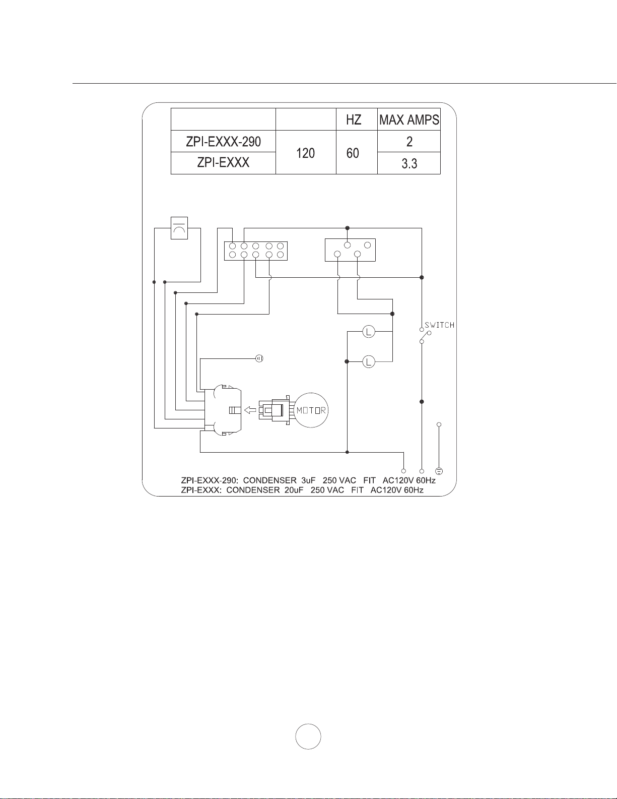
This appliance requires a 120V 60Hz electrical supply and connected to an individual properly grounded branch circuit
protected by a 15 or 20 ampere circuit breaker or time delay fuse. Wiring must be 2 wire with ground. Please also refer to
Electrical Diagram on product.
$FDEOHORFNLQJFRQQHFWRUQRWVXSSOLHGPLJKWDOVREHUHTXLUHGE\ORFDOFRGHV&KHFNZLWKORFDOUHTXLUHPHQWVSXUFKDVH
and install appropriate connector if necessary.
4
www.zephyronline.com
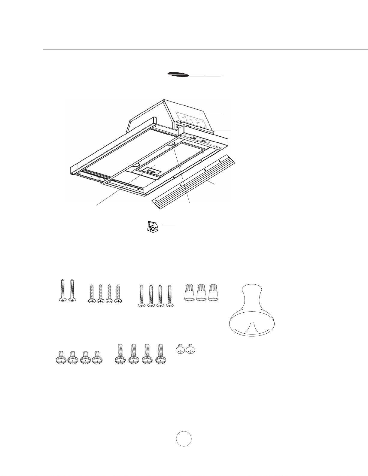
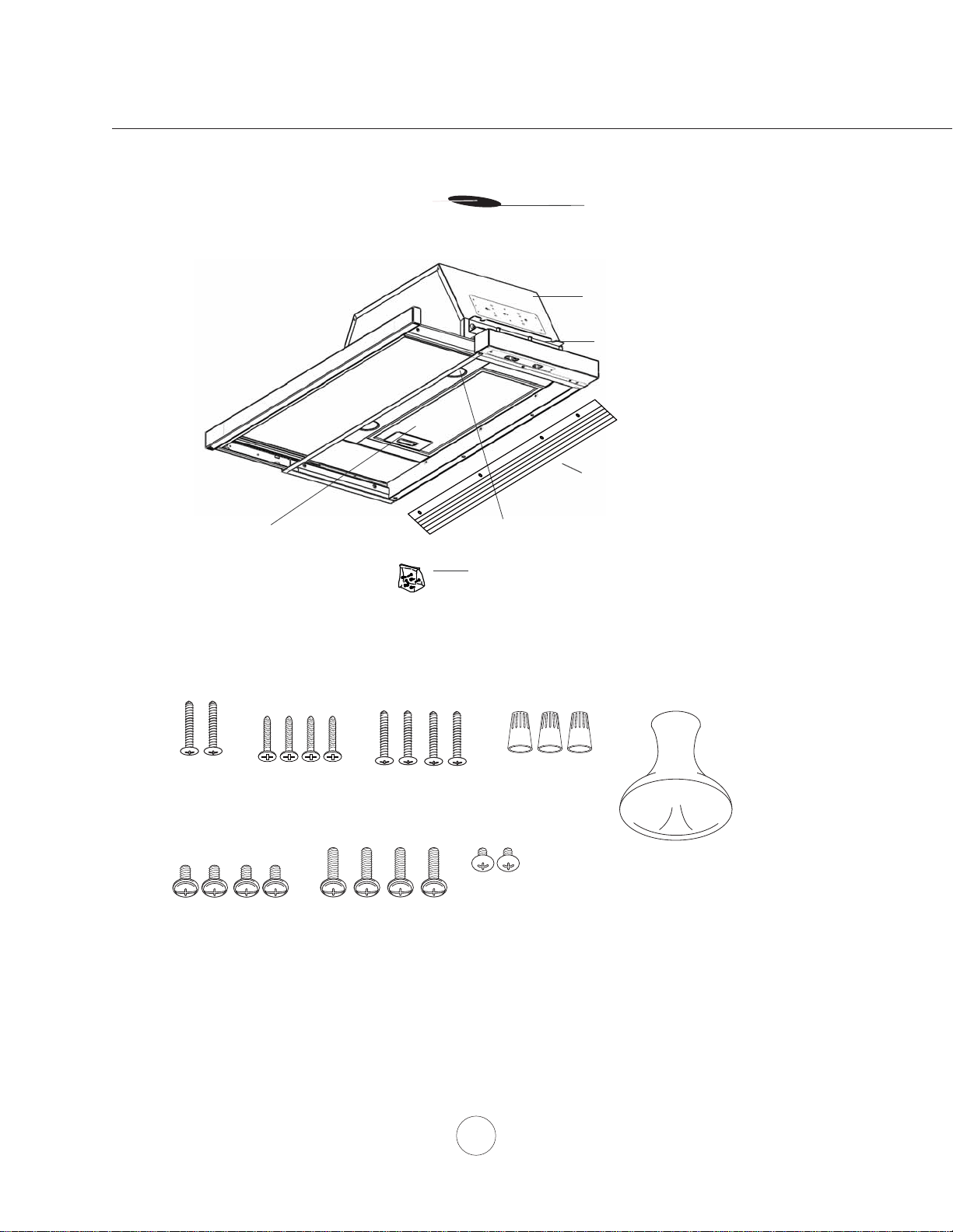
(3) Wire Nuts
(1) Suction Cup
(1) 6” round damper (pre-installed)
(1) hardware package
PARTS SUPPLIED
HARDWARE PACKAGE CONTENTS
PARTS NOT SUPPLIED
- Ducting, conduit and all installation tools
- Cable connector (if required by local codes)
- Recirculation Kit
(2) halogen lights, GU-10 50W
(1) mesh filter
(2) M4 x 1”
(1) hood body with sliding glass
(1) filler panel
(4) M3.5x10
(4) M4 x 16mm
(2) upper installation brackets
(2) lower installation brackets
(24” model only)
(2) M4 x 8
(4) 3/16 x 3/8”
(4) 3/16 x 40
(24” model only)
(24” model only)
(24” model only)
List of Materials
5
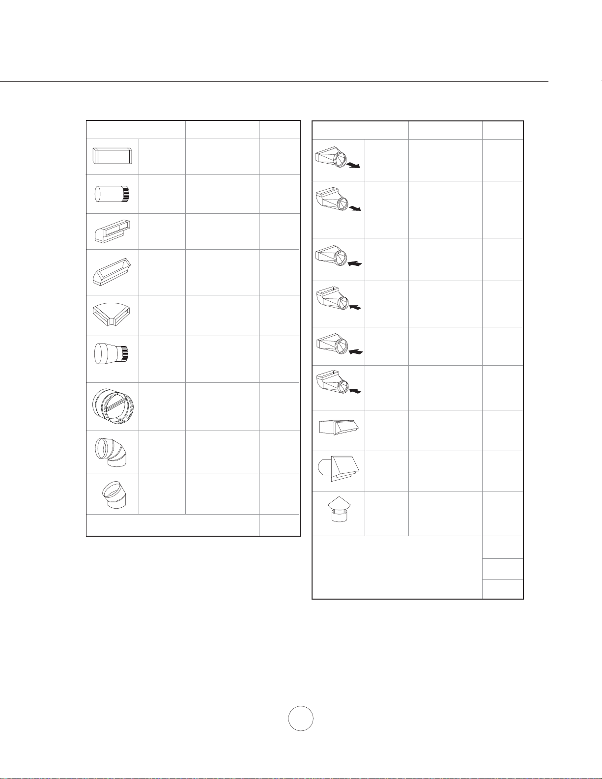
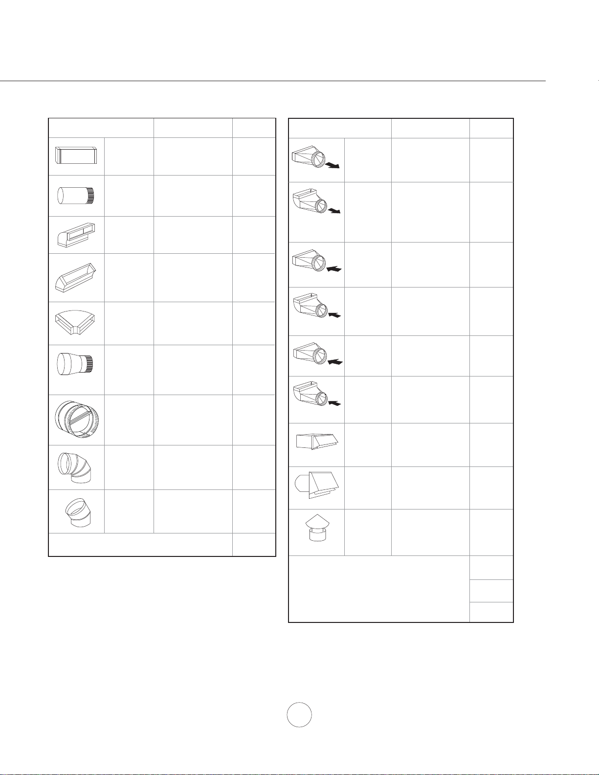
Duct pieces
Tot a l
Equivalent number
length x used =
3- 1/4” x 10”
Rect.,
straight
1 Ft. x ( ) =
Ft.
3- 1/4” x 10”
Rect. to
6” round
transition
5 Ft. x ( ) =
Ft.
3- 1/4” x 10”
Rect. to
6” round
transition
90
0
elbow
20 Ft. x ( ) =
Ft.
6”, 7”, 8”, 10”
Round,
90
0
15 Ft.
x ( ) =
Ft.
6”, 7”, 8”, 10”
Round,
45
0
9 Ft. x ( ) =
Ft.
Ft.
6”, 7”, 8”, 10”
Round,
straight
1 Ft. x ( ) =
Ft.
Subtotal column 1 =
Duct pieces
Tot a l
Equivalent number
length x used =
6”, 7”, 8”, 10”
Round, wall
cap with
damper
30 Ft. x ( ) =
Ft.
Ft.
Ft.
Ft.
6”, 7”, 8”, 10”
Round
roof cap
30 Ft. x ( ) =
Ft.
Subtotal column 2 =
Subtotal column 1 =
Total ductwork =
Maximum Duct Length: For satisfactory air movement,
the total duct length
should not exceed 100 equivalent feet.
6” round to
3- 1/4” x 10”
rect.
transition
1 Ft. x ( ) =
Ft.
6” round to
3- 1/4” x 10”
rect.
transition
90
0
elbow
16 Ft. x ( ) =
Ft.
7” round to
3 1/4” x 10”
rect.
transition
8 Ft. x ( ) =
Ft.
7” round to
3- 1/4” x 10”
rect.
transition
90
0
elbow
23 Ft. x ( ) =
Ft.
elbow
elbow
7” to 6” or
8” to 7” Round
tapered
reducer
25 Ft. x ( ) =
Ft.
3- 1/4” x 10”
Rect. 90
0
elbow
15 Ft. x ( ) =
Ft.
3- 1/4” x 10”
Rect. 45
0
elbow
9 Ft. x ( ) =
Ft.
3- 1/4” x 10”
Rect. 90
0
flat elbow
24 Ft. x ( ) =
Ft.
3- 1/4” x 10”
Rect.
wall cap
with damper
30 Ft. x ( ) =
Ft.
Ft. x ( ) =
Ft.
15
6”, 7“, 8”
Round
in-line
damper
Installation – Ducting Calculation Sheet
6
www.zephyronline.com
DUCTING
A minimum of 6” round ducting must be used to
PDLQWDLQPD[LPXPDLUÀRZHI¿FLHQF\
Always use rigid type metal ducts only. Flexible
GXFWVFRXOGUHVWULFWDLUÀRZE\XSWR
Use calculation worksheet to compute total duct
work.
ALWAYS, when possible, reduce the number of
transitions and turns. If a long duct run is required,
increase duct size from 6” to 7” or 8”.
If turns or transitions are required: Install as far
away from opening and as far apart, between 2,
as possible.
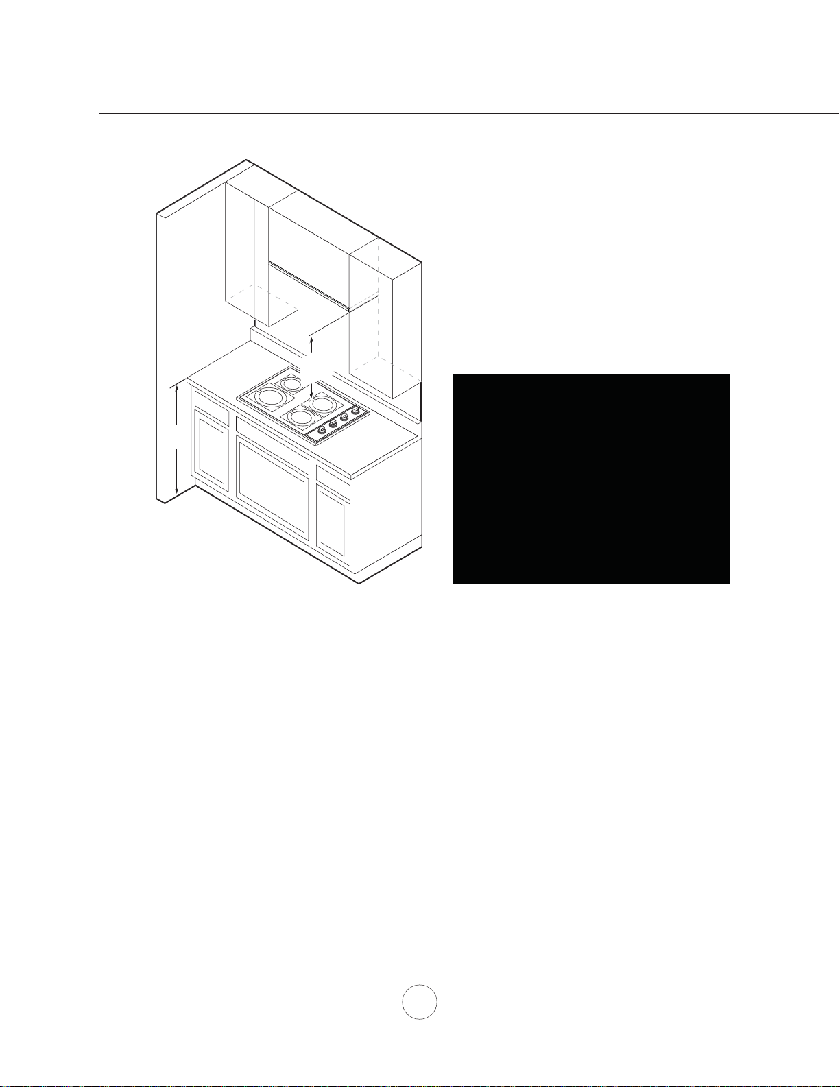
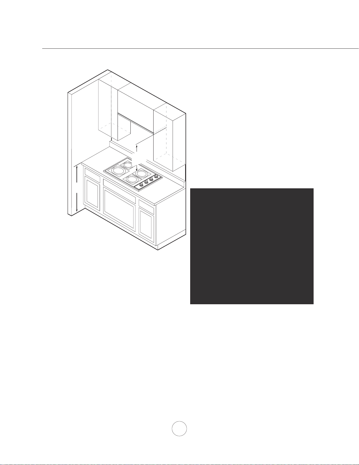
36”
24” min.
32” max.
Mounting height from top of cooking surface to
bottom of hood should be no less than 24” and no
more than 32”.
It is important to install the hood at the proper
mounting height. Hoods mounted too low could
UHVXOWLQKHDWGDPDJHDQG¿UHKD]DUGZKLOHKRRGV
mounted too high will be hard to reach and will
ORVHSHUIRUPDQFHDQGHI¿FLHQF\
If available, also refer to range manufacturer’s
height clearance requirements and recommended
hood mounting height above range. Always check
your local codes for any differences.
DAMAGE-SHIPMENT / INSTALLATION:
3OHDVHIXOO\LQVSHFWXQLWIRUGDPDJHEHIRUH
installation.
,IWKHXQLWLVGDPDJHGLQVKLSPHQWUHWXUQ
the unit to the store in which it was bought
for repair or replacement.
,IWKHXQLWLVGDPDJHGE\WKHFXVWRPHU
repair or replacement is the responsibility
of the customer.
,IWKHXQLWLVGDPDJHGE\WKHLQVWDOOHU
LIRWKHUWKDQWKHFXVWRPHUUHSDLURI
replacement must be made by arrangement
between customer and installer.
Installation – Mounting Height & Clearance
7
WARNING FIRE HAZARD
NEVER exhaust air or terminate duct work into spaces between walls, crawl spaces, ceiling, attics or garages.
All exhaust must be ducted to the outside.
Use single wall rigid Metal ductwork only.
)DVWHQDOOFRQQHFWLRQVZLWKVKHHWPHWDOVFUHZVDQGWDSHDOOMRLQWVZFHUWL¿HG6LOYHU7DSHRU'XFW7DSH
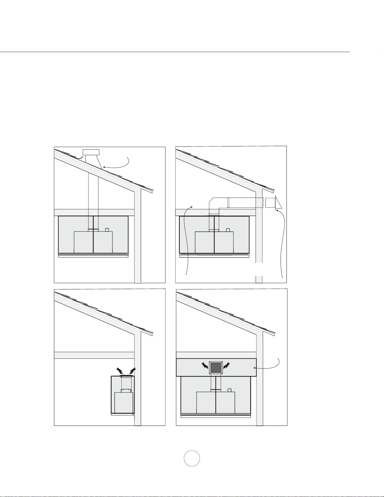
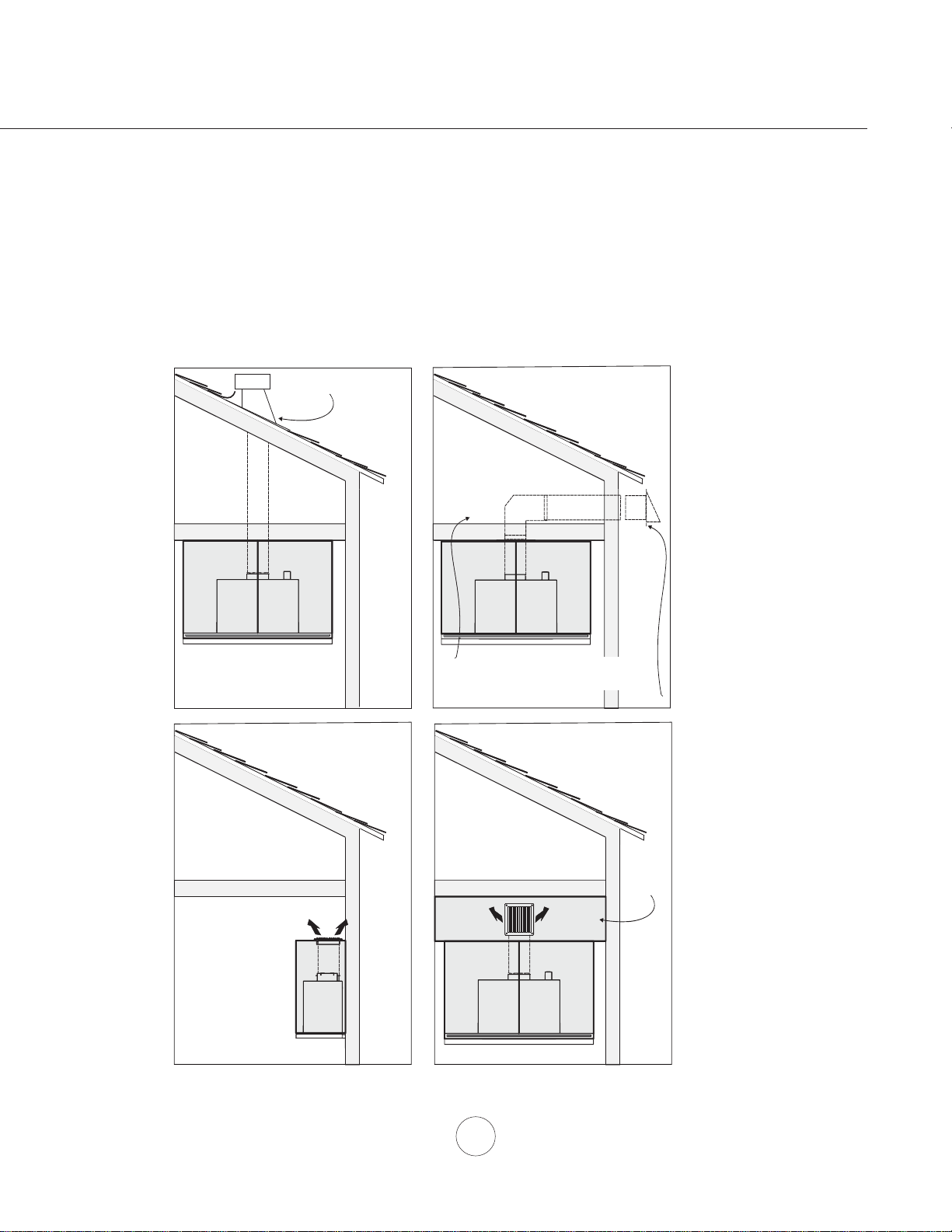
Ducting Options Example
Installation – Ducting Options
soffit or crawl space
roof pitch w/
flashing & cap
ductless
recirculating
w/ gravity damper
side wall cap
ductless
recirculating
soffit

8
www.zephyronline.com
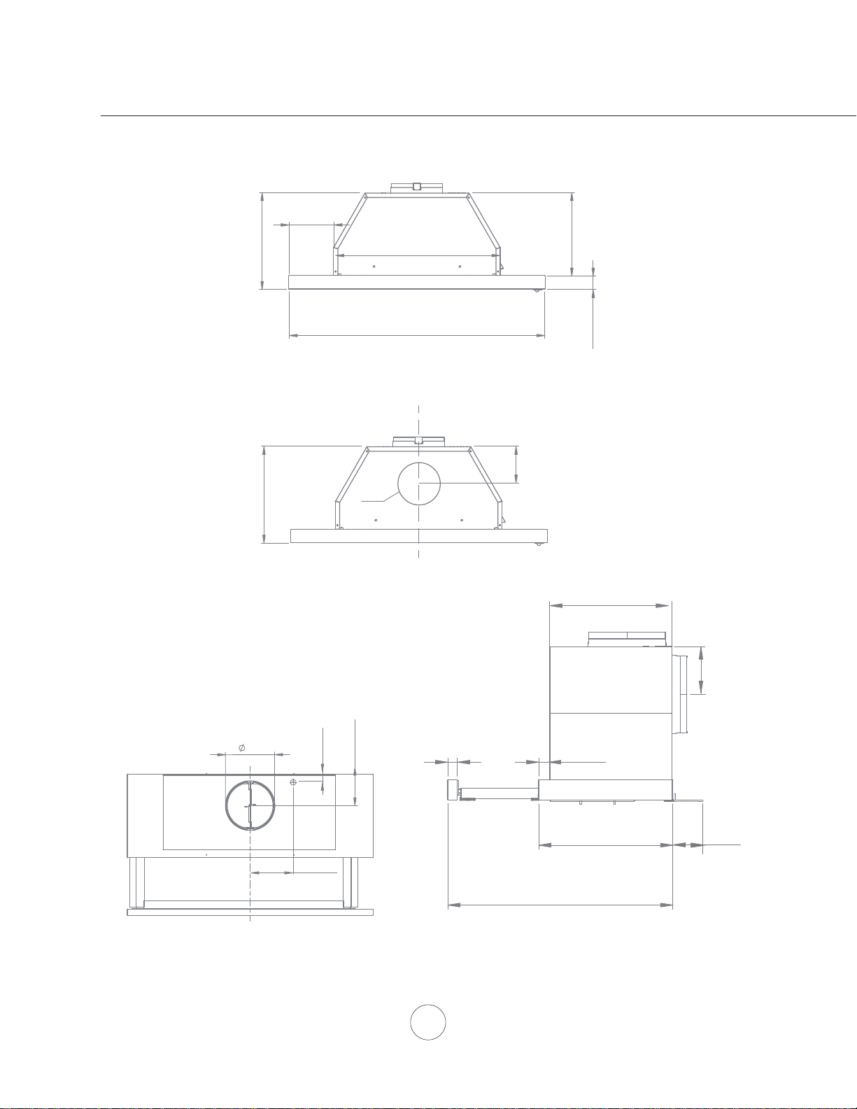
Installation – +RRG6SHFL¿FDWLRQV
TOP
FRONT
SIDE
6
CL
"
3
7/16”
3/4”
23 7/8”(24”), 29 7/8”(30”), 35 7/8”(36”)
19
1
1/2”
9
9/16”
11
1/4”
9/16”
5
3/16” (30”)
11-
15/16
” - 18-
3/4
”
11
1/8”
13/16”
9
7/8
”
1
1/8”
4
/15 16”
closed open
3 7/16”
3/8” -
2 1/4"*
*adjustable rear
filler panel
C/L
3
7/16”
11
1/4”
Ø
6”
BACK
8
3/16” (36”)
11/16”1
2
3/16” (24”)
9
7 3/4”
7”
10-
1/8”
19-
7/8”
C/L
1-
15/16”
*11-
1/2”
*6-
3/16”
7”
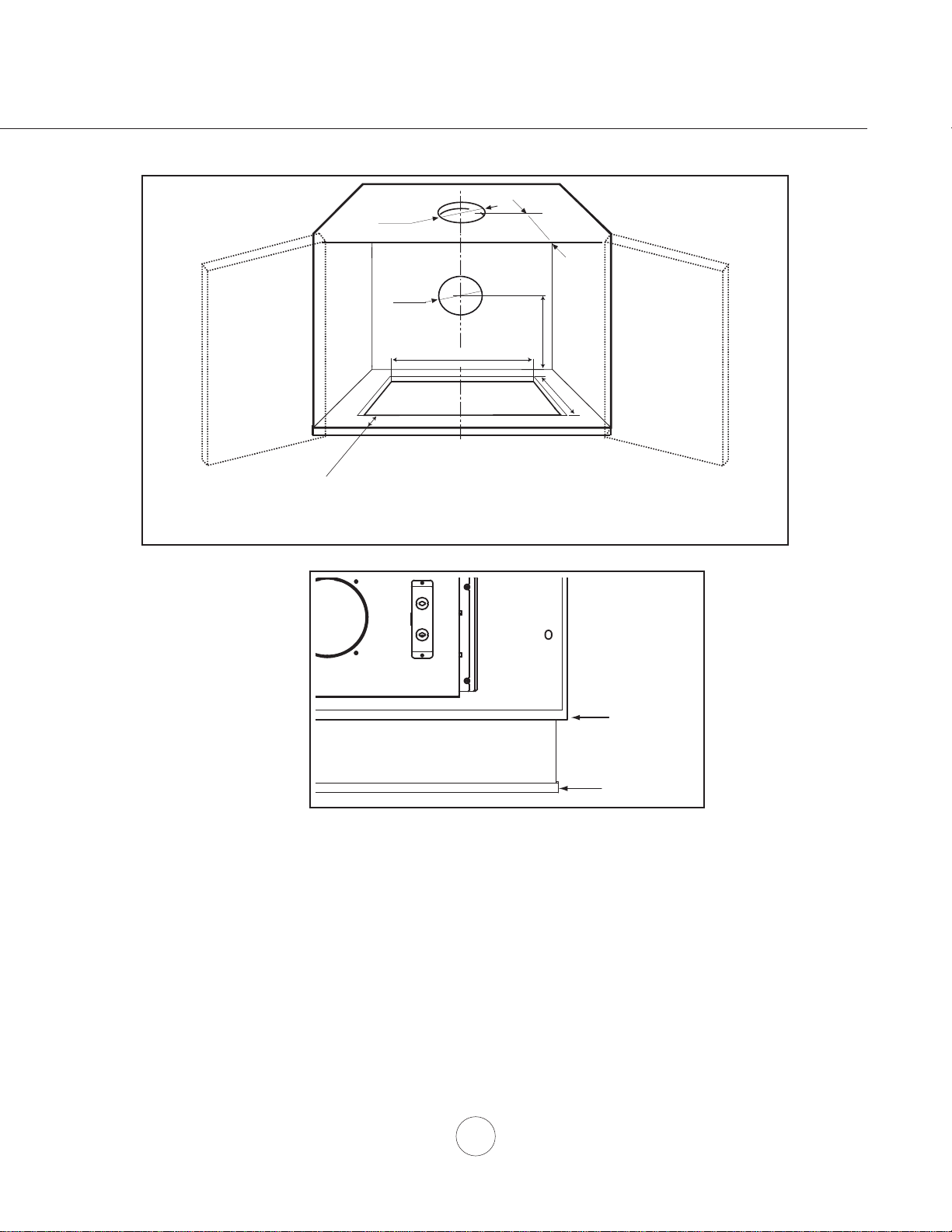
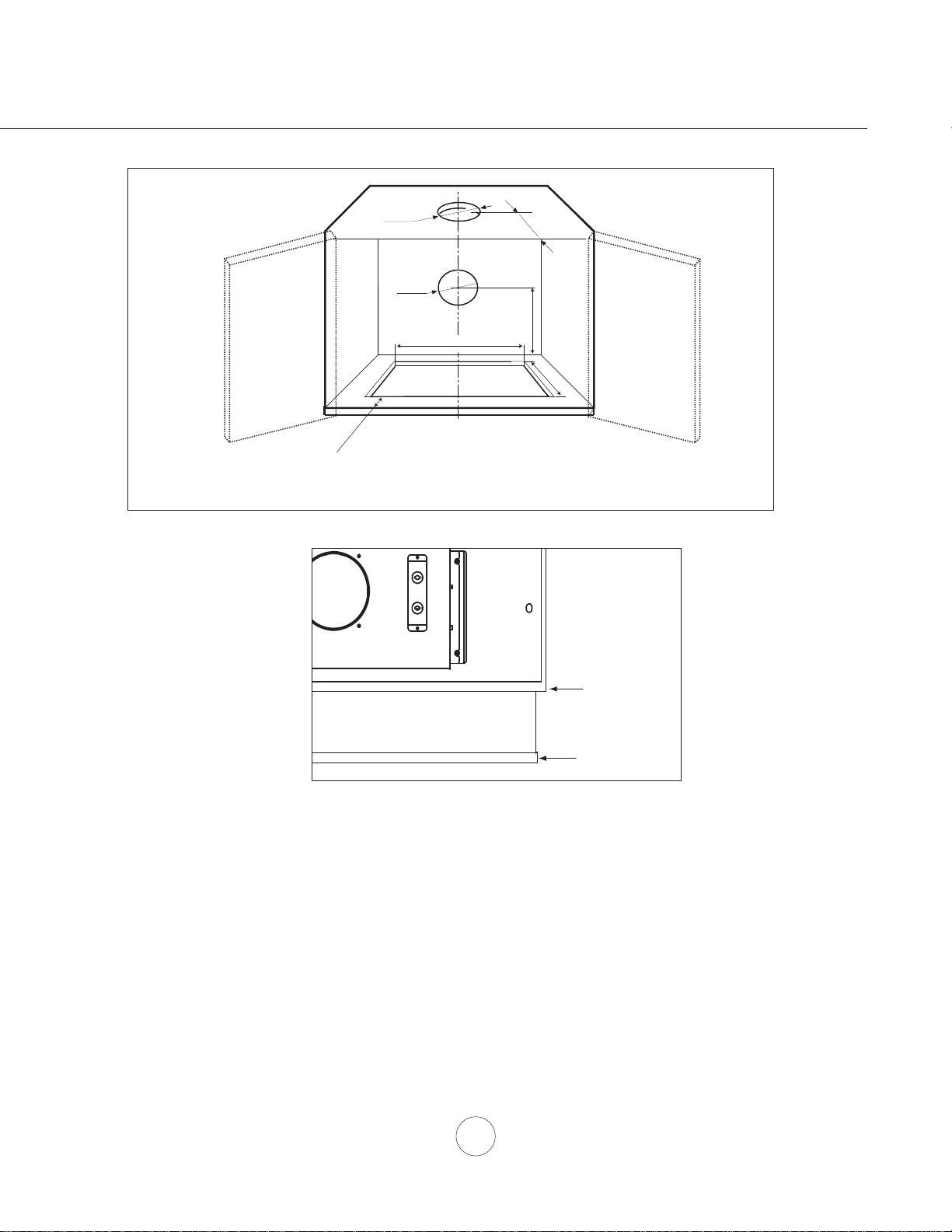
Installation – Preparing the Cabinet
Fig.2
front edge
glass handle
1. Determine and mark center line on wall and cabinet bottom with a pencil.
2. If the cabinet bottom is recessed, wood blocking must be installed to ensure proper
DOLJQPHQWRIWKHKRRGZLWKWKHFDELQHWERWWRP:RRGEORFNLQJVKRXOGEHÀXVK
within cabinet bottom.
3. Follow the dimensions in Fig.1 and cut-out the bottom of your cabinet to create an opening
IRUWKHKRRGWR¿WWKURXJK)RUIUDPHOHVVFDELQHWPHDVXUH´IURPWKHIURQWRI
cabinet door. For framed cabinet measure 1-15/16” from front of cabinet bottom.
Fig.1
* Dimension used for rear ducting option
10
www.zephyronline.com
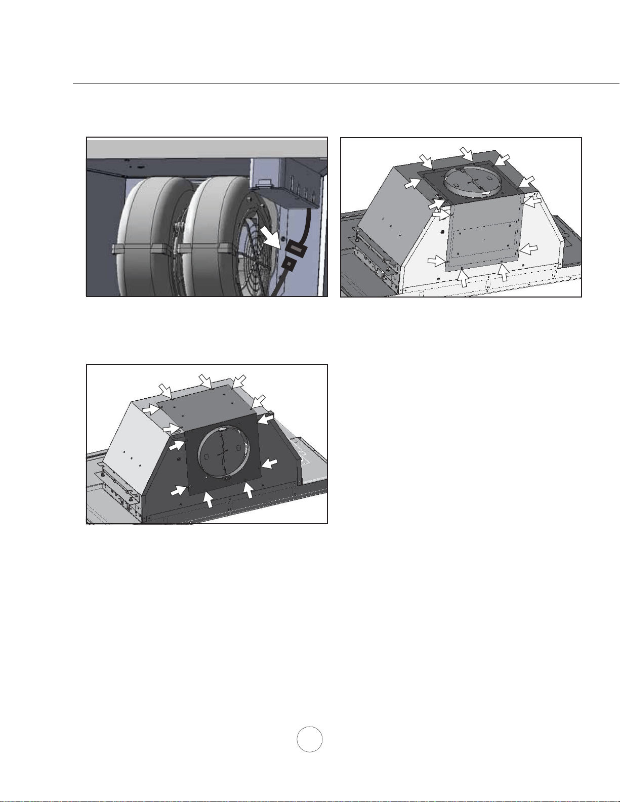
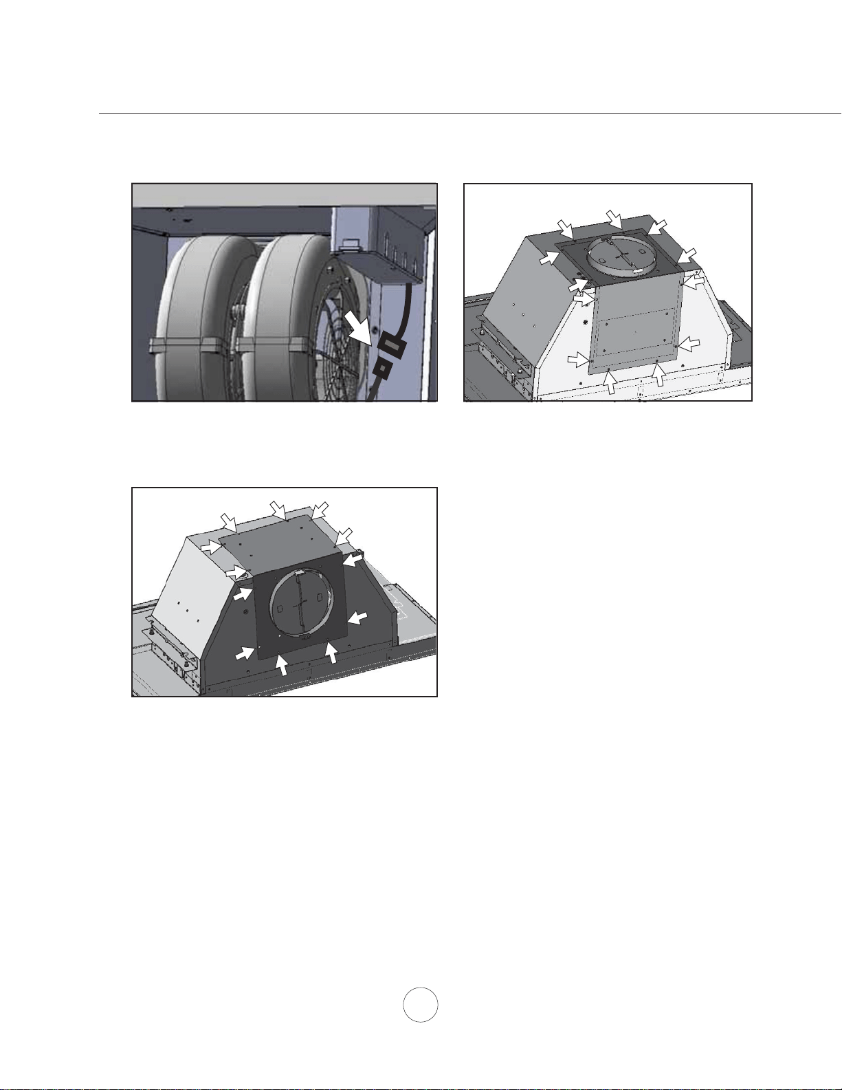
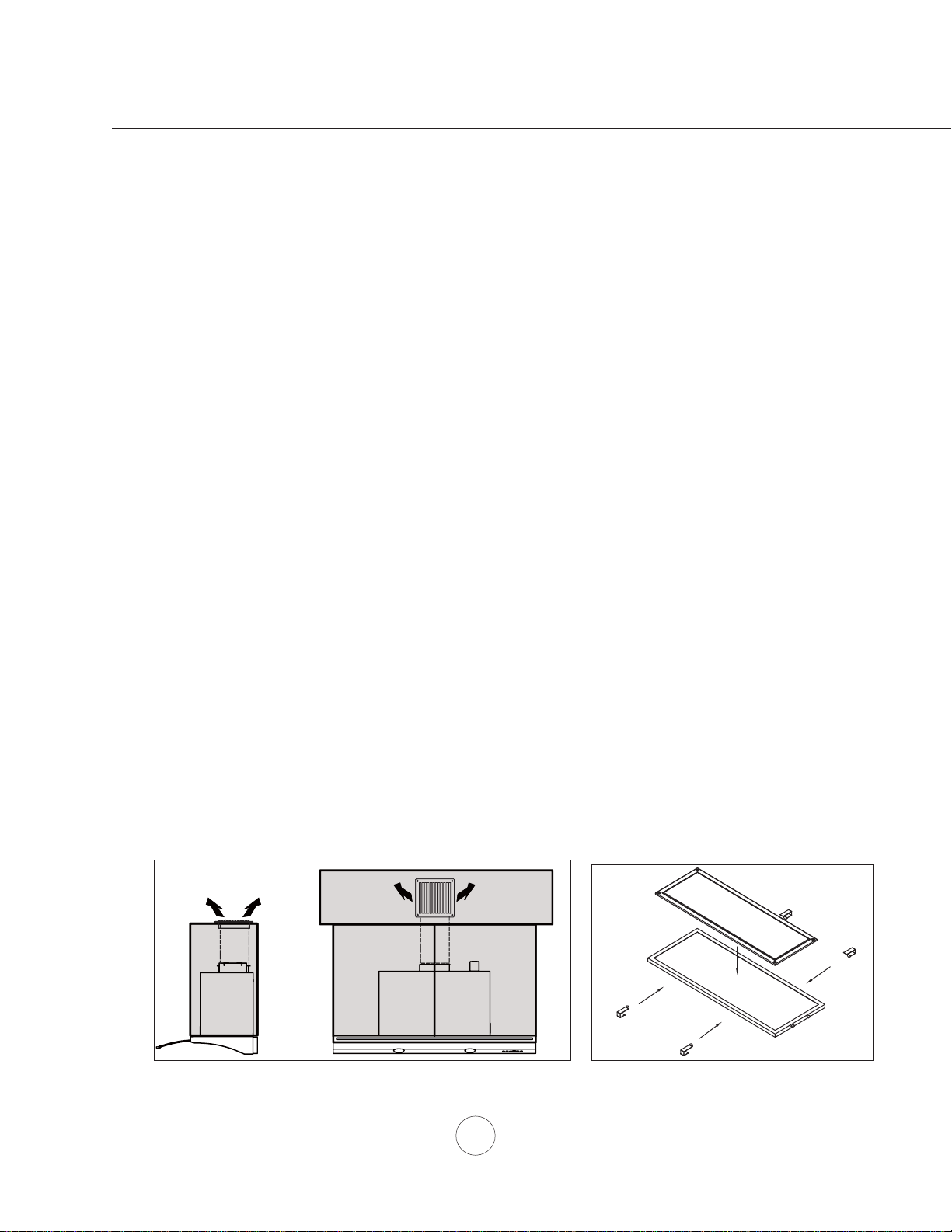
6” ROUND VERTICAL TO HORIZONTAL DUCTING CONVERSION
Installation – Horizontal Conversion
5HPRYHDOXPLQXPPHVK¿OWHU)URPLQVLGHWKHKRRG
disconnect blower plug located toward the right side
interior of hood body.
5HPRYHVFUHZVIURPWRSRIKRRGDQGVFUHZVIURP
back of hood attaching blower plate to hood body.
5HPRYHEORZHUDQGEORZHUSODWHIURPKRRGERG\DQG
reposition blower to hood body so blower collar protrudes
from back of hood body. Re-install blower plate to hood
ERG\XVLQJWKHVFUHZVSUHYLRXVO\UHPRYHGIURPVWHS
Re-connect blower plug.
11
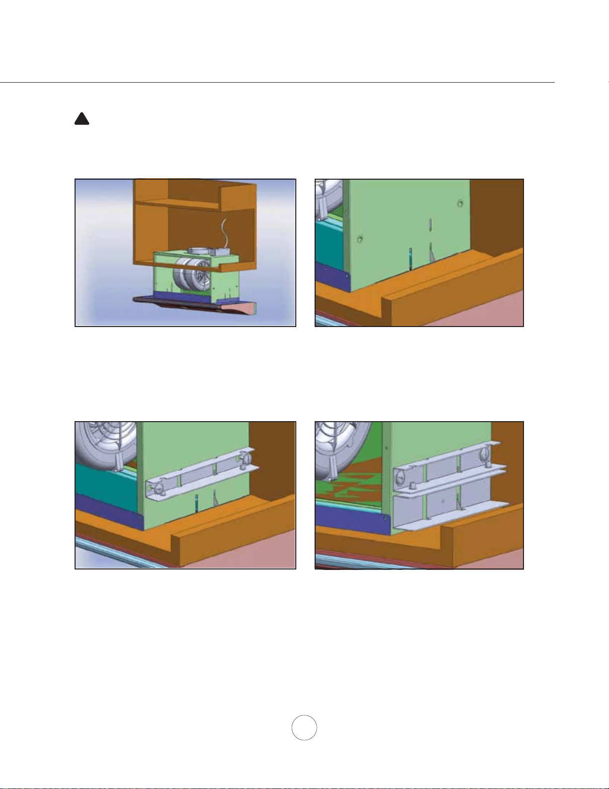
Installation – Installing the Hood
WARNING: Electrical wiring must be done by a qualified person(s) in
accordance with all applicable codes and standards. This range hood must be
properly grounded. Turn off electrical power at service entrance before wiring.
!
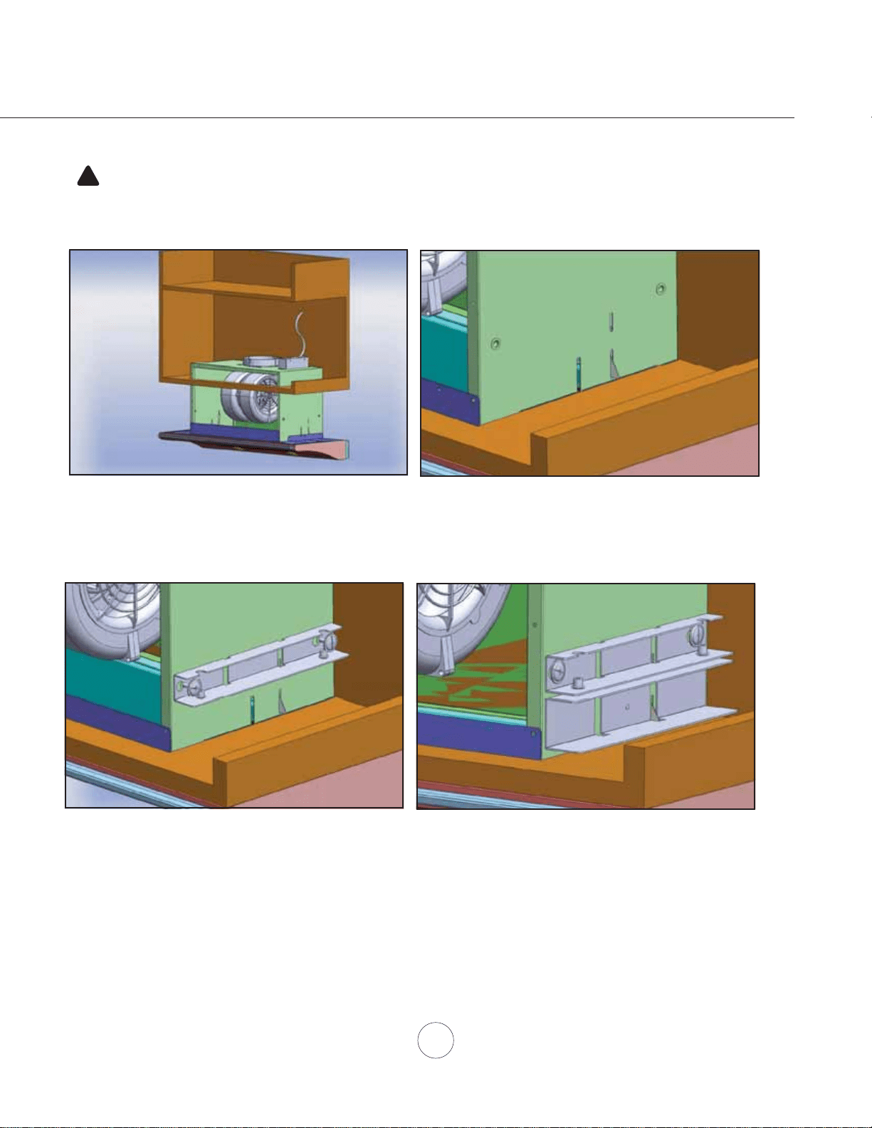
3UHSDUHHOHFWULFDOZLULQJDQGGXFWLQJLQFDELQHW/RFDWLRQRIMXQFWLRQER[DQGEORZHURXWOHWFDQEHIRXQGRQSDJH
Fig.3
2SHQFDELQHWGRRUV/LIWUDQJHKRRGDQGVOLGHLWWKURXJK
the opening located in the bottom of the cabinet, Fig.3.
Make sure opening matches the dimensions on page 9,
Fig.1.
7KHUHDUHVSULQJFOLSVORFDWHGRQWKHOHIWDQGULJKWVLGHV
of the hood body which will temporarily hold the hood in
place, Fig.4.
Fig.4
Fig.5
24” Models Only. Secure upper brackets to left and
ULJKWVLGHVRIKRRGERG\E\XVLQJ[´VFUHZVIRU
HDFKEUDFNHW)LJ0DNHVXUHWKHFDSWLYHQXWVFUHZV
holes on the bracket are facing downward.
24” Models Only. Place lower installation brackets
under upper installation brackets located on left and right
sides of hood body, Fig.6. Note: The wider portion of the
lower installation bracket should be at the bottom.
Fig.6

12
www.zephyronline.com
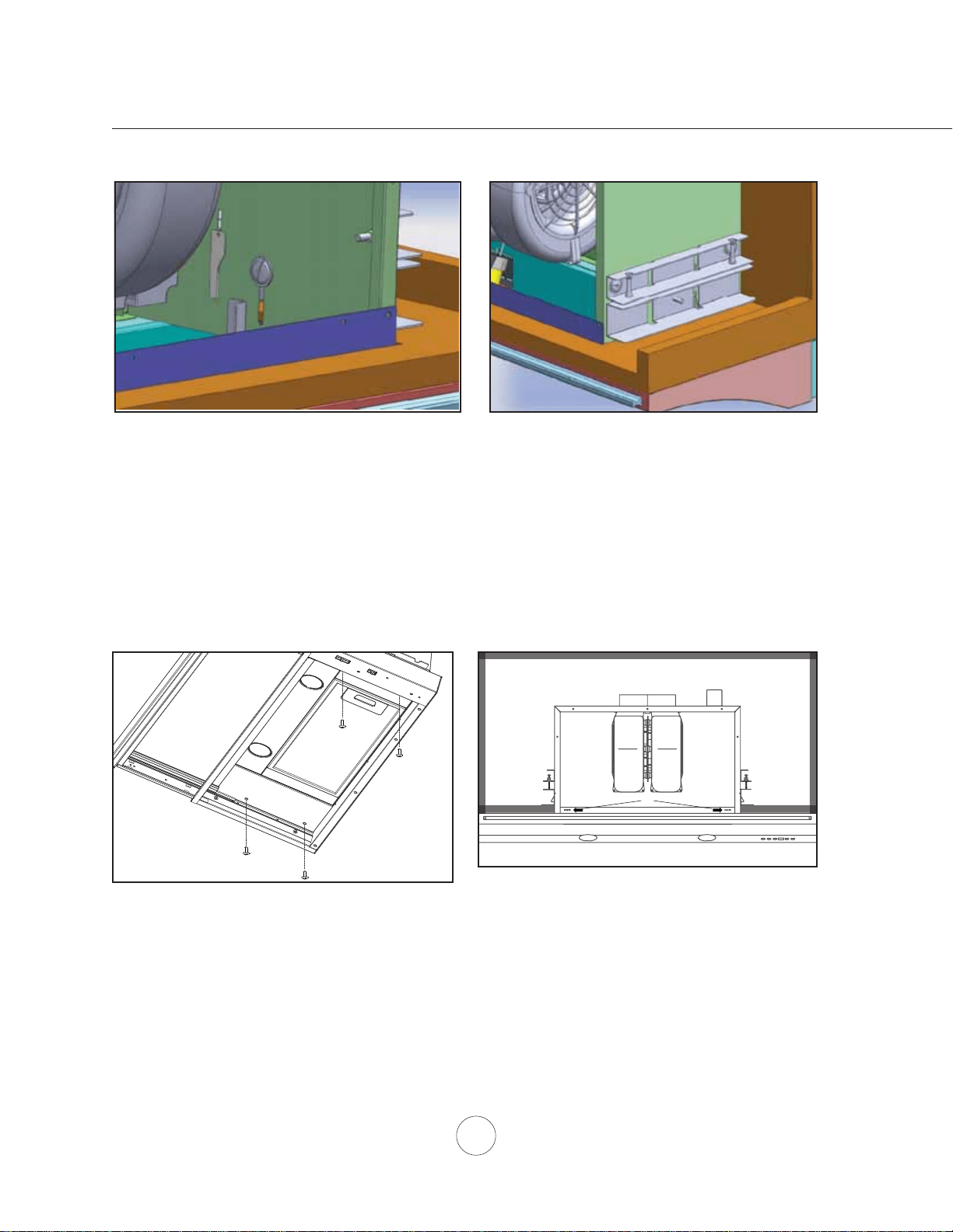
Installation – Installing the Hood
30” & 36” Models Only. Secure hood body to cabinet
EDVHE\0[PPVFUHZVWKURXJKWKHERWWRPRI
range hood.
A
6HFXUH´ZRRGVFUHZV$LQWRWKHVFUHZKROHVRQ
WKHOHIWDQGULJKWVLGHVRIWKH¿OWHURSHQLQJ
Fig.7
24” Models Only)URPLQVLGHWKHKRRGVHFXUH
M4x8 screw into each lower installation bracket. The
position of this screw is adjustable to accomodate various
cabinet bottom thicknesses, Fig.7.
24” Models Only,QVWDOO[VFUHZVLQWRWKH
captive nuts of each upper installation bracket. Tighten
screws to adjust the height of the range hood until there
is no gap between the cabinet and front edge of the hood,
Fig.8.
Fig.8
Installation – Installing the Hood
13
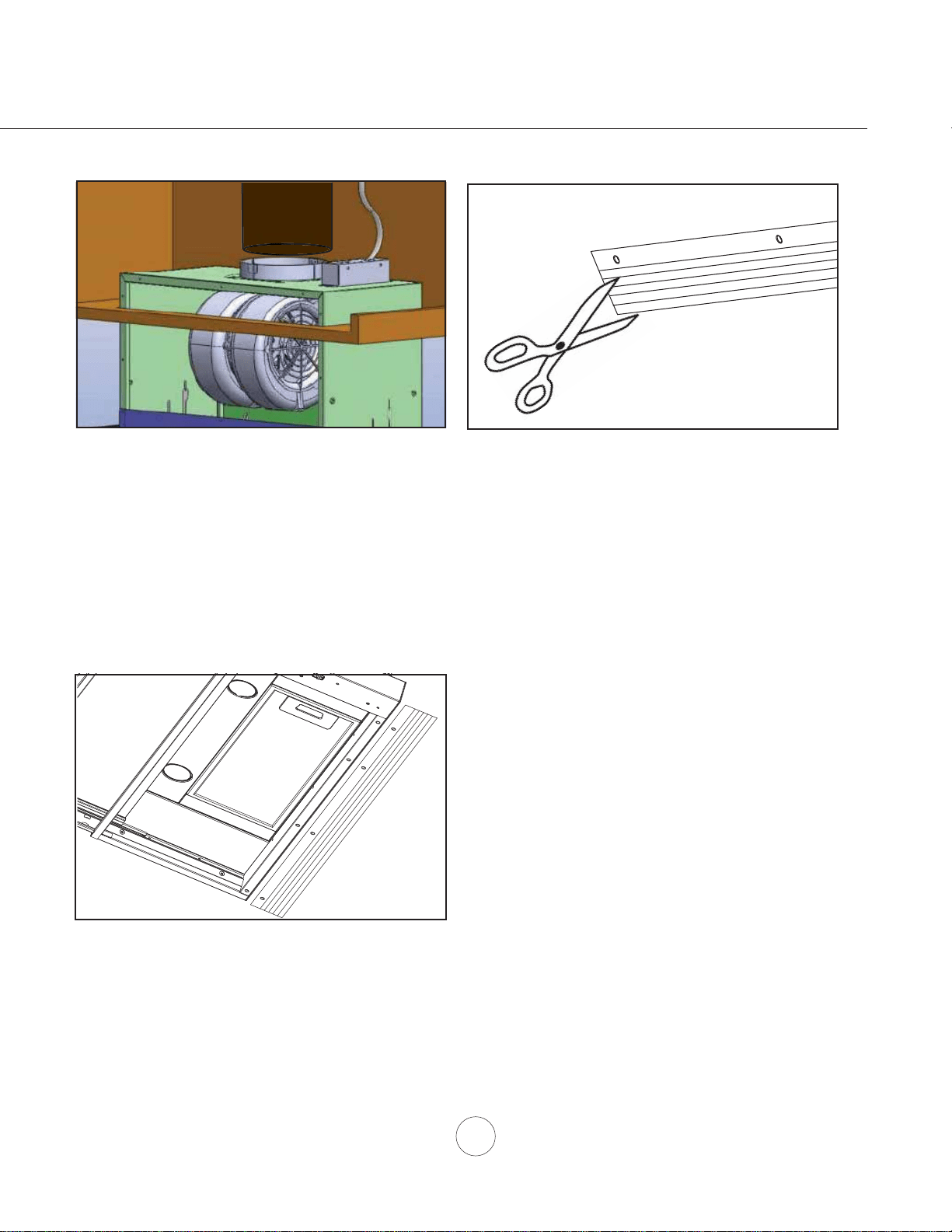
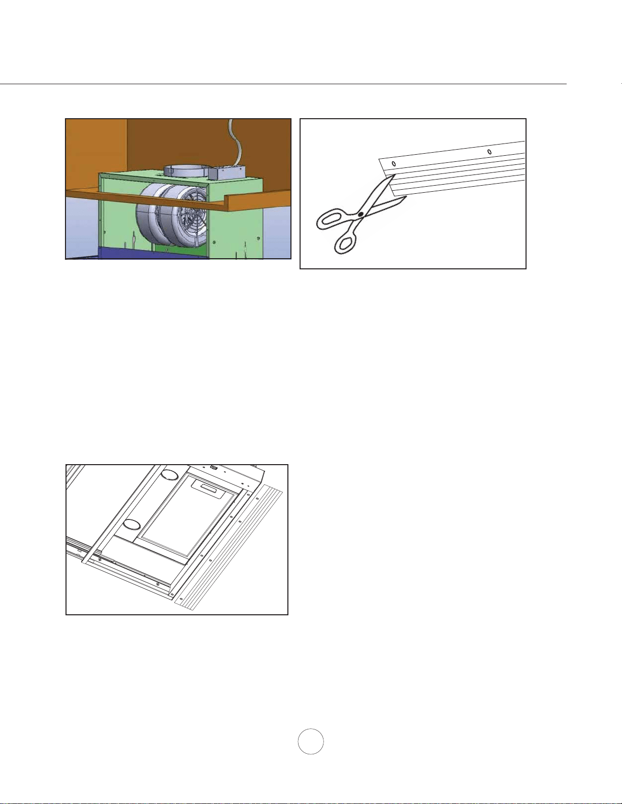
3ODFH´URXQGGXFWLQJRYHUEORZHUFROODUDQGVHFXUH
with aluminum duct tape. If using hood in ductless
recirculating mode turn to page 14.
,QVWDOOHOHFWULFDOZLULQJ1RWH$FDEOHORFNQRW
LQFOXGHGPD\EHUHTXLUHGE\ORFDOFRGHV&KHFN
with local requirements and codes, purchase and install
appropriate connector if necessary.
Make sure no packing material is inside hood. Power
up hood check for leaks around duct tape and verify all
functions.
Fig.9
0HDVXUHGLVWDQFHEHWZHHQEDFNRIUDQJHKRRGDQGZDOO
LIDQ\DQGFXW¿OOHUSDQHOWRWKHDSSURSULDWHGHSWK
using a utility knife or heavy-duty scissors.
,QVWDOO¿OOHUSDQHOWRERWWRPRIKRRGE\[
VFUHZVIRU´PRGHORU[VFUHZVIRU´PRGHO
14
www.zephyronline.com
Ductless recirculation is intended for applications where an exhaust duct work is not possible to be installed.
When converted, the hood functions as a recirculating hood rather than an exhaust hood. Fumes and exhaust
IURPFRRNLQJDUHGUDZQDQG¿OWHUHGE\DQRSWLRQDOFKDUFRDO¿OWHU7KHDLULVWKHQSXUL¿HGDQGUHFLUFXODWHGEDFN
within the home.
We recommend to ALWAYS exhaust air outside of the home by employing existing or installing new duct
ZRUNLISRVVLEOH7KHKRRGLVPRVWHIIHFWLYHDQGHI¿FLHQWDVDQH[KDXVWKRRG2QO\ZKHQWKHH[KDXVWRSWLRQ
is not possible should you recourse to converting the hood into a recirculating hood.
:KHQFRQYHUWHGWREHDUHFLUFXODWLQJKRRGDFKDUFRDO¿OWHULVUHTXLUHGRQWRSRIWKHGHFRUDWLYHPHVK¿OWHU
2UGHUDFFRUGLQJWRLWVSDUWQXPEHUEHORZ7KHGHFRUDWLYHPHVK¿OWHULVLQWHQGHGWRFDSWXUHUHVLGXHIURP
FRRNLQJDQGWKHRSWLRQDOFKDUFRDO¿OWHUKHOSVWRSXULI\IXPHVH[KDXVWHGIURPFRRNLQJIRUUHFLUFXODWLRQ
RECIRCULATING KIT (REQUIRED IF NOT DUCTED OUTSIDE THE HOME)
.LWLQFOXGHVFKDUFRDO¿OWHUEUDFNHWVDQGUHWXUQDLUYHQW
Hood Model Part No. Filters in Pkg.
ZPI ZRC-00PI 1
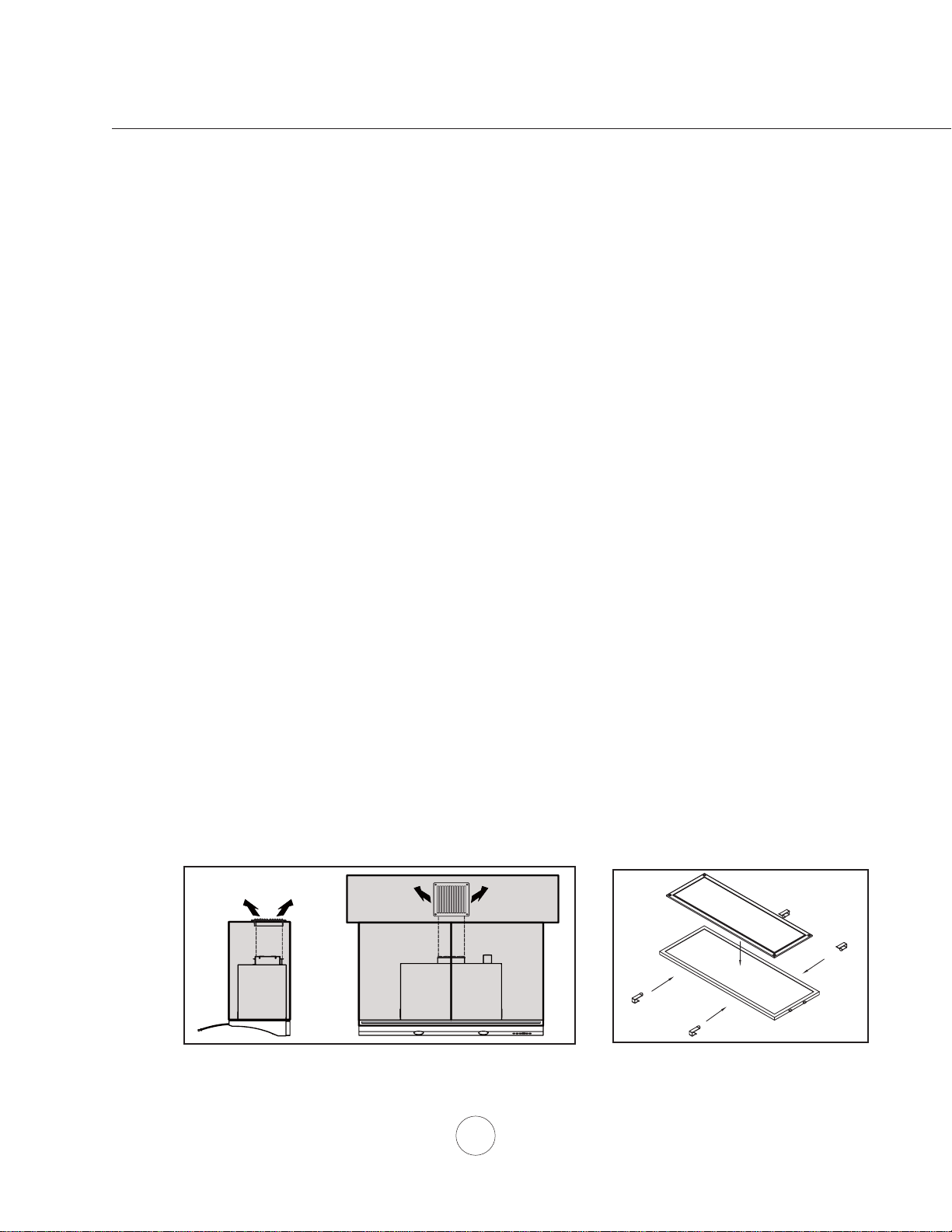
1. Purchase recirculating kit per the part number above.
5HPRYHGHFRUDWLYHPHVK¿OWHUIURPKRRGDQGSODFHFKDUFRDO¿OWHURQWRSRI
PHVK¿OWHU6HFXUHFKDUFRDO¿OWHUE\&FOLSVIURP=5&3,UHFLUFXODWLRQ
NLW&FOLSVIRUHDFKHQORQJDWHGVLGHRIFKDUFRDO¿OWHU)LJ
5HLQVWDOOGHFRUDWLYHPHVK¿OWHU
Charcoal Filter Replacement
Hood Model Part No. Qty to Order
ZPI Z0F-C0PI 1
4. In order to recirculate the air properly, a return air vent must be installed to
allow recycled air to be returned to the kitchen, Fig. 11. Ducting must be run
from the blower to the return air vent. The return air vent can be positioned
RQWRSRIWKHFDELQHWRULQDVRI¿WFHLOLQJ
&KDUFRDO¿OWHUPXVWEHUHSODFHGDIWHUHYHU\KRXUVRIXVHRUDSSUR[LPDWHO\
HYHU\WRPRQWKVEDVHGRQDQDYHUDJHGDLO\XVHRIKRXURIFRRNLQJWLPH
Fig.12
Fig.11
Installation – Recirculating Kit
15
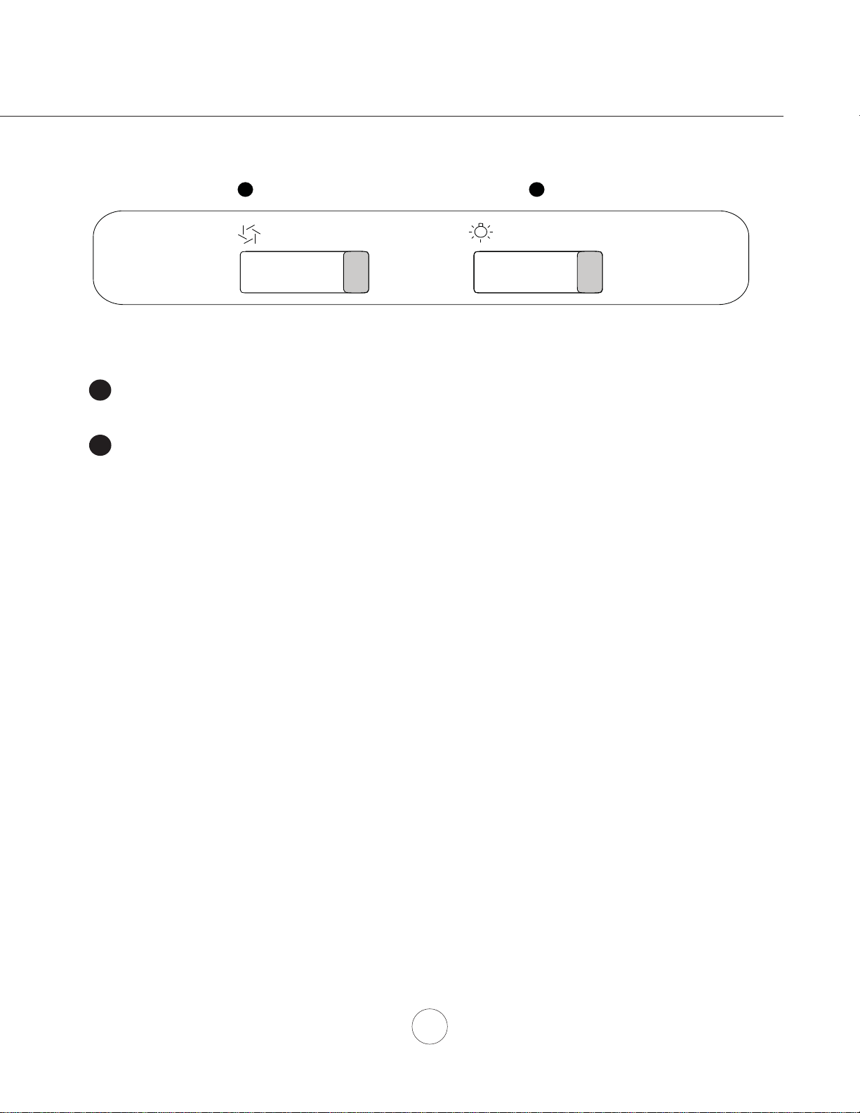
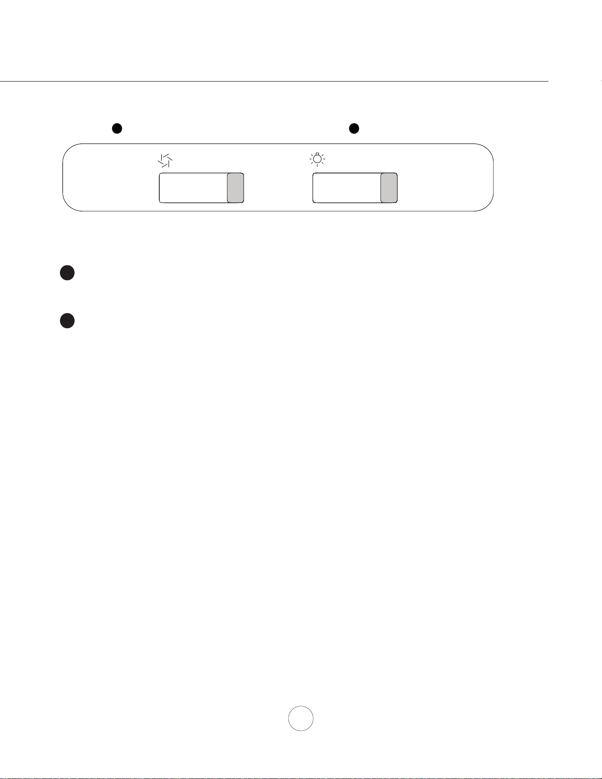
0 I II III
Blower On/Off Speed Selection
1
Lights Off/Dim/Bright
2
0 I II
BLOWER ON/OFF/SPEED SELECTION
0 is off, I is low speed, II is medium speed and III is high speed.
LIGHTS OFF/DIM/BRIGHT
0 is off, I is dim, and II is bright.
1
2
NOTE: Blower and lights will automatically shut off when the glass is closed
and turn back on when the glass is opened.
Blower and lights will not operate when the glass is closed.
Features & Controls – Slide Controls
16
www.zephyronline.com
SURFACE MAINTENANCE:
Do not use corrosive detergents, abrasive detergents or oven cleaners.
Do not use any product containing chlorine bleach or any product containing chloride.
Do not use steel wool or abrasive scrubbing pads which will scratch and damage surface.
Cleaning Stainless Steel
&OHDQSHULRGLFDOO\ZLWKZDUPVRDS\ZDWHUDQGFOHDQFRWWRQFORWKRUPLFUR¿EHUFORWK$OZD\VUXELQWKH
direction of the stainless steel grain. To remove heavier grease build up use a liquid degreaser detergent.
After cleaning use a non-abrasive stainless steel polish/cleaners, to polish and buff out the stainless luster
DQGJUDLQ$OZD\VVFUXEOLJKWO\ZLWKFOHDQFRWWRQFORWKRUPLFUR¿EHUFORWKDQGEXIILQWKHGLUHFWLRQRIWKH
stainless steel grain.
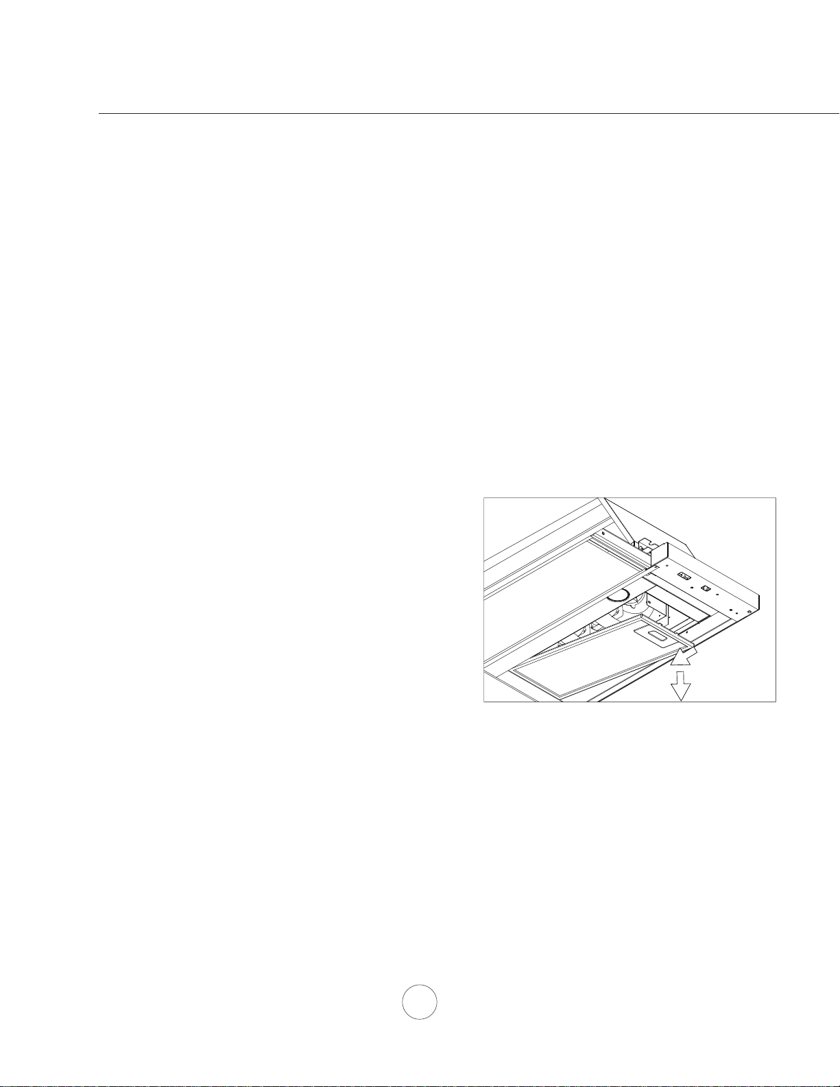
Decorative Mesh Filters
7KHPHVK¿OWHULQVWDOOHGE\WKHIDFWRU\LVLQWHQGHGWR¿OWHURXWUHVLGXHDQGJUHDVHIURPFRRNLQJ,WQHHGQRW
be replaced on a regular basis but is required to be kept clean.
Filter should be cleaned after every 30 hours of use or once a month.
Remove and clean by hand or in dishwasher
on low heat. Spray degreasing detergent and
leave to soak if heavily soiled.
'U\¿OWHUDQGUHLQVWDOOEHIRUHXVLQJKRRG
Replacing Mesh Filter
6KRXOG¿OWHUZHDURXWGXHWRDJHDQG
prolonged use, replace with the following part
number:
Hood Model: Part No. Qty. to Order.
ZPI 50200054 1
5HSODFHDQ\GDPDJHG¿OWHUWKDWKDVSXQFWXUHG
or broken mesh or damaged frame.
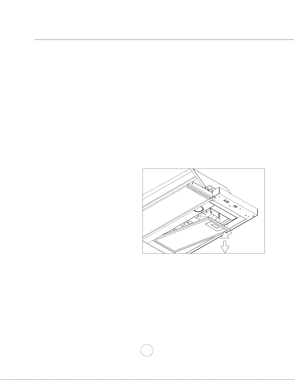
7RUHPRYHGHFRUDWLYHPHVK¿OWHU
3XVKLQ¿OWHUODWFK
7LOW¿OWHUGRZQDQGUHPRYHIURPKRRG
1
2
Maintenance – Hood and Filter Cleaning
17
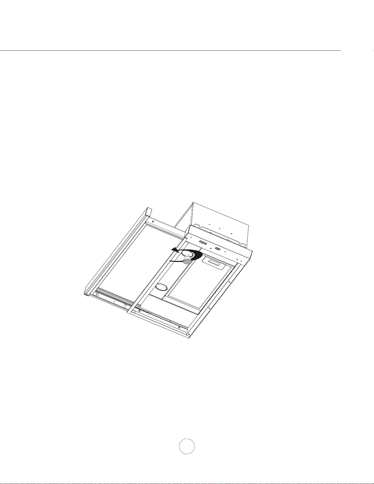
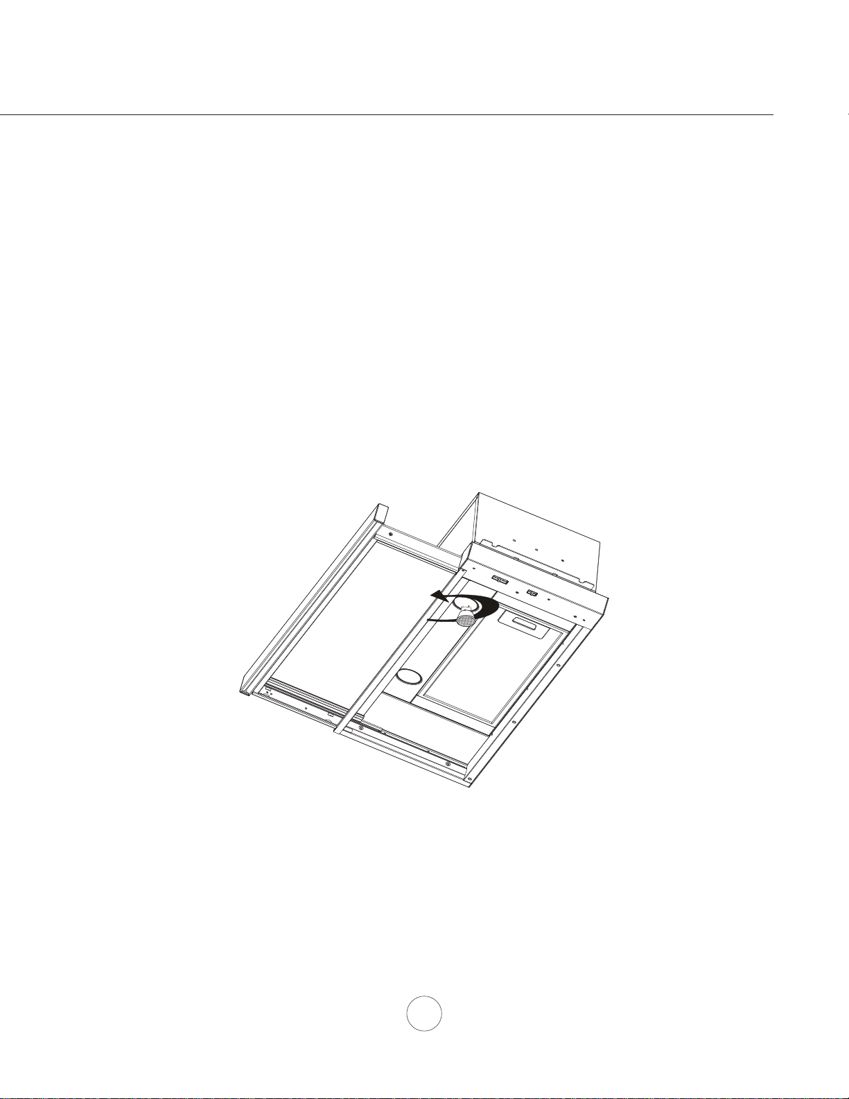
REPLACING LIGHT BULBS
CAUTION: Light bulb becomes extremely hot when turned on.
DO NOT touch bulb until switched off and cooled. Touching hot bulbs could cause serious burns.
Make sure all power is turned off and bulbs are not hot.
Remove by turning bulb counter-clockwise. Note: Bulb does not unscrew; it turns 60 degrees,
stops and falls out.
,IEXOEVDUHGLI¿FXOWWRWXUQGXHWRSURORQJHGXVH¿UPO\DWWDFKDJODVVVXFWLRQFXSDSSUR[LPDWHO\WKHGLDPHWHURI
the bulb or use a rubber/latex glove to grip the bulb and turn counter clockwise.
5HSODFHPHQWEXOEVDUHDYDLODEOHDWVSHFLDOW\OLJKWLQJVWRUHV3XUFKDVHW\SH05*8:KDORJHQ
For Zephyr part numbers please turn to page 20 of the manual.
Maintenance – Lights
18
www.zephyronline.com
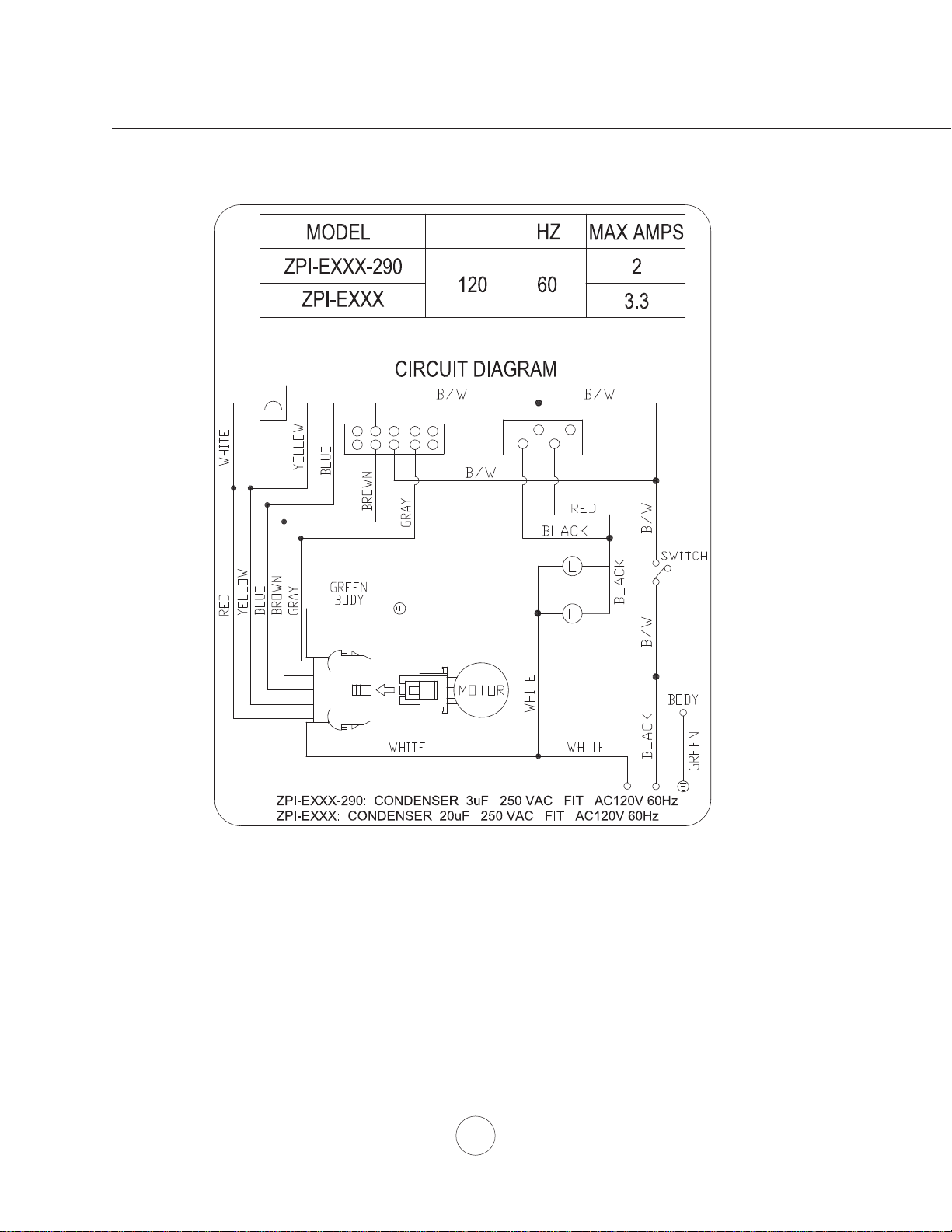
Wiring Diagrams
VOLTS
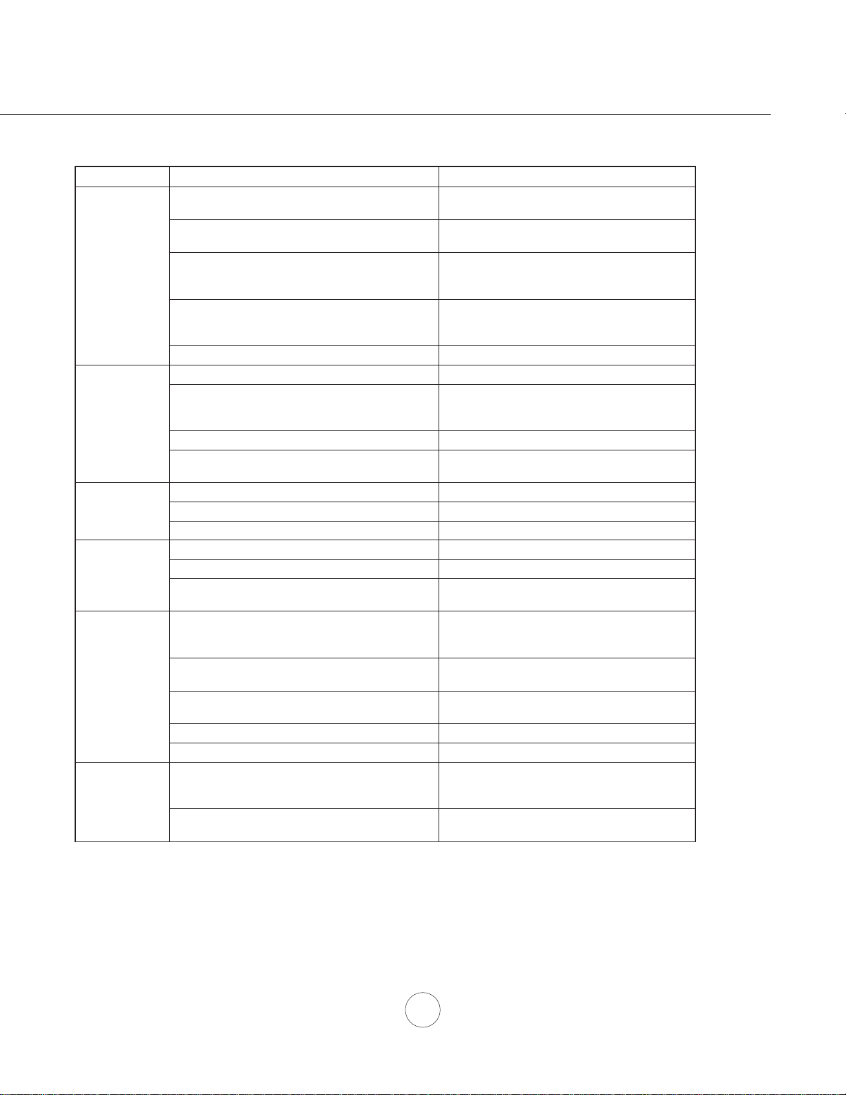
Troubleshooting
19
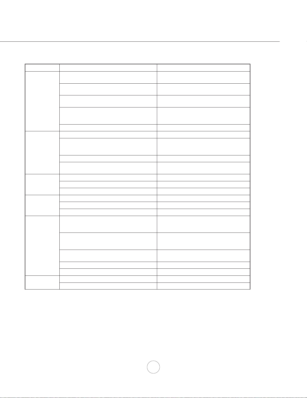
TROUBLESHOOTING PROCEDURES FOR ZPI
Issue Cause What to do
After installation,
the unit doesn’t
work.
1. The power source is not turned ON. 1. Make sure the circuit breaker and the unit’s
power is ON.
2. The power line and the cable locking connector
is not connecting properly.
2. Check the power connection with the unit is
connected properly.
3. Glass canopy is closed. 3. Glass canopy must be open to operate blower
and lights.
4. The switch board and control board wirings are
disconnected.
4. Make sure the wirings between the switch
board and control board are connected
properly.
5. The switch board or control board is defective. 5. Change the switch board or control board.
Light works, but
blower is not
turning.
1. The blower is defective, possible seized. 1. Change the blower.
2. The thermally protected system detects if the
blower is too hot to operate and shuts the blower
down.
2. The blower will function properly after the
thermally protected system cool down.
3. Damaged capacitor. 3. Change the capacitor.
4. The blower wire is not connected. 4. Make sure the blower wire is plugged into the
molex connector.
The unit is
vibrating.
1. The blower is not secure in place. 1. Tighten the blower screws in place.
2. Damaged blower wheel. 2. Change the blower.
3. The hood is not secured in place. 3. Check the installation of the hood.
The blower is
working, but the
lights are not.
1. Defective halogen bulb. 1. Change the halogen bulb.
2. The light bulb is loose. 2. Tighten the light bulb.
3. The light socket wires are disconnected. 3. Check the light socket wire connections.
The hood is
not venting out
properly.
1. The hood might be hanging too high from the
cook top.
1. Adjust the distance between the cook top and
the bottom of the hood within 24” and 32”
range.
2. Wind from opened windows or opened doors in
the surrounding area is affecting the ventilation
of the hood.
2. Close all the windows and doors to eliminate
WKHRXWVLGHZLQGÀRZ
3. Blockage in the duct opening or duct work. 3. Remove all the blocking from the duct work or
duct opening.
4. The direction of duct opening is against the wind. 4. Adjust the duct opening direction.
5. Using the wrong size of ducting. 5. Change the ducting to correct size.
0HWDO¿OWHULV
vibrating.
0HVK¿OWHULVORRVH &KDQJHWKHPHVK¿OWHU
2. Handle spring clip does not work properly 2. Adjust the handle until the spring clip works

20
www.zephyronline.com
DESCRIPTION PART#
Replacement Parts
/LJKW%XOE*8:+DORJHQHDFK =%
Aluminum Mesh Filter 50200054
Optional Accessories
Recirculatiing Kit ZRC-00PI
5HSODFHPHQW&KDUFRDO)LOWHUHDFK =)&3,
/LJKW%XOE*8/('HDFK =%
To order parts, visit us online at http://store.zephyronline.com or call us at 1.888.880.8368
List of Parts and Accessories

21
Warranty
1-888-880-8368
STAPLE YOUR RECEIPT HERE
TO OBTAIN SERVICE UNDER WARRANTY OR FOR ANY SERVICE RELATED QUESTIONS, please call:
Zephyr Ventilation, LLC (referred to herein as “we” or “us”) warrants to the original consumer purchaser (referred to
herein as “you” or “your”) of Zephyr products (the “Products”) that such Products will be free from defects in materials
or workmanship as follows:
Three Year Limited Warranty for Parts: For three years from the date of your original purchase of the Products, we
will provide, free of charge, Products or parts (including LED light bulbs, if applicable) to replace those that failed due to
manufacturing defects. We may choose, in our sole discretion, to repair or replace parts before we elect to replace the
Products.
One Year Limited Warranty for Labor: For one year from the date of your original purchase of the Products, we will
provide, free of charge, the labor cost associated with repairing the Products or parts to replace those that failed due to
manufacturing defects. After the first year from the date of your original purchase, you are responsible for all labor costs
associated with this warranty.
Warranty Exclusions: This warranty covers only repair or replacement, at our option, of defective Products or parts and
does not cover any other costs related to the Products including but not limited to: (a) normal maintenance and service
required for the Products and consumable parts such as fluorescent, incandescent or halogen light bulbs, mesh and char-
coal filters and fuses; (b) any Products or parts which have been subject to freight damage, misuse, negligence, accident,
faulty installation or installation contrary to recommended installation instructions, improper maintenance or repair (other
than by us); (c) commercial use of the Products or use otherwise inconsistent with its intended purpose; (d) natural wear
of the finish of the Products or wear caused by improper maintenance, use of corrosive and abrasive cleaning products,
pads, and oven cleaner products; (e) chips, dents or cracks caused by abuse or misuse of the Products; (f) service trips
to your home to teach you how to use the Products; (g) damage to the Products caused by accident, fire, floods, acts of
God; or (h) Custom installations or alterations that impact serviceability of the Products. If you are outside our service
area, additional charges may apply for shipping costs for warranty repair at our designated service locations and for the
travel cost to have a service technician come to your home to repair, remove or reinstall the Products. After the first year
from the date of your original purchase, you are also responsible for all labor costs associated with this warranty.
Limitations of Warranty. OUR OBLIGATION TO REPAIR OR REPLACE, AT OUR OPTION, SHALL BE YOUR SOLE AND
EXCLUSIVE REMEDY UNDER THIS WARRANTY. WE SHALL NOT BE LIABLE FOR INCIDENTAL, CONSEQUENTIAL OR
SPECIAL DAMAGES ARISING OUT OF OR IN CONNECTION WITH THE USE OR PERFORMANCE OF THE PRODUCTS.
THE EXPRESS WARRANTIES IN THE PRECEDING SECTION ARE EXCLUSIVE AND IN LIEU OF ALL OTHER EXPRESS
WARRANTIES. WE HEREBY DISCLAIM AND EXCLUDE ALL OTHER EXPRESS WARRANTIES FOR THE PRODUCTS,
AND DISCLAIM AND EXCLUDE ALL WARRANTIES IMPLIED BY LAW, INCLUDING THOSE OF MERCHANTABILITY AND
FITNESS FOR A PARTICULAR PURPOSE. Some states or provinces do not allow limitations on the duration of an implied
warranty or the exclusion or limitation of incidental or consequential damages, so the above limitations or exclusions may not
apply to you. To the extent that applicable law prohibits the exclusion of implied warranties, the duration of any applicable
implied warranty is limited to the same two-year period described above. Any oral or written description of the Products is for
the sole purpose of identifying the Products and shall not be construed as an express warranty. Prior to using, implementing
or permitting use of the Products, you shall determine the suitability of the Products for the intended use, and you shall assume
all risk and liability whatsoever in connection with such determination. We reserve the right to use functionally equivalent
refurbished or reconditioned parts or Products as warranty replacements or as part of warranty service. This warranty is not
transferable from the original purchaser and applies in the United States and Canada.
To Obtain Service Under Limited Warranty: To qualify for warranty service, you must: (a) notify us at the address or
telephone number stated below within 60 days of the discovery of the defect; (b) give the model number and part identifi-
cation number and serial number; and (c) describe the nature of any defect in the Product or part. At the time of the
request for warranty service, you must present evidence of your proof of purchase and proof of the original purchase
date. If we determine that the warranty exclusions listed abov
e apply or if you fail to provide the necessary documenta-
tion to obtain service, you will be responsible for all shipping, travel, labor and other costs related to the services.
Please check our website for any revisions, www.zephyronline.com.
Zephyr Ventilation Service Department, 2277 Harbor Bay Parkway, Alameda, CA 94502 1-888-880-8368
Limited Warranty
AUG14.0401
Proof of the original purchase
date is needed to obtain
service under warranty

22
www.zephyronline.com
PRODUCT REGISTRATION
Congratulations on your Zephyr range
hood purchase! Please take a moment to
register your new range hood at
www.zephyronline.com/registration
Zephyr Ventilation | 2277 Harbor Bay Pkwy. | Alameda, CA 94502 | 1.888.880.8368
Prompt registration helps in more ways
than one.
IT’S IMPORTANT
Ensures warranty coverage should you
need service.
Ownership verification for insurance
purposes.
Notification of product changes or recalls.
Guide d’utilisation, d’entretien et d’installation
Numéro de modèle : _________________
Numéro de série : _________________
NOV17.0701 © Zephyr Ventilation LLC.
www.zephyronline.com
Pisa
ZPI-E24AG
ZPI-E24AG290
ZPI-E30AG
ZPI-E30AG290
ZPI-E36AG
ZPI-E36AG290
ZPI-E24AW
ZPI-E24AW290
ZPI-E30AW
ZPI-E30AW290

www.zephyronline.com

1
MISE EN GARDE DE SÉCURITÉ ......................................... 2-3
LISTE DU MATÉRIEL
................................................................. 4
INSTALLATION
Feuille de calcul pour le conduit
........................... 5
Espace libre et hauteur de montage
................... 6
Options d’installation pour le conduit
.................. 7
6SpFL¿FDWLRQVGHODKRWWH
......................................... 8
Préparation de l’armoire
........................................... 9
Conversion pour conduit horizontal
..................... 10
Montage de la hotte
................................................... 11-13
Trousse de recirculation d’air
................................. 14
COMMANDES
Curseurs
........................................................................ 15
ENTRETIEN
1HWWR\DJHGHODKRWWHHWGX¿OWUH
.......................... 16
Lumières
......................................................................... 17
SCHÉMA DE CÂBLAGE
.......................................................... 18
DÉPANNAGE
................................................................................ 19
LISTE DES PIÈCES ET ACCESSOIRES
.......................... 20
GARANTIE
...................................................................................... 21
ENREGISTRMENT DU PRODUIT
........................................ 22
Table des matières

Mise en garde de sécurité
LISEZ ET CONSERVEZ CES INSTRUCTIONS
2
www.zephyronline.com
AVERTISSEMENT
POUR RÉDUIRE LES RISQUES D’INCENDIE OU DE DÉCHARGE ÉLECTRIQUE, N’UTILISEZ PAS CET APPAREIL AVEC UN TABLEAU
DE COMMANDE À SEMI-CONDUCTEURS.
AVERTISSEMENT
POUR RÉDUIRE LES RISQUES D’INCENDIE, DE DÉCHARGE ÉLECTRIQUE OU DE BLESSURE, RESPECTEZ CES CONSIGNES :
a. N’utilisez cet appareil que de la manière prévue par le fabricant. Si vous avez des questions, communiquez avec le fabricant.
b. Avant de procéder au nettoyage ou à l’entretien de l’appareil, éteignez l’alimentation du panneau électrique et bloquez le dispositif de
déconnexion pour éviter que l’alimentation électrique ne soit accidentellement rallumée. Si le dispositif de sectionnement d’électricité ne peut
être bloqué, attachez un avertissement (comme une étiquette) bien en vue sur le tableau électrique.
ATTENTION
Pour ventilation générale seulement. N’utilisez pas cet appareil pour évacuer des vapeurs et des matériaux explosifs ou dangereux. Prenez garde
lors de l’utilisation d’agents nettoyants ou de détergents. Ne devrait être utilisé que dans la cuisine de votre maison.
AVERTISSEMENT
POUR RÉDUIRE LES RISQUES DE FEU DE GRAISSE SUR LA SURFACE DE CUISSON :
a. Ne laissez jamais l’appareil sans surveillance lors de son utilisation à haute température. Les débordements par bouillonnement causent de la
fumée et des déversements de graisse qui peuvent prendre feu. Faites chauffer l’huile à des températures basses ou moyennes.
E $OOXPH]WRXMRXUVODKRWWHORUVTXHYRXVFXLVLQH]jKDXWHWHPSpUDWXUHRXTXHYRXVIDLWHVÀDPEHUGHVDOLPHQWV
F 1HWWR\H]IUpTXHPPHQWOHVYHQWLODWHXUVGHODKRWWH/DJUDLVVHQHGHYUDLWMDPDLVV¶DFFXPXOHUGDQVOHVYHQWLODWHXUVRXOHV¿OWUHV
d. Utilisez des poêlons aux dimensions adéquates. Utilisez toujours une batterie de cuisine correspondant aux dimensions de l’élément.
H $VVXUH]YRXVTXHOHYHQWLODWHXUOHV¿OWUHVHWOHVVXUIDFHVRODJUDLVVHSRXUUDLWV¶DFFXPXOHUVRQWWRXMRXUVSURSUHV
f. Utilisez le réglage haut de la hotte seulement lorsque nécessaire.
g. Ne laissez pas la hotte sans surveillance lorsque vous cuisinez.
h. Utilisez toujours une batterie de cuisine et des ustensiles convenant au type et à la quantité de nourriture que vous préparez.
AVERTISSEMENT
POUR RÉDUIRE LES RISQUES DE BLESSURE LORS D’UN INCENDIE SUR LA SURFACE DE CUISSON :
a. ÉTOUFFEZ LES FLAMMES avec un couvercle, une plaque à biscuits ou un plateau de métal et éteignez ensuite le brûleur. PRENEZ GARDE
$8;5,648(6'(%5Ó/85(6LOHVÀDPPHVQHGLVSDUDLVVHQWSDVe9$&8(=/(6/,(8;(7$33(/(=/(6(59,&('¶,1&(1',(
b. NE PRENEZ JAMAIS UN POÊLON EN FEU – Vous pourriez vous brûler.
c. N’UTILISEZ PAS D’EAU, ou un linge à vaisselle mouillé – une violente explosion de vapeur s’ensuivra.
d. Utilisez un extincteur SEULEMENT si :
1. Vous savez que vous possédez un extincteur de classe ABC et vous savez vous en servir.
2. Le feu est faible et ne s’est pas répandu depuis son point d’origine.
3. Vous avez appelé le service d’incendie.
9RXVSRXYH]VRUWLUIDFLOHPHQWGHO¶HQGURLWRYRXVFRPEDWWH]OHIHX
AVERTISSEMENT
POUR RÉDUIRE LES RISQUES D’INCENDIE, DE DÉCHARGE ÉLECTRIQUE OU DE BLESSURE, SUIVEZ LES CONSIGNES SUIVANTES :
D /HVWUDYDX[G¶LQVWDOODWLRQHWGHFkEODJHpOHFWULTXHGRLYHQWrWUHIDLWVSDUXQHSHUVRQQHTXDOL¿pHVHORQOHVVWLSXODWLRQVGHWRXVOHVQRUPHVHW
standards en vigueur, dont les normes des constructions ayant une cote de résistance au feu.
b. Pour prévenir les contre-explosions, une certaine quantité d’air est nécessaire pour la combustion et l’évacuation des gaz par le carneau
(cheminée) de l’appareil de combustion. Respectez les directives du fabricant d’outillage de chauffage et les normes de sécurité comme celles
publiées par la NFPA (Association nationale des services d’incendie), par la Société américaine des ingénieurs en chauffage, réfrigération et
climatisation (ASHRAE) et par les normes des autorités locales.
c. Lorsque vous coupez ou percez un mur ou un plafond, assurez-vous de ne pas endommager le câblage électrique ou toute autre installation
technique dissimulée.
d. Les ventilateurs canalisés doivent toujours évacuer l’air à l’extérieur.
e. N’installez JAMAIS un interrupteur à une distance atteignable depuis un bain ou une douche.
f. Assurez-vous que l’alimentation électrique est éteinte avant de procéder à l’installation, au câblage ou à l’entretien de l’appareil

Mise en garde de sécurité
3
ATTENTION
POUR RÉDUIRE LES RISQUES D’INCENDIE, N’UTILISEZ QUE DES CONDUITS D’AÉRATION EN MÉTAL.
ATTENTION
Pour réduire les risques d’incendie et pour évacuer l’air convenablement, assurez-vous de canaliser l’air à l’extérieur de
la maison. N’installez pas l’échappement du conduit dans les espaces entre les murs, le plafond, le grenier, les vides
sanitaires ou le garage.
FONCTIONNEMENT
/DLVVH]WRXMRXUVOHVJULOOHVGHVUHWpHWOHV¿OWUHVHQSODFH6DQVFHVpOpPHQWVOHVYHQWLODWHXUVHQPDUFKHSRXUUDLHQW
accrocher des cheveux, des doigts ou des vêtements amples.
Le fabricant se dégage de toute responsabilité dans les cas de non-respect des instructions transmises dans le présent
manuel pour l’installation, l’entretien et l’utilisation adéquate du produit. Le fabricant se dégage également de toute
UHVSRQVDELOLWpSRXUGHVEOHVVXUHVTXLUpVXOWHUDLHQWGHODQpJOLJHQFHORUVGHO¶XWLOLVDWLRQ'HSOXVODJDUDQWLHSUHQG¿Q
automatiquement lors de l’entretien inapproprié de l’appareil.
*NOTE : Veuillez consulter le www.zephyronline.com pour obtenir des révisions avant de procéder à des travaux sur
commande.
EXIGENCES ÉLECTRIQUES
Important :
Respectez tous les codes et règlements en vigueur.
Il est de la responsabilité du client de :
&RPPXQLTXHUDYHFXQLQVWDOODWHXUpOHFWULFLHQTXDOL¿p
- S’assurer que l’installation électrique est adéquate et qu’elle respecte le Code national de l’électricité, la plus récente
édition* du ANSI/NFPA 70 ou des normes du CSA C22.1-94, le Code canadien de l’électricité, section 1, la plus récente
édition** du code C22.2 No.0-M91 ainsi que tous les codes et réglements en vigueur.
6LOHVFRGHVSHUPHWWHQWO¶XWLOLVDWLRQG¶XQ¿OGHJDUGHLVROpHWTXHYRXVHQXWLOLVH]XQLOHVWUHFRPPDQGpTX¶XQpOHFWULFLHQ
TXDOL¿pGpWHUPLQHVLOHFKHPLQHPHQWGX¿OHVWDGpTXDW
N’effectuez pas la mise à la terre à un tuyau de gaz.
'HPDQGH]jXQpOHFWULFLHQTXDOL¿pVLYRXVQ¶rWHVSDVFHUWDLQTXHODKRWWHDpWpPLVHjODWHUUHDGpTXDWHPHQW
N’introduisez aucun fusible dans le circuit neutre ou de mise à la terre.
*National Fire Protection Association Batterymarch Park, Quincy, Massachusetts 02269
** CSA International 8501 East Pleasant Valley Road, Cleveland, Ohio 44131-5575
Cet appareil requiert une alimentation électrique de 120V 60Hz. Il doit être connecté à un circuit terminal individuel
dûment mis à la terre, protégé par un disjoncteur de circuit ou un fusible temporisé de 15 ou 20 ampères. Le câblage doit
FRPSWHU¿OVDYHFPLVHjODWHUUH9HXLOOH]YRXVUpIpUHUDX'LDJUDPPHpOHFWULTXHpWLTXHWpVXUO¶DSSDUHLO
Un raccord de câble (non inclus) pourrait également être exigé par les normes et réglementations locales. Informez-vous
des exigences et des normes locales. Achetez et installez le connecteur approprié si nécessaire.
Liste du matériel
4
www.zephyronline.com
(3) Capuchons de
connexion
(1) Ventouse
(1) Registre circulaire de 6 po (préinstallé)
(1) Trousse de quincaillerie
PIÈCES FOURNIES
CONTENU DE LA TROUSSE DE QUINCAILLERIE
PIÈCES NON FOURNIES
- Conduit et tous les outils d’installation
- Raccord de câble (si exigé par les codes en vigueur)
(2) Ampoules halogènes, GU-10 50W
(1) Filtre à tamis
(2) M4 x 1”
(1) Hotte avec plaque de verre coulissante
(1) Panneau de remplissage
(4) M3.5x10
ZPI-E36AG290 x 5
(4) M4 x 16mm
(2) Supports d’installation superieurs
(2) Supports d’installation inferieurs
24” Modeles
(2) M4 x 8
(4) 3/16 x 3/8”
(4) 3/16 x 40
(24” modeles)
(24” modeles)
(24” modeles)
5
Tot a l
=
3- 1/4” x 10”
1 pi x ( ) =
pi
5 pi x ( ) =
pi
20 pi x ( ) =
pi
6”, 7”, 8”, 10”
15 pi
x ( ) =
pi
6”, 7”, 8”, 10”
9 pi x ( ) =
pi
pi
6”, 7”, 8”, 10”
1 pi x ( ) =
pi
Tot a l
=
6”, 7”, 8”, 10”
30 pi x ( ) =
pi
pi
pi
pi
6”, 7”, 8”, 10”
30 pi x ( ) =
pi
1 pi x ( ) =
pi
16 pi x ( ) =
pi
8 pi x ( ) =
pi
23 pi x ( ) =
pi
7” to 6” or
8” to 7” circ.
reducteur
conique
25 pi x ( ) =
pi
3- 1/4” x 10”
15 pi x ( ) =
pi
3- 1/4” x 10”
9 pi x ( ) =
pi
3- 1/4” x 10”
24 pi x ( ) =
pi
30 pi x ( ) =
pi
pi x ( ) =
pi
15
6”, 7“, 8”
circ.
bouchone de
l’air
Pièces de conduit
Longueur x
Nombre utilisé
rect., droit
circ., droit
rect.,
coude à 90º
rect.,
coude à 45º
rect.,
coude plat
à 90º
circ.,
coude à 90º
coude à 45º
Sous-total - colonne 1=
Longueur maximale du conduit d’aération :
Pour un mouvement d’air convenable, la longueur totale d’un conduit
d’aération ne devrait pas compter plus que l’équivalent de 100 pieds.
Pièces de conduit
Longueur x
Nombre utilisé
6” circ. à
rect. de
3-1/4" x 10",
coude à 90º
6” circ. à
rect. de
3-1/4" x 10"
6” circ. à
rect. de
3-1/4" x 10"
6” circ. à
rect. de
3-1/4" x 10",
coude à 90º
7” circ. à
rect. de
3-1/4" x 10"
7” circ. à
rect. de
3-1/4" x 10",
coude à 90º
3-1/4” x 10”
embout mural
rect./registre
embout
mural
circ./registre
chapeau de
toiture circ.
Sous-total - colonne 2 =
Sous-total - colonne 1 =
Total du conduit =
Installation – Feuille de calcul pour le conduit d’aération
Installation – Espace libre et hauteur de montage
6
www.zephyronline.com
CONDUIT D’AÉRATION
Un conduit circulaire de 6” doit être utilisé pour
assurer une circulation d’air maximale.
N’utilisez que des conduits en métal rigide. Les
conduits souples peuvent réduire la circulation
d’air de 50 %.
Utilisez la feuille de calcul pour obtenir la longueur
totale du conduit.
Lorsqu’il est possible de le faire, diminuez
TOUJOURS le nombre de pièces et de
changements de direction. Si un long tronçon de
conduit est nécessaire, augmentez le diamètre du
conduit de 6” à 7” ou 8”.
Si des changements de direction ou des
adaptateurs sont nécessaires, installez-les le
plus loin possible de l’ouverture et le plus éloigné
possible l’un de l’autre.
La hauteur de montage minimale ne devrait pas
être moins de 24 po et plus de 32 po.
Il est important d’installer la hotte à la hauteur
de montage adéquate. Les hottes installées
trop basses pourraient être endommagées par
la chaleur en plus de présenter des risques
d’incendie plus élevés tandis que les hottes
LQVWDOOpHVWURSKDXWHVVHURQWGLI¿FLOHVjDWWHLQGUH
HWYHUURQWOHXUHI¿FDFLWpHWOHXUUHQGHPHQWUpGXLWV
Si elles sont disponibles, consultez les exigences
de hauteur d’espace libre requise par le fabricant
de la cuisinière ainsi que la hauteur recommandée
de montage de la hotte au-dessus de la surface
de cuisson. Informez-vous toujours des normes et
des réglementations locales en vigueur pour toute
différence par rapport aux normes du fabricant.
ENDOMMAGEMENT LORS DE LA LIVRAISON/
INSTALLATION :
9HXLOOH]YRXVDVVXUHUTXHWRXWHVOHVSLqFHV
de l’appareil ne sont pas endommagées avant
l’installation.
6LO¶DSSDUHLOHVWHQGRPPDJpGXUDQWODOLYUDLVRQ
UHWRXUQH]O¶DSSDUHLOjO¶HQGURLWRYRXVO¶DYH]
acheté pour réparation ou remplacement.
6LO¶DSSDUHLOHVWHQGRPPDJpSDUOHFOLHQWOD
réparation ou le remplacement est à la charge du
client.
6LO¶DSSDUHLOHVWHQGRPPDJpSDUO¶LQVWDOODWHXU
(si autre que le client), le client et l’installateur
doivent en venir à une entente pour la réparation
ou le remplacement.
36”
24” min.
32” max.
7
AVERTISSEMENT DE RISQUE D’INCENDIE
N’évacuez ou ne terminez JAMAIS l’échappement du conduit dans les espaces entre les murs, les vides
sanitaires, le plafond, le grenier, ou le garage. Tous les échappements doivent être dirigés à l’extérieur de la
maison.
N’utilisez que des conduits en métal pour cloison simple.
Fixez toutes les pièces du conduit avec des vis à tôle et isolez tous les joints avec du ruban adhésif en toile ou
GXUXEDQUpÀHFWHXUFHUWL¿p
Quelques options pour le conduit d’aération
Installation – Options pour le conduit d’aération
Retombée de plafond
ou vide sanitaire
Pente de la
toiture avec
solin et chapeau
ductless
recirculating
w/ gravity damper
side wall cap
ductless
recirculating
soffit
8
www.zephyronline.com
Installation – 6SpFL¿FDWLRQVGHODKRWWH
DESSUS
DEVANT
CÔTÉ
6
L/C
"
3
7/16”
3/4”
23
7/8”(24”)
2
9
7/8”(30”),
35
7/8”(36”)
19
1
11/16”
9
9/16”
11
1/4”
9/16”
5
3/16” (30”)
11-
15/16
” - 18-
3/4
”
11
1/8”
13/16”
9 7/8”
1
1/8
”
4
/15 16”
fermé Ouvert
3 7/16”
3/8” -
2 1/4"*
*panneau de
remplissage
arrière ajustabl
e
L/C
3
7/16”
11
1/4”
Ø
6”
ARRIÈRE
8
3/16” (36”)
2
3/16” (24”)
9
7 3/4”
7”
10-
1/8”
19-
7/8”
C/L
1-
15/16”
*11-
1/2”
*6-3/16”
7”
Installation – Préparation de l’armoire
1. Déterminez l’emplacement de la ligne centrale et tracez-la sur le mur et le dessous de
l’armoire avec un crayon.
2. Si le dessous de l’armoire est enfoncé, vous devez installer des pièces de renforcement
en bois pour vous assurer de l’alignement adéquat de la hotte avec le dessous de
l’armoire. Les morceaux de bois doivent être de niveau avec le dessous de l’armoire.
3. Consultez les dimensions de la Fig. 1 et faites un trou dans la partie inférieure de
O¶DUPRLUHD¿QGHFUpHUXQHRXYHUWXUHSRXYDQWDFFXHLOOLUODKRWWH3RXUOHVDUPRLUHVVDQV
charpente, mesurez une distance de 1-15/16 po à partir de l’avant de la partie inférieure
de l’armoire.
FIG.1
* Dimensions utilisées pour l’option du conduit arrière
Rebord avant
Poignée de verre
FIG.2
10
www.zephyronline.com
(QOHYH]OH¿OWUHjWDPLVHQDOXPLQLXP'HSXLV
l’intérieur de la hotte, débranchez le câble du
ventilateur, situé du côté droit de la hotte
2) Enlevez les six (6) vis de la partie supérieure de
la hotte et les six (6) vis de l’arrière de la hotte
qui retiennent la plaque du ventilateur au bâti de
la hotte.
3) Retirez le ventilateur et la plaque du ventilateur
de la hotte et replacez le ventilateur dans la hotte
de façon à ce que le collier du ventilateur sorte à
l’arrière du bâti de la hotte. Réinstallez la plaque
du ventilateur au bâti de la hotte en utilisant les
douze (12) vis préalablement enlevées à l’étape 2.
Rebranchez le ventilateur.
Installation – &RQYHUVLRQKRUL]RQWDOHInstallation – &RQYHUVLRQKRUL]RQWDOH
CONVERSION VERTICALE D’UN CONDUIT CIRCULAIRE HORIZONTAL DE 6 PO
11
Installation - 0RQWDJHGHODKRWWH
2) Ouvrez les portes de l’armoire. Soulevez la hotte
et faites-la glisser dans l’ouverture sous l’armoire
(Fig. 3). Assurez-vous que l’ouverture correspond
aux dimensions indiquées à la page 9 (Fig.1).
3) Des attaches à ressort sont situées des côtés
gauche et droit du bâti de la hotte. Ces attaches
retiendront temporairement la hotte en place
(Fig. 4).
AVERTISSEMENT: Le câblage électrique doit être effectué par une ou des personnes qualifiées
selon les stipulations de tous les normes et standards en vigueur. Éteignez l’alimentation électrique
à l’entrée de service avant de procéder au câblage.
!
1) Préparez le câblage électrique et le conduit dans l’armoire. Les emplacements de la boîte de connexion et de
la prise du ventilateur sont indiqués à la page 8.
FIG.3
FIG.4
4) Fixez les supports superieurs des cotes gauche et
droit du bati de la hotte a l’aide de deux (2) vis de
3/16 x 3/8 po chacun (Fig.5). Assurez-vous que les
deux (2) trous des ecrous prisonniers du support
sont orientes vers le bas.
5) Fixez les supports d’installation inferieurs sous
les supports d’installation superieurs, situes des
cotes gauche et droit du bati (Fig.6).
FIG.5 FIG.6
12
www.zephyronline.com
8) Outre corps de la hotte sécurisé à la base de
l’armoire par (4 vis) M4 x 16mm à travers le fond de
la hotte.
1
9) Fixez deux (2) vis à bois (A) dans les trous à vis
GHVF{WpVJDXFKHHWGURLWGHO¶RXYHUWXUHGX¿OWUH
A
´0RGHOH'HSXLV,¶LQWHULHXUGHODKRWWH¿[H]XQH
(1) vis M4x8 dans chaque support d’installation
inferieur. La position de cette vis s’ajuste en
fonction de l’epaisseur de l’armoire (Fig.7).
7) 24” Modele. Installez deux (2) vis 3/16x40 dans
les ecrous prisonniers de chaque support
d’insatllation superieur. Serrez les vis our
aduster la hauteur de la hotte jusqu’a ce qu’il n’y
ait plus d’espace entre le dessous de l’armoire
HWO¶DYDQWGHOD+RWWH¿J
FIG.7 FIG.8
Installation – 0RQWDJHGHODKRWWH
13
Installation – 0RQWDJHGHODKRWWH
10) Placez le conduit circulaire de 6 po sur le collier du
YHQWLODWHXUHW¿[H]OHDYHFGXUXEDQjFRQGXLWHQ
aluminium. Si vous utilisez la hotte avec le mode de
recirculation d’air, allez à la page 13.
Installez les composantes électriques. Note :
Les codes locaux peuvent exiger l’utilisation d’un
raccord de câble (non inclus). Consultez les codes
et exigences en vigueur, puis achetez et installez le
connecteur approprié s’il le faut.
Assurez-vous qu’il ne reste aucun élément
d’emballage à l’intérieur de la hotte. Allumez la
KRWWHSRXUYpUL¿HUV¶LO\DGHVIXLWHVDXWRXUGH
connexions et assurez-vous que la hotte est
fonctionnelle.
FIG.9
1
2
11) Mesurez la distance entre l’arrière de la hotte et le
mur (s’il y a lieu) et coupez avec un couteau tout
usage ou avec des ciseaux robustes le panneau de
remplissage d’une profondeur adéquate.
12) Fixez le panneau de remplissage à la partie
inférieure de la hotte avec quatre (4) vis M3.5x10 de
30” et (5) vis M3.5x10 de 36”.
14
www.zephyronline.com
/DFRQ¿JXUDWLRQGHUHFLUFXODWLRQG¶DLUDpWpFRQoXHSRXUOHVDSSOLFDWLRQVRLOHVWLPSRVVLEOHG¶LQVWDOOHUXQFRQGXLW
d’aération. Lorsque transformée, la hotte fonctionne comme une hotte de recirculation d’air plutôt que comme un
V\VWqPHG¶pYDFXDWLRQG¶DLU/HVYDSHXUVHWIXPpHVGHFXLVVRQVRQWDVSLUpHVHW¿OWUpHVSDUXQHQVHPEOHRSWLRQQHOGH
¿OWUHVjFKDUERQ/¶DLUHVWHQVXLWHSXUL¿pHWUHGLULJpjO¶LQWpULHXUGHODPDLVRQ
Nous recommandons de TOUJOURS évacuer l’air à l’extérieur de la maison en utilisant le conduit en place ou, s’il y
DSRVVLELOLWpHQLQVWDOODQWXQQRXYHDXFRQGXLW/DKRWWHHVWSOXVHI¿FDFHORUVTX¶XWLOLVpHFRPPHV\VWqPHG¶pYDFXDWLRQ
G¶DLU9RXVQHGHYULH]UHFRXULUjODFRQ¿JXUDWLRQGHUHFLUFXODWLRQG¶DLUTXHORUVTX¶LOHVWLPSRVVLEOHG¶LQVWDOOHUXQFRQGXLW
d’aération.
/RUVTXHODKRWWHHVWFRQYHUWLHDYHFODWURXVVHGHUHFLUFXODWLRQG¶DLUXQ¿OWUHjFKDUERQGRLWrWUHLQVWDOOpVXUOH¿OWUHj
WDPLVGpFRUDWLI&RPPDQGH]OHHQYRXVUpIpUDQWDXQXPpURGHSLqFHFLGHVVRXV/H¿OWUHjWDPLVGpFRUDWLIHVWFRQoX
SRXUFDSWHUOHVUpVLGXVGHFXLVVRQHWOH¿OWUHjFKDUERQRSWLRQQHODLGHjODSXUL¿FDWLRQGHVYDSHXUVHWIXPpHVGHOD
cuisson lors de recirculation de l’air.
TROUSSE DE RECIRCULATION D’AIR (REQUIS SI AUCUN CONDUIT N’ÉVACUE L’AIR À
L’EXTÉRIEUR)
/DWURXVVHFRPSUHQGXQ¿OWUHjFKDUERQGHVVXSSRUWVHWXQpYHQWGHUHWRXUG¶DLU
0RGqOHGHKRWWH 1XPpURGHSLqFH )LOWUHVSDUSDTXHW
ZPI ZRC-00PI 1
1. Procurez-vous la trousse de recirculation d’air en utilisant le numéro de pièce ci-dessus.
5HWLUH]OH¿OWUHjWDPLVGpFRUDWLIGHODKRWWHHWLQVWDOOH]OH¿OWUHjFKDUERQVXUOH¿OWUHjWDPLV)L[H]OH¿OWUHj
charbon en place à l’aide de quatre attaches en C, fournies avec la trousse de recirculation d’air ZRC-00PI, soit
GHX[DWWDFKHVSDUF{WpORQJGX¿OWUHjFKDUERQ)LJ
5pLQVWDOOH]OH¿OWUHjWDPLVGpFRUDWLI
4. Pour assurer une recirculation adéquate de l’air, un évent de retour d’air doit être installé pour permettre à l’air
recyclé de retourner dans la cuisine, Fig. 11. Le conduit doit aller du ventilateur à l’évent de retour d’air. L’évent de
retour d’air peut être installé sur le dessus de l’armoire ou dans le plafond ou vide sanitaire.
/H¿OWUHjFKDUERQGRLWrWUHUHPSODFpDSUqVKHXUHVG¶XWLOLVDWLRQRXDSSUR[LPDWLYHPHQWWRXVOHVPRLVj
raison de 1-2 heures d’utilisation quotidienne).
5HPSODFHPHQWGX¿OWUHjFKDUERQ
0RGqOHGHKRWWH Numéro de pièce4XDQWLWpjFRPPDQGHU
ZPI ZRC-00PI 1
Installation – Trousse de recirculation d’air
FIG.11
15
0 I II III
Ventilateur : Marche/Arrêt Choix de vitesse
1
Allumées/Veilleuse/Éteintes
2
0 I II
VENTILATEUR : MARCHE/ARRÊT CHOIX DE VITESSE
À 0, le ventilateur est éteint, à I il est à basse vitesse, à II il est à la vitesse moyenne et à III il est à
la vitesse élevée.
LUMIÈRES : NORMAL/VEILLEUSE/ARRÊT
À 0, les lumières sont éteintes, à I elles sont en mode veilleuse et à II elles sont à forte intensité.
1
2
NOTE: Le ventilateur et les lumières s’éteignent automatiquement lorsque le pavillon
de verre est en position fermée et se rallument lorsqu’il est en position ouverte.
Le ventilateur et les lumières ne fonctionnent pas lorsque le pavillon de verre
est en position fermée.
Commandes - Curseurs
16
www.zephyronline.com
ENTRETIEN DES SURFACES
Nettoyez régulièrement les surfaces de la hotte avec de l’eau savonneuse chaude et un chiffon de coton
propre. N’utilisez pas de détergent abrasif ou corrosif, de laines d’acier ou de tampons à récurer; ils
égratigneront et endommageront les surfaces.
Pour les taches plus tenaces, utilisez du produit dégraissant liquide.
Après le nettoyage, vous pouvez polir les surfaces avec des produits de polissage à acier inoxydable non
abrasifs pour redonner de l’éclat et du lustre aux surfaces. Frottez toujours doucement, avec un chiffon de
coton propre, et dans le sens du grain.
N’utilisez pas de produits à blanchir au chlore ou d’agents nettoyants « orange ».
)LOWUHjWDPLVGpFRUDWLI
/H¿OWUHjWDPLVGpFRUDWLITX¶LQVWDOOHOHIDEULFDQWDSRXUIRQFWLRQGH¿OWUHUOHVUpVLGXVHWODJUDLVVHGH
cuisson. Ils ne nécessitent aucun remplacement sur une base régulière, mais doivent être gardés propres.
Enlevez-le et nettoyez-le à la main ou au lave-vaisselle avec de l’eau tiède. Vaporisez avec du détergent
pour graisse et laissez tremper pour éliminer la saleté accumulée.
6pFKH]OH¿OWUHHWUpLQVWDOOH]OHDYDQWG¶XWLOLVHUODKRWWH
5HPSODFHPHQWGX¿OWUHjWDPLV
6LOH¿OWUHV¶XVHHQUDLVRQGHVRQkJHRXG¶XQHXWLOLVDWLRQ
prolongée, remplacez-le par la pièce suivante :
Modèle de hotte Numéro de pièce Quantité à commander
ZPI 50200054 1
5HPSODFHPHQWWRXW¿OWUHHQGRPPDJpGRQWOHWDPLVHVWSHUFp
ou brisé ou dont le cadre est endommagé.
3RXUHQOHYHUOH¿OWUHjWDPLVGpFRUDWLI
3RXVVHUGDQVODEDVFXOHGH¿OWUH
7LUH]OH¿OWUHYHUVOHEDVHWHQOHYH]OHGHODKRWWH
Entretien – 1HWWR\DJHGHODKRWWHHWGX¿OWUH
1
2
17
REMPLACEMENT DES AMPOULES
$77(17,21/HVDPSRXOHVGHYLHQQHQWH[WUrPHPHQWFKDXGHVORUVTX¶DOOXPpHV
9HXLOOH]1(3$6OHVWRXFKHUDYDQWGHOHVDYRLUpWHLQWHVHWODLVVpHVUHIURLGLU/HFRQWDFWDYHFOHVDPSRXOHV
FKDXGHVSRXUUDLWFDXVHUGHVpULHXVHVEUOXUHV
Assurez-vous que l’alimentation électrique est coupée et que les ampoules ne sont pas chaudes.
Enlevez les ampoules en les dévissant dans le sens contraire des aiguilles d’une montre. Note : les ampoules ne
se dévissent pas; après une rotation de 60 degrés, elles s’arrêtent et tombent de la douille.
/RUVTX¶LOHVWGLI¿FLOHGHUHWLUHUOHVDPSRXOHVDSUqVXQXVDJHSURORQJp¿[H]XQHYHQWRXVHFRUUHVSRQGDQWSOXVRX
moins à la taille de l’ampoule ou utilisez des gants en latex ou en caoutchouc et tournez dans le sens inverse
des aiguilles d’une montre.
Les ampoules de remplacement sont disponibles dans les magasins spécialisés en éclairage. Procurez-vous
des ampoules halogènes GU-10 50W (MR16).
Consultez la page 20 du présent guide pour obtenir les numéros de pièces Zephyr.
Entretien - Lumières
18
www.zephyronline.com
6FKpPDGHFkEODJH
VOLTS
Modèle
SCHEMA DE CIRCUITS
BLANC
JAUNE
JAUNE
BLEU
BRUN
GRIS
BLEU
GRIS
BRUN
VERT
NOIR/BLANCNOIR/BLANC
NOIR/BLANC
NOIR/BLANC
NOIR/BLANC
ROUGE
NOIR
NOIR
ROUGE
BLANC BLANC
BLANC
NOIR
VERT
19
Dépannage
PROCÉDURES DE DÉPANNAGE POUR LA HOTTE ZPI
Problème Cause Solution
Après
l’installation,
l’appareil ne
fonctionne pas.
1. Le bloc d’alimentation n’est pas allumé 1. Assurez-vous que l’alimentation du disjoncteur
et de l’appareil est allumée
2. La ligne électrique et le raccord de câble ne sont
pas correctement branchés
9pUL¿H]TXHOHEUDQFKHPHQWGHO¶DSSDUHLODpWp
fait correctement
3. Le pavillon de verre est fermé 3. Le pavillon de verre doit être ouvert pour
que les lumières et le ventilateur puissent
fonctionner
/HV¿OVpOHFWULTXHVGXWDEOHDXGHFRQWU{OHHWGH
commande sont débranchés
$VVXUH]YRXVTXHOHV¿OVpOHFWULTXHVHQWUHOHV
tableaux de contrôle et de commande sont
branchés convenablement
5. Tableau de contrôle/commande défectueux 5. Remplacez le tableau de contrôle/commande
Les lumières
fonctionnent,
mais le moteur
ne tourne pas.
1. Le moteur est défectueux, possiblement bloqué 1. Remplacez le moteur
2. Le système de protection thermale détecte que
le moteur est trop chaud pour fonctionner et
l’éteint.
2. Le moteur fonctionnera normalement lorsque
le système de protection thermale aura refroidi
3. Le condensateur est endommagé 3. Remplacez le condensateur
4. Le câble du ventilateur n’est pas branché 4. Assurez-vous que le câble du ventilateur est
branché au connecteur Molex
L’appareil vibre. /HPRWHXUQ¶HVWSDVELHQ¿[pHQSODFH 1. Fixez solidement le moteur en place
2. La roue du ventilateur est endommagée 2. Remplacez le ventilateur
/DKRWWHQ¶HVWSDVELHQ¿[pHHQSODFH 9pUL¿H]O¶LQVWDOODWLRQGHODKRWWH
Le moteur
fonctionne, mais
pas les lumières.
1. L’ampoule halogène est défectueuse 1. Remplacez l’ampoule halogène
2. L’ampoule est desserrée 2. Serrez l’ampoule
3. Les câbles de la douille de l’ampoule sont
débranchés
9pUL¿H]OHEUDQFKHPHQWGHVFkEOHVGHOD
douille
La hotte ne
fonctionne pas
bien.
1. La hotte est possiblement installée trop haut par
rapport à la cuisinière
1. Ajustez la distance entre la surface de la
cuisinière et la base de la hotte entre 24 po et
32 po
2. Du vent provenant d’une fenêtre ou d’une porte
ouverte avoisinante nuit à la ventilation
2. Fermez toutes les portes et fenêtres pour
éliminer les courants d’air
3. L’ouverture du conduit ou le conduit lui-même
est bloqué
3. Enlevez tout ce qui bloque l’ouverture ou le
conduit d’aération
4. L’ouverture du conduit est contre le vent 4. Ajustez l’orientation de l’ouverture du conduit
5. Mauvaises dimensions de conduit d’aération 5. Remplacez le conduit par un conduit adéquat
/H¿OWUHHQPpWDO
vibre.
/H¿OWUHHQPpWDOHVWGHVVHUUp 1. Assurez-vous que les attaches métalliques
de la poignée ne sont pas bloquées. Ou
UHPSODFH]OH¿OWUHjWDPLV
2. Le ressort de la poignée ne fonctionne pas bien 2. Ajustez la poignée jusqu’à ce que le ressort
fonctionne bien

20
www.zephyronline.com
DESCRIPTION N
O
DE PIÈCE
Pièces de remplacement
Ampoule GU10 50W (chaque) Z0B0020
Filtre à tamis en aluminium 50200054
Accessoires optionnels
Trousse de recirculation d’air
Filtre à charbon de remplacement (chaque)
Ampoule GU10 LED (chaque) Z0B0040
ZRC-00PI
Z0F-C0PI
Pour commander des pièces, visitez notre site Web au http://www.zephyronline.com ou communiquez avec nous par
téléphone au 1-888-880-8368
Listes des pièces et des accessoires

21
Garrantie
AGRAFEZ VOTRE REÇU ICI
POUR OBTENIR DU SERVICE SOUS GARANTIE OU POUR TOUTE QUESTION LIÉE À L’ENTRETIEN,
veuillez communiquer avec nous au 1-888-880-8368
Zephyr Ventilation, LLC (désigné aux présentes sous le nom de « nous ») garantit au premier acheteur (désigné aux
présentes sous le nom de « vous » ou « votre ») de produits Zephyr (les « Produits ») que lesdits produits sont exempts
de défauts de fabrication ou de main-d’œuvre selon les conditions suivantes :
Garantie de trois ans sur les pièces : Garantie de trois ans à partir de la date d’achat originale du Produit. Nous
fournirons sans frais les Produits ou les pièces (y compris les ampoules LED, le cas échéant) de remplacement qui com-
portaient des défauts de fabrication. Nous pourrions choisir, à notre seule discrétion, de réparer ou de remplacer des
pièces avant de prendre la décision de remplacer le Produit.
Garantie limitée d’un an sur la main-d’œuvre : Garantie d’un an à partir de la date d’achat originale du Produit. Nous
couvrirons sans frais les frais de main-d’œuvre afférents à la réparation du Produit ou des pièces de remplacement qui
comportaient des défauts de fabrication. Un an après la date d’achat originale, vous serez responsable de tous les frais
de main-d’œuvre associés à la présente garantie.
Exclusions de la garantie : Cette garantie ne couvre que la réparation ou le remplacement, à notre gré, de pièces ou
de Produits défectueux et ne couvre aucun autre coût afférent aux Produits, dont, sans s’y limiter, les frais liés : (a) à
l’entretien normal des Produits et au remplacement des pièces consommables, comme les fluorescent, incandescence
ou halogèneampoules, les filtres métalliques, les filtres à charbon et les fusibles; (b) à tout Produit ou pièce ayant été
endommagé durant le transport ou étant le résultat d’un mauvais usage, d’une négligence, d’un accident, d’une installa-
tion incorrecte ou ne respectant pas les notices d’installation recommandées, d’un entretien ou d’une réparation inap-
proprié (dont ne nous sommes pas responsables); (c) à une utilisation commerciale ou ne correspondant pas à
l’utilisation pour laquelle les Produits sont conçus; (d) à l’usure naturelle du fini, à l’usure due à un entretien inadéquat,
à l’utilisation de produits nettoyants corrosifs ou abrasifs, de tampons nettoyeurs et de produits de nettoyage pour le
four; (e) aux éclats, entailles ou fissures résultant d’un abus ou d’une mauvaise utilisation du Produit; (f) aux déplace-
ment d’un technicien de service à votre domicile pour vous montrer comment utiliser les Produits; (g) aux dommages
causés par un accident, un incendie, une inondation, un cas fortuit; ou (h) Les installations personnalisées ou modifica-
tions qui ont un impact maintenabilité du Produit. Si vous vous trouvez à l’extérieur du territoire que nous desservons,
des frais supplémentaires pourraient s’appliquer pour la livraison des produits à nos points de service désignés pour une
réparation sous garantie ou vous pourriez avoir à débourser les frais de déplacement du technicien à votre domicile pour
que le Produit soit réparé, enlevé ou réinstallé. Un an après la date d’achat originale du Produit, vous êtes également
responsable de tous les frais de main-d’œuvre associés à la présente garantie.
Restrictions de la garantie. NOTRE OBLIGATION DE RÉPARER OU DE REMPLACER, À NOTRE GRÉ, LE PRODUIT
CONSTITUE VOTRE SEUL ET UNIQUE RECOURS SOUS LA PRÉSENTE GARANTIE. NOUS NE NOUS PORTONS
PAS RESPONSABLES POUR TOUT DOMMAGE INDIRECT, ACCESSOIRE OU PARTICULIER RÉSULTANT OU AYANT
UN LIEN AVEC L’UTILISATION OU LE RENDEMENT DES PRODUITS. LES GARANTIES EXPRESSES DE LA SEC-
TION PRÉCÉDENTE SONT EXCLUSIVES ET TIENNENT LIEU DE TOUTE AUTRE GARANTIE EXPRESSE. PAR LES
PRÉSENTES, NOUS REJETONS ET EXCLUONS TOUTE AUTRE GARANTIE EXPRESSE POUR LES PRODUITS ET
TOUTES LES GARANTIES TACITES PRÉVUES PAR LA LOI, DONT CELLES RELATIVES À LA QUALITÉ
MARCHANDE OU À L'ADÉQUATION DU PRODUIT POUR UNE UTILISATION PARTICULIÈRE. Certains États ou
provinces n’autorisent pas les restrictions sur la durée d’une garantie implicite ou l’exclusion ou la restriction des dom-
mages indirects ou accessoires; par conséquent, les exclusions et restrictions mentionnées ci-dessus pourraient ne pas
s’appliquer à votre cas. Dans la mesure où une loi applicable interdit l’exclusion de garanties implicites, la durée de
toute garantie implicite applicable se limite à la période de deux ans décrite ci-dessus. L’unique objectif de toute descrip-
tion orale ou écrite est de présenter les Produits et celle-ci ne devrait pas être interprétée comme une garantie expresse.
Avant d’utiliser ou de permettre l’utilisation des Produits, vous devrez déterminer si les Produits conviennent aux utilisa-
tions prévues et vous devrez assumer tout risque et toute responsabilité relatifs à ces utilisations. Nous nous réservons
le droit d’utiliser des pièces reconstruites ou remises à neuf pour remplacer l’une des fonctionnalités dans le cadre de
la présente garantie ou de l’une des parties de la présente garantie. L’acheteur original ne peut transférer la présente
garantie et celle-ci n’est valide qu’aux États-Unis et au Canada.
Pour obtenir du service sous la garantie : Pour avoir droit à du service sous garantie, vous devez : (a) nous avertir
en utilisant l’adresse ou le numéro de téléphone inscrit ci-dessous dans les soixante jours suivant la détection du défaut;
(b) donner le numéro du modèle, le numéro d’identification de la pièce ainsi que le numéro de série; et (c) décrire la
nature de tout défaut de la pièce ou du Produit. Au moment de faire la demande de service sous garantie, vous devrez
présenter votre preuve d’achat et la preuve de la date d’achat originale. Si nous déterminons que les exclusions de la
garantie énumérées ci-dessus s’appliquent ou si vous vous trouvez dans l’incapacité de nous fournir la documentation
nécessaire pour obtenir du service, vous serez responsable de tous les frais d’expédition, de déplacement, de
main-d’œuvre ou de tout autre coût afférent au service.
Veuillez consulter notre site Web au www.zephyronline.com pour savoir si des révisions ont été apportées à la garantie.
Zephyr Ventilation Service Department, 2277 Harbor Bay Parkway, Alameda, CA 94502 1-888-880-8368
Garantie limitée
AUG14.0401
Une preuve de la date d’achat originale
est nécessaire pour obtenir du service
lorsque le produit est sous garantie

22
www.zephyronline.com
ENREGISTRMENT DU PRODUIT
Nous vous félicitons d’avoir acheté une
hotte Zephyr. Veuillez prendre un moment
pour enregistrer votre nouvelle hotte au
www.zephyronline.com/registration
Zephyr Ventilation | 2277 Harbor Bay Pkwy. | Alameda, CA 94502 | 1.888.880.8368
Cet enregistrement rapide est utile à
bien des égards.
C’EST IMPORTANT
Il assure la couverture de votre garantie si vous
avez besoin de service après-vente.
À des fins d’assurance, il permet de confirmer
que vous êtes le propriétaire.
Il vous permet de recevoir des avis concernant
des modifications ou des rappels de produits.