Loading ...
Loading ...
DESCRIPTION
The Craftsman 18 Gauge Brad Nailer drives brads from ¾" to
13/8" long. OUless design eliminates daily oiling and oil stains
on workpiece. Die cast magnesium body with textured rubber
grip minimizes operator fatigue. Large capacity, side loading
magazine with positive, quick action latch makes loading easy.
Nailer features rear exhaust, single and rapid-fire operation,
adjustable depth of drive control, rubber nose tip and storage
case. Safety feature disables tool unless contact trip is pressed
against workpiece. Tapered nosepiece provides operator with
greater visibility for precise fastener placement. Rigid nose-
piece reduces jamming. The 18 Gauge Brad Nailer is excellent
for molding, furniture making, and picture framing.
SPECIFICATIONS
Capacity .............................. 100 brad nails
Nail size ...................... 18 gauge (.049" x .040")
Nail lengths ................................ 3/,to 13/,"
Operating pressure ........................ 60-100 PSI
Air inlet ................................... '/," N.P.T.
Length ....................................... 9"/_6"
Height ........................................ 73/."
Width ........................................ 23/,o"
Weight ..................................... 2.7 Ibs.
BRAD NAILS
18340
18341
19171
18342
19172
18343
19173
Box of 5000) ......... 18 gauge brad nails, 3/,/,long
Box of 5000) ......... 18 gauge brad nails, %" long
Box of 1000) ......... 18 gauge brad nails, %" long
Box of 5000) .......... 18 gauge brad nails, 1" long
Box of 1000) .......... 18 gauge brad nails, 1" long
Box of 5000) ........ 18 gauge brad nails, 1V," long
Box of 1000) ........ 18 gauge brad nails, 1_/," long
AIR SUPPLY LINE
Refer to Figure 1.
DANGER: Do not use oxygen, carbon dioxide, high-pressure
compressed gas or bottled gases as the power source for this
tool. The tool will explode and serious personal injurycould
result.
• The air tool operates on compressed air at pressures from
60 to 100 PSI.
• Never connect the tool to air pressure which could poten-
tially exceed 200 PSI. Use only clean, dry, regulated air
within rated range as marked on tool.
Air Delivery Required: 0,85 SCFM @ 90 PSI
(30 shots per minute),
WARNING: Keep hands and body away from discharge area
of toolwhen connectingair supply,Always disconnect tool
from air supply when servicing or adjustingtool and when tool
is not in use,
• Air operated tools require clean, dry, lubricated com-
pressed air to ensure top performance, low maintenance
and long life.
Dirt and abrasive materials present in all air lines will
damage tool O-rings, valves and cylinders.
Moisture will reduce tool performance and life if not
removed from compressed air.
A filter-regulator-lubricator system is required and sbouId be
located as close to tool as possible. A distance of less than
15 feet is recommended. Lubricator is not required for
oilless tools.
• Keep air filter clean. A dirty filter will reduce the air pressure
to the tool causing a reduction in power and efficiency.
The air supply system must be able to provide air pressure
of 60 to 100 pounds per square inch at tool.
• All hoses and pipes in the air supply system must be clean
and free of moisture and foreign particles. Hoses must be
rated for a maximum working pressure of 150 PSI or 150%
of maximum system pressure, whichever is greater.
• Do not mount swivel connector in air supply line.
• The air pressure should be properly regulated.
• Different workpiece materials and different fastener lengths
will require different operating pressure.
Be sure all connections in air supply system are sealed to
prevent air loss.
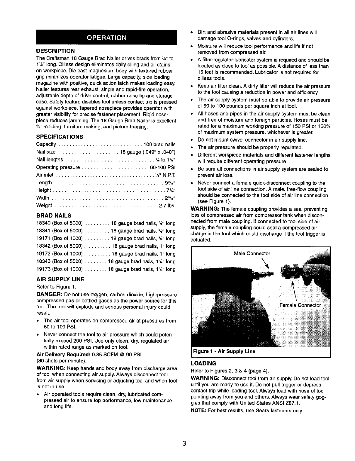
• Never connect a female quick-disconnect coupling to the
tool side of air line connection. A male, free-flow coupling
should be connected to the tool side of air line connection
(see Figure 1).
WARNING= The female coupling provides a seal preventing
loss of compressed air from compressor tank when discon-
nected from male coupling, if connected to tool side of air
supply, the female coupling could seal a compressed air
charge in the tool which could discharge if the tool trigger is
actuated.
.... Male Connector
Figure I - Air Supply Line
LOADING
Refer to Figures 2, 3 & 4 (page 4).
WARNING: Disconnect tool from air supply.Do not load tool
untilyou are ready to use it. Do not pull trigger or depress
contacttrip while loading tool. Always loadwith noseof tool
pointingaway from you and others.Always wear safety gog-
gles that comply with United States ANSI Z87.1.
NOTE: For best results, use Sears fasteners only.
Loading ...
Loading ...
Loading ...