Owner's Manual
ICRAFTSMAN'I
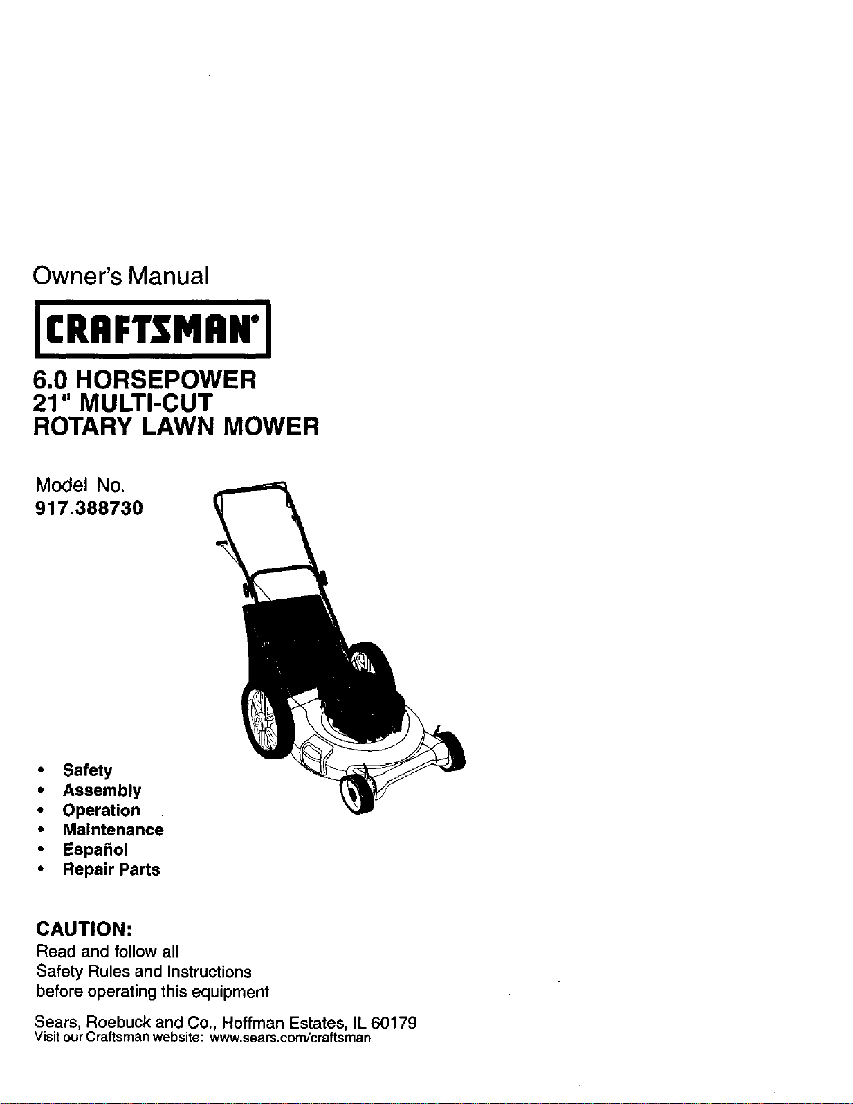
6.0 HORSEPOWER
21" MULTI-CUT
ROTARY LAWN MOWER
Model No.
917.388730
• Safety
• Assembly
• Operation
• Maintenance
• EspaSol
• Repair Parts
CAUTION:
Read and follow all
Safety Rules and Instructions
before operating this equipment
Sears, Roebuck and Co., Hoffman Estates, IL 60179
Visit our Craftsman website: www.sears.com/craftsman
Warranty 2 Product Specifications 11
Safety Rules 2 Service and Adjustments 13
Assembly 5 Storage 14
Operation 6 Troubleshooting 15
Maintenance Schedule 10 Repair Parts 32
Maintenance 10 Parts Ordering Back Cover
LIMITED TWO YEAR WARRANTY ON CRAFTSMAN POWER MOWER
For two years from date of purchase, when this Craftsman Lawn Mower is maintained,
lubricated, and tuned up according to the operating and maintenance instructions in
the owner's manual, Sears will repair free of charge any defect in material or workman-
ship.
If this Craftsman Lawn Mower is used for commercial or rental purposes, this warranty
applies for only 90 days from the date of purchase.
This Warranty does not cover:
• Expendable items which become worn during normal use, such as rotary mower
blades, blade adapters, belts, air cleaners and spark plug.
• Repairs necessary because of operator abuse or negligence, including bent
crankshafts and the failure to maintain the equipment according to the instructions
contained in the owner's manual.
Warranty service is available by returning the Craftsman power mower to the nearest
Sears Service Center/Department in the United States. This warranty applies only
while this product is in use in the United States.
This Warranty gives you specific legal rights, and you may also have other rights which
vary from state to state.
SEARS, ROEBUCK AND CO., D/817 WA, HOFFMAN ESTATES, ILLINOIS 60179
IMPORTANT: This cuttingmachine is capable ofamputatinghandsand feet and
throwingobjects.Failure.toobservethe following safetyinstructionscouldresultin
serious injury or death.
I,GENERAL OPERATION
• Read, understand, and follow all
instructions on the machine and in the
manual(s) before starting. Be thor-
oughly familiar with the controls and the
proper use of the machine before
starting.
• Do not put hands or feet near or under
rotating pads. Keep clear of the
discharge opening at all times.
• Only allow responsible individuals, who
are familiar with the instructions, to
operate the machine.
• Clear the area of objects such as rocks,
toys, wire, bones, sticks, etc., which
could be picked up and thrown by the
blade.
• Be sure the area is clear of other
people before mowing. Stop machine if
anyone enters the area.
2
• Do not operate the mower when
barefoot or wearing open sandals.
Always wear substantial foot wear.
• Do not pull mower backwards unless
absolutely necessary. Always look
down and behind before and while
moving backwards.
• Do not operate the mower without
proper guards, plates, grass catcher or
other safety protective devices in
place.
• See manu!acturer's instructions for
proper operation and installation of
accessories. Only use accessories
approved by the manufacturer.
• Stop the blade(s) when crossing gravel
drives, walks, or roads.
• Stop the engine (motor) whenever you
leave the equipment, before cleaning
the mower or unclogging the chute.
• Shut the engine (motor) off and wait
until the blade comes to complete stop
before removing grass catcher.
• Mow only in daylight or good artificial
light.
• Do not operate the machine while
under the influence of alcohol or drugs.
• Never operate machine in wet grass.
Always be sure of your footing: keep a
firm hold on the handle and walk; never
run.
• Disengage the self-propelled mecha-
nism or drive clutch on mowers so
equipped before starting the engine
(motor).
• If the equipment should start to vibrate
abnormally, stop the engine (motor)
and check immediately for the cause.
Vibration is generally a warning of
trouble.
• Always wear safety goggles or safety
glasses with side shields when
operating mower.
I1.SLOPE OPERATION
Slopes are a major factor related to slip
and fall accidents which can result in
severe injury. All slopes require extra
caution. If you feel uneasy on a slope, do
not mow it.
DO:
• Mow across the face of slopes: never
up and down. Exercise extreme caution
when changing direction on slopes.
• Remove obstacles such as rocks, tree
limbs, etc.
• Watch for holes, ruts, or bumps. Tall
grass can hide obstacles.
DO NOT:
• ' Do not trim near drop-offs, ditches or
embankments. The operator could lose
footing or balance.
• Do not trim excessively steep slopes.
• Do not mow on wet grass. Reduced
footing could cause slipping.
IlLCHILDREN
Tragic accidents can occur if the operator
is not alert to the presence of children.
Children are often attracted to the
machine and the mowing activity. Never
assume that children will remain where
you last saw them.
• Keep children out of the trimming area
and under the watchful care of another
responsible adult.
• Be alert and turn machine off if children
enter the area.
• Before and while walking backwards,
look behind and down for small
children,
• Never allow children to operate the
machine.
• Use extra care when approaching blln¢
corners, shrubs, trees, or other objects
that may obscure vision.
IV. SERVICE
• Use extra care in handling gasoline
and other fuels. They are flammable
and vapors are explosive.
- Use only an approved container.
- Never remove gas cap or add fuel
with the engine running. Allow
engine to cool before refueling. Do
not smoke.
- Never refuel the machine indoors.
- Never store the machine or fuel
container inside where there is an
open flame, such as a water heater.
• Never run a machine inside a closed
area.
• Never make adjustments or repairs witl
the engine (motor) running. Disconnecl
the spark plug wire, and keep the wire
away from the plug to prevent acciden-
tal starting.
• Keep nuts and bolts, especially blade
attachment bolts, tight and keep
equipment in good condition.
• Never tamper with safety devices.
Check their proper operation regulady.
• Keep machine free of grass, leaves, or
other debris build-up. Clean oil or fuel
spillage. Allow machine to cool before
storing.
• Stop and inspect the equipment if you
strike an object. Repair, if necessary,
before restarting.
• Never attempt to make wheal height
adjustments while the engine (motor) i.'
running.
• Grass catcher components are subject
to wear, damage, and deterioration,
which could expose moving parts or
allow objects to be thrown. Frequently
check components and replace with
manufacturer's recommended parts,
when necessary.
• Mower blades are sharp and can cut.
Wrap the blade(s) or wear gloves, and
use extra caution when servicing them
• Do not change the engine governor
setting or overspaed the engine.
3
AILook for thissymboltopointout
importantsafetyprecautions.Itmoans
CAUTIONlll BECOMEALERTI!!YOUR
SAFETYIS INVOLVED.
WARNING: In ordertoprevent
accidentalstartingwhen settingup,
transporting,adjustingor makingrepairs,
alwaysdisconnectsparkplug wireand
place wirewhere itcannotcontactspark
plug.
A,WARNING: Engineexhaust,someofits
constituents,and certainvehiclecompo-
nentscontainor emitchemicalsknownto
the State ofCaliforniato causecancer
and birthdefectsor otherreproductive
harm.
_IWARNING: Batteryposts,terminalsand
relatedaccessoriescontainlead and
lead compounds,chemicalsknownto the
State ofCaliforniatocausecancerand
bidh defectsorotherreproductiveharm.
Wash handsafter handling.
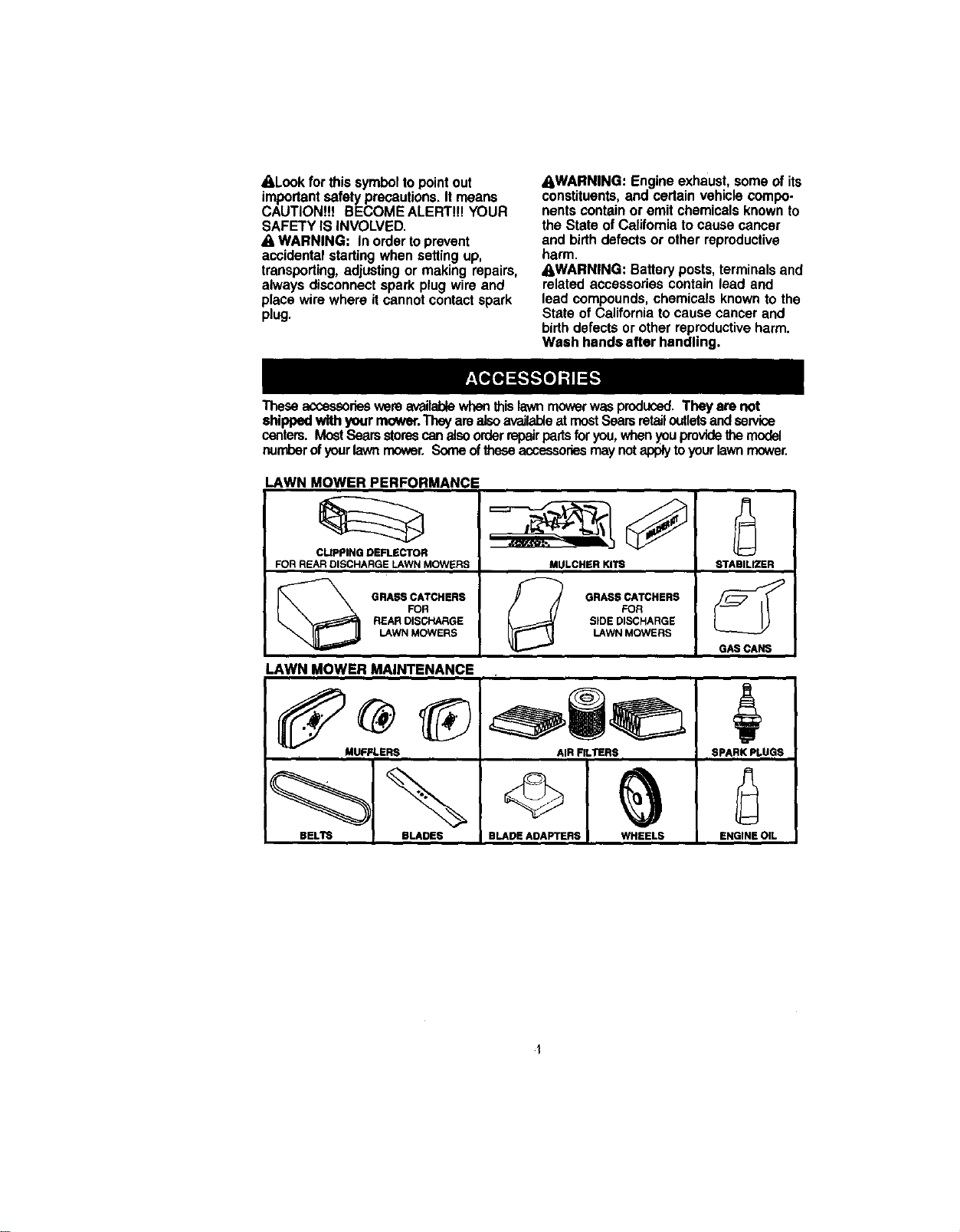
Thoseaccessorieswereavailablewhenthislawnmowerwasproduced.They arenot
shippedwith yourmower.Theyarealsoavailableat mostSearsretailoutletsandservice
centers.MostSearsstorescanalsoorderrepairpartsfor you,when_0uprovidethemodel
numberofyourlawnmower.Someoftheseaccessoriesmaynutapplytoyourlawnmower.
LAWN MOWER PERFORMANCE
CLIPPING DEFLECTOR
FOR REAR DISCHARGE LAWN MOWERS
GRASS CATCHERS
FOR
REARDISGHARGE
LAWN MOWERS
MULCHER KITS
GRASSCATCHERS
FOR
SIDE DIscHARGE
LAWNMOWERS
STABILIZER
GAS CANS
LAWN MOWER MAINTENANCE
MUFFLERS AIR FILTERS SPANK PL.UGS
BELTE BLADES BLADE ADAPTERS WHEELS ENGINE OIL
Read these instructions and this manual
in its entirety before you attempt to
assemble or operate your new lawn
mower.
IMPORTANT: This lawn mower is
shipped WITHOUT OIL OR GASOLINE in
the engine.
Your new lawn mower has been as-
sembled at the factory with the exception
of those parts left unassembled for
shipping purposes. All parts such as nuts,
washers, bolts, etc., necessary to com-
plete the assembly have been placed in
the parts bag. To ensure safe and proper
operation of your lawn mower, all parts
and hardware you assemble must be
tightened securely. Use the correct tools
as necessary to ensure proper tightness.
TO REMOVE LAWN MOWER FROM
CARTON
1. Remove loose parts included with
mower.
2. Cut down two end corners of carton
and lay end panel down flat.
3. Remove all packing materials except
padding between upper and lower
handle and padding holding operator
presence control bar to upper handle.
4. Roll lawn mower out of carton and
check carton thorougly for additional
loose parts.
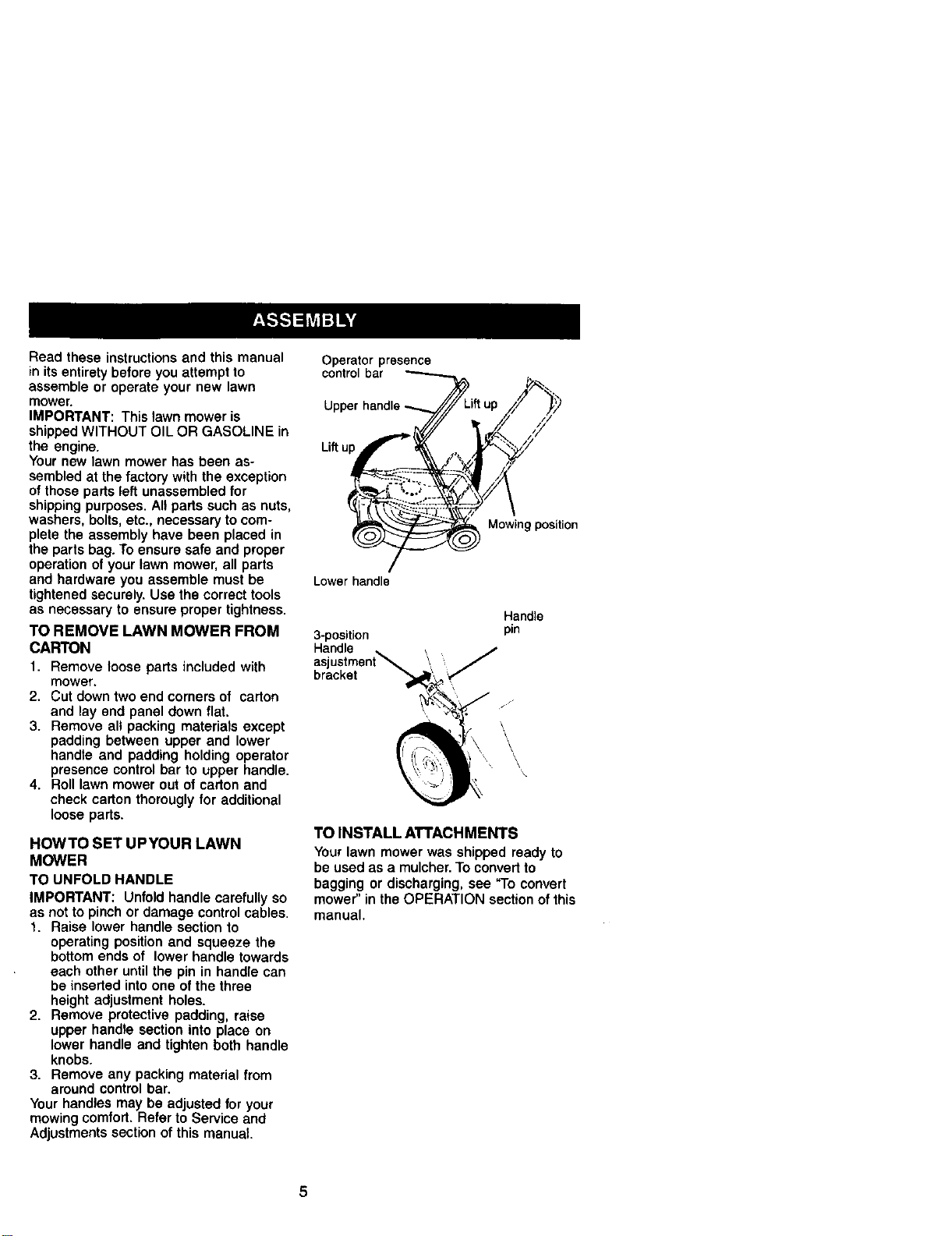
HOWTO SET UPYOUR LAWN
MOWER
TO UNFOLD HANDLE
IMPORTANT: Unfold handle carefully so
as not to pinch or damage control cables.
1. Raise lower handle section to
operating position and squeeze the
bottom ends of lower handle towards
each other until the pin in handle can
be inserted into one of the three
height adjustment holes.
2. Remove protective padding, raise
upper handle section into place on
lower handle and tighten both handle
knobs.
3. Remove any packing material from
around control bar.
Your handles may be adjusted for your
mowing comfort. Refer to Service and
Adjustments section of this manual.
Operator presence
control bar
Upper handle
Mowing position
Lowerhandle
3-position
aslt
bracket
Handle
pin
TO INSTALL ATTACHMENTS
Yourlawn mowerwas shippedreadyto
be usedas a mulcher.To convertto
baggingor discharging,see "To convert
mower" intheOPERATIONsectionofthis
manual.
5
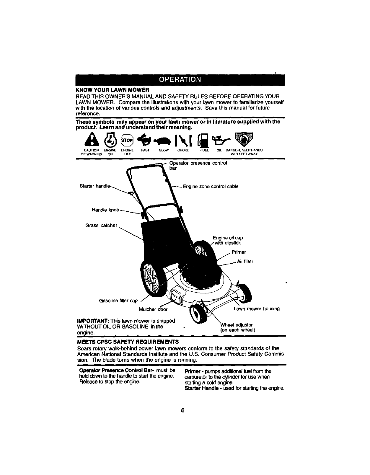
KNOW YOUR LAWN MOWER
READ THIS OWNER'S MANUAL AND SAFETY RULES BEFORE OPERATING YOUR
LAWN MOWER. Compare the illustrations with your lawn mower to familiarize yourself
with the location of various controls and adjustments. Save this manual for future
reference.
These symbols mayappear on your lawn mower or In literature suppliedwith the
product. Learnand understand their meaning.
CAUTK)N ENGINE ENGINE FAST 8LOW CHOKE FUEL OIL DANGER, KEEP HANDS
OR WARNING ON OFF AND FEET AWAY
presence control
bar
zone controlcable
Grass catcher
Engineoilcap
/ withdipstick
Gasolinefillercap
Mulcherdoor Lawnmower housing
IMPORTANT: This lawn mower is shipped
WITHOUT OIL OR GASOLINE inthe
en_line. (on each wheel)
MEETS CPSC SAFETY REQUIREMENTS
Sears rotary walk-behind power lawn mowers conform to the safety standards of the
Amedcan National Standards Institute and the U.S. Consumer Product Safety Commis-
sion. The blade turns when the engine is running.
Operator Presence Control Bar- must be Pdmer - pumps additionalfuel from the
helddown tothe handletostartthe engine, carburetorto the cylinderfor use when
Release to stopthe engine, startinga cold engine.
Starter Handle - usedfor startingthe engine.
6
The operation of any lawn mower can result in foreign objects thrown
into the eyes, which can result in severe eye damage. Always wear
safety glasses or eye shields while operating your lawn mower or
performing any adjustments or repairs. We recommend e wide vision
safety mask over spectacles or standard safety glasses.
HOWTO USEYOUR LAWN MOWER
ENGINE SPEED CONTROL
The engine speed was set at the factory
for optimum performance. Speed is not
adjustable.
ENGINE ZONE CONTROL
_kCAUTION: Federal regulations require
an engine control to be installed on this
lawn mower in order to minimize the risk
of blade contact injury. Do not under any
circumstances attempt to defeat the
function of the operator control. The blade
turns when the engine is running.
• Your lawn mower is equipped with an
operator presence control bar which
requires the operator to be positioned
behind the lawn mower handle to start
and operate the lawn mower.
TO ADJUST CUTTING HEIGHT
Raise wheels for low cut and lower
wheels for high cut, adjust cutting height
to suit your requirements. Medium
position is best for most lawns.
• To change cutting height, squeeze
adjuster lever toward wheel. Move
wheel up or down to suit your require-
ments. Be sure all wheels are in the
same setting.
NOTE: Adjuster is properly positioned
when plate tab inserts into hole in lever.
Also. 9-position adjusters (if so equipped)
allow lever to be positioned between the
plate tabs.
LowerWheelsfor HighCut
Lever
Raise Wheels for LowCut
TO CONVERT MOWER
Your lawn mower was shipped ready to
be used as a mulcher. To convert to
bagging or discharging:
REAR BAGGING
• Lift rear door of the lawn mower and
place the grass catcher frame hooks
onto the door pivot pins.
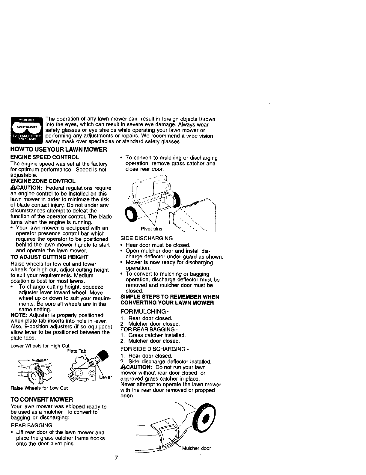
• To convert to mulching or discharging
operation, remove grass catcher and
close rear door.
Pivot pins
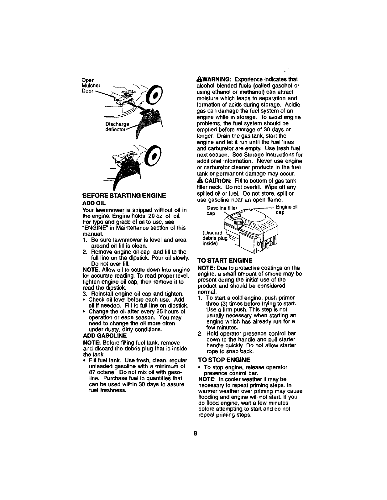
SIDE DISCHARGING
• Rear door must be closed.
• Open mulcher door and install dis-
charge deflector under guard as shown,
• Mower is now ready for discharging
operation.
• To convert to mulching or bagging
operation, discharge deflector must be
removed and mulcher door must be
closed.
SIMPLE STEPS TO REMEMBER WHEN
CONVERTING YOUR LAWN MOWER
FOR MULCHING -
1. Rear door closed.
2. Mulcher door closed.
FOR REAR BAGGING -
1. Grass catcher installed.
2. Mulcher door closed.
FOR SIDE DISCHARGING -
1. Rear door closed.
2. Side discharge deflector installed.
_CAUTION: Do not run your lawn
mower without rear door closed or
approved grass catcher in place.
Never attempt to operate the lawn mower
with the rear door removed or prepped
open.
7
Open
Mulcher
Discharge
BEFORE STARTING ENGINE
ADD OIL
Yourlawnmoweris shippedwithoutoilin
theengine.Engineholds 20 oz.of oil.
Fortypeand gradeof oilto use, see
=ENGINE"in Maintenancesectionofthis
manual.
1. Be sure lawnmoweris level and area
aroundoil fillis clean.
2. Removeengine oilcap end fillto the
fulllineon the dipstick.Pouroilslowly.
Do notoverfill.
NOTE: Allowoilto settledownintoengine
for accuratereading.To read properlevel,
tightenengineoil cap,then removeit to
read thedipstick.
3. Reinstallengine oilcap and tighten.
• Check oillevel beforeeach use. Add
oilifneeded. Filltofulllineon dipstick.
• Changethe oilafterevery25 hoursof
operationor each season. You may
need tochangethe oilmoreoften
underdusty,dirtyconditions.
ADD GASOLINE
NOTE: Beforefilling fuel tank,remove
and discardthe debrisplugthat isinside
the tank.
• Fillfuel tank. Usefresh, clean,regular
unleadedgasolinewith a minimumof
87 octane. Do not mixoilwithgaso-
line. Purchasefuel in quantitiesthat
can be usedwithin30 daysto assure
fuel freshness.
_WARNING: Expedenceindicatesthat
alcoholblendedfuels (calledgasoholor
usingethanolor methanol)can attract
moisturewhichleads to separation and
formation ofacidsduringstorage. Acidic
gascan damagethefuel systemofan
enginewhilein storage. Toavoid engine
problems,thefuel systemshouldbe
emptiedbeforestorageof30 daysor
longer. Drainthegastank,startthe
engineand let itrununtilthe fuel lines
and carburetorareempty. Use freshfuel
nextseason. See StorageInstructionsfor
additionalinformation. Never useengine
or carburetorcleanerproductsinthe fuel
tank orpermanentdamagemay occur.
A CAUTION: Filltobottomofgastank
filler neck. Do notoverfill.Wipeoffany
spilledoilorfuel. Do notstore,spillor
usegasolinenear an openflame.
Gasolinefiller
cap cap
(Discard
debds plug
inside)
TO START ENGINE
NOTE: Due to protectivecoatingson the
engine,a smallamountof smokemay be
presentdudngthe initialuseofthe
productand shouldbe considered
normal.
1. To starta coldengine,pushprimer
three (3) timesbeforetryingtostart.
Usea firm push.Thisstepisnot
usuallynecessarywhen starting an
enginewhichhas alreadyrunfor a
few minutes.
2. Hold operatorpresencecontrolbar
downto the handleand pullstarter
handlequickly.Do not allowstarter
ropetosnap back.
TO STOP ENGINE
• To stopengine, releaseoperator
presencecontrolbar.
NOTE: Incoolerweatheritmaybe
necessaryto repeatpdmingsteps.In
warmerweatherover primingmaycause
flooding andenginewillnot start.Ifyou
do flood engine,waita few minutes
beforeattemptingtostartand do not
repeatprimingsteps.
MOWINGTIPS
• Under certain conditions, such as very
tall grass, it may be necessary to raise
the height of cut to reduce pushing
effort and to keep from overloading the
engine and leaving clumps of grass
clippings. It may also be necessary to
reduce ground speed and/or run the
lawn mower over the area a second
time.
• For extremely heavy cutting, reduce the
width of cut by overlapping previously
cut path and mow slowly.
• For better grass bagging and most
cutting conditions, the engine speed
should be set in the fast position.
• Pores in cloth grass catchers can
become filled with dirt and dust with
use and catchers will collect less grass.
To prevent this, regularly hose catcher
off with water and let dry before using.
• Keep top of engine around starter clear
and clean of grass clippings and chaff.
This will help engine air flow and
extend engine life.
MULCHING MOWINGTIPS
IMPORTANT: For best performance,
keep mower housing free of built-up
grass and trash. See "Cleaning" in
MAINTENANCE section of this manual.
• The special mulching blade will recur
the grass clippings many times and
reduce them in size so that as they fall
onto the lawn they will disperse into the
grass and not be noticed, Also, the
mulched grass will biodegrade quickly
to provide nutrients for the lawn.
Always mulch with your highest engine
(blade) speed as this will provide the
best recutting action of the blades.
• Avoid cutting your lawn when it is wet.
Wet grass tends to form clumps and
interferes with the mulching action. The
best time to mow your lawn is the early
afternoon. At this time the grass has
dried and the newly cut area will not be
exposed to the direct sun.
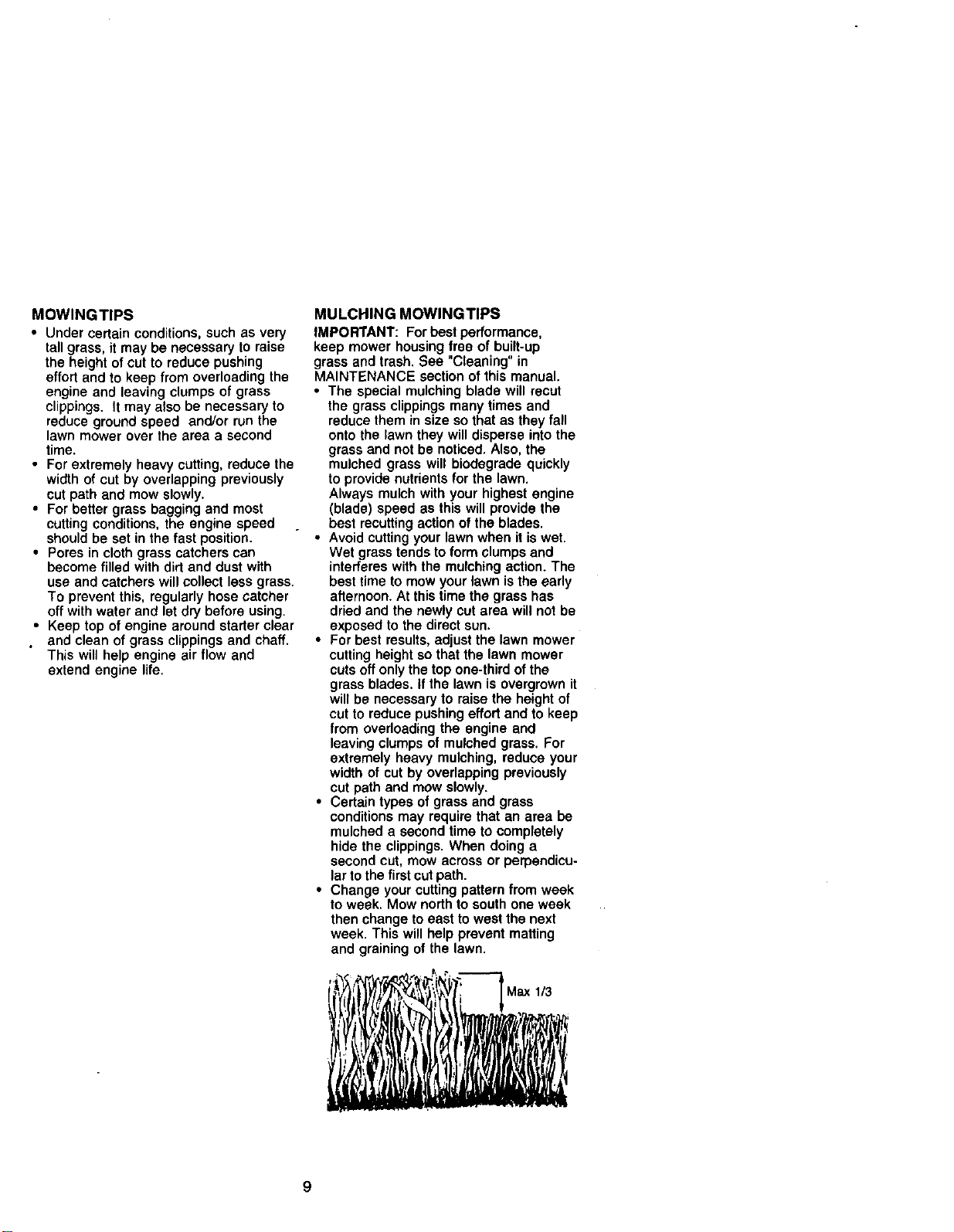
• For best results, adjust the lawn mower
cutting height so that the lawn mower
cuts off only the top one-third of the
grass blades, if the lawn is overgrown it
will be necessary to raise the height of
cut to reduce pushing effort and to keep
from overloading the engine and
leaving clumps of mulched grass. For
extremely heavy mulching, reduce your
width of cut by overlapping previously
cut path and mow slowly.
• Certain types of grass and grass
conditions may require that an area be
mulched a second time to completely
hide the clippings. When doing a
second cut, mow across or perpendicu-
lar to the first cut path.
• Change your cutting pattern from week
to week. Mow north to south one week
then change to east to west the next
week. This will help prevent matting
and graining of the lawn.
i
Max 113
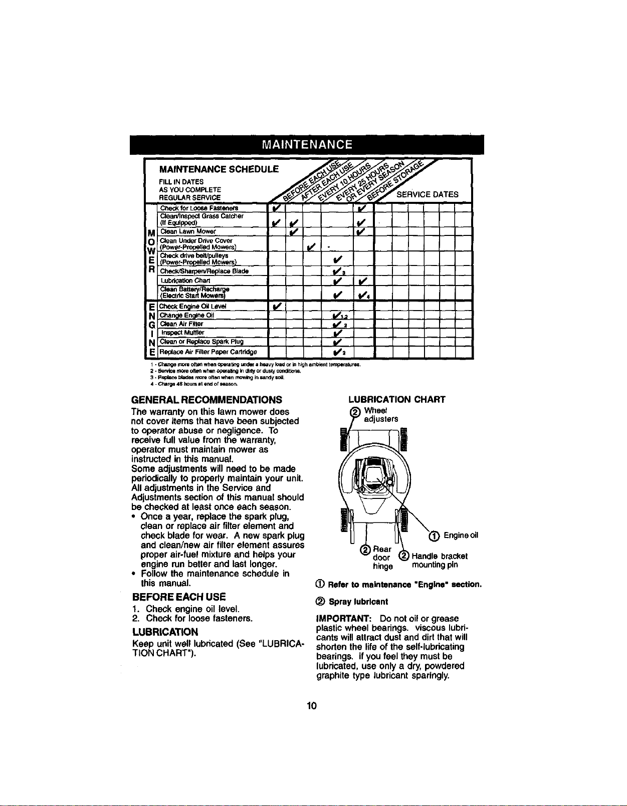
MA,NTENA.CESCHEDULE
forLOO_ Fasteners _1_
Clea_/EnspsctGrass Catcher
(. Equipped) I/ iv' I/
M CleanLawnMower ll/
Clean Under Drive Cover
IPower-Prop_[ed Mowers)
ddve belt/pulleys
E (Power-Propelled Mowers} I/
_r_VRop=ace Blade t/_
Clean BaSeP//Recha
E CheckEngineONLeVe_
a cl_angeEnglneOil I_/1.2
G Clean _r Fitter i/=
I InspectMuffler i/
N CleanorReplac_SparkPlug
E Replace Air Filter P=der C=rtridge il_=
1 - Cha_e rno_ oft_ when operatingut_4_-a P_aW Io_ or in higha_',blenttemp_affir _
2 - Sswice r_re oft_ when opt-sling Indirtyor dustycondl6c_s,
3 - Replacetdadesmore oft_ when mowl_ in_ndy =c_J.
4 - Chaise 48 hoursat ewJof season.
GENERAL RECOMMENDATIONS
The warrantyon thislawn mowerdoes
notcover itemsthat havebeen subjected
to operatorabuse or negligence.To
receivefull value from the warranty,
operatormustmaintainmower as
instructedin this manual.
Someadjustmentswillneed to be made
periodicallytoproperlymaintainyourunit.
Alladjustmentsin theService and
Adjustmentssectionofthis manualshould
be checkedat leastonce each season.
• Once a year, replacethe sparkplug,
clean or replaceair filterelementand
check bladefor wear. A new sparkplug
and clean/new air filter element assures
properair-fuelmixtureand helpsyour
engine runbetterand last longer.
• Followthe maintenanceschedule in
this manual.
BEFORE EACH USE
1. Check engine oil level,
2. Check forloosefasteners.
LUBRICATION
Keep unit well lubricated (See "LUBRICA-
TION CHART").
LUBRICATION CHART
Wheet
adjusters
I
!_ Engineoil
Handle bracket
hinge mountingpin
(_ Refer to maintenance "Engine" section.
_) Spray lubricant
IMPORTANT: Do not oil or grease
plastic wheel bearings, viscous lubri-
cants will attract dust and dirt that will
shorten the life of the self-lubricating
bearings, if you feel they must be
lubricated, use only a dry, powdered
graphite type lubricant sparingly.
lO
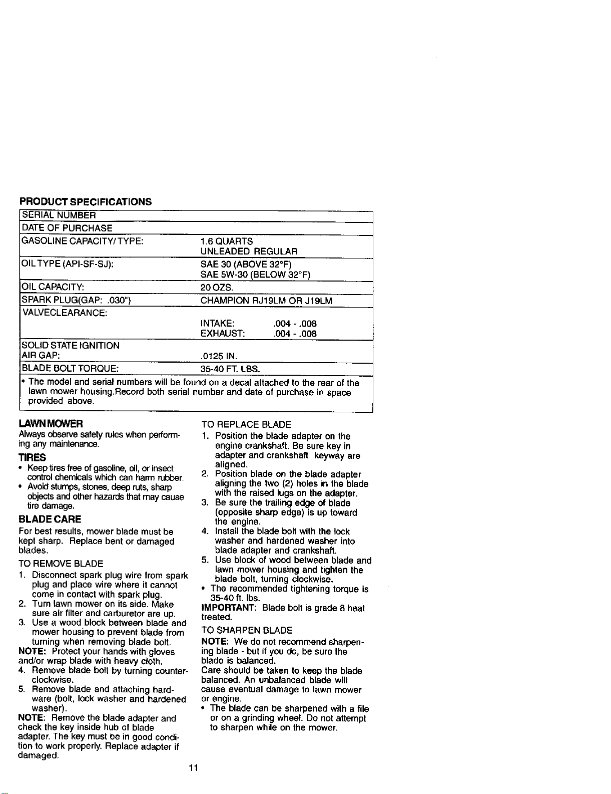
PRODUCT SPECIFICATIONS
SERIAL NUMBER
DATE OF PURCHASE
GASOLINE CAPACITY/TYPE: 16 QUARTS
UNLEADED REGULAR
OILTYPE (API-SF-SJ): SAE 30 (ABOVE 32°F)
SAE 5W-30 (BELOW 32°F)
OIL CAPACITY: 20 OZS.
SPARK PLUG(GAP: .030") CHAMPION RJ19LM OR JI9LM
VALVECLEARANCE:
INTAKE: .004 - .008
EXHAUST: .004 - .008
SOLID STATE IGNITION
AIR GAP: .0125 IN.
BLADE BOLT TORQUE: 35-40 FT. LBS.
• The model and serial numbers will be found on a decal attached to the rear of the
lawn mower housing.Record both serial number and date of purchase in space
provided above.
LAWN MOWER
Always observe safety ruleswhen perform-
ing any maintenance.
TIRES
• Keep tiresfree ofgasoline,oil,or insect
controlchemicalswhichcan harm rubber.
• Avoidstumps,stones,deep ruts,sharp
objectsand other h_ards thatmay cause
tiredamage.
BLADE CARE
For best results, mower blade must be
kept sharp. Replace bent or damaged
blades.
TO REMOVE BLADE
1, Disconnect spark plug wire from spark
plug and place wire where it cannot
come in contact with spark plug.
2, Turn _awn mower on its side. Make
sure air filter and carburetor are up.
3. Use a wood block between blade and
mower housing to prevent blade from
turning when removing blade bolt.
NOTE: Protect your hands with gloves
and/or wrap blade with heavy cloth.
4. Remove blade bolt by turning counter-
clockwise.
5. Remove blade and attaching hard-
ware (bolt, lock washer and hardened
washer).
NOTE: Remove the blade adapter and
check the key inside hub of blade
adapter. The key must be in good condi-
tion to work properly. Replace adapter if
damaged.
TO REPLACE BLADE
1. Position the blade adapter on the
engine crankshaft. Be sure key in
adapter and crankshaft keyway are
aligned.
2. Position blade on the blade adapter
aligning the two (2) holes in the blade
with the raised lugs on the adapter.
3. Be sure the trailing edge of blade
(opposite sharp edge) is up toward
the engine.
4. Install the blade bolt with the lock
washer and hardened washer into
blade adapter and crankshaft.
5. Use block of wood between blade and
lawn mower housing and tighten the
blade bolt, turning clockwise.
• The recommended tightening torque is
35-40 ft. Ibs.
IMPORTANT: Blade bolt is grade 8 heat
treated.
TO SHARPEN BLADE
NOTE: We do not recommend sharpen-
ing blade - but if you do, be sure the
blade is balanced.
Care should be taken to keep the blade
balanced. An unbalanced blade will
cause eventual damage to lawn mower
or engine.
• The blade can be sharpened with a file
or on a grinding wheel. Do not attempt
to sharpen while on the mower.
1!
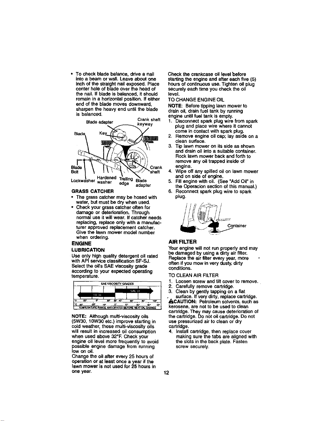
• To check blade balance, drive a nail
into a beam or wall. Leave about one
inch of the straight nail exposed. Place
center hole of blade over the head of
the nail. If blade is balanced, it should
remain in a horizontal position. If either
end of the blade moves downward,
sharpen the heavy end until the blade
is balanced.
Btadeadapter Crank shaft
Blad_ Key_ (r_'_'_
, -.._..2:2
k
\ I \ \ •\ ' _/ "shaft
jsrdened T_railir _,_.,_
Lockw _her washer '._'"" Blade
eoge adapter
GRASS CATCHER
• The grass catcher may be hosed with
water, but must be dry when used.
• Check your grass catcher often for
damage or deterioration. Through
normal use it will wear. If catcher needs
replacing, replace only with a manufac-
turer approved replacement catcher.
Give the lawn mower model number
when ordering.
ENGINE
LUBRICATION
Use only high quality detergent oil rated
with API service classification SF-SJ.
Select the oil's SAE viscosity grade
according to your expected operating
temperature.
SAEVISCOSITY GRADES
NOTE: Although multi-viscosity oils
(5W30, 10W30 etc.) improve starting in
cold weather, these multi-viscosity oils
will result in increased oil consumption
when used above 32°E Check your
engine oil level more frequently to avoid
possible engine damage from running
low on oil.
Change the oil after every 25 hours of
operation or at least once a year if the
lawn mower is not used for 25 hours in
one year,
Check thecrankcaseoillevelbefore
startingthe engineand aftereachfive(5)
hoursofcontinuoususe.Tightenoilplug
securelyeachtimeyou checkthe oil
level.
TO CHANGE ENGINE OIL
NOTE: Beforetippinglawnmowerto
drainoil, drainfuel tankby running
engineuntilfuel tank isempty.
1. Disconnectsparkplugwirefrom spark
plugand placewire whereit cannot
comein contactwithsparkplug.
2. Removeengineoilcap;lay asideon a
clean sudace.
3. Tip lawn moweron itsside as shown
and drainoil intoa suitablecontainer.
Rocklawnmowerbackand forth to
removeanyoiltrappedinsideof
engine.
4. Wipe offany spilledoilon lawn mower
and on side of engine.
5. Fillenginewithoil. (See "Add Oil"in
the Operacionsectionofthis manual.)
6. Reconnectsparkplugwireto spark
plug.
__ntainer
AIR FILTER
Yourenginewillnot runproperlyand may
be damagedby usinga dirtyairfilter.
Replacethe air filtereveryyear, more
oftenifyoumow inverydusty,dirty
conditions.
TO CLEANAIR FILTER
1, Loosenscrew andtiltcoverto remove.
2. Carefullyremove cartridge.
3. Cleanby gentlytappingon a flat
surface.Ifverydirty,replacecadridge.
"_.CAUTION: Petroleumsolvents,suchas
kerosene, are nottobe used toclean
cartridge.They may causedeteriorationof
the cartridge,Do notoilcartridge.Do not
usepressurizedair to cleanor dry
cartridge.
4. Installcartridge,then replacecover
makingsurethe tabsare alignedwith
the slotsinthe backplate. Fasten
screwsecurely.
12
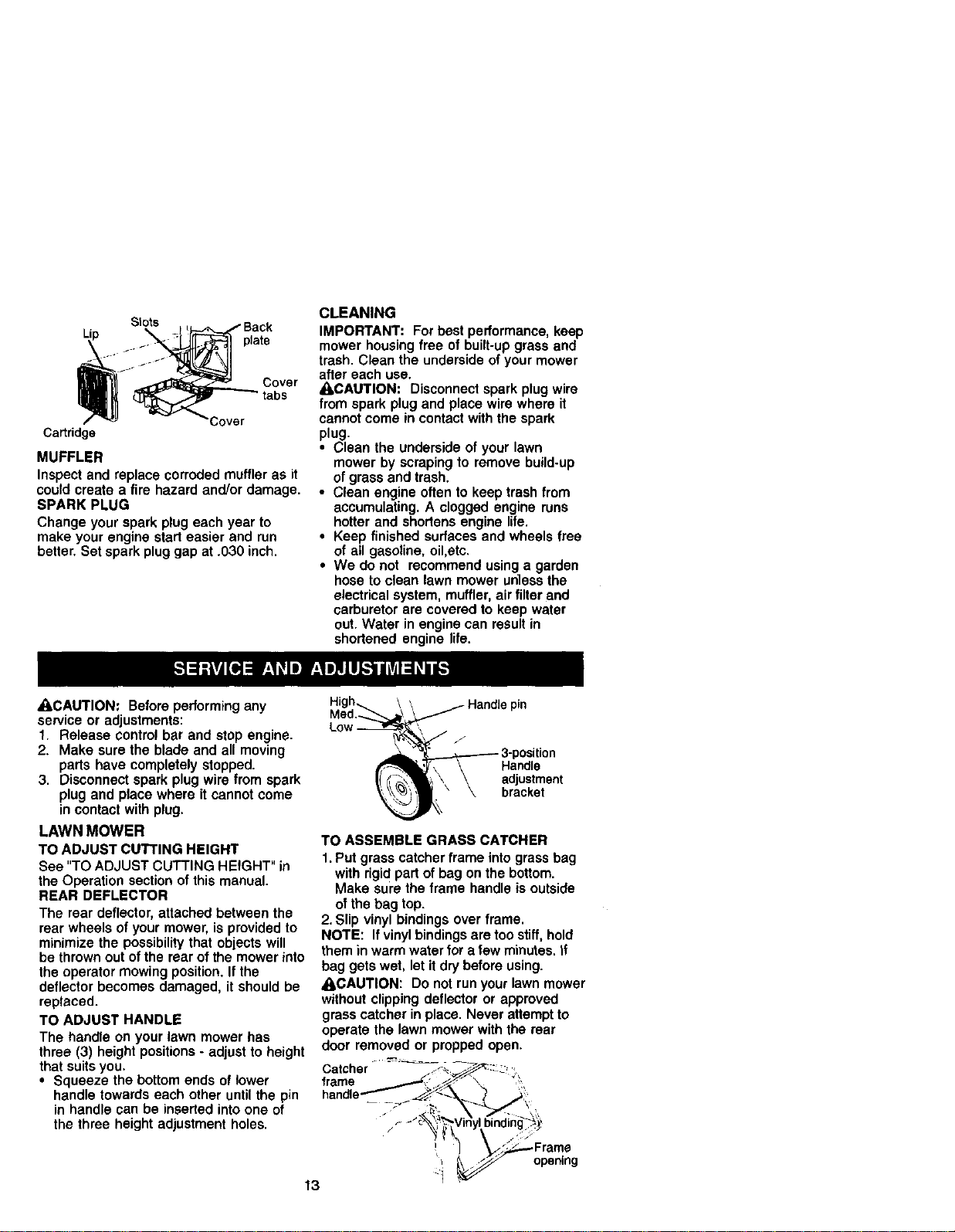
Stots
plate
Cover
tabs
Cover
Ca_ridge
MUFFLER
Inspect and replace corroded muffler as it
could create a fire hazard and/or damage.
SPARK PLUG
Change your spark plug each year to
make your engine start easier and run
better. Set spark plug gap at .030 inch.
CLEANING
IMPOFrI'ANT: For best performance, keep
mower housing free of built-up grass and
trash. Clean the underside of your mower
after each use.
_kCAUTION: Disconnect spark plug wire
from spark plug and place wire where it
cannot come in contact with the spark
plug.
• Clean the underside of your lawn
mower by scraping to remove build-up
of grass and trash.
• Clean engine often to keep trash from
accumulating. A clogged engine runs
hotter and shortens engine life.
• Keep finished surfaces and wheels free
of atl gasoline, oil,etc.
• We do not recommend using a garden
hose to clean lawn mower untess the
electrical system, muffler, air filter and
carburetor are covered to keep water
out. Water in engine can result in
shortened engine life.
_I,CAUTION: Before performing any
service or adjustments:
1. Release control bar and stop engine.
2. Make sure the blade and all moving
parts have completely stopped.
3. Disconnect spark plug wire from spark
plug and place where it cannot come
in contact with plug.
LAWN MOWER
TO ADJUST CUTTING HEIGHT
See "TO ADJUST CUTTING HEIGHT" in
the Operation section of this manual.
REAR DEFLECTOR
The rear deflector, attached between the
rear wheels of your mower, is provided to
minimize the possibility that objects will
be thrown out of the rear of the mower into
the operator mowing position. If the
deflector becomes damaged, it should be
replaced.
TO ADJUST HANDLE
The handle on your lawn mower has
three (3) height positions - adjust to height
that suits you.
• Squeeze the bottom ends of lower
handle towards each other until the pin
in handle can be inserted into one of
the three height adjustment holes.
High,__
Med._---,,_
Low ]w,=
_ _Handie pin
\ _.
_ 3-position
_\ \ Handle
I! \ \ adjustment
)_' \ bracket
TO ASSEMBLE GRASS CATCHER
1. Put grass catcher frame into grass bag
with rigid part of bag on the bottom.
Make sure the frame handle is outside
of the bag top.
2. Slip vinyl bindings over frame.
NOTE: If vinyl bindings are too stiff, hold
them in warm water for a few minutes, tf
bag gets wet, let it dry before using.
ACAUTION: Do not run your lawn mower
without clipping deflector or approved
grass catcher in place. Never attempt to
operate the lawn mower with the rear
door removed or propped open.
Catcher " - ,_-_ _-'_.-'_::: _'
frame
- -"_ :_V ny bnd ng;:!,
, -" " opening
13
ENGINE
ENGINE SPEED
Your engine speed has been factory set.
Do not attempt to increase engine speed
or it may result in personal injury. If you
believe that the engine is running too fast
or too slow, take your lawn mower to a
Sears or other qualified service center for
repair and adjustment.
CARBURETOR
Your carburetor is not adjustable. If your
engine does not operate properly due to
suspected carburetor problems, take your
lawn mower to a Sears or other qualified
service center for repair and/or adjust-
ment.
IMPORTANT: Never tamper with the
engine governor, which is factory set for
proper engine speed. Overspeeding the
engine above the factory high speed
setting can be dangerous. If you think the
engine-governed high speed needs
adjusting, contact a Sears or other
qualified service center, which has
proper equipment and experience to
make any necessary adjustments.
Immediately prepare your lawn mower for
storage at the end of the season or if the
unitwill not be used for 30 days or more.
LAWN MOWER
When lawn mower is to be stored for a
period of time, clean it thoroughly, remove
all dirt, grease, leaves, etc. Store in a
clean, dry area.
1. Clean entire lawn mower (See
"CLEANING" in the Maintenance
section of this manual).
2. Lubricate as shown in the Mainte-
nance section of this manual.
3. Be sure that all nuts, bolts, screws,
and pins are securely fastened.
Inspect moving paris for damage,
breakage and wear. Replace if
necessary.
4. Touch up all rusted or chipped paint
surfaces; sand lightly before painting.
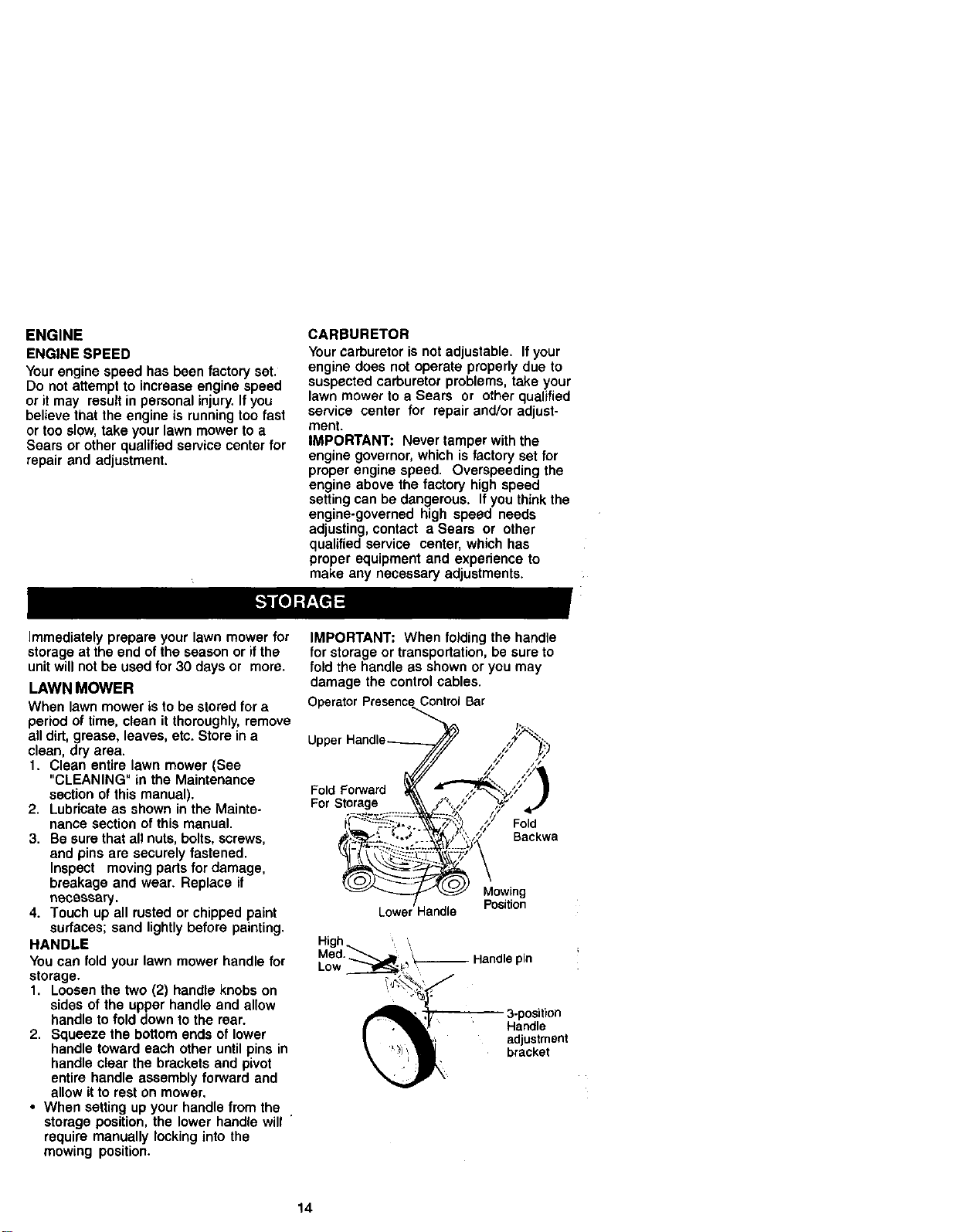
HANDLE
You can fold your lawn mower handle for
storage.
1. Loosen the two (2) handle knobs on
sides of the upper handle and allow
handle to fold down to the rear.
2. Squeeze the bottom ends of lower
handle toward each other until pins in
handle clear the brackets and pivot
entire handle assembly forward and
allow it to rest on mower.
• When setting up your handle from the
storage position, the lower handle will "
require manually locking into the
mowing position.
IMPORTANT: When folding the handle
for storage or transportation, be sure to
fold the handle as shown or you may
damage the control cables.
OperatorPresenceControl Bar
Uppe,
Fold Forward
For Storage
Fold
Backwa
Mowing
LOWE Handle Position
High, ' \
Med. pin
Low
3-portion
Handle
adjustment
bracket
14
ENGINE
FUELSYSTEM
IMPORTANT:It is important to prevent
gum deposits from forming in essential
fuel system parts such as carburetor, fuel
filter,fuel hose, or tank during storage.
Also, experience indicates that alcohol
blended fuels (called gasohol or using
ethanol or methanol) can attract moisture
which leads to separation and formation
of acids during storage. Acidic gas can
damage the fuel system of an engine
while in storage.
1. Drain the fuel tank.
2, Start the engine and let it run until the
fuel tines and carburetor are empty.
• Never use engine or carburetor cleaner
products in the fuel tank or permanent
damage may occur.
• Use fresh fue_ next season.
NOTE: Fuel stabilizer is an acceptable
alternative in minimizing the formation of
fuel gum deposits during storage. Add
stabilizer to gasoline in fuel tank or
storage container. Always follow the mix
ratio found on stabilizer container. Run
engine at least f0 minutes after adding
stabilizer to allow the stabilizer to reach
the carburetor. Do not drain the gas tank
and carburetor if using fuel stabilizer.
ENGINEOIL
Drain oil (with engine warm) and replace
with clean engine oil. (See "ENGINE" in
the Maintenance section of this manual).
CYLINDER
1. Remove spark plug.
2. Pour one ounce (29 ml) of oil through
spark plug hole into cylinder.
3. Pull starter handle slowly a few times
to distribute oil.
4. Replace with new spark plug.
OTHER
• Do not store gasoline from one
season to another.
• Replace your gasoline can if your
can starts to rust. Rust and/or dirt in
your gasoline will cause problems.
• If possible, store your unit indoors
and cover it to give protection from
dust and dirt.
• Cover your unit with a suitable
protective cover that does not retain
moisture. Do not use plastic. Plastic
cannot breathe which allows conden-
sation to form and will cause your unit
to rust.
IMPORTANT: Never cover mower while
engone and exhaust areas are still
warm.
_, CAUTION:Never store the lawn
mower with gasoline in the tank inside
a building where fumes may reach an
open flame or spark. Allow the engine
to cool before storing in any enclosure.
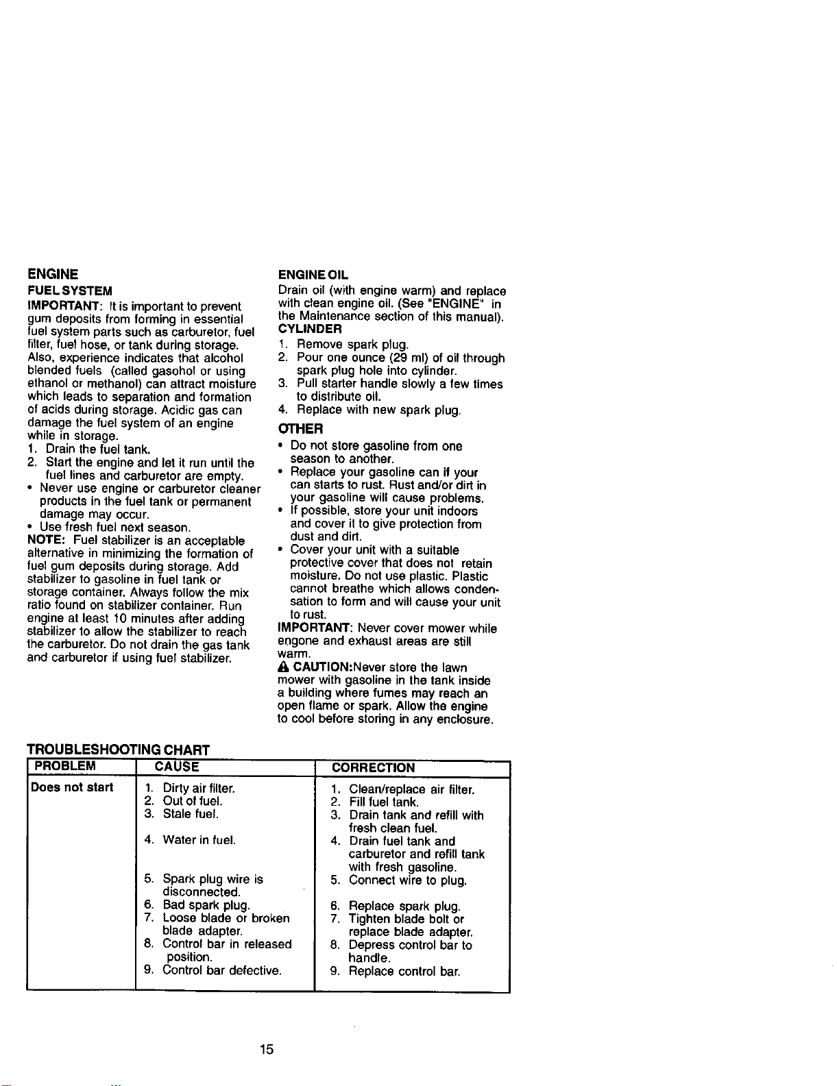
TROUBLESHOOTING CHART
PROBLEM CAUSE
Does not start 1. Dirty air filter.
2. Out of fuel.
3. Stale fuel.
4. Water in fuel.
5. Spark plug wire is
disconnected.
6. Bad spark plug.
7. Loose blade or broken
blade adapter.
8. Control bar in released
position.
9. Control bar defective.
CORRECTION
1. Clean/replace air filter.
2. Fill fuel tank.
3. Drain tank and refill with
fresh clean fuel.
4. Drain fuel tank and
carburetor and refill tank
with fresh gasoline.
5. Connect wire to plug.
6. Replace spark plug.
7. Tighten blade bolt or
replace blade adapter.
8. Depress control bar to
handle.
9. Replace control bar.
15
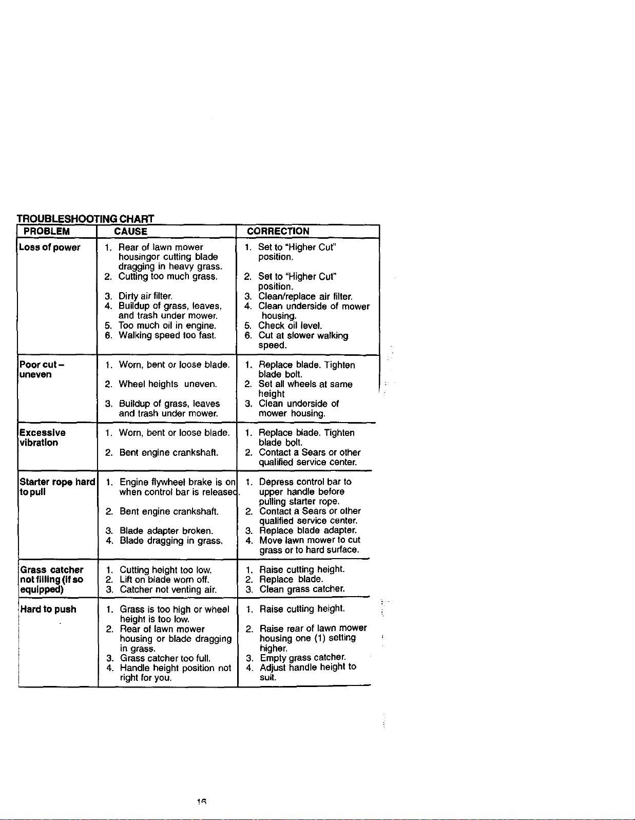
TROUBLESHOOTINGCHART
PROBLEM CAUSE
Lossofpower 1. Rearoflawnmower
Poor cut -
uneven
CORRECTION
1. Set to "Higher Cut"
position.
2. Set to "Higher Cut"
position,
3. Clean/replace air filter.
4. Clean undersideof mower
housing.
5. Check oil level.
6. Cutat slowerwalking
speed.
1. Replace blade. Tighten
blade bolt.
2. Set all wheels at same
height
3. Clean underside of
mower housing.
housingor cutting blade
dragging in heavy grass.
2. Cutting too much grass.
3. Dirty air filter.
4. Buildup of grass, leaves,
and trash under mower.
5. Too much oil in engine.
6. Walking speed too fast.
1. Worn, bent or loose blade.
2. Wheel heights uneven.
3. Buildup of grass, leaves
and trash under mower.
1. Worn, bent or loose blade.
2. Bent engine crankshaft.
t. Engine flywheel brake is or
when control bar is releaseq
2. Bent engine crankshaft.
3. Blade adapter broken.
4. Blade dragging in grass.
1. Cutting height too low.
2. Lifton blade worn off.
3. Catcher not venting air.
I. Grass is too high or wheel
height is too low.
2. Rear of lawn mower
housing or blade dragging
in grass.
3. Grass catcher too full.
4. Handle height position not
right for you.
Excessive 1. Replaceblade.Tighten
vibration blade bolt.
2. Contacta Searsor other
qualifiedservicecenter.
Starter rope hard
topull
t. Depress controlbar to
upper handle before
pullingstarter rope.
2. Contacta Searsor other
qualifiedservicecenter.
3. Replaceblade adapter.
4. Movelawn mowerto cut
grassorto hardsurface.
Grass catcher 1. Raise cuttingheight.
notfilling(Ifso 2. Replace blade.
equipped) 3. Cleangrasscatcher.
Hardto push
t. Raise cutting height.
2. Raise rear of lawn mower
housing one (1) setting
higher.
3. Empty grass catcher.
4. Adjust handle height to
suit.
67
\.
39 40
56
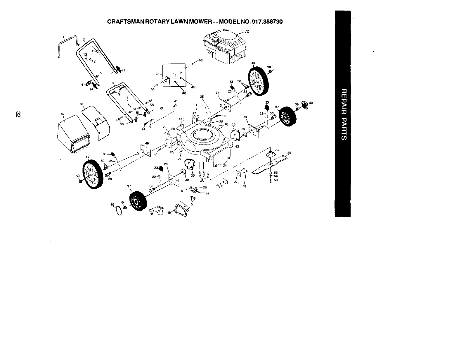
KEY PART
NO. NO.
1 1316_6
2 166860)(479
3 161105)(479
4 132001
5 63601
6 131959
7 66426
8 74780512
9 154132
10 165754
11 162778
12 750097
13 86899X004
14 136376
15 5179_3
16 147286
17 165946X479
19 176(304(36
19 167132X004
20 16713,3X004
21 165858
22 t68360X004
23 166875
24 751153
25 166236)(479
26 166243)(479
27 851856
28 152124
29 160835X007
30 19112222
31 165760
33 87877
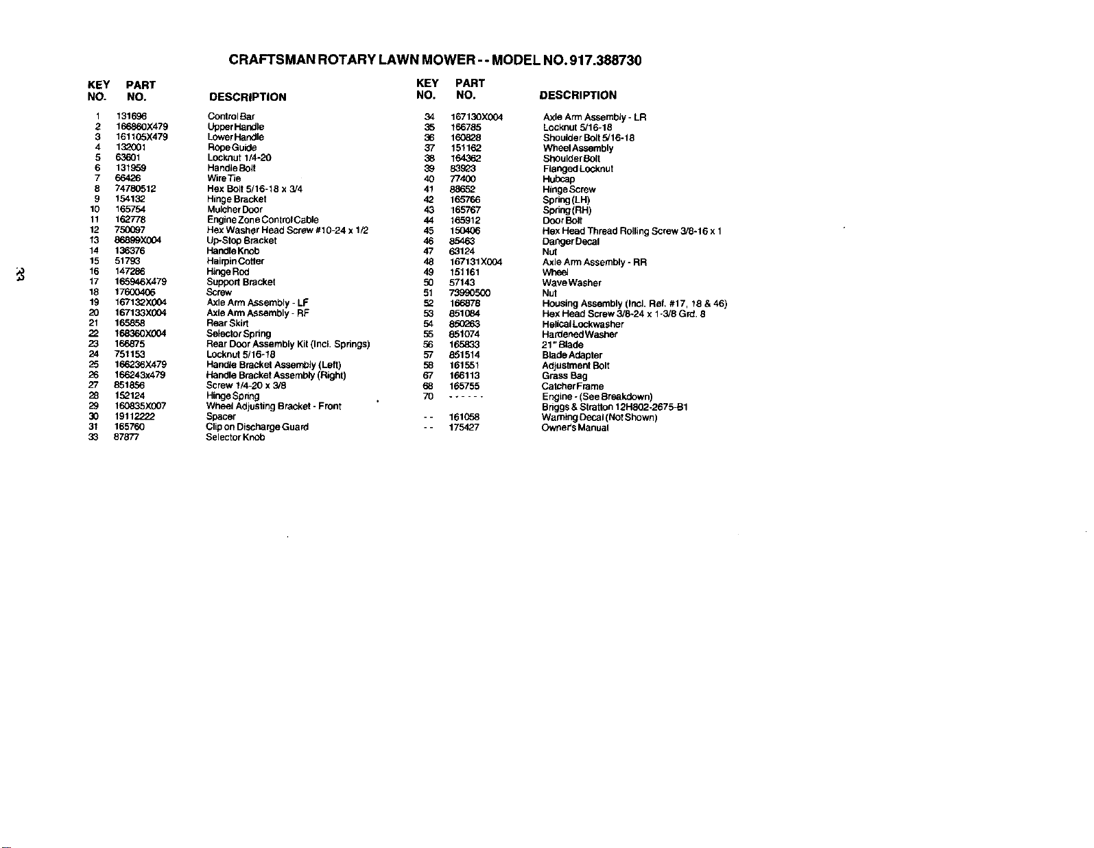
CRAFTSMAN ROTARY LAWN MOWER - - MODEL NO. 917.388730
KEY PART
DESCRIPTION NO. NO. DESCRIPTION
ControlBar 34 167130xG04
Upper Handle 35 166785
Lower Handle 36 160828
RopeGuide 37 151162
Lock,nut 1/4-20 38 164362
HandleBolt 39 83923
WireTie 40 77400
Hex Bolt 5/16-18 x 3/4 41 88652
Hinge Bracket 42 165766
Mulcher Door 43 165767
EngineZoneControlCable 44 165912
Hex Washer Head Screw #10-24 x 1/2 45 150406
Up-St_o Bracket 46 85463
Handle Knob 47 63124
Hairpin Cotler 48 167131X004
Hinge Rod 49 151161
Support Bracket 50 57143
Screw 51 73990500
Axle Arm Assembly - LF 52 166878
Axle Arm Assembly - RF 53 851684
Rear Skill 54
Selector Spring 55 851074
Rear Door Assembly Kil (Incl. Springs) 56 16.5833
Locknut 5/16-18 57 851514
Handle Bracket Assem_bly (Left) 58 161551
Handle Bracket Assembty (Right) 67 166113
Screw 1/4-20 x 3/8 68 1_5755
Hinge Spring 70 ......
Wheet Adjusting Bracket - Front
Spacer - - 161658
Cfip on Discharge Guard - - 175427
Selector Knob
Axle Arm Assembly - LR
Locknut 5/16-18
Shoulder Bolt 5/16-18
Wheel Assembly
ShOulder 8olt
Ranged Locknut
Hubcap
Hinge Screw
Spring (LH)
Spdng(RH)
Door Bolt
Hex Head Thread Rolling Screw 3/8-16 x 1
Danger Decal
Nut
Axle Arm Assembly - RR
Whee_
WaveWasher
Nut
Housing Assembly (IncL Ref. #17, 18 & 46)
Hex Head Screw 3/8-24 x 1-3/8 Grd. 8
HeliCal Lockwasher
Hardened Washer
21" Blade
BladeAdapter
Adjustment Bolt
Grass Bag
CatcherFrame
Engine -(See Breakdown)
Briggs & Stratton 12HSO2-2675-B1
Warning Decal (Not Shown)
Owner's Manual
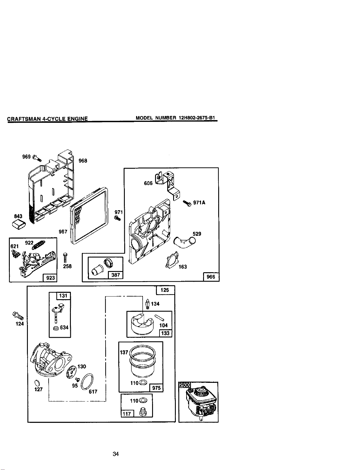
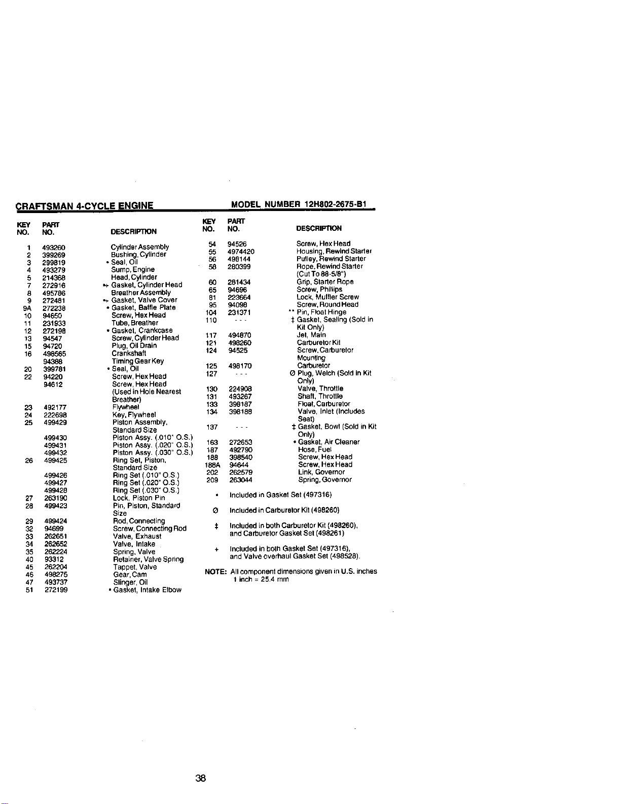
CRA_SMAN 4-CYCLE ENGINE
MODEL NUMBER 12H802-2675-B1
969 _ 968
967 _/
1_27
2_58
130
95
%
124
_634!
i
_I_971A
529
_163
6134
110_ 91-'_'_"
110(_ ]
34
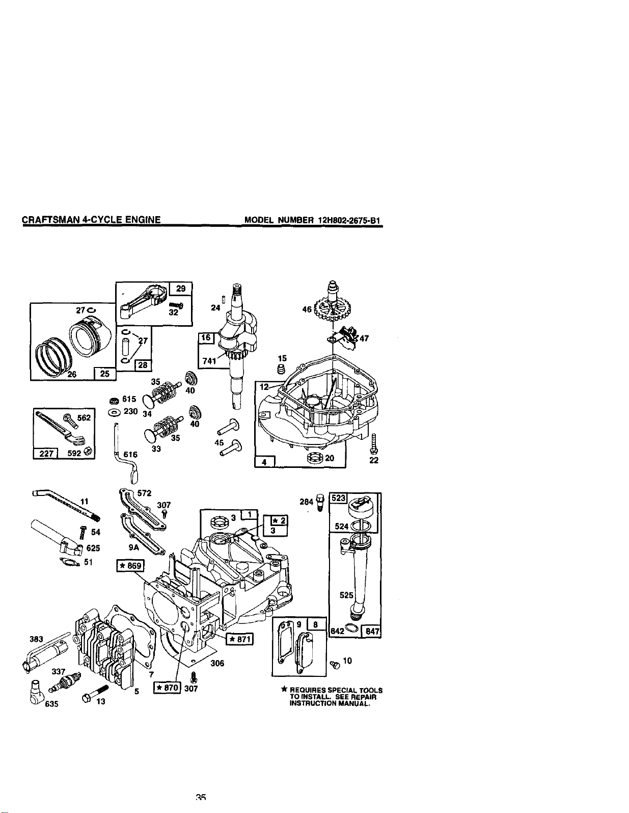
CRAFTSMAN 4-CYCLE ENGINE
MODEL NUMBER 12N802-2675-B1
Q615 _40
_230 34
I 33
24 [ _ 46_
4--I _2o 22
307
383
306
3O7
lk REQUIRES SPECIAL TOOLS
TO INSTALL. SEE REPAIR
INSTRUCTION MANUAL.
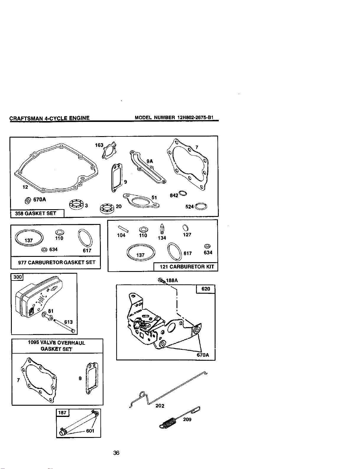
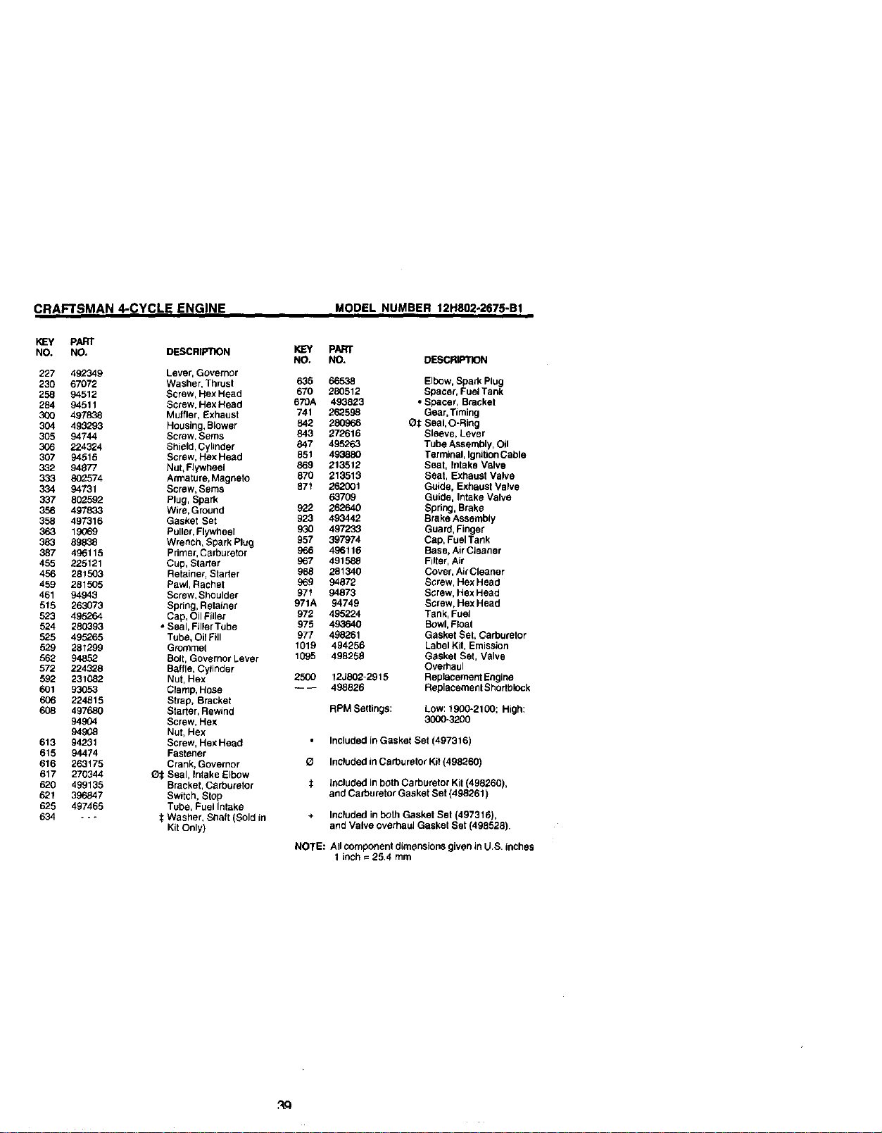
CRAFTSMAN 4-CYCLE ENGINE MODEL NUMBER 12H802-2675-B1
_) 670A _ 3
358 GASKET SET ]
634 617
977 CARBURETOR GASKET SET
613
1095 VALVE OVERHAUL
GASKET SET
104 110 134 127
121 CARBURETOR KIT
@
634
_188A
670A
36
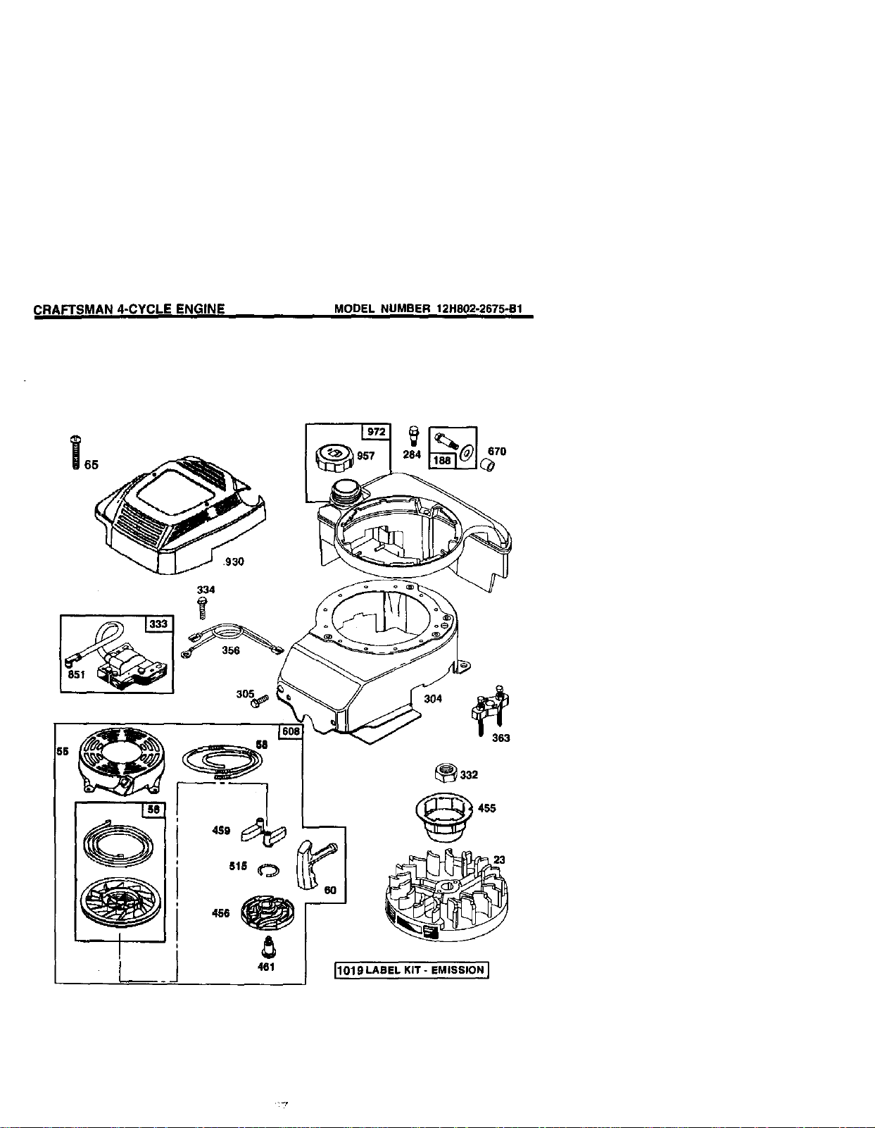
CRAFTSMAN 4-CYCLE ENGINE
MODEL NUMBER 12H802-2675-B1
930
334
_332
I
!
CRAFTSMAN 4-CYCLE ENGINE
KEY PARr
NO. NO. DESCRIPTION
1 493260
2 399269
3 299819
4 493279
5 214368
7 272916
8 495786
9 272481
9A 272238
10 94650
11 231933
12 272198
13 94547
15 94720
16 498565
94388
20 399781
22 94220
94612
23 492177
24 222698
25 499429
499430
499431
499432
26 499425
499426
499427
499428
27 263190
28 499423
29 499424
32 94699
33 262651
34 262652
35 262224
40 93312
45 262204
46 498275
47 493737
51 272199
MODEL NUMBER 12H802-2675*B1
KEY PART
NO. NO. DESCRIPTION
Cylioder Assembly 54 94526 Screw, Hex Head
Bushing, Cylinder 55 4974420 Housing, Rewind Starter
• Seal, Oil 56 498144 Pulley, Rewind Starter
Sump, Engine 58 280399 Rope, Rewiod Starter
Head, Cylinder (Cut TO88-5/8")
,,PGasket, Cylinder Head 60 281434 Grip, Starter Rope
Breather Assembly 65 94696 Screw, Phillips
•+ Gasket, Valve Cover 81 223664 Lock, Muffler Screw
• Gasket, Baffle Plate 95 94098 Screw, RoundHead
Screw, Hex Head 104 231371 * ° Pin, Float Hinge
Tube, Breather 110 - - - :_ Gasket, Sealing (Sold in
• Gasket, Crankcase Kit Only)
Screw, Cylinder Head 117 494870 Jet, Main
Plug, Oil Drain 121 498260 Carburetor Kit
Crankshaft 124 94525 Screw,Carburetor
Timing Gear Key Mounting
• Seal, Oil 125 498170 Carburetor
Screw, Hex Head 127 - - - O Plug, Welch (Sold in Kit
Screw, Hex Head Only)
(Used inHole Nearest 130 224908 Valve, Throttle
Breather) 131 493267 Shaft, Throttle
Flywheel 133 398187 Float, Carburetor
Key, Flywheel 134 398188 Valve, Inlet (Includes
Piston Assembly, Seat)
Standard Size 137 - - - :_Gasket, Bowl (Sold in Kit
Piston Assy. (.010" O.S.) Only)
Piston Assy. (.020" OS.) 163 272653 * Gasket, Air Cleaner
Piston Assy. (.030" OS.) 187 492790 Hose, Fuel
Ring Set, Piston, 188 398540 Screw, Hex Head
Standard Size 188A 94644 Screw, HexHead
Ring Set (.010" O.S.) 202 262579 Link, Governor
Ring Set (.020" O.S.) 209 263044 Spring, Governor
Ring Set (030' O,S.)
Lock, Piston Pin Included in Gasket Set (497316)
Pin, Piston, Standard
Size O Included in Carburetor Kit (498260)
Rod, Connecting
Screw, Connecting Rod :_ Included in both Carburetor Kit (498260),
Valve, Exhaust and Carburetor Gasket Set (498261)
Valve, Intake
Spring, Valve + Included in both Gasket Set (497316),
Retainer, Valve Spring and Valve overhaul Gasket Set (498528).
Tappet, Vatve
Gear, Cam NOTE: All component dimensions g_ven in U.S. inches
Slinger, Oil 1 inch = 25.4 mm
• Gasket, Intake Elbow
38
CRAFTSMAN 4-CYCLE ENGINE
K]EY pART
NO. NO, DESCRIPTION
227 492349
230 67072
258 94512
284 94511
300 497838
304 499293
305 94744
306 224324
307 94515
332 94877
333 802574
334 94731
337 8O2592
356 497833
358 497316
363 19069
383 89838
387 496115
455 225121
456 281503
459 281505
461 94943
515 263073
523 495264
524 280393
525 495265
529 281299
562 94852
572 224328
592 231082
601 93053
6_ 224515
608 497680
94904
94908
613 94231
615 94474
616 263175
617 270344
620 499135
621 396847
625 497465
634 ---
MODEL NUMBER 12H802-2675-B1
pART
NO, NO. DESCRIPTION
Lever, Governor
Washer, Thrust 635 66538 Elbow, Spark Plug
Screw, Hex Head 670 280512 Spacer, Fuel Tank
Screw, Hex Head 670A 493823 * Spacer, Bracket
Muffler, Exhaust 741 262598 Gear, Timing
Housing, Slower 842 280966 Ot Seal, O-Ring
Screw, Seres 843 272616 Sleeve, Lever
Shield, Cylinder 847 495263 Tube Assembly, Oil
Screw, Hex Head 851 493880 Terminal, IgniUonCable
Nut, Flywheel 869 213512 Seat, Intake Valve
Armature, Magneto 870 213513 Seat, Exhaust Valve
Screw, Seres 871 262001 Guide, Exhaust Valve
Plug, Spark 63709 Guide, Intake Valve
Wire, Ground 922 262640 Spring, Brake
Gasket Set 923 493442 Brake Assembly
Puller, Flywheel 930 497233 Guard, Finger
Wrench, Spark Plug 957 397974 Cap, Fuel Tank
Primer, Carburetor 966 496116 Base, Air Cleaner
Cup, Starter g67 491588 Filter, Air
Retainer, Starter 968 281340 Cover, Air Cleaner
Pawl, Rachet 969 94872 Screw, Hex Head
Screw, Shoulder 971 94873 Screw, Hex Head
Spring, Retainer 971A 94749 Screw, Hex Head
Cap, Oil Filler 972 495224 Tank, Fuel
• Seal, Filler Tube 975 493640 Bowl, Float
Tube, Oil Fill 977 498261 Gasket Set, Carburetor
Grommet 1019 494256 Label Kit, Emission
Bolt, Governor Lever 1095 498258 Gasket Set, Valve
Baffle, Cylinder Overhaul
Nut, Hex 2500 12J802-2915 Rep!acement Engine
Clamp, Hose ---- 498826 Replacement Shodb_Ock
Strap, Bracket
Stader, Rewind RPM Settings: Low: 1900-2100; High:
Screw, Hex 3000-3200
Nut, Hex
Screw, Hex Head Included in Gasket Set (497316)
Fastener
Crank, Governor g Included in Carburetor Kit (498260)
O:_ Seal, Intake Elbow
Bracket, Carburetor :_ included in both Carburetor Kit (498260),
Switch, Stop and Carburetor Gasket Set (498261)
Tube, Fuel Intake
t Wasber, Shaft (Sold in + Included in both Gasket Bet (497316),
Kit Only) and Valve overhaul Gasket Set (498528).
NOTE: All component dimensions given in U.S. inches
1 inch = 25,4 mm

Get it fixed, at your home or ours!
For repair of major brand appliances in your own home...
no matter who made it, no matter who soldit!
1-800-4-MY-HOME sMAn_,_,_ayo,._ht
(1-800-469-4663)
www,sears.com
-robring in products such as vacuums,
lawn equipment and electronics for repair, call for
the location of your nearest Sears Parts & Repair Center,
1-800-488-1222 Anytime,day or night
www.sears.com
For the replacement parts, accessories and owner's manuals
that you need to do-it-yourself, call Sears PartsDirectSM!
1-800-366-PART 6am- 11p.m. CST,
(1-800-366-7278) 7 daysa week
www.sears.condpar tsdlrect
To purchase or inquire about a Sears Service Agreement:
1-800-827-6655
7 a.m.- 5 p.m CST,Mon.- Sat.
Para pedirserviciode reparacibna domicilio,
y paraordenar piezas con entrega a dornicilio:
1-888-SU-HOGAR TM
(1-888-784-6427)
Au Canada pourservice en fran_ais:
1-877-LE-FOYER _
(1-877.533-6937)
© Sears, Roebuck and Co,
® RegisteredTrademark! _MTrademark ofSears, Roebuck and Co.
® Marea Registrada ! " Marqa de F6bricade Sears. Roebuckand Co.
175427 10.16.00 TR Printed in U.S.A.