Loading ...
Loading ...
Loading ...
English 8
OPERATING MODES
You can use this appliance in the air extraction or the
recirculation mode.
NOTE: All openings in ceiling and wall where the hood will
be installed must be sealed.
Fan operation
The air that is drawn in is cleaned by
the grease fi lters and exhausted outdoors
by a ductwork.
NOTE: Ventilation may not exit through an already
operational smoke or exhaust chimney, nor a duct used
for ventilating furnace installation areas.
•
If the ventilation is intended to pass through a
smoke or exhaust chimney that is not in operation,
the responsible area heating inspector must give
approval.
•
If the ventilation passes through an external wall, use
a telescopic wall sleeve.
Recirculating mode
The air that is drawn in is cleaned by the
grease fi lters and activated carbon fi lters
and returned back into the kitchen.
WARNING
Improper installation of gas appliances and ventilation hoods
can create a risk for carbon monoxide which can be harmful.
To reduce the risk of carbon monoxide poisoning, ensure
the gas appliance is properly installed according to the
manufacturer’s instructions, as well as ensuring the hood is
vented to the outside for proper exhausting of gases or fumes.
Refer to local building codes for latest requirements and
restrictions when installing ventilation products in recirculation mode.
Recirculating mode fi lters
To bind odors in recirculating mode, charcoal fi lters must be
installed. The required charcoal fi lter kits are available for
purchase from specialist retailers, from customer service or
from the Online Shop. See table below to fi nd out the fi lter
kit part number corresponding to the unit model.
Unit Model Charcoal Filter Kit
HUI34253UC
HUIFIL46UCHUI36253UC
HUI86553UC
HUI30253UC
HUIFILT0UC
HUI80553UC
Installing recirculating mode fi lters
1. Remove the grease fi lters from the hood. Install a charcoal
fi lter (included in the charcoal fi lter kit) on each metal
grease fi lter back (A). Hold the charcoal fi lter in place by
inserting both ends of 2 metal strips (included in the
charcoal fi lter kit) in each metal grease fi lter frame slot (B).
2. Reinstall the grease fi lters by simultaneously using your
other hand to grasp under the metal grease fi lter, then fl ip
metal grease fi lter up and snap the latch into place.
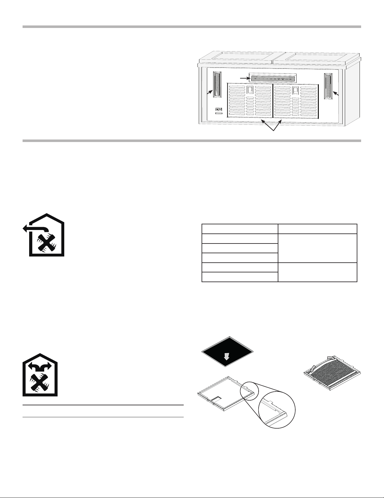
UNIT OVERVIEW
Refer to the illustration at right to identify the parts of your
appliance:
A: Filters
B: LED modules
C: Touch control panel.
A
B
B
C
B
A
Slot
Loading ...
Loading ...
Loading ...