Loading ...
Loading ...
Loading ...
10
www.bromicheating.com
INSTALLATION INSTRUCTIONS CONTINUED...
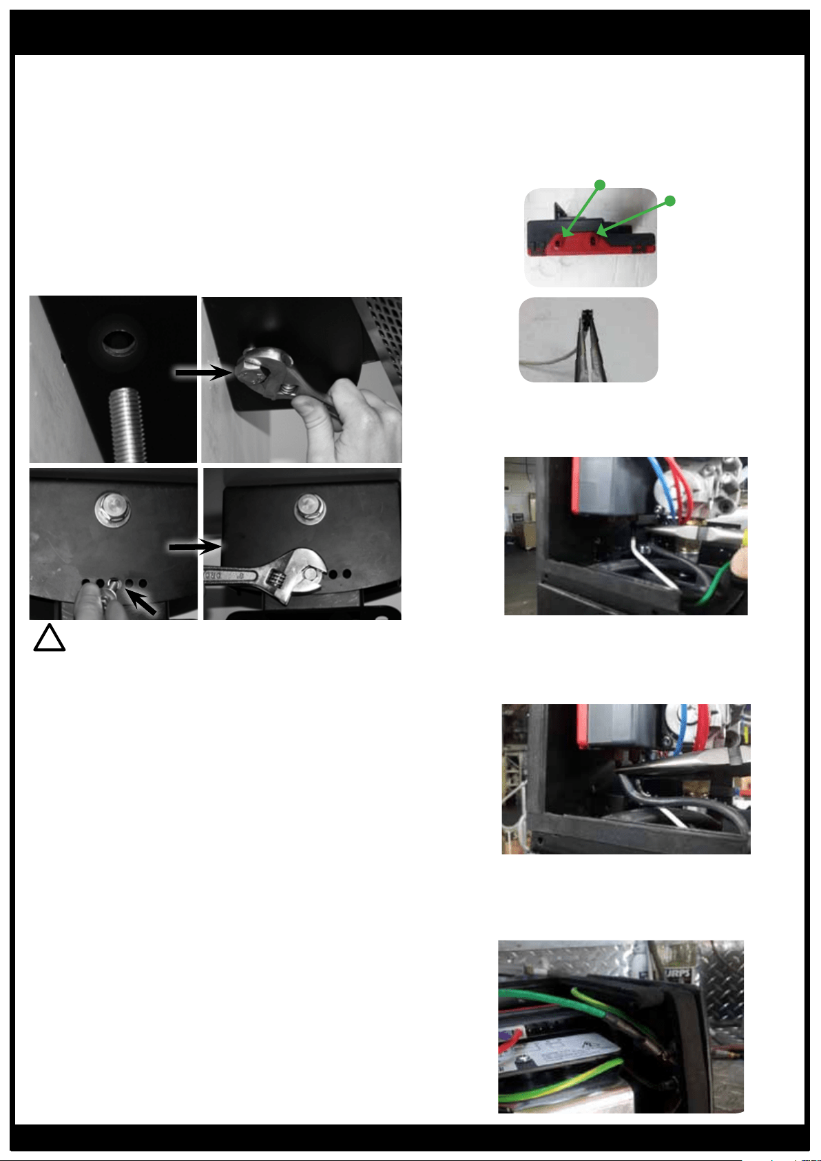
6. Insert Pivot Bolt
•Position Arm so that the rear hole’s on the mounting
arm and Control Housing are in alignment
•Insert Bolt and washer (as supplied) through Control
Housing and Mount Arm, using the hole located on
the bottom surface of the Control Housing, towards
the rear. Spanner tighten in place
•Select desired heater angle and insert the M6 Bolt
and washer (as supplied) through the bottom surface
of Control Housing into the mounting arm, using the
corresponding hole. (Heaters angle will be 0º, 10º or
20º). Spanner tighten in place
7. Connect the 3 wires from the heater by carefully following
the instructions below
IMPORTANT
Electrical connections must be completed by trained and
authorized electrical technicians only!
!
For Honeywell Control
•Using a pair of needle nose pliers, grip the white
ionisation terminal as shown, being mindful of the
terminal pins of the control module.
Ignition (smaller terminal)
Ionisation
(larger terminal)
•Insert the ionisation terminal into the terminal pin
furthest away.
•Ensure that the terminal firmly clicks into place.
•Insert Repeat the process with the black ignition
cable inserting the terminal into the closer, smaller
terminal pin.
•Insert Plug the green earth terminal into one of the
available spade terminals attached to the top of the
wall bracket.
PLEASE NOTE: THERE IS NO NEED TO
REMOVE OR UNPLUG THE CONTROL
MODULE FROM THE GAS VALVE OR
WALL BRACKET ASSEMBLY
Loading ...
Loading ...
Loading ...