Section 4 - ADJUSTMENTS & REPAIR
4.2.1.
DECK
SUPPORT
BRACKET
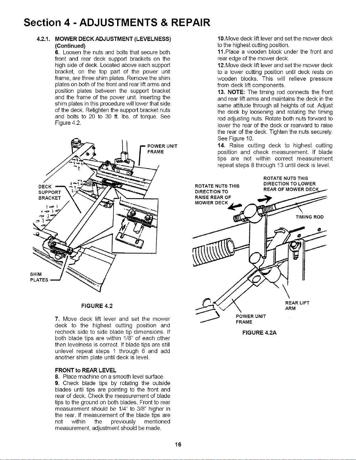
MOWER DECK ADJUSTMENT (LEVELNESS)
(Continued)
6. Loosen the nuts and bolts that secure both
front and rear deck support brackets on the
high side of deck. Located above each support
bracket, on the top part of the power unit
frame, are three shim plates. Remove the shim
plates on both of the front and rear lift arms and
position plates between the support bracket
and the frame of the power unit. Inserting the
shim plates in this procedure will lower that side
of the deck. Retighten the support bracket nuts
and bolts to 20 to 30 ft. Ibs. of torque. See
Figure 4.2.
POWER UNIT
FRAME
SHIM
PLATES
FIGURE 4.2
7. Move deck lift lever and set the mower
deck to the highest cutting position and
recheck side to side blade tip dimensions. If
both blade tips are within 1/8" of each other
then levelness is correct. If blade tips are still
unlevel repeat steps 1 through 6 and add
another shim plate until deck is level.
FRONT to REAR LEVEL
8. Place machine on a smooth level surface.
9. Check blade tips by rotating the outside
blades until tips are pointing to the front and
rear of deck. Check the measurement of blade
tips to the ground on both blades. Front to rear
measurement should be 1/4" to 3/8" higher in
the rear. If measurement of the blade tips are
not within the previously mentioned
measurement, adjustment should be made.
10.Move deck lift lever and set the mower deck
to the highest cutting position.
11,Place a wooden block under the front and
rear edge of the mower deck.
12.Move deck lift lever and set the mower deck
to a lower cutting position until deck rests on
wooden blocks. This will relieve pressure
from deck lift components.
13. NOTE: The timing rod connects the front
and rear lift arms and maintains the deck in the
same attitude through all heights of cut. Adjust
the deck by loosening and rotating the timing
rod adjusting nuts. Rotate both nuts forward to
lower the rear of the deck or rearward to raise
the rear of the deck. Tighten the nuts securely.
See Figure 10.
14. Raise cutting deck to highest cutting
position and check measurement. If blade
tips are not within correct measurement
repeat steps 8 through 13 until deck is level.
ROTATE NUTS THIS
DIRECTION TO
RAISE REAR OF
MOWERDECK
ROTATE NUTS THIS
DIRECTION TO LOWER
REAR OF MOWER DECK
TIMING ROD
POWER UNIT
FRAME
REAR LIFT
ARM
FIGURE 4.2A
16
2 YEAR LIMITED WARRANTY
For two (2) years from purchase date for the original purchaser's use, SNAPPER, through any authorized
SNAPPER dealer will replace, free of charge (except for taxes where applicable), any part or parts found upon
examination by the factory at McDonough, Georgia, to be defective in material or workmanship or both.
®
SNAPPER FIELD SERVICEABLE SPINDLES and their components used on SNAPPER PRO Mid Size walks
and SNAPPERZRIDER '_ ride on commercial equipment have a three (3) year limited warranty against defects
in material or workmanship or both.
All transportation costs incurred by the purchaser in submitting material to an authorized SNAPPER dealer for
replacement under this warranty must be paid by the purchaser.
This warranty does not apply to engines and their components, and batteries, as these items are warranted
separately. This warranty does not apply to parts that have been damaged by accident, alteration, abuse,
improper lubrication, normal wear, or other cause beyond the control of SNAPPER. This warranty does not
cover any machine or component that has been altered or modified, changing safety, performance, or durability.
Batteries have a one (1) year prorated warranty period with free replacement if required during the first ninety
(90) days from the original purchase date. SNAPPER will not be responsible for any installation cost incurred.
The battery warranty only covers original equipment batteries and does not cover damage to the battery or
machine caused by neglect or abuse, destruction by fire, explosion, freezing, overcharging, improper
maintenance, or use of improper electrolyte.
There is no other express warranty.
DISCLAIMER OF WARRANTY
Implied warranties, including those of merchantability and fitness for a particular purpose, are limited to
two (2) years from purchase date for the original purchaser's use, and up to the extent permitted by law
and all implied warranties are excluded. This is the exclusive remedy. Liabilities for consequential
damages, under any and all warranties are excluded.
Some states do not allow limitations on how long an implied warranty lasts, or do not allow the
exclusion or limitation of incidental or consequential damages, so the above limitation or exclusion ma_
not apply to you.
This warranty gives you specific legal rights, and you may also have other rights which vary from state to state.
WARNING: THE USE OF REPLACEMENT PARTS OTHER THAN GENUINE SNAPPER PARTS MAY
IMPAIR THE SAFETY OF SNAPPER PRODUCTS AND WILL VOID ANY LIABILITY AND WARRANTY BY
SNAPPER ASSOCIATED WITH THE USE OF SUCH PARTS.
IMPORTANT: Please fill out the attached SNAPPER Product Registration Card immediately and maii to:
Snapper's Product Registration Center, P.O. Box 1379, McDonough, Georgia. 30253
24
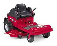
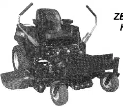
Safety Instructions & Operator's Manual for
MID MOUNT Z-RIDER
ZERO TURNING
HYDRO DRIVE
SERIES 0
IMPORTANT
Snapper products are built using engines that meet or exceed all applicable emissions requirements on the
date manufactured. The labels on those engines contain very important emissions information and critical
safety warnings. Read, Understand, and Follow all warnings and instructions in this manual, the engine
manual, and on the machine, engine and attachments. If you have any questions about your Snapper product,
contact your local authorized Snapper dealer or contact Snapper Customer Service at Snapper, McDonough,
GA. 30263. Phone: (1-800-936-2967).
J_ WARNING: The engine exhaust from this product contains chemicals known to the State I
of California to cause cancer, birth defects or other reproductive harm.
I
SNAPPERMcDonough,GA. 30253 U.S.A.
COPYRIGHT © / 999
SNAPPER INC
ALL RIGHTS RESERVED
32
MANUAL No. 4-6481 (REV. 2, 8/20/99)