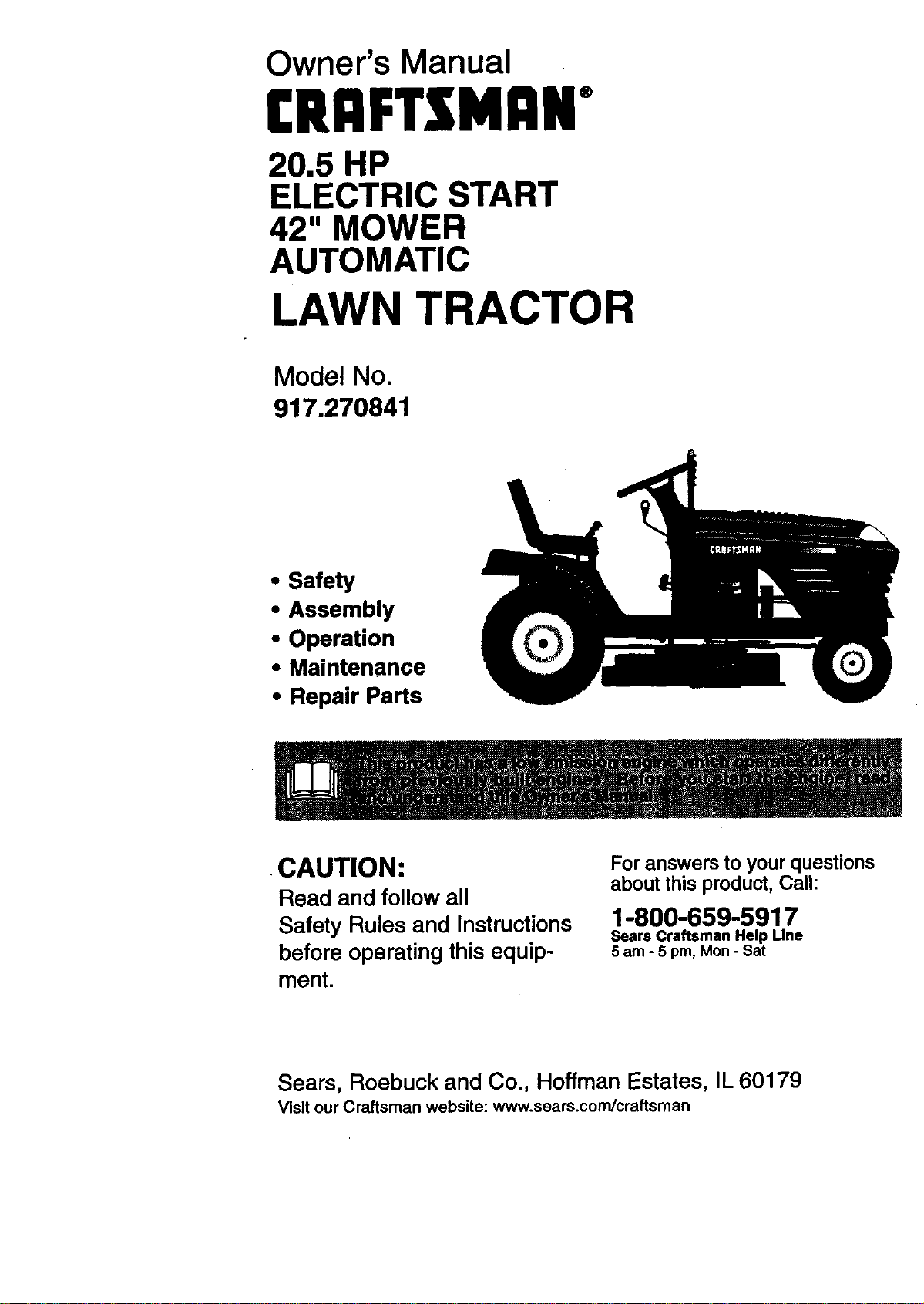
Owner's Manual
(RI:IFTXNI:IN"
20.5 HP
ELECTRIC START
42" MOWER
AUTOMATIC
LAWN TRACTOR
Model No.
917.270841
• Safety
• Assembly
• Operation
• Maintenance
• Repair Parts
•CAUTION:
Read and follow all
Safety Rules and Instructions
before operating this equip-
ment.
For answers to yourquestions
aboutthis product,Call:
1-800-659-5917
Sears Craftsman Help Line
5 am - 5 pm, Mon - Sat
Sears, Roebuck and Co., Hoffman Estates, IL 60179
Visit our Craftsman website: www.sears.com/craftsman
Warranty...:.........: ................ ;.................. 2
Safety Rules ............1............. _................ 2
Product Specifications .......................... 5
Assembly ............................... :................ 8
Operation .................. ,.;......................... 12
Maintenance Schedule ......................... 19
Maintenance ......................................... 19
Service and Adjustments...................... 23
Storage ................................................. 29
Troubleshooting.................................... 31
Repair Parts ......................................... 34
Parts Ordering ....................... Back Cover
LIMITED TWO YEAR WARRANTY ON CRAFTSMAN RIDING EQUIPMENT
For two (2) years from the date of purchase, ifthis Craftsman Riding Equipment is main-
tained, lubricated and tuned up according to the instructions in the owner's manual,
Sears will repair or replace, free of charge, any parts found to be defective in matedal or
workmanship.
This Warranty does not cover.
• Expendable items which become wom during normal use, such as blades, spark
plugs, air cleaners, belts, etc.
• Tire replacement or repair caused by punctures from outside objects, such as nails,
thorns, stumps, or glass.
• Repairs necessary because of operator abuse, negligence, improper storage or acci-
dent or the failure to maintain the equipment according to the instructionscontained in
the owner's manual.
• Riding equipment used for commercial or rental purposes.
LIMITED 90 DAY WARRANTY ON BATTERY
For ninety (90) days from date of purchase, if any battery included with this riding equip-
ment proves defective in material or workmanship and our testing determines the bat-
tery will not hold a charge, Sears will replace the battery at no charge. In-home warranty
service on your Craftsman ridingequipment is available at no charge for 30 days from
the date of purchase. Please contact your nearest service center. After 30 days from the
date of purchase, warranty service is available by taking your Craftsman dding equip-
ment to your nearest Sears Service Center. (In-home warranty service will stillbe avail-
able after 30 days from the date of purchase but a standard trip charge will apply). This
warranty applies only while this product isinthe United States. This Warranty gives you
specific legal rights, and you may also have other dghts which may vary from state to
state.
Sears, Roebuck and Co., D/817 WA, Hoftman Estates, IL 60179
GENERAL OPERATION
• Read, understand, and fellow all instruc-
tions in the manual and on the machine
before starting.
• Only allow responsible adults, who are
familiar with the instructions, to operate
the machine.
• Clear the area of objects such as rocks,
toys, wire, etc., which could be picked
up and thrown by the blade.
• Be sure the area isclear of other people
before mowing. Stop machine ifanyone
enters the area.
2
• Never carry passengers.
• Do not mow in reverse unless absolute-
ly necessary. Always look down and
behind before and while backing.
• Be aware of the mower discharge direc-
tion and do not point it at anyone. Do
not operate the mower without either
the entire grass catcher or the guard in
place.
• Slow down before turning.
• Never leave a running machine unat-
tended. Always turn off blades, set park-
ing brake, stop engine, and remove
keys before dismounting.
• Turn off blades when not mowing.
• Stop engine before removing grass
catcher or unclogging chute.
• Mow only in daylight or good artificial
light.
• Do not operate the machine while under
the influence of alcohol or drugs,
• Watch for traffic when operating near or
crossing roadways.
• Use extra care when loading or unload-
ing the machine into a trailer or truck.
SLOPE OPERATION
Slopes are a major factor related to loss-
of-control and tipover accidents, which
can resultin severe injury or death. All
slopes require extra caution. Ifyou cannot
back up the slope or if you feel uneasy on
it, do not mow it.
DO:
• Mow up and down slopes, not across,
• Remove obstacles such as rocks,tree
limbs, etc.
• Watch for holes, ruts, orbumps. Uneven
terrain could overturn the machine. Tall
grass can hide obstacles.
• Use slow speed. Choose a low gear so
that you will not have to stopor shift
while on the slope.
• Follow the manufacturer's recommen-
dations Forwheel weights or counter-
weights to improve stability.
• Use extra care with grass catchers or
other attachments. These can change
the stabilityof the machine.
• Keep all movement on the slopes slow
and gradual Do not make sudden
changes in speed or direction.
• Avoid starting or stoppingon a slope. If
tires lose traction, disengage the blades
and proceed slowly straight down the
slope.
DO NOT:
• Denottum on slopes unless necessary,
and then, turn slowly and gradually
downhill, ifpossible.
• Do not mow near drop-offs, ditches, or
embankments. The mower could sud-
denly turn over if a wheel is over the
edge of a cliff or ditch, or if an edge
caves in.
• Do not mow on wet grass. Reduced
tractioff could cause sliding.
• Do not try to stabilize the machine by
puttingyour foot on the ground.
• Do not use grass catcher on steep
slopes.
CHILDREN
Tragic accidents can occur if the operator
is not alert to the presence of children.
Children are often attracted to the
machine and the mowing activity.Never
assume that children will remain where
you lastsaw them.
• Keep childrenout of the mowing area
and under the watchfulcare of another
responsible adult.
• Be alert and rum machine off if children
enter the area.
• Before and when backing, look behind
and down for small children.
• Never carry children. They may fall off
and be seriously injuredor interfere with
safe mach!ne operation.
• Never allow children to operate the
machine.
• Use extra care when approaching blind
comers, shrubs, trees, or other objects
that may obscure vision.
SERVICE
• Use extra care in handling gasoline and
other fuels. They are flammable and
vapors are explosive.
Use only an approved container.
Never remove gas cap or add fuel
with the engine running. Allow en-
gine to coolbefore refueling. Do not
smoke.
Never refuelthe machine indoors.
Never store the machine orfuel
container inside where there is an
open flame, such as a water heater.
• Never run a machine inside a closed
area.
• Keep nuts and bolts, especiallyblade
attachment bolts,tight and keep equ=p-
ment in good condition.
• Never tamper with safety devices.
Check their proper operation regularly.
• Keep machine free ofgrass, leaves, or
other debris build-up.Clean oil orfuel
spillage. Allow machine tocool before
storing.
• Stop and inspectthe equipment ifyou
strike an object. Repair, if necessary,
before restarting.
• Nevermakeadjustmentsorrepairswith
theenginerunning.
• Grass catcher components are subject
to wear, damage, and deterioration,
which could expose moving parts or
allow objects to be thrown. Frequently
check components and replace with
manufacturer's recommended pads,
when necessary.
• Mower blades are sharp and can cut.
Wrap the blade(s) or wear gloves, and
use extra caution when servicingthem.
• Check brake operation frequently.
Adjustand service as required.
• Be sure the area is clear of other people
before mowing. Stop machine if anyone
enters the area.
• Never carry passengers.
• Do not mow in reverse unless absolute-
ly necessary. Always look down and
behind before and while backing.
• Never carry chjIdren. They may fall off
and be seriously injured or interfere with
safe machine operation.
• Keep children out of the mowing area
and under the watchful care of another
responsible adult.
• Be alert and tum machine off if children
enter the area.
• Before and when backing, look behind
and down for small children.
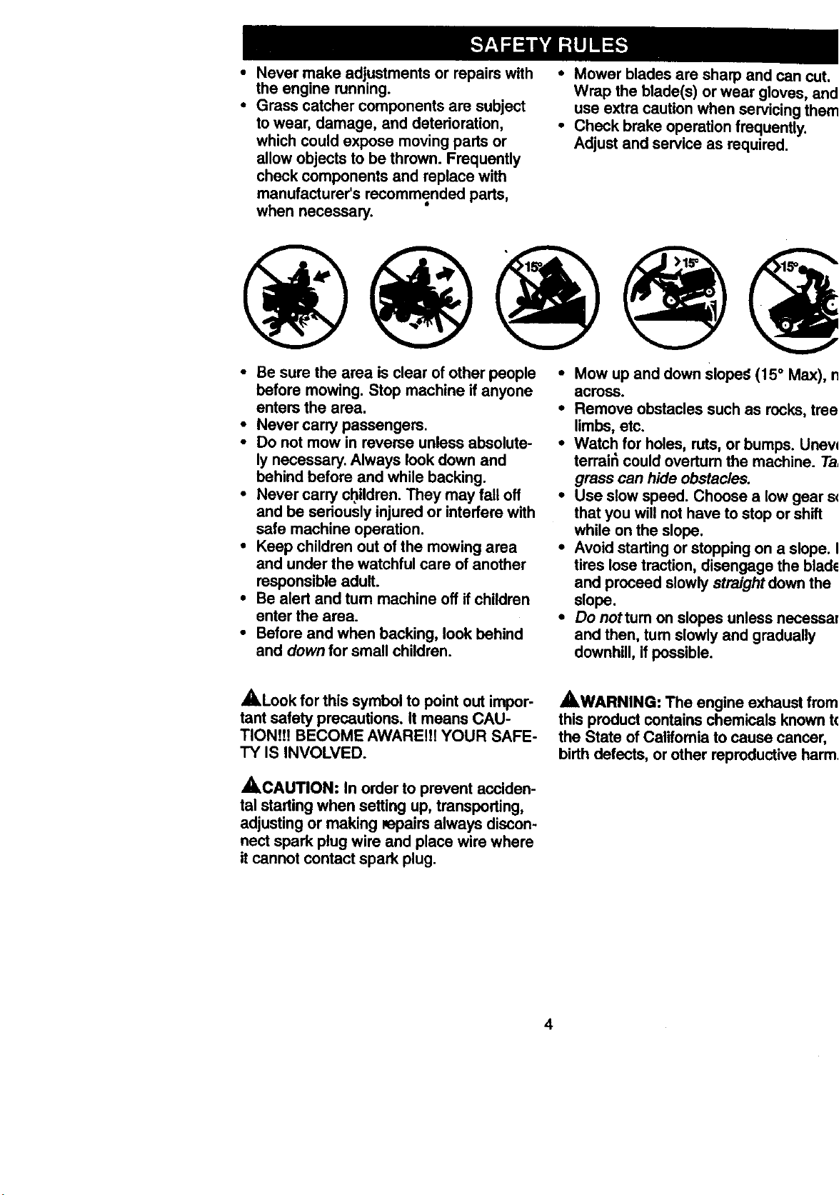
• Mow up and down Sloped (15 ° Max), nc
across.
• Remove obstacles such as recks, tree
limbs, etc.
• Watch for holes, ruts, or bumps. Uneve
terrair_ could overtum the machine. Tal,
grass can hide obstacles.
• Use slow speed. Choose a low gear so
that you will not have to stop or shift
while on the slops.
• Avoid starting or stopping on a slope. If
tires lose traction, disengage the blade=
and proceed slowly straight down the
slops.
• Do nottum on slopes unless necessar
and then, tum slowly and gradually
downhill, if possible.
,_Look for this symbol to point out impor-
tant safety precautions. It means CAU-
TIONt!! BECOME AWAREI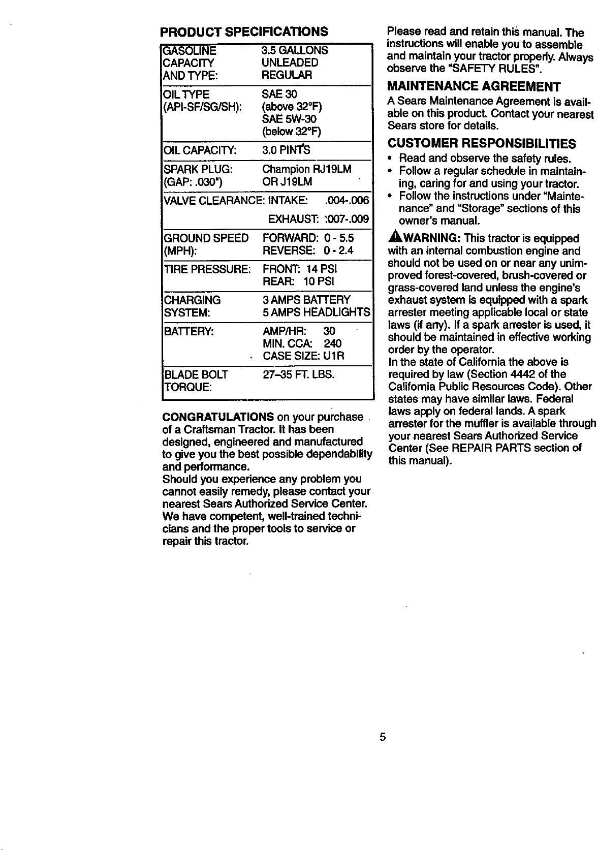
PRODUCT SPECIFICATIONS
SASOLINE 3.5 GALLONS
CAPACITY UNLEADED
AND TYPE: REGULAR
OILTYPE SAE 30
API-SF/SG/SH): (above32°F)
SAE 5W-30
(below32°F)
OiL CAPACITY: 3.0 PIN'I'S
SPARK PLUG: ChampionRJ19LM
GAP: .030") OR J19LM
VALVECLEARANCE: INTAKE: .004-.006
EXHAUST: .'007-.009
GROUND SPEED FORWARD: 0 - 5.5
(MPH): REVERSE: 0 - 2.4
TIRE PRESSURE: FRON'E 14 PSI
REAR: 10 PSI
CHARGING 3 AMPS BATTERY
SYSTEM: 5 AMPS HEADLIGHTS
BATI'ERY: AMP/HR: 30
MIN. CCA: 240
CASE SIZE: U1R
BLADEBOLT 27-35 FT. LBS.
TORQUE:
CONGRATULATIONS on your purchase
of a Craftsman Tractor. It has been
designed, engineered and manufactured
to give you the best possible dependability
and performance.
Should you experience any problem you
cannot easily remedy, please contact your
nearest Sears Authorized Service Center.
We have competent, well-trained techni-
cians and the proper toolsto service or
repair this tractor.
Please road and retain this manual. The
instructionswillenable you to assemble
and maintain your tractor properly.Always
observe the "SAFETY RULES".
MAINTENANCE AGREEMENT
A Sears Maintenance Agreement isavail-
able on this product. Contact your nearest
Sears store for details.
CUSTOMER RESPONSIBILITIES
• Read and observe the safety rules.
• Follow a regular schedule in maintain-
ing, caring for and using your tractor.
• Follow the instructionsunder =Mainte-
nance" and =Storage"sections of this
owner's manual.
_,WARNING: This tractor is equipped
with an internal combustion engine and
should not be used on or near any unim-
proved forest-covered, brush-covered or
grass-covered land unless the engine's
exhaust system is equipped with a spark
arraster meeting applicable local or state
laws (if any). If a spark arrester is used, it
should be maintained in effective working
order by the operator.
In the state of California the above is
required by law (Section 4442 ofthe
Califomia Public Resources Code). Other
states may have similar laws. Federal
laws apply on federal lands. A spark
arraster forthe muffler is available through
your nearest Sears Authorized Service
Center (See REPAIR PARTS section of
this manual).
5
0
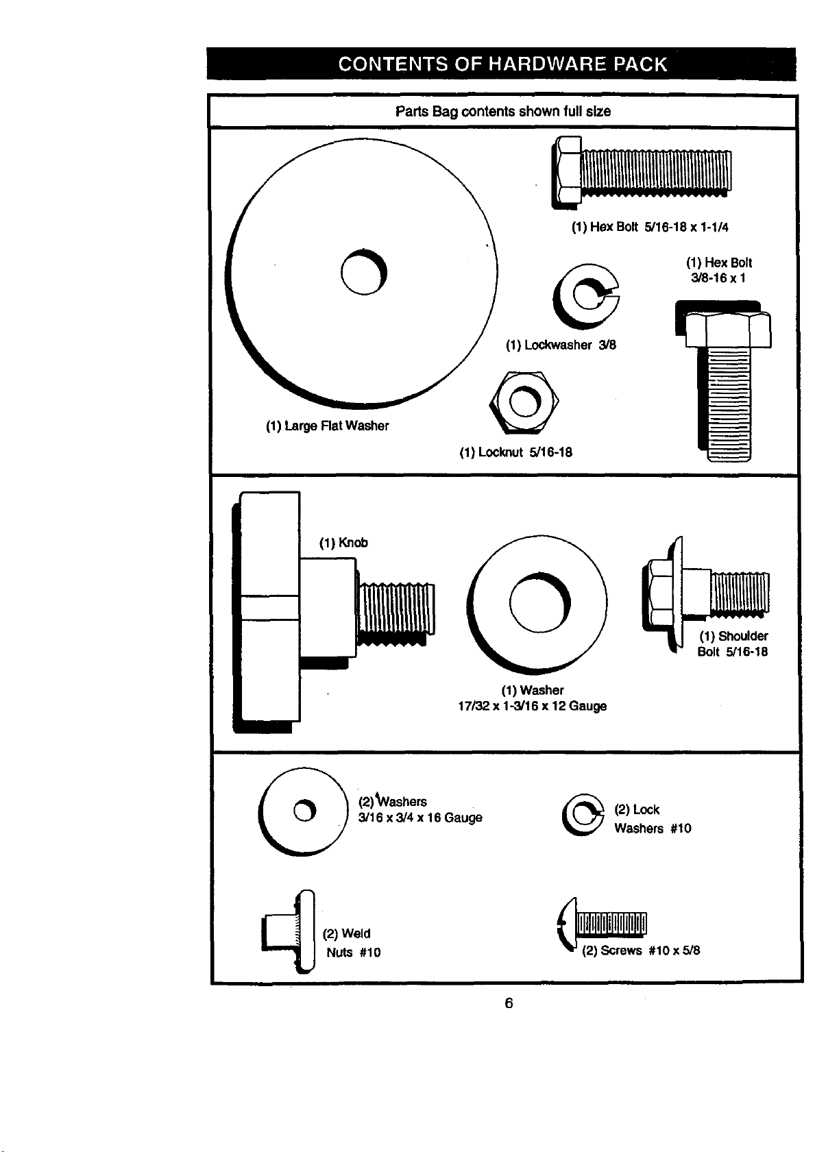
(1) Large FlatWasher
Parts Bag contents shown full size
I
(1) Hex Bolt 5/16-18x 1-1/4
(1) HexBolt
3/8-16 x I
(1) Lockwasher 3/8
@
(1) Locknut5/16-18
(1) Knob
(1) Washer
17/32 x 1-3/16 x 12 Gauge
(1) Shoulder
Bolt 5/16-18
(2)_Washers
3/16 x 3/4 x 16 Gauge
_ (2) Lock
Washers #10
(2) Weld
Nuts #10
6
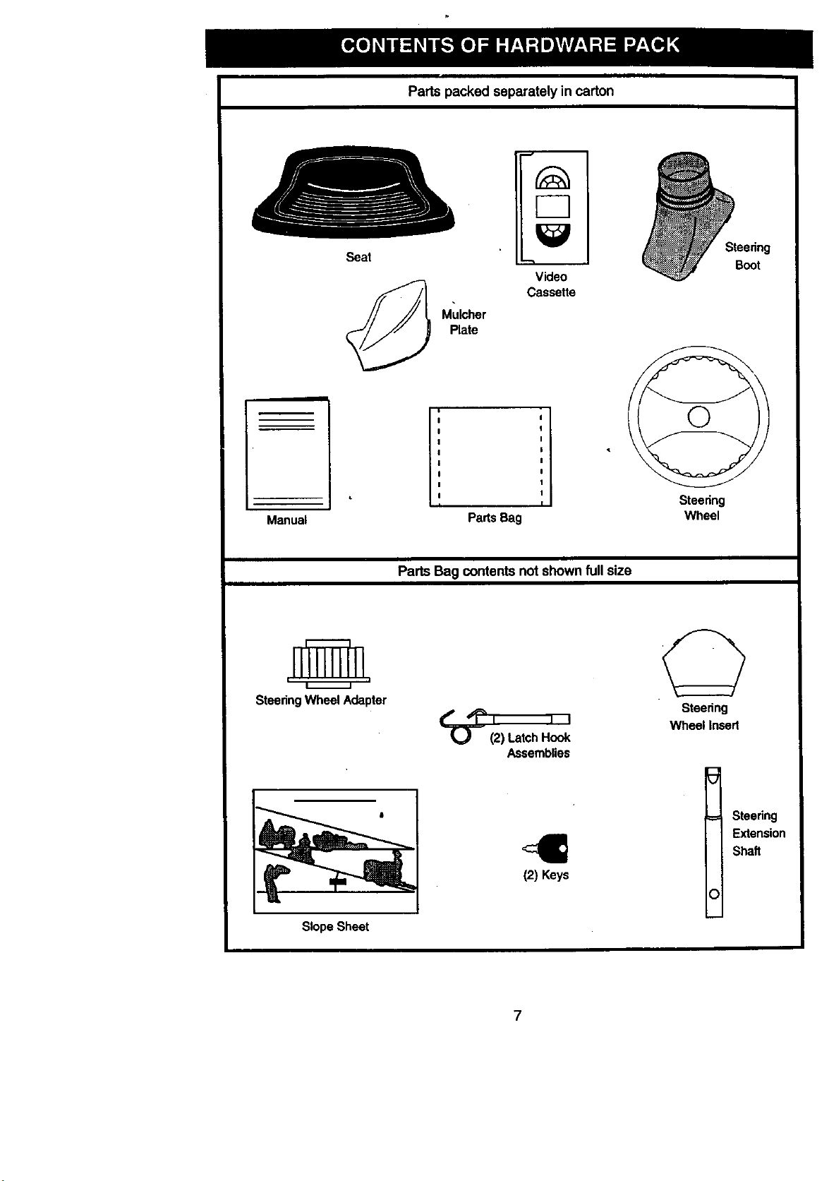
Parts packed separately in carton
Seat
Mulcher
Plate
Video
Cassette
Steering
Boot
Manual
I i
,I
Parts Bag
Steering
Wheel
Parts Bag contents not shown fullsize
i i
Steedng Wheel Adapter
Slope Sheet
(2) Latch Hook
Assemblies
(2) Keys
Steering
Wheel Insed
O
Steering
Extension
Shaft
7
Yournewtractorhasbeenassembledatthefactorywithexceptionofthosepartsleft
unassembledforshippingpurposes.Toensuresafeandproperoperationofyourtract
allpartsandhardwareyouassemblemustbetightenedsecurely.Usethecorrecttool.,
asnecessaryto insurepropertightness.Reviewthevideocassettebeforeyoubegin.
TOOLS REQUIRED FOR
ASSEMBLY
A socket wrench set willma_e assembly
easier. Standard wrench sizes you need
are listed below.
(1) 9/16" wrench
(1) 3/4" wrench
(2) 1/2" wrench
(1) Utility knife
(1)Pliers
(1) 3/4" Socket w/
drive rachet
(1) Phillips Screw-
ddver
(1) Tire pressure
gauge
When right or left hand is mentioned in
this manual, it means, from your point of
view, when you are in the operating posi-
tion (seated behind the steering wheel).
TO REMOVE TRACTOR FROM
CARTON
UNPACK CARTON
• Remove all accessible loose parts and
parts boxes froth shipping carton (See
page 6).
• Cut, from top to bottom, along lines on
all four comers of shipping carton, and
lay panels flat.
• Check for any additional loose parts or
boxes and remove.
BEFORE ROLLING TRACTOR OFF
SKID
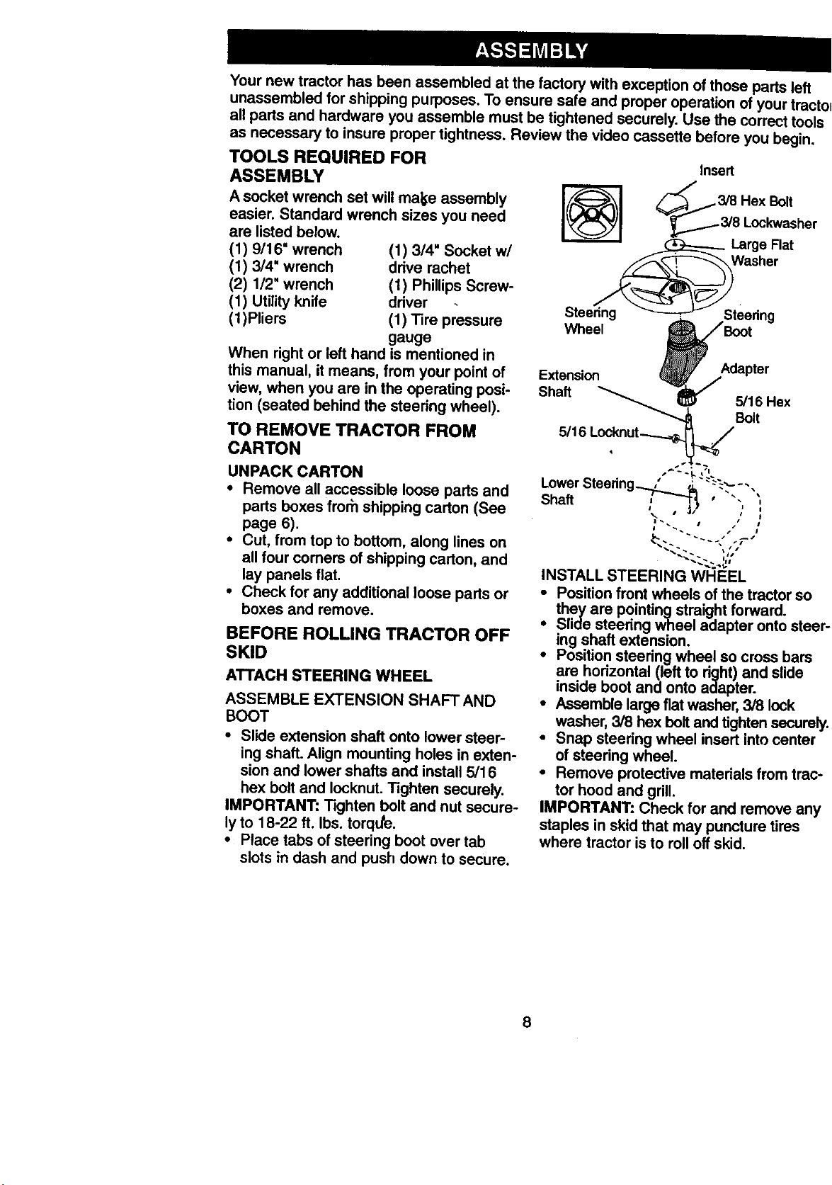
ATTACH STEERING WHEEL
ASSEMBLE EXTENSION SHAFT AND
BOOT
• Slide extension shaft onto lower steer-
ing shaft. Align mounting holes in exten-
sion and lower shafts and install 5/16
hex bolt and Iocknut. Tighten securely.
IMPORTANT: Tighten bolt and nut secure-
lyto 18-22 ft. Ibs. torque.
• Place tabs of steering boot over tab
slots in dash and push down to secure.
Insert
_3_ 18a_gO_eF,kWa';her
Wt_eel
Extension
Shaft _ 5/_16Hex
5116 Locknut__'.
Lower Steering_ f_ "-"_ °-.
Sha. ," ,3} ' "
i
I t
INSTALL STEERING WHEEL
• Position front wheels of the tractor so
they are pointingstraight forward.
i Slide steering wheel adapter onto steel
ing shaft extension.
Position steering wheel so cross bars
are horizontal (left to right) and slide
inside boot and onto adapter.
• Assemble large fiat washer, 3/8 lock
washer, 3/8 hex bolt and tighten secure!
• Snap steering wheel insert into center
of steedng wheel.
• Remove protective materials from trac,
tor hood and grill.
IMPORTANT: Check for and remove any
staples in skid that may puncture tires
where tractor is to roll off skid.
8
HOW TO SET UP YOUR TRACTOR
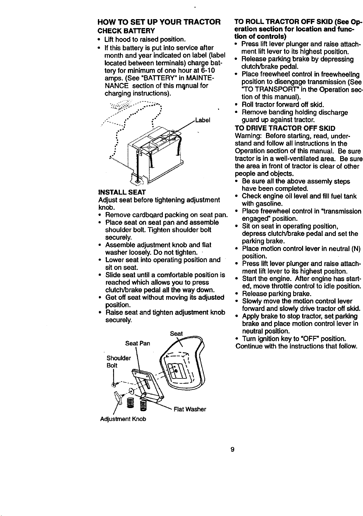
CHECK BATTERY
• Lift hood to raised position.
• If this battery is put into service after
month and year indicated on label (label
located between terminals) charge bat-
tery for minimum of one hour at 6-10
amps. (See "BATTERY" in MAINTE-
NANCE section of this m_tnual for
charging instructions).
,: ." _Label
",....%
INSTALL SEAT
Adjust seat before tightening adjustment
knob.
• Remove cardboard packing on seat pan.
• Place seat on seat pan and assemble
shoulder bolt. Tighten shoulder bolt
securely.
• Assemble adjustment knob and flat
washer loosely. Do not tighten.
• Lower seat into operating position and
sit on seat.
• Slide seat until a comfortable position is
reached which allows you to press
clutch/brake pedal all the way down.
• Get off seat without moving its adjusted
position.
• Raise seat and tighten adjustment knob
securely.
Seat
Seat Pan
Shoulder
Bolt
TO ROLL TRACTOR OFF SKID (See Op-
eration section for location and func-
tion of controls)
• Press lift lever plunger and raise attach-
ment lift lever to its highest position.
• Release parking brake by depressing
clutch/brake pedal.
• Place freewheel control in freewheeling
position to disengage transmission (See
"TO TRANSPORT" in the Operation sec-
tion of this manual).
• Roll tractor forward off skid.
• Remove banding holding discharge
guard up against tractor.
TO DRIVE TRACTOR OFF SKID
Waming: Before starting, read, under-
stand and follow all instructions in the
Operation section of this manual. Be sure
tractor is in a well-ventilated area. Be sure
the area in front of tractor is clear of other
people and objects.
• Be sure all the above assemly steps
have been completed.
• Check engine oil level and fill fuel tank
with gasoline.
• Place freewheel control in "transmission
engaged" position.
• Sit on seat in operating position,
depress clutch/brake pedal and set the
parking brake.
• Place motion control lever in neutral (N)
position.
• Press lift lever plunger and raise attach-
ment lift lever to its highest positon.
• Start the engine. After engine has start-
ed, move throttle control to idle position.
• Release parking brake.
• Slowly move the motion control lever
forward and slowly drive tractor off skid.
• Apply brake to stop tractor, set parking
brake and place motion control lever in
neutral position.
• Turn ignition key to "OFF" position.
Continue with the instructions that follow.
Adjustment Knob
Flat Washer
9
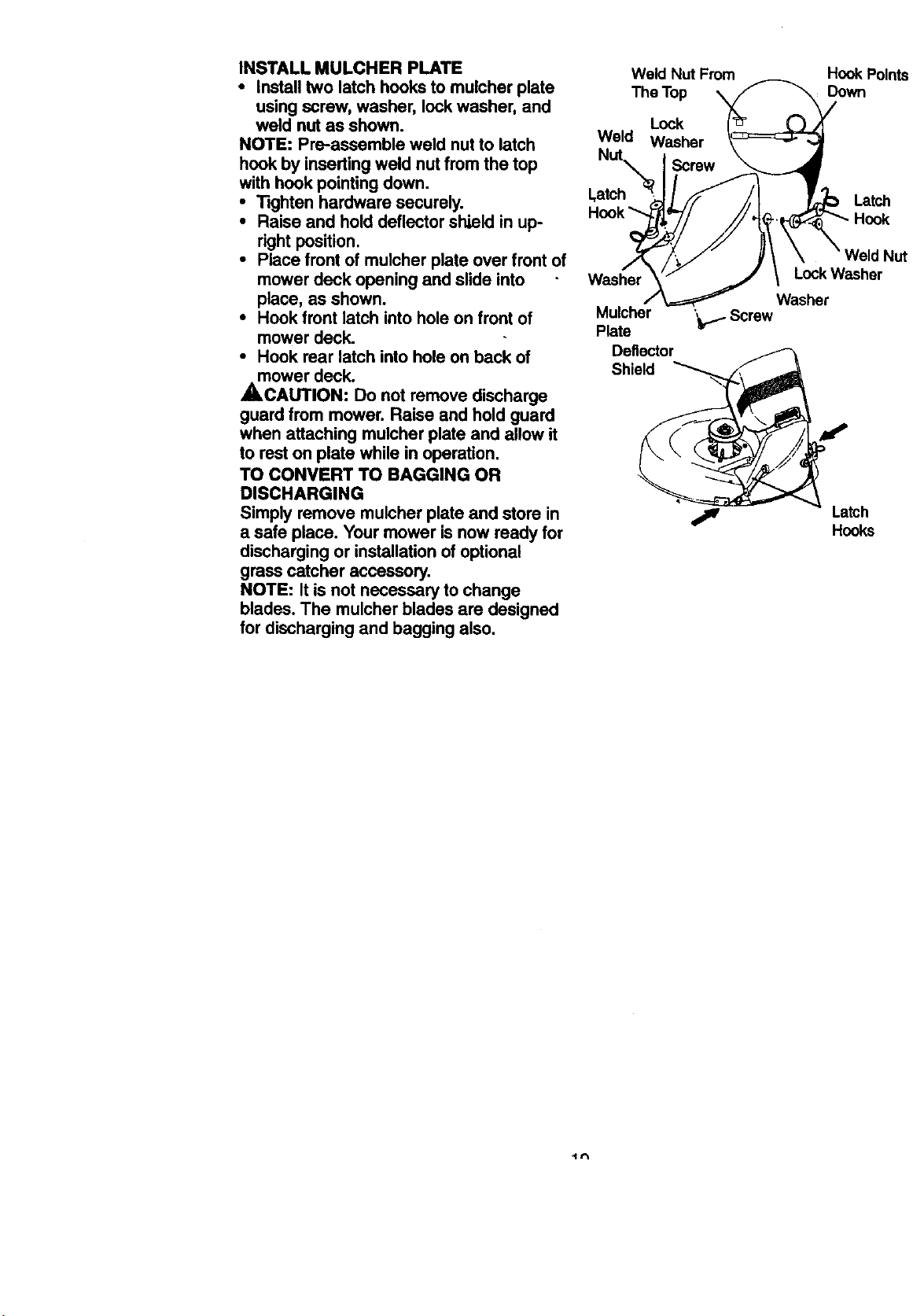
INSTALLMULCHERPLATE
• install two latch hooks to muicher plate
using screw, washer, lock washer, and
weld nut as shown.
NOTE: Pre-assemble weld nut to latch
hook by inserting weld nut from the top
with hook pointing down.
• Tighten hardware securely.
• Raise and hold deflector shield in up-
right position.
• Place front of mulcher plate over front of
mower deck opening and slide into
place, as shown.
• Hook front latch into hole on front of
mower deck.
• Hook rear latch into hole on back of
_mower deck.
CAUTION: Do not remove discharge
guard from mower. Raise and hold guard
when attaching mulcher plate and allow it
to rest on plate while in operation.
TO CONVERT TO BAGGING OR
DISCHARGING
Simply remove mulcher plate and store in
a safe place. Your mower is now ready for
discharging or installation of optional
grass catcher accessory.
NOTE: It is not necessary to change
blades. The mulcher blades are designed
for discharging and bagging also.
Weld Nut From
The Top
Lock
Weld Washer
Hook Points
Down
Latch
Latch
Washer
Mulcher
Plate
Deflector
Shield
Nut
Lock Washer
Washer
'_b1. Screw
Latch
Hooks
4f't
CHECK TIRE PRESSURE
The tires on your tractor were ovefinflated
at the factory for shipping purposes.
Correct tire pressure is important for best
cutting performance.
• Reduce tire pressure to PSI shown in
"PRODUCT SPECIFICATIONS" on
page 5 of this manual.
CHECK DECK LEVELNESS
For best cutting results, mower housing
should be properly leveled. See "TO
LEVEL MOWER HOUSING" in the
Service and Adjustments section ofthis
manual.
CHECK FOR PROPER POSITION OF
ALL BELTS
See the figures that are shown for replac-
ing motion and mower blade drive belts in
the Service and Adjustments sectoin of
this manual. Verify that the belts are rout-
ed correctly.
CHECK BRAKE SYSTEM
After you learn how to operate your trac-
tor, check to see that the brake is propedy
adjusted. See "TO ADJUST BRAKE" in
the Service and Adjustments section of
this manual.
t/ CHECKLIST
PLEASE REVIEW THE FOLLOWING
CHECKLIST:
V' All assembly instructions have been
completed.
i# No remaining loose parts in carton.
i# Battery is propedy prepared and
charged. (Minimum 1 hourat 6 amps).
V' Seat is adjusted comfortably and
tightened securely.
v' All tires are propedy inflated. (For
shipping purposes, the tireswere
overinflated at the factory).
v" Be sure mower deck is properly leveled
side-to-side/front-to-rear for best
cutting results. (Tires must be properly
inflated for leveling).
v' Check mower and drive belts. Be sure
they are routed properly around pulleys
and inside all belt keepers.
v' Check wiring. See that all connections
are stillsecure and wires are propedy
clamped..
i,' Before drivingtractor, be surefree-
wheel control is in drive position.
WHILE LEARNING HOW TO USE YOUR
TRACTOR, PAY EXTRAATTENTION TO
THE FOLLOWING IMPORTANT ITEMS:
,/ Engine oil is at proper level.
,/ Fuel tank is filled with fresh, clean,
regular unleaded gasoline.
,/ Become familiar with all controls - their
location and function. Operate them
before you start the engine.
,/ Be sure brake system is in safe operat-
ing condition.
4* It is important to purge the transmis-
sion before operating your tractor for
the first time. Follow proper starting
and transmission purging instructions
(See "TO START ENGINE" and
"PURGE TRANSMISSION" in the Op-
eration section of this manual).
11
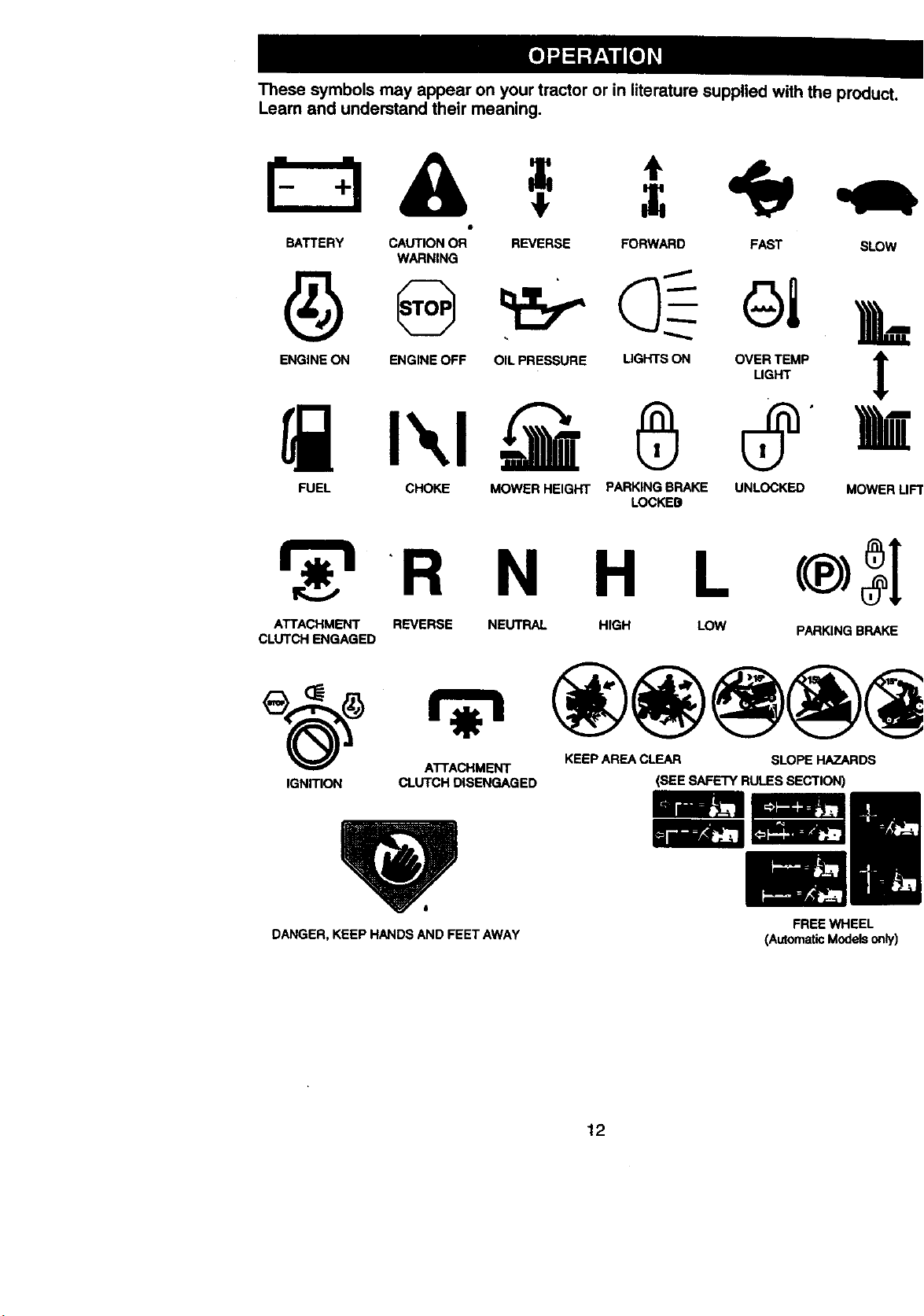
These symbols may appear on your tractor or in literature supplied with the product.
Learn and understand their meaning.
& ÷ I
BATTERY CAUTION OR* REVERSE FORWARD FAST SLOW
WARNING
ENGINE ON ENGINE OFF OIL PRESSURE LIGHTS ON OVER TEMP
LIGHT
n' u
FUEL CHOKE MOWERHEIGHT PARKINGBRAKE UNLOCKED MOWERLIFT
LOCKES
R N H L c®) l
ATTACHMENT REVERSE NEUTRAL HIGH LOW PARKING BRAKE
CLUTCH ENGAGED
ATTACHMENT KEEP AREA CLEAR SLOPE HAZARDS
IGNITION CLUTCH DISENGAGED
DANGER, KEEP HANDS AND FEET AWAY
(SEE SAFETYRULES SECTION)
FREE WHEEL
(AutomaticModelsonly)
12
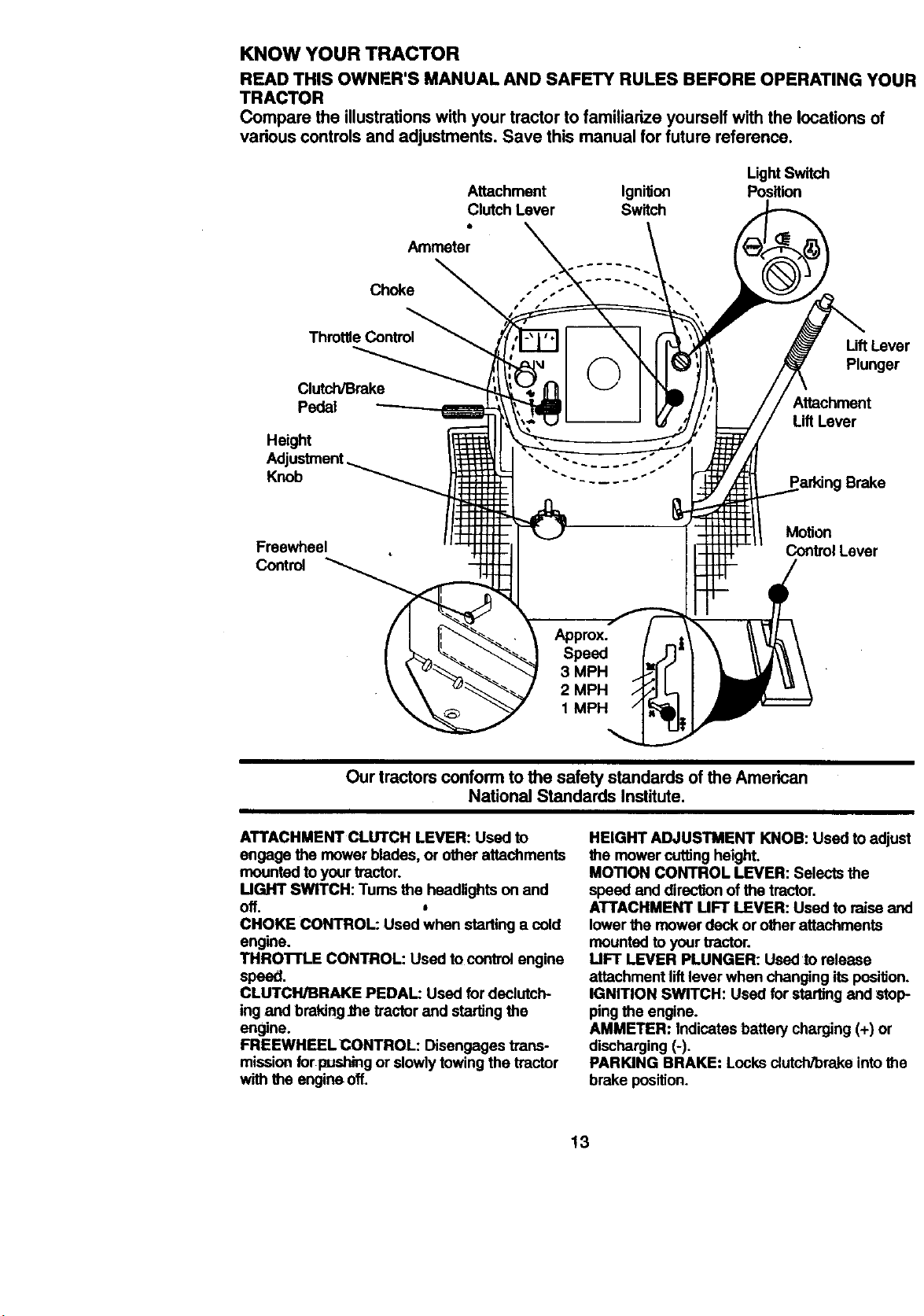
KNOW YOUR TRACTOR
READ THIS OWNER'S MANUAL AND SAFETY RULES BEFORE OPERATING YOUR
TRACTOR
Compare the illustrations with your tractor to familiarize yourself with the locations of
vadous controls and adjustments. Save this manual for future reference.
Attachment Ignition
Clutch Lever Switch
Light Switch
Position
Ammeter
Choke
Throttle Control
Clutch/Brake
Pedal
Height
Knob
Uff Lever
Plunger
Attachment
Lift Lever
Parking Brake
Freewheel
Control
Motion
Control Lever
Our tractors conform to the safety standards of the American
National Standards Institute.
ATTACHMENT CLUTCH LEVER: Used to
engage the mower blades, or other attachments
mounted to your tractor.
MGHT SWITCH: Tums the headlights on and
off.
CHOKE CONTROL: Used when starting a cold
engine.
THROI"rLE CONTROL: Used to controlengine
speed.
CLUTCH/BRAKE PEDAL: Used for dedutch-
ing and brakingJhetractor and starting the
engine.
FREEWHEEL CONTROL: Disengages trans-
mission for pushing or slowlytowing the tractor
with the engine off.
HEIGHT ADJUSTMENT KNOB: Used to adjust
the mower cuttingheight.
MOTION CONTROL LEVER: Selects the
speed end direction of the tractor.
ATTACHMENT MR" LEVER: Used to raise and
lowerthe mower deck or other attachments
mounted to yourtractor.
UFT LEVER PLUNGER: Used to release
attachment liftlever when changing its position.
IGNITION SWITCH: Used for startingand stop-
pingthe engine.
AMMETER: Indicates battery charging (+) or
discharging (-).
PARKING BRAKE: Locks clutch/brake intothe
brake position.
13
The operation of any tractor can result in foreign objects thrown intothe
eyes, which can resultin severe eye damage. Always wear safety glasses
or eye shields while operating your tractor or performing any adjustments c
repairs. We recommend a wide vision safety mask over spectacles, or stan-
dard safety glasses.
HOW TO USE YOUR TRACTOR
Your tractor isequipped withan operator
presence sensing switch. Wtten engine is
running, any attempt by the operator to
leave the seat without first setting the
parking brake will shut off the engine. '
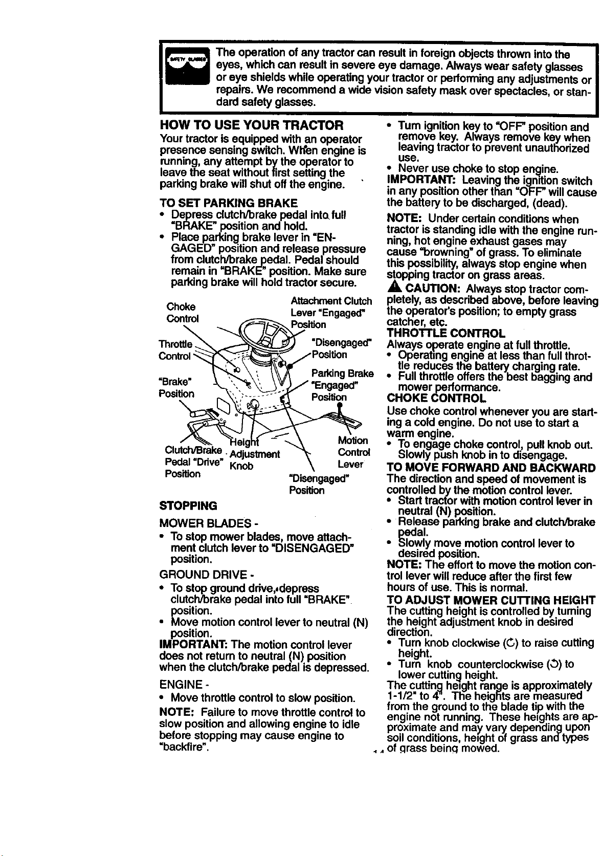
TO SET PARKING BRAKE
i Depress clutch/brake pedal intafull
"BRAKE" positionand hold.
Place parking brake lever in =EN-
GAGED" position and release pressure
from clutc=,Wbrake,_l:>edal.Pedal should
remain in BRAKE" position. Make sure
parking brake will hold tractor secure.
Choke
Control _
Thm__
=-'eaaJunve Knob
Position
Attachment Clutch
Lever =Engaged"
PosiUon
"Disengaged"
/Poslfion
Parking Brake
/ "Engaged"
Position
MolJon
_ _ntml
Lever
"Disengaged"
Position
STOPPING
MOWER BLADES -
• To step mower blades, move attach-
ment clutch lever to "DISENGAGED"
position.
GROUND DRIVE -
• To step ground ddve,,depress
clutch/brake pedal into full "BRAKE"
position.
• Move motion control lever to neutral (N)
position.
IMPORTANT: The motion control lever
does not return to neutral (N) position
when the clutch/brake pedal is depressed.
• Tum ignition key to "OFF" position and
remove key. Always remove key when
leaving tractor to prevent unauthorized
use.
• Never use choke to stop engine.
IMPORTANT: Leaving the igmtion switch
in any position other than "OFF" will cause
the battery to be discharged, (dead).
NOTE: Under certain conditions when
tractor is standing idle with the engine run-
ning, hot engine exhaust gases may
cause "browning" of grass. To eliminate
this possibility, always stop engine when
stopping tractor on grass areas.
A CAUTION: Always stop tractor com-
pletely, as described above, before leaving
the operator's position; to empty grass
catcher, etc.
THRO'n'LE CONTROL
Always operate engine at full throttle.
• Operating engine at less than full throt-
tle reduces the battery charging rate.
• Full throttle offers the best bagging and
mower performance.
CHOKE CONTROL
Use choke control whenever you are start-
ing a cold engine. Do not use to start a
warm engine.
• Toengage choke control pull knob out.
Slowly push knob n to disengage.
TO MOVE FORWARD AND BACKWARD
The direction and speed of movement is
controlled by the motion control lever.
• Start tracfor with motion control lever in
neutral (N) position.
• Release parking brake and clutch/braKe
pedal.
• Slowly move motion control lever to
desired position.
NOTE: The effort to move the motion con-
trol lever will reduce after the first few
hours of use. This is normal
TO ADJUST MOWER cu'n'ING HEIGHT
The cutting height iscontrolled by tuming
the height adjustment knob in desired
direction.
• Turn knob clockwise (C) to raise cutting
height.
• Turn knob countemlockwise (O) to
ENGINE -
• Move throttle control to slow position.
NOTE: Failure to move throttle control to
slow position and allowing engine to idle
before stopping may cause engine to
"backfire".
lower cutting height.
The cuttinq height ranqe is approximately
1-1/2" to 4". The heiglits are measured
from the ground to the blade tip with the
engine not running. These heights are ap-
proximate and may va_ depending upon
soil conditions, he=ght of grass andtypes
., of qrass beincl mowed.
• The average lawn should be cut to
approximately 2-1/2 inches during the
cool season and to over 3 inches during
hot months. For healthier and better
looking lawns, mow often and after
moderate growth.
• For best cutting performance, grass
over 6 inches in height shouldbe
mowed twice. Make the first cut rela-
tively high; the second to desired height.
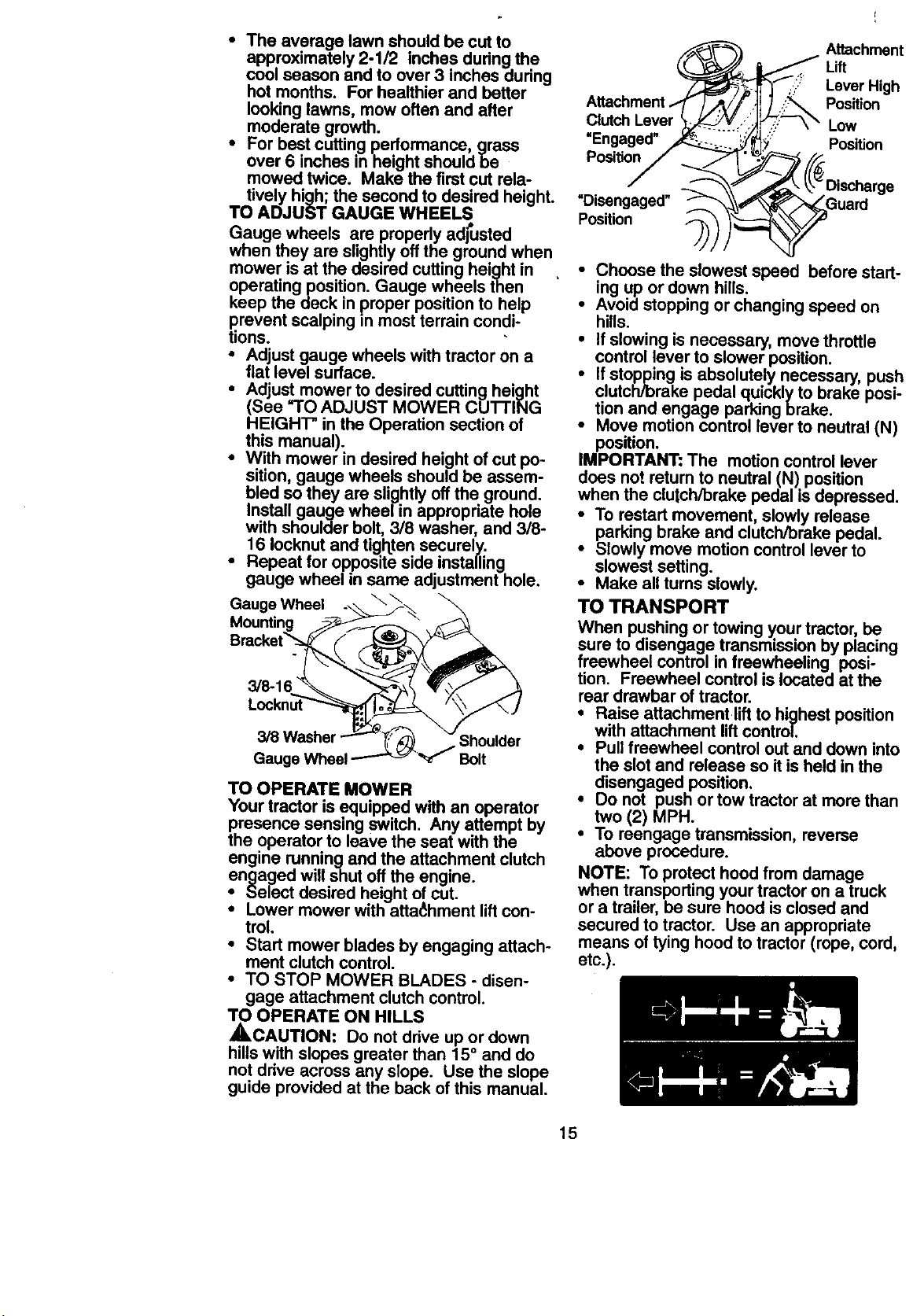
TO ADJUST GAUGE WHEELS
Gauge wheels are propedy adj_Jsted
when they are slightly off the ground when
mower is at the desired cutting height in .
operating position. Gauge wheels then
keep the deck in proper position to help
prevent scalping in most terrain condi-
tions.
• Adjust gauge wheels with tractor on a
fiat level surface.
• Adjust mower to desired cutting height
(See "TO ADJUST MOWER CUTTING
HEIGHT" in the Operation section of
this manual).
• With mower in desired height of cut po-
sition, gauge wheels should be assem-
bled so they are slightly off the ground.
Install gauge wheel in appropriate hole
with shoulder bolt, 3/8 washer, and 3/8-
16 Iocknut and tighten securely.
• Repeat for opposite side installing
gauge wheel in same adjustment hole.
Gauge Wheel
Bracke
Gauge Wheel
Shoulder
Bolt
TO OPERATE MOWER
Your tractor is equipped with an operator
presence sensing switch. Any attempt by
the operator to leave the seat with the
engine running and the attachment clutch
engaged will shut off the engine.
• Select desired height ofcut.
• Lower mower with atta_:hmentliftcon-
trol.
• Start mower blades by engaging attach-
ment clutch control.
• TO STOP MOWER BLADES - disen-
gage attachment clutchcontrol.
TO OPERATE ON HILLS
,ACAUTION: Do not drive up or down
hills with slopes greater than 15° and do
not drive across any slope. Use the slope
guide provided at the back ofthis manual.
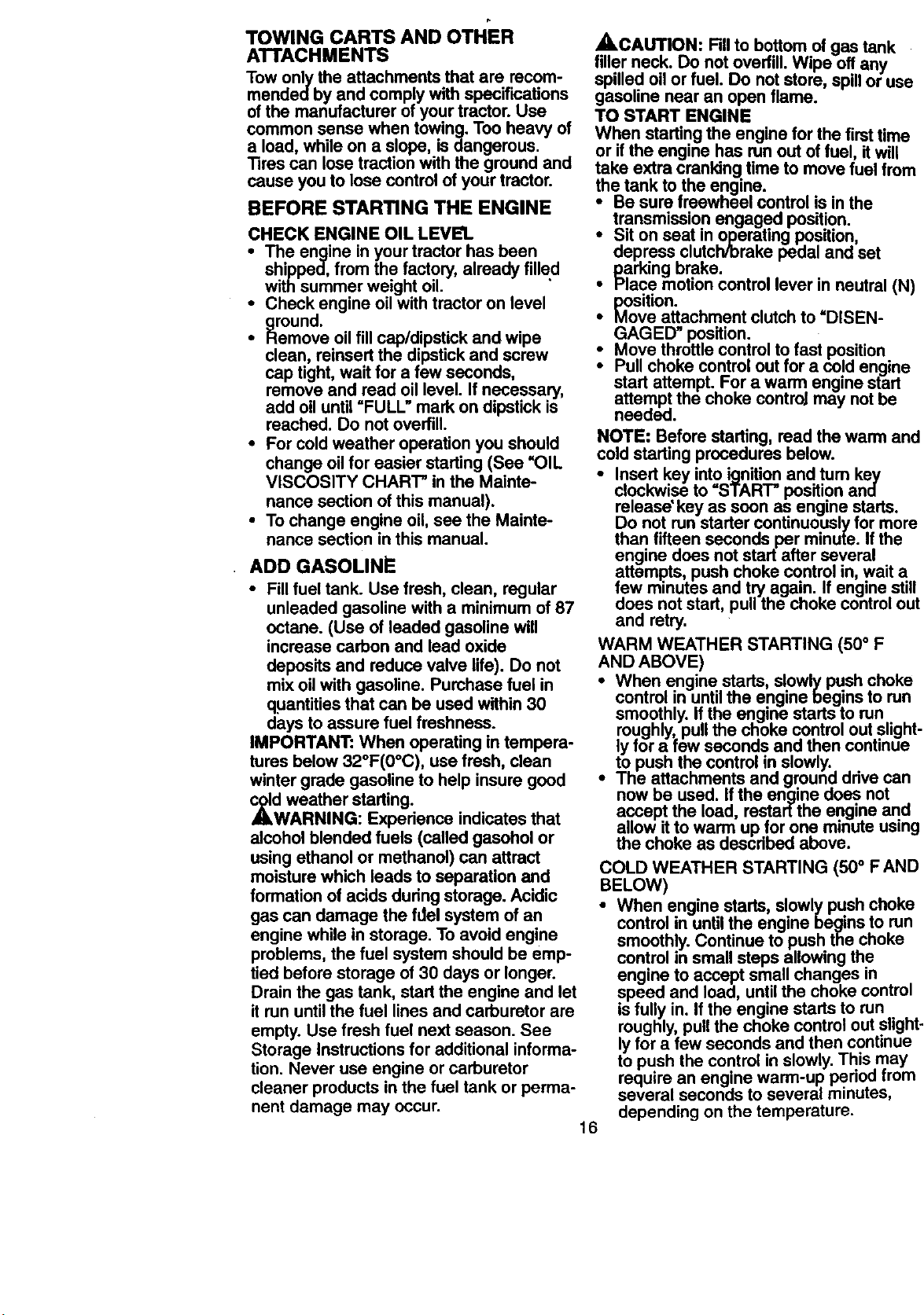
Clutch Lever
=Engaged"
Position
=Disengaged"
Position
Attachment
Lift
Lever High
Position
Low
Position
• Choose the slowest speed before start-
ing up or down hills.
• Avoid stopping or changing speed on
hills.
• If slowing is necessary, move throttle
control lever to slower position.
i f stopping is absolutely necessary, push
clutch/brake pedal quickly to brake posi-
tion and engage parking brake.
Move motion control lever to neutral (N)
position.
IMPORTANT: The motion control lever
does not return to neutral (N) position
when the clutch/brake pedal is depressed.
• To restart movement, slowly release
parking brake and clutch/brake pedal.
• Slowly move motion control lever to
slowest setting.
• Make all turns slowly.
TO TRANSPORT
When pushing or towingyour tractor, be
sure to disengage transmissionby placing
freewheel controlin freewheeling posi-
tion. Freewheel control is located at the
rear drawbar of tractor.
• Raise attachment liftto highest position
with attachment lift control.
• Pull freewheel control out and down into
the slot and release so it is held in the
disengaged position.
• Do not push or tow tractor at more than
two (2) MPH.
• To reengage transmission, reverse
above procedure.
NOTE: To protect hood from damage
when transportingyour tractor on a truck
or a trailer, be sure hood is closed and
secured to tractor. Use an appropriate
means of tying hood to tractor (rope, cord,
etc.).
15
TOWING CARTS AND OTHER
ATTACHMENTS
Tow only the attachments that are recom-
mendedby and comply with specifications
of the manufacturer of your tractor. Use
common sense when towing. Too heavy of
a load, while on a slope, is dangerous.
Tires can lose traction with the ground and
cause you to lose control of your tractor.
BEFORE STARTING THE ENGINE
CHECK ENGINE OIL LEVEL
• The engine in your tractor has been
shipped, from the factory, already filled
with summer weight oil.
• Chock engine oil with tractor on level
ground.
• Remove oil fill cap/dipstick and wipe
clean, reinsert the dipstick and screw
cap tight, wait for a few seconds,
remove and read oil level. If necessary,
add oil until "FULL" mark on dipstick is
reached. Do not overfill.
• For cold weather operation you should
change oil for easier starting (See =OIL
VISCOSITY CHART" in the Mainte-
nance section of this manual).
• To change engine oil, see the Mainte-
nance section in this manual.
ADD GASOLINE
• Fill fuel tank. Use fresh, clean, regular
unleaded gasoline with a minimum of 87
octane. (Use of leaded gasoline will
increase carbon and lead oxide
deposits and reduce valve life). Do not
mix oil with gasoline. Purchase fuel in
quantities that can be used within 30
days to assure fuel freshness.
IMPORTANT: When operating in tempera-
tures below 32°F(0°C), use fresh, clean
winter grade gasoline to help insure good
_dwAWeather starting.
RNING: Experience indicates that
alcohol blended fuels (called gasohol or
using ethanol or methanol) can attract
moisture which leads to separation and
formation of acids dudng storage. Acidic
gas can damage the fdel system of an
engine while in storage. To avoid engine
problems, the fuel system should be emp-
tied before storage of 30 days or longer.
Drain the gas tank, start the engine and let
it run until the fuel lines and carburetor are
empty. Use fresh fuel next season. See
Storage Instructions for additional informa-
tion. Never use engine or carburetor
cleaner products in the fuel tank or perma-
nent damage may occur.
16
ACAUTION: Fillto bottom of gas tank
fillerneck. Do not overfill. Wipe off any
spilled oil or fuel. Do not store, spillor use
gasoline near an open flame.
TO START ENGINE
When starting the engine for the first time
or ifthe engine has run out of fuel, itwill
take extra cranking time to move fuel from
the tank to the engine.
• Be sure freewheel control is in the
transmission engaged position.
i it on seat in operating position,
depress clutch/brake pedal and set
parking brake.
Place motioncontrol lever in neutral (N)
position.
• Move attachment clutch to =DISEN-
GAGED" position.
• Move throttlecontrol to fast position
Pull choke control out for a cold engine
start attempt. For a warm engine start
attempt the choke controJmay notbe
needed.
NOTE: Before starting, read the warm and
cold starting procedures below.
• Insert key intoignition and tum key
clockwise to =START"position and
release' key as soon as engine starts.
Do not runstarter continuouslyfor more
than fifteen seconds per minute. If the
engine does not start after several
attempts, push choke control in, wait a
few minutes and try again. If engine still
does not start, pull the choke control out
and retry.
WARM WEATHER STARTING (50° F
AND ABOVE)
• When engine starts, slowly pushchoke
control in untilthe engine begins to run
smoothly. If the engine starts to run
roughly,pull the choke control out slight-
lyfor a few seconds and then continue
to push the control in slowly.
• The attachments and ground ddve can
now be used. Ifthe enqine does not
accept the load restar[the engine and
allow it to warm up for one minute using
the choke as described above.
COLD WEATHER STARTING (50 ° F AND
BELOW)
• When engine starts, slowly push choke
control in until the engine begins to run
smoothly. Continue to push the choke
control in small steps allowing the
engine to accept small changes in
speed and load, until the choke control
is fully in. If the engine starts to run
roughly, pull the choke control out slight-
ly for a few seconds and then continue
to push the control in slowly. This may
require an engine warm-up period from
several seconds to several minutes,
depending on the temperature.
AUTOMATIC TRANSMISSION WARM-UP
• Before drivingthe unit incold weather,
the transmission should be warmed up
as follows:
• Be sure the tractor is on level ground.
• Place the motioncontrol lever in neu-
tral. Release the parking brake and
let the clutch/'orakeslowly retum to
operating position.
• Allow one minute fortraftsmission to
warm up. This can be done dudng the
engine warm upperiod.
• The attachments can be used during
the engine warm-up period after the
transmission has been warmed up and
may require the choke control t_epulled
out slightly.
NOTE: A highaltitude (above 3000 feet)
or in cold temperatures (below 32 F) the
carburetor fuel mixture may need to be
adjusted for best engine performance.
See "TO ADJUST CARBURETOR" in the
Service and Adjustments section ofthis
manual.
PURGE TRANSMISSION
A, CAUTION: Never engage or disen-
gage freewheel lever while the engine is
running.
To ensure proper operation and perfor-
mance, itis recommended that the trans-
mission be purged before operating tractor
for the firsttime. This procedure will
remove any trapped air inside the trans-
mission which may have developed during
shipping of your tractor.
IMPORTANT: Should your transmission
require removal for service or replace-
ment, it should be purged after reinstalla-
tion before operating the tractor.
• Place tractor safely on level surface with
engine off and parking brake set.
• Disengage transmission by placing free-
wheel control in freewheeling position
(See =TOTRANSPORT" in this section
Ofmanual).
• Sitting in the tractor seat, start engine.
After the engine is running, move throt-
tle control to slow position. With motion
control lever in neutral (N) position,
slowly disengage clutch/brake pedal.
• Move motion control lever to full forward
position and hold for five (5) seconds.
Move lever tofull reverse position and
holdfor five (5) seconds. Repeat this
procedure three (3) times.
NOTE: Duringthis procedure there will be
no movement of drive wheels. The air is
being removed from hydraulicdrive sys-
tem.
• Move motioncontrol lever to neutral (N)
position. Shut oft engine and set parking
brake.
• Engage transmissionby placingfree-
wheel control in drivingposition (See
*TO TRANSPORT" in this section of
manual).
• Sittingin the tractor seat, start engine.
After the engine is running, move throt-
tle controlto half (1/2) speed. With
motioncontrol lever in neutral (N) posi-
tion, slowly disengage clutch/brake
pedal.
• Slowly move motioncontrol lever for-
ward; after the tractor moves approxi-
mately five (5) feet, slowly move motion
control lever to reverse position.After
the tractor moves approximately five (5)
feet return the motioncontrol lever to
the neutral (N) position. Repeat this pro-
cedure with the motion control lever
three (3) times.
• Your tractor is now purged and ready for
normaloperation.
MOWING TIPS
• Tire chains cannot be used when the
mower housing isattached to tractor.
• Mower should be properlyleveled for
best mowing performance. See *TO
LEVEL MOWER HOUSING" in the
Service and Adjustments section ofthis
manu_,l.
• The left hand side of mower should be
used for trimming.
• Drive so that clippings are discharged
onto the area that has been cut. Have
the cut area to the fight ofthe tractor.
This will resultin a more even distribu-
tion of clippingsand more uniformcut-
ting.
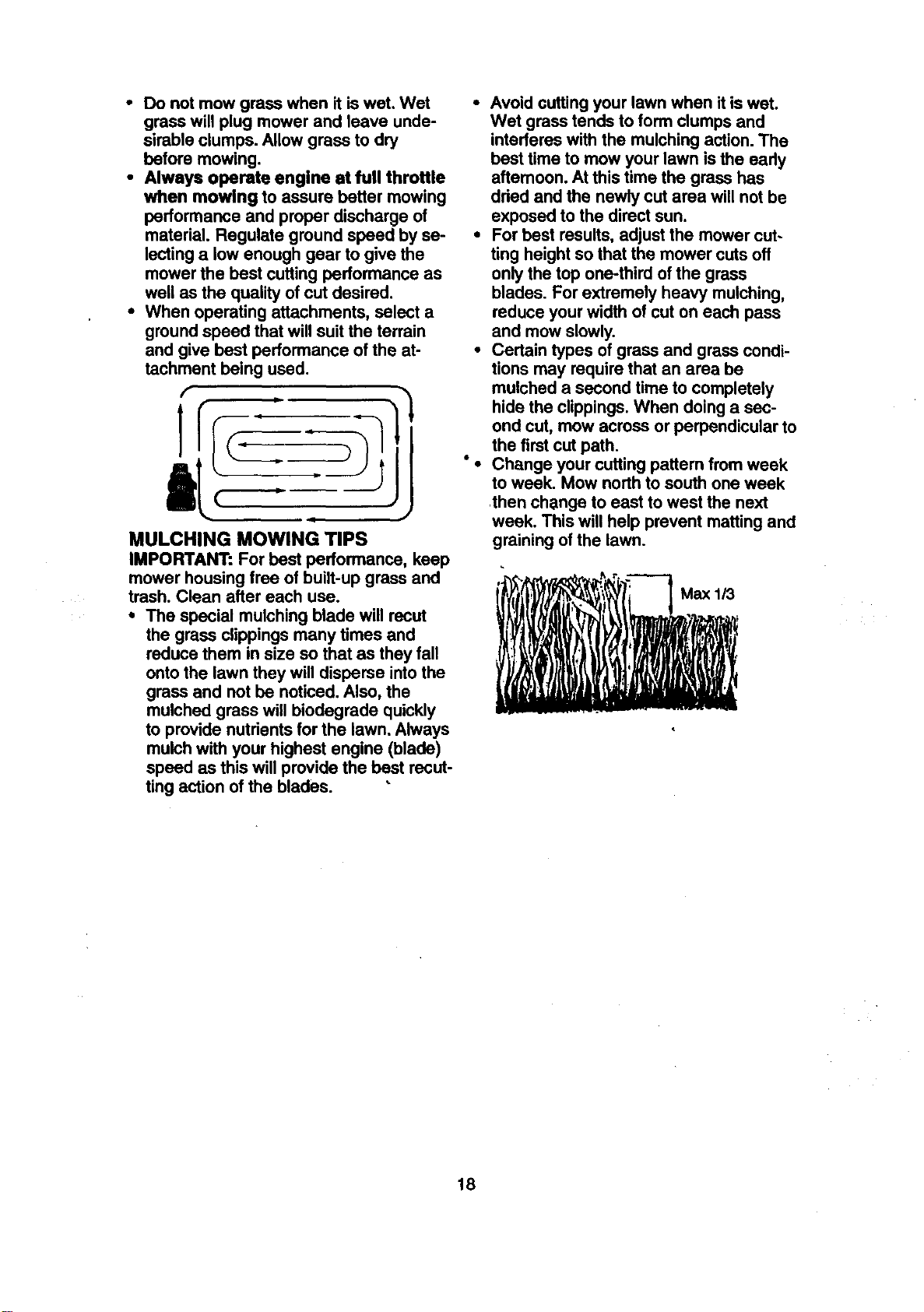
• When mowing large areas, start by turn-
ing to the rightso that clippingswill dis-
charge away from shrubs,fences, drive-
ways, etc. Afterone or two rounds, mow
in the opposite directionmaking left
hand tums until finished.
• Ifgrass is extremely tall, it should be
mowed twice to reduce load and possi-
ble fire hazard from dried clippings.
Make first cut relatively high;the second
to the desired height.
17
• Do not mow grass when it is wet, Wet
grass will plug mower and leave unde-
sirable clumps. Allow grass to dry
before mowing.
• Always operate engine st full throttle
when mowing to assure better mowing
performance and proper discharge of
material. Regulate ground speed by se-
lecting a low enough gear to give the
mower the best cutting performance as
well as the quality of cut desired.
• When operating attachments, select a
ground speed that will suit the terrain
and give best performance of the at-
tachment being used.
lr
MULCHING MOWING TIPS
IMPORTANT: For best performance, keep
mower housing free of built-up grass and
trash. Clean after each use.
The special mulching blade will recut
the grass clippings many times and
reduce them in size so that as they fall
onto the lawn they will disperse into the
grass and not be noticed. Also, the
mulched grass will biodegrade quickly
to provide nutrients for the lawn. Always
mulch with your highest engine (blade)
speed as this will provide the best recut-
ting action of the blades.
• Avoid cuttingyour lawn when it iswet.
Wet grass tends to form clumps and
interferes with the mulching action. The
best time to mow your lawn isthe eady
aftemoon. At this time the grass has
dded and the newly cut area will not be
exposed to the direct sun.
• For best results, adjust the mower cut-
ting height so that the mower cuts off
only the top one-third of the grass
blades. For extremely heavy mulching,
reduce your width of cut on each pass
and mow slowly.
• Certain types of grass and grass condi-
tions may require that an area be
mulched a second time to completely
hide the clippings. When doinga sec-
ond cut, mow across or perpendicular to
the first cut path.
• Change your cutting pattem fromweek
to week. Mow northto south one week
rthenchange to east to west the next
week. This will help prevent mattingand
graining of the lawn.
18
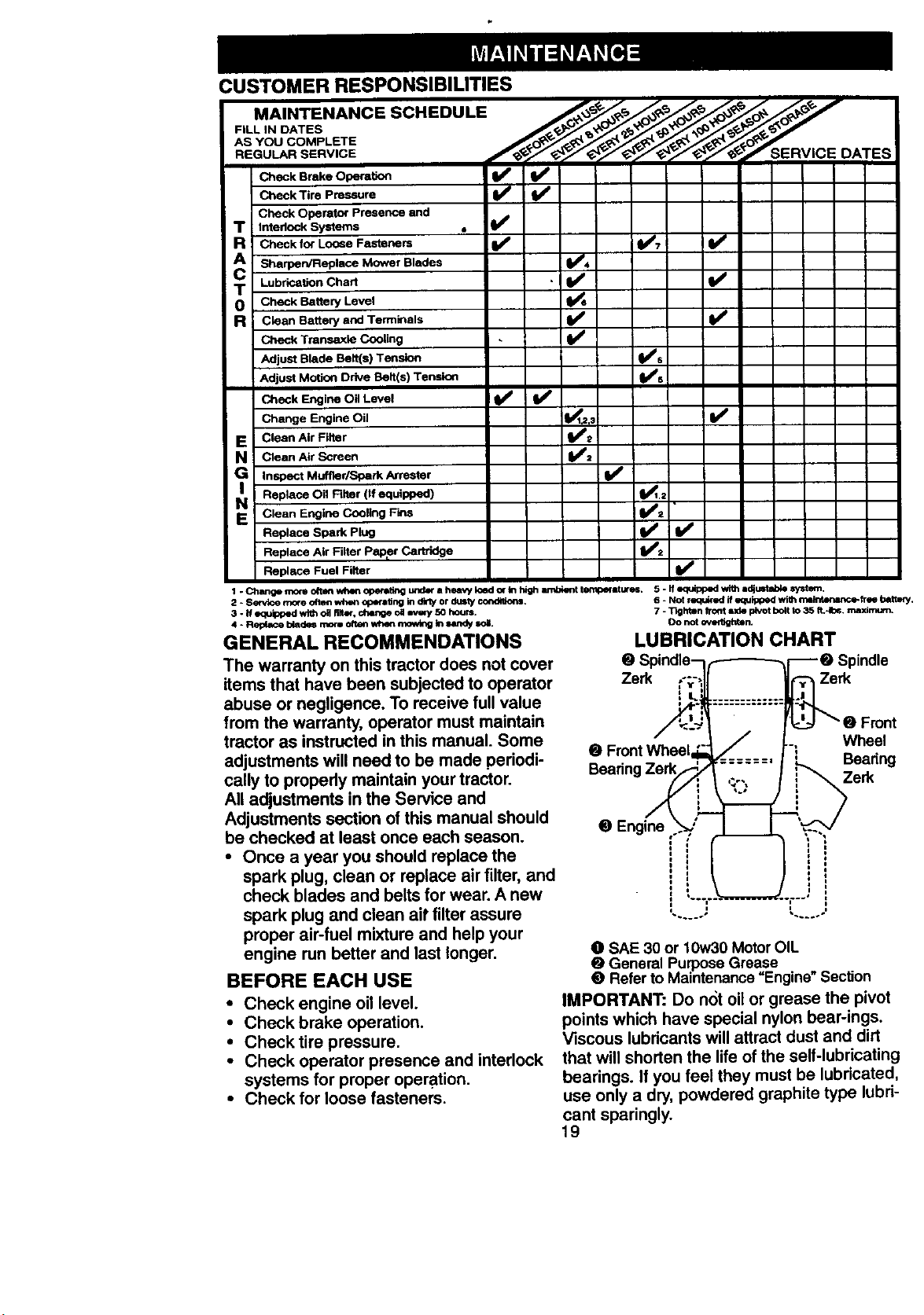
CUSTOMER RESPONSIBILITIES
MAINTENANCE SCHEDULE ____y_,o.j _
FILL IN DATES '_'J_,_ _
AS YOU COMPLETE /_€//_S_'RV
REGULAR SERVICE ICE DATES
Check Brake Opera_,o_
Check Tire Pressure
Check Operator Presence and
T Intedock Systems
R Check for Loose Fasteners
Sharpen/Replace Mower Blades
T Lubrication Chart
0 Check Battery Level
R c_eec Battery end Terminals
Check Transaxin Cooling
Adjust Blade Belt(s) Tension
: Adjust Moti_ Drive Bait(s) Tension
Check Engine Oil Level
Change Engine Oil
E Clean Air Filter
N Clean Air Screen
i1_ Inspect Mue_r/Spark Arrester
Replace Oil Alter (If equipped)
N Clean Engine Cooling Fins
Replace Spark Ping
Replace Air Filter Paler Cartridge
Replace Fuel Filter
1 -Changemo_o_lmwhlmoPecl_ngund_aheawIoadorklhighlmbienttemp_stures. 5-1fequ_opedwithidjL_e_esystem.
2 * Se_,,_e mo(e oftlm when opMaUng in dkly or dusty ©ond_ons. 6 * Not requ_ed if equipped with m=intenance-lree bettmy.
_,' V', V'
i/
• v'
v',
V',
)! -
3 .1f eq,_ped wltholl fllter,chen_ oa _e;y 5o hours.
4 - RelYmce blade4 more often _len _ k'l lmndy _,oi.
GENERAL RECOMMENDATIONS
The warranty on this tractor does not cover
items that have been subjected to operator
abuse or negligence. To receive full value
from the warranty, operator must maintain
tractor as instructed in this manual. Some
adjustments will need to be made periodi-
cally to propedy maintain your tractor.
All adjustments in the Service and
Adjustments section of this manual should
be checked at least once each season.
• Once a year you should replace the
spark plug, clean or replace air filter, and
check blades and belts for wear. A new
spark plug and clean air filter assure
proper air-fuel mixture and help your
engine run better and last longer.
BEFORE EACH USE
• Check engine oil level.
• Check brake operation.
• Check tire pressure.
• Check operator presence and interlock
systems for proper operation.
• Check for loose fasteners.
7 - Tighten froot i_de pivotboltto 35 ff.-10_,wmximum.
0o not _n.
LUBRICATION CHART
Spindle
Zerk Zerk
e
Beadn,
Wheel
Beadng
Ze_
O SAE 30 or 10w30 Motor OIL
General Purpose Grease
Refer to Maintenance =Engine" Section
IMPORTANT: Do not oil or grease the pivot
points which have special nylon bear-ings.
Viscous lubricants will attract dust and dirt
that will shorten the life of the self-lubricating
bearings. If you feel they must be lubricated,
use only a dry, powdered graphite type lubri-
cant sparingly.
19
TRACTOR
Alwaysobservesafetyruleswhenper-
forminganymaintenance.
BRAKEOPERATION
Iftractorrequiresmorethansix (6)feet
stoppingdistanceathighspeedin highest
gear,thenbrakemustbeadjusted.(See
"TO ADJUST BRAKE" in the Service and
Adjustments section of this manual).
TIRES
o
• Maintain proper air pressure in all tires
(See "PRODUCT SPECIFICATIONS"
on page 3 of this manual).
• Keep tires free of gasoline, oil, or insect
control chemicals which can harm rub-
ber.
• Avoid stumps, stones, deep ruts, sharp
objects and other hazards that may
cause tire damage.
NOTE: To seal tire punctures and prevent
flat tires due to slow leaks, tire sealant
may be purchased from your local parts
dealer. Tire sealant also prevents tire dry
rot and corrosion.
OPERATOR PRESENCE SYSTEM
Be sure that operator presence and inter-
lock systems are_orking prepedy. If your
tractor does not function as descdbed
below, repair the problem immediately.
• The engine should not start unless the
clutch/brake pedal isfully depressed
and attachment clutch control is in the
disengaged position.
• When the engine is running, any
attempt by the operator to leave the
seat without first setting the parking
brake should shut off the engine.
• When the engine is running and the
attachment clutch is engaged, any
attempt by the operator to leave the
seat should shut off the engine.
• The attachment clutch should never
operate unless the operator is inthe
seat.
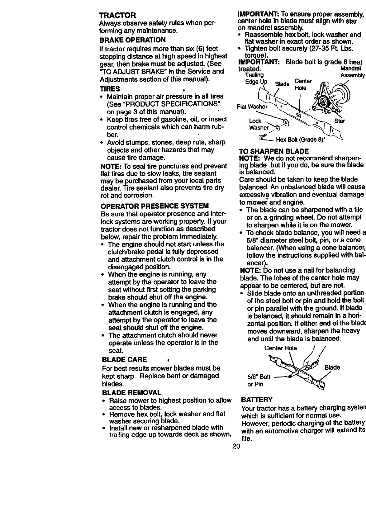
IMPORTANT: To ensure proper assembly,
center hole in blade must alugn with star
on mandrel assembly.
Reassemble hex bolt, lock washer and
flat washer in exact order as shown.
• Tighten bolt securely (27-35 Ft. Lbs.
torque).
IMPORTANT: Blade bolt is grade 8 heat
treated. Mandrel
Trailing Assembly
Edge Blade Center
Hole
Flat Washer
Lock Star
_--_ Hex Bolt(Grade 8)*
TO SHARPEN BLADE
NOTE: We do not recommend sharpen-
ingblade but if you do, be sure the blade
isbalanced.
Care should be taken to keep the blade
balanced. An unbalance¢, blade will cause
excessive vibration and eventual damage
to mower and engine.
• The blade can be sharpened with a file
or on a grinding wheel. Do not aRempt
to sharpen while it is on the mower.
• To check blade balance, you will need a
5/8" diameter steel bolt, pin, or a cone
balancer. (When using a cone balancer,
follow the instructions supplied with bal-
ancer).
NOTE: Do not use a nail for balancing
blade. The lobes of the center hole may
appear to be centered, but are not.
• Slide blade onto an unthreaded portion
of the steel bolt or pin and hold the bolt
or pin parallel with the ground. If blade
is balanced, itshould remain in a hori-
zontal position. If either end of the blade
moves downward, sharpen the heavy
end until the blade is balanced.
Center Hole
BLADE CARE
For best results mower blades must be
kept sharp, Replace bent or damaged
blades.
5/8" Bolt
or Pin
Blade
BLADE REMOVAL
• Raise mower to highest position to allow
access to blades.
• Remove hex bolt, lock washer and flat
washer securing blade.
• install new or resharpened blade with
trailing edge up towards deck as shown.
BATTERY
Your tractor has a battery charging system
which is sufficient for normal use.
However, pedodic charging of the battery
with an automotive charger will extend its
life.
2O
• Keep battery and terminals clean.
• Keep battery boltstight.
• Keep small vent holes open.
• Recharge at 6-10 amperes for I hour.
TO CLEAN BA'I-I'ERY AND TERMINALS
Corrosion and dirton the battery and ter-
minals can cause the battery to =leak"
power.
• Remove terminal guard.
• Disconnect BLACK battery cable first
then RED battery cable and remove
battery from tractor.
• Rinse the battery with plain water and
dry,
• Clean terminals and battery cable ends
with wire brush until bright.
• Coat terminals with grease or petroleum
jelly.
• Reinstall battery (See =REPLACING
BA'I-I'ERY" in the SERVICE AND
ADJUSTMENTS section of this manu-
al).
V-BELTS
Check V-belts for deterioration and wear
after 100 hours of operation and replace if
necessary. The belts are not adjustable.
Replace belts ifthey begin to slipfrom
wear.
TRANSAXLE C(_OLING
The transmission fan and coolingfins
should be kept clean to assure proper
cooling.
Do not attempt to clean fan or transmis-
sion while engine is runningor while the
transmission is hot.
• Inspect cooling fan to be sure fan
blades are intact and clean.
• Inspect cooling fins for dirt, grass clip-
pings and other materials. To prevent
damage to seals, do not usa com-
pressed air or highpressure sprayer to
clean cooling fins.
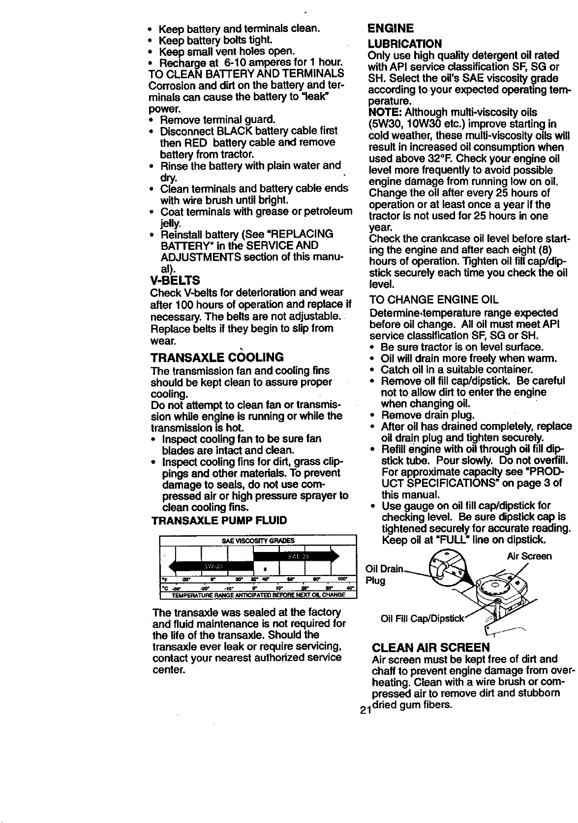
TRANSAXLE PUMP FLUID
The transaxle was sealed at the factory
and fluid maintenance is not required for
the life of the transaxle. Should the
transaxle ever leak or require servicing,
contact your nearest authorized service
center.
ENGINE
LUBRICATION
Only use high quality detergent oil rated
with API service classification SF, SG or
SH. Select the oil's SAE viscositygrade
according to your expected operating tem-
perature.
NOTE: Although multi-viscosity oils
(5W30, 10W30 etc.) improve starting in
cold weather, these multi-viscosityoils will
result in increased oilconsumption when
used above 32°R Check your engine oil
level more frequently to avoid possible
engine damage from running low on oil.
Change the oil after every 25 hours of
operation or at least once a year if the
tractor is not used for 25 hours inone
year.
Check the crankcase oil level before start-
ing the engine and after each eight (8)
hours of operation. Tighten oil fillcap/dip-
stick securely each time you check the oil
level.
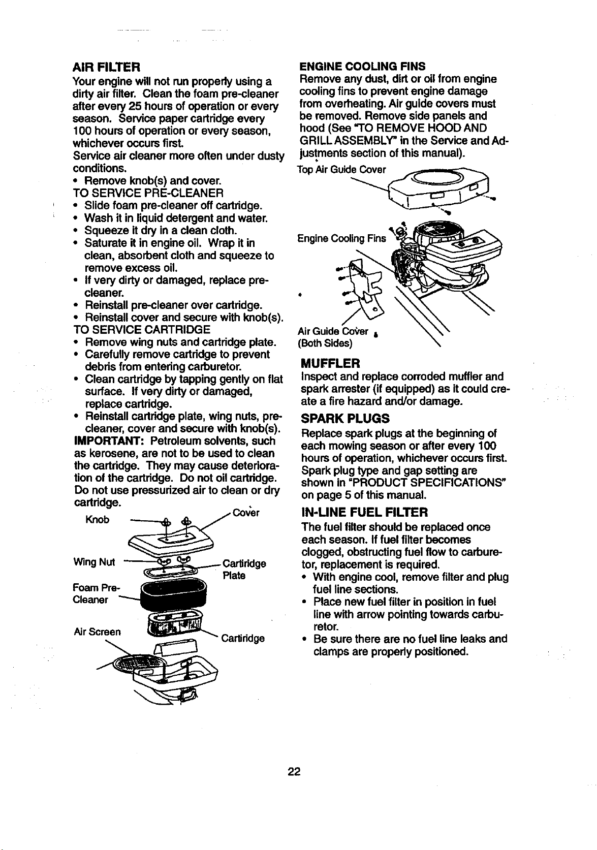
TO CHANGE ENGINE OIL
Determine,temperature range expected
before oil change. All oil must meet API
service classification SF, SG or SH.
• Be sure tractor is on level surface.
• Oil will drain more freely when warm.
• Catch oil in a suitable container.
• Remove oil fill cap/dipstick. Be careful
not to allow dirt to enter the engine
when changing oil.
• Remove drain plug.
• After oil has drained completely, replace
oil drain plug and tighten securely.
• Refill engine with oil through oil fill dip-
stick tube. Pour slowly. Do not overfill,
For approximate capacity see =PROD-
UCT SPECIFICATIONS" on page 3 of
this manual.
• Use gauge on oil fill cap/dipstick for
checking level. Be sure dipstick cap is
tightened securely for accurate reading.
Keep oil at =FULL" line on dipstick.
A_ Air Screen
Oil Dratn_._ _...._:_
Plug _
Oil Fill Cap/DipsUck_ _,_
CLEAN AIR SCREEN
Air screen must be kept free of dirt and
chaff to prevent engine damage from over-
heating. Clean with a wire brush or com-
pressed air to remove dirt and stubbom
21 dried gum fibers.
z
AIR FILTER
Your engine will not run propedy using a
dirty air filter. Clean the foam pre-cleaner
after every 25 hours of operation or every
season. Service paper cartridge every
100 hours of operation or every season,
whichever occurs first.
Service air cleaner more often under dusty
conditions.
• Remove knob(s) and cover.
TO SERVICE PRE-CLEANER
• Slide foam pre-cleaner off cartridge.
• Wash it in liquid detergent and water.
• Squeeze it dry in a clean cloth.
• Saturate it in engine oil. Wrap it in
clean, absorbent cloth and squeeze to
remove excess oil.
• If very dirty or damaged, replace pre-
cleaner.
• Reinstall pre-cleaner over cartridge.
• Reinstall cover and secure with knob(s).
TO SERVICE CARTRIDGE
• Remove wing nuts and cartridge plate.
• Carefully remove cartridge to prevent
debris from entedng carburetor.
• Clean cartridge by tapping gently on flat
surface. If very dirty or damaged,
replace cadddge.
• Reinstall cartridge plate, wing nuts, pre-
cleaner, cover and secure with knob(s).
IMPORTANT: Petroleum solvents, such
as kerosene, are not to be used to clean
the cartridge. They may cause deteriora-
tion of the cartridge. Do not oil cartridge.
Do not use pressurized air to clean or dry
cartddge.
Knob
Wing Nut
Foam Pre-
Cleaner
Plate
Air Screen
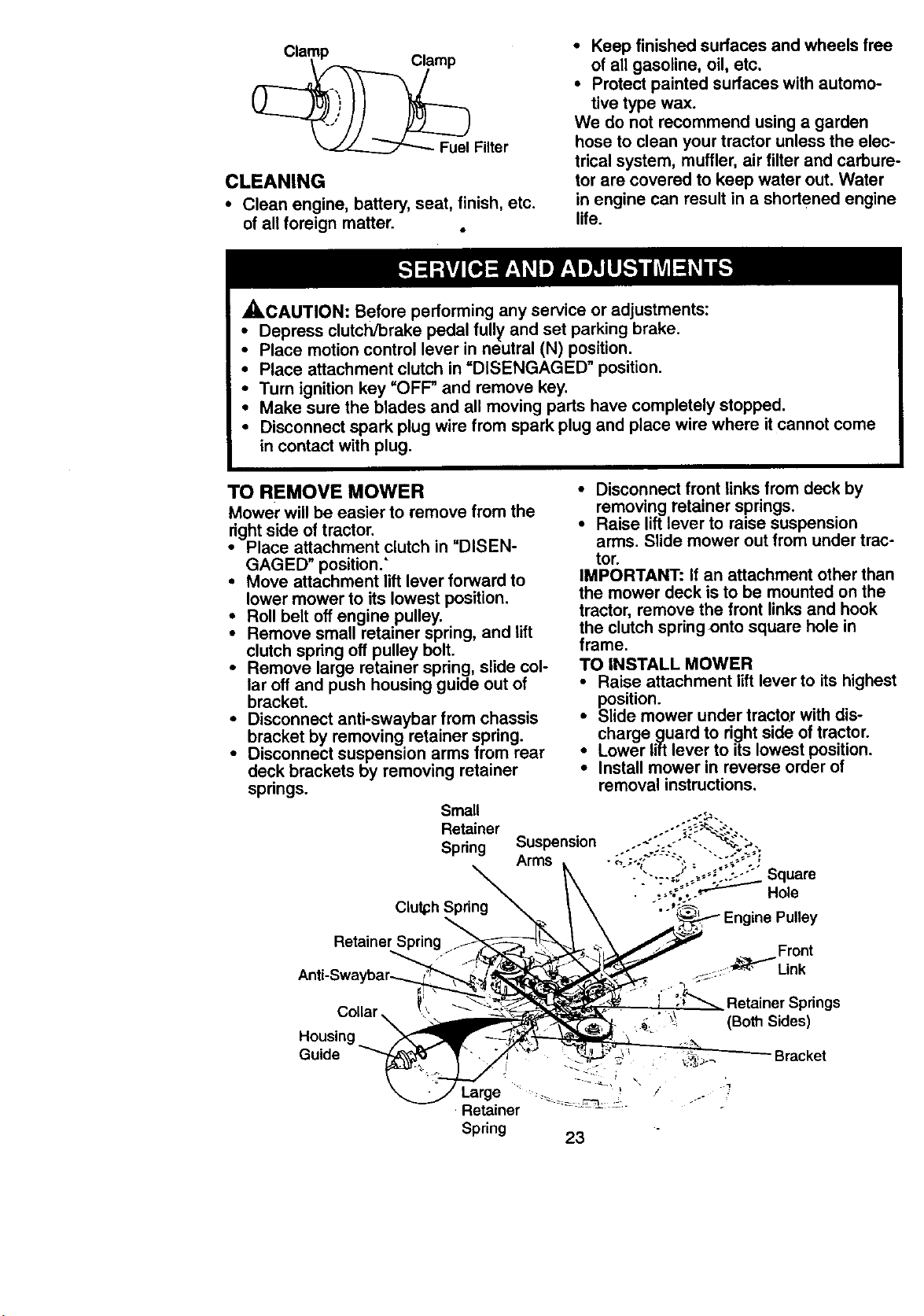
ENGINE COOLING FINS
Remove any dust, dirtor oil from engine
cooling fins to prevent engine damage
from overheating. Air guide covers must
be removed. Remove side panels and
hood (See "TO REMOVE HOOD AND
GRILL ASSEMBLY" in the Service and Ad-
justments section ofthis manual).
TopAir Guid_,,,
AirGuide Coger i
(Both Sides)
MUFFLER
Inspect and replace corroded muffler and
spark arrester (if equipped) as itcould cre-
ate a fire hazard and/or damage.
SPARK PLUGS
Replace spark plugs at the beginning of
each mowing season or after every 100
hours of operation, whichever occurs first.
Spark plug type and gap setting are
shown in =PRODUCT SPECIFICATIONS"
on page 5 of this manual.
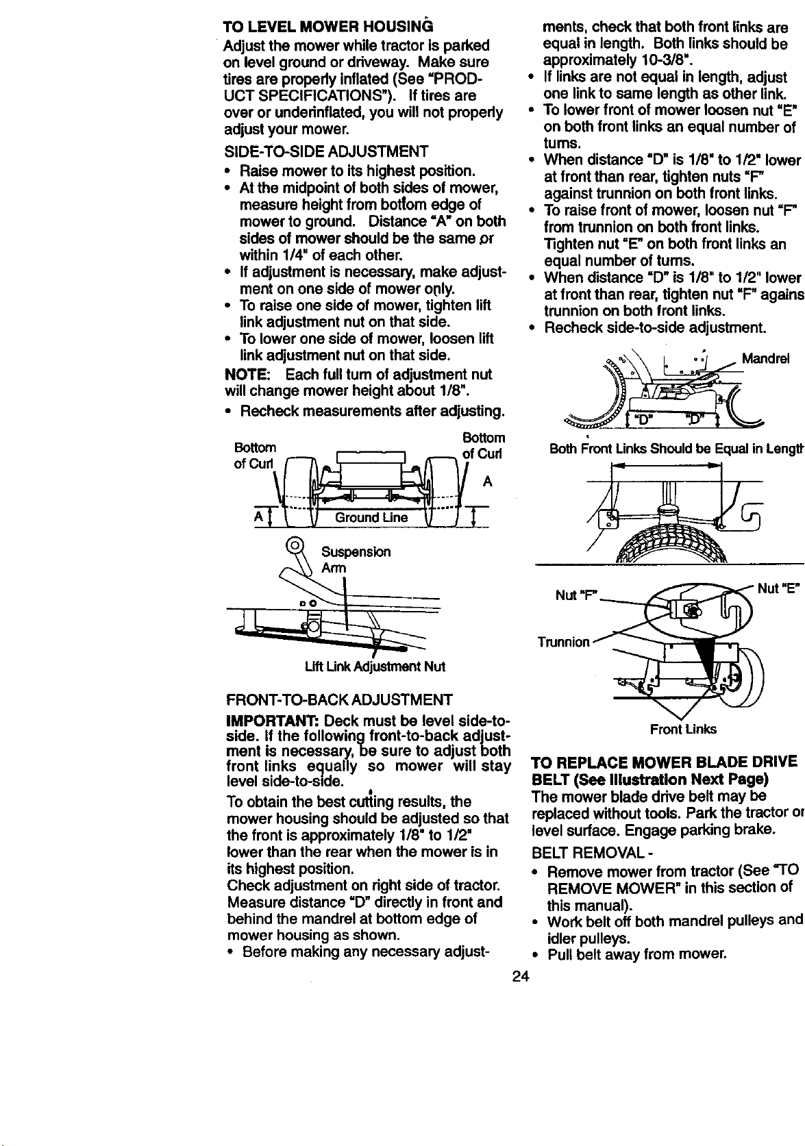
IN-UNE FUEL FILTER
The fuel filter shouldbe replaced once
each season. If fuel filter becomes
clogged, obstructing fuel flow to carbure-
tor, replacement is required.
• With engine cool, remove filter and plug
fuel line sections.
• Place new fuel filter in position in fuel
line with arrow pointing towards carbu-
retor.
• Be sure there are nofuel line leaks and
clamps are propedy positioned.
22
Clamp Clamp
Fuel Filter
CLEANING
• Clean engine, battery, seat, finish, etc.
of all foreign matter. .
• Keep finished surfaces and wheels free
of all gasoline, oil, etc.
• Protect painted surfaces with automo-
tive type wax.
We do not recommend using a garden
hose to clean your tractor unless the elec-
trical system, muffler, air filter and carbure-
tor are covered to keep water out. Water
in engine can result in a shortened engine
life.
_,CAUTION: Before performing any service or adjustments:
Depress clutch/brake pedal fully and set parking brake.
Place motion control lever in neutral (N) position.
• Place attachment clutch in =DISENGAGED" position.
• Turn ignition key =OFF" and remove key.
• Make sure the blades and all moving parts have completely stopped.
• Disconnect spark plug wire from spark plug and place wire where it cannot come
in contact with plug.
TO REMOVE MOWER
Mower will be easier to remove from the
right side of tractor.
• Place attachment clutch in "DISEN-
GAGED" position."
• Move attachment lift lever forward to
lower mower to its lowest position.
• Roll belt off engine pulley.
• Remove small retainer spring, and lift
clutch spring off pulley bolt.
• Remove large retainer spring, slide col-
lar off and push housing guide out of
bracket.
• Disconnect anti-swaybar from chassis
bracket by removing retainer spring.
• Disconnect suspension arms from rear
deck brackets by removing retainer
springs.
Small
Retainer
Spring
Clutph Spring
Retainer
Collar \
Housing
Guide
Large
•Retainer
Spring
• Disconnect front links from deck by
removing retainer springs.
• Raise lift lever to raise suspension
arms. Slide mower out from under trac-
tor.
IMPORTANT: If an attachment other than
the mower deck is to be mounted on the
tractor, remove the front links and hook
the clutch springonto square hole in
frame.
TO INSTALL MOWER
• Raise attachment lift lever to its highest
position.
• Slide mower under tractor with dis-
charge guard to right side of tractor.
• Lower lift lever to its lowest position.
• Install mower in reverse order of
removal instructions.
Suspension
Arms
Front
.... -p._t_"_Link
Retainer Springs
._ - (Both Sides)
Bracket
23
TO LEVEL MOWER HOUSINGi
Adjust the mower while tractor is parked
on level ground ordriveway. Make sure
tires are propody inflated (See =PROD-
UCT SPECIFICATIONS"). If tires are
over or underinflated, you will not properly
adjust your mower.
SIDE-TO-SIDE ADJUSTMENT
• Raise mower to its highest position.
• At the midpoint of both sides of mower,
measure height from bottom edge of
mower to ground. Distance =A" on both
sides of mower should be the same ,or
within 1/4" of each other.
• If adjustment is necessary, make adjust-
ment on one side of mower o01y.
• To raise one side of mower, tighten lift
link adjustment nut on that side.
• To lower one side of mower, loosen lift
link adjustment nut on that side.
NOTE: Each full tum of adjustment nut
will change mower height about 1/8".
• Recheck measurements after adjusting.
Bottom
Bottom
o,ou0 ,c:
Suspension
Arm
ments, check that both front links are
equal in length. Both linksshould be
approximately 10-3/8".
• If linksare not equal in length, adjust
one linkto same length as other link.
• To lower front of mower loosen nut "E"
on both front links an equal number of
tums.
• When distance =D" is 1/8" to 1/2" lower
at front than rear, tighten nuts=P
against trunnion on both front links.
• To raise front of mower, loosen nut =P
from trunnion on both front links.
Tighten nut =E"on both front links an
equal number of tums.
• When distance =D"is 1/8" to 1/2" lower
at front than rear, tighten nut "P against
trunnion on both front links.
• Recheck side-to-side adjustment.
_._\__Id rel° o
Both Front LinksShould be Equal in Length
Nut "P
Lift LinkAdjustmentNut
FRONT-TO-BACK ADJUSTMENT
IMPORTANT: Deck must be level side-to-
side. If the followingfront-to-back adjust-
ment is necessary, be sure to adjust both
front links equally so mower will stay
level side-to-side.
I
To obtain the best cutting results, the
mower housing should be adjusted so that
the front isapproximately 1/8" to 1/2"
lower than the rear when the mower is in
its highest position.
Check adjustment on right side of tractor.
Measure distance =D"directly infront and
behind the mandrel at bottom edge of
mower housing as shown.
• Before making any necessary adjust-
FrontUnks
TO REPLACE MOWER BLADE DRIVE
BELT (See lllustratlon Next Page)
The mower blade drive belt may be
replaced withouttools. Park the tractor on
level surface. Engage parking brake.
BELT REMOVAL-
• Remove mower from tractor (See "TO
REMOVE MOWER" in this section of
this manual).
• Work belt off both mandrel pulleys and
idler pulleys.
• Pull belt away from mower.
24
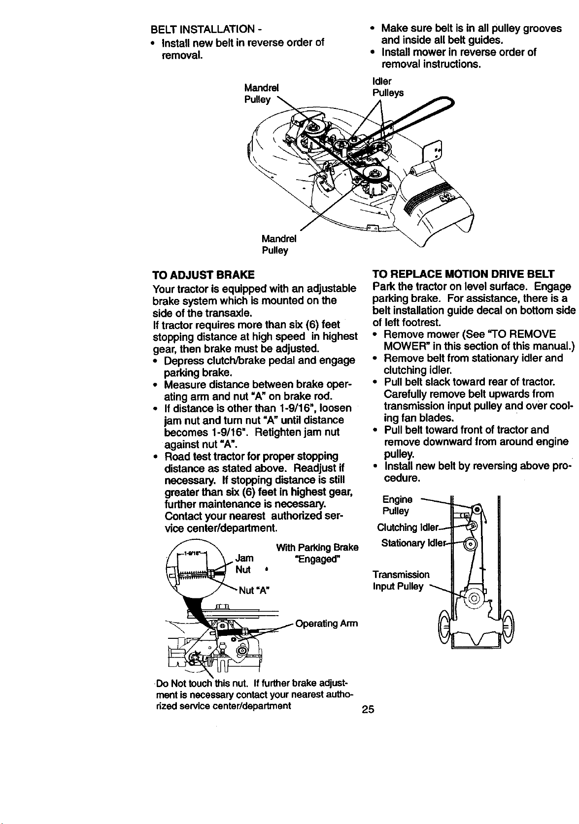
BELT INSTALLATION -
• Install new belt in reverse order of
removal.
Mandrel
• Make sure belt is in all pulley grooves
and inside allbelt guides.
• Install mower in reverse order of
removal instructions,
Idler
Pulleys
Mandrel
Pulley
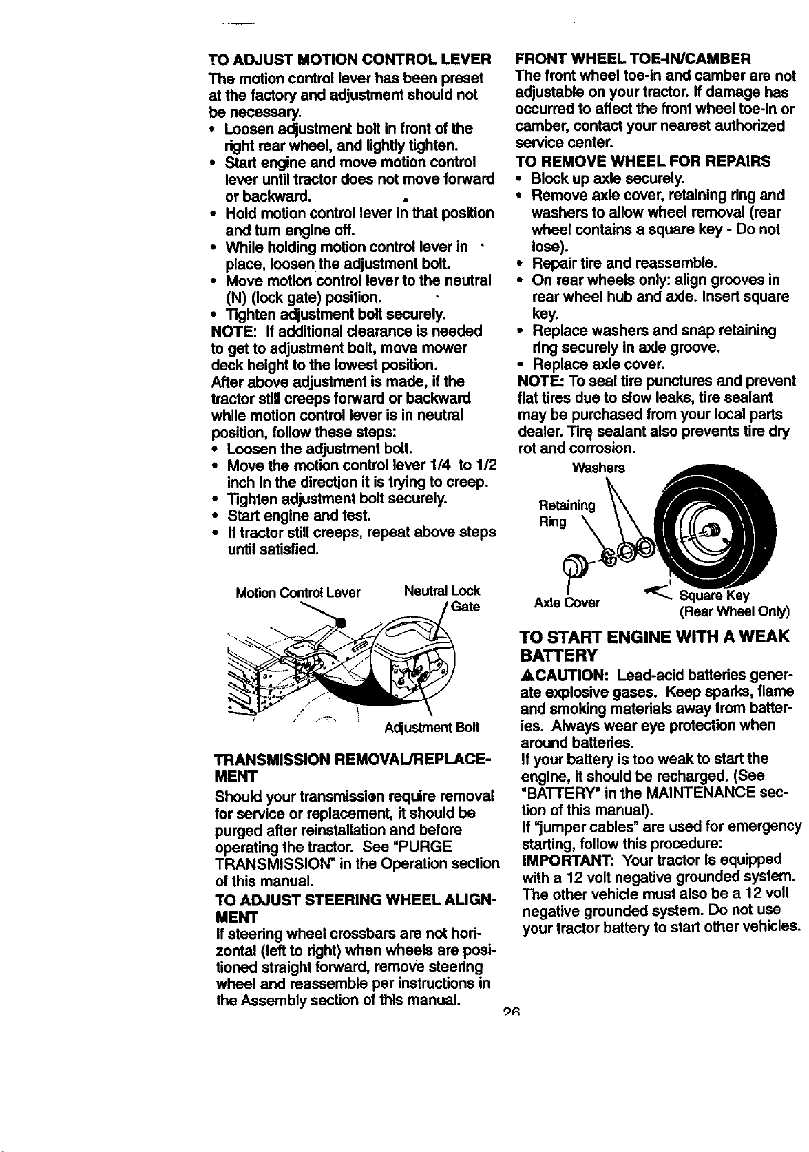
TO ADJUST BRAKE
Your tractor is equipped with an adjustable
brake system which is mounted on the
side of the transaxle.
If tractor requires more than six (6) feet
stopping distance at high speed in highest
gear, then brake must be adjusted.
• Depress clutch/brake pedal and engage
perking brake.
• Measure distance between brake oper-
ating arm and nut =A"on brake rod.
• If distance is other than 1-9/16", loosen
jam nut and tum nut =Anuntil distance
becomes 1-9/16". Retighten jam nut
against nut =A".
• Road test tractor for proper stopping
distance as stated above. Readjust if
necessary. If stopping distance is still
greater than six (6) feet in highest gear,
further maintenance is necessary.
Contact your nearest authorized ser-
vice center/department.
With Parking Brake
Jam =Engaged'
Nut *
Arm
TO REPLACE MOTION DRIVE BELT
Park the tractor on level surface. Engage
parking brake. For assistance, there is a
belt installationguide decal on bottom side
of left footrest.
• Remove mower (See "TO REMOVE
MOWER" in this section ofthis manual.)
• Remove belt from stationary idler and
clutching idler.
• Pull belt slack toward rear oftractor.
Carefully remove belt upwards from
transmission input pulleyand over cool-
ing fan blades.
• Pull belt toward front of tractor and
remove downward from around engine
pulley.
• Install new belt by reversing above pro-
cedure.
Engine
Pulley
ClutchingIdler-
Stationary Idler-
Transmission
Input Pulley
Do Not touchthis nut. Iffurther brake adjust-
ment is necessary contact your nearest autho-
rized service center/department 25
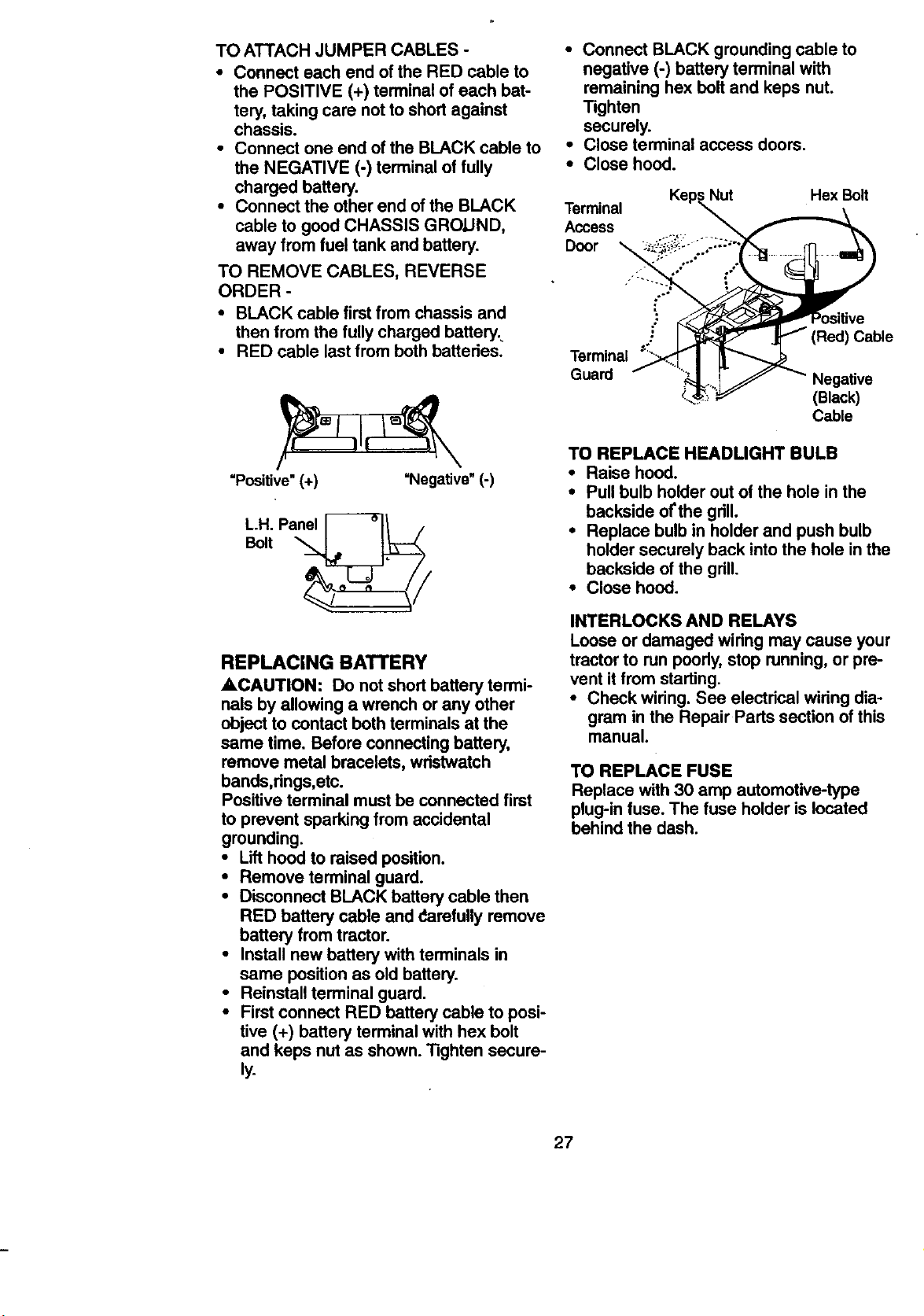
TO ADJUST MOTION CONTROL LEVER
The motion control lever has been preset
at the factory and adjustment should not
be necessary.
• Loosen adjustment bolt in front ofthe
rightrear wheel, and lightlytighten.
• Start engine and move motion control
lever untiltractor does not move forward
or backward.
• Hold motion controllever in that position
and tum engine oft.
• While holdingmotion control lever in
place, loosen the adjustment bolt.
• Move motioncontrol lever to the neutral
(N) (lock gate) position.
• Tighten adjustment belt securely.
NOTE: If additional clearance is needed
to get to adjustment belt, move mower
deck height to the lowest position.
After above adjustment is made, if the
tractor stillcreeps forward or backward
while motioncontrol lever is in neutral
position, follow these steps:
• Loosen the adjustment bolt.
• Move the motion control lever 114 to 1/2
inch in the direction it is trying to creep.
• Tighten adjustment boltsecurely.
• Start engine and test.
• If tractor stillcreeps, repeat above steps
untilsatisfied.
Motion Control Lever Neutral Lock
Gate
/ i .,,':?, i
AdjustmentBolt
TRANSMISSION REMOVAL/REPLACE-
MENT
Should your transmiss'uanrequire removal
for service or replacement, itshould be
purged after reinstallationand before
operating the tractor. See "PURGE
TRANSMISSION" in the Operation section
of this manual.
TO ADJUST STEERING WHEEL ALIGN-
MENT
Ifsteedng wheel crossbars are not hod-
zontal (left to dght)when wheels are posi-
tioned straightforward, remove steedng
wheel and reassemble per instructionsin
the Assembly section of this manual.
FRONT WHEEL TOE-IN/CAMBER
The front wheel toe-in and camber are not
adjustable on your tractor. If damage has
occurred to affect the front wheel toe-in or
camber, contact your nearest authorized
service center.
TO REMOVE WHEEL FOR REPAIRS
• Block up axle securely.
• Remove axle cover, retaining ring and
washers to allow wheel removal (rear
wheel contains a square key - Do not
lose).
• Repair tire and reassemble.
• On rear wheels only: align grooves in
rear wheel hub and axle. Insert square
key.
• Replace washers and snap retaining
ring securely in axle groove.
• Replace axle cover.
NOTE: To seal tire punctures and prevent
flat tires due to slow leaks, tire sealant
may be purchased from your local parts
dealer. Tire sealant also prevents tire dry
rot and corrosion.
--ni W:h A
Axle Cov'er _ Square Key
(Rear Wheel Only)
TO START ENGINE WITH A WEAK
BATTERY
ACAUTION: Lead-acid batteries gener-
ate explosive gases. Keep sparks, flame
and smoking matedals away from batter-
ies. Always wear eye protection when
around battedes.
If your battery is too weak to start the
engine, it should be recharged. (See
•BATTERY" in the MAINTENANCE sec-
tion of this manual).
If "jumper cables" are used for emergency
starting, follow this procedure:
IMPORTANT: Your tractor Is equipped
with a 12 volt negative grounded system.
The other vehicle must also be a 12 volt
negative grounded system. Do not use
your tractor battery to start other vehicles.
_R
TO ATTACH JUMPER CABLES -
• Connect each end of the RED cable to
the POSITIVE (+) terminal of each bat-
tery, taking care not to short against
chassis.
• Connect one end of the BLACK cable to
the NEGATIVE (-) terminal of fully
charged battery.
• Connect the other end of the BLACK
cable to good CHASSIS GROUND,
away from fuel tank and battery.
TO REMOVE CABLES, REVERSE
ORDER -
• BLACK cable first from chassis and
then from the fully charged battery.
• RED cable last from both batteries.
"Positive"(+) "Negative" (-)
L.H. Panel [_-_n /
Bolt
REPLACING BATTERY
ACAUTION: Do not short battery termi-
nals by allowing a wrench or any other
object to contact both terminals at the
same time. Before connecting battery,
remove metal bracelets, wristwatch
bands,rings,etc.
Positive terminal must be connected first
to prevent sparking from accidental
grounding.
• Lift hood to raised position.
• Remove terminal guard.
• Disconnect BLACK battery cable then
RED battery cable and darefully remove
battery from tractor.
• Install new battery with terminals in
same position as old battery.
• Reinstall terminal guard.
• First connect RED battery sable to posi-
tive (+) battery terminal with hex bolt
and keps nut as shown. Tighten secure-
ly.
• Connect BLACK grounding cable to
negative (-) battery terminal with
remaining hex bolt and keps nut.
Tighten
securely.
• Close terminal access doors.
• Close hood.
Terminal
Access
Door "_
; Nut Hex Bolt
Terminal _:"
Guard
Cable
Negative
(Black)
Cable
TO REPLACE HEADLIGHT BULB
• Raise hood.
• Pull bulb holder out of the hole in the
backside of'the grill.
• Replace bulb in holder and push bulb
holder securely back into the hole in the
backside of the grill.
• Close hood.
INTERLOCKS AND RELAYS
Loose or damaged wiring may cause your
tractor to run poorly, stop running, or pre-
vent it from starting.
• Check wiring. See electrical wiring dia-
gram in the Repair Parts section of this
manual.
TO REPLACE FUSE
Replace with 30 amp automotive-type
plug-in fuse. The fuse holder is located
behind the dash.
27

TOREMOVEHOODANDGRILLAS-
SEMBLY
• Raisehood.
Unsnap headlight wire connector.
• Stand in front of tractor.Grasp hood at
sides, tilttoward engine and liftoff of
tractor.
• To replace, reverse above procedures.
Hood
Headlight
\ ° Wire
Connector
Claml:
Quarter Circle
Choke Closed
Casing ClarnI
Screw
ENGINE
Maintenance, repair, or replacement of the
emission control devices and systems,
which are being done at the customers
expense, may be performed by any non-
road engine repair establishment or indi-
vidual. Warranty repairs must be per-
formed by an authorized engine manufac-
turer's service outlet.
TO ADJUST THROTTLE CONTROL
CABLE
The throttle control has been preset at the
factory and adjustment should not be nec-
essary. Check adjustment as described
below before loosening cable. If adjust-
ment is necessary, proceed as follows:
• With engine not running, move throttle
control lever to fast position.
• Check that swivel is against side of
quarter circle. If it is not, loosen cable
clamp screw and pull cable back until
swivel is against quarter circle. Tighten
cable clamp screw securely.
TO ADJUST CHOKE CONTROL
The choke control has been preset at the
factory and adjustment should not be nec-
essary. Check adjustment as descn_ed
below before loosening cable. If adjust-
ment is necessary, proceed as follows:
• With engine not running, move choke
control (located on dash panel) to full
choke position.
• Remove air cleaner cover, filter and car-
tridge plate to expose carburetor choke
(see =AIR FILTER" in the Customer
Responsibilities section of this manual).
• Choke should be closed. If it is not,
loosen casing clamp screw and move
choke cable until choke is completely
closed. Tighten casing clamp screw se-
curely.
• Reassemble air cleaner.
Choke Lever
TO ADJUST CARBURETOR
The carburetor has been preset at the fac-
tory and adjustment should not be neces-
sary. However, minor adjustment may be
required to compensate for differences in
fuel, temperature, altitude or load. Ifthe
carburetor does need adjustment, proceec
as follows:
In general, tuming the mixture screw In
(clockwise) decreases the supply offuel t¢
the engine giving a leaner fuel/air mixture.
Tuming the mixture screw out (counter-
clockwise) increases the supplyof fuel to
the engine giving a richer fuel/air mixture.
IMPORTANT: Damage to the needles and
the seats in carburetor may result ifscrew
is tumed in too tight.
PRELIMINARY SETTING
• Be sure you have a clean air filter, and
the throttle control cable and choke are
adjusted propedy (see above).
• With engine off tum idle mixture screw
in (clockwise) closing it finger tight and
then tum out (counterclockwise) 1-1/4
to 1-1/2 turns.
FINAL SETTING
• Start engine and allow to warm for five
minutes. Make final adjustments with
engine running and shift/motion control
lever in neutral (N) position.
• With throttle control lever in slow posi-
tion, hold throttle lever a_]ainst idle
speed screw and adjust idle speed
screw to obtain 1200 to 1400 RPM.
28
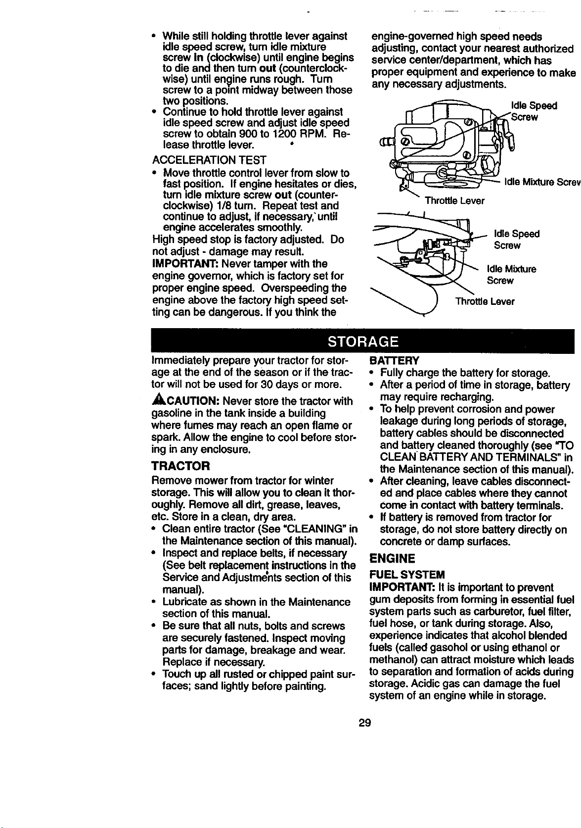
• While still holding throttle lever against
idle speed screw, tum idle mixture
screw in(clockwise) until engine begins
to die and then turn out (counterclock-
wise) until engine runs rough. Tum
screw to a point midway between those
two positions.
• Continue to hold throttle lever against
idle speed screw and adjust idle speed
screw to obtain 900 to 1200 RPM. Re-
lease throttle lever. •
ACCELERATION TEST
• Move throttle control lever from slow to
fast position. If engine hesitates or dies,
turn idle mixture screw out (counter-
clockwise) 118tum. Repeat test and
continue to adjust, if necessary,'until
engine accelerates smoothly.
High speed stop is factory adjusted. Do
not adjust - damage may result.
IMPORTANT: Never tamper with the
engine govemor, which isfactory set for
proper engine speed. Overspeeding the
engine above the factory high speed set-
tingcan be dangerous. If you think the
engine-govemed highspeed needs
adjusting, contact your nearest authorized
service center/department, which has
proper equipment and experience to make
any necessary adjustments.
e Mixture Scre_
Throttle Lever
_ldle Speed
crow
J_ Idle Mixture
_ Screw
Th_rrottleLever
immediately prepare your tractor for stor-
age at the end of the season or if the trac-
torwill not be used for 30 days or more.
_CAUTION: Never store the tractor with
gasoline inthe tank inside a building
where fumes may reach an open flame or
spark. Allow the engine to cool before stor-
ing in any enclosure.
TRACTOR
Remove mower from tractorfor winter
storage. This willallow you to clean itthor-
oughly. Remove all dirt, grease, leaves,
etc. Store ina clean, dry area.
• Clean entire tractor (See =CLEANING" in
the Maintenance section of this manual).
• Inspect and replace belts, if necessary
(See belt replacement instructionsin the
Service and Adjustments section of this
manual).
• Lubricate as shown in the Maintenance
section of this manual.
• Be sure that all nuts, bolts and screws
are securely fastened. Inspect moving
pads for damage, breakage and wear.
Replace if necessary.
• Touch up all rusted or chipped paint sur-
faces; sand lightlybefore painting.
BA'I'I'ERY
• Fullycharge the battery for storage.
• After a period of time in storage, battery
may require recharging.
• To help prevent corrosionand power
leakage duringlong periods of storage,
battery cables should be disconnected
and battery cleaned thoroughly(see "TO
CLEAN BATTERY AND TERMINALS" in
the Maintenance section of this manual).
• After cleaning, leave cables disconnect-
ed and place cables where they cannot
come in contact with battery terminals.
• Ifbattery is removed from tractor for
storage, do not store battery directlyon
concrete or damp surfaces.
ENGINE
FUEL SYSTEM
IMPORTANT: It is impertant to prevent
gum deposits from forming in essential fuel
system parts such as carburetor, fuel filter,
fuel hose, or tank during storage. Also,
experience indicates that alcohol blended
fuels (called gasohol or using ethanol or
methanol) can attract moisture which leads
to separation and formation of acids dudng
storage. Acidic gas can damage the fuel
system of an engine while in storage.
29
• Drain the fuel tank.
• Start the engine and let it run until the
fuel lines and carburetor are empty.
• Never use engine or carburetor cleaner
products in the fuel tank or permanent
damage may occur.
• Use fresh fuel next season.
NOTE: Fuel stabilizer is an acceptable
altamaUve in minimizingthe formation of
fuel gum deposits duringstorage. Add sta-
bilizer to gasoline in fuel tank or storage
container. Always follow the mix ratio
found on stabilizer container. Run engine
at least 10 minutes after adding stabilizer
to allow the stabilizer to reach the carbure-
tor. Do not drain the gas tank and'carbure-
tor ifusing fuel stabilizer.
ENGINE OIL
Drain oil (with engine warm) and replace
with clean engine oil. (See =ENGINEnin
the Maintenance section of this manual).
CYLINDER(S)
• Remove spark plug(s).
• Pour one ounce of oil through spark plug
hole(s) intocylin_ler(s).
•Tum ignitionkey to =START" positionfor
a few seconds to distribute oil.
• Replace with new spark plug(s).
OTHER
• Do not store gasoline from one season
to another.
• Replace your gasoline can if itstartsto
rust. Rust and/or dirt in your gasoline will
cause problems.
• If possible, store your tractor indoors
and cover it tO give protection from dust
and dirt.
• Cover your tractor with a suitable protec-
tive cover that does not retain moisture.
Do not use plastic. Plastic cannot
breathe, which allows condensation to
form and cause your tractor to rust.
IMPORTANT: Never cover tractor while
engine and exhaust areas are stillwarm.
3O
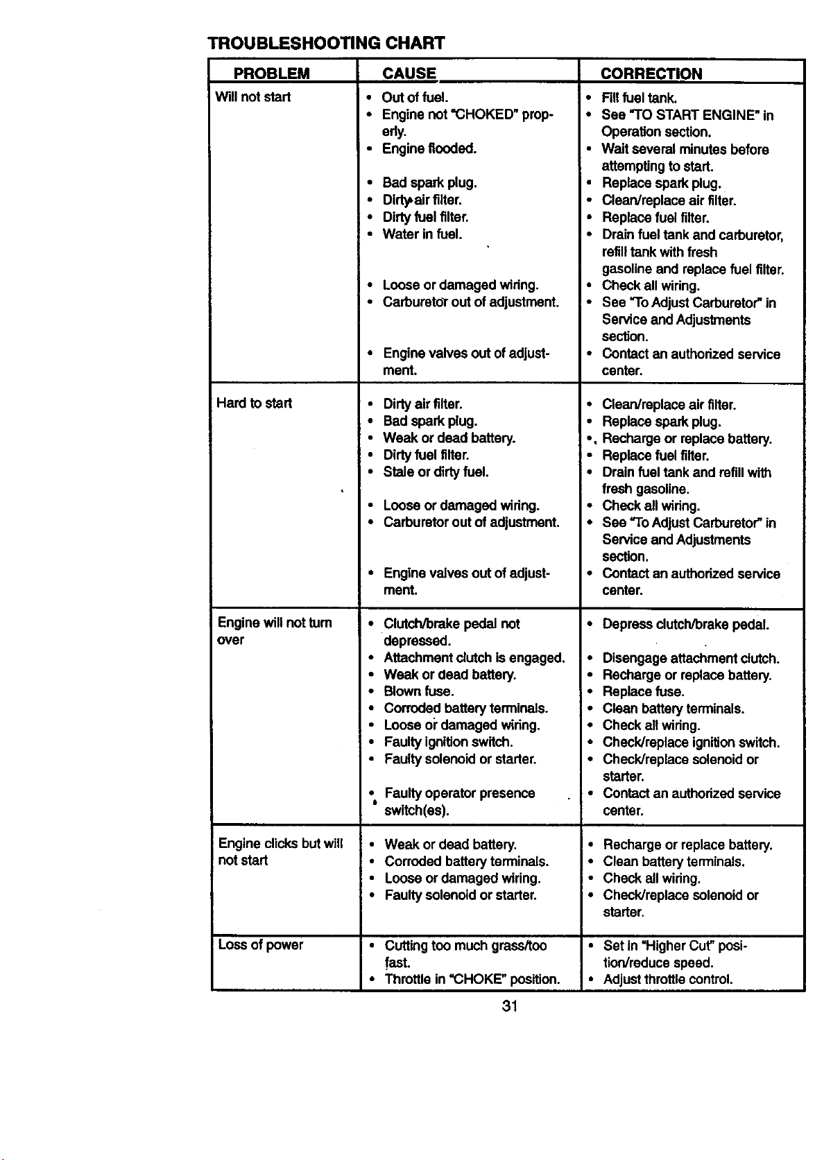
TROUBLESHOOTING CHART
PROBLEM
Will not start
Hard to start
Engine willnot turn
over
Engine dicks but will
not start
Loss of power
CAUSE
• Out of fuel.
• Engine not'CHOKED" prop-
erly.
• Engine flooded.
• Bad spark plug.
• Dirty,air filter.
• Dirtyfuel filter.
• Water in fuel.
• Loose or damaged wiring.
• Carbureto_rout of adjustment.
Engine valves out of adjust-
ment.
• Dirty air filter.
• Bad spark plug.
• Weak or dead battery.
• Dirty fuel tilter.
• Stale or dirty fuel.
• Loose or damaged wiring.
• Carburetor out of adjustment.
• Engine valves out of adjust-
ment.
• Clutch/brake pedal not
depressed.
• Attachment clutchis engaged.
• Weak or dead battery.
• Blown fuse.
• Corroded battery terminals.
• Loose oi"damaged widng.
• Faulty ignitionswitch.
• Faulty solenoid or starter.
• Faulty operator presence
6
switch(as).
• Weak or dead battery.
• Corroded battery terminals.
• Loose or damaged widng.
• Faulty solenoid or starter.
• Cutting too much grass/too
fast.
• Throttle in =CHOKE" position.
CORRECTION
• Fillfuel tank.
• See "TO START ENGINE" in
Operation section.
• Walt several minutes before
attempting to start.
• Replace spark plug.
• Clean/replace air tilter.
• Replace fuel tilter.
• Drain fuel tank and carburetor,
refilltank with fresh
gasoline and replace fuel filter.
• Check all wiring.
• See "ToAdjust Carburetor" in
Service and Adjustments
section.
• Contact an authorized service
center.
• Clean/replace air filter.
• Replace spark plug,
• , Recharge or replace battery.
• Replace fuel filter.
• Drain fuel tank and refill with
fresh gasoline.
• Check all wiring.
• See -To Adjust Carburetor"in
Service and Adjustments
section.
• Contact an authorized service
center.
• Depress clutch/brake pedal.
• Disengage attachment clutch.
• Recharge or replace battery.
• Replace fuse.
• Clean battery terminals.
• Check all wiring.
• Check/replace ignitionswitch.
• Check/replace solenoid or
starter.
• Contact an authorized service
center.
• Recharge or replace battery.
• Clean battery terminals.
• Check all wiring.
• Check/replace solenoid or
starter.
• Set in "Higher Cut"posi-
tion/reduce speed.
• Adjustthrottle control.
31
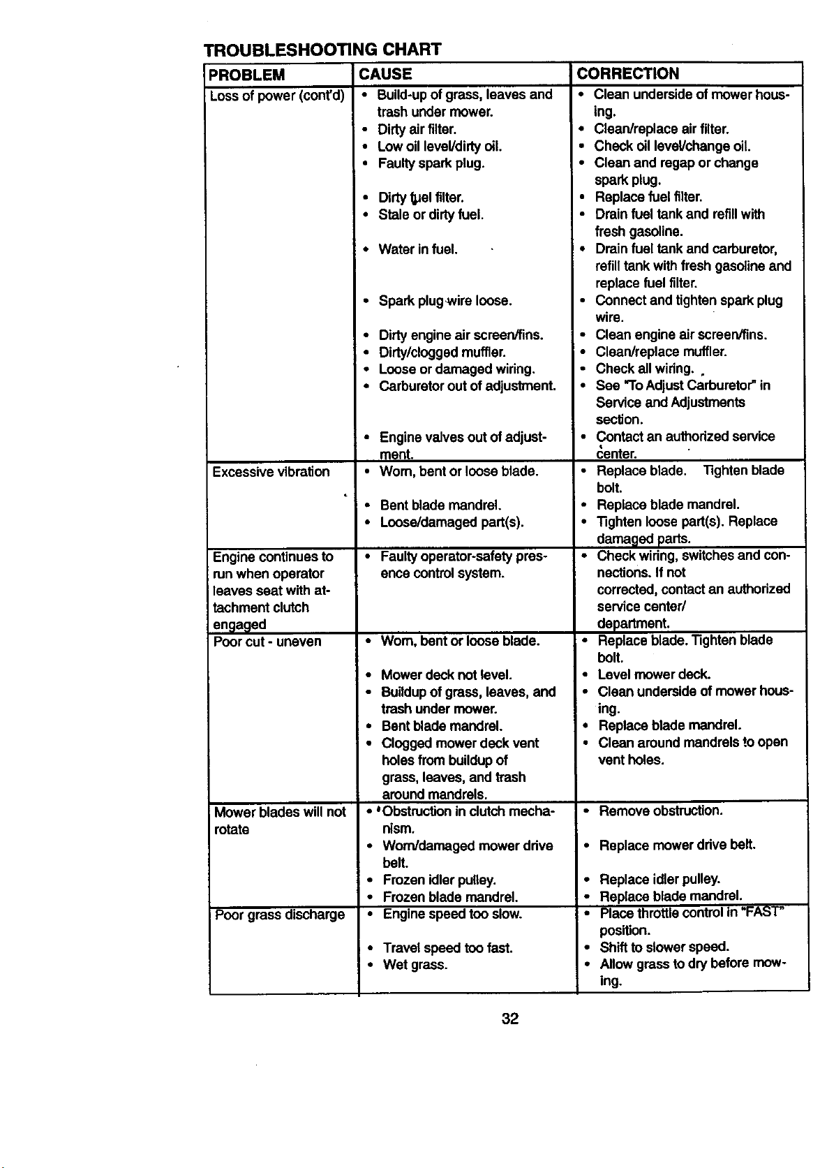
tROUBLESHOOTING CHART
PROBLEM
Loss of power (cont'd)
CAUSE
• Build-upof grass, leaves and
trash under mower.
• Dirtyair filter.
• Low oillevel/dirty oil.
• Faultyspark plug.
• Dirty_el filter.
• Stale or dirtyfuel.
• Water in fuel.
• Spark plugwire loose.
Excessive vibration
Engine continues to
runwhen operator
leaves seat with at-
tachment clutch
engaged
Poor cut - uneven
Mower blades will not
rotate
Poor grass discharge
• Dirtyengine air screen/fins.
• Dirty/cloggedmuffler.
• Looseor damaged wiring.
• Carburetorout of adjustment.
• Engine valves out of adjust-
ment.
• Worn, bent or loose blade.
• Bent blade mandrel.
• Loose/damaged part(s).
• Faultyoperator-safety pres-
ence controlsystem.
• Worn, bent or loose blade.
• Mower deck not level.
• Buildupof grass, leaves, and
trash under mower.
• Bent blade mandrel.
• Clogged mower deck vent
holes from buildupof
grass, leaves, and trash
around mandrels.
• 'Obstruction in clutch mecha-
nism.
• Worn/damaged mower ddve
belt.
• Frozen idler pulley.
• Frozen blade mandrel.
• Engine speed too slow.
• Travel speed too fast.
• Wet grass.
CORRECTION
• Clean underside of mower hous-
ing.
• Clean/replace air filter.
• Check oil level/change oil.
• Clean and regap or change
spark plug.
• Replace fuel filter.
• Drain fuel tank and refillwith
fresh gasoline.
• Drain fuel tank and carburetor,
refill tank with fresh gasoline and
replace fuel filter.
• Connect and tighten spark plug
wire.
• Clean engine air screen/fins.
• Clean/replace muffler.
• Check all widng, o
• See "ToAdjust Carburetor" in
Service and Adjustments
section.
• Contact an authorized service
_enter.
• Replace blade. Tightenblade
bolt.
• Replace blade mandrel.
• Tighten loose part(s). Replace
damagedparts.
• Check wiring,switches and con-
nections. If not
corrected, contactan authorized
service center/
department.
• Replace blade. Tighten blade
bolt.
• Level mower deck.
• Clean underside of mower hous-
ing.
• Replace blade mandrel.
• Clean around mandrels1.oopen
vent holes.
• Remove obstruction.
• Replace mower ddve belt.
• Replace idlerpulley.
• Replace blade mandrel.
• Place throttle controlin "FAST"
position.
• Shift to slowerspeed.
• Allow grass to dry before mow-
ing.
32
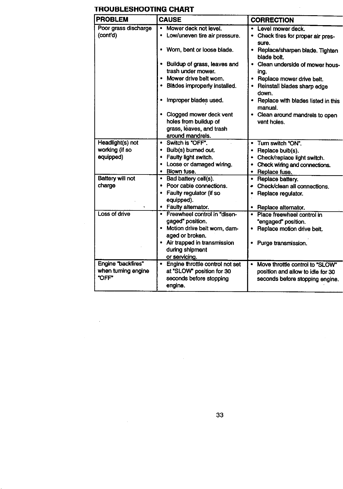
TROUBLESHOOTING CHART
PROBLEM CAUSE
Poor grass discharge • Mower deck not level.
(cont'd) • Low/unevan tire air pressure.
•Wom, bent or loose blade.
• Buildup ofgrass, leaves and
trash under mower.
• Mower drive belt worn.
• Blades impropedy installed.
• Improper blades used.
Headlight(s) not
working (ifso
equipped)
Battery willnot
charge
Loss ofdrive
Engine "backfires" •
when turning engine
"OFF"
• Clogged mower deck vent
holes from buildupof
grass, I_aves, and trash
around mandrels.
• Switch is"OFF".
• Bulb(s) bumed out.
• Faulty lightswitch.
• Loose or damaged widng.
• Blown fuse.
• Bad battery cell(s).
• Poor cable connections.
• Faulty regulator (ifso
equipped).
• Faulty altemator.
• Freewheel controlin =disen-
gaged" position.
• Motion drive belt worn, dam-
aged or broken.
• Airtrapped in transmission
dudng shipment
or servicing.
Engine throttlecontrol not set
at "SLOW" positionfor 30
seconds before stopping
engine.
CORRECTION
• Level mower deck.
• Check tires for properair pres-
sure.
• Replace/sharpan blade, "l]ghtan
blade bolt.
• Glean underside of mower hous-
ing.
• Replace mowerddve belt.
• Reinstall blades sharp edge
down.
• Replace with blades listedin this
manual.
• Clean around mandrels to open
vent holes.
•Tum switch "ON".
• Replace bulb(s).
• Check/replace lightswitch.
• Check widngand conneclfoos.
• Replace fuse.
• Replace battery.
,, Check/clean allconnections.
• Replace regulator.
• Replace alternator.
• Place freewheel controlin
=engaged"position.
• Replace motiondrivebelt.
• Purge transmission.
• Move throttle control to =SLOW"
position and allow to idle for 30
seconds before stopping engine.
33

NOTES
34
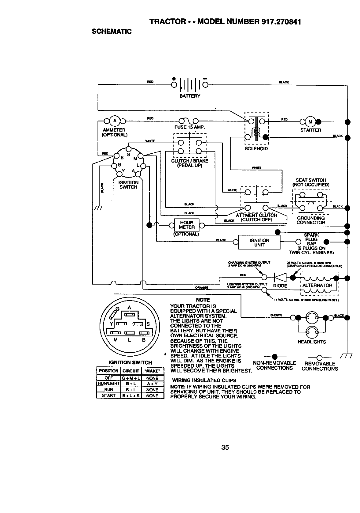
SCHEMATIC
TRACTOR - - MODEL NUMBER 917.270841
BATrERY
__ RED
AMMETER
(OPTIONAL)
FUSE15AMP.
• BLACK _ .......
SLACK (CLUTCH OFF) GROUNDING
_j CONNECTOR
m.ACK iGNITION PLUG
UNIT GAP
I (2 PLUGS ON
TWIN CYL ENGINES)
IGNITION SWITCH
PO61TION CIRCUrr .'MAKE"
OFF G+M+L NONE
START B + L + S NONE
RUN/UGHT B+L A+Y
RUN B + L NONE
ORANGE
NOTE
_ SYSI"I_I OUII_UT 2eVOLTll i,C NN, e :N¢ORpM
I N,IP OC II lmlO RPM {I:_._RGING81'STEMOISCONNECTEO)
YOUR TRACTOR IS
EQUIPPED WITH A SPECIAL
ALTERNATOR SYSTEM.
THE LIGHTS ARE NOT
CONNECTED TO THE
BATTERY, BUT HAVE THEIR
OWN ELECTRICAL SOURCE.
BECAUSE OF THIS, THE
BRIGHTNESS OF THE LIGHTS
WILL CHANGE WITH ENGINE
SPEED. AT IDLE THE LIGHTS
WILL DIM. ASTHE ENGINE IS
SPEEDED UP, THE LIGHTS CONNECTIONS
WILL BECOME THEIR BRIGHTEST.
HEADLIGHTS
--e-- O F,
NON-REMOVABLE REMOVABLE
CONNECTIONS
WIRING INSULATED CUPS
NOTE: IF WIRING INSULATED CLIPS WERE REMOVED FOR
SERVICING OF UNIT, THEY SHOULD BE REPLACED TO
PROPERLY SECURE YOUR WIRING.
35
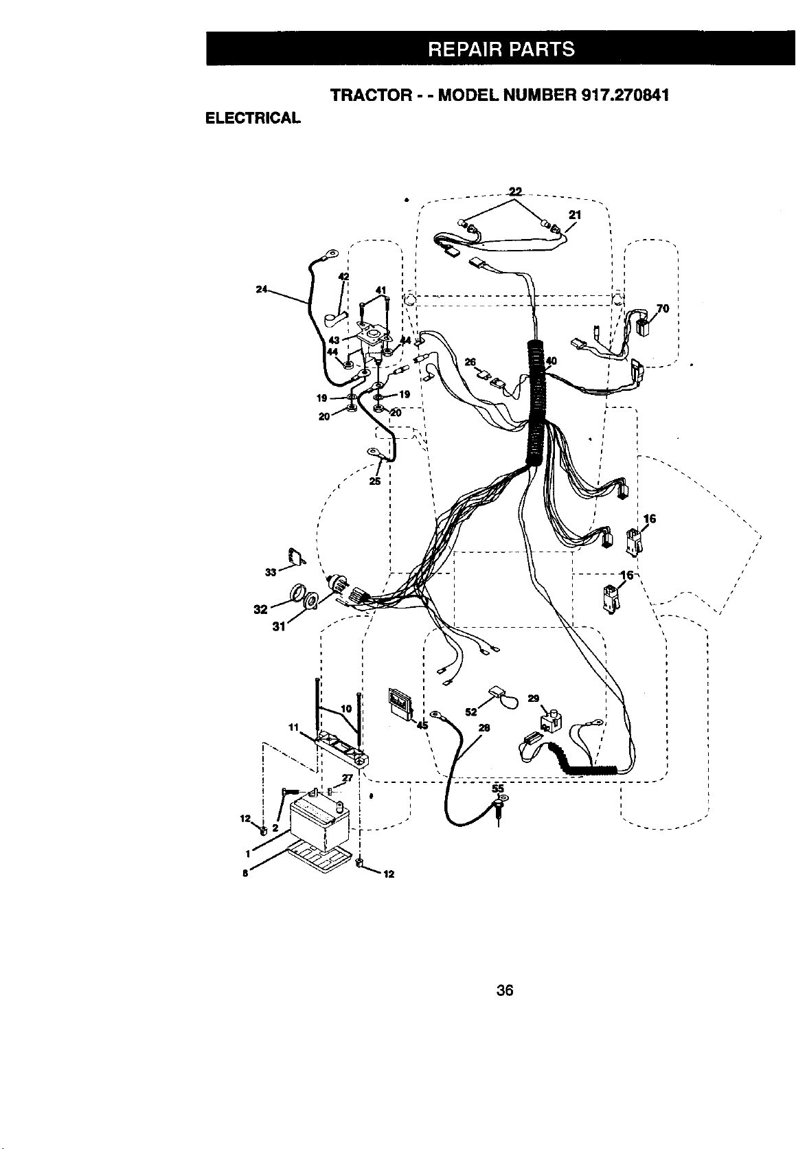
ELECTRICAL
TRACTOR - - MODEL NUMBER 917.270841
F
n
41
I
h
36
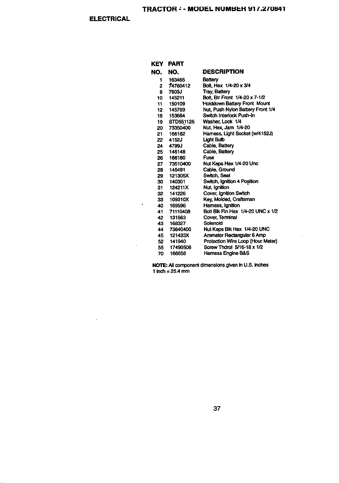
ELECTRICAL
TRACTOR ; - MODP-L NUMI::IP..H 91 _'i2-fO_l
KEY PART
NO. NO. DESCRIPTION
1 163465 Battmy
2 74760412 Bolt,Hex 114-20x3/4
8 7603J Tray, Battery
10 145211 Bolt,Btr Front 114-20x 7-I/2
11 150109 HolddownBatteryFront Mount
12 145769 Nut, PushNylon BatteryFront 1/4
16 153664 SwitchInterlockPush-In
19 STD551125 Washer, Lock 1/4
20 73350400 Nut, Hex, Jam 1/4-20
21 166182 Hamess, Ugtd Socket(w/4152J)
22 4152J LightBulb
24 4799J Cable, Battery
25 146148 Cable, Battery
26 166180 Fuse
27 73510400 Nut Keps Hex 1/4-20 Uric
28 145491 Cable, Ground
29 121305X Switch,Seat
30 140301 "Switch, Igni_on4 Po.sl_on
31 124211X Nut, Ignition
32 141226 Cover, IgnitionSwitch
33 109310X Key,Molded, Craftsman
40 169596 Harness, Ignition
41 71110408 BoltBlkFin Hex 1/4.20 UNC x 1/2
42 131563 Cover,Terminal
43 168327 Solenoid
44 73640400 NutKabsBIkHex 1/4-20UNC
45 121433X AmmeterRectangular6 Amp
52 141940 ProtectionWke Loop(Hour Meter)
55 17490508 SorewThdrol 5/16-18xl/2
70 166658 Hamess EngineB&S
NOTE: AllcomponentdimensionsgivenIn U.S. inches
1 inch =25.4 mm
37
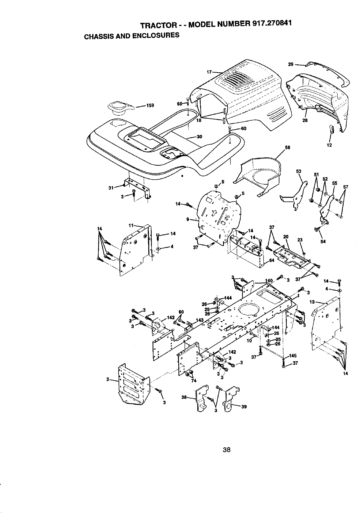
TRACTOR - - MODEL NUMBER 917.270841
CHASSIS AND ENCLOSURES
28
12
31
14 11 14
37
53
23
55
54
6O
2 74 3
14
38
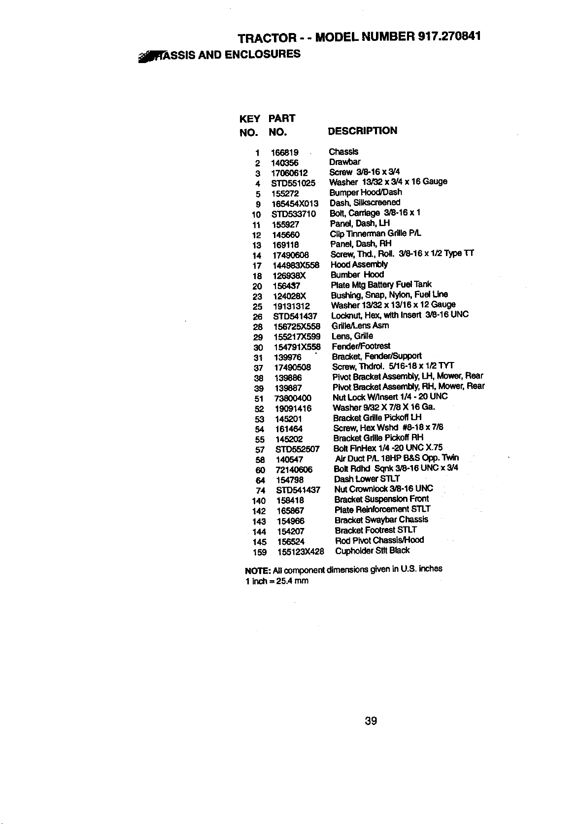
TRACTOR - - MODEL NUMBER 917.270841
_PFASSIS AND ENCLOSURES
KEY PART
NO. NO. DESCRIPTION
1 166819
2 140356
3 17060612
4 STD551025
5 155272
9 165454X013
10 STD533710
11 155927
12 145660
13 169118
14 17490608
17 144983X558
18 126938X
20 156437
23 124028)(
25 18131312
26 STD541437
28 156725X558
29 155217X599
30 154791X558
31 139976
37 17490508
38 139886
39 139887
51 73800400
52 19091416
53 145201
54 161464
55 145202
57 STD552507
58 140547
60 72140606
64 154798
74 STO541437
140 158418
142 165867
143 154966
144 154207
145 156524
159 155123X428
Chassis
Dmwbar
Screw 3/8-16 x 3/4
Washer 13/32 x3/4 x16Gauge
Bumper Hood_ash
Dash, Bllkscraened
Bolt,Carriage 3/8-16 x 1
Panel, Dash, LH
ClipTlnnermanGdlle P/t.
Panel, Dash, RH
Scraw,Thd., Roll. 3/8-16 x 1/2 Type1-1"
HoodAssembly
Bumber Hood
Plate Mtg BatteE/Fuel Tank
Bushing,Snap, Nylon,Fuel Uns
Washer 13/32 x 13/16 x 12Gauge
Locknut,He.x,with Insert 3/8-16 UNC
Grille/LensAsm
Lens, Grille
Fender/Footrest
Bracket,Feoder/Support
Scmw, Thdrol. 5/16-18x I/2 TYT
PivotBracketAssembly,LH, Mower,Rear
PluutBracketAssen_y, RH, Mower, Rear
Nut Lock W/tnsert 1/4 -20 UNC
Washer 9/32 X 7/8 X 16 Ga.
BracketGrillePickoffLH
Screw,HexWshd #8-18 x 7/8
BracketGdlle Pic_ff RH
BoltFInHex 1/4 -20 UNC )(+75
Air DuctP/L 18HP B&S Opp. Twin
BoltRdhd Sqnk3/8-16 UNC x 3/4
Dash LowerS'n_T
Nut Crownlock3/8-16 UNC
Bracket SuspensionFront
Plate RelnfomementSTLT
Bracket SwaybarChassis
Bracket FootrestSTLT
Rod PivotChassis/Hood
CupholderSlttBlack
NOTE: Allcomponentdimensionsgivenin U.S. inches
1inch ==25A mm
39
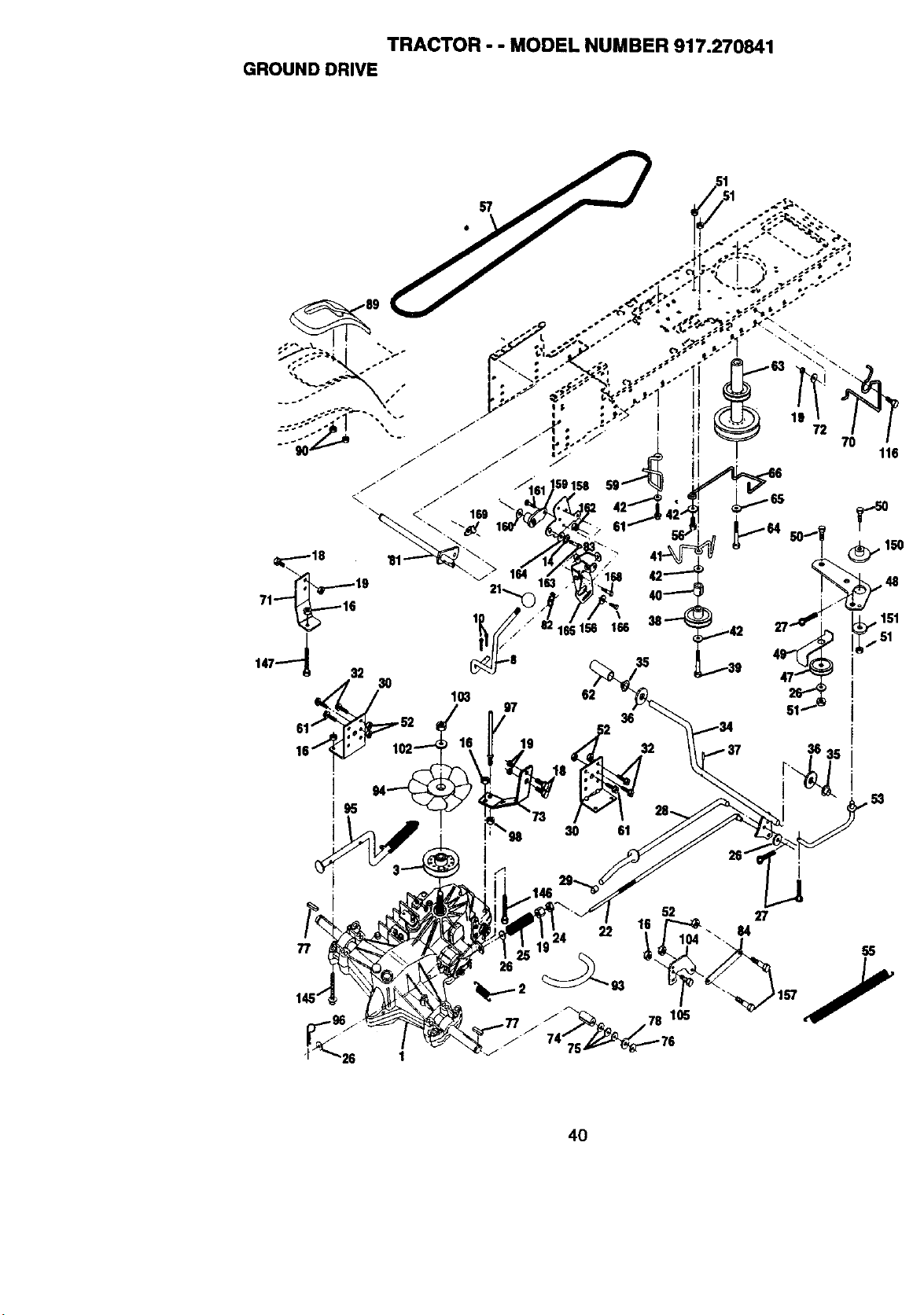
TRACTOR - - MODEL NUMBER 917.270841
GROUNDDRIVE
71-'_16
147--'_ 32
52
77
22
104
26
84
4O
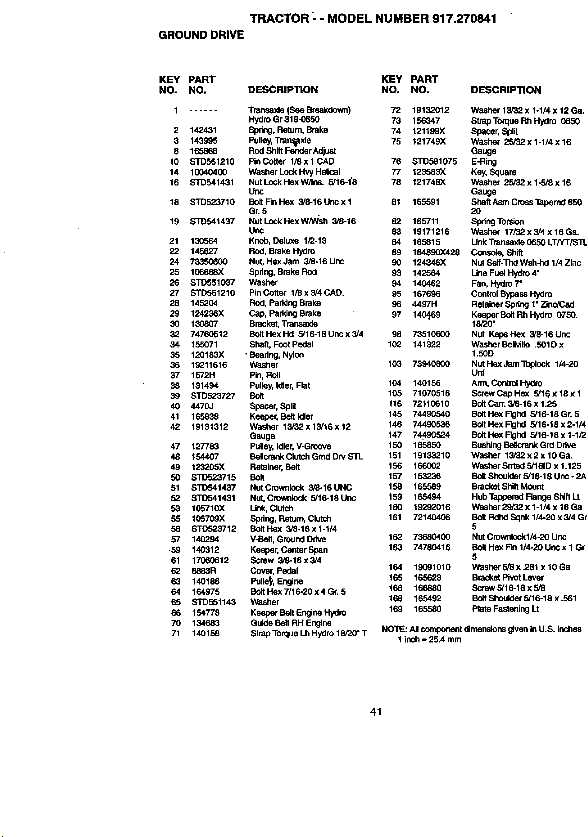
TRACTOR '- - MODEL NUMBER 917.270841
GROUND DRIVE
KEY PART KEY PART
NO. NO. DESCRIPTION NO. NO.
1 ...... Transaxla(See Breakdown) 72 19132012
HydroGr 319-0650 73 156347
2 142431 Spdng, Retum, Brake 74 121199X
3 143995 Pulley,Transpde 75 121749X
8 165866 Rod ShiftFenderAdjust
10 STD561210 PinCotter 118x 1 CAD 76 STD581075
14 10040400 Washer LockHvyHelical 77 123583X
16 STD541431 NutLockHexW/lns. 5/16-1"8 78 121748X
Uric
18 STD523710 BoltFinHex 3/6-16Uncx1 81 165591
Gr. 5
19 STD541437 NutLockHexW/W'sh 3/8-16 82 165711
Unc 83 19171216
21 130564 Knob,Deluxe 1/2-13 84 165815
22 145627 Rod,Brake Hydro 89 164890X428
24 73350600 Nut,Hex Jam 3/8-16 Unc 90 124346X
25 106888X Spring,Brake Rod 93 142564
26 STD551037 Washer 94 140462
27 STD561210 PinCotter 1/8 x 3/4 CAD. 95 167696
28 145204 Rod, ParkingBrake 96 4497H
29 124236X Cap, PaddngBrake 97 140469
30 130807 Bracket,Transaxle
32 74760512 BoltHexHd 5/16-18Uncx3/4 98 73510600
34 155071 Shaft, Foot Pedal 102 141322
35 120183X _Beadng,Nylon
36 1_11616 Washer 103 73940800
37 1572H Pin, Roll
38 131494 Pulley,Idler,Flat 104 140156
39 STD523727 Bolt 105 71070516
40 4470J Spacer, Spilt 116 72110610
41 165838 Keeper, Belt Idler 145 74490540
42 19131312 Washer 13/32 x 13/16 x 12 146 74490536
Gauge 147 74490524
47 127783 Pulley,Idler,V-Groove 150 165850
48 154407 BellcrankClutchGrnd Dry STL 151 19133210
49 123205X Retainer,Bolt 156 166002
50 STD523715 Bolt 157 153236
51 STD541437 NutCrownlock 3/8-16 UNC 158 165589
52 STD541431 Nut,Crownlock 5/16-18 Unc 159 165494
53 105710X Unk, Clutch 160 19292016
55 105709X Spring,Return,Clutch 161 72140406
56 STD523712 BeltHex 3/8-16 x 1-1/4
57 140294 V-Belt, Ground Drive 162 73680400
-59 140312 Keepar,CenterSpan 163 74780416
61 17060612 Screw 3/8-16x3/4
62 8883R Cover,Pedal 164 19091010
63 140186 Pulle_,,Engine 165 165623
64 164975 BoltHex7/16-20x4Gr. 5 166 166880
65 STD551143 Washer 168 165492
66 154778 Kasper Bolt EngineHydro 169 165580
70 134683 Guide BeltRH Engine
71 140158 StrapTorqueLhHydro 18/20"T
DESCRIPTION
Washer 13/32 x 1-1/4 x 12Ga.
StrapTorque RhHydro 0650
Spacer,Split
Washer 25/32 x 1-1/4 x 16
Gauge
E-Fling
Key,Square
Washer 25/32 x 1-5/8 x 16
Gauge
ShaftAsm CrossTapered 650
2O
SpringTorsion
Washer 17/32 x 3/4 x 16 Ga.
LinkTransa,_de0650 LTHT/STL
Console,Shift
Nut Self:hid Wsh-hd 1/4 Zinc
LineFuel Hydro4"
Fan, I-lydro7"
ControlBypassHydro
Retainer Spring1"Zinc/Cad
Kasper Bo_Rh Hydro 0750.
18/20'
Nut KepaHex 3/6-16Unc
Washer Bellville .501D x
1.50D
Nut HexJam Toplook 1/4-20
Unf
Arm, Control Hydro
ScrewCap Hex 5/16 x 16 x I
BoltCan'.3/6-16 x 1.25
BoltHex Flghd 5/16-18 Gr. 5
BoltHex Flghd 5/16-18 x 2-1/4
BoltHex Flghd 5/16-18 x 1-1/2
BushingBollcrank Grd Ddve
Washer 13/32 x2 x 10 Ga.
Washer Srrted5/161Dx 1.125
BoltShoulder5/16-18 Unc - 2A
BracketShiftMount
HubTapperedFlange ShiftI_t
Washer 29/32 x 1-1/4 x 16 Ga
BoltRdhdSqnk 114-20x3/4 Gr
5
Nut Crownlockl/4-20 Unc
BoltHex Fin 114-20Uric x I Gr
5
Washer 5/8 x .281 x 10 Ga
BracketPivotLever
Scraw 5/16-18 x 5/8
BoltShoulder5/16-18 x .561
Plate FasteningLt
NOTE: Allcomponentdlrnensions giveninU.S. inches
1inch= 25.4 mm
41
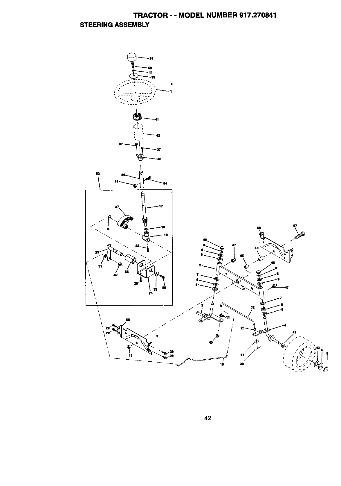
TRACTOR - - MODEL NUMBER 917.270841
STEERING ASSEMBLY
• • L • _i
_41
t" -i
n
I
_ 114
47
1$
42
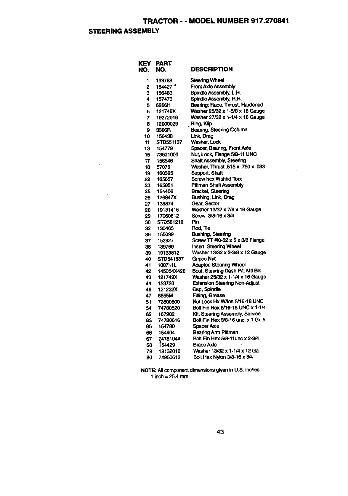
TRACTOR - - MODEL NUMBER 917.270841
STEERING ASSEMBLY
KEY PART
NO. NO. DESCRIPTION
1 139768
2 154427"
3 156483
4 157473
5 6266H
6 121748X
7 19272016
8 12000029
9 3366R
10 156438
11 STD551137
13 154779
15 73901000
17 156546
18 57079
19 160395
22 165857
23 165851
25 154406
26 126847X
27 136874
28 19131416
29 17O6O612
30 STD561210
32 13O465
36 155099
37 152927
38 139769
39 19133812
40 STD541537
41 100711L
42 145054X428
4,3 121749X
44 153720
46 121232X
47 6855M
51 738OO50O
54 74780520
62 167902
63 74780616
65 154780
66 154404
67 74781044
68 "[54429
79 19132012
80 74950612
SteeringWheel
FrontAxleAssembly
SpindleAssembly,LH.
Splnd_ Aseem_, R.H.
Bearing;,Race,Thrust, Hardened
Washer 25/32 x 1-5/8 x 16 Gauge
Washer 27/'32x 1-1/4 x 16 Gauge
Ring, Klip
Bearing, SteedngColumn
Unk, Drag
Washer, Lock
Spacer, Bearing,FrontAxle
Nut, Lock,Range 5/8-11 UNC
ShaftAssembly,Steedng
Washer,Thrust ,515 x .750 x .033
Suppor_she_
Screwhex Wshhd Torx
Pittman ShaftAssembly
Bracket,Steering
Busl'_ng,Unk, Drag
Gear, Sector
Washer 13F32x7/8 x 16 Gauge
Screw 3/6-16 x3/4
Pin
Rod, "Re
Bushing,Steedng
Screw"[-r#10-32x 5 x 3/8 Range
Insert,Steedng Wheel
Washer 13/32 x 2-3/8 x 12 Gauge
GripcoNut
Adaptor,SteeringWheel
Boot,SteeringDash P/L MtlBIk
Washer25/32 x 1-1/4 x 16Gauge
ExtensionSteedngNon-Adjust
pap,sp_d_
F_ng, Grease
Nut LockHx W/ins 5/16-19 UNC
BoltFin Hex 5/16-18 UNC x 1-1/4
Wit,SteeringAssembly,Sen/ice
BoltFinHex 3/8-16 unc. x 1 Gr.5
SpacerAxle
BeadngArm Pittman
BoltFinHex 5/8-1lunc x 2-3/4
Brace Axle
Washer 13/32 x 1-1/4 x 12 Ga
BoltHex Nylon3/8-16 x 3/4
NOTE: Allcomponentdimensionsgivenin U.S. inches
1 inch= 25.4 mm
43
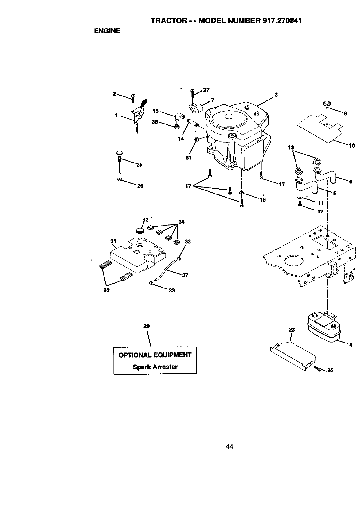
SttG\_
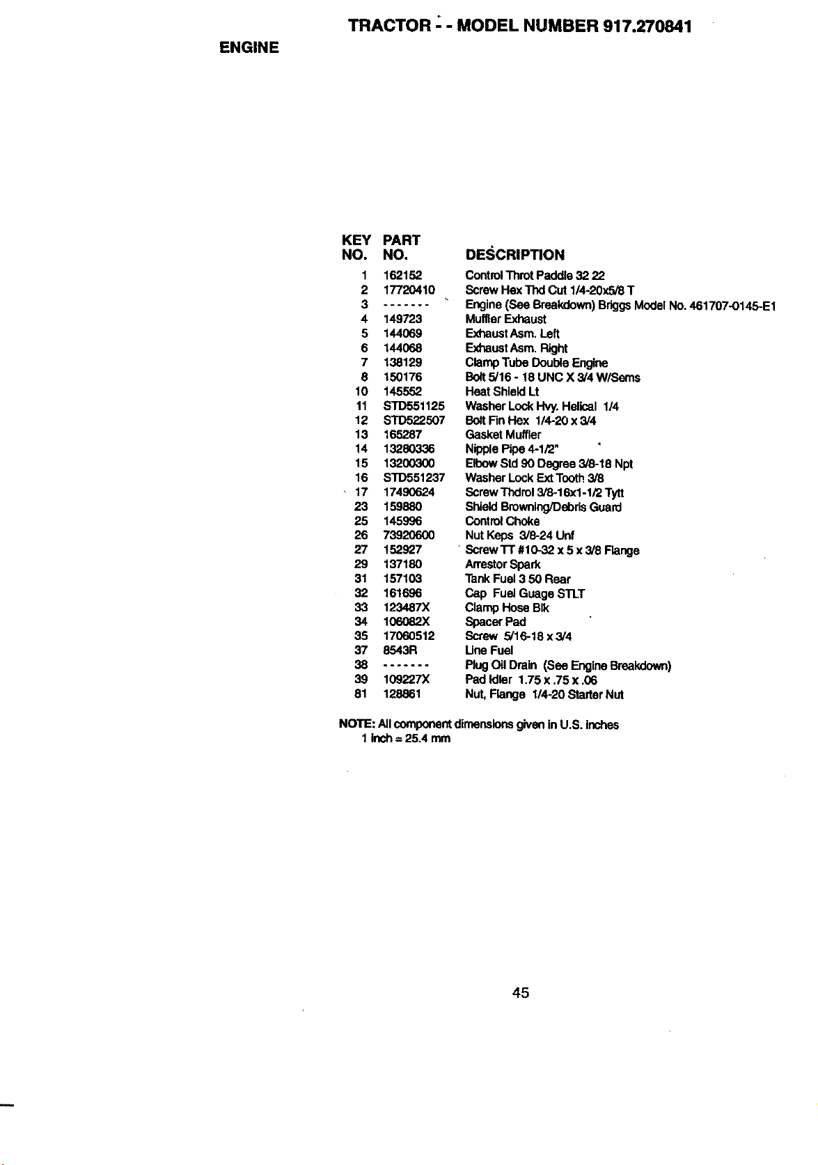
ENGINE
TRACTOR _- MODEL NUMBER 917.270841
KEY PART
NO. NO.
1 162152
2 17720410
3 .......
4 149723
5 144069
6 144068
7 138129
8 150176
10 145552
11 STD551125
12 STD522507
13 165287
14 13280336
15 13200300
16 STD551237
17 17490624
23 159880
25 145996
26 73920600
27 152927
29 137180
31 157103
32 161696
33 123487)(
34 106082X
35 17060512
37 8543R
38 .......
39 109227X
81 128861
DESCRIPTION
ControlThrot Paddle 32 22
Screw HexThd Cut 1/4-20x5/8 T
Engine(See Breakdown)BrkjgsModelNo. 461707-0145-E1
MufflerExhaust
ExhaustAsm. Left
ExhaustAsm. Right
ClampTube Double Engine
Bolt5/16 - 18 UNC X 3/4 W/Seres
Heat Shield Lt
Washer LockHvy.Helical 1/4
BoltFin Hex 1/4-20 x 3/4
Gasket Muffler
NipplePipe 4-1/2"
EFbowStd 90 Degree 5/8-18 Npt
Washer LockExt Tooth3/8
ScrewThdrol3/8-16xl -1/2 Tytt
Shield Browning/DebrisGuard
Control Choke
Nut Keps 3/8-24 Unf
"Screw'l-r #10-32 x 5 x3/8 Flange
ArrestorSpark
TankFuel3 50 Rear
Cap Fuel Guage STLT
Clamp Hose BIk
Spacer Fad
Screw 5/16-18 x 3/4
LineFuel
Plug Oil Drain (See EngineBreakdown)
Pad Idler 1.75 x .75 x .06
Nut, Flange 1/4-20 StarterNut
NOTE: Allcomponentdimensionsgivenin U.S. inches
1 inch =25A mm
45
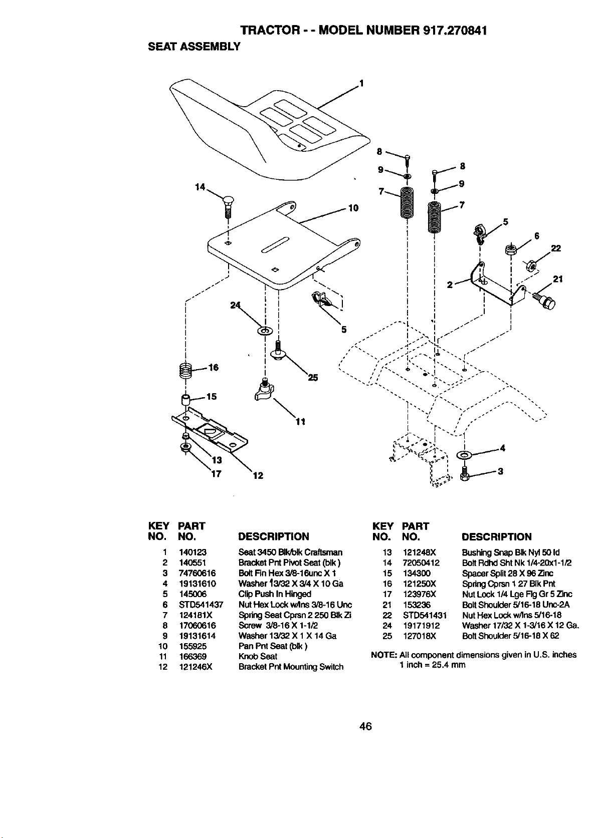
TRACTOR - - MODEL NUMBER 917.270841
SEAT ASSEMBLY
I
5
21
KEY PART
NO. NO.
1 140123
2 140551
3 74760616
4 19131610
5 145006
6 STD541437
7 124181X
8 17060616
9 19131614
10 155925
11 166369
12 121246X
KEY PART
DESCRIPTION NO. NO. DESCRIPTION
Seat 3450 BllVolkCraftsman 13 121248X
Bracket PntPivot Seat (blk) 14 72050412
Bo4tFinHex 3/8-16unc X 1 15 134300
Washer _3/32 X 3/4 X I0 Ga 16 121250X
Clip Push In Hinged 17 123976X
Nut Hex Lockw/Ins 3/8-16 Unc 21 153236
SpringSeat Cpran2250 BIkZi 22 STD541431
Screw 3/8-16X 1-1/2 24 19171912
Washer13/32X1 X14Ga 25 127018X
Pan PntSeat (blk)
KnobSeat
BracketPntMountingSwitch
BushingSnap BIkNy150Id
BoltRdhdSht Nk 1/4-20xl-1/2
SpacerSplit28 X 96 Zinc
SpringCprsn I 27 BIkPnt
Nut Lock1/4 LgeFigGr 5 Zinc
BoltShoulder5/16-18 Unc-2A
Nut Hex Lockw/lns3/16-18
Washer 17/32.X 1-3/16X 12 Ga.
BoltShoulder5/16-18 X 62
NOTE: All component dimensionsgiven in U.S. inches
1 inch = 25.4 mm
46
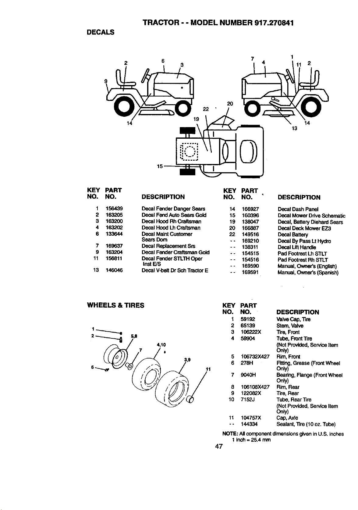
DECALS
TRACTOR - - MODEL NUMBER 917.270841
2
3
7
4
1
11 2
9
KEY
NO.
I
2
3
4
6
PART
NO.
156439
1632OO
163202
133644
7 169637
9 1632O4
11 156811
13 146046
14
15
2O
DESCRIPTION
KEY PART
NO. NO.
Decal Fender Danger Seam
Deeal Fend Auto SearsGold
Decal Hood RhCraftsman
Decal Hood LhCraftsman
Decal Maint Customer
Seats Dora
Decal Replacement Srs
Decal Fender CraftsmanGold
Decal Fender STL11-IOper
InstF_JS
Decal V-belt Dr SchTractor E
14 166927
15 160396
19 138047
20 166887
22 149516
- - 169210
- - 138311
- - 154515
- - 154516
- - 169590
-- 169591
14
13
DESCRIPTION
Decal Dash Panel
Decal Mower DriveSchematic
Decal, BatteryDiehardSears
Decal Deck Mower EZ3
Decal Battery
Decal By Pass Lt Hydro
Decal LiftHandle
Pad FootrestLh STLT
Pad FootrestRh STLT
Manual,Owner's (English)
Manual,Owner's (Spanish)
WHEELS & TIRES
11
KEY PART
NO. NO. DESCRIPTION
1 59192 Valve Cap, Tire
2 65139 Stem,Valve
3 106222X Tire, Front
4 59904 Tube, Front'nre
(Not Provided, Service Item
Only)
5 "f06732X427 Rim, Front
6 278H Rtting, Grease (Front Wheel
Only)
7 9040H Baanng, Flange (FrontWheel
Only)
8 106108X427 Rim, Rear
9 122082X Tire, Rear
10 7152J Tube, RearTire
(Not Provided.ServiceItem
Only)
11 104757X Cap, Axle
- - 144334 Sealant,"fire(10 oz. Tube)
NOTE: All componentdimensionsgiven inU.S. inches
1 inch= 25.4 mm
47
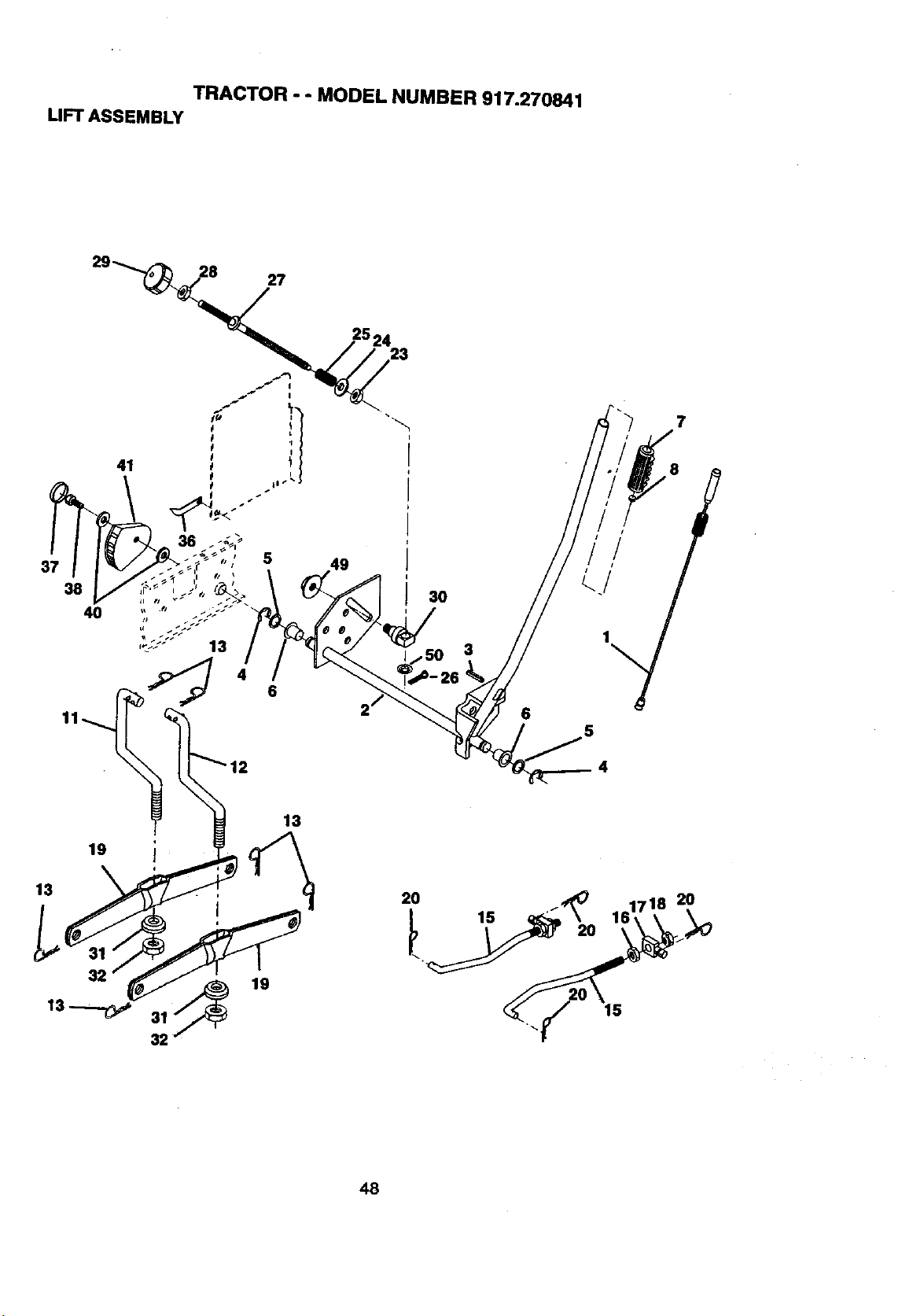
TRACTOR - - MODEL NUMBER 917.270841
LIFT ASSEMBLY
37 5 49
30
3
6
7
4
48
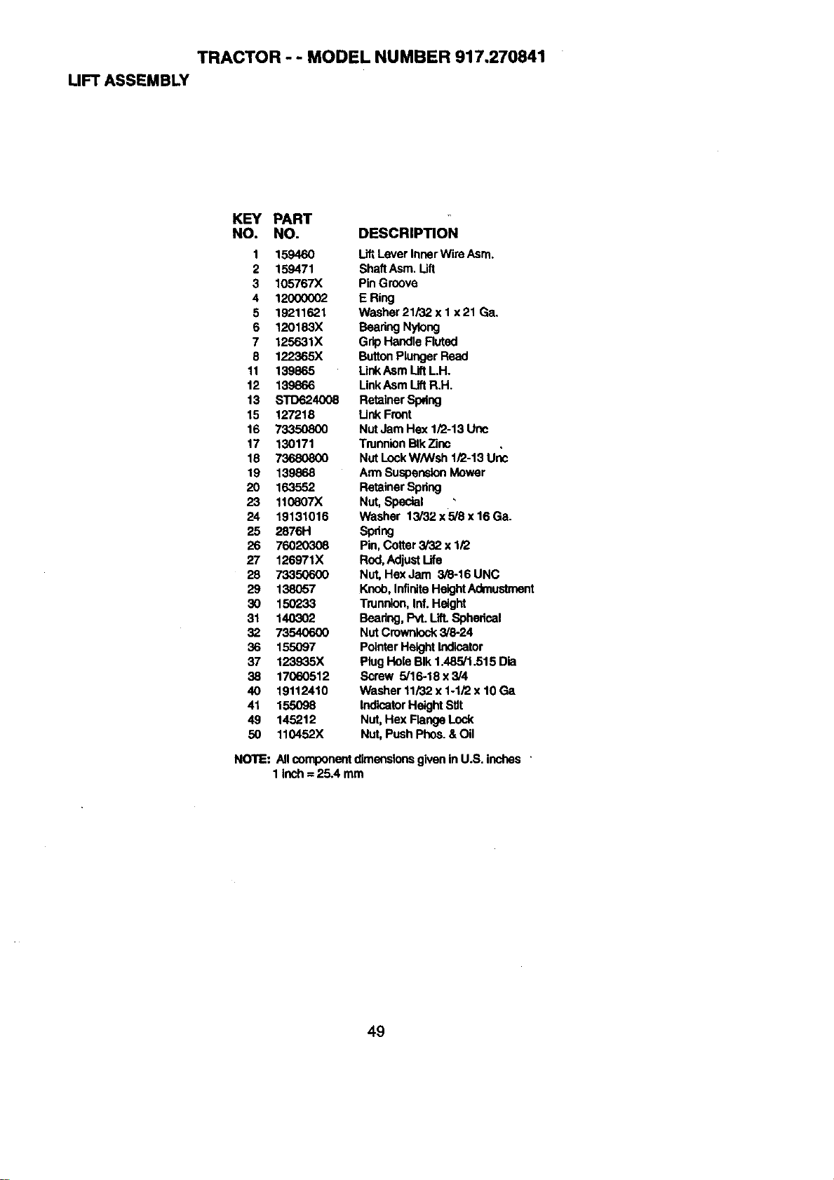
TRACTOR - - MODEL NUMBER 917,270841
LIFT ASSEMBLY
KEY PART
NO. NO. DESCRIPTION
1 159460 LiftLever InnerWire Asrn.
2 159471 ShaftAsm. Uft
3 105767X Pin Groove
4 120000(_ E Ring
5 19211621 Washer21/32x1 x21 Ga,
6 120183X Beadng Nylong
7 125631X Grip Handle Ruted
8 122365X ButtonPlungerRead
11 139865 LinkAsm LiftLH.
12 139866 LinkAsm LiftR.H.
13 STD624008 Retainer Spring
15 127218 Link Front
16 73350800 Nut Jam Hex 1/2-13 Unc
17 130171 TrunnionBlkZinc
18 73680800 NutLockW/Wsh I/2-I 3 Uric
19 139868 Arm SuspensionMower
20 163552 Retainer Spring
23 110807X Nut,Special , "
24 19131016 Washer 13/32x5/8x16Ga.
25 2876H Spdng
26 76020308 Pin,Cotter 3/32 x 1/2
27 126971X Rod,AdjustLife
28 73350600 Nut,Hex Jam 3/8-16 UNC
29 138057 Knob,InfiniteHeightAdmustment
30 150233 Trunnion,Inf.Height
31 140302 Beadng,PvL Lift.Sphedcal
32 73540600 NutCrowniock3/8-24
36 155097 PointerHeight Indicator
37 123935X Plug Hole BIk 1A85/1.515 Die
38 17060512 Screw 5/16-18x3/4
40 19112410 Washer 11/32x 1-1/2 x 10 Ge
41 155098 IndicatorHeight Stir
49 145212 Nut, Hex Flange Lock
50 110452X Nut,Push Phos.& Oil
NOTE: All componentdimensionsgivenin U.S. inches
1Inch = 25A mm
49
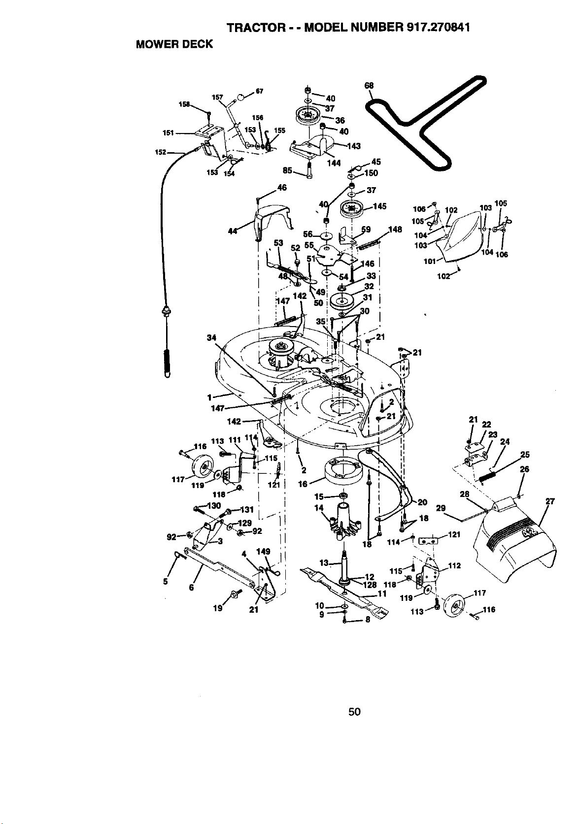
TRACTOR - - MODEL NUMBER 917.270841
MOWER DECK
lS7 _C_,"_ _._ 40 _ _aF"._P'_
lo,___T__ ",_
1_2____ _1. _
,._1_ .._ 144_,_
6
\
16
21 22
324
1
13_
26
27
SO
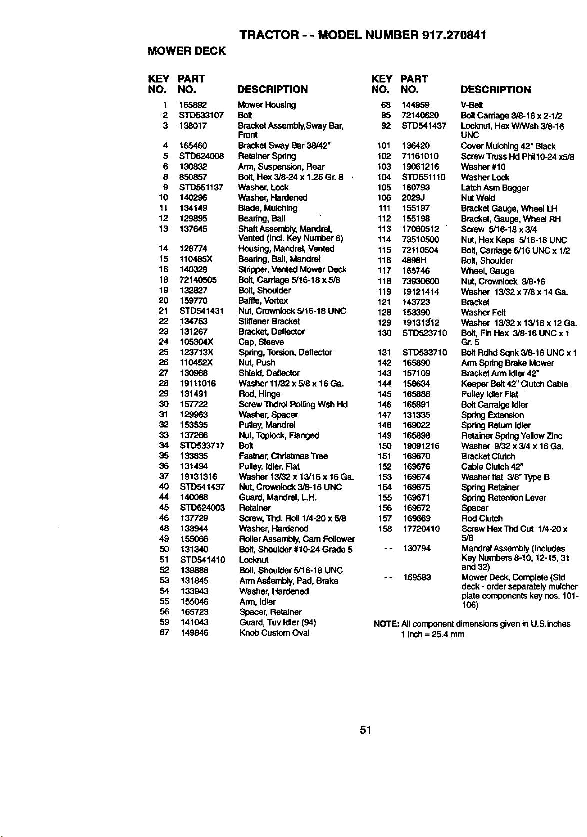
TRACTOR - - MODEL NUMBER 917.270841
MOWER DECK
KEY PART KEY PART
NO. NO. DESCRIPTION NO. NO.
1 165852 Mower Housing 68 144959
2 STD533107 Bolt 85 72140620
3 138017 BracketAssembly,SwayBar, 92 STD541437
Front
4 165460 BracketSway Bar 38/42" 101 136420
5 STD624008 RetainerSpdng 102 71161010
6 130832 Arm, Suspension,Rear 103 19061216
8 850857 Beft,Hex3i8-24x1.25Gr.8 • 104 STD551110
9 STD551137 Washer, Lock 105 160793
10 140296 Washer, Hardened 106 2029J
11 134149 Blade, Mulching 111 155197
12 129895 Beadng,Ball 112 155198
13 137645 ShaftAseambly, Mandrel, 113 17060512 "
Vented (Incl.Key Number6) 114 73510500
14 128774 Housing,Mandrel, Vented 115 72110504
15 110485X Beadng, Ball,Mandrel 116 4898H
16 140329 Stripper,Vented Mower Deck 117 165746
18 72140505 BoIt,Cardage5/16-18x5/8 118 73930600
!9 132827 Boll Shoulder 119 19121414
20 159770 Baffle,Vortex 121 143723
21 STD541431 Nut,Crowniock5/16-18 UNC 128 153390
22 134753 StiffenerBracket 129 191313'12
23 131267 Bracket,Deflector 130 STD523710
24 105304X Cap, Sleeve
25 123713X Spdng,Torsion,Deflector 131 STD533710
26 110452X Nut, Push 142 165890
27 130968 Shield,Deflector 143 157109
28 19111016 Washerlli32xs/8x16Ga. 144 158634
29 131491 Rod, Hinge 145 165888
30 157722 ScrewThdrolRollingWsh lid 146 165891
31 129963 Washer,Spacer 147 131335
32 153535 Pulley,Mandrel 148 169022
33 137266 Nut,Topiock,Flanged 149 165898
34 STD533717 Bolt 150 19091216
35 133835 Fastner,ChristmasTree 151 169670
36 131494 Pulley,Idler,Flat 152 169676
37 19131316 Washer t3/32x 13/16x 16Ga. 153 169674
40 STD541437 Nut,Crownlock3/8-16 UNC 154 169675
44 140088 Guard, Mandrel, LH. 155 169671
45 STD624003 Retainer 156 169672
46 137729 Screw,Thd. Roll 1/4-20 x 5/8 157 16O669
48 133944 Washer, Hardened 158 17720410
49 155066 RollerAssembly,Cam Follower
50 131340 Bolt, Shoulder#10-24 Grade 5 - - 130794
51 STD541410 Locknut
52 139888 Bolt,Shoulder5/16-18 UNC
53 131845 Arm AsSembly,Pad, Brake - - 169583
54 133943 Washer, Hardened
55 155046 Arm, Idler
56 165723 Spacer,Retainer
59 141043 Guard,Tuv Idler (94)
67 149846 KnobCustomOval
DESCRIPTION
V-Belt
BoltCarriage 3/8-16 x2-1/2
Locknut,HexW/Wsh 3/8-16
UNC
Cover Mulching42" Black
ScrewTrussHd PhUl0-24 x5/8
Washer #10
Washer Lock
LatchAsmBagger
Nut Weld
Bracket Gauge, Wheel LH
Bracket,Gauge, Wheel RH
Screw 5/16-18 x 3/4
Nut, Hex Kepe 5/16-18 UNC
Bolt, Carriage 5/16 UNC x 1/2
Bolt, Shoulder
Wheel, Gauge
Nut, Crownlock 3_-16
Washer 13/32 x7/8 x 14 Ga.
Bracket
Washer Felt
Washer 13/32 x 13/16 x 12Ga.
Bolt,Fin Hex 3/8-16 UNC x 1
Gr.5
BoltRdhdSqnk3/8-16 UNC x 1
Ann SpdngBrake Mower
BracketArm Idler42"
Keeper Belt42"ClutchCable
PulleyIdlerFlat
BoltCarraigeIdler
Spdng Extension
Spdng Retum Idler
RetainerSpdngYellowZinc
Washer 9/'32x 3/4 x 16Ga.
Bracket Clutch
Cable Clutch42"
Washer flat 3/8" Type B
Spdng Retainer
SpdngRetentionLever
Spacer
RodClutch
ScrewHex ThdCut 1/4.20 x
5/8
MandrelAssembly(includes
Key Numbers8-10, 12-15, 31
and 32)
Mower Deck, Complete(Std
deck - orderseparatelymulcher
platecomponentskeynos. 101-
106)
NOTE: All componentdimensionsgivenin U.S.inches
1 inch= 25.4 mm
51
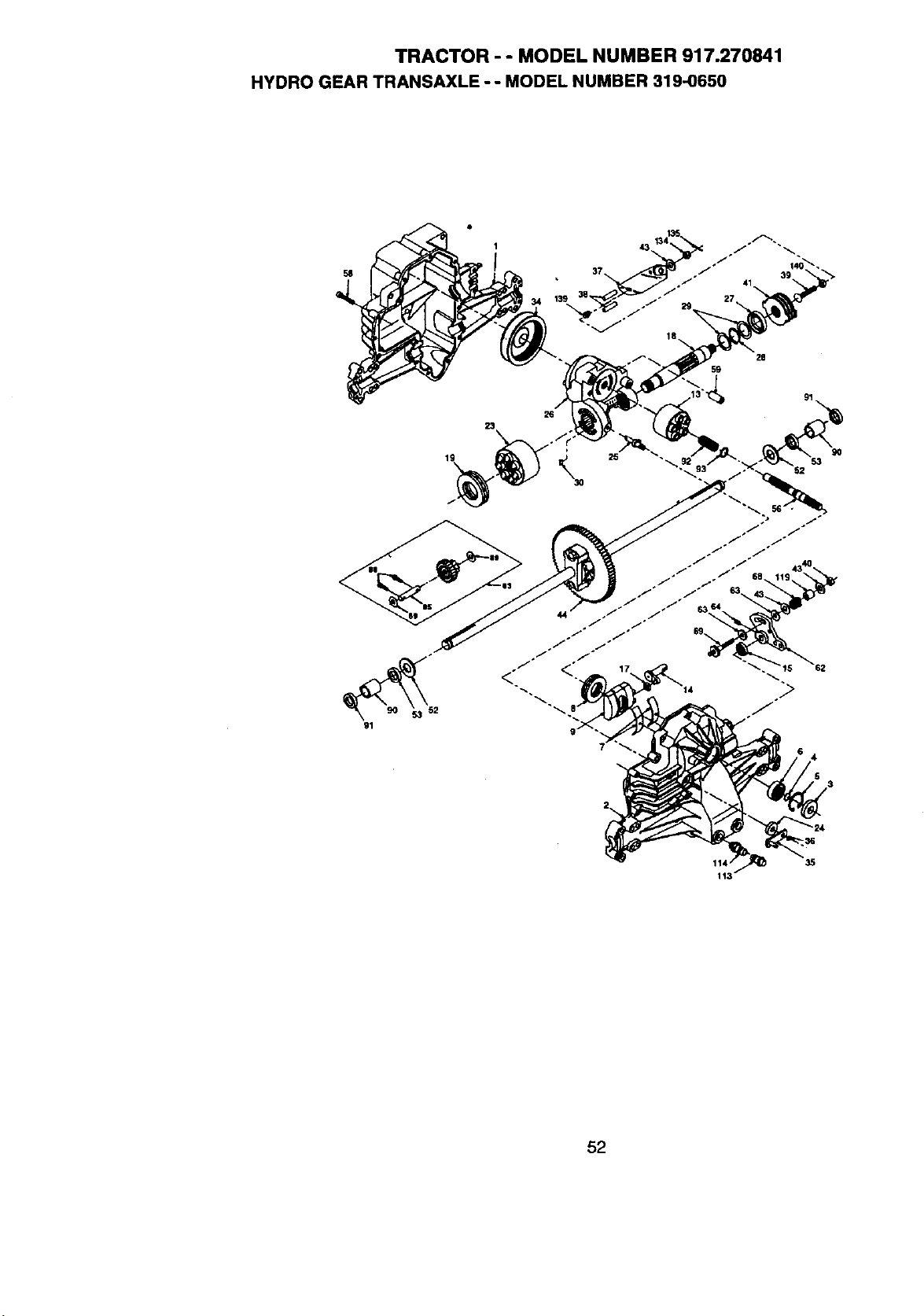
TRACTOR - - MODEL NUMBER 917.270841
HYDRO GEAR TRANSAXLE - - MODEL NUMBER 319-0650
91
23
19
i_ 25 53
9O
111 35
113
52
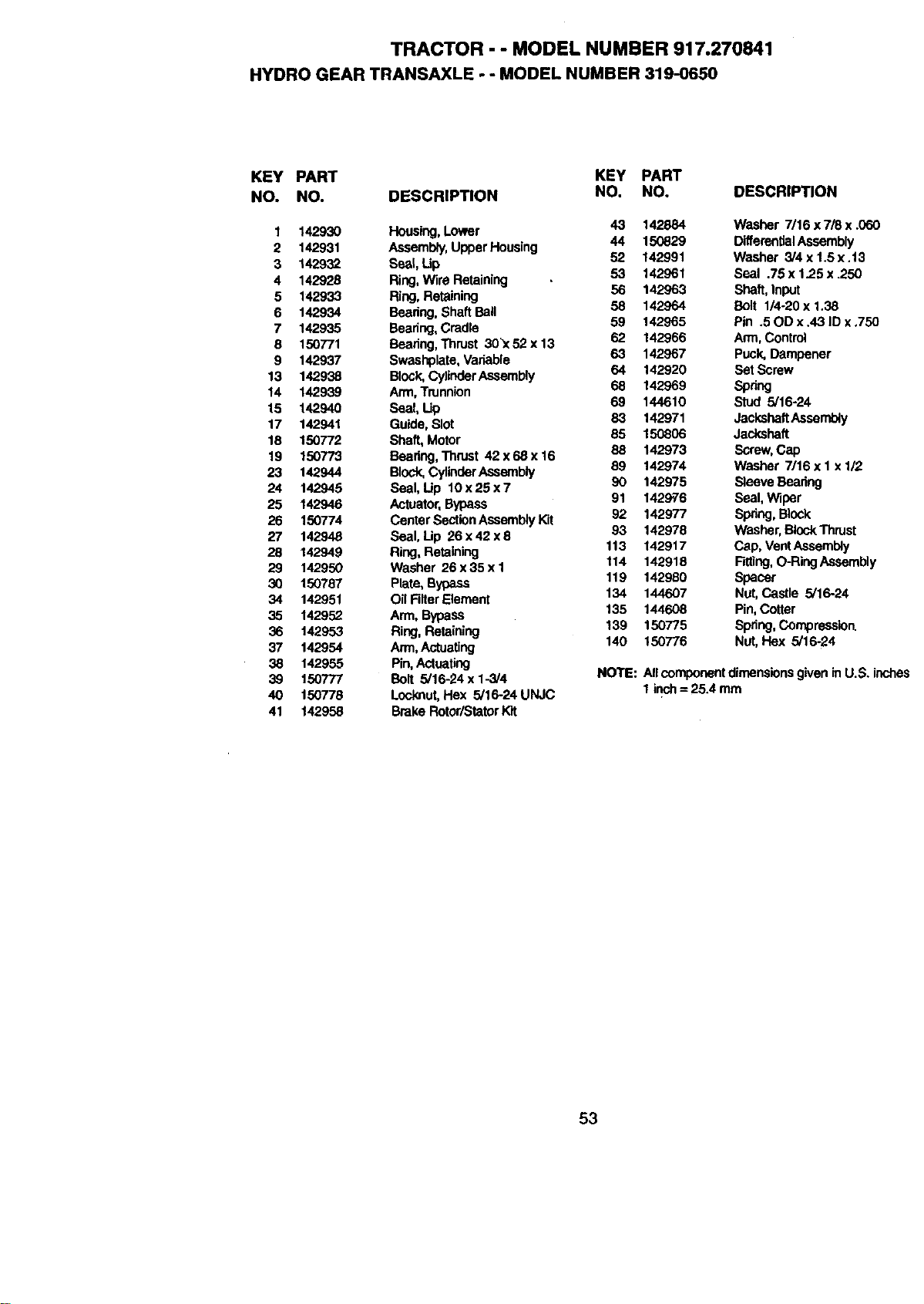
TRACTOR - - MODEL NUMBER 917.270841
HYDRO GEAR TRANSAXLE - - MODEL NUMBER 319-0650
KEY PART KEY PART
NO. NO. DESCRIPTION NO. NO.
1 142930 Housing, Lower 43 142884
2 142931 Assembly,UpperHousing 44 150829
3 142932 Seal, Lip 52 142991
4 142926 Ring,Wire Retaining 53 142961
5 142933 Ring, Retaining 56 142963
6 142934 Beadng, Shaft Ball 58 142964
7 142935 Beadng,Cradle 59 142965
8 150771 Beadng,Thrust 30_<52 x 13 62 142966
9 142937 Sweshplate, Variable 63 142967
13 142938 Block,CylinderAssembly 64 142920
14 142939 Arm, Trunnion 68 142969
15 142940 Seal, Lip 69 144610
17 142941 Guide, Slot 83 142971
18 150772 Shaft, Motor 85 150806
19 150773 Beadng,Thrust 42x68x16 88 142973
23 142944 Block,CylinderAssembly 89 142974
24 142945 Seal, Up 10 x 25 x 7 90 142975
25 142946 Actuator,Bypass 91 1429'76
26 150774 Canter SectionAssemblyKit 92 142977
27 142948 Seal, Lip 26 x 42 x 8 93 142978
28 142949 Ring, Retaining 113 142917
29 142950 Washer 26x35x1 114 142918
30 150767 Plate, Bypass 119 142980
34 142951 Oil Rlter Element 134 144607
35 142952 Ann, Bypass 135 144608
36 142953 Ring, Retaining 139 150775
37 142954 Arm,Actuating 140 150776
38 142955 Pin,Actuating
39 150777 Bolt 5/16-24xl-5/4
40 150778 Lock,nut,Hex 5/16-24 UNJC
41 142958 Brake Rotor/StatorKit
DESCRIPTION
Washer 7/16 x 7/8 x .060
DifferentialAssembly
Washer 3/4 x 1.5 x.13
Seal .75 x 1.25 x .250
Shaft, Input
Bolt 1/4-20 x 1.38
Pin .50D x .43 ID x ,750
Arm, Control
Puck, Dampener
Set Screw
spring
Stud 5/16-24
JackshaftAssembly
Jackshaft
Screw, Cap
Washer 7/16 x 1 x 1/2
Sleeve Bearing
Seal, Wiper
sp_ng,Biock
Washer, BlockThrust
Cap, VentAssembly
F_ng, O-RingAssembly
Spacer
Nut,Castle 5/16-24
Pin,Cotter
Spring,Compression.
Nut,Hex 5/16-24
NOTE: Allcomponentdimensionsgiven in U.S. inches
1inch = 25.4 mm
53
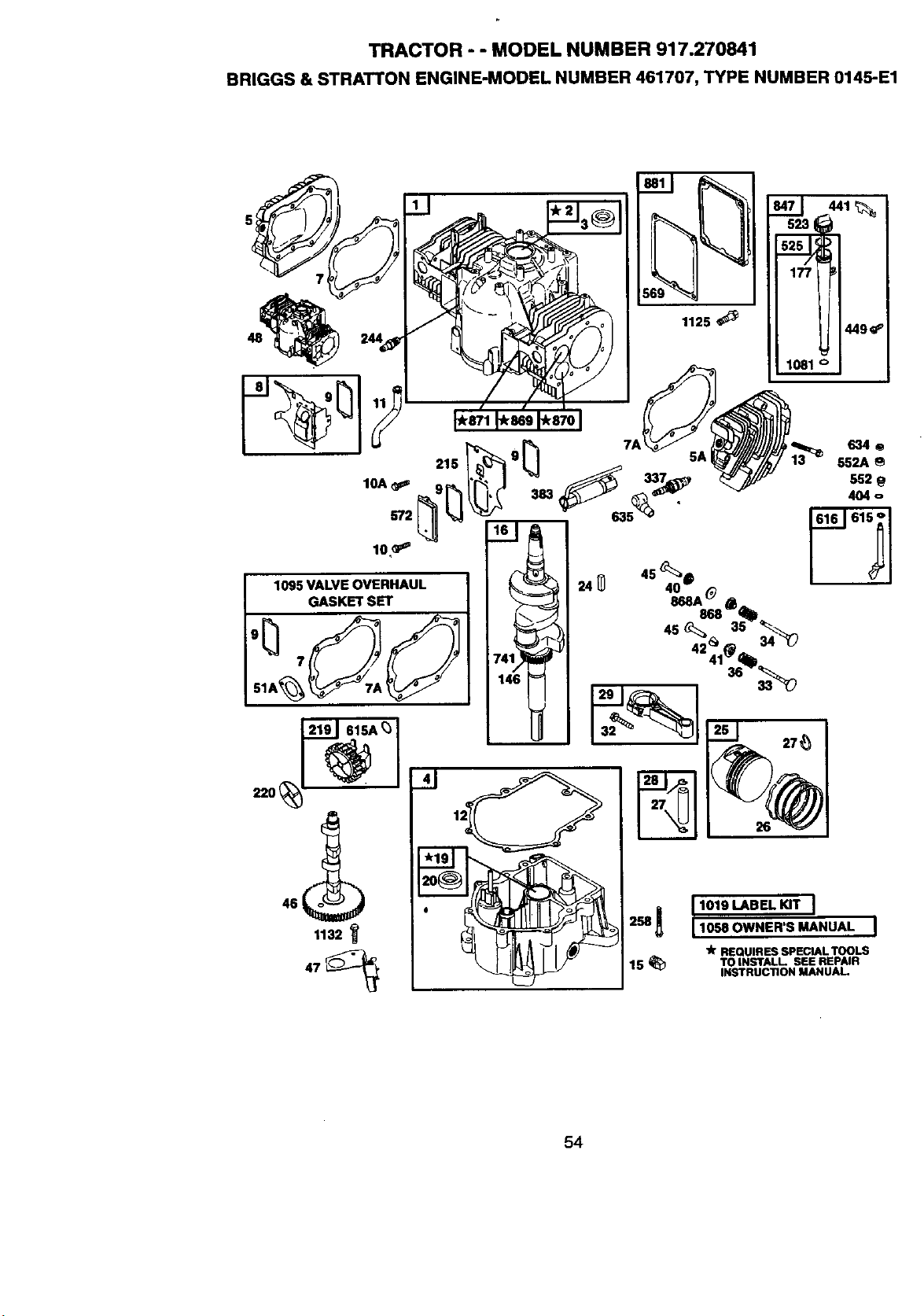
TRACTOR - - MODEL NUMBER 917.270841
BRIGGS & STRATTON ENGINE-MODEL NUMBER 461707, TYPE NUMBER 0145-E1
215
10A
572
10GP_
1095 VALVE OVERHAUL
GASKET SET
1132
383
634o
552A
552
404 o
2._ I101SL_BELKrrI
IlO-OWHER'S_.UAL
'k REQUIRES SPECIAL TOOLS
15 _ TO INSTALL SEE REPAIR
INSTRUCTION MANUA 1
54
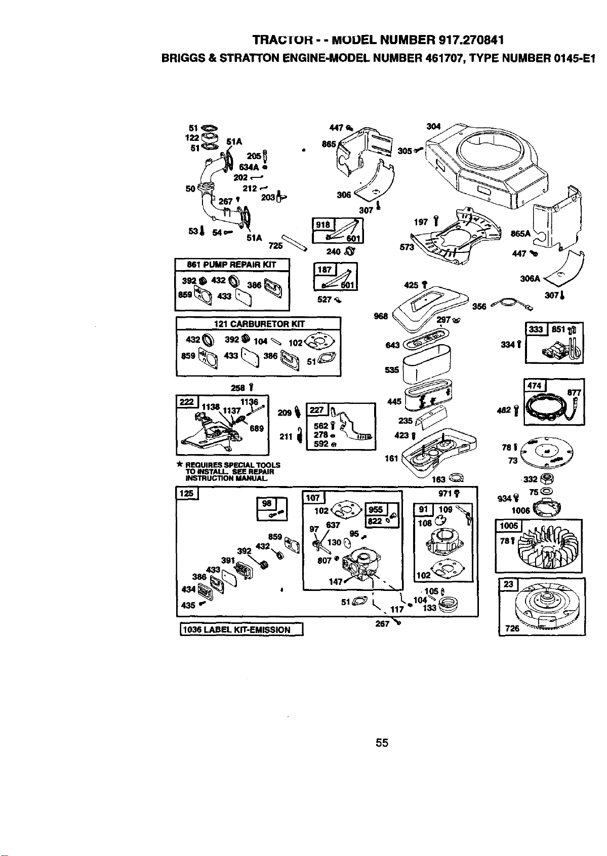
TRAC;TOH - - MuUEL NUMBER 917.270841
BRIGGS & STRATI"ON ENGINE-MODEL NUMBER 461707, TYPE NUMBER 0145-E1
307
8615,,,..6.'A725_
861 PUMP REPAIR KIT I
12.,CAR.U,E'rORKIT I
68_ _ _68_ 51_ I
286V
i
] nl 562_ _I |
689 211 dl 276. Xa._, I
"1 s.2_ I
Ik REQUIRES SPECIAL TOOLS
TO INSTALl. SEE REPAIR
INSTRUCTION MANUAL.
968
643
535
1036 LABEL KIT-EMISSION I
G5
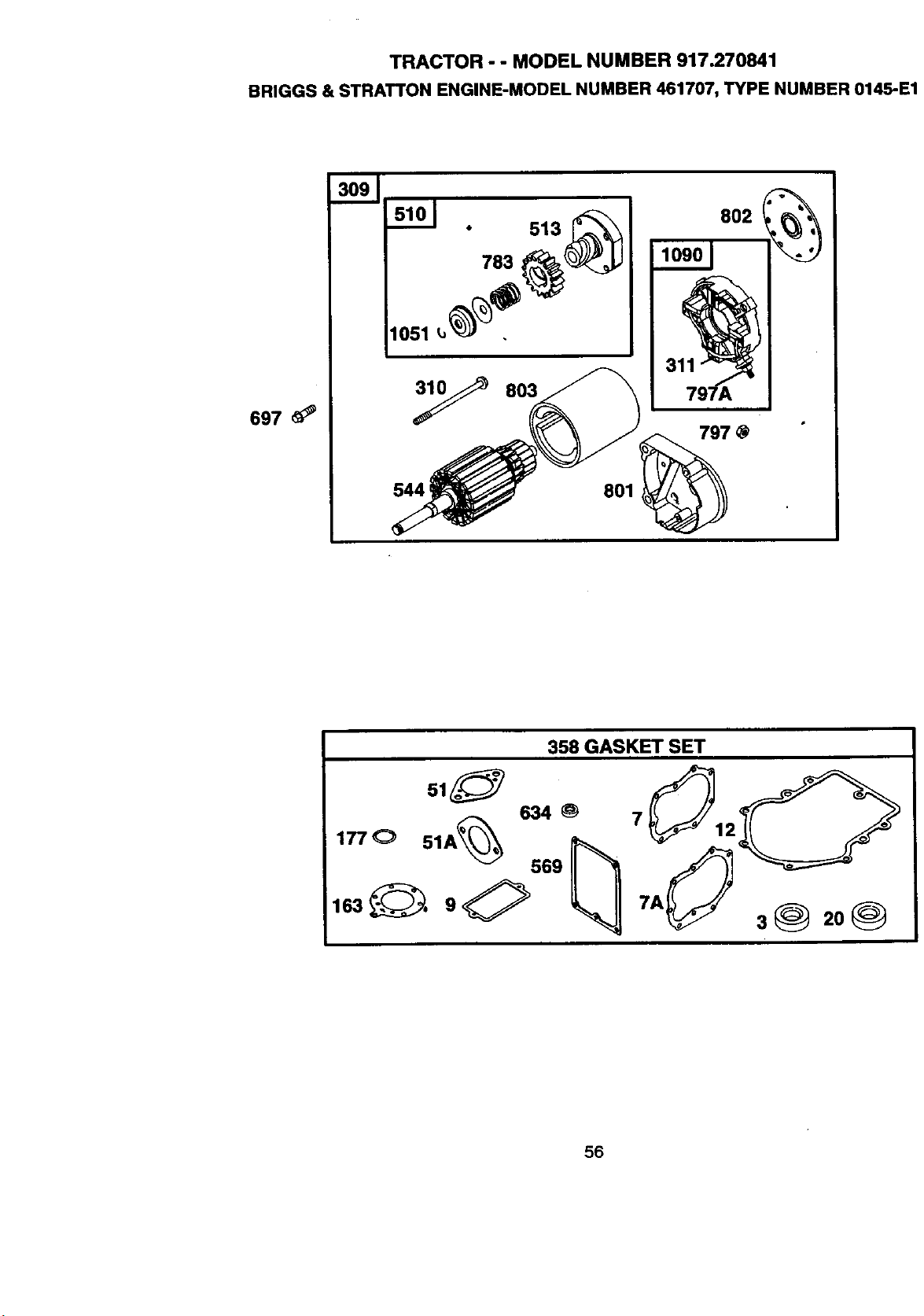
TRACTOR - - MODEL NUMBER 917.270841
BRIGGS & STRATTON ENGINE-MODEL NUMBER 461707, TYPE NUMBER 0145-E1
697
513
783
y 803
544 i
801
797 @
358 GASKET SET
634_ 7
1770 51A _'_ 569_
56
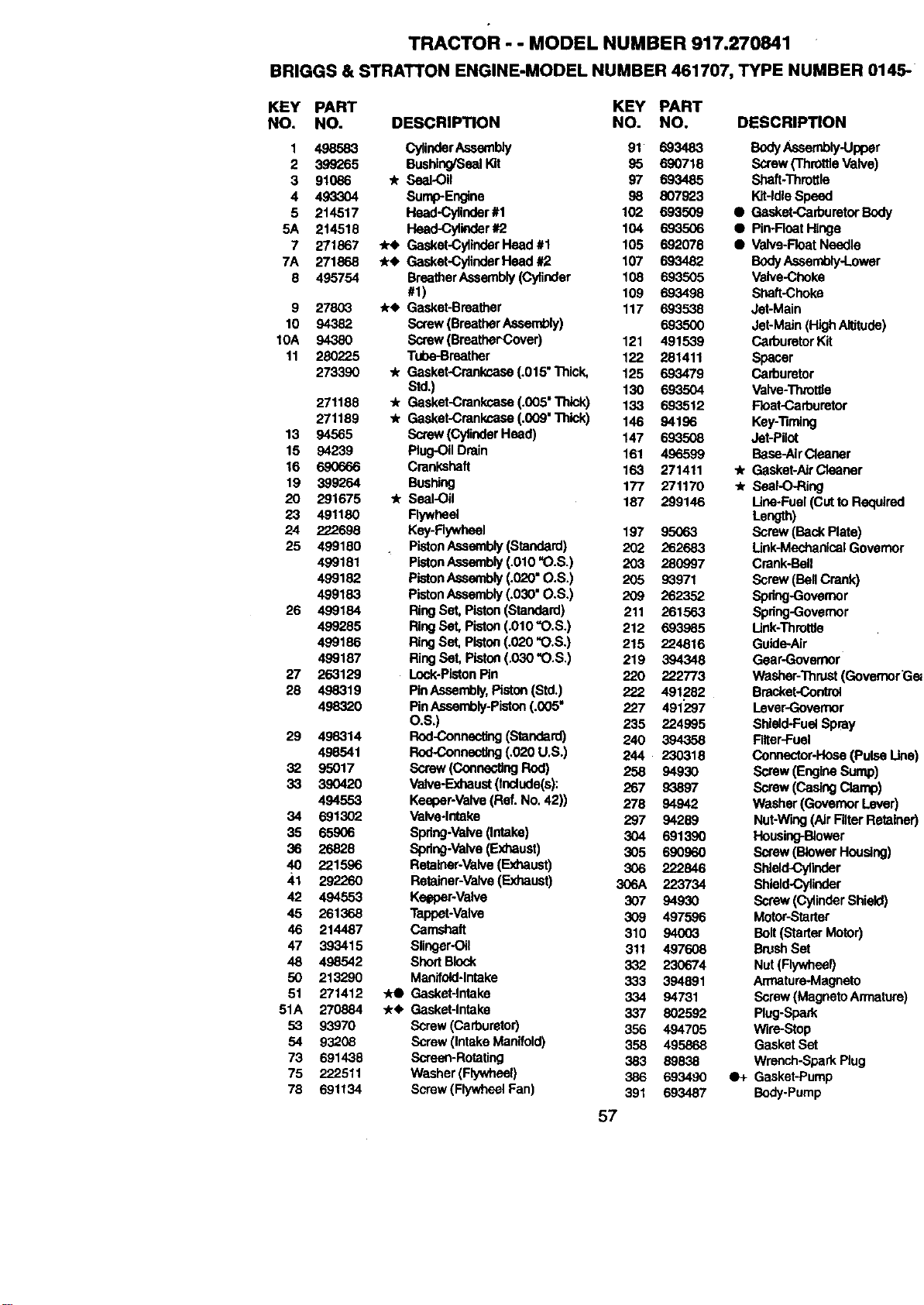
TRACTOR - - MODEL NUMBER 917.270841
BRIGGS & STRATTON ENGINE-MODEL NUMBER 461707, TYPE NUMBER 014,=
KEY PART KEY PART
NO. NO. DESCRIPTION NO. NO. DESCRIPTION
1 498583 CylinderAssembly 91 693483 BodyAssembly-Upper
2 399265 BushingP3eelI_t 95 690718 Screw('ThrottleValve)
3 91086 "k Seal-Oil 97 693485 Shaft-Throttle
4 493304 Surrrp-Engine 98 807_.3 Wit-IdleSpeed
5 214517 Head-Cylinder#1 102 693509 • Gasket-Cad0uretorBody
5A 214518 Head-Cylinder#2 104 693506 • Pin-RoatHinge
7 271867 _re Gasket-CylinderHeed #1 105 692078 • V_ve-Roat Needle
7A 271868 *_. Gasket-CylindorHeed #2 107 693482 BodyAssembly-Lower
8 495754 BreetherAseembly(Cylinder 108 693505 Valve-Choke
#1) 109 693498 Stilt-Choke
9 27803 _r_' Gasket-Breather 117 693538 Jet-Main
10 94382 Screw(BreatherAssembly) 693500 Jet-Main(High Altitude)
10A 94380 Screw(Braather-Cover) 121 491539 C_rburetorKit
11 280225 Tube-Breather 122 281411 Spacer
273390 ,k Gasket-Crankcase(.015" Thick, 125 693479 Carburetor
Std.) 130 693504 Valve-Throttle
271188 "/r Gasket-Crankcase (.005" Thick) 133 693512 Float-Carburetor
271189 , Gasket-Crankcase (.009" Thick) 146 94196 Key-'Rming
13 94565 Screw(Cy_'=derHeed) 147 693508 Jet-Pilot
15 94239 Plug-OilDrain 161 496599 Base-AirCleaner
16 690666 Crankshaft 163 271411 .A.Gasket-AirCleener
19 399264 Bushing 177 271170 "JrSeal-O-Ring
20 291675 "k Seal-Oil 187 299146 Uce-Fuel (CuttORequire<
23 491180 Flywheel Length)
24 222698 Key-Rywheet 197 95063 Screw(BackPlate)
25 499180 PistonAssembly(Standard) 202 262683 Unk-MechanicalGovomo
499181 PistonAssembly(_010"O.S.) 203 280997 Crank-Bell
499182 PistonAssembly(.020" O.S.) 205 93971 Screw(Bell Cr'-tnk)
499183 PistonAssembly(.030" O.S.) 209 262352 Spring-Governor
26 499184 RingSet. Piston(Standard) 211 261563 Spring-Governor
499285 RingSet, Piston(.010"O.S.) 212 693985 Unk-ThK)ttle
499186 RingSet, Piston(.020 "O.S.) 215 224816 Guide-Air
499187 RingSet, Piston(,030 "O.S.) 219 394348 Gear-Governor
27 263129 Lock-PistonPin 220 222773 Washer-Thrust(Governor
28 498319 Pin Assembly,Piston(Std.) 222 491282 Bracket-Cootrol
498320 PinAssembly-Piston(.005" 227 491297 Lever-Governor
O.S.) 235 224995 Shield-FuelSpray
29 498314 Rod-Connec_ (Standard) 240 394358 Rltar-Fuel
498541 Rod-Connec_g (.020 U.S.) 244 230318 Connector-Hose(Pulse L
32 95017 Screw(P_.,o_m_ngRod) 258 94930 Screw(Engine Sump)
33 390420 Valve-Exhaust(Include(s): 267 93897 Screw (CasingClamp)
494553 Keeper-Valve(Raf. No. 42)) 278 94942 Washer (GovernorLever]
34 691302 Valve4otake 297 94289 Nut-Wing(Air FitterReta_
35 65906 Spring-Valve(Intake) 304 691390 Housing-B_ower
36 26828 Spring-Valve (Extlaust) 305 690960 Screw(Bower Housing)
40 221596 Retainer*Valve(Exhaust) 306 222846 Shield-Cylinder
41 292260 Retainer-Valve(FJd'_ust) 306A 223734 Shield-Cylinder
42 494553 Keeper-Valve 307 94930 Screw (CylinderShield)
45 261368 Tappet-Valve 309 497596 Motor-Starter
46 214487 Camshaft 310 9400_ Bolt(Starter Motor)
47 393415 Slinger-Oil 311 497608 Bn_shSet
48 498542 Short Block 332 230674 Nut (Flywheel)
50 213290 Manltold-lntake 333 394891 Armature-Magneto
51 271412 _ Gasket-intake 334 94731 Screw (MagnetoArmatun
51A 270884 -/r4, Gasket-Intake 337 802592 Plug-Spark
53 93970 Screw (Carburetor) 356 494705 Wire-Stop
54 93208 Screw (IntakeManifold) 358 495868 GasketSet
73 691438 Screon-Rotating 383 89838 Wronch-SparkPlug
75 222511 Washer(Flywhest) 386 693490 q_- Gasket-Pump
78 691134 Screw (FlywheelFan) 391 693487 Body-Pump
57

TRACTOR - - MODEL NUMBER 917.270841
BRIGGS & STRATrON ENGINE-MODEL NUMBER 461707, TYPE NUMBER 0145-E1
KEY PART KEY PART
NO. NO. DESCRIPTION NO. NO. DESCRIPTION
392 693491 0+ Spring-PumpDlaphregm
404 223882 Washer(GovernorCrank)
423 94674 Screw(AirCleaner Base)
425 94823 Screw (AirCleaner Cover)
432 693492 0+ Cap*Spring
433 693489 •+ Diaphragm-FuelIbump
434 693493 Cover-Diaphragm
435 693494 Screw (DiaphragmCover)
441 222875 Bracket-OilFill
445 394019 Filter-Air
447 93343 Screw (AirGuideCover)
449 94882 Screw (Oil Fill Bracket),
474 93474 Aitemator
482 93621 Screw (Alternator)
510 497606 Drive-Starter
513 398003 Clutsh-Drive
523 494947 Dipstick
525 495348 Tube-Oil Fill
527 223167 Ciamp-Tube
535 272490 Filter-Air
544 97603 Armature-Starter
552 262332 Bushing(GovernorCrank)
552A 262331 Bushing(GovernorCrank)
562 93853 Bolt-Carriage(Govemor Lever)
569 272645 _ Gasket-Base
572 222892 CoVer-Breather(Cylinder#2)
573 491304 Plate-Back
592 92278 Nut (GovernorLever)
601 95162 Clamp-Hose
615 94296 Retainer(Govemor Crank)
615A 93898 Retainer-GovernorShaft
616 491530 Crank-Governor
634 491287 * Seal-GovernorShaft
634A 271013 Washer-Foam
635 66538 Boot-SparkPlug
637 693510 Washer-Seal
643 496700 Retainer-AirFilter
689 262337 Spring-Friction
697 93585 Screw (DriveCap)
725 280866 Shiald-Hnat
726 91362 Gear-Ring
741 262989 Gear-'nming
783 693059 Geaf-Stattar
797 94010 Nut (StarterTerminal)
797A 693167 Nut (StarterTerminal)
801 394860 Cap-Drive
802 497607 _End +
803 497604 Housing-Starter
807 693511 Spacer
822 693497 Washer-Seal (Throttle Shaft)
847 495715 DIpsSck[rubeAseambLy
851 493880 Terminal-Cable
859 693488 0+ Diaphragm-FuelPump
861 393397 Kit-FuelPump
865 224774 Cover-Air Guide
865A 224775 Cover-AirGuide
868 497656 Seal-Valve
868A 273312 Seal-Valve
869 261463 Seat-Valve(|ntake)
870 262924 Seat-Valve (Exhaust)
671 261961 Bushing-Guide(Exhaust)
231218 Bushing-Guide(Intake)
877 393456 Wlra-Altemator
881 495901 Plate-Cover
918 393815 Ho_e-Vacuum(Cylinder-To-
Impulse Pump)(Cutto Required
Length)
934 94627 Screw (Fan Retainer)
955 693513 Plug-Carburetor
968 225008 Cover-AirCleaner
971 805540 Screw (Upper BodyTo Lower
1005 498157 Fan-Flywheel
1006 224901 Retainer-Fan
1019 496726 Label Kit
1036 499382 Labet KP,-Erniasion
1051 263080 Ring-Retaining
1058 273688 Owner's Manua=
1081 280860 _r Seal-O-Ring
1090 497605 Retainer-Brash
1095 498047 GasketSet-Valve Overhaul
1125 94724 Screw (Cover Plate)
1132 94675 " Screw(Oil Slinger)
1136 94297 Screw (Governor,ContrelRed)
1137 220680 Washer (Governor,Control
Rod)
1138 94298 Nut(Governor,ControlRod
-- 460707-0145-E1Reptanement Engina
IncludedinGasket Set, Ref Number 358.
• IncludedinCarburetorKit,Rel Number 121.
• IncludedinValue Overhaut Kit,Rel Number
1095.
+ Includedin Fuel Pump Kit,Fief Number 861
"JrO•+
NOTE: All componentdimensionsgivenin U,S. inches
1inch =25,4 mm
58

SUGGESTED GUIDE FOR SIGHTING SLOPES FOR SAFE OPERATION
_r _
f -*
SIGHTING
GUIDE
ONLY RIDE UP AND DOWN HILL,
NOT ACROSS HILL
o_
_O
I_lk perate your Tractor up and down the face of slopes (not I
greater than 15°), never across the face. Make turns gradu-
I
ally to prevent tipping or loss of control. Exercise extreme
caution when changing direction on slopes.

For in-home major brand repair service:
Call 24 hoursa day, 7 days a week
1-800-4-MY-H OMEsM(1-800-469-4663)
Para pedir servicio de reparaci6n a domicilio
1-800-676-5811
In Canada for all your service and parts needs call
Au Canada pour tout le service ou les pi_ces
!-800-665-4455
For the repair or replacement parts you need:
Call 6 am-11 pm CST, 7 days a week
PartsDirect sM
1-800-366-PART (1-800-366-7278)
Para ordenar piezas con entrega a domicilio
1-800-659-7084
For the location of a Sears Parts and Repair Center
in your area:
Call 24 Hours a day, 7 days a week
1-800-488-1222
For information on purchasing a Sears Maintenance
Agreement or to inquire about an existing Agreement:
Call 9 am-5 pm, Monday - Saturday
1-800-827-6655
SEARS
HomeCentralsM
169590 Rev. 1 4.28.99 JH Printed in U.S.A


