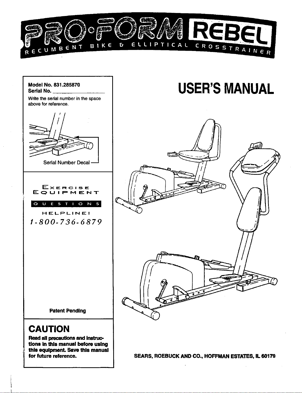
Model No. 831.285870
Serial No.
Writethe sedalnumberinthespace
abovefor reference.
Serial i_
_-----X I_ R C I .._, E:
E q_, U I P M E N T
HELPLINE!
1-800-736-6879
Patent Pending
CAUTION
Read all precautions and Inatruc-
tlons In this manual before using
this equlpmenL Save this manual
for future reference.
USER'SMANUAL
SEARS, ROEBUCK AND CO., HOFFMAN ESTATES, IL 60179
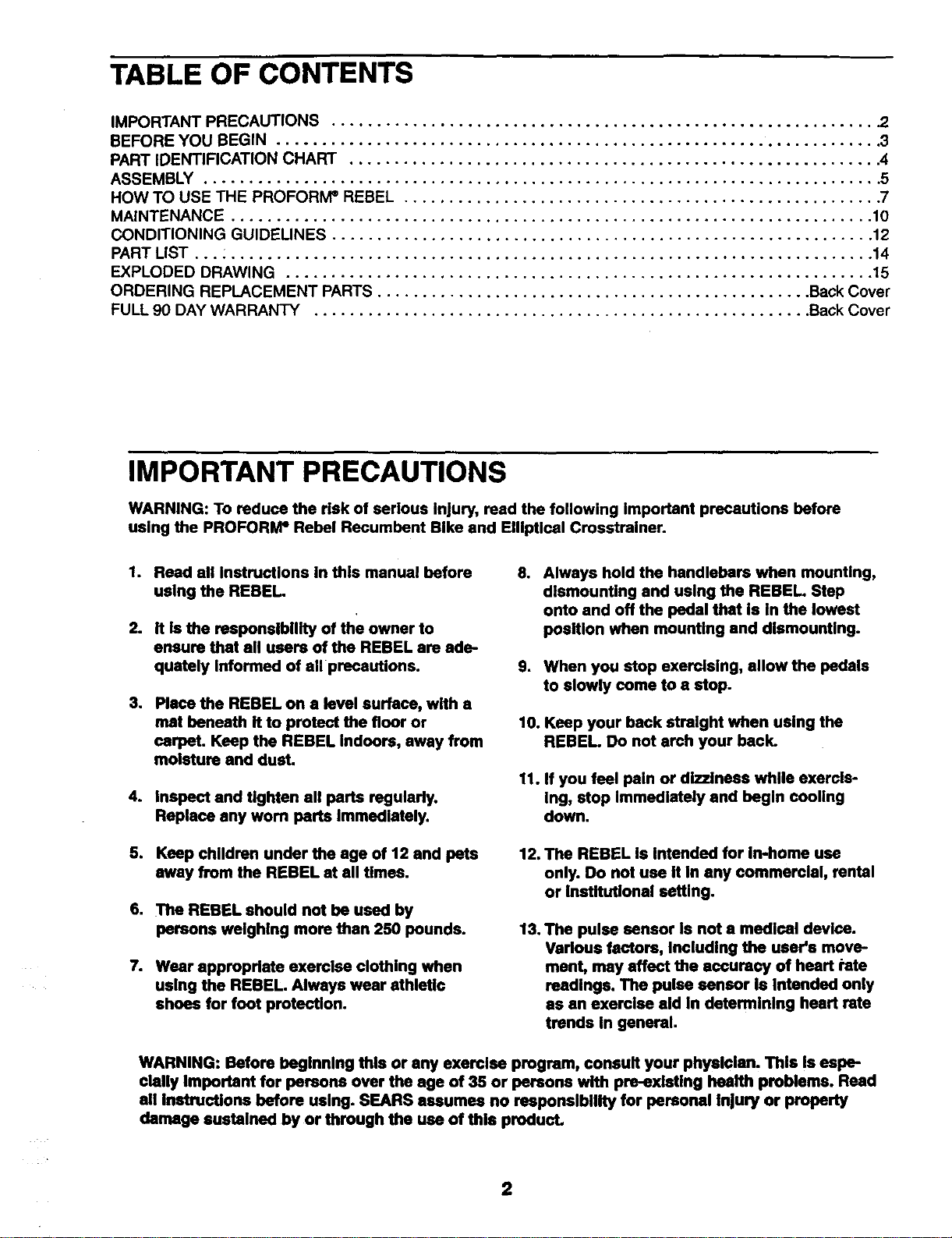
TABLE OF CONTENTS
IMPORTANT PRECAUTIONS ............................................................ .2
BEFORE YOU BEGIN ................................................................... 3
PART IDENTIFICATION CHART ........................................................... 4
ASSEMBLY ........................................................................... 5
HOW TO USE THE PROFORIVP REBEL ..................................................... 7
MAINTENANCE ....................................................................... 10
CONDITIONING GUIDELINES ............................................................ 12
PART LIST ... : ....................................................................... 14
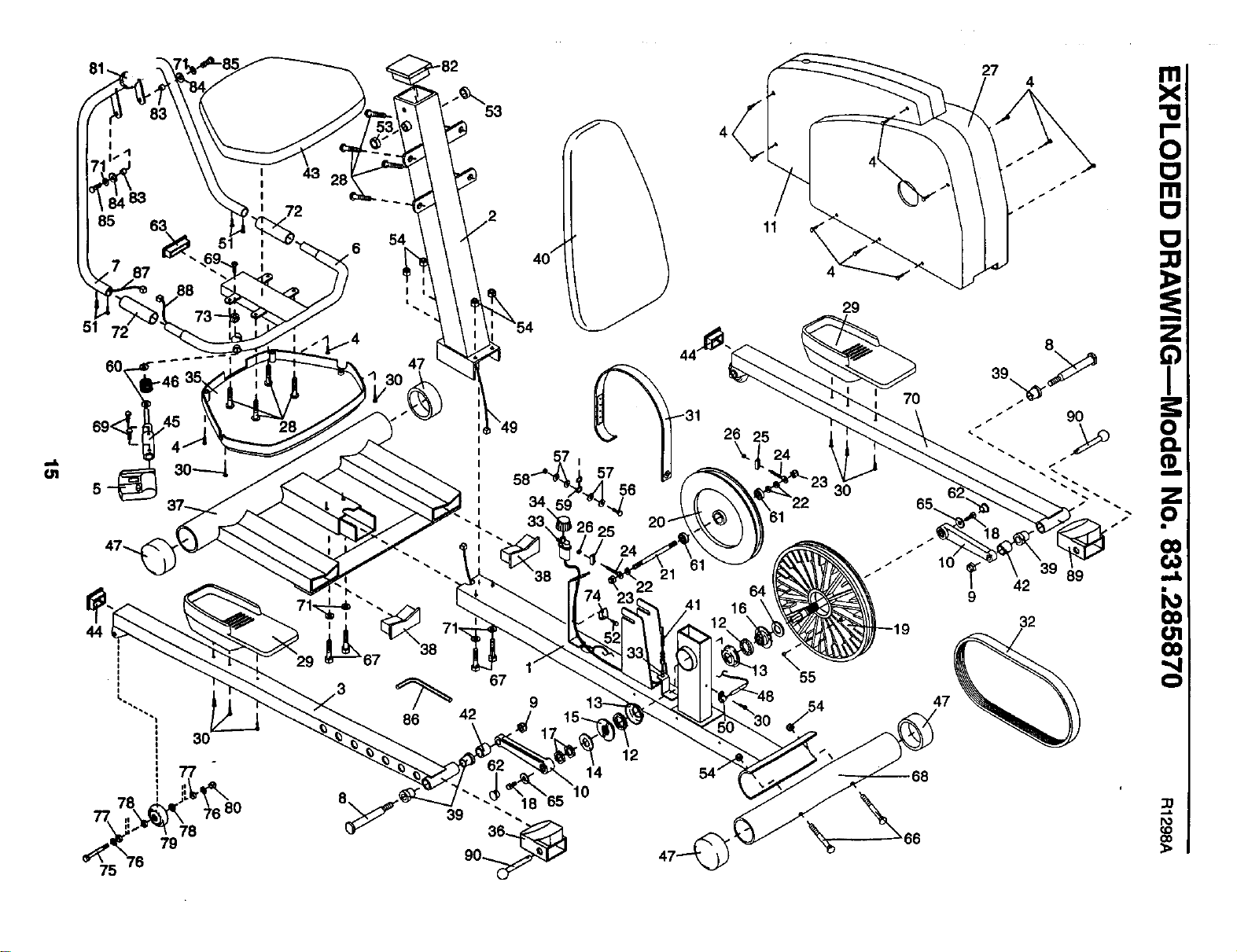
EXPLODED DRAWING ................................................................. 15
ORDERING REPLACEMENT PARTS ................................................ Back Cover
FULL 90 DAY WARRANTY ....................................................... Back Cover
IMPORTANT PRECAUTIONS
WARNING: To reduce the risk of serious Injury, read the following Important precautions before
using the PROFORM e Rebel Recumbent Bike and EIIIptlcel Crosstralner.
.
2.
Reed all Instructions in this manual before
using the REBEL.
It Is the responsibility of the owner to
ensure that ell users of the REBEL are ade.
quately Informed of all precautions.
3. Place the REBEL on • level surface, with a
mat beneath it to protect the floor or
carpeL Keep the REBEL Indoors, away from
moisture end dust.
4. Inspect and tighten all ports regularly.
Replace any worn ports Immedlstely.
o
Always hold the handlebars when mounUng,
dismounting and using the REBEL. Step
onto and off the pedal that is In the lowest
position when mounting and dismounting.
9. When you stop exercising, allow the pedals
to slowly come to e stop.
10. Keep your back strelght when using the
REBEL. Do not arch your back.
11. If you feel pain or dizziness while exercis-
Ing, stop Immediately and begin cooling
down.
5. Keep children under the age of 12 end pets
away from the REBEL st all times.
6. The REBEL should nut be used by
persons weighing more than 250 pounds.
7. Wear appropriate exerclee clothing when
using the REBEL. Always wear athletic
shoes for foot protection.
12. The REBEL is Intended for In-home use
only. Do not use it In any commerelal, rental
or Institutional setting.
13. The pulse sensor Is nut e medical device.
Various factors, Including the user's move-
ment, may affect the accuracy of heart rote
readings. The pulse sensor Is Intended only
as an exerelee aid In determining heart rate
trends in general.
WARNING: Before beginning this or any exercise program, consult your physician. This Is eepe-
clally Important for persons over the age of 35 or persons with pre-existing health problems. Read
all Instructions before using. SEARS assumes no responsibility for personal Injury or property
damage sustained by or through the use of this product.
2
BEFORE YOU BEGIN
Congratulations for selecting the revolutionary PRO-
FORIvP REBEL Recumbent Bike and Elliptical
Cmsstrainer. The REBEL is an incredibly smooth
exerciser that moves your feet in a natural elliptical
path, minimizing the impact on your knees and ankles.
The unique REBEL can easily be converted from an
ellipticalcrosstrainer to a recumbent bike, giving you
two machines in one. Welcome to a whole new wodd
of natural, elliptical-motion exercise from PROFORM.
For your benefit, read this manual carefully before
you use the REBEL. Ifyou have additional questions,
please call ourtoll-free HELPLINE at 1-800736-6879,
Monday through Saturday, 7 a.m. until 7 p.m. Central
Time (excluding holidays). To help us assist you,
please note the product model number and serial
number before calling. The model number is
831.285870. The sedal number can be found on a
decal attached to the REBEL (see the front cover of
this manual).
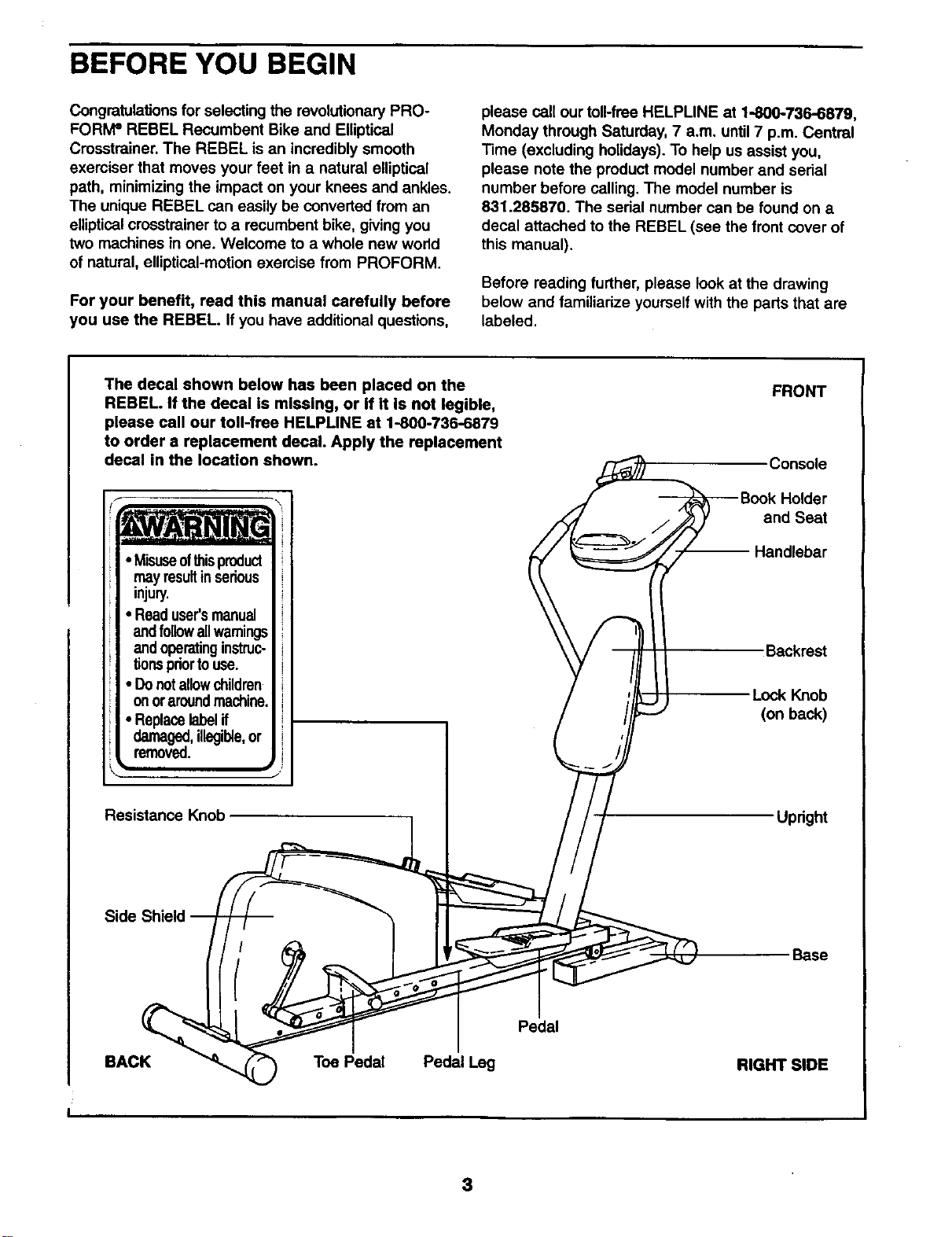
Before reading further, please look at the drawing
below and familiadze yourself with the parts that are
labeled.
The decal shown below has been placed on the FRONT
_ Console
_Book Holder
,_,_Z_. //_ and Seat
_._,/ _ -- Handlebar
injury. \\ t_
Readl
-,o \\ F II
andoperatinginstruc- \ \ / _ll I I Backrest
tionspdortouse. V /11 It
Donotallowchildren / '// I I .
on 0raroundmachine. / i/L_J'J--- -- L_ok bK_ac_b
• Replacelabelif / i/F-- _ I
damaged,illegible,or { _/I
Side Shield _ _, _ _ / j
I Pedal
BACK _ Toe Pedal Pedal Leg RIGHT SIDE
I
REBEL. If the decal is missing, or if it is not legible,
please call our toll-free HELPLINE at 1-800-736-6879
to order a replacement decal. Apply the replacement
decal in the location shown.
• Misuseof_is product
may resultinserious
• Readuser'smanual
and followallwamings
• Donotallowchildren
onoraroundmachine.
Resistance Knob
3
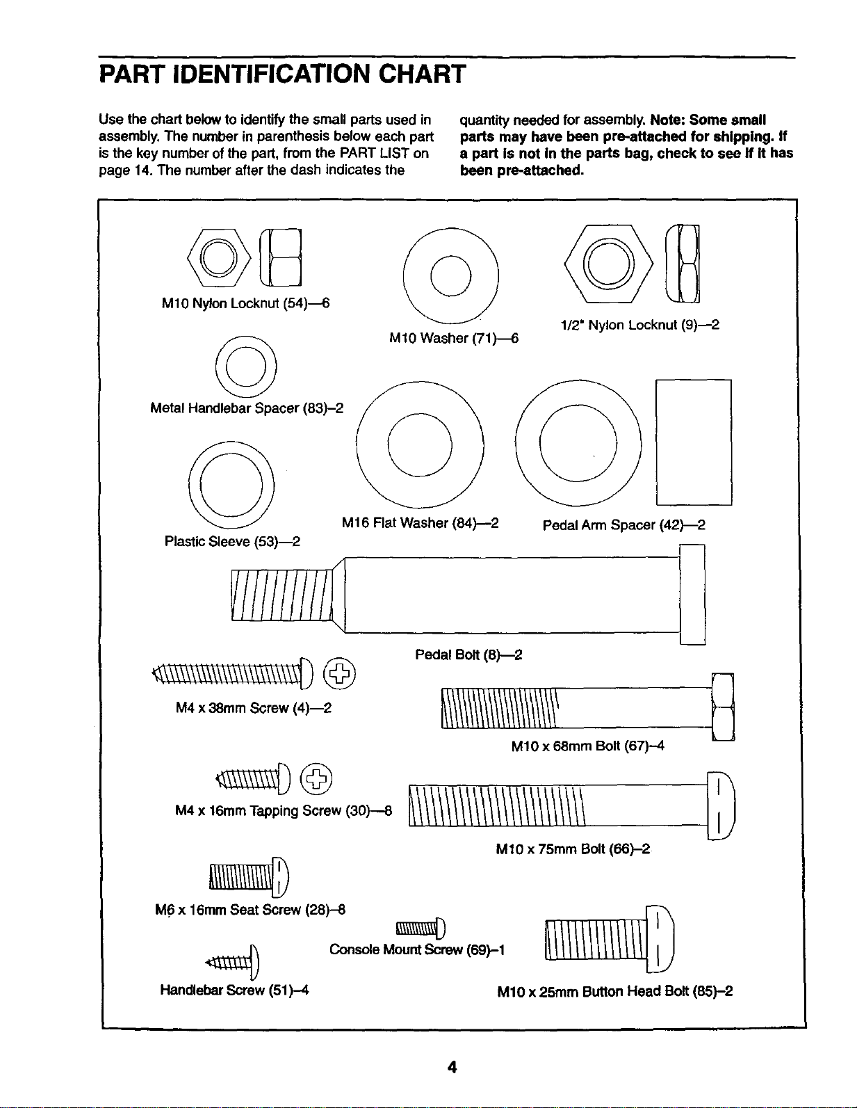
PART IDENTIFICATION CHART
Use the chart below to identify the small parts used in
assembly. The number in parenthesis below each part
is the key number of the part, from the PART LIST on
page 14. The number after the dash indicates the
quantity needed for assembly. Note: Some small
parts may have been pre-.attached for shipping. If
a part is not in the parts bag, check to see if it has
been pre-attached.
MIO Nylon Locknut (54)_
©
Metal Handlebar Spacer (83)-2
MIO Washer (71)4
1/2" Nylon Locknut (9)--2
M16 Flat Washer (84)--2
Plastic Sleeve (53)--2
M4 x 38ram Screw (4)_2
Pedal Bolt (8)--2
Pedal Arm Spacer (42)-2
MIO x 68mm Bolt (67)--4
M4 x 16mm Tapping Screw (30)--8
M10 x 75mm Bolt (66)-2
M6 x 16ram Seat Screw (28)-8
) Console Mount Screw 169)-1
Handlebar Screw (51)-4 M10 x 25mm Button Head Bolt (85)-2
4
ASSEMBLY
Assembly requires two persons. Place all parts of the PROFORM ®REBEL in a cleared area and remove the
packing materials. Do not dispose of the packing materials until assembly is completed.
Assembly requires a phillips screwdriver _, two adjustable wrenches _ and a
rubber mallet _--_-_ (none of these are included).
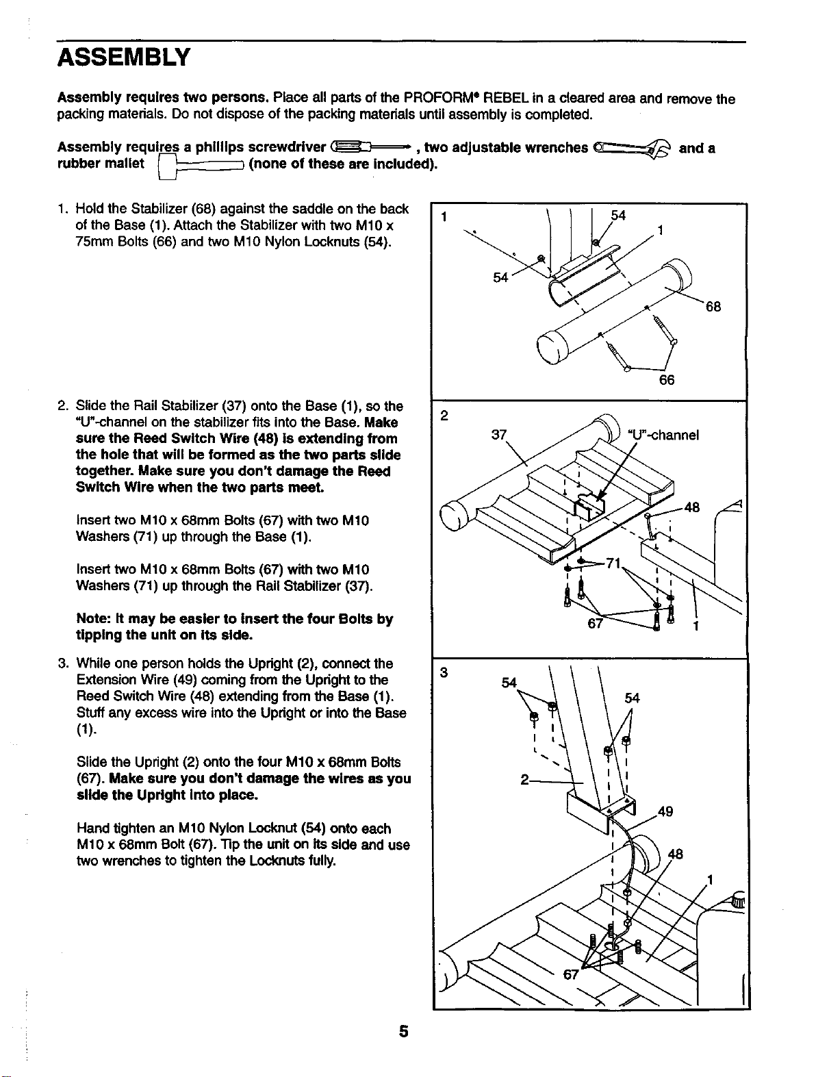
1. Hold the Stabilizer (68) against the saddle on the back
of the Base (1). Attach the Stabilizer with two M1O x
75ram Bolts (66) and two M10 Nylon Locknuts (54).
.
.
Slide the Rail Stabilizer (37) onto the Base (1), so the
=U"-channel on the stabilizer fits into the Base. Make
sure the Reed Switch Wire (48) is extending from
the hole that will be formed as the two parts slide
together. Make sure you don't damage the Reed
Switch Wire when the two parts meet.
Insert two M10 x 68mm Bolts (67) with two M10
Washers (71) up through the Base (1).
Insert two M1O x 68mm Bolts (67) with two M1O
Washers (71) up through the Rail Stabilizer (37).
Note: It may be easier to insert the four Bolts by
tipping the unIt on Its side.
While one person holds the Updght (2), connect the
Extension Wire (49) coming from the Upright to the
Reed Switch Wire (48) extending from the Base (1).
Stuff any excess wire intothe Updght or into the Base
(1).
Slide the Upright (2) onto the four M10 x 68mm Bolts
(67). Make sure you don't damage the wires as you
slide the Upright into place.
Hand tighten an M10 Nylon Locknut (54) onto each
M10 x 68mm Bolt (67). "13pthe unit on its side and use
two wrenches to tighten the Locknuts fully.
2
3
54
66
37 =U'-channel
48
68
5
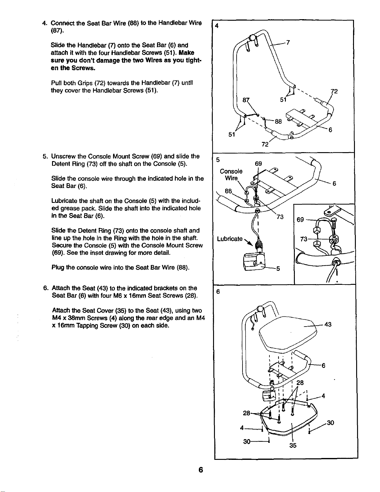
4. Connect the Seat Bar Wire (88) to the Handlebar Wire
(87).
Slide the Handlebar (7) onto the Seat Bar (6) and
attach it with the four Handlebar Screws (51). Make
sure you don't damage the two Wlres as you tight-
en the Screws.
Pull both Grips (72) towards the Handlebar (7) until
they cover the Handlebar Screws (51).
5. Unscrew the Console Mount Screw (69) and slide the
Detent Ring (73) off the shaft on the Console (5).
Slide the console wire through the indicated hole in the
Seat Bar (6).
Lubricate the shaft on the Console (5) with the includ-
ed grease pack. Slide the shaft intothe indicated hole
in the Seat Bar (6).
Slide the Detent Ring (73) onto the console shaft and
line up the hole in the Ring with the hole in the shaft.
Secure the Console (5) with the Console Mount Screw
(69). See the inset drawing for more detail.
Plug the console wire intothe Seat Bar Wire (88).
6. Attach the Seat (43) to the indicated brackets on the
Seat Bar (6) with four M6 x 16mm Seat Screws (28).
Attach the Seat Cover (35) to the Seat (43), using two
M4 x 38mm Screws (4) along the rear edge and an M4
x 16mm Tapping Screw (30) on each side.
4
51
72
6
28
35
6
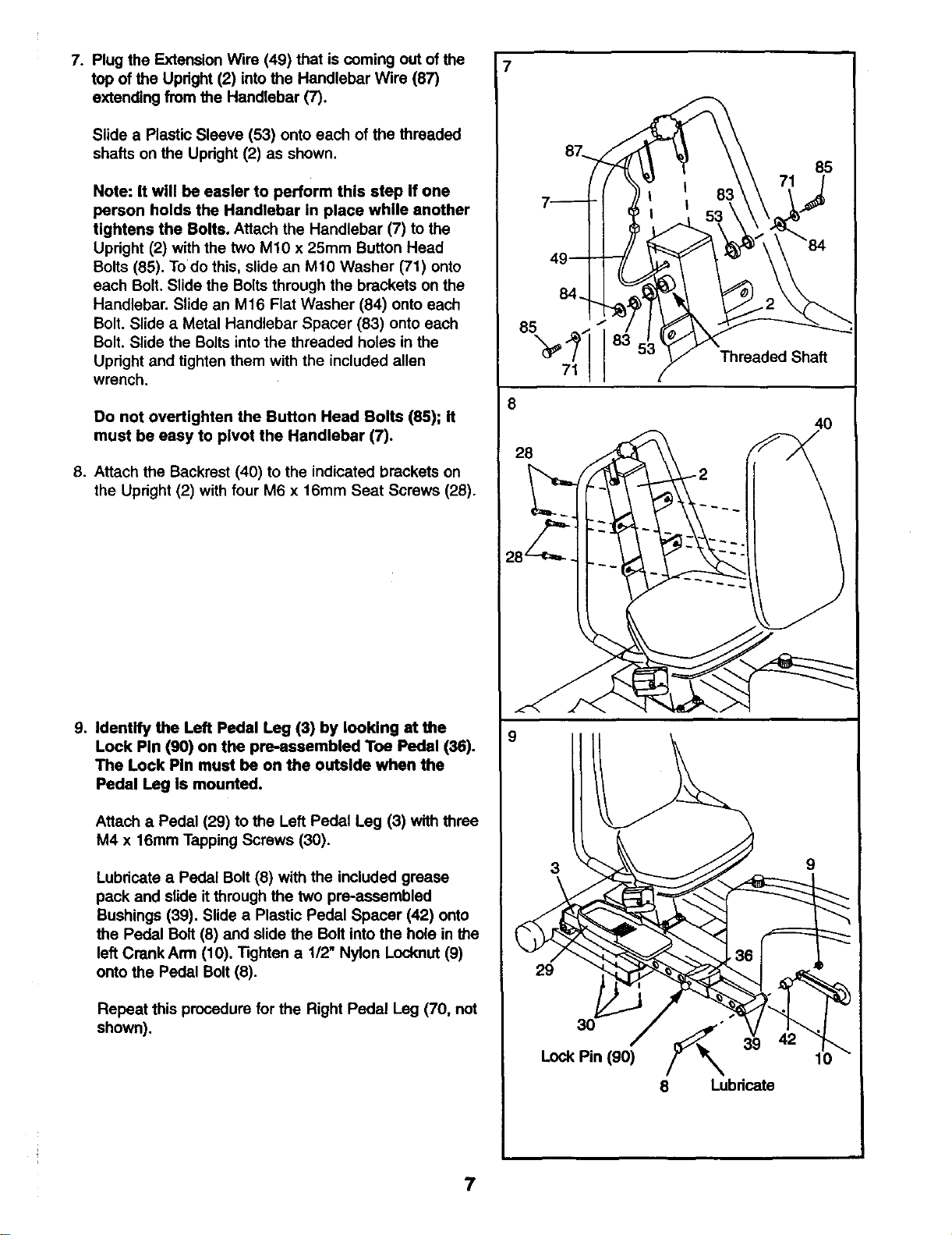
7. Plug the Extension Wire (49) that is coming out of the
top of the Upright (2) into the Handlebar Wire (87)
extending from the Handlebar (7).
Slide a Plastic Sleeve (53) onto each of the threaded
shafts on the Upright (2) as shown.
Note: It will be easier to perform this step If one
person holds the Handlebar in place white another
tightens the Bolts. Attach the Handlebar (7) to the
Upright (2) with the two M10 x 25mm Button Head
Bolts (85). Todo this, slide an M10 Washer (71) onto
each Bolt. Slide the Bolts through the brackets on the
Handlebar. Slide an M16 Flat Washer (84) onto each
Bolt. Slide a Metal Handlebar Spacer (83) onto each
Bolt. Slide the Bolts into the threaded holes in the
Upright and tighten them with the included allen
wrench.
Do not overUghten the Button Head Bolts (85); It
must be easy to pivot the Handlebar (7).
8. Attach the Backrest (40) to the indicated brackets on
the Upright (2) with four M6 x 16mm Seat Screws (28).
9. Identify the Left Pedal Leg (3) by looking at the
Lock Pin (90) on the pre_ssembled Toe Pedal (36).
The Lock Pin must be on the outside when the
Pedal Leg is mounted.
Attach a Pedal (29) to the Left Pedal Leg (3) with three
M4 x 16mm Tapping Screws (30).
Lubricate a Pedal Bolt (8) with the included grease
pack and slide it through the two pre-assembled
Bushings (39). Slide a Plastic Pedal Spacer (42) onto
the Pedal Bolt (8) and slide the Bolt into the hole in the
left CrankArm (10). Tighten a 1/2" Nylon Locknut (9)
onto the Pedal Bolt (8).
Repeat this procedure for the Right Pedal Leg (70, not
shown).
85
71
8
28
8;
Threaded Shaft
4O
8 Lubricate
7
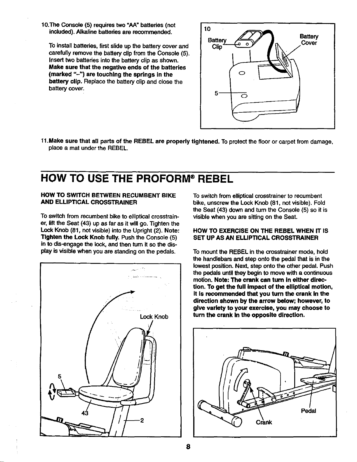
10.The Console (5) requires two =AA" batteries (not
included). Alkaline battedes are recommended.
To install batteries, first slide up the battery cover and
carefully remove the battery clip from the Console (5).
Insert two batteries intothe battery clip as shown.
Make sure that the negative ends of the batteries
(marked "-") are touching the springs In the
battery clip. Replace the battery clip and close the
battery cover.
10
Battery
Battery Cover
Clip
11.Make sure that all parts of the REBEL are properly tightened. To protect the floor or carpet from damage,
place a mat under the REBEL.
HOW TO USE THE PROFORM ®REBEL
HOW TO SWITCH BETWEEN RECUMBENT BIKE
AND ELLIPTICAL CROSSTRAINER
To switch from recumbent bike to elliptical crosstrain-
er, lift the Seat (43) up as far as it will go. Tighten the
Lock Knob (81, not visible) into the Upright (2). Note:
TIghten the Lock Knob fully. Push the Console (5)
in to dis-engage the lock, and then turn it so the dis-
play is visible when you are standing on the pedals.
Lock Knob
To switch from elliptical crosstrainer to recumbent
bike, unscrew the Lock Knob (81, not visible). Fold
the Seat (43) down and turn the Console (5) so it is
visible when you are sitting on the Seat.
HOW TO EXERCISE ON THE REBEL WHEN IT IS
SET UP AS AN ELUPTICAL CROSSTRAINER
To mount the REBEL in the crosstreiner mode, hold
the handlebars and step onto the pedal that is in the
lowest position. Next, step onto the other pedal. Push
the pedals until they begin to move with a continuous
motion. Note: The crank can turn In either direc-
tion. To get the full Impact of the elliptical motion,
it Is recommended that you turn the crank in the
direction shown by the arrow below; however, to
give variety to your exercise, you may choose to
turn the crank In the opposite dlraction.
8
To dismount the REBEL, allow the pedals to slowly
come to a stop. CAUTION: The REBEL does not
have a freewheel; the pedals will contlnue to
move until the flywheel stops. When the pedals are
_tationa_y, step off the highest pedal first.Then, step
offthe lowest pedal.
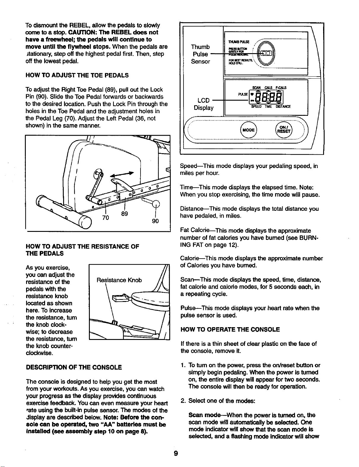
HOW TO ADJUST THE TOE PEDALS
To adjust the Right Toe Pedal (89), pull out the Lock
Pin (90). Slide the Toe Pedal forwards or backwards
to the desired location. Push the Lock Pin through the
holes in the Toe Pedal and the adjustment holes in
the Pedal Leg (70). Adjust the Left Pedal (36, not
shown) in the same manner.
Thumb _==n= : _
Pulse _ _ _
f/
Sensor \._
LCD
Display
SCaN C/LS F-CALS
SPEED TIME _STAt_E
........................................................................ ..,,
89
7O
90
HOW TO ADJUST THE RESISTANCE OF
THE PEDALS
As you exercise,
you can adjust the
resistance of the
pedals with the
resistance knob
located as shown
here. To increase
the resistance, turn
the knob clock-
wise; to decrease
the resistance, tum
the knob counter-
clockwise.
Resistance Knob
DESCRIPTION OF THE CONSOLE
The console is designed to help you get the most
from your workouts. As you exercise, you can watch
your progress as the display provides continuous
exercise feedback. You can even measure your heart
rate using the built-in pulse sensor. The modes of the
Jisplay are descdbed below. Note: Before the con-
sole can be operated, two "AA" betterles must be
Installed (see assembly step 10 on page 8).
Speed--This mode displays your pedaling speed, in
miles per hour.
Time--This mode displays the elapsed time. Note:
When you stop exercising, the time mode will pause.
Distance--This mode displays the total distance you
have pedaled, in miles.
Fat Calorie---This mode displays the approximate
number of fat calodes you have bumed (see BURN-
ING FATon page 12).
Calorie---This mode displays the appmxirnate number
of Calodes you have burned.
Scan--This mode displays the speed, time, distance,
fat calode and calode modes, for 5 seconds each, in
a repeating cycle.
Pulse---This mode displays your heart rate when the
pulse sensor is used.
HOW TO OPERATE THE CONSOLE
If there is a thin sheet of clear plasticon the face of
the console, remove it.
1,
To tum on the power, press the on/reset button or
simply begin pedaling. When the power is tumed
on, the entire display willappear for two seconds.
The console willthen be reedy for operation.
2. Select one of the modes:
Scan mode--When the power is tumed on, the
scan mode will automatically be selected. One
mode indicator will show that the scan mode is
selected, and a flashing mode indicator will show
9
which mode is
currently dis-
played. Note: If
a different
mode is select-
ed, you can
select the scan
mode again by
repeatedly
SCAN CAbS F-CALS
SPEED TIlE DISTANCE
------'--" Mode Indicators :
pressing the mode button.
Speed, time, distance, fat calorie or calorie
mode_To select one of these modes for continu-
ous display, press the mode button repeatedly. The
mode indicators will show which mode is selected.
(Make sure that the scan mode is not selected.)
3. To measure your pulse, stop pedaling and place
your thumb on the pulse sensor as shown. The
pulse sensor is pressure-activated---fully press
down the pulse sensor. Do not press too herd, or
the circulation In your thumb wtll be restricted,
and your pulse will not be detected. Next, slightly
raise your thumb until the heart-shaped indicator in
the LCD display flashes steadily. Hold your thumb
at this level. After 5 to 10 seconds, three dashes
will appear in the display
and your pulse will be
shown. Hold your thumb
on the sensor for another
15 seconds for the most
accurate reading. If the
displayed pulse appears
to be too high or too low,
or if your pulse is not dis-
played, lift your thumb off
the sensor and allow the
display to reset. Press
down again on the sensor as described above.
Make sure that your thumb ispositioned as shown,
and that you are applying the proper amount of
pressure to the pulse sensor.Try the sensor several
times until you become familiar with it.
4. To reset the display, press the on/reset button.
5. The console has an "auto-off" feature. If the
pedals are not moved and the console buttons
are not pressed for four minutes, the power will
turn off automatically to conserve the batteries.
MAINTENANCE
CONSOLE TROUBLE-SHOOTING
if the console does not function properly, the batteries
should be replaced. To replace the batteries, see
assembly step 10 on page 8. In addition, make sure
that the console wire is connected to the seat bar
wire. See assembly step 5 on page 6.
HOW TO REMOVE THE SIDE SHIELDS
For all of the following steps, one or beth Side
Shields (11 and 27) must be removed.
To remove the Left Side Shield (11), unscrew the 1/2"
Nylon Lockout (9) and remove the Pedal Bolt (8) and
the Plastic Pedal Spacer (42) from the Left Pedal Leg
(3). Unscrew the seven M4 x 38ram Screws (4) from
the Left Side Shield. Gently pull the Left Side Shield
out and to the side, so the Crank Arm (10) fits
through the hole in the Side Shield.
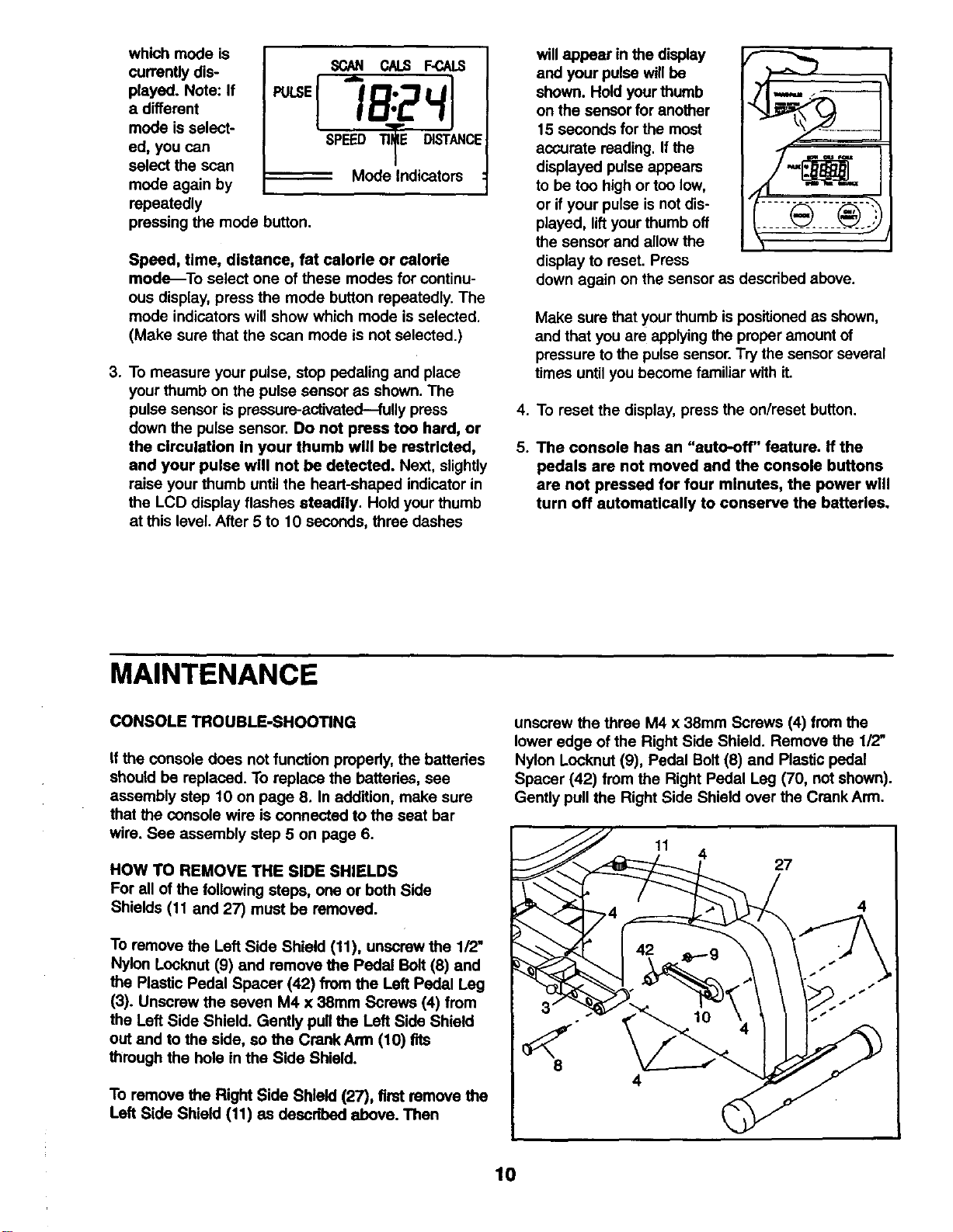
To remove the Right Side Shield (27), first remove the
Left Side Shield (11) as described above. Then
unscrew the three M4 x 38mm Screws (4) from the
lower edge of the Right Side Shield. Remove the 1/2"
Nylon Locknut (9), Pedal Bolt (8) and Plastic pedal
Spacer (42) from the Right Pedal Leg (70, not shown).
Gently pull the Right Side Shield over the Crank Arm.
11
4
27
4
4
10
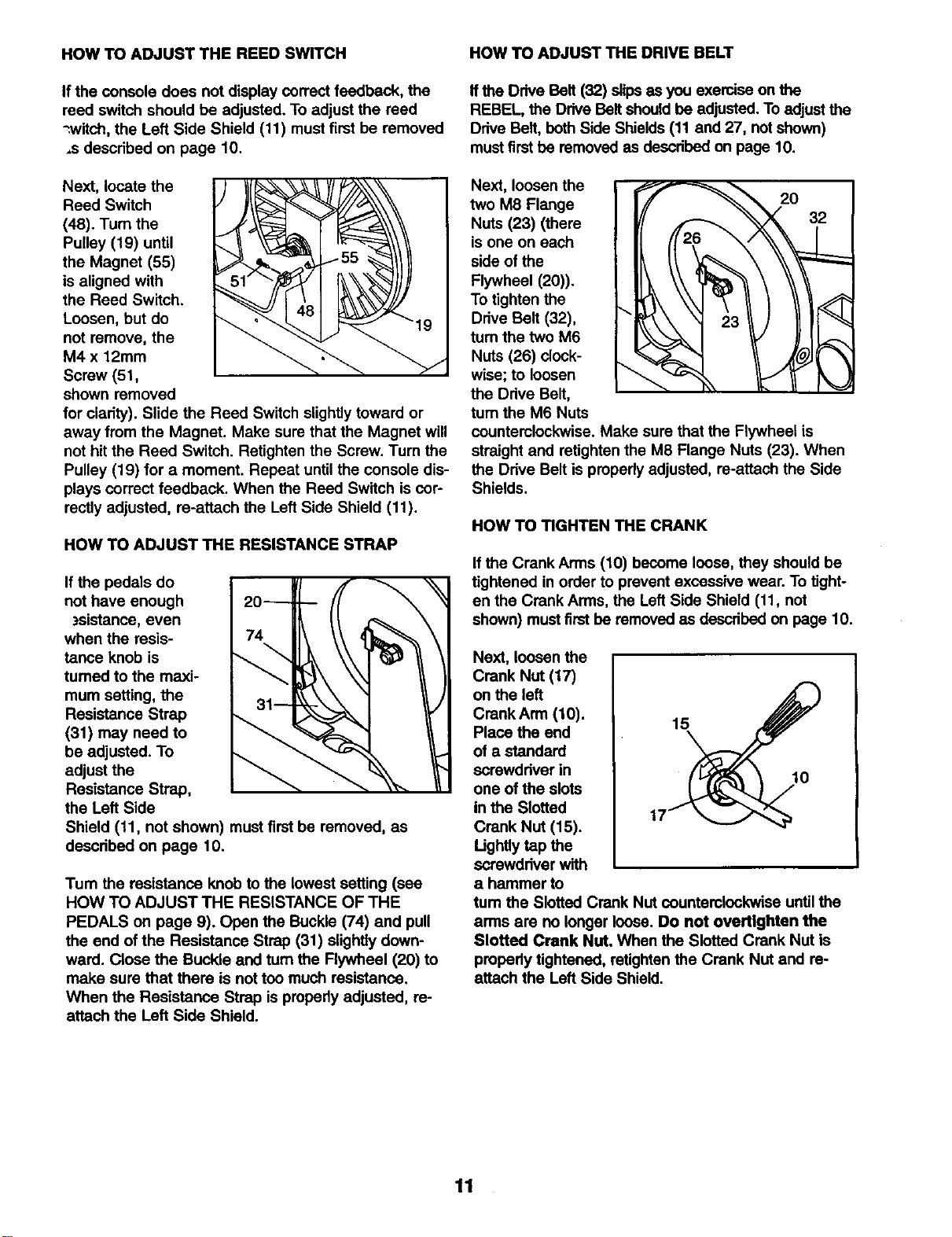
HOW TO ADJUST THE REED SWITCH
If the console does not display correct feedback, the
reed switch should be adjusted. To adjust the reed
-.witch, the Left Side Shield (11) must first be removed
,s described on page 10.
Next, locate the
Reed Switch
(48). Turn the
Pulley (19) until
the Magnet (55)
is aligned with
the Reed Switch.
Loosen, but do 19
not remove, the
M4 x 12mm
Screw (51,
shown removed
for clarity). Slide the Reed Switch slightly toward or
away from the Magnet. Make sure that the Magnet will
not hit the Reed Switch. Retighten the Screw. Turn the
Pulley (19) for a moment. Repeat until the console dis-
plays correct feedback. When the Reed Switch is cor-
rectly adjusted, re-attach the Left Side Shield (11).
HOW TO ADJUST THE RESISTANCE STRAP
If the pedals do
not have enough
zsistance, even
when the resis-
tance knob is
turned to the maxi-
mum setting, the
Resistance Strap
(31) may need to
be adjusted. To
adjust the
Resistance Strap,
the Left Side
Shield (11, not shown) mustfirst be removed, as
described on page 10.
Tum the resistance knob to the lowest setting (see
HOW TO ADJUST THE RESISTANCE OF THE
PEDALS on page 9). Open the Buckle (74) and pull
the end of the Resistance Strap (31) slightly down-
ward. Close the Buckle and turn the Flywheel (20) to
make sure that there is not too much resistance,
When the Resistance Strap is properly adjusted, re-
attach the Left Side Shield.
HOW TO ADJUST THE DRIVE BELT
If the Drive Belt (32) slipsas you exercise on the
REBEL, the Drive Belt should be adjusted.To adjust the
Drive Belt, bothSide Shields (11 and 27, not shown)
mustfirst be removed as described on page 10.
Next, loosen the
two M8 Flange
Nuts (23) (there
is one on each
side of the
Flywheel (20)).
To tighten the
Drive Belt (32),
turn the two M6
Nuts (26) clock-
wise; to loosen
the Drive Belt,
turn the M6 Nuts
counterclockwise. Make sure that the Flywheel is
straight and retighten the M8 Flange Nuts (23). When
the Drive Belt is properly adjusted, re-attach the Side
Shields.
HOW TO TIGHTEN THE CRANK
If the Crank Arms (10) become loose, they should be
tightened in order to prevent excessive wear. To tight-
en the Crank Arms, the Left Side Shield (11, not
shown) mustfirst be removed as described on page 10.
Next, loosen the
Crank Nut (17)
on the left
Crank Arm (10), 15
Place the end
of a standard
screwdriver in 10
one of the slots
in the Slotted
Crank Nut (15).
Ughtly tap the
screwdriver with
a hammer to
tum the Slotted Crank Nut counterclockwise until the
arms are no longer loose. Do not overtlghten the
Slotted Crank Nut, When the Slotted Crank Nut is
properly tightened, retightenthe Crank Nut and re-
attach the Left Side Shield.
11
CONDITIONING GUIDELINES
The following guidelines will help you to plan your
exercise program. Remember that proper nutrition and
adequate rest are essential for successful results.
WARNING: Before beginning this or any exercise
program, consult your physician. This is especial-
ly Important for Individuals over the age of 35 or
Individuals with pre-existing health problems.
WARNING: The pulse sensor is not a medical
device. Various factors, including the user's move-
ment, may affect the accuracy of heart rate read-
ings. The pulse sensor Is intended only as an
exercise aid in determining heart rate trends in
general.
WHY EXERCISE?
Exercise has proven essential for good health and
well-being. Participation in a well-reunded exercise
program helps to develop a stronger and more effi-
cient head, improved respiratory function, increased
stamina, better weight management, increased ability
to handle stress, and greater serf-esteem.
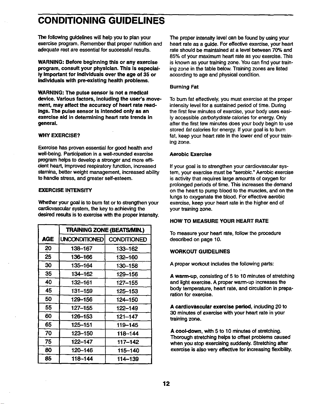
EXERCISE INTENSITY
Whether your goal is to bum fat or to strengthen your
cardiovascular system, the key to achieving the
desired results is to exercise with the proper intensity.
TRAINING ZONE (BEATS/MIN.)
AGE UNCONDITIONED CONDITIONED
20 138-167 133-162
25 136-166 132-160
30 135-164 130-158
35 134-162 129-156
40 132-161 127-155
45 131-159 125-153
50 129-156 124-150
55 127-155 122-149
60 126-153 121-147
65 125-151 119-145
70 123-150 118-144
75 122-147 117-142
80 120-145 115-140
85 118-144 114-139
The proper intensity level can be found by using your
heart rate as a guide. For effective exercise, your heart
rate should be maintained at a level between 70% and
85% of your maximum heart rate as you exemise. This
is known as your training zone. You can find your train-
ingzone in the table below. Training zones are listed
according to age and physical condition.
Burning Fat
To bum fat effectively, you must exercise at the proper
intensity level for a sustained period of time. During
the first few minutes of exercise, your body uses easi-
ly accessible carbohydrate calodes for energy. Only
after the first few minutes does your body begin to use
stored fat calories for energy, if your goal is to bum
fat, keep your heart rate in the lower end of your train-
ing zone.
Aerobic Exercise
If your goal is to strengthen your cardiovascular sys-
tem, your exercise must be "aerobic." Aerobic exercise
is activity that requires large amounts of oxygen for
prolonged periods of time. This increases the demand
on the heart to pump blood to the muscles, and on the
lungs to oxygenate the blood. For effective aerobic
exercise, keep your heart rate in the higher end of
your training zone.
HOW TO MEASURE YOUR HEART RATE
To measure your heart rate, follow the procedure
described on page 10.
WORKOUT GUIDELINES
A proper workout includes the following pads:
A warm-up, consisting of 5 to 10 minutes of stretching
and light exercise. A proper warm-up increases the
body temperature, heart rate, and circulation in prepa-
ration for exercise.
A cardiovascular exercise period, including 20 to
30 minutes of exercise with your heart rate in your
training zone.
A cool-down, with 5 to 10 minutes of stretching.
Thorough stretching helps to offset problems caused
when you stop exercising suddenly. Stretching after
exercise is also very effective for increasing flexibility.
12
EXERCISE FREQUENCY
To maintain or improve your condition, plan three
workouts each week, with at least one day of rest
etween workouts. After a few months of regular
exercise, you may complete up to five workouts each
week, if desired. Find the best time of day for your
workouts, and then stick with it.
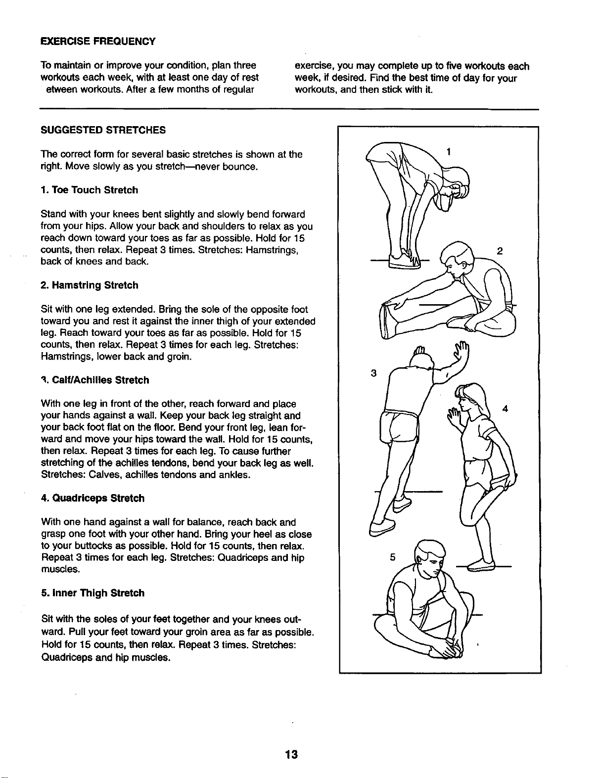
SUGGESTED STRETCHES
The correct form for several basic stretches is shown at the
dght. Move slowly as you stretch--never bounce.
1. Toe Touch Stretch
Stand with your knees bent slightly and slowly bend forward
from your hips. Allow your back and shoulders to relax as you
reach down toward your toes as far as possible. Hold for 15
counts, then relax. Repeat 3 times. Stretches: Hamstdngs,
back of knees and back.
2. Hamstring Stretch
Sit with one leg extended. Bring the sole of the opposite foot
toward you and rest it against the inner thigh of your extended
leg. Reach toward your toes as far as possible. Hold for 15
counts, then relax. Repeat 3 times for each leg. Stretches:
Hamstdngs, lower back and groin.
"_.Calf/Achilles Stretch
With one leg in front of the other, reach forward and place
your hands against a wall. Keep your back leg straight and
your back foot flat on the floor. Bend your front leg, lean for-
ward and move your hips toward the wall. Hold for 15 counts,
then relax. Repeat 3 times for each leg. To cause further
stretching of the achilles tendons, bend your back leg as well.
Stretches: Calves, achilles tendons and ankles•
4. Quadriceps Stretch
With one hand against a wall for balance, reach back and
grasp one foot with your other hand. Bdng your heel as close
to your buttocks as possible. Hold for 15 counts, then relax.
Repeat 3 times for each log. Stretches: Quaddceps and hip
muscles.
5. Inner Thigh Stretch
Sit with the soles of your feet together and your knees out-
ward. Pull your feet toward your groin area as far as possible.
Hold for 15 counts, then relax. Repeat 3 times. Stretches:
Quaddceps and hip muscles.
• 1
2
3
5
f
13
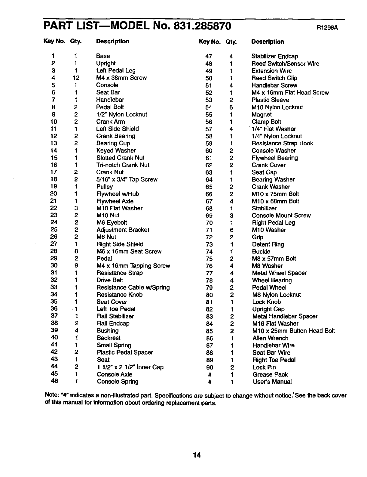
PART LISTmMODEL No. 831.285870 R12 A
Key No. Qty. Description
Key No. Qty. DeecdpUon
1 1 Base 47 4 Stabilizer Endcap
2 1 Upright 48 1 Reed SwitcWSensor Wire
3 1 Left Pedal Leg 49 1 Extension Wire
4 12 M4 x 38mm Screw 50 1 Reed Switch Clip
5 1 Console 51 4 Handlebar Screw
6 1 Seat Bar 52 1 M4 x 16mm Flat Head Screw
7 1 Handlebar 53 2 Plastic Sleeve
8 2 Pedal Bolt 54 6 M10 Nylon Locknut
9 2 1/2" Nylon Locknut 55 1 Magnet
10 2 Crank Arm 56 1 Clamp Bolt
11 1 Left Side Shield 57 4 1/4" Flat Washer
12 2 Crank Bearing 58 1 1/4" Nylon Locknut
13 2 Bearing Cup 59 1 Resistance Strap Hook
14 1 Keyed Washer 60 2 Console Washer
15 1 Slotted Crank Nut 61 2 Flywheel Bearing
16 1 Td-notch Crank Nut 62 2 Crank Cover
17 2 Crank Nut 63 1 Seat Cap
18 2 5/16" x 3/4" Tap Screw 64 1 Beadng Washer
19 1 Pulley 65 2 Crank Washer
20 1 Flywheel w/Hub 66 2 M10 x 75mm Bolt
21 1 Rywheel Axle 67 4 M10 x 68mm Bolt
22 3 M10 Flat Washer 68 1 Stabilizer
23 2 M10 Nut 69 3 Console Mount Screw
24 2 M6 Eyebolt 70 1 Right Pedal Leg
25 2 Adjustment Bracket 71 6 M10 Washer
26 2 M6 Nut 72 2 Gdp
27 1 Right Side Shield 73 1 Detent Ring
28 8 M6 x 16mm Seat Screw 74 1 Buckle
29 2 Pedal 75 2 M8 x 57mm Bolt
30 9 M4 x t6mm Tapping Screw 76 4 M8 Washer
31 1 Resistance Strap 77 4 Metal Wheel Spacer
32 1 Ddve Belt 78 4 Wheel Beadng
33 1 Resistance Cable w/Spdng 79 2 Pedal Wheel
34 1 Resistance Knob 80 2 M8 Nylon Locknut
35 1 Seat Cover 81 1 Lock Knob
36 1 Left Toe Pedal 82 1 Upright Cap
37 1 Rail Stabilizer 83 2 Metal Handlebar Spacer
38 2 Rail Endcap 84 2 M16 Flat Washer
39 4 Bushing 85 2 M10 x 25mm Button Head Bolt
40 1 Backrest 86 1 Allen Wrench
41 1 Small Spring 87 1 Handlebar Wire
42 2 Plastic Pedal Spacer 88 1 Seat Bar wire
43 1 Seat 89 1 Right Toe Pedal
44 2 1 1/2" x 2 1/2" Inner Cap 90 2 Lock Pin
45 1 Console Axle # 1 Grease Pack
46 1 Console Spring # 1 User's Manual
Note: "#' indicates a non-illustrated part. Specifications are subject to change without notice.' See the back cover
of this manual for information about ordedng replacement parts.
14
81-,
33
85
51
51 72
30-----1
47-.
i 3o
77
t
6
43 28
72
54
6
3
8,
53
40/
I I
|
47
33
67 9
86 42
I
57
56
25
22
12
14
4_
11
26 25 24
64
16
55
4
29
3O
27
ORDERING REPLACEMENT PARTS
8F_.ARS
QUESTIONS?
If you find that:
• you need help assembling or
operating the PROFORM"
REBEL Recumbent Bike and
Elliptical Crosstrainer
• a part Is missing
• or you need to schedule repair
service
call our toll-free HELPLINE
1-800-736-6879
Monday-Saturday, 7 am-7 pm
Central Time (excluding holidays)
REPLACEMENT
PARTS
If parts become worn and need to
be replaced, call the following toll-
free number
1-800-FON-PART (366-7278)
The model number and serial number of your PROFORM e
REBEL Recumbent Bike and Elliptical Crosstrainer are listedon
a decal attached to the frame. See the front cover of this manual
to find the location of the decal.
All replacement parts are available for immediate purchase or
special order when you visit your nearest SEARS Service Center.
To request service or to order parts by telephone, call the toll-free
numbers listed at the left.
When requesting help or service, or ordering parts, please be
prepared to provide the following information:
• The MODEL NUMBER of the product (831.285870).
• The NAME of the product (PROFORk, P REBEL Recumbent
Bike and Elliptical Crosstrainer).
• The KEY NUMBER and DESCRIPTION of the PART (see
pages 14 and 15).
FULL 90 DAY WARRANTY ]
For 90 days from the date of purchase, iffailure occurs due to defect in material or workmanship in this
SEARS EXERCISER, contact the nearest SEARS Service Center throughout the United States and
SEARS will repair or replace the EXERCISER, free of charge.
This warranty does not apply when the EXERCISER is used commercially or for rental purposes.
This warranty gives you specific legal rights, and you may also have other rights which vary from state
to state.
SEARS, ROEBUCK AND CO., DEPT. 817WA, HOFFMAN ESTATES, IL 60179
PROFORM is a registered trademark of ICON Health & Fitness, Inc.
Part No. 151678 H04109AC R1298A Printed in USAO 1998 Sears, Roebuck and Co.