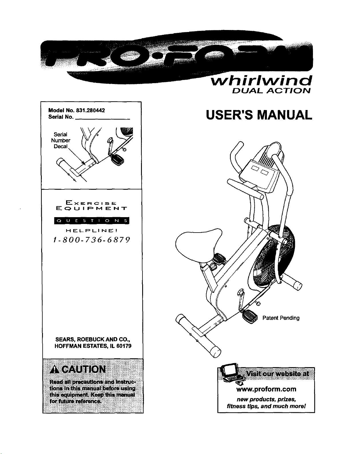
Model No, 831.280442
Serial No.
Serial
Number
Decal
EX EE R C I _. E
E(_UIPM ENT
HELPLINE!
1-800-736-6879
SEARS, ROEBUCK AND CO.,
HOFFMAN ESTATES, IL 60179
irlwind
DUAL ACTION
USER'S MANUAL
Patent Pending
www.proform.com
new products, prizes,
fitness tips, and much more!
DUAL ACTION
TABLE OF CONTENTS
IMPORTANT PRECAUTIONS ............................................................. 3
BEFORE YOU BEGIN ................................................................... 4
ASSEMBLY ........................................................................... 5
HOW TO OPERATE THE EXERCISE CYCLE ................................................. 9
MAINTENANCE AND TROUBLESHOOTING ................................................. 11
EXERCISE GUIDELINES ................................................................ 12
PART LIST ........................................................................... 14
EXPLODED DRAWING ................................................................. 15
HOW TO ORDER REPLACEMENT PARTS ........................................... BackCover
FULL 90 DAY WARRANTY ....................................................... BackCover
2

3
BEFORE YOU BEGIN
Congratulationsfor selectingthe new PROFORM®
WHIRLWIND exercise cycle. Cycling isone of the
most effectiveexercises for increasing cardiovascular
fitness, buildingendurance, and toning the entire
body. The PROFORM ®WHIRLWIND offers an array
of features designed to let you enjoy this healthful
exercise in the comfort and privacy of your home.
For your benefit, read this manual carefully before
you use the exercise cycle. Ifyou have questions
after readingthis manual, please call ourtoll-free
HELPLINE at 1-800-736-6879, Monday through
Saturday, 7 a.m. until7 p.m. Central Time (excluding
holidays).To help usassistyou, please mentionthe
productmodelnumberwhen calling.The modelnum-
ber is831.280442. The serial number can be found
on a decal attached tothe exercise cycle(see the
frontcover of this manual).
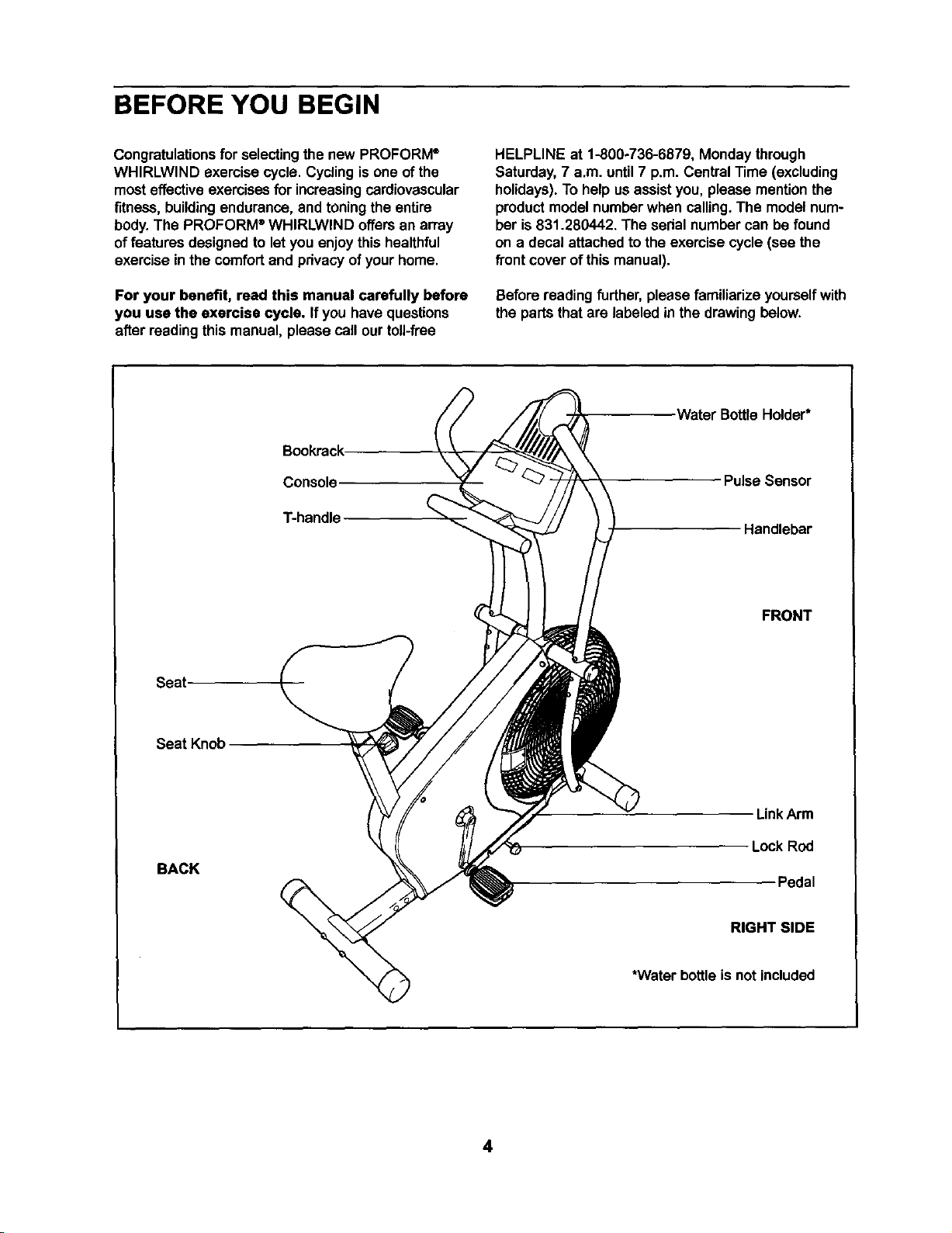
Beforereadingfurther,please familiarize yourselfwith
the parts that are labeled in the drawingbelow.
Bookrack
Console
T-handle
Seat
Seat Knob
BACK
Water BottleHolder*
Pulse Sensor
Handlebar
FRONT
LinkArm
Lock Rod
Pedal
RIGHT SIDE
*Water bottle is not included
4
ASSEMBLY
Assembly requires two persons. Placeall partsofthe exemise cyclein a clearedarea and remove the packing
materials. Do not dispose ofthe packingmatedals untilassembly is completed.
Assembly can be completed using the included tools; however, a rubber mallet (_ I is also
recommended.
t_J
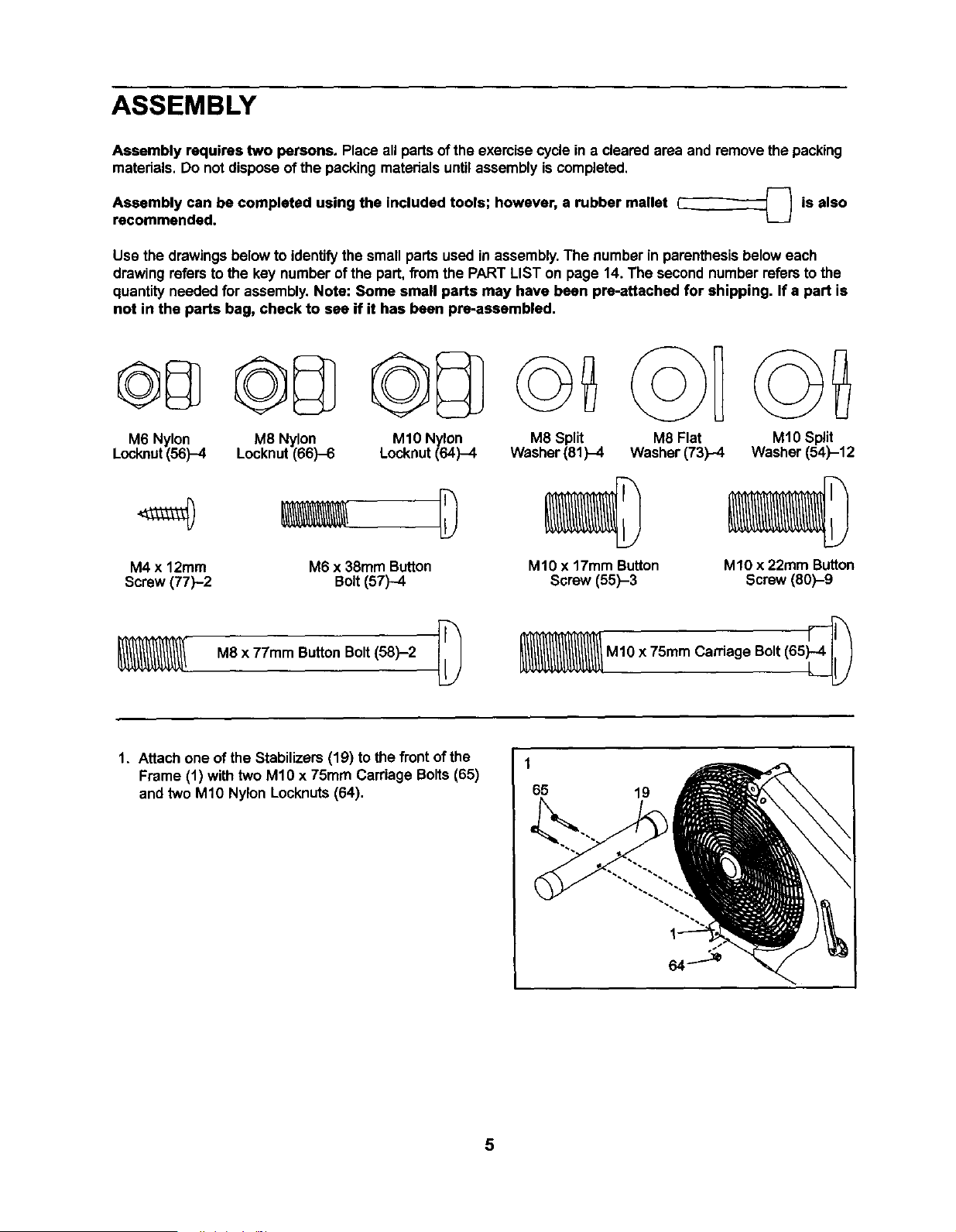
Usa the drawingsbelowto identifythe small partsused in assembly.The numberin parenthesisbelow each
drawingrefers tothe key number ofthe part,fromthe PART LIST on page 14. The secondnumber refersto the
quantityneeded for assembly.Note: Some small parts may have been prs-attached for shipping. If a part is
not in the parts bag, check to see if it has been pre-assembled.
M6 Nylon
Locknut(56)-4
M8 Nylon
Locknut(66)-6
M10 Nylon
Locknut (64)-4
M4 x 12ram M6 x 38mm Button
Screw (77)-2 Bolt(57)-4
M8 x 77mm ButtonBolt(58)-2 [_
M8 Split M8 Flat
Washer(81)-4 Washer (73)-4
M10 x 17mm Button
Screw (55)-3
M10 Split
Washer (54)-12
M10 x 22ram Button
Screw (60)-9
M1Ox 75mm Carriage Bolt(65_
1. Attach one of the Stabilizers (19) tothe front of the
Frame (t) with two M1Ox 75mm Carriage Bolts(65)
and two M10 Nylon Locknuts(64).
1
65
19
5
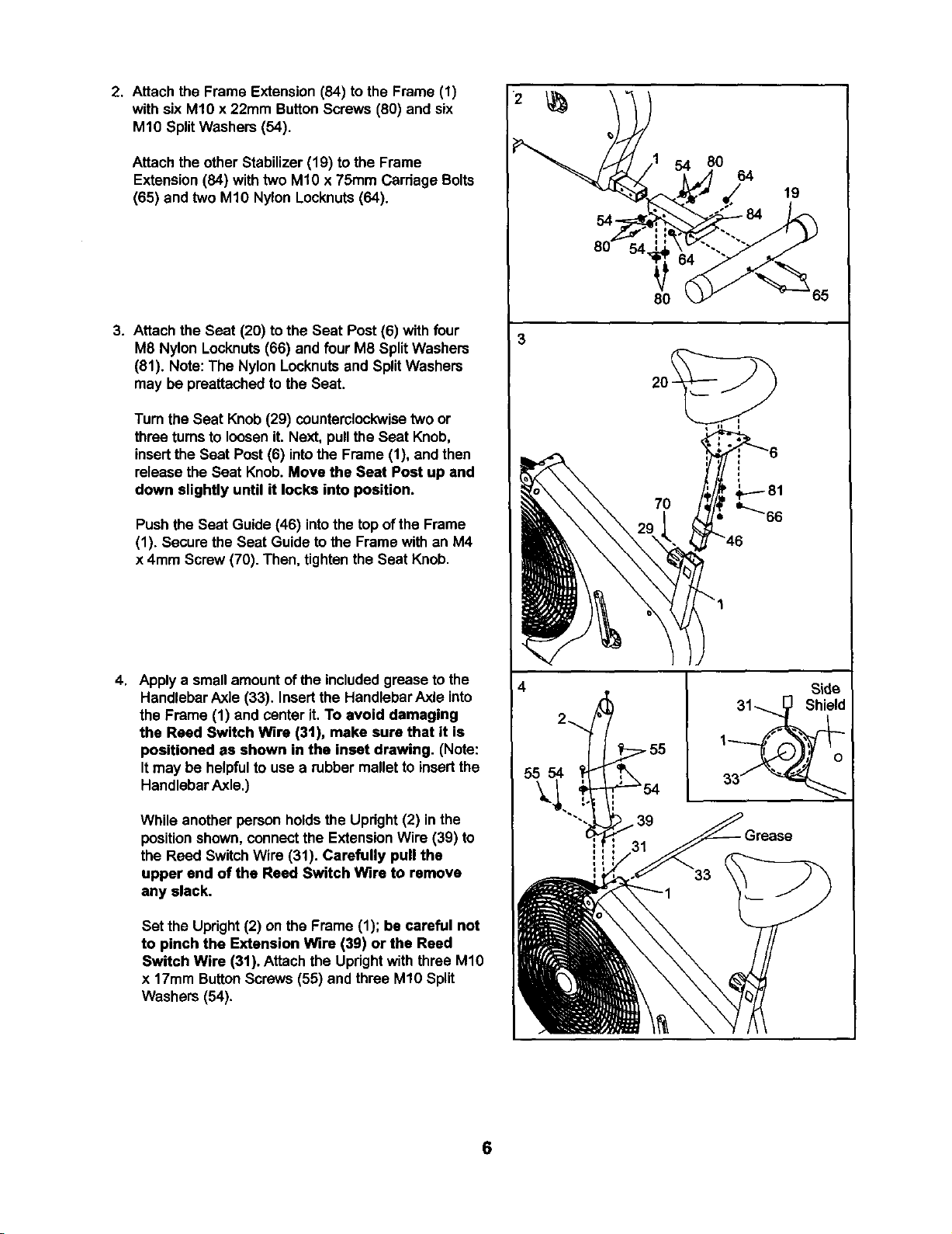
2. Attach the Frame Extension(84) tothe Frame (1)
with six M10 x 22mm ButtonScrews (80) and six
M10 SplitWashers (54).
Attach the other Stabilizer (19) to the Frame
Extension(84) withtwo M10 x 75mm Carriage Bolts
(65) and two M1ONylon Locknuts(64).
3. Attachthe Seat (20) to the Seat Post (6) with four
M8 Nylon Locknuts(66) and four M8 SplitWashers
(81). Note: The Nylon Locknutsand SplitWashers
may be preattached to the Seat.
Turn the Seat Knob (29) counterclockwisetwo or
three turnsto loosen it. Next, pullthe Seat Knob,
insertthe Seat Post (6) intothe Frame (1), and then
release the Seat Knob.Move the Seat Post up and
down slightly until it locks into position.
Push the Seat Guide (46) intothe top of the Frame
(1). Secure the Seat Guide to the Frame with an M4
x 4ram Screw(70). Then, tightenthe Seat Knob.
4. Apply a small amountofthe includedgrease to the
Handlebar Axle (33). Insertthe HandlebarAxle into
the Frame (1) and center it. To avoid damaging
the Reed Switch Wire (3t), make sure that it is
positioned as shown in the inset drawing. (Note:
Itmay be helpfulto use a rubber mallet to insertthe
HandlebarAxle.)
While another person holdsthe Upright(2) in the
positionshown, connectthe ExtensionWire (39) to
the Reed Switch Wire (31). Carefully pull the
upper and of the Reed Switch Wire to remove
any slack.
Set the Upright(2) on the Frame (1); be careful not
to pinch the Extension Wire (39) or the Reed
Switch Wire (31). Attach the Updghtwith three M10
x 17mm ButtonScrews(55) and three M10 Split
Washers (54).
3
55 54
54 80
64
80
7O
19
Side
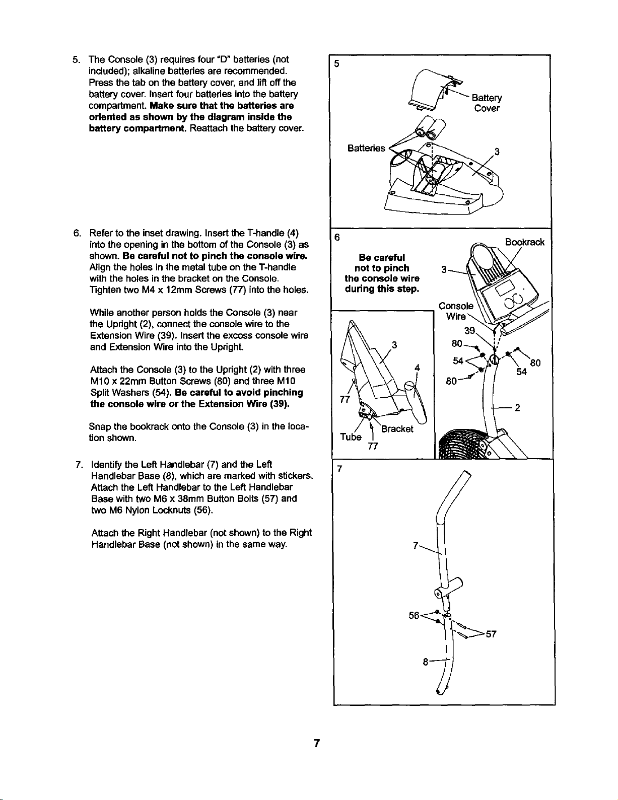
5. The Console (3) requiresfour "D"batteries (not
included); alkaline batteriesare recommended.
Press the tab on the batterycover,and liftoffthe
batterycover. Insert four batteriesintothe battery
compartment.Make sure that the batteries are
oriented as shown by the diagram inside the
battery compartment. Reattach the batterycover.
6. Refer to the inset drawing. Insertthe T-handle (4)
intothe opening inthe bottomof the Console (3) as
shown. Be careful not to pinch the console wire.
Alignthe holesin the metaltube on the T-handle
with the holesin the bracketon the Console.
"13ghtentwo M4 x 12mm Screws(77) intothe holes.
While another personholds the Console (3) near
the Updght (2), connect the console wire to the
ExtensionWire (39). Insert the excess consolewire
and ExtensionWire intothe Upright.
Attach the Console (3) to the Upright (2) withthree
M10 x 22ram ButtonScrews (80) and three M10
SplitWashers (54). Be careful to avoid pinching
the console wire or the Extension Wire (3g).
Snap the bookrack ontothe Console (3) in the loca-
tionshown.
7. Identifythe Left Handlebar (7) and the Left
Handlebar Base (8), whichare marked with stickers.
Attach the Left Handlebar to the Left Handlebar
Basewith two M6 x 38mm Button Bolts(57) and
two M6 Nylon Locknuts(56).
Attach the Right Handlebar (not shown)to the Right
Handlebar Base (not shown)in the same way.
Batteries <
3
Be careful
not to pinch
the console wire
during this step.
3_
Consok
Sookrack
77
7
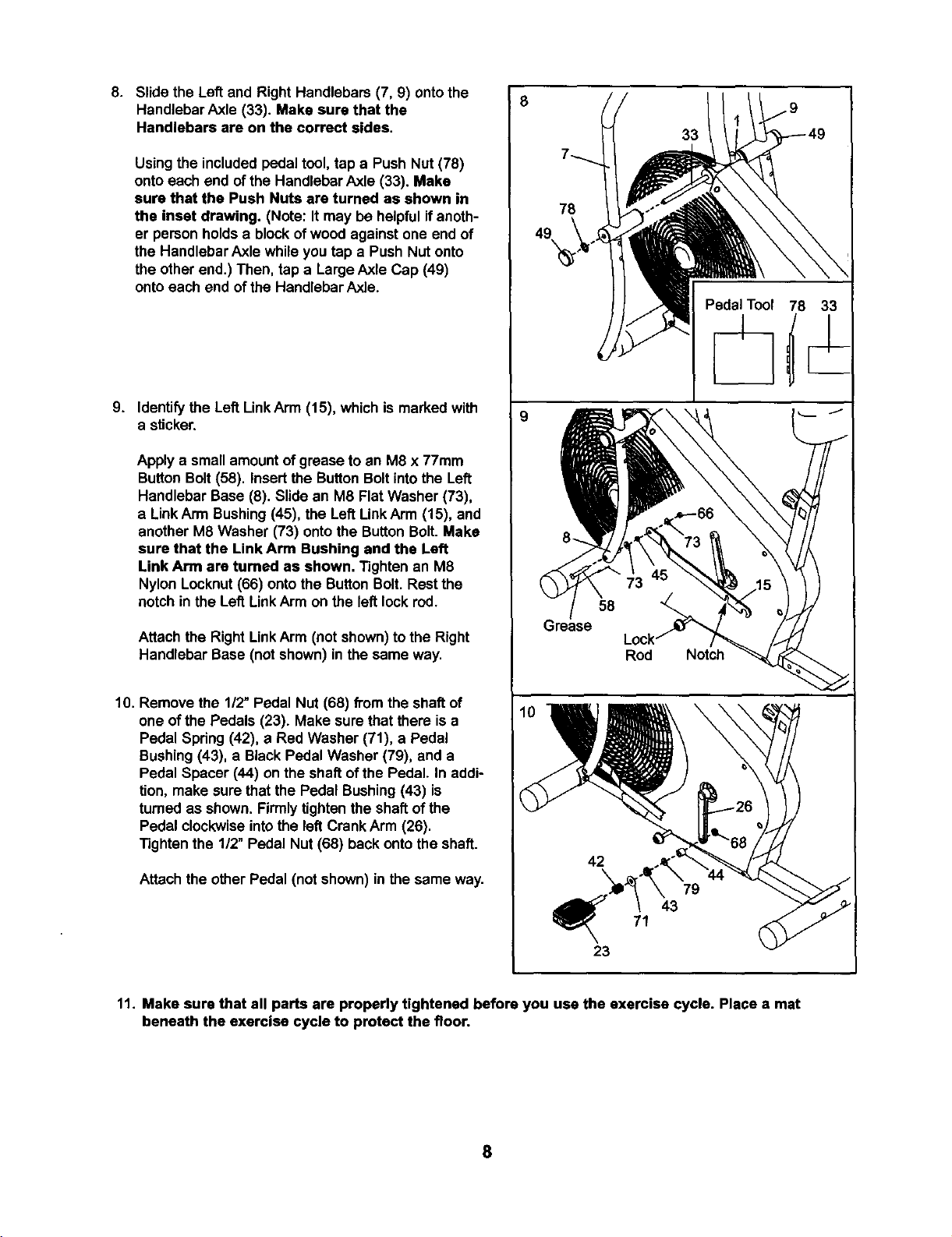
8. Slide the Left and Right Handlebars (7, 9) onto the
Handlebar Axle (33). Make sure that the
Handlebars are on the correct sides.
Using the included pedaltool, tap a Push Nut (78)
ontoeach end of the Handlebar Axle (33). Make
sure that the Push Nuts are turned as shown in
the inset drawing. (Note: It may be helpfulif anoth-
er personholds a blockof wood againstone end of
the Handlebar Axle while you tap a Push Nut onto
the other end.) Then, tap a LargeAxle Cap (49)
onto each end ofthe HandlebarAxle.
9. Identify the Left LinkArm (15), whichis marked with
a sticker.
Apply a small amountof grease to an M8 x 77mm
Button Bolt(58). insertthe ButtonBoltintothe Left
Handlebar Base (8). Slide an M8 Flat Washer (73),
a LinkArm Bushing(45), the Left LinkArm (15), and
another M8 Washer (73) onto the ButtonBolt. Make
sure that the Link Arm Bushing and the Left
Link Arm are tumed as shown. Tightenan M8
Nylon Locknut(66) ontothe ButtonBolt. Rest the
notch inthe Left LinkArm on the left lockrod.
Attach the Right LinkArm (not shown)tothe Right
Handlebar Base (not shown) inthe same way.
10. Remove the 112"Pedal Nut (68) from the shaft of
one ofthe Pedals (23). Make sure thatthere is a
Pedal Spdng (42), a Red Washer (71), a Pedal
Bushing(43), a Black Pedal Washer (79), and a
Pedal Spacer (44) on the shaft ofthe Pedal. In addi-
tion, make sure that the Pedal Bushing (43) is
turned as shown. Firmlytighten the shaftof the
Pedal clockwiseintothe left Crank Arm (28).
Tighten the 1/2" Pedal Nut (68) back ontothe shaft.
Attach the other Pedal (not shown) inthe same way.
8
9
78
8.
58
;raase
23
33
Rod Notch
71
79
43
11. Make sure that all parts are properly tightened before you use the exercise cycle. Place a mat
beneath the exercise cycle to protect the floor.
8
HOW TO OPERATE THE EXERCISE CYCLE
HANDLEBAR OPERATION
The handlebars can be used in eitherthe dual-action
mode,for bothupper-bodyand lower-bodyexercise,
or the stationarymode, for pedaling exercise only.
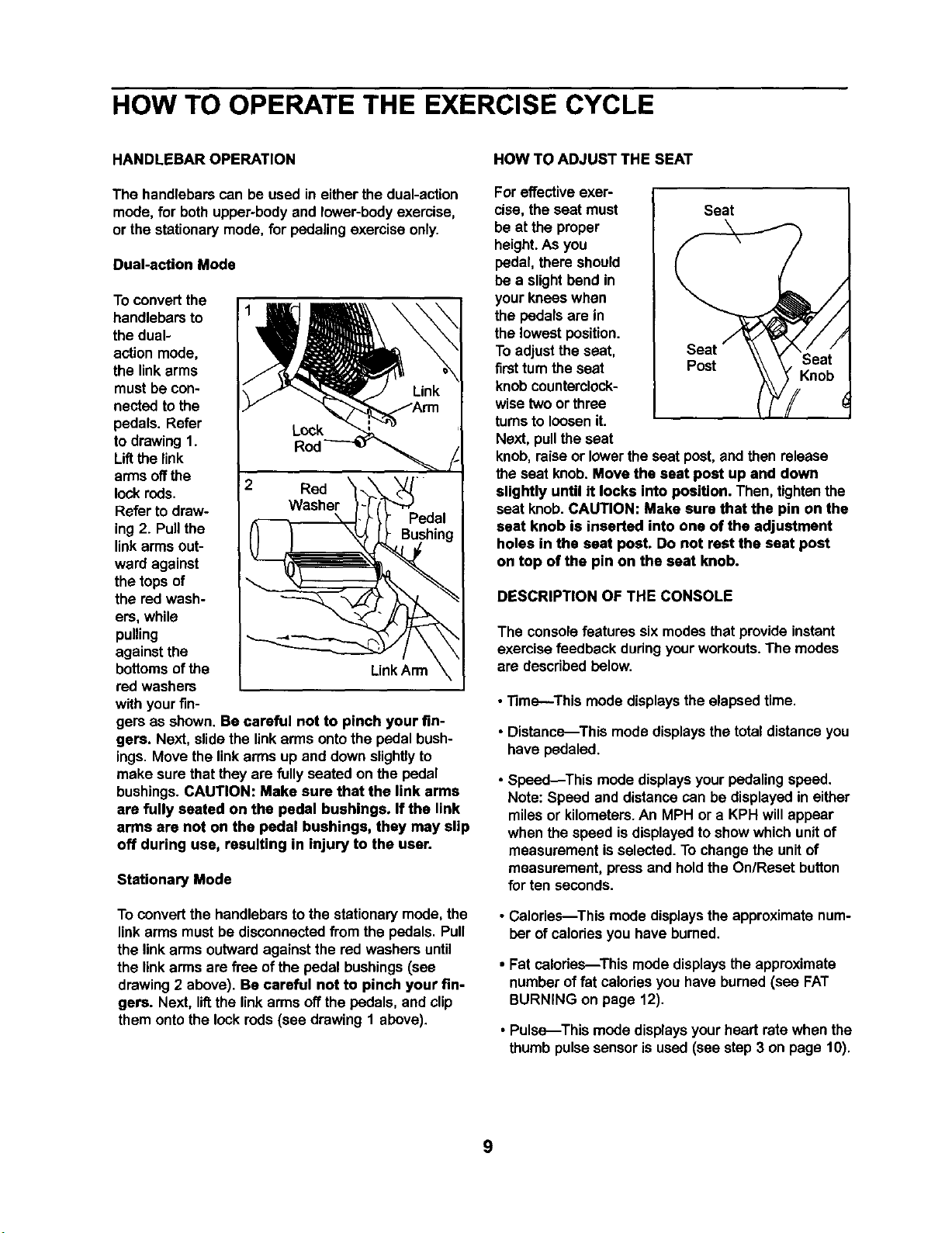
Dual-action Mode
To convertthe
handlebarsto
the dual-
actionmode,
the link arms
must be con-
nected to the
pedals. Refer
to drawing1.
Liftthe link
arms offthe
lock rods.
Refer todraw-
ing2. Pullthe
linkarmsout-
ward against
the tops of
the red wash-
ers, while
pulling
againstthe
bottomsofthe
red washers
with yourfin-
Rod
2 Red
_--t l _'_edal
Link Arm
\
gem as shown. Be careful not to pinch your fin-
gers. Next, slidethe linkarms ontothe pedal bush-
ings. Move the linkarms up and downslightlyto
make sure that they are fullyseated on the pedal
bushings.CAUTION: Make sure that the link arms
are fully seated on the pedal bushings, If the link
arms are not on the pedal bushings, they may slip
off during use, resulting in injury to the user.
Stationary Mode
To convertthe handlebars to the stationarymode, the
linkarms mustbe disconnectedfrom the pedals. Pull
the linkarms outwardagainst the red washers until
the linkarmsare free of the pedal bushings(see
drawing2 above). Be careful not to pinch your fin-
gers. Next, lif_the linkarms offthe pedals, and clip
them ontothe lock rods(see drawing1 above).
HOW TO ADJUST THE SEAT
For effectiveexer-
cise, the seat must Seat
be at the proper
height.As you
pedal, there should
be a slightbend in
your knees when
the pedals are in
the lowest position.
To adjustthe seat,
firstturnthe seat Post
knobcounterclock-
wisetwo or three
turnsto loosen it.
Next, pullthe seat
knob,raise or lowerthe seat post,and then release
the seat knob. Move the seat post up and down
slightly until it locks into position. Then, tightenthe
seat knob. CAUTION: Make sure that the pin on the
seat knob is inserted into one of the adjustment
holes in the seat post. Do not rest the seat post
on top of the pin on the seat knob.
Knob
DESCRIPTION OF THE CONSOLE
The consolefeatures six modesthat provideinstant
exercise feedback dudngyourworkouts.The modes
are describedbelow.
• Time--This mode displays the elapsed time.
• Distance--This mode displays the total distanceyou
have pedaled.
• Speed_This mode displaysyourpedaling speed.
Note: Speed and distance can be displayedin either
miles or kilometers.An MPH or a KPH willappear
when the speed isdisplayedtoshow which unitof
measurement is selected.To change the unitof
measurement, press and hold the On/Reset button
for ten seconds.
• Calories--This mode displays the approximatenum-
ber of calodesyou have bumed.
• Fat calories---This mode displays the approximate
number of fat calodes you have burned (see FAT
BURNING on page 12).
• Pulse--This mode displaysyour heart rate when the
thumbpulse sensoris used (see step 3 on page 10).
9
BATTERY INSTALLATION To resetthe displaysat any time, press the
On/Reset button.
The console requiresfour "D"batteries. To installbat-
teries, refer to assembly step 5 on page 7.
HOW TO OPERATE THE CONSOLE
Note: Ifthere isa piece of clear plasticon the face of
the console, remove it beforeoperatingthe console.
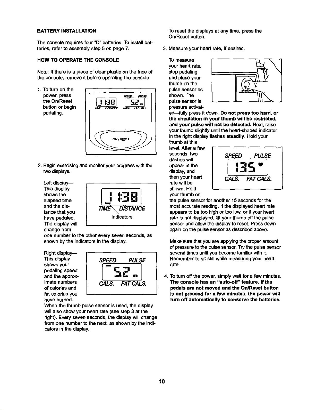
1. To turnon the
power, press
the On/Reset
button or begin
pedaling.
2. Beginexercisingand monitoryourprogresswiththe
two displays.
Left display--
This display
shows the
elapsed time
and the dis-
tance that you
have pedaled.
The displaywill
change from
TIME_ DISTANCE
Indicators
one number tothe other every seven seconds, as
shownby the indicators in the display.
Rightdisplay--
This display SPEED PULSE
showsyour [ " 1
pedalingspeed _ "_--|
and the approx- _I,C' up,
imate numbers CALS. FAT CALS.
ofcalodes and
fat celodes you
have burned.
When the thumb pulsesensor is used,the display
willalso show your heart rate (see step 3 at the
right). Everyseven seconds, the displaywillchange
from one number tothe next, as shownbythe indi-
cators in the display.
3. Measure yourheart rate, if desired.
To measure
yourhead rate,
stop pedaling
and place your
thumb on the
pulse sensor as
shown.The
pulsesensor is
pressureactivat-
ed---fullypressit down. Do not press too hard, or
the circulation in your thumb will be restricted,
and your pulse will not be detected. Next, raise
yourthumb slightlyuntilthe heart-shapedindicator
in the rightdisplayflashes steadily. Hold your
thumbat this
level.After a few
seconds,two SPEED PULSE
dashes will { 1
appear inthe I "JI __. U
display,and I _JI --|
thenyour heart OALS. FAT CALS.
ratewillbe
shown. Hold
yourthumb on
the pulsesensorfor another 15 secondsfor the
mostaccurate reading. Ifthe displayedheart rate
appearsto be too highor too low,or ifyourheart
rateis not displayed,liftyourthumb offthe pulse
sensorand allowthe displayto reset. Pressdown
againon the pulse sensoras describedabove.
Make surethatyou are applyingthe properamount
of pressure to the pulse sensor.Trythe pulsesensor
severaltimes untilyou becomefamiliar withit.
Remember to sitstillwhilemeasuringyourheart
rate.
4. Toturn off the power, simplywait for a few minutes.
The console has an "auto-off' feature. If the
pedals are not moved and the On/Reset button
is not pressed for a few minutes, the power will
turn off automatically to conserve the batteries.
10
MAINTENANCE AND TROUBLESHOOTING
Inspect and tightenall partsof the exercise cycleregu-
larly.To clean the exercise cycle, use a damp cloth
and milddetergent. Never use abrasivesor solvents;
keep liquidaway from the console.
CONSOLETROUBLESHOOTING
Ifthe consoledoes notfunction properly,the batteries
shouldbe replaced. See assembly step 5 on page 7
for battery installationinstructions.
ADJUSTING THE BELT
The exercisecyclefeatures a precisionbeltthat must
be kept properlyadjusted.Ifthe belt istoo tight,the
bearingsmay be damaged; if the belt istoo loose,the
fan may be damaged. Ifthe belt causesexcessive
noiseor slipsas you pedal,followthe steps below.
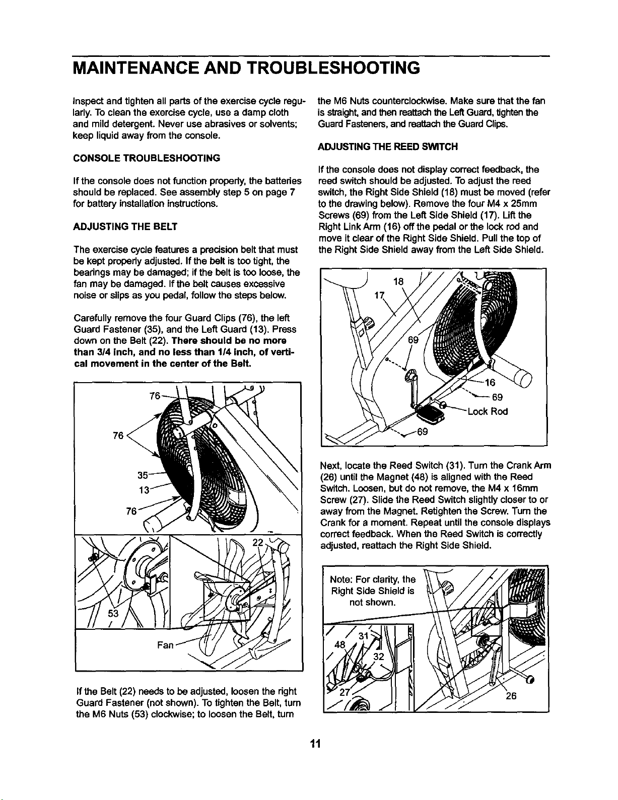
Carefully removethe fourGuard Clips(76), the left
Guard Fastener (35), and the LeftGuard (13). Press
down on the Belt (22). There should be no more
than 3/4 inch, and no less than 1/4 inch, of verti-
cal movement in the center of the Belt.
76 <
the M6 Nuts counterclockwise. Make surethat the fan
is straight,and thenreattachthe LeftGuard,tightenthe
GuardFasteners,and reattachthe GuardClips.
ADJUSTING THE REED SWITCH
If theconsole does not display correct feedback, the
reed switchshouldbe adjusted,To adjustthe reed
switch,the Right Side Shield (18) mustbe moved (refer
to the drawingbelow). Remove the four M4 x 25mm
Screws (69) from the Left Side Shield (17). Liftthe
Right LinkArm (16) offthe pedalor the lookred and
move itclear of the Right Side Shield, Pullthe top of
the Right Side Shield away from the LeftSide Shield.
18
69
Next, locate the Reed Switch (31). Turnthe Crank Arm
(26) until the Magnet (48) is alignedwith the Reed
Switch.Loosen,but do not remove,the M4 x 16mm
Screw (27). Slide the Reed Switchslightlycloserto or
away fromthe Magnet. Retightenthe Screw. Turnthe
Crankfor a moment. Repeat untilthe console displays
correctfeedback. When the Reed Switch iscorrectly
adjusted,reattach the Right Side Shield.
If the Belt(22) needs to be adjusted,loosenthe right
Guard Fastener (not shown). To tighten the Belt,turn
the M6 Nuts (53) clockwise; to loosen the Belt,turn
Note: For clarity, the
Right Side Shield is
not shown.
26
11
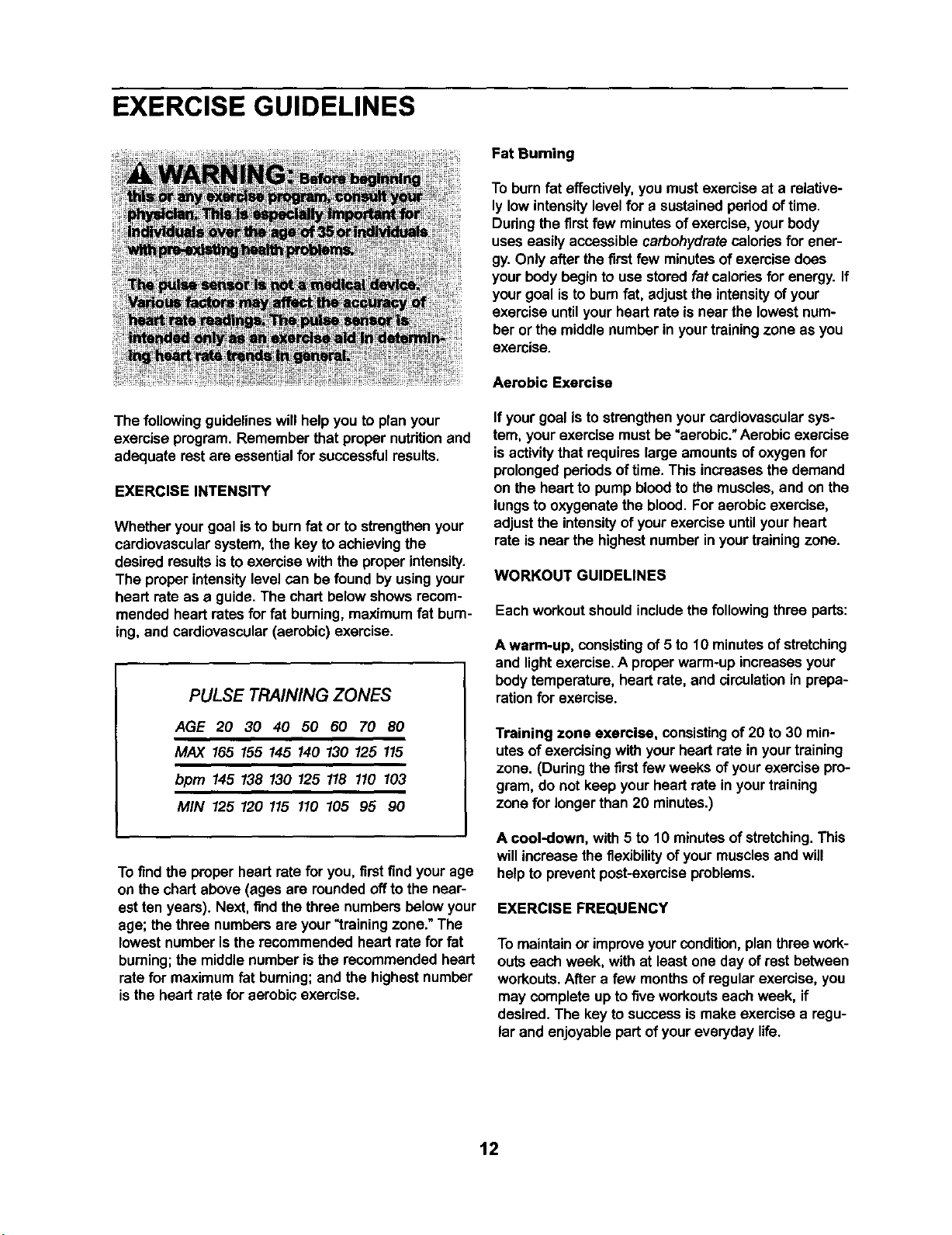
EXERCISE GUIDELINES
The following guidelineswill helpyou to planyour
exercise program. Remember that propernutdtionand
adequate rest are essentialfor successfulresults.
EXERCISE INTENSITY
Whether yourgoal is to burnfat or to strengthenyour
cardiovascularsystem,the key to achievingthe
desired resultsis to exercise with the properintensity.
The proper intensitylevelcan be found by usingyour
heart rate as a guide.The chart belowshows recom-
mended heart rates forfat burning, maximumfat bum-
ing, and cardiovascular(aerobic) exercise.
PULSE TRAINING ZONES
AGE 20 30 40 50 60 70 80
MAX 165 155 145 140 130 125 115
bpm 145 138 130 125 118 110 103
MIN 125 120 115 110 105 95 90
To findthe properheart ratefor you, firstfind yourage
on the chart above (ages are roundedoffto the near-
est ten years). Next, findthe three numbersbelow your
age; the three numbersare your_training zone."The
lowest number isthe recommendedheart ratefor fat
burning;the middle number isthe recommended heart
ratefor maximumfat burning;and the highestnumber
isthe heart ratefor aerobic exercise.
Fat Burning
To burnfat effectively,you mustexercise at a relative-
ly low intensitylevel for a sustained periodof time.
Duringthe firstfew minutesof exercise,yourbody
useseasily accessible carbohydratecaloriesfor ener-
gy. Only after the firstfew minutesof exercise does
yourbody beginto use stored fat caloriesfor energy. If
yourgoal isto bum fat, adjustthe intensityofyour
exercise untilyour heart rate is near the lowestnum-
ber or the middle number in yourtrainingzone as you
exercise.
Aerobic Exercise
If yourgoal is tostrengthenyour cardiovascularsys-
tem, yourexercise must be "aerobic."Aerobicexercise
isactivitythat requireslarge amountsofoxygen for
prolongedperiodsoftime. This increasesthe demand
on the heart to pump bloodto the muscles,and on the
lungsto oxygenate the blood. Foraerobic exercise,
adjustthe intensityof yourexercise untilyour heart
rate isnear the highest numberin yourtrainingzone.
WORKOUT GUIDELINES
Each workoutshouldincludethe followingthree parts:
A warm-up, consistingof 5 to 10 minutesofstretching
and lightexercise. A properwarm-up increasesyour
bodytemperature, heart rate, and circulationin prepa-
rationfor exercise.
Training zone exercise, consistingof 20 to 30 min-
utesof exercisingwith your heart rate in yourtraining
zone. (Duringthe firstfew weeks ofyour exercise pro-
gram, do not keep your heart rate in yourtraining
zone for longerthan 20 minutes.)
A cool-down, with 5 to 10 minutesofstretching.This
willincrease the flexibilityof yourmusclesand will
helpto preventpost-exerciseproblems.
EXERCISE FREQUENCY
To maintainor improveyourcondition,planthree work-
outs each week, with at least one day of restbetween
workouts.After a few monthsof regularexercise,you
may completeup to fiveworkoutseach week, if
desired.The key to successismake exercise a regu-
lar and enjoyable part ofyoureveryday life.
12
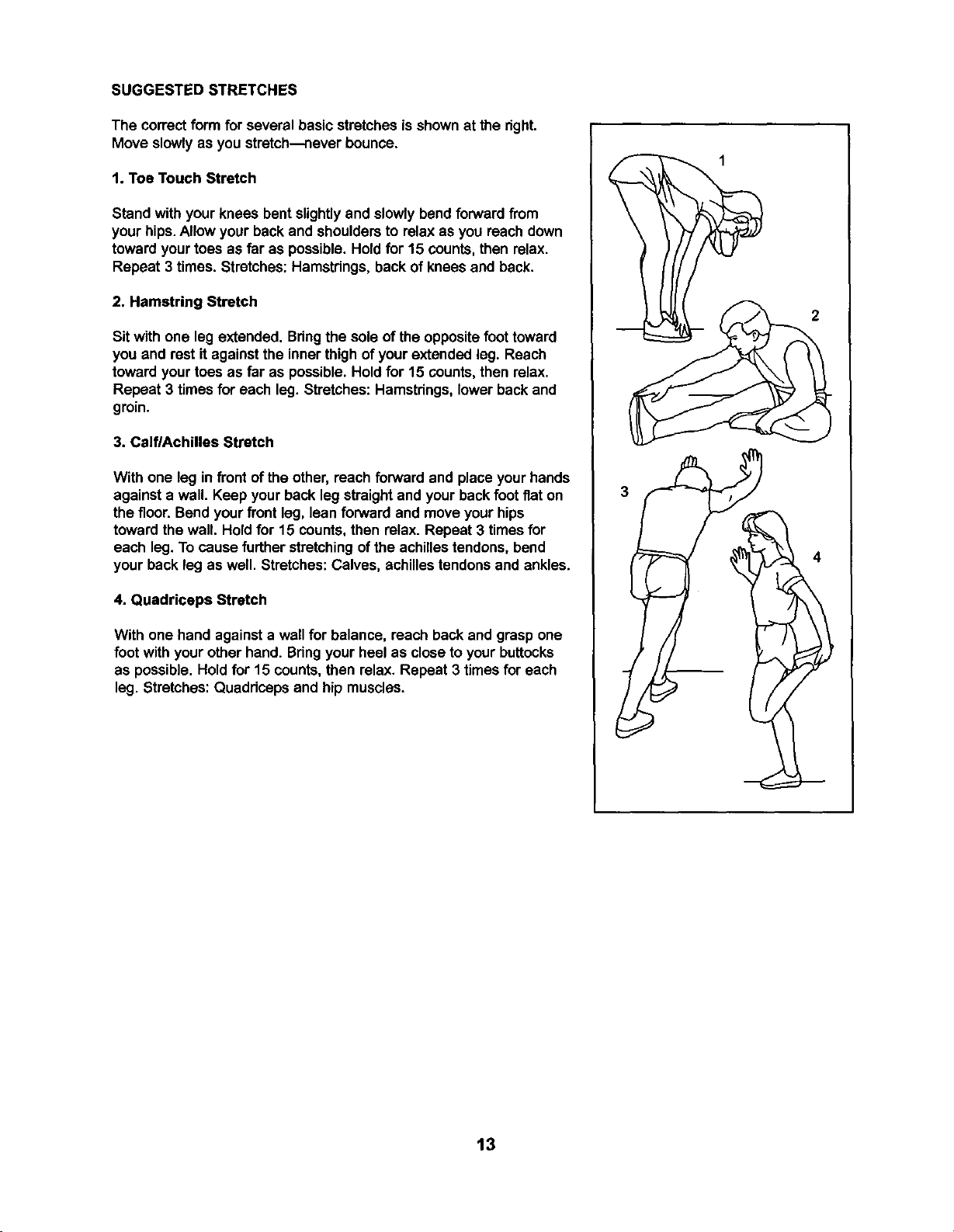
SUGGESTED STRETCHES
The correctform for several basic stretchesis shownat the right.
Move slowlyas you stretch---neverbounce.
1. Toe Touch Stretch
Stand with your knees bent slightlyand slowly bendforwardfrom
yourhips.Allow your backand shouldersto relax as you reach down
towardyourtoes as far as possible. Hold for 15 counts, then relax.
Repeat 3 times. Stretches:Hamstdngs, back of kneesand back.
2. Hamstring Stretch
Sit with one leg extended. Bdngthe sole of the oppositefoottoward
you and rest it againstthe inner thighof yourextended leg. Reach
toward yourtoes as far as possible.Hold for 15 counts, then relax.
Repeat 3 times for each leg. Stretches: Hamstdngs,lower backand
groin.
3. CelflAchilles Stretch
With one leg in front of the other, reach forward and place your hands
againsta wall. Keep your back leg straightand your backfoot flat on
the floor. Bendyour front leg, lean forward and moveyour hips
towardthe wall. Holdfor 15 counts,then relax. Repeat 3 timesfor
each leg.To cause further stretchingofthe achillestendons,bend
your backleg as well. Stretches:Calves, achillestendonsand ankles.
4. Quadriceps Stretch
With one hand againsta wall for balance, reach back and grasp one
foot withyour other hand. Bdngyour heel as close to yourbuttocks
as possible. Hold for 15 counts,then relax. Repeat 3 times for each
leg. Stretches: Quaddceps and hip muscles.
2
13
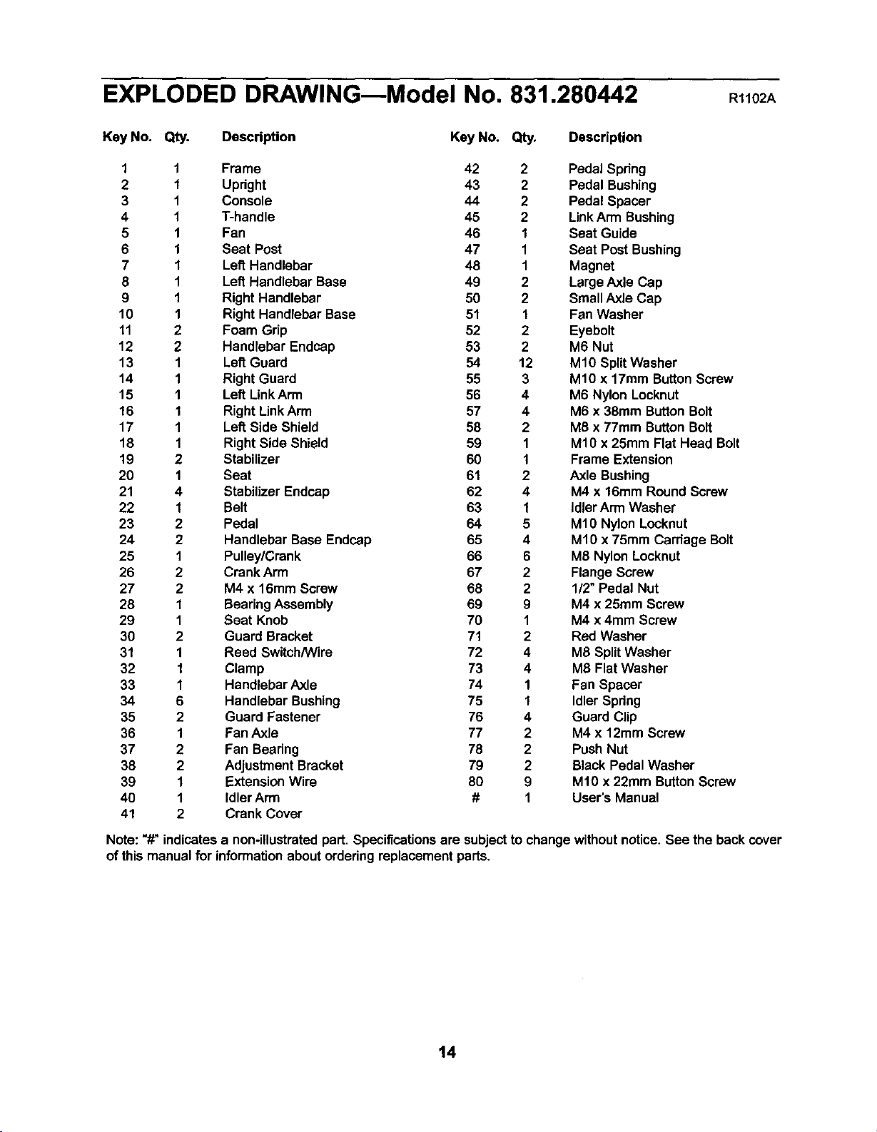
EXPLODED DRAWING--Model No. 831.280442 R1102A
Key No. Qty. Description Key No. Qty. Description
1 1 Frame 42 2 Pedal Spring
2 1 Upright 43 2 Pedal Bushing
3 1 Console 44 2 Pedal Spacer
4 1 T-handle 45 2 Link Arm Bushing
5 1 Fan 46 1 Seat Guide
6 1 Seat Post 47 1 Seat Post Bushing
7 1 Lett Handlebar 48 1 Magnet
8 1 Left Handlebar Base 49 2 Large Axle Cap
9 1 Right Handlebar 50 2 Small Axle Cap
10 1 Right Handlebar Base 51 1 Fan Washer
11 2 Foam Grip 52 2 Eyebolt
12 2 Handlebar Endcap 53 2 M6 Nut
13 1 Laf_Guard 54 12 M10 SplitWasher
14 1 Right Guard 55 3 M10 x 17mm ButtonScrew
15 1 Left LinkArm 56 4 M6 Nylon Locknut
16 1 Right LinkArm 57 4 M6 x 38ram ButtonBolt
17 1 Left Side Shield 58 2 M8 x 77mm ButtonBolt
18 1 Right Side Shield 59 1 M10 x 25ram Flat Head Bolt
19 2 Stabilizer 60 1 Frame Extension
20 1 Seat 61 2 Axle Bushing
21 4 Stabilizer Endcap 62 4 M4 x 16mm Round Screw
22 1 Belt 63 1 idler Arm Washer
23 2 Pedal 64 5 M10 Nylon Locknut
24 2 Handlebar Base Endcap 65 4 M1Ox 75ram Carriage Bolt
25 1 Pulley!Crank 66 6 M8 Nylon Locknut
26 2 Crank Arm 67 2 Flange Screw
27 2 M4 x 16mm Screw 68 2 1/2" Pedal Nut
28 1 BearingAssembly 69 9 M4 x 25mm Screw
29 1 Seat Knob 70 1 M4 x 4mm Screw
30 2 Guard Bracket 71 2 Red Washer
31 1 Reed Switch/Wire 72 4 M8 SplitWasher
32 1 Clamp 73 4 M8 Flat Washer
33 1 Handlebar Axle 74 1 Fan Spacer
34 6 Handlebar Bushing 75 1 IdlerSpdng
35 2 Guard Fastener 76 4 Guard Clip
36 1 Fan Axle 77 2 M4 x 12mm Screw
37 2 Fan Beadng 78 2 Push Nut
38 2 Adjustment Bracket 79 2 Black Pedal Washer
39 1 Extension Wire 80 9 Mt0 x 22ram ButtonScrew
40 1 Idler Arrn # 1 User's Manual
41 2 Crank Cover
Note: "#" indicatesa non-illustratedpart. Specifications are subjectto change withoutnotice. See the back cover
of this manualfor informationaboutorderingreplacement parts.
14
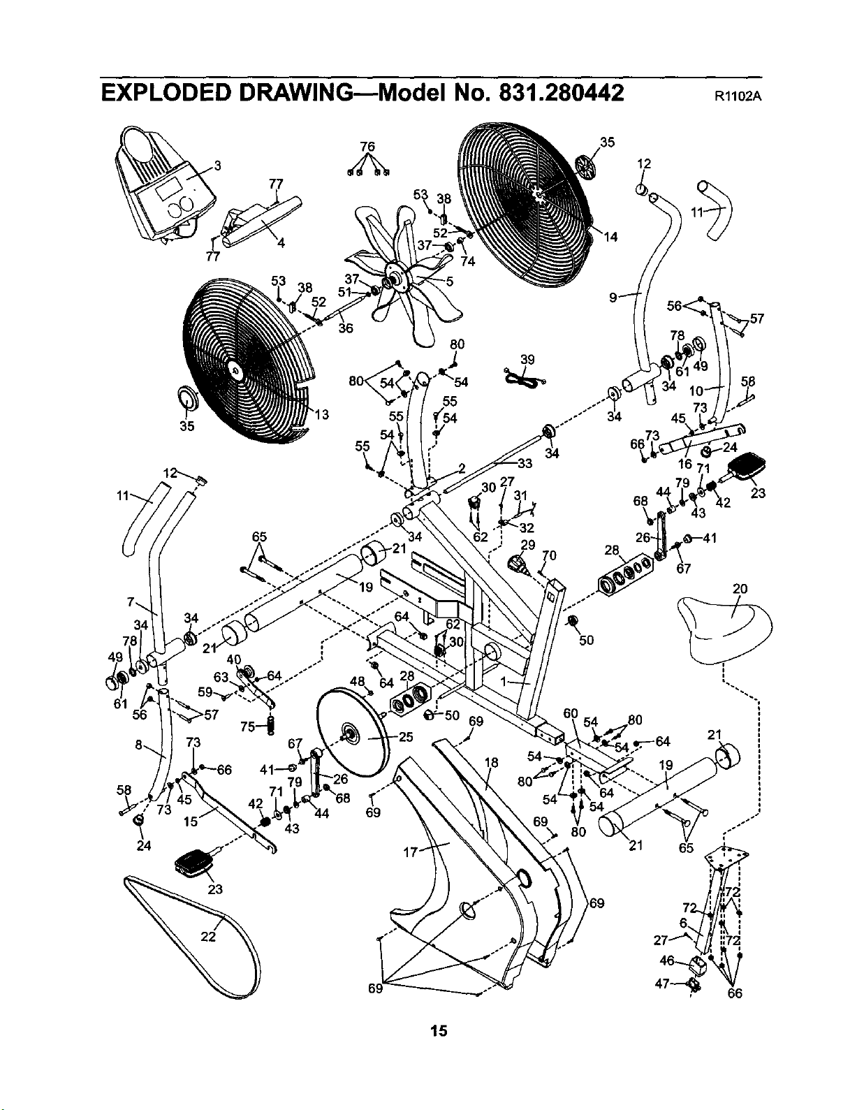
EXPLODED DRAWING--Model No. 831.280442
R1102A
38
76
53
12
56
35
36
55
8O
39
65 "32
29
69
.J
5O
68
28
80
23
43
67
20
21
73 69
43
65
::72
66
15
SEARS
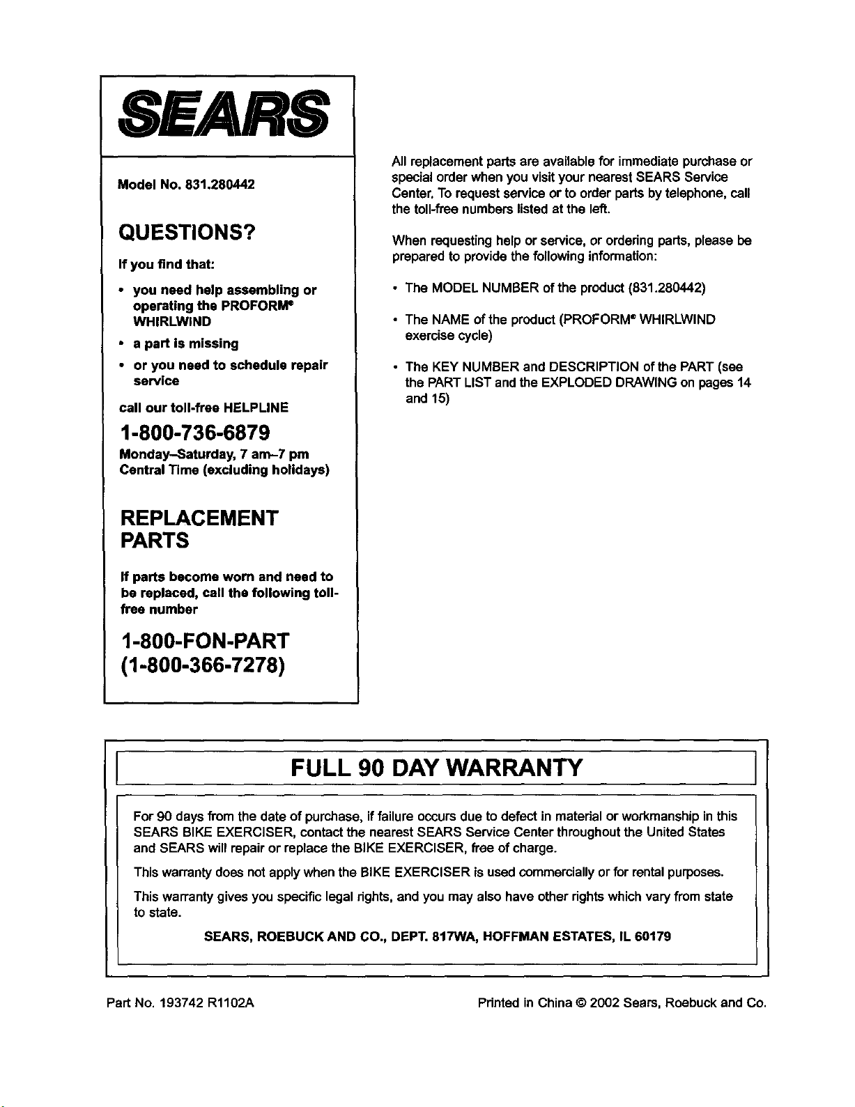
Model No. 831.280442
QUESTIONS?
If you find that:
• you need help assembling or
operating the PROFORI_
WHIRLWIND
• a part is missing
• or you need to schedule repair
service
call our toll-frae HELPLINE
1-800-736-6879
Monday-Saturday, 7 am-7 pm
Central Time (excluding holidays)
REPLACEMENT
PARTS
If parts become worn and need to
be replaced, call the following toll-
free number
1-800-FON-PART
(1-800-366-7278)
Allreplacement parts are available for immediatepurchaseor
specialorder when you visityour nearest SEARS Service
Center. To requestservice or to order parts bytelephone, call
the toll-freenumbers listedat the left.
When requestinghelpor service,or orderingparts, please be
prepared to providethe followinginformation:
• The MODEL NUMBER of the product (831.280442)
• The NAME ofthe product(PROFORM ®WHIRLWIND
exercise cycle)
• The KEY NUMBER and DESCRIPTION of the PART (see
the PARTLIST andthe EXPLODED DRAWING on pages 14
and 15)
FULL 90 DAY WARRANTY
For90 days fi'omthe date of purchase,if failureoccursdue to defect in material or workmanshipinthis
SEARS BIKE EXERCISER, contactthe nearest SEARS Service Centerthroughoutthe United States
and SEARS willrepair or replacethe BIKE EXERCISER, free of charge.
Thiswarrantydoes not applywhen the BIKE EXERCISER isused commerciallyor for rentalpurposes.
This warrantygives you specificlegalrights, and you may also have otherrights whichvaryfrom state
tostate.
SEARS, ROEBUCK AND CO., DEPT. 817WA, HOFFMAN ESTATES, IL 60179
Part No. 193742 R1102A Pdnted in China © 2002 Sears, Roebuck and Co.