
- 1 -
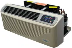
PACKAGED TERMINAL
AIR CONDITIONER/HEAT PUMP
INSTALLATION INSTRUCTIONS & OWNER'S MANUAL
EZ42/EZDR
ATTENTION INSTALLATION PROFESSIONAL
As a professional installer you have an obligation to know the product better than the customer. This includes all safety
precautions and related items.
Prior to actual installation, thoroughly familiarize yourself with this instruction manual. Pay special attention to all safety
warnings.
Often during installation or repair it is possible to place yourself in a position which is more hazardous than when the unit
is in operation.
Remember, it is your responsibility to install the product safely and to know it well enough to be able to instruct a customer
in its safe use.
Safety is a matter of common sense, a matter of thinking before acting. Most dealers have a list of specific good safety
practices, follow them.
The precautions listed in this Installation Manual are intended as supplemental to existing practices. However, if there is
a direct conflict between existing practices and the content of this manual, the precautions listed here take precedence.
- 2 -
CONTENTS
UNIT FEATURES ........................................................................ 3
INSTALLATION INSTRUCTIONS ......................................... 5
WIRING ........................................................................................ 9
OPERATING INSTRUCTIONS ............................................... 10
MAINTENANCE AND CLEANING ....................................... 12
NORMAL OPERATING SOUNDS AND CONDITION ............. 14
DIAGNOSTIC CODES ......................................................... 15
TROUBLE SHOOTING ........................................................ 16
IMPORTANT NOTES:
Before using this manual, check the serial plate for proper
model identification.
The installation and servicing of this equipment must be
performed by qualified, experienced technicians only.
Due to our policy of continual product improvement, the
right is reserved to change specifications and design
without notice.
IMPORTANT NOTE TO THE OWNER
This manual is to be used by qualified, professionally trained
HVAC technicians only. The manufacturer does not assume
any responsibility for property damage or personal injury for
improper service procedures or services performed by an
unqualified Person.
IMPORTANT NOTE TO THE SERVICER
Read this manual and familiarize yourself with the specific
items which must be adhered to before attempting to
service this unit. The precautions listed in this Installation
Manual are intended as supplemental to existing
practices. However, if there is a direct conflict between
existing practices and the content of this manual, the
precautions listed here take precedence.
RECOGNIZE THIS SYMBOL
AS A SAFETY PRECAUTION
WARNING
THE MANUFACTURER WILL NOT BE RESPONSIBLE FOR
ANY INJURY OR PROPERTY, DAMAGE ARISING FROM
IMPROPER SERVICE OR SERVICE PROCEDURES. IF YOU
INSTALL OR PERFORM SERVICE ON THIS UNIT, YOU
ASSUME RESPONSIBILITY FOR ANY PERSONAL INJURY
OR PROPERTY DAMAGE WHICH MAY RESULT, MANY
JURISDICTIONS REQUIRE A LICENSE TO INSTALL OR
SERVICE HEATING AND AIR CONDITIONING EQUIPMENT.
WARNING
HIGH VOLTAGE
DISCONNECT ALL POWER BEFORE SERVICING OR
INSTALLING THIS UNIT. MULTIPLE POWER SOURCES MAY
BE PRESENT, FAILURE TO DO SO MAY CAUSE PROPERTY
DAMAGE, PERSONAL INJURY OR DEATH.
- 3 -
UNIT FEATURES
This unit has many features which are different than
those found on conventional PTAC units. The servicer
must be familiar with these features in order to properly
handle the unit.
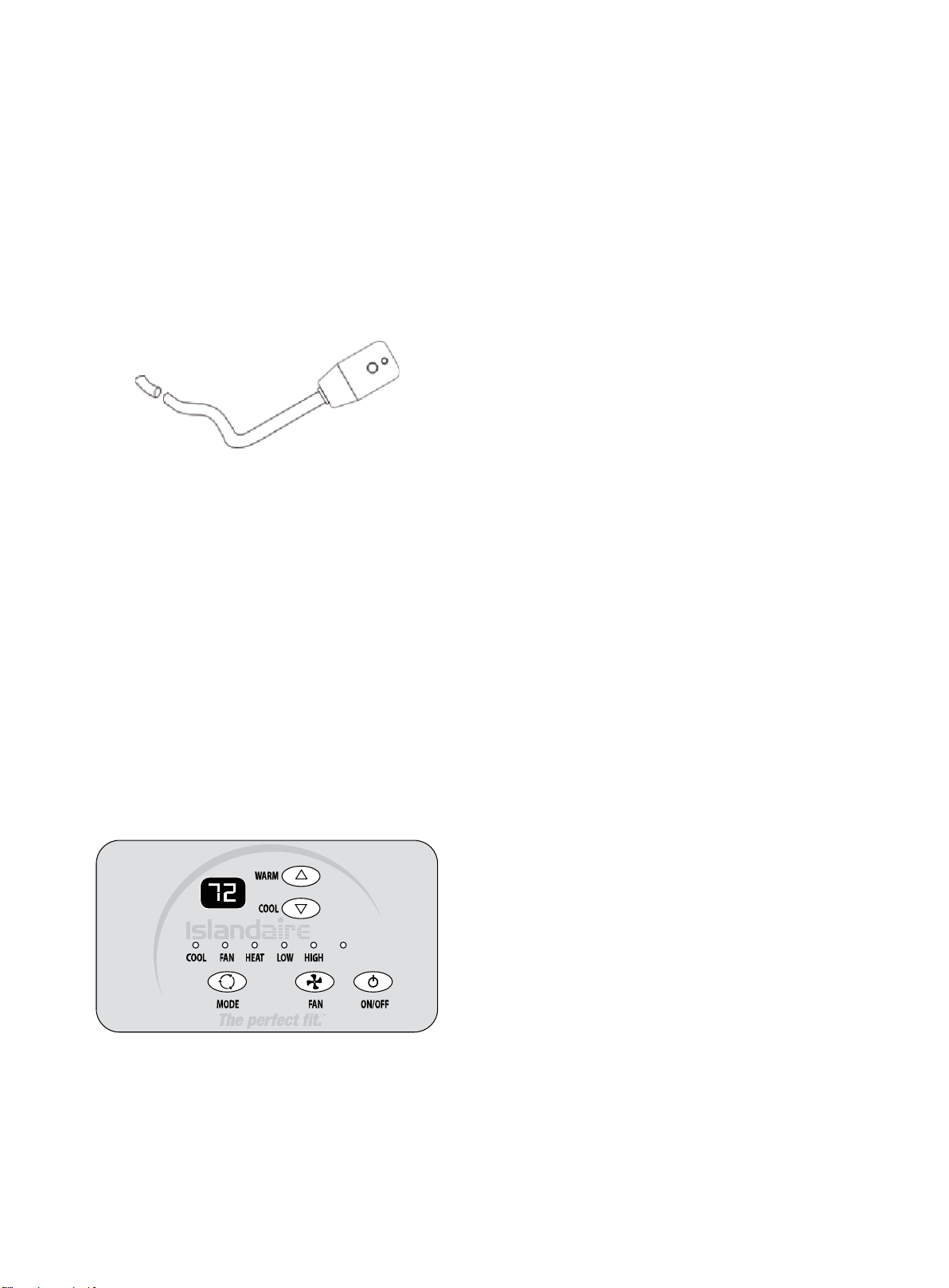
•
LCDI Cords - Underwriters Laboratories and the
National Electric Code (NEC) now require power
cords that sense current leakage and can open the
electrical circuit to the unit on units rated at 250 volts
or less. In the event that unit does not operate, check
the reset button located on or near the head of the
power cord as part of the normal troubleshooting
procedure.
LCDI power Cord
•
Automatic 3-minute compressor lockout - After
the compressor cycles off, it will not restart for three
minutes.
•
Random restart delay - To help eliminate power
surges after a power outage, the unit is equipped
with a two- to four-minute random restart delay
feature. Whenever the unit is plugged in with the
master switch turned on and the mode switch set in
the cool or heat mode, a random restart will occur. A
random restart condition can be avoided by setting
the mode switch in the fan only or off position before
applying power to the unit.
•
Indication LEDs - The touch pad has LEDs that
correspond to fan operation and to indicate unit
status. The LEDs next to the ON/OFF, FAN, COOL,
and HEAT selections indicate which operational
mode is active.
•
High Pressure Protection - The unit shuts off
automatically when the pressure in the system is over 638
psi, and within 10 minutes after the compressor turns off,
the unit will restart when the pressure falls back below 551
psi. This protection can effectively avoid bursting and
leakage of pipes, lessen system failures and prolong
service life.
•
Failure Tolerance - If the unit is in protection mode less
than 4 times in one hour, the accumulation times will reset
to avoid system failure. Only when the unit enters protection
mode more than 4 times in one hour, the system will fail to
restart automatically and need manual restarting.
•
Standard Physical Dimensions - The EZ42 and EZDR
series PTAC’s both have the same dimensions (42" wide x
16" high x 13-3/4" deep).
•
Weather Protected Electrical Components - Vital
electrical components are protected from the weather by
locating them on the indoor side of the weather barrier.
•
Highly Featured Microprocessor Controls -
Microprocessor controls are programmed to interface with
the temperature sensors to maximize comfort conditions for
the room occupant and provides many outstanding features.
Thermistors are used to sense small changes in
temperature to give excellent room control and allow the
microprocessor to monitor and react to changing conditions.
•
Automatic Emergency Heat on Heat Pump Units -
Automatically uses electric resistance heat if the heat pump
output is not sufficient to maintain selected room
temperature.
•
High-Temperature Heat Pump Operation
Protection - Automatically protects the compressor if the
heat pump is operated with high indoor coil
temperatures. Power to the outdoor fan and the
compressor are turned off if the indoor coil gets too hot
during heat pump operation to prevent damage to the
compressor.
AUTO
- 4 -
•
Permanently Lubricated Fan Motors - All units
have two fan motors for quiet operation and
maximum operating efficiency.
Motors are permanently lubricated to reduce
maintenance and totally enclosed to keep dirt and
water out of the motor windings.
•
Indoor Fan Speed Selections LOW/HIGH - Unit
may be operated in low fan speed or high fan speed.
•
Rotary Compressor - Smoother operation for quiet,
dependable service and high efficiency.
•
Indoor Coil Frost Control - Prevents indoor coil from
freezing. Frost can form on the indoor coil when the unit is
operated in cooling when outdoor temperature is low. The
unit automatically shuts the compressor off until the
indoor coil temperature warms to the point where
frosting will no longer occur, then restarts the
compressor.
WARNING
HIGH VOLTAGE
DISCONNECT ALL POWER BEFORE SERVICING OR
INSTALLING THIS UNIT. MULTIPLE POWER SOURCES MAY
BE PRESENT, FAILURE TO DO SO MAY CAUSE PROPERTY
DAMAGE, PERSONAL INJURY OR DEATH.
DR.PTAC INFORMATION
The Dr.PTAC system is an add on component to our
standard PTAC unit to provide conditioned make up
air into a space through the PTAC unit by providing
up to 55 CFM of outdoor air 24/7 by forced fan and
cycling dehumidifier compressor based on outdoor
relative humidity levels.
Dr.PTAC is a two-stage system: The primary unit is
responsible for control of Sensible Heat that is
introduced into the room via make up air temperature
and thermal load of the occupants. The secondary
unit is primarily a dehumidification unit that provides
up to 55 CFM of outside fresh air into the room. The
correction of the Sensible Temperature comes from
the main PTAC unit, which provides additional
dehumidification with temperature correction.
Overall unit efficiency over standard PTAC’s is
approximately 3% improvement. The compressor/de-
humidification process is controlled by a humidistat
(factory set at 50% RH), which is monitoring the
outdoor relative humidity level and is adjustable by a
qualified servicer. When the outdoor humidity level
raises above 50% RH, the compressor and
dehumidification process starts. Below 50% RH,
compressor operation and dehumidification is
stopped, however, fan operation continues to provide
up to 55 CFM of outdoor air into the space.
UNIT ACCESSORIES
This unit is designed for through-the-wall installation
in new or existing buildings. To complete the
installation of this PTAC, an insulated wall sleeve
and an outdoor grille (either the stamped aluminum
grille or the architectural grille) are required.
The chassis and the cabinet front are shipped in one
carton. Optional accessories to complete a particular
installation include the following:
OPTIONAL ACCESSORIES
Power Switch Kit
Wall Sleeve Kit
Key Lock Kit Drain Kit
Filter Kit
Hard Wire Kit
Wire Harness Kit
Architectural Grille Kit
Stamped Louver Kit
LCDI Power Cord
Wireless IR Antenna
Wireless IR Thermostat
Electric And Non Electric Sub Base Kit
NOTE: Consult sales literature for the appropriate
voltage and amperage selections, if applicable.
- 5 -
INSTALLATION INSTRUCTIONS
To ensure that the unit operates safely and efficiently, it must be installed, operated and maintained according to these
installation and operating instructions and all local codes and ordinances or, in their absence, with the latest edition of
the National Electric Code. The proper installation of this unit is described in the following sections. Following the steps in
the order presented should ensure proper installation.
WARNING
HIGH VOLTAGE
DISCONNECT ALL POWER BEFORE SERVICING OR
INSTALLING THIS UNIT. MULTIPLE POWER SOURCES MAY
BE PRESENT, FAILURE TO DO SO MAY CAUSE PROPERTY
DAMAGE, PERSONAL INJURY OR DEATH.
WALL SLEEVE ASSEMBLY (OPTIONAL ACCESSORY)
Welded Integrated Wall Sleeve
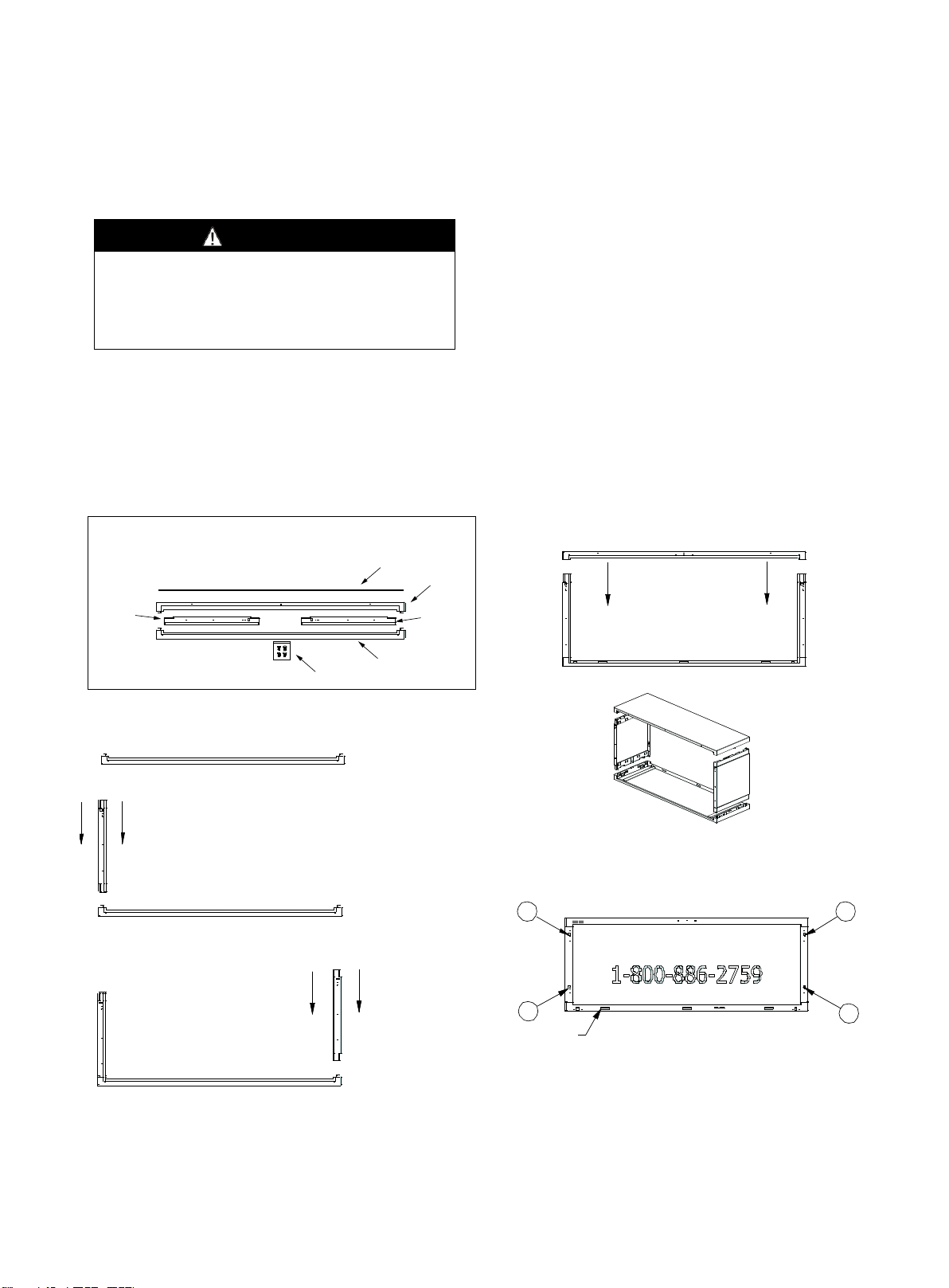
The wall sleeve features an aesthetically pleasing appearance and sturdy construction (refer to Fig 1.).
Customers can purchase the Wall Sleeve together with the unit. See wall sleeve assembly instructions below:
Fig 1
1
2
4
3
WEEP HOLES
REAR VIEW
WEATHER BOARD
TOP PANEL
LEFT SIDE
PANEL
PUSH PINS
BOTTOM PANEL
RIGHT SIDE
PANEL
PACKA
GE CONTEN TS
STEP 1. SET BOTTOM PANEL ON A
CLEAN FLAT AND LEVEL SURFACE.
STEP 2. LOCATE LEFT SIDE PANEL. ALIGN
PANEL IN THE LEFT BOTTOM PANEL SLOT.
FULLY INSERT LEFT PANEL INTO BOTTOM
PANEL UNTIL LOCKING TABS ENGAGE.
STEP 3. LOCATE RIGHT SIDE PANEL.
ALIGN PANEL IN THE RIGHT BOTTOM
PANEL SLOT. FULLY INSERT RIGHT
PANEL INTO BOTTOM PANEL UNTIL
LOCKING TABS ENGAGE.
STEP 4. LOCATE TOP PANEL
AND ALIGN WITH TOP OF RIGHT
AND LEFT SIDE PANELS. FULLY
INSERT TOP PANEL INTO RIGHT
AND LEFT PANELS UNTIL
LOCKING TABS ENGAGE.
STEP 5. (IF REQUIRED) LOCATE WEATHER BOARD AND ATTACH
TO THE INSIDE REAR OF THE ASSEMBLED SLEEVE WITH FOUR
(4) SUPPLIED PUSH PINS. REMOVE WEATHER BOARD PUSH
PINS AT TIME OF AIR CONDITIONER INSTALLATION.
- 6 -
SLEEVE INSTALLATION
Wall sleeve location
When making the wall opening, please observe the
following requirements:
A) The air inlet and outlet should be unblocked and the air
can be delivered to every corner of the room.
B) Install the unit in places that are away from heat source
or sources of flammable gases.
C) Do not install the unit in places that are subject to
excessive dust.
D) Do not install the unit in places were the operational
noise and exhausted air might disturb your neighbor.
E) There should be sufficient space around the unit to
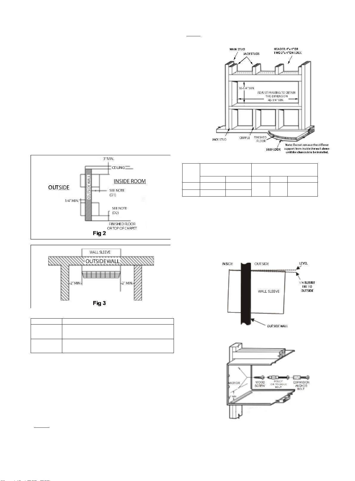
facilitate maintenance and repairs (refer to Figs 2 and 3).
Chart 1
Dimensions
Recommended installation clearance
D1
Projection of case into room - 1/2" minimum, up to1-3/4"
maximum without use of electrical sub-base.
Note: 2-3/8" minimum when sub-base is used.
D2
Height above finished floor or top of carpet:
1/2"minimum, 2" recommended without sub-base,
3" minimum with sub-base.
Preparation of the wall
The sleeve should be installed during construction and
lintels should be used to support the block above the wall
sleeve. The sleeve can not support the load of
bricks/blocks.
For existing construction, a wall opening must be
created; proper dimensions are necessary to avoid use of
fillers or additional framing. The sleeve is modular in
height and width (refer to Fig 4 and Chart 2).
Height:
Fits 2 courses concrete block
Fits 6 courses standard brick
Fits 5 courses jumbo brick
Width:
Fit approximately 3 stud spaces.
Chart 2
minimum finished
opening dimensions
sleeve dimensions
Height
width
height
width
depth
NO. 1 16-1/4"
42
-
1
/
2
"
16" 42"
13-3/4"
(16"/18"/24
")
NO. 2 16-1/4"
42
-
1
/
4
"
NOTE: NO.1 means using field supplied sleeve angles
NO.2 means not using field supplied sleeve angles
In order for condensate water to drain properly inside the
unit, the sleeve must be installed properly:
•
Level from right-to-left
•
A slight downward pitch from the indoor side to
the outdoor side as shown below (Fig 5)
•
Fasten the wall sleeve (Fig 6)
Fig 5. Proper Sleeve Tilt
Fig 6. Wall Sleeve Anchors
- 7 -
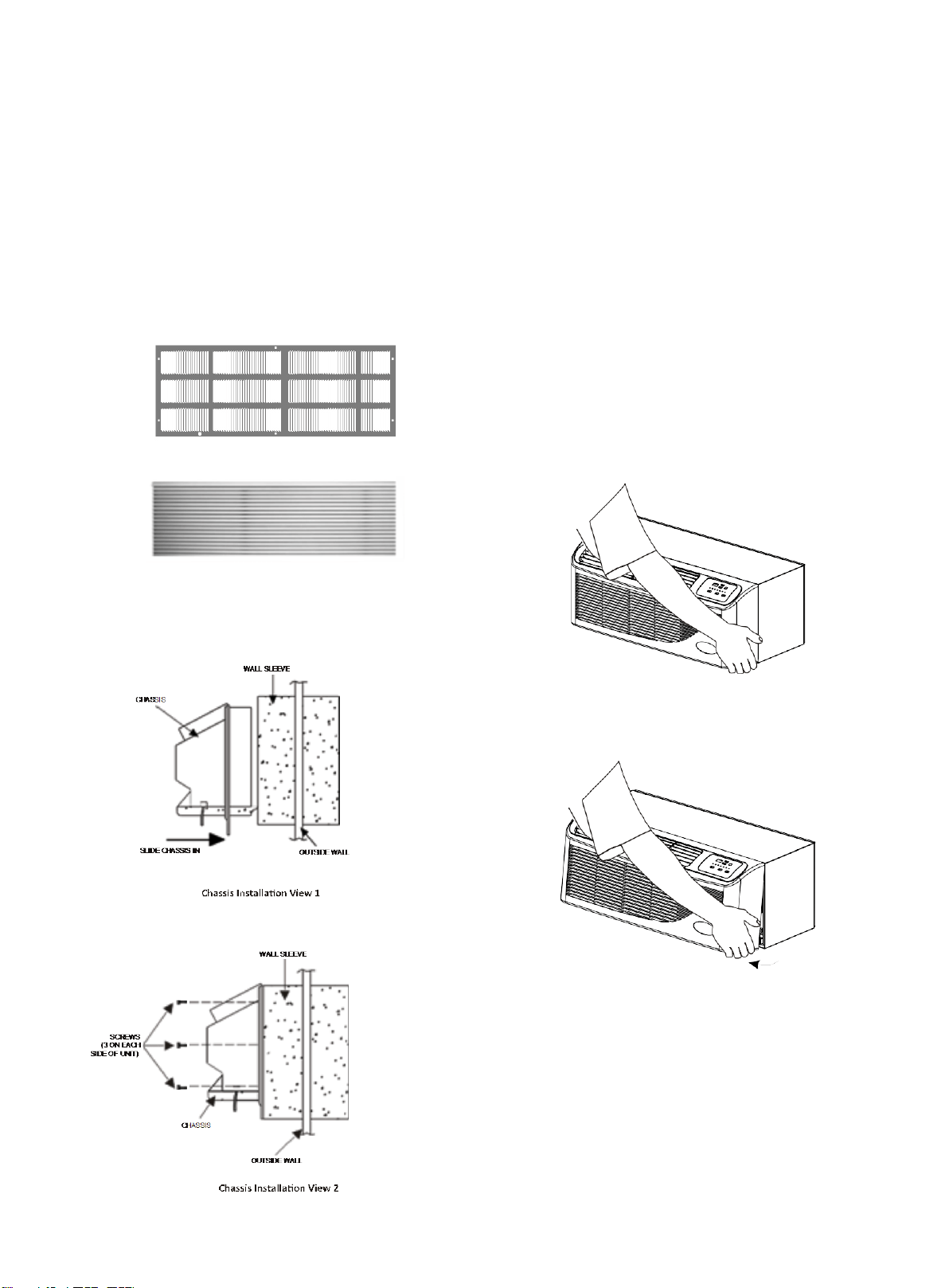
OUTDOOR GRILLE (OPTIONAL ACCESSORY)
An outside grille must be installed to direct air flow for
proper unit operation and also protect the outdoor coil. The
grille must be installed before installing the chassis.
When replacing an old chassis with an existing grille or
using a specialized grille in a new installation, please
check with Islandaire engineering to determine if the new
chassis should be used with the non-standard
specialized grille. An improper outdoor grille can decrease
cooling or heating capacity, increase energy usage and
shorten compressor life and possibly void the warranty.
Flush Stamped Louver
Architectural Louver
CHASSIS INSTALLATION
1.
Remove the cabinet front from the chassis as described
in Front Removal.
2.
Insert the chassis into the wall sleeve.
3.
Slide the chassis into the wall sleeve until the chassis
flanges contact the front edge of the wall sleeve.
4.
Secure the chassis to the wall sleeve using three screws
on each side of the chassis to ensure a proper seal
between the chassis and the wall sleeve. The screws are
supplied in a plastic bag.
IMPORTANT NOTES:
1.
The unit is equipped with a rubber grommet-mounted
compressor. These grommets are factory set and
require no adjustment.
2.
Check the indoor and outdoor grilles for obstructions to
air flow. The unit must be located where curtains, furniture,
trees, or other objects do not block the air flow to and
from the unit. If air is obstructed and/or deflected back
into the unit, the air conditioner compressor may cycle
on and off rapidly. This could damage the compressor or
possibly void the warranty.
FRONT REMOVAL
1.
Grasp the cabinet front.
Cabinet Front Removal (View 1)
2.
Pull the bottom of the cabinet front away from the
chassis until the retaining clips disengage.
Cabinet Front Removal (View 2)
3.
Lift the cabinet front off the chassis. Reverse this
procedure to reinstall the cabinet front.
- 8 -
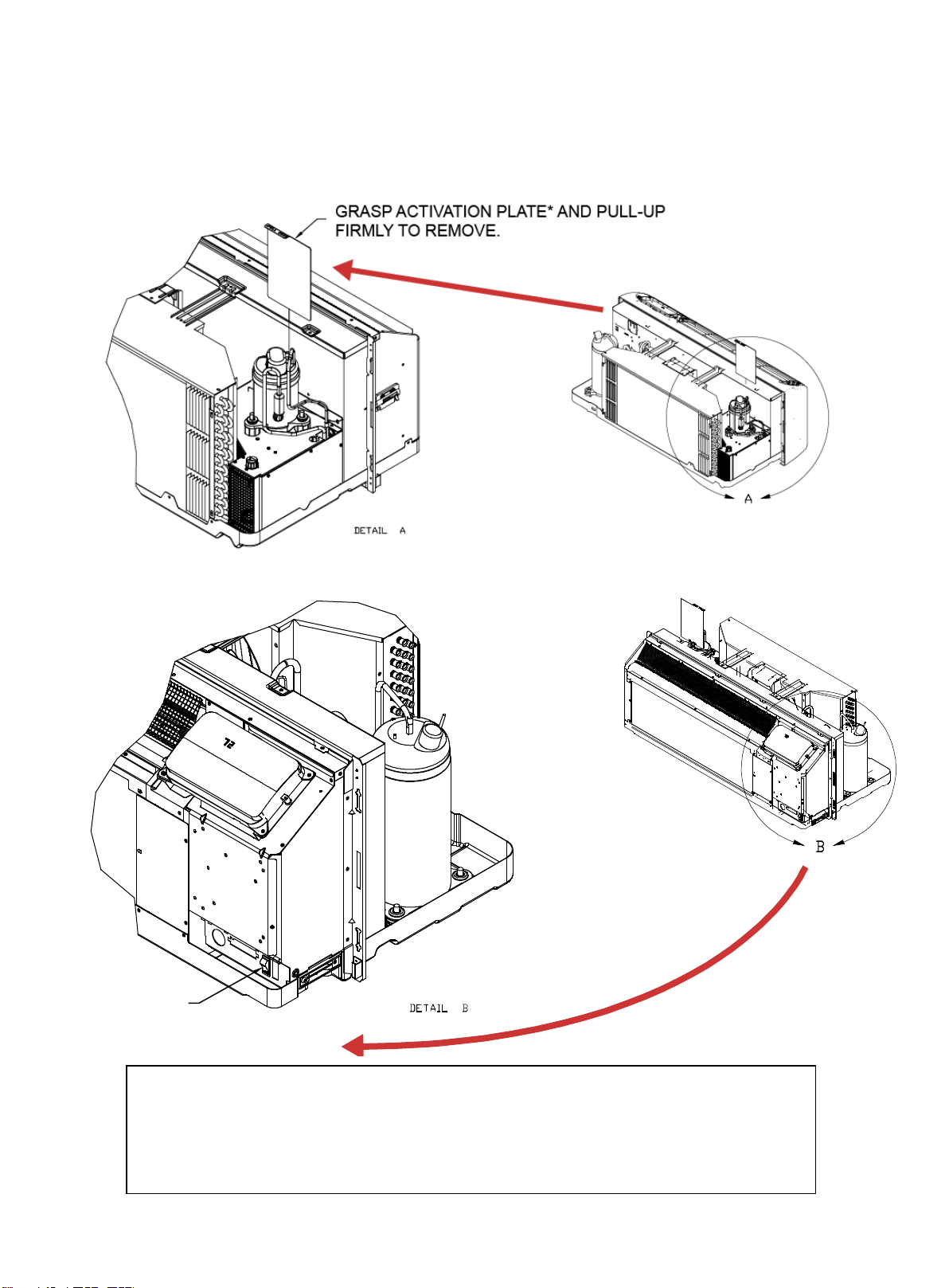
DR.PTAC UNITS (EZDR Series)
Only on EZDR units (these units are equipped with the Make-up Air Dehumidifier option) - Perform the
following steps prior to turning on unit for the first time to activate this option:
STEP 1:
STEP 2:
TURN ON
DR. PTAC
ACTIVATION SWITCH
* IMPORTANT NOTES FOR PEFORMANCE TESTING!
1. Activation Plate must be installed during Performance Testing in order to obtain accurate test
results.
2. DIP Switch 8 on the Main Board must be set to ON (Constant Fan) position during testing (refer to
DIP Switch Settings paragraph on page 11).
3. The DR. PTAC Activation Switch must be in the OFF position when Activation Plate is installed.
4. Set fan speed to maximum speed (High).
- 9 -
WIRING
Cord connection to a wall socket is not permitted for 265V
units. All 265V units must be hard-wired using the hard
wire kit or make use of the plug-in receptacle in the
standard sub-base.
230~208V units are equipped with LCDI power cords and
can open the electrical circuit to the unit. In the event the
unit does not operate, check the reset button located on
or near the head of the power cord as part of the normal
trouble shooting procedure.
WARNING
HIGH VOLTAGE
DISCONNECT ALL POWER BEFORE SERVICING OR
INSTALLING THIS UNIT. MULTIPLE POWER SOURCES MAY
BE PRESENT, FAILURE TO DO SO MAY CAUSE PROPERTY
DAMAGE, PERSONAL INJURY OR DEATH.
DO NOT SERVICE THIS UNIT WITHOUT FIRST SHUTTING OFF
THE POWER TO THE UNIT FROM THE CIRCUIT BREAKER
AND/OR REMOVING THE UNIT CORD SET PLUG FROM THE
WALL OUTLET.
WARNING
TO AVOID THE RISK OF PROPERTY DAMAGE, PERSONAL
INJURY OR FIRE, USE ONLY COPPER CONDUCTORS.
WARNING
TO AVOID THE RISK OF PROPERTY DAMAGE, PERSONAL
INJURY OR FIRE, DO NOT INSTALL WITH POWER CORD
STRETCHED OR UNDER A STRAIN AS THIS MAY CREATE
LOOSE PLUG/RECEPTACLE CONNECTION.
WARNING
TO AVOID THE RISK OF PERSONAL INJURY, WIRING TO
THE UNIT MUST BE PROPERLY POLARIZED AND
GROUNDED.
WARNING
TO AVOID PROPERTY DAMAGE, PERSONAL INJURY OR
DEATH DUE TO ELECTRICAL SHOCK, DO NOT USE AN
EXTENSION CORD WITH THIS UNIT.
WARNING
THIS AIR CONDITIONER IS NOT MEANT TO PROVIDE
UNATTENDED COOLING OR LIFE SUPPORT FOR PERSONS
OR ANIMALS WHO ARE UNABLE REACT TO THE FAILURE
OF THIS PRODUCT.
THE FAILURE OF AN UNATTENDED AIR CONDITIONER MAY
RESULT IN EXTREME HEAT IN THE CONDITIONED SPACE
CAUSING OVERHEATING OR DEATH OF PERSONS OR
ANIMALS.
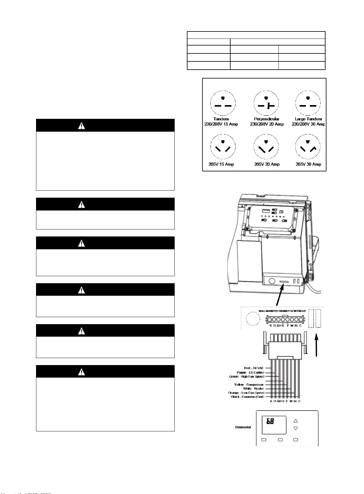
VOLTAGE MEASUREMENTS
Once the unit is properly wired, measure the unit supply
voltage. Voltage must fall within the voltage utilization
range given in Chart 3.
Operating Voltage
Unit Voltage
Voltage Utilization Range
Rating
Minimum Maximum
230/ 208
197 253
265 238 292
Chart 3 -Operating Voltage
Fig 7. Receptacles/Sub-bases
Fig 8. Wall Mounted Thermostat Wiring
- 10 -
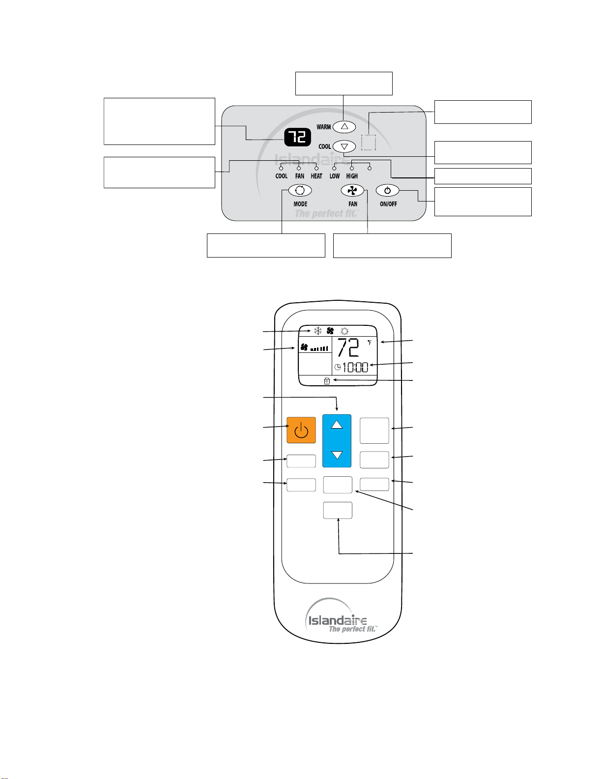
OPERATING INSTRUCTIONS
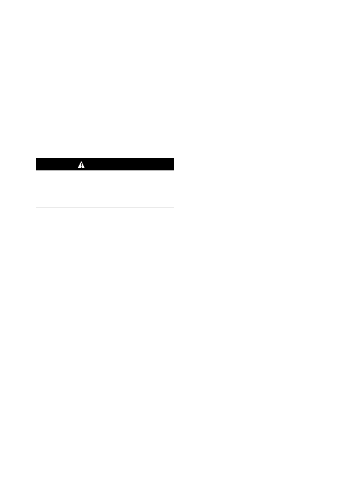
Fig 9. Use of Unit-Mounted Control Panel
Fig 10. Use of Hand-Held Remote Controller
Operation mode indicator lamps
When the unit operates in heat,
cool or fan mode, the correspond-
ing indicator lamp will be active.
MODE button
Press this button to select either cool,
fan or heat operational mode.
FAN SPEED button
Press this button to select fan speed
(low, high or auto).
ON/OFF button
Press this button to turn the
unit ON or OFF.
Fan speed indicator lamp.
COOL button
Press this button to set room
temperature cooler.
Digital display
In normal operation, it indicates
room TEMP; When pressing WARM
or COOL button, it indicates TEMP
setting. In timer operation, it
indicates timer setting. In failure
operation, it indicates failure code.
Receiver of IR remote controller
signal (behind front panel).
WARM button
Press this button to set room
temperature warmer.
AUTO
MIN
°C/°F
FAN
HOLD
MODE
TIMER
HOUR
o
MODE INDICATOR
FAN SPEED INDICATOR
TEMP UP/DWN
FAN SPEED SET
TIMER ON/OFF
TIMER ADJUST
TEMP INDICATOR
HOLD INDICATOR
TIMER DISPLAY
POWER
MODE
HOLD
°C/°F SET
CLOCK ADJUST
- 11 -
COOL/FAN/HEAT MODE OPERATION
PROCEDURE
Control Panel:
Press the ON/OFF button.
Press the MODE button, select the operation mode:
cool/fan/heat.
Press + or - button to set your desired temperature. The
setting temperature range is 60 - 90 °F (16 - 32 °C).
Press the FAN button, to set your desired air flow rate:
low/high/auto.
Remote Controller:
●
Press the Power button on the remote controller
pointing toward the packaged terminal air conditioner.
●
Press the MODE button to select the operation mode:
Cool/Fan/Heat.
●
Press TEMP UP or TEMP DOWN button to set your
desired temperature. The setting temperature range is
61 - 88 °F (16 - 31 °C).
●
Press the FAN button to set your desired air flow rate
(Auto/High/Low).
Clock Setting (Remote Controller)
When battery cells are inserted, the default time is
automatically set to “12:00” (note that clock is 24 hour
format). Press the MIN button to set to current time.
Timer Setting (Remote Controller)
To adjust the timer setting, use the HOUR button
to select operation time (1 to 12 hours of
operation).
Press the TIMER ON/OFF button to enable/disable
timer function.
SERVICE SETTINGS (Control Panel)
1)
Temperature Unit key: Press + and - buttons
simultaneously for 3 seconds, the temperature is shifted
between Centigrade and Fahrenheit units on the display.
2)
Temperature setting limiting: Press + and FAN
SPEED buttons simultaneously to enter the maximum and
minimum temperature settings (see Chart 3). R1~R8 will
display every 3 seconds. Release the two keys to ensure
the setting is effective and the set values will remain for 5
seconds. The temperature setting range is between
60 °F ~ 90 °F by default.
Chart 3. Temperature Setting Limiting
R1
R2
R3 R4
R5
R6 R7 R8
Heating Temperature Limits(°F)
86
86
90
74
92 90 72 90
Cooling Temperature Limits(°F)
63
65
72
72 67 69 68 60
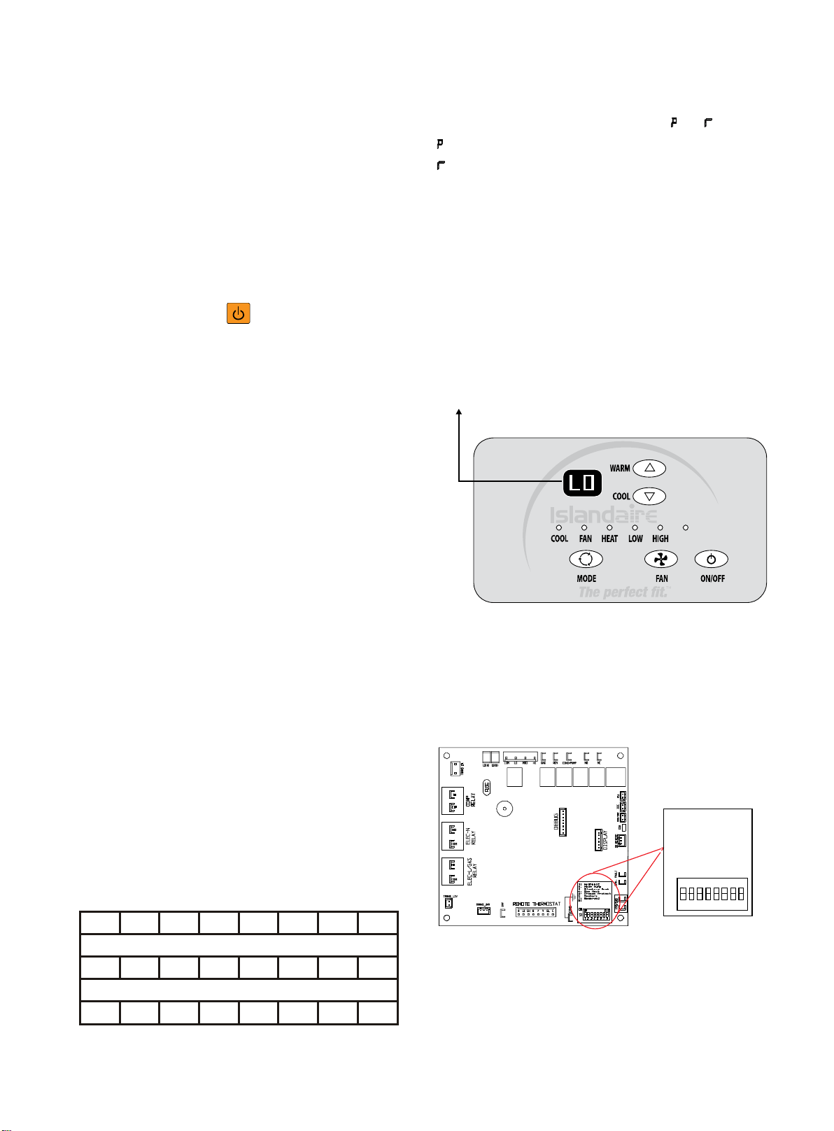
3)
Remote thermostat change: In standby off mode, press
MODE and + buttons simultaneously for 3 seconds, the
buzzer will chime and LED display reads " " or " ".
: unit control panel has control of unit.
: wall thermostat has control of unit.
LOW TEMPERATURE PROTECTION
A standard feature of the Islandaire electronic control
system is the ’Low Temperature Protection’ option. If an
indoor temperature of 50 °F (or below) is detected, the
heat cycle will automatically activate (even if the unit is
in the OFF position). While the ’Low Temperature
Protection’ feature is activated, the letters ‘LO’ will be
displayed. The heat cycle will continue until the room
temperature reaches 55 °F, at which time the unit will
satisfy and shut down.
Note: Cutting power to the unit or setting DIP Switch #5 (located on the
Main Board) to OFF position can interrupt unit function while the ’Low
Temperature Protection’ feature is activated.
DIP SWITCH SETTINGS
A DIP switch is located on the Main Control Board, as
shown in the diagram below. Settings are unit-specific,
depending on equipped options.
‘LO” indicates that the
Low Temperature Protection
feature is activated
AUTO
Fan Con/Cyc for
heating
heating
1: Hydronic
2: Heat Pump
3: Electric Heat
4: Gas Heat
5: Freeze Protect
6: Restart
7: Reserved
8: Fan CON/CYC for
1 2 31 4 6 75 8
ON
S1
ON
ECE
- 12 -
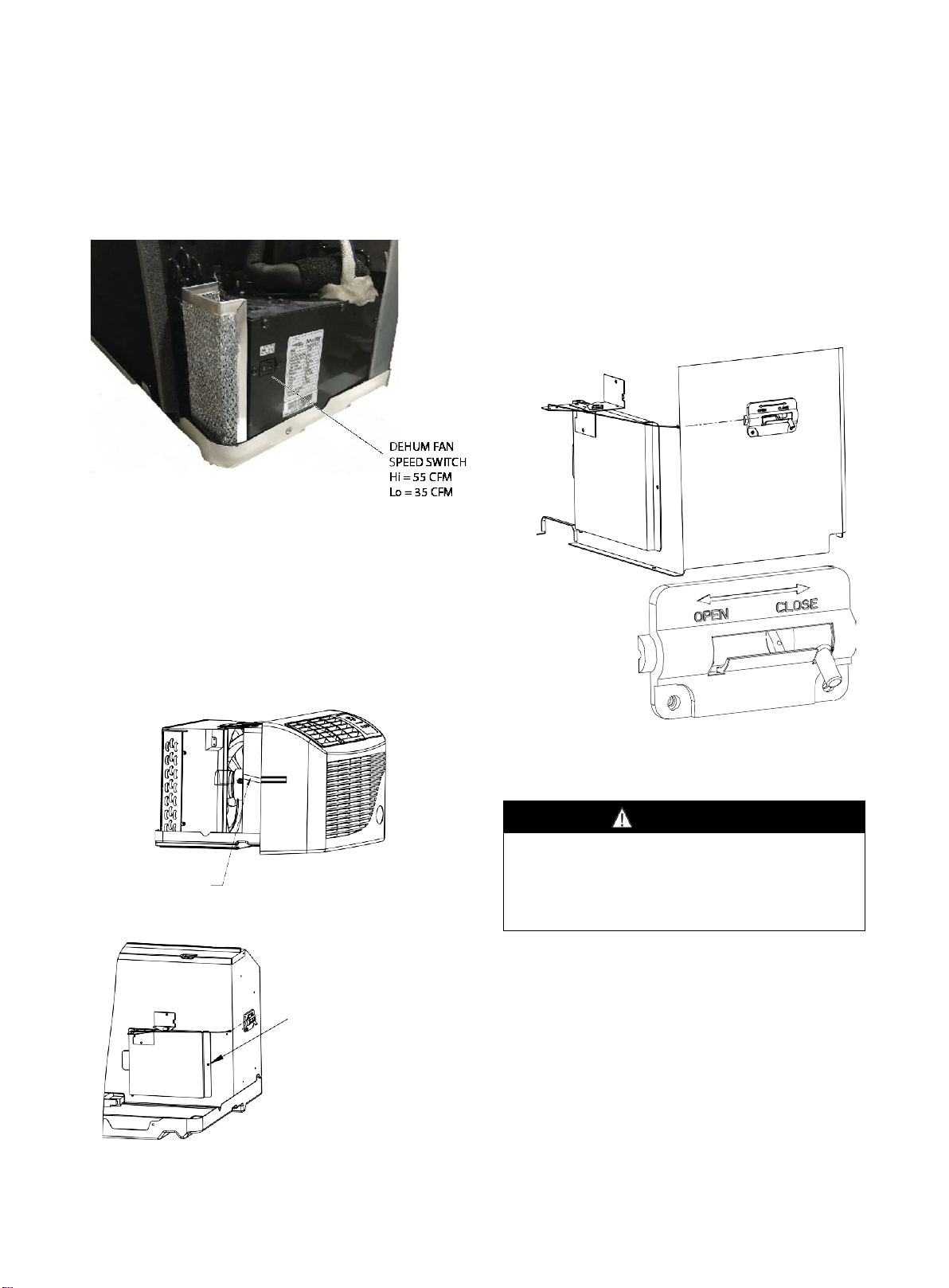
DEHUMIDIFIER OPERATION
(EZDR Series)
On EZDR units, the dehumidifier unit has a two-position
switch (Lo - 35 CFM / Hi - 55 CFM). The factory default
setting is 35 CFM for 7k BTU units (unless otherwise
specified on the sales order) and 55 CFM for all other
BTU units. Set the switch to the desired CFM.
VENTILATION CONTROL
The ventilation control lever is located at left side of unit,
behind the front panel.
NOTE: The vent door shipping tape must be removed
before using vent control lever (see Fig 11 and Fig 12).
When in CLOSE position, only the air inside the room is
circulated and filtered.
When in OPEN position, some outdoor air will be drawn
into room, this will reduce heating or cooling efficiency.
Fig 11. Shipping Tape Location
Fig 12. Shipping Screw Location
The vent control allows outside air to be drawn into the
conditioned area. This outside air can provide ventilation
when the blower is operating, but it will increase the
heating or cooling load and operating costs.
To obtain access to the vent control:
1.
Remove the cabinet front (see Front Removal).
2.
Remove the shipping screw (if installed) from the vent
door.
3.
Remove the label (if present) from over the vent control
lever on the left side of the chassis.
4.
Rotate the vent control lever to either open or close
the damper.
Fig 13. Vent Door Lever Positions
MAINTENANCE AND CLEANING
WARNING
HIGH VOLTAGE
DISCONNECT ALL POWER BEFORE SERVICING OR
INSTALLING THIS UNIT. MULTIPLE POWER SOURCES MAY
BE PRESENT, FAILURE TO DO SO MAY CAUSE PROPERTY
DAMAGE, PERSONAL INJURY OR DEATH.
MONTHLY MAINTENANCE AND
CLEANING
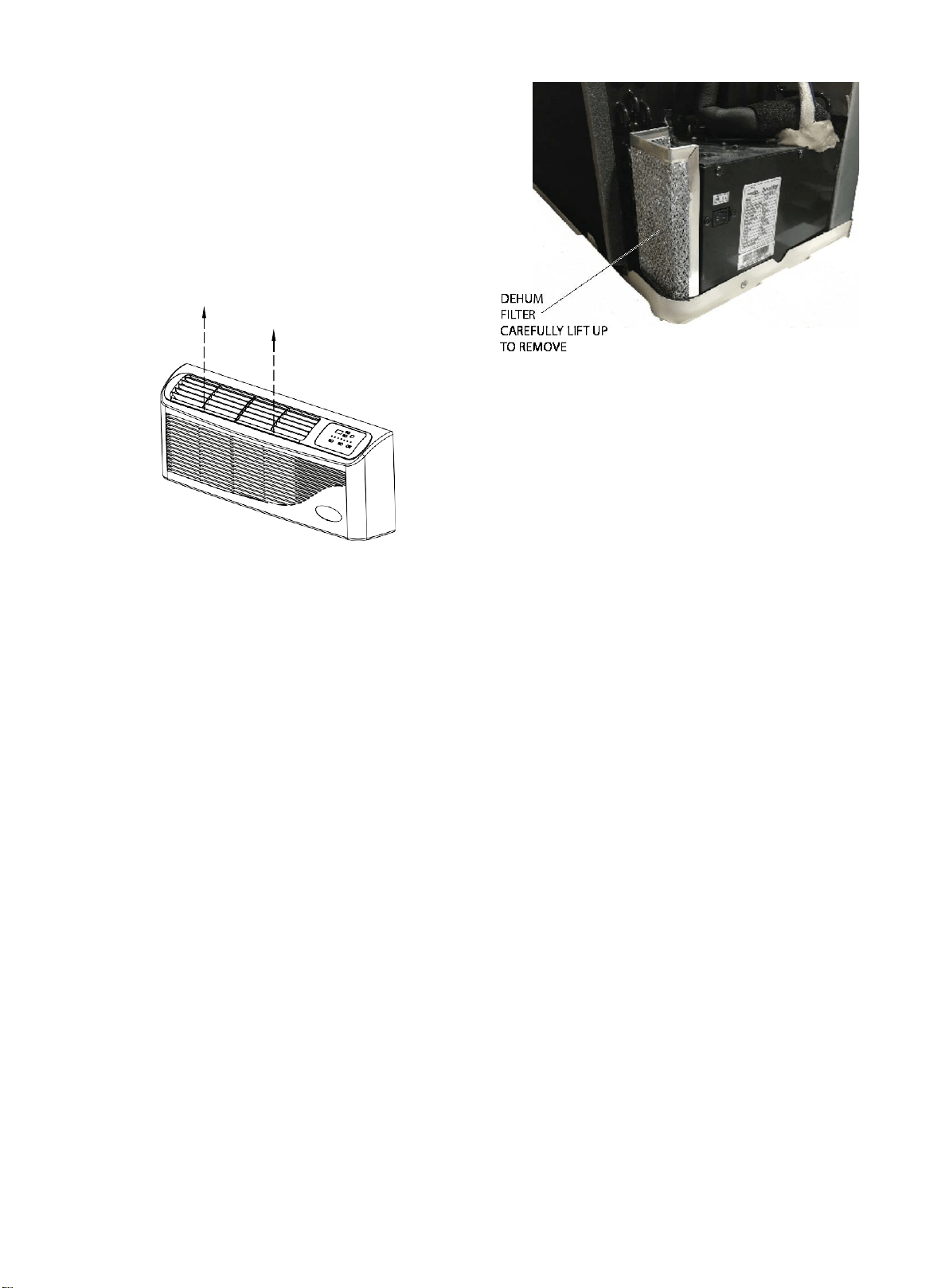
Intake Air Filters
To properly maintain the operational performance of
your PTAC unit, it is extremely important that the inlet
air filters be cleaned once per month or more often if
operated in dusty or dirty locations or conditions. The
intake air filters are constructed of durable
polypropylene. The air intake filters can be easily
inserted into the cabinet front, using the filter guides.
Before cleaning the intake filter, turn the unit off by
setting the mode switch to the OFF position. Filter
should be cleaned as required.
Remove shipping
screw if present
Shipping Tape
- 13 -
The following procedure is used to remove the intake
filter:
1.
Grasp each filter by its molded handle, located on the
front edge of the front, below the discharge grille.
2.
Pull the filter straight up and remove.
3.
Clean filter with vacuum or with running water.
Reverse this procedure to reinstall the filter
Vent Screen
Before cleaning the vent screen, disconnect power to the
unit by unplugging the power cord at the wall outlet or
subbase, or disconnect power at the fuse box or circuit
breaker. If unit is operated with vent door closed, the vent
screen does not need to be cleaned.
1.
Remove the cabinet front as described in Front
Removal.
2.
Remove the six screws securing the chassis to the wall
sleeve.
3.
Slide the chassis out of the wall sleeve far enough so
that the vent screen is accessible.
4.
Clean the vent screen, slide the chassis back into the
wall sleeve, secure it in place with six screws and
reinstall the front cabinet.
Cabinet Front
The cabinet front and discharge air grille can be cleaned
with a water dampened cloth. Under no circumstances
should hydrocarbon-based cleaners (e.g., acetone,
benzene, naphtha gasoline, etc.) or ammonia based
cleaners be used to clean the front or air grilles. Use care
when cleaning the control area.
EZDR Units – Dehumidifier Filter Cleaning
On EZDR Series units, the dehumidifier filter requires
periodic cleaning (quarterly is recommended, more
frequently if located in dusty or corrosive environment).
The filter can be cleaned with water. See figure below for
filter location.
YEARLY MAINTENANCE AND
CLEANING
NOTE: Use a mild biodegradable detergent when
cleaning the unit. Special care must be taken to protect
the unit's control board and other electrical components
from getting any water on them while cleaning. The use of
harsh or caustic cleaning agents or materials such as
bleach or coil cleaners that are not designed for PTAC
products will cause damage or deterioration of the
aluminum fin or coil material and is not recommended.
Care must be taken not to bend the aluminum fin stock.
Routine Scheduled Maintenance
To achieve continuing top performance and high
efficiency, establish a “once a year" cleaning/inspection
schedule for the unit. Take the unit out of the sleeve and
thoroughly clean and rinse. Be sure to include in the
yearly cleaning the evaporator coil, condenser coil, base
pan, and drain passages.
Scheduled maintenance can be accomplished by either
qualified local maintenance staff or by an authorized
servicer. They must follow the instructions described in
this manual.
Adverse Operating Conditions Maintenance
Units operating in dusty or corrosive locations; i.e.,
dusty construction site or sea coast, must be cleaned
more often. A minimum of four (4) times a year will
maintain proper operational conditions and protect unit
components.
Wall sleeve
Clean the wall sleeve while cleaning the unit. The
caulking around the sleeve should be checked to make
sure that any potential air and water openings around
the sleeve are properly sealed. The wall sleeve's level
should also be rechecked. Proper leveling for most
installations are a 1/4 bubble tilt to the outside and level
from right to left. Contact your sales person for detailed
maintenance or cleaning instructions.
Filter is removed by
grasping the filter's top and
gently pulling up
Front removal is not
necessary to remove the
filter
- 14 -
WARNING
DO NOT USE COMMERCIAL GRADE COIL CLEANERS.
SOME OF THESE CLEANERS MAY CONTAIN ETHYLENE
DIAMINE TETRACETIC ACID (EDTA) WHICH CAN SHORTEN
THE LIFE OF THE CONDENSER COIL.
WARNING
HIGH PRESSURE AND HIGH TEMPERATURE CLEANING IS
NOT RECOMMENDED.
DOING SO COULD DAMAGE THE ALUMINUM FIN STOCK
AND ELECTRICAL COMPONENTS.
Base pan and Condenser coil
Before cleaning the base pan and condenser coil, turn
OFF unit mode switch and disconnect power to the unit.
To disconnect power, either unplug the power cord at the
wall outlet or subbase, or disconnect power at the fuse box
or circuit breaker.
1. Create a water tight seal by tightly covering the entire
control panel area and fan motor with plastic. Creating this
seal prevents water from entering the control area or the
fan motor and damaging the unit.
2. Spray condenser coil and base pan down with water.
Next spray a mild biodegradable detergent onto the
condenser coil and base pan. Let set for five (5) minutes.
3. Rinse condenser coil and base pan with water again.
NOTE: Ensure water pressure is no higher than that of
an ordinary garden hose and the water temperature no
higher than 120 °F.
4. Tilt the non-compressor side of the unit up no higher
than 45° and allow water to drain out the other side of the
unit.
5. Remove excess water left in the base pan by wiping the
base pan with a dry cloth.
6. Remove the water-tight seal from the motor and
control panel area.
7. Reinstall unit back into wall sleeve.
8. Allow unit to dry for 24 hours before reapplying power.
When power is reapplied, test unit for proper operation.
9. Place a non-acidic algaecide in the base pan to inhibit
bacteria growth. Ensure the algaecide is compatible with
wet coil operation and is not corrosive to the coil.
Clearance Check
Clearances around the unit should also be checked to
make sure that the intake air and discharge air paths
have not become blocked or restricted. A minimum of
eight inches clearance is needed from unit to furniture,
beds, or other objects for proper operation. Restricted
discharge or intake air will reduce the unit's operational
performance. In severe airflow restrictions damage can
occur to unit components such as the compressor,
electric heater or fan motor.
NORMAL OPERATING SOUNDS
AND CONDITIONS
Water trickling sounds
Water is picked up and distributed over the coil. This
improves the efficiency and helps with water removal.
Water dripping
Water will collect in the base pan during high humidity
days. This can cause overflow and drip from the outside
of the unit.
Air sounds
The fan cycle switch sets the operational mode of the
fan. In the ON position, the fan will run continuously
whenever power is applied in this mode. In the AUTO
position, the fan will cycle on and off with the
compressor or electric heater.
Starting delay
You may notice a few minutes delay in starting if you try
to restart the unit too soon after turning it off or if you
adjust the thermostat right after the compressor has shut
off. This is due to a built-in delay to protect the
compressor.
Buzzer Response
The buzzer will chime “Di” (0.1 sec) in response when
receiving the effective order from key pad control and
remote control.
- 15 -
DIAGNOSTIC CODES
The Diagnostic Maintenance provides detailed
information on PTAC control operation and operational
status including present modes, failures, airflow restriction
warnings , operating temperatures, and past failures.
To enter Diagnostic Status Report mode, press and hold
the temp down ( − ) key and the FAN SPEED key
simultaneously for a period of five (5) seconds.
The diagnostic information is presented in the following
format: X.Y
Where:
“X” indicates the failure type:
1 = anti-frost
2 = overheat
3 = high pressure
4 = anti-freezing
“Y” indicates the number of occurrences within a one
hour period (0~4: time of protection)
Note: If the number above is greater than 4, the
compressor shuts off and a Failure Code appears in the
display (e.g., “E8”). See chart below for Error Codes and
their meanings:
Failure Code
Content of defect
E2
Indoor coil temperature sensor failure
E3
Indoor temperature sensor failure
E5
Outdoor coil temperature sensor failure
E8
Overheating protection
/
defrosting
E9
High pressure protection
-16-
TROUBLESHOOTING
POSSIBLE CAUSES
SOLUTIONS
UNIT DOES NOT START
●
Unit may have become unplugged
●
Check that plug is plugged securely in wall receptacle.
Note: Plug has a test/reset button on it. Make sure the
plug has not tripped.
●
Fuse may have blown
●
Replace the fuse
●
Circuit breaker may have been tripped
●
Reset circuit breaker
●
Unit may be off or in wall thermostat mode.
●
Turn unit on (bottom right button on keypad).
●
Unit may be in a protection or diagnostic failure mode.
●
Check diagnostic codes - See section on diagnostic codes.
STRANGE NUMBERS/CHARACTERS ON DISPLAY
●
Unit may be in a protection or diagnostic failure mode.
●
The unit may be in a diagnostic condition. Check
diagnostic codes - See section on diagnostic codes.
●
Check section on DIP switch settings to verify dip switches
are set properly.
●
The unit may be set for °C (instead of °F), see the keypad
operation section.
UNIT MAKING NOISES
●
Clicking, gurgling and whooshing noises are normal
during operation of unit.
UNIT NOT COOLING / HEATING ROOM
●
Unit air discharge section is blocked
●
Make sure that curtains, blinds or furniture are not
restricting or blocking unit airflow.
●
Temperature setting is not high or low enough.
●
Reset to a lower or higher temperature setting.
●
Set point limits may not allow the unit to heat or cool the
room to the desired temperature settings. Check Service
Settings section.
●
Unit air filters are dirty.
●
Remove and clean filters.
●
Room is excessively hot or cold when unit is started.
●
Allow sufficient amount of time for unit to heat or cool the
room. Start heating or cooling early before outdoor
temperature, cooking heat or gatherings of people make
room uncomfortable.
●
Vent door left open.
●
Close vent door.
●
Unit may be in a protection or diagnostic failure mode.
●
Check section on Diagnostic Codes.
●
Compressor is in protective time delay
Note: To prevent tripping of the compressor overload, there
is a protective time delay (approx. 3 minutes) on starting the
compressor, such as after a power outage, or restarting after
it has been turned off.
●
Wait approximately 3 minutes for compressor to start.
WATER DRIPPING OUTSIDE
●
If a drain kit has not been installed, condensation runoff during
very hot and humid weather is normal. If a drain kit has been
installed and is connected to a drain system, check gaskets
and fittings around drain for leaks and/or clogs.
WATER DRIPPING INSIDE
●
Wall sleeve is not installed level.
●
Wall sleeve must be installed level for proper drainage of
condensation. Check that installation is level and make
any necessary adjustments.
ICE OR FROST FORMS ON INDOOR COIL
●
Low outdoor temperature.
●
If outdoor temperature is approximately 55 °F (12.8 °C) or
below, frost may form on indoor coil when unit is in Cooling
mode. Switch unit to FAN operation until ice or frost melts.
●
Unit air filters are dirty.
●
Remove and clean filters.
COMPRESSOR PROTECTION
●
Power may have cycled putting compressor in Random
Compressor restart protection.
●
To prevent short cycling of the compressor whenever the unit
is plugged in or power has been cycled, a random compressor
restart will occur. The restart delays start-up of the compressor
for approximatley 3 minutes, and then forces a minimum
compressor run time of 3 minutes.

-17-
NOTES
______________________________________________________________________________________________
______________________________________________________________________________________________
__________________________________________________________________________________________________________
__________________________________________________________________________________________________________
__________________________________________________________________________________________________________
__________________________________________________________________________________________________________
__________________________________________________________________________________________________________
__________________________________________________________________________________________________________
__________________________________________________________________________________________________________
__________________________________________________________________________________________________________
__________________________________________________________________________________________________________
__________________________________________________________________________________________________________
__________________________________________________________________________________________________________
__________________________________________________________________________________________________________
__________________________________________________________________________________________________________
__________________________________________________________________________________________________________
__________________________________________________________________________________________________________
__________________________________________________________________________________________________________
__________________________________________________________________________________________________________
__________________________________________________________________________________________________________
__________________________________________________________________________________________________________
__________________________________________________________________________________________________________
__________________________________________________________________________________________________________
__________________________________________________________________________________________________________
__________________________________________________________________________________________________________
__________________________________________________________________________________________________________
__________________________________________________________________________________________________________
__________________________________________________________________________________________________________
__________________________________________________________________________________________________________
__________________________________________________________________________________________________________
__________________________________________________________________________________________________________
__________________________________________________________________________________________________________
__________________________________________________________________________________________________________