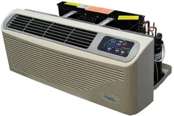
EZ Series 42 & EZ Series DR (DR.PTAC)
42” W x 16” H PTAC/PTHP
Perfect t for Replacing Existing 42” x 16” Units and for New
Construction Projects
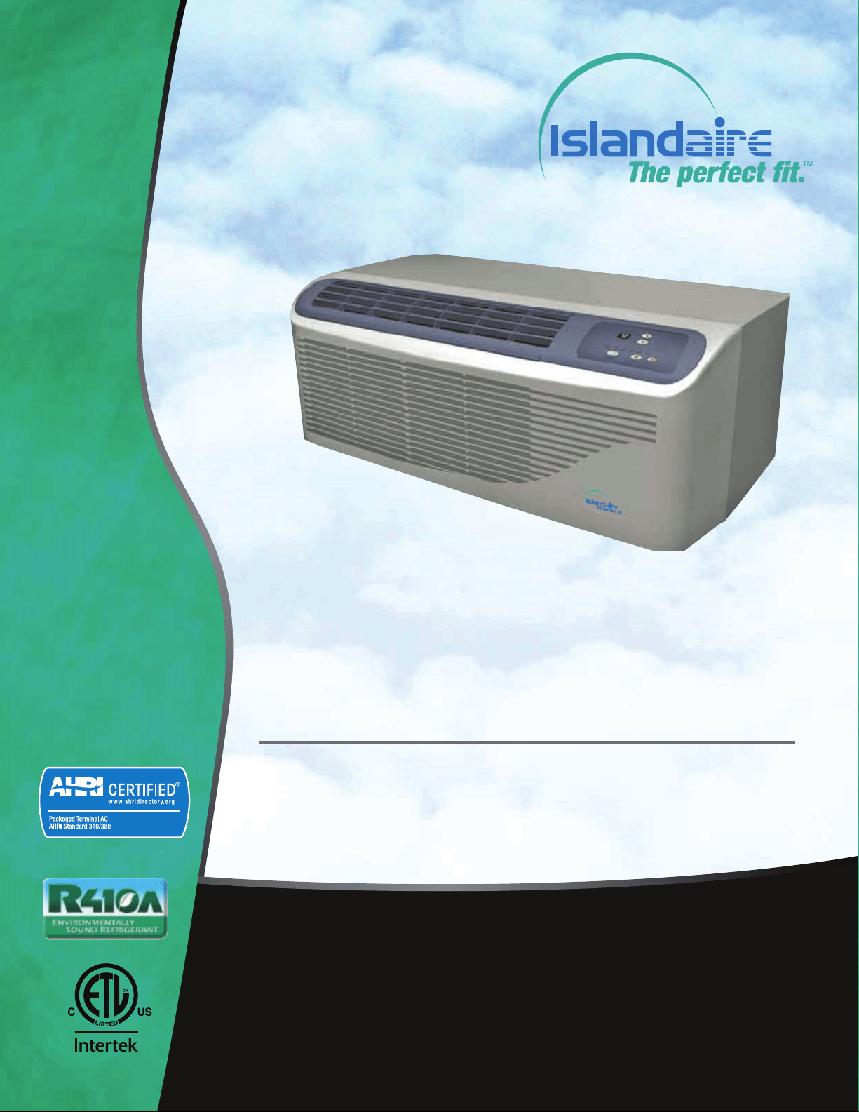
Engineering Manual
MANUFACTURER OF QUALITY AIR CONDITIONING AND HEATING PRODUCTS
6140207 Rev. 052019
AHRI Certication applicable to EZ42
models only

Manufacturer of Quality Air Conditioning and Heating Products • www.islandaire.com • sales@islandaire.com • (800)-886-2759
B
Table of Contents
INTRODUCTION ............................................................... 1
APPLICATIONS .................................................................. 2
New Construction ....................................................................... 2
Retrot/Replacement .................................................................. 2
Application Considerations ....................................................... 3
Guaranteed Quality .................................................................... 3
Indoor Air Quality - DR. PTAC (EZDR Series Units Only) . 3
PRODUCT OVERVIEW ..................................................... 4
Quiet Operation .......................................................................... 4
Durable Construction ................................................................ 4
Seacoast Construction ................................................................ 4
CHASSIS FEATURES AND BENEFITS ............................. 6
Slide Out Chassis ......................................................................... 6
Wall Sleeve ................................................................................... 6
Exterior Louver/Grilles – ........................................................... 6
Removable Front Panel .............................................................. 6
Discharge Grille ........................................................................... 6
Tangential Blower Wheel ........................................................... 7
Slinger Fan ................................................................................... 7
Venturi Shroud ............................................................................ 7
Return Air Filters ........................................................................ 7
Fresh Air Vent .............................................................................. 7
ORDERING DATA EZ SERIES 42 .................................... 8
Model Nomenclature .................................................................. 8
Replacement Guide ..................................................................... 8
PERFORMANCE DATA EZ SERIES 42 ........................... 9
Performance Data for EZ42 Series ............................................ 9
Heating options ........................................................................... 9
Electrical ....................................................................................... 9
ORDERING DATA EZ SERIES DR DR.PTAC .............. 10
Model Nomenclature .................................................................. 10
Replacement Guide ..................................................................... 10
PERFORMANCE DATA EZ SERIES DR DR.PTAC ..... 11
Performance Data for EZDR Series .......................................... 11
Heating options ........................................................................... 11
Electrical ....................................................................................... 11
DR. PTAC FEATURES ......................................................... 12
DR.PTAC INFORMATION ................................................. 13
DIMENSIONAL DRAWINGS ............................................. 14
OPTIONS AND ACCESSORIES ......................................... 15
Hard Wire Kit .............................................................................. 15
Remote Control ........................................................................... 15
Optional 2 Stage Heater ............................................................. 15
Condensate Drain Kit ................................................................. 15
Subb as e ......................................................................................... 15
Lateral Duct Kit Assembly ......................................................... 15
CLEARANCES AND PROJECTIONS ................................ 16
INSTALLATION INSTRUCTIONS .................................... 17
WALL SLEEVE INSTALLATION INSTRUCTIONS .......... 18
Preparing the Wall Opening ...................................................... 18
Framing ........................................................................................ 18
Wall Sleeve Installation .............................................................. 19
CONDENSATE DRAIN KIT ............................................... 20
Condensate Drain Kit ................................................................. 20
External Drain Installation ........................................................ 20
Internal Drain Installation ......................................................... 21
REAR GRILLE INSTALLATION INSTRUCTIONS .......... 22
Stamped Rear Grille .................................................................... 22
Architectural Rear Grille ............................................................ 23
Subbase Assembly & Installation .............................................. 26
SUBBASE ASSEMBLY & INSTALLATION ........................ 26
CHASSIS INSTALLATION ................................................. 28
FRONT COVER INSTALLATION & REMOVAL .............. 29
Front Cover Removal ................................................................. 29
FRESH AIR VENT ............................................................... 30
Fresh Air Vent .............................................................................. 30
Lateral Duct Kit ........................................................................... 30
MAINTENANCE ................................................................. 31
Air Intake Filters ......................................................................... 31
Routine Maintenance ................................................................. 31
INFORMATION FOR HEAT PUMP UNITS ..................... 32
Heat Pump Features .................................................................... 32
ELECTRICAL INSTALLATION ......................................... 33
Hardwire Kit ................................................................................ 33
LCDI Cords .................................................................................. 33
PTAC Wire Harness Kit ............................................................. 33
Heaterless Units ........................................................................... 33
Voltage Measurements ............................................................... 33
WIRING DIAGRAM ........................................................... 34
SYSTEM CONTROLS AND MANAGEMENT ................... 35
User Interfaces ............................................................................. 35
Remote Control ........................................................................... 35
Digital Control Panel .................................................................. 35
Wall ermostats ........................................................................ 35
Front Desk Control ..................................................................... 35
System Management Soware ................................................... 36
Fan Cycle Control ....................................................................... 36
Room Freeze Prevention ............................................................ 36
High Temperature Compressor Protection ............................. 36
Low Temperature Compressor Protection .............................. 36
Diagnostic Soware .................................................................... 36
Custom Operation and Continual Room Temperature
Monitoring .................................................................................. 36
DIGITAL CONTROL PANEL ............................................. 37
Control panel ............................................................................... 37
Power Control ............................................................................. 37
Display .......................................................................................... 37
Mode Control - Cool, Fan, and Heat ........................................ 37
Fan Speed Control - Low, High, and Auto............................... 38
Temperature Controls ................................................................ 38
Operating Guidelines ................................................................. 38
REMOTE THERMOSTATS ................................................. 39
Remote ermostat Control ...................................................... 39
Wireless Wall ermostat .......................................................... 39
Energy Saving Options ............................................................... 39
REMOTE THERMOSTAT INTERFACE ............................ 40
CONTROL BOARD ............................................................. 41
TEMPERATURE LIMITING .............................................. 42
Set Temperature Limiting .......................................................... 42
ERROR CODES ................................................................... 43
Diagnostic & Error Codes ......................................................... 43
Packaged Terminal Cooling Unit with Heat Pump or
Electric Heating .......................................................................... 44
PERFORMANCE SPECIFICATIONS ................................ 44
WARRANTY ........................................................................ 52
Islandaire reserves the right to make changes in design and construction at any time without notice.

Manufacturer of Quality Air Conditioning and Heating Products • www.islandaire.com • sales@islandaire.com • (800)-886-2759
1
Our Company
Islandaire is the fastest growing specialty air conditioning and heating
manufacturer in the country. Founded in 1992 by Robert Hansen, it
has grown into a multi-million dollar company in just a few short years.
Islandaire builds a full complement of high quality thru-the-wall replacement
air conditioners and heat pumps, water source heat pumps, and gas units in
St. James, New York. Each model ts perfectly into the existing original wall
case assembly, thereby saving both time and money during installations.
Our Engineering, Production, Sales and Customer Service departments have
been fully integrated to provide the maximum degree of user satisfaction.
We at Islandaire feel that this team approach to manufacturing produces a
superior overall product and assures a larger degree of exibility in design and
production scheduling to meet tight prototyping or construction timetables.
The Perfect Fit
ru-wall air conditioners were developed in the late 1950’s. Over the next
forty years many companies engineered, manufactured and installed a variety
of dierent units throughout the United States and Canada. Today, a number
of these companies are no longer in business, or have discontinued their line
of thru-wall air conditioners and no longer carry replacement parts.
Islandaire oers replacement air conditioners and heat pumps that are inter-
changeable with units no longer available from the original manufacturer.
Our units are engineered to t perfectly within the existing wall case, thereby
reducing installation time and expense. ey are manufactured at our mod-
ern 75,000 square foot plant on Long Island in New York.
ank you for considering our products,
e Islandaire Team
Introduction

Manufacturer of Quality Air Conditioning and Heating Products • www.islandaire.com • sales@islandaire.com • (800)-886-2759
2
Applications
e EZ Series 42 and DR units are designed and manu-
factured for new construction or the replacement of
packaged terminal air conditioning (PTAC) units in an
existing building. Our packaged terminal air condition-
ing (PTAC) units provide year-round comfort control for
hotels, motels, apartments, dormitories, shops, nurs-
ing homes, assisted living centers, satellite oces, room
additions and other applications that require economical
heating and cooling.
e product is designed for individually-zoned, comfort-
controlled, heating and cooling. e unit width is an
industry standard 42”. We oer our cooling chassis to
operate with cooling only or electric heat. e design
standards, heavy duty construction and the focus on
indoor noise reduction has created our unit as the pre-
mier unit of the future. Individually controlled PTAC
units are ideal for rooms that are not occupied during
vacancies, holidays, weekends or nights. Individual units
allow tenants to choose the degree of comfort and oper-
ating economy.
ermostat and fan controls are built into the digital
touch-pad, plus all units have the exibility to convert
to a wall thermostat control, or interface into energy
management systems. Whether you are designing a new
structure or replacing PTAC units in an existing build-
ing, Islandaire will meet your needs.
New Construction
e Islandaire EZ42 and EZDR Packaged Terminal Air
Conditioning (PTAC) unit is designed to meet the needs
of the architect, engineer, and contractor. For unit instal-
lation, Islandaire’s expert support network will assist in
all applicable aspects of the construction project, from
preparing a budget to start-up.
ADVANTAGES FOR NEW CONSTRUCTION
Design Flexibility For e Architect Engineer
•Super-quiet performance, indoors and out
•No bulky duct system
•No separate equipment room
•No water towers or additional cooling equipment
•Less sensitivity or building orientation
•Optional architectural grille to permit custom
exterior appearance
LOWER OPERATING COSTS & RELIABLE COMFORT FOR THE
OCCUPANT
Islandaire helps lower utility costs with energy ecient
units that exceed industry standards. Energy savings
are achieved in both heating and cooling environments
through ecient mechanical design and onboard elec-
tronic logic. Separate indoor and outdoor fans provide
lower operating costs. Energy management soware is
built into the unit’s standard digital controls.
ese units may also qualify for electrical power com-
pany rebates. (Consult your local utility provider for
rebate opportunities.)
Retrofit/Replacement
Islandaire PTAC units are engineered to t perfectly
within most existing wall sleeves, thereby reducing
installation time and expense. ere is no time wasted
on redesigning an existing wall opening or removing an
old wall sleeve. Just slide the old chassis out and replace
with a new one from Islandaire.
EZ Quick slide-out chassis eases installation into the wall
sleeve. Rapid servicing reduces downtime: complete
chassis can be replaced in minutes without disrupting
other occupants.

Manufacturer of Quality Air Conditioning and Heating Products • www.islandaire.com • sales@islandaire.com • (800)-886-2759
3
Applications (cont.)
Application
Considerations
It is important for air conditioning systems to be prop-
erly sized for each application in order to achieve desired
temperature and humidity levels. It is strongly recom-
mended that a professional engineer match the PTAC
units with the building structure and climate.
e following application considerations are all impor-
tant in choosing the proper PTAC system for the build-
ing structure.
UNDERSIZING
If a PTAC unit is undersized (cooling capacity is less than
required capacity for an application), the unit will not be
able to cool the space down to the desired temperature
during very hot days.
OVERSIZING
If a PTAC unit is oversized (cooling capacity is greater
than required capacity for the specic application), the
unit will cool the space down to the desired temperature
too quickly creating a cool, yet excessively humid, space.
AIR INFILTRATION
Excessive air inltration can intensify problems associ-
ated with undersizing or oversizing a PTAC unit. is
can be the cause of insucient cooling, dehumidica-
tion, or heating. Sources of air inltration include vents,
gaps around windows and doors, and improperly sealed
oors, ceiling or wall joints.
Guaranteed Quality
Each Islandaire unit is designed to operate quietly and
eciently and is backed by the best warranty program
available. Standard warranty is one year parts and labor
including ve year compressor part only warranty or two
year parts only including ve year compressor part only
warranty.
Whether it is an exact replacement unit or a new con-
struction project, Islandaire is the smart choice for all
your air conditioning and heating needs.
Indoor Air Quality - DR.
PTAC (EZDR Series Units
Only)
In addition to an already quiet unit, we have
co-developed an indoor air quality option called
Dr.PTAC.
Dr.PTAC is currently designed as a two-stage system.
e primary stage conditions room air and tempers
the air to acceptable air quality levels. e secondary
stage brings in conditioned outside air at a rate of up
to 55 CFM, to compensate for toilet exhaust and room
occupancy, and continuously pressurizes the room. e
secondary stage is initiated by an outdoor humidistat that
allows the unit to condition the incoming fresh air about
50% RH. e system can be calibrated to run at higher
outdoor RH levels, but the recommended maximum set
point 50% outdoor RH. When outdoor RH levels are
above the set point, the secondary compressor is initiated
and conditions make up air below the set point.
e secondary fan continuously runs allowing fresh, con-
ditioned, make-up air at a rate of up to 55 CFM (leaving
coil CFM) to enter the room. e unit is manufactured
in accordance to ARI, UL, CSA standards for the primary
side and AHAM and UL standards for the secondary
side.

Manufacturer of Quality Air Conditioning and Heating Products • www.islandaire.com • sales@islandaire.com • (800)-886-2759
4
Product Overview
Quiet Operation
e cross-ow tangential fan wheel design used in our
EZ42 and EZDR units provide whisper quiet operation
while delivering maximum airow required for proper
air circulation. Separate indoor and outdoor fan motors
further reduce operating sound levels and costs.
e heavy gauge construction of the chassis and cabinet
minimizes vibration for quieter operation. Vibration iso-
lators on the rotary compressor keep it running smoothly
and quietly. e unit bulkhead is fully insulated to
decrease outdoor sound transmission.
e compressor is isolated to minimize vibration and
sound transmission for quiet operation.
Durable Construction
•Islandaire PTAC/PTHP units are built with
durable, quality components designed for continu-
ous operation in all environments.
•Our wall sleeves are constructed of thick 18-gauge
steel with a tough baked-on nish for maximum
durability.
•e outdoor fan motor is totally enclosed, prevent-
ing damage from moisture and debris introduced
by extreme weather conditions. Both indoor and
outdoor fan motors are permanently lubricated for
extended life.
•Electrical components are located on the indoor
side of the wall protecting them from driving rain
and humidity.
•e compressor is a reliable, high eciency design
rotary compressor. It is hermetically sealed and
designed for continuous operation.
•Repositionable discharge grille allows angle of air-
ow to be adjusted according to application. Made
from tough plastic material that won’t rust, resists
scratches and is easy to clean.
Seacoast Construction
Application of air conditioning equipment in a corrosive
environment requires special consideration. e cor-
rosive nature of salt water vapor, chlorine and acid vapor,
demands a unit that can withstand these environments.
Any metal portion that is exposed to a corrosive vapor
must be specially treated.
All Islandaire PTAC units have special corrosion protec-
tion that can help dramatically extend the life of the unit.
Listed below are just some of the components that feature
corrosion protections:
•
Wall Sleeve – e entire wall sleeve is con-
structed of 18-gauge steel. Treated inside and
outside with a baked-on based powder coat paint
to protect it from the corrosive eects of salt spray.
•
Base Pan – Base pan has a corrosion resistant
coating to protect it from the elements.
•
Condenser Coil – Protective coating applied to
the coil to prevent corrosion and weathering.
•
Condenser Fan Blade – Constructed of strong
engineering plastic that has excellent ame resis-
tance and dimensional stability over a wide range
of service temperatures.
•
Condenser Fan Motor – Specially coated by the
manufacturer.
•
Compressor – Protective coating applied by the
manufacturer on the exterior to enhance equip-
ment life and performance.
•
Outdoor Louver – Made of aluminum, etched
and anodized for maximum corrosion protection.
Available in stamped or architectural styles. Can
be painted in a wide choice of colors.
Standard on All Models:
Corrosion protection treatment shields the EZGS
unit from corrosive environments and extends
the life of the unit, especially in coastal locations.
Manufacturer of Quality Air Conditioning and Heating Products • www.islandaire.com • sales@islandaire.com • (800)-886-2759
5
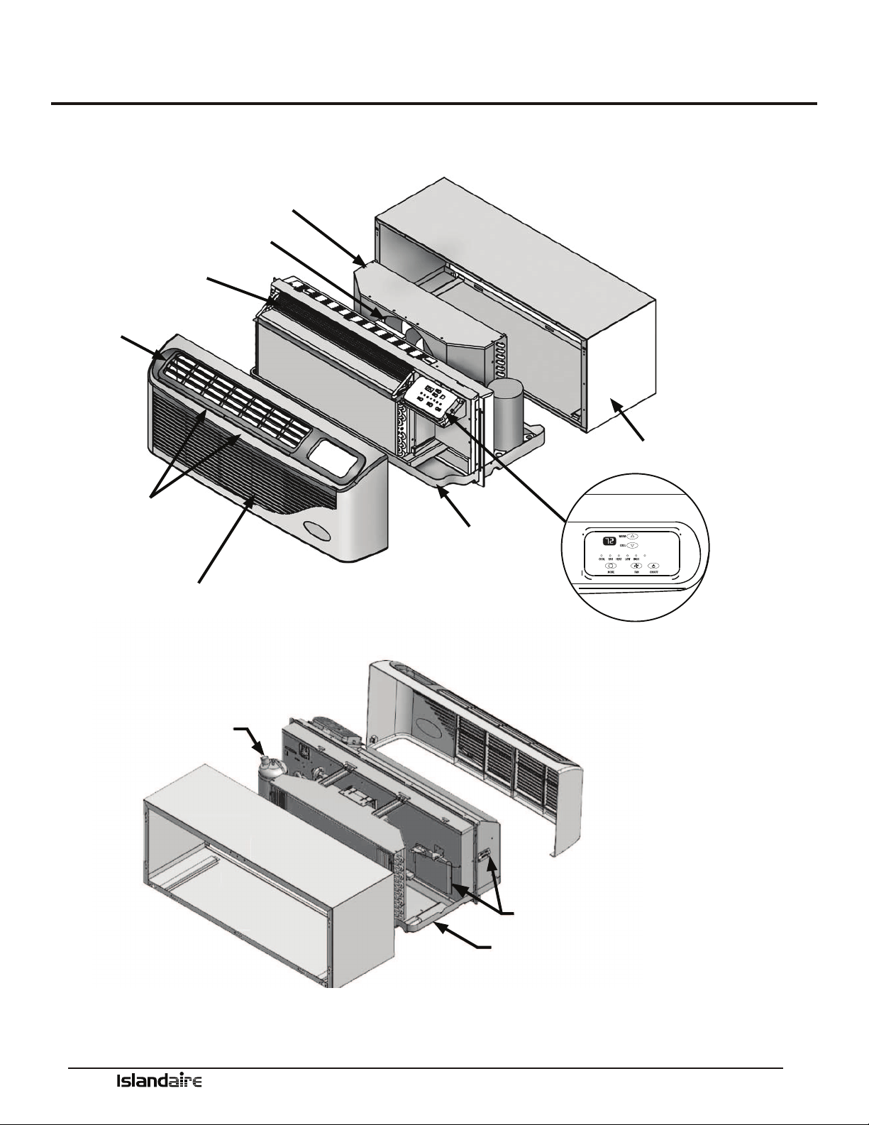
Product Overview (cont.)
Islandaire manufactures the EZ42/EZDR loaded with standard features that
other manufacturers oen consider optional.
AUTO
VENTURI SHROUD
SLINGER FAN BLADE
TANGENTIAL BLOWER WHEEL
DISCHARGE GRILLE
RETURN AIR
FILTERS
REMOVABLE FRONT PANEL
WALL SLEEVE
DIGITAL TOUCHPAD CONTROL /
DIAGNOSTIC CENTER
CHASSIS
COMPRESSOR
FRESH AIR INTAKE
SLOPED BASEPAN
Manufacturer of Quality Air Conditioning and Heating Products • www.islandaire.com • sales@islandaire.com • (800)-886-2759
6
Slide Out Chassis
•Slide-out chassis makes installation simple
•All components are readily accessible to service personnel
•On-board diagnostic soware and display help diagnose potential
problems
•Designed to replace older units with minimal modication
•Isolated rotary compressor design for continuous ecient, reliable
and quiet operation
See page 28 for chassis installation instructions
Wall Sleeve
Part Number 2401135-00
•ick insulation on the top and sides to reduce noise and increase
eciency
•Heavy 18 gauge steel with powder paint coating for maximum scratch,
dent and corrosion resistance
See page 19 for wall sleeve installation instructions
Exterior Louver/Grilles –
•Architectural extruded aluminum grille, Part Number 6070422
•Custom colors available (Ask for our color chart sheet)
•Stamped Grille, Part Number 6070264
See page 22- for exterior grille installation instructions
Removable Front Panel
Part Number 6130133
•Made from durable plastic that won’t rust, resists scratches and is easy
to clean
•Quick removal ensures shorter installation time and faster
service calls
•Easy access to removable lters
Discharge Grille
Part Number 6130134
•Tough ABS plastic is durable, easy to clean and maintain
See page 29 for front cover installation instructions
Chassis Features and Benefits
Manufacturer of Quality Air Conditioning and Heating Products • www.islandaire.com • sales@islandaire.com • (800)-886-2759
7
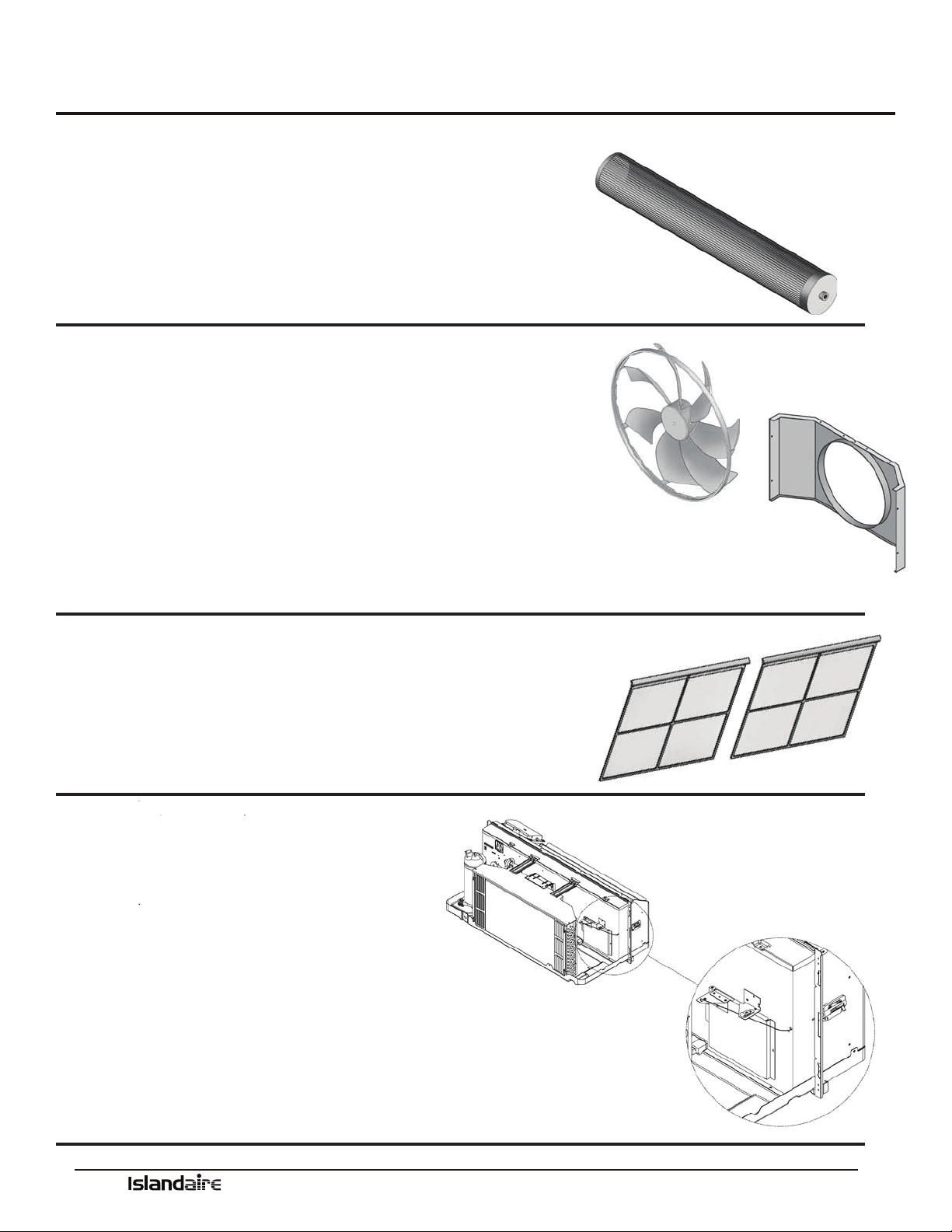
Tangential Blower Wheel
•Creates extremely quiet indoor operating environment
•Generates a balanced and constant airow into the room
Slinger Fan
•Curved fan blades increase airow across the outside coil
•Creates a quiet operating environment outside of building
•Slinger ring eciently removes condensate and increases cooling
Venturi Shroud
•Works with the fan to maximize air ow and increase eciency
•Removes easily for quick access when cleaning the condenser coil
Return Air Filters
(2 per) Part Number 6080067
•Easily removable from the front of the unit for cleaning
•Filters the circulated air inside the room
•Keeps the system clean and working eciently
•Clean lters increase life of the system components
See page 39 for maintenance information
Fresh Air Vent
•Allows fresh air to be drawn into the room
when indoor fan is operating
•Manual control allows uninterrupted
operation
See page 30 for fresh air vent information
Chassis Features and Benefits (cont.)

Manufacturer of Quality Air Conditioning and Heating Products • www.islandaire.com • sales@islandaire.com • (800)-886-2759
8
Ordering Data - EZ Series 42
Model Nomenclature
Please review the nomenclature/model number break-
down below for the EZ Series 42 options.
Units are available in four cooling BTUH sizes:
7,500; 9,500; 12,000; 15,000
Voltage options are: 115V, 208/230V, and 277V.
Control choices include a unit mounted digital control;
multiple wired wall mounted heating/cooling thermo-
stats and a wireless wall thermostat, with occupancy
sensor control.
Replacement Guide
MANUFACTURER MODEL WALL OPENING DIMENSION DISCHARGE RETURN AIR HEAT TYPE
16 ¼” x 42 ¼” ANGLED FLAT BOTTOM FRONT ELECTRIC HYDRONIC
AC HP
AMANA PTC ••••••••
CLIMATE
MASTER
PIP ••••••••
MC QUAY
PDE ••••••••
PSE ••••••••
MQE ••••••••
GREE ETAC ••••••••
TRANE PTE ••••••••
LG LP ••••••••
GE AZ ••••••••
EZ - Cooling Chassis
07 - 7,500 BTU
09 - 9,500 BTU
12 - 12,000 BTU
15 - 15,000 BTU
1 - Standard Cooling
2 - Heat Pump
1 - 115v, 20 Amps
2 - 230v, 20 Amps
3 - 230v, 30 Amps
4 - 230v, Junction Box
5 - 115v, 15 Amps
6 - 115v, Junction Box
7 - 277v, 20 Amps
8 - 277v, Junction Box
9 - 230v, 15 Amps
F - 277v, 30 Amps
1 - None
E - Wireless Thermostat (type must be speci-
ed when placing order)
F - Wall Thermostat Interface, Master
G - Wall Thermostat Interface, Slave
N - Wall Thermostat Interface, Std. Elect.
Cntrls
S - Std. Electronic Controls (Unit Mounted)
4 - Front Ret./Top Dis.
0 - Special
6 - Standard
A - None
C - Energy Mgt. N/O
D - Energy Mgt. N/C
A - Manual Fresh Air
B - Motorized Fresh Air
SYSTEM TYPE
MODEL TYPE
COMPONENT
COOLING CAPACITY
VOLTAGE / LINE CORD
ROOM CONTROLS
HYDRONIC OPTIONS
FUNCTIONAL OPTIONS
IDENTITY CODE
RETURN DISCHARGE OPTIONS
EZ 42 12 1 2 A 1 S 4 6 A A
3 - Dual Stage 3.4 kW Electric
4 - Dual Stage 5.0 kW Electric
7 - 1.7 kW Elec. Heat (115v Only)
A - None Cooling Only
B - 2.0 kW Elec. Heat (208v - 277v)
Y - 1.3 kW Elec. Heat (115v Only)
HEATING OPTIONS
POWER
MANAGEMENT OPTIONS
POWER
MANAGEMENT CODES
A - A
P - C
T - D
42 - ISLANDAIRE 42 X 16 PTAC
Manufacturer of Quality Air Conditioning and Heating Products • www.islandaire.com • sales@islandaire.com • (800)-886-2759
9
••••••••
••••••••
••••••••
••••••••
••••••••
••••••••
••••••••
••••••••
••••••••
Performance Data for EZ42 Series
MODELS
EZ07 EZ09 EZ12 EZ15
VOLTS
230 208 277 115 230 208 277 115 230 208 277 230 208 277
BTUH COOL
7,200 6,800 7,200 9,800 9,500 9,300 9,500 12,500 12,500 12,300 12,500 14,500 14,300 15,000
AMPS COOL
2.46 2.52 2.11 7.22 3.41 3.70 2.83 9.30 4.65 5.05 3.86 5.96 6.49 5.20
WATTS COOL
565 525 585 830 785 770 785 1,070 1,070 1,050 1,070 1,370 1,350 1,440
EER
12.8 13.0 12.3 11.8 12.1 12.1 12.1 11.7 11.7 11.7 11.7 10.6 10.6 10.4
CFM HIGH COOL
375 340 360 340 375 340 360 340 375 340 360 360 360 360
CFM LOW COOL/
HEAT
260 240 260 240 260 240 260 240 260 240 260 260 240 260
BTUH HEATING
6,400 6,300 6,100 8,500 8,500 8,300 8,500 11,400 11,400 11,000 11,400 13,600 13,200 14,000
WATTS HEATING
530 520 520 710 700 685 710 980 950 915 980 1180 1150 1300
C.O.P.
3.54 3.55 3.44 3.51 3.55 3.55 3.51 3.40 3.52 3.52 3.40 3.38 3.36 3.16
NOISE INDOOR/
OUTDOOR (DBA)
45/69 45/69 45/69 45/69 45/69 45/69 45/69 45/69 45/69 45/69 45/69 45/69 45/69 45/69
SHIPPING
WEIGHT (LB)
132 132 132 132 132 132 132 132 132 132 132 132 132 132
Heating options
Electrical
EZ42
LINE VOLTAGE 115 115 208/230 208/230 208/230 277 277
MAXIMUM AMPERAGE 15 20 12 16 24 16 24
WALL SOCKET
CONFIGURATION
RECEPTACLE NUMBER
NEMA
5-15R
NEMA
5-20R
NEMA
6-15R
NEMA
6-20R
NEMA
6-30R
NEMA
7-20R
NEMA
7-30R
ELECTRICAL HEAT OPTIONS 1.3 1.7 2.5 3.6 4.2 - 5.0 2.5 - 4.2 5.0
(1) Voltage is Single Phase, Alternating Current and R.M.S.
(2) Amp values are for heating element only
Heating Option Voltage (I) Wattage BTU/h Amps (2)
3
208 2,780 9,500 13.37
230 3,400 11,600 14.78
277 3,600 12,300 13.00
4
208 4,090 13,900 19.66
230 5,000 17,100 21.74
277 5,000 17,100 18.05
7 115 1,700 5,800 14.78
B
208 1,635 5,600 7.87
230 2,000 6,800 8.70
277 2,500 8,500 9.03
Y 115 1,300 4,400 11.30
Performance Data - EZ Series 42
Manufacturer of Quality Air Conditioning and Heating Products • www.islandaire.com • sales@islandaire.com • (800)-886-2759
10
Ordering Data - EZ Series DR (DR.PTAC)
MODEL TYPE
EZ - Cooling Chassis
07 - 7,500 BTU
09 - 9,500 BTU
12 - 12,000 BTU
15 - 15,000 BTU
1 - Standard Cooling
2 - Heat Pump
2 - 230v, 20 Amps
3 - 230v, 30 Amps
4 - 230v, Junction Box
7 - 277v, 20 Amps
8 - 277v, Junction Box
9 - 230v, 15 Amps
F - 277v, 30 Amps
1 - None
E - Wireless Thermostat (type must be speci-
ed when placing order)
F - Wall Thermostat Interface, Master
G - Wall Thermostat Interface, Slave
N - Wall Thermostat Interface, Std. Elect. Cntrls
S - Std. Electronic Controls (Unit Mounted)
4 - Front Ret./Top Dis.
0 - Special
6 - Standard
A - None
C - Energy Mgt. N/O
D - Energy Mgt. N/C
SYSTEM TYPE
COMPONENT
COOLING CAPACITY
VOLTAGE / LINE CORD
ROOM CONTROLS
HYDRONIC OPTIONS
FUNCTIONAL OPTIONS
POWER
MANAGEMENT OPTIONS
IDENTITY CODE
RETURN DISCHARGE OPTIONS
EZ DR 12 1 2 A 1 S 4 6 A A
3 - Dual Stage 3.4 kW Electric
4 - Dual Stage 5.0 kW Electric
A - None Cooling Only
B - 2.0 kW Elec. Heat (208v - 277v)
HEATING OPTIONS
A - None
F - 250W Fresh Air Heater
G - 400W Fresh Air Heater
POWER
MANAGEMENT CODES
DR - DR.PTAC 42 X 16
A - A
P - C
T - D
Model Nomenclature
Please review the nomenclature/model number break-
down below for the EZ Series DR options.
Units are available in four cooling BTUH sizes:
7,500; 9,500; 12,000; 15,000
Voltage options are: 208/230V and 277V.
Control choices include a unit mounted digital control;
multiple wired wall mounted heating/cooling thermo-
stats and a wireless wall thermostat, with occupancy
sensor control.
Replacement Guide
MANUFACTURER MODEL WALL OPENING DIMENSION DISCHARGE RETURN AIR HEAT TYPE
16 ¼” x 42 ¼” ANGLED FLAT BOTTOM FRONT ELECTRIC HYDRONIC
AC HP
AMANA PTC ••••••••
CLIMATE
MASTER
PIP ••••••••
MC QUAY
PDE ••••••••
PSE ••••••••
MQE ••••••••
GREE ETAC ••••••••
TRANE PTE ••••••••
LG LP ••••••••
GE AZ ••••••••
Manufacturer of Quality Air Conditioning and Heating Products • www.islandaire.com • sales@islandaire.com • (800)-886-2759
11
Performance Data - EZ Series DR (DR.PTAC)
Performance Data for EZDR Series
MODELS
EZ07 EZ09 EZ12 EZ15
VOLTS
230 208 277 230 208 277 230 208 277 230 208 277
BTUH COOL
7,200 6,800 7,000 9,500 9,300 9,200 12,000 11,800 12,000 14,500 14,300 15,000
AMPS COOL
2.63 2.74 2.09 3.63 3.82 2.89 4.98 5.31 4.08 6.17 6.73 5.36
WATTS COOL
605 570 580 835 795 800 1,145 1,105 1,130 1,420 1,400 1,485
EER
11.9 11.9 12.1 11.4 11.7 11.5 10.5 10.7 10.6 10.2 10.2 10.1
CFM HIGH COOL
375 340 360 375 340 360 375 340 360 360 360 360
CFM LOW COOL/HEAT
260 240 260 260 240 260 260 240 260 260 240 260
BTUH HEATING
6,400 6,100 6,100 8,500 8,300 8,500 11,000 10,800 11,400 13,600 13,200 14,000
WATTS HEATING
560 535 520 710 685 710 950 900 1000 1180 1155 1300
C.O.P.
3.35 3.34 3.44 3.51 3.55 3.51 3.39 3.51 3.34 3.38 3.35 3.16
NOISE INDOOR/OUT-
DOOR (DBA)
45/69 45/69 45/69 45/69 45/69 45/69 45/69 45/69 45/69 45/69 45/69 45/69
SHIPPING WEIGHT (LB)
132 132 132 132 132 132 132 132 132 132 132 132
Heating options
(1)Voltage is Single Phase, Alternating Current and R.M.S. (2) Heating Capacity (B.T.U./Hr.) based on indoor blower motor and heating elements. (3) Amp values are a combination of indoor
blower motor and heating elements. (4) Minimum Circuit Ampacity ratings conform to the National Electric Code; however local codes should apply
Electrical
EZDR
LINE VOLTAGE 208/230208/230208/230277277
MAXIMUM AMPERAGE1216241624
WALL SOCKET CONFIGURATION
RECEPTACLE NUMBERNEMA 6-15RNEMA 6-20RNEMA 6-30RNEMA 7-20RNEMA 7-30R
ELECTRICAL HEAT OPTIONS 2.53.64.2 - 5.02.5 - 4.25.0
Dehumidifier
Capabilities
Outdoor
% RH
Outdoor
Temp (F)
H2O
Removal
(L/Day)
60
80
7.9
60
90
7.8
62
84
9.6
70
81
11.18
85
90
14.4
82
82
17.02
Heating Option Voltage (I) Wattage BTU/h Amps (2)
3
208 2,780 9,500 13.37
230 3,400 11,600 14.78
277 3,600 12,300 13.00
4
208 4,090 13,900 19.66
230 5,000 17,100 21.74
277 5,000 17,100 18.05
B
208 1,635 5,600 7.87
230 2,000 6,800 8.70
277 2,500 8,500 9.03

Manufacturer of Quality Air Conditioning and Heating Products • www.islandaire.com • sales@islandaire.com • (800)-886-2759
12
Dr. PTAC Features
FEATURES:
•Up to 55 CFM Continuous Conditioned fresh air
•Motion sensor/door switch capable
•Superior temperature control
•Dehumidication of room air
•Modern and elegant appearance
•Washable lter for easy cleaning
•User friendly control panel
•Hand held remote controller
•Wired wall thermostat capable
•Compressor freeze protection
•Self diagnosis
•Random Auto Re-Start
•Compressor time delay
•Front desk control
•Room side freeze protection
OPTIONS:
•Two-stage electric heat
•Electric heat add-on for the DR.PTAC fresh air
system for cold climates
ACCESSORIES:
•Condensate removal kit
•18 gauge insulated wall sleeve
•Wired remote thermostat
•Wireless remote thermostat
•I.R. motion sensor
•Door Switch
•Subbase kit
•Electrical subbase kit
•Duct kit
•Locking control cover
LEED POINTS ACHIEVED:
1. Energy Ecient Design and compliance with
ASHRAE 62.1 and ASHRAE 90.1
2. Indoor Environmental Quality with improved IAQ
through make up air.
3. Innovation in Design through the use of a “Make Up
Air PTAC”.
4. Regional Design through the use of Dr. PTAC in
high humidity climates.
5. Diverting Construction Debris through the use of
re-usable containers.
6. Recycling/reusing Dr. PTAC in secondary market
where the “rst costs” are prohibitive to owners.

Manufacturer of Quality Air Conditioning and Heating Products • www.islandaire.com • sales@islandaire.com • (800)-886-2759
13
Dr.PTAC information
e Dr. PTAC system is an add on system to our standard PTAC unit to provide conditioned makeup air into a space thru
the PTAC unit by providing up to 55 CFM of outdoor air 24/7 by forced fan and cycling dehumidier compressor based on
outdoor relative humidity levels.
Dr. PTAC was created to solve issues with dehumidication in rooms and to introduce fresh air due to deciencies of
oxygen levels. Dr. PTAC is not only a PTAC but a Conditioned Make Up Air unit. New ASHRAE studies show that many
illnesses in hotel rooms can be attributed to oxygen decient atmospheres. Dr. PTAC solves that issue by introducing tem-
pered conditioned make up air that satises both humidity level introduction and supplied oxygen.
Dr. PTAC is a two-stage system. e primary unit is responsible for control of Sensible Heat that is introduced into the
room via make up air temperature and thermal load of the occupants. e secondary unit is primarily a dehumidica-
tion unit that provides up to 55 CFM of outside fresh air into the room. e correction of the Sensible Temperature comes
from the main PTAC unit, which provides additional dehumidication with temperature correction. Overall unit e-
ciency over standard PTAC’s is approximately 3% improvement. e compressor/dehumidication process is controlled by
a humidistat (factory set at 50% RH), which is monitoring the outdoor relative humidity level and is adjustable by a quali-
ed servicer. When the outdoor humidity level raises above 50% RH, the compressor and dehumidication process starts.
Below 50% RH, compressor operation and dehumidication is stopped, however, fan operation continues to provide up to
55 CFM of outdoor air into the space.
e dehumidication system has a temperature switch which is monitoring both the refrigeration and the outdoor air
temperatures. If the outdoor air goes below 38 °F, the compressor is disabled with fan operation continuing to provide
outdoor air into the space. All dehumidier controls and safeties are automatically reset. An optional air tempering heater
is available for the fresh air system for applications where operation in cold winter climates is required. Condensate from
the dehumidier drains into the PTAC drain pan, where it is also slung onto the condenser coil for re-evaporation outside
when the A/C runs. Excess condensate is drained into the wall case, which can then either drain to the outside through the
louver OR is piped to a drainage system via an optional drain kit.
ADVANTAGES OF THE DR. PTAC SYSTEM:
1. Lower installation/renovation costs than typical DOAS*
2. Decrease inconvenience to customer due to construction/installation of a DOAS* system
3. More humidity control in a room over use of a simple PTAC vent or Power vent system
4. Allows fresh make up air to travel entirely across sleeping and living areas of a room, exiting through a duct or under
the door
*DOAS = Dedicated Outdoor Air System
Manufacturer of Quality Air Conditioning and Heating Products • www.islandaire.com • sales@islandaire.com • (800)-886-2759
14
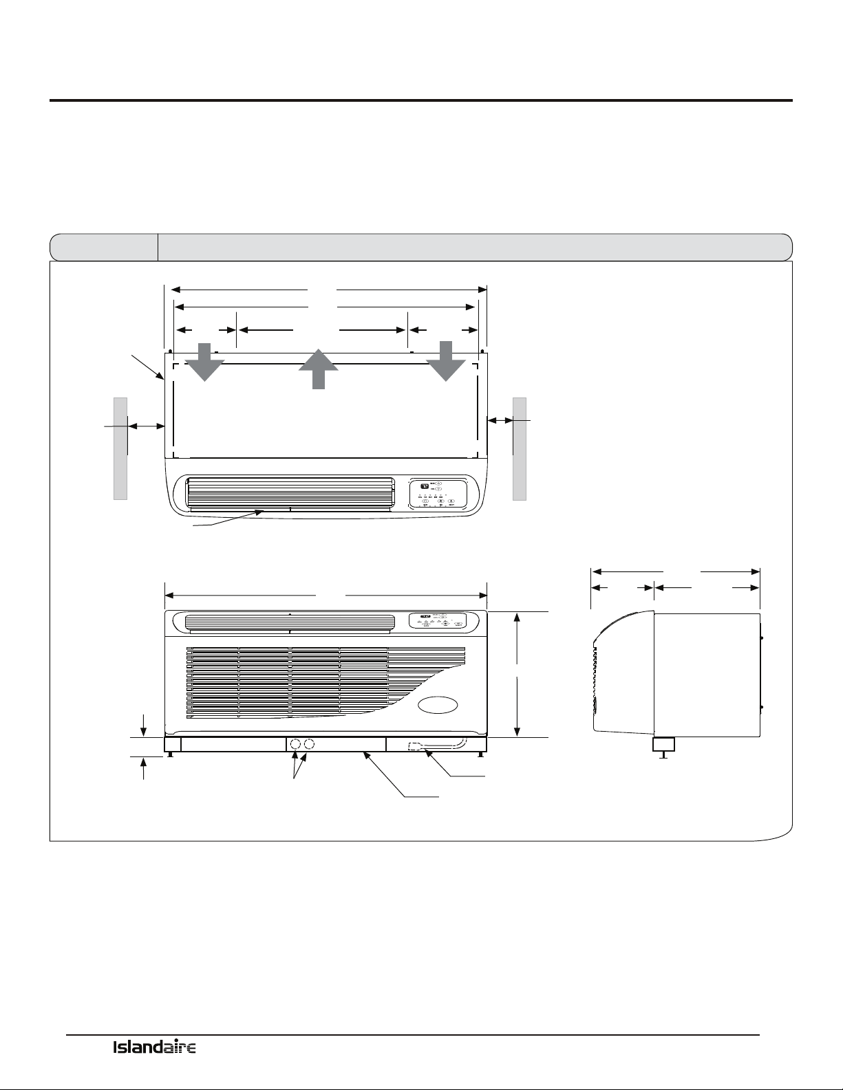
Dimensional drawings
Units must be installed in accordance with all applicable codes. Ensure that there is adequate clearance for servicing and
proper operation. A minimum of 18 inches in front of the chassis is required. Provide additional space for service techni-
cian to work on the unit. Ensure that drapes, beds, bedspreads, furniture, etc., DO NOT block either return or discharge
air openings.
AUTO
42”
0” min
1” recom-
mended
WALL SLEEVE
FRONT DISCHARGE
GRILLE
3” MIN.
6 1/8”
AIR FLOW
40”
24 5/16”
AIR FLOW
ELECTRICAL KNOCKOUTS
42”
9 9/16”
AIR FLOW
0” min
1” recommended
16”
CORDSET
SUBBASE
Front View
7 7/8”
21 5/8”
13 3/4”
Side View
Top View
Figure 1 Dimensional Drawings
Manufacturer of Quality Air Conditioning and Heating Products • www.islandaire.com • sales@islandaire.com • (800)-886-2759
15
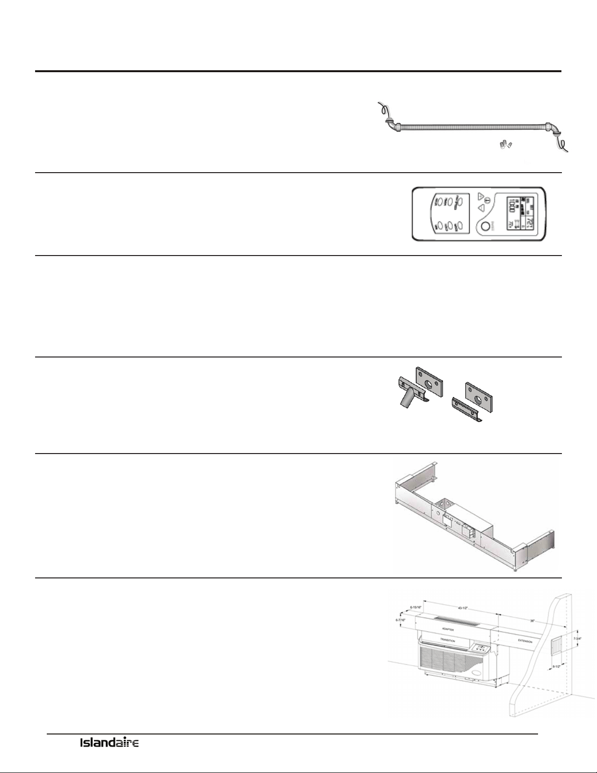
Options and Accessories
Hard Wire Kit
Part Number 6040756
•Used in place of a plug-in power cord
•
All 265V units require either a hard wire kit or electric subbase
See page 31 for electrical information
Remote Control
Part Number 6040694
•
Ability to control PTAC from anywhere in the room
•Large full function display
•Operates on two AA batteries
Optional 2 Stage Heater
AVAILABLE ON 208/230 VOLT UNITS WITH REMOTE THERMOSTATS
•Reduces energy cost during the heating season
•Maximizes year-round comfort
•Available in 3.6 kW and 5.0 kW only
Condensate Drain Kit
Part Number 4090661
•
Attaches to wall sleeve base pan to control condensate removal
•Can be adapted for le or right side exterior drainage or internal
drain connection
See page 20 for drain kit installation instructions
Subbase
•Provides secure enclosure for electrical connections
•Provides structural support for units that extend into the room
•Includes leveling legs for support and precise adjustment
See page 26 for subbase installation instructions
Lateral Duct Kit Assembly
•Allows the air from one PTAC unit to be shared by an
adjacent room
•e kit mounts to the top of the unit and can be congured
for either right or left discharge
Manufacturer of Quality Air Conditioning and Heating Products • www.islandaire.com • sales@islandaire.com • (800)-886-2759
16
Clearances and Projections
MINIMUM PROJECTION INTO ROOM
e wall sleeve will need to be installed so that the sleeve
projects into the room a minimum amount according to
the table below.
OPTION
MINIMUM
PROJECTION
INCHES (MM)
WALL SLEEVE ONLY .25 (6)
SUBBASE KIT
4.5(114)
LEVELING LEGS KIT 2 (50)
DUCT KIT 1.0 (25.4)
MINIMUM CLEARANCE FOR SUBBASE, LEVELING LEGS, AND
LATERAL DUCT KIT
Installation of these kits requires drilling of mounting
holes on both sides of the wall sleeve. e minimum
required clearance distance between the wall sleeve and
oor wall is shown in the rst column of the table below.
e minimum clearance between the wall sleeve and
adjacent (perpendicular) walls is shown in the second
column. If the distance between wall sleeve and adjacent
wall will be at or near the minimum clearance distance,
mount these kits on the sleeve before installing the sleeve
in the wall.
OPTION
MINIMUM CLEARANCES
TO FLOOR WALLS
INCHES INCHES
WALL SLEEVE ONLY 3 0
SUBBASE KIT 3 3.25
LEVELING LEGS 3 3
DUCT KIT 3 0
DRAIN KIT 3 1.5
HARD-WIRE KIT 3 1.25
OUTSIDE WALL ROOM SIDE
1/4”
MINIMUM
WALL
SLEEVE
MINIMUM
ROOM SIDE
PROJECTION
(SEE TABLE)
Figure 2 Minimum Projection Into Room
OUTSIDE WALL ROOM SIDE
1/4”
MINIMUM
WALL
SLEEVE
MINIMUM
ROOM SIDE
PROJECTION
(SEE TABLE)
MINIMUM
CLEARANCE
TO FINISHED
FLOOR
(SEE TABLE)
Figure 3 Minimum Clearance From Floor
OUTSIDE WALL
INTERNAL
ADJACENT
WALL
TOP VIEW
WALL SLEEVE
MINIMUM
CLEARANCE FROM WALL
Figure 4 Minimum Clearance From Walls
Manufacturer of Quality Air Conditioning and Heating Products • www.islandaire.com • sales@islandaire.com • (800)-886-2759
17
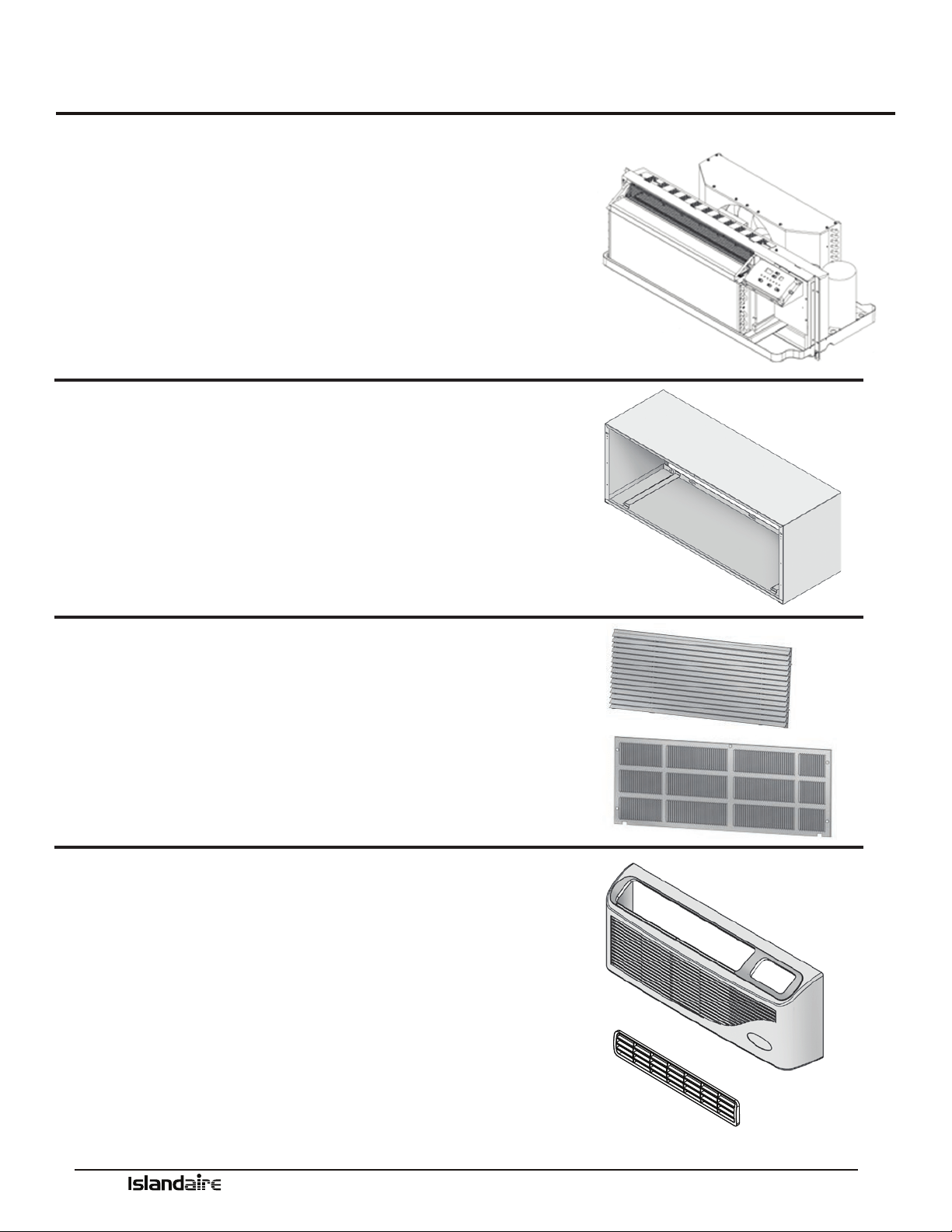
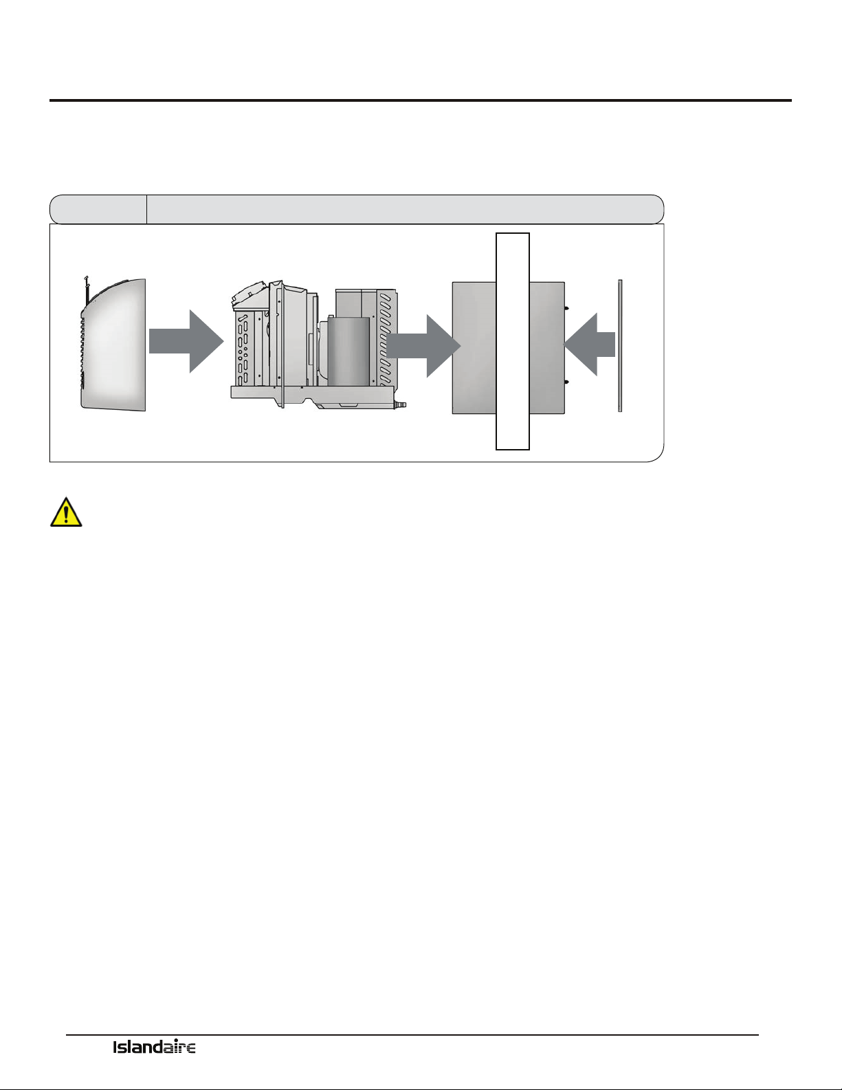
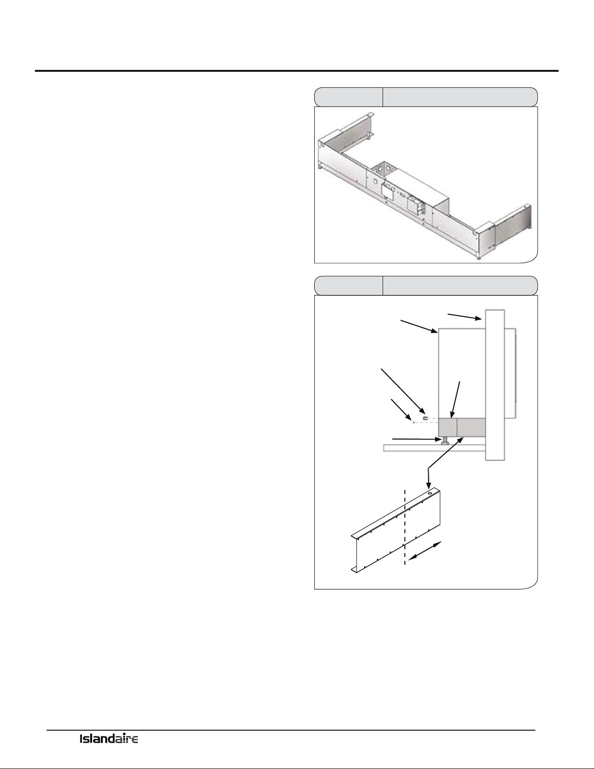
Installation Instructions
Installation of the PTAC unit involves four main components and various accessory components. e main components
are the wall sleeve, chassis, rear grille, and decorative front. e accessory components are subbase, condensate drain, duct
kits, and hardwire cable.
FRONT PANEL CHASSIS WALL SLEEVE REAR GRILLE
Figure 5 Main Installation Components
•A minimum unobstructed distance of 36” should
be kept around the outside portion of the sleeve.
•PTAC units should be installed no closer than
12” apart when two units are side by side. If three
or more PTAC units are to operate next to one
another, allow a minimum of 36” between units.
Also, a vertical clearance of 60” should be main-
tained between units.
•Units must be installed in accordance with all
applicable codes.
•Be sure that the amperage of the dedicated electri-
cal service to the unit is correct.
•e subbase accessory includes leveling legs. If
added wall sleeve support is required and a sub-
base is not to be used, an accessory leveling leg kit
may be installed.
CAUTION! To prevent damage, this unit
should NOT be operated to provide supplementary
heating and cooling during the construction period.
e unit is designed for operation in a normal indoor
environment. Operating this unit in an unenclosed
space or exposure to construction environment may
result in permanent equipment damage.
Select a location for the unit.
•Locate the unit where it will evenly distribute air
throughout the room without obstruction.
•e wall that the unit is mounted to must be a
structurally sound outside wall able to support the
weight of the unit.
•Locate the unit where there will be adequate drain-
age or access to a drain source.
•Place the unit so that the air lter can be removed
easily and maintenance work can be performed
without interference.
•Locate unit within reach of proper power supply.
Manufacturer of Quality Air Conditioning and Heating Products • www.islandaire.com • sales@islandaire.com • (800)-886-2759
18
Wall Sleeve Installation Instructions
Preparing the Wall
Opening
•Once a satisfactory location is found and height of
unit is determined, create a wall opening to install
the wall sleeve. e rough opening should mea-
sure a minimum of 16 ½” high x 42 ½” wide.
•If opening will start right at the nished oor level,
leave enough clearance for carpeting, etc. If using
a power cord, leave enough space for the cord to
exit from under the front panel.
•When a subbase is used, the opening must start
above the nished oor to match the height of the
subbase selected.
•When construction is complete, check the wall
opening to be sure the wall sleeve will slide into the
opening without obstruction.
•If installed in a concrete or masonry wall, a lintel
must be provided in the wall opening for support.
•Do not use the wall sleeve as a lintel.
•When installed in the opening, the wall sleeve
must be horizontally level from side-to-side and
pitched (one quarter bubble in the sight glass) to
the outside.
DO NOT SLOPE THE WALL SLEEVE
TOWARD THE ROOM.
•e installer must provide adequate sealing and
insulation around the sleeve aer it is installed.
•If used, a 208/230 volt wall receptacle must be
located within 58 inches of the lower right sleeve
corner. Extension cords must not be used with the
unit.
•For installations in walls deeper than 13-7/8
inches, special care is necessary to prevent prob-
lems with rain water, condensate drainage and
intake/discharge air. Consult with your Sales Rep-
resentative before attempting such installations.
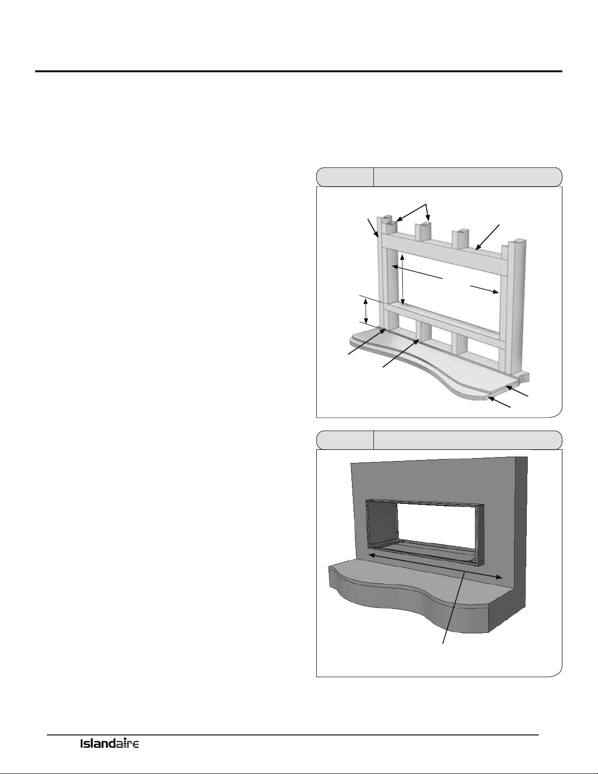
Framing
Proper building practices must be used when construct-
ing a wall opening to support a PTAC wall sleeve and
chassis. Units must be installed in accordance with all
applicable codes.
MAIN
STUD
3” FROM
FINISHED
FLOOR
CRIPPLE
JACK STUDS
16 1/2”
MIN.
HEADER - (1) 4”X 4” OR
(2) 2” X 4” ON EDGE
42 1/2”
FLOOR
JACK STUD
SUB-FLOOR
Figure 6 Framing and Minimum Wall Opening
WALL RECEPTACLE MUST BE LOCATED WITHIN 58” OF LOWER
RIGHT CORNER (208/230 VOLT UNITS ONLY)
ACCESS TO MAINS MUST BE AVAILABLE FOR ALL OTHER UNITS
Figure 7 Framing and Minimum Wall Opening
Manufacturer of Quality Air Conditioning and Heating Products • www.islandaire.com • sales@islandaire.com • (800)-886-2759
19
Wall Sleeve Installation Instructions (cont.)
Wall Sleeve Installation
Aer the wall opening is checked for location, size, and
clearances, proceed to wall sleeve installation.
1. Install Condensate Drain Kit (if applicable).
2. Slide the wall sleeve into the wall opening. e unit
chassis must t snugly and uniformly into the wall
sleeve without distortion.
3. Make sure the sleeve is within the range of minimum
projections as outlined on the next page.
4. Level wall sleeve side-to-side. When using an
INTERNAL DRAIN with this unit, it is recom-
mended to install the wall sleeve in a level position
front-to-back within the wall. If the internal drain
was to clog up from lack of maintenance, water will
still overow through the weep slots in the sleeve
near the louver and be directed outdoors. For proper
drainage, the sleeve should be level from side-to-side
and one-quarter bubble in the sight glass sloping to
the outside (if unit is to drain outside).
5. Secure the wall sleeve by anchoring with fasteners
through the sides and top. Drill holes of proper size
and in the proper location so the screws will engage
into strong supporting members of the wall. DO
NOT DRILL THROUGH BOTTOM OF WALL
SLEEVE. THIS CAN CAUSE LEAKAGE OF CON-
DENSATE WATER WITHIN THE WALLS.
6. Check the level of the wall sleeve and adjust if neces-
sar y.
7. Caulk or seal around the outside of the entire
sleeve.
8. Recycle or dispose of packaging materials per local
codes.
Note
e installer must determine and supply the
mounting bolts and/or screws to attach the
wall sleeve to the sides of the wall opening.
Make sure the wall opening is adequate for
strong support.
WALL
OPENING
WALL SLEEVE
Figure 8 Wall Sleeve Installation
MAKE SURE WALL SLEEVE IS
LEVEL SIDE TO SIDE
FRONT VIEW
FASTEN SLEEVE
TO FRAMING WITH
WOOD SCREWS AT
SIDES & TOP
DO NOT DRILL OR ATTACH SCREWS TO BOTTOM OF SLEEVE
Figure 9 Wall Sleeve Installation
SIDE VIEW
INSIDE WALL
SEE NOTE 4
Figure 10
Wall Sleeve Installation
Manufacturer of Quality Air Conditioning and Heating Products • www.islandaire.com • sales@islandaire.com • (800)-886-2759
20
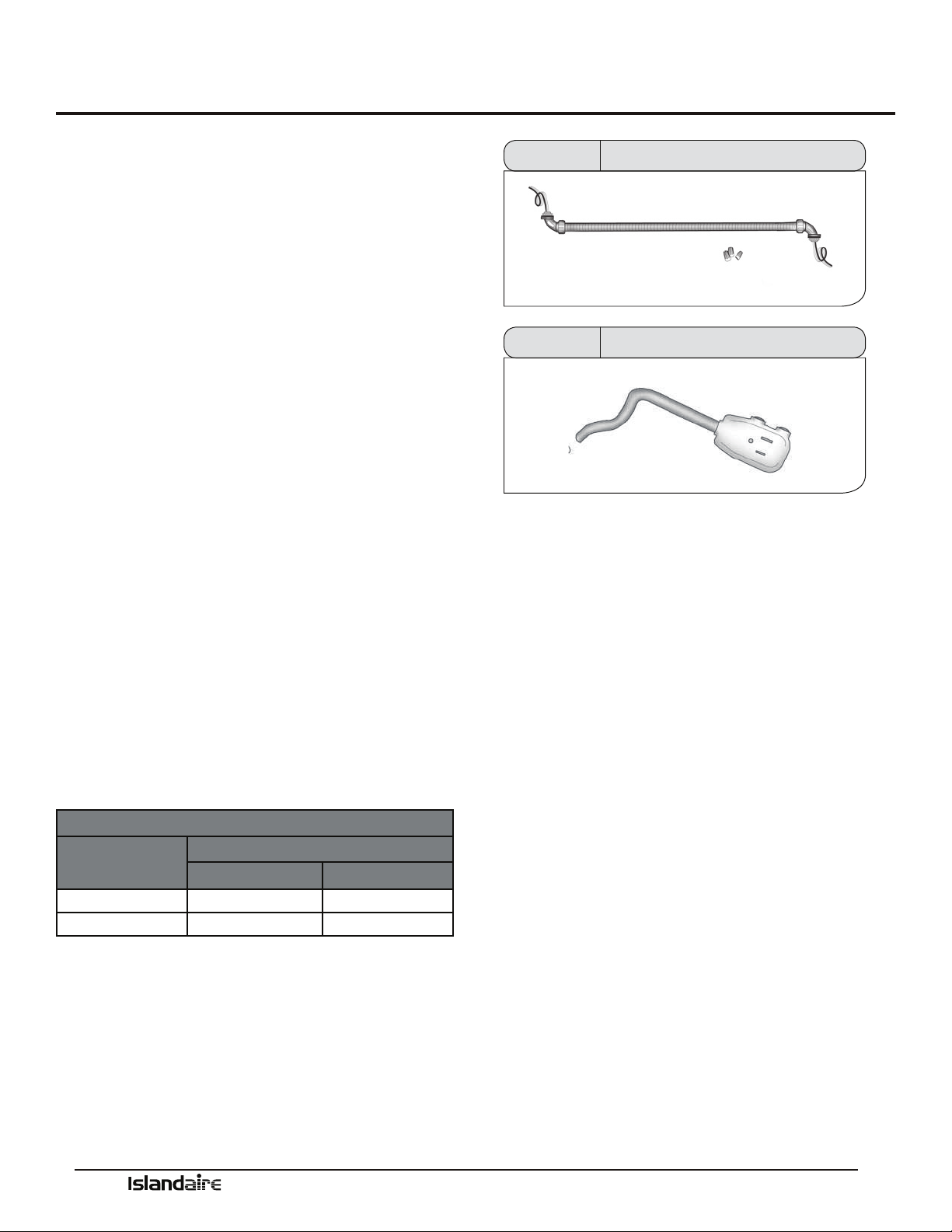
Condensate Drain Kit
Condensate Drain Kit
Part Number 4090661
An indoor/outdoor drain kit is available as an accessory
item. When a drain kit is to be installed, do so before
installing the wall sleeve in the wall.
During periods of high humidity and/or during heat
pump operation condensate water will collect in the bot-
tom pan of the chassis. When the chassis bottom pan is
full, the water will overow into the wall sleeve and out
the drainage holes on the back edge of the wall sleeve.
e Condensate Drain kit contains an overow tube to
direct excess condensate water from the bottom of the
sleeve to either an internal or external drainage path.
Because heat pumps generate condensate even during
the heating season, it is recommended to always use a
drain kit with heat pump models. Determine whether
the kit should be installed as an internal or external drain
system.
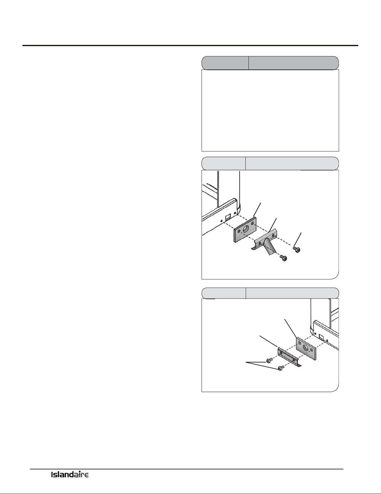
External Drain
Installation
Part Number 6140165
e drain kit can be installed as an external drain on the
le or right side drain opening on the sleeve. Determine
which drain opening will provide the best drainage for
the installation.
Local codes will determine the proper method for con-
densate disposal. e drain kit must be installed before
installation of the wall sleeve condenser grille.
1.
Remove the cardboard weather board from the
wall sleeve.
2. Install the outdoor drain tting and one of the
outdoor drain tting gaskets over one of the
drain holes on the rear of the wall sleeve. Secure
this assembly to the rear of the sleeve with two
sheet metal screws into the holes provided in the
wall sleeve.
3. Cover and seal the remaining drain hole using
the remaining outdoor drain gasket, cover plate
and remaining sheet metal screws provided.
Periodically inspect drain passages for blockage. Blow
out drain tubing annually to prevent overow from
entering the building.
NOTE
is drain kit serves only as a link between the
unit and eld-supplied condensate drain system.
Installing the kit without connecting it to
a drainage system will result in inadequate
condensate removal, possible leakage and
corrosion.
OUTDOOR
GASKET
OUTDOOR
DRAIN
FITTING
SHEET
METAL
SCREWS
Figure 11 External Drain Installation
BLOCK-OFF
PLATE
SHEET
METAL
SCREWS
OUTDOOR
GASKET
INSTALL BLOCK-OFF PLATES
AND GASKETS OVER LEFT AND
RIGHT EXTERIOR DRAIN HOLES
Figure 12 Block-Off Plate Installation
Manufacturer of Quality Air Conditioning and Heating Products • www.islandaire.com • sales@islandaire.com • (800)-886-2759
21
Condensate Drain Kit (cont.)
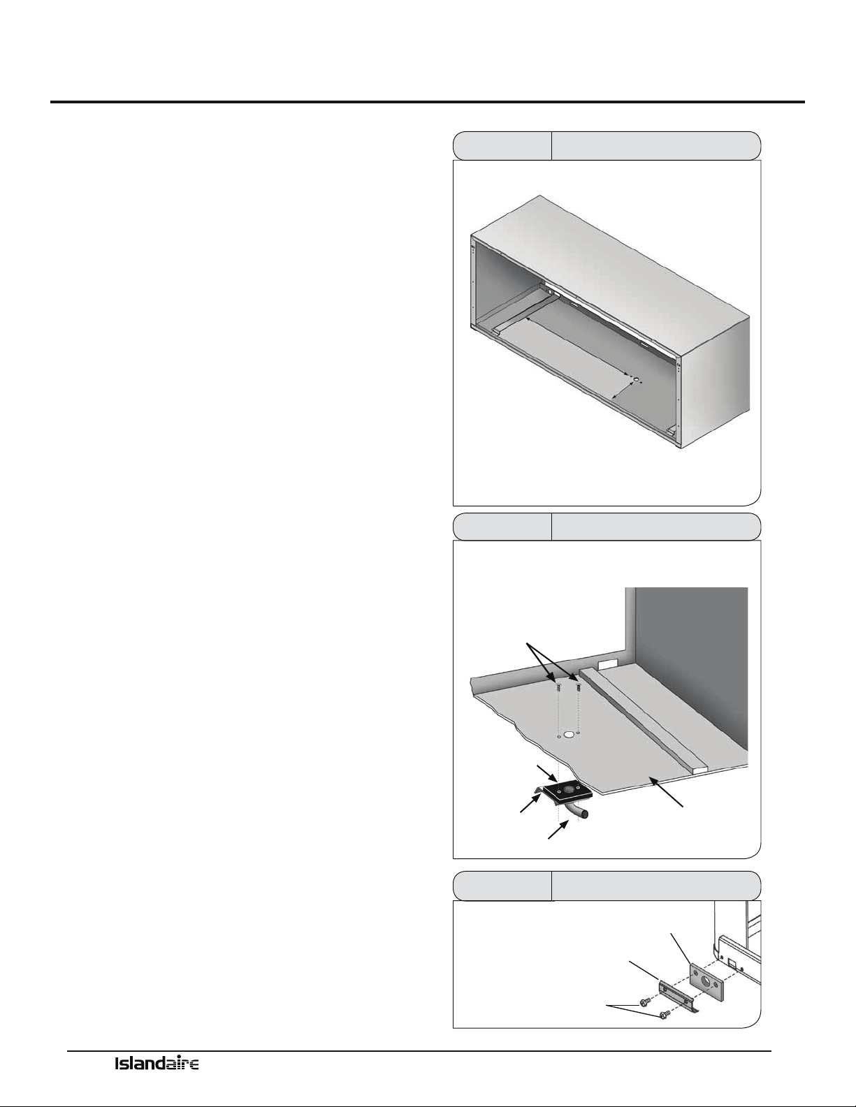
Internal Drain
Installation
Part Number 6140165
e drain kit can be installed as an internal drain on the bot-
tom of the wall sleeve to allow condensate to drain into an
internal drain system inside of the building. Locate the drain
so that it will be on the room side of the wall when the cabinet
wall sleeve is installed.
NOTE: e drain kit must be installed prior to the installation
of the wall sleeve.
1.
Locate an area on the wall sleeve that will be inside
the room when the sleeve is installed. If a subbase
is installed, locate the kit a minimum of 5 ½” from
the front ange of the wall sleeve. is clearance will
provide adequate clearance for the subbase.
2. Cutout the template shown to the right. Using this
template, locate and drill the drain kit holes as close
to the outside wall as possible.
3. Using detail gure 13 as a guide, assemble the drain
gasket, drain tting plate, and indoor drain tting
together. Install the assembly into the drilled holes
and secure using the two indoor mounting screws
provided. e screws must be inserted INSIDE the
wall sleeve and TOP driven down into the drain t-
ting plate.
Ensure drain tube is not restricted. Cover the two screw heads
with a good quality outdoor caulking (not supplied) for addi-
tional corrosion protection.
NOTE: If the drain tting is not connected to an indoor
drainage system immediately aer the wall sleeve is installed,
plug the hole with cork (not included) to prevent indoor water
damage in case it rains.
4.
Install a ½” ID tube or hose (not included) on the
drain tting and interconnect it to the drain system
inside of the building. Ensure that there are no kinks
or traps in tube or hose. Kinks or traps can cause
improper drainage.
5. Install the two drain block-o plates and outdoor
drain gaskets on the outdoor portion of the wall
sleeve as shown in gure 15. ese components can
be installed aer the sleeve is secured in the wall
opening just prior to the installation of the condenser
grille and chassis.
DRAIN LOCATION FROM SIDE-
TO-SIDE IS DETERMINED BY
BUILDING DRAIN SYSTEM
DRAIN LOCATION FROM FRONT EDGE OF WALL
SLEEVE SHOULD BE A MIN. OF 5.5 INCHES IF
USING SUBBASE
DETERMINE LOCATION OF
INTERNAL DRAIN.
DRILL MOUNTING HOLES
ACCORDING TO TEMPLATE
Figure 13 Internal Drain Location
ATTACH DRAIN FITTING, GASKET, AND PLATE WITH SCREWS
INSERTED THROUGH WALL SLEEVE
SHEET METAL
SCREWS
GASKET
PLATE
DRAIN FITTING
INSIDE OF WALL SLEEVE
Figure 14 Internal Drain Installation
BLOCK-OFF
PLATE
SHEET
METAL
SCREWS
OUTDOOR
GASKET
INSTALL BLOCK-OFF PLATES
AND GASKETS OVER LEFT AND
RIGHT EXTERIOR DRAIN HOLES
Figure 15 Block-Off Plate Installation
Manufacturer of Quality Air Conditioning and Heating Products • www.islandaire.com • sales@islandaire.com • (800)-886-2759
22
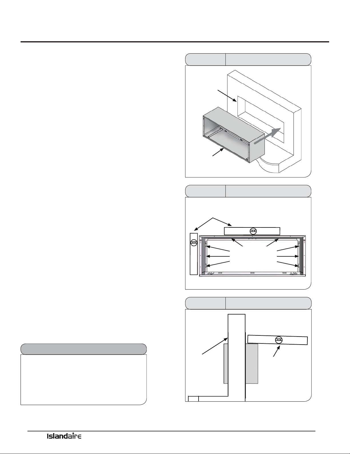
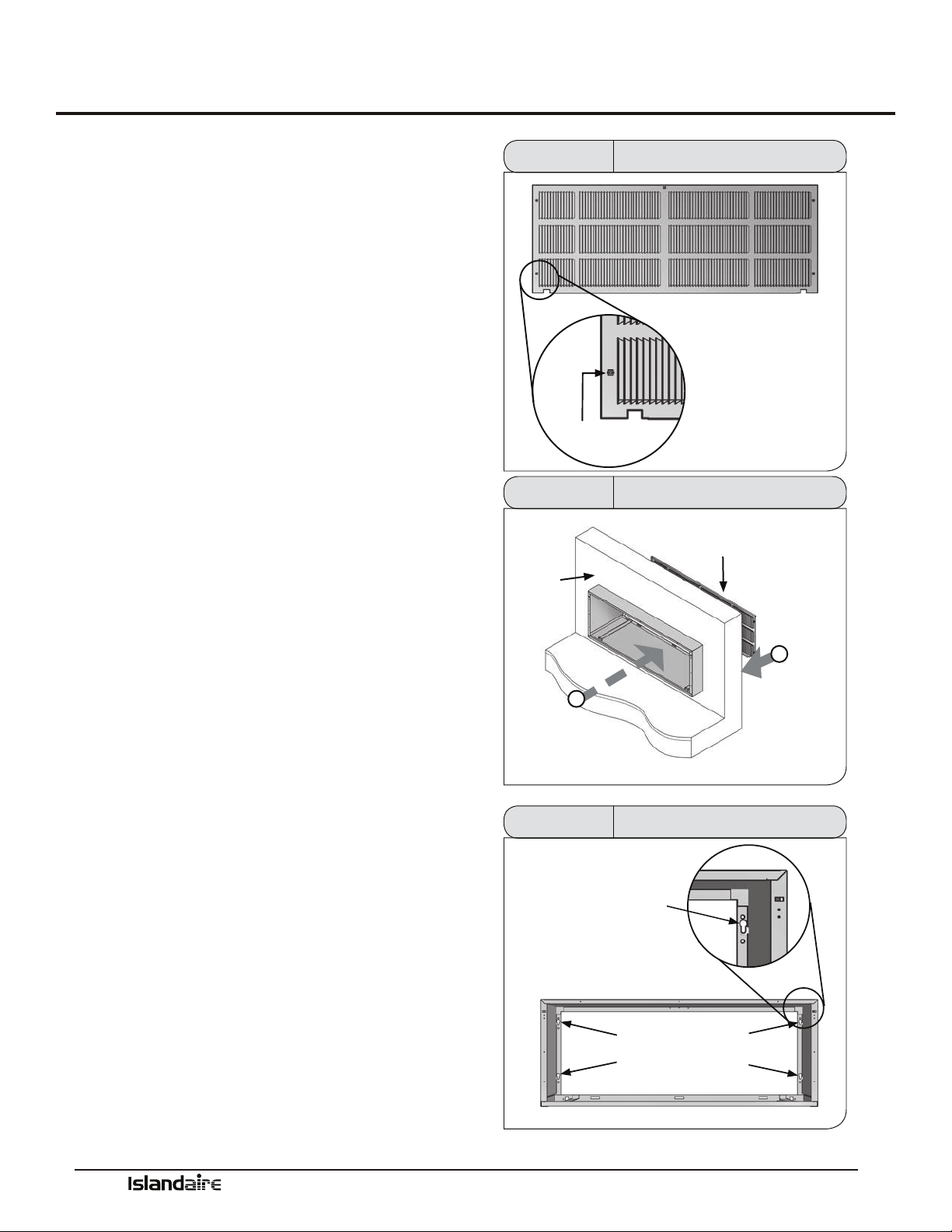
Rear Grille Installation Instructions
Stamped Rear Grille
Part Number 6070264
e rear grille directs condenser airow and provides
a protective barrier for the outdoor coil. Either the
approved Standard or Architectural grille must be
installed before installing the chassis.
STANDARD LOUVERED GRILLE INSTALLATION
1. Prepare the grille for installation by installing the ve
plastic fasteners supplied through the holes in the
grille.
2. Guide the alignment pins, located on the lower-right
and lower-le hand corners of the grille, with their
corresponding holes on the rear outside edge of the
wall sleeve.
If installing the grille from inside the room:
Use the attached plastic handle to keep a rm grasp
on the grille. Angle the grille through the opening at
the rear of the wall sleeve, then pull the grille back to
the wall sleeve and align the screw heads to the hole.
Be sure to keep a rm grip on the plastic handle and
grille to prevent it from dropping and/or causing pos-
sible injury or property damage. Remove the plastic
handle when installation is complete.
3. Secure the grille to the wall sleeve by installing
screws into the plastic fasteners. Be careful not to
damage fasteners by overtightening.
PLASTIC
FASTENER
STANDARD GRILLE
Figure 16
Standard Grille Fastener
INSIDE
WALL
1
ANGLE THE GRILLE
THROUGH THE OPENING AT
BACK OF WALL SLEEVE
2
PULL FORWARD
TO INSERT SCREW
HEADS INTO
KEYHOLE SLOTS
STANDARD
GRILLE
Figure 17 Standard Grille Installation
SECURE THE GRILLE TO THE WALL
SLEEVE BY TIGHTENING SCREW
HEADS IN HOLES.
DO NOT OVERTIGHTEN
HOLES
WALL SLEEVE
Figure 18 Standard Grille Installation
Manufacturer of Quality Air Conditioning and Heating Products • www.islandaire.com • sales@islandaire.com • (800)-886-2759
23
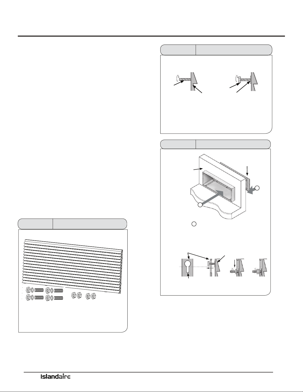
Rear Grille Installation Instructions (cont.)
Architectural Rear
Grille
Part Number 6070422
e rear grille directs condenser airow and provides
a protective barrier for the outdoor coil. Either the
approved Standard or Architectural grille must be
installed before installing the chassis.
ARCHITECTURAL LOUVERED GRILLE KIT INSTALLATION
1. Install the four threaded studs into the threaded
openings on the inside face of the grille. Install a
washer and one hex nut to the end of each stud.
2. Manipulate the grille out through the rear wall sleeve
opening. Be sure to keep a rm grip on the grille
to prevent it from dropping and/or causing possible
injury or property damage.
3. Attach the grille to the sleeve by aligning and insert-
ing the hex nut threaded onto the studs through the
holes in the wall sleeve.
4. Secure the grille to the sleeve by tightening the hex
nut and adding and tightening an additional hex
nut.
Figure 19 Architectural Rear Grille Parts
STUD
HEX NUT
WASHER
ARCHITECTURAL
GRILLE
INSTALL THE FOUR THREADED STUDS INTO THE THREADED
OPENINGS ON THE INSIDE FACE OF THE GRILLE. INSTALL WASHERS
AND HEX NUTS TO THE END OF EACH STUD.
Figure 20 Threaded Stud Installation
1
2
INSIDE
WALL SLEEVE
“KEY” HOLES
ARCHITECTURAL
GRILLE
ARCHITECTURAL
GRILLE
2
PULL FORWARD TO GUIDE HEX NUTS
THROUGH HOLE IN WALL SLEEVE, THEN
TIGHTEN HEX NUTS. SECURE WITH AN
ADDITIONAL HEX NUT.
ANGLE THE GRILLE
THROUGH THE OPENING
AT BACK OF WALL SLEEVE
Figure 21 Arch. Rear Grille Installation
Manufacturer of Quality Air Conditioning and Heating Products • www.islandaire.com • sales@islandaire.com • (800)-886-2759
24
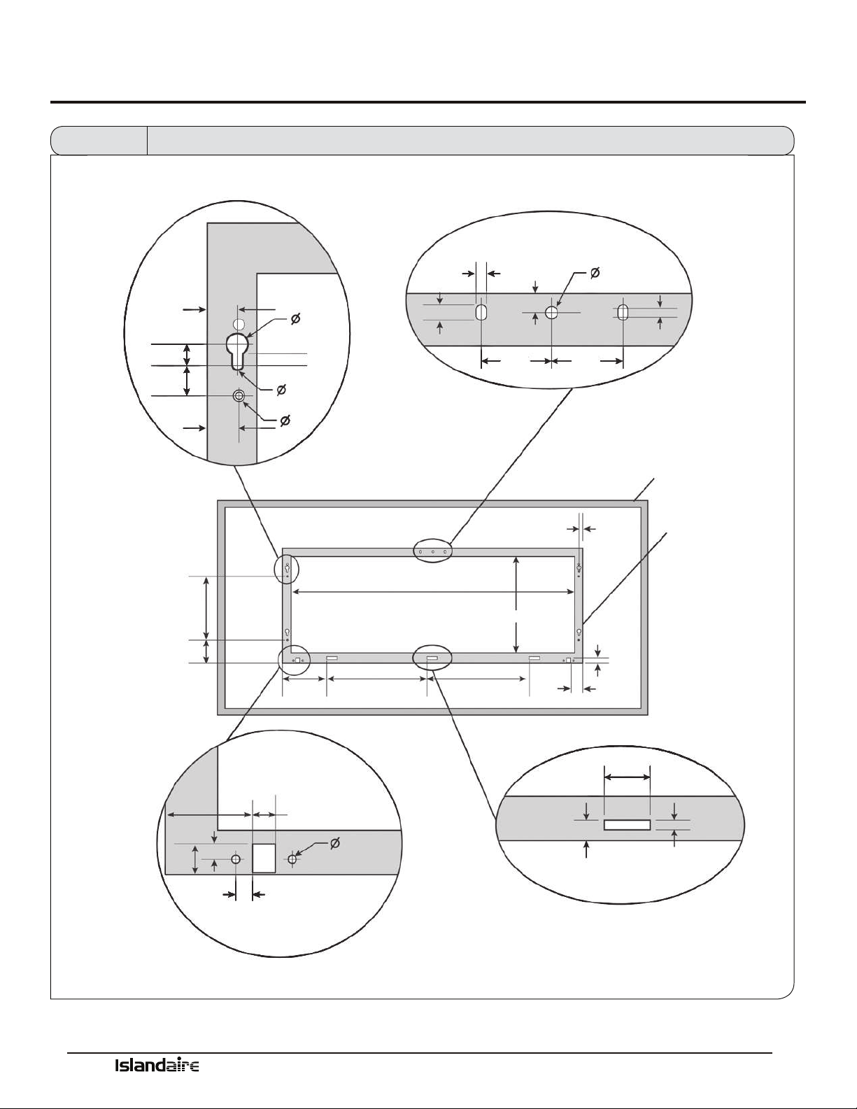
Rear Grille Installation Instructions (cont.)
TYPICAL HOLE &
MOUNTING STUD LOCATION
UPPER MOUNTING HOLES
LOCATION & DIMENSIONS
WINDOW FRAME
(LOUVERS NOT SHOWN)
WALL SLEEVE
STUD LOCATION
(CENTER TO CENTER)
CONDENSATE DRAIN LOCATION
LOWER SLOT DIMENSIONS
& LOCATION (TYP.)
.688
.500
.444
.725
.227
.250
.725
.250
.218
.375
.450
.250
1.525 1.525
.079
.725
.9.000
39.750 I.D.
13.887 I.D.
.700
3.150
6.175 14.075 14.075
1.919
.700
1.919
.350
.369
(X2)
.512
.187 (X2)
.400
1.500
.313
Figure 22 Wall Sleeve Dimensions and Mounting Hole Locations for Installation of Exterior Louver Grille by Others
Manufacturer of Quality Air Conditioning and Heating Products • www.islandaire.com • sales@islandaire.com • (800)-886-2759
25
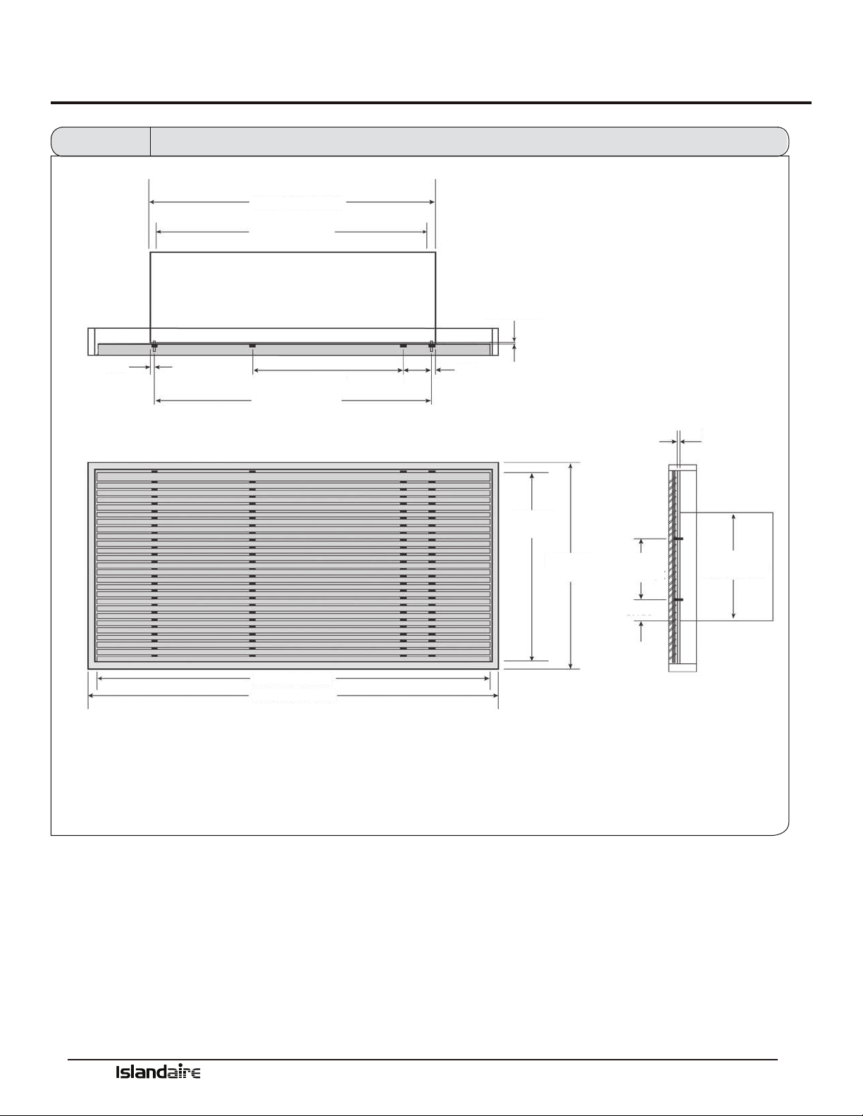
Rear Grille Installation Instructions (cont.)
42.00 PTAC WIDTH
39.75 PTAC I.D.
.125
SHEET METAL
THICKNESS
.125
SHEET METAL
THICKNESS
LOUVER
HEIGHT
WINDOW
HEIGHT
LOUVER WIDTH
WINDOW WIDTH
16.06
PTAC HEIGHT
9.000
STUDS C/C
3.150
STUDS C/C 40.55
.725
27.00
4.75
.725
Figure 23
Wall Sleeve Dimensions and Mounting Stud Locations for Installation of Exterior Louver Grille by Others
Manufacturer of Quality Air Conditioning and Heating Products • www.islandaire.com • sales@islandaire.com • (800)-886-2759
26
Subbase Assembly & Installation
Subbase Assembly &
Installation
ELECTRICAL SUBBASE ASSEMBLY
An electrical Subbase provides a convenient location for
unit wiring to be connected to building wiring. It also
provides support for the indoor portion of the unit.
SUBBASE SELECTION
Select a subbase according to the power requirements of
the unit. See Subbase Selection chart on page 27.
SUBBASE ELECTRICAL CONNECTION
e wiring should be roughed in and the conduit con-
nected to the subbase junction box. Complete the instal-
lation by wiring the receptacle to the incoming power
supply.
Subbase Installation Notes:
1. Insert the side extension pieces into the front assem-
bly and determine the required assembly depth by
placing the assembly under the wall sleeve.
2. Determine the depth of the side extension pieces
desired and cut at the proper depth. Subbase may be
installed without the side extension pieces.
3. Insert leveling bolts into the subbase bottom ange.
Four (4) bolts are required if the side extensions are
used.
4. Place the subbase on the oor and align its center
line with the center line of the wall opening.
5. Secure the subbase to the wall sleeve with the two
retainer clips provided.
Figure 24 Assembled Subbase
WALL SLEEVE
RETAINER
CLIP
SIDE EXTENSION:
TRIM TO FIT
SUBBASE
CUT AT PROPER DEPTH AND
DISCARD EXCESS
WALL
RETAINER
SCREW
LEVELING
BOLTS
Figure 25 Subbase Installation

Manufacturer of Quality Air Conditioning and Heating Products • www.islandaire.com • sales@islandaire.com • (800)-886-2759
27
Subbase Assembly & Installation (cont.)
SUBBASE PARTS LIST
10
13
11
1
9
5
10
4
6
13
7
14
2
3
8
12
SUBBASE SELECTION CHART
TYPE
EZSB - Sub Base
EZSB 42 05 BP R12 S00 F15 V01
HEIGHT
03 - 3”
04 - 4”
05 - 5”
06 - 6”
07 - 7”
08 - 8”
09 - 3”
10 - 10”
ELECTRICAL MODULE
BP - Blank Plate (Non-electrical)
EM - With Module for Electrical Kits
SWITCH/CIRCUIT BREAKER KIT
S00 - None
S30 - Disconnect Switch
FUSE KIT
F00 - None
F15 - 15 Amp Fuse
F20 - 20 Amp Fuse
F30 - 30 Amp Fuse
LOW VOLTAGE CONNECTIONS KIT
V00 - None
V01 - Low Voltage Connections
MODEL TYPE
16 - Amer. Air Filter 16
25 - Amer. Air Filter 25
40 - Amer. Standard SR40
41 - Amer. Standard TW41
42 - Islandaire 42 x 16
45 - Amer. Standard 45
5R - Ice Cap 5R
61 - Climate Mstr. 801
8S - Climate Mstr. 801 Small
AD - Friedrich CM700
C7 - Friedrich CM701
C8 - Friedrich CM180
CC- Slant Fin CC
CH - Chromalox Up/Down
Flow
CK - Zoneaire Climette/Kee-
prite (Flat)
CM - Climate Mstr.
702/703/704
CS - Zonaire Climette/Kee-
prite (Slope)
CX - Chormatox CAM
CY - Chrysler/Nesbit
EB - Singer/McQuay EB
EC - Singer/McQuay EC
ED - Singer/McQuay EA/RS
EH - McQuay HC/EMEK
Singer KS (EK)
ET - Friedrich ET
FM - Slant-Fin Monterey
GE - GE Flat Top
GS - Islandaire Gas/LP PTAC
G3 - Islandaire 38” Gas PTAC
HP - AAF HP/Singer CC
HW - AAF HW/Singer CC
HQ - Hell Quaker SEA
IT - Integrity
JA - Singer/McQuay J
JK - Slant-Fin JK Up/Down Flow
KF - Singer/McQuay K
LM - Singer/McQuay LM
MX - Fedders Maxizone
N3 - Dunham-Bush Newport III
N4 -Dunham-Bush Newport IV
NC - Nesbitt Challenger
NE - McQuay N/Carrier 42 x 16
NR - Nesbitt Roomate
NY - Islandaire 42 x 16
(Hydronic)
PT - Lennox PTEIA
RB - Westinghouse RB
RK - Icecap RSK
RM - Zonaire RM
RT - Ice Cap RSC
UN - Fedders Unizone
VF - Singer/McQuay Vertical
Water Source
WC - Cool Heat WCC-6
WH - Friedrich 800
WL - Ice Cap WL
WM - Singer/McQuay WM
REPLACEMENT KIT
R00 - None
R01 - Perm. Connection BX
R12 - 208/230V 15/20A
R13 - 208/230V 30A
R14 - 277V 15A
R15 - 277V 20A
R16 - 277V 30A
R17 - 115V 15/20A
ITEM
1
2
3
4
5
6
7
8
9
10
11
12
13
14
QTY
1
1
1
1
1
1
1
1
2
4
4
2
4
DESCRIPTION
BASE FRAME
REAR COVER
JUNCTION BOX COVER
RH SIDE EXTENSION
LH SIDE EXTENSION
RECEPTACLE SUPPORT
REAR COVER PANEL
JUNCTION BOX
1
FRONT PANEL
RECEPTACLE PANEL
RECEPTACLE PANEL
LINE CORD GUARD
ATTACHMENT CLIP
LEGS
Figure 26 Subbase Nomenclature
Manufacturer of Quality Air Conditioning and Heating Products • www.islandaire.com • sales@islandaire.com • (800)-886-2759
28
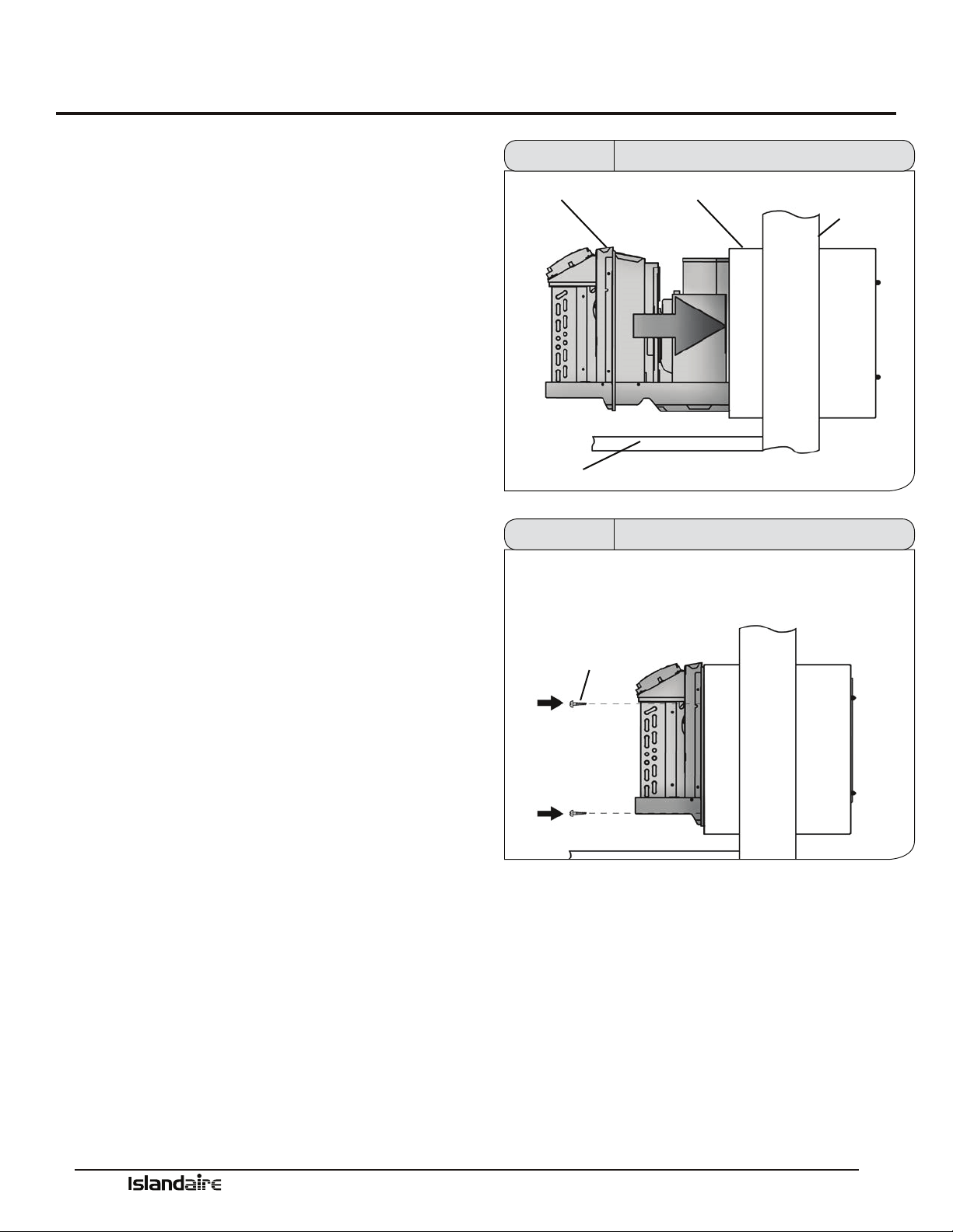
Chassis Installation
1. Remove the cabinet front from the chassis as
described in Front Removal.
2. Insert the chassis into the wall sleeve.
3. Slide the chassis into the wall sleeve until the
chassis anges contact the front edge of the wall
sleeve.
4. Secure the chassis to the wall sleeve using two
screws on each side of the chassis to ensure a
proper seal between the chassis and the wall
sleeve.
CHASSIS
FLOOR
WALL SLEEVE
EXTERIOR
WALL
Figure 27 Chassis Installation
SHEET METAL
SCREWS
Figure 28 Chassis Installation
Manufacturer of Quality Air Conditioning and Heating Products • www.islandaire.com • sales@islandaire.com • (800)-886-2759
29
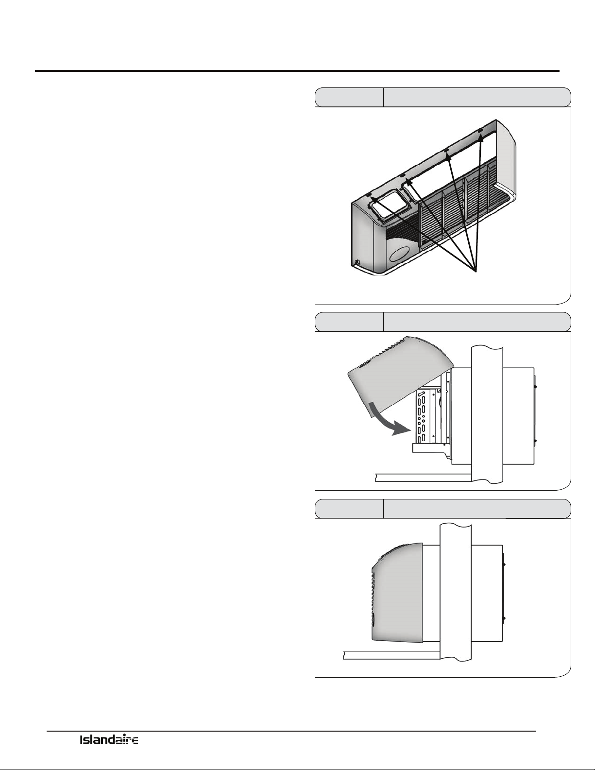
Front Cover Installation & Removal
Use the following procedure to install the front panel
onto the chassis:
1. Attach the top of the front cover onto the top edge of
the chassis.
2. Swing down the front cover over the chassis and
apply pressure until it locks into place.
3. Make sure that digital display opening and lters
align with proper locations on chassis.
Front Cover Removal
Remove the front cover by pulling out at the bottom to
release it, then li it up to clear the rail along the chassis
top.
TABS
Figure 29 Front Cover Tabs
Figure 30 Front Cover Installation
Figure 31 Front Cover Installation

Manufacturer of Quality Air Conditioning and Heating Products • www.islandaire.com • sales@islandaire.com • (800)-886-2759
30
Fresh Air Vent
Fresh Air Vent
e vent control allows outside air to be drawn into the
conditioned area. is outside air can provide ventila-
tion when the blower is operating, but it will increase the
heating or cooling load and operating costs.
To obtain access to the vent control:
1. Remove the cabinet front (see Front Removal).
2. Remove the shipping screw (if installed) from the
vent door.
3. Remove the label (if present) from over the vent con-
trol lever on the le side of the chassis. Remove the
vent door shipping screw.
NOTE: Recommended for use on models with remote
thermostat. Not recommended for models with built-in
thermostats.
Lateral Duct Kit
e Lateral Duct kit allows the air from one PTAC unit
to be shared by an adjacent room. e kit mounts to the
top of the unit and can be congured for either right or
le discharge. e amount of air diverted to the second
room is adjustable.
Figure 32 Fresh Air Vent
e kit consists of a main duct for the room of origin
and an extension duct to reach the adjoining room and
terminal duct.
Part Number 4082401 Main Duct with Transition
Part Number 4082404 Duct Extension
Part Number 6070199 End Grille
FINISHED
FLOOR
6-7/16”
9-13/32”
2-31/32”
16”
3” MIN
6-15/16”
TRANSITION
ROOM CABINET
13-1/4”
MAX
1” MIN WALL TO
SLEEVE EDGE
WALL SLEEVE
DUCTED EZ42 DETAILED SIDE VIEW
Figure 33 Lateral Duct Kit
Installing Air Discharge
Package
is original package allows for distribution of air into an
adjacent zone requiring a controlled temperature. is
assembly will discharge the conditioned air to either the
right or le depending upon which end the end cap is
placed. Total overall length of duct kit not to exceed 10
feet.
Manufacturer of Quality Air Conditioning and Heating Products • www.islandaire.com • sales@islandaire.com • (800)-886-2759
31
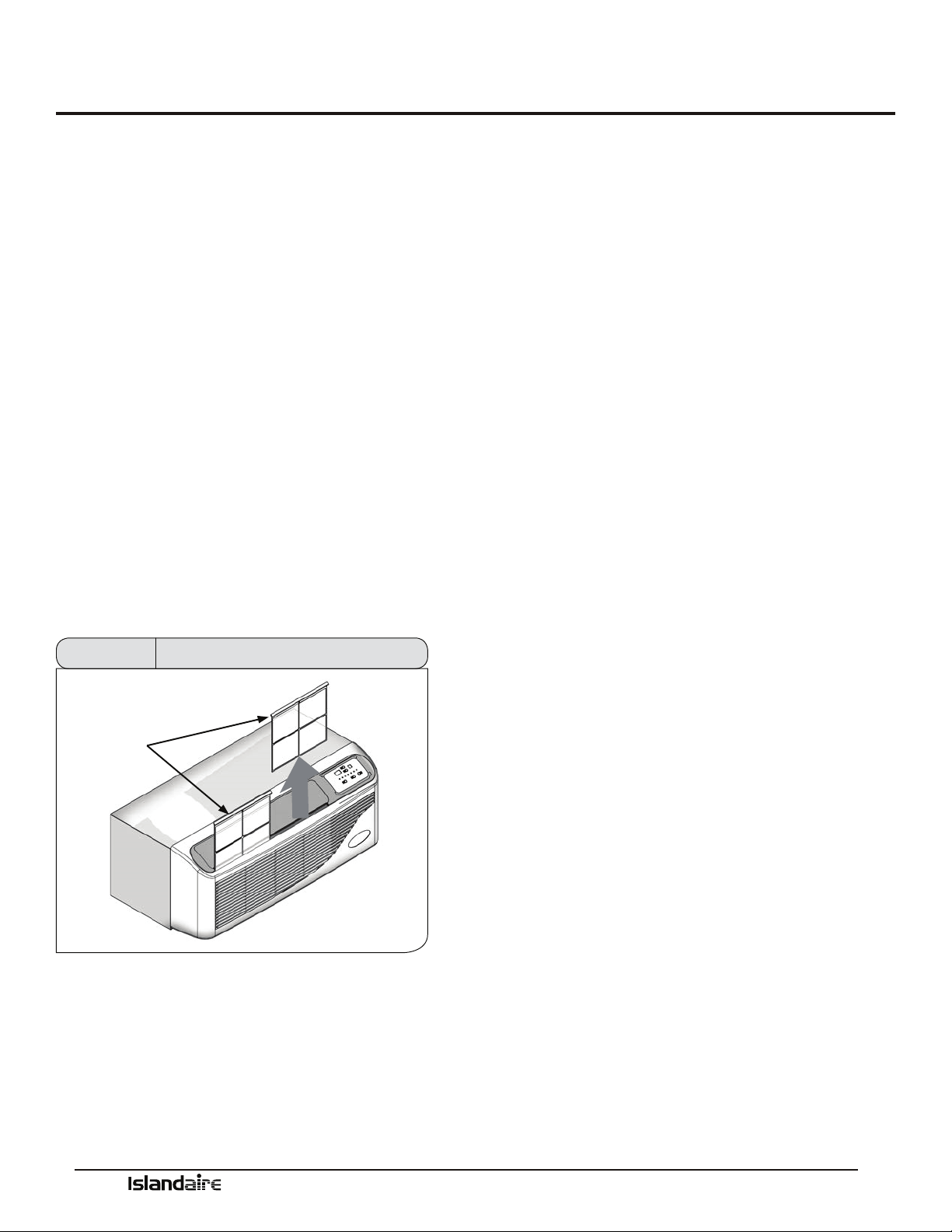
Maintenance
Air Intake Filters
(2 per) Part Number 6080067
When the air conditioner is operating, indoor air is l-
tered and reltered continuously trapping airborne dirt
and dust in the washable lter. e air intake lters
are removable for easy cleaning. A clean lter helps
remove dust, lint, and other particles from the air and
is important for best cooling and operating eciency.
Check the lter every two weeks to see whether it
needs cleaning.
1. Turn unit o.
2. Remove each air lter by grasping the top edge of
the lter frame and pulling each one up and out of
the unit.
3. Wash in hot soapy water, rinse and shake dry.
4. Replace the lter, with the front of the lter toward
you.
5. To dry the lter thoroughly, run your unit for a few
minutes in fan mode.
AIR INTAKE
FILTERS
Figure 34 Filter Removal
Routine Maintenance
Keep air intake lter clean.
•Coils should be inspected periodically for build-up
of lint, dirt, leaves, other debris, and bent ns.
•Clean coils with a so brush and compressed air or
vacuum. Do NOT use sharp objects to clean coils.
•e fan motors are permanently lubricated and do
not require servicing.
•In areas of heavy snow and ice accumulation,
snow and ice should not be permitted to accu-
mulate against the unit. As soon as practical aer
such inclement weather, clean snow and ice from
around the unit as much as possible.

Manufacturer of Quality Air Conditioning and Heating Products • www.islandaire.com • sales@islandaire.com • (800)-886-2759
32
Information for Heat Pump units
Heat pump models oer substantial savings over models
with conventional electric resistance heaters.
Islandaire’s PTAC units provide indoor comfort in the
same manner as conventional air conditioners, removing
heat and humidity from indoor air. e heat and humid-
ity is released to the outdoors. Islandaire’s high eciency
design saves energy and reduces cooling costs.
When the outdoor coil temperature is above 20 °F
(approximately 35 °F outdoor-air temperature), the heat
pump draws heat from outdoor air and uses it to heat
indoor air. Since heat is transferred and not produced,
the heat pump uses less electricity and reduces energy
costs signicantly.
If the outdoor coil temperature falls below 20 °F (approx-
imately 35 °F outdoor-air temperature), the unit auto-
matically switches on a built-in electric heater. e com-
pressor stops and a blower circulates warm air produced
by the heater. When the outdoor coil temperature rises
above 40 °F, heat pump operation resumes automatically.
Heat Pump Features
OUTDOOR THERMOSTAT:
During the heating cycle, the outdoor thermostat senses
outdoor coil temperature. It switches the unit to electric
heat mode when the outdoor coil temperature is 20 °F or
below (approximately 35 °F outdoor-air temperature).
e thermostat switches the unit back to heat pump
mode when the outdoor coil temperature rises above 40
°F, which is enough to provide heat to meet demand. e
entire operation is completely automatic.
REVERSING VALVE:
e reversing valve controls the direction of refrigerant ow
for both heating and cooling functions and remains ener-
gized as long as the controls are in the heat position. When
the cooling controls are activated, the valve automatically
reverses to the cooling position.
NOTE: Be sure to connect reversing valve wiring to the
B (blue wire) connection of the thermostat for heat pump
applications.
Manufacturer of Quality Air Conditioning and Heating Products • www.islandaire.com • sales@islandaire.com • (800)-886-2759
33
Electrical Installation
Hardwire Kit
Part Number 6040756
Cord connection to a wall socket is not permitted for 265
volt units. All 265 volt units must be hard-wired using
the hard wire kit or make use of the plug-in receptacle in
the standard subbase.
LCDI Cords
230/208V units are equipped with LCDI or AFCI power
cords and can open the electrical circuit to the unit. In
the event the unit does not operate, check the reset but-
ton located on or near the head of the power cord as part
of the normal troubleshooting procedure.
PTAC Wire Harness Kit
See PTAC Wire Harness Kit Installation Instructions
for proper wire orientation and location for low voltage
wiring.
Heaterless Units
Refer to the Installation Instructions supplied with the
kit for a complete description of the installation proce-
dures. All 208/230 volt heaterless units are shipped with
a 15 Amp
power cord.
Voltage Measurements
Once the unit is properly wired, measure the unit
supply voltage. Voltage must fall within the voltage utili-
zation range as shown in the table below.
OPERATING VOLTAGE
UNIT VOLTAGE
RATING
VOLTAGE UTILIZATION RANGE
MINIMUM MAXIMUM
230/208 197 253
265 238 292
Figure 35 Hardwire Kit
Figure 36 LCDI Cord
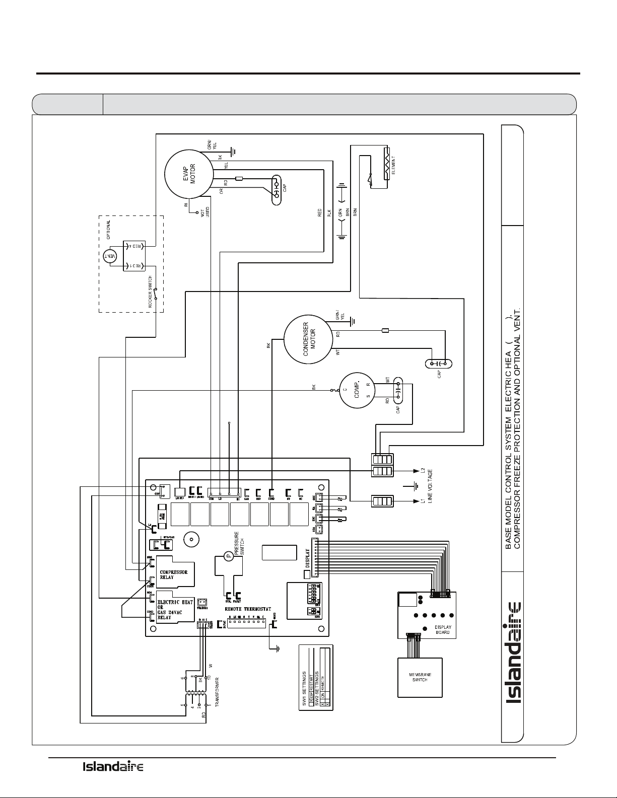
Manufacturer of Quality Air Conditioning and Heating Products • www.islandaire.com • sales@islandaire.com • (800)-886-2759
34
Wiring Diagram
RD
Y
WT
WHITE
NOT USED
BLUE
BLACK
HYDRONIC
HEAT PUMP
ELECTRIC HEAT
GAS HEAT
FREEZE PROT
RESTART
WSHP
LIMIT & FUSIBLE LINK
EZ42
YELLOW
REMOTE
WSHP
Figure 37 Wiring Diagram
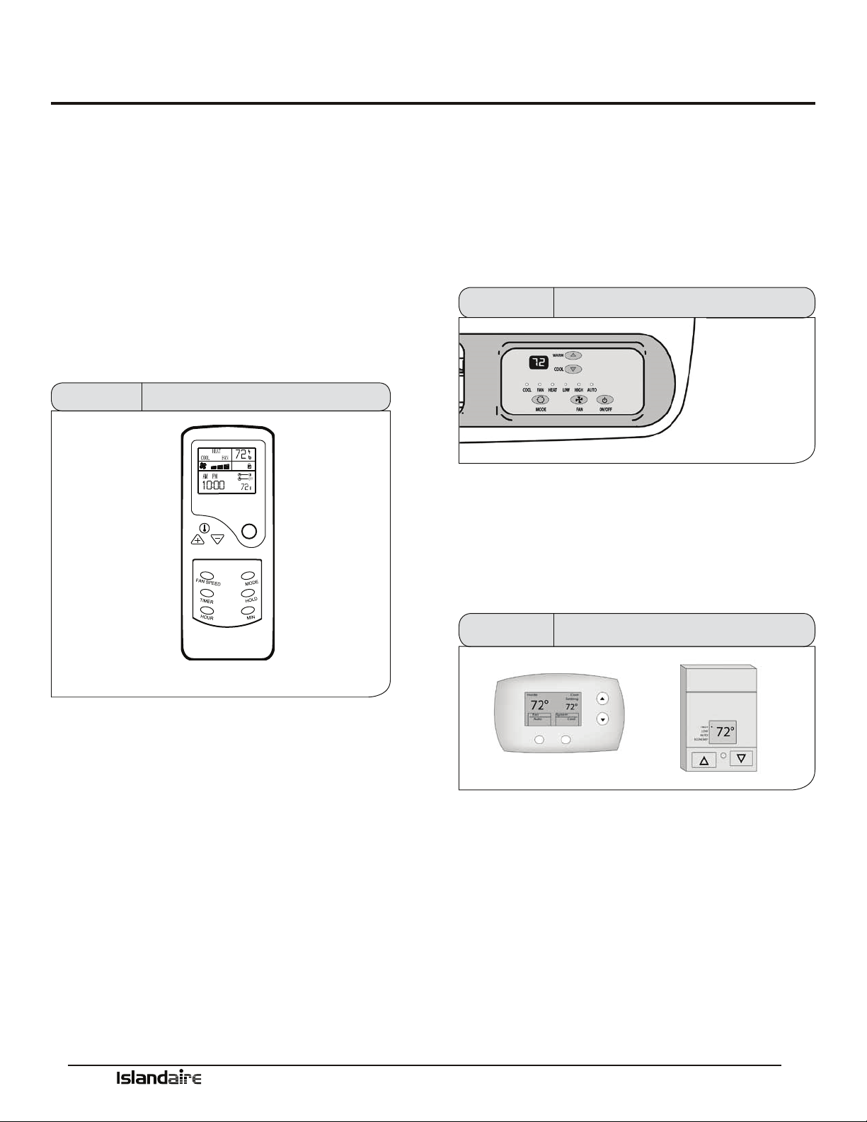
Manufacturer of Quality Air Conditioning and Heating Products • www.islandaire.com • sales@islandaire.com • (800)-886-2759
35
System Controls and Management
User Interfaces
e Islandaire PTAC can be operated by several dier-
ent control systems. Listed on this page are some of the
important control features and a brief description of their
functions.
Remote Control
Part Number 6040694 - Fahrenheit
6040806 - Celsius
e unit can be conveniently operated with a battery
operated wireless remote control. All functions are
accessible through the remote control unit.
ON/OFF
MODE INDICATOR
FAN SPEED INDICATOR
CLOCK
TEMP
FAN SPEED SET
TIMER SET
HOUR ADJUST
TEMP INDICATOR
LOCK INDICATOR
TIMER DISPLAY
POWER
MODE
HOLD
MIN ADJUST
TIMER
Figure 38 Remote Control
GENERAL OPERATION
Press the On/O button on the remote control.
Press the MODE button to select the desired operation
mode: Cool/Fan/Heat. Press the TEMP + or TEMP -
buttons to set desired temperature. Press the Fan Speed
button to set the desired air ow rate (high/med/low).
Setting the Clock
When new batteries are inserted, the default clock setting
is 00:00 A.M. To adjust the setting to the current time,
open the back cover and push the CLK button; the clock
display will blink. Use the HOUR and MIN buttons to
set the current time. en press the CLK button again
and close the back cover.
Digital Control Panel
e built-in digital control panel features an easy to
read digital display, large buttons and bright indicator
lights. Energy management and temperature limiting
preferences allow the owner to increase eciency, limit
extreme usage and optimize performance.
See page “Digital Control Panel” on page 37 for full details
Figure 39 Digital Control Panel
Wall Thermostats
Terminal connections on the main control board allow
easy conversion from an on-board control panel to a wall
mounted thermostat control (wired or wireless).
See page “Remote Thermostats” on page 39 for full details
Figure 40 Wall Thermostats
Front Desk Control
Low voltage terminals on the main control board allow
easy connection to a front desk energy management
system. Front desk controls allow the unit to be operated
from a remote location. Front desk controls can reduce
energy consumption by allowing front desk personnel to
turn the unit o when a room is vacant.

Manufacturer of Quality Air Conditioning and Heating Products • www.islandaire.com • sales@islandaire.com • (800)-886-2759
36
Fan Cycle Control
e ‘Auto’ indoor fan cycle control setting allows the unit
to operate more eciently. is feature conserves energy
by operating the fan only while the compressor or heater
is operating. Constant fan operation in High or Low set-
tings is also available.
Room Freeze Prevention
e indoor freeze protection monitoring system prevents
unoccupied rooms from reaching freezing levels that can
damage plumbing and xtures. is feature is automatic
regardless of mode and does not require any additional
settings. is feature can be turned on or o by adjusting
DIP switch settings on control board.
High Temperature
Compressor Protection
e life of the compressor is extended through a built in
temperature protection. e system will initiate a com-
pressor lockout if the compressor temperature exceeds
154 °F or if the outdoor air temperature falls below 35 °F.
Low Temperature
Compressor Protection
An indoor frost sensor will disable the operation of the
compressor if freezing conditions exist. is protects
the compressor from damage due to airow reduction
or low outdoor air temperature. When the coil tempera-
ture rises to a safe temperature the compressor resumes
normal operation.
System Controls and Management (cont.)
Diagnostic Software
e system management soware performs self-diag-
nostic tests that can alert service personnel to potential
problems. Error codes are stored and displayed on the
digital display and can save service call time during
troubleshooting and maintenance.
See page 43 for a list of Error Codes
Custom Operation
and Continual Room
Temperature Monitoring
e system controls utilize a built-in temperature sensor
for measuring room temperature. When a pre-deter-
mined (user dened) temperature set point is reached,
the on-board controls automatically adjust unit operation
to match.
See page 42 for Temperature Limiting details
System Management Software
e Islandaire PTAC unit is equipped with an on-board control system that contains system management soware and
sensors. Built in safety features protect the unit from the damaging eects of freezing temperatures and power interrup-
tions. Energy management features allow unit performance to be customized and control power consumption. System
monitoring soware helps service personnel quickly correct any problems.
Listed below are some of the important control features and a brief description of their functions.
See Performance Specications section starting on page 44 for full details of all functions.
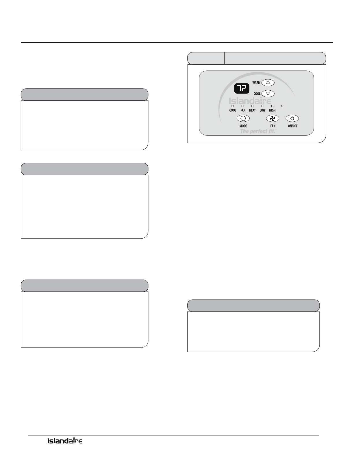
Manufacturer of Quality Air Conditioning and Heating Products • www.islandaire.com • sales@islandaire.com • (800)-886-2759
37
Control panel
Use the control panel to power on/o, select mode, select
fan speed, and adjust the set temperature.
Power Control
e ON/OFF button turns the unit on and o.
Auto Restart Feature
To prevent multiple units from powering
up simultaneously aer a power outage,
there will be a random 5 to 15 second delay
before the unit turns on aer power has been
restored.
Memory Recall Feature
e control board utilizes “non-volatile”
memory; computer memory that can retain
stored information when not powered. is
allows all control settings to be saved and
recalled aer a power failure or if power is
disconnected while servicing the unit.
Compressor Short Cycle Protection
Built-in three minute timing delay: If cycle is
interrupted, the compressor will not restart
for three minutes. On all initial power ups
there is a one-time, 3 minute time delay
before the unit will function.
Digital Control Panel
AUTO
Figure 41 Digital Control Panel
Display
e display shows the room temperature (return air
temperature) when the unit is in operation. When
the temperature is adjusted by pressing the “Warm” or
“Cool” buttons the display briey shows the set tempera-
ture, for three seconds and then defaults back to room
temperature.
Mode Control - Cool,
Fan, and Heat
A light will indicate which mode is currently being uti-
lized.
Cool Mode: The unit will circulate and cool the air.
Fan Mode: The unit will only circulate the air.
Heat Mode: The unit will circulate and heat the air.
Heater Safety Feature
When heater is powered off, fan will
automatically stay on and run for 60 seconds to
ensure the removal of residual heat.
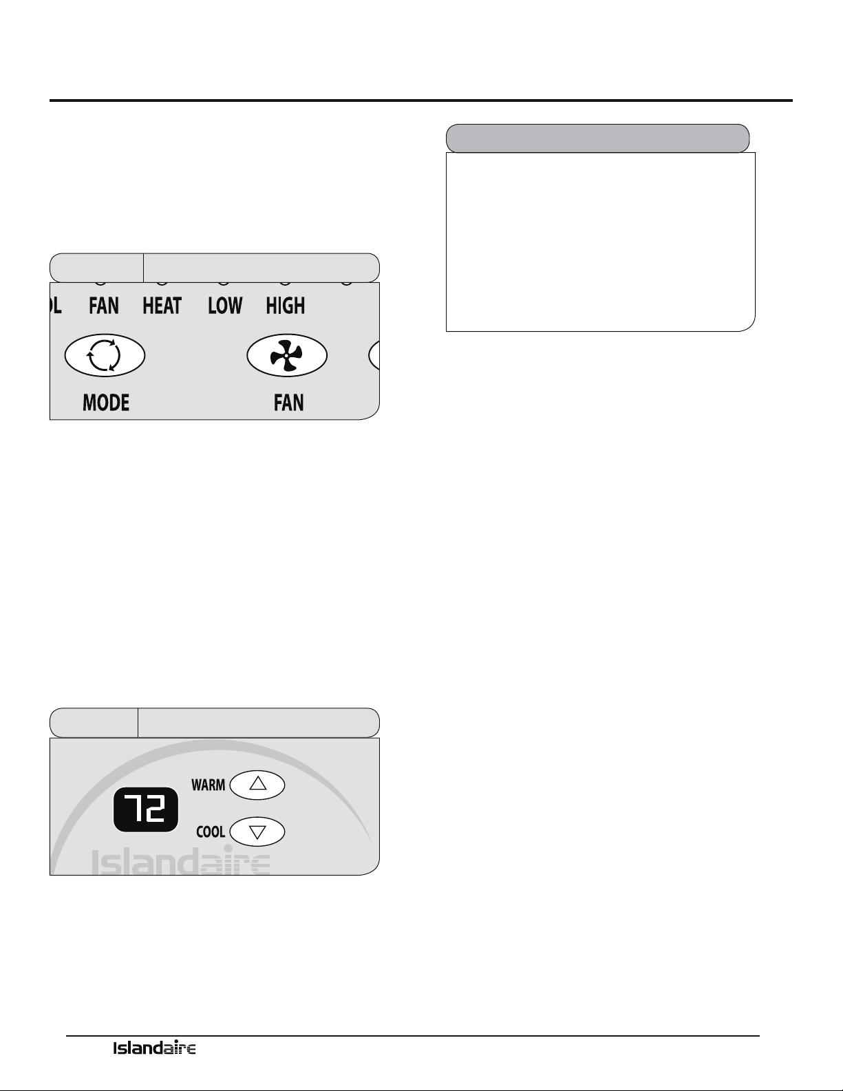
Manufacturer of Quality Air Conditioning and Heating Products • www.islandaire.com • sales@islandaire.com • (800)-886-2759
38
Digital Control Panel (cont.)
Fan Speed Control - Low,
High, and Auto
e fan speed settings are adjusted with the Fan button.
Each time the button is depressed it changes the setting
between Low, High and Auto. A light will indicate which
setting is currently being used.
AUTO
Figure 42 Fan Controls - Digital Control Panel
If either the Low or High fan settings are selected the fan
will continuously operate in the selected Low or High
speed even if the set temperature has been reached.
When the Auto feature is selected, while the air condi-
tioner is in the COOL or HEAT mode, the fan speeds
will change between low and high automatically as the
temperature in the room changes and the fan will cycle
o when the set temperature is reached.
Temperature Controls
e Warm and Cool buttons are used to raise or lower
the set temperature. By depressing both buttons at once,
the display will toggle between Celsius and Fahrenheit.
Figure 43 Temp Controls - Digital Control Panel
If the temperature in a vacant room falls
below 50 °F (4.4 °C) the freeze prevention
thermostat automatically starts the heating
cycle to prevent freezing conditions. All
other operations will be disabled until the
temperature rises above
58 °F. When the temperature of the freeze
prevention thermostat rises above 58 °F, the
system will resume normal operation.
Freeze Protection Feature
Operating Guidelines
•Do not block airow. Ecient operation of the
unit depends on free circulation of air.
•Paper, leaves, and other debris can reduce e-
ciency and cause serious damage to the compres-
sor.
•Ensure that objects such as drapes, furniture, or
plants are not blocking supply and return airow.
•Do NOT operate unit with front panel removed or
without lter, as this will void any warranties.
•Keep doors and windows closed. Leaving them
open will increase the workload on the unit and
will result in higher operating cost and excessive
condensate.
•Do NOT operate unit during construction. Con-
struction dust can clog lter and cause permanent
damage to other components.

Manufacturer of Quality Air Conditioning and Heating Products • www.islandaire.com • sales@islandaire.com • (800)-886-2759
39
Remote Thermostats
Remote Thermostat
Control
e PTAC unit can be controlled by any remote elec-
tronic thermostat that can interface with RCBWYG ter-
minals. A wiring harness is provided with conductors for
all applications (Heat Cool, Heat Pump, Multispeed Fan,
etc.). See details on the next page. e Control Selection
jumper must be in T’STAT position. During a call, the
remote thermostat will pass R back to the controller on
a respective terminal. e push buttons on the touchpad
become inactive in the remote thermostat mode.
Note: In terms of outputs, there are two types of thermo-
stats: Relay Contacts and Solid State.
Manufacturers of solid state output thermostats include
loading resistors in their installation kits. ese 560
Ohm, 3W resistors are designed to load thermostat solid
state outputs in order for the output voltage to be either
0 or 24 Vac (i.e., no oating voltage). ese resistors are
connected from W, Y, G to common (C), respectively.
You can wire any type of 24 Vac thermostat straight into
the Remote ermostat Interface on the PTAC control
board (see page 40).
Wireless Wall
Thermostat
Wireless wall thermostats are designed to provide precise
temperature control without the installation labor and
expense of wiring.
•Powered by AA batteries
•Mounts in any suitable location that will provide
an accurate room temperature reading.
•Large LCD display provides the user with current
room temperature, set point temperature, time,
program interval, and other system status informa-
tion.
REMOTE CONTROL NODE
Used with a wireless wall thermostat, the RCN commu-
nicates with the thermostat using unlicensed 900 MHz,
radio frequency energy.
Energy Saving Options
Automatic Change-Over Remote Mounted ermostats
can be obtained to switch from heating to cooling and
from cooling to heating automatically. With automatic
change over, the operation of the heating cycle or the
cooling cycle is determined by the temperature require-
ment of the space.
Most thermostats with this feature are set to change over
when the room temperature varies 3-½ °F from the set-
point. e unit is placed in cooling mode when the set-
point is over 3-½ °F; 3-½ °F under the set point places
the unit in the heating mode. is
3-½ °F variation is usually adjustable from a ½ °F dead
band to a 5 °F dead band. Each cycle is run until the
set point temperature is reached, then that cycle is de-
energized. On some thermostats, the automatic change
over function can be overridden manually by moving the
thermostat selector switch to “heat” or to “cool.”
Fan operation with an automatic change over thermostat
is controlled by the fan selector switch. When placed in
the “fan” mode, the fan runs continuously. When placed
in the “auto” mode, the fan will only energize when the
thermostat calls for heating or cooling.
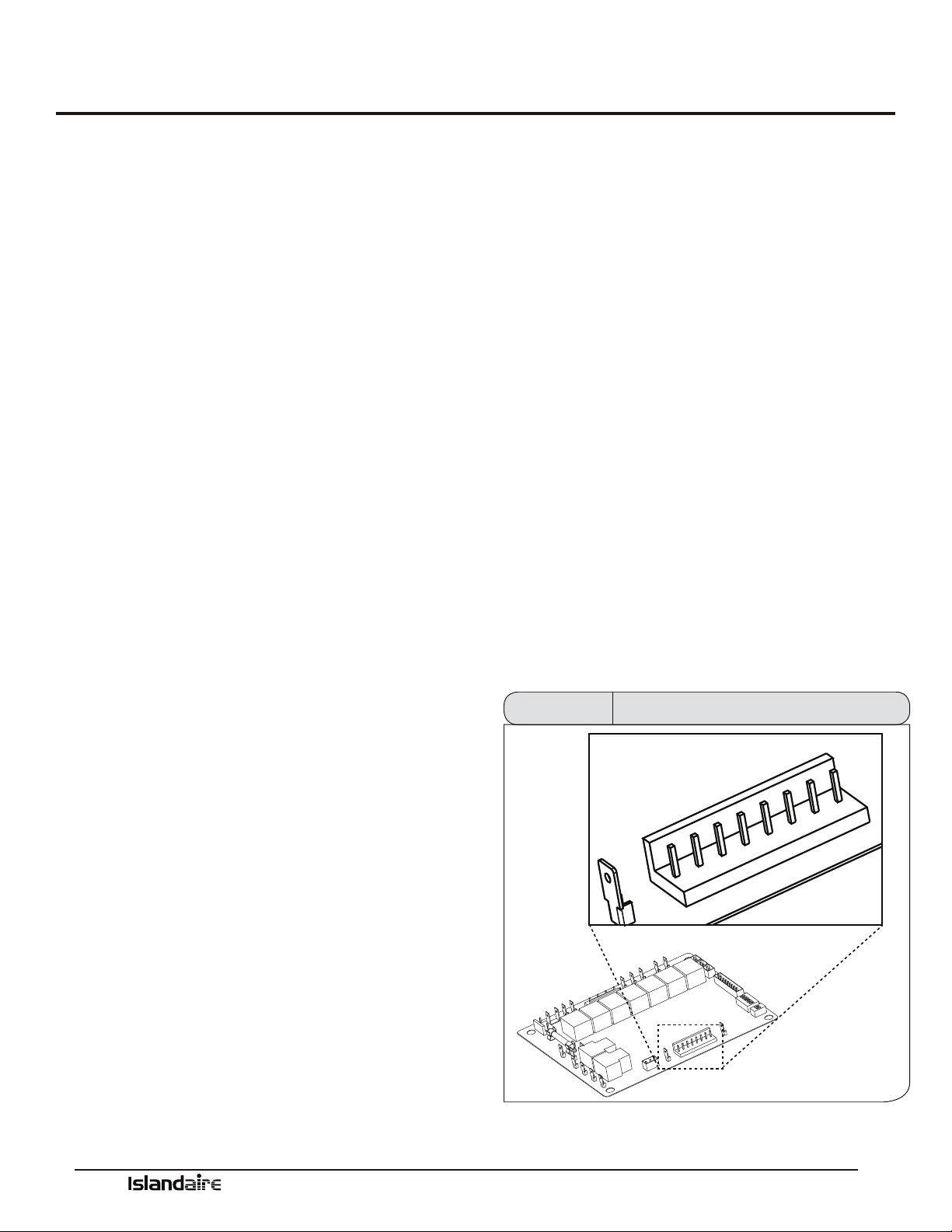
Manufacturer of Quality Air Conditioning and Heating Products • www.islandaire.com • sales@islandaire.com • (800)-886-2759
40
e remote thermostat interface terminal block is located on the power module board. A Wiring harness is provided with
conductors for all applications (Heat Cool, Heat Pump, Multispeed Fan, etc.). It provides a connection for remote thermo-
stat and energy management inputs.
To convert to thermostat operation:
1. Shut main power to unit o.
2. Access main control board and turn remote thermostat dip switch on.
3. Plug in the supplied thermostat harness.
4. Connect wires to eld-supplied thermostat.
Remote Thermostat Interface
Terminal R (Red)
Low voltage terminal to supply voltage to an external
wall mounted thermostat. is terminal is capable of
supplying 100 mA at 18-30 Vac RMS over the entire
input voltage range specied.
Terminal LS (Purple)
When this low voltage terminal is connected to the R
terminal, the compressor and electric heater are disabled
to provide an energy management system interface.
Terminal GH (Green)
When this low voltage terminal is connected to the R
terminal, and the unit is in remote mode, the blower/fan
will be requested for operation on high speed.
Terminal B (Blue)
When this low voltage terminal is connected to the R
terminal, and the unit is in the remote mode, the revers-
ing valve is energized. Hydronic and electric heat shall
be attempted as backups if the B terminal is asserted and
the compressor is locked out or disabled. is is subject
to the congured heat modes available.
Terminal Y (Yellow)
When this low voltage terminal is connected to the R
terminal, and the unit is in remote mode, the compressor
will be switched on (the GL or GH terminal must also be
connected to the R terminal).
Terminal W (White)
When this low-voltage terminal is connected to the R ter-
minal and the unit is in the remote mode, rst hydronic
heat is attempted and electric heat is switched on as
backup (the GL or GH terminal must also be connected
to the R terminal). is is subject to the congured heat
modes available.
Terminal GL (Orange)
When this low voltage terminal is connected to the R
terminal, and the unit is in remote mode, the blower/ fan
will be requested for operation on low speed.
Terminal C (Black)
Low voltage terminal, 24 Vac common, to provide oppo-
site polarity voltage to wall thermostat.
C
R
LS
GH
B
GL
Y
W
Thermostat Terminal Block Figure 44
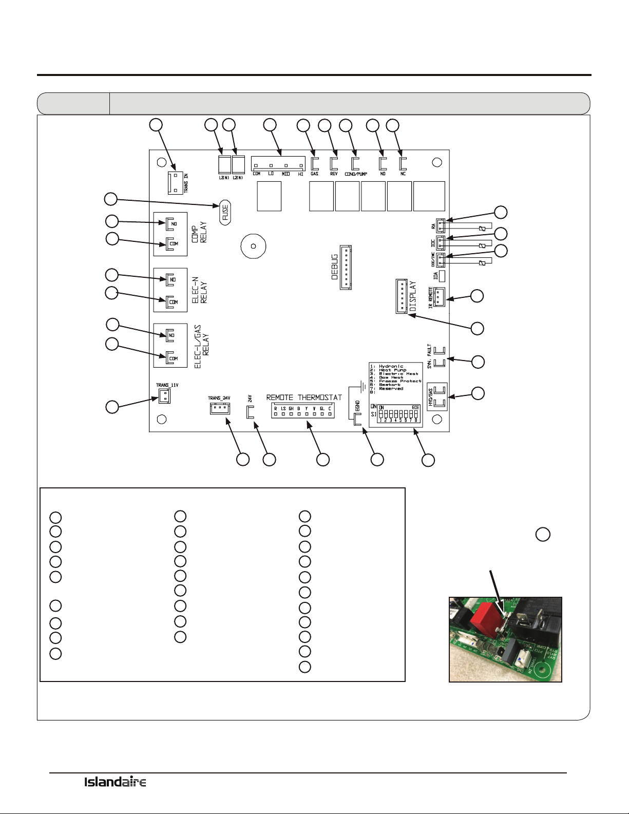
Manufacturer of Quality Air Conditioning and Heating Products • www.islandaire.com • sales@islandaire.com • (800)-886-2759
41
Control Board
Fuse
8.0 Amp 250V fuse
on the control board.
V
An easily replaceable
is conveniently located
EGND – ACCESSORY
HYD/GAS – FAN SWITCH
HI
LO
COM
A
B
KEY
C
D
E
F
TRANS 24V
24 VAC – ACCESSORY
REMOTE THERMOSTAT
DIP SWITCH - HEAT
CONFIGURATION
G
H
I
J
K
L
M
N
O
P
SYN FAULT
IR REMOTE
ODC/IWC- OUTDOOR COIL SENSOR
IDC – INDOOR COIL SENSOR
RA – RETURN AIR SENSOR
N.C. – NORMALLY CLOSED
N.O. – NORMALLY OPEN
COND – CONDENSER MOTOR
REV – REVERSING VALVE
GAS – GAS VALVE
FAN – EVAPORATOR MOTOR
S
T
U
W
X
Y
Z
AA
BB
CC
L2(N)
L2(N)
TRANS IN
TRANS 11V
N.O. – COMPRESSOR
COM – ELEC_L
N.O. – ELEC_N
DISPLAY
COM – COMPRESSOR
COM – ELEC_N
N.O. – ELEC_L
V
FUSE
Q
R
W
X
Y
Z
AA
BB
CC
U T
S R
A
P O N M
C
Q
L
J
I
G
F
K
B
D
E
H
V
Fan Con/Cyc for
heating
Figure 13 Control Board Physical Features
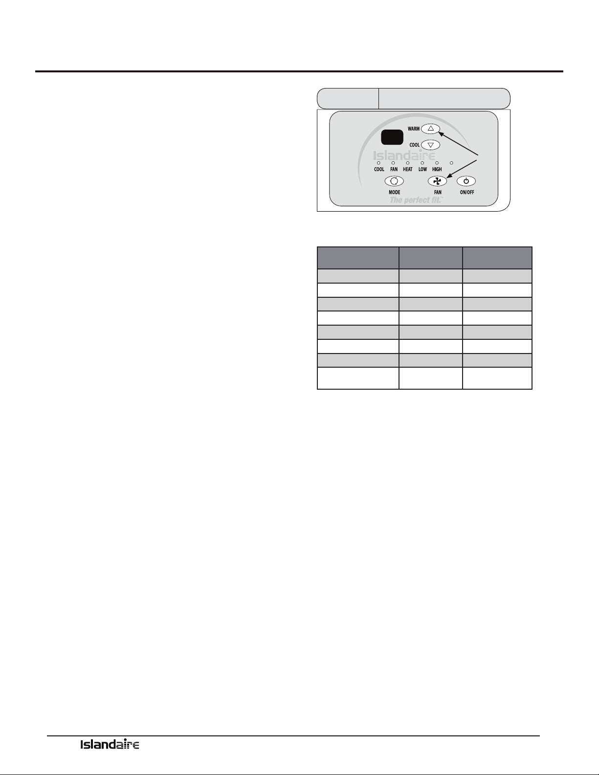
Manufacturer of Quality Air Conditioning and Heating Products • www.islandaire.com • sales@islandaire.com • (800)-886-2759
42
Temperature Limiting
Set Temperature Limiting
HOW TO SET THE HEATING AND COOLING LIMITS
Setting customized temperature set point ranges can save
energy costs by limiting extreme settings.
To enter the Set point setup mode, hold down the FAN +
WARM buttons for 5 seconds.
While the unit is in this mode, you can now scroll
through a series of codes (R1, R2, R3, R4, etc.) to select
the desired temperature limiting setting. To move from
one code to the next, press the Fan + Warm buttons
together to move to the next code on the digital display.
See chart at right for the codes and the set point range
they each represent.
To accept the new set point, release the buttons for 10
seconds when the desired code is displayed. e change
will take eect when the ON/OFF key is pressed a second
time, returning the display to normal function.
To cancel the change, wait 10 seconds without pressing
the ON/OFF button a second time.
AUTO
R1
Fan
&
Warm
Figure 46
Display - Temp Limit Code
Available Set Point Ranges
DISPLAY CODE LOW LIMIT
(DEGREES F)
HIGH LIMIT
(DEGREES F)
R1 63 86
R2 65 86
R3 65 90
R4 67 88
R5 67 92
R6 69 90
R7 68 72
R8
(FACTORY DEFAULT)
60 90
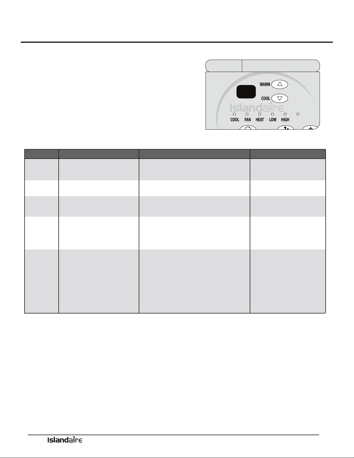
Manufacturer of Quality Air Conditioning and Heating Products • www.islandaire.com • sales@islandaire.com • (800)-886-2759
43
Error Codes
Diagnostic & Error Codes
CONTROL PANEL DISPLAY DIAGNOSTICS
Sensors in the unit continually monitor the indoor coil,
outdoor coil, and outdoor air conditions. If abnormal conditions
are detected, an error code is displayed, removing the guess work
in troubleshooting a unit.
AUTO
E2
Display - Error CodeFigure 47
ERROR CODE DIAGNOSIS CAUSE NOTE
E2
RETURN AIR (RA)
TEMPERATURE SENSOR FAILURE
RA SENSOR BROKEN OR LOOSE AT BOARD CONNECTION
UNIT OPERATION DISABLED
E3
INDOOR COIL (IDC)
TEMPERATURE SENSOR FAILURE
IDC SENSOR LOOSE OR BROKEN AT BOARD CONNECTION
UNIT OPERATION DISABLED
E5
OUTDOOR COIL (ODC)
TEMPERATURE SENSOR FAILURE
UNIT OPERATION DISABLED
E8
ODC SENSOR BROKEN OR LOOSE AT BOARD CONNECTION
UNIT OPERATION DISABLED
E9
OVERHEAT / FREEZE PROTECTION
• REFRIGERANT RESTRICTION
• DIRTY FILTER / EVAPORATOR COIL
• FAILED EVAPORATOR MOTOR
• RETURN SUPPLY AIR RESTRICTED
UNIT OPERATION DISABLEDSYN. FAULT TERMINALS OPEN
HIGH PRESSURE SWITCH OPEN:
• DIRTY CONDENSER COIL (COOLING)
• FAILED CONDENSER MOTOR (COOLING)
• ENSURE BAFFLES ARE INSTALLED (IF REQUIRED)
• REFRIGERANT RESTRICTION
• DIRTY FILTER / EVAPORATOR COIL (HEAT PUMP)
• EVAPORATOR MOTOR FAILURE (HEAT PUMP)
• ALL ADDITIONAL SAFETIES TIED TO SYN. FAULT TERMINALS
SHOULD BE CHECKED

Manufacturer of Quality Air Conditioning and Heating Products • www.islandaire.com • sales@islandaire.com • (800)-886-2759
44
Performance Specifications
Packaged Terminal
Cooling Unit with Heat
Pump or Electric Heating
PART I: SPECIFICATIONS
Size Range: Cooling: 6,800 to 15,000 Btuh
Heating: 6,100 to 14,000 Btuh Heat Pump
4,400 to 17,100 Btuh Electric
PART II: GENERAL
1.01 SYSTEM DESCRIPTION
Single piece, thru-the-wall electrically controlled
unit using hermetic rotary compressor for cooling
and heat pump or electric resistance heat.
A. Insulated Wall Sleeve:
Shall be entirely constructed of galvanized, heavy-
gauge steel with an Antique Ivory powder paint
corrosion resistant nish. Wall sleeves shall be
installed through the wall as shown on plans and
shall have factory provisions for use of appropriate
fastening devices to secure sleeve to the wall. In no
event shall fasteners be installed through the base
pan in the bottom of the wall sleeve.
Wall sleeve shall provide excellent thermal insula-
tion, will have superior outdoor noise absorption
and shall be corrosion free for the life of the prod-
uct.
Wall sleeve must have dimensions of 42 in. width x
16 in. height x 14-7/8 in. depth and be shipped with
a rear weather barrier installed.
B. Outdoor Louvered Grille:
Shall be (stamped) (architectural) anodized alu-
minum as shown on plans. Louver shall be (n-
ished natural) (painted) as shown on the schedule.
Louvers shall be easily installed from the inside of
the building aer the cabinet/wall sleeve has been
installed. Special eld fabricated louvers must be
approved by the PTAC manufacturer as to free area
and air circulation requirements.
Outdoor grille shall resist corrosion, breakage and
match the color specied on drawing schedule and
specications.
C. Subbase:
Subbase will support the wall sleeve when it extends
into the room more than 4 inches. Subbase must
come from the factory pre-assembled, with a built
in receptacle (size as specied on drawing schedule
and specications) or with factory installed hard-
wire, pre-sized for an exact t to the unit.
1.02 QUALITY ASSURANCE
System shall be approved and certied by ETL.
Chassis capacity and eciency performance shall
be tested in accordance with ARI standard 310/380.
Chassis shall meet ASHRAE Standard 90.1 for
minimum energy eciency.
1.03 DELIVERY, STORAGE, AND HANDLING
A. e packaging of the chassis shall be sucient to
protect the chassis from damage during shipment via an
enclosed truck.
B. Chassis, wall sleeves, and grilles shall be shipped in
separate cartons. Universal handling instructions shall
be dened and visible on the carton, from front, back
and sides.
C. Unit shall be stored and handled per manufacturer’s
recommendations.

Manufacturer of Quality Air Conditioning and Heating Products • www.islandaire.com • sales@islandaire.com • (800)-886-2759
45
Performance Specifications (cont.)
2.01 EQUIPMENT
A. General:
Factory-assembled, single-piece heating and/or
cooling unit. Contained within the unit enclosure
shall be compressor, coils, fans and fan motor, heat-
ing means, controls, all wiring and piping, and a full
refrigerant charge (R410A).
B. Chassis:
e chassis shall be a factory-assembled, single
piece heating and/or cooling unit, that is simple to
install and operate. Just slide the chassis into a wall
sleeve, plug it into an outlet, and operate aer instal-
lation. e chassis dimensions shall not exceed 42
in. wide and 16 in. high with room cabinet in place.
e chassis shall consist of the following functional
sections and components:
1. Operating Characteristics:
Chassis shall be capable of starting and running at
115 °F ambient outdoor temperature per maximum
load criteria of ARI Standard 310/380.
2. Electrical:
Chassis shall be equipped with a 58 in. power cord.
e chassis current draw shall be specied on the
chassis nameplate and match electrical require-
ments specied on the Contract drawing schedule
and specications.
e power cord plug conguration shall conform to
NEMA standards and the rating shall support the
current draw of the electric resistance heater.
For 265V installations, UL codes require the use of
an electrical equipped subbase for power cord usage
or hardwire conduit for non-corded installations.
C. Airow System:
e airow system shall consist of one permanent
split-capacitor, direct-drive permanently lubricated,
two-speed fan motor for the indoor and outdoor
fans. e outdoor fan shall be a dynamically bal-
anced, corrosion resistant polymer multi-blade
axial ow design, with integrated slinger ring. e
indoor fan shall be a dynamically balanced, poly-
mer, reverse curve blower wheel, to assure uniform
air distribution. e Fan Motor shall be of an
enclosed design to reduce the eects of moisture
and corrosion.
D. Compressor and Refrigerant:
e rotary-type Compressor shall be fully hermetic
with internal and external vibration isolation. e
refrigeration system will be sealed and contain a full
refrigerant charge (R410A).
E. Coils:
Condenser and evaporator coils to be constructed of
high-eciency, lanced sine wave enhanced alumi-
num ns and seamless axial grooved copper tubing,
necessary to achieve EER and COP rating, as speci-
ed on the chassis name plate.
F. Factory-Installed Electric Heater:
e factory-installed, open coil type, electric heater
is standard in heat/cool and heat pump chassis. e
electric heater shall contain both an automatic reset
and a one-shot over temperature protection device.
e heating capacity of the electric heater shall be as
identied on the Contract drawing schedule and in
the specications.

Manufacturer of Quality Air Conditioning and Heating Products • www.islandaire.com • sales@islandaire.com • (800)-886-2759
46
Performance Specifications (cont.)
G. Front Panel (supplied with chassis):
Front panel shall be constructed of a polymer mate-
rial to resist breakage and corrosion. It shall have
a front louvered surface with integrated air lters.
e air lters shall be easily accessible without
removing the front panel from the chassis.
H. Fresh Air Vent
e chassis shall have a manual adjustable fresh air
vent with a concealed manual control. e vent
control shall allow a maximum of up to 72-75 CFM
of fresh air to be drawn into the room when the
indoor fan is operating and the door is open.
I. Condensate Removal System
e chassis shall have a condensate removal system
consisting of a condensate suction port, to draw and
atomize condensate, and a slinger ring integrated
in the outdoor fan, to disperse condensate onto the
condenser coil to be evaporated.
Condensation accumulated during reverse cycle
heating must NOT be evaporated against the indoor
coil so as to prevent contamination of the indoor air
with pollutants and odors. Condensation must be
disposed of using a (external/internal) drain system
as shown on plans.
3.01 CONTROLS
All standard models shall be equipped with electrome-
chanical controls to simplify the serviceability of the unit.
A. Standard Controls
e chassis shall have standard controls, accessible.
e mode selection control shall provide OFF, FAN
ONLY, HEAT or COOL operations.
e temperature selection control shall be an
adjustable thermostat with upper and lower lim-
its.
B. Continuous Fan
All standard models shall have a continuous/ fan cycle
selector switch located behind the front panel. It shall
allow the selection of continuous fan operation for
maximum comfort or cycle operation (fan only runs
with cooling or heating operation) for maximum
energy savings.
C. Temperature Limiting
All standard models shall have Temperature Limiting
management built in to the system controls.
e temperature limiting controls allow a room
temperature set-point range to be established, to avoid
extreme temperature settings, to maximize energy
savings.
D. Emergency Heat
Emergency Heat Switch (Heat Pump Models Only),
upon failure of the compressor, shall automatically
disable the compressor in heating mode and only
allow the use of electric strip heater during heating
cycles. e Emergency Heat switch is active at all
outdoor ambient temperatures.
E. Thermostat
Wall thermostat chassis shall come from the factory
ready for wall thermostat installation, including a
blank out plate in place of the digital control panel.
Installation of harness and DIP switch required.
F. Fan Speed Control
Wall thermostat chassis (RC and RP models) shall
have a user-selectable fan speed control switch, on the
control panel, to optimize fan speed for maximum
comfort.

Manufacturer of Quality Air Conditioning and Heating Products • www.islandaire.com • sales@islandaire.com • (800)-886-2759
47
Performance Specifications (cont.)
G. Protection Circuits:
Compressor shall have automatic reset, over tempera-
ture and over current protection. e fan motor shall
have an inherent, automatic reset over temperature
protection. e electric heater shall have two over
temperature protectors.
4.0.1 HEAT PUMP OPERATION
Heat pump units shall have the selected room tempera-
ture maintained by cycling either in the heat pump mode
or electric strip heat. A heat pump unit with electric heat
is switched from the heat pump mode to electric strip
heat when the outdoor coil temperature is 20 °F or when
the heat pump cannot keep up with the heating load and
a two-stage thermostat is used.
For heat pump operation, a room thermostat with a B**
(heating changeover) terminal is required. is will
mean that some “auto changeover” thermostats cannot
be used, as many of them either do not have a B** termi-
nal, or else energize the B** terminal continuously when
in the “auto” position.
4.0.2 ELECTRIC HEAT OVERRIDE
For heat pump applications, electric heat comes on only
when the outdoor coil temperature is below
28 °F, maximizing the amount of time the unit operates
in the more ecient heat pump mode. e minimum
COP for heat pumps, at 47 °F DB outdoor, must be 2.9
for all sizes.
(Heat pump models shall also include reversing valve).
4.0.3 REVERSE CYCLE
A Heat Pump WITH back-up electric heat –
e reversing valve, the compressor, the outdoor con-
denser fan motor and the indoor fan motor shall be
energized. Reverse cycle heating shall occur when the
outdoor coil temperature is
28 °F and above. If outdoor coil temperature drops
below 28 °F or the Outdoor air temperature drops to
35 °F or less, electric heat is the only source of heat.
When the outdoor coil temperature rises back to 40 °F
or above, the Compressor or electric heater is used.
A temperature-sensing device shall be used to moni-
tor the outdoor coil temperature to limit frost buildup.
Defrosting of the outdoor coil will be activated when
outdoor coil temperature drops below 28 °F or out-
door air temperature drops to 35 °F or less. Defrost-
ing is terminated when outdoor coil temperature rises
back to
40 °F. During defrosting, both compressor and the
outdoor fan are turned o. e indoor fan will run at
its set speed.
Condensation accumulated during reverse cycle heat-
ing must NOT be evaporated against the indoor coil
so as to prevent contamination of the indoor air with
pollutants and odors. Condensation must be disposed
of using a (external/internal) drain system as shown
on plans.

Manufacturer of Quality Air Conditioning and Heating Products • www.islandaire.com • sales@islandaire.com • (800)-886-2759
48
B. Heat Pump WITHOUT back-up electric heat
e reversing valve, the compressor, the outdoor con-
denser fan motor and the indoor fan motor shall be
energized. Reverse cycle heating shall occur when the
outdoor temperatures are 35 °F and above.
If outdoor coil temperature drops below 28 °F or
the outdoor air temperature drops to 35 °F or less,
the compressor stops and there is no source of heat.
When the outdoor coil temperature rises back to
40 °F or above, the compressor reverse cycle is the
heat source.
A temperature-sensing device shall be used to moni-
tor the outdoor coil temperature to limit frost buildup.
Defrosting of the outdoor coil will be activated when
outdoor coil temperature drops below 28 °F of out-
door air temperature drops to 35 °F or less. Defrost-
ing is terminated when outdoor coil temperature rises
back to 40 °F. During defrosting, both compressor
and the outdoor fan are turned o.
e indoor fan will stop if indoor coil temperature
falls below 78 °F. It will restart at its set speed when
indoor coil temperature rises back to 80 °F.
4.01 ACCESSORIES:
A. Metal Wall Sleeve shall be a one-piece, extended wall
sleeve, with factory installed insulation.
B. Architectural louver shall be painted aluminum for a
superior color match to the building.
C. Subbase shall be pre-assembled from the factory and
be UL listed.
Subbase options include:
1. Non-electrical subbase: e non-electrical subbase
shall be pre-assembled and provides mechanical sup-
port and requires no wiring.
Performance Specifications (cont.)
2. Electrical subbase: e electrical subbase shall be
pre-assembled with factory-installed electrical junc-
tion box containing a receptacle for corded units.
3. Hardwired subbase: e hardwired electrical sub-
base shall be pre-assembled with factory installed
electrical junction box containing 19 inches of
exible conduit (for a perfect t to the unit) and all
mating connections.
D. Hardwire kit shall provide a permanent
connection
to the unit.
e hardwire kit mounts on the front right side of the
unit and shall have 36 inches of exible steel conduit
and a connector for easy connect/disconnect.
E. Condensate Drain
is universal drain kit shall be used internally or
externally to route excess condensate to a drainage
system. It can be eld-installed on any Islandaire wall
sleeve. e drain kit shall be attached to the exterior
right or le side of the wall sleeve for external drain-
ing or may be mounted to the bottom of the wall
sleeve for internal draining.
F. Lateral Duct:
e kit shall include an adapter plenum, extension
duct, wall register and wall molding. e lateral duct
system allows one system to heat or cool two adjacent
rooms, by directing up to 30% of the airow to the
adjacent room.
G. Power Vent:
is specially designed fan delivers up to approxi-
mately 95 CFM of fresh air through the vent while the
fan is operating.

Manufacturer of Quality Air Conditioning and Heating Products • www.islandaire.com • sales@islandaire.com • (800)-886-2759
49
Performance Specifications (cont.)
H. Front Desk Control:
Unit controls shall provide front desk control on all
units, allowing individual units to be turned on and
o from a remote location or by a motion-sensing
device. Front desk controls shall interface to most
energy management systems.
I. Security Door:
e key-locking security door kit shall prevent
unauthorized access to the unit’s heating and cooling
controls and prevents tampering with units in public
locations and institutions. e security door shall
include two matching keys and keys shall be common
to all Islandaire Security Door kits.

Manufacturer of Quality Air Conditioning and Heating Products • www.islandaire.com • sales@islandaire.com • (800)-886-2759
50
Notes
____________________________________________________________________________________
____________________________________________________________________________________
____________________________________________________________________________________
____________________________________________________________________________________
____________________________________________________________________________________
____________________________________________________________________________________
____________________________________________________________________________________
____________________________________________________________________________________
____________________________________________________________________________________
____________________________________________________________________________________
____________________________________________________________________________________
____________________________________________________________________________________
____________________________________________________________________________________
____________________________________________________________________________________
____________________________________________________________________________________
____________________________________________________________________________________
____________________________________________________________________________________
____________________________________________________________________________________
____________________________________________________________________________________
____________________________________________________________________________________
____________________________________________________________________________________

Manufacturer of Quality Air Conditioning and Heating Products • www.islandaire.com • sales@islandaire.com • (800)-886-2759
51
Notes
____________________________________________________________________________________
____________________________________________________________________________________
____________________________________________________________________________________
____________________________________________________________________________________
____________________________________________________________________________________
____________________________________________________________________________________
____________________________________________________________________________________
____________________________________________________________________________________
____________________________________________________________________________________
____________________________________________________________________________________
____________________________________________________________________________________
____________________________________________________________________________________
____________________________________________________________________________________
____________________________________________________________________________________
____________________________________________________________________________________
____________________________________________________________________________________
____________________________________________________________________________________
____________________________________________________________________________________
____________________________________________________________________________________
____________________________________________________________________________________
____________________________________________________________________________________

Warranty
LIMITED ONE YEAR PARTS AND LABOR PLUS ADDITIONAL 2ND THROUGH 5TH YEAR
SEALED SYSTEM PART ONLY WARRANTY COVERING ISLANDAIRE THRU-WALL AIR
CONDITIONERS & HEAT PUMPS
THIS WARRANTY APPLIES TO THE AIR CONDITIONER UNIT (“THE UNIT”) THAT IS THE SUBJECT OF THIS
SALE AND IS IN LIEU OF ALL OTHER WARRANTIES EXPRESSED OR IMPLIED. THIS WARRANTY DOES NOT AP-
PLY TO ANY ACCESSORY THAT IS NOT A PART OF THE UNIT AS SHIPPED BY ISLANDAIRE. THIS WARRANTY
APPLIES ONLY TO THE ORIGINAL EQUIPMENT AT THE ORIGINAL INSTALLATION LOCATION. PROOF OF
PROPER, ROUTINE MAINTENANCE WILL BE REQUIRED IN ORDER TO MAINTAIN EXTENDED WARRANTY.
ISLANDAIRE the “Company” of St. James, New York warrants that the unit is free from defects in material and workman-
ship under normal use and service, for the twelve-month period following the date of installation*.
WARRANTY Coverage includes repair or replacement, at the Company’s option, of any defective parts that fail under
normal use for the rst 365 days aer the date of equipment installation* under the terms, conditions and limitations of
the warranty. All defective parts shall be returned within thirty days aer removal to the Company at such locations as the
Company may designate. Islandaire reserves the right to impose an inspection charge and/or a restocking fee in cases where
parts or equipment have been improperly returned as defective and/ or as being in warranty. A warranty part can only be
replaced one time over the duration of the warranty period.
WARRANTY coverage also includes Labor Charges on all covered repairs performed by a Islandaire Authorized Service
Agent in accordance with the terms, conditions and limitations of the warranty. Extra charges such as emergency calls,
nuisance calls, mileage, overtime or shipping are not covered.
On occasion, wires may become disconnected or components may be dislodged from their bases as a result of rough
handling during transport, causing improper functioning of the unit. Immediately following installation, the installing con-
tractor is responsible to check, test and start the unit, including physically operating the unit in both cooling and heating
modes, and correcting any minor deciencies noted. Additionally, the installing contractor is responsible to provide unit
operation instruction by an experienced person.
ADDITIONAL SEALED SYSTEM WARRANTY Coverage includes replacement of any part of the sealed refrigeration
system, including the compressor, evaporator, condenser and connecting tubing, that proves to be defective from the 2nd
through 5th year from date of installation. Labor is not included. Freight charges for replacement and return of defective
warranty parts will be the Company’s responsibility.
IN NO EVENT SHALL THE COMPANY’S MAXIMUM LIABILITY EXCEED THE SELLING PRICE OF THE UNIT
CLAIMED TO BE DEFECTIVE.
As a condition precedent to the Company’s obligation under this WARRANTY, it shall be the obligation of the Owner dur-
ing the designated WARRANTY period to furnish the following information to the Company within three days aer unit
failure: 1) Model Number and Serial Number of unit involved, 2) A full and complete description of the problem encoun-
tered with the unit. Upon receipt of the above information, the Company will reply to the Owner within a period not to
exceed een working days, with a description of the action the Company desires to take.
For warranty service, contact an Islandaire Authorized HVAC Service Agent.
Contact the Islandaire Customer Service Department at U.S. 800-886-2759.
To validate this WARRANTY, you must complete the registration information below and return the pre-addressed card
to Islandaire within seven days of equipment installation. e actual warranty type for your equipment is stated on the
original Islandaire invoice for said equipment. Proof of installation date is required. *Please be advised where no Warranty
Registration Card has been returned, the original date of invoice of the equipment shall become the start date of the
warranty period.

EZ REPLACEMENT GUIDE
TO THRU-WALL AIR CONDITIONERS AND HEAT PUMPS
Original Model
Case
Height
Case
Width
Our
Model Original Model
Case
Height
Case
Width
Our
Model
Amana® Keeprite®
PT 42 x 16 Series 16 42 42 Climette 18 5/16 32 CS
PB 26 x 16 Series 16 26 26 Seasonall 18 5/16 32 CS
American Air Filter® Lennox®
Enersaver Type 16 16 37 1/2 16 PTEIA Series 22 1/4 38 PT
Type 16 Hydronic 16 41 1/2 16
McQuay®
Nelsonaire Series 25 16 36 1/2 25 C/EC 27 3/8 54 1/2 EC
American Standard®
EB Series 22 30 5/8 EB
TW Series Type 41 16 36 1/2 41 J/EJ Series 14 30 JA
Type 40 Remotaire(SR) 16 1/2 37 40 K, EK and RK Series 13 15/16 36 KF
Applied Comfort®
Type EA, ES and RS 16 3/8 44 7/8 ED
DM/DMQ 18 5/16 32 CS Type NE 16 42 NE
SC Series 16 40 SC
Mueller®
SC Series 16 36 RM Climatrol 16 48 UN
Carrier® Remington®
51PH Wallmate 18 15/16 32 CS J/EJ Series 14 30 JA
Cartaret®
K, EK and RK Series 13 15/16 36 KF
Type 45 16 1/2 37 45 Type 41 16 36 1/2 41
Chromalox®
Type 45 16 1/2 37 45
Space Command 16 1/2 45 1/8 CH
Simonaire®
CAM (2 section) 15 35 1/2 CX SSK 16 42 RT
Chrysler®
15 1/2 36 CY SSEZ 16 42 RT
Climate Master®
SSCT 16 42 RT
Climate Master Series 700AD 16 36 AD
Singer®
Climate Master Series 701 16 40 1/2 C7 C/EC 27 3/8 54 1/2 EC
Climate Master
Series 702, 703 & 704
16 36 CM EB 22 30 5/8 EB
Dunham Bush®
J/EJ Series 14 30 JA
New Port III 25 52 N3 K, EK and RK Series 13 15/16 36 KF
New Port IV 25 52 N4 Type 41 16 36 1/2 41
Embassy®
Type 45 16 1/2 37 45
Weathertwin 16 36 RM Type EA, ES and RS 16 3/8 44 7/8 ED
Fedders® Slant Fin®
Maxizone Series 16 1/4 27 MX JK 16 42 JK
Unizone 16 48 UN CC Monterrey 16 42 CC
Friedrich®
Monterrey 17 1/2 36 FM
Climate Master Series 700AD 16 36 AD
Suburban Dynaline®
Climate Master Series 701 16 40 1/2 C7 Gas Unit 16 42 GS
Climate Master Series
702, 703 & 704
16 36 CM
TPI®
ET Series 20 28 ET Ra-Matic 16 36 RM
TE Series 16 42 TE
Weil-Mclain
Vert-I-Pak 32 23 VP ClimateMaster Series 700AD 16 36 AD
General Electric®
Climate Master Series 702,
703 & 704
16 36 CM
Zoneline 16 42 42
Westinghouse®
AJ Series 16 26 26 RB Series 15 38 1/2 RB
AZ Vertical 31 23 1/4 VP
Worthington®
16 48 UN
Heil Quaker® Zoneaire®
SEA Series 14 1/2 35 7/8 HQ CHP Series 18 5/16 32 CS
SHA Series 14 1/2 35 7/8 HQ CSM Series 18 5/16 32 CS
Series C 18 5/16 32 CS Zoneaire‚ RM Series 16 36 RM
Ice-Cap / Ice Air®
Zoneaire‚ SC Series 16 40 SC
RSK Series 16 36 RK
Custom Products
RSCT Series 16 42 RT
RSWL Series 13 1/4 56 1/2 WL
ITT Nesbitt®
Vertical Units, Fan Coils, and other related HVAC products.
(Consult with Factory)
Challenger Series 16 1/4 42 1/4 NC
Roomate Series - N - - CY
If you don’t see the unit you’re looking for in the above list,
please call us about having a unit custom designed for you.
Modular Roomate (MW) - - NR

THE C U RE FOR UN COND I T IONED MAK E-U P AIR
T M
Ask your salesman about our
DR. PTAC option!*
*100% conditioned
fresh air
NEW!
Vertical Unit Available
For New Construction and as
Replacement for:
GE AZ Vertical, Friedrich Vert-I-Pak
and First Company SPX
Locally Represented By:
500 Middle Country Road, St. James, NY 11780 • 1-800-886-2759
e-mail: sales@islandaire.com • www.islandaire.com
Ph: 631-471-2900 • Fax: 631-471-2913