
© DreamLine
®
All Rights Reserved
© DreamLine
®
All Rights Reserved
PLEASE REVIEW THIS ENTIRE MANUAL PRIOR TO INSTALLATION
1-866-731-2244
ENIGMA-XO
SHOWER AND TUB DOOR INSTALLATION INSTRUCTIONS
Do Not Return Product to the Store. Contact DreamLine® with any questions
IMPORTANT!
DreamLine
®
reserves the right to alter, modify or redesign products at any time without prior notice for the
purpose of product improvement and customer experience. Please refer to the model’s web page on
DreamLine.com for the latest technical drawings, installation manuals, warranty information or additional
product details.
##=finish
06- Oil Rubbed Bronze
07- Brushed Stainless Steel
08- Polished Stainless Steel
18- Tuxedo
09- Satin Black
SHDR-61727620-##
SHDR-61606220-## SHDR-61487620-##
SHDR-51547620-##
SHDR-61607620-##
ENIGMA-XO Shower and Tub Door Manual Ver 1 Rev 3 062019
©2019 DreamLine
®
All Rights Reserved

© DreamLine
®
All Rights Reserved
© DreamLine
®
All Rights Reserved
This model is treated with DreamLine’s
exclusive ClearMax
TM
Glass technology.
This is a specially formulated coating
that prevents the build up of soap and
water spots.
Install the surface with the ClearMax
TM
label towards the inside of the shower.
Please note that depending on the
model, the glass may be coated on
either one or both surfaces.
For best results, squeegee the glass after
each use and dry with a soft cloth.
Installation Date
OD Number
(optional)
SKU Number
*found on the shipping box or label
if available.
Purchase Order
Number
Store/Vendor
Purchased From
Installed By:
Record the following purchase information for your records or in the event you need to contact DreamLine
®
:
ENIGMA-XO Shower and Tub Door Manual Ver 1 Rev 3 062019
©2019 DreamLine
®
All Rights Reserved
© DreamLine
®
All Rights Reserved
© DreamLine
®
All Rights Reserved
Table of Contents
Section Title Page #
ClearMax® Coating Information —
Warnings and General Preparation 2
Manual Selection 3
Important Model Information 4
Recommended Reinforcement Information 5
Model Specific Preparation 6
Tools 7
Detailed Diagram 'A' of Shower Door Components & Parts List A 8-10
Detailed Diagram 'B' of Shower Door Components & Parts List B 11-12
Installation Steps 13-38
Guide Block Installation 24-25
Guide Rail Bracket Adjustment 26
Upper Roller Assembly Installation 31
Lower Roller Assembly Installation 32
Roller Wheel Assembly Adjustment Procedure 33
Vinyl Seals & Handle Installation 34
Door Stopper Installation 35
SafeStop™ Bumper Installation 36,37
Product Maintenance 39
Troubleshooting 40
Factory Part Information 41-45
ENIGMA-XO Shower and Tub Door Manual Ver 1 Rev 3 062019
©2019 DreamLine
®
All Rights Reserved
Symbol Legend
72”
MODEL
ONLY
!
TIP
NOTE
TIP - for ease of installation.
NOTE - take note of special
feature; additional information.
INCORRECT -
not recommended.
CORRECT -
recommended.
REQUIRED -
requires special
attention; signifies
a warning.
72” MODEL ONLY -
denotes
parts and special instruction for
the 72” model only. (Not included
with the 48“ or 60” model.)
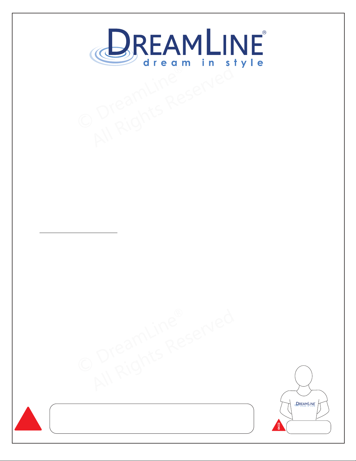
Average Installation Time
4 hrs
© DreamLine
®
All Rights Reserved
© DreamLine
®
All Rights Reserved
I
MPORTANT
• DreamLine® reserves the right to alter, modify or redesign products any time without
prior notice for product improvement and customer experience. Please refer to the
model’s web page on DreamLine.com for the latest technical drawings, installation
manuals, warranty information or additional product details.
• This product should be installed by someone familiar with the construction re
quirements
for this type of project and the care necessary for the safe installation and operation of
the product.
• The safety of any installation is the responsibility of the installer.
• Professional installation recommended.
(All Models)
• Professional installation required.
(Enigma Series)
• To prevent damage or serious injury, Do Not lean against the installed panel/door/glass.
• To prevent damage or serious injury: Do Not attempt to lift or move a heavy lite of glass
alone. Use an assistant and/or a professional grade glass suction cup.
• The installation of some models may require drilling down into the threshold. Contact the
manufacturer of the base, tub, or threshold materi
al with any questions regarding the
drilling of holes into their product.
• All drawings in this installation manual are for illustrative purposes only and are not drawn
to scale.
T
EMPERED GLASS WARNING
• Your Shower Door Glass Could Shatter Without Warning if Improperly Installed or
Mishandled
• Do Not install or operate a shower door if the glass has chipped corners, slivered edges or
is otherwise damaged and/or has been dropped or banged into a hard surface such as
tile, marble or glass.
• The main causes of tempered glass breakage are:
o Improper handling, storage or installation
o Misuse/abuse
o Lack of maintenance
o Failure to replace damaged glass
o Improper handling during storage, unpacking and installation:
o Corners and edges are the most susceptible area to damage on a lite of tempered
glass and should be protected and handled with care during storage, unpacking,
installation and operation. A concentrated point of pressu
re or impact with a surface
harder than itself may cause the tempered glass to shatter. The tempered glass may
release immediately, within several hours or even days later.
o Incorrect installation of door hardware, rollers, hinges, channels, stopper or glass:
o Improper installation may include: loose hardware and/or lack of proper gaskets
between the hardware and glass. Additionally, improper al
ignment of guide rails, wall
profiles or other hardware during installation or operation may place stress on the
glass edges and cause it to break.
o This product must be installed by a professional and experienced installer familiar with
the safe handling of tempered glass.
o Improper use of this product:
o Aggressively opening or closing the door may cause trauma to the glass, which can
lead to breakage. This may occur immediately or hours or even days later.
o The shower door hardware and glass should be inspected periodically:
Instruct the homeowner how to perform a periodic inspection of the shower
hardware and glass - some minor adjustments may be necessary based upon
the use (or misuse) of the shower door. Ensure that the hardware remains tight
and that the door alignment and o
peration are correct. Any adjustments
should be made upon discovery to prevent damage to the product.
Additional considerations should be given to the installation of frameless
tempered glass products in households with young children or an elderly
person due to an increased chance of improper handling. In such cases,
alternatives such as shower curtains or grab bars should be considered.
GENERAL PREPARATION
• After opening all boxes and packages, read this introduction carefully. Check that all the
items are included in the package by marking off the components on the “Detailed
Diagram of Product Components” page. Examine all boxes and packages for shipping
damage. If the unit has been damaged, has a finishing defect, or is missing parts; please
contact our Customer Support depart
ment within
3 business days of the delivery date. Please note that DreamLine® will not replace any
damaged products or missing parts free of charge after 3 business days or if the
product has been installed. Please contact DreamLine® if you have any questions.
• Please note that you should refer to your local building codes with questions on
installation compliance standards. Building and plumbing codes may vary by
location, and DreamLine® is not responsible for code compliance standards for y
ou
r
project and will not accept any returns.
• If this unit is going to be installed in a new construction, install all the required plumbing
and drainage before installing the shower. Use a competent and licensed (if required
by local code) plumber for all plumbing installation.
• Make sure that prior to beginning the installation, the surfaces are leveled and solid and
will be able to support the t
otal weight of the unit. Also make sure the walls are at right
angles. Irregular installation surface level, radius corners or improper angle of side walls
will result in serious problems for your installation. Please note that some adjustments
and drilling will be necessary during the installation process.
• Protect all primary surfaces of the product during installation. Never set your glass dow
n
directly onto a tile floor. Leave corner protectors in place until it is necessary to remove
them. Always use a piece of wood or cardboard to protect the bottom edge and corners
of the glass prior to and during installation.
• This unit must be installed upon a finished threshold and against finished walls.
•
DreamLine
®
shower doors are not designed to be installed into a fiberglass surround due
to the radius corners and lack of a solid surface to mount the hardware.
WARNING: TO AVOID THE RISK OF DAMAGE OR INJURY:
• Follow all recommendations and requirements as shown in the installation
instructions.
• Perform a thorough inspection of the glass and all parts for any damage prior to
installation. Any damage to tempered glass can cause breakage.
Do Not install damaged glass!
• Do Not install or operate a shower or tub door if the glass has chipped corners, sl
ivered
edges or is otherwise damaged. Do Not install or operate a shower or tub door that has
been dropped or banged into a hard surface such as tile, marble or glass.
• CAUTION: Contact with any hard surface can damage tempered glass and cause it to
shatter.
• This product uses tempered glass. Glass cannot be cut after it has been tempered.
Do Not attempt to cut tempered glass.
• DreamLine
®
Glass Shower doors, Tub doors, Inline panels, and Return panels can shatter
due to improper handling or lack of maintenance. Conduct periodic inspections of glass
and all parts for possible damage, missing or loose parts.
• Always wear proper safety equipment such as: safety goggles, work gloves and
appropriate footwear during the installation process.
• WARNING. Risk of leakage and/or damage. Follow
all instructions regarding the
application of silicone sealant or caulk. Allow 24 hours for the sealant to cure before the
initial use of the shower or tub product. Follow the silicone manufacturer’s
recommendations regarding the use of their product.
• Thoroughly read these instructions before installing or using this product.
• Leave this manual for the end-user of the product.
ENIGMA-XO Shower and Tub Door Manual Ver 1 Rev 3 062019 2
©2019 DreamLine
®
All Rights Reserved
!
This product should be installed by someone familiar with the
construction requirements for this type of product and the care
necessary for the safe installation and operation of the product.
Professional
Installation required
!
Certified Professional
© DreamLine
®
All Rights Reserved
© DreamLine
®
All Rights Reserved
Manual Selection
ENIGMA-XO Enclosure MODEL #s
SHEN-6132482-##
SHEN-6132542-##
SHEN-6132602-##
SHEN-6134482-##
SHEN-6134542-##
SHEN-6134602-##
ENIGMA-XO Enclosure
MODEL #s
SHEN-6132722-##
SHEN-6134722-##
ENIGMA-XO Shower and Tub Door Manual Ver 1 Rev 3 062019 3
©2019 DreamLine
®
All Rights Reserved
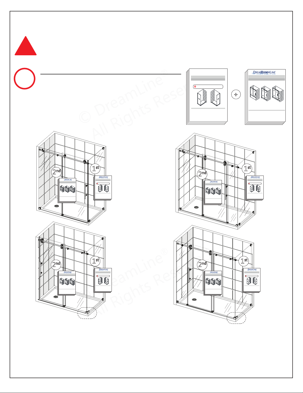
Please review this entire manual prior to installation.
ENIGMA-X/ENIGMA-XO Enclosure Return Panel
SHOWER ENCLOSURE RETURN PANEL INSTALLATION INSTRUCTIONS
IMPORTANT
DreamLine
®
reserves the right to alter, modify or redesign products at any time without prior notice.
For the latest up-to-date technical drawings, manuals, warranty information or additional details please refer
to your model’s web page on DreamLine.com
For more information about DreamLine
®
Shower Doors, Tub Doors & Enclosures, please visit DreamLine.com
©2018 DreamLine. All Rights Reserved
ENIGMA-X / ENIGMA-XO Shower Enclosure Return Panel manual Ver 1 01/2018
Right-Hand Return panel installation
Left-Hand Return panel installation
NOTE: Use this manual FIRST to install the Return Panel Glass.
Then use the manual packaged with the Door Glass box to continue
with the installation of the shower door section of the enclosure.
!
For the ENIGMA-XO Enclosure Installation:
Start with the Enigma-X/Enigma-XO
Enclosure Return Panel Manual that is
packaged with the return panel glass FIRST
for the installation of the return panel
glass, then use this manual for the
installation of the door section.
IMPORTANT! This manual will describe the installation of the single threshold
model of the Enigma-XO.
Use this manual when installing the Enigma-XO single threshold model.
+
!
For more information about DreamLine
®
Shower Doors & Tub Doors please visit DreamLine.com
ENIGMA-XO
SHDR-61727610-##
SHOWER DOOR INSTALLATION INSTRUCTIONS
IMPORTANT
DreamLine
®
reserves the right to alter, modify or redesign products at any time without prior notice.
For the latest up-to-date technical drawings, manuals, warranty information or additional details please refer
to your model’s web page on DreamLine.com
SHDR-61606210-## SHDR-61487610-##
SHDR-61607610-##
##=finish
07- Brushed Stainless Steel
08- Polished Stainless Steel
18- Tuxedo
ENIGMA-X shower and tub door manual Ver 6 Rev 7 06/2018
©2018 DreamLine. All Rights Reserved
Right-hand door installation shown
NOTE
2
nd
For more information about DreamLine
®
Shower Doors & Tub Doors please visit DreamLine.com
ENIGMA-XO
SHDR-61727610-##
SHOWER DOOR INSTALLATION INSTRUCTIONS
IMPORTANT
DreamLine
®
reserves the right to alter, modify or redesign products at any time without prior notice.
For the latest up-to-date technical drawings, manuals, warranty information or additional details please refer
to your model’s web page on DreamLine.com
SHDR-61606210-## SHDR-61487610-##
SHDR-61607610-##
##=finish
07- Brushed Stainless Steel
08- Polished Stainless Steel
18- Tuxedo
ENIGMA-X shower and tub door manual Ver 6 Rev 7 06/2018
©2018 DreamLine. All Rights Reserved
Right-hand door installation shown
2
nd
For more information about DreamLine
®
Shower Doors & Tub Doors please visit DreamLine.com
ENIGMA-XO
SHDR-61727610-##
SHOWER DOOR INSTALLATION INSTRUCTIONS
IMPORTANT
DreamLine
®
reserves the right to alter, modify or redesign products at any time without prior notice.
For the latest up-to-date technical drawings, manuals, warranty information or additional details please refer
to your model’s web page on DreamLine.com
SHDR-61606210-## SHDR-61487610-##
SHDR-61607610-##
##=finish
07- Brushed Stainless Steel
08- Polished Stainless Steel
18- Tuxedo
ENIGMA-X shower and tub door manual Ver 6 Rev 7 06/2018
©2018 DreamLine. All Rights Reserved
Right-hand door installation shown
2
nd
For more information about DreamLine
®
Shower Doors & Tub Doors please visit DreamLine.com
ENIGMA-XO
SHDR-61727610-##
SHOWER DOOR INSTALLATION INSTRUCTIONS
IMPORTANT
DreamLine
®
reserves the right to alter, modify or redesign products at any time without prior notice.
For the latest up-to-date technical drawings, manuals, warranty information or additional details please refer
to your model’s web page on DreamLine.com
SHDR-61606210-## SHDR-61487610-##
SHDR-61607610-##
##=finish
07- Brushed Stainless Steel
08- Polished Stainless Steel
18- Tuxedo
ENIGMA-X shower and tub door manual Ver 6 Rev 7 06/2018
©2018 DreamLine. All Rights Reserved
Right-hand door installation shown
2
nd
For more information about DreamLine
®
Shower Doors & Tub Doors please visit DreamLine.com
ENIGMA-XO
SHDR-61727610-##
SHOWER DOOR INSTALLATION INSTRUCTIONS
IMPORTANT
DreamLine
®
reserves the right to alter, modify or redesign products at any time without prior notice.
For the latest up-to-date technical drawings, manuals, warranty information or additional details please refer
to your model’s web page on DreamLine.com
SHDR-61606210-## SHDR-61487610-##
SHDR-61607610-##
##=finish
07- Brushed Stainless Steel
08- Polished Stainless Steel
18- Tuxedo
ENIGMA-X shower and tub door manual Ver 6 Rev 7 06/2018
©2018 DreamLine. All Rights Reserved
Right-hand door installation shown
Please review this entire manual prior to installation.
ENIGMA-X/ENIGMA-XO Enclosure Return Panel
SHOWER ENCLOSURE RETURN PANEL INSTALLATION INSTRUCTIONS
IMPORTANT
DreamLine
®
reserves the right to alter, modify or redesign products at any time without prior notice.
For the latest up-to-date technical drawings, manuals, warranty information or additional details please refer
to your model’s web page on DreamLine.com
For more information about DreamLine
®
Shower Doors, Tub Doors & Enclosures, please visit DreamLine.com
©2018 DreamLine. All Rights Reserved
ENIGMA-X / ENIGMA-XO Shower Enclosure Return Panel manual Ver 1 01/2018
Right-Hand Return panel installation
Left-Hand Return panel installation
NOTE: Use this manual FIRST to install the Return Panel Glass.
Then use the manual packaged with the Door Glass box to continue
with the installation of the shower door section of the enclosure.
!
1
st
Please review this entire manual prior to installation.
ENIGMA-X/ENIGMA-XO Enclosure Return Panel
SHOWER ENCLOSURE RETURN PANEL INSTALLATION INSTRUCTIONS
IMPORTANT
DreamLine
®
reserves the right to alter, modify or redesign products at any time without prior notice.
For the latest up-to-date technical drawings, manuals, warranty information or additional details please refer
to your model’s web page on DreamLine.com
For more information about DreamLine
®
Shower Doors, Tub Doors & Enclosures, please visit DreamLine.com
©2018 DreamLine. All Rights Reserved
ENIGMA-X / ENIGMA-XO Shower Enclosure Return Panel manual Ver 1 01/2018
Right-Hand Return panel installation
Left-Hand Return panel installation
NOTE: Use this manual FIRST to install the Return Panel Glass.
Then use the manual packaged with the Door Glass box to continue
with the installation of the shower door section of the enclosure.
!
1
st
Please review this entire manual prior to installation.
ENIGMA-X/ENIGMA-XO Enclosure Return Panel
SHOWER ENCLOSURE RETURN PANEL INSTALLATION INSTRUCTIONS
IMPORTANT
DreamLine
®
reserves the right to alter, modify or redesign products at any time without prior notice.
For the latest up-to-date technical drawings, manuals, warranty information or additional details please refer
to your model’s web page on DreamLine.com
For more information about DreamLine
®
Shower Doors, Tub Doors & Enclosures, please visit DreamLine.com
©2018 DreamLine. All Rights Reserved
ENIGMA-X / ENIGMA-XO Shower Enclosure Return Panel manual Ver 1 01/2018
Right-Hand Return panel installation
Left-Hand Return panel installation
NOTE: Use this manual FIRST to install the Return Panel Glass.
Then use the manual packaged with the Door Glass box to continue
with the installation of the shower door section of the enclosure.
!
1
st
Please review this entire manual prior to installation.
ENIGMA-X/ENIGMA-XO Enclosure Return Panel
SHOWER ENCLOSURE RETURN PANEL INSTALLATION INSTRUCTIONS
IMPORTANT
DreamLine
®
reserves the right to alter, modify or redesign products at any time without prior notice.
For the latest up-to-date technical drawings, manuals, warranty information or additional details please refer
to your model’s web page on DreamLine.com
For more information about DreamLine
®
Shower Doors, Tub Doors & Enclosures, please visit DreamLine.com
©2018 DreamLine. All Rights Reserved
ENIGMA-X / ENIGMA-XO Shower Enclosure Return Panel manual Ver 1 01/2018
Right-Hand Return panel installation
Left-Hand Return panel installation
NOTE: Use this manual FIRST to install the Return Panel Glass.
Then use the manual packaged with the Door Glass box to continue
with the installation of the shower door section of the enclosure.
!
1
st
© DreamLine
®
All Rights Reserved
© DreamLine
®
All Rights Reserved
Important Model Information
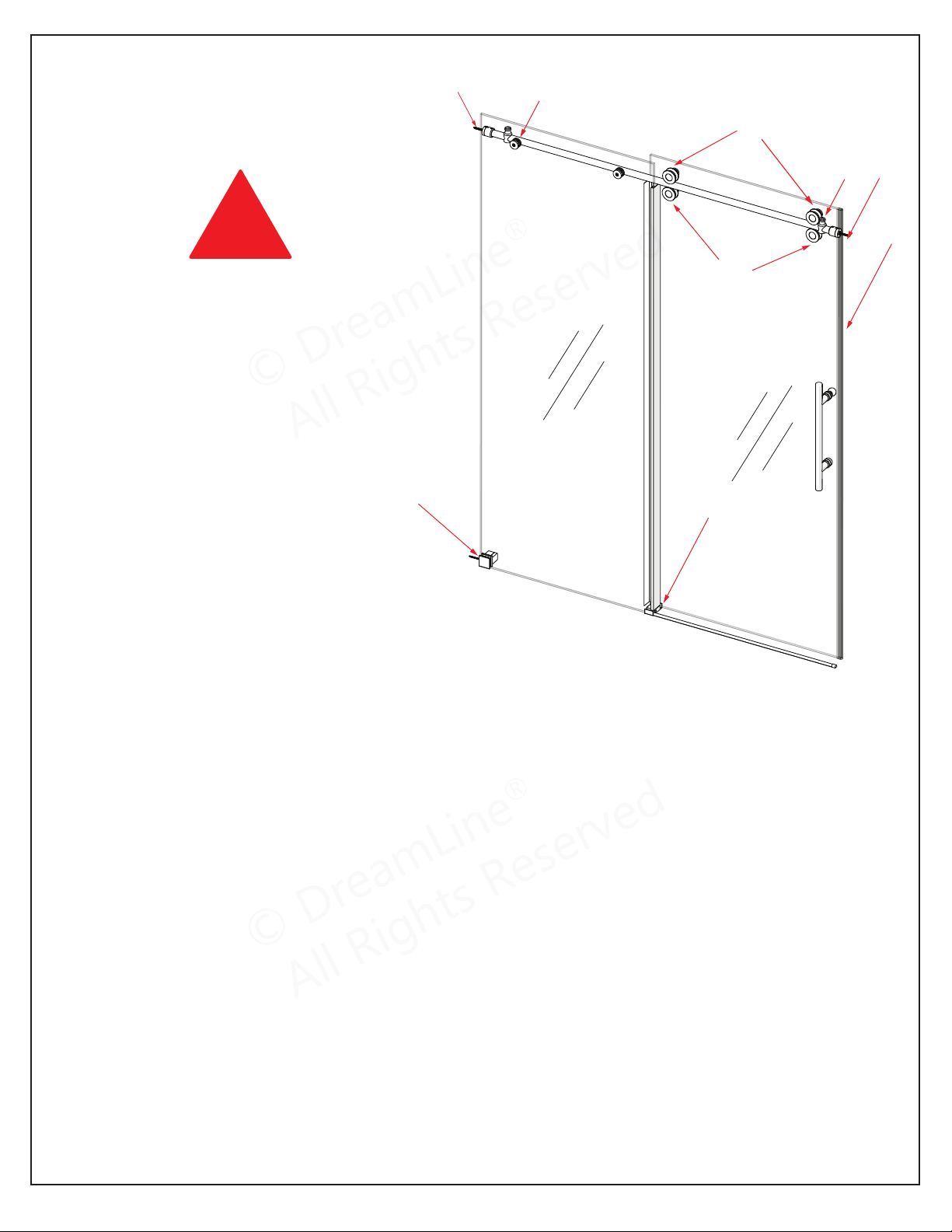
A
Guide Rail Brackets must be firmly
attached to the wall. Installation into a
stud is strongly recommended.
All of the guide rail bracket set screws
must be accessible and tightened.
B
Thread Lock must be applied to the
set screws in both stoppers.
Panel-side stopper must be installed
into the pre-drilled stopper hole in
the upper guide rail.
Door-side stopper must be installed
at the proper position to prevent the
door from contacting the wall.
E
Bulb Vinyl Seal must be installed on the
closing edge of the Door Glass.
D
Lower Roller Wheel Assemblies must be
adjusted during installation to make
contact with the Upper Guide Rail.
Tighten safety set screws. Apply thread
lock.
F
The Guide Block must be screwed to the
threshold and installed square with the Panel
Glass and Door Glass. Installing the guide
block crooked may damage the bottom edge
of the Door Glass and lead to breakage.
C
Roller Wheel Assembly safety set
screws: must be accessible and must
be retightened with Thread Lock
during installation.
PLEASE READ THE ENCLOSED INSTALLATION
MANUAL FOR DETAILS REGARDING PROPER
INSTALLATION.
THE LATEST VERSION OF THE INSTALLATION
MANUAL IS AVAILABLE TO VIEW OR PRINT ON
DREAMLINE.COM
G
SafeStop™ Bumper must be secured in
position with 3M™ tape or screwed to the wall.
IMPORTANT INFORMATION
REGARDING THE INSTALLATION
OF THIS SHOWER DOOR
ENIGMA-XO Shower and Tub Door Manual Ver 1 Rev 3 062019 4
©2019 DreamLine
®
All Rights Reserved
*Right-hand door installation shown
A
A
B
B
D
G
F
E
C
!
© DreamLine
®
All Rights Reserved
© DreamLine
®
All Rights Reserved
Recommended Reinforcement Information
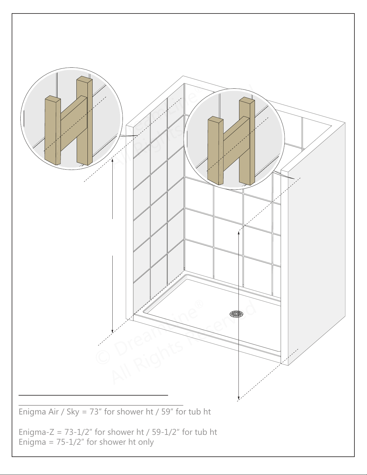
Install studs OR install 2”x 6” wood blocking between the studs where
the Guide Rail Brackets will attach to the wall
*Blocking height requirement (to center)
as measured from the threshold or tub deck:
Enigma Air / Sky = 73” for shower ht / 59” for tub ht
Enigma-X / XO = 72-1/2“ for shower ht / 58-1/2” for tub ht
Enigma-Z = 73-1/2” for shower ht / 59-1/2“ for tub ht
Enigma = 75-1/2” for shower ht only
ENIGMA-XO Shower and Tub Door Manual Ver 1 Rev 3 062019 5
©2019 DreamLine
®
All Rights Reserved
measure from
threshold*
(see list below)
threshold
or tub deck
threshold
or tub deck
2”×6”
2”×6”
© DreamLine
®
All Rights Reserved
© DreamLine
®
All Rights Reserved
Model Specific Preparation
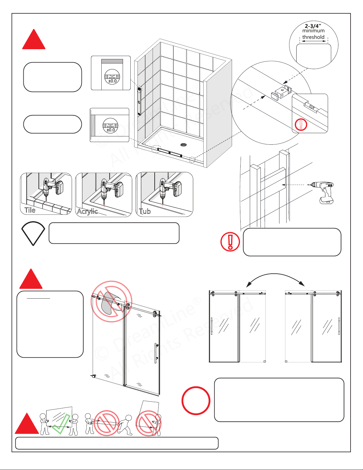
REQUIRED:
!
ENIGMA-XO Shower and Tub Door Manual Ver 1 Rev 3 062019 6
©2019 DreamLine
®
All Rights Reserved
Contact the manufacturer of the base, tub or threshold
material with any questions regarding the drilling of
holes into their product.
R
L
DO NOT hang or
drape a towel or wash
cloth over the Enigma
series guide rail as
this may cause the
roller assemblies to
get stuck and possibly
cause serious damage
or injury.
This model is reversible for right or left-hand door
installation. The right-hand door installation is
shown as an example throughout this manual. For
the left-hand door installation, simply begin on
the opposite wall and reverse the orientation of
the steps shown.
This door requires professional installation. Two installers recommended.
!
!
Door Door
Panel Panel
No Out-of-Plumb
Adjustment; Verify
threshold and walls
with a level
Threshold must be
level
2-3/4”
minimum
threshold
!
Threshold must be level
2-3/4”
minimum
threshold
±
0
.0
±
0
.0
Tile
Acrylic Tub
Drilling into a stud or 2×6 wood
reinforcement is recommended.
*see page 5 for more information
2” X 6”
!
TIP
NOTE
±
0
.0
±
0
.0
© DreamLine
®
All Rights Reserved
© DreamLine
®
All Rights Reserved
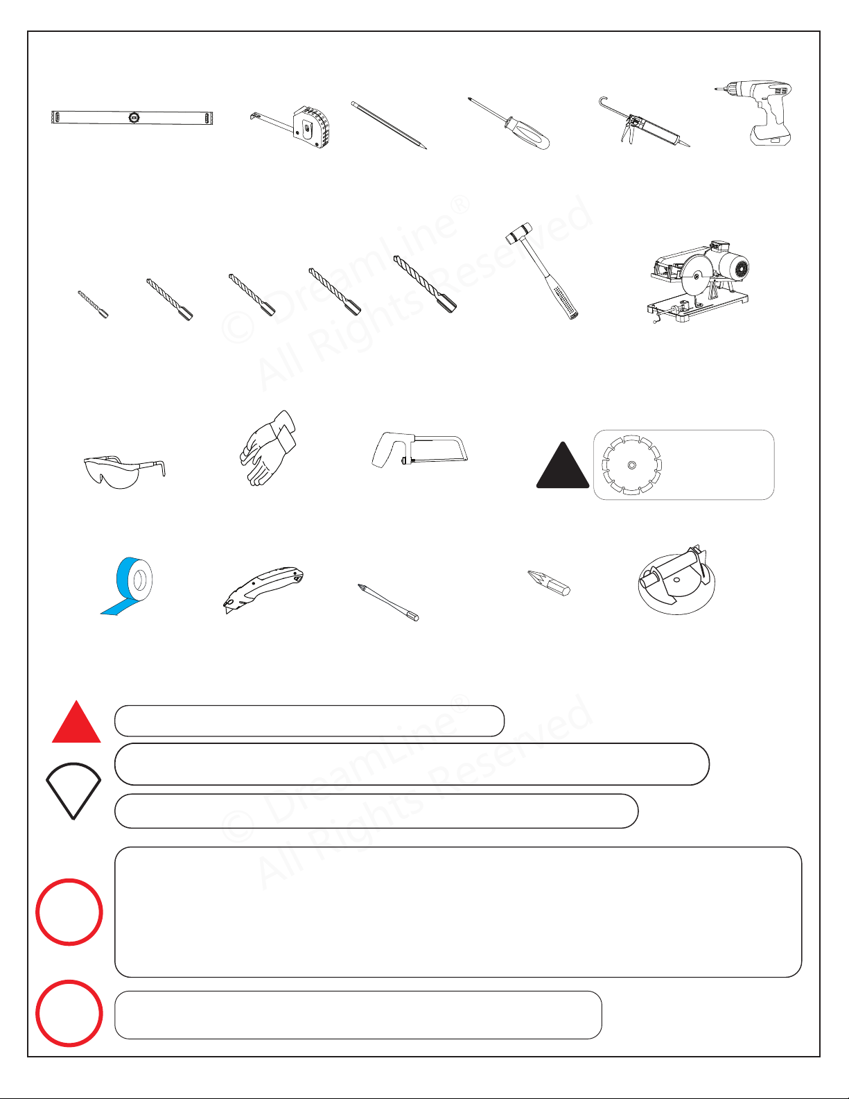
Tools
Be sure to cover the shower drain to prevent losing small parts.
Unpack your unit carefully and inspect it. Lay it out and identify all parts using the Detailed
Diagram(s) on pages 8 and 11; and packing list in this manual as a reference. Before
discarding the carton, check for small hardware bags that may have fallen to the bottom of
the box. If any parts are damaged or missing, please contact DreamLine
®
for replacement.
The shipping boxes may contain extra parts not used in your model configuration.
Retain these installation instructions for future reference.
Measure the finished opening before proceeding with the installation
to be sure that the correct model size has been ordered.
Threshold must be level; Walls must be plumb.
These instructions will show the installation of the shower door.
Please follow the same steps for the installation of the tub door.
ENIGMA-XO Shower and Tub Door Manual Ver 1 Rev 3 062019 7
©2019 DreamLine
®
All Rights Reserved
Soft Head
Hammer
Ø1/8"
(3mm)
Drill Bit
Drill Bit
Ø5/16"
(8mm)
Ø1/4"
(6mm)
Drill Bit
Chop saw**
Professional-grade
Glass suction cup
Extender Driver Bit
#3 Phillips
Driver Bit
**Use the proper
saw blade to cut
stainless steel.
!
Level
Measure
Tape
Pencil
Drill
Power
Razor Knife
Painter’s Tape
Phillips
Screwdriver
Silicone
Hacksaw**
Work Gloves
Ø3/16"
(4mm)
Drill Bit
Drill Bit
Ø3/8"
(10mm)
Safety Glasses
NOTE
NOTE
!
TIP
© DreamLine
®
All Rights Reserved
© DreamLine
®
All Rights Reserved
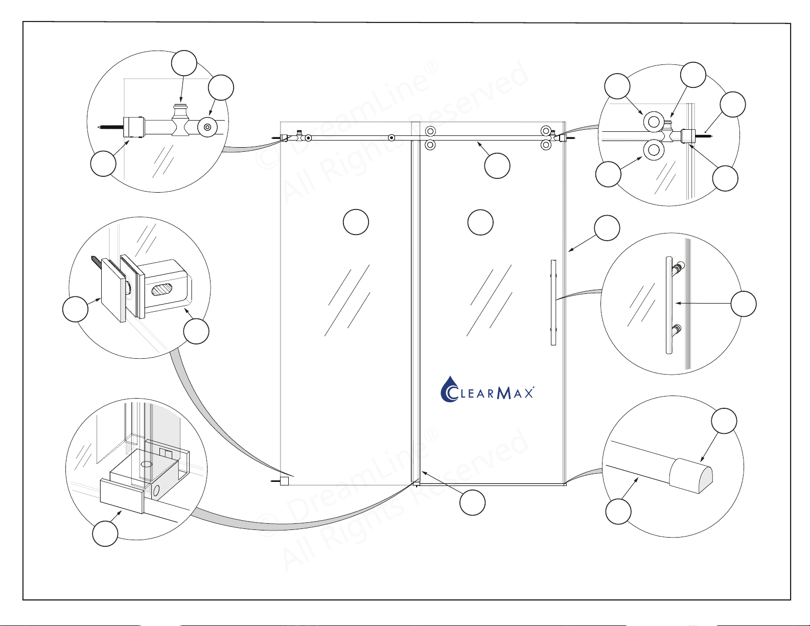
Detailed Diagram ‘A’ of Shower Door Components
for Model #
SHDR-61487620-##
SHDR-61547620-##
SHDR-61606220-##
SHDR-61607620-##
ENIGMA-XO Shower and Tub Door Manual Ver 1 Rev 3 062019 8
© 2019 DreamLine® All Rights Reserved
05
02
Panel Glass
Door Glass
The glass surface
with the ClearMax™
label must be
installed to face
inside of the shower
*Right-hand door installation shown.
01
07
08
03
04
04
08
10
01
06
15
16
14
12
13
19
30
© DreamLine
®
All Rights Reserved
© DreamLine
®
All Rights Reserved
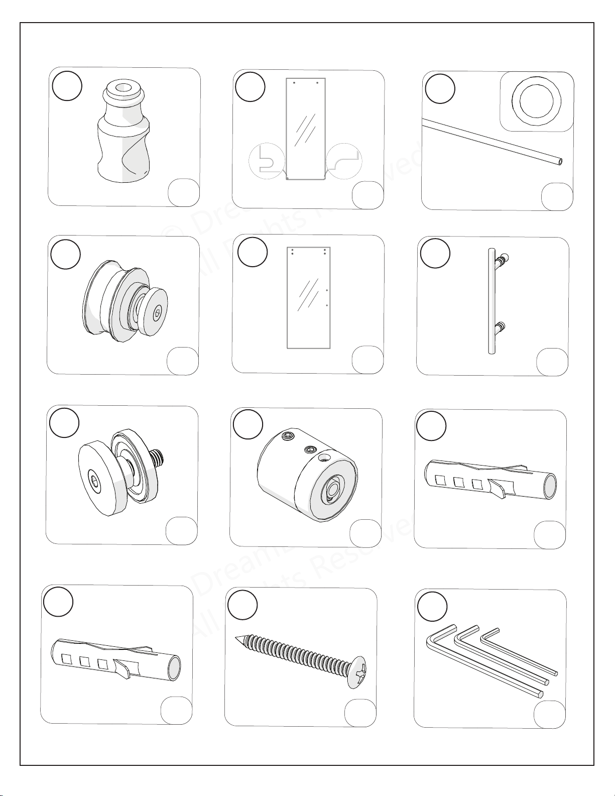
Parts List A
ENIGMA-XO Shower and Tub Door Manual Ver 1 Rev 3 062019 9
©2019 DreamLine
®
All Rights Reserved
Top Guide Rail (for 48” or 60”)
Roller Assembly Door Glass
Handle
Glass-to-Rail Bracket
Guide Rail Bracket
Wall Anchor Ø3/8” (10mm)
Wall Anchor Ø5/16” (8mm)
ST6×55
Large Truss Head Screw
Allen Wrench (3,4,5 mm)
Door Stopper Panel Glass
04
05
03
06
07
08
09a
09b
10
11
01
02
x2
x2
x4
x1
x1
x1
x1
x2
x2
x3
x2
x1set
© DreamLine
®
All Rights Reserved
© DreamLine
®
All Rights Reserved
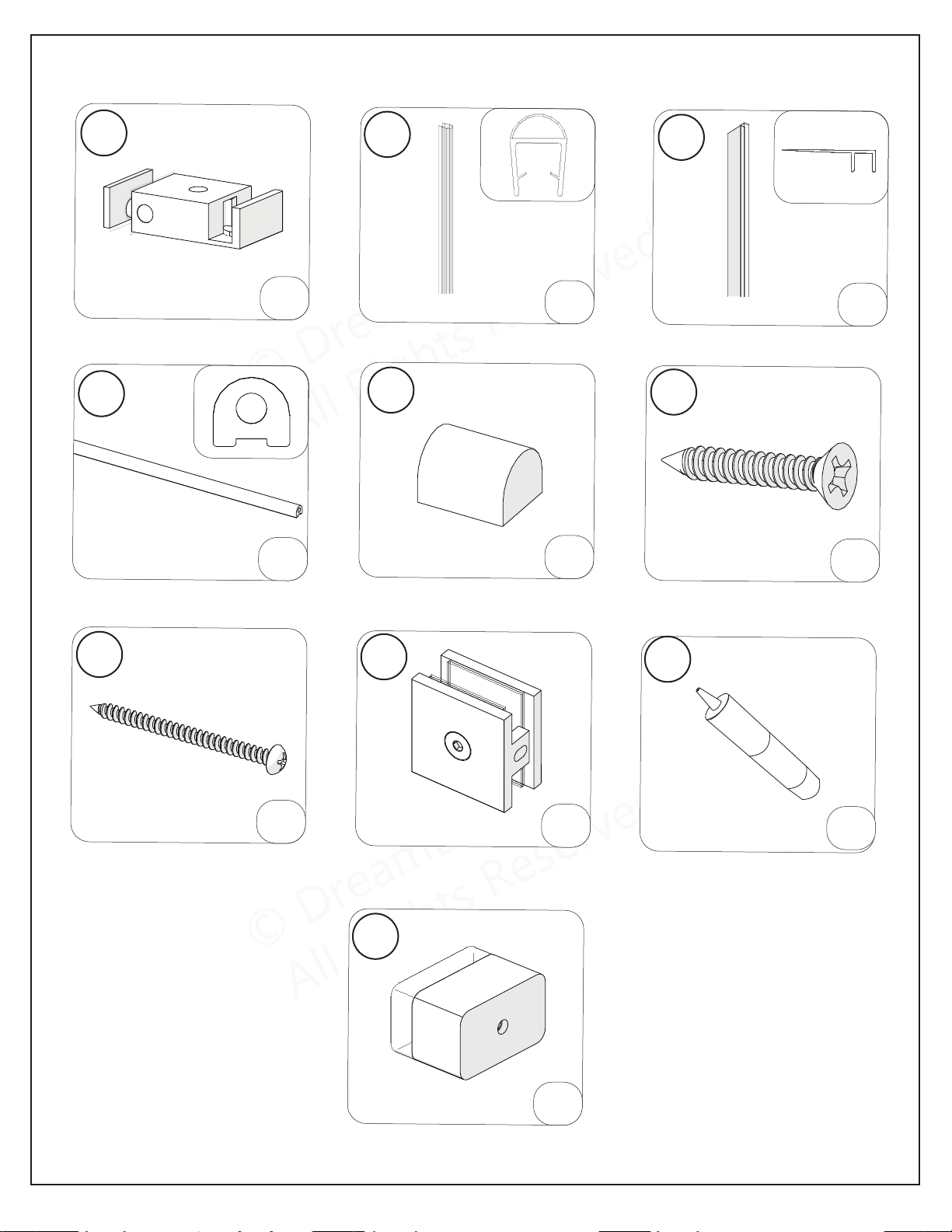
Parts List
ENIGMA-XO Shower and Tub Door Manual Ver 1 Rev 3 062019 10
©2019 DreamLine
®
All Rights Reserved
Vertical Vinyl Strip
Dam Strip
Dam Strip End Cap
ST4.2×40mm
Countersunk Screw
ST4.2×55
Truss Head Screw
Wall Bracket
Thread Lock Adhesive
SafeStop™ Bumper
Guide Block (with caps)
Bulb Vinyl Strip
15
16
14
17
18
19
26
30
12
13
x1
x1
x1
x1
x2
x1
x2
x1
x1
x1
© DreamLine
®
All Rights Reserved
© DreamLine
®
All Rights Reserved
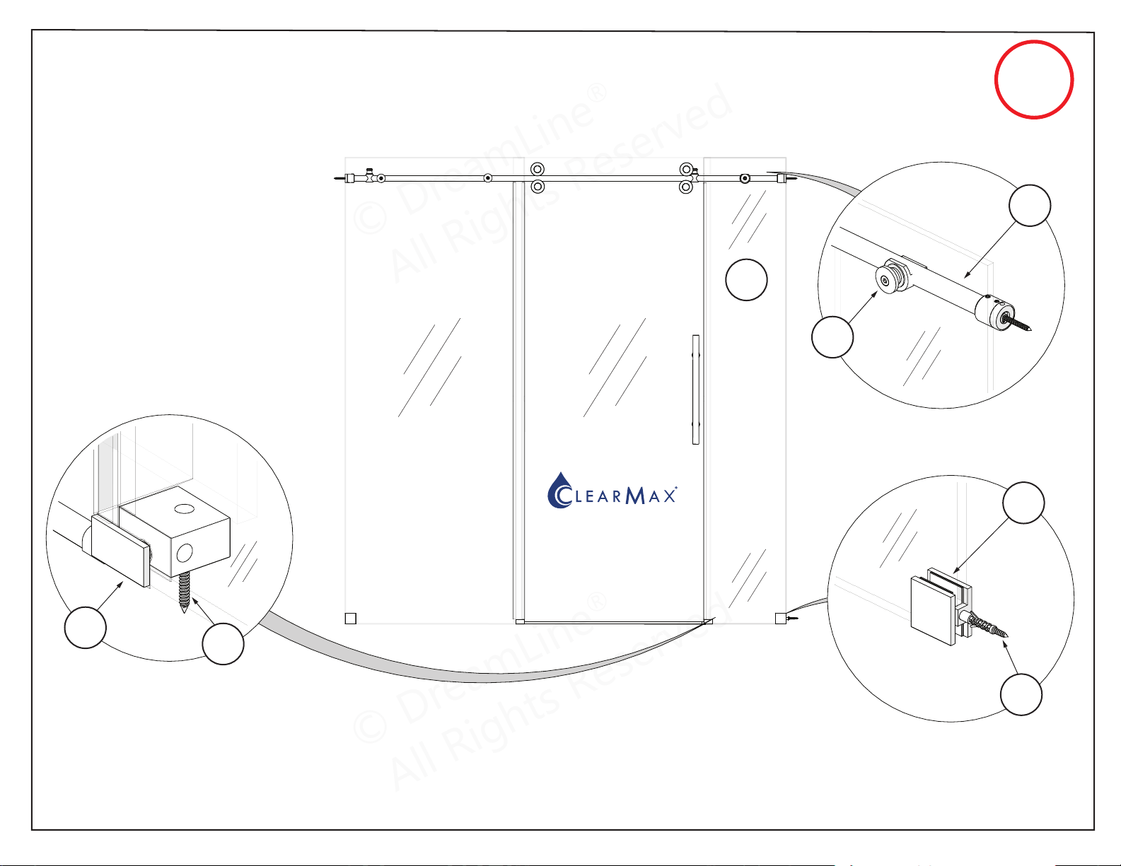
Detailed Diagram ‘B’ of Shower Door Components
for Model # (for 72”)
SHDR-61727620-##
ENIGMA-XO Shower and Tub Door Manual Ver 1 Rev 3 062019 11
© 2019 DreamLine® All Rights Reserved
72”
MODEL
ONLY
Panel Glass
Door Glass
The glass surface
with the ClearMax™
label must be
installed to face
inside of the shower
Small Inline
Panel Glass
*Right-hand door installation shown.
22
25
23
21
24
18
19
© DreamLine
®
All Rights Reserved
© DreamLine
®
All Rights Reserved
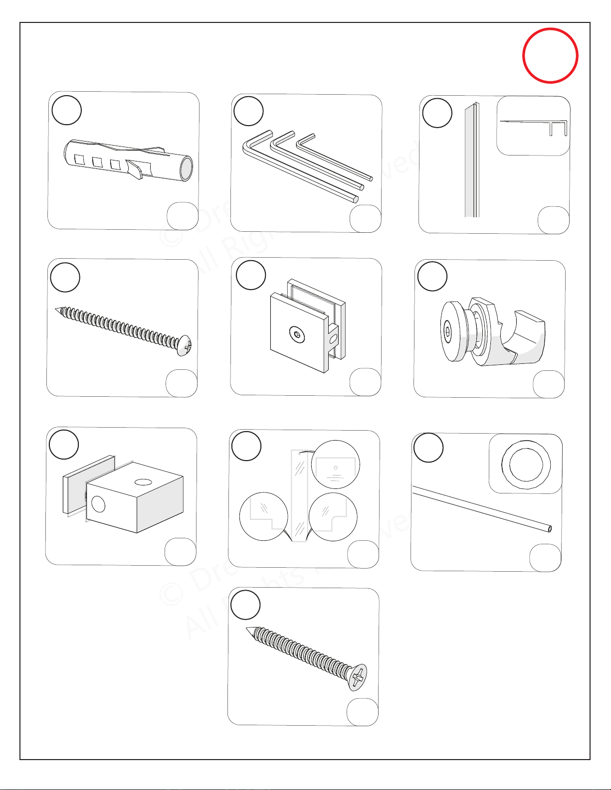
Parts List B
ENIGMA-XO Shower and Tub Door Manual Ver 1 Rev 3 062019 12
©2019 DreamLine
®
All Rights Reserved
72”
MODEL
ONLY
Vertical Vinyl Strip
ST4.2×55
Truss Head Screw
Wall Bracket
Glass-to-Rail Bracket
Small Inline Panel Glass
Bottom Bracket
Small Inline Panel Glass
Top Guide Rail
(for 72”)
ST4.2×40
Countersunk Screw
Allen Wrench (3,4,5mm)
18
19
14
21
22
23
24
25
09b
11
x2
x1
x1
x1set
x1
x1
x1
x1
x1
x1
Wall Anchor Ø5/16” (8mm)
© DreamLine
®
All Rights Reserved
© DreamLine
®
All Rights Reserved
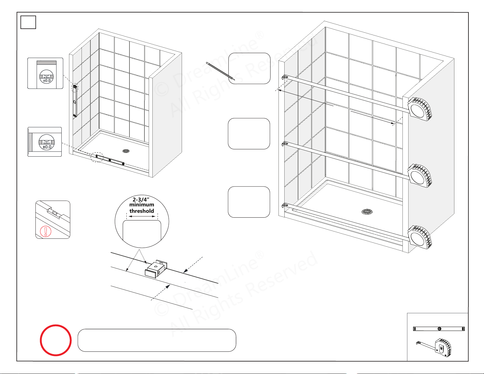
Installation Steps
Tools Needed
ENIGMA-XO Shower and Tub Door Manual Ver 1 Rev 3 062019 13
© 2019 DreamLine® All Rights Reserved
Middle
Bottom
Top
*at model height
________”
________”
________”
±
0
.0
±
0
.0
1
NOTE
The minimum threshold requirement for the
ENIGMA-XO is 2-3/4” of flat threshold space.
±
0
.0
±
0
.0
W
Threshold must be level
!
2-3/4”
minimum
2-3/4”
minimum
threshold
© DreamLine
®
All Rights Reserved
© DreamLine
®
All Rights Reserved
Tools Needed
Parts Needed
ENIGMA-XO Shower and Tub Door Manual Ver 1 Rev 3 062019 14
© 2019 DreamLine® All Rights Reserved
2
Fig 2
!
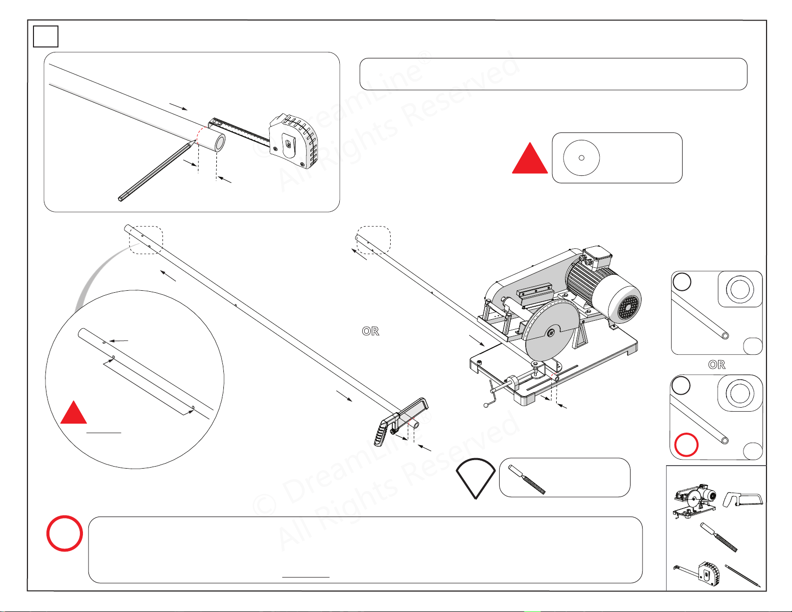
**Use the proper
saw blade to cut
stainless steel.
(L)
Door End
(no holes)
TIP
Use a metal file
to deburr the
cut end
OR
Door End
Panel End
(L)
Door End
Panel End
(L)
Panel End
Door Stopper (#01)
hole
Glass-to-Rail Bracket (#07)
holes
!
DO NOT cut from the
Panel End of the
Top Guide Rail (#03).
NOTE
The Top Guide Rail (#03) has been pre-cut for the model width of: 48”, 54”, 60”, 72”.
(The actual rail is shorter than the model width by design to account for the guide rail brackets.)
Cut the Top Guide Rail (#03) from the door end only, which is the end that is farther from the
Glass-to-Rail Bracket (#07) holes. DO NOT cut the panel end of the Top Guide Rail (#03).
03
x1
24
x1
72”
MODEL
ONLY
OR
The length to cut-off from the door side of the Top Guide Rail (#03) will be (L):
Model Width (-) Finished Opening (W) = Cut-off Length (L)
© DreamLine
®
All Rights Reserved
© DreamLine
®
All Rights Reserved
Tools Needed
Parts Needed
ENIGMA-XO Shower and Tub Door Manual Ver 1 Rev 3 062019 15
© 2019 DreamLine® All Rights Reserved
3
03
07
08
11
19
01
x2
x2
02
x1
x1
x2
x1set
x1
Fig 3
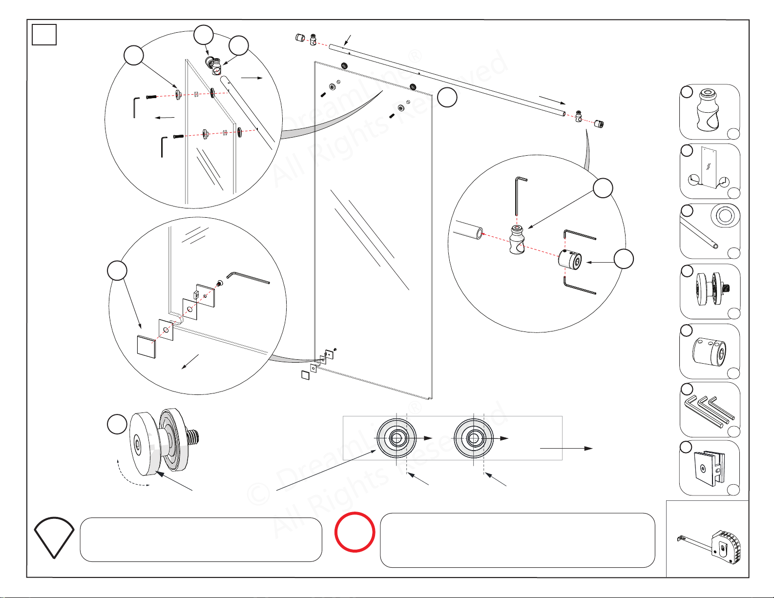
TIP
Door end of guide rail
High spot of Adjustment Disk bushing
NOTE
Glass-to-Rail Bracket
Adjustment disk
07
Panel-end Door Stopper (#01) hole
outside
inside
door end
outside
Inline Panel Glass
01
01
19
08
07
07
08
Find and mark the location of the high spot on
the outer surface of the adjustment disk with a
felt tip pen to make adjustment easier to see.
The outer Glass-to-Rail Bracket (#07) disk has an
eccentric bushing for adjustment. Be sure to install both
Glass-to-Rail Bracket disks with the high spot of the
bushing pointed towards the door end of the guide rail.
© DreamLine
®
All Rights Reserved
© DreamLine
®
All Rights Reserved
Parts Needed
ENIGMA-XO Shower and Tub Door Manual Ver 1 Rev 3 062019 16
© 2019 DreamLine® All Rights Reserved
4
72”
MODEL
ONLY
NOTE
Loosen the screw on the rear of the
Glass-to-Rail Bracket (#21) with the supplied
allen wrench and secure it to the Top Guide
Rail (#24). It is NOT neccessary to fully
dissassemble the bracket during installation.
21
x1
6-5/8”
from wall
Fig 4
Inline Panel Glass
© DreamLine
®
All Rights Reserved
© DreamLine
®
All Rights Reserved
Tools Needed
ENIGMA-XO Shower and Tub Door Manual Ver 1 Rev 3 062019 17
© 2019 DreamLine® All Rights Reserved
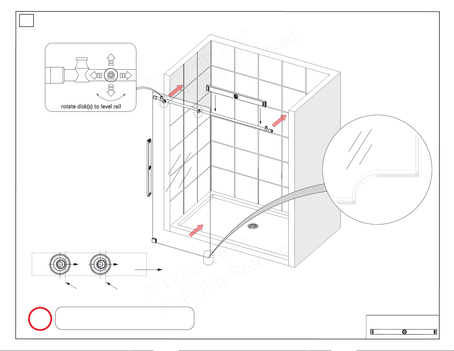
rotate disk(s) to level rail
Door end of guide rail
High spot of Adjustment Disk bushing
NOTE
The Panel Glass (#02) must be installed to
the outside of the Top Guide Rail (#03).
5
© DreamLine
®
All Rights Reserved
© DreamLine
®
All Rights Reserved
Parts Needed
ENIGMA-XO Shower and Tub Door Manual Ver 1 Rev 3 062019 18
© 2019 DreamLine® All Rights Reserved
72”
MODEL
ONLY
6
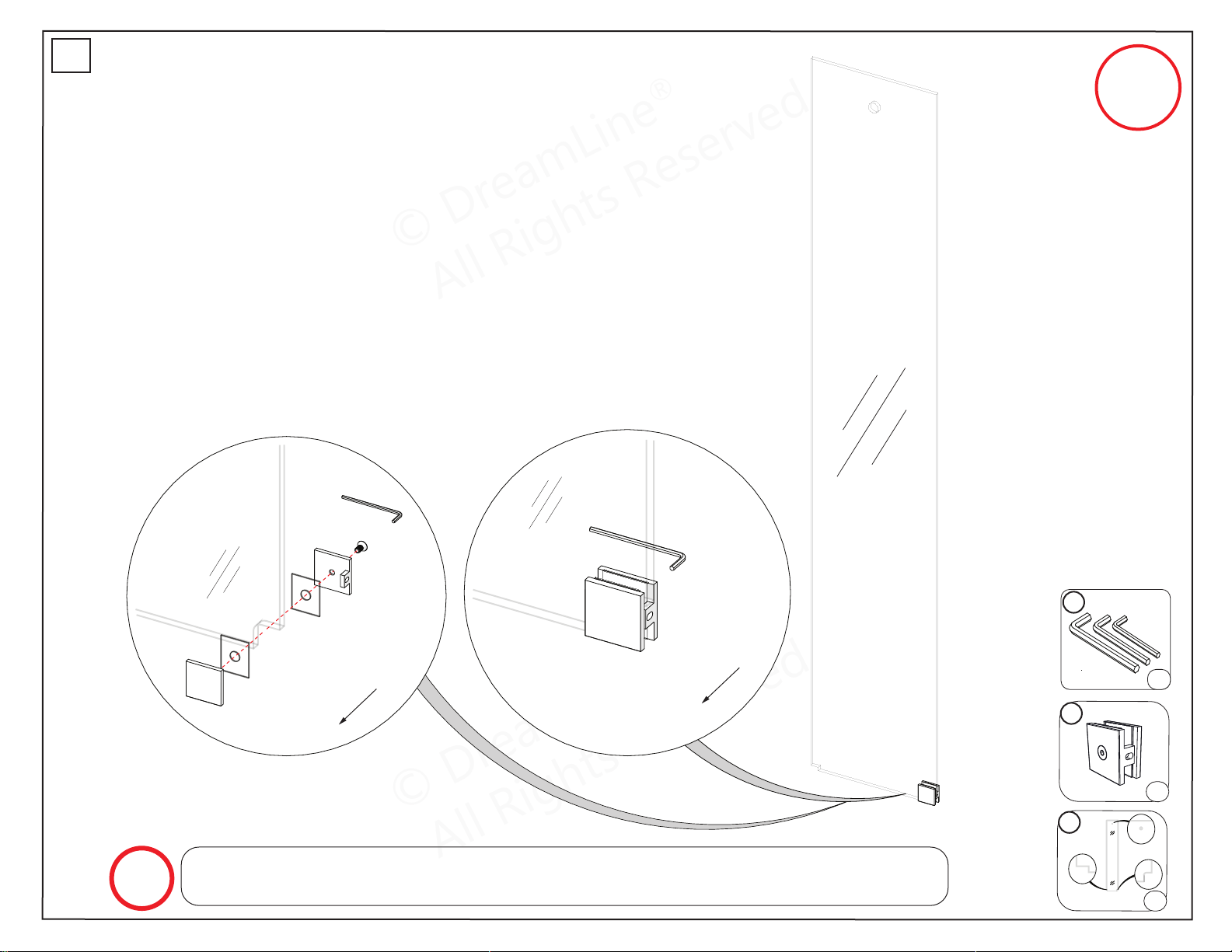
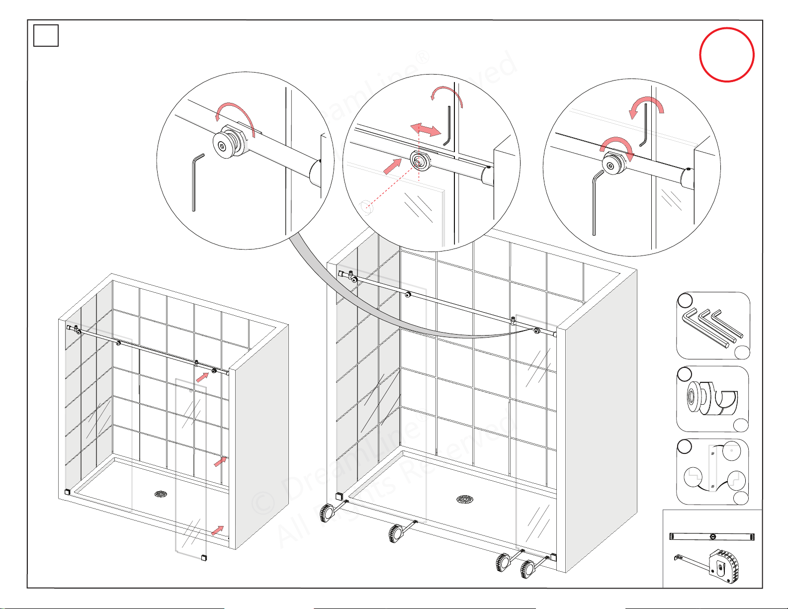
For single threshold installation (shown), this bracket will be installed into the wall.
For an enclosure installation only, this bracket will need to be installed into the threshold.
NOTE
11
x1set
19
x1
23
x1
outside
outside
© DreamLine
®
All Rights Reserved
© DreamLine
®
All Rights Reserved
Tools Needed
Parts Needed
ENIGMA-XO Shower and Tub Door Manual Ver 1 Rev 3 062019 19
© 2019 DreamLine® All Rights Reserved
Fig 7a
Fig 7b
7
21
x1
23
x1
11
x1set
72”
MODEL
ONLY
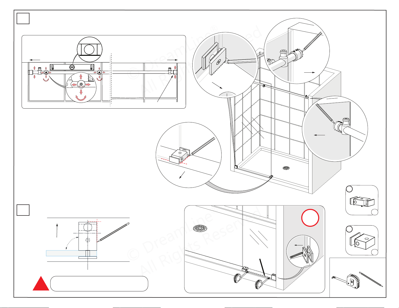
1 2 3
© DreamLine
®
All Rights Reserved
© DreamLine
®
All Rights Reserved
Tools Needed
Parts Needed
*72” Model Only
ENIGMA-XO Shower and Tub Door Manual Ver 1 Rev 3 062019 20
© 2019 DreamLine® All Rights Reserved
Fig 8a
Fig 8b
Panel end Door end
Glass-to-Rail Bracket (#07) Guide Rail Bracket (#08)
*Right-hand door installation shown.
Fig 9
inside
72”
MODEL
ONLY
22
x1
x1
12
8
9
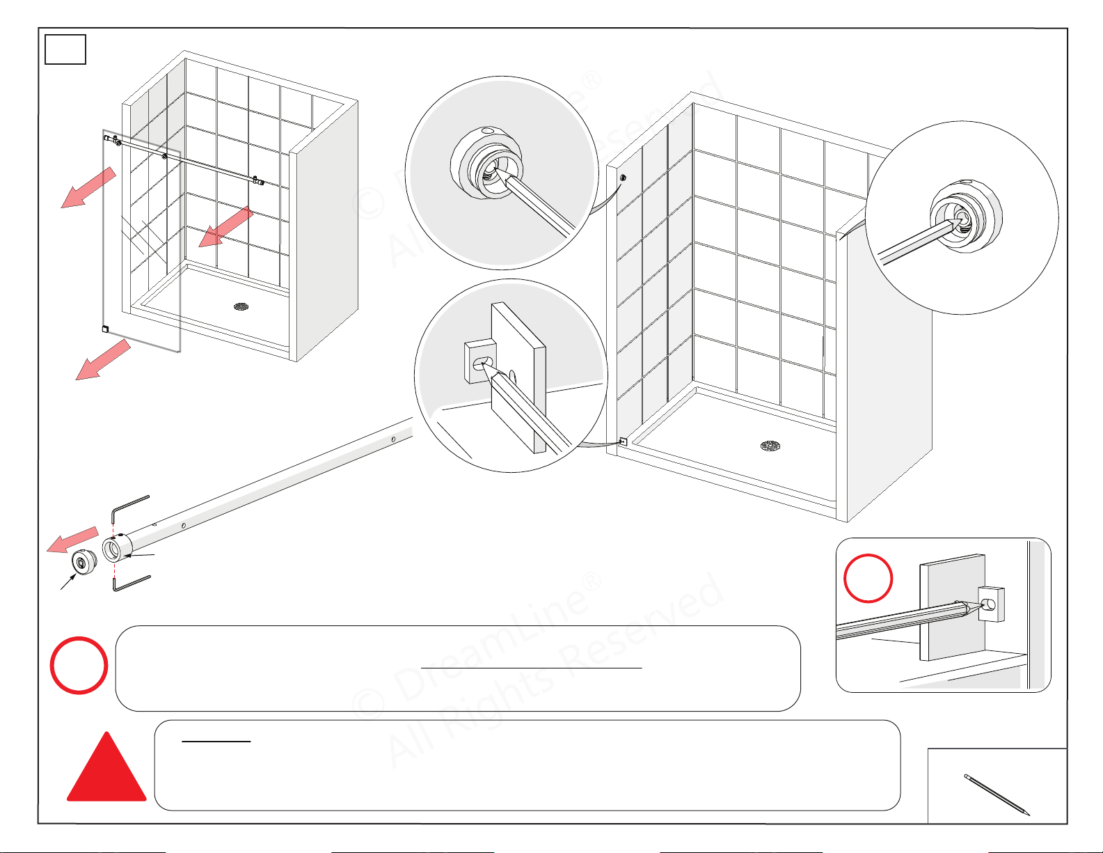
Guide Block (#12) must be installed
square to the plane of the glass.
!
outside
inside
inside
inside
overhead view of threshold & guide block
90°
inside
Inline Panel glass
© DreamLine
®
All Rights Reserved
© DreamLine
®
All Rights Reserved
Tools Needed
ENIGMA-XO Shower and Tub Door Manual Ver 1 Rev 3 062019 21
© 2019 DreamLine® All Rights Reserved
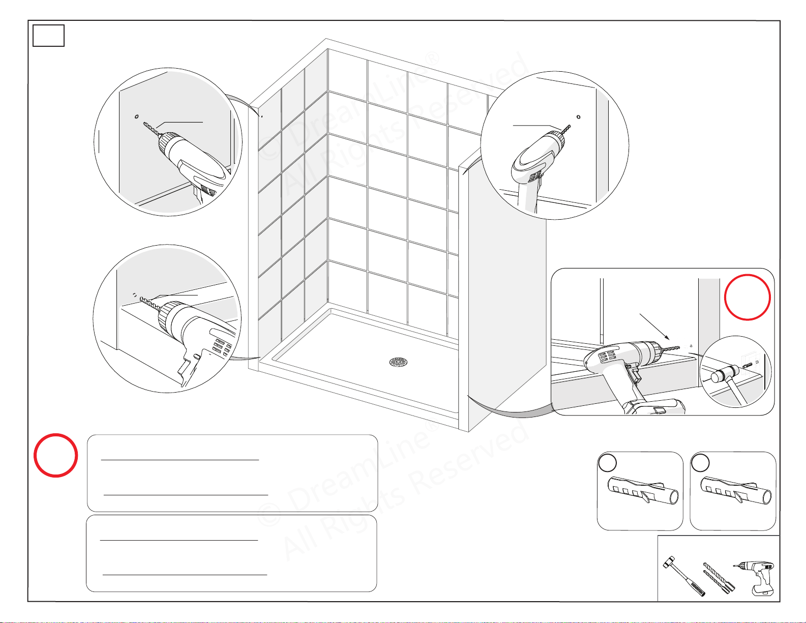
**Step #11 has an option for installing the guide rail brackets to the wall using anchors. However,
the manufacturer strongly recommends installing the guide rail brackets into studs or to
pre-installed 2”x 6“ wood reinforcements behind the wall in the area where the guide rail
brackets will be attached to the wall.
!
Fig 10a
base
sleeve
Fig 10b
72”
MODEL
ONLY
10
Fig 10c
Separate the Guide Rail Bracket (#08) base from the sleeve by loosening the set screws. Leave the
sleeves on both ends of the Top Guide Rail. For enclosure installation only: remove the Guide
Rail Bracket (#08) base on the side that will meet the Return Panel and refer to the
Enigma-X/Enigma-XO Enclosure Return Panel Manual.
NOTE
© DreamLine
®
All Rights Reserved
© DreamLine
®
All Rights Reserved
Tools Needed
Parts Needed
ENIGMA-XO Shower and Tub Door Manual Ver 1 Rev 3 062019 22
© 2019 DreamLine® All Rights Reserved
09b
09a
72”
MODEL
ONLY
Fig 11
11
For Guide Rail Brackets:
◾If a stud is present behind the wall:
drill a Ø1/4”(6mm) hole up to the stud. (recommended)
OR
◾If no stud is present behind the wall:
drill a Ø3/8”(7mm) hole and install the Wall Anchor (#09a).
For Wall Brackets:
◾If a stud is present behind the wall:
drill a Ø3/16”(4mm) hole up to the stud.
OR
◾If no stud is present behind the wall:
drill a Ø5/16”(10mm) hole and install the Wall Anchor (#09b).
NOTE
Ø3/8” or
Ø1/4”
drill bit
Ø3/8” or
Ø1/4”
drill bit
*see NOTE
*see NOTE
Ø3/16” or
Ø5/16”
drill bit
*see NOTE
Ø3/16” or
Ø5/16”
drill bit
*see NOTE

© DreamLine
®
All Rights Reserved
© DreamLine
®
All Rights Reserved
Tools Needed
Parts Needed
ENIGMA-XO Shower and Tub Door Manual Ver 1 Rev 3 062019 23
© 2019 DreamLine® All Rights Reserved
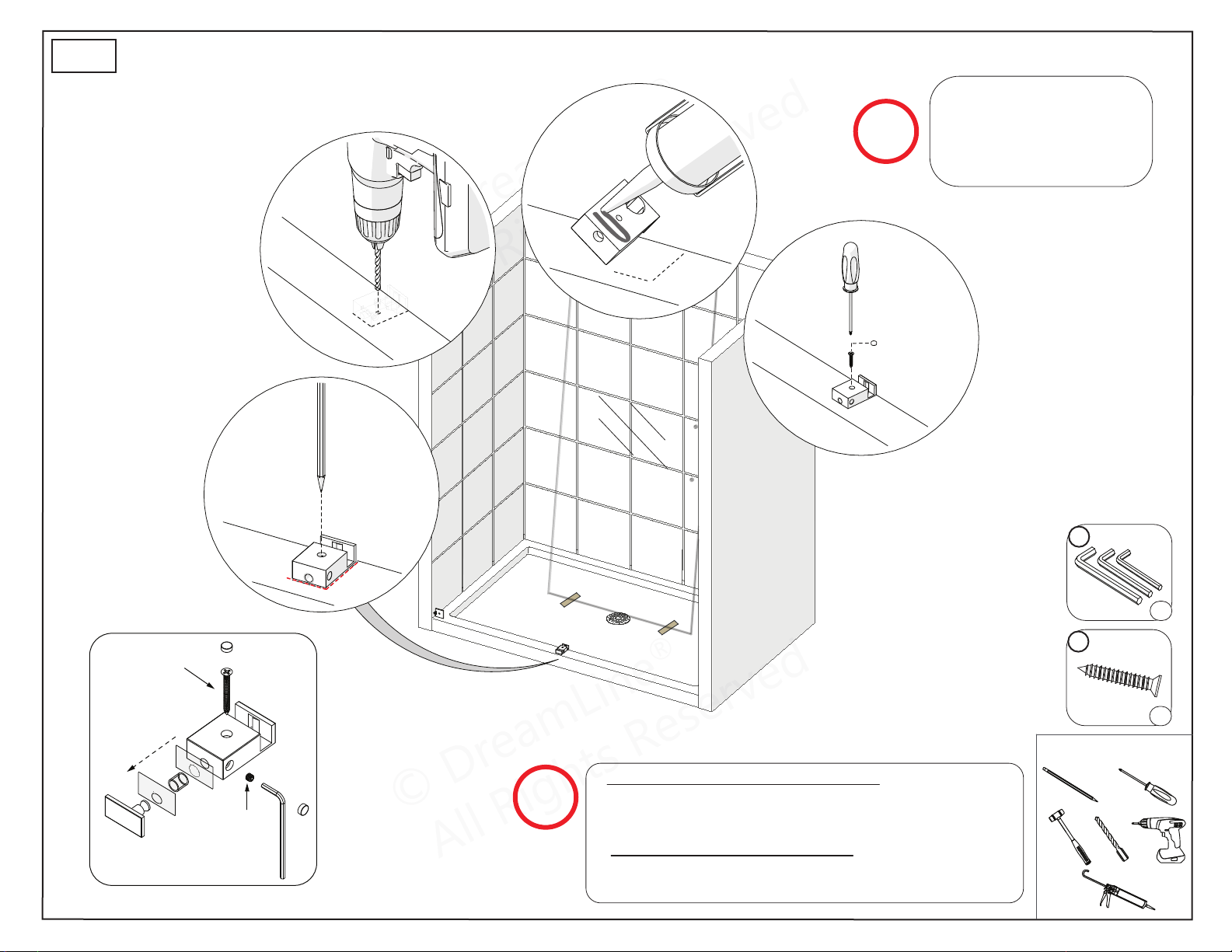
Fig 12
The adjustment set screws within the Guide Rail
Bracket (#08) must be aligned vertically
for easier access to adjust for level if necessary
after the glass is installed. Align the set screws
vertically and tighten.
DO NOT attach the handle to the Door Glass until instructed.
DO NOT attempt to lift the Door Glass with the handle as this may
result in damage to the glass and/or serious personal injury. Use a
professional grade glass suction cup and an assistant.
!
NOTE
72”
MODEL
ONLY
12
inside
inside
Before you install the Panel Glass (#02), attach the
top Roller Assemblies (#04) to the Door Glass
(#05) with the wheels facing outside of the shower.
Align the safety set screw towards the top for
easier access. Then, take the Door Glass (#05) into
the shower area and lean it against the wall with
the handle holes on the correct side. Always use
padding to protect the glass and shower surfaces.
TIP
safety set screw
(align to the top)
outside
*right-hand door
installation shown
10
18
x2
x2
04
x2
11
x1set
NOTE
Leave the corner protectors on the glass
until it is necessary to remove them
© DreamLine
®
All Rights Reserved
© DreamLine
®
All Rights Reserved
Tools Needed
Parts Needed
Guide Block Installation
ENIGMA-XO Shower and Tub Door Manual Ver 1 Rev 3 062019 24
© 2019 DreamLine® All Rights Reserved
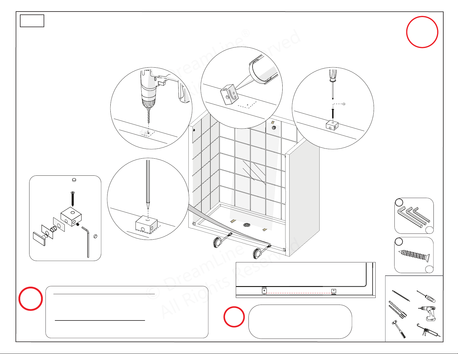
NOTE
◾For installation into an Acrylic Threshold:
drill a Ø1/8”(3mm) hole and use the ST4.2 x 40mm
Countersunk Screw (#17).
OR
◾For installation into a Tile Threshold:
drill a Ø3/16”(4mm) hole up to the stud
and use the ST4.2 x 40mm Countersunk Screw (#17).
Part #12 - Guide Block (with caps)
ST4.2×40
M5×10
13a
Contact the manufacturer
of the base, tub or threshold
material with any questions
regarding the drilling of
holes into their product.
NOTE
11
17
x1set
x1
use pencil
or a
center
punch to
mark the
hole.
1
2
3
4
Fig 13a
© DreamLine
®
All Rights Reserved
© DreamLine
®
All Rights Reserved
Tools Needed
Parts Needed
Guide Block Installation
ENIGMA-XO Shower and Tub Door Manual Ver 1 Rev 3 062019 25
© 2019 DreamLine® All Rights Reserved
NOTE
◾For installation into an Acrylic Threshold:
drill a Ø1/8”(3mm) hole and use the ST4.2 x 40mm
Countersunk Screw (#17).
OR
◾For installation into a Tile Threshold:
drill a Ø3/16”(4mm) hole up to the stud
and use the ST4.2 x 40mm Countersunk Screw (#17).
13b
1
2
3
4
72”
MODEL
ONLY
Contact the manufacturer of the
base, tub or threshold material with
any questions regarding the drilling
of holes into their product.
NOTE
11
17
x1set
x2
use pencil
or center-
punch to
mark the
hole.
Part #22 - Small Inline Panel
Glass Bottom Bracket
Fig 13b
Guide Block on Threshold Overview
© DreamLine
®
All Rights Reserved
© DreamLine
®
All Rights Reserved
Parts Needed
Guide Rail Bracket Adjustment
ENIGMA-XO Shower and Tub Door Manual Ver 1 Rev 3 062019 26
© 2019 DreamLine® All Rights Reserved
14
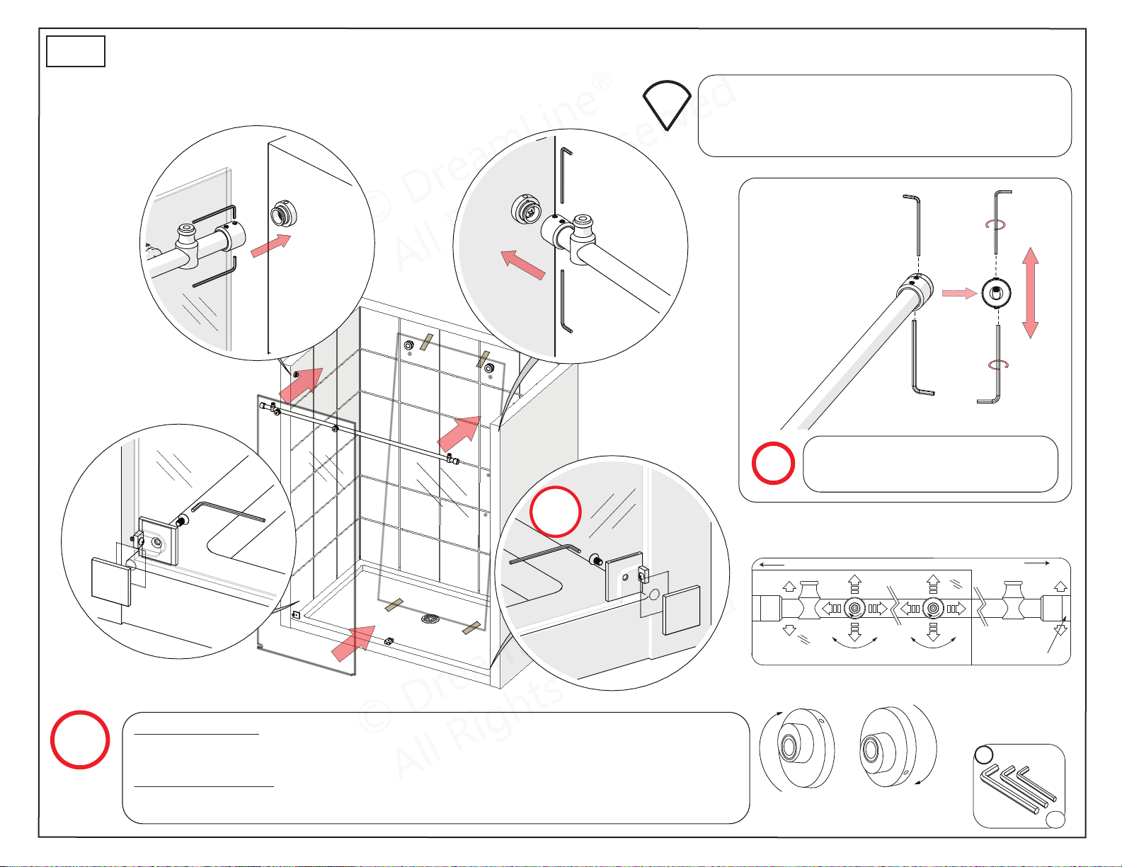
Adjust the installed Top Guide Rail (#03) to level as
necessary using the Guide Rail Brackets (#08) first
and then the Glass-to-Rail Brackets (#07).
Start adjustments from the door end.
TIP
To lower the rail:
Loosen the top set screw
and tighten the bottom
set screw.
To raise the rail:
Loosen the bottom set
screw and tighten the
top set screw.
Use the Guide Rail Bracket (#08) set
screws to adjust the Guide Rail (#03)
to level.
NOTE
11
x1set
72”
MODEL
ONLY
Fig 14
Panel end
Door end
Glass-to-Rail Bracket
Guide Rail Bracket
*Right-hand door installation shown
Lower guide rail Raise guide rail
Glass-to-Rail Bracket Adjustments
NOTE
For the 72” Model: Repeat this step for the Wall Bracket (#19) for the Small Inline Panel
Glass (#23) (Fig 14.4). Use the clear vinyl gasket between the glass and the metal parts to
avoid contact with the glass, then tighten the bolt using the supplied Allen Wrench (#11).
For Enclosure Model: Refer to Step 8 in the
Enigma-X/Enigma-XO Enclosure Return Panel
Manual to connect the shower assembly to the Return Panel using the Glass-to-Guide Rail
Connector (#28).
© DreamLine
®
All Rights Reserved
© DreamLine
®
All Rights Reserved
Tools Needed
Parts Needed
ENIGMA-XO Shower and Tub Door Manual Ver 1 Rev 3 062019 27
© 2019 DreamLine® All Rights Reserved
15
Fig 15a Fig 15b
72”
MODEL
ONLY
(X)
(X) + 3/8”
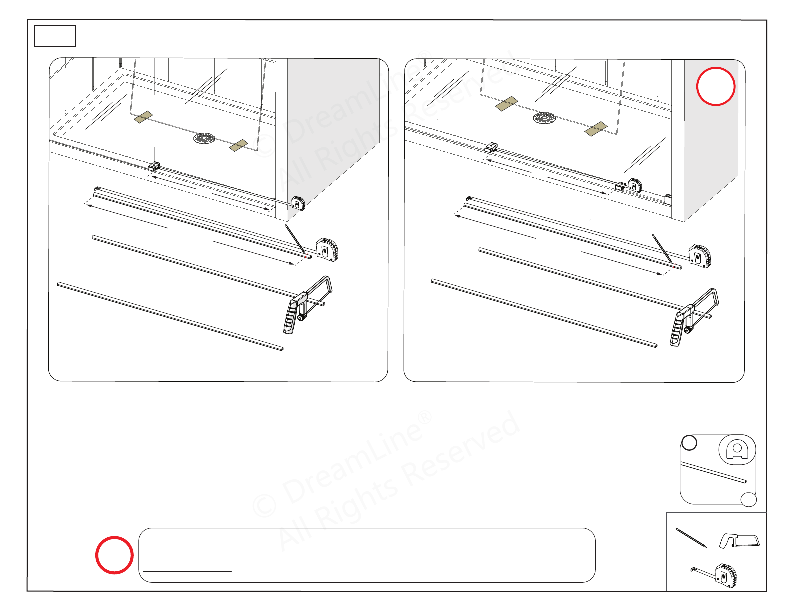
Measure the distance ‘X’ from the Guide Block (#12) to the
wall and add 3/8”.
(L)
(L) + 3/4”
Measure the distance ‘L’ between the guide blocks and add 3/4”.
NOTE
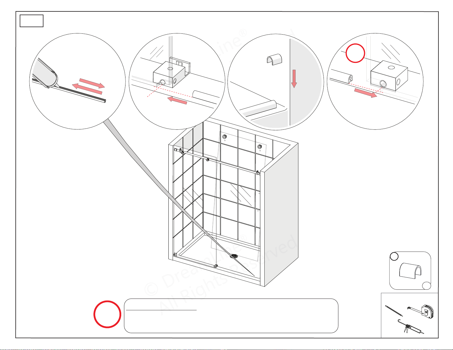
48”, 54“ or 60” Model Size: Cut the Dam Strip (#15) to the size of: (X) + 3/8”.
72” Model Size: Cut the Dam Strip (#15) to the size of: (L) + 3/4”.
15
x1
© DreamLine
®
All Rights Reserved
© DreamLine
®
All Rights Reserved
Tools Needed
Parts Needed
ENIGMA-XO Shower and Tub Door Manual Ver 1 Rev 3 062019 28
© 2019 DreamLine® All Rights Reserved
16
x1
only use cap when
installing up to a wall
(for 48” & 60” model)
72”
MODEL
ONLY
For the 72” Model: Insert the Dam Strip (#15) into the
Small Inline Panel Glass Bottom Bracket (#22).
(Fig 16.4*)
NOTE
Fig 16
1 2 3 4*
16
© DreamLine
®
All Rights Reserved
© DreamLine
®
All Rights Reserved
Tools Needed
Parts Needed
ENIGMA-XO Shower and Tub Door Manual Ver 1 Rev 3 062019 29
© 2019 DreamLine® All Rights Reserved
Fig 17
Fig 18
Guide Block (#12)
face plate
17
18
NOTE
TIP
Secure the Dam Strip (#15) to the threshold
with several pieces of painter’s tape until the
silicone fully cures.
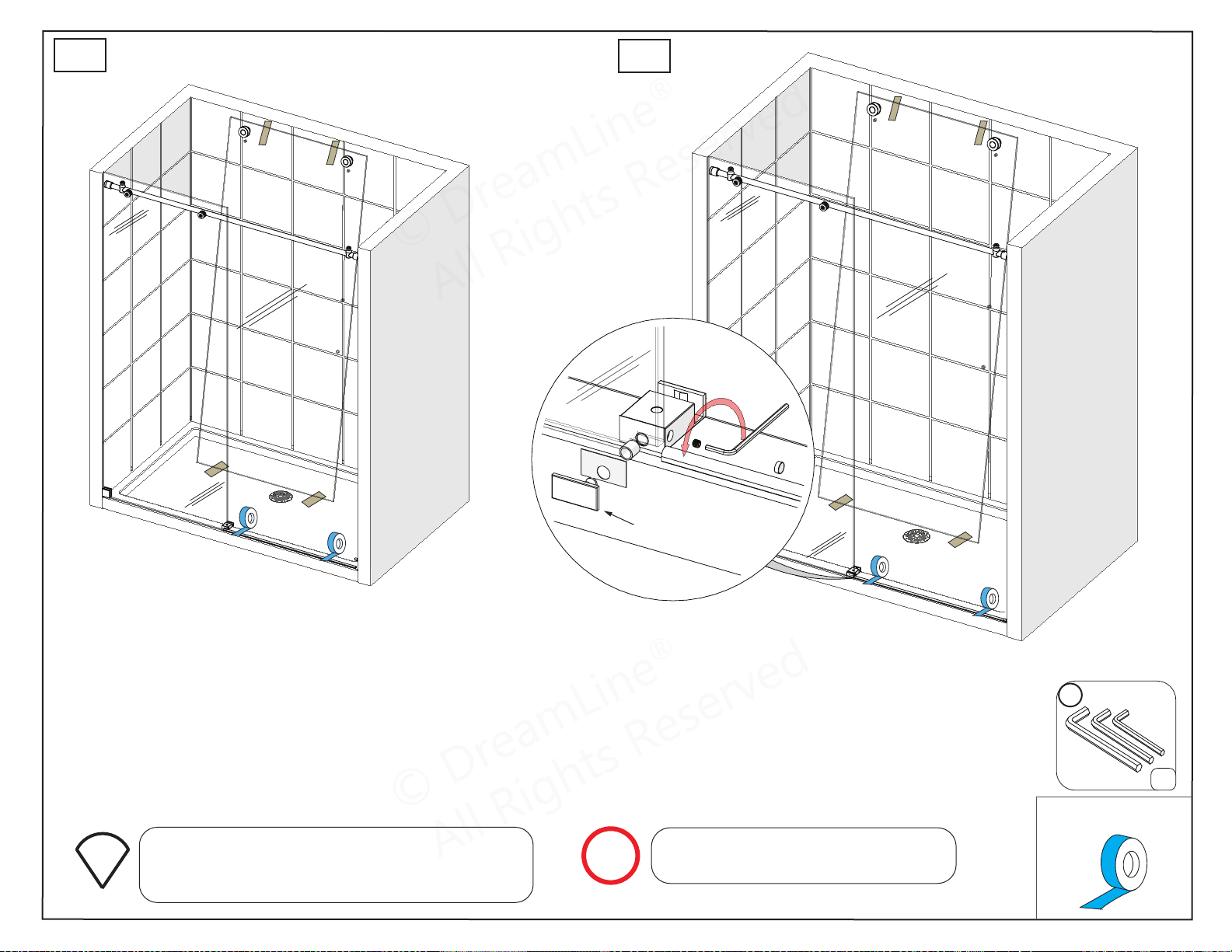
Attach the Guide Block face plate
to the installed Guide Block (#12).
11
x1set
© DreamLine
®
All Rights Reserved
© DreamLine
®
All Rights Reserved
Tools Needed
Parts Needed
ENIGMA-XO Shower and Tub Door Manual Ver 1 Rev 3 062019 30
© 2019 DreamLine® All Rights Reserved
Fig 19
Fig 20
72”
MODEL
ONLY
Guide Block (#12)
face plate
1 2 3
4
20
19
22
19
21
x1
x1
x1
23
x1
NOTE
Secure the Dam Strip (#15) to the
threshold with several pieces of painter’s
tape until the silicone fully cures.
outside
© DreamLine
®
All Rights Reserved
© DreamLine
®
All Rights Reserved
Parts Needed
Upper Roller Assembly Installation
ENIGMA-XO Shower and Tub Door Manual Ver 1 Rev 3 062019 31
© 2019 DreamLine® All Rights Reserved
Fig 21
Roller Assembly Wheel Adjustment
Raise glassLower glass
**add threadlock to
the safety set screw
and wheel bolt
11
26
x1set
x1
!
NOTE
inside
1
2
3
TIP
TIP
Panel
Glass
Door
Glass
inside
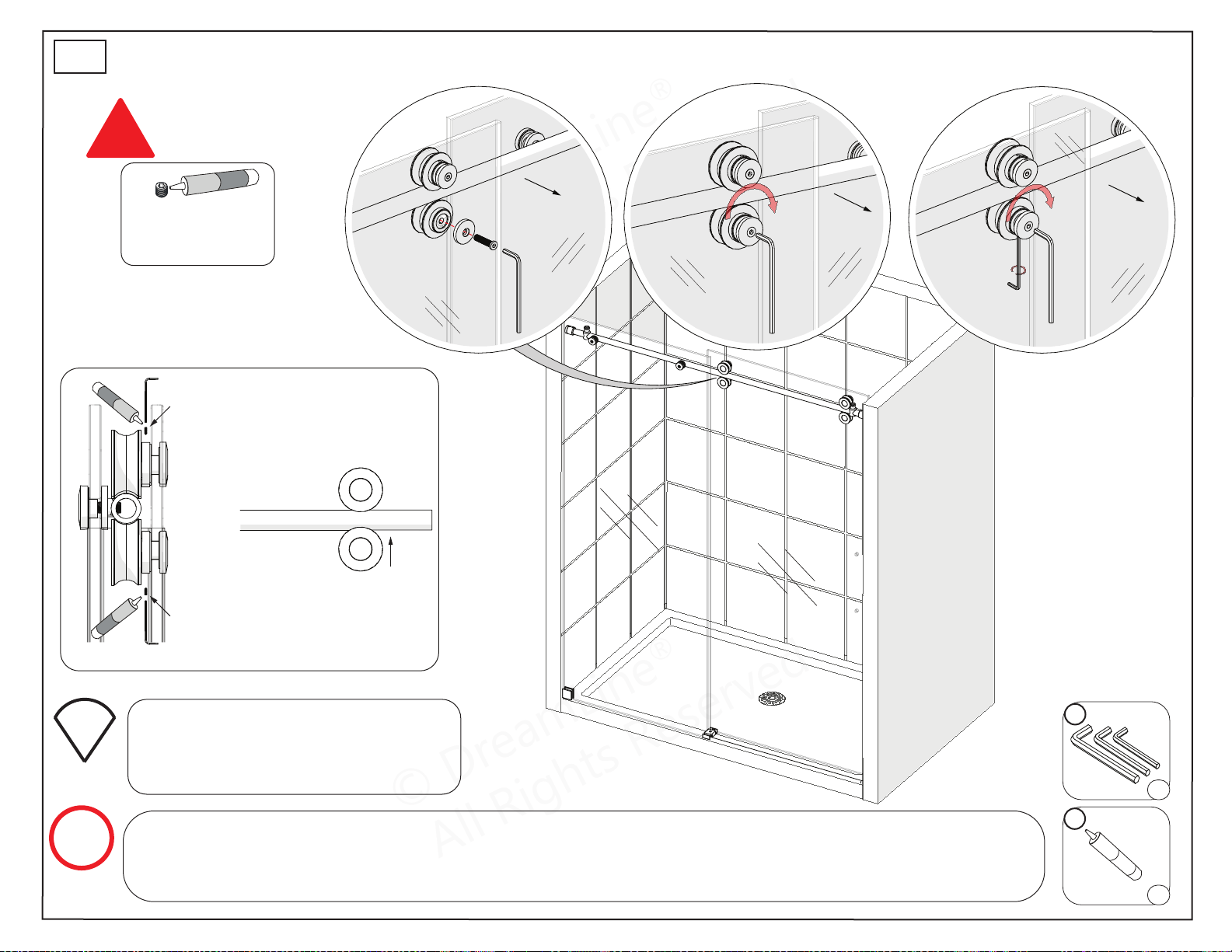
Mark the location of the high spot on
the outer surface of the adjustment
disk with a felt tip pen to make
adjustment easier to see.
Use a 3/16” shim beneath the Door Glass (#05)
when adjusting the level of the door so that the
glass does not make contact with the guide
block.
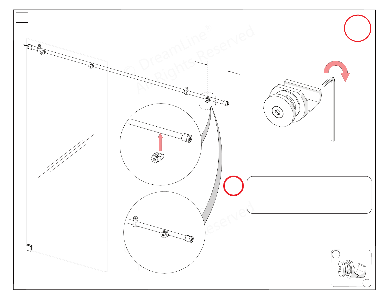
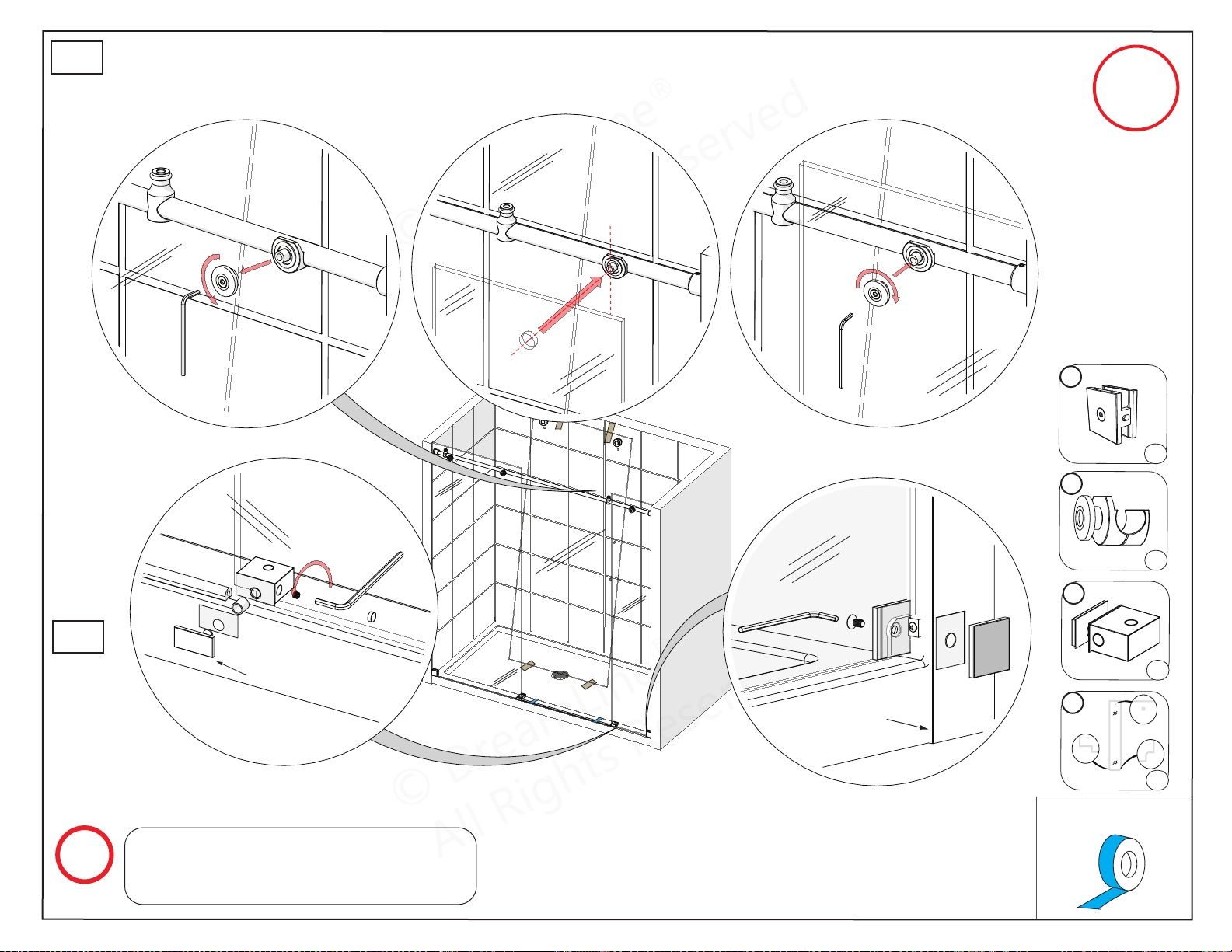
The adjustment disks in the wheels are the same as the disks in the Glass-to-Rail Brackets and can be
rotated to adjust the Door Glass (#05) to create a seal with the wall. The Safety Set Screw on both Roller
Assembly Wheels MUST be re-tightened after installation to prevent the wheel bolt from becoming
loose. Apply Thread Lock Adhesive (#26) during installation. See detailed description on page 34.
21
inside
safety set screw
(must be on top)
Adjustment Disk
Neutral Position
© DreamLine
®
All Rights Reserved
© DreamLine
®
All Rights Reserved
Parts Needed
Lower Roller Assembly Installation
ENIGMA-XO Shower and Tub Door Manual Ver 1 Rev 3 062019 32
© 2019 DreamLine® All Rights Reserved
11
26
x1set
x1
**add threadlock to
the safety set screw
and wheel bolt
!
1 2 3
NOTE
TIP
Mark the location of the high spot on
the outer surface of the adjustment
disk with a felt tip pen to make
adjustment easier to see.
The adjustment disks in the wheels are the same as the disks in the Glass-to-Rail Brackets and can be rotated to adjust
the Door Glass (#05) to create a seal with the wall. The Safety Set Screw on both Roller Assembly Wheels MUST be
re-tightened after installation to prevent the wheel bolt from becoming loose. Apply Thread Lock Adhesive (#26)
during installation. See detailed description on page 33.
22
inside
inside
inside
safety set screw
(align to the top)
safety set screw
(align to the bottom)
Top Guide Rail
side view
front view
© DreamLine
®
All Rights Reserved
© DreamLine
®
All Rights Reserved
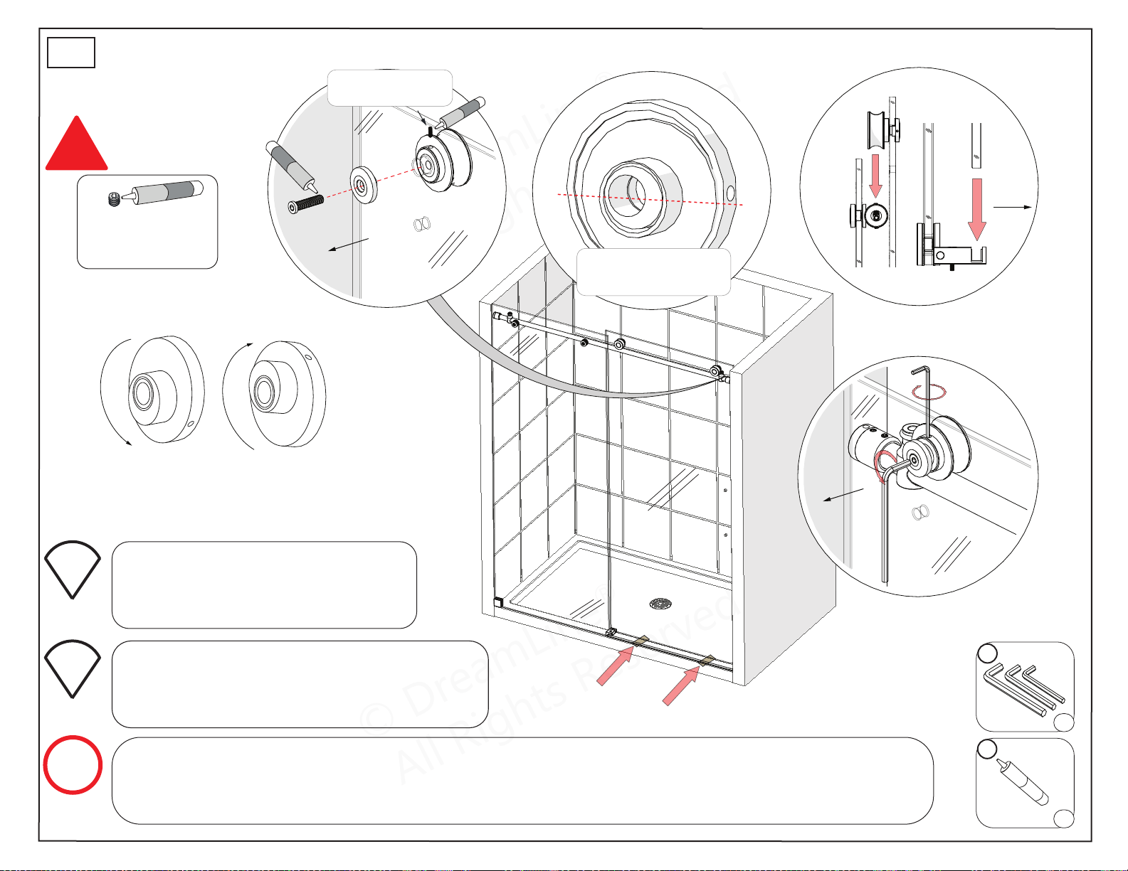
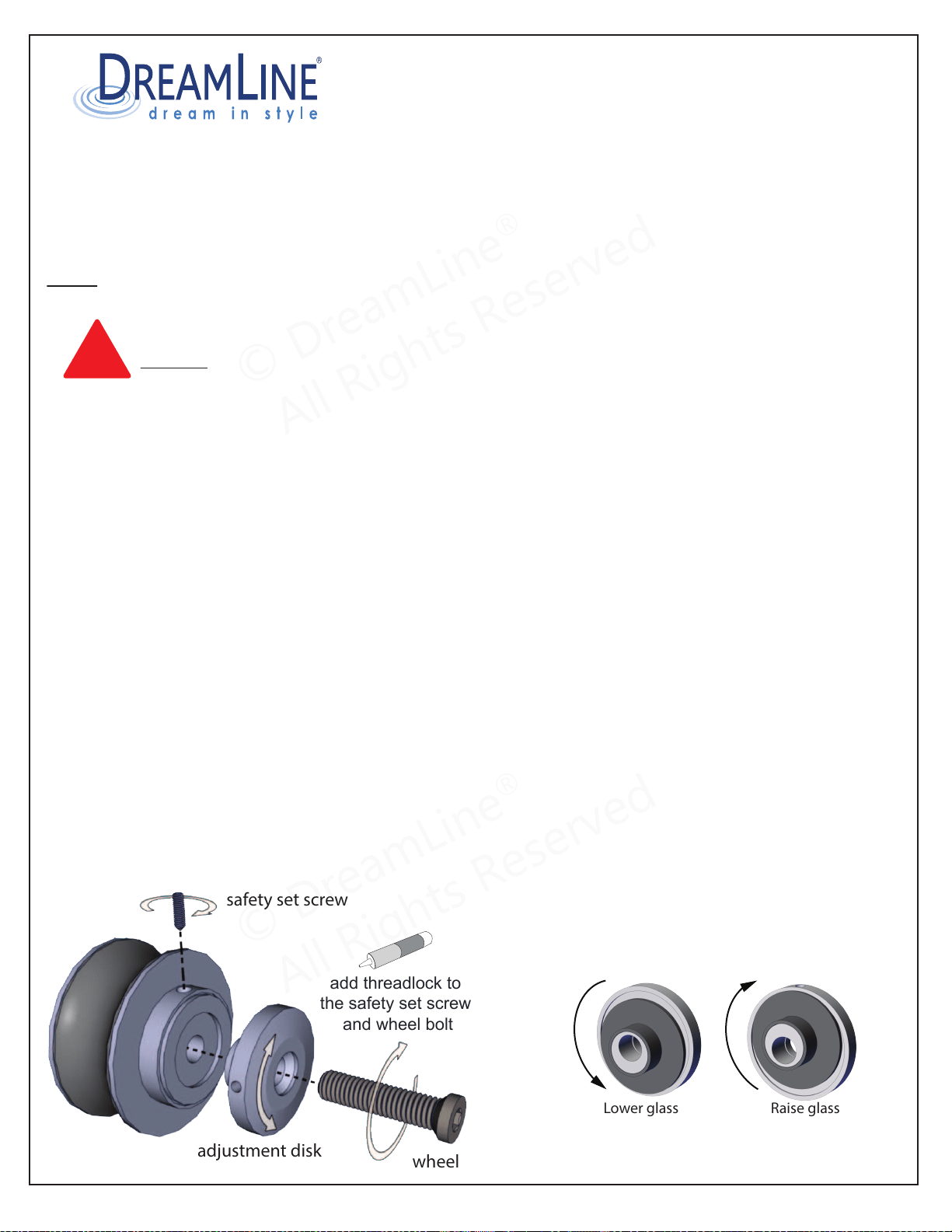
To create a good seal with the wall and to achieve minimal clearance beneath the door glass without making
contact with the bottom guide block or threshold.
Have at least two 3/16” shims or wedge shims (to maintain space beneath the door glass) and an assistant
available to help with this procedure.
Adjust only one wheel at a time. You may need to perform these steps more than once to get the desired results.
NOTE: Be sure to install the Bulb Vinyl Seal onto the edge of the door glass to protect the edge from
contact with the wall during installation or adjustment.
CAUTION: The door glass is heavy and may require two people to safely accomplish these steps.
DO NOT adjust the Roller Assemblies without first securing the door glass with shims, an assistant or
both.
1. First, loosen and lower either the Roller Guards (Enigma-X) or Bottom Rollers (Enigma/Enigma-XO) to allow
enough room to adjust the upper rollers.
2. Loosen the safety set screw on the roller (remove and apply a drop of thread lock if not done already)
3. Loosen the wheel bolt just enough so that you can rotate the adjustment disk. (remove and apply a drop of
thread lock if not done already)
4. Rotate the adjustment disk to raise or lower the door slightly with help from an assistant. You can use a small
tool (like an allen wrench) to aid in turning this disk by inserting it into the small hole on the edge of the
adjustment disk.
5. While holding the adjustment disk in place, retighten the wheel bolt. Use a shim or have an assistant hold the
door glass in place while you retighten the wheel bolt.
6. Once satisfied with the adjustment, it is very important to re-tighten the safety set screw to secure the
wheel bolt in place.
7. For the Enigma-X: Reposition the roller guards approximately 1/16” beneath the guide rail and retighten.
For the Enigma and Enigma-XO: adjust the lower rollers to make contact with the guide rail using the same
methods as described in the steps above.
Roller Assembly Adjustment Procedure for:
Enigma, Enigma-X, Enigma-XO
The provided Thread Lock will remain workable
for approximatley 10-15 minutes before drying.
Roller wheel adjustment disks
add threadlock to
the safety set screw
and wheel bolt
safety set screw
adjustment disk
wheel bolt
!
Raise glassLower glass
33ENIGMA-XO Shower and Tub Door Manual Ver 1 Rev 3 03/2019
©2019 DreamLine
®
All Rights Reserved
© DreamLine
®
All Rights Reserved
© DreamLine
®
All Rights Reserved
Tools Needed
Parts Needed
Vinyl Seals & Handle Installation
ENIGMA-XO Shower and Tub Door Manual Ver 1 Rev 3 062019 34
© 2019 DreamLine® All Rights Reserved
NOTE
TIP
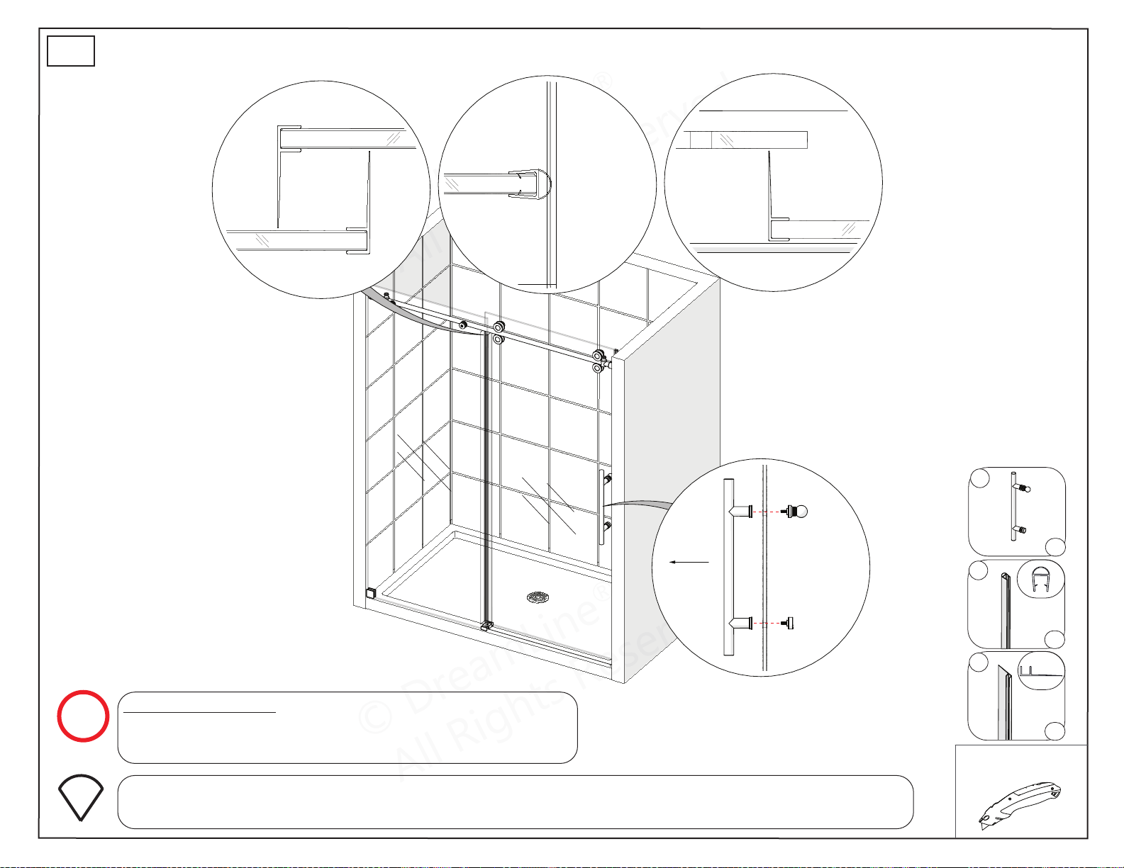
For the 72” Model: Attach the Vertical Vinyl Seal (#14)
to the edge of the Small Inline Panel Glass (#23). The
Bulb Vinyl Seal (#13) is not necessary with the 72” model.
Use a razor knife to trim the Vertical Vinyl Seal (#14) at the top to avoid interfering with the
Roller Guards (#29) and at the bottom where the door meets the SafeStop™ Bumper (#30). (Fig 23)
Fig 23
*Right-hand door installation shown.
wall
door glass
small inline
panel
door glass
door glass
panel glass
outside
06
13
14
x1
x1
x2
23
© DreamLine
®
All Rights Reserved
© DreamLine
®
All Rights Reserved
Parts Needed
Door Stopper Installation
ENIGMA-XO Shower and Tub Door Manual Ver 1 Rev 3 062019 35
© 2019 DreamLine® All Rights Reserved
24
11
26
01
x2
x1set
x1
2”
minimum
small inline
panel glass
1 2 3
4
6*
5
!
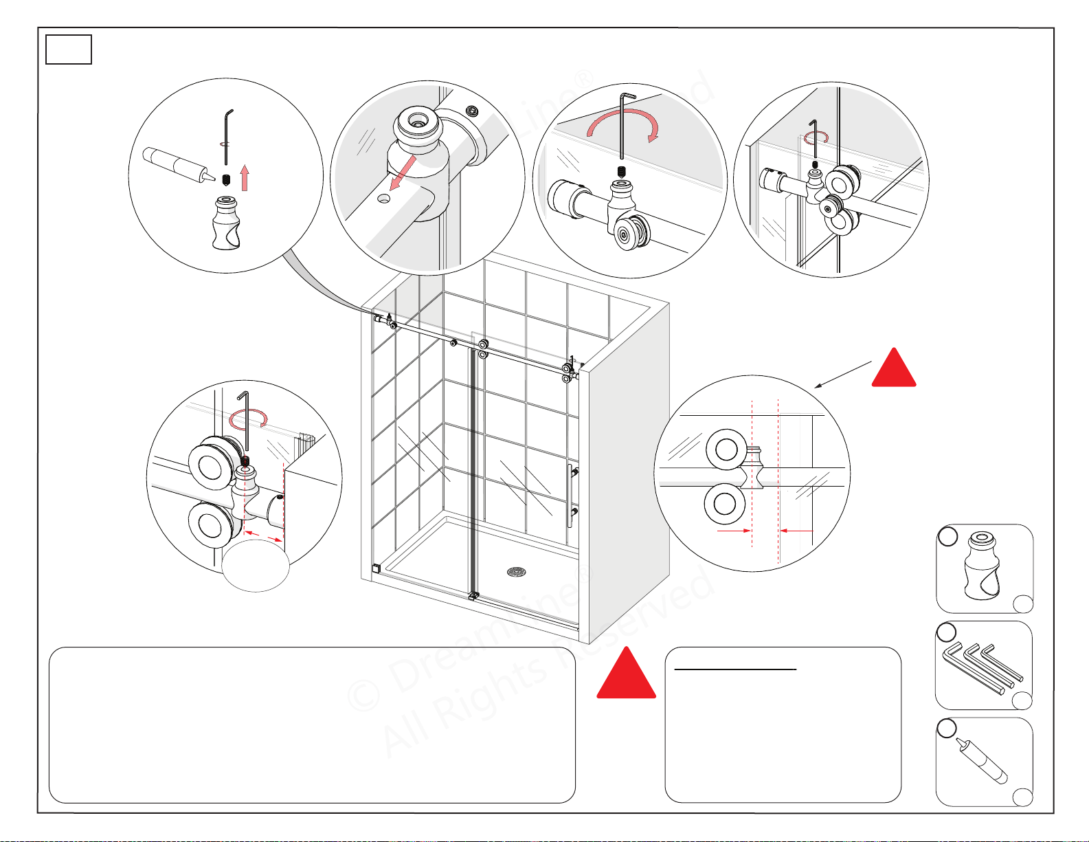
Position the door-side
Stopper (#01)
to allow enough clearance
for the handle.
door side
3”
(+/- 1/8”)
approximately
!
Door Stopper Installation:
1. Remove the set screw
2. Slide the Door Stopper (#01) onto the Top Guide Rail (#03)
3. Align with stopper hole in the guide rail (inline panel side only) (Fig 24.2)
4. Apply Thread Lock Adhesive (#26) to the set screw threads
5. Tighten screw into the stopper hole (inline panel side only)
6. Correctly position the door side stopper, use Thread Lock Adhesive (#26)
and tighten the set screw. (Fig 24.5)
*For 72” Model: Position the
door-side Stopper (#01) at
least 2” away from the small
inline panel glass so that the
handle cannot make contact
with the glass when the door
is in the closed position.
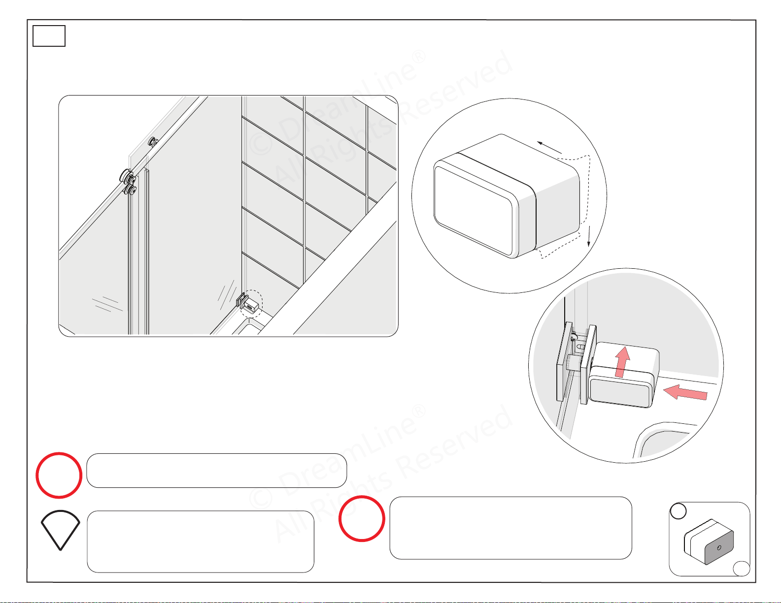
© DreamLine
®
All Rights Reserved
© DreamLine
®
All Rights Reserved
Parts Needed
SafeStop™ Bumper Installation - Option 1
ENIGMA-XO Shower and Tub Door Manual Ver 1 Rev 3 062019 36
© 2019 DreamLine® All Rights Reserved
25
wall
inside
REMOVE 3M™ TAPE
30
x1
NOTE
NOTE
The surfaces need to be clean and free of
construction debris before installing the
SafeStop™ Bumper (#30). Wipe the area
with an alcohol swab before installation.
The SafeStop™ Bumper (#30) is reversible for
left or right wall installation.
door glass
inline panel
wall
inside
Fig 25
*Right-hand door installation shown.
TIP
Install the SafeStop™ Bumper (#30)
using the 3M™ tape.
Screwing the SafeStop™ Bumper to the
wall is optional (see step 26*).
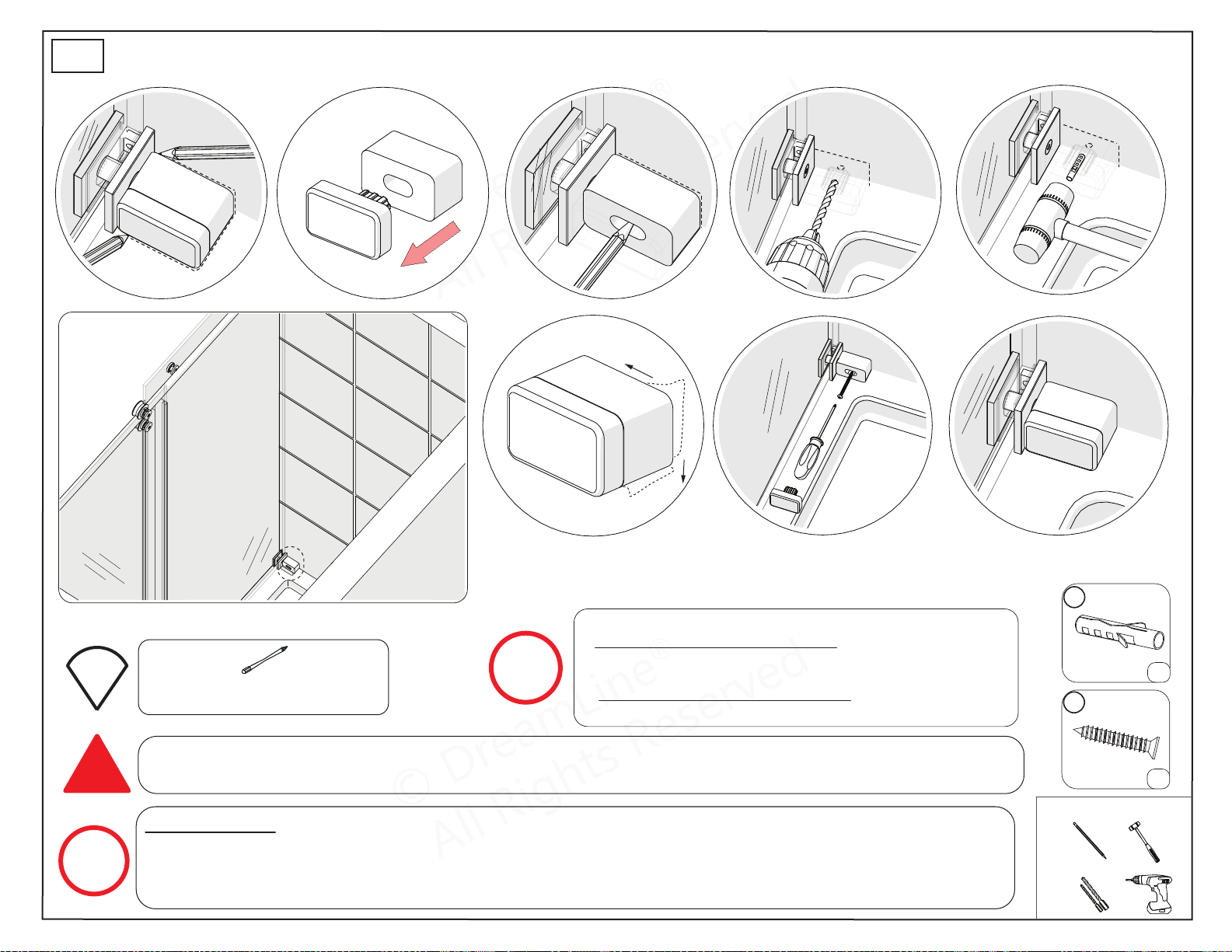
© DreamLine
®
All Rights Reserved
© DreamLine
®
All Rights Reserved
Tools Needed
Parts Needed
SafeStop™ Bumper Screw Installation - Option 2
ENIGMA-XO Shower and Tub Door Manual Ver 1 Rev 3 062019 37
© 2019 DreamLine® All Rights Reserved
Fig 26
REMOVE 3M™ TAPE
1 2 3 4* 5*
876
26
door glass
inline panel
wall
inside
*Right-hand door installation shown.
09b
17
x1
x1
Extender driver bit recommended
for screw installation.
!
NOTE
TIP
Use caution to not damage/crack the wall/tile and to avoid any plumbing behind the wall when using the
screw method .
For 72” Model: This will be the side of the opening with the large stationary panel. Mark the position of
the hole onto the wall. Drill the correct hole diameter (see Note above). Remove the 3M™ Tape and
position the SafeStop™ Bumper (#30) onto the threshold against the Wall Bracket (#19) and attach
using the ST4.2 x 40 Countersunk Screw (#17). (Fig 26)
NOTE
For installing the SafeStop™ Bumper::
◾If a stud is present behind the wall:
drill a Ø3/16”(4mm) hole up to the stud.
OR
◾If no stud is present behind the wall:
drill a Ø5/16”(10mm) hole and install the Wall Anchor (#09b).
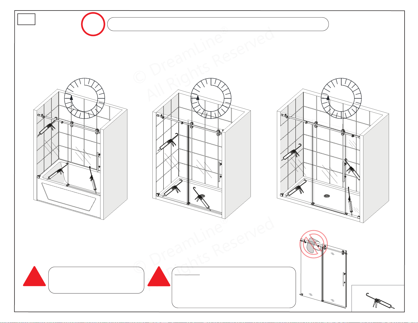
© DreamLine
®
All Rights Reserved
© DreamLine
®
All Rights Reserved
Tools Needed
ENIGMA-XO Shower and Tub Door Manual Ver 1 Rev 3 062019 38
© 2019 DreamLine® All Rights Reserved
NOTE
The surfaces need to be clean and free of debris before applying silicone.
27
!
!
DO NOT hang or drape a towel or wash
cloth over the Enigma Top Guide Rail as
this may cause the Roller Assembly wheels
to get stuck and possibly cause serious
damage or injury.
Allow 24 hours for the silicone
to cure before using the
shower.
24
Hours
24
Hours
24
Hours
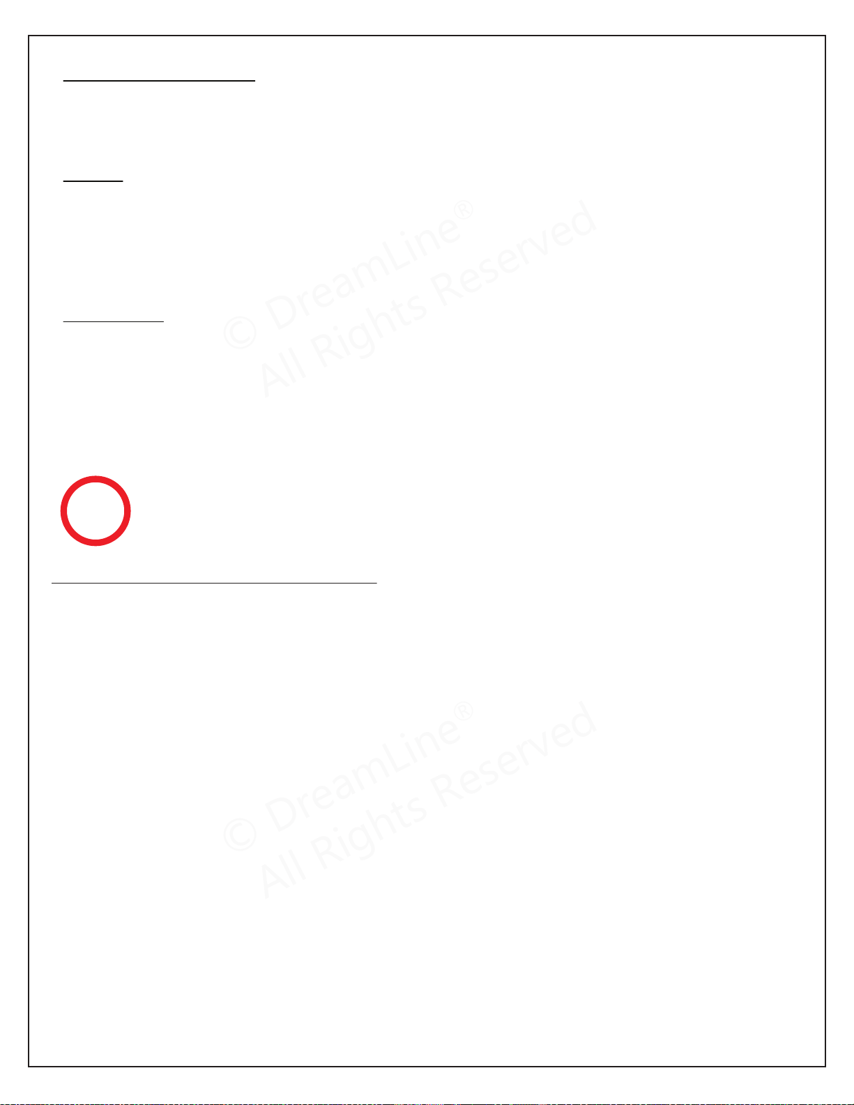
© DreamLine
®
All Rights Reserved
© DreamLine
®
All Rights Reserved
Product Maintenance
ENIGMA-XO Maintenance Checklist
◻ Guide Rail level and tight
◻ Guide Rail Brackets tight to the wall
◻ All set screws are tight and secured with threadlock
◻ Panel Glass secure
◻ Panel Glass-to-Rail Brackets tight
◻ Guide Block square to the threshold and glass
◻ Proper clearance beneath the Door Glass between the threshold and within the Guide Block
◻ Door Glass adjusted so that the Bulb Vinyl Seal makes even contact with the wall
◻ Roller Wheel Assemblies tight
◻ Roller Wheel Assembly bolts tight
◻ Roller Wheel Assembly safety set screws tight, accessible and set with threadlock
◻ Door Stoppers tight and positioned correctly
◻ Panel-side Door Stopper installed into the pre-drilled hole in the Upper Guide Rail
◻ Adequate Handle clearance when the door is fully open
◻ Door-side Door Stopper positioned at approximately 3” (+/- 1/8”) (as measured from the
wall to the center of the stopper)
◻ Check that the Stopper stops the door and the Bulb Vinyl Seal makes contact with the wall
◻ SafeStop™ Bumper secured to the wall
◻ Bottom Roller Wheel Assemblies should make contact with the Upper Guide Rail
◻ Remove Vertical Vinyl Seals to inspect the edges of the door glass for concealed damage
◻ Damaged Glass must be replaced!
◻ Replace damaged or missing vinyl seals
◻ Inspect and replace silicone as necessary to prevent water leakage
To maximize the life of your door, it is important to regularly inspect
the glass and other hardware for misalignment, proper attachment,
and/or damage. Contact DreamLine
®
with any questions or concerns.
NOTE
BASES and BACKWALLS: To ensure long lasting life for your acrylic back walls: wipe them off
after each use with a soft cloth. To clean the acrylic back walls use non-abrasive sprays or cream
based cleaners. Avoid the use of aerosol spray cleaners. Never use abrasive cleansers, metal
brushes or scrapers that could permanently scratch or dull the surface.
GLASS: To ensure long lasting life for your glass shower products: wipe them off after each use
with a soft cloth. Rinse and wipe off the glass using either a soft cloth or a squeegee to prevent
soap buildup and water spots (Hard water can etch the surface of the glass over time if left to dry).
To prevent scratching the surface: never use abrasive cleaners or cleaning products that contain
scouring agents. Never use bristle brushes or abrasive sponges that may scratch the surface of the
glass.
HARDWARE: To ensure a long lasting finish: wipe off all metal parts after each use with a soft
cloth. Do not use abrasive cleaners or cleaning products containing ammonia, bleach or acid. If
accidentally used, rinse the surface as soon as possible to prevent damage to the finish (peeling or
corrosion). After cleaning the polished finishes, rinse thoroughly and wipe dry with a soft clean-
cloth.
Clean stainless steel surfaces at least once a week. When applying stainless steel cleaner or polish
to stainless steel hardware, work with the grain (not across the grain). Never use an abrasive
sponge or cloth, steel wool or wired brush as these may permanently scratch the surfaces.
ENIGMA-XO Shower and Tub Door Manual Ver 1 Rev 3 062019 39
©2019 DreamLine
®
All Rights Reserved
© DreamLine
®
All Rights Reserved
© DreamLine
®
All Rights Reserved
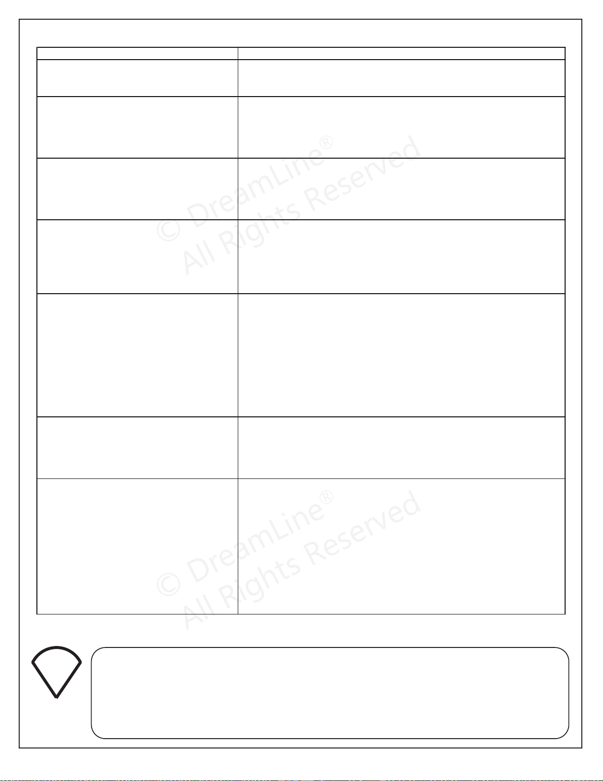
Troubleshooting
Prior to contacting DreamLine® Customer Service, please have the following information
readily available:
- Purchase Order Information
- Name, PO Number, Dealer/Vendor Name, etc.
- SKU/Model Number (see Pages 41-44)
- Factory Part Information (see Pages 41-44)
TIP
Problem/Symptom
Suggested Solution
Missing Parts
•Check all shipping/packaging material for missing parts/components.
•If not found, contact DreamLine® Customer Support [1-866-731-2244] to order
factory part replacement.
Top Guide Rail (#03) was cut too short or was cut
from wrong end during installation.
•The Top Guide Rail (#03) is pre-cut for the model size, and will be shorter than the
model width to allow for the Guide Rail Brackets (#08).
•If the Top Guide Rail (#03) is cut too short or cut from the wrong end, contact
DreamLine® Customer Support [1-866-731-2244] to order factory part replacement.
Water Leakage
•Confirm the Dam Strip (#15), Bulb Vinyl Strip (#13), and the Vertical Vinyl Strips
(#14) are installed correctly. [see Page 34]
•Confirm that the entire unit has been properly sealed with silicone caulk; allow at least
24 hours to allow the silicone to cure and set before using the shower unit.
•Direct the shower head/water flow away from the area.
The door rolls open or closed
•Check the Top Guide Rail (#03) for level. Adjust the Guide Rail Brackets (#08) if
necessary. [see Step 14]
•Adjust the Roller Wheel Assemblies (#04) on the door, if needed, to allow the door
to seal evenly against the wall.
•To influence the Top Guide Rail (#03) slightly, the innermost Glass-to-Rail Brackets
(#07) can be adjusted.
The door does not track smoothly
•Confirm the Guide Block (#12) is square to the Panel Glass (#02) and threshold.
[see Steps 13a-136b]
•Confirm the Door Glass (#05) is not making contact with the bottom of the Guide
Block (#12).
•If the Door Glass (#05) needs to be raised, adjust the Upper Roller Wheel
Assemblies (#04) to raise it. [see Pages 31-32]
•Be sure that there is nothing on the Top Guide Rail (#03) that could block the Roller
Wheel Assemblies (#04).
•Check the Bottom Wheel Assemblies (#04) are making contact with the Top Guide
Rail (#03). [see Page 33]
Door travels too far in either direction
•Confirm both Door Stoppers (#01) are correctly installed and secured with the
Threadlock Adhesive (#26).
•Check that the Door Stopper (#01) on the Panel Glass (#02) side is tightly installed
into the hole on the Top Guide Rail (#03). The Door Stoppers (#01) should stop t
he
door glass, not the wall. [see Page 35]
Mishandled glass
•Always take precautions when handling tempered glass.
•A glass suction cup and an assistant are helpful when carrying large, heavy lites of
glass.
•Never allow tempered glass (especially the edges) to com
e in contact with any hard
surface, which can cause chipping, splintering or complete glass failure.
•Any damaged glass should be immediately replaced.
•Do not use a shower with damaged glass.
•Leave plastic corner protectors on the glass until ready to install
.
•Always protect the glass once removed from the box by padding the top and bottom
of the glass with cardboard, styrofoam or other soft material until ready to install.
DRAFT_MIRAGE-X Shower and Tub Door Manual Ver 1 Rev 6 01/2019 40
©2019 DreamLine
®
All Rights Reserved
© DreamLine
®
All Rights Reserved
© DreamLine
®
All Rights Reserved
Factory Parts Information
Contact [email protected] for Part replacement, installation assistance or additional information.
Complete Warranty information is available on DreamLine.com.
BOLD digit indicates finish color:
1 or 8 = Polished SS
4 or 5 or 7 = Brushed SS
6 = Oil Rubbed Bronze
9 = Satin Black
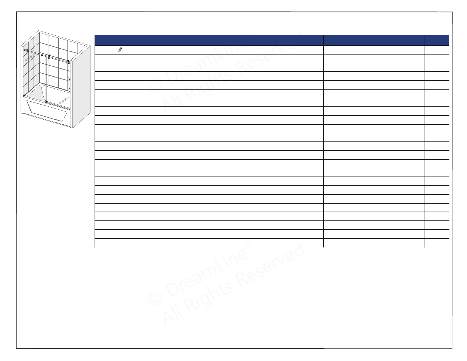
FACTORY PARTS INFORMATION
ITEM
#
FACTORY PART NUMBER ITEM DESCRIPTION QTY
01 07021036 /07025036 / 07026036 / 07029036 Door Stopper 2pcs
02 010112005 Inline Panel Glass 1pc
03 07121044 / 07125044 / 07126044 / 07129044 Top Guide Rail 1pc
04 07351006 / 07355006 / 07356006 / 07359006 Roller Assembly 4pcs
05 010114001 Door Glass 1pc
06 07221003 / 07225003 / 07226003 / 07229003 Handle 1pc
07 07021104 / 07025104 / 07026104 / 07029104 Glass-to-Rail Bracket 2pcs
08 07021097 / 07025097 / 07026097 / 07029097 Guide Rail Bracket 2pcs
09a 07550044 Wall Anchor 3/8” (10mm) 2pcs
09b 07550045 Wall Anchor 5/16” (8mm) 3pcs
10 090112 ST6x65 Large Truss Head Screw 2pcs
11 098003 / 098004 / 098005 Allen Wrench (3mm, 4mm, 5mm) 1set
12 07021138 / 07024138 / 07026138 / 07029138 Guide Block (with caps) 1pc
13 063007100-1565 Bulb Vinyl Seal 1pc
14 063027100-1436 & 063027100-1445 Vertical Vinyl Seal 2pcs
15 04100011-0813 / 04100041-0813 / 04100061-0813 / 04100091-0813 Dam Strip 1pc
16 07551068 / 07554068 / 07556068 / 07559068 Dam Strip Cap 1pc
17 092108 ST4.2x40 Countersunk Screw 2pcs
18 090113 ST4.2x55 Truss Head Screw 1pcs
19 07021004 / 07024004 / 07026004 / 07029004 Wall Bracket 1pc
26 160012 Thread Lock Adhesive 1pc
30 07021153 / 07024153 / 07026153 / 07029153 SafeStop™ Bumper 1pc
60x62 ENIGMA-XO Tub {SHDR-61606220-##}
SHDR-61606220-##
ENIGMA-XO Shower and Tub Door Manual Ver 1 Rev 3 062019 41
© 2019 DreamLine® All Rights Reserved
© DreamLine
®
All Rights Reserved
© DreamLine
®
All Rights Reserved
Factory Parts Information
Contact [email protected] for Part replacement, installation assistance or additional information.
Complete Warranty information is available on DreamLine.com.
BOLD digit indicates finish color:
1 or 8 = Polished SS
4 or 5 or 7 = Brushed SS
6 = Oil Rubbed Bronze
9 = Satin Black
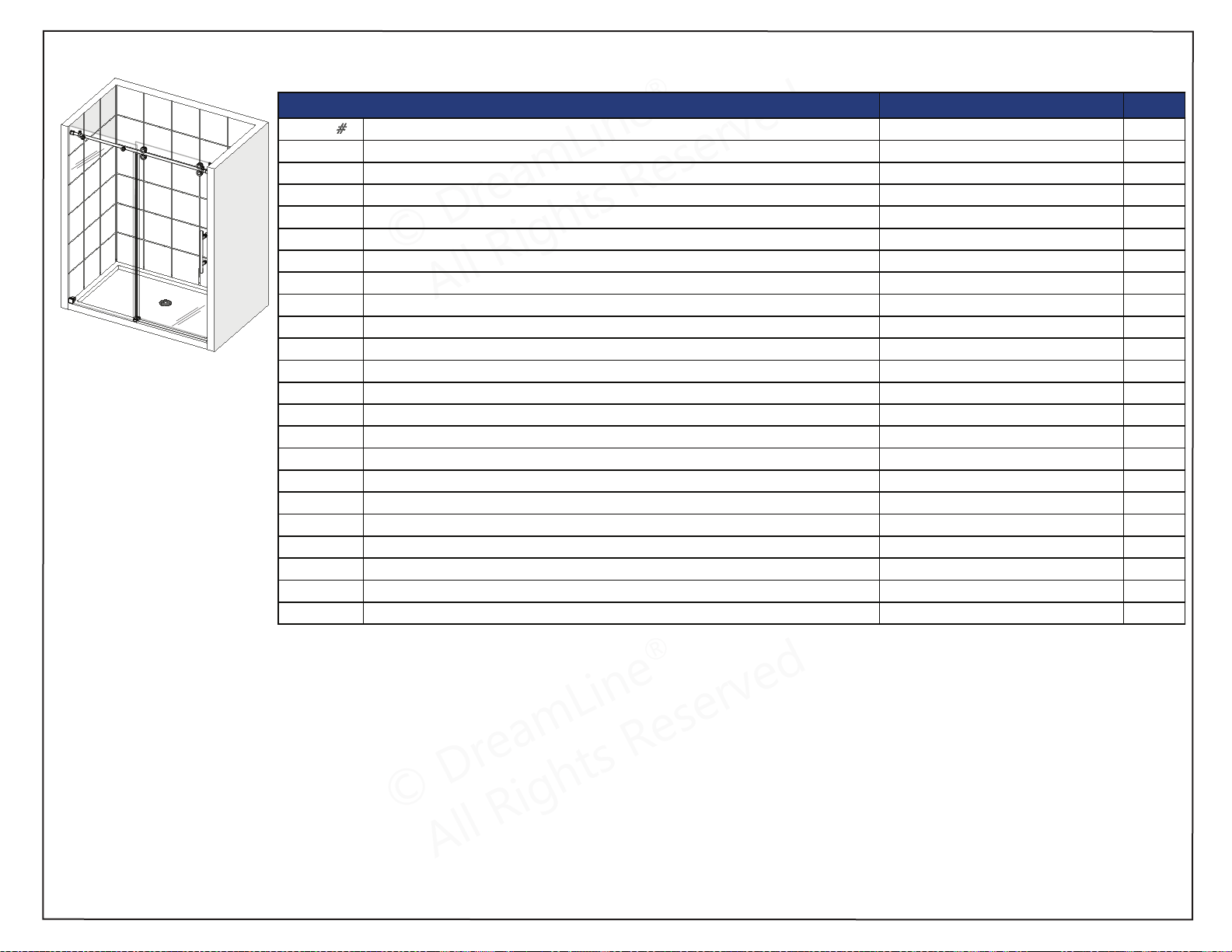
FACTORY PARTS INFORMATION
ITEM
#
FACTORY PART NUMBER ITEM DESCRIPTION QTY
01
07021036 /07025036 / 07026036 / 07029036
Door Stopper
2pcs
02 010112001 Panel Glass
1pc
03
07121043 / 07125043 / 07126043 / 07129043
Top Guide Rail
1pc
04
07351006 / 07355006 / 07356006 / 07359006
Roller Assembly
4pcs
05
010114003
Door Glass
1pc
06
07221003 / 07225003 / 07226003 / 07229003
Handle
1pc
07
07021104 / 07025104 / 07026104 / 07029104
Glass-to-Rail Bracket
2pcs
08
07021097 / 07025097 / 07026097 / 07029097
Guide Rail Bracket
2pcs
09a
07550044
Wall Anchor 3/8” (10mm)
2pcs
09b
07550045
Wall Anchor 5/16” (8mm)
3pcs
10
090112
ST6x65 Large Truss Head Screw
2pcs
11
098003 / 098004 / 098005
Allen Wrench (3mm, 4mm, 5mm)
1set
12
07021138 / 07024138 / 07026138 / 07029138
Guide Block (with caps)
1pc
13
063007100-1921
Bulb Vinyl Seal
1pc
14
063027100-1800 & 063027100-1791
Vertical Vinyl Seal
2pcs
15
04100011-0660 / 04100041-0660 / 04100061-0660 / 04100091-0660
Dam Strip
1pc
16
07551068 / 07554068 / 07556068 / 07559068
Dam Strip Cap
1pc
17
092108
ST4.2x40 Countersunk Screw
2pcs
18
090113
ST4.2x55 Truss Head Screw
1pcs
19
07021004 / 07024004 / 07026004 / 07029004
Wall Bracket
1pc
26
160012
Thread Lock Adhesive
1pc
30
07021153 / 07024153 / 07026153 / 07029153
SafeStop™ Bumper
1pc
48x76 ENIGMA-XO Shower {SHDR-61487620-##}
SHDR-61487620-##
ENIGMA-XO Shower and Tub Door Manual Ver 1 Rev 3 062019 42
© 2019 DreamLine® All Rights Reserved
© DreamLine
®
All Rights Reserved
© DreamLine
®
All Rights Reserved
Factory Parts Information
Contact [email protected] for Part replacement, installation assistance or additional information.
Complete Warranty information is available on DreamLine.com.
BOLD digit indicates finish color:
1 or 8 = Polished SS
4 or 5 or 7 = Brushed SS
6 = Oil Rubbed Bronze
9 = Satin Black
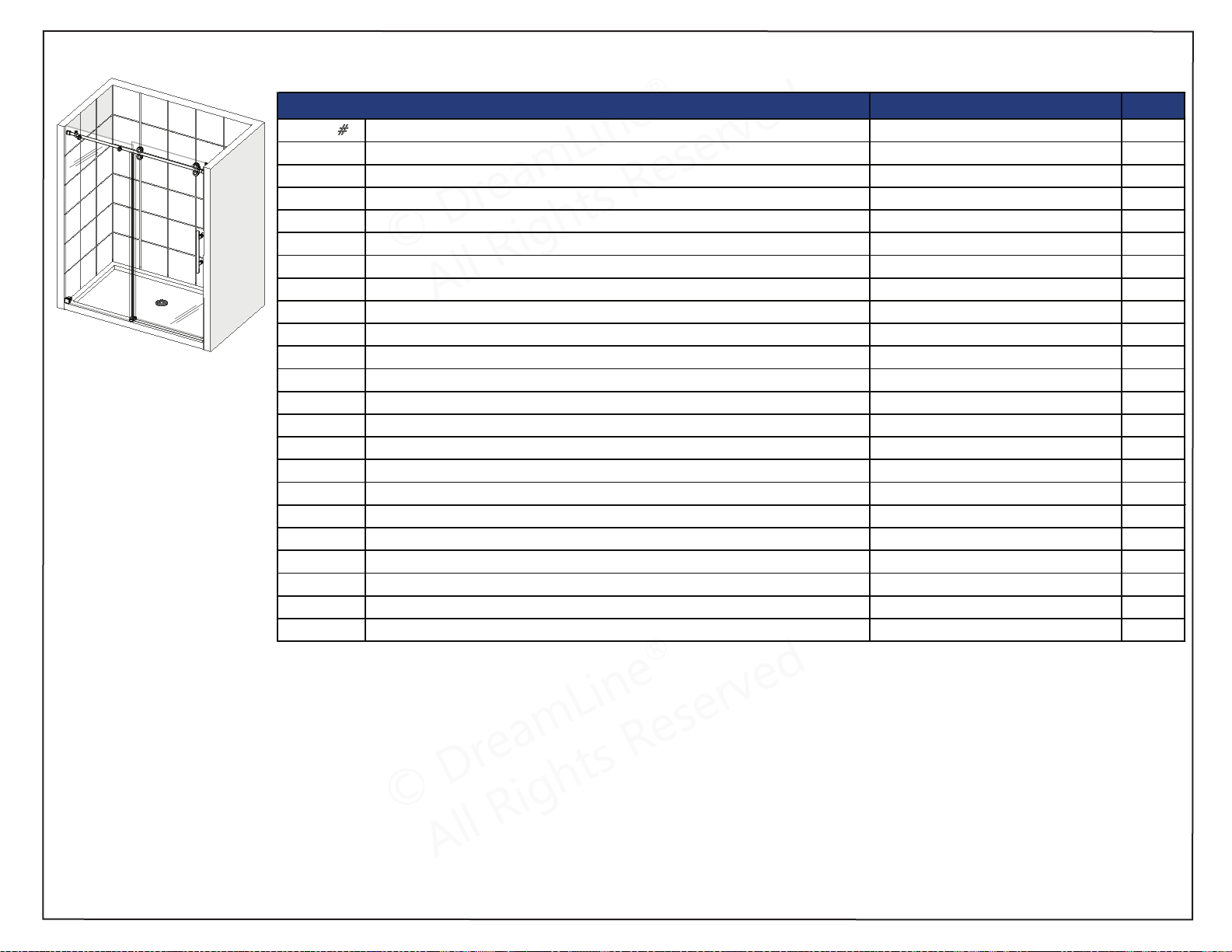
FACTORY PARTS INFORMATION
ITEM
#
FACTORY PART NUMBER ITEM DESCRIPTION QTY
01
07021036 /07025036 / 07026036 / 07029036
Door Stopper
2pcs
02
010114005
Panel Glass
1pc
03
07121036 / 07125036 / 07126036 / 07129036
Top Guide Rail
1pc
04
07351006 / 07355006 / 07356006 / 07359006
Roller Assembly
4pcs
05
010114004
Door Glass
1pc
06
07221003 / 07225003 / 07226003 / 07229003
Handle
1pc
07
07021104 / 07025104 / 07026104 / 07029104
Glass-to-Rail Bracket
2pcs
08
07021097 / 07025097 / 07026097 / 07029097
Guide Rail Bracket
2pcs
09a
07550044
Wall Anchor 3/8” (10mm)
2pcs
09b
07550045
Wall Anchor 5/16” (8mm)
3pcs
10
090112
ST6x65 Large Truss Head Screw
2pcs
11
098003 / 098004 / 098005
Allen Wrench (3mm, 4mm, 5mm)
1set
12
07021138 / 07024138 / 07026138 / 07029138
Guide Block (with caps)
1pc
13
063007100-1921
Bulb Vinyl Seal
1pc
14
063027100-1800 & 063027100-1791
Vertical Vinyl Seal
2pcs
15
04100011-736 / 04100041-736 / 04100061-736 / 04100091-736
Dam Strip
1pc
16
07551068 / 07554068 / 07556068 / 07559068
Dam Strip Cap
1pc
17
092108
ST4.2x40 Countersunk Screw
2pcs
18
090113
ST4.2x55 Truss Head Screw
1pcs
19
07021004 / 07024004 / 07026004 / 07029004
Wall Bracket
1pc
26
160012
Thread Lock Adhesive
1pc
30
07021153 / 07024153 / 07026153 / 07029153
SafeStop™ Bumper
1pc
54x76 ENIGMA-XO Shower {SHDR-61547620-##}
SHDR-51547620-##
ENIGMA-XO Shower and Tub Door Manual Ver 1 Rev 3 062019 43
© 2019 DreamLine® All Rights Reserved
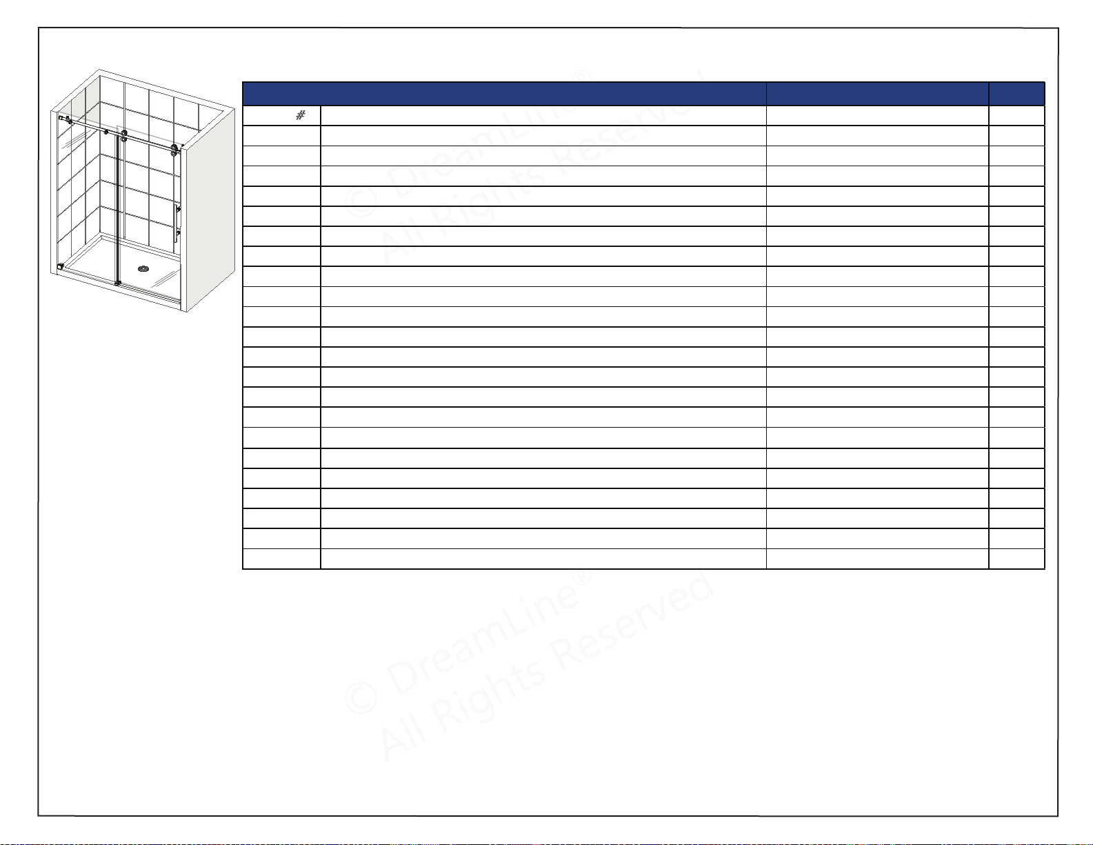
© DreamLine
®
All Rights Reserved
© DreamLine
®
All Rights Reserved
Factory Parts Information
Contact [email protected] for Part replacement, installation assistance or additional information.
Complete Warranty information is available on DreamLine.com.
BOLD digit indicates finish color:
1 or 8 = Polished SS
4 or 5 or 7 = Brushed SS
6 = Oil Rubbed Bronze
9 = Satin Black
FACTORY PARTS INFORMATION
ITEM
#
FACTORY PART NUMBER ITEM DESCRIPTION QTY
01 07021036 /07025036 / 07026036 / 07029036 Door Stopper 2pcs
02 010112002 Panel Glass 1pc
03 07121044 / 07125044 / 07126044 / 07129044 Top Guide Rail 1pc
04 07351006 / 07355006 / 07356006 / 07359006 Roller Assembly 4pcs
05 010114002 Door Glass 1pc
06 07221003 / 07225003 / 07226003 / 07229003 Handle 1pc
07 07021104 / 07025104 / 07026104 / 07029104 Glass-to-Rail Bracket 2pcs
08 07021097 / 07025097 / 07026097 / 07029097 Guide Rail Bracket 2pcs
09a 07550044 Wall Anchor 3/8” (10mm) 2pcs
09b 07550045 Wall Anchor 5/16” (8mm) 3pcs
10 090112 ST6x65 Large Truss Head Screw 2pcs
11 098003 / 098004 / 098005 Allen Wrench (3mm, 4mm, 5mm) 1set
12 07021138 / 07024138 / 07026138 / 07029138 Guide Block (with caps) 1pc
13 063007100-1921 Bulb Vinyl Seal 1pc
14 063027100-1800 & 063027100-1791 Vertical Vinyl Seal 2pcs
15 04100011-0813 / 04100041-0813 / 04100061-0813 / 04100091-0813 Dam Strip 1pc
16 07551068 / 07554068 / 07556068 / 07559068 Dam Strip Cap 1pc
17 092108 ST4.2x40 Countersunk Screw 2pcs
18 090113 ST4.2x55 Truss Head Screw 1pcs
19 07021004 / 07024004 / 07026004 / 07029004 Wall Bracket 1pc
26 160012 Thread Lock Adhesive 1pc
30 07021153 / 07024153 / 07026153 / 07029153 SafeStop™ Bumper 1pc
60x76 ENIGMA-XO Shower {SHDR-61607620-##}
SHDR-61607620-##
ENIGMA-XO Shower and Tub Door Manual Ver 1 Rev 3 062019 44
© 2019 DreamLine® All Rights Reserved

© DreamLine
®
All Rights Reserved
© DreamLine
®
All Rights Reserved
Factory Parts Information
Contact [email protected] for Part replacement, installation assistance or additional information.
Complete Warranty information is available on DreamLine.com.
BOLD digit indicates finish color:
1 or 8 = Polished SS
4 or 5 or 7 = Brushed SS
6 = Oil Rubbed Bronze
9 = Satin Black
FACTORY PARTS INFORMATION
ITEM
#
FACTORY PART NUMBER ITEM DESCRIPTION QTY
01 07021036 /07025036 / 07026036 / 07029036 Door Stopper 2pcs
02 010112002 Panel Glass 1pc
04 07351006 / 07355006 / 07356006 / 07359006 Roller Assembly 4pcs
05 010114002 Door Glass 1pc
06 07221003 / 07225003 / 07226003 / 07229003 Handle 1pc
07 07021104 / 07025104 / 07026104 / 07029104 Glass-to-Rail Bracket 2pcs
08 07021097 / 07025097 / 07026097 / 07029097 Guide Rail Bracket 2pcs
09a 07550044 Wall Anchor 3/8” (10mm) 2pcs
09b 07550
045 Wall Anchor 5/16” (8mm) 3pcs
10 090112 ST6x65 Large Truss Head Screw 2pcs
11 098003 / 098004 / 098005 Allen Wrench (3mm, 4mm, 5mm) 1set
12 07021138 / 07024138 / 07026138 / 07029138 Guide Block (with caps) 1pc
14 063027100-1800 & 063027100-1791 Vertical Vinyl Seal 2pcs
15 04100011-0770 / 04100041-0770 / 04100061-0770 / 04100091-0770 Dam Strip (for 72”) 1pc
16 07551068 / 07554068 / 07556068 / 07559068 Dam Strip Cap 1pc
17 092108 ST4.2x40 Countersunk Screw 2pcs
18 090113 ST4.2x55 Truss Head Screw 1pcs
19 07021004 / 07024004 / 07026004 / 07029004 Wall Bracket 1pc
26 160012 Thread Lock Adhesive 1pc
30 07021153 / 07024153 / 07026153 / 07029153 SafeStop™ Bumper 1pc
12x76 ENIGMA-XO Small Inline Panel Glass {SHDR-61127620-##}
FACTORY PARTS INFORMATION
ITEM
#
FACTORY PART NUMBER ITEM DESCRIPTION QTY
09b 07550045 Wall Anchor 5/16” (8mm) 2pcs
11 098003 / 098004 / 098005 Allen Wrench (3mm, 4mm, 5mm) 1set
14 063018100-1800 Vertical Vinyl Seal 1pc
18 090113 ST4.2x55 Truss Head Screw 1pc
19 07021004 / 07024004 / 07026004 / 07029004 Wall Bracket 1pc
21 07021043 / 07025043 / 07026043 / 07029043 Small Inline Panel Glass-to-Rail Bracket 1pc
22 07021005 / 07024005 / 07026005 Small Inline Panel Glass Bottom Bracket 1pc
23 010113003 Small Inline Panel Glass 1pc
24 07121045 / 07125045 / 07126045 Top Guide Rail (for 72”) 1pc
25 091107 ST4.2x40 Countersunk Screw 1pc
60x76 ENIGMA-XO Shower {SHDR-61607620-##}
SHDR-61727620-##
{SHDR-61607620-##}
(SHDR-61607620-##) +
(SHDR-61127620-##)
ENIGMA-XO Shower and Tub Door Manual Ver 1 Rev 3 062019 45
© 2019 DreamLine® All Rights Reserved
72”
MODEL
ONLY

© DreamLine
®
All Rights Reserved
© DreamLine
®
All Rights Reserved
© DreamLine
®
All Rights Reserved
© DreamLine
®
All Rights Reserved
TEL: 866-731-2244
FAX: 866-857-3638
DREAMLINE.COM
For more information on DreamLine
®
Shower Doors and Enclosures please visit DreamLine.com
©2019 DreamLine
®
All Rights Reserved