_E/,_\_ Owner's
Manual
CRRFTSHRN°
5.0 HORSEPOWER
2000 PSi 2.2 GPM
HIGH PRESSURE WASHER
Model No.
580.762012
CAUTmON: Before using this
product, read this manual and
follow all Safety Rules and
Operating Instructions.
HOURS: Mon. - Fri. 8 a.m. to 5 p.m. (CST)
SEARS, ROEBUCK and CO., Hoffman Estates,
Part Nor B34!8 Draft 0 (07/31/98)
IL 60179
U.S.A.
SAFETY RULES ............... ............. 3
ASSEMBLY .............................. 4-5
OPERATION ............................ 6-10
MAINTENANCE ........................ 11-t4
STORAGE ............................... t 5
TROUBLESHOOTING ....................... 16
REPLACEMENT PARTS .................. 18-33
HOW TO ORDER PARTS . . . ................. 34
LIMITED ONE YEAR WARRANTY ON CRAFTSMAN HIGH PRESSURE WASHER
For one year from the date of purchase, when this Craftsman High Pressure Washer is maintained and operat-
ed according to the instructions in the owner's manual, Sears will repair, free of charge, any defect in material
and workmanship.
If this high pressure washer is used for commercial purposes, this warranty applies for only 90 days from the
date of purchase. If this high pressure washer is used for rental purposes, this warranty applies for only 30
days after date of purchase.
This warranty does not cover:
• Expendable items such as spark plugs and air filters, which become worn during normal use.
. Repairs necessary because of operator abuse or negligence, including damage resulting from no water being
supplied to pump or failure to maintain the equipment according to the instructions contained in the owner's
manual.
WARRANTY SERVICE IS AVAILABLE BY RETURNING THE HIGH PRESSURE WASHER TO THE
NEAREST SEARS SERVICE CENTER OR DEALER IN THE UNITED STATES,
This warranty gives you specific legal rights and you may also have other rights, which vary from state to
state.
SEARS, ROEBUCK AND CO., D/817 WA, Hoffman Estates, IL 60179
CAUTION: ALWAYS DISCONNECT SPARK PLUG WiRE AND PLACE WIRE WHERE IT CAN- ]
NOT CONTACT SPARK PLUG, TO PREVENT ACCIDENTAL STARTING WHEN SETTING UP,
TRANSPORTING, ADJUSTING OR MAKING REPAIRS TO YOUR HIGH PRESSURE WASHER.
{_ AUTtON: Before using this product,
read this manual and follow all Safety
Rules and Operating Instructions.
• Engine exhaust gases contain DEADLY carbon monoxide
gas. This dangerous gas, if breathed in sufficient concen-
trations, can cause unconsciousness or even death.
Operate this equipment only inthe open air where ade-
quate ventiIatien is availabfe.
o Gasotine is highly FLAMMABLE and its vapors are
EXPLOSIVE. Do not permit smoking, open flames, sparks
e
or heat inthe vicinity while handling gasoline. Avoid
spilling gasoline on a hot engine. Ailow unit to cool for 2
Q
minutes before refueling. Comply with all laws regulating
storage and handling of gasoline.
• The muffler and engine will heat up during operation and
remain hot immediately after shutting itdown. Avoid any
contact with a hot muffler or engine or you coutd be
severely burned, o
• The high pressure equipment is designed to be used with
Sears authorized parts only. If you use this equipment with
parts that do not complywith minimum specifications, the
user assumes all risksand liabilities. *
• Operate engine only at governed speed. Running engine
at excessive speeds increasesthe hazard of personal °
injury. Do not tamper with parts which may increase or
decrease the governed speed, o
o Before starting the Pressure Washer in cold weather,
check attparts of the equipment and be sure ice has not °
formed there. °
• The muffier andair cieaner must be installed and in good
condition before operating the Pressure Washer. These
components act as spark arrestors if the engine backfires.
- Check fuel system for leaks or signs of deterioration such
as chafed or spongy hose, loose or missing clamps or
damaged tank or cap. Correct all defects before operating o
the PressureWasher.
. Units with broken or missing parts, or without protective
housing or covers should NEVER be operated.
• Do not adjust unloader valve to a pressure in excess of
machine rating.
• Operate the pressure at no more than the PSI fluid
pressure rated for your pressure washer,
o High pressure spray can cause paint chips or other
particles to become airborne and fly at high speeds.
• High pressure spray may damage fragile items including
glass. Do net point spray gun at glasswhen in the jet
spray mode.
o Never move the machine by pulling on the high pressure
hose. Use the handle provided on the top of the unit.
, Keep the hose connected to machine or the spray gun
while the system is pressurized. Disconnecting the hose
while the unit is pressurized is dangerous.
• Nways be certain the spray gun, nozzles and accessories
are correctly attached,
o Hold the spray gunfirmly in your hand before you start the
unit. Failure to do so could result in an injury from a whip-
ping spray gun. Do not leave the spray gun unattended
while the machine is running.
o Never use a spray gun which does not have a trigger lock
or trigger guard in place and in working order.
, Do not secure trigger gun in the pull-back (open) position.
o Keep water spray away from electric wiring Orfatal electric
shock may result.
o The cleaning area should have adequate slopes and
drainage to reduce the possibility of a fall due to slippery
surfaces.
Locate this pressure washer in areas away from any
combustible materials, combustible fumes or dust.
Do not sprayflammable liquids.
Some chemicals or detergents may be harmful if inhaled
or ingested, causing severe nausea, fainting or poisoning.
These harmful elements may also cause property damage
or severe injury,
Use a respirator or mask whenever there is a chance that
vapors may be inhaled, Read all instructions with the mask
so you are certain the mask will provide the necessary pro-
tection against inhaling harmful vapors.
Alwayswear eye protectionwhen you usethis equipmentor
when youare inthe vicinitywherethe equipmentisin use.
Do not wear loose clothing, jewelry or anything that may
be caught in the starter or other rotating parts.
Do not allow CHILDREN to operate the Pressure Washer
at any time.
Never aim the gun at people, animals or plants.
This equipment produces high pressure streams of fluid
which can pierce the skin and its underlying tissues,
leading to serious injury and possible amputation.
Neverallow any part of the body to come in contact with
the fluid stream. DO NOT come in contact with a fluid
stream created by aleak in the high pressure hose.
Do not by-pass any safety device on this machine.
MAINTENANCE AND STORAGE:
• Operate and store this unit on a stable surface.
• High pressure hose can develop leaks from wear, kinking,
abuse, etc. Water spraying from a leak is capable of inject-
ing material into skin. inspect hose each time before using
it. Check all hoses for cuts, leaks, abrasions or bulging of
cover, or damage or movement of couplings. If any of
these conditions exist, replacehose immediately, Never
repair high pressure hose. Replace it with another hose
that meets minimum pressure rating of your pressure
washer,
LOOK FOR THIS SYMBOL TO POINT OUT IMPORTANT SAFETY PRECAUTIONS.
IT MEANS "ATTENTION!!! BECOME ALERT!!! YOUR SAFETY IS INVOLVED."
3
CARTON CONTENTS
The following parts are shipped loose with your pressure
washer. Before assembling, become familiar with each
piece.
Check all carton contents against the listing below:
Main Unit:
° Pressure Washer (w/wheels).
• High Pressure Hose
Parts Box:
oAdjustable Nozzle
° Turbo Nozzle
• Spray Gun
° Nozzle Extension
° Wire Form
° Motor Oil
Manual Bag:
• Owner's Manual
• Nozzle Cleaning Kit
° "O"-Ring Kit
If any parts are missing or damaged, call the Pressure
Washer Helpline at t-800-222-3136.
HOW TO REMOVE THE HIGH PRESSURE
WASHER FROM CARTON
° Remove parts boxes includedwith pressurewasher.
The high pressure hose is packed in the bottom of the
carton. Remove the hose.
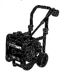
Slice two corners at handle end of carton, from top to
bottom, so the panel can be folded down flat.
Raise handle, secure in place with the locking caps
(refer to illustration below) and roll the pressure
washer out the open end of the carton.
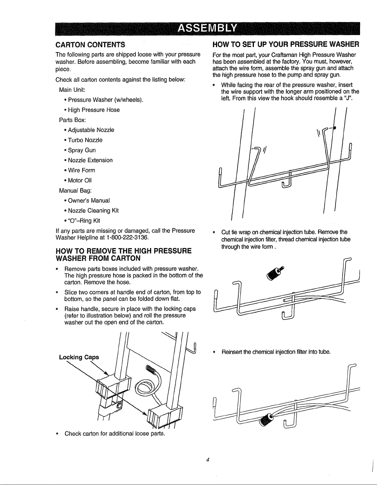
HOW TO SET UP YOUR PRESSURE WASHER
Forthe most part, yourCraftsman High Pressure Washer
has been assembledat the factory. You must,however,
attachthe wireform, assemblethe spray gunand attach
the highpressurehoseto the pumpand spray gun.
• While facing the rear of the pressure washer, insert
the wire support with the longer arm positioned on the
left. From this view the hook should resemble a "J".
• Cut tie wrapon chemical injectiontube.Remove the
chemical injectionfilter, thread chemical injection tube
through the wire form.
Locking Caps
Check carton for additional loose parts.
• Reinsert the chemical injectionfilter intotube.
4
i
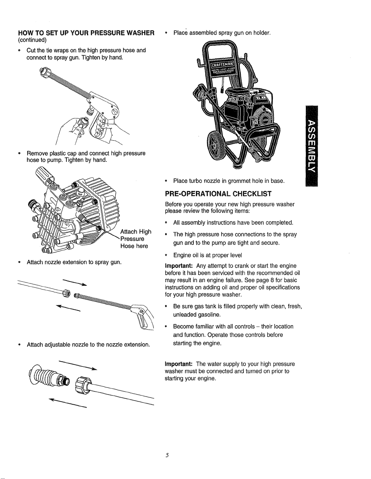
HOW TO SET UP YOUR PRESSURE WASHER
(continued)
• Cut the tie wrapson the high pressurehose and
connect to spray gun. Tighten by hand.
g Place assembled spray gun on holder.
o Remove plastic cap and connect high pressure
hose to pump. Tighten by hand.
i
Hic
Hose here
Attach nozzle extension to spray gun.
"*-==_..,,=.
Attach adjustable nozzle to the nozzle extension.
, Place turbo nozzle in grommet hole in base.
PRE-OPERATIONAL CHECKUST
Before you operate your new high pressure washer
please review the following items:
, All assembly instructions have been completed.
, The high pressure hose connections to the spray
gun and to the pump are tight and secure.
, Engine oil is at proper level
Important: Any attempt to crank or start the engine
before it has been serviced with the recommended oil
may result in an engine failure. See page 8 for basic
instructions on adding oil and proper oil specifications
for your high pressure washer.
o Be sure gas tank is filled properly with clean, fresh,
unleaded gasoline.
, Become familiar with all controls - their location
and function. Operate those controls before
starting the engine.
Important: The water supply to your high pressure
washer must be connected and turned on prior to
starting your engine.
5
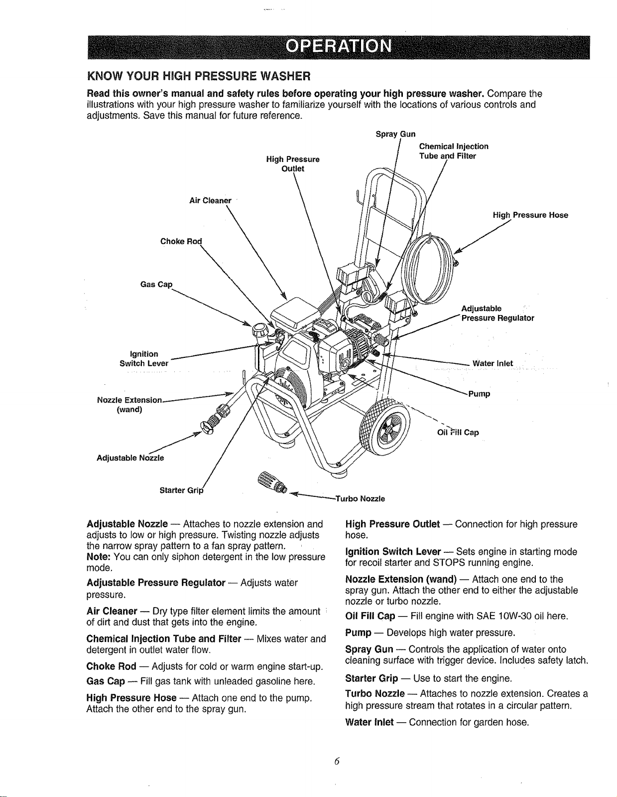
KNOW YOUR HnGH PRESSURE WASHER
Read this owner's manual and safety rules before operating your high pressure washer. Compare the
illustrations with your high pressure washer to familiarize yourself with the locations of various controls and
adjustments. Save this manual for future reference.
High Pressure
Outlet
Spray Gun
Chemical Injection
Tube and Filter
Air Cleaner
Pressure Hose
Choke Rod
Adjustable '
Regulator
ignition
Switch Lever Water Inlet
Nozzle Exte=
(wand)
_Turbo Nozzle
Adjustable Nozzle /
Starter Grip
_Pump
Oil FillCap
Adjustable Nozzle -- Attaches to nozzle extension and
adjusts to low or high pressure.Twisting nozzle adjusts
the narrow spray patternto a fan spray pattern,
Note: You can only siphon detergent in the low pressure
mode.
Adjustable Pressure Regulator -- Adjusts water
pressure,
Air Cleaner -- Dry type filter element limits the amount
of dirt and dust that gets intothe engine.
Chemical Injection Tube and Filter -- Mixes water and
detergent in outlet water flow.
Choke Rod -- Adjusts for cold or warm engine start-up.
Gas Cap -- Fill gas tank with unleaded gasoline here,
High Pressure Hose -- Attach one end to the pump.
Attach the other end to the spray gun.
High Pressure Outlet -- Connection for high pressure
hose.
Ignition Switch Lever -- Sets engine in starting mode
for recoil starter and STOPS running engine.
Nozzle Extension (wand) -- Attach one end to the
spray gun. Attach the other end to either the adjustable
nozzle or turbo nozzle.
Oil Fill Cap -- Fill engine with SAE 10W-30 oit here.
Pump -- Devetops high water pressure.
Spray Gun -- Controls the application of water onto
cieaning surface with trigger device. Includes safety latch,
Starter Grip -- Use to start the engine,
Turbo Nozzle -- Attaches to nozzle extension. Creates a
high pressure stream that rotates in a circular pattern,
Water Inlet -- Connection for garden hose.
HOW TO USE YOUR PRESSURE WASHER
-IF YOU HAVE ANY PROBLEMS operating your
pressure washer, please call the pressure washer
helpline at 1-800-222-3136.
_, DANGER! NEVER adjust spray pattern
when spraying. NEVER put hands in front
of spray nozzle to adjust spray pattern.
You could be injured,
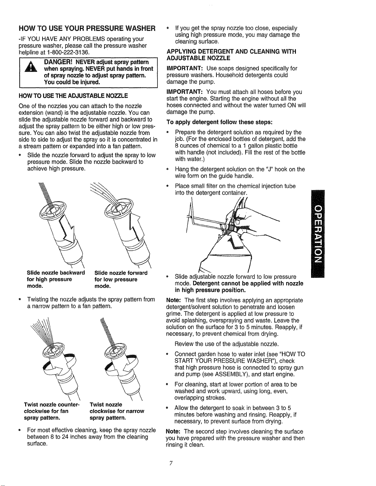
HOW TO USE THE ADJUSTABLE NOZZLE
One ofthe nozzles you can attach to the nozzle
extension (wand) isthe adjustable nozzle. You can
slide the adjustable nozzle forward and backward to
adjust the spray pattern to be either high or low pres-
sure. You can also twist the adjustable nozzle from o
side to side to adjust the spray so it is concentrated in
a stream pattern or expanded into a fan pattern.
• Slide the nozzle forward to adjust the spray to low
pressure mode. Slide the nozzle backward to
achieve high pressure. •
, If you get the spray nozzle too close, especially
using high pressure mode, you may damage the
cleaning surface.
APPLYING DETERGENT AND CLEANING WITH
ADJUSTABLE NOZZLE
IMPORTANT: Use soaps designed specifically for
pressure washers. Household detergents could
damage the pump.
IMPORTANT: You must attach all hoses before you
start the engine. Starting the engine without all the
hoses connected and without the water turned ON will
damage the pump.
To apply detergent follow these steps:
Prepare the detergent solution as required by the
job. (For the enclosed bottles of detergent, add the
8 ounces of chemical to a 1 gallon plastic bottle
with handle (not included). Fill the rest of the bottle
with water.)
Hang the detergent solution on the "J" hook on the
wire form on the guide handle.
Place small filter on the chemical injection tube
intothe detergent container.
Slide nozzle backward
for high pressure
mode.
Slide nozzle forward
for low pressure
mode.
Twisting the nozzle adjusts the spray patternfrom
a narrow pattern to a fan pattern.
Twist nozzle counter-
clockwise for fan
spray pattern.
Twist nozzle
clockwise for narrow
spray pattern,
For most effective cleaning, keep the spray nozzle
between 8 to 24 inches away from the cleaning
surface.
• Slide adjustable nozzle forward to low pressure
mode. Detergent cannot be applied with nozzle
in high pressure position.
Note: The first step involves applying an appropriate
detergent/solvent solution to penetrate and loosen
grime. The detergent is applied at low pressure to
avoid splashing, overspraying and waste. Leave the
solution on the surface for 3 to 5 minutes. Reapply, if
necessary, to prevent chemical from drying.
Review the use of the adjustable nozzle.
Connect garden hose to water inlet (see "HOW TO
START YOUR PRESSURE WASHER"), check
that high pressure hose is connected to spray gun
and pump (see ASSEMBLY), and start engine.
• For cleaning, start at lower portion of area to be
washed and work upward, using long, even,
overlapping strokes.
, Allow the detergent to soak in between 3 to 5
minutes before washing and rinsing. Reapply, if
necessary, to prevent surface from drying.
Note: The second step involves cleaning the surface
you have prepared with the pressure washer and then
rinsing it clean.
?
BEFORE STARTING THE PRESSURE WASHER
WARNING: Improperlymaintainingthis engine
or failing to correcta problembeforeoperation
couldcausea malfunctioninwhichyoucouldbe
seriously injured.
Always perform a we-operation inspection
before eachoperationand correctany problem.
Note: It is importantbefore you operate the pressure
washer to check the condition of the engine. Check for
signs of any gas or oil leaks. Check that all of the shields
and covers are in place, and all nuts, bolts and screws
are tightened.
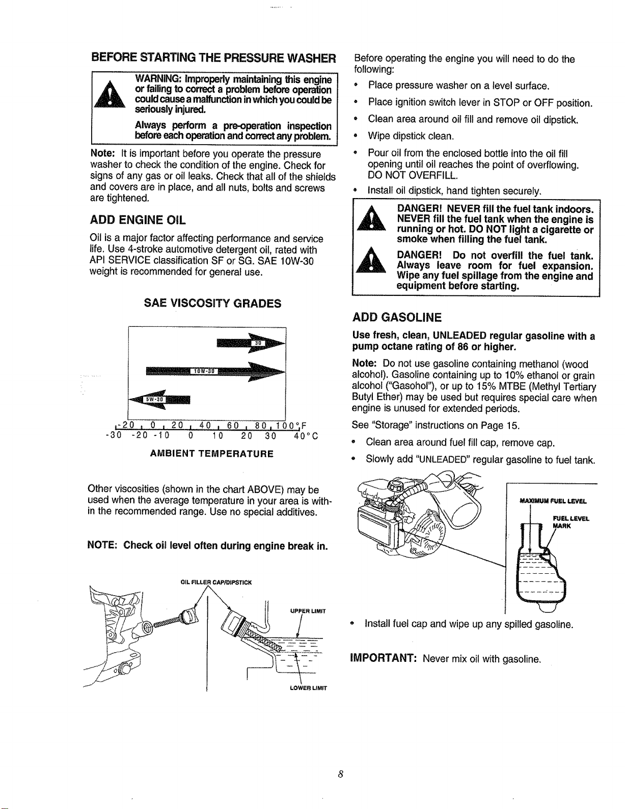
ADD ENGINE OtL
Oil isa major factor affecting performance and service
life. Use 4-stroke automotive detergent oil, rated with
API SERVICE classification SF or SG. SAE 10W-30
weight is recommended for general use.
SAE VISCOSITY GRADES
V
,'20 t 0 = 20 I 40 i 60 i 80,100°F
"30 "20 "t0 0 10 20 30 40°C
AMBIENT TEMPERATURE
Other viscosities (shown in the chart ABOVE) may be
used when the average temperature in your area is with-
in the recommended range. Use no special additives.
NOTE: Check oil level often during engine break in.
OIL RLLER CAP[DIPSTICK
,\
Before operating the engine you will need to do the
following:
o Place pressure washer on a Ievel surface.
= Place ignition switch lever in STOP or OFF position.
• Clean area aroundoilfill and remove oildipstick.
° Wipe dipstickclean.
o Pouroilfrom the enclosed bottle intothe oilfill
opening untiloil reaches the point of overflowing.
DO NOT OVERFILL.
install oildipstick,hand tightensecurely.
DANGER! NEVER fill the fuel tank indoors.
NEVER fill the fuel tank when the engine is
running or hot. DO NOT light a cigarette or
smoke when filling the fuel tank.
DANGER! Do not overfill the fuel tank.
Always leave room for fuel expansion.
Wipe any fuel spillage from the engine and
equipment before starting.
ADD GASOLINE
Use fresh, clean, UNLEADED regular gasoline with a
pump octane rating of 86 or higher.
Note: Do not use gasoline containing methanol (wood
alcohol). Gasoline containing up to 10% ethanol or grain
alcohol ("Gasohol"), or up to 15% MTBE (Methyl Tertiary
Butyl Ether) may be used but requires special care when
engine is unused for extended periods.
See "Storage" instructions on Page 15.
• Clean area around fuel fill cap, remove cap.
° Slowly add "UNLEADED"regular gasoline to fuel tank.
Install fuel cap and wipe up any spilled gasoline.
LOWER UMIT
IMPORTANT: Never mix oil with gasoline,
,RINSING WiTH THE PRESSURE WASHER
WARNING Be extremely careful if you
must use the pressure washer from ladder,
scaffolding or any other relatively unstable
location. Pressure in a running washer builds
in the wand as you climb. When you press
the trigger, the recoil from the initial spray
could force you to fall, or if you are too close
to the cleaning surface, high pressure could
force you off a climbing apparatus.
Hook up the water supply and start your pressure
washer (see HOW TO START YOUR PRESSURE
WASHER).
Slide adjustable nozzle back to high pressure position
and wait for detergent to clear. Detergent will not flow
when in the high pressure mode.
• When detergent has cleared you may want to expand
the spray pattern for a more gentle rinsing action.
Start at top of area to be rinsed, working down with
same action as for cleaning.
You can also stop detergent from flowing by simply
removing the siphon from bottle.
HOW TO ADJUST PRESSURE USING THE
PRESSURE CONTROL KNOB
Located on the pump isa pressure control knob. You can
increase and decrease the pressure of the spray by turn-
ing the knob clockwise or counterclockwise respectively.
The knob is set at maximum pressure at the factory.
HOW TO USE THE TURBO NOZZLE.
The turbo nozzle rotates the high pressure stream in a
rapid circular pattern. This increases the cleaning effec-
tiveness of the high pressure spray. Attach the turbo
nozzle on the end of the nozzle extension.
The high pressure spray is most effective when the tip of
the wand is held between 8 to 24 inches from the surface
being cleaned.
Important: The turbo nozzle produces an extremely
high pressure spray which is capable of removing paint
and cutting holes through cleaning surfaces if held too
close. Always make sure the surface you clean will not
be damaged by the high pressure spray.
HOW TO START YOUR PRESSURE WASHER
You have assembled your high pressure washer and
have prepared the engine for starting. You are now ready
to clean your car, boat or whatever you plan to clean.
Place pressure washer in an area close enough to an
outside water source that flows at a rate of at least 2.5
gallons per minute. Connect a garden hose to the
water spout.
Check that high pressure hose is tightly connected to
spray gun and pump. See ASSEMBLY section.
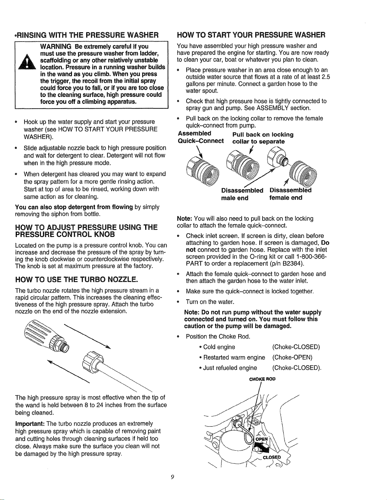
Assembled
Quick-Connect
Pull back on the locking collar to remove the female
quick-connect from pump.
Putt back on locking
collar to separate
Disassembled Disassembled
male end female end
Note: You will also need to pull back on the locking
collar to attach the female quick-connect.
®
Check inlet screen, if screen is dirty, clean before
attaching to garden hose. If screen is damaged, Do
not connect to garden hose. Replace with the inlet
screen provided in the O-ring kit or call 1-800-366-
PART to order a replacement (p/n B2384).
Attach the female quick-connect to garden hose and
then attach the garden hose to the water inlet.
Make sure the quick-connect is locked together.
Turn on the water.
Note: Do not run pump without the water supply
connected and turned on. You must follow this
caution or the pump will be damaged.
Position the Choke Rod.
• Cold engine
• Restarted warm engine
• Just refueled engine
(Choke-CLOSED)
(Choke-OPEN)
(Choke-CLOSED).
CHOKE ROD
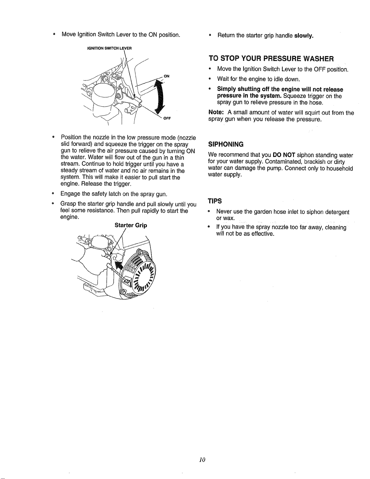
• Move Ignition Switch Lever tothe ON position. = Return the starter grip handle slowly.
o
°
IGNITION SWITCH LEVER
Position the nozzle in the low pressure mode (nozzle
stid forward) and squeeze the trigger on the spray
gun to relieve the air pressure caused by turning ON
the water. Water witl flow out of the gun in a thin
stream. Continue to hold trigger until you have a
steady stream of water and no air remains in the
system. This will make it easier to pull start the
engine. Release the trigger.
Engage the safety latch on the spray gun.
Grasp the starter grip handle and pull slowly until you
feel some resistance. Then pull rapidly to start the
engine.
Starter Grip
TO STOP YOUR PRESSURE WASHER
, Move the ignitionSwitch Lever to the OFF position.
° Wait for the engine to idle down.
• Simply shutting off the engine will not release
pressure in the system. Squeeze triggeron the
spray gun to relieve pressure in the hose.
Note: A small amount of water will squirt out from the
spray gun when you release the pressure.
SIPHONING
We recommend thatyou DO NOT siphon standing water
for your water supply. Contaminated, brackish or dirty
water can damage the pump. Connect only to household
water supply.
TIPS
, Never use the garden hose inlet to siphon detergent
or wax.
° if you have the spray nozzle too far away, cleaning
will not be as effective.
10
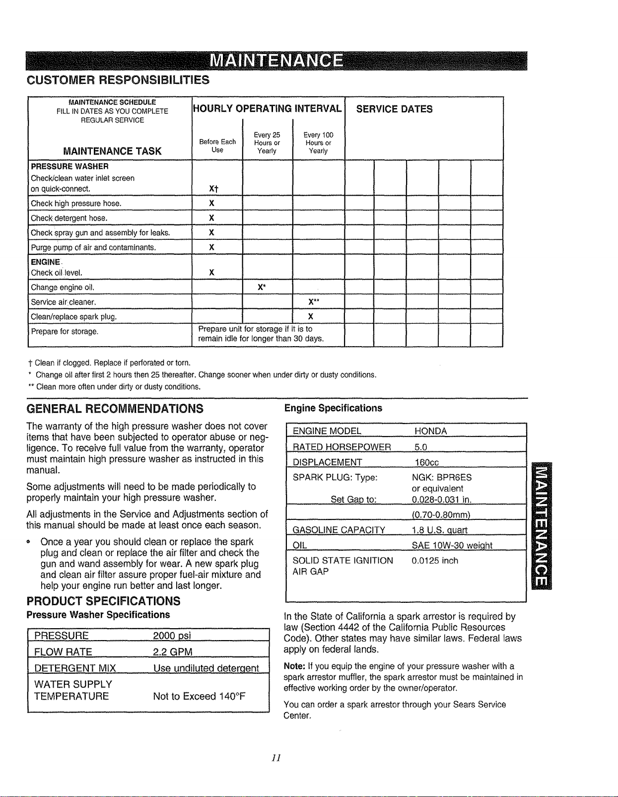
CUSTOMER RESPONSIBILITIES
MAINTENANCE SCHEDULE
FiLL IN DATES AS YOU COMPLETE
REGULAR SERVICE
MAINTENANCE TASK
"'PRESSURE WASHER
Check/clean water inlet screen
on quick-connect.
Check high pressure hose,
Check.detergent hose.
Check spray gun and assembly for leaks,
Purge PUmPof air and contaminants.
ENGINE,
iCheck oillevel.
Change engine oil,
Service air cleaner,
Clean/replace spark plug.
iPrepare for storage,
HOURLY OPERATING INTERVAL
I Every 100
Before Each Hours or
Use Yearly
Xl-
x
x
x
×
x
Every 25
Hou_s or
Yearly
X*
SERVICE DATES
x
Prepareunitfor storageifitiSto
remain idle for longer than 30 days,
I" Clean if clogged. Replace if perforated or torn,
* Change oil after first 2 hours then 25 thereafter, Change sooner when under dirty or dusty conditions.
** Clean more often under dirty or dusty conditions.
GENERAL RECOMMENDATIONS Engine Specifications
,............. " "' l '
i
The warranty of the high pressure washer does not cover
items that have been subjected to operator abuse or neg-
ligence. To receive full value from the warranty, operator
must maintain high pressure washer as instructed in this
manual.
Some adjustments wilf need to be made periodically to
properly maintain your high pressure washer,
All adjustments in the Service and Adjustments section of
this manual should be made at least once each season,
o Once a year you should clean or replace the spark
plug and clean or replace the air filter and check the
gun and wand assembly for wear, A new spark plug
and clean air filter assure proper fuel-air mixture and
help your engine run better and last longer,
PRODUCT SPECIFICATIONS
Pressure Washer Specifications
PRESSURE
FLOW RATE
DETERGENT MIX
WATER SUPPLY
TEMPERATURE
2000 psi
2.2 GPM
Use undiluted deterqent
Not to Exceed 140°F
ENGINE MODEL HONDA
RATED HORSEPOWER 5.0
DISPLACEMENT 160cc
SPARK PLUG: Type: NGK: BPR6ES
or equivalent
Set Gap to: 0,028-0,031 in.
.... (0,70-0o80mm)
GASOLINE CAPACITY 1,8 U.S, quart
OIL SAE !0W_30 weig,ht .......
SOLID STATE IGNITION 0,0125 inch
AIR GAP
In the State of California a spark arrestor isrequired by
law (Section 4442 of the California Public Resources
Code), Other states may have similar laws. Federal laws
apply on federal tands.
Note: tf you equip the engine of your pressure washer with a
spark arrestor muffler, the spark arrestor must be maintained in
effective working order by the owner/operator.
You can order a spark arrestor through your Sears Service
Center.
]]
BEFORE EACH USE
Check water inletscreen for damage.
= Check high pressure hose for leaks.
, Check detergent inlet hose and filter for damage.
e Check gun and wand assembly for leaks.
o Purge pump of air and contaminants.
, Check engine oil level.
PRESSURE WASHER MAINTENANCE
CHECK AND CLEAN INLET SCREEN
Remove quick-connect and examine inlet screen on the
female connector. Clean if clogged or replace if torn.
CHECK HIGH PRESSURE HOSE
High pressure hose can develop leaks from wear, kinking
and abuse. Inspect hose before each use. Check for cuts,
leaks, abrasions or bulging of cover, or damage or move-
ment of couplings. If any of these conditions exist,
replace hose immediately.
DANGER: Water spraying from a leak is
capable of injecting material into skin.
NEVER repair high pressure hose, Replace
with hose that meets minimum pressure
rating of your pressure washer.
CHECK DETERGENT HOSE
Examine the filter on the hose and clean if clogged. Hose
should fit tightly on barbed fitting. Examine for leaks or
tears. Replace the filter or hose if either is damaged.
CHECK SPRAY GUN AND WAND
Examine hose connectionto spray gunand make sure it
is secure. Test trigger by pressing it and making sure it
springs back into place when released. Put the safety
latch in the UP position and test trigger. You should not
be able to press the trigger.
PURGE PUMP OF AIR AND CONTAMINANTS
To remove the air from the pump:
• Set up the pressure washer as described in the
ASSEMBLY section and connectthe water supply.
• Remove the nozzle extension from the spray gun.
o Pull the trigger on the gun and hold.
To remove contaminants from the pump:
o Set up the pressure washer as described in the
ASSEMBLY section, and connect the water supply.
o Remove the nozzle attachment from the spray gun.
• Start engine according to OPERATION instructions.
° Pull the trigger on the spray gun and hold.
• When the water supply is steady, engage the safety
latch and refasten the nozzle attachment.
ENGINE MAINTENANCE
CHECKING OIL LEVEL
Oil level should be checked before each use, and at least
after every 5 hours of operation as follows:
• Check the engine oil level with the engine stopped
and in a level position.
• Remove the oil filler cap/dipstick and wipe it clean.
• Insert and remove the dipstick without screwing it into
the filler neck. Check the oil level shown on the dip-
stick.
• if the oil level is low, fill to the edge of the oil filler hole
with the recommended oil. (See page 8)
Reinstall the oil filler cap.
CHANGING ENGINE OIL
Change engine oil after first 2 hours then every 25 hours
thereafter, tf you are using your pressure washer under
extremely dirty or dusty conditions, or in extremely hot
weather, change the oil more often.
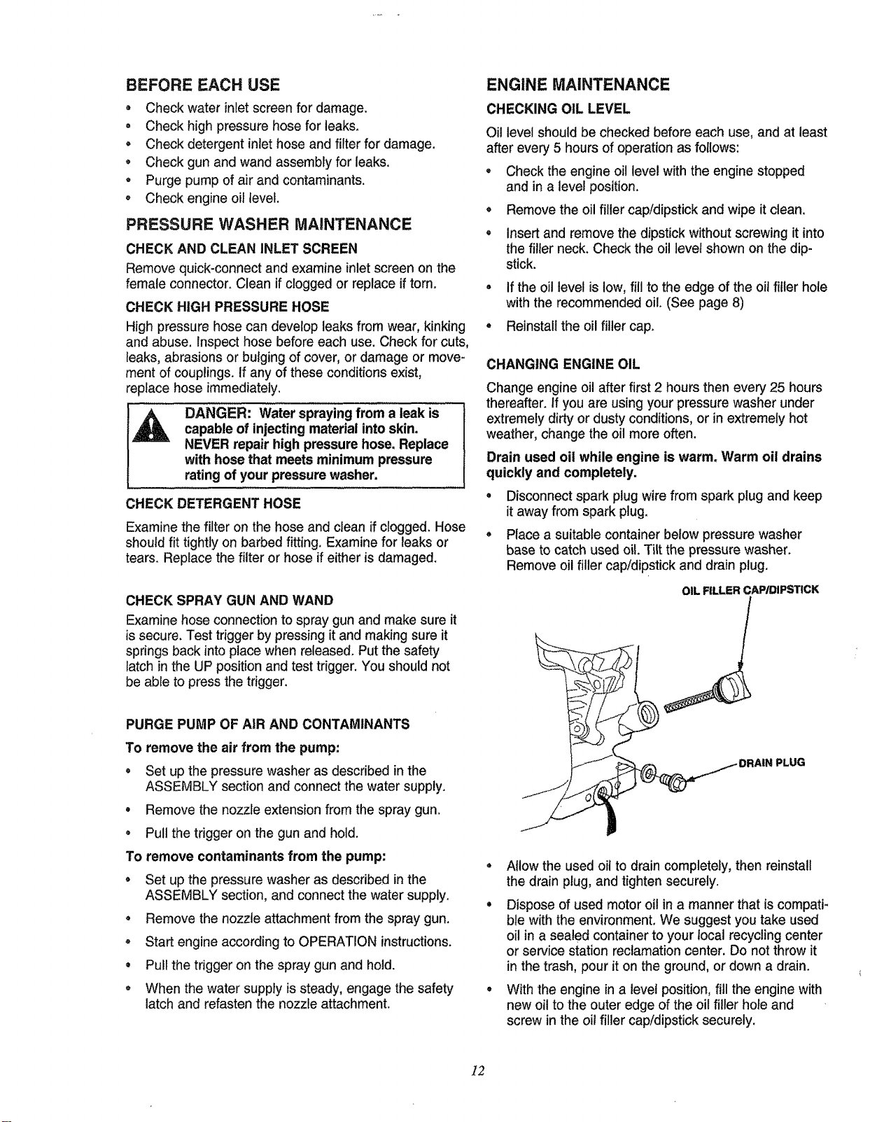
Drain used oil while engine is warm. Warm oil drains
quickly and completely.
• Disconnect spark plug wire from spark plug and keep
it away from spark plug.
• Place a suitable container below pressure washer
base to catch used oil. Tilt the pressure washer.
Remove oil filler cap/dipstick and drain plug.
OIL FILLER CAP/DIPSTICK
b
_PLUG
Allow the used oil to drain completely, then reinstall
the drain plug, and tighten securely.
Dispose of used motor oil in a manner that is compati-
ble with the environment. We suggest you take used
oil in a sealed container to your local recycling center
or service station reclamation center, Do not throw it
in the trash, pour it on the ground, or down a drain.
With the engine in a level position, fill the engine with
new oil to the outer edge of the oil filler hole and
screw in the oil filler cap/dipstick securely.
]2
SERVICING THE AIR CLEANER
Your engine will not run properly and may be damaged
ifyou run itwith a dirty air cleaner.
Replace air cleaner once every 100 hours of operation
or once each year, whichever comes first.
Replace more often ifoperating under dirty or dusty
conditions. Replacements are available at your local
Sears Authorized Service Center.
Important: Operating your pressure washer without
a complete air cleaner installed will allow dirt to enter
the engine, causing rapid engine wear. This type of
damage is not covered by warranty.
To clean or replace the air cleaner, follow these
steps:
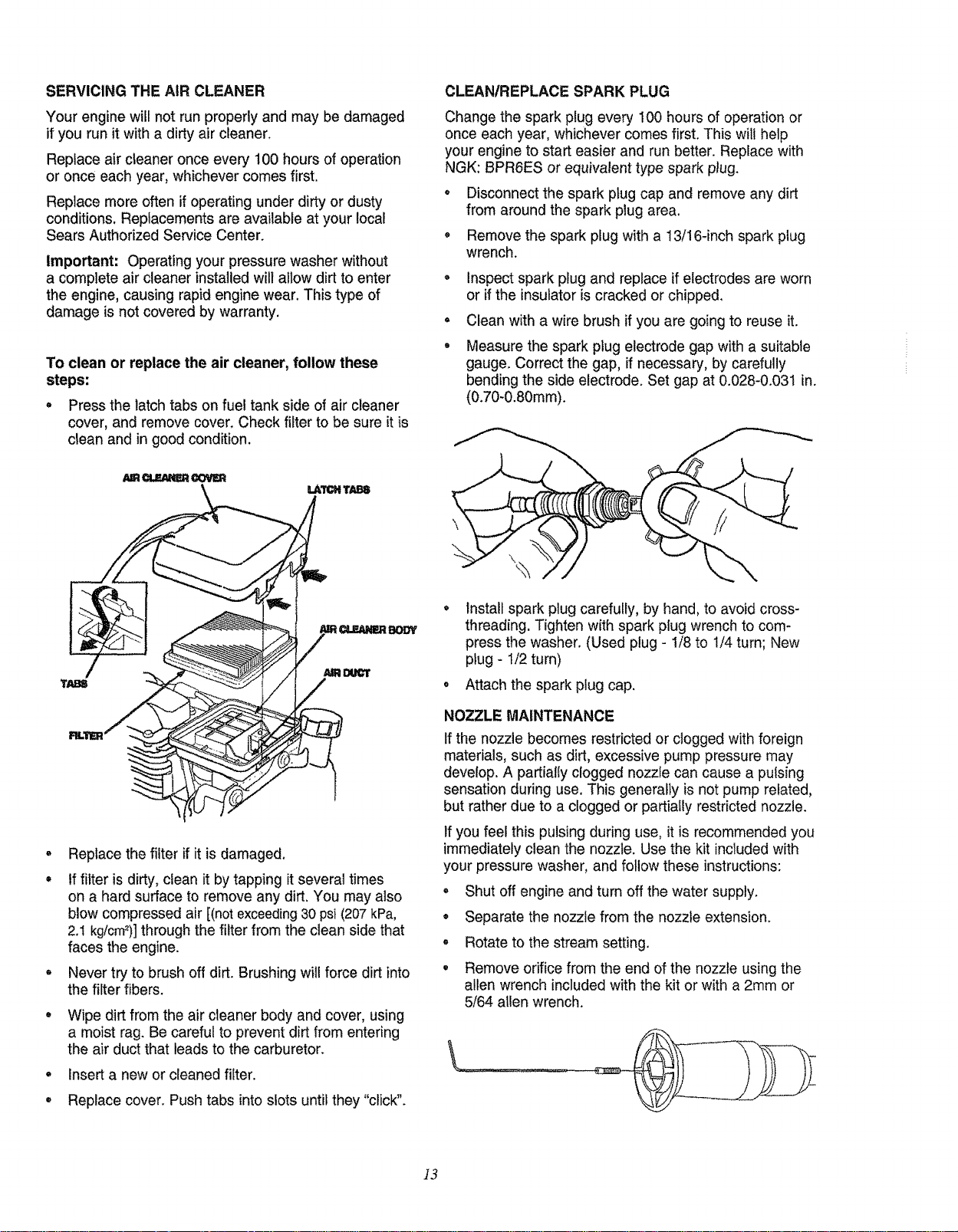
, Press the latch tabs on fuel tank side of air cleaner
cover, and remove cover. Check filter to be sure it is
clean and in good condition.
/UR_ _3"tqm
CLEANIREPLACE SPARK PLUG
Change the spark plug every 100 hours of operation or
once each year, whichever comes first. This will help
your engine to start easier and run better. Replace with
NGK: BPR6ES or equivalent type spark plug.
• Disconnect the spark plug cap and remove any dirt
from around the spark plug area.
, Remove the spark plug with a 13/16-inch spark plug
wrench.
o
o
Inspect spark plug and replace if electrodes are worn
or if the insulatoris cracked or chipped.
Clean with a wire brush if you are going to reuse it.
Measure the spark plug electrode gap with a suitable
gauge. Correct the gap, if necessary, by carefully
bending the side electrode. Set gap at 0.028-0.031 in.
(0.70-0.80ram).
o
o
o
o
Replace the filter if it is damaged.
If filter is dirty, clean itby tapping it several times
on a hard surface to remove any dirt. You may also
blow compressed air [(not exceeding30 psi (207kPa,
2.1 kg/cm=)]through the filter from the clean side that
faces the engine.
Never try to brush off dirt. Brushing will force dirt into
the filter fibers.
Wipe dirt from the air cleaner body and cover, using
a moist rag. Be careful to prevent dirt from entering
the air duct that leads to the carburetor.
insert a new or cleaned filter.
Replace cover. Push tabs into slots until they "click".
BODY
install spark plug carefully, by hand, to avoid cross-
threading. Tighten with spark plug wrench to com-
press the washer. (Used plug - !/8 to 1/4 turn; New
plug - 1/2 turn)
Attach the spark plug cap.
NOZZLE MAINTENANCE
If the nozzle becomes restricted or clogged with foreign
materials, such as dirt, excessive pump pressure may
develop. A partially clogged nozzle can cause a pulsing
sensation during use. This generally is not pump related,
but rather due to a clogged or partially restricted nozzle.
If you feel this pulsing during use, it is recommended you
immediately clean the nozzle. Use the kit included with
your pressure washer, and follow these instructions:
e
o
o
o
Shut off engine and turn off the water supply.
Separate the nozzle from the nozzle extension.
Rotate to the stream setting.
Remove orifice from the end of the nozzle using the
allen wrench included with the kit or with a 2mm or
5/64 allen wrench.
\
]3
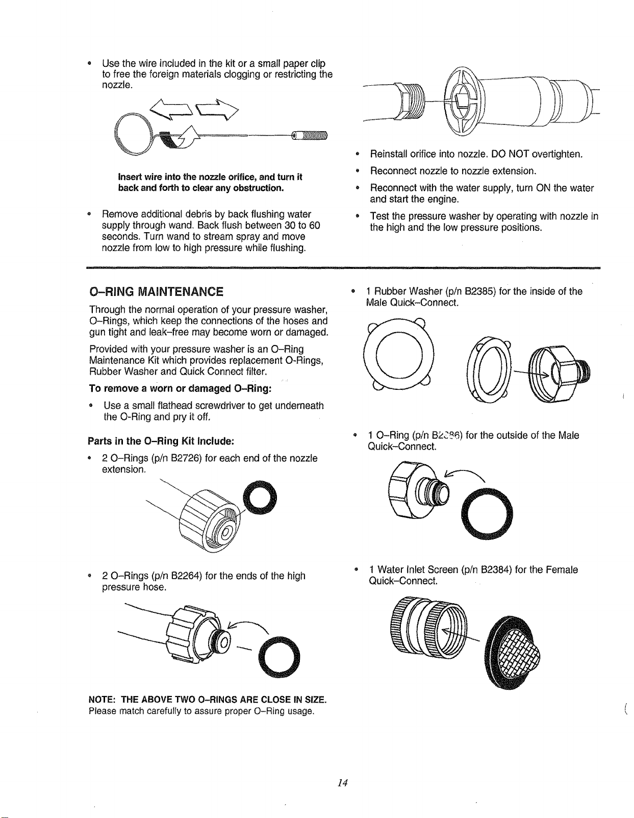
• Use the wire included inthe kit or a small paper clip
to free the foreign materials clogging or restricting the
nozzle.
Insertwire intothe nozzle orifice,andturn it
back and forth to clear anyobstruction.
Remove additional debris by back flushing water
supply through wand. Back flush between 30 to 60
seconds. Turn wand to stream spray and move
nozzle from low to high pressure while flushing.
* Reinstall orifice into nozzle. DO NOT overtighten.
o Reconnect nozzle to nozzle extension.
, Reconnect with the water supply, turn ON the water
and start the engine.
, Test the pressure washer by operating with nozzle in
the high and the low pressure positions.
O-RING MAaNTENANCE
Through the normal operation of your pressure washer,
O-Rings, which keep the connections of the hoses and
gun tight and leak-free may become worn or damaged.
Provided with your pressure washer is an O-Ring
Maintenance Kit which provides replacement O-Rings,
Rubber Washer and Quick Connect filter.
To remove a worn or damaged O-Ring:
= Use a small flathead screwdriver to get underneath
the O-Ring and pry it off.
Parts in the O-Ring Kit Include;
* 2 O-Rings (pin B2726) for each end of the nozzle
extension.
1 Rubber Washer (pin B2385) for the inside of the
Male Quick-Connect.
* 1 O-Ring (p/n B2C76) for the outside of the Male
Quick-Connect.
O
, 2 O-Rings (pin 82264) for the ends of the high
pressure hose.
• 1 Water Inlet Screen (p/n B2384) for the Female
Quick-Connect.
NOTE: THE ABOVE TWO O-RINGS ARE CLOSE IN SIZE.
Ptease match carefully to assure proper O-Ring usage,
]4
AFTER EACH USE
Water should not remain in the unit for long periods of time.
Sediments of minerals can deposit on pump partsand
"freeze"pump action. Follow these procedures after every
use:
Flush detergent hose by placing the injector filter into
a pail of clear waterwhile running Pressure Washer
with nozzle in low pressure mode. Flush until you can
see clear water running through the tube.
Shut off the engine and let it cool, then remove all
hoses.
CAUTION: Be sure ignition switch lever is
in "STOP" position before you continue, if
you start engine without the proper water
supply connected, you can damage the
pump_
Empty the pump of all pumped liquids by pulling recoil
handle about 6 times. This should remove most of the
liquid in the pump.
Coil the high pressure hose and inspect it for damage.
Cuts in the hose or fraying of it could result in leaks
and loss of pressure. Should any damage be found,
replace hose. DO NOT attempt to repair a damaged
hose. Replace hose with the genuine Craftsman part.
Drain water from hose and properly hang it on the
wire support provided on the guide handle.
Store in a clean, dry area.
DANGER: NEVER store engine with fuel in
tank indoors or in enclosed, poorly ventilat-
ed areas where fumes may reach an open
flame, spark or pilot light as on a furnace,
water heater, clothes dryer or other gas
appliance.
A CAUTION: You must protect your unit
from freezing temperatures. Failure to do so
will permanently damage your pump and
render your unit inoperable.
WINTER STORAGE
Note: To avoid engine problems, the fuel system should
be emptied before storage of 30 days or longer.
Follow these instructions:
PROTECT FUEL SYSTEM
Remove all gasoline from the fuel tank to prevent gum
deposits from forming on these parts and causing
possible malfunction of engine.
,_ DANGER: Drain fuel into approved con-
tainer outdoors, away from open flame. Be
sure engine is cool. Do not smoke.
• Run engine until engine stops from lack of fuel, Make
sure you have water supply to pump inlet connected
and turned ON.
Note: If "Gasohor' has been used, complete above
instructions and then put 1/2 pint of unleaded gasoline
into fuel tank and repeat above instructions.
Note: Fuel stabilizer (such as STA-BIL) is an acceptable
alternative in minimizing the formation of fuel gum
deposits during storage. Add stabilizer to gasoline in fuel
tank or storage container. Run engine at least 10 minutes
after adding stabilizer.
CHANGE OIL
While engine is still warm, drain oil from crankcase. Refill
with recommended grade. (See Changing Oil Level on
Page 12.)
OIL CYLINDER BORE
• Remove spark plug and squirt about 1ounce (30 mt)
of engine oil into the cylinder. Cover spark plug hole
with rag. Crank slowly to distribute oil.
CAUTION: Avoid spray from spark plug
hole when cranking engine slowly,
o install spark plug. Do not connect spark plug wire.
OTHER
_r
O
To protect the unit from freezing temperatures:
Draw RV antifreeze (antifreeze without alcohol) into •
the pump by pouring the antifreeze into a 3ffoot sec-
tion of garden hose connected to the inlet adapter and
pulling the recoil handle twice, o
LONG TERM STORAGE
If you do not planto usethe Pressure Washer for more than
30 days, you must prepare the engine for longterm storage.
Note: As always, prepare the pressure washer pump as
you would after each use.
Do not store gasoline from one season to another.
Replace your gasoline can if your can starts to rust.
Rust and/or dirt in your gasoline will cause problems.
If possible, store your unit indoors and cover it to give
protection from dust and dirt. BE SURE TO EMPTY
THE FUEL TANK.
Cover your unit with a suitable protective cover that
does not retain moisture.
IMPORTANT: NEVER cover your pressure washer while
engine and exhaust area are warm.
]5
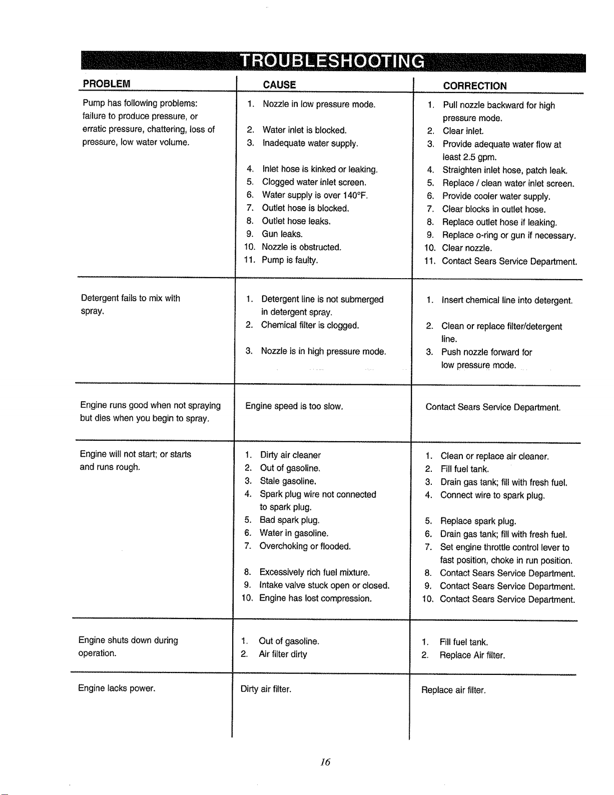
PROBLEM
Pump has following problems:
failure to produce pressure, or
erratic pressure, chattering, toss of
pressure, low water volume.
Detergentfailsto mixwith
spray,
1.
CAUSE
Nozzlein low pressuremode.
2. Water inlet isblocked.
3. Inadequate water supply.
4, Inlet hose is kinked or leaking.
5, Clogged water inlet screen,
6. Water supply is over 140°F.
7. Outlet hose is blocked,
8. Outlet hose leaks.
9. Gun leaks.
10. Nozzle is obstructed.
11. Pump is faulty,
1. Detergent line is not submerged
in detergent spray.
2. Chemical filter is clogged.
3. Nozzle is in high pressure mode.
CORRECTION
1. Pull nozzle backward for high
pressure mode.
2. Clear inlet.
3. Provide adequate water flow at
least 2.5 gpm,
4, Straighten inlet hose, patch leak.
5. Replace / clean water inlet screen.
6. Provide cooler water supply.
7. Clear blocks in outlet hose.
8. Replace outlet hose if leaking.
9. Replace o-ring or gun if necessary,
10. Clear nozzle.
11, Contact Sears Service Department,
1. Insert chemical line into detergent.
2. Clean or replace filter/detergent
line.
3. Push nozzle forward for
Engine runs good when not spraying
but dies when you begin to spray,
Enginewill not start;or starts
and runsrough.
Engine speed istoo slow.
1. Dirty air cleaner
2. Out of gasoline.
3. Stale gasoline,
low pressure mode,
Contact Sears Service Department.
1. Cleanor replaceair cleaner.
2. Fillfuel tank.
3. Draingastank;fill withfreshfuel.
4. Spark plug wire not connected
to spark plug,
5. Bad spark plug.
6. Water in gasoline.
7. Overchoking or flooded,
8. Excessively rich fuel mixture.
9. intake valve stuck open or closed.
10, Engine has lost compression,
Engine shuts down during
operation.
Engine lacks power.
1. Out of gasoline.
2. Air filter dirty
Dirty air filter.
4. Connect wire to spark plug.
5, Replace spark ptug.
6, Drain gas tank; fill withfresh fuel.
7. Set engine throttle control lever to
fast position, choke in run position.
8. Contact Sears Service Department.
9. Contact Sears Service Department.
10. Contact Sears Service Department.
1. Fill fuel tank.
2. Replace Air filter.
Replace air filter.
]6

17
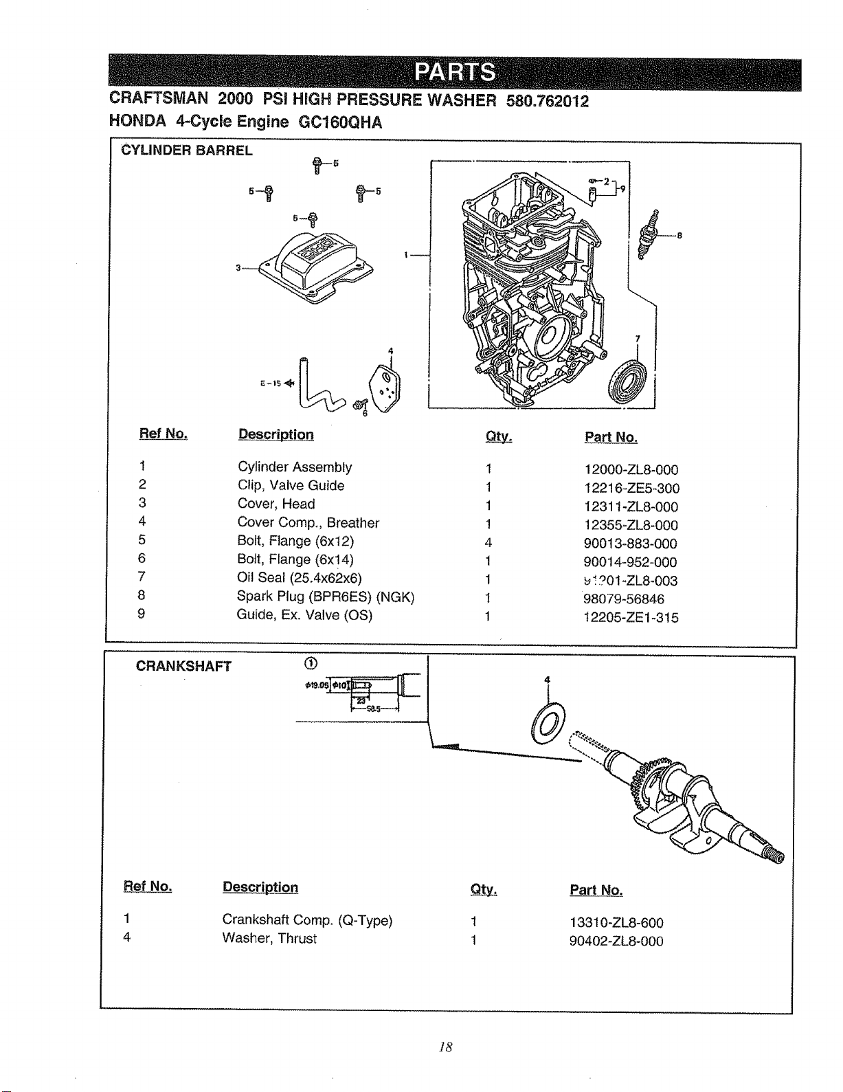
CRAFTSMAN 2000 PSi HIGH PRESSURE WASHER 580.762012
HONDA 4-Cycle Engine GC160QHA
CYLINDER BARREL
Ref No,
4
Part No.
i
1
2
3
4
5
6
7
8
9
Cylinder Assembly
Clip, Valve Guide
Cover, Head
Cover Comp., Breather
Bolt, Flange (6x12)
Bolt, Flange (6x!4)
OIl Seal (25.4x62x6)
Spark Plug (BPR6ES) (NGK)
Guide, Ex. Valve (OS)
1
1
1
!
4
1
1
1
1
12000-ZL8-000
12216-ZE5-300
1231t-ZL8_000
12355-ZL8-000
90013-883-000
90014-952-000
_!90!-ZL8-003
98079-56846
12205-ZE1-315
CRANKSHAFT
Ref No.
1
4
Crankshaft Comp. (Q-Type)
Washer, Thrust
1
1
Part No.
13310-ZL8-600
90402-ZL8-000
18
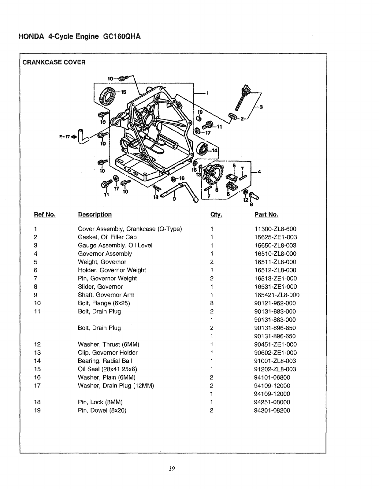
HONDA 4-Cycle Engine GC160QHA
CRANKCASE COVER
E-I?
[
t
i0
.3
Ref No.
1
2
3
4
5
6
7
8
9
t0
11
12
13
14
t5
16
17
18
19
1 18'
Description
Cover Assembly, Crankcase (Q-Type)
Gasket, Oil Filler Cap
Gauge Assembly, Oil Level
Governor Assembly
Weight, Governor
Holder, Governor Weight
Pin, Governor Weight
Slider, Governor
Shaft, Governor Arm
Bolt, Flange (6x25)
Bolt, Drain Plug
Bolt, Drain Plug
Washer, Thrust (6MM)
Clip, Governor Holder
Bearing, Radial Ball
Oil Seal (28x41.25x6)
Washer, Plain (6MM)
Washer, Drain Plug (12MM)
Pin, Lock (8MM)
Pin, Dowel (8x20)
1
1
1
1
2
1
2
1
i
8
2
1
2
1
1
1
1
1
2
2
1
1
2
8
P_artNo.
11300-ZL8-600
15625-ZE1-003
15650+ZL8-003
16510-ZL8-000
16511+ZL8-000
16512-ZL8+000
16513-ZE1-000
16531-ZE1-000
16542t-ZL8-000
90121-952-000
90131-883-000
90131-883-000
90131-896-650
90131-896-650
90451-ZE1-000
90602-ZE1-000
91001-ZL8-003
91202-ZL8-003
94101-06800
94109-12000
941O9-12000
94251-08000
94301-08200
]9
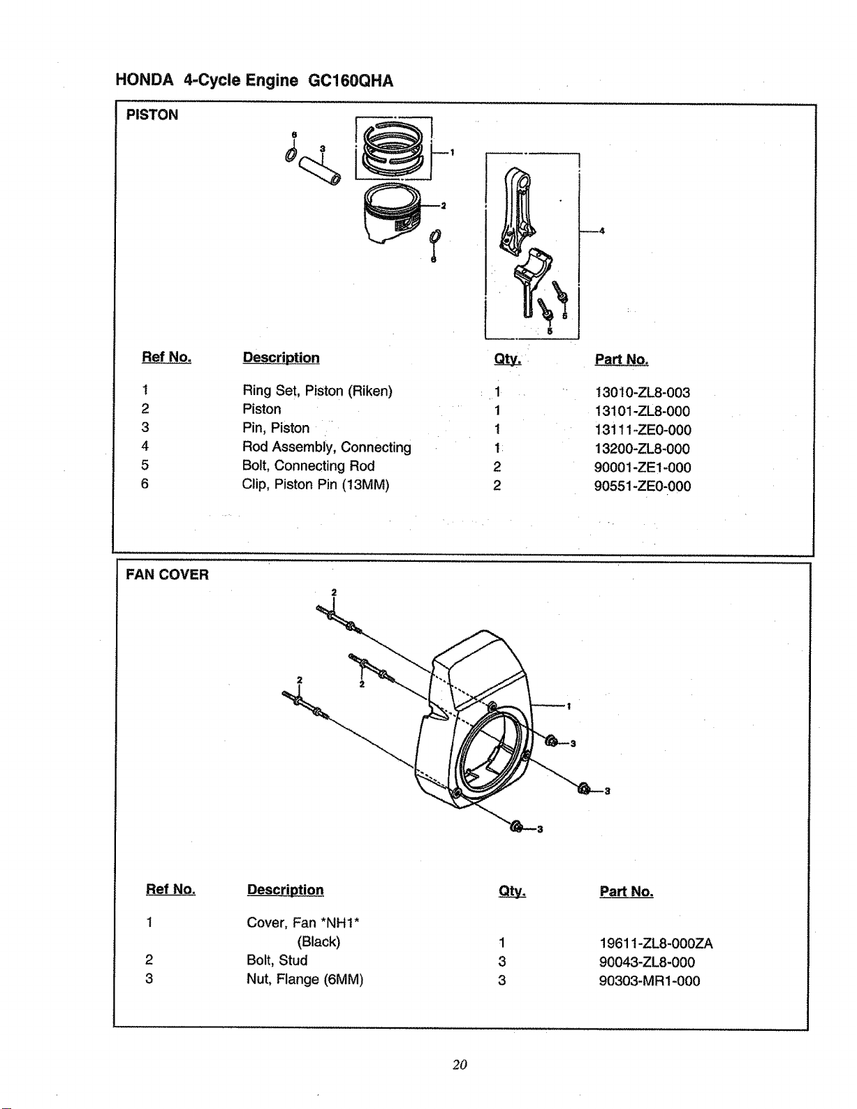
HONDA
PISTON
4-Cycle Engine GC160QHA
° r
_4
Ref No.
1
2
3
4
5
6
Description
Ring Set, Piston (Riken)
Piston
Pin, Piston
Rod Assembiy, Connecting
Bolt, Connecting Rod
Clip, Piston Pin (t3MM)
1
1
!
1
2
2
PaN No.
13010-ZL8-003
13101 -ZL8-O00
13111 -ZEO-O00
13200-ZL8-000
90001-ZE1-000
90551-ZE0-000
FAN COVER
Ref No.
t
2
3
Description
Cover, Fan *NHt*
(Black)
Bolt, Stud
Nut, Flange (6MM)
1
3
3
PaN No.
19611-ZL8-000ZA
90043-ZL8-000
90303-MR1-000
2O
HONDA
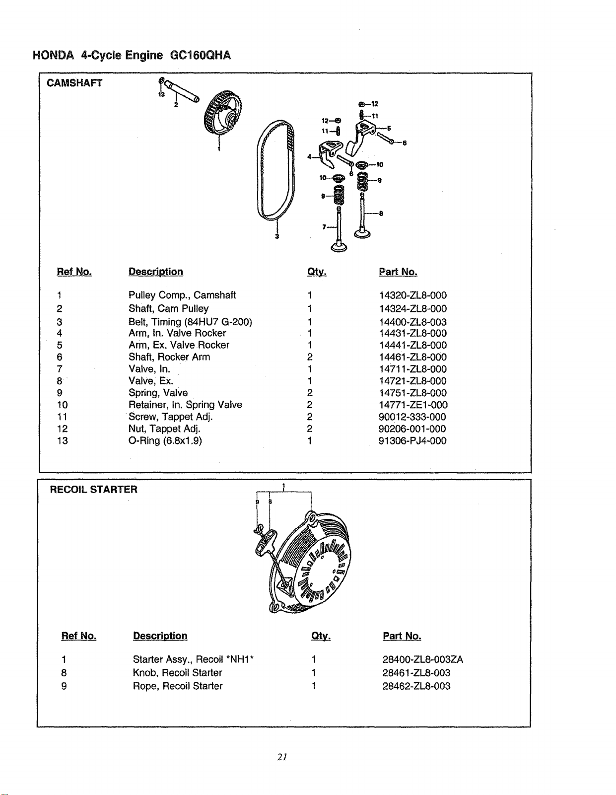
CAMSHAFT
4-Cycle Engine GC160QHA
t!_--12
1
2
3
4
5
6
7
8
9
!0
11
12
13
Pulley Comp., Camshaft
Shaft, Cam Pulley
Belt, Timing (84HU7 G-200)
Arm, In. Valve Rocker
Arm, Ex. Valve Rocker
Shaft, Rocker Arm
Valve, In.
Valve, Ex.
Spring, Valve
Retainer, In. Spring Valve
Screw, Tappet Adj.
Nut, Tappet Adj.
O-Ring (6.8xl .9)
Part No.
1
1
1
1
t
2
1
1
2
2
2
2
1
14320-ZL8-000
14324-ZL8-000
14400-ZL8-003
14431-ZL8-000
14441-ZL8-000
14461-ZL8-000
14711 -ZL8-000
!472 i-ZL8-000
14751 -ZL8-000
14771 -ZE1-000
90012-333-000
90206-001-000
91306-PJ4-000
RECOIL STARTER
1
8
9
Starter Assy., Recoil *NH1 *
Knob, Recoil Starter
Rope, Recoil Starter
1
1
1
Part No.
28400-ZL8-003ZA
28461-ZL8-003
28462-ZL8-003
2]
HONDA 4-Cycle Engine GC160QHA
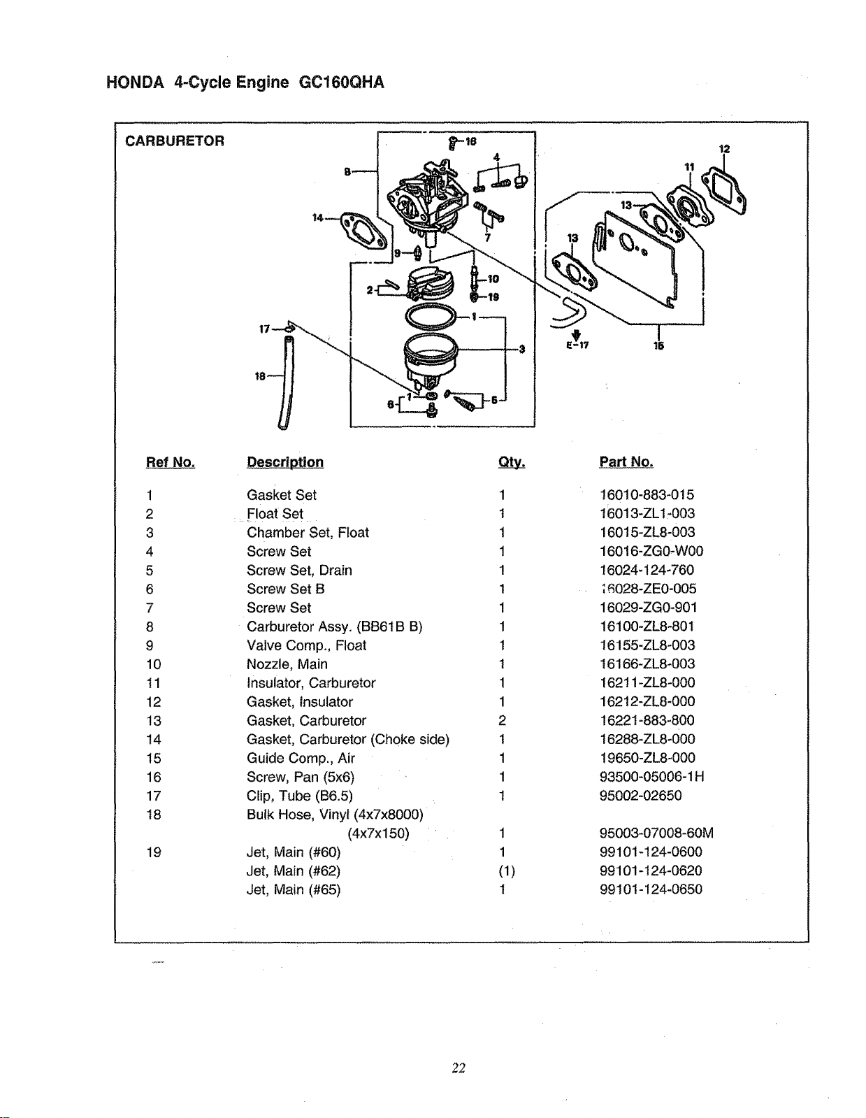
CARBURETOR
4
12
11
1
2
3
4
5
6
7
8
9
10
tl
12
!3
14
15
16
17
18
19
Description
Gasket Set
Float Set
Chamber Set, Float
Screw Set
Screw Set, Drain
Screw Set B
Screw Set
Carburetor Assy. (BB61B B)
Valve Comp., Float
Nozzle, Main
Insulator, Carburetor
Gasket, Insulator
Gasket, Carburetor
Gasket, Carburetor (Choke side)
Guide Comp., Air
Screw, Pan (5x6)
Clip, Tube (B6.5)
Bulk Hose, Vinyl (4x7x8000)
(4x7x150)
Jet, Main (#60)
Jet, Main (#62)
Jet, Main (#65)
1
I
1
1
!
t
1
1
1
1
1
1
2
t
1
1
1
1
1
(1)
1
I
15
Part No.
16010-883-015
16013-ZL1-003
16015-ZL8-003
16016-ZG0-W00
16024-124-760
;_028-ZE0-005
16029-ZG0-901
16100-ZL8-801
16155-ZL8-003
16t66-ZL8-003
16211-ZL8-000
16212-ZL8-000
16221-883-800
16288-ZL8-000
19650-ZL8-000
93500-05006-1H
95O02-02650
95003-07008-60M
99101-124-0600
99101-124-0620
99101-124-0650
22
HONDA 4-Cycle Engine GC160QHA
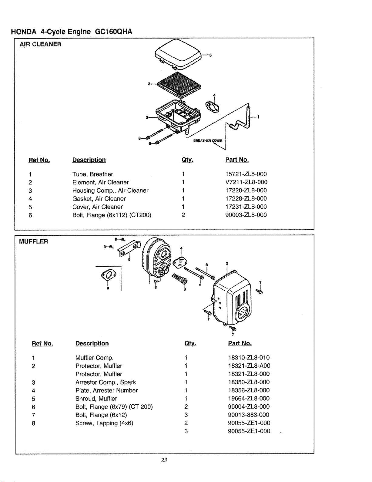
AIR CLEANER
4
Ref No.
1
2
3
4
5
6
Tube, Breather
Element, Air Cleaner
Housing Comp., Air Cleaner
Gasket, Air Cleaner
Cover, Air Cleaner
Bolt, Flange (6xl 12) (CT200)
et_ty
!
!
1
1
1
2
Part No.
15721-ZL8-000
V7211-ZL8-000
17220-ZL8-000
17228-ZL8-000
17231-ZL8-000
90003-ZL8-000
MUFFLER
7
Ref No,
!
2
3
4
5
6
7
8
Description
Muffler Comp.
Protector, Muffler
Protector, Muffler
Arrestor Comp., Spark
Plate, Arrester Number
Shroud, Muffler
Bolt, Flange (6x79) (CT 200)
Bolt, Flange (6xt2)
Screw, Tapping (4x6)
1
1
1
1
1
1
2
3
2
3
Part No.
18310-ZL8-010
18321 -ZL8-A00
18321 -ZL8-000
18350-ZL8-000
18356-ZL8-000
19664-ZL8-000
90004-ZL8-000
90013-883-000
90055-ZE1-000
90055-ZE1-000
23
HONDA 4-Cycle Engine GC160QHA
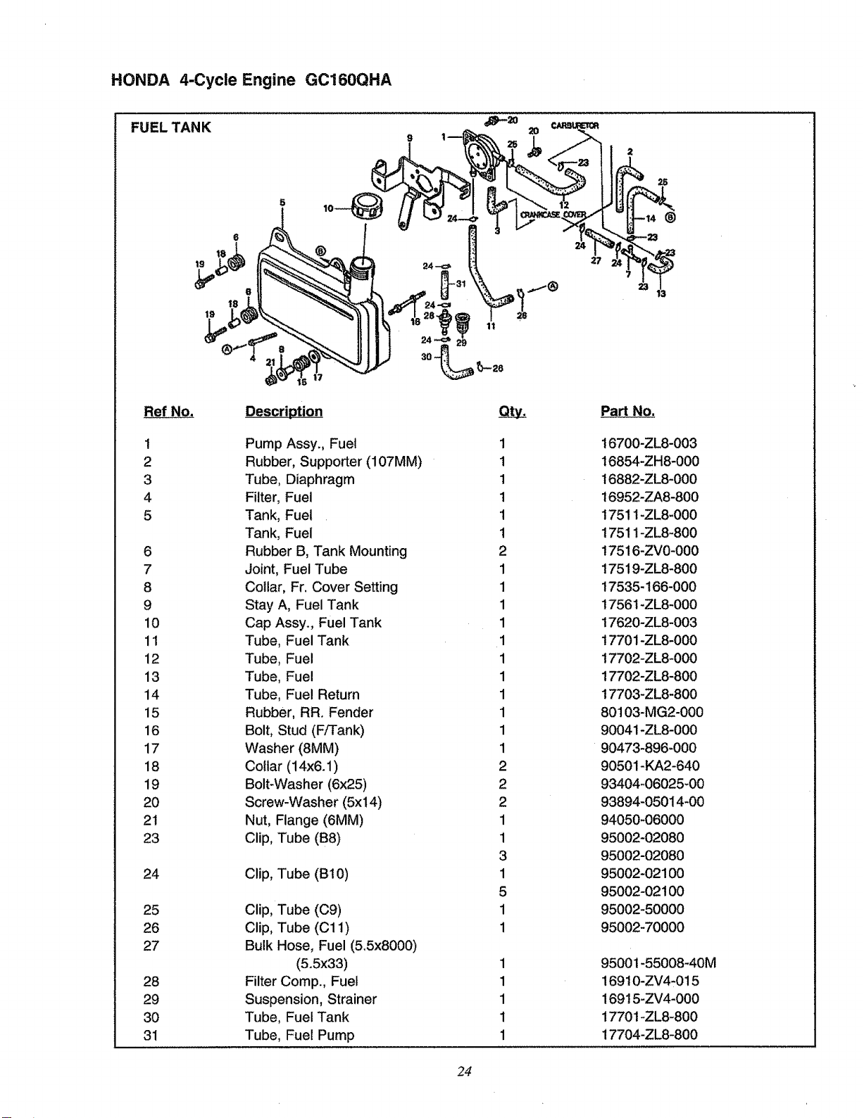
FUEL TANK
Ref No.
1
2
3
4
5
6
7
8
9
10
11
12
13
14
15
16
17
18
19
20
21
23
24
25
26
27
28
29
30
31
17
Description
Pump Assy., Fuel
Rubber, Supporter (107MM)
Tube, Diaphragm
Filter, Fuel
Tank, Fuel
Tank, Fuel
Rubber B, Tank Mounting
Joint, Fuel Tube
Collar, Fr. Cover Setting
Stay A, Fuel Tank
Cap Assy., Fuel Tank
Tube, Fuel Tank
Tube, Fuel
Tube, Fuel
Tube, Fue! Return
Rubber, RR. Fender
Bolt, Stud (F/Tank)
Washer (8MM)
Collar (14x6.1 )
Bolt-Washer (6x25)
Screw-Washer (5x14)
Nut, Flange (6MM)
Clip, Tube (B8)
Clip, Tube (B!0)
Clip, Tube (C9)
Clip, Tube (C11)
Bulk Hose, Fuel (5.5x8000)
(5.5x33)
Filter Comp., Fuel
Suspension, Strainer
Tube, Fuel Tank
Tube, Fuel Pump
1
1
1
1
1
1
2
1
1
1
1
1
1
1
1
1
1
1
2
2
2
1
1
3
1
5
1
1
1
1
1
1
1
®
Part No.
t6700-ZL8-003
16854-ZH8-000
16882-ZL8-000
16952-ZA8-800
17511-ZL8-000
17511-ZL8-800
17516-ZV0-000
17519-ZL8-800
17535-166-000
t7561-ZL8-000
17620-ZL8-003
t7701-ZL8-000
17702-ZL8-000
17702-ZL8-800
17703-ZL8-800
80103-MG2-000
90041-ZL8-000
90473-896-000
90501-KA2-640
93404-06025-00
93894-05014-00
94050-O6000
95002-02080
95002-02080
95002-02100
95002-02100
95002-50000
95002-70000
95001-55008-40M
16910-ZV4-015
169!5-ZV4-000
17701-ZL8-800
17704-ZL8-800
24
HONDA 4-Cycle Engine GC160QHA
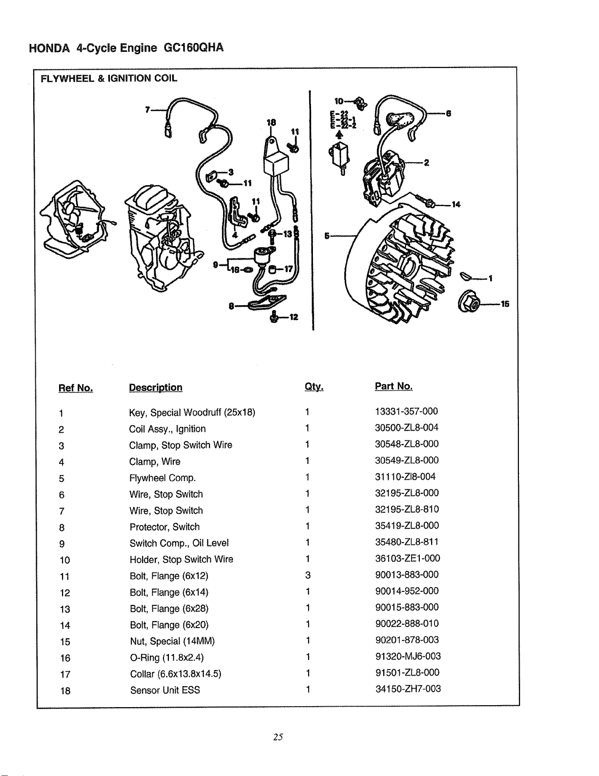
FLYWHEEL & IGNITION COIL
Ref No. Description
t
2
3
4
5
6
7
8
9
10
11
12
13
14
15
16
17
18
Key, Special Woodruff (25xl 8)
Coil Assy., Ignition
Clamp, Stop Switch Wire
Clamp, Wire
Flywheel Comp.
Wire, Stop Switch
Wire, Stop Switch
Protector, Switch
Switch Comp., Oil Level
Holder, Stop Switch Wire
Bolt, Flange (6xt2)
Bolt, Flange (6x14)
Bolt, Flange (6x28)
Bolt, Flange (6x20)
Nut, Special (14MM)
O-Ring (11.8x2.4)
Collar (6.6x13.8x14.5)
Sensor Unit ESS
1
1
1
1
1
I
1
1
1
1
3
1
1
1
1
1
1
Part No.
13331-357-000
30500-ZL8-004
30548-ZL8-000
30549-ZL8-000
3t 110-ZI8-004
32195-ZL8-000
32195-ZL8-810
354!9-ZL8-000
35480-ZL8-811
36103-ZE1-000
90013-883-000
90014-952-000
90015-883-000
90022-888-010
90201-878-003
91320-MJ6-003
9150t-ZL8-000
34! 50-ZH7-003
25
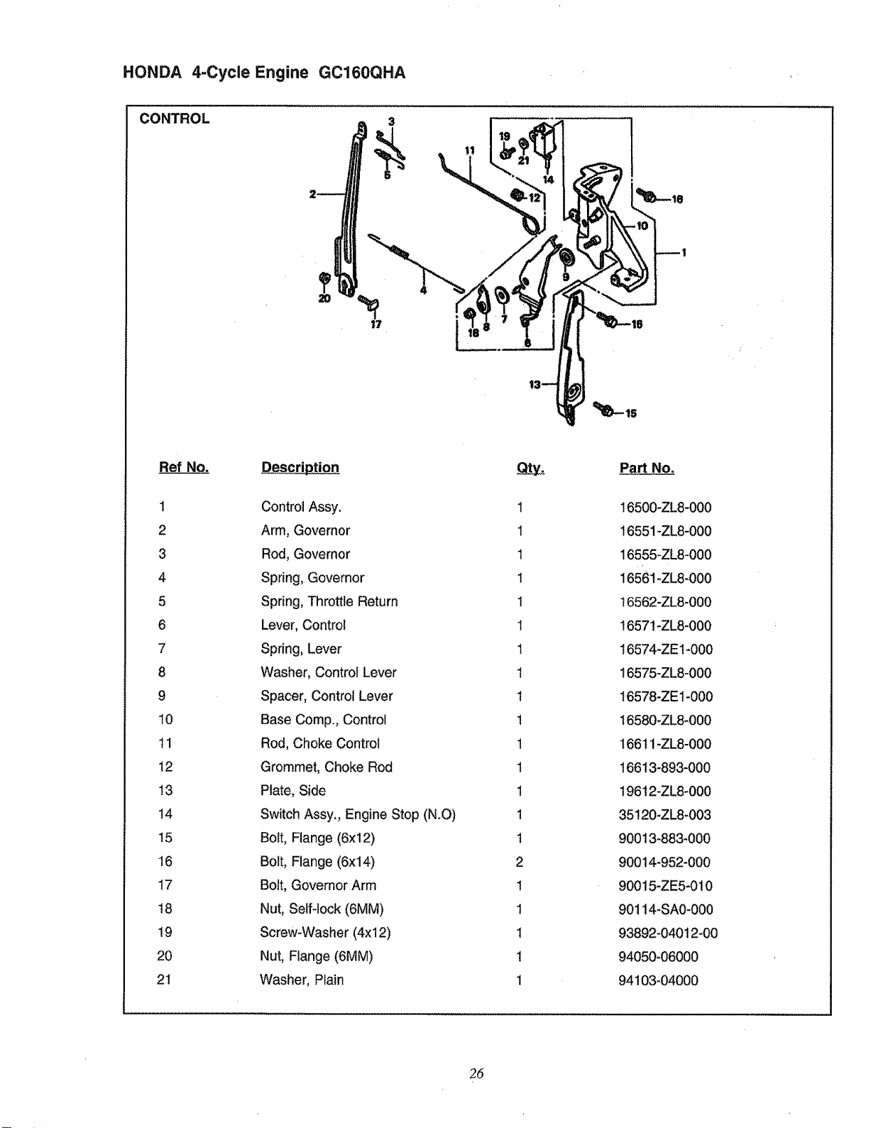
HONDA 4-Cycle Engine GC160QHA
CONTROL
Ref No.
1
2
3
4
5
6
7
8
9
10
tl
12
13
14
15
16
17
!8
19
20
21
Description
Control Assy.
Arm, Governor
Rod, Governor
Spring, Governor
Spring, Throttle Return
Lever, Control
Spring, Lever
Washer, Control Lever
Spacer, Control Lever
Base Comp. Control
Rod, Choke Control
Grommet, Choke Rod
Plate, Side
Switch Assy. Engine Stop (N.O)
Bolt, Flange (6x12)
Bolt, Flange (6x14)
Bolt, Governor Arm
Nut, Self-lock (6MM)
Screw*Washer (4xl 2)
Nut, Flange (6MM)
Washer, Piain
1
1
1
1
1
1
1
1
I
!
1
!
1
1
1
2
1
1
1
1
1
Part No.
16500-ZL8-000
16551-ZL8-000
16555-ZL8-000
16561-ZL8-000
t6562-ZL8-000
1657!-ZL8-000
16574-ZE1-000
16575-ZL8-000
t6578-ZE1-000
16580-ZL8-000
166tl-ZL8-000
16613-893-000
19612-ZL8-000
35!20-ZL8-003
90013-883-000
90014-952-000
90015-ZE5-010
90114-SA0-000
93892-04012-00
94050-06000
94103-04000
26
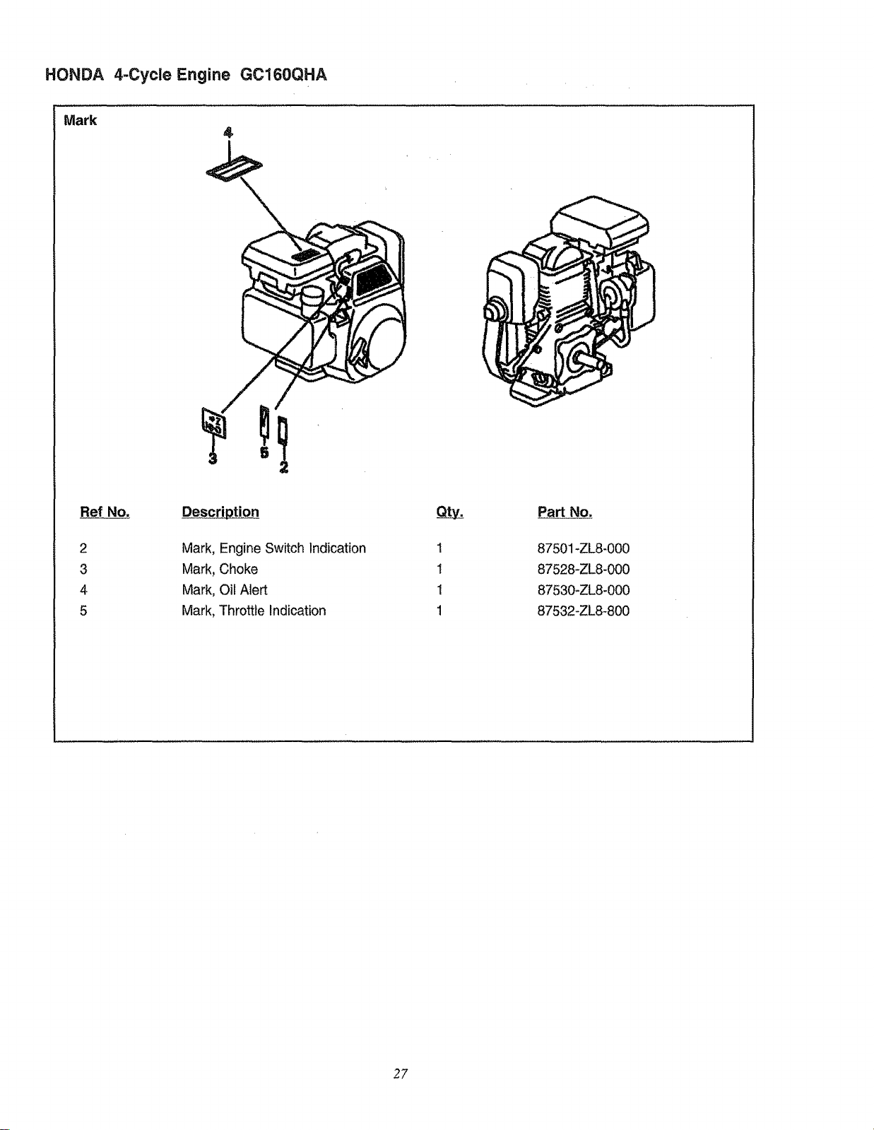
HONDA 4-Cycle Engine GC160QHA
Mark
Ref No.
2
3
4
5
Description
Mark, Engine Switch Indication
Mark, Choke
Mark, Oil Nert
Mark, Throttle Indication
1
1
1
1
87501 -ZLS-O00
87528-ZL8-000
87530+ZL8-000
87532-ZL8-800
2?
CRAFTSMAN 2000 PSI HiGH PRESSURE WASHER 580.762012
/t SEAL
_8
19
_,g--
2
3
4
3
3O
44
4O
44
29
4:=
43
- 5O
-51
- 52
lf_, °o°1
_oOO/
o_ooool-
Jo%!
5_
28
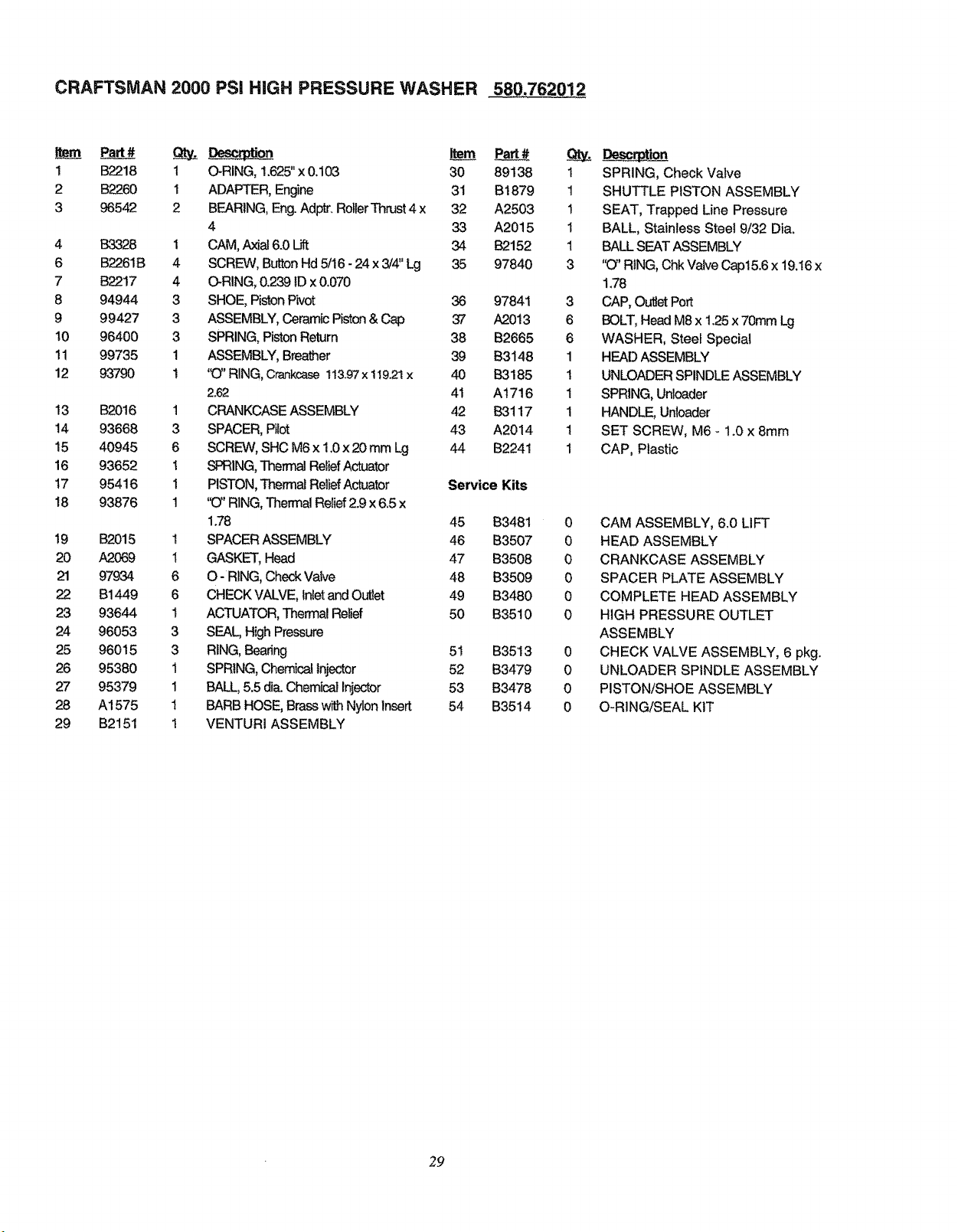
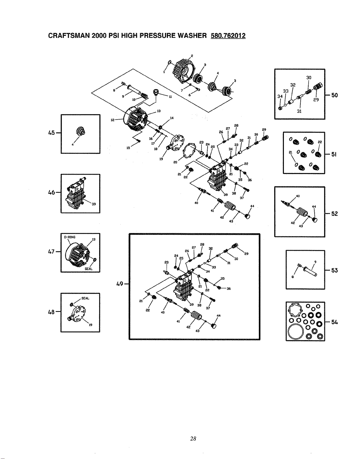
CRAFTSMAN 2000 PSI HiGH PRESSURE WASHER 580.762012
Item Part# Q_.
1 B2218 !
2 B2260 1
3 96542 2
4 B3328 1
6 B2261B 4
7 B2217 4
8 94944 3
9 99427 3
10 96400 3
11 99735 1
12 93790 t
13 B2016
14 93668
15 40945
16 93652
17 95416
18 93876
19
20
21
22
23
24
25
26
27
28
29
B2015
A2069
97934
B1449
93644
96053
96015
95380
95379
A1575
B2151
1
3
6
1
i
1
1
1
6
6
1
3
3
1
1
1
1
O-RING, 1.625"x 0.1(_3
ADAPTER, Engine
BEARING, Eng.Adptr. RollerThrust4 x
4
CAM, Axial6.0 Lift
SCREW, Button Hd 5/16 -24 x 3/4" Lg
O-RING, 0.239 tD x 0.070
SHOE, Piston P_ot
ASSEMBLY, Ceramic Piston& Cap
SPRING, Piston Return
ASSEMBLY, Breather
"(3"RING, Crankcase1t&97 x 11921x
2.62
CRANKCASE ASSEMBLY
SPACER, Pilot
SCREW, SHC M6 x 1.0 x 20 mm Lg
SPRING,Thermal ReliefActuator
PISTON, Thermal ReliefActuator
%)"RING, Thermal Relief2.9 x 6.5 x
1.78
SPACER ASSEMBLY
GASKET, Head
O-RING, Check Valve
CHECK VALVE, Inletand O_et
ACTUATOR, Then_nalRelief
SEAL, High Pressure
RING, Bearing
SPRING, Chemical Injector
BALL, 5.5 dia.Chemical Injector
BARB HOSE, Brassw_h Nylon Insert
VENTURI ASSEMBLY
30 89138 1
31 B1879 1
32 A2503 1
33 A2015 1
34 B2152 1
35 97840 3
36 97841
37 A2013
38 B2665
39 B3148
40 B3185
41 A1716
42 B3117
43 A2014
44 B2241
Service Kits
45 B3481
46 B3507
47 B3508
48 B3509
49 B3480
50 B3510
51 B3513
52 B3479
53 B3478
54 B3514
3
6
6
1
1
1
1
1
1
_______j_ion
SPRING, Check Valve
SHUTTLE PISTON ASSEMBLY
SEAT, Trapped Line Pressure
BALL, Stainless Steel 9/32 Dia.
BALL SEAT ASSEMBLY
'O" RING, ChkValve Cap15.6 x 19.16x
1.78
CAP, Outlet Port
BOLT, Head M8 x 1.25x 70mm Lg
WASHER, Steel Special
HEAD ASSEMBLY
UNLOADER SPINDLE ASSEMBLY
SPRING, Unloader
HANDLE, Unloader
SET SCREW, M6 - 1.0 x 8mm
CAP, Plastic
0 CAM ASSEMBLY, 6.0 LIFT
0 HEAD ASSEMBLY
0 CRANKCASE ASSEMBLY
0 SPACER PLATE ASSEMBLY
0 COMPLETE HEAD ASSEMBLY
0 HIGH PRESSURE OUTLET
ASSEMBLY
0 CHECK VALVE ASSEMBLY, 6 pkg.
0 UNLOADER SPINDLE ASSEMBLY
0 PISTON/SHOE ASSEMBLY
0 O-RING/SEAL KIT
29
CRAFTSMAN 2000 PSI HiGH PRESSURE WASHER 580.762012
19
15 12_
12
17
17
t3
14
I0
16
5
45
30
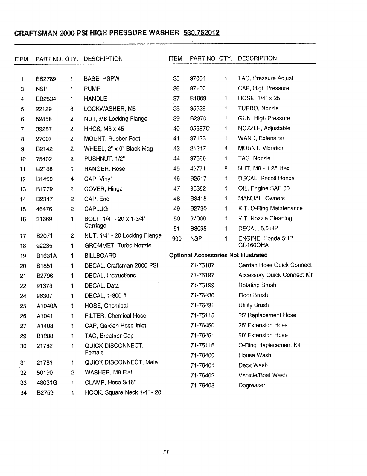
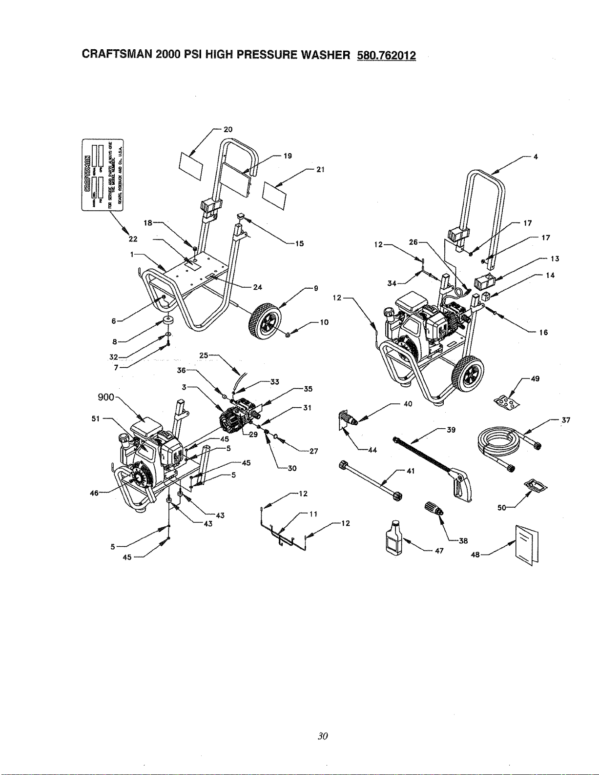
CRAFTSMAN 2000 PSI HiGH PRESSURE WASHER 580.762012
ITEM PART NO. QTY. DESCRIPTION
ITEM PART NO. QTY. DESCRIPTION
t EB2789 1 BASEi HSPW
3 NSP 1 PUMP
4 EB2534 1 HANDLE
5 22129 8 LOCKWASHER, M8
6 52858 2 NUT, M8 Locking Flange
7 39287 : 2 HHCS, M8 x 45
8 27007 2 MOUNT, Rubber Foot
9 B2142 2 WHEEL, 2" x 9" Black Mag
10 75402 2 PUSHNUT, 1/2"
11 B2168 1 HANGER, Hose
12 B1460 4 CAP, Vinyl
13 B1779 2 COVER, Hinge
14 B2347 2 CAP, End
15 46476 2 CAPLUG
16 31669 1 BOLT, 1/4" - 20 x I-3/4"
Carriage
!7 B2071 2 NUT, 1/4" - 20 Locking Flange
18 92235 1 GROMMET, Turbo Nozzle
19 B1631A I BILLBOARD
20 B1851 1 DECAL, Craftsman 2000 PSI
21 B2796 1 DECAL, Instructions
22 91373 1 DECAL, Data
24 96307 1 DECAL, 1-800 #
25 AI040A 1 HOSE, Chemical
26 A1041 1 FILTER, Chemical Hose
27 A1408 t CAP, Garden Hose Inlet
29 B1288 1 TAG, Breather Cap
30 21782 1 QUICK DISCONNECT,
Female
31 21781 1 QUICK DISCONNECT, Male
32 50190 2 WASHER, M8 Flat
33 48031G 1 CLAMP, Hose 3/16"
34 B2759 1 HOOK, Square Neck 1/4" - 20
35 97054 1 TAG, Pressure Adjust
36 97100 1 CAP, High Pressure
37 B1969 1 HOSE, 1/4" x 25'
38 95529 1 TURBO, Nozzle
39 B2370 1 GUN, High Pressure
40 95587C 1 NOZZLE, Adjustable
41 97123 ! WAND, Extension
43 21217 4 MOUNT, Vibration
44 97566 t TAG, Nozzle
45 45771 8 NUT, M8 - 1.25 Hex
46 B2517 1 DECAL, Recoil Honda
47 96382 1 OIL, Engine SAE 30
48 B34t8 1 MANUAL, Owners
49 B2730 1 KIT, O-Ring Maintenance
50 97009 1 KIT, Nozzle Cleaning
51 B3095 1 DECAL, 5.0 HP
900 NSP 1 ENGINE, Honda 5HP
GC160QHA
Optional Accessories Not Illustrated
71-75187 Garden Hose Quick Connect
71-75197 Accessory Quick Connect Kit
7! -75199 Rotating Brush
71-76430 Floor Bru._h
71-76431 Utility Brush
71-75115 25' Replacement Hose
71-76450 25' Extension Hose
71-76451 50' Extension Hose
71-75116 O-Ring Replacement Kit
7I-76400 House Wash
71-76401 Deck Wash
71-76402 Vehicle/Boat Wash
71-76403 Degreaser
3]
Emission Control System Warranty
Your new Honda Power Equipment engine complies with both the U.S. EPA and State of California emission regulations. American Honda
provides the same emission warranty coverage for engines sold in all 50 states.
YOUR WARRANTY RIGHTS AND OBLIGATIONS:
California
The California Air Resources Board and American Honda Motor Co., Inc. are leased to explain the emission control system warranty on your
Honda Power Equipment engine. In California, new utility and lawn and garden equipment must be designed, built and equipped to meet the
State's stringent anti-smog standards.
Other States
In other areas of the United States your engine must be designed, built and equipped to meet the U.S. EPA Phase I Emission standard for
spark ignited engines at or below t9 kilowatts.
All States
American Honda Motor Co., Inc. must warrant the emission control system on your power equipment engine for the period of time listed
below provided there has been no abuse, neglect or improper maintenance of your power equipment engine. Where a warrantable condition
exists, American Honda Motor Co,, Inc. will repair your power equipment engine at no cost to you including diagnosis, parts and labor.
Your emission control system may include such parts as the carburetor or fuel injection system, the ignition system and catalytic converter.
Also included may be hoses, connectors and other emission*related assemblies.
MANUFACTURER'S WARRANTY COVERAGE:
The t 995 and later power equipment are warranted for two years. If any emission-related part on your engine is defective, the part will be
repaired or replaced by American Honda Motor Co,, Inc.
OWNER'S WARRANTY RESPONSIBILITY:
As the power equipment engine owner, you are responsible for the performance of the required maintenance listed in your owner's manual.
American Honda Motor Co, Inc. recommends that you retain al! receipts covering maintenance on your power equipment engine, but
American Honda Motor Co., Inc. cannot deny warranty coverage solely for the lack of receipts or for your failure to ensure the performance
of all scheduled maintenance.
As the power equipment engine owner you should however be aware that American Honda Motor Co., Inc. may deny you warranty coverage
if you power equipment engine or a part has failed due to abuse, neglect, improper maintenance, or unapproved modifications.
You are responsible for resenting your power equipment engine to a Honda Power Equipment dealer as soon as a problem exists. The war-
ranty repairs should be completed in a reasonable amount of time, not to exceed 30 days.
If you have any questions regarding your warranty rights and responsibilities, you should contact:
American Honda Motor Co., Inc.
Power Equipment Customer Relations
4475 River Green Parkway
Duluth, Georgia 30136-2565
Telephone: (770) 497-6400
WARRANTY COVERAGE:
Honda power equipment engine manufactured after January 1, 1995 and sold in the State of California, and U.S. EPA certified engines man-
ufactured on or after September 1, 1996 and sold in all of the United States, are covered by this warranty for a period of two years from the
date of delivery to the original retail purchaser. This warranty is transferable to each subsequent purchase for the duration of the warranty
period.
Warranty repairs will be made without charge for diagnosis, parts or labor. All defective parts replaced under this warranty become the prop-
arty of American Honda Motor Co., inc. A list of warranted parts is on the reverse side of this warranty statement. Normal maintenance
items, such as spark plugs and filters, that are on the warranted parts list are warranted up to their required replacement interval only.
American Honda Motor Co., Inc. is also liable fro damages to other engine components caused by a failure of any warranted part during the
warranty period.
Only Honda approved replacement parts may be used in the performance of any warranty repairs and must be provided without charge to
the owner. The use of replacement parts not equivalent to the original parts may impair the effectiveness of your engine emission control
system, if such a replacement art is used in the repair or maintenance of your engine, and an authorized Honda dealer determines it is
defective or causes a failure of a warranted part, your claim for repair of your engine may be denied. If the part in question is not related to
the reason your engine requires repair, your claim will not be denied.
TO OBTAIN WARRANTY SERVICE: (see page 33)
EXCLUSIONS: (see page 33)
DISCLAIMER OF CONSEQUENTIAL DAMAGE AND LIMITATION OF IMPLIED WARRANTIES: (see page 33)
32
Emission Control System Warranty
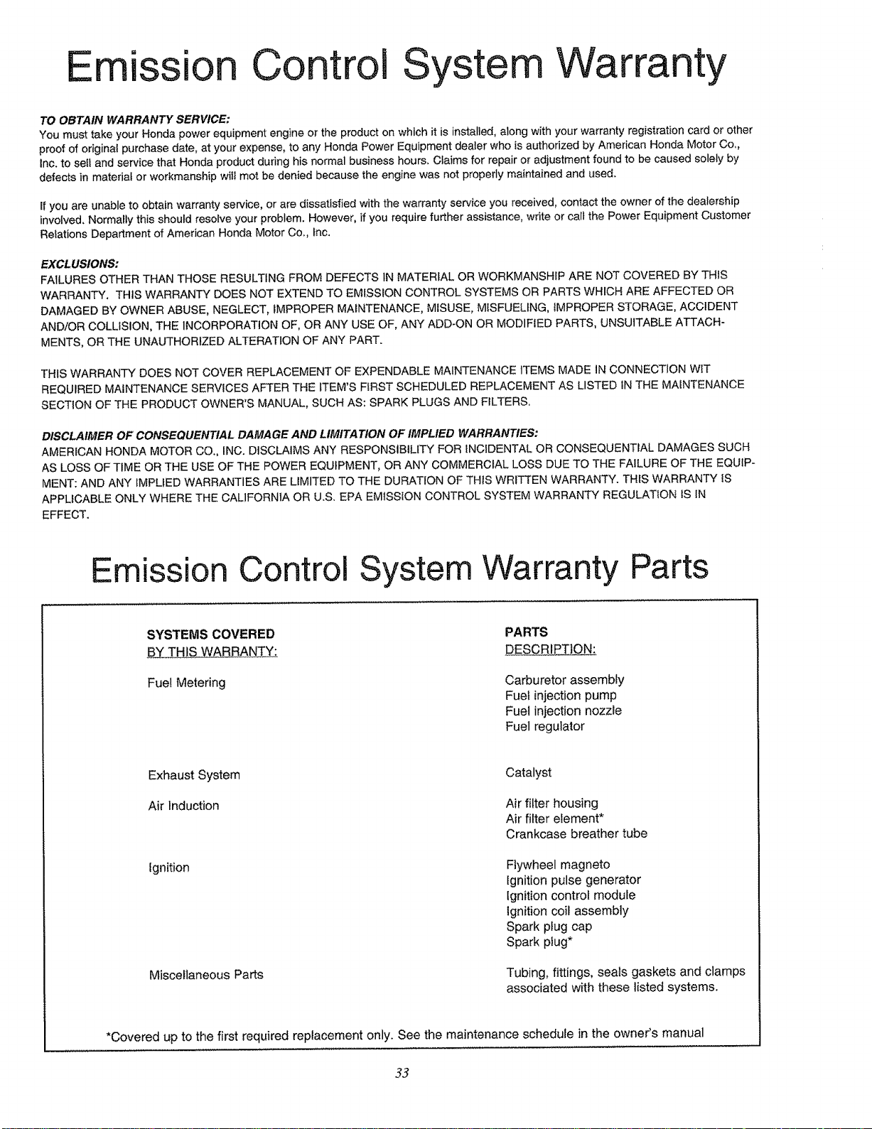
TO OBTAIN WARRANTY SERVICE:
You must take your Honda power equipment engine or the product on which it is installed, along with your warranty registration card or other
proof of originai purchase date, at your expense, to any Honda Power Equipment dealer who is authorized by American Honda Motor Co,,
Inc. to set! and service that Honda product during his normal business hours. Claims for repair or adjustment found to be caused solely by
defects in material or workmanship wit1 mot be denied because the engine was not properly maintained and used.
If you are unable to obtain warranty service, or are dissatisfied with the warranty service you received, contact the owner of the dealership
involved. Normally this should resolve your problem. However, if you require further assistance, write or call the Power Equipment Customer
Relations Department of American Honda Motor Co,, Inc.
EXCLUSIONS:
FAILURES OTHER THAN THOSE RESULTING FROM DEFECTS IN MATERIAL OR WORKMANSHIP ARE NOT COVERED BY THIS
WARRANTY. THIS WARRANTY DOES NOT EXTEND TO EMISSION CONTROL SYSTEMS OR PARTS WHICH ARE AFFECTED OR
DAMAGED BY OWNER ABUSE, NEGLECT, IMPROPER MAINTENANCE, MISUSE, MISFUELING, IMPROPER STORAGE, ACCIDENT
AND/OR COLLISION, THE INCORPORATION OF, OR ANY USE OF, ANY ADD-ON OR MODIFIED PARTS, UNSUITABLE ATTACH-
MENTS, OR THE UNAUTHORIZED ALTERATION OF ANY PART.
THtS WARRANTY DOES NOT COVER REPLACEMENT OF EXPENDABLE MAINTENANCE ITEMS MADE IN CONNECTION WIT
REQUIRED MAINTENANCE SERVICES AFTER THE ITEM'S FIRST SCHEDULED REPLACEMENT AS LISTED IN THE MAINTENANCE
SECTION OF THE PRODUCT OWNER'S MANUAL, SUCH AS: SPARK PLUGS AND FILTERS.
DISCLAIMER OF CONSEQUENTIAL DAMAGE AND LIMITATION OF IMPLIED WARRANTIES:
AMERICAN HONDA MOTOR CO., INC. DISCLAIMS ANY RESPONSIBILITY FOR INCIDENTAL OR CONSEQUENTIAL DAMAGES SUCH
AS LOSS OF TIME OR THE USE OF THE POWER EQUIPMENT, OR ANY COMMERCIAL LOSS DUE TO THE FAILURE OF THE EQUIP-
MENT: AND ANY IMPLIED WARRANTIES ARE LIMITED TO THE DURATION OF THIS WRITTEN WARRANTY. THIS WARRANTY iS
APPLICABLE ONLY WHERE THE CALIFORNIA OR U.S. EPA EMISSION CONTROL SYSTEM WARRANTY REGULATION IS IN
EFFECT.
Emission Control System Warranty Parts
SYSTEMS COVERED
BY THIS WARRANTY:
Fue! Metering
PARTS
DESCRIPTION:
Carburetor assembly
Fuel injection pump
Fuet injection nozzle
Fuel regulator
Exhaust System
Air Induction
Ignition
Miscellaneous Parts
Catalyst
Air filter housing
Air filter element*
Crankcase breather tube
Flywheel magneto
Ignition pulse generator
Ignition control module
Ignition coil assembly
Spark plug cap
Spark plug*
Tubing, fittings, seals gaskets and clamps
associated with these listed systems.
*Covered up to the first required replacement only. See the maintenance schedule in the owneCs manual
33
For in-home major brand repair service:
Call 24 hoursa day,7 daysa week
1=800-4-MY-HOME (I-800-469-4663)
Para pedir servicio de reparaci_n a domicilio - 1-800-676-5811
in Canada for all your service and parts needs call
- 1-800-665-4455
Au Canada pour tout le service ou les pieces
For the repair or replacement parts you need:
Call 7 am - 7 pro,7 daysa week
1-800-366-PART (1-800-366-7278)
Para ordenar piezas con entrega a domicilio - 1-800-659-7084
For the location of a Sears Parts and Repair Center in your area:
Call24 hoursa day, 7 daysa week
1=800=488-1222
For information on purchasing a Sears Maintenance Agreement
or to inquire about an existing Agreement:
Call9 am - 5 pro,Monday- Saturday
1-800-827-6655
TheServiceSideof Sears_
Hit_ tt_ .............................