Loading ...
Loading ...
Loading ...
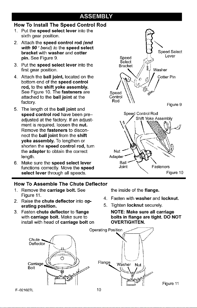
How To Install The Speed Control Rod
1. Put the speed select lever into the
sixth gear position.
I
2. Attach the speed control rod (end _.
with 90 °bend) to the speed select
bracket with washer and cotter Speed Select
Lever
pin. See Figure 9. Speed
Select
3. Put the speed select lever into the Bracket
first gear position.
4. Attach the ball joint, located on the Cotter Pin
bottom end of the speed control
rod, to the shift yoke assembly.
See Figure 10. The fasteners are Speed
attached to the ball joint at the Control
factory. Rod
5. The length ot the ball joint and
speed control rod have been pre-
adjusted at the factory, if an adjust-
ment is required, loosen the nut.
Remove the fasteners to discon-
nect the ball joint from the shift
yoke assembly. To lengthen or
shorten the speed control rod, turn
the adapter to obtain the correct
length.
6. Make sure the speed select lever
functions correctly. Move the speed
select lever through al speeds.
Figure 9
Speed Control Rod
Shift YokeAssembly
Jo _ se eF_gurelo
How To Assemble The Chute Deflector
1. Remove the carriage bolt. See
Figure 11.
2. Raise the chute deflector into oP-
erating position.
3. Fasten chute deflector to flange
with carriage bolt. Make sure to
install with head of carriage bolt on
the inside of the flange.
4. Fasten with washer and Iocknut.
5. Tighten Iocknut securely.
NOTE: Make sure all carriage
bolts in flange are tight. DO NOT
OVERTIGHTEN.
Operating Pos
Chute
Deflector
Carriage
Bolt
F_)21027L
/l
Flang_,Washer Nut
10
Figure 11
Loading ...
Loading ...
Loading ...