Loading ...
Loading ...
Loading ...
49-50336 Rev. 0 11
Installation Instructions
INSTALLATION INSTRUCTIONS
WATER SUPPLY CONNECTIONS
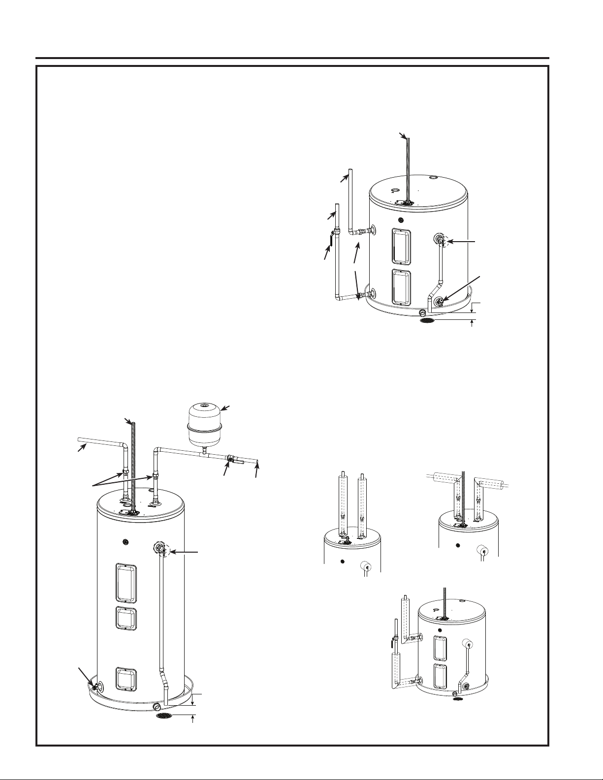
Refer to the illustration below for recommended
installation. The HOT and COLD water connections
are clearly marked and are ¾” NPT on all models.
When connecting to the inlet/outlet ports, the use of ¾”
female NPT tapered thread fittings with use of thread
sealant is recommended. The installation of unions is
recommended on the hot and cold water connections
so that the water heater may be easily disconnected
for servicing if necessary. Piping should be routed to
allow anode rod removal.
NOTE: Install a shut-off valve in the cold water line
near the water heater. This will enable easier service
or maintenance of the unit later.
IMPORTANT: Do not apply heat to the HOT or
COLD water connections. If sweat connections
are used, sweat tubing to adapter before fitting
the adapter to the cold water connections on
heater. Any heat applied to the hot or cold water
connection will permanently damage the internal
plastic lining in these ports.
Install a vacuum relief valve and/or anti-siphon device
when required by local jurisdictions.
TYPICAL TOP CONNECT INSTALLATION
TYPICAL SIDE CONNECT INSTALLATION
(Otherwise same as Top Connect Installation)
HOT AND COLD PIPE INSULATION INSTALLATION
(if supplied with product)
For increased energy efficiency, some water heaters
have been supplied with two 24” sections of pipe
insulation.
Please install the insulation, according to the
illustrations above, that best meets your requirements.
Hot water
outlet to
fixtures
Shut-off valve
To cold
water
supply
Unions
Thermal
expansion
tank
(Install per
manuf.
instructions),
if required
Relief Valve
discharge within
6” of floor and no
closer than 2 times
the pipe diameter
per local code
Temperature &
Pressure Relief Valve
Conduit to Electrical
Junction Box (use only
copper conductors)
(Model appearance
may vary)
Drain valve
To cold
water
supply
Relief Valve
discharge
within 6” of
floor and no
closer than
2 times the
pipe diameter
per local
code
Conduit to Electrical Junction Box
(use only copper conductors)
(Model appearance may vary)
Drain valve
Hot water
outlet to
fixtures
Shut-off
valve
Temperature &
Pressure Relief
Valve
Typical vertical
piping arrangement
Typical horizontal
piping arrangement
Typical side piping
arrangement
Unions
Loading ...
Loading ...
Loading ...