Loading ...
Loading ...
Loading ...
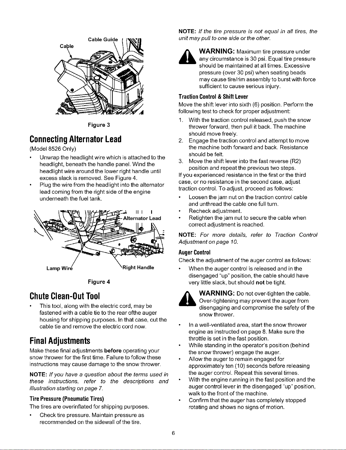
Cable Guide
NOTE: If the tire pressure is not equal in all tires, the
unit may pull to one side or the other.
Figure 3
ConnectingAlternatorLead
(Model 8526 Only)
Unwrap the headlight wire which is attached to the
headlight, beneath the handle panel. Wind the
headlight wire around the lower right handle until
excess slack is removed. See Figure 4.
Plug the wire from the headlight into the alternator
lead coming from the right side of the engine
underneath the fuel tank.
III I
- Alternator Lead
Lamp Wire Right Handle
Figure 4
ChuteClean-OutTool
This tool, along with the electric cord, may be
fastened with a cable tie to the rear ofthe auger
housing for shipping purposes. In that case, cut the
cable tie and remove the electric cord now.
FinalAdjustments
Make these final adjustments before operating your
snow thrower for the first time. Failure to follow these
instructions may cause damage to the snow thrower.
NOTE: If you have a question about the terms used in
these instructions, refer to the descriptions and
illustration starting on page 7.
Tire Pressure (Pneumatic Tires)
The tires are overinflated for shipping purposes.
Check tire pressure. Maintain pressure as
recommended on the sidewall of the tire.
_ WARNING: Maximum tire pressure under
any circumstance is 30 psi. Equal tire pressure
should be maintained at all times. Excessive
pressure (over 30 psi) when seating beads
may cause tire/rim assembly to burst with force
sufficient to cause serious injury.
Traction Control & Shift Lever
Move the shift lever into sixth (6) position. Perform the
following test to check for proper adjustment:
1. With the traction control released, push the snow
thrower forward, then pull it back. The machine
should move freely.
2. Engage the traction control and attempt to move
the machine both forward and back. Resistance
should be felt.
3. Move the shift lever into the fast reverse (R2)
position and repeat the previous two steps.
If you experienced resistance in the first or the third
case, or no resistance in the second case, adjust
traction control. To adjust, proceed as follows:
Loosen the jam nut on the traction control cable
and unthread the cable one full turn.
Recheck adjustment.
Retighten the jam nut to secure the cable when
correct adjustment is reached.
NOTE: For more details, refer to Traction Control
Adjustment on page 10.
AugerControl
Check the adjustment of the auger control as follows:
When the auger control is released and in the
disengaged "up" position, the cable should have
very little slack, but should not be tight.
_ WARNING: Do not over-tighten the cable.
Over-tightening may prevent the auger from
disengaging and compromise the safety of the
snow thrower.
In a well-ventilated area, start the snow thrower
engine as instructed on page 8. Make sure the
throttle is set in the fast position.
While standing in the operator's position (behind
the snow thrower) engage the auger.
Allow the auger to remain engaged for
approximately ten (18) seconds before releasing
the auger control. Repeat this several times.
With the engine running in the fast position and the
auger control lever in the disengaged "up" position,
walk to the front of the machine.
Confirm that the auger has completely stopped
rotating and shows no signs of motion.
Loading ...
Loading ...
Loading ...