Loading ...
Loading ...
Loading ...
MAINTENANCE (Continued)
4. Place pump body half face down on flat surface and tap
out stationary half of seal (see Figure 16).
9. Hold motor shaft with 7/16" open end wrench on shaft
flats (Figure 14, Page 8) and screw impeller onto shaft. Be
sure you do not touch capacitor terminals with
body or any metal object. Tightening impeller will au-
tomatically locate seal in correct position.
10. Remount diffuser on pump body half with five screws.
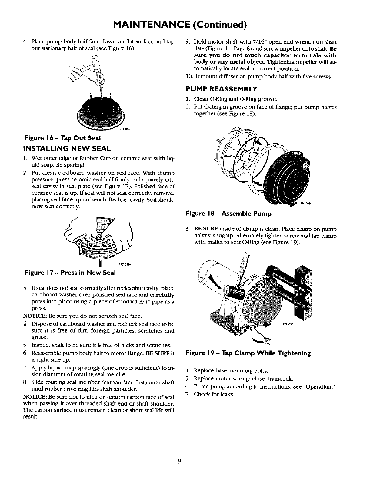
PUMP REASSEMBLY
1. Clean O-Ring and O-Ring groove.
2. Put O-Ring in groove on face of flange; put pump halves
together (see Figure 18).
Figure 16 - Tap Out Seal
INSTALLING NEW SEAL
1. Wet outer edge of Rubber Cup on ceramic seat with fiq-
uid soap. Be sparing!
2. Put clean cardboard washer on seal face. With thumb
pressure, press ceramic seal half firmly and squarely into
seal cavity in seal plate (see Figure 17). Polished face of
ceramic seat is up. If seal will not seat correctly, remove,
placing seal face up on bench. Reclean cavity. Seal should
now seat correctly.
4770194
Figure 17 - Press in New Seal
3. ff seal does not seat correctly after recleaning cavity, place
cardboard washer over polished seal face and carefully
press into place using a piece of standard 3/4" pipe as a
press.
NOTICE: Be sure you do not scratch seal face.
4. Dispose of cardboard washer and recheck seal face to be
sure it is free of dirt, foreign particles, scratches and
grease.
5. Inspect shaft to be sure it is free of nicks and scratches.
6. Reassemble pump body half to motor flange. BE SURE it
is right side up.
7. Apply liquid soap sparingly (one drop is sufftcient) to in-
side diameter of rotating seal member.
8. Slide rotating seal member (carbon face first) onto shaft
tmtil rubber drive ring hits shaft shoulder.
NOTICE: Be sure not to nick or scratch carbon face of seal
when passing it over threaded shaft end or shaft shoulder.
The carbon surface must remain clean or short seat life vdll
result.
Figure 18 - Assemble Pump
3. BE SURE inside of clamp is clean. Place clamp on pump
halves; snug up. Alternately tighten screw and tap clamp
with mallet to seat O-Ring (see Figure 19).
Figure 19 - Tap Clamp While Tightening
4. Replace base mounting bolts.
5. Replace motor wiring; close draincock.
6. Prime pump according to instructions. See "Operation."
7. Check for leaks.
Loading ...
Loading ...
Loading ...