http., lw_ w ,lgscr_ _cc,_x m
AIRCONDITIONE EATPUMP
'S
Ple_e read the o_rating [nstru_ions ,_d safety precautions carefully
_d th,oroughliy before [ns,tallin,g _d o_ratingi yo,ur a,Jrconditioner.
valuable
manual
proof
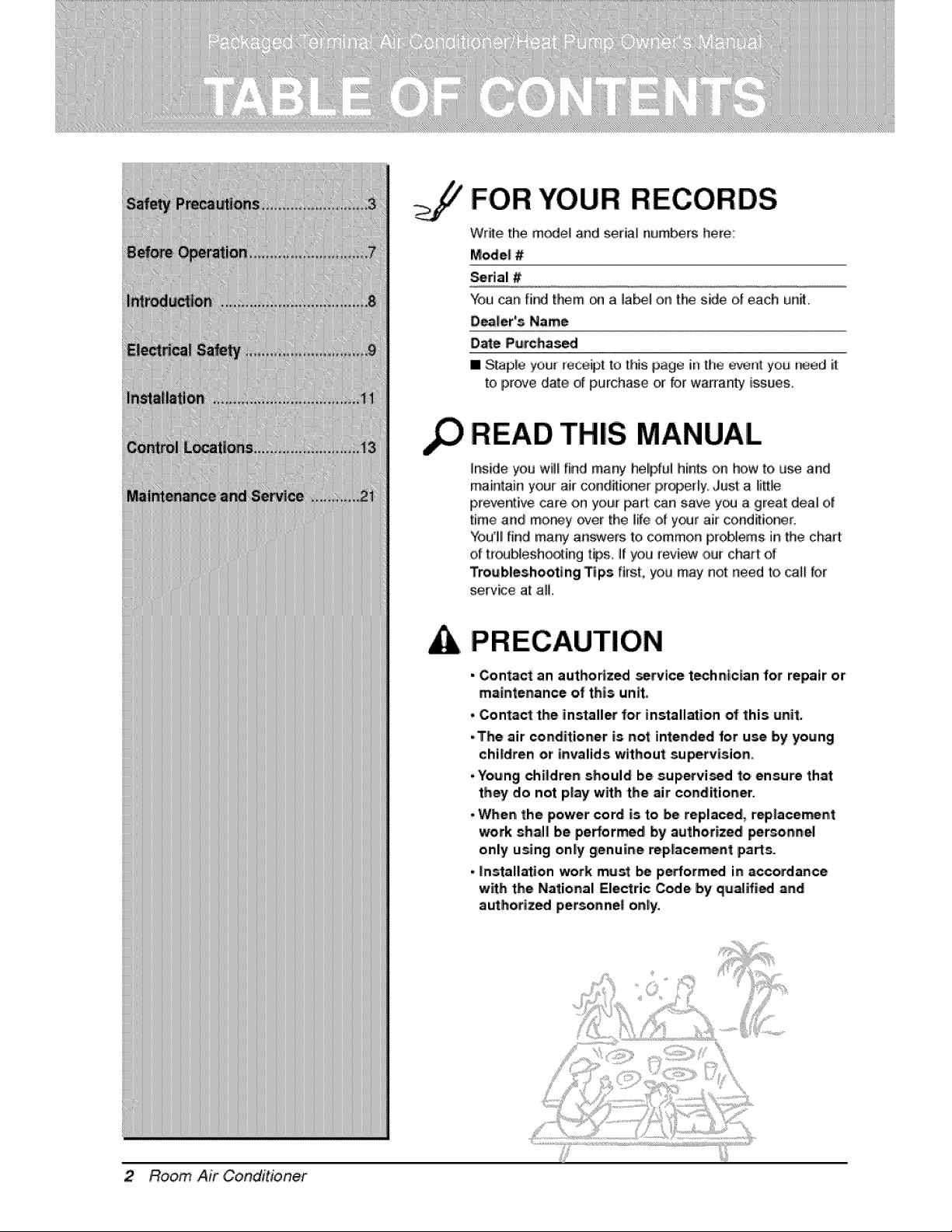
FOR YOUR RECORDS
Write the model and serial numbers here:
Mode| #
Serial #
You can fi_ them on a label on the side of each ue_.
D_i_er's Name
Date Purchas_
III S[ap[e you[ _aceip[ 1o [his page in [he event you [_ed it
to prove d_e of purchase or for warranty issues_
READ THIS MANUAL
inside you will find many helipful hints, on hc_wto use and
maintain your air condit:i(_er pr_eHy: Just: a li_le
p_eventive care on you_ part c:,ansave you a great dea_ o7
time a_ld mo,_y over the life of your air cond_ioner.
You1! |ind many arlswers to common p_lems in the chart
of tr_b_esho_ing t#s. Ill you [eview ,our chair of
Troubles.hooting Tips first:, you may not need to, c,aJlfor
serv_e at ,all,
, Contac_ an autho#z_ _rvice 't_hrtlclan for repair or
maintenance of this unR.
,. Con_ct the installer |or installation of this unit.
.The air conditioner is not intended for use by young
children e.r invalids without supep_tsion.
, Young children should be supervi_ to ensure that
they do not play wRh the air conditioner.
*,When the power cord is to be repla_d, r'ep|ace_n4
work shall be pe,_r'med Iby auth,orized perso, nnel
only using only genui#e mpliace_nt parts.
, installation work must _ p_orm_ in accordance
with the National Eleclric Code by qualifi,_ and
authortz_ personnel o#ly,
2 Room Air Conditioner
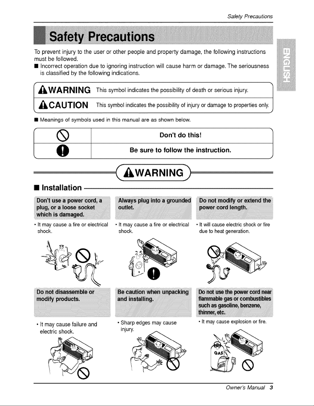
To prevent injury [oi the user o,r other people _d prope_y damage, the bHowiing instructions
must be followed,
[] Incorrect ,opemti,on due to ignoring instruction will cause harm or damage. The seriousness
is classified by the foHowiing indications,
WARNING Th,s sym_l mdl,cates the poss_b_U_yof death r senous _njury,
/, CAUTION Thissyrnbo indicates the possibility .of injury or d_age to. properties only:)
ii Meanings of symbols us_ in this manuaJ are as shown _lo'w°
Don't do this!
B,e sure to follow the instruction,
[] Installation,
• It may cau_ a fire or eJectri_l • It may cause a 'fire ,or electrical
shock sho_,
• It may _use failure and
ellectdc shock.
• Sharp _ges may cau_
injury.
It will _,u_ electric sh_k or fire
due _ heat generahon.
• It may cause exp!_bn or fk'e,
Owner_ Manual 3
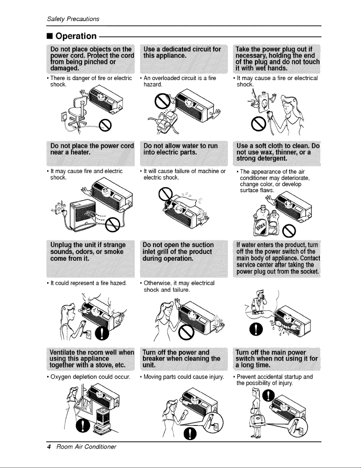
1 Operation
• There =sdanger of fire or eiedric
shock_
• it may cause fire and electric
shock
, I!tcou{d represent a fire hazed,
, Oxygen dep{etion _u{d ,occur,
• An ovedoa_d circuit is a fire
• {t wil{ cause f_lure of machine or
e{ectdc shock.
, Qthe_i_, it may e!_'t:ric_
sho_ and iailure.
, Moving _:s could _use injury,
•. lit may cause a fire or electric_
shock,
, The, @_arance of the air
conditioner may deteriorate,
change eolor.,or d_ve{op
surface flaws.
4 Room Air Conditioner
., Pre,_nt accide_a{ staftup and
the possibility of injury.
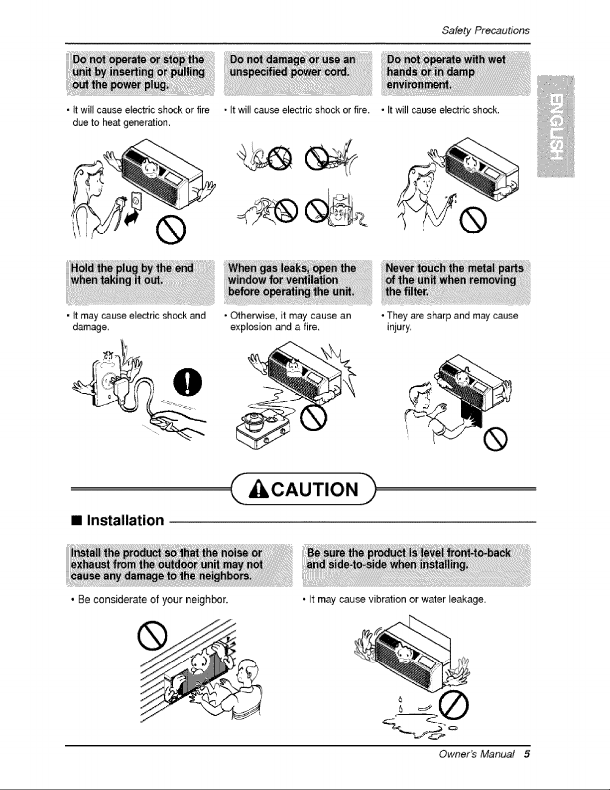
Safety Pr_utions
• _ will _use e_tric shock or fire • litwiB cause electric shock or fire., • It will _u_ electric shock.
due to he_ generation,
• ff may cause eledric sh_k and
_mage
• Qlherwise, ff may cau_ an
explo¢ion and a fire,
i| Installation
• Be considerate of your neighbor.
• They are, sharp and m_ cause
injury,
• It may cause vibral[on or water ileakage.
° 23
Owner_ Manual 5
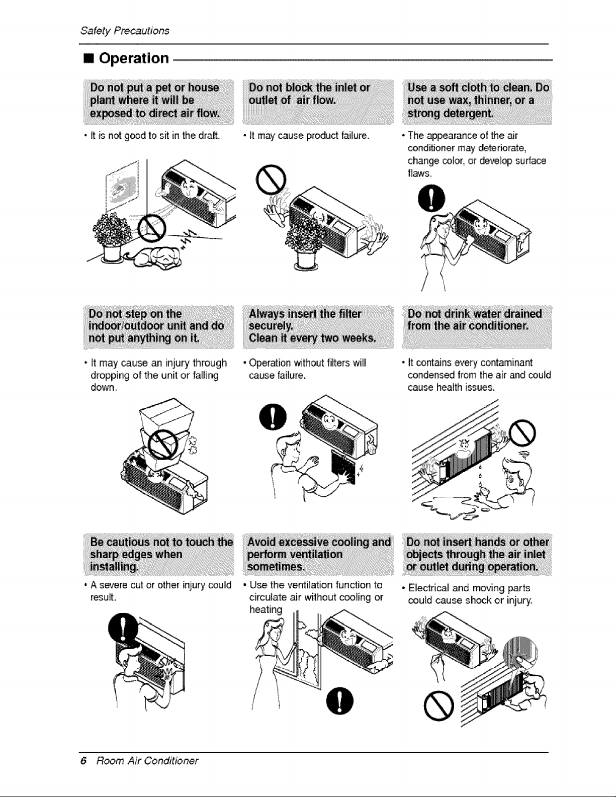
SafetyPrecautions
[] Operation
• ff is not g_d to,sit in the draft. • it may cause product failure. • The appearance o! the air
_nditJoner may deteriorate,
change co,lor_or develop surface
fl,_s,
•, lit may _use an iqury through
dropping o,f the unit ,or fallling
down.,
• Operation wffhout fi_ers will
cause failure
• it co_._ns ,e,_ry cont_inant
condensed from the air and coiu_d
cause health issues.
©
• A s_ere cut or other injury could
resu_.
- Use, the, ventilation fundion to
ci#culate air without coo_ing or
hea'_ing
6 Room Air Conditioner
• Electdc_ and moving parts
could _use shock or injury.
Befo,_ Operation
1i_ Contact an installation specialist for installation.
This is NOT a d,o-_t-yourself project.
2. Plug in the power plug properly.
3. Use a dedicated circuit.
4. IDo not use an extension cord. Consult a professional installer or electrician.
5. Do not start/stop operation by plugging/unplugging the po,wer cord.
6. If the cord/plug iis damaged, replace it with only an authorized replacement
part.
1. Being exposed tO direct airflow for an extended period o,f time could be
hazardous to your health. Do not expose occupants, pets, or plants to direct
airflow for extended periods of time. in other words, don't sit in the draft.
2. Due to the possibility of oxygen deficiency, ventilate the room when used
together with stoves or other heating devices,
3. IDo not use tlhis air conditioner for non-specified special purposes (e.g.
preserving precision devices, food, pets, plants, and art objects). Such usage
could ,damage the items
1. DO not touch the metal parts o,f the unit when removing the filter. IInjuries can
occur when handling sharp metal edges.
2. Do not use water to clean inside the air conditioner. Exposure to water can
destroy the insulation, leading to possible electric shock.
3. When cleaning the unit, first make sure that the power and breaker are turned
off. The fan rotates at a very high speed during operation. There is a
possibility of injury if the unit's power iis accidentally triggered on while
cleaning inner parts of the unit.
For repair and maintenance, ,contact your authorized service dealer.
Owner_ Manual 7
introduction
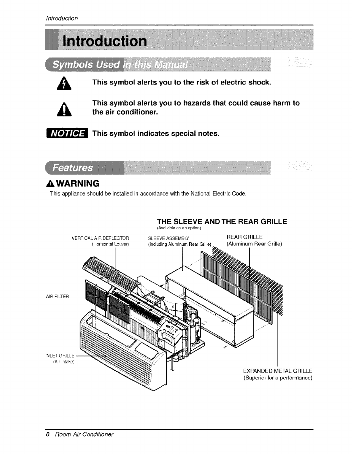
This symbol alerts you to the risk of electric shock,.
This symbol alerts you to hazards that could cause harm to,
the air conditioner.
This symbol indicates, sp_ial notes.
This _pliance should _ ins_Hed in acco,rd_ce with the Nationa_ Electric _,de,
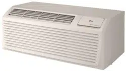
VERTICAL ,AIR DEFLECTOR
(Horizontal l,,,,,ou_ver)
THE SLEEVE AND THE REAR: GRILLE
(Avail_e as an; _t_d}
REAR GRILLE
(Aluminum, ReactGri!le)
{Air I_'_t_e)
EXPANDED,METAL GRILLE
(Su_dor for a p,erforrr_nce,)
8 Room Air Conditioner
El_trical Safety
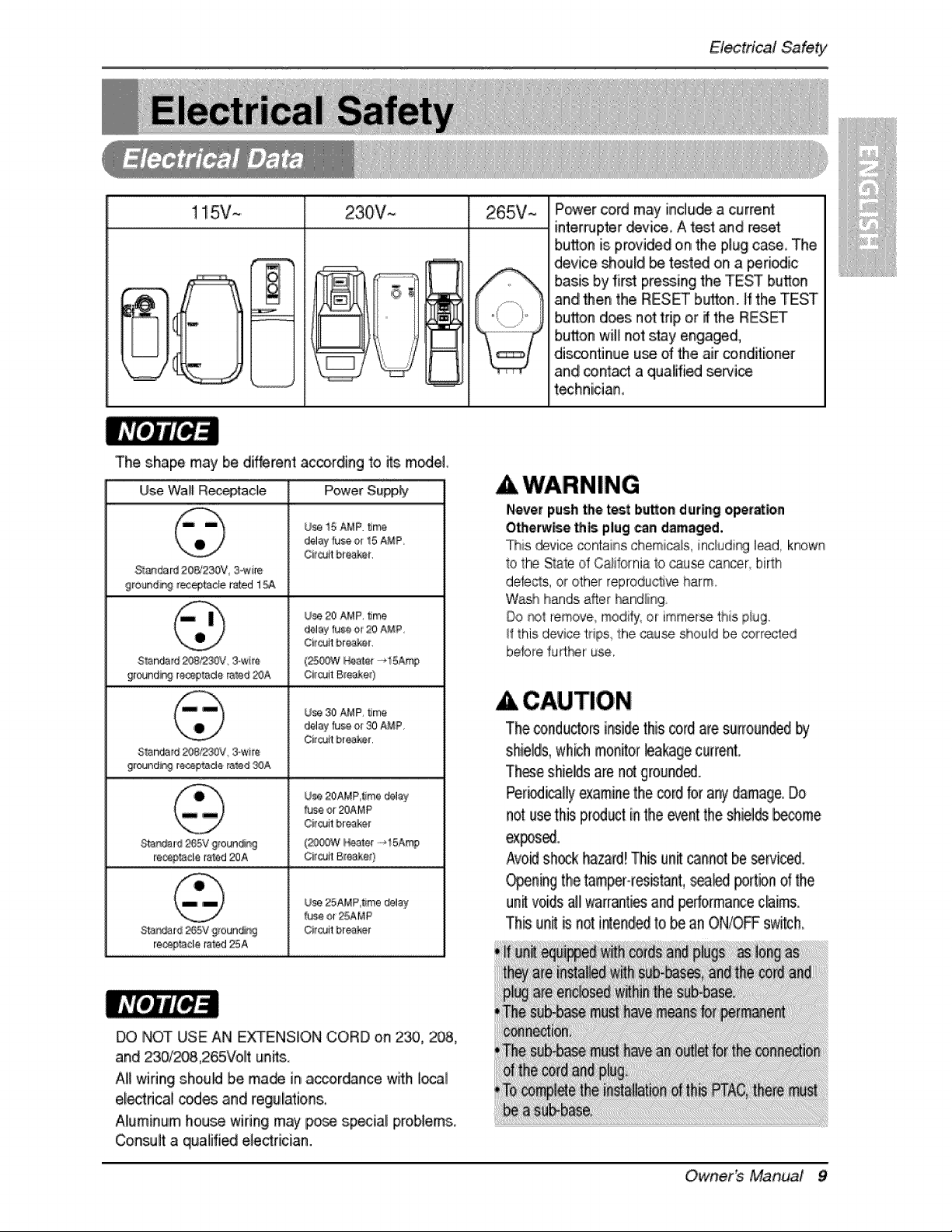
! !5V~ 230V~ 265V~ Power cord may include a current
• - - interrupter _vice_ A test and r_t
T
button is provided on the plug case The
device should _ tested on a periodic
basis by first preying the TEST button
and Hen the RESF button, ff the TEST
bu_on does not trip o.r it the RESET
bu_on will not stay engaged,
discontinue use of the air _nditio,ner
and co_a_ a qua_ifi_ _wi_
techniician,
The shape may be different according to its model,
Use WaltR_tade Power Su_
U_ i5 AMP. _me
delay _J_e ¢_rI5 AMP,
Ct_cutt b_is_ket.
St_dar_ 20&2_V :3_im
9roand#9 _tacle r_ed 1
Use 20 AMP, _me
delay _use ot 20 A#P,
S_nda_d _B2_V_ 3-wi_,a (2_W _ater _15t_rr_
9tound_ r_o_t_da rated _A Circuit Breaker)
Use 30 AMP, _me
delay _u_ er 30 A#P,
Citwlt bie&k_t.
S_ndatd _'2_V, 3-wire
9round_ r_de rated _A
Use 20AMP,_me delay
_u_ or 20AMP
Circuit br,aa_r
Sta_ar_ _65Vgroun_ (_W I_,_ater-_!5A_
[e_ta¢l_ tared 20A CI_'oJit Bmaka¢)
Use 25AMP,_rae delay
_u_ or 25AMP
;Sta_[d 2_}5V groun_ Oi_it br÷a_r
re¢_ta¢le rated25A
Never push _e te_ bu_o,n during ope[at_n
Otherwise Lh_ plug can damaged.
This devic_ _,ntains chem _!s, inc_udi_ lead, known
Io the StaIed California Io @use car_er, biRh
defe¢ls, or other reprodu_ve harm.
W_h hands after I_nd/ing
Do r_)t remove modify, or immerse this piu9..
_I:this device tdps, the @use should be _r_rected
before furtr_r use.
CAUTION
The _nduclo, rs inside this co_dare surrounded #j
shields, which monRorleakagecurrent,
Thee shieildsare n_ grounded.
Per_icaHy examinethe co_dto_an}, damage, Do
not use this p_uct inthe e_nt the shielldsbecome
ex_sed.
Avo_ sh_k hazard! This un_cannot be _¢iced,
O_ning the tamper-resistant,sea_ portion of the
un_ voids alllwarrantiesand pedo[ma_e cairn&
This u_it _ _ot intended to be an ON/OFF swi_h_
DO NOT USE AN E_ENSI,ON CORD on 2_, 2_,
and 230/208,265Voilt unffs.
AI_wiring sho.uM be ma_ in accordance with liocal
electrical c_es and regulations.
Aliuminum house wiring may pose sp_iali problems.
Con_.dt a qualified e]e_rician.
Owner_ Manual 9
(PLEASE READ CAREFULLY3
FOR' THE USER_ PERSONAL SAFET_ _IS
APPLIANCE MUST BE PROPERLY GROUNDED
The power cord of this appiiance is equipped with a
three-prong (grounding) piug, Use this with a standard
threes_ot (grounding) wal_ power outbt to minimize the
hazard of electdc sh_:ko The custorner should have
the wa!l receptacle and circuit checked by a qualified
e_ectrician to make sure the receptacle is properiy
DO NOT CUT OR REMOVE THE THIRD (GROUND)
PRONG FROM THE POWER PLUG.
A. SITUATIONS WHEN THE APPLIANCE WILL BE
D_SCONNLEiCTED OCCASIONALLY
Because of potentia! safety hazards, we strongly
discourage the use of an adapter plug. Howler, if you
wish to use an adapter, a TEMPORARY
CONNECTION may be made, Use ULolisted adapter,
availab!e from most !c_;al hardware stores,
'The _arge slot in the adapter must be aligned with the
i_ge sbt in the receptacle to assure a proper po_adty
,conR@ction.
A CAUTION
Attachingthe _apter groundterminalto the wall
receptacle c_er scr_ d_s not gro,undthe
appliance un_ss the cover_rew is metal,and not
insulated, and the wall recept_le is ground_
throughthe housewiring,The customershouldhave
the circuitchecked_ a qualifiedelectrician to,make
surethe recept_le is ptoper_ g_,unded,
Disconnect the power cord from the adapter, using
one hand on each, Othe_ise, the adapter ground
terminal might bre_ DO NOT LISE the appliance w_h
a broken adapter plug
B, SITUATIONS WHEN THE APPLIANCE WILL BE
DISCONNECTED O_EN
Do not use an adapter plug in these situations,
Unplugging the powe_ cord freque_tly can lead (o a_
eventua_ bre_age of the ground terminal, The wail
power outlet should be replaced by a three-sbt
(grounding) outlet instead.
USE OF EXTENSION _RDS
Because of potentiai safety hazards we _rongly
discourage the use of _ extension cord However, if
you wisih to use an extension _rd use a CSA
certifie_UL,,,,,_isted 3owire (grounding} extension cord,
10 Room AZr Conditioner
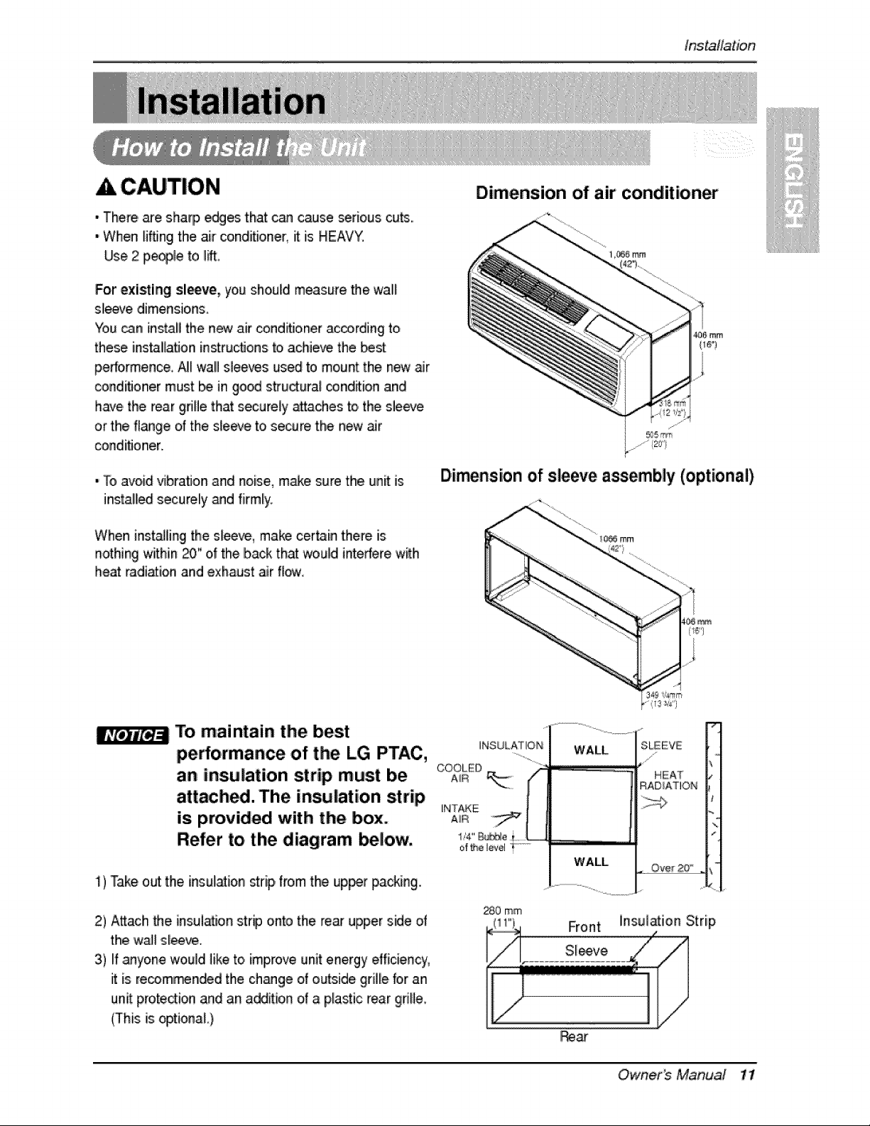
A CAUTION
tns_ffation
•There are sharp edg_ that can cause serious cu_..
• When li'ffJngthe air conditioner, it is HEAVY.
Use 2 pe_le to lift,
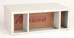
For existing sl_ve, you should measure the wall
sleeve dimensions.
You _nl install the new air conditioner _¢ording to
these ins_llatJon instructionsto achie_ the best
pe#ermence. N! wal!Wsleeves used to mount the new _r
conditioner must _ in good structura_ cond_ion and
have the rear grifle that securely attaches to,the sleeve
or the flange of the s,_eeveto secure the new _r
conditioner,,
•To avoidvibra_onand noise,m_e suretheunE is
installedsecurelyand firmly,
When inlstaJlingthe sleeve, make certain there is
nothing within 20" of the back that would inte_re with
heat ra,di_ion and exhaust aiir fl_
Dimension of air conditioner
1 _6 mm
_6 mm
Dimension of sleeve assembly (optional)
To. maintain the best
pe#ormance of the L.G PTAC, .......
COOLED
an insulation strip must be A_R
attachS. The insiulation strip _NT_E
is provided with the box. A_
Refer to the diagram below. _""_o
of _e I_vel
i) Take out the, insulation strip from the up_r packing.
2) A_ach the insui_on str# onto the re_ upper s_deof
the waJ_sl_.
3) I!f.anyonewould like to improve unit energy efficiency,
it is re_mllmen_d the change of outside grille for an
unit prote_ion and an addition of a p_asti,crear grille
(This is optional )
WALL
WALL
HEAT
%
ZSO mm
Owne. s MaRiua! 11
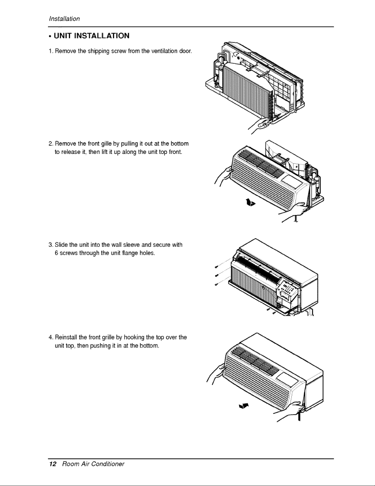
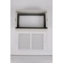
Installation
• UNIT INSTALLATION
1, Remove the ,shipping scr_ from the ve_il_bn _or
2..Remove the fro,_ gibe by pul_ingit o,_ at me bo_:o,m
to,release it, then I[iftit up a_ongthe un_ top front.
3. Slide the unit into the walil s_ee,,eand secure w_h
6 scre_ through the unit flange hol_.
4. Reinstall the front grillie by hooking the top over the
unit t_, _er_ pushing it in _ the bottom,
12 Room Air Conditioner
Con!to!Locations
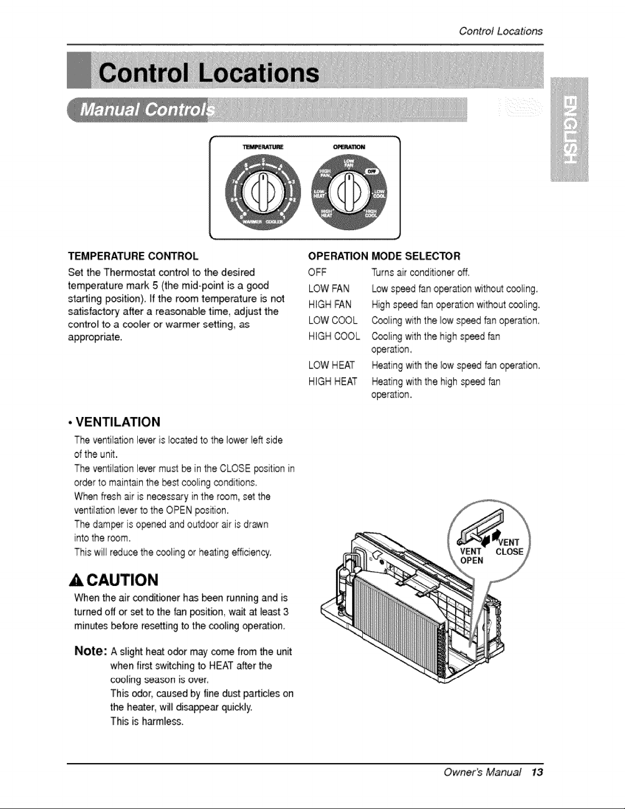
TEMPERATURE COf'_ROL
Set the Thermostat control to the desired
temperature mark 5 (the mid-poin_ is.a good
starting p_itio,n). _'fthe r_m temperature is not
satisfactory after a reasoinabie time, adjust the
control to, a cooler o,r warmer setting,,
appropriate..
OPERA.ON MODE SELECTOR
OFF
LOW FAN
HIGH FAN
LOW C_L
HIGH COOL
Turns air cond_ioner off,
Low speed fan operation without c_ling,
High s_d fan operation witho_l cooling.
Cooling with the low speed _n operation,
Cooling with the high speed fan
LOW HEAT Heating with the bw speed fan o_ration,
HIGH HEAT Heating with the high speed fan
• VENTILATION
The ventilation lever is/_aed to the lower left side
d the unit,,
The ventilation lever mus_ _ in the CLOSE _sition in
order to maintain the best c_ing cgnditions
When fresh air is necessary in the room, set the
ventiiation lever to the OPEN posRion.
The damper is open_ and outdoor air is drawn
into the r_m.
This wi!! r_use the c@ling or h,eaing efficiency'.
A CAUTION
When _e air conditioner has been running and is
turned oft or set to the fan _sitio, n, wait at le_t 3
minutes bebre resetting to the coo,ling op,eration_
Note: A slight heat o_r may come from the unit
when fi_t switching to,HEAT after the
cooling _ason is over:
This odor, caused by fine dust particlies on
the heater, will disa4p_ quickly.
This is harmless.
Owner_ Manua! 13
ControlLocations
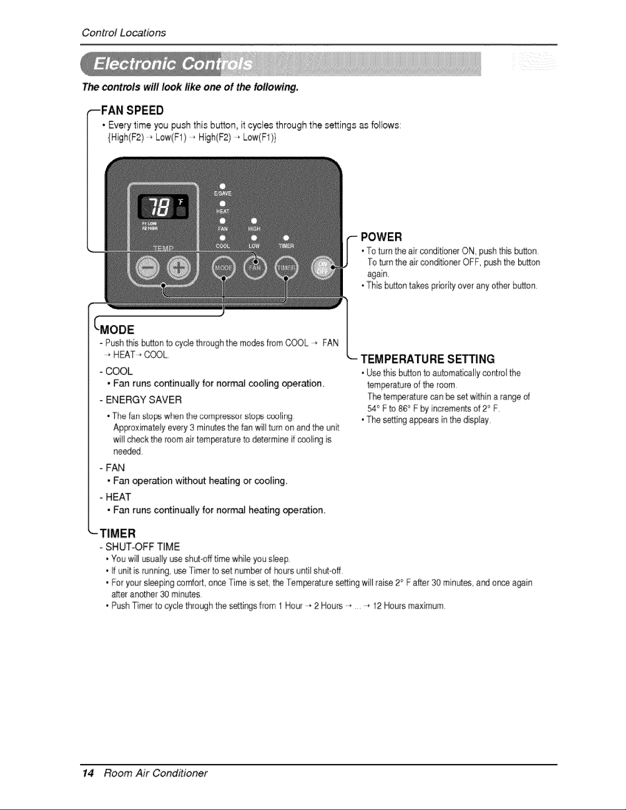
Thecontro/swill'look like one of thei folio,wing,
,--FAN SPEED
* Every time you push this button_ it cycles through the settings _ fo!lows:
{High(F2/-_ Low(F1}-_ High(F2) -,, Low(F1!}
-To turinthe air c_nditionerON,pushthis_bon.
"roturnthe _ _ndi_o_ OFF,push_e button
• Thisbaton takesprbd'tyoveranyotherbutton
- Push'[his,butbn to cyclethrought:kemodesfromCOOL......FAN
-* HEAT-*COOL
- _L
• Fan runs; continually for normal cooling _eratio,n.
- ENERGY SAVER
-The f_n sb_ wher_[he oompressor StOl_ coolir_j,
Approximately every 3 minutes the f_ will turn on and the unit
will check the _oomair temperature to de[e_mir_ if c_ing is
need_.
- FAN
• Fan operation without heating or _oling.
- HEAT
• Fan runs continually for normal heating oper_io,n.
"----TEMPERATURE S,E_NG
• Use this bu_tonto automatically contro_the
tempera_LJreof the room
_e temL_ratu_ecan _ set within a ra%e d
54° F to 86° F by increments of 2° F,
. The setting appears in the d[sp!ay,
oSHUTOFF TIME
.You will _ually u_ sh_°off time whi!e you sleep,
. _ uni_is,running, _se Timer 'b _t number of hours until shu_off
• Fo_you_sl_ping comfort, onc_ Time is set:,the Tem_ature _tting will [raise2° F a#.er30 min_, and once a_in
a_teranode[ 30 minutes.
• Push Timer to e/de through the setti%s f_om 1 Hour -, 2 Hows -*, -_ 12Hours ma×imum,
14 Room Air Conditioner
Control Locations
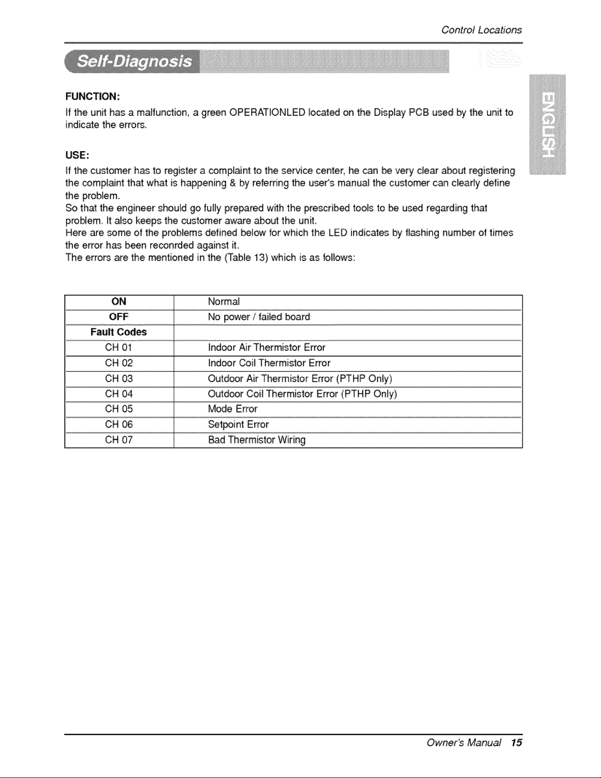
FUNCTION:
if the unit has a malfundion, a green OPERATiONLED located on the Display PC8 used by the unit to
indicate the errors,
USE:
if the customer has to register a _mpl_nt to the servi_ center, he _n be very clear _out registeringi
the _mp_aint that what is happening & by referring the u_r's manual[ the customer can cl!eady define
the problem.
So,that the engineer should go fully prepared w_h the pre_rib_ too,_sto be u_ regarding that
proNem, It al!so keeps the customer aware abo_ the unit
Here .are some of the problems defined bel_ br which the LED indicates by fl_hing num_r ot times
the error has. been reconrded against it,
The erro_ are. the. mentioned in the. ,(Table 13) which is.as bllows:
ON N!ormal
OFF No power / tailed board
Fauff C_es
CH 01 indoor Air Thermistor Error
CH 02 Indoor Coil Thermi_or Error
CH 03
CH O4
CH 05
CH 06
CH O7
OL_door Air Thermistor Error (PTHP Oniy)
O_door ClOi_Thermistor Error (PTHP Onty),
Mode Error
Setpoint Error
Bad Thermistor Wiring
r _Owne, s Manua/ 15
ControlLocations
• REMOVING THE FRONT GRILLE
Additiona_ _ntroB are avmlaMe after
remoqng the front griNe and option
_ver of control box
To/remove the front grille, pub oat the
bottom of from grille and then _ift up
To replace the front griBe, pla_ the t_s
over the top of the unit and push the
bottom of front gril!lleuntil the clip,s sn_
into place
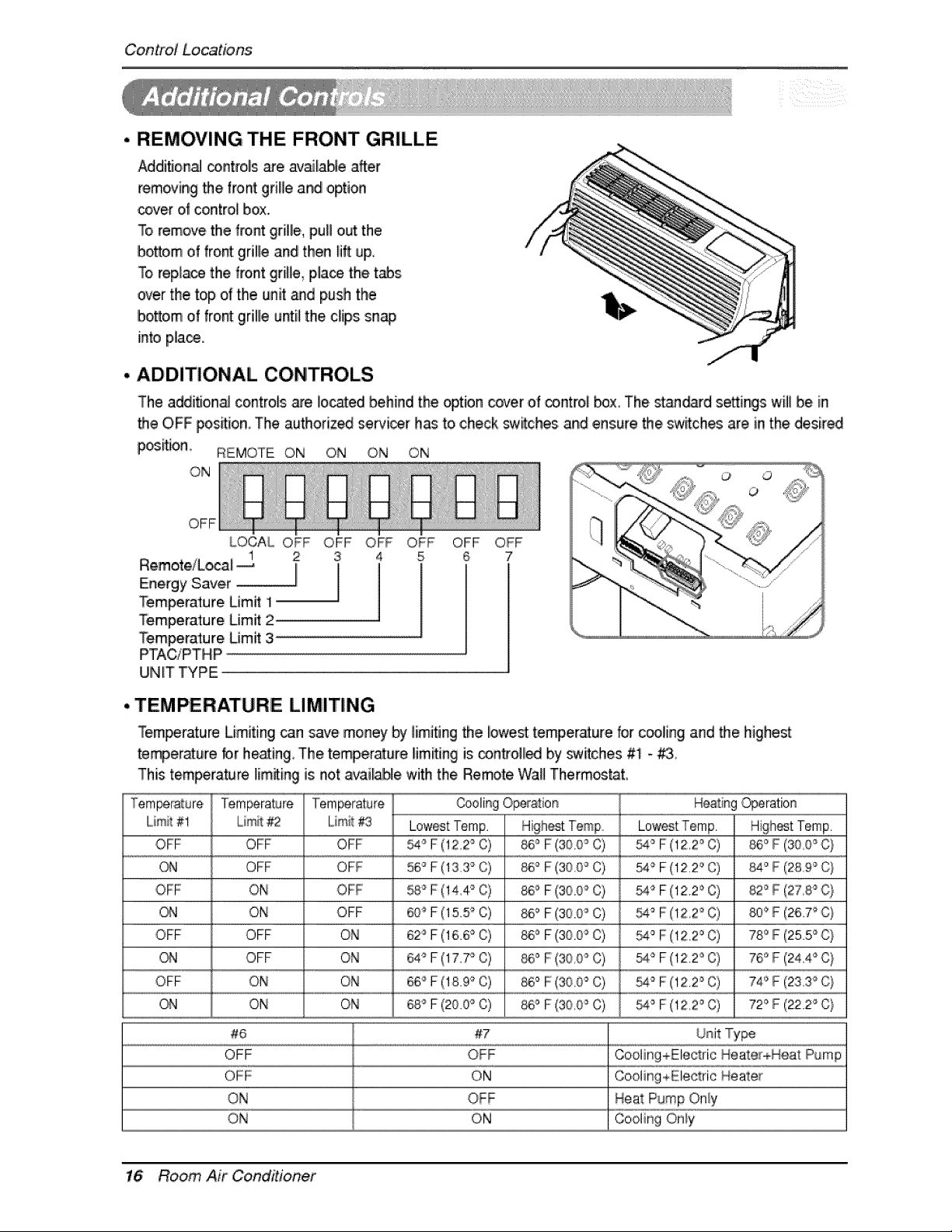
• ADDITIONAL CONTROLS
The addition_ controls are located behind the option c_er of ca ntrol box The stms_rd se_ings will be in
the OFF £os_ion The authorized seHi_r has to check switches and ensure the switch_ are in the desired
p_itJon _ REMOTE ON ON ON ON
'ON
OFF
LOCAL OFF OFF OFF OFF
1 2 3 4, 5
Remote!Local _ I
Energy Siave[ !
Temperature Limit 1
Temperature Limff 2
Temperature Limit 3
PTACiPTHIP
UINIT TYPE
OFF OFF
6 7
o o
o
• TEMPERATURE LIMITING
Temperature Limiting can save money by limiting the iowe_ temper_ure for c_ling and the highe_
temper_ure br he_ing The temper_ure I!im_ing is _n#oll!ed by switches #1 - _
This temperature lim_in,g is not a_i_ble with the Remote WaB Therm_tat,
Tempera£ure _ Temperature Temperature _oling Operation Hea:_ingOperation
L.irr_i_#1 _ Limit #2 Liimit#3 Lowest Temp. Low_t Temp. Hi,gh_t Temp.
OFF OFF OFF _ F (12 2'_C) 86° F (30 0_ C) _° F (!22° C) 86° F°(3O_O_C}
_ ,OFF OFF 56'° F (133 `°C) _° F(300 `°C) __ F(1220 C) 84 ° F: (289 ° C)
OFF ON OFF 58 _F (!44 ° C) _o F(SO.O_ C) _'_ F (12.20 C) 82 _F (27,8_C:}
ON ON OFF @_ F (15.5'_C) 86 _ F (30.0'_C) _ F (! 2 2° C) 800 F (26.7'_C}
OFF OFF ON 62_F (16.6_ C) 86 _ F (30.0'_C) _'° F (!22 ° C) 780 F (25.5_C}
_,1 OFF O_ 64'_'F (17.7_ C) _° F (300 _ C) _'_ F (12.2_ C) 76 '_F (24.4'_C}
OFF ON ON 66_ F (18.9'_C) _,° F (30 0_ C) _'° F (12,2° C) 74'_F (23.3_C:}
QN ON ON __ F (20.@_C) _° F (300 '° C) _ F (122 ° C) 720 F (22.2_C}
#,6 #7
OFF OFF Cooling+Electric HeatereHeat Pump
OFF ON Cooling+Ele_rie Heate_
ON OFF Heat Pump On!y
ON ON Cooling Only
16 Room Air Coinditio_ief
Control Locations
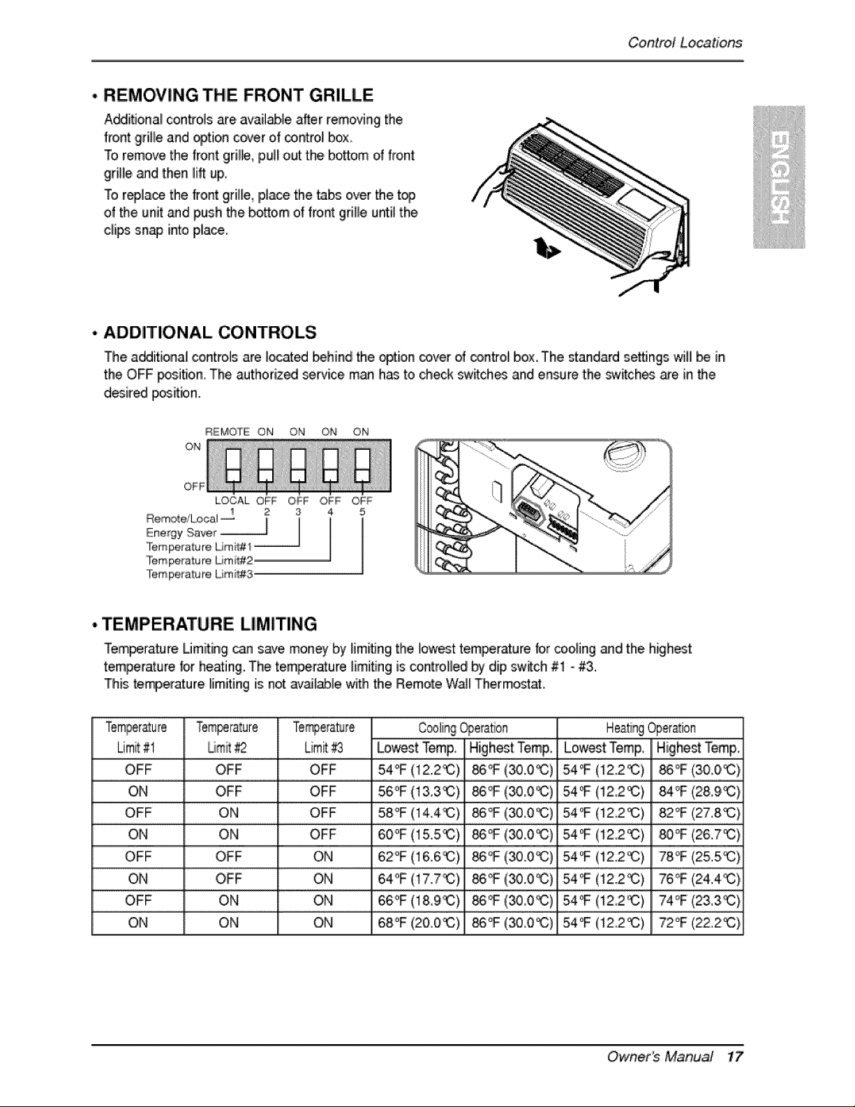
. REMOVING THE FRONT GRILLE
A_iflonal controls are available after removing the
front 9dlle and option cover of _nt_o! box,.
To remove the front grille, pul! out the bosom o_front
grille and then lift up,
To replace the _ront grille, place the tabs over the top
of the unit _d push _e bottom of front grille until the
dips snap into place.
,. ADDITIONAL CONTROLS
The a_itional controls are iocat_ _hind the option cover of _ntrol box. The standard settings willi _ in
the OFF _sitio, n, The authorized service, m_ has to check sw_ches and ensure the _witch_ _e in the
desired position°
OFF
LOCAL OF_ OFF iO_ OF_
2 3 4
Ene'gY Saver _1 [ I
°lemperature Limit# 1
Temperature Umi_#2
Temperature Lira t#3_
• TEMPERATURE LIMITING
Tem_ra_re Umiiting _ save mon_ by limWn9 the [lowesttemperature for co, oiling and the high_t
temperature tor heating. The temperature limitingis controlled by dip sw_ch #1 - #3.
This te_erature limiting is not av_[_le with the Remote Wa_[Thermostat.
Tem_r_u_e Temperature Cooling_era_on HeatingOper_ion
Limit#1 , Um__ , Limit_ , Lo,_st Temp, , Highest Temp, Lewest Temp,, Highest Temp
OFF OFF OFF 54°F (12,2i_) _ (30,0_) 54°F (12.2%3)
ON OFF OFF 56,°F (!&3_) _ (_0_) 54_F (t2,2_)
...............................OFF................................................................°N ....................................................................OEF ........................................5:8"_E{ (300 _ 54 :F(:! 2::2 _ 2:E(2718 _!
ON ON OFF 6,0°F(15.5i_) _(30.0_) 54_(12.2_) 80°F(26,,7_}
OFF OFF ON 62°F(16.6_) _(3,0o0_) 54_(122_) 78°F(25.5._}
ON OFF ON 64°F,(17.7_) _(30.0_) 54_(12.2_) 76°F(24,,4_}
...............................0EE ...............................................................ON......................................................................ON..........................................66 !8:9__C _ (3°
ON ON ON 68°F (20.0_) _°F (30.0_:) 54°F (i22_) 72°F (22,,2_C)
Owne, s Manua[ 17
Contro! Locations
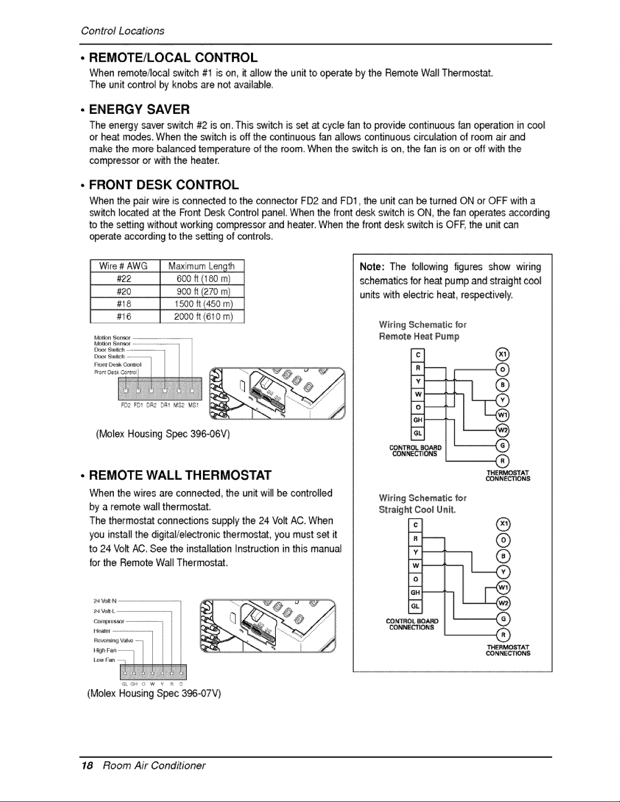
• REMOTE/LOCAL CONTROL
When remote4oca_ switch #1 is on, it _low the unit to o_rate by the Remote W_l Thermos_L
The unit contro_ by knobs are net av_l_le
• ENERGY SAVER
The energy saver switch _ is on This switch is set _ cycle fan to provide continuous _an operation in cool
or heat modes When the switch is off _e cointinuous fan allows continuous circulation of room air and
make the more ba_anc_ temperature of the room When _e switch is on, the fan is on or off wffh tlhe
comlpressor or with the heater
, FRONT DESK CONTROL
When _e _ir wire is _nnect_ to the connector FD2 and FD!, the unit can _ turned ON or OFF with a
switch Io_ted at the Front Desk Contro_p_neL When _e front desk switch is ON, the fan _erates ac_rding
to the setting without working _mpres_r and heater When the front desk sw_ch is OFF the un_ _n
operate ac_rding to the setting of control&
.........Wir:e# AWG......................... ...........
#22
................................#:!8...............................
#__ ........._oo_!_tom)...............
_02 FDI OR2 b_l _$2 t¢ I
(_le,x Housing S_c 396.-06V)
• REMOTE WALL THERMOSTAT
When the wires are co,nn_ed_ _e unit will be controlled
by a remote wail!thermostat,
The thermost_: conn_tions supply the 24 Volt AC. When
you install the digitalielec#onic therm_, you must set it
to 24 Vo_ _,, See the ins_llllation[nstructioin in _is manu_
for the Remote W_I Thermostat.
24 '_N ..................................................................
(Molex Housing Spec 3_07V}
Note: The following figures show wiring
schematics for heat pump and straight icool
units witlheiec#ic heat re_e_ively.
WM#g Schematic f_
¢
y
w_
eL
CONI_,_S
®
®
®
THE_iO_I"AT
_MO_TAT
18 Room Air Conditioner
Control Locations
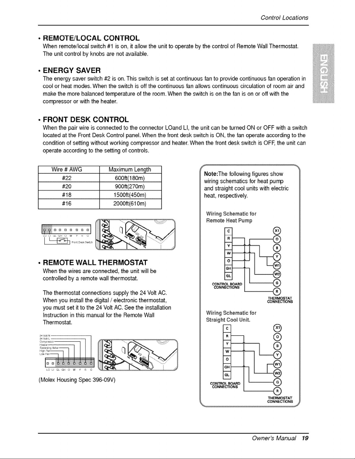
'. REMOTE/LOCAL CONTROL
When remoteil_al swiitch #1 is on, it anew the unit toi operate by the control of Remot8 Wall Therm_t.
The unit con#o! by knobs we not availaNe,
• ENERGY SAVER
The energy saver _¢.4tch#2 is o,n This switch is set at continuous fan to provide continu,ous _n eperatJon in
co,o,_or heat mo,_s. When the switch is off the _ntinuous dan aH_s continuous drculation o,1r_3m air and
m,_e 'the more balan_d temperature o_the r_m, When the switch is on the '{_ is on or off with the
co_ressor or with the heater.
. FRONT DESK CONTROL
_¢_en the pa,ir wire is conn_ed to the connecter LO_d LL the unit can be turned ON or OFF with a switch
i_ated at the _ont D,_k Contro_ paJ_eLWhen the fro_ _sk switch is ON, the fan _erate aocording to,the
condition of setting without working compres_r and heater, When the front d_k _witch is OFE the unit can
o_rate a_ording to the setting of controls.
...............................Wke # ..................................................................M:_im,um _n_th! .......................
.......................................................#_ .......................................................................................................9®_{2ZOm)....................................
..................................................#!8...........................................................................................!#ooff(45£mL...........................
#16 _0_t(6'10m)
, REMOTE WALL THERMOSTAT
When the wires are connectS, the unit wili
cointro,lledlby a remote wa!l thermos_'t.
The thermostat conne_ions supply the 24 Volt AC_
When you instal!the, digi_l / e_ctronic thermostat
you mu_ set it to the 24 Vo,_AC. See the instali[l_:ion
Instruction in this manual for the Remote Wall
Thermost_.
(Molex Housing S_c 396,-_V)
Note:The bllo_ng figures show
wiring schem._cs lor heat pu_
and straight cool units w_h electric
heat, res_cfively.
Wiring Schematic for
Remote Neat Pump
®
-_-
CONN_O_
®
'_M_TAT
CON_ECTIONS
Wida$ _hemat_e for
c_nr_ _o_o
_ONS
®
®
®
TH_PP_TAT
Owne, s Manual 19
ControlLocations
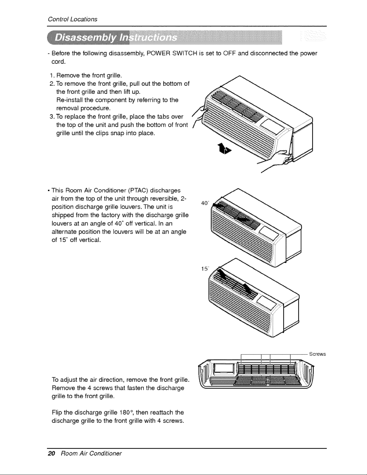
- Before the following disassembly, POWER SWITCH is set to OFF and disconn_ted the power
cord.
1. Remo_e the front grille.
2. To remove the front grill'e, pull out the bottom of
the front grille and then lift up.
Re-install the component by refe_ing to the
removal procure.
3. To replace the front grille, p_ace the tabs over
the top of the unit and! push the bottom of front
grille until the dips sna# into place.
• This Room Air Conditioner (PTAC), discharges
air from the top of the unit through reversii[Ne, 2°
_sition discharge grille I!ouvers. The un_ is
shipped from the factory wiith the di_harge grile
louvers at an angle of 40 ° off ve_ical. In
alternate _s.itio, n the louvers wi
MaintenanceandService
TURN THE AIR CONDITIONER OFF AND REMOVE THE PLUG FROM THE POWER OUTLET
The air fluter should _ checked at least twice a month to _e if cleaning is neces_ry_
Trap,_d particles in the fii'ter will build up and bfock the .aid]ow. This redu_s the cooling
capacity and a_so causes .an a.ccumulatio, n of frost on the cooling coils.
If the filter _mes turn or damaged you should replace
immediately. Replacement riflers are available from your
saJes_rson, dealer, and the authoriz_ customer servi_
centers.
t. Remove the _r filter from the front griBe as_mbly by
p,uHin9 the air rifler up sBghtly.
2 Wash the rifler usingi _ukew_m water below 40°C (104 ° F)
3:. Ge_iy shake the excess water from the fillter completely.
Replace the filter.
Before c_eaning the vent rifler, disconnect [_wer to the
unit _ unplugging the power cord at the wall] outlet or
subbase,, or disconnect power at the fuse box or circuit
breaker. If unit is operated with vent _or c]o,_d, the
vent filter does. not need to be c_eaned.
1. Remove the cabinet front as d,escribe,d in Front
Rem,oiv_,
2, Remove the six screws secudng the chassis to the
waJ] sleeve w_h a Phillips-Head screwdriver.
3.. Slide the chassis out of the w_l sleeve far enough
so that the vent fiffer is a_essiNe as. shown [in
Rgure A_
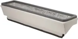
4, Remove the, vent fiffer _ unscrewir_ the two screws
at the top of the f[ffer _d gently pulling the rifler
away _om the partition _ne], Refer to, Figure B,
5. Clean and replace the fi_ter by rea_aching the hook
to the bottom of the vent door and replacing the two
_r.ews, slide the chassis [back into the waB sleeve,
_ure it in p_ace with six screws and reinstall the
front canner.
Figure A Vent (Left side of unit:)
Figure B = Vent Fi_terRemoval
Owne s Maniua[ 21
Maintenanceand Service
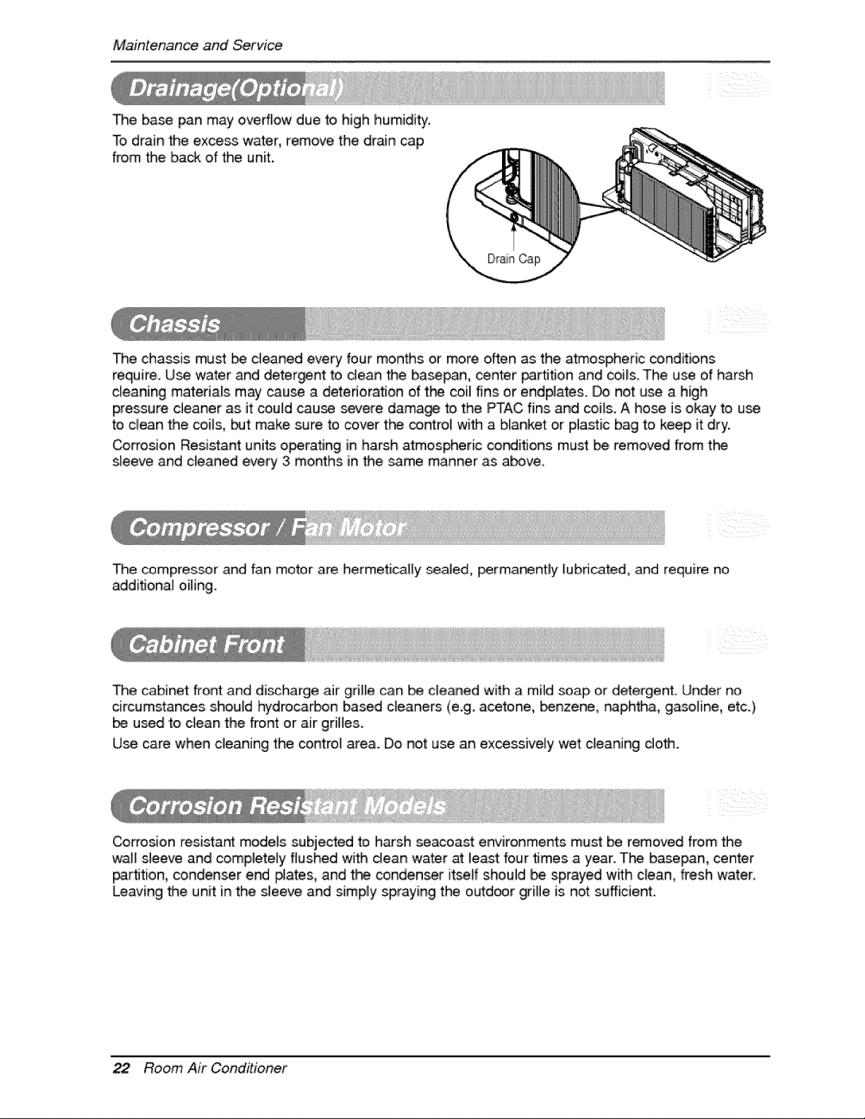
The base pan may ,overf!ow due to high humidi_
To drain the excess water, remove the drain cap
from the ib.ac_,of the unit.
The cha_is must _ cleaned every four months or more often as the atmospheric conditions
require. U_ water and detergent to dean the ba_n, center _rtition and coils. The use of harsh
cleaning materials may cause a deterioration of the coil fins or endplates. _ not u_ a high
pressure cleaner as it could cause severe damage to the PTAC fins and _i_s. A hose is okay to use
to clean the coils, but make sure to cover the control with a blanket: or plastic bag to keep it dry.
Corrosion Resistant units o_rating in harsh atmospheric conditions must bie removed from the
s_eeve and cleaned every 3 months in the _.me manner as above.
The compressor and fan motor are hermeti_[y _a[ed, _rma_ntliy lub,dcated, and require no
addi_onal oiiling_
The cabinet front and di_harge air grille can _ cleaned with a mild soap or detergent Under no
circumstances sho_._idhydroca_,o,n based cleaners (e.g. acetone, _nzene, naphtha, gasoline, etc.)
used to c_ean the front or air grilles.
Use ,care when cleaning the contro_ area. Do not u_ an excessively wet c_eaning cloth.
Corrosion resistant modeis subjected to harsh seacoast environments must be removed from the
wa_l sleeve and completely flushed with dean water at least four _mes a year.. The basepan, center
_rtition, condenser ,end #ates, and the condenser itself should _ sprayed with clea.n, fresh water.
Leaving the unit in the slleeve and simply spraying the outdoor grille is. not srufficient,
22 Room Air Conditioner
MaintenanceandService
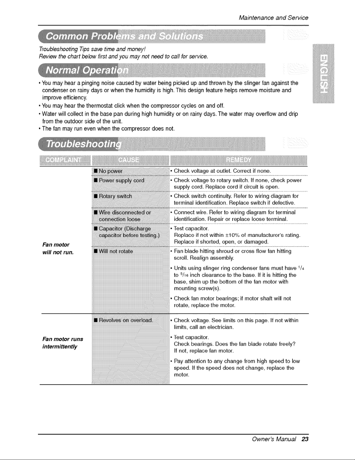
TroubleshootingTipssa_ timeand_y!
Review the ,chart _#w first and you may _t n_ to _fl for serve,
, "Youmay hear a pinging noise caused by water _ing picked up and thrown _ the slinger fan ._ainst the
conden_r on r_ny days or when thle humidly is high. This _sign feature he[_ remove moisture and
improve efficiency,
, You may hear the thermo_at dick when the compres_r cycl_ on and off_
* Win'el will co,llect in _e base p_ dudngi high humidity or on rainy days, The water may oveflow _d drip
from the outdoor si_ of the un_,
, The fan may run even when the oompressor does not.
Fan motor
will _t run,
Fan motor runs
iiiiiiiiiiiiiiiiiiiiiiiiiiiiiiiiiiiiiiiiiiiiiiiiiiiiiiiiiiiiiiiiiiiiiiiiiiiiiiiiiiiiiiiiiiiiiiiiiiiiiiiiiiiiiiiiiiiiiiiiiiiiiiiiiiiiiiiiiiiiiiiiiiiiiiiiiiiiiiiiiiiiiiiiiiiiiiiiiiiiiiiiiiiiiiiiiiii
iiiiiiiiiiiiiiiiiiiiiiiiiiiiiiiiiiiiiiiiiiiiiiiiiiiiiiiiiiiiiiiiiiiiiiiiiiiiiiiiiiiiiiiiiiiiiiiiiiiiiiiiiiiiiiiiiiiiiiiiiiiiiiiiiiiiiiiiiiiiiiiiiiiiiiii@iiiiiiiiiiiii
iiiiiiiiiiiiiiiiiiiiiiiiiiiiiiiiiiiiiiiiiiiiiiiiiiiiiiiiiiiiiiiiiiiiiiiiiiiiiiiiiiiiiiiiiiiiiiiiiiiiiiiiiiiiiiiiiiiiiiiiiiiiiiiiiiiiiiiiiiiiiiiiiiiiiiiiiiiiiiiiBi_i_i_i_i_i_i_i_i_i_i_i_i_i_i
iiiiiiiiiiiiiiiiiiiiiiiiiiiiiiiiiiiiiiiiiiiiiiiiiiiiiiiiiiiiiiiiiiiiiiiiiiiiiiiiiiiiiiiiiiiiiiiiiiiiiiiiiiiiiiiiiiiiiiiiiiiiiiiiiiiiiiiiiiiiiiiiiii@i
Check voyage at outbL Correct if none..
Ch_k vottage to rotary switch, if none, ch_;k power
supply ,cord. Replace cord if drcuit is open
Check _itch continui_: Refer to widng diagram for
termin_ identification° Replace swath if _|ective
Connect wire. Re|er to wiring diagram for terminal
identifi_[on Repair or replace Iioose terminal.
Test capacitor_
R_[ace if no_ within +_10% o,f manufac|uror's ruling
R_[aco if shorted, open: or _maged.
Fan blade hi_ing shroud or cross _bw fan hitting
_ro& Realign assembly_
Units using slinger ring condenser fans must have V4
to 5/_ inch clearance to the base. H _ is hi_ing the
base., shim up the bottom of the fan motor w_h
mounting sct_(s).
Check fan motor b_arings; if motor shaft wi_[ not
rotate, replace the motor.
Check voi[t:age See limits on this page. Iif not w_hin
lim_s, carl an electrician,
_lest c_acitor.
Check bearings. Does the fan blade _otate free_y?
If not, rep!ace fan motor°
Pay attent:io_ to _y change |rein high £Oe_ to low
_,e_. if _e s_ed d_s not change, replace the
motor
r _Owne s Maniua! 23
Maintenance ,and Service
Fan motor _ise.
will
not run, but fan
motor runs.
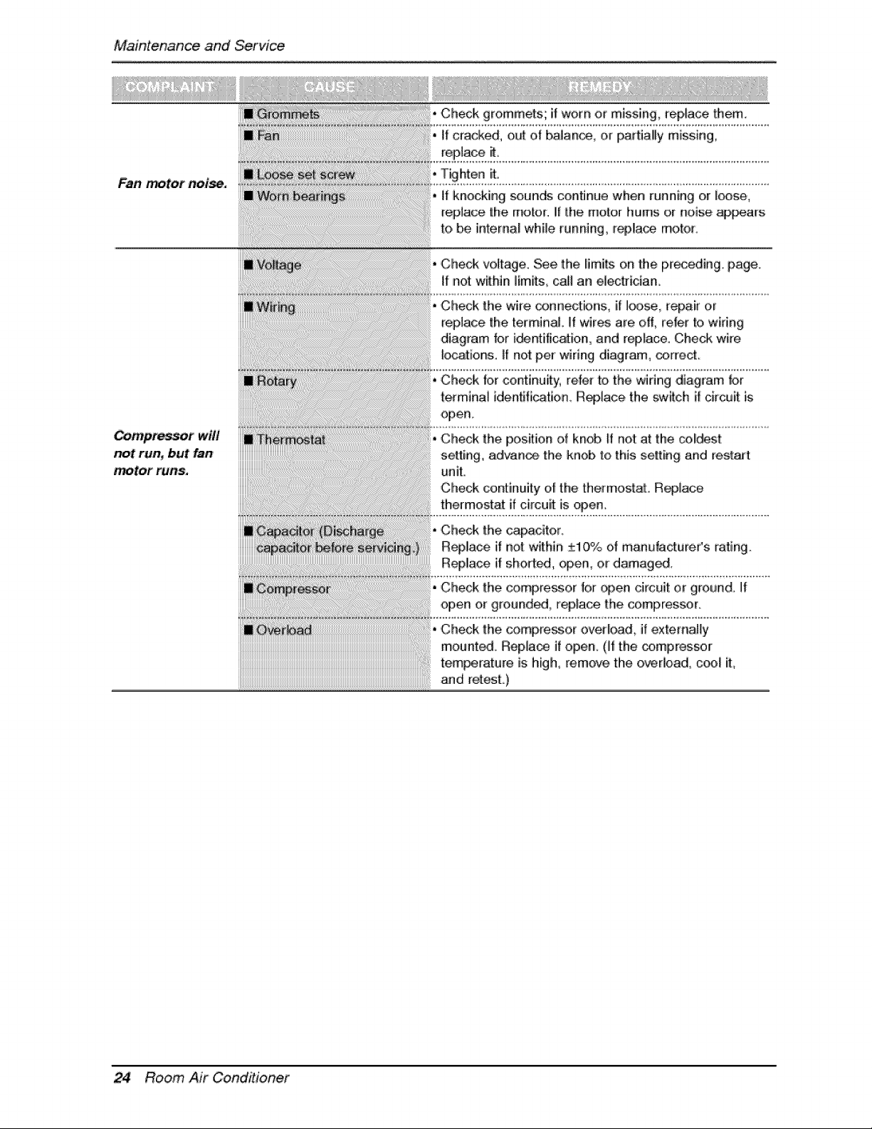
Check grommets; it worn or missing, replace them.,
* if cracked, oiLjt of balance, or _t:iallly missing,
roplace _.
l_hten it.
,i if knock ng sounds contJnue when running or f_se
replace [he rno[or, iif the motor |lurns or noise ap,_ars
to, be infernal while running, r@lace motor:
Check w_]tage. See the limRs on the pr_eding, page.
if not: within ]imits_ call an e]ectrician.
Check the, wi#e _nnections, it !oo_, re.Jr or
replace '[he terminal ]f wir_ are off, refer '[o wiring
diagram for i_ntification, and replace. Che_ wire
_ocations. tt nat per wiring diagram, correct
Check for continuity, refer to the wiring diagram for
terminal i,dentffi_ion, Replace, the switch if circuit is
open°
Check the, po,sRion of kn@ If not: at the c#!@s!
setting, 8d'_ance the knob to this s÷lLting and rest_t
unit°
Check cointinuity oli the thermostat. Replace
thermostat if circuit is _en,
Check the compresso,r for open circuit ,or ground, if
open o,r ground_, _eplace the co,represser.
Check the compressor ,overl@d_ if externai[y
mounted_ Rep]a_ if open Ot the compres_r
temperature is high remove the ovefloa& cool lit
and retest.)
24 Room ALr Conditioner
MaintenanceandService
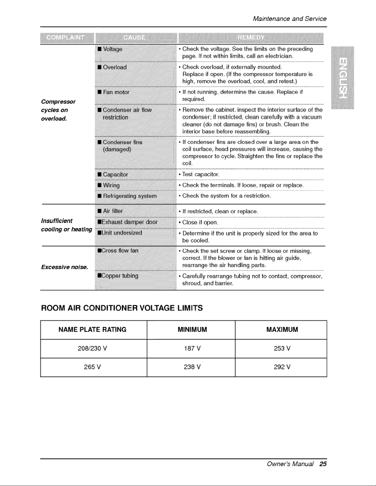
cydes oni
overload,
insufficient
cooling or heating
noise.
• Check overlload, if externaJ_y mountS,
Replace it open. (ff the compressor temperature is
high, remove the overload, c_l, and refesL)
* tf not running, determine the cause Replace if
r_uired.
• Remove the cabinet, inspect the intedo,r surfa_ of the
o_mden_r; it r_tdct_, clean carefully with a vacuum
cleaner (_ not damage tins) or brush Cliean the
_nteriior base _fore reassembling.
• _f condenser '_ns are c_o_,d ,over a large area on the
_il sur{ace, head pressures wilil increase, _using the
compressor to cycle. Straighten the fins or replace the
®iL
• T_t c_acitor.
• Ch_sk the terminals° If loose, r_air 0it r_,ce.
- CheeA the system for a r_trieti'oiR,
, Determine if the unit is properly sized for the i_ea to
c_led.
• Check the set screw or damp IIf loose or missing_
_rrect. if the blower or _n is hitting air gui_,
rearrange the air handling parts
•Caretul]y _earrang,etubing not to contact, comp,r_sor,
shroud, and barrier.
ROOM AIR CONDmONER VOLTAGE LIMITS
NAME PLATE RATING MINIMUM MAXIMUM
208/230 V 187 V 253 V
265 V 238 V _2 V
Owner_ Manua! 25
Nota
50 Aparatodeaireacondicionado
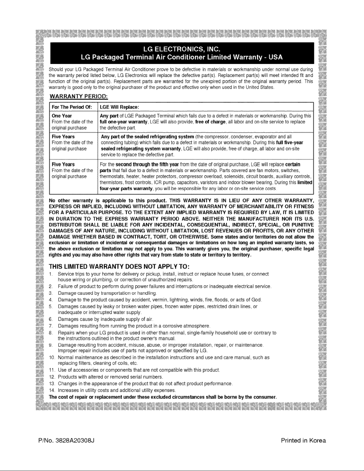
Should you__LG Packag_ Terminai Air Cond_ione[prove to be defective in materials or woAmanship under normal use during
the warranty _er_tJ _ist_ below, LG Eled_onI_ wlHr_la_ the def_tlve paH:(s)R_la_me_t pa_t(s)will m_'[ Intended f_ and
function of the original part{s) Repta_ment pa_s a_e warra_t_ for the u_expir_ po_ion of the o_ginal warranty period This
warranty is g,_ o_y to the ,ordinalpurcha®er_'of the produc_a_de'ffeciiveor_y'whenu,'_d in the United Siate_
WARRANTY PERIOD:
F_ i_e Period _:: LG£ V'_l|Re_ce:
_e Ye_ Any _ of LG_ Packaged"_'erminalwhich fai_sdue to a def_ in materialsor workmansh_ D_r_g thi_
From the date of the full _-ye_ wanaaty LGE will also provide,_i of _r_, _] _r ,andO_ositeservice _o_ep_ace
original purchase the defect_e _rt
Rye Years Any _ of t_ sealed refdgeraBng system (_hecompressor condenser evaporator,andalll
Fromthe date of the connectingtubing) whichfails due to a defe_ in matefla_sor workmansh# Du_g 'Ih_ f_il live-y_r
o_iginalpurchase _ _e_d_g sy_ war_, LGEwll! also p_ovide,f_eeof cha_ge,al_labor arid on-si_e
sewice to _epiacethe defective p_A
F{ve Y_fs
From the da_e of the
o=riginaipurchase
Fo_the sec_d tLe_ t_h y_ fro_ the date d o_iginalpurchase,LGE 'willreplace_n
_rts that fa_tdueto a ddect/n materials or wor_a_sh_p. Pa_s _vered are fan motors: sw_[_ches,
thermostats heater, healierprotectors,compl'_SOt overload, solenoids,circuit boards,au× liary ®ntrols,
thermistor, host _o#tro_s ICR pump,capacitors varis_oBand indoo_blower bearing During_hisllmi_
f_ar-y_r p_s war_. yo_ wll! _ _es_ns_le for _y _abo_or on_s_ese¢_loecosts
NIo _ w'ar[a_y is appi_able to=|his pr_uct.. TH_ WARRA_ _ iN L|EU OF ANY OTHER WARRANTY.,
EXPRESS _ IMPLIED,,|NC:iLLIDIif'_ WITHOUT LIMiTAT_N, ANY WARRANTY OF M£RCHANTABILWY OR FITNESS _
FOR A PARTICULAR PURPOSE. TO THE EXTE_ ANY ilMPLIIIEDWARRANTY IS IREQ_IRED BY LAW, IT IS LIM_ID _;_";_
iN D_RAT_ON TO TBE EXPRESS WARRANTY _RIOD ABOVE. NETHER THE MANUFACTURER N_ ITS _,S, _;_,_,
DISTRIBUTOR SHALL 8E LIABLE FOR ANY INCIDENTAL, ,COiNSIEQLIENTIAL,iND|RECT, SPECIAL, OR PtJNIT|VE
DAMAGES OF ANY NATURE, |NCL_D|NG WITHOUT L|MITAT|_ LOST REVENUES O.R PROFITS.,OR ANY OT_IER _i;_i
DAMAGE WH_HER BASED |N CONTRACT, TO._, OR OTHE_iSE. _e _es _d,_= ter_ori_; _i r_ alll_ _,
exclusio_ o_ ltmitaS_ of Inc_ie_ _ c_uenitla| _ or Illm_io_ on how I1_ a_ i_|i_ wa_ I_s, so 4;_;
_, above ex_on= o_ I_i_a_ i_ not _'y to y_.. This w_ty giv_ 'y_J, t_ _nal _rc_, s_ic I_
rights_ yoe maryal_ have oth_ rightst_ varyfrom _ate to state or te_ory to _rrit_.
THIS LIiM_ED WARRA_Y DOES NOT APPLY _O:
1, Sewice trips to your L_mefor delivery or pickup, install inst_ct or re_ace _use fuses, or _nne_
house widn9 or plumbing, or corr_tion of unauthoriz_ re_irs.
2, Failu_ of product to _fform during Fx}werfailures and int_ruptions or inad_ua_e eiectdcai _wice.
3. Damage _used by _arls_rt_ion o_ har_dling
4, Damage to the product _uaed by accident, vermin, lightning, wi_s, fire, floods or a_s of _d
5. D,amagesca_J_d by _eakyor broken w_ier pi_s frozen water pip_,, restr _ drain lines, or
_nadequateor interfused water supply.
6. D,amag_ cause by ina®quate s,uppiy of air.
7r Damag_ resul_ng from tuna ng the product in a corrosive atmosphere
8, Repairs when _ur LG product is _d in o_er than normal single-_ami_yho_ehold u_ or contra_ to
the Instr_ons outlin_ i_ _heproduct ow_ner_manual
9. Damage resuiting from accident, misuse, abut, air mpro_r installation, re_ir, or mainten_ce_
Impro_r repair inchJdesuse,d _£s not app_v_ or s[_cifi_ by LG
10 Normal maintena[_e as described in the ins_HatJoninstructions and _e and care manual such as
re#acing filters cleaning of @i_s,elc
Use d acces_fies or com_nents that are not @mpatibie with _is prod_t.
Products w_h a£ered or removed _ria_ numbers.
Ohanges in the ap_a[ance of the product that do not affect product _rforman_,
P'!No, 3828A203:08iJ Print_ inKorea