Loading ...
Loading ...
Loading ...
Forbestresults,tapthebumpknobonbaregroundorhardsoil.If
attemptingalinereleaseintallgrass,theenginemaystall.
NOTE:DonotresttheBumpHeadTM on the ground while the unit is running.
Some line breakage will occur from:
• Entanglement with foreign matter
• Normal line fatigue
Attempting to cut thick, stalky weeds
Forcing the line into objects such as walls or fence posts
TIPS FOR BEST TRIMMING RESULTS
Keep the cutting head parallel to the ground.
Do not force the cutting head. Allow the tip of the line to do the cutting,
especially along walls. Cutting with more than the tip will reduce cutting
efficiency and may overload the engine.
Cut grass over 8 inches (200 mm) by working from top to bottom in small
increments to avoid premature line wear or engine drag.
Cut from right to left whenever possible. Cutting to the left improves the
unit's cutting efficiency. Clippings are thrown away from the operator.
Slowly move the unit into and out of the cutting area at the desired height.
Move either in a forward-backward or side-to-side motion. Cutting shorter
lengths produces the best results.
Trim only when grass and weeds are dry.
• The life of the cutting line is dependent upon:
Following the trimming techniques
What vegetation is being cut
Where vegetation is cut
For example, the line will wear
faster when trimming against a
foundation wall as opposed to
trimming around a tree.
DECORATIVE TRIMMING
Decorative trimming is
accomplished by removing all
vegetation around trees, posts,
fences, etc..
Rotate the whole unit so that the
cutting head is at a 30 ° angle to
the ground (Fig. 13).
30 °
Fig. 13
MAINTENANCE SCHEDULE
_ ARNING: To prevent serious injury, never perform
maintenance or repairs with unit running. Always service and
repair a cool unit. Disconnect the spark plug wire to ensure that
the unit cannot start.
Perform these required maintenance procedures at the frequency stated in
the table. These procedures should also be a part of any seasonal tune-up.
NOTE: Some maintenance procedures may require special tools or skills. If
unsure about these procedures take the unit to Craftsman or other
qualified service dealer. Call 1-800-4-MY-HOME ®for more information.
NOTE: Maintenance, replacement, or repair of the emission control devices
and system may be performed by a Craftsman or other qualified
service dealer. Call 1=800=4=MY=HOME ®for more information.
FREQUENCY MAINTENANCE REQUIRED SEE
Before starting engine Fill fuel tank with fresh fuel 3.5
Every 10 hours Clean and re-oil air filter 3.8
Every 25 hours Check spark plug condition and gap 3.8
LiNE INSTALLATION
_ ARNING: Never use metal-reinforced line, wire, chain or
rope. These can break off and become dangerous projectiles.
This section covers both SplitLine® and standard single line installation.
Always use original equipment manufacturer 0.095 in. (2.41 ram}
replacement line. Line other than the specified may make the engine
overheat or fail.
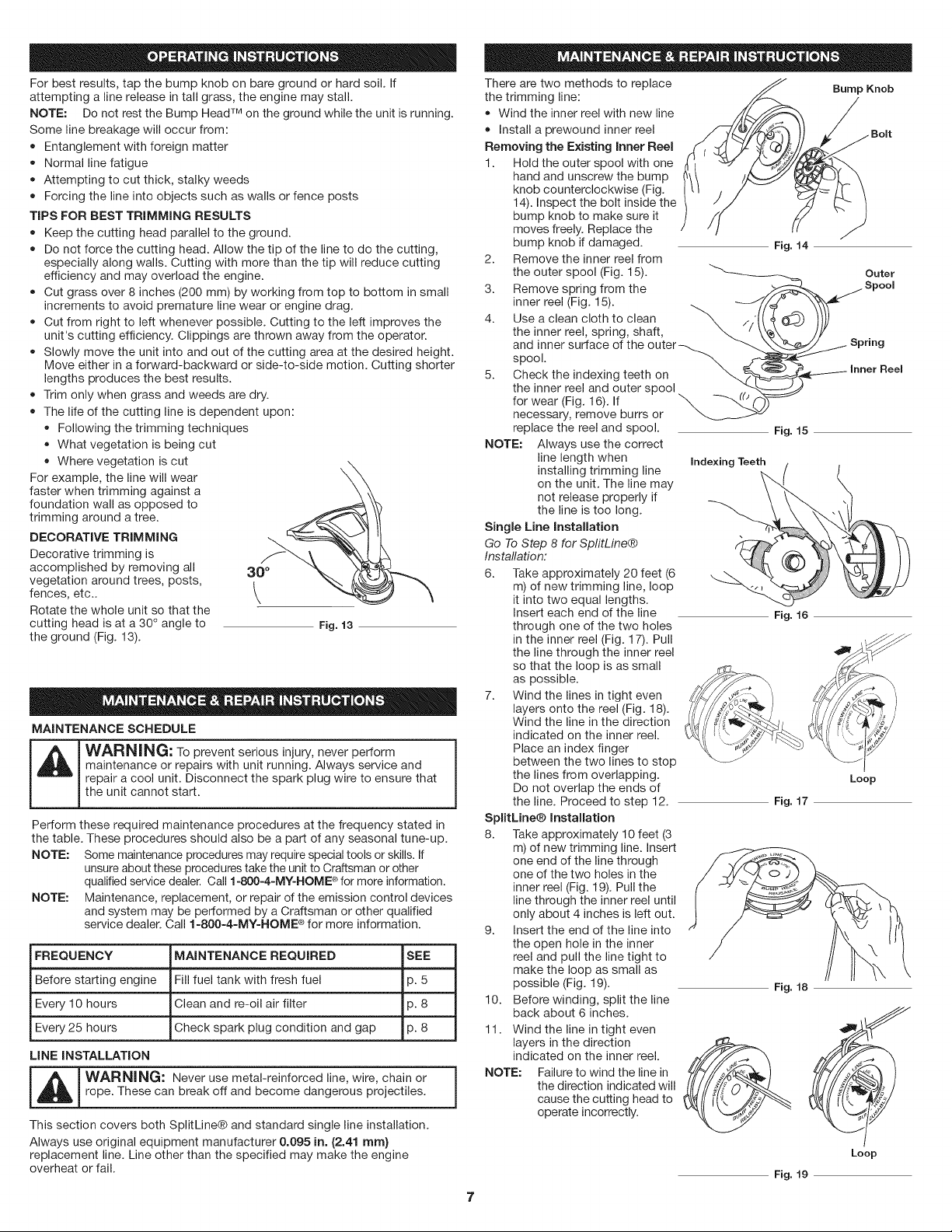
There are two methods to replace
the trimming line:
• Wind the inner reel with new line
Install a prewound inner reel
Removing the Existing Inner Reel
1. Hold the outer spool with one
hand and unscrew the bump
knob counterclockwise (Fig.
14). Inspect the bolt inside the
bump knob to make sure it
moves freely. Replace the
bump knob if damaged.
2. Remove the inner reel from
the outer spool (Fig. 15).
3. Remove spring from the
inner reel (Fig. 15).
4.
5.
_.
Use a clean cloth to clean \ ,.
the inner reel, spring, shaft,
and inner surface of the outer
spool. _
Check the indexing teeth on
the inner reel and outer spool
for wear (Fig. 16). If
necessary, remove burrs or
replace the reel and spool.
NOTE: Always use the correct
line length when
installing trimming line
on the unit. The line may
not release properly if
the line is too long.
Single Mne Installation
Go To Step 8 for SplitLine®
Instaflation:
6. Take approximately 20 feet (6
m) of new trimming line, loop
it into two equal lengths.
Insert each end of the line
through one of the two holes
in the inner reel (Fig. 17). Pull
the line through the inner reel
so that the loop is as small
as possible.
7. Wind the lines in tight even
layers onto the reel (Fig. 18).
Wind the line in the direction
indicated on the inner reel.
Place an index finger
between the two lines to stop
the lines from overlapping.
Do not overlap the ends of
the line. Proceed to step 12.
SplitLine® installation
8. Take approximately 10 feet (3
m) of new trimming line. Insert
one end of the line through
one of the two holes in the
inner reel (Fig. 19). Pull the
line through the inner reel until
only about 4 inches is left out.
9. Insert the end of the line into
the open hole in the inner
reel and pull the line tight to
make the loop as small as
possible (Fig. 19).
10. Before winding, split the line
Fig. 14
Bump Knob
Outer
Fig. 15
Indexing Teeth /
Fig. 16
Loop
Fig. 17
Fig. 18
back about 6 inches. , _./
11. Wind the line in tight even
layers in the direction __
indicated on the inner reel.
NOTE: Failure to wind the line in
the direction indicated will
cause the cutting head to
operate incorrectly.
Loop
Fig. 19
Loading ...
Loading ...
Loading ...