

Operator's Manual
®
2-Cycle
WEEDWACKER_ GAS TRIMMER
Model No. 316.791080
UM_L_EVABLE STARTING EA S E TM
* SAFETY
* ASSEMBLY
* OPERATION
* MAINTENANCE
* PARTS LIST
* ESPANOL, R 13
CAUTION: Before using this
product, read this manual
and follow all safety rules
and operating instructions.
Sears Brands Management Corporation, Hoffman Estates, IL 60179 U.S.A.
Visit our website: www.craftsman.com
769-05781 P00 01/10
CALiFORNiA PROPOSiTiON 65 WARNING
THE ENGINE EXHAUST FROM THiS PRODUCT CONTAINS CHEMICALS
KNOWN TO THE STATE OF CALIFORNIA TO CAUSE CANCER, BIRTH
DEFECTS OR OTHER REPRODUCTIVE HARM.
TABLE OF CONTENTS
Safety Rules ................................................. 2
Warranty .................................................... 3
Know Your Unit ............................................... 4
Assembly Instructions .......................................... 4
Oil and Fuel Information ........................................ 5
Starting/Stopping Instructions ................................... 6
Operating Instructions ......................................... 6
Maintenance and Repair Instructions .............................. 7
Cleaning and Storage .......................................... 9
Troubleshooting Chart ........................................ 10
Specifications ............................................... 11
Parts List ................................................... 30
Service Numbers ..................................... Back Cover
The purpose of safety symbols is to attract your attention to possible
dangers. The safety symbols, and their explanations, deserve your careful
attention and understanding. The safety warnings do not by themselves
eliminate any danger. The instructions or warnings they give are not
substitutes for proper accident prevention measures.
SYMBOL MEANING
SAFETY ALERT: Indicates danger, warning or caution.
Attention is required in order to avoid serious personal injury. May
be used in conjunction with other symbols or pictographs.
NOTE: Advises of information or instructions vital to the operation or
maintenance of the equipment.
_ DANGER: Failure to obey a safety warning will result in serious
injury to yourself or to others. Always follow the safety precautions
J
to reduce the risk of fire, electric shock and personal injury.
WARNING: Failure to obey a safety warning can result in injury
to yourself and others. Always follow the safety precautions to
reduce the risk of fire, electric shock and personal injury.
electric shock and personal injury.
SPARK ARRESTOR NOTE
NOTE: For users on U.S. Forest Land and in the states of California, Maine,
Oregon and Washington. All U.S. Forest Land and the state of California
(Public Resources Codes 4442 and 4443), Oregon and Washington require, by
law that certain internal combustion engines operated on forest brush and/or
grass-covered areas be equipped with a spark arrestor, maintained in effective
working order, or the engine be constructed, equipped and maintained for the
prevention of fire. Check with your state or local authorities for regulations
pertaining to these requirements. Failure to follow these requirements could
subject you to liability or a fine. This unit is factory equipped with a spark
arrestor. If it requires replacement, ask your LOCAL SERVICE DEALER to install
the Accessory Part #753=06182 Muffler Assembly
NOTE= This Unit Can Use a Plug=in Power Start or Power Bit Start
Optional Accessory!
Please refer to the Plug-In Power Start or Power Bit Start
operator's manual for proper use of these features. (Items Sold
Separately! Please refer to page 9 of this manual for more
information about purchasing these accessories.)
Read the Operator's Manual and follow all warnings and safety
instructions. Failure to do so can result in serious injury to the operator
and/or bystanders. FOR QUESTIONS, CALL 1=800=4=MY=HOME®
All information, illustrations, and specifications in this manual are based on the
latest product information available at the time of printing. We reserve the right
to make changes at any time without notice.
= IMPORTANT SAFETY INSTRUCTIONS =
READ ALL INSTRUCTIONS BEFORE OPERATING SAFETY WARNINGS FOR GAS UNITS
[_ ARNING: Gasoline is highly flammable and its vapors can
explode if ignited. Take the following precautions:
WARNING: When using the unit, all safety rules must be
followed. Please read these instructions before operating the unit
in order to ensure the safety of the operator and any bystanders.
Please keep these instructions for later use.
• Read the instructions carefully. Be familiar with the controls and proper
use of the unit.
• Do not operate this unit when tired, ill, or under the influence of alcohol,
drugs, or medication.
• Children and teens under the age of 15 must not use the unit, except for
teens guided by an adult.
• All guards and safety attachments must be installed properly before
operating the unit.
Inspect the unit before use. Replace damaged parts. Check for fuel leaks.
Make sure all fasteners are in place and secure. Replace parts that are
cracked, chipped, or damaged in any way. Do not operate the unit with
loose or damaged parts.
• Carefully inspect the area before starting the unit. Remove all debris and
hard or sharp objects such as glass, wire, etc.
Be aware of the risk of injury to the head, hands and feet.
Clear the area of children, bystanders, and pets. At a minimum, keep all
children, bystanders, and pets outside a 50 feet (15 m) radius; there still may
be a risk to bystanders from thrown objects. Bystanders should be
encouraged to wear eye protection. If approached, stop the unit immediately.
Use only 0.095 inch (2.41 mm) diameter original equipment manufacturer
replacement line. Never use metal-reinforced line, wire or rope. These can
break off and become dangerous projectiles.
Squeeze the throttle control and check that it returns automatically to the
idle position. Make all adjustments or repairs before using unit.
Store fuel only in containers specifically designed and approved for the
storage of such materials.
• Always stop the engine and allow it to cool before filling the fuel tank.
Never remove the fuel tank cap or add fuel when the engine is hot.
Always loosen the fuel tank cap slowly to relieve any pressure in the tank
before fueling. Do not smoke.
• Always mix and add fuel in a clean, well-ventilated outdoor area where
there are no sparks or flames. Do not smoke.
• Never operate the unit without the fuel cap securely in place.
Avoid creating a source of ignition for spilled fuel. Wipe up any spilled fuel
from the unit immediately before starting the engine. Move the unit at
least 30 feet (9.1 m) from the fueling source and site before starting the
engine. Do not smoke.
• Never start or run the unit inside a closed room or building. Breathing exhaust
fumes can kill. Only operate this unit in a well-ventilated outdoor area.
WHILE OPERATING
Never start or run the unit inside a closed room or building. Breathing exhaust
fumes can kill. Operate this unit only in a well ventilated outdoor area.
• Wear safety glasses or goggles that are marked as meeting ANSI Z87.1-
1989 standards. Also wear ear/hearing protection when operating this
unit. Wear a face or dust mask if the operation is dusty. Long sleeve shirts
are recommended.
Wear heavy, long pants, boots and gloves. Do not wear loose clothing,
jewelry, short pants, sandals or go barefoot. Secure hair above shoulder level.
• The cutting head shield must always be in place while operating the unit. Do
not operate unit without both trimming lines extended, and the proper line
installed. Do not extend the trimming line beyond the length of the shield.
The cutting attachment may spin during idle speed adjustments. Wear
protective clothing and observe all safety instructions to prevent serious
personal injury.
• AdjustthepositionoftheD-handletoprovidethebestgrip.
Besurethecuttingheadisnotincontactwithanythingbeforestartingtheunit.
Usetheunitonlyindaylightorgoodartificiallight.
Avoidaccidentalstarting.Beinthestartingpositionwheneverpullingthe
starterrope.Theoperatorandunitmustbeinastablepositionwhile
starting.SeeStarting/Stopping Instructions.
Use the right tool. Only use this tool for the purpose intended.
Do not overreach. Always keep proper footing and balance.
Always hold the unit with both hands when operating. Keep a firm grip on
both the front and rear handle or grips.
• Keep hands, face, and feet at a distance from all moving parts. Do not
touch or try to stop the cutting head when it is rotating.
Do not touch the engine or muffler. These parts get extremely hot from
operation. They remain hot for a short time after turning off the unit.
• Do not operate the engine faster than the speed needed to cut, trim or
edge. Do not run the engine at high speed when not cutting.
This unit has an overspeed protection switch to keep the unit from
overheating. When the unit is run at full throttle while not in use for
extended lengths of time the overspeed protection switch will engage.
Always stop the engine when cutting is delayed or when walking from one
cutting location to another.
If the unit is struck or becomes entangled with a foreign object, stop the
engine immediately and check for damage. Do not operate before
repairing damage. Do not operate the unit with loose or damaged parts.
Stop and switch the engine to off for maintenance, repair, or for changing
the cutting head or other attachments.
• Use only replacement parts and accessories listed in the Parts List section
of this operator's manual and distributed by a Craftsman outlet or service
center. Use of any replacement parts or accessories purchased elsewhere
may be hazardous and will also void the warranty.
Keep unit clean of vegetation and other materials. They may become
lodged between the cutting head and shield.
• To reduce fire hazard, keep the engine and muffler free from grass, leaves,
excessive grease or carbon build up.
OTHER SAFETY WARNINGS
Never store the unit, with fuel in the tank, inside a building where fumes
may reach an open flame or spark.
• Allow the engine to cool before storing or transporting. Be sure to secure
the unit while transporting.
Store the unit in a dry area, locked up or up high to prevent unauthorized
use or damage, out of the reach of children.
Never douse or squirt the unit with water or any other liquid. Keep handles
dry, clean and free from debris. Clean after each use. See the Cleaning
and Storage instructions.
• Keep these instructions. Refer to them often and use them to instruct other
users. If loaning someone this unit, also loan them these instructions.
SAVE THESE INSTRUCTIONS
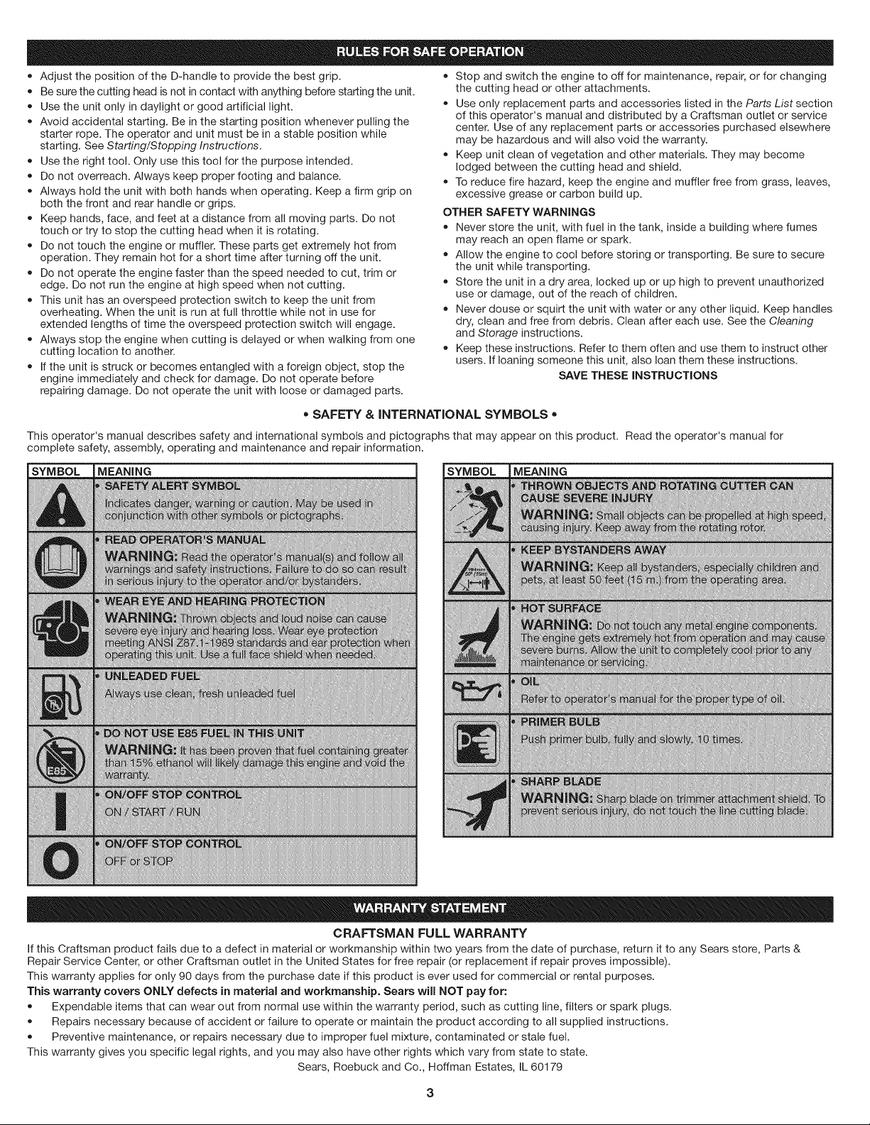
• SAFETY & INTERNATIONAL SYMBOLS •
This operator's manual describes safety and international symbols and pictographs that may appear on this product. Read the operator's manual for
complete safety, assembly, operating and maintenance and repair information.
SYMBOL MEANING SYMBOL MEANING
C RAFTSMAN FU LL WAR RANTY
If this Craftsman product fails due to a defect in material or workmanship within two years from the date of purchase, return it to any Sears store, Parts &
Repair Service Center, or other Craftsman outlet in the United States for free repair (or replacement if repair proves impossible).
This warranty applies for only 90 days from the purchase date if this product is ever used for commercial or rental purposes.
This warranty covers ONLY defects in material and workmanship. Sears will NOT pay for:
Expendable items that can wear out from normal use within the warranty period, such as cutting line, filters or spark plugs.
• Repairs necessary because of accident or failure to operate or maintain the product according to all supplied instructions.
• Preventive maintenance, or repairs necessary due to improper fuel mixture, contaminated or stale fuel.
This warranty gives you specific legal rights, and you may also have other rights which vary from state to state.
Sears, Roebuck and Co., Hoffman Estates, IL 60179
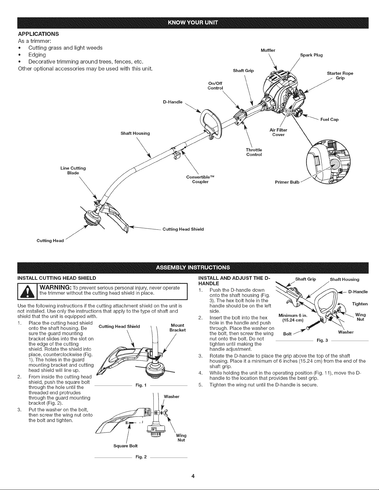
APPLICATIONS
Asatrimmer:
• Cuttinggrassandlightweeds Muffler
Edging \ Spark Plug
• Decorative trimming around trees, fences, etc. \ /
#
Other optional accessories may be used with this unit. Shaft Grin _-'_./,/
, _ ._'_._._\ Starter Hope
ContreOn'O",\ I Y .-4
°...°. \
Cutting Head Shield
Cutting Head
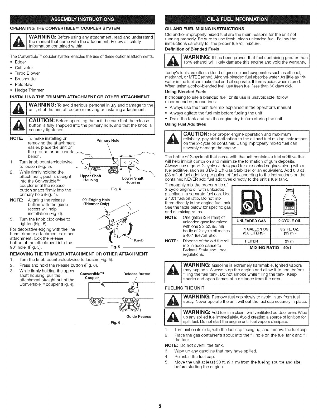
iNSTALL CUTTING HEAD SHIELD
_L_ ARNING: To prevent serious personal injury, never operate
the trimmer without the cutting head shield in place.
Use the following instructions if the cutting attachment shield on the unit is
not installed. Use only the instructions that apply to the type of shaft and
shield that the unit is equipped with.
1. Place the cutting head shield
onto the shaft housing. Be
sure the guard mounting
bracket slides into the slot on
the edge of the cutting
shield. Rotate the shield into
place, counterclockwise (Fig.
1). The holes in the guard
mounting bracket and cutting
head shield will line up.
2. From inside the cutting head
shield, push the square bolt
through the hole until the
threaded end protrudes
through the guard mounting
bracket (Fig. 2).
3. Put the washer on the bolt,
then screw the wing nut onto
the bolt and tighten.
Cutting Head Shield Mount
Bracket
Fig. f
Washer
Nut
Square Bolt
iNSTALL AND ADJUST THE D-
HANDLE
1. Push the D-handle down
onto the shaft housing (Fig.
3). The hex bolt hole in the
Shaft Grip Shaft Housing
side. Minimu in. wing
2. Insert the bolt into the hex
hole in the handle and push (15.24 era) _'_ Nut
through. Place the washer on
dO_ "\
the bolt, then screw the wing Bolt _ Washer
nut onto the bolt. Do not Fig. 3
tighten until making the
handle adjustment.
3. Rotate the D-handle to place the grip above the top of the shaft
housing. Place it a minimum of 6 inches (15.24 cm) from the end of the
shaft grip.
4. While holding the unit in the operating position (Fig. 11), move the D-
handle to the location that provides the best grip.
5. Tighten the wing nut until the D-handle is secure.
Fig. 2
OPERATING THE CONVERTIBLE TM COUPLER SYSTEM
_ WARNING: Before using any attachment, read and understand |
I
the manual that came with the attachment. Follow all safety
]
information contained within.
The Convertible TM coupler system enables the use of these optional attachments.
• Edger
Cultivator
Turbo Blower
Brushcutter
Pole Saw
Hedge Trimmer
INSTALLING THE TRIMMER ATTACHMENT OR OTHER ATTACHMENT
_j WARNING: To avoid serious personal injury and damage to the i
unit, shut the unit off before removing or installing attachment.
_ CAUTION: Before operating the unit, be sure that the release j
button is fully snapped into the primary hole, and that the knob is
securely tightened.
NOTE: To make installing or Primary Hole
removing the attachment
easier, place the unit on
the ground or on a work
bench.
1. Turn knob counterclockwise
to loosen (Fig. 5).
2. While firmly holding the
attachment, push it straight Upper Shaft Lower Shaft
into the Convertible TM Housing
Housing
coupler until the release
button snaps firmly into the Fig. 4
primary hole (Fig. 4).
NOTE: Aligning the release 90 ° Edging Hole
button with the guide (Trimmer Only)
recess will help
installation (Fig. 6).
3. Turn the knob clockwise to
tighten (Fig. 5).
For decorative edging with the line
head trimmer attachment or other
attachment, lock the release Knob
button of the attachment into the
90 ° hole (Fig. 5). Fig. 5
REMOVING THE TRIMMER ATTACHMENT OR OTHER ATTACHMENT
1. Turn the knob counterclockwise to loosen (Fig. 5).
2. Press and hold the release button (Fig. 6).
3.
While firmly holding the upper
shaft housing, pull the
attachment straight out of the
Convertible TM coupler (Fig. 4). --
Convertible TM Release Button
Coupler
Guide Recess
Fig. 6
OIL AND FUEL MIXING INSTRUCTIONS
Old and/or improperly mixed fuel are the main reasons for the unit not
running properly. Be sure to use fresh, clean unleaded fuel. Follow the
instructions carefully for the proper fuel/oil mixture.
Definition of Blended Fuels
L_WARNING: It has been proven that fuel containing greater than 1
15% ethanol will likely damage this engine and void the warranty, j
Today's fuels are often a blend of gasoline and oxygenates such as ethanol,
methanol, or MTBE (ether). Alcohol-blended fuel absorbs water. As little as 1%
water in the fuel can make fuel and oil separate. It forms acids when stored.
When using alcohol-blended fuel, use fresh fuel (less than 60 days old).
Using Blended Fuels
If choosing to use a blended fuel, or its use is unavoidable, follow
recommended precautions:
Always use the fresh fuel mix explained in the operator's manual
Always agitate the fuel mix before fueling the unit
Drain the tank and run the engine dry before storing the unit
Using Fuel Additives
_ CAUTION: For proper engine operation and maximum
reliability, pay strict attention to the oil and fuel mixing instructions
onthe2-cyceo contaner. Usng mproperymxedfue can |
severely damage the engine.
J
The bottle of 2-cycle oil that came with the unit contains a fuel additive that
will help inhibit corrosion and minimize the formation of gum deposits.
Always use a good 2-cycle oil designed for air-cooled engines along with a
fuel additive, such as STA-BIL® Gas Stabilizer or an equivalent. Add 0.8 oz.
(23 ml) of fuel additive per gallon of fuel according to the instructions on the
container. NEVER add fuel additives directly to the unit's fuel tank.
Thoroughly mix the proper ratio of
2-cycle engine oil with unleaded
gasoline in a separate fuel can. Use
a 40:1 fuel/oil ratio. Do not mix
them directly in the engine fuel tank.
See the table below for specific gas
and oil mixing ratios.
NOTE: One gallon (3.8 liters) of
unleaded gasoline mixed
with one 3.2 oz. (95 ml)
bottle of 2-cycle oil makes
a 40:1 fuel/oil ratio.
NOTE: Dispose of the old fuel/oil
mix in accordance to
Federal, State and Local
regulations.
__=
UNLEADED GAS 2 CYCLE OIL
1 GALLON US 3.2 FL. OZ.
(3.8 LITERS) (95 ml)
1 LITER 25 ml
MIXING RATIO - 40:1
WARNING: Gasoline is extremely flammable. Ignited vapors
may explode. Always stop the engine and allow it to cool before
filling the fuel tank. Do not smoke while filling the tank. Keep
sparks and open f ames at a d stance from the area.
FUELING THE UNIT
,t_ I WARNING: Remove fuel cap slowly to avoid injury from fuel
i
_spray. Never operate the un t w thout the rue cap secure y n p ace.
! ,_ I WARNING: Add fuel in a clean, well ventilated °utdoor area. Wipe I
up any spilled fuel immediately. Avoid creating a source of ignition for
spilt fuel. Do not start the engine until fuel vapors dissipate.
1. Turn unit on its side, with the fuel cap facing up, and remove the fuel cap.
2. Place the gas container's spout into the fill hole on the fuel tank and fill
the tank.
NOTE: Do not overfill the tank.
3. Wipe up any gasoline that may have spilled.
4. Reinstall the fuel cap.
5. Move the unit at least 30 ft. (9.1 m) from the fueling source and site
before starting the engine.
5
i
_ ARNING: Operate this unit only in a well-ventilated outdoor area.
Carbon monoxide exhaust fumes can be lethal in a confined area.
_ ARNING: Avoid accidental starting. Make sure to be in the
starting position when pulling the starter rope (Fig. 10). To avoid serious
injury, the operator and unit must be in a stable position while starting.
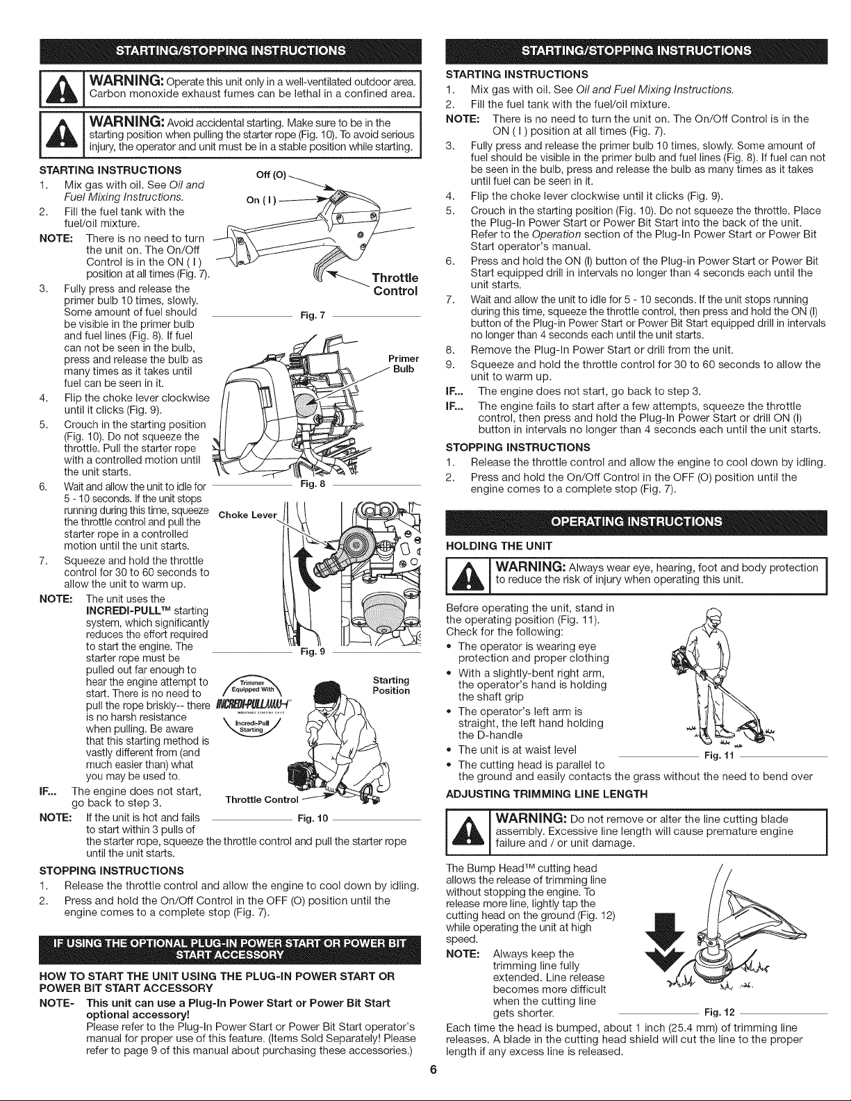
STARTING INSTRUCTIONS off (o)
1. Mix gas with oil. See Oil and
Fuel Mixing Instructions. On ( i ) _--_._-_-_-_-_-_-__
2. Fill the fuel tank with the
fuel/oil mixture.
NOTE: There is no need to turn
the unit on. The On/Off
Control is in the ON ( I )
position at all times (Fig. 7). _ _ Throttle
3. Fully press and release the Control
4.
5.
6.
7.
primer bulb 10 times, slowly.
Some amount of fuel should
be visible in the primer bulb
and fuel lines (Fig. 8). If fuel
NOTE:
Fig. 7
can not be seen in the bulb,
press and release the bulb as
many times as it takes until
fuel can be seen in it.
Flip the choke lever clockwise
until it clicks (Fig. 9).
Crouch in the starting position
(Fig. 10). Do not squeeze the
throttle. Pull the starter rope
with a controlled motion until
the unit starts.
Wait and allow the unit to idle for
5 - 10 seconds. If the unit stops
running during this time, squeeze Choke Lever
the throttle control and pull the
starter rope in a controlled
motion until the unit starts.
Squeeze and hold the throttle
control for 30 to 60 seconds to
allow the unit to warm up.
The unit uses the
INCREDI=PULL TM starting
system, which significantly
reduces the effort required
to start the engine. The
starter rope must be
pulled out far enough to
hear the engine attempt to
start. There is no need to / =qu,ppoo,,.\
pull the rope briskly-- there INC_BI'P#UJ/_J_t_
is no harsh resistance _ Nncmrli=PHN/Incredi.PuU
when pulling. Be aware
that this starting method is
vastly different from (and
much easier than) what
you may be used to.
IE.. The engine does not start,
go back to step 3. Throttle Control
NOTE: If the unit is hot and fails Fig. 10
to start within 3 pulls of
Fig. 8
Fig. 9
Starting
Position
the starter rope, squeeze the throttle control and pull the starter rope
until the unit starts.
STOPPING INSTRUCTIONS
1. Release the throttle control and allow the engine to cool down by idling.
2. Press and hold the On/Off Control in the OFF (O) position until the
engine comes to a complete stop (Fig. 7).
HOW TO START THE UNIT USING THE PLUG=IN POWER START OR
POWER BiT START ACCESSORY
NOTE= This unit can use a Plug-in Power Start or Power Bit Start
optional accessory!
Please refer to the Plug-In Power Start or Power Bit Start operator's
manual for proper use of this feature. (Items Sold Separately! Please
refer to page 9 of this manual about purchasing these accessories.)
STARTING INSTRUCTIONS
1. Mix gas with oil. See Oil and Fuel Mixing Instructions.
2. Fill the fuel tank with the fuel/oil mixture.
NOTE: There is no need to turn the unit on. The On/Off Control is in the
ON (I) position at all times (Fig. 7).
3. Fully press and release the primer bulb 10 times, slowly. Some amount of
fuel should be visible in the primer bulb and fuel lines (Fig. 8). If fuel can not
be seen in the bulb, press and release the bulb as many times as it takes
until fuel can be seen in it.
4. Flip the choke lever clockwise until it clicks (Fig. 9).
5. Crouch in the starting position (Fig. 10). Do not squeeze the throttle. Place
the Plug-In Power Start or Power Bit Start into the back of the unit.
Refer to the Operation section of the Plug-In Power Start or Power Bit
Start operator's manual.
6. Press and hold the ON (I) button of the Plug-in Power Start or Power Bit
Start equipped drill in intervals no longer than 4 seconds each until the
unit starts.
7. Wait and allow the unit to idle for 5 - 10 seconds. If the unit stops running
during this time, squeeze the throttle control, then press and hold the ON (I)
button of the Plug-in Power Start or Power Bit Start equipped drill in intervals
no longer than 4 seconds each until the unit starts.
8. Remove the Plug-In Power Start or drill from the unit.
9. Squeeze and hold the throttle control for 30 to 60 seconds to allow the
unit to warm up.
IF... The engine does not start, go back to step 3.
IF... The engine fails to start after a few attempts, squeeze the throttle
control, then press and hold the Plug-In Power Start or drill ON (I)
button in intervals no longer than 4 seconds each until the unit starts.
STOPPING INSTRUCTIONS
1. Release the throttle control and allow the engine to cool down by idling.
2. Press and hold the On/Off Control in the OFF (O) position until the
engine comes to a complete stop (Fig. 7).
HOLDING THE UNIT
_[_ ARNING: Always wear eye, hearing, foot and body protection
to reduce the risk of injury when operating this unit.
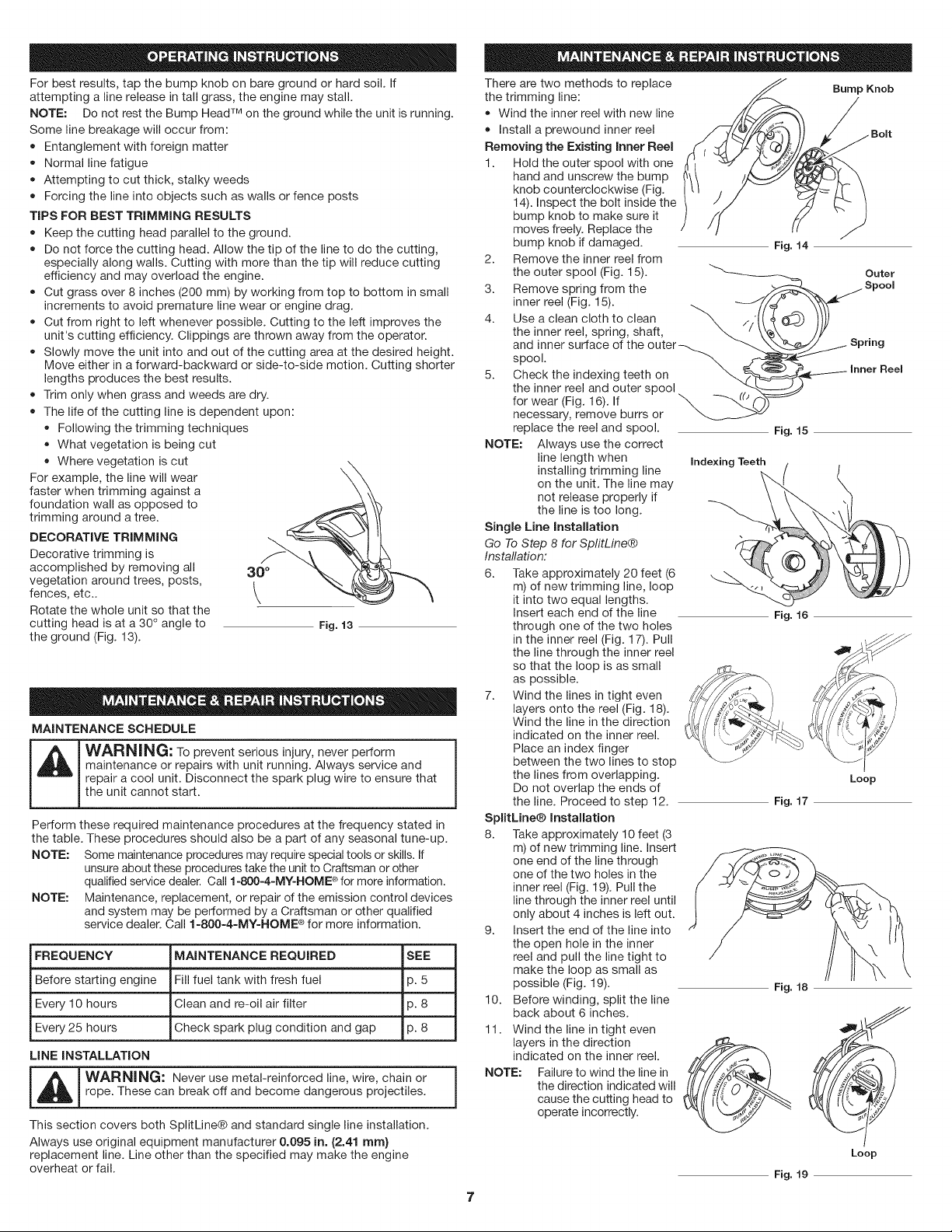
Before operating the unit, stand in
the operating position (Fig. 11).
Check for the following:
• The operator is wearing eye
protection and proper clothing
With a slightly-bent right arm,
the operator's hand is holding
the shaft grip
The operator's left arm is
straight, the left hand holding
the D-handle
• The unit is at waist level
• The cutting head is parallel to
\
Fig. 11
the ground and easily contacts the grass without the need to bend over
ADJUSTING TRiMMiNG LiNE LENGTH
_ WARNING" Do not remove or alter the line cutting blade
assembly. Excessive line length will cause premature engine
failure and / or unit damage.
The Bump Head TM cutting head
allows the release of trimming line
without stopping the engine. To
release more line, lightly tap the
cutting head on the ground (Fig. 12)
while operating the unit at high
speed.
NOTE: Always keep the
trimming line fully
extended. Line release
becomes more difficult *'_
when the cutting line
gets shorter. Fig. 12
Each time the head is bumped, about 1 inch (25.4 mm) of trimming line
releases. A blade in the cutting head shield will cut the line to the proper
length if any excess line is released.
Forbestresults,tapthebumpknobonbaregroundorhardsoil.If
attemptingalinereleaseintallgrass,theenginemaystall.
NOTE:DonotresttheBumpHeadTM on the ground while the unit is running.
Some line breakage will occur from:
• Entanglement with foreign matter
• Normal line fatigue
Attempting to cut thick, stalky weeds
Forcing the line into objects such as walls or fence posts
TIPS FOR BEST TRIMMING RESULTS
Keep the cutting head parallel to the ground.
Do not force the cutting head. Allow the tip of the line to do the cutting,
especially along walls. Cutting with more than the tip will reduce cutting
efficiency and may overload the engine.
Cut grass over 8 inches (200 mm) by working from top to bottom in small
increments to avoid premature line wear or engine drag.
Cut from right to left whenever possible. Cutting to the left improves the
unit's cutting efficiency. Clippings are thrown away from the operator.
Slowly move the unit into and out of the cutting area at the desired height.
Move either in a forward-backward or side-to-side motion. Cutting shorter
lengths produces the best results.
Trim only when grass and weeds are dry.
• The life of the cutting line is dependent upon:
Following the trimming techniques
What vegetation is being cut
Where vegetation is cut
For example, the line will wear
faster when trimming against a
foundation wall as opposed to
trimming around a tree.
DECORATIVE TRIMMING
Decorative trimming is
accomplished by removing all
vegetation around trees, posts,
fences, etc..
Rotate the whole unit so that the
cutting head is at a 30 ° angle to
the ground (Fig. 13).
30 °
Fig. 13
MAINTENANCE SCHEDULE
_ ARNING: To prevent serious injury, never perform
maintenance or repairs with unit running. Always service and
repair a cool unit. Disconnect the spark plug wire to ensure that
the unit cannot start.
Perform these required maintenance procedures at the frequency stated in
the table. These procedures should also be a part of any seasonal tune-up.
NOTE: Some maintenance procedures may require special tools or skills. If
unsure about these procedures take the unit to Craftsman or other
qualified service dealer. Call 1-800-4-MY-HOME ®for more information.
NOTE: Maintenance, replacement, or repair of the emission control devices
and system may be performed by a Craftsman or other qualified
service dealer. Call 1=800=4=MY=HOME ®for more information.
FREQUENCY MAINTENANCE REQUIRED SEE
Before starting engine Fill fuel tank with fresh fuel 3.5
Every 10 hours Clean and re-oil air filter 3.8
Every 25 hours Check spark plug condition and gap 3.8
LiNE INSTALLATION
_ ARNING: Never use metal-reinforced line, wire, chain or
rope. These can break off and become dangerous projectiles.
This section covers both SplitLine® and standard single line installation.
Always use original equipment manufacturer 0.095 in. (2.41 ram}
replacement line. Line other than the specified may make the engine
overheat or fail.
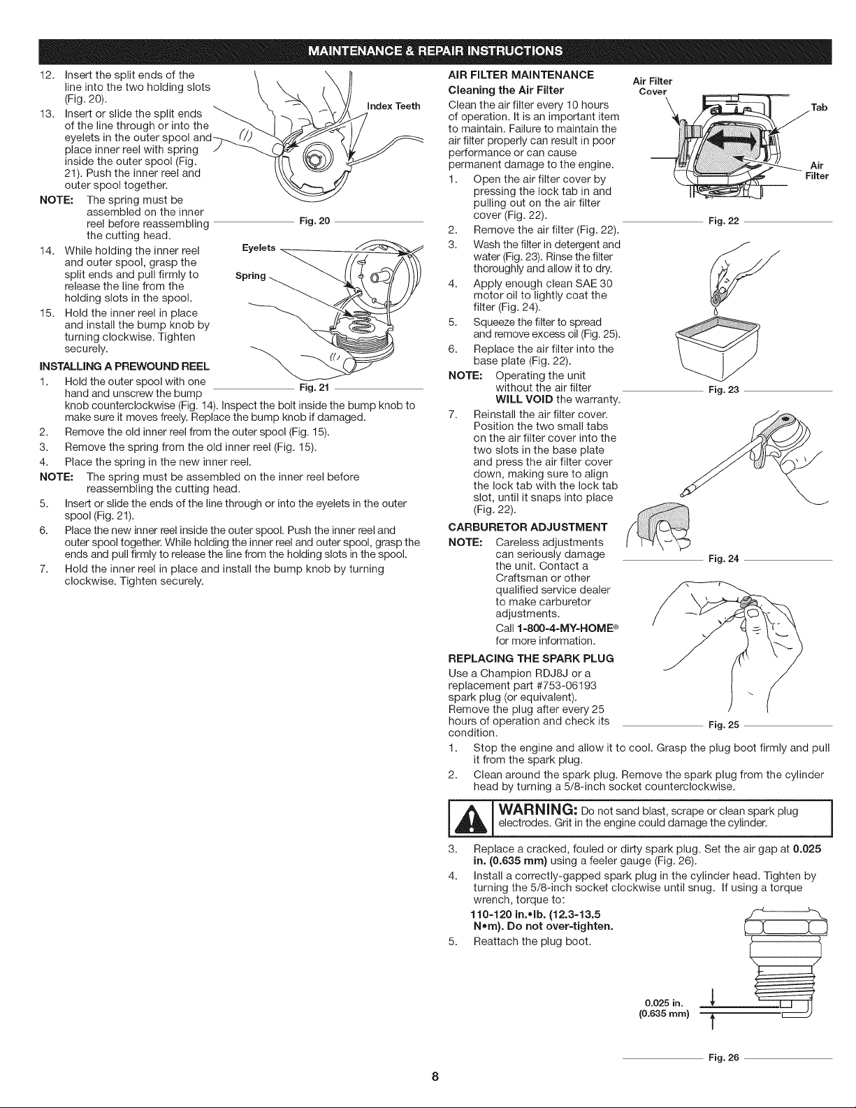
There are two methods to replace
the trimming line:
• Wind the inner reel with new line
Install a prewound inner reel
Removing the Existing Inner Reel
1. Hold the outer spool with one
hand and unscrew the bump
knob counterclockwise (Fig.
14). Inspect the bolt inside the
bump knob to make sure it
moves freely. Replace the
bump knob if damaged.
2. Remove the inner reel from
the outer spool (Fig. 15).
3. Remove spring from the
inner reel (Fig. 15).
4.
5.
_.
Use a clean cloth to clean \ ,.
the inner reel, spring, shaft,
and inner surface of the outer
spool. _
Check the indexing teeth on
the inner reel and outer spool
for wear (Fig. 16). If
necessary, remove burrs or
replace the reel and spool.
NOTE: Always use the correct
line length when
installing trimming line
on the unit. The line may
not release properly if
the line is too long.
Single Mne Installation
Go To Step 8 for SplitLine®
Instaflation:
6. Take approximately 20 feet (6
m) of new trimming line, loop
it into two equal lengths.
Insert each end of the line
through one of the two holes
in the inner reel (Fig. 17). Pull
the line through the inner reel
so that the loop is as small
as possible.
7. Wind the lines in tight even
layers onto the reel (Fig. 18).
Wind the line in the direction
indicated on the inner reel.
Place an index finger
between the two lines to stop
the lines from overlapping.
Do not overlap the ends of
the line. Proceed to step 12.
SplitLine® installation
8. Take approximately 10 feet (3
m) of new trimming line. Insert
one end of the line through
one of the two holes in the
inner reel (Fig. 19). Pull the
line through the inner reel until
only about 4 inches is left out.
9. Insert the end of the line into
the open hole in the inner
reel and pull the line tight to
make the loop as small as
possible (Fig. 19).
10. Before winding, split the line
Fig. 14
Bump Knob
Outer
Fig. 15
Indexing Teeth /
Fig. 16
Loop
Fig. 17
Fig. 18
back about 6 inches. , _./
11. Wind the line in tight even
layers in the direction __
indicated on the inner reel.
NOTE: Failure to wind the line in
the direction indicated will
cause the cutting head to
operate incorrectly.
Loop
Fig. 19
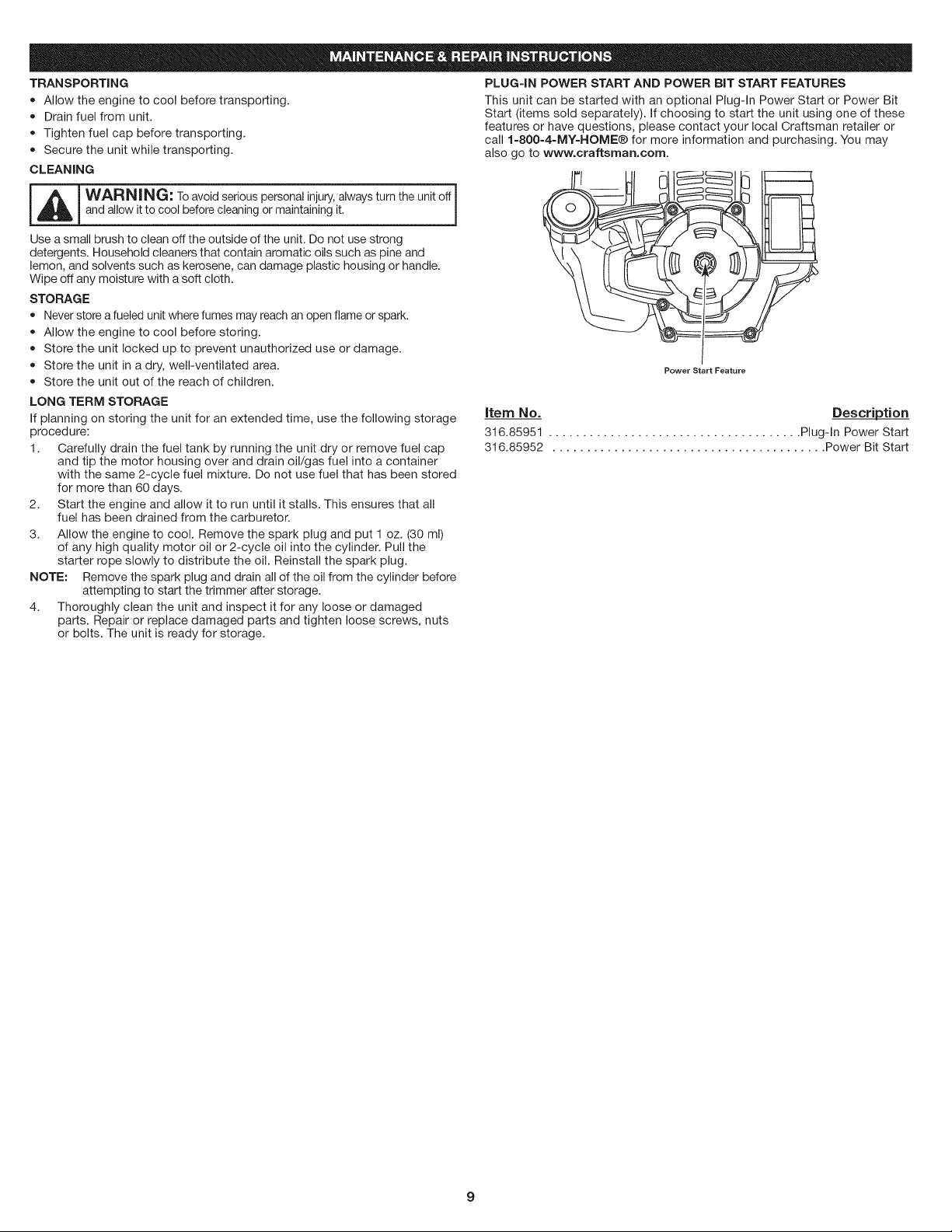
12. Insert the split ends of the
line into the two holding slots
(Fig. 20).
13. Insert or slide the split ends
of the line through or into the
eyelets in the outer spool
place inner reel with spring
inside the outer spool (Fig.
21). Push the inner reel and
outer spool together.
NOTE: The spring must be
assembled on the inner
reel before reassembling
the cutting head.
14. While holding the inner reel
and outer spool, grasp the
split ends and pull firmly to
release the line from the
holding slots in the spool.
15. Hold the inner reel in place
and install the bump knob by
turning clockwise. Tighten
securely.
INSTALLING A PREWOUND REEL
1. Hold the outer spool with one
hand and unscrew the bump
Index Teeth
Fig. 20
Eyelets
Spring
Fig. 21
knob counterclockwise (Fig. 14). Inspect the bolt inside the bump knob to
make sure it moves freely. Replace the bump knob if damaged.
2. Remove the old inner reel from the outer spool (Fig. 15).
3. Remove the spring from the old inner reel (Fig. 15).
4. Place the spring in the new inner reel.
NOTE: The spring must be assembled on the inner reel before
reassembling the cutting head.
5. Insert or slide the ends of the line through or into the eyelets in the outer
spool (Fig. 21).
6. Place the new inner reel inside the outer spool. Push the inner reel and
outer spool together. While holding the inner reel and outer spool, grasp the
ends and pull firmly to release the line from the holding slots in the spool.
7. Hold the inner reel in place and install the bump knob by turning
clockwise. Tighten securely.
AiR FILTER MAINTENANCE
Cleaning the Air Filter
Clean the air filter every 10 hours
of operation. It is an important item
to maintain. Failure to maintain the
air filter properly can result in poor
performance or can cause
permanent damage to the engine.
1. Open the air filter cover by
pressing the lock tab in and
pulling out on the air filter
cover (Fig. 22).
2. Remove the air filter (Fig. 22).
3. Wash the filter in detergent and
water (Fig. 23). Rinse the filter
thoroughly and allow it to dry.
4. Apply enough clean SAE 30
motor oil to lightly coat the
filter (Fig. 24).
5. Squeeze the filter to spread
and remove excess oil (Fig. 25).
6. Replace the air filter into the
base plate (Fig. 22).
NOTE: Operating the unit
without the air filter
WiLL VOiD the warranty.
7. Reinstall the air filter cover.
Position the two small tabs
on the air filter cover into the
two slots in the base plate
and press the air filter cover
down, making sure to align
the lock tab with the lock tab
slot, until it snaps into place
(Fig. 22).
CARBURETOR ADJUSTMENT
NOTE: Careless adjustments
can seriously damage
the unit. Contact a
Craftsman or other
qualified service dealer
to make carburetor
adjustments.
Call 1-800=4=MY-HOME ®
for more information.
Air Filter
Cover
Fig. 22
<
6
Fig. 23
Fig. 24
REPLACING THE SPARK PLUG
Use a Champion RDJ8J or a
replacement part #753-06193
spark plug (or equivalent).
Remove the plug after every 25
hours of operation and check its Fig. 25
condition.
1. Stop the engine and allow it to cool. Grasp the plug boot firmly and pull
it from the spark plug.
2. Clean around the spark plug. Remove the spark plug from the cylinder
head by turning a 5/8-inch socket counterclockwise.
-- 1___ ARNING: Do not sand blast, scrape or clean spark plug
electrodes. Grit in the engine could damage the cylinder.
3. Replace a cracked, fouled or dirty spark plug. Set the air gap at 0.025
in. (0.635 rnrn} using a feeler gauge (Fig. 26).
4. Install a correctly-gapped spark plug in the cylinder head. Tighten by
turning the 5/8-inch socket clockwise until snug. If using a torque
wrench, torque to:
110-120 in.olb. (12.3-13.5
Norn}. Do not over-tighten.
5. Reattach the plug boot.
0.025 in.
(0.635 ram) f
8
Fig. 26
TRANSPORTING
• Allow the engine to cool before transporting.
Drain fuel from unit.
Tighten fuel cap before transporting.
Secure the unit while transporting.
CLEANING
PLUG=IN POWER START AND POWER BIT START FEATURES
This unit can be started with an optional Plug-In Power Start or Power Bit
Start (items sold separately). If choosing to start the unit using one of these
features or have questions, please contact your local Craftsman retailer or
call 1-800-4=MY-HOME® for more information and purchasing. You may
also go to www.craftsman.com.
-- i
WARNI NG: Toavoidserious personalinjury,alwaysturn the unit off
and allow it to cool before cleaning or maintaining it.
Use a small brush to clean offthe outside of the unit. Do not use strong
detergents. Household cleaners that contain aromatic oils such as pine and
lemon, and solvents such as kerosene, can damage plastic housing or handle.
Wipe off any moisture with a soft cloth.
STORAGE
Never store a fueled unit where fumes may reach an open flame or spark.
Allow the engine to cool before storing.
Store the unit locked up to prevent unauthorized use or damage.
Store the unit in a dry, well-ventilated area.
Store the unit out of the reach of children.
Power Start Feature
LONG TERM STORAGE
If planning on storing the unit for an extended time, use the following storage
procedure:
1. Carefully drain the fuel tank by running the unit dry or remove fuel cap
and tip the motor housing over and drain oil/gas fuel into a container
with the same 2-cycle fuel mixture. Do not use fuel that has been stored
for more than 60 days.
2. Start the engine and allow it to run until it stalls. This ensures that all
fuel has been drained from the carburetor.
3. Allow the engine to cool. Remove the spark plug and put 1 oz. (30 ml)
of any high quality motor oil or 2-cycle oil into the cylinder. Pull the
starter rope slowly to distribute the oil. Reinstall the spark plug.
NOTE: Remove the spark plug and drain all of the oil from the cylinder before
attempting to start the trimmer after storage.
4. Thoroughly clean the unit and inspect it for any loose or damaged
parts. Repair or replace damaged parts and tighten loose screws, nuts
or bolts. The unit is ready for storage.
item No. Description
316.85951 ..................................... Plug-In Power Start
316.85952 ........................................ Power Bit Start

Emptyfueltank
Engineisflooded
Fouledsparkplug
Airfilterisplugged
Impropercarburetoradjustment
Oldorimproperlymixedfuel
Dirtyairfilter
Oldorimproperlymixedfuel
Fouledsparkplug
Engineoverspeedprotectionengaged
Cuttingheadboundwithgrass
Innerreelboundup
Linewelded
PROBLEM SOLUTION
Fill fuel tank with properly mixed fuel
Pull the starter rope while holding the throttle control
Replace the spark plug
Replace or clean the air filter
Take to a Craftsman or other qualified service dealer for adjustment
Drain fuel tank and add fresh fuel mixture
Clean or replace the air filter
Drain fuel tank and add fresh fuel mixture
Replace the spark plug
Allow the engine to cool down for 10 minutes before restarting
Stop the engine and clean cutting head
Rewind the inner reel
Disassemble, remove the welded section and rewind
Not enough line is exposed Push the bump knob and pull out line until 4 inches (102 mm) of line is
outside of the cutting head
Oil, cleaner or lubricant in cutting head Clean and thoroughly dry the cutting head
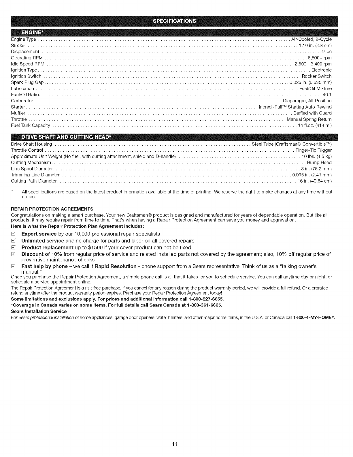
EngineType................................................................................................... Air-Cooled,2-Cycle
Stroke........................................................................................................... 1.10in.(2.8cm)
Displacement............................................................................................................. 27cc
OperatingRPM....................................................................................................... 6,800+rpm
IdleSpeedRPM................................................................................................. 2,800-3,400rpm
IgnitionType........................................................................................................... Electronic
IgnitionSwitch..................................................................................................... RockerSwitch
SparkPlugGap................................................................................................ 0.025in.(0.635mm)
Lubrication....................................................................................................... Fuel/OilMixture
Fuel/OilRatio............................................................................................................... 40:1
Carburetor................................................................................................. Diaphragm,All-Position
Starter........................................................................................... Incredi-PullTM Starting Auto Rewind
Muffler ........................................................................................................ Baffled with Guard
Throttle ..................................................................................................... Manual Spring Return
Fuel Tank Capacity ................................................................................................ 14 fl.oz. (414 ml)
Drive Shaft Housing ............................................................................. Steel Tube (Craftsman@ Convertible TM)
Throttle Control .................................................................................................. Finger-Tip Trigger
Approximate Unit Weight (No fuel, with cutting attachment, shield and D-handle) ................................................. 10 Ibs. (4.5 kg)
Cutting Mechanism .................................................................................................... Bump Head
Line Spool Diameter ................................................................................................. 3 in. (76.2 mm)
Trimming Line Diameter .......................................................................................... 0.095 in. (2.41 mm)
Cutting Path Diameter .............................................................................................. 16 in. (40.64 cm)
* All specifications are based on the latest product information available at the time of printing. We reserve the right to make changes at any time without
notice.
REPAIR PROTECTION AGREEMENTS
Congratulations on making a smart purchase. Your new Craftsman@ product is designed and manufactured for years of dependable operation. But like all
products, it may require repair from time to time. That's when having a Repair Protection Agreement can save you money and aggravation.
Here is what the Repair Protection Plan Agreement includes:
[] Expert service by our 10,000 professional repair specialists
[] Unlimited service and no charge for parts and labor on all covered repairs
[] Product replacement up to $1500 if your cover product can not be fixed
[] Discount of 10% from regular price of service and related installed parts not covered by the agreement; also, 10% off regular price of
preventive maintenance checks
[] Fast help by phone - we call it Rapid Resolution - phone support from a Sears representative. Think of us as a "talking owner's
manual."
Once you purchase the Repair Protection Agreement, a simple phone call is all that it takes for you to schedule service. You can call anytime day or night, or
schedule a service appointment online.
The Repair Protection Agreement is a risk-free purchase. If you cancel for any reason during the product warranty period, we will provide a full refund. Or a prorated
refund anytime after the product warranty period expires. Purchase your Repair Protection Agreement today!
Some limitations and exclusions apply. For prices and additional information call 1-800-827-6655.
*Coverage in Canada varies on some items. For full details call Sears Canada at 1-800-361-6665.
Sears installation Service
For Sears professional installation of home appliances, garage door openers, water heaters, and other major home items, in the U.S.A. or Canada call 1-800-4-MY-HOME ®.
11

12
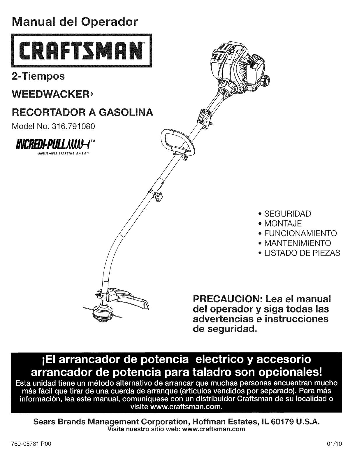
Manual del Operador
®
2-Tiempos
WEEDWACKER_
RECORTADOR A GASOLINA
Model No. 316.791080
_EUEVABLE STARTIN6 E _ _ E '_
o SEGURIDAD
MONTAJE
FUNCIONAMIENTO
MANTENIMIENTO
LISTADO DE PIEZAS
PRECAUCION: Lea el manual
del operador y siga todas las
advertencias e instrucciones
de seguridad.
Sears Brands Management Corporation, Hoffman Estates, IL 60179 U.S.A.
Visite nuestro sitio web: www.craftsman.com
769-05781 P00 01/10
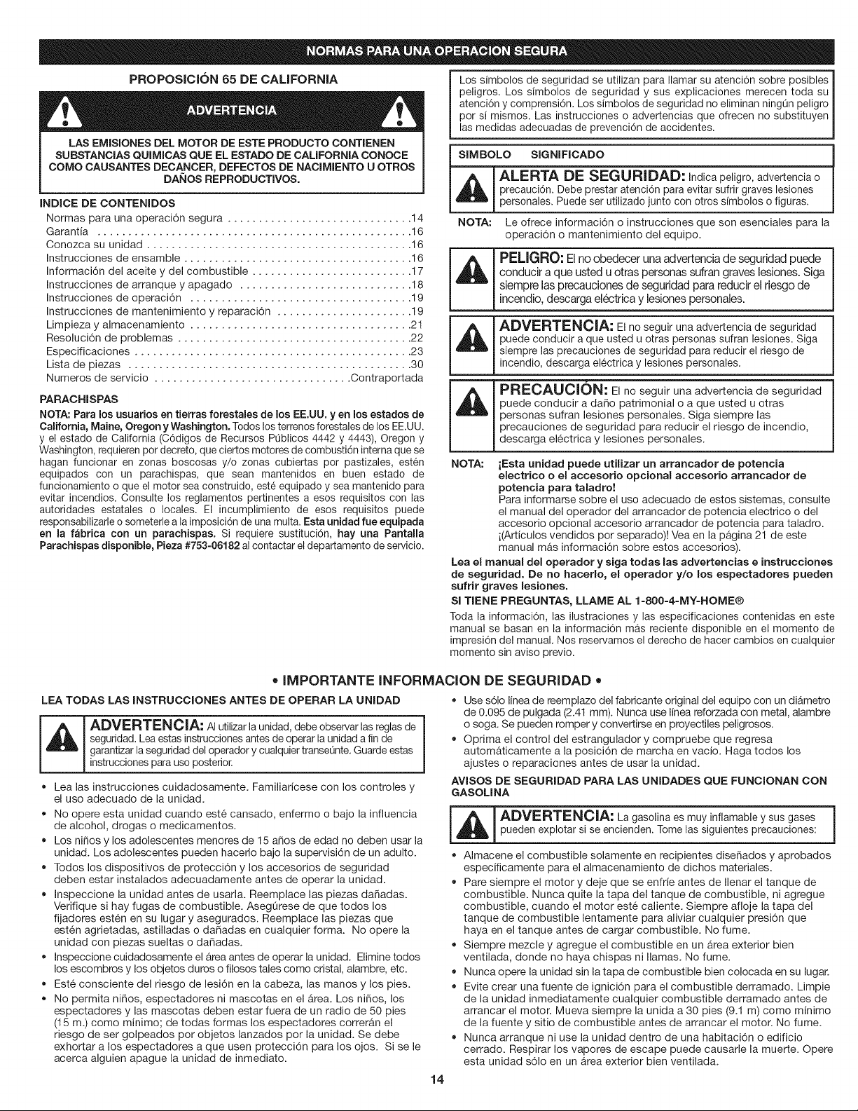
PROPOSICION 65 DE CALiFORNiA
LAS EMISIONES DEL MOTOR DE ESTE PRODUCTO CONTIENEN
SUBSTANCIAS QUIMICAS QUE EL ESTADO DE CALIFORNIA CONOCE
COMO CAUSANTES DECANCER, DEFECTOS DE NACIMIENTO U OTROS
DAI_OS REPRODUCTIVOS.
INDICE DE CONTENIDOS
Normas para una operaci6n segura .............................. 14
Garantia ................................................... 16
Conozca su unidad ........................................... 16
Instrucciones de ensamble ..................................... 16
Informaci6n del aceite y del combustible .......................... 17
Instrucciones de arranque y apagado ............................ 18
Instrucciones de operaci6n .................................... 19
Instrucciones de mantenimiento y reparaci6n ...................... 19
Limpieza y almacenamiento .................................... 21
Resoluci6n de problemas ...................................... 22
Especificaciones ............................................. 23
Lista de piezas .............................................. 30
Numeros de servicio ................................ Contraportada
PARACHISPAS
NOTA: Para los usuarios en tierras forestales de los EE.UU. yen los estados de
California, Maine, Oregon y Washington. Todos los terrenos forestales de los EE.UU.
y el estado de California (C6digos de Recursos PQblicos 4442 y 4443), Oregon y
Washington, requieren por decreto, que ciertos motores de combusti6n intema que se
hagan funcionar en zonas boscosas y/o zonas cubiertas por pastizales, esten
equipados con un parachispas, que sean mantenidos en buen estado de
funcionamiento o que el motor sea construido, este equipado y sea mantenido para
evitar incendios. Consulte los reglamentos pertinentes a esos requisitos con las
autoridades estatales o locales. El incumplimiento de esos requisitos puede
responsabilizarle o someterle a la imposici6n de una multa. Esta unidad rue equipada
en la fabrica con un parachispas. Si requiere sustituci6n, hay una Pantalla
Parachispas disponible, Pieza #753-06182 al contactar el departamento de servicio.
Los simbolos de seguridad se utilizan para Ilamar su atenci6n sobre posibles
peligros. Los simbolos de seguridad y sus explicaciones merecen toda su
atenci6n y comprensi6n. Los simbolos de seguridad no eliminan ningQn peligro
por si mismos. Las instrucciones o advertencias que ofrecen no substituyen
las medidas adecuadas de prevenci6n de accidentes.
SIMBOLO SIGNIFICADO
ALERTA DE SEGURIDAD: Indica peligro, advertencia o
precauci6n. Debe prestar atenci6n para evitar sufrir graves lesiones
personales. Puede ser utilizado junto con otros simbolos o figuras.
NOTA: Le ofrece informaci6n o instrucciones que son esenciales para la
operaci6n o mantenimiento del equipo.
PELIGRO: El no obedecer una advertencia de seguridad puede
conducir a que usted u otras personas sufran graves lesiones. Siga
siempre las precauciones de seguridad para reducir el riesgo de
incendio, descarga electrica y lesiones personales.
ADVERTENCIA: El no seguir una advertencia de seguridad
puede conducir a que usted u otras personas sufran lesiones. Siga
siempre las precauciones de seguridad para reducir el riesgo de
incendio, descarga el6ctrica y lesiones personales.
PRECAUCION: El no seguir una advertencia de seguridad
puede conducir a dafio patrimonial o a que usted u otras
personas sufran lesiones personales. Siga siempre las
precauciones de seguridad para reducir el riesgo de incendio,
descarga el6ctrica y lesiones personales.
NOTA: iEsta unidad puede utilizar un arrancador de potencia
electrico o el accesorio optional accesorio arrancador de
potencia para taladro!
Para informarse sobre el uso adecuado de estos sistemas, consulte
el manual del operador del arrancador de potencia electrico o del
accesorio opcional accesorio arrancador de potencia para taladro.
i(Articulos vendidos por separado)! Vea en la p&gina 21 de este
manual mAs informaci6n sobre estos accesorios).
Lea el manual del operador y siga todas las advertencias e instrucciones
de seguridad. De no hacerlo, el operador y/o los espectadores pueden
sufrir graves lesiones.
Sl TIENE PREGUNTAS, LLAME AL 1=800-4=MY=HOME®
Toda la informaci6n, las ilustraciones y las especificaciones contenidas en este
manual se basan en la informaci6n mAs reciente disponible en el momento de
impresi6n del manual. Nos reservamos el derecho de hacer cambios en cualquier
momento sin aviso previo.
• IMPORTANTE INFORMACION DE SEGURiDAD •
LEA TODAS LAS INSTRUCCIONES ANTES DE OPERAR LA UNIDAD
ADVERTENCIA: AI utilizar la unidad, debe observar las reglasde
seguridad. Lea estas instrucciones antes de operar la unidad a fin de
garantizar la seguridad del operador y cualquier transeQnte.Guarde estas
instrucciones para uso posterior.
• Lea las instrucciones cuidadosamente. Familiaricese con los controles y
el uso adecuado de la unidad.
• No opere esta unidad cuando est6 cansado, enfermo o bajo la influencia
de alcohol, drogas o medicamentos.
• Los niSos y los adolescentes menores de 15 aSos de edad no deben usar la
unidad. Los adolescentes pueden hacerlo bajo la supervisi6n de un adulto.
• Todos los dispositivos de protecci6n y los accesorios de seguridad
deben estar instalados adecuadamente antes de operar la unidad.
Inspeccione la unidad antes de usarla. Reemplace las piezas dafiadas.
Verifique si hay fugas de combustible. AsegQrese de que todos los
fijadores est6n en su lugar y asegurados. Reemplace las piezas que
est6n agrietadas, astilladas o dafiadas en cualquier forma. No opere la
unidad con piezas sueltas o dafiadas.
• Inspeccione cuidadosamente el Area antes de operar la unidad. Elimine todos
los escombros y los objetos duros o filosos tales como cristal, alambre, etc.
Est6 consciente del riesgo de lesi6n en la cabeza, las manos y los pies.
No permita nifios, espectadores ni mascotas en el Area. Los nifios, los
espectadores y las mascotas deben estar fuera de un radio de 50 pies
(15 m.) como minimo; de todas formas los espectadores correran el
riesgo de ser golpeados por objetos lanzados pot la unidad. Se debe
exhortar a los espectadores a que usen protecci6n para los ojos. Si se le
acerca alguien apague la unidad de inmediato.
Use s61o linea de reemplazo del fabricante original del equipo con un diAmetro
de 0.095 de pulgada (2.41 mm). Nunca use linea reforzada con metal, alambre
o soga. Se pueden romper y convertirse en proyectiles peligrosos.
Optima el control del estrangulador y compruebe que regresa
automaticamente a la posici6n de marcha en vacio. Haga todos los
ajustes o reparaciones antes de usar la unidad.
AVISOS DE SEGURIDAD PARA LAS UNIDADES QUE FUNCIONAN CON
GASOLINA
[_ ADVERTENCIA: La gasolina es muy inflamable y sus gases |
pueden explotar si se encienden. Tome las siguientes precauciones:
I
AImacene el combustible solamente en recipientes disefiados y aprobados
especificamente para el almacenamiento de dichos materiales.
Pare siempre el motor y deje que se enfrie antes de Ilenar el tanque de
combustible. Nunca quite la tapa del tanque de combustible, ni agregue
combustible, cuando el motor est6 caliente. Siempre afloje la tapa del
tanque de combustible lentamente para aliviar cualquier presi6n que
haya en el tanque antes de cargar combustible. No fume.
Siempre mezcle y agregue el combustible en un Area exterior bien
ventilada, donde no haya chispas ni llamas. No fume.
• Nunca opere la unidad sin la tapa de combustible bien colocada en su lugar.
Evite crear una fuente de ignici6n para el combustible derramado. Limpie
de la unidad inmediatamente cualquier combustible derramado antes de
arrancar el motor. Mueva siempre la unida a 30 pies (9.1 m) como minimo
de la fuente y sitio de combustible antes de arrancar el motor. No fume.
• Nunca arranque ni use la unidad dentro de una habitaci6n o edificio
cerrado. Respirar los vapores de escape puede causarle la muerte. Opere
esta unidad s61o en un Area exterior bien ventilada.
14
CUANDO EST': OPERANDO
• Nunca arranque ni opere la unidad dentro de un cuarto o edificio cerrado.
Respirar los vapores del escape puede ser fatal. Siempre opere esta
unidad solamente en un Area exterior bien ventilada.
Use galas protectoras que cumplan con la norma Z87.1-1989 de ANSI y
tengan la marca que Io indica. Use protecci6n para la oreja/audici6n
cuando opere esta unidad. Use mascara facial o para polvo si la
operaci6n produce mucho polvo.
Use pantalones largos fuertes, botas, guantes y camisa de mangas
largas. No use ropa holgada, joyas, pantalones cortes, sandalias, ni est6
descalzo. AsegOrese el cabello per encima del nivel de los hombros.
• El protector del accesorio de corte debe estar siempre colocado cuando
se utilice la unidad como recortador. No opere la unidad sin ambas lineas
de corte extendidas y con la linea adecuada instalada. No extienda la
linea de corte mas alia de la Iongitud del protector.
AsegOrese de que el accesorio de corte no estA en contacto con ningOn
objeto antes de arrancar la unidad.
Ajuste la posici6n de la D-manija para facilitar el mejor agarre.
El accesorio de corte puede estar girando durante los ajustes del
carburador. Use ropa que Io proteja y cumpla con todas las instrucciones
de seguridad para prevenir graves lesiones personales.
• Use la unidad solamente de dia o con buena luz artificial.
Evite arranques accidentales. Est6 en la posici6n de arranque cada vez que
hale la cuerda de arranque. Eloperador y la unidad deben estar en una
posici6n estable al arrancar. Consulte las Instrucciones de Arranque/Parada.
Use la herramienta correcta. Use esta herramienta solamente para el
prop6sito para el cual rue disefiada.
No se estire demasiado. Mantenga siempre la base de apoyo y equilibrio
adecuados.
Sostenga siempre la unidad con ambas manos cuando la opere. Mantenga
un agarre firme sobre ambas manijas.
Mantenga las manos, la cara y los pies alejados de todas las partes en
movimiento. No toque nitrate de parar el accesorio de corte cuando est6
girando.
No toque el motor, la caja de engranajes ni el silenciador. Estas piezas
estan muy calientes durante la operaci6n, incluso despues de que se
apaga la unidad.
• No opere el motor a m&s velocidad de la necesaria para cortar, recortar o
recortar bordes. No haga funcionar el motor a alta velocidad cuando no
est6 cortando.
Esta unidad tiene un interrupter de la protecci6n de la velocidad excesiva
para guardar la unidad del recalentamiento. Cuando la unidad se funciona
con en la valvula reguladora Ilena mientras que es parada para las
longitudes del tiempo extendidas que el interrupter de la protecci6n de la
velocidad excesiva dedicar&.
Pare siempre el motor cuando deje de cortar o cuando est6 caminando
de un lugar de corte hacia otro.
Si golpea o se enreda con un objeto extrafio, pare el motor
inmediatamente y verifique si ha habido algOn dafio. No Io opere antes de
reparar el dafio. No opere la unidad con piezas sueltas o dafiadas.
Pare la unidad, apague el motor y desconecte la bujia para mantenimiento
o reparaci6n.
Utilice Onicamente piezas de repuesto y los accesorios que figuran en la
secci6n de la Lista de Piezas de este manual del operador y distribuidos
por una toma de Craftsman o centro de servicio. El uso de cualquier pieza
de repuesto o accesorios comprados en otro lugar puede ser peligroso y
anulara la garantia.
Mantenga la unidad limpia de vegetaci6n y otros materiales. Pudieran
quedar obstruidas entre el accesorio de corte y el protector.
Para reducir el peligro de incendio, mantenga el motor y el silenciador
libre de hierba, hojas, exceso de grasa o acumulaci6n de carb6n.
OTROS AVlSOS DE SEGURIDAD
• Nunca almacene una unidad con combustible dentro de un edificio en el
cual los vapores puedan Ilegar a una llama expuesta o una chispa.
Deje que el motor se enfrie antes de almacenarlo o transportarlo.
AsegOrese de fijar bien la unidad mientras la transporta.
Almacene la unidad en un area seca y cerrada, o en un lugar alto para evitar
use no autorizado o da_os. Mant6ngala alejada del alcance de los nifios.
Nunca rocie ni chorree la unidad con agua ni ningOn otro liquido.
Mantenga las manijas secas, limpias y libres de escombros. Limpiela
despues de usarla, vea las instrucciones de Limpieza y Almacenamiento.
Conserve estas instrucciones. ConsOltelas con frecuencia y Oselas para
instruir a otros usuarios. Si le presta esta unidad a alguien, pr6stele
tambien estas instrucciones.
CONSERVE ESTAS INSTRUCCIONES
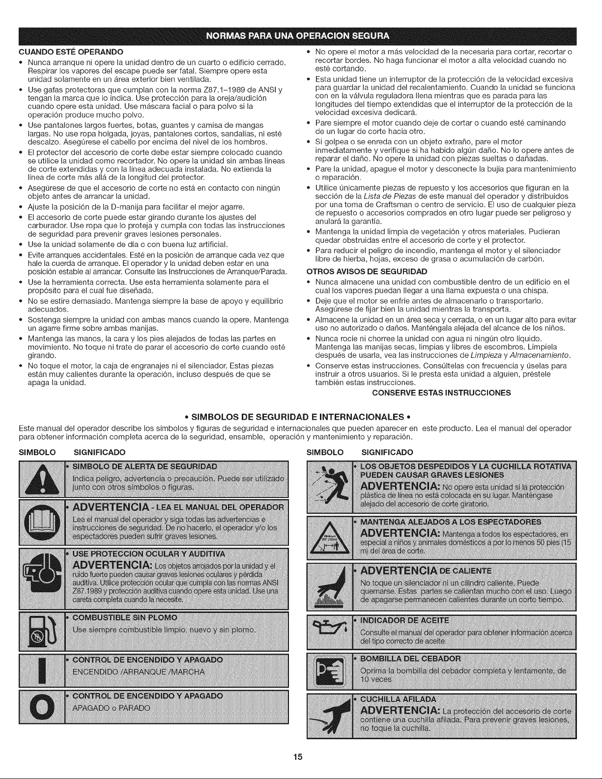
• SIMBOLOS DE SEGURIDAD E INTERNACIONALES •
Este manual del operador describe los simbolos y figuras de seguridad e internacionales que pueden aparecer en este producto. Lea el manual del operador
para obtener informaci6n completa acerca de la seguridad, ensamble, operaci6n y mantenimiento y reparaci6n.
SIMBOLO SIGNIFICADO SIMBOLO SIGNIFICADO
Fii
15
GARANTJA TOTAL DE CRAFTSMAN
Si este producto de Craftsman Professional falla debido a un defecto en el material o en la mane de obra dentro de un periodo de tres aSos a partir de la fecha
de compra, devuelvalo a cualquier tienda o Centre de Servicio de Piezas y Reparaciones Sears u otro establecimiento de Craftsman en los Estados Unidos
para que sea reparado sin costo alguno (o ser reemplazado si resulta imposible repararlo).
Esta garantia se aplica solamente durante 90 dias si este producto en algOn memento se utiliza para fines comerciales o de alquiler.
Esta garantia abarca SOLAMENTE los defectos en el material o en la mane de obra. Sears NO pagar_:
• Los articulos consumibles que se desgasten debido al use normal dentro del periodo de garantia.
• Las reparaciones necesarias debidas a accidente asi come per no operar o no mantener el equipo de acuerdo con todas las instrucciones provistas.
• Mantenimiento preventive, o las reparaciones necesarias debido a mezcla incorrecta de combustible, combustible contaminado o viejo.
Esta garantia le concede a usted derechos legales especificos, y usted pudiera tener otros derechos que varian de un estado a otro.
Sears, Roebuck and Co., Hoffman Estates, IL 60179
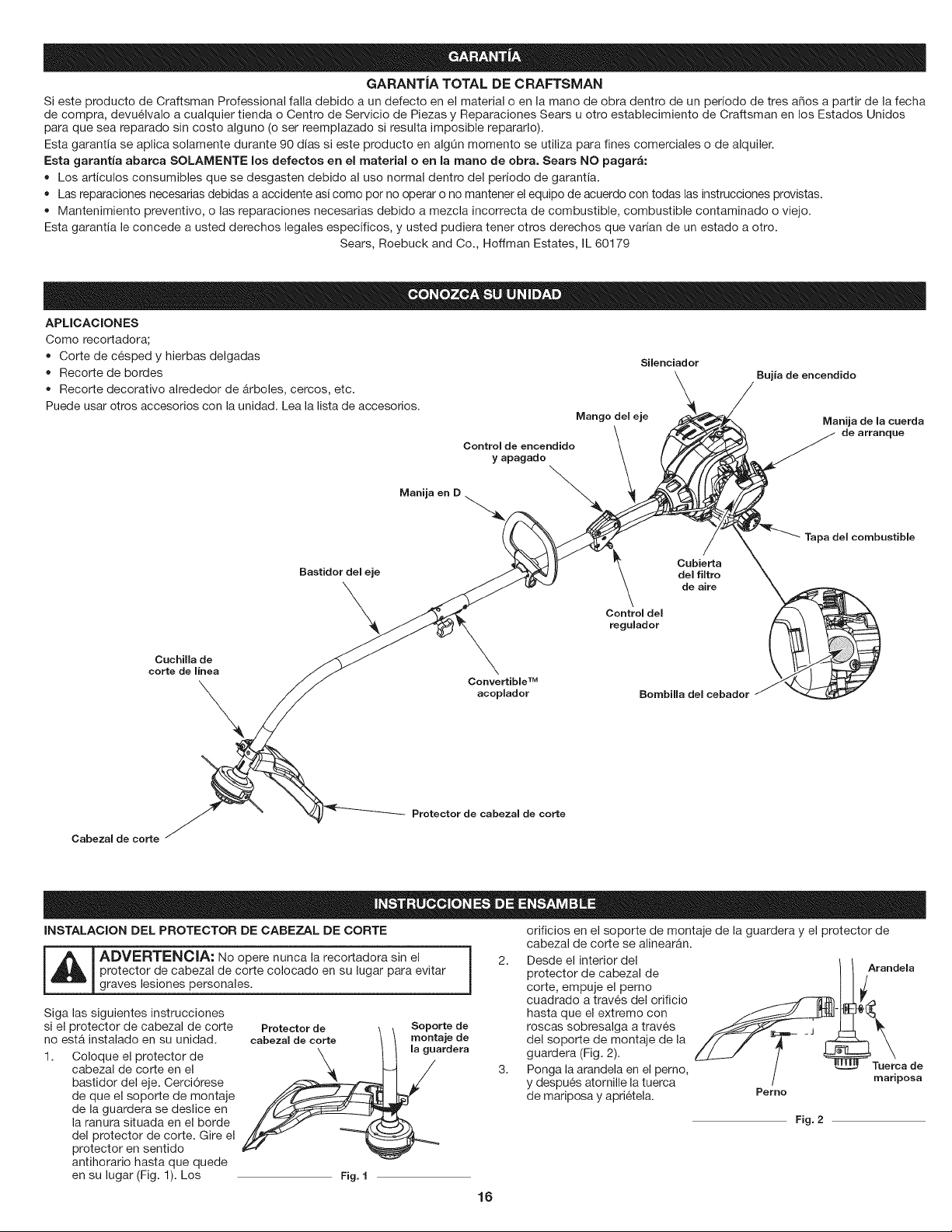
APLICACIONES
Come recortadora;
• Corte de cesped y hierbas delgadas Silenciador
• Recorte de bordes
\ Bujia
de encendido
• Recorte decorative alrededor de _rboles, cercos, etc. \ /
/
Puede usar otros accesorios con la unidad. Lea la lista de accesorios.., . _,/_,__ /
Mango
ueleje _\ Manija de lacuerda
\ _-------_._'_ / de arranque
Control de encendido \ f __/') /
cCr C" i :a ,cembost,b,e
.... .em.,,,o.e,ce.o.erJ
Protector de cabezal de corte
Cabezal de corte
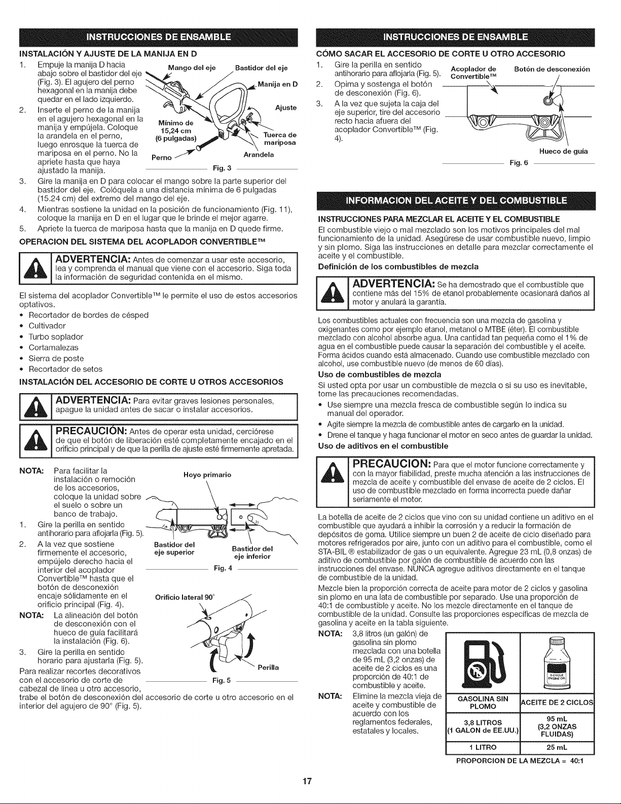
INSTALACION DEL PROTECTOR DE CABEZAL DE CORTE orificios en el soporte de montaje de la guardera y el protector de
_ DVERTENClA: No opere nunca la recortadora sin el
protector de cabezal de corte colocado en su lugar para evitar
graves lesiones personales.
Siga las siguientes instrucciones
si el protector de cabezal de corte
no est& instalado en su unidad.
1. Coloque el protector de
cabezal de corte en el
bastidor del eje. Cerci6rese
de que el soporte de montaje
de la guardera se deslice en
la ranura situada en el borde
del protector de corte. Gire el
protector en sentido
antihorario hasta que quede
en su lugar (Fig. 1). Los
Protector de Soporte de
cabezal de corte montaje de
la guardera
Fig. I
cabezal de corte se alinear&n.
2. Desde el interior del
protector de cabezal de
corte, empuje el perno
cuadrado a trav6s del orificio
hasta que el extreme con
roscas sobresalga a trav6s
del soporte de montaje de la
guardera (Fig. 2).
3. Ponga la arandela en el perno,
y despues atornille la tuerca
de mariposa y apri6tela.
Arandela
Tuerca de
mariposa
Perno
Fig. 2
16
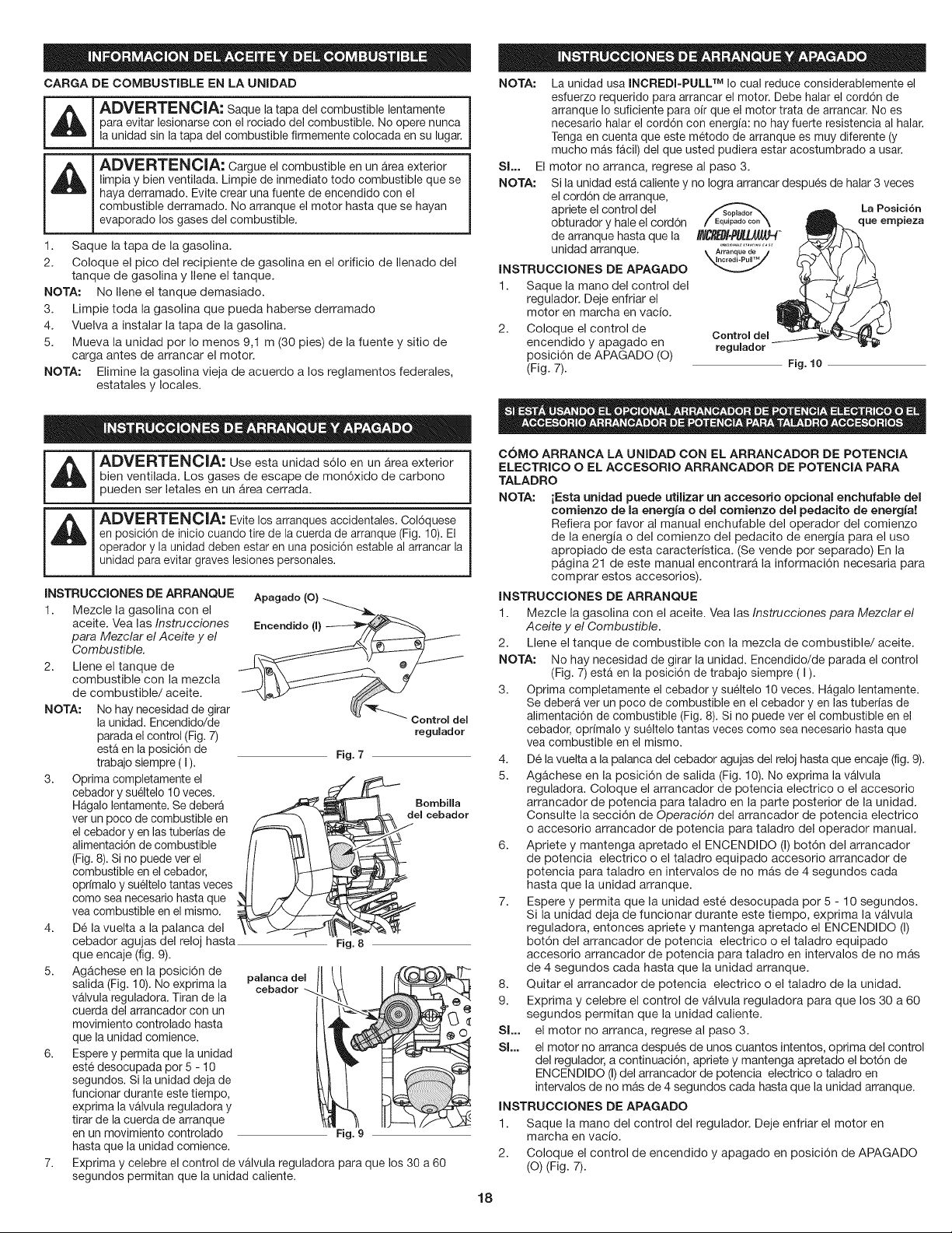
INSTALACION Y AJUSTE DE LA MANIJA EN D
1. Empuje la manija D hacia Mango del eje Bastidor del eje
abajo sobre el bastidor del eje _ A_" J
(Fig. 3). El agujero del perno L"-._"_ J _ .,_Manija en D
hexagonal en la manija debe "-_%.'_'_ _./'J/._
quedar en el lado izquierdo, f/ III
2. Inserte el perno de la manija _ -_'_"'{, _. //'//.J _"X Ajaste
en el agujero hexagonal en la ..... _\ £:::;>'.Z'_(,=,__
manija y empQjela. Coloque r1_.2_dme _"_J_'_'2"-_
laarandelaen elperno _6';uT4ada's_ _J_\X Tuercade
luego enrosque la tuerca de _v_,u,_.... jc_,- v _'_X mariposa
mariposa en el perno. No la Pemo -_
Arandela
apriete hasta que haya
ajustado la manija. Fig. 3
3. Gire la manija en D para colocar el mango sobre la parte superior del
bastidor del eje. Col6quela a una distancia minima de 6 pulgadas
(15.24 cm) del extremo del mango del eje.
4. Mientras sostiene la unidad en la posici6n de funcionamiento (Fig. 11),
coloque la manija en Den el lugar que le brinde el mejor agarre.
5. Apriete la tuerca de mariposa hasta que la manija en D quede firme.
OPERACION DEL SISTEMA DEL ACOPLADOR CONVERTIBLE TM
_L_J DVERTENCIA: Antes de comenzar a usar este accesorio,
lea y comprenda el manual que viene con el accesorio. Siga toda
la informaci6n de seguridad contenida en el mismo.
El sistema del acoplador Convertible TM le permite el uso de estos accesorios
optativos.
• Recortador de bordes de c6sped
• Cultivador
Turbo soplador
• Cortamalezas
Sierra de poste
• Recortador de setos
INSTALACION BEL ACCESORIO BE CORTE U OTROS ACCESORIOS
m
ADVERTENCIA: Para evitar graves lesiones personales,
apague la unidad antes de sacar o instalar accesorios.
PRECAUClON: Antes de operar esta unidad, cerci6rese i
de que el bot6n de liberaci6n est6 completamente encajado en el
J
orificio principal y de que la perilla de ajuste est6 firmemente apretada.
NOTA: Para facilitar la
instalaci6n o remoci6n
de los accesorios,
coloque la unidad sobre
el suelo o sobre un
banco de trabajo.
1. Gire la perilla en sentido
antihorario para aflojarla (Fig. 5).
2. Ala vez que sostiene
firmemente el accesorio,
empQjelo derecho hacia el
interior del acoplador
Convertible TM hasta que el
bot6n de desconexi6n
encaje s61idamente en el
orificio principal (Fig. 4).
NOTA: La alineaci6n del bot6n
de desconexi6n con el
hueco de guia facilitar&
la instalaci6n (Fig. 6).
3. Gire la perilla en sentido
horario para ajustarla (Fig. 5).
Para realizar recortes decorativos
con el accesorio de corte de
cabezal de linea u otro accesorio,
Hoyo primario
Bastidor del
eje superior Bastidor del
eje inferior
Fig. 4
Orificio lateral 90 °
Perilla
Fig. 5
trabe el bot6n de desconexi6n del accesorio de corte u otro accesorio en el
interior del agujero de 90 ° (Fig. 5).
COMO SACAR EL ACCESORIO DE CORTE U OTRO ACCESORIO
1. Gire la perilla en sentido
antihorario para aflojarla (Fig. 5). Acoplador de Bot6n de desconexi6n
Convertible TM
2. Opima y sostenga el bot6n \
de desconexi6n (Fig. 6). I _ _,_
3. A la vez que sujeta la caja del
eje superior, tire del accesorio __
recto hacia afuera del
acoplador Convertible TM (Fig.
4).
Hueco de guia
Fig. 6
INSTRUCCIONES PARA MEZCLAR EL ACEITE Y EL COMBUSTIBLE
El combustible viejo o mal mezclado son los motivos principales del mal
funcionamiento de la unidad. AsegQrese de usar combustible nuevo, limpio
y sin plomo. Siga las instrucciones en detalle para mezclar correctamente el
aceite y el combustible.
Befinicibn de los combustibles de mezcla
I A I ADVERTENCIA: Se ha demostrado que el combustible que i
,_ _ contiene mas de115% de etanol probablemente ocasionara, dados al
!
I motor y anulara, la garantia.
Los combustibles actuales con frecuencia son una mezcla de gasolina y
oxigenantes como por ejemplo etanol, metanol o MTBE (eter). El combustible
mezclado con alcohol absorbe agua. Una cantidad tan pequeda come el 1% de
agua en el combustible puede causar la separaci6n del combustible y el aceite.
Forma acidos cuando esta almacenado. Cuando use combustible mezclado con
alcohol, use combustible nuevo (de menos de 60 dias).
Uso de combustibles de mezcla
Si usted opta por usar un combustible de mezcla o si su uso es inevitable,
tome las precauciones recomendadas.
• Use siempre una mezcla fresca de combustible segQn Io indica su
manual del operador.
Agite siempre la mezcla de combustible antes de cargarlo en la unidad.
Drene el tanque y haga funcionar el motor en seco antes de guardar la unidad.
Uso de aditivos en el combustible
PRECAUCION: Para que el motor funcione correctamente y
con la mayor fiabilidad, preste mucha atenci6n alas instrucciones de
mezcla de aceite y combustible del envase de aceite de 2 ciclos. El
uso de combustible mezclado en forma incorrecta puede dadar
seriamente el motor.
La botella de aceite de 2 ciclos que vino con su unidad contiene un aditivo en el
combustible que ayudar_ a inhibir la corrosi6n y a reducir la formaci6n de
dep6sitos de goma. Utilice siempre un buen 2 de aceite de ciclo diseNado para
motores refrigerados por aire, junto con un aditivo para el combustible, como el
STA-BIL ® estabilizador de gas o un equivalente. Agregue 23 mL (0,8 onzas) de
aditivo de combustible por gal6n de combustible de acuerdo con las
instrucciones del envase. NUNCA agregue aditivos directamente en el tanque
de combustible de la unidad.
Mezcle bien la proporci6n correcta de aceite para motor de 2 ciclos y gasolina
sin plomo en una lata de combustible por separado. Use una proporci6n de
40:1 de combustible y aceite. No los mezcle directamente en el tanque de
combustible de la unidad. Consulte las proporciones especificas de mezcla de
gasolina y aceite en la tabla siguiente.
NOTA: 3,8 litros (un gal6n) de
gasolina sin plomo
mezclada con una botella
de 95 mL (3,2 onzas) de
aceite de 2 ciclos es una
proporci6n de 40:1 de
combustible y aceite.
NOTA: Elimine la mezcla vieja de
aceite y combustible de
acuerdo con los
reglamentos federales,
estatales y locales.
GASOLINA SIN
&CEITE DE 2 CICLOS
PLOMO
95 rnL
3,8 LITROS (3,20NZAS
[1 GALON de EE.UU. FLUIDAS)
1 LITRO 25 mL
PROPORClON DE LA MEZCLA = 40:1
17
CARGA DE COMBUSTIBLE EN LA UNIDAD
' ADVERTENCIA: Saque la taps del combustible lentamente
i _ para evitar lesionarse con el rociado del combustible. No opere nunca
i la unidad sin la taps del combustible firmemente colocada en su lugar.
i
i
; _ ADVERTENCIA: Cargue el combustible en un a.reaexterior
i limpia y bien ventilada. Limpie de inmediato todo combustible que se
i
i hays derramado. Evite crest una fuente de encendido con el
i
i combustible derramado. No arranque el motor hasta que se hayan
i
i evaporado los gases del combustible.
i
i
1. Saque la taps de la gasolina.
2. Coloque el pico del recipiente de gasolina en el orificio de Ilenado del
tanque de gasolina y Ilene el tanque.
NOTA: No Ilene el tanque demasiado.
3. Limpie toda la gasolina que pueda haberse derramado
4. Vuelva a instalar la taps de la gasolina.
5. Mueva la unidad por Io menos 9,1 m (30 pies) de la fuente y sitio de
carga antes de arrancar el motor.
NOTA: Elimine la gasolina vieja de acuerdo a los reglamentos federales,
estatales y locales.
NOTA:
Sl... El
NOTA:
La unidad usa INCREDI-PULL TM Io cual reduce considerablemente el
esfuerzo requerido pars arrancar el motor. Debe halar el cord6n de
arranque Io suficiente pars oir que el motor trata de arrancar. No es
necesario halar el cord6n con energfa: no hay fuerte resistencia al halar.
Tenga en cuenta que este metodo de arranque es muy diferente (y
mucho mas facil) del que usted pudiera estar acostumbrado a usar.
motor no arranca, regrese al paso 3.
Si la unidad estA caliente y no Iogra arrancar despu6s de halar 3 veces
el cord6n de arranque,
apriete el control del
obturador y hale el cord6n
de arranque hasta que la
unidad arranque.
INSTRUCCIONES DE APAGADO
1. Saque la mano del control del
regulador. Deje enfriar el
motor en marcha en vacio.
2. Coloque el control de
encendido y apagado en
posici6n de APAGADO (O)
(Fig. 7).
La Posici6n
que empieza
Control del
regulador
Fig. 10
_, DVERTENCIA: Use esta unidad s61o en un Area exterior
bien ventilada. Los gases de escape de mon6xido de carbono
pueden ser letales en un Area cerrada.
unidad pars evitar graves lesiones personales.
Mezcle la gasolina con el
aceite. Vea las Instrucciones
pars Mezclar el Aceite y el
Combustible.
INSTRUCCIONES DE ARRANQUE ::::::i: :_:
2. Llene el tanque de
combustible con la mezcla
de combustible/aceite.
NOTA: No hay necesidad de girar
la unidad. Encendido!de
parada el control (Fig. 7)
esta en la posici6n de
trabajo siempre (I).
3. Optima completamente el
cebador y sueltelo 10 veces.
Hagalo lentamente. Se debera
ver un poco de combustible en
el cebador yen las tuberfas de
alimentaci6n de combustible
(Fig. 8). Si no puede ver el
combustible en el cebador,
oprfmalo y sueltelo tantas veces
come sea necesario hasta que
vea combustible en el mismo.
4. D6 la vuelta a la palanca del
6.
regulador
Fig. 7
Bombilla
dem cebador
cebador agujas del reloj hasta Fig. 8
que encaje (fig. 9).
Ag_chese en la posici6n de paJanca deJ
salida (Fig. 10). No exprima la oebador
valvula reguladora. Titan de la
cuerda del arrancador con un
movimiento controlado hasta
que la unidad comience.
Espere y permits que la unidad
este desocupada pot 5 - 10
segundos. Si la unidad deja de
funcionar durante este tiempo,
exprima la va.lvula reguladora y
tirar de la cuerda de arranque
en un movimiento controlado Fig. 9
hasta que la unidad comience.
Exprima y celebre el control de vAIvula reguladora pars que los 30 a 60
segundos permitan que la unidad caliente.
COMO ARRANCA LA UNIDAD CON EL ARRANCADOR DE POTENCIA
ELECTRJCO O EL ACCESORIO ARRANCADOR DE POTENCIA PARA
TALADRO
NOTA: iEsta unidad puede utilizar un accesorio opcionaJ enchufabJe del
comienzo de la energJa o del cornienzo del pedacJto de energJa!
Refiera por favor al manual enchufable del operador del comienzo
de la energia o del comienzo del pedacito de energia pars el uso
apropiado de esta caracteristica. (Se vende por separado) En la
pagina 21 de este manual encontrarA la informaci6n necesaria pars
comprar estos accesorios).
INSTRUCCIONES DE ARRANQUE
1. Mezcle la gasolina con el aceite. Vea las Instrucciones pars Mezclar el
Aceite y el Combustible.
2. Llene el tanque de combustible con la mezcla de combustible/aceite.
NOTA: No hay necesidad de girar la unidad. Encendido/de parada el control
(Fig. 7) esta en la posici6n de trabajo siempre ( I ).
3. Optima completamente el cebador y sueltelo 10 veces. Hagalo lentamente.
Se debera ver un poco de combustible en el cebador yen las tuberias de
alimentaci6n de combustible (Fig. 8). Si no puede ver el combustible en el
cebador, oprfmalo y su61telo tantas veces come sea necesario hasta que
vea combustible en el mismo.
4. De la vuelta a la palanca del cebador agujas del reloj hasta que encaje (fig. 9).
5. Agachese en la posici6n de salida (Fig. 10). No exprima la vAIvula
reguladora. Coloque el arrancador de potencia electrico o el accesorio
arrancador de potencia pars taladro en la parte posterior de la unidad.
Consulte la secci6n de Operacidn del arrancador de potencia electrico
o accesorio arrancador de potencia pars taladro del operador manual.
6. Apriete y mantenga apretado el ENCENDIDO (I) bot6n del arrancador
de potencia electrico o el taladro equipado accesorio arrancador de
potencia pars taladro en intervalos de no mAs de 4 segundos cads
hasta que la unidad arranque.
7. Espere y permits que la unidad est6 desocupada por 5 - 10 segundos.
Si la unidad deja de funcionar durante este tiempo, exprima la valvula
reguladora, entonces apriete y mantenga apretado el ENCENDIDO (I)
bot6n del arrancador de potencia electrico o el taladro equipado
accesorio arrancador de potencia pars taladro en intervalos de no mas
de 4 segundos cads hasta que la unidad arranque.
8. Quitar el arrancador de potencia electrico o el taladro de la unidad.
9. Exprima y celebre el control de vAIvula reguladora pars que los 30 a 60
segundos permitan que la unidad caliente.
Sl... el motor no arranca, regrese al paso 3.
Sl... el motor no arranca despues de unos cuantos intentos, optima del control
del regulador, a continuaci6n, apriete y mantenga apretado el bot6n de
ENCENDIDO (I)del arrancador de potencia electrico o taladro en
intervalos de no mas de 4 segundos cads hasta que la unidad arranque.
INSTRUCCIONES DE APAGADO
1. Saque la mano del control del regulador. Deje enfriar el motor en
marcha en vacio.
2. Coloque el control de encendido y apagado en posici6n de APAGADO
(O) (Fig. 7).
18
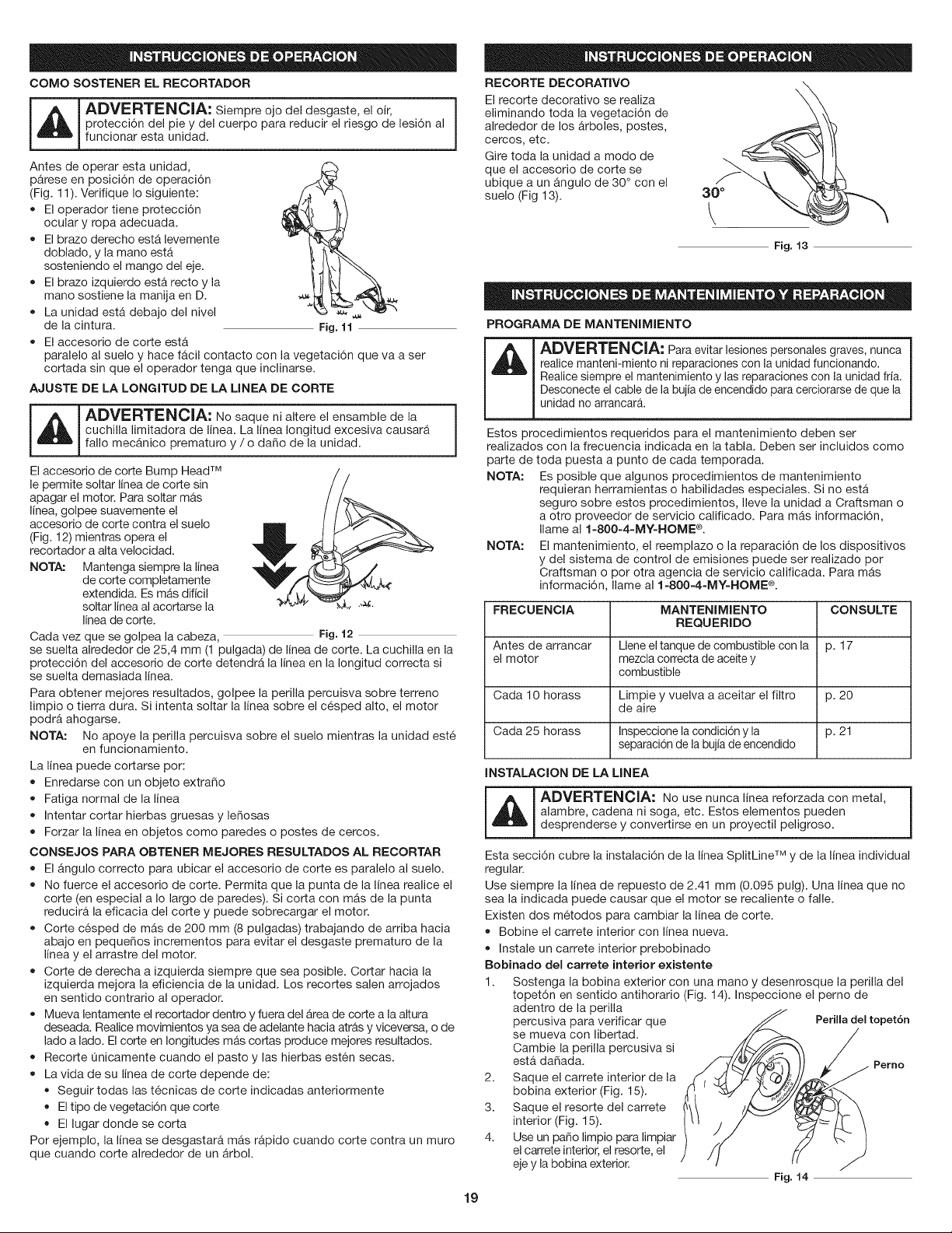
COMO SOSTENER EL RECORTADOR
_ DVERTENClA: Siempre ojo del desgaste, el oir,
protecci6n del pie y del cuerpo para reducir el riesgo de lesi6n al
funcionar esta unidad.
Antes de operar esta unidad,
parese en posici6n de operaci6n
(Fig. 11). Verifique Io siguiente:
• El operador tiene protecci6n
ocular y ropa adecuada.
• El brazo derecho esta levemente
doblado, y la mano esta
sosteniendo el mango del eje.
El brazo izquierdo esta recto y la
mano sostiene la manija en D.
• La unidad esta debajo del nivel ,_
de la cintura. Fig. 11
• El accesorio de corte esta
paralelo al suelo y hace fAcil contacto con la vegetaci6n que va a ser
cortada sin que el operador tenga que inclinarse.
AJUSTE DE LA LONGITUD DE LA LHNEA DE CORTE
_ DVERTENCIA: No saque ni altere el ensamble de la
cuchilla limitadora de linea. La linea Iongitud excesiva causarA
fallo mecAnico prematuro y / o daSo de la unidad.
El accesorio de corte Bump Head TM
le permite soltar linea de corte sin
apagar el motor. Para soltar mas
linea, golpee suavemente el
accesorio de corte contra el suelo
(Fig. 12) mientras opera el
recortador a alta velocidad.
NOTA: Mantenga siempre la linea
de corte completamente
extendida. Es mAs diflcil
soltar linea al acortarse la .'_-
linea de corte.
Cada vez que se golpea la cabeza, Fig. 12
se suelta alrededor de 25,4 mm (1 pulgada) de linea de corte. La cuchilla en la
protecci6n del accesorio de corte detendrA la linea en la Iongitud correcta si
se suelta demasiada linea.
Para obtener mejores resultados, golpee la perilla percuisva sobre terreno
limpio o tierra dura. Si intenta soltar la linea sobre el c6sped alto, el motor
podrA ahogarse.
NOTA: No apoye la perilla percuisva sobre el suelo mientras la unidad est6
en funcionamiento.
La linea puede cortarse por:
Enredarse con un objeto extraSo
Fatiga normal de la linea
Intentar cortar hierbas gruesas y le_osas
• Forzar la linea en objetos como paredes o postes de cercos.
CONSEJOS PARA OBTENER MEJORES RESULTADOS AL RECORTAR
• El Angulo correcto para ubicar el accesorio de corte es paralelo al suelo.
• No fuerce el accesorio de corte. Permita que la punta de la linea realice el
corte (en especial a Io largo de paredes). Si corta con mAs de la punta
reducira la eficacia del corte y puede sobrecargar el motor.
Corte cesped de mas de 200 mm (8 pulgadas) trabajando de arriba hacia
abajo en peque_os incrementos para evitar el desgaste prematuro de la
linea y el arrastre del motor.
Corte de derecha a izquierda siempre que sea posible. Cortar hacia la
izquierda mejora la eficiencia de la unidad. Los recortes salen arrojados
en sentido contrario al operador.
Mueva lentamente el recortador dentro y fuera del Area de corte a la altura
deseada. Realice movimientos ya sea de adelante hacia atras y viceversa, o de
lado a lado. El corte en longitudes mas cortas produce mejores resultados.
Recorte Onicamente cuando el pasto y las hierbas est6n secas.
La vida de su linea de corte depende de:
Seguir todas las t6cnicas de corte indicadas anteriormente
El tipo de vegetaci6n que corte
El lugar donde se corta
Por ejemplo, la linea se desgastara mAs rApido cuando corte contra un muro
que cuando corte alrededor de un Arbol.
RECORTE DECORATIVO
El recorte decorativo se realiza
eliminando toda la vegetaci6n de
alrededor de los Arboles, postes,
cercos, etc.
Gire toda la unidad a modo de
que el accesorio de corte se
ubique a un angulo de 30 ° con el
suelo (Fig 13).
30°
Fig. 13
19
PROGRAMA DE MANTENIMIENTO
L_iJ DVERTENOIA: Para evitar lesiones personales graves, nunca
realice manteni-miento ni reparaciones con la unidad funcionando.
Realice siempre el mantenimiento y las reparaciones con la unidad fria.
Desconecte el cable de la bujia de encendido para cerciorarse de que la
unidad no arrancar&
Estos procedimientos requeridos para el mantenimiento deben ser
realizados con la frecuencia indicada en la tabla. Deben ser incluidos como
parte de toda puesta a punto de cada temporada.
NOTA: Es posible que algunos procedimientos de mantenimiento
requieran herramientas o habilidades especiales. Si no esta
seguro sobre estos procedimientos, Ileve la unidad a Craftsman o
a otro proveedor de servicio calificado. Para mAs informaci6n,
Ilame al 1=800=4=MY=HOME _.
NOTA: El mantenimiento, el reemplazo o la reparaci6n de los dispositivos
y del sistema de control de emisiones puede ser realizado por
Craftsman o por otra agencia de servicio calificada. Para mAs
informaci6n. Ilame al 1=800=4=MY=HOME _e.
FRECUENCIA MANTENIMIENTO CONSULTE
REQUERHDO
Antes de arrancar Llene el tanque de combustible con la p. 17
el motor mezcla correcta de aceite y
combustible
Cada 10 horass Limpie y vuelva a aceitar el filtro p. 20
de aire
Cada 25 horass Inspeccione lacondici6n y la p. 21
separaci6n de la bujia de encendido
INSTALAOION DE LA MNEA
ADVERTENClA: No use nunca linea reforzada con metal, i
I alambre, cadena ni soga, etc. Estos elementos pueden
J
desprenderse y convert rse en un proyect pe groso.
Esta secci6n cubre la instalaci6n de la linea SplitLine TM y de la linea individual
regular.
Use siempre la linea de repuesto de 2.41 mm (0.095 pulg). Una linea que no
sea la indicada puede causar que el motor se recaliente o falle.
Existen dos m6todos para cambiar la linea de corte.
• Bobine el carrete interior con linea nueva.
• Instale un carrete interior prebobinado
Bobinado del carrete interior existente
1. Sostenga la bobina exterior con una mano y desenrosque la perilla del
topet6n en sentido antihorario (Fig. 14). Inspeccione el perno de
adentro de la perilla
percusiva para verificar que Perilla del topetSn
se mueva con libertad.
Cambie la perilla percusiva si
esta da_ada. Perno
2. Saque el carrete interior de la
bobina exterior (Fig. 15).
3. Saque el resorte del carrete
interior (Fig. 15).
4. Use un paso limpio para limpiar
el carrete interior, el resorte, el
eje y la bobina exterior.
Fig. 14
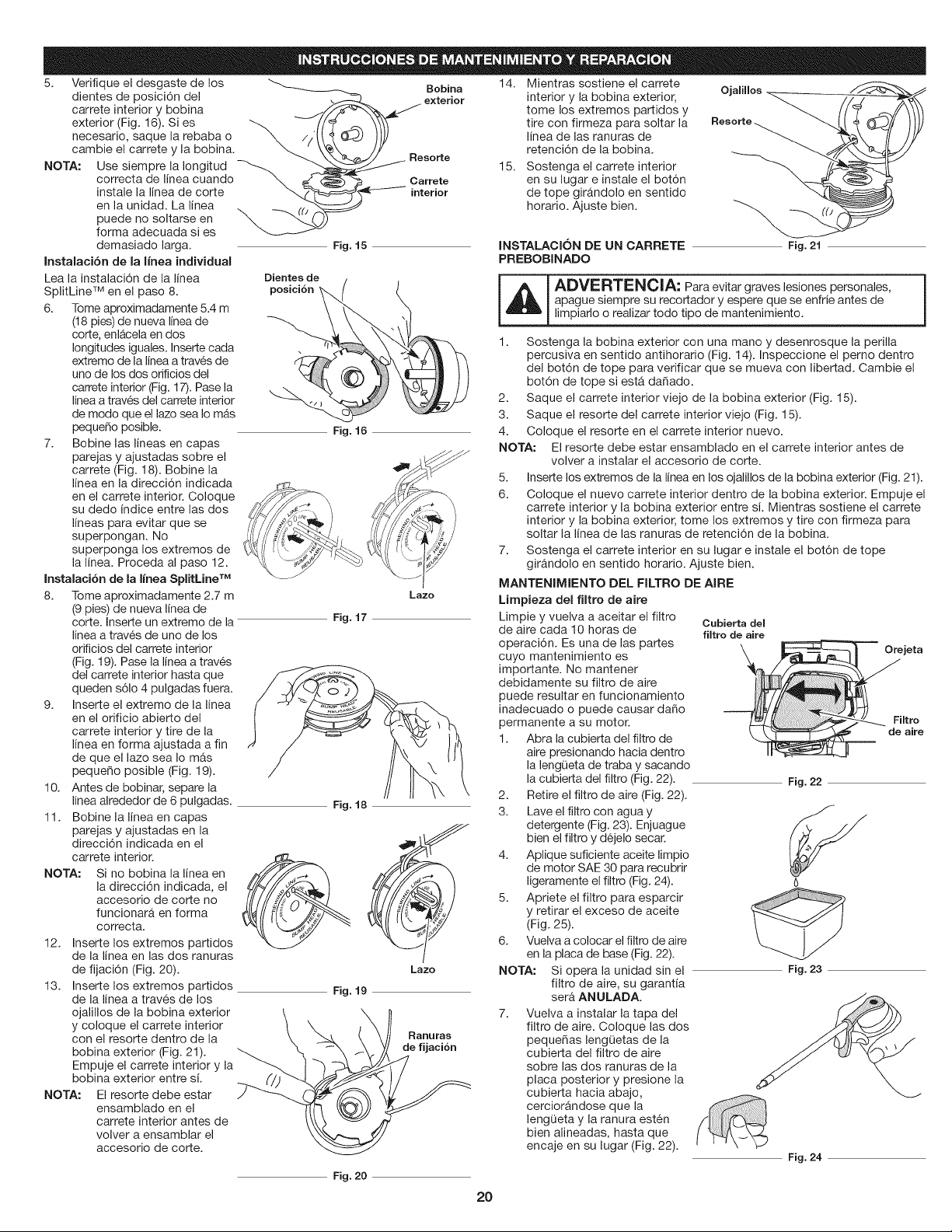
5,
Verifique el desgaste de los
dientes de posici6n del
carrete interior y bobina
exterior (Fig. 16). Si es
necesario, saque la rebaba o
cambie el carrete y la bobina.
Use siempre la Iongitud
correcta de linea cuando
instale la linea de corte
NOTA:
__)___Re Bobina 14. Mientras sostiene el carrete Ojalillos
exterior interior y la bobina exterior, "_-_.
tome los extremes partidos y
tire con firmeza para soltar la Resorte.
) linea de las ranuras de _._/_\_
retenci6n de la bobina.
serte 15. Sostenga el carrete interior
Carrete en su lugar e instale el bot6n
_-%_==_------- interior de tope gir&ndolo en sentido
horatio. Ajuste bien. "_-_
Fig. 15 Fig. 21
Fig. 16
Lazo
Fig. 17
en la unidad. La linea
puede no soltarse en
forma adecuada si es
demasiado larga.
Instalaci6n de la linea individual
Lea la instalaci6n de la linea
SplitLine TM en el paso 8.
6. Tome aproximadamente 5.4 m
(18 pies) de nueva linea de
corte, enl&cela en dos
longitudes iguales. Inserte cada
extreme de la linea a trav6s de
uno de los dos orificios del
carrete interior (Fig. 17). Pase la
linea a traves del carrete interior
de mode que el lazo sea Io mas
pequeSo posible.
7. Bobine las lineas en capas
parejas y ajustadas sobre el
carrete (Fig. 18). Bobine la
lineaen la direcci6n indicada
en el carrete interior. Coloque
su dedo indice entre las dos
lineas para evitar que se
superpongan. No
superponga los extremes de
la linea. Proceda al paso 12.
Instalaci6n de la Iinea SpiitMne TM
8. Tome aproximadamente 2.7 m
(9 pies) de nueva linea de
corte. Inserte un extreme de la
linea a trav6s de uno de los
orificios del carrete interior
(Fig. 19). Pase la linea a trav6s
del carrete interior hasta que
queden s61o4 pulgadas fuera.
9. Inserte el extreme de la linea
en el orificio abierto del
carrete interior y tire de la
lineaen forma ajustada a fin
de que el lazo sea Io m&s
pequeSo posible (Fig. 19).
10. Antes de bobinar, separe la
linea alrededor de 6 pulgadas.
11. Bobine la lineaen capas
parejas y ajustadas en la
direcci6n indicada en el
carrete interior.
NOTA: Si no bobina la linea en
la direcci6n indicada, el
accesorio de corte no
funcionara en forma
correcta.
12. Inserte los extremes partidos
de la lineaen las dos ranuras
de fijaci6n (Fig. 20).
13. Inserte los extremes partidos
de la linea a trav6s de los
ojalillos de la bobina exterior
y coloque el carrete interior
con el resorte dentro de la
bobina exterior (Fig. 21).
Empuje el carrete interior y la
bobina exterior entre si.
NOTA: El resorte debe estar
ensamblado en el
carrete interior antes de
volver a ensamblar el
accesorio de corte.
Fig. 18
Lazo
Ranuras
de fijaci6n
Fig. 19
INSTALACION DE UN CARRETE
PREBOBINADO
_L__J DVERTENCIA: Para evitar graves lesiones personales,
apague siempre su recortador y espere que se enfrie antes de
limpiarlo o realizar todo tipo de mantenimiento.
1. Sostenga la bobina exterior con una mane y desenrosque la perilla
percusiva en sentido antihorario (Fig. 14). Inspeccione el perno dentro
del bot6n de tope para verificar que se mueva con libertad. Cambie el
bot6n de tope si est& da_ado.
2. Saque el carrete interior viejo de la bobina exterior (Fig. 15).
3. Saque el resorte del carrete interior viejo (Fig. 15).
4. Coloque el resorte en el carrete interior nuevo.
NOTA: El resorte debe estar ensamblado en el carrete interior antes de
volver a instalar el accesorio de corte.
5. Inserte los extremes de la lineaen los ojalillos de la bobina exterior (Fig. 21).
6. Coloque el nuevo carrete interior dentro de la bobina exterior. Empuje el
carrete interior y la bobina exterior entre si. Mientras sostiene el carrete
interior y la bobina exterior, tome los extremes y tire con firmeza para
soltar la linea de las ranuras de retenci6n de la bobina.
7. Sostenga el carrete interior en su lugar e instale el bot6n de tope
girAndolo en sentido horario. Ajuste bien.
MANTENIMIENTO DEL FILTRO DE AIRE
Lirnpieza del fiitro de mire
Limpie y vuelva a aceitar el filtro
de mire cada 10 horas de
operaci6n. Es una de las partes
cuyo mantenimiento es
importante. No mantener
debidamente su filtro de mire
puede resultar en funcionamiento
inadecuado o puede causar da_o
permanente a su motor.
1. Abra la cubierta del filtro de
mire presionando hacia dentro
la lengQeta de traba y sacando
la cubierta del filtro (Fig. 22).
2. Retire el filtro de mire (Fig. 22).
3. Lave el filtro con agua y
detergente (Fig. 23). Enjuague
bien el filtro y dejelo secar.
4. Aplique suficiente aceite limpio
de motor SAE 30 para recubrir
ligeramente el filtro (Fig. 24).
5. Apriete el filtro para esparcir
y retirar el exceso de aceite
(Fig. 25).
6. Vuelva a colocar el filtro de mire
en la placa de base (Fig. 22).
NOTA: Si opera la unidad sin el
filtro de mire, su garantia
sera ANULADA.
7. Vuelva a instalar la tapa del
filtro de mire. Coloque las dos
pequeSas lengQetas de la
cubierta del filtro de mire
sobre las dos ranuras de la
placa posterior y presione la
cubierta hacia abajo,
cercior&ndose que la
lengQeta y la ranura est6n
bien alineadas, hasta que
encaje en su lugar (Fig. 22).
Cubierta del
fiitro de mire
Orejeta
_F_'_"ilt r°
de mire
Fig. 22
Fig. 23
Fig. 24
Fig. 20
20
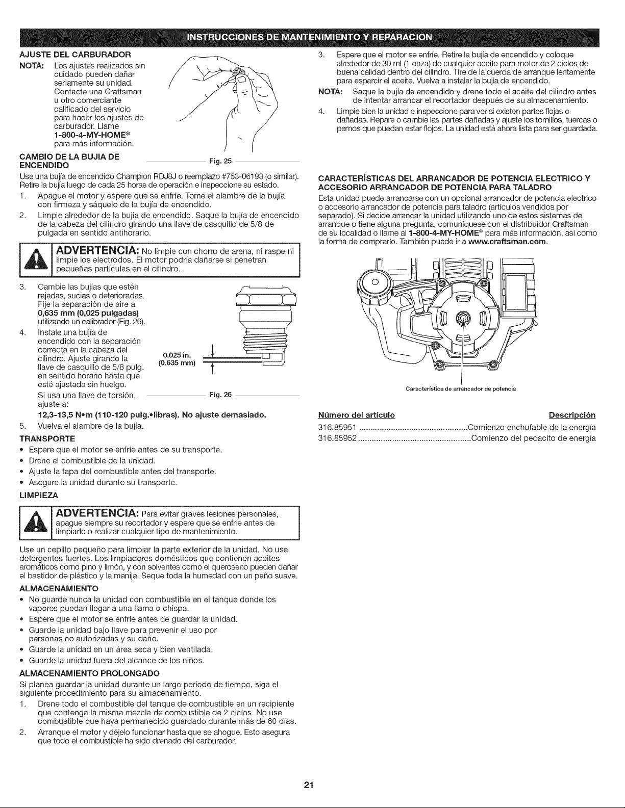
AJUSTE DEL CARBURADOR
NOTA: Los ajustes realizados sin
cuidado pueden daSar
seriamente su unidad.
Contacte una Craftsman
u otro comerciante
calificado del servicio
para hacer los ajustes de
carburador. Llame
1=800=4-MY=HOME ®
para mas informaci6n.
CAMBIO DE LA BUJIA DE
ENCENDIDO Fig. 25
Use una bujia de encendido Champion RDJSJ o reemplazo #753-06193 (o similar).
Retire la bujia luego de cada 25 horas de operaci6n e inspeccione su estado.
1. Apague el motor y espere que se enfrie. Tome el alambre de la bujia
con firmeza y s&quelo de la bujia de encendido.
2. Limpie alrededor de la bujia de encendido. Saque la bujia de encendido
de la cabeza del cilindro girando una Ilave de casquillo de 5/8 de
pulgada en sentido antihorario.
_ ADVERTENClA: No limpie con chorro de arena, ni raspe ni |
I
limpie los electrodos. El motor podria da_arse si penetran
1
peque_as particulas en el cilindro.
3. Cambie las bujias que est6n
rajadas, sucias o deterioradas.
Fije la separaci6n de aire a
0,635 rnrn (0,025 pulgadas}
utilizando un calibrador (Fig. 26).
4. Instale una bujia de
encendido con la separaci6n
correcta en la cabeza del _[
0.025 in.
cilindro. Ajuste girando la (0.635 ram)
T
Ilave de casquillo de 5/8 pulg. _-
en sentido horario hasta que
est6 ajustada sin huelgo.
Si usa una Ilave de torsi6n, Fig. 26
ajuste a:
12,3-13,5 Nora (110-120 pulg.olibras}. No ajuste demasiado.
5. Vuelva el alambre de la bujia.
TRANSPORTE
• Espere que el motor se enfrie antes de su transporte.
• Drene el combustible de la unidad.
Ajuste la tapa del combustible antes del transporte.
Asegure la unidad durante su transporte.
LIMPIEZA
_ DVERTENCIA: Para evitar graves lesiones personales,
apague siempre su recortador y espere que se enfrie antes de
limpiarlo o realizar cualquier tipo de mantenimiento.
3. Espere que el motor se enfrie. Retire la bujia de encendido y coloque
alrededor de 30 ml (1 onza) de cualquier aceite para motor de 2 ciclos de
buena calidad dentro del cilindro. Tire de la cuerda de arranque lentamente
para esparcir el aceite. Vuelva a instalar la bujia de encendido.
NOTA: Saque la bujia de encendido y drene todo el aceite del cilindro antes
de intentar arrancar el recortador despues de su almacenamiento.
4. Limpie bien la unidad e inspeccione para ver si existen partes fiojas o
da_adas. Repare o cambie las partes da_adas y ajuste los tomillos, tuercas o
pernos que puedan estar flojos. La unidad estA ahora lista para ser guardada.
CARACTERJSTICAS DEL ARRANCADOR DE POTENCIA ELECTRICO Y
ACCESORIO ARRANCADOR DE POTENCIA PARA TALADRO
Esta unidad puede arrancarse con un opcional arrancador de potencia electrico
o accesorio arrancador de potencia para taladro (articulos vendidos por
separado). Si decide arrancar la unidad utilizando uno de estos sistemas de
arranque o tiene alguna pregunta, comuniquese con el distribuidor Craftsman
de su Iocalidad o Ilame al 1-800-4=MY-HOME _ para m&s informaci6n, asi como
la forma de comprarlo. Tambien puede ira www.craftsman.com.
O. I_:::_ c:::_ I _
Caracteristica de arrancador de potencia
Nemero del artfculo Descripci6n
316.85951 ................................................ Comienzo enchufable de la energia
316.85952 .................................................. Comienzo del pedacito de energia
Use un cepillo peque_o para limpiar la parte exterior de la unidad. No use
detergentes fuertes. Los limpiadores dom6sticos que contienen aceites
arom&ticos como pino y lim6n, y con solventes como el queroseno pueden da_ar
el bastidor de plastico y la manija. Seque toda la humedad con un paso suave.
ALMAOENAMIENTO
No guarde nunca la unidad con combustible en el tanque donde los
vapores puedan Ilegar a una llama o chispa.
Espere que el motor se enfrie antes de guardar la unidad.
Guarde la unidad bajo Ilave para prevenir el uso por
personas no autorizadas y su da_o.
Guarde la unidad en un area seca y bien ventilada.
• Guarde la unidad fuera del alcance de los ni_os.
ALMACENAMIENTO PROLONGADO
Si planea guardar la unidad durante un largo periodo de tiempo, siga el
siguiente procedimiento para su almacenamiento.
1. Drene todo el combustible del tanque de combustible en un recipiente
que contenga la misma mezcla de combustible de 2 ciclos. No use
combustible que haya permanecido guardado durante mAs de 60 dias.
2. Arranque el motor y d6jelo funcionar hasta que se ahogue. Esto asegura
que todo el combustible ha sido drenado del carburador.
21
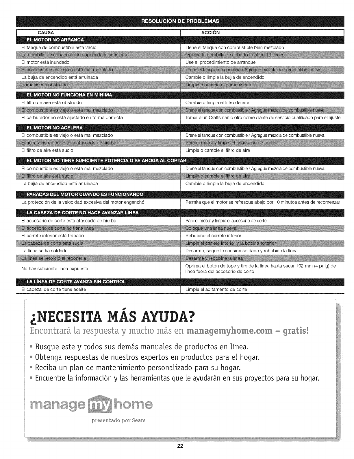
CAUSA ACCION
El tanque de combustible estA vacio
El motor esta inundado
La bujia de encendido esta arruinada
El filtro de aire esta obstruido
El carburador no estA ajustado en forma correcta
El combustible es viejo o esta mal mezclado
El filtro de aire estA sucio
El combustible es viejo o est& mal mezclado
La bujia de encendido estA arruinada
La protecci6n de la velocidad excesiva del motor enganch6
El accesorio de corte esta atascado de hierba
El carrete interior estA trabado
La linea se ha soldado
No hay suficiente linea expuesta
El cabezal de corte tiene aceite
Llene el tanque con combustible bien mezclado
Use el procedimiento de arranque
Cambie o limpie la bujia de encendido
Cambie o limpie el filtro de aire
Tomar a un Craftsman o otro comerciante de servicio cualificado para el ajuste
Drene el tanque con combustible / Agregue mezcla de combustible nueva
Limpie o cambie el filtro de aire
Drene el tanque con combustible / Agregue mezcla de combustible nueva
Cambie o limpie la bujia de encendido
Permita que el motor se refresque abajo pot 10 minutos antes de recomenzar
Pare el motor y limpie el accesorio de corte
Rebobine el carrete interior
Desarme, saque la secci6n soldada y rebobine la linea
Optima el bot6n de tope y tire de la linea hasta sacar 102 mm (4 pulg) de
linea fuera del accesorio de corte
Limpie el aditamento de corte
SITA MAS AYUDA?
Encontrar_ _a respuesta y mucho m_s en managemyhomeocOm - gratis!
o Busque este y todos sus demos manua[es de productos en [fnea.
o Obtenga respuestas de nuestros expertos en productos para e[ hogar.
o Redba un p[an de mantenimiento persona[izado para su hogar.
o Encuentre [a informad6n y [as herramientas que [e ayudar_n en sus proyectos para su hogar.
22
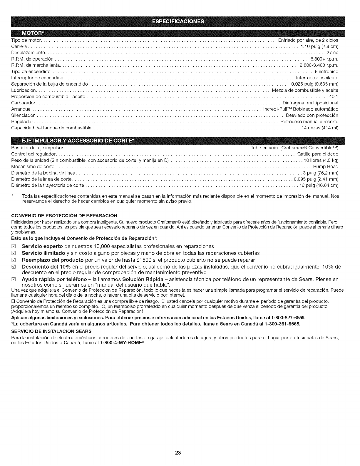
Tipo de motor .......................................................................................... Enfriado por aire, de 2 ciclos
Carrera ........................................................................................................ 1.10 pulg (2.8 cm)
Desplazamiento ........................................................................................................... 27 cc
R.RM. de operaci6n ................................................................................................. 6,800+ r.p.m.
R.RM. de marcha lenta ........................................................................................... 2,800-3,400 r.p.m.
Tipo de encendido .................................................................................................... Electr6nico
Interruptor de encendido ........................................................................................ Interruptor oscilante
Separaci6n de la bujia de encendido ............................................................................. 0.025 pulg (0.635 mm)
Lubricaci6n .......................................................................................... Mezcla de combustible y aceite
Proporci6n de combustible - aceite ............................................................................................ 40:1
Carburador .............................................................................................. Diafragma, multiposicional
Arranque ........................................................................................ Incredi-Pull TM Bobinado automatico
Silenciador ............................................................................................... Desviado con protecci6n
Regulador .............................................................................................. Retroceso manual a resorte
Capacidad del tanque de combustible ................................................................................ 14 onzas (414 ml)
Bastidor del eje impulsor ...................................................................... Tube en acier (Craftsman® Convertible TM)
Control del regulador ............................................................................................ Gatillo para el dedo
Peso de la unidad (Sin combustible, con accesorio de corte, y manija en D) ................................................... 10 libras (4.5 kg)
Mecanismo de corte .................................................................................................. Bump Head
DiAmetro de la bobina de linea ....................................................................................... 3 pulg (76,2 mm)
Diametro de la linea de corte ..................................................................................... 0.095 pulg (2.41 mm)
DiAmetro de la trayectoria de corte .................................................................................. 16 pulg (40.64 cm)
* Toda las especificaciones contenidas en este manual se basan en la informaci6n mAs reciente disponible en el momento de impresi6n del manual. Nos
reservamos el derecho de hacer cambios en cualquier momento sin aviso previo.
CONVENIO DE PROTECClON DE REPARAClON
Felicidades pot haber realizado una compra inteligente. Su nuevo producto Craftsman® esta. disefiado y fabricado para ofrecefle afios de funcionamiento confiable. Pero
como todos los productos, es posible que sea necesario repararlo de vez en cuando. Ahi es cuando tener un Convenio de Protecci6n de Reparaci6n puede ahorrarle dinero
y problemas.
Esto es Io que incluye el Convenio de Protecci6n de Reparaci6n*:
[] Servicio experto de nuestros 10,000 especialistas profesionales en reparaciones
[] Servicio ilimitado y sin costo alguno por piezas y mano de obra en todas las reparaciones cubiertas
[] Reemplazo del producto por un valor de hasta $1500 si el producto cubierto no se puede reparar
[] Descuento del 10% en el precio regular del servicio, asi como de las piezas instaladas, que el convenio no cubra; igualmente, 10% de
descuento en el precio regular de comprobaci6n de mantenimiento preventivo
[] Ayuda r_pida pot tel_fono - la Ilamamos Soluci6n R_pida - asistencia tecnica por telefono de un representante de Sears. Piense en
nosotros como si fueramos un "manual del usuario que habla".
Una vez que adquiera el Convenio de Protecci6n de Reparaci6n, todo Io que necesita es hacer una simple Ilamada para programar el servicio de reparaci6n. Puede
Ilamar a cualquier hora del dia o de la noche, o hacer una cita de servicio pot Internet.
El Convenio de Protecci6n de Reparaci6n es una compra libre de riesgo. Si usted cancela por cualquier motivo durante el periodo de garantia del producto,
proporcionaremos un reembolso completo. O, un reembolso prorrateado en cualquier momento despues de que venza el periodo de garantia del producto.
iAdquiera hoy mismo su Convenio de Protecci6n de Reparaci6n!
Aplican algunas lirnitaciones y exclusiones. Pars obtener precios e informaci6n adicional en los Estados Unidos, Ilarne al 1-800-827-6655.
*La cobertura en Canad_ varia en algunos articulos. Para obtener todos los detalles, Ilame a Sears en Canad_ al 1-800-361-6665.
SERVICIO DE INSTALAClON SEARS
Para la instalaci6n de electrodomesticos, abridores de puertas de garaje, calentadores de agua, y otros productos para el hogar pot profesionales de Sears,
en los Estados Unidos o CanadA, Ilame al 1=800=4=MY=HOME ®.
23

24

25

26

27

28

29
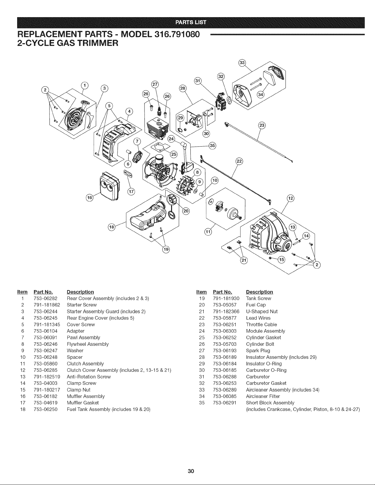
REPLACEMENT PARTS - MODEL 316.791080
2-CYCLE GAS TRIMMER
item Part No. Description item Part No. Description
1 753-06282 Rear Cover Assembly (includes 2 & 3) 19 791-181930 Tank Screw
2 791-181862 Starter Screw 20 753-05057 Fuel Cap
3 753-06244 Starter Assembly Guard (includes 2) 21 791-182366 U-Shaped Nut
4 753-06245 Rear Engine Cover (includes 5) 22 753-05877 Lead Wires
5 791-181345 Cover Screw 23 753-06251 Throttle Cable
6 753-06104 Adapter 24 753-06303 Module Assembly
7 753-06091 Pawl Assembly 25 753-06252 Cylinder Gasket
8 753-06246 Flywheel Assembly 26 753-05703 Cylinder Bolt
9 753-06247 Washer 27 753-06193 Spark Plug
10 753-06248 Spacer 28 753-06189 Insulator Assembly (includes 29)
11 753-05860 Clutch Assembly 29 753-06184 Insulator O-Ring
12 753-06285 Clutch Cover Assembly (includes 2, 13-15 & 21) 30 753-06185 Carburetor O-Ring
13 791-182519 Anti-Rotation Screw 31 753-06288 Carburetor
14 753-04003 Clamp Screw 32 753-06253 Carburetor Gasket
15 791-180217 Clamp Nut 33 753-06289 Aircleaner Assembly (includes 34)
16 753-06182 Muffler Assembly 34 753-06085 Aircleaner Filter
17 753-04619 Muffler Gasket 35 753-06291 Short Block Assembly
18 753-06250 Fuel Tank Assembly (includes 19 & 20) (includes Crankcase, Cylinder, Piston, 8-10 & 24-27)
3O
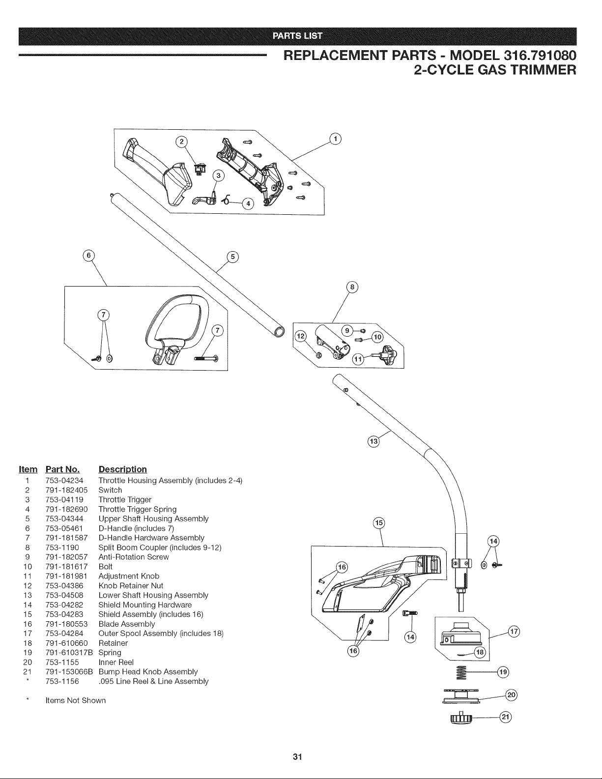
REPLACEMENT PARTS - MODEL 316.791080
2-CYCLE GAS TRIMMER
item Part No.
1 753-04234
2 791-182405
3 753-04119
4 791-182690
5 753-04344
6 753-05461
7 791-181587
8 753-1190
9 791-182057
10 791-181617
11 791-181981
12 753-04386
13 753-04508
14 753-04282
15 753-04283
16 791-180553
17 753-04284
18 791-610660
19 791-610317B
20 753-1155
21 791-153066B
* 753-1156
Description
Throttle Housing Assembly (includes 2-4)
Switch
Throttle Trigger
Throttle Trigger Spring
Upper Shaft Housing Assembly
D-Handle (includes 7)
D-Handle Hardware Assembly
Split Boom Coupler (includes 9-12)
Anti-Rotation Screw
Bolt
Adjustment Knob
Knob Retainer Nut
Lower Shaft Housing Assembly
Shield Mounting Hardware
Shield Assembly (includes 16)
Blade Assembly
Outer Spool Assembly (includes 18)
Retainer
Spring
Inner Reel
Bump Head Knob Assembly
.095 Line Reel & Line Assembly
* Items Not Shown
31

Your Home
For troubleshooting, product manuals and home solutions advice:
www.managemyhome.com
For repair- in your home - of all major brand appliances,
lawn and garden equipment, or heating and cooling systems,
no matter who made it, no matter who sold it!
For the replacement parts, accessories and
owner's manuals that you need to do-it-yourself.
For Sears professional installation of home appliances
and items like garage door openers and water heaters.
1-800=4=MY-HOME ® (1-800-469-4663)
Call anytime, day or night (U.S.A. and Canada)
www, sears,com www, sears,ca
Our Home
For repair of carry-in items like vacuums, lawn equipment,
and electronics, call anytime for the location of your nearest
Sears Parts & Repair Service Center
1-800-488-1222 (U.S.A.)
www.sears.com
1-800-469-4663 (Canada)
www.sears.ca
To purchase a protection agreement on a product serviced by Sears:
1-800-827-6655 (U.S.A.) 1-800-361-6665 (Canada)
Para pedir servicio de reparacidn Au Canada pour service en fran(;ais:
a domicilio, y para ordenar piezas: 1-800=Li=-FOYI=RMC
1-800=SU - HOGAR ® (1-800-533-6937)
(1-888-784-6427) www.sears.ca
www.sears.com
® Registered Trademark / TMTrademark of KCD IP, LLC in the United States, or Sears Brands, LLC in other countries
® Marca Registrada / TMMarca de F&brica de KCD IP, LLC en Estados Unidos, o Sears Brands, LLC in otros paises
MD
MCMarque de commerce / Marque d6pos6e de Sears Brands, LLC