1
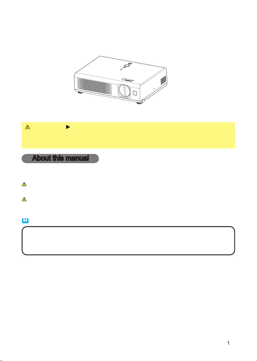
Projector
User's Manual – Operating Guide
CP-RX60
Thank you for purchasing this projector.
WARNING
►
Before using, read the "User's Manual - Safety Guide" and
these manuals to ensure correct usage through understanding. After reading,
store them in a safe place for future reference.
About this manual
Various symbols are used in this manual. The meanings of these symbols are
described below.
WARNING
This symbol indicates information that, if ignored, could possibly
result in personal injury or even death due to incorrect handling.
CAUTION
This symbol indicates information that, if ignored, could result
possibly in personal injury or physical damage due to incorrect
handling.
Please refer to the pages written following this symbol.
NOTE
• The information in this manual is subject to change without notice.
• The manufacturer assumes no responsibility for any errors that may appear in this manual.
• The reproduction, transmission or use of this document or contents is not permitted without
express written authority.
Trademark acknowledgment
• VGA and XGA are registered trademarks of the International Business Machines
Corporation.
• Apple and Mac are registered trademarks of Apple Computer, Inc.
• VESA and SVGA are trademarks of the Video Electronics Standard Association.
• Windows is a registered trademark of Microsoft Corporation.
• Internet Explorer is a trademark of Microsoft Corporation.
All other trademarks are the property of their respective owners.
2
About th
is manua
l
. . . . . . . . . .
1
Content
s
. . . . . . . . . . . . . . . . .
2
Projector feature
s
. . . . . . . . . .
3
About contents of package
. .
3
Part name
s
. . . . . . . . . . . . . . .
4
Projecto
r
. . . . . . . . . . . . . . . . . . . . .
4
Control
s
. . . . . . . . . . . . . . . . . . . . . .
5
Remote contro
l
. . . . . . . . . . . . . . . .
5
Preparations
. . . . . . . . . . . . . .
6
Fastening the lens cover
. . . . . . . . .
Fastening the lens cover . . . . . . . . . Fastening the lens cover
6
Putting batteries
. . . . . . . . . . . . . . .
7
Using the remote control
. . . . . . . . .
8
About the fi lter cover for bottom-up use
. . .
9
Setting up
. . . . . . . . . . . . . . .
10
Arrangement
. . . . . . . . . . . . . . . . . .
11
Adjusting the projector's elevator
. . .
12
Connecting your devices
. . . . . . . .
13
Connecting power supply
. . . . . . .
15
Power on/of
f
. . . . . . . . . . . . .
16
Turning on the powe
r
. . . . . . . . . . .
r . . . . . . . . . . . r
16
T
urning off the powe
r
. . . . . . . . . . .
r . . . . . . . . . . . r
17
Op
eratin
g
. . . . . . . . . . . . . . .
18
Adjusting the volum
e
. . . . . . . . . . .
18
Temporarily muting the soun
d
. . . .
18
Selecting an input signa
l
. . . . . . . .
18
Searching an input signa
l
. . . . . . .
19
Selecting an aspect rati
o
. . . . . . . .
19
Adjusting the zoom (magnifying
power)
. . . . . . . . . . . . . . . . . . . . . .
19
Adjusting the focus
. . . . . . . . . . . .
19
Using the automatic adjustment
feature
. . . . . . . . . . . . . . . . . . . . . .
20
Adjusting the positio
n
. . . . . . . . . .
20
Correcting the keystone distortion
s
. . .
20
Using the partial magnify feature
. . .
21
Freezing the scree
n
. . . . . . . . . . . .
21
Temporarily blanking the scree
n
. . .
21
Multifunctional setting
s
. . . .
22
Using the menu functio
n
. . . . . . . .
22
Contents
Contents
E
ASY
M
ENU
. . . . . . . . . . . . . . . . .
25
Aspect,
Z
oom
, Keystone, Mode,
Bright, Contrast, Color, Tint,
Sharpness, Whisper, Mirror, Reset,
Filter time, Language,
Go to advanced menu
PICTURE men
u
. . . . . . . . . . . . . . .
27
Bright, Contrast, Gamma, Color temp,
Color, Tint, Sharpness, Progressive,
My memory
IMAGE men
u
. . . . . . . . . . . . . . . . .
30
Aspect, Over scan, V. position,
H. position, H. phase, H. size,
Auto adjust execute
INPUT men
u
. . . . . . . . . . . . . . . . .
32
Color space,
Video format,
Frame lock,
Information
SETUP men
u
. . . . . . . . . . . . . . . . .
34
Zoom,
Keystone, Whisper, Mirror,
Volume
SCREEN men
u
. . . . . . . . . . . . . . .
35
Language, Menu position, OSD bright,
Blank, Start up, MyScreen,
MyScreen lock, Message
OPTION men
u
. . . . . . . . . . . . . . . .
38
Auto s
earch
, Auto off, Lamp time,
Filter time, Service
Maintenanc
e
. . . . . . . . . . . . .
41
Lam
p
. . . . . . . . . . . . . . . . . . . . . . .
41
Air fi lte
r
. . . . . . . . . . . . . . . . . . . . .
43
Other car
e
. . . . . . . . . . . . . . . . . . .
45
Troubleshootin
g
. . . . . . . . . .
46
Related message
s
. . . . . . . . . . . . .
46
Regarding the indicator lamp
s
. . . .
48
Phenomena that may easily be
mistaken for machine defect
s
. . . .
50
Warranty and after-servic
e
. . .
52
Specifi cation
s
. . . . . . . . . . . .
52

3
Projector features / About contents of package
Projector features
This projector is used to project various computer signals as well as NTSC / PAL
/ SECAM video signals onto a screen. It requires just a little space for installation
and gets a large image from short distance.
High Brightness
Newly developed 165W UHB (Ultra High Brightness) lamp gives you a higher
brightness image on a screen. The image can be still kept as bright and clean
enough for use in bright rooms.
Low Noise
WHISPER mode is equipped for reducing acoustic noise to realize quieter
operation. It is perfect for use in low luminance rooms where low noise is more
important than brightness.
Compact Body
Even with its many features, this projector is extremely compact and slim,
which gives you more fl exibility and usability to use it where you want.
About contents of package
Please see the "Contents of package" of the "User's Manual - Quick Guide". Your
projector should come with the items shown there. Contact immediately your
dealer if anything is missing.
NOTE
• Keep the original packing materials for future reshipment. For
moving the projector, be sure to use the original packing material. Use special
caution for the lens part.
4
S-VIDEO
VIDEO
AUDIO
RGB
CONTROL
K
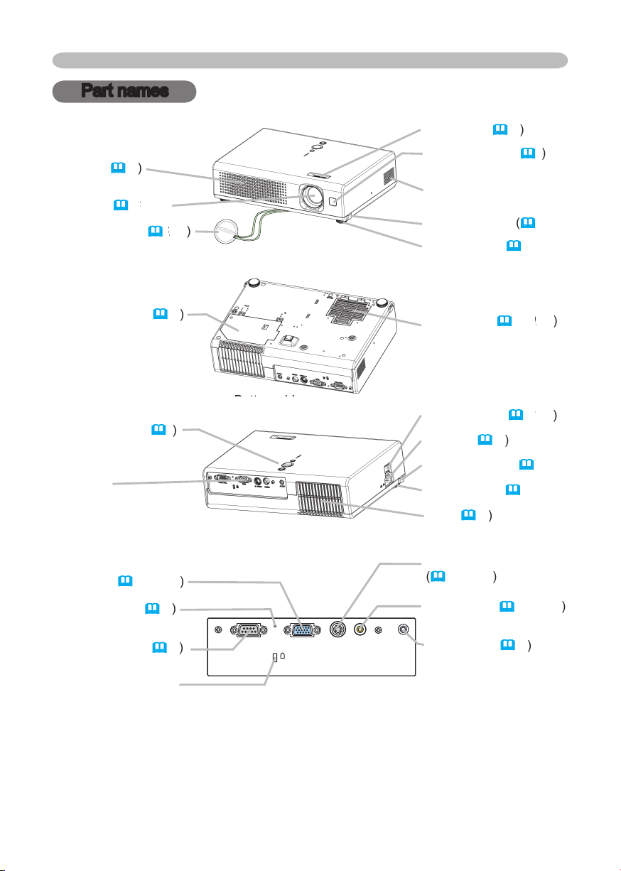
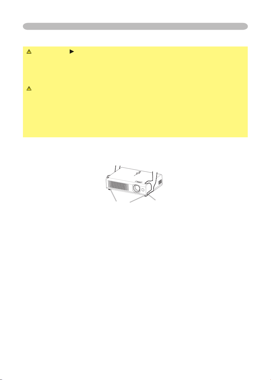
Part names
Lens (
1
6
, 45
6, 456
)
Lens cover (
6
, 16
6, 166
)
Filter cover (
9, 1
0
, 43
0, 430
)
(Air fi lter and intake vent
are inside.)
Elevator button
(
12
)
Elevator foot (
12
)
Remote sensor (
8
)
Focus ring (
1
9
)
Vent (
10
)
AC inlet (
1
5
)
Power switch (
1
6
, 17
6, 176
)
Elevator button (
12
)
S-VIDEO port
(
1
4, 18, 19
)
VIDEO port (
1
4, 18, 19
)
CONTROL port (
1
4
)
Part names
Projector
Lamp cover (
42
)
(Lamp unit is inside.)
Elevator foot (
12
)
Bottom side
Bottom side
Speaker
Front-Right side
Rear-Left side
Control buttons (
5
)
Ports
(See below.)
Vent (
10
)
Ports
AUDIO port (
1
4
)
Restart switch (
17
)
RGB port (
1
4, 18, 19
)
Kensington lock slot
5
STANDBY/ON
INPU
T
MENU
LAMP
TE MP
PO WER
VIDEO
RG
B
SEARC
H
FREEZE
OFF
ON
MAGNIFY
ASPECT AUTO
BLAN
K
MUTE
VOLUME
KEYSTONE
POSITION
ES
C
ENTE
R
MENU
RESE
T
ZOOM
+
-
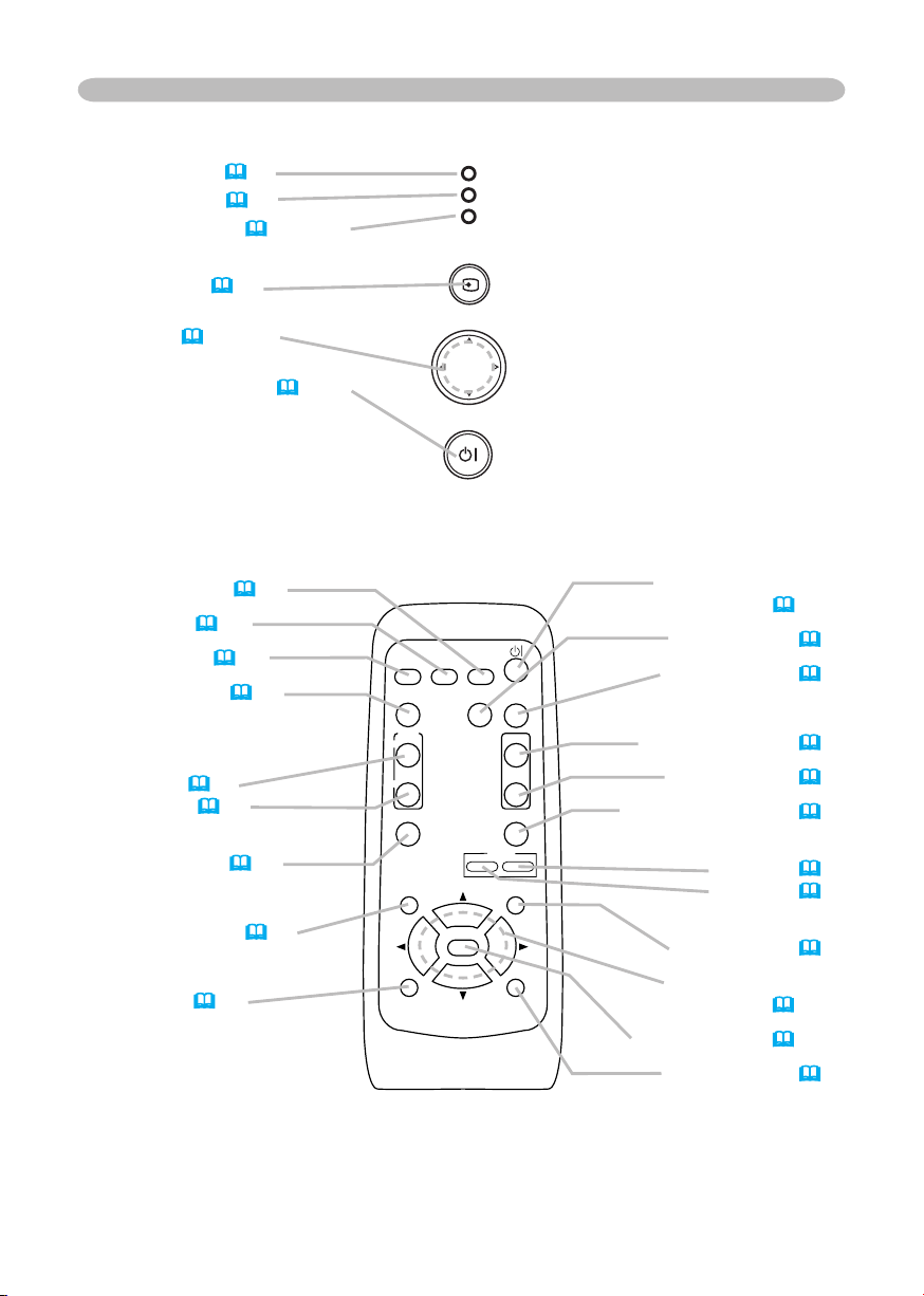
Part names
LAMP indicator (
48)
TEMP indicator (
48)
POWER indicator (
16, 17, 48)
INPUT button (
18)
Cursor buttons
▲,▼,◄,► (
18~40)
STANDBY/ON button (
16, 17)
Controls
Remote control
SEARCH button (
19)
RGB button (
18)
VIDEO button (
18)
ASPECT button (
19)
MAGNIFY
ON button (
21)
OFF button (
21)
FREEZE button (
21)
POSITION button (
20)
ESC button (
24)
STANDBY/ON button
(
16, 17)
AUTO button (
20)
BLANK button (
21)
VOLUME button (
18)
MUTE button (
18)
KEYSTONE button (
20)
Zoom
+ button (
19)
- button (
19)
MENU button (
22)
Menu cursor buttons
▲,▼,◄,►(
18~40)
ENTER button (
18~40)
RESET button (
24)
6
Preparations
Fastening the lens cover
WARNING
►
Do not fasten the lens cover during use or immediately after
use. Handling while the projector is in a high temperature could cause a burn
and/or malfunction to the projector. Before operating, make sure that the power
switch is off, that the power cord is not plugged in, and that the projector is cool
adequately.
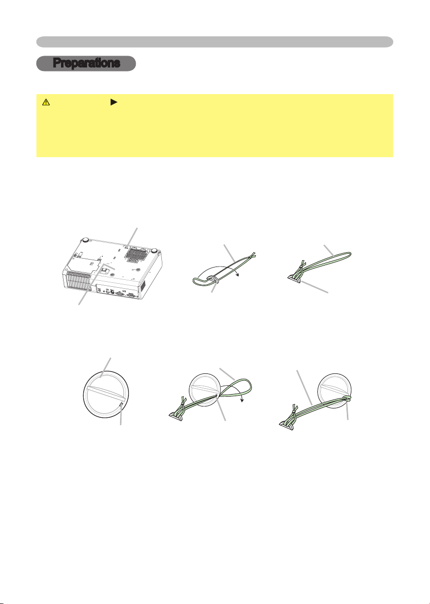
To avoid losing, please fasten the lens cover to the projector using the strap.
1.
Slowly turn over the projector, so that the bottom is facing up.
2.
Fix the strap to the strap ring of projector.
3.
Fix the strap to the strap ring of lens cover.
4.
Attach the lens cover to the lens of projector, and slowly turn over the
projector, so that the top is facing up.
Preparations
Strap ring
Projector (Bottom side)
Strap
Strap ring
Strap
Strap ring
(1)
(2)
Lens cover
Strap
Strap ring
Strap
Strap ring
(1)
(2)
Strap ring
7
Preparations
Putting batteries
WARNING
►
Always handle the batteries with care and use them only as
directed. Improper use may result in battery explosion, cracking or leakage,
which could result in fi re, injury and/or pollution of the surrounding environment.
• Be sure to use only the batteries specifi ed. Do not use batteries of different
types at the same time. Do not mix a new battery with used one.
• Make sure the plus and minus terminals are correctly aligned when loading a
battery.
• Keep a battery away from children and pets.
• Do not recharge, short circuit, solder or disassemble a battery.
• Do not allow a battery in a fi re or water. Keep batteries in a dark, cool and dry
place.
• Do not give the battery a physical impact.
• If you observe a leakage of a battery, wipe out the fl ower and then replace
a battery. If the fl ower adheres your body or clothes, rinse well with water
immediately.
• Obey the local laws on disposing a battery.
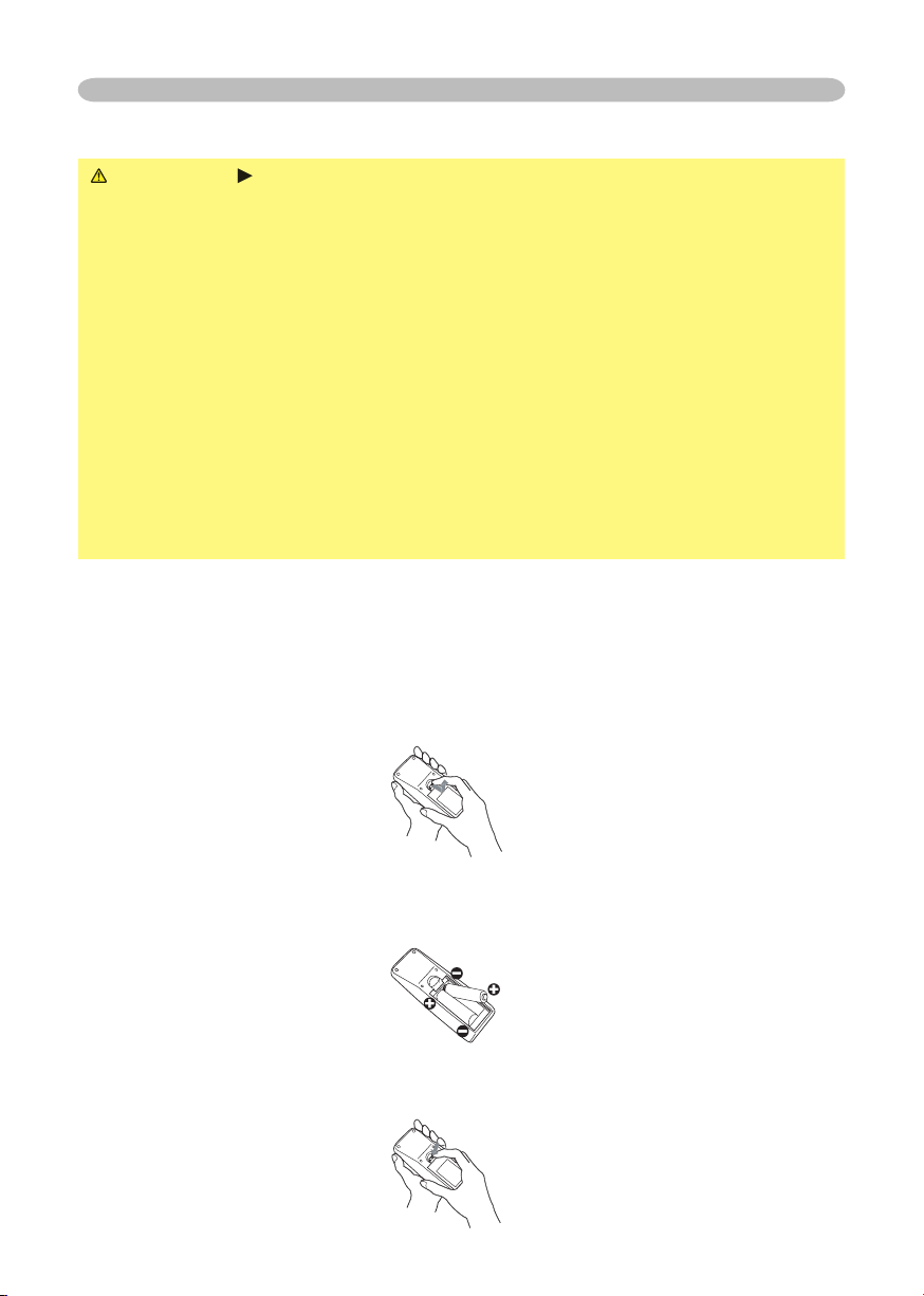
To use the remote control, please load the batteries. Whenever the remote control
starts to malfunction, replace the batteries. If you won’t use the remote control for
an extended period, remove the batteries from the remote control and store them
in a safe place.
1.
Remove the battery cover.
Slide back and remove the battery cover in the direction of the arrow.
2.
Take old batteries out and/or put new batteries in.
When putting in batteries, align and insert the two AA batteries according to
their plus and minus terminals as indicated in the remote control.
3.
Close the battery cover.
Replace the battery cover in the direction of the arrow and snap it back into
place.
8
Preparations
Using the remote control
CAUTION
►
Be careful in handling the remote control. Incorrect handling
could cause damage or malfunction.
• Do not drop or otherwise expose the remote control to physical impact.
• Do not get the remote control wet or place it on wet objects.
• Remove the batteries from the remote control and store them in a safe place if
you won’t be using the remote control for an extended period.
• Replace the batteries whenever the remote control starts to malfunction.
• When strong lights such as direct sunlight or light from an extremely close
range (such as from an inverter fl uorescent lamp) hit the projector’s remote
sensor, the remote control may not function correctly. Adjust the direction of the
projector to keep light from directly hitting the projector’s remote sensor.
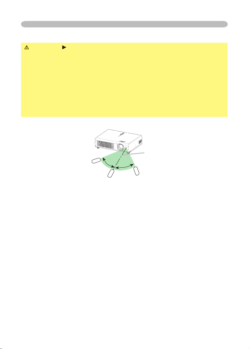
The remote control works with the projector’s remote sensor.
• The range of the remote sensor is 3 meters with a 60 degree range (30 degrees
to the left and right of the remote sensor).
• Also a remote signal refl ected in the screen etc. may be available. If it is diffi cult
to send a remote signal to the sensor directly, please try.
• Since the remote control uses infrared light to send signals to the projector
(Class1 LED), be sure to use the remote control in an area free from obstacles
that could block the remote control’s output signal to the projector.
approx. 3 meters
30º
30º
9
Preparations
About the fi lter cover for bottom-up use
WARNING
►Do not replace the fi lter cover and/or air fi lter during use or
immediately after use. Handling while the projector is in a high temperature
could cause a burn and/or malfunction to the projector. Before operating, make
sure that the power switch is off, that the power cord is not plugged in, and that
the projector is cool adequately.
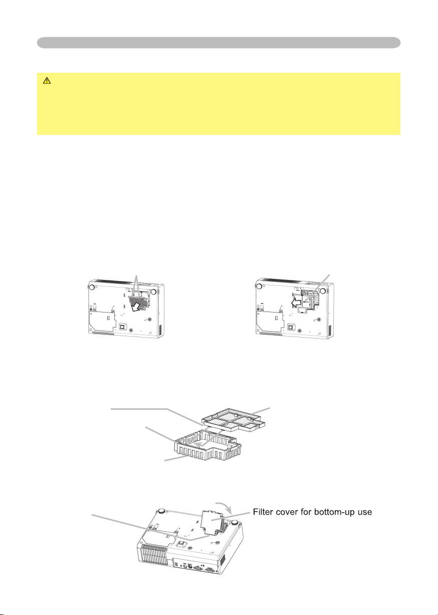
When the projector is installed bottom up, please use the accessory fi lter cover
for bottom-up use. It is higher than usual fi lter cover, to keep the space for intake
ventilation. Please change in the following procedure.
1.
Disconnect all the connectors and adapters that were connected to the
projector’s ports. Then slowly turn the projector so that the lens-side is facing
up. Please be careful for a projector not to fall. While the projector is placed
lens-side up, hold the projector.
2.
Remove the fi lter cover and the air fi lter. Hold the knobs while pulling out it.
3.
Slowly turn the projector so that the bottom is facing up.
4.
Set a new or cleaned air fi lter to the fi lter cover for bottom-up use. Make the
claws slide along the rail, and set the air fi lter into place.
5.
Interlocking the tabs, snap the fi lter cover for bottom-up use into place.
Air fi lter’s knob
Claws
Filter cover’s knob
Rail of air fi lter
Filter cover for bottom-up use
Air fi lter (New or cleaned)
Filter cover for bottom-up use
(with an air fi lter)
Tabs

10
Setting up
Setting up
WARNING
►
Place the projector in a stable position horizontally. A fall or
a turnover could cause an injury and/or damage to the projector. Then using
damaged projector could result in a fi re and/or an electric shock.
• Don’t place the projector on an unstable, slant or vibrant surface such as a
wobbly or inclined stand.
• Do not place the projector in the side/front/rear-up position, except care of the
air fi lter.
• For the projector installed bottom-up, use the accessory fi lter cover for bottom-
up use. And in the case of a ceiling installation or the like, contact your dealer
before installation.
►Place the projection in a cool place, and pay attention enough to ventilation.
The high temperature of the projector could cause a fi re, a burn and/or
malfunction to the projector.
• Don’t stop up, block and cover the projector's vents.
• Keep a space of 30 cm or more between the sides and other objects such as
walls.
• Don’t place the projector on a metallic thing or anything weak in heat.
• Don’t place the projector on a carpet, cushion or bedding.
• Don’t place the projector in direct sunlight or near a hot object such as heater.
• Put nothing about lens and vents of the projector. Put nothing on the projector.
• Put nothing that is sucked or sticks to the bottom of projector. This projector
has some intake vents also on the bottom.
►Do not place the projector on the place that gets wet. Damping the projector
or inserting liquid in the projector could cause a fi re, an electric shock and/or
malfunction to the projector.
• Don’t place the projector in a bathroom or the outdoors.
• Put nothing containing the liquid near the projector.
CAUTION
►Avoid a smoky, humid or dusty place. Placing the projector
in such place could cause a fi re, an electric shock and/or malfunction to the
projector.
•
Don’t place the projector near a humidifi er, a smoking space or a kitchen.
•
Put nothing containing the liquid near the projector.
►Adjust the direction of the projector to keep light from directly hitting the
projector's remote sensor.
11
Setting up
(a) Screen size
[inch (m)]
[inch (m)]
[inch (m)]
(b) Projection distance
[m (inch)]
[m (inch)]
[m (inch)]
(c) Screen height [cm (inch)]
(c) Screen height [cm (inch)]
(c) Screen height [cm (inch)]
(c) Screen height [cm (inch)]
(c) Screen height [cm (inch)]
down
up
up
up
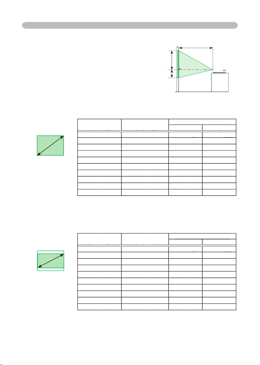
40
(1.0)
1.3
(53)
8.7
(3)
(3)
52.3
(21)
(21)
50
(1.3)
1.7
(66)
10.9
(4)
65.3
(26)
60
(1.5)
2.0
(80)
13.1
(5)
78.4
(31)
70
(1.8)
2.4
(93)
15.2
(6)
91.4
(36)
80
(2.0)
2.7
(107)
17.4
(7)
104.5
(41)
90
(2.3)
3.1
(121)
19.6
(8)
117.6
(46)
100
(2.5)
3.4
(134)
21.8
(9)
130.6
(51)
120
(3.0)
4.1
(161)
26.1
(10)
156.8
(62)
150
(3.8)
5.1
(202)
32.7
(13)
195.9
(77)
200
(5.1)
6.8
(269)
43.5
(17)
261.3
(103)
(a) Screen size
[inch (m)]
[inch (m)]
[inch (m)]
(b) Projection distance
[m (inch)]
[m (inch)]
[m (inch)]
(c) Screen height [cm (inch)]
(c) Screen height [cm (inch)]
(c) Screen height [cm (inch)]
(c) Screen height [cm (inch)]
(c) Screen height [cm (inch)]
down
up
up
up
40
(1.0)
1.5
(58)
1.2
(0)
(0)
48.6
(19)
(19)
50
(1.3)
1.8
(72)
1.5
(1)
60.8
(24)
60
(1.5)
2.2
(87)
1.8
(1)
72.9
(29)
70
(1.8)
2.6
(102)
2.1
(1)
85.1
(34)
80
(2.0)
3.0
(117)
2.4
(1)
97.2
(38)
90
(2.3)
3.3
(131)
2.7
(1)
109.4
(43)
100
(2.5)
3.7
(146)
3.0
(1)
121.6
(48)
120
(3.0)
4.5
(176)
3.6
(1)
145.9
(57)
150
(3.8)
5.6
(220)
4.4
(2)
182.3
(72)
200
(5.1)
7.5
(294)
5.9
(2)
243.1
(96)
Arrangement
Refer to the illustrations and tables below
to determine the screen size and projection
distance.
The values shown in the table are calculated
(±3%) for a full size screen: 1024x768
At 16:9 screen
At 4:3 screen
4:3
(a)
16:9
(a)
(c) up
(c) down
(b)
12
Adjusting the projector's elevator
WARNING
►
Do not adjust the projector’s elevator during use or
immediately after use. Handling while the projector is in a high temperature
could cause a burn and/or malfunction to the projector. Before operating, make
sure that the power switch is off, that the power cord is not plugged in, and that
the projector is cool adequately.
CAUTION
►If you press the elevator button without holding the projector,
the projector might crash down, overturn, smash your fi ngers and possibly
result in malfunction.
To prevent damaging the projector and injuring yourself,
always hold the projector whenever using the elevator buttons to adjust the
elevator feet.
►Except for inclining by the elevator feet adjustment, place the projector
horizontally.
You can use the elevator feet to make adjustments if the surface on which you
need to set the projector is uneven or if you otherwise need to adjust the angle of
projection. The adjustment range of the elevator feet is 0 to 9 degrees.
1.
Press and hold in the elevator buttons while holding the projector.
The elevator buttons and the elevator feet are on the both sides.
2.
Raise or lower the projector to the desired height and then release the
elevator buttons.
When you release the elevator buttons, the elevator feet will lock into position.
3.
As necessary, you can also fi nely adjust the height of the projector by twisting
the elevator feet by hand.
Setting up
Elevator feet
Elevator button

13
Setting up
Connecting your devices
CAUTION
►Turn off all devices prior to connecting them to the projector.
Attempting to connect a live device to the projector may generate extremely
loud noises or other abnormalities that may result in malfunction and/or damage
to the device and/or projector
.
►Use the accessory cable or a designated-type cable for the connection.
Some cables have to be used with core set. A too long cable may cause a
certain picture degradation. Please consult with your dealer for details. For
cables that have a core only at one end, connect the core to the projector.
►Make sure that you connect devices to the correct port. Incorrect connection
may result in malfunction and/or damage to the device and/or projector.
NOTE
•
Whenever attempting to connect a laptop computer to the projector,
be sure to activate the laptop’s RGB external image output (set the laptop to CRT
display or to simultaneous LCD and CRT display). For details on how this is done,
please refer
to the instruction manual of the corresponding laptop computer.
•
Secure the screws on the connectors and tighten.
•
Some computers may have multiple display screen modes. Use of some of
these modes wi
ll not be possible with this projector.
• For some RGB signal modes, the optional Mac adapter is necessary.
• When the image resolution is changed on a computer, depending on an input,
automatic adjust function may take some time and may not be completed. In
this case, you may not be able to see a check box to select “Yes/No” for the
new resolution on Windows. Then the resolution will go back to the original.
It might be recommended to use other CRT or LCD monitors to change the
resolution.
About Plug-and-Play capability
Plug-and-Play is a system composed of the computer, its operating system and
peripheral equipment (i.e. display devices). This projector is compatible with
VESA DDC 2B. Plug-and-Play can be achieved by connecting this projector to
computers that are VESA DDC (display data channel) compatible.
• Please take advantage of this function by connecting the accessory RGB
cable to the RGB port (DDC 2B compatible). Plug-and-Play may not work
properly if any other type of connection is attempted.
• Please use the standard drivers in your computer as this projector is a
Plug-and-Play monitor.
14
K
K
K
K
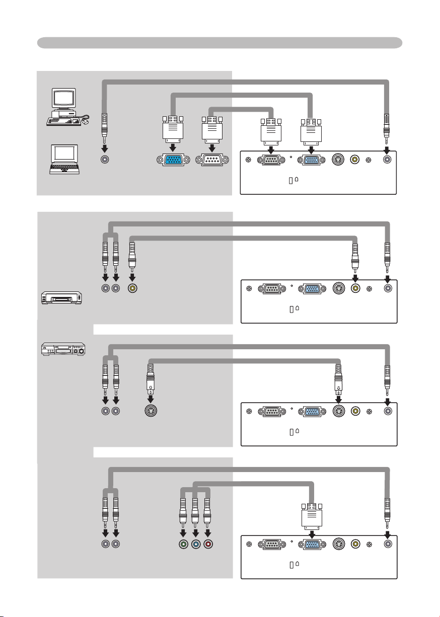
Setting up
Audio out
S-Video out
RS-232C
RGB out
Examples of connection with a computer
Examples of connection with a VCR/DVD player
Audio cable (stereo mini)
RGB cable
Video out
Audio out
Audio cable (stereo mini)
Audio cable (stereo mini)
Audio out
Component video cable
Component video cable
Audio out
Audio cable (stereo mini)
Video cable
RS-232C cable
S-Video cable
Component video out
15
Connecting power supply
WARNING
►
Please use extra caution when connecting the power cord as
incorrect or faulty connections may result in fi re and/or electrical shock.
• Only use the power cord that came with the projector. If it is damaged, contact
your dealer to newly get correct one.
• Only plug the power cord into an outlet rated for use with the power cord's
specifi ed voltage range.
• Never modify the power cord. Never attempt to defeat the ground connection
of the three-pronged plug.
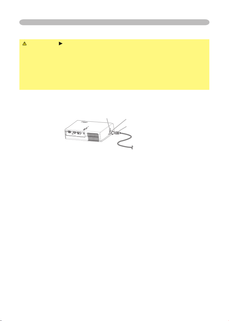
Before connecting, make sure that the power switch is the OFF position (pressed
the side marked “O”).
1.
Connect the connector of the power cord to the AC inlet of the projector.
2.
Firmly plug the power cord's plug into the outlet.
Setting up
Power switch
AC inlet
Connector of the power cord
16
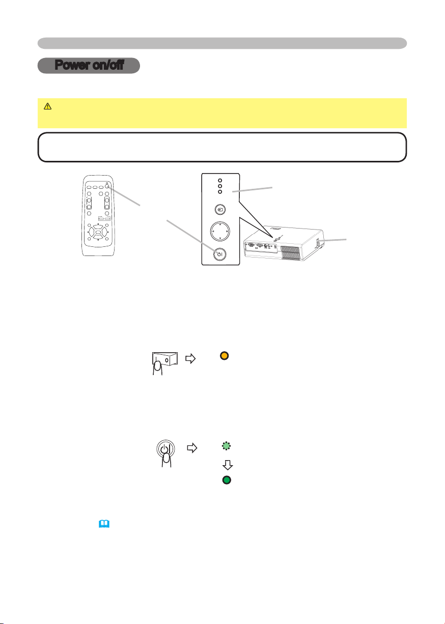
Power on/off
Power on/off
Turning on the power
WARNING
►
When the power is on, a strong light is emitted. Do not look
into the lens or vents of the projector.
NOTE • Turn the power on in right order. Please power on the projector before
the connected devices.
STANDBY/ON
button
1.
Make sure that the power cord is firmly and correctly connected to the
projector and outlet.
2.
Open the lens cover, and set the power switch to the ON position.
The power indicator will light to solid orange. Then wait several seconds
because buttons may not function for these several seconds.
3.
Press the STANDBY/ON button on the projector or remote control.
The projector lamp will light up and the POWER indicator will begin blinking
green. When the power is completely on, the indicator will stop blinking and
light green.
To display the picture, select an input signal according to the section "Selecting an
input signal"
(
18)
.
POWER
(Solid orange)
POWER
(Blinking green)
POWER
(Solid green)
VIDEO
RG
B
SEARC
H
FREEZE
OFF
ON
MAGNIFY
ASPECT AUT
O
BLAN
K
MUTE
VOLUME
KEYST
ONE
POSITION
ES
C
ENTE
R
MENU
RESE
T
ZOOM
+
-
POWER indicator
Power switch
STAN D BY /O
N
IN PU
T
ME NU
LA M
P
TE M P
PO W E R
17
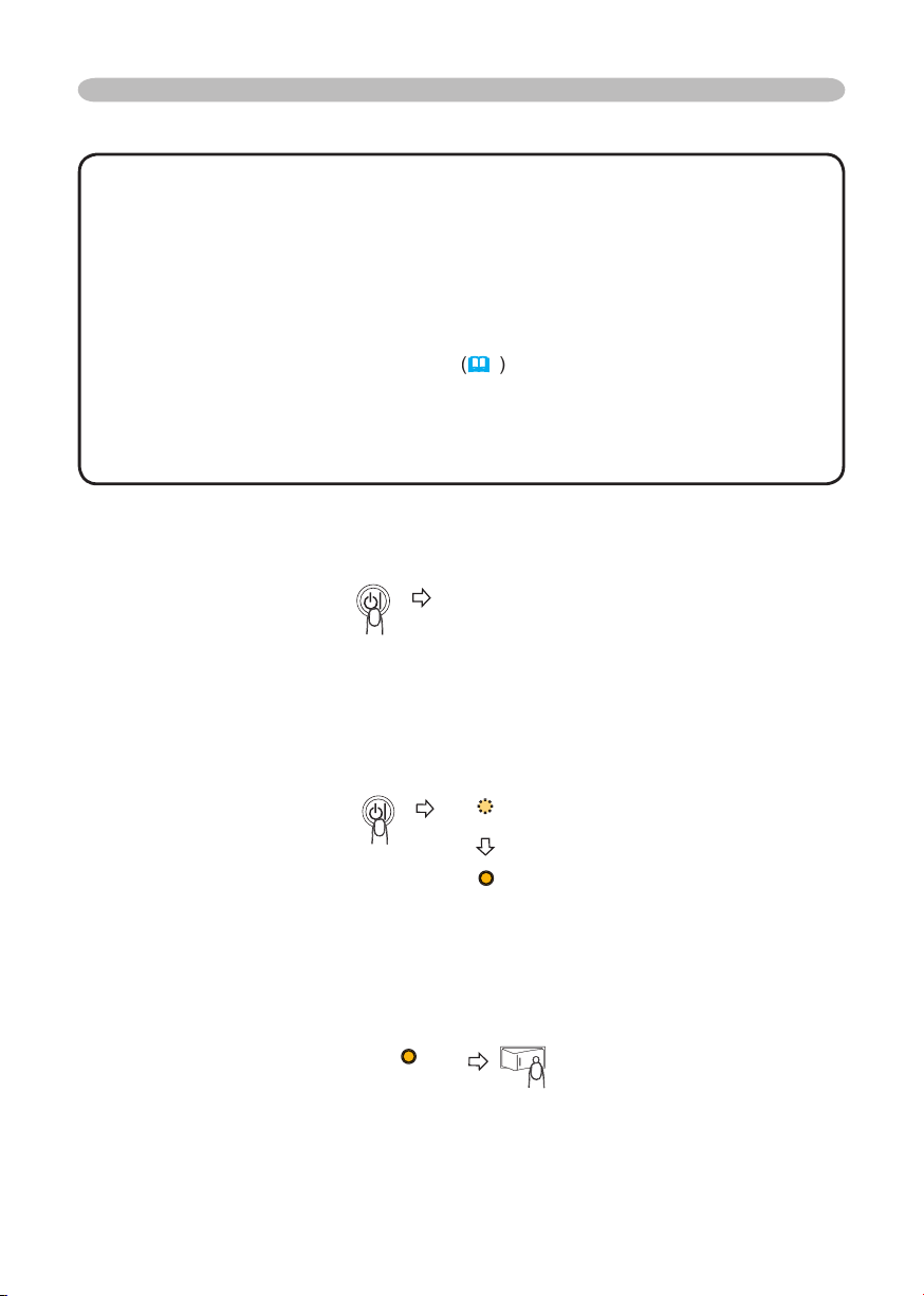
Turning off the power
NOTE
•
Turn the power off in right order. Please power off the projector after the
connected devices.
•
Except for an emergency, whenever you turn the projector off, obey the procedure
of the following “Turning off the power”, and do not disconnect the power cord until the
procedure is completed. Neglect causes a damage of the electrode and un-lighting of
the lamp.
•
This Projector is controlled by an internal microprocessor. Under certain exceptional
circumstances, the projector may not operate correctly even for turning off the power. In
such a case, please push the restart switch
(
4
)
by using a pin or similar. After making
sure that the power indicator lights to solid orange, set the power switch to the OFF
position. Only push the restart switch in these exceptional instances.
•
When a power supply is shut off with a power failure or the restart switch, before
turning on again, make the projector cool down at least 10 minutes without operating.
1.
Press the STANDBY/ON button on the projector or remote control.
The message "Power off?" will appear on the screen for approximately 5
seconds.
2.
Press the STANDBY/ON button on the projector or remote control again while the
message is visible.
The projector lamp will go off, and the POWER indicator will begin blinking orange.
Then the POWER indicator will stop blinking and light to solid orange when the
lamp cooling is complete.
3.
Make sure that the power indicator lights to solid orange, set the power switch
to the OFF position. The POWER indicator will go off.
Do not set the power switch to the OFF position while the POWER indicator is
green or blinking.
4.
Close the lens cover. For safety purposes, disconnect the power cord if the
projector is not to be used for prolonged periods of time.
Power on/off
Power off?
POWER
(Blinking orange)
POWER
(Solid orange)
POWER
(Solid orange)
18
Operating
Operating
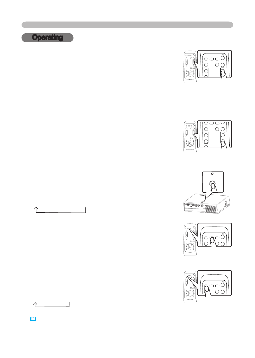
Adjusting the volume
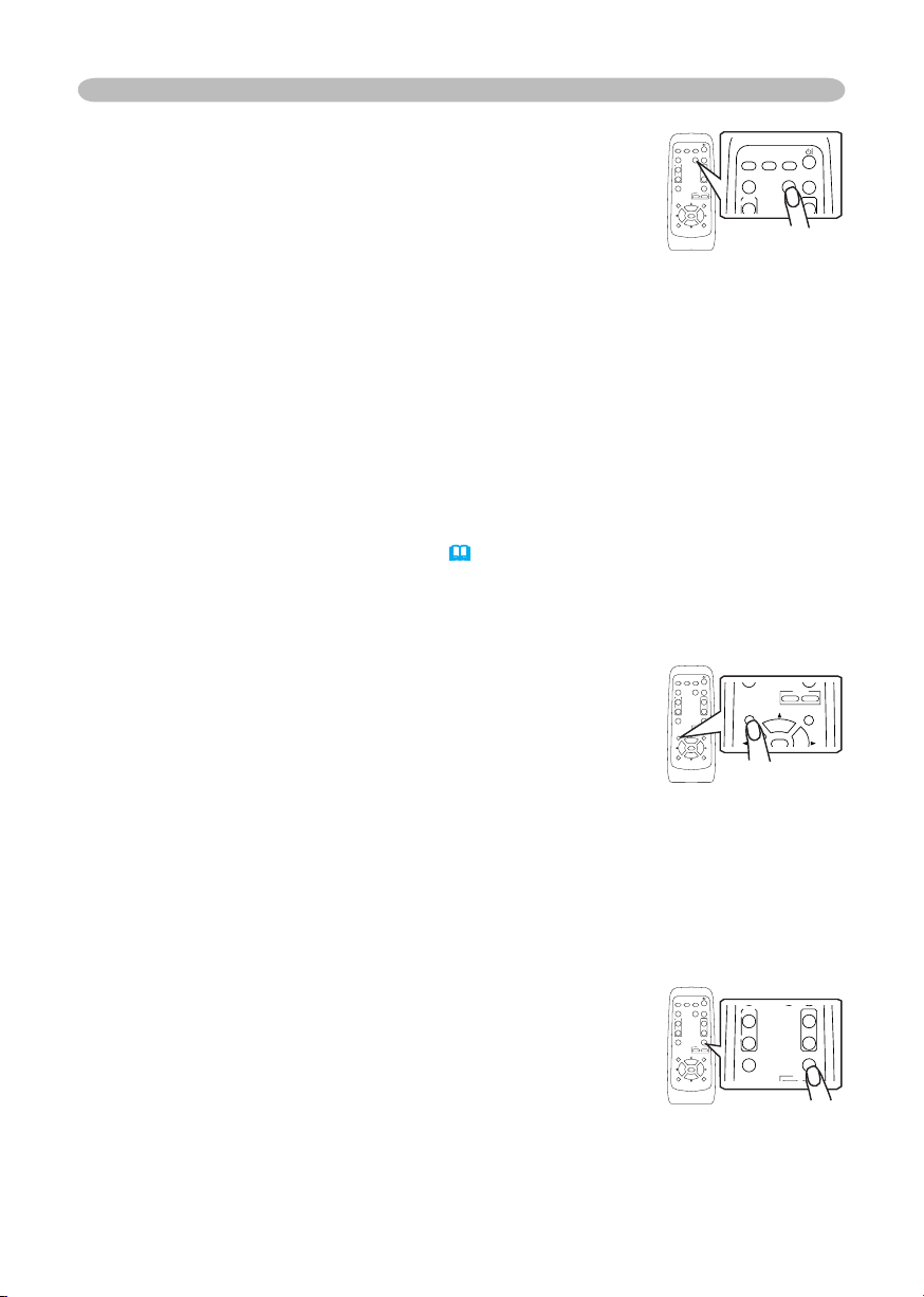
1.
Press the VOLUME button on the remote control.
A dialog will appear on the screen to aid you in adjusting
the volume.
2.
Use the cursor buttons ▲/▼ to adjust the volume.
To close the dialog and complete the operation, press the VOLUME button
again. Even if you don’t do anything, the dialog will automatically disappear
after a few seconds.
Temporarily muting the sound
1.
Press the MUTE button on the remote control.
A dialog will appear on the screen indicating that you
have muted the sound.
To restore the sound, press the MUTE button or
VOLUME button. Even if you don’t do anything, the
dialog will automatically disappear after a few seconds.
Selecting an input signal
1.
Press the INPUT button on the projector.
Each time you press the button, the projector switches
its input port as below.
RGB
S-VIDEO
VIDEO
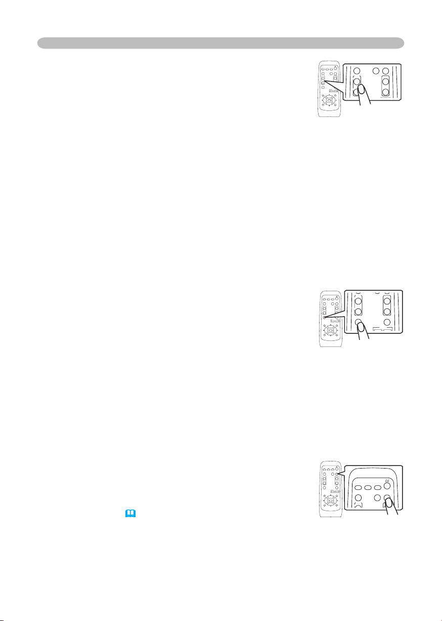
1.
Press the RGB button on the remote control to select
the RGB port.
1.
Press the VIDEO button on the remote control to select
an input port for video signal.
Each time you press the button, the projector switches
its video input port as below.
S-VIDEO
VIDEO
● When the TURN ON is selected to the item AUTO SEARCH of OPTION menu
(
38)
, the projector selects the S-VIDEO port at first. If no input is detected at the
S-VIDEO port, projector will check the VIDEO port automatically.
VIDEO
RG
B
SEARC
H
FREEZE
OFF
ON
MAGNIFY
ASPECT AUTO
BLAN
K
MUTE
VOLUME
KEYSTONE
POSITION
ES
C
ENTE
R
MENU
RESE
T
ZOOM
+
-
VIDEO
RG
B
SEARC
H
FREEZE
OFF
ON
MAGNIFY
ASPECT AUTO
BLAN
K
MUTE
VOLUME
KEYSTONE
POSITION
ES
C
ENTE
R
MENU
RESE
T
ZOOM
+
-
VIDEO
RG
B
SEARC
H
FREEZE
OFF
ON
MAGNIFY
ASPECT AUTO
BLAN
K
MUTE
VOLUME
KEYSTONE
POSITION
ES
C
ENTE
R
MENU
RESE
T
ZOOM
+
-
VIDEO
RG
B
SEARC
H
FREEZE
OFF
ON
MAGNIFY
ASPECT AUTO
BLAN
K
MUTE
VOLUME
KEYSTONE
POSITION
ES
C
ENTE
R
MENU
RESE
T
ZOOM
+
-
STAN DBY /O N
IN PU
T
ME NU
LA MP
TE M P
PO W E R
VIDEO
RG
B
SEARC
H
FREEZE
OFF
ON
MAGNIFY
ASPECT AUTO
BLAN
K
MUTE
VOLUME
KEYSTONE
POSITION
ES
C
ENTE
R
MENU
RESE
T
ZOOM
+
-
VIDEO
RG
B
SEARC
H
FREEZE
OFF
ON
MAGNIFY
ASPECT AUT
O
BLAN
K
MUTE
VOLUME
KEYST
ONE
POSITION
ES
C
ENTE
R
MENU
RESE
T
ZOOM
+
-
VIDEO
RG
B
SEARC
H
FREEZE
OFF
ON
MAGNIF
Y
ASPECT AUT
O
BLAN
K
MUTE
VOLUME
KEYSTONE
POSITION
ES
C
ENTE
R
MENU
RESE
T
ZOOM
+
-
VIDEO
RG
B
SEARC
H
FREEZE
OFF
ON
MAGNIFY
ASPECT AUT
O
BLAN
K
MUTE
VOLUME
KEYST
ONE
POSITION
ES
C
ENTE
R
MENU
RESE
T
ZOOM
+
-
19
Operating
Adjusting the zoom (magnifying power)
1.
Press the ZOOM +/- button on the remote control.
A dialog will appear on the screen to aid you in
adjusting the zoom.
2.
Use the ZOOM buttons +/- to adjust the zoom.
To close the dialog and complete this operation, don’t
perform operation for a few seconds.
Searching an input signal
1.
Press the SEARCH button on the remote control.
The projector will begin to check its input ports in order
to find any input signals.
Then when an input is found, the projector will stop
searching and display the image. If no signal is found,
the projector will return to the state selected before the
operation.
RGB
S-VIDEO
VIDEO
VIDEO
RG
B
SEARC
H
STANDBY/ON
FREEZE
OFF
ON
MAGNIFY
ASPECT AUTO
BLAN
K
HOME
PAGE UP
PAGE DOWN
END
MUTE
VOLUME
KEYSTONE
POSITION
ES
C
ENTE
R
MENU
RESE
T
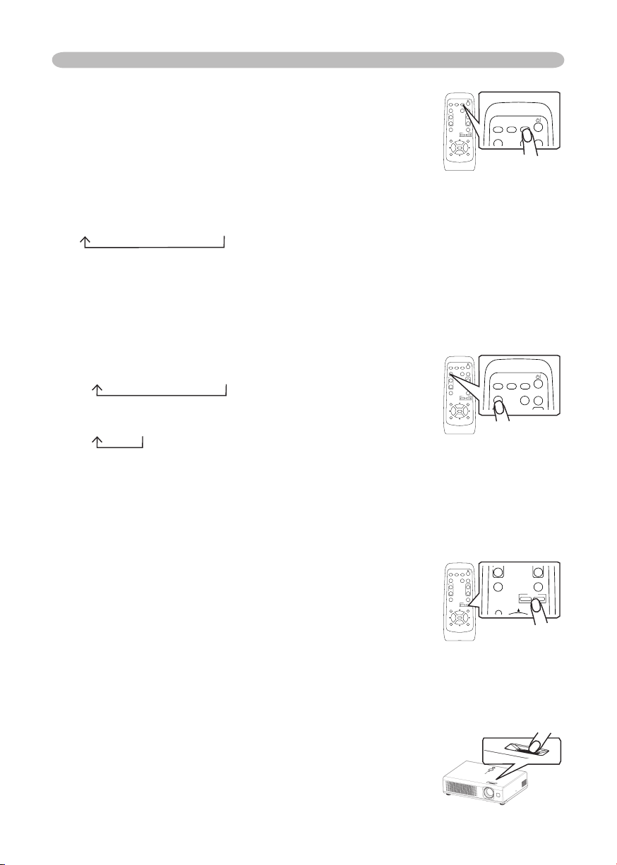
Selecting an aspect ratio
1.
Press the ASPECT button on the remote control.
Each time you press the button, the projector switches the modes for aspect
ratio in turn.
At a RGB signal
NORMAL
4:3
16:9
At a video signal /no signal
4:3
16:9
● The NORMAL mode keeps the original aspect ratio of the signal.
● At a HDTV component video signal of 1125i (1080i) or 750p (720p), only 16:9
mode can be selected.
● Performing the automatic adjustment initializes the aspect ratio setting.
Adjusting the focus
1.
Use the focus ring to focus on the picture.
VIDEO
RG
B
SEARC
H
FREEZE
OFF
ON
MAGNIF
Y
ASPECT AUTO
BLAN
K
MUTE
VOLUME
KEYSTONE
POSITION
ES
C
ENTE
R
MENU
RESE
T
ZOOM
+
-
VIDEO
RG
B
SEARC
H
FREEZE
OFF
ON
MAGNIFY
ASPECT AUT
O
BLAN
K
MUTE
VOLUME
KEYST
ONE
POSITION
ES
C
ENTE
R
MENU
RESE
T
ZOOM
+
-
VIDEO
RG
B
SEARC
H
FREEZE
OFF
ON
MAGNIFY
ASPECT AUT
O
BLAN
K
MUTE
VOLUME
KEYSTONE
POSITION
ES
C
ENTE
R
MENU
RESE
T
ZOOM
+
-
VIDEO
RG
B
SEARC
H
FREEZE
OFF
ON
MAGNIFY
ASPECT AUT
O
BLAN
K
MUTE
VOLUME
KEYST
ONE
POSITION
ES
C
ENTE
R
MENU
RESE
T
ZOOM
+
-
VIDEO
RG
B
SEARC
H
FREEZE
OFF
ON
MAGNIFY
ASPECT AUTO
BLAN
K
MUTE
VOLUME
KEYSTONE
POSITION
ES
C
ENTE
R
MENU
RESE
T
ZOOM
+
-
VIDEO
RG
B
SEARC
H
FREEZE
OFF
ON
MAGNIFY
ASPECT AUT
O
BLAN
K
MUTE
VOLUME
KEYSTONE
POSITION
ES
C
ENTE
R
MENU
RESE
T
ZOOM
+
-
20
Operating
Correcting the keystone distortions
1.
Press the KEYSTONE button on the remote control.
A dialog will appear on the screen to aid you in correcting
the distortion.
2.
Use the cursor buttons ▲/▼ to correct the distortion.
To close the dialog and complete this operation, press
the KEYSTONE button again. Even if you don’t do anything, the dialog will
automatically disappear after a few seconds.
● This function may not be work well with some input.
● The adjustable range for correcting will vary among inputs.
Using the automatic adjustment feature
1.
Press the AUTO button on the remote control.
At a RGB signal
The vertical position, the horizontal position, the clock
phase and horizontal size will be automatically adjusted.
And the aspect ratio will be automatically selected.
Make sure that the application window is set to its maximum size prior to
attempting to use this feature. A dark picture may still be incorrectly adjusted.
Use a bright picture when adjusting.
At a video signal or s-video signal
The signal type mode best suited for the respective input signal and the aspect
ratio will be selected automatically. And the vertical position, the horizontal
position will be automatically adjusted.
At a component video signal
The vertical position, the horizontal position and the clock phase will be
automatically adjusted. And the aspect ratio will be automatically selected.
This function is available only when the AUTO mode is selected to the item
VIDEO FORMAT of INPUT menu
(
32)
. For a component video signal, the
signal type is identified automatically, independently of this function.
● The automatic adjustment operation requires approximately 10 seconds. Also
please note that it may not function correctly with some input.
Adjusting the position
1.
Press the POSITION button on the remote control.
The “POSITION” indication will appear on the screen.
2.
Use the cursor buttons ▲/▼/◄/► to adjust the picture
position.
When you want to reset the operation, press the RESET button on the remote
control during the operation.
To complete this operation, press the POSITION button again. Even if you don’t
do anything, the dialog will automatically disappear after a few seconds.
● When this function is performed at a video signal, a certain extra such as a line
may appear outside a picture.
VIDEO
RG
B
SEARC
H
FREEZE
OFF
ON
MAGNIFY
ASPECT AUTO
BLAN
K
MUTE
VOLUME
KEYSTONE
POSITION
ES
C
ENTE
R
MENU
RESE
T
ZOOM
+
-
VIDEO
RG
B
SEARC
H
FREEZE
OFF
ON
MAGNIFY
ASPECT AUTO
BLAN
K
MUTE
VOLUME
KEYSTONE
POSITION
ES
C
ENTE
R
MENU
RESE
T
ZOOM
+
-
VIDEO
RG
B
SEARC
H
FREEZE
OFF
ON
MAGNIFY
ASPECT AUTO
BLAN
K
MUTE
VOLUME
KEYSTONE
POSITION
ES
C
ENTE
R
MENU
RESE
T
ZOOM
+
-
VIDEO
RG
B
SEARC
H
FREEZE
OFF
ON
MAGNIFY
ASPECT AUTO
BLAN
K
MUTE
VOLUME
KEYSTONE
POSITION
ES
C
ENTE
R
MENU
RESE
T
ZOOM
+
-
VIDEO
RG
B
SEARC
H
FREEZE
OFF
ON
MAGNIFY
ASPECT AUTO
BLAN
K
MUTE
VOLUME
KEYSTONE
POSITION
ES
C
ENTE
R
MENU
RESE
T
ZOOM
+
-
VIDEO
RG
B
SEARC
H
FREEZE
OFF
ON
MAGNIFY
ASPECT AUTO
BLAN
K
MUTE
VOLUME
KEYSTONE
POSITION
ES
C
ENTE
R
MENU
RESE
T
ZOO
M
+
-
21
Operating
Freezing the screen
1.
Press the FREEZE button on the remote control.
The “FREEZE” indication will appear on the screen, and
the projector will enter the FREEZE mode.
To exit the FREEZE mode and restore the screen to normal,
press the FREEZE button again.
● The projector automatically exits the FREEZE mode when the input signal
changes, or when one of the projector’s buttons or the remote control buttons
of STANDBY/ON, SEARCH, RGB, VIDEO, BLANK, AUTO, ASPECT, VOLUME,
MUTE, KEYSTONE, POSITION and MENU is pressed.
● If the projector continues projecting a still image for long time, the LCD panel
might possibly be printed. Do not leave the projector in FREEZE mode for too
long.
Using the partial magnify feature
1.
Press the ON button of MAGNIFY on the remote control.
The “MAGNIFY” indication will appear on the screen
(although the indication will disappear after several
seconds with no operation.), and the projector will enter the
MAGNIFY mode.
2.
Use the cursor buttons ▲/▼ to adjust the zoom level.
To move the zoom area, press the POSITION button in the MAGNIFY mode,
then use the cursor buttons ▲/▼/◄/►. And to finalize the zoom area, press
the POSITION button again.
To exit the MAGNIFY mode and restore the screen to normal, press the OFF
button of MAGNIFY on the remote control.
● The projector automatically exits the MAGNIFY mode when the input signal
changes, or when an operation of changing the display condition (automatic
adjustment, etc.) is executed.
● Although the keystone distortion condition may vary in the MAGNIFY mode, it
will be restored when the projector exit the MAGNIFY mode.
Temporarily blanking the screen
1.
Press the BLANK button on the remote control.
The blank screen will be displayed instead of the screen
of input signal. Please refer to the item BLANK of section
SCREEN menu
(
35).
To remove the blank screen and return to the input signal screen, press the
BLANK button again.
● The projector automatically returns to the input signal screen when the input
signal changes, or when one of the projector’s buttons or the remote control
buttons are pressed.
VIDEO
RG
B
SEARC
H
FREEZE
OFF
ON
MAGNIFY
ASPECT AUTO
BLAN
K
MUTE
VOLUME
KEYSTONE
POSITION
ES
C
ENTE
R
MENU
RESE
T
ZOOM
+
-
VIDEO
RG
B
SEARC
H
FREEZE
OFF
ON
MAGNIFY
ASPECT AUTO
BLAN
K
MUTE
VOLUME
KEYSTONE
POSITION
ES
C
ENTE
R
MENU
RESE
T
ZOOM
+
-
VIDEO
RG
B
SEARC
H
FREEZE
OFF
ON
MAGNIFY
ASPECT AUTO
BLAN
K
MUTE
VOLUME
KEYSTONE
POSITION
ES
C
ENTE
R
MENU
RESE
T
ZOOM
+
-
VIDEO
RG
B
SEARC
H
FREEZE
OFF
ON
MAGNIFY
ASPECT AUTO
BLAN
K
MUTE
VOLUME
KEYSTONE
POSITION
ES
C
ENTE
R
MENU
RESE
T
ZOOM
+
-
VIDEO
RG
B
SEARC
H
FREEZE
OFF
ON
MAGNIF
Y
ASPECT AUTO
BLAN
K
MUTE
VOLUME
KEYSTONE
POSITION
ES
C
ENTE
R
MENU
RESE
T
ZOOM
+
-
VIDEO
RG
B
SEARC
H
FREEZE
OFF
ON
MAGNIFY
ASPECT AUTO
BLAN
K
MUTE
VOLUME
KEYSTONE
POSITION
ES
C
ENTE
R
MENU
RESE
T
ZOOM
+
-
22
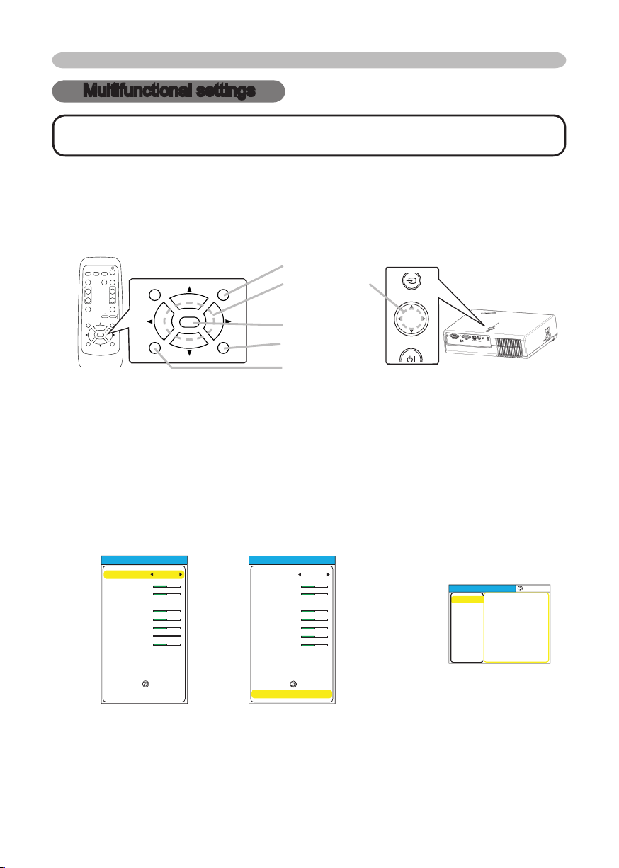
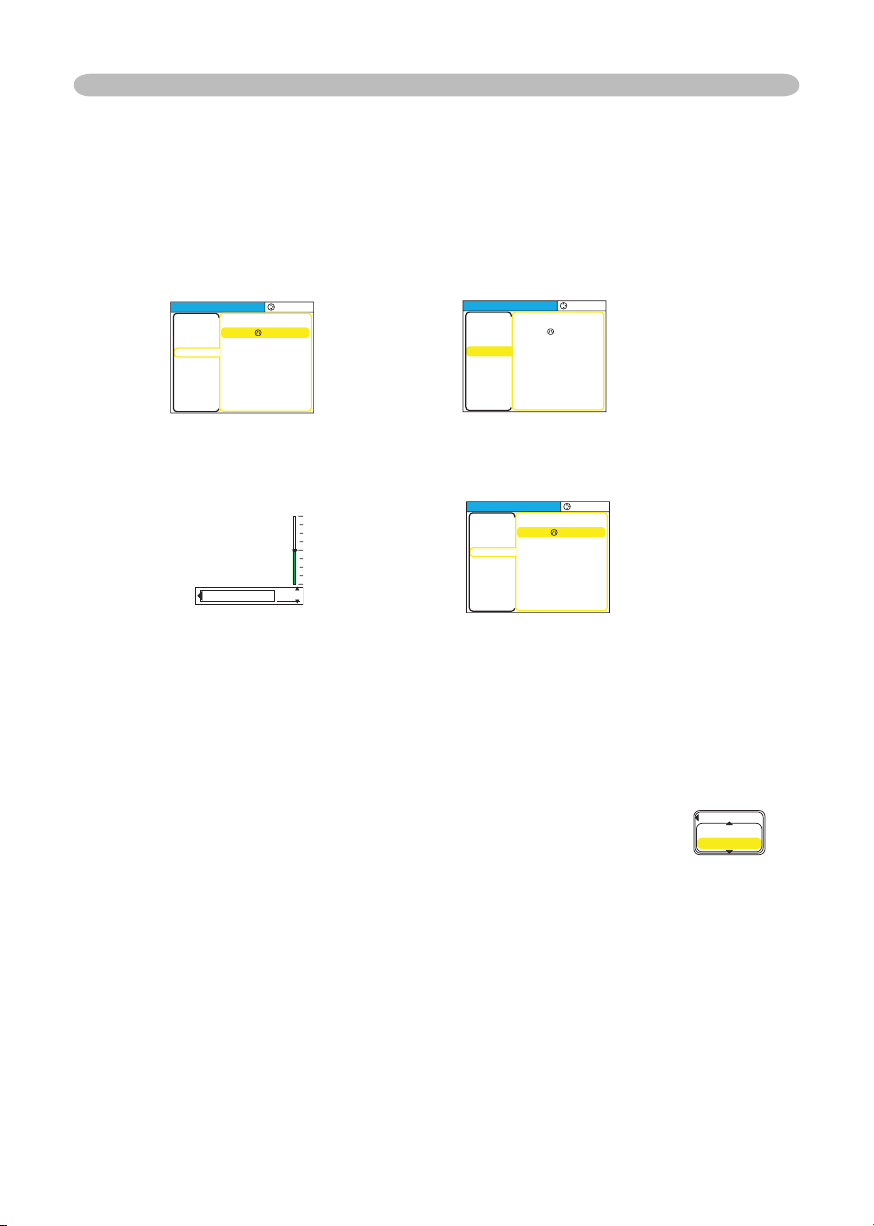
1.
To display a menu
Press the MENU button on the remote control or one of the cursor buttons
▲/▼/◄/► on the projector. The Advanced MENU or EASY MENU will appear.
2.
To choose the target menu
Point at one of choices on the menu using the cursor buttons ▲/▼, then
press the cursor button ► or the ENTER button.
At the Advance menu, when some menu is chosen already and you want to
choose other menu, please return to the main menu beforehand, using the
cursor button ◄ or the ESC button before choosing the menu.
(1) EASY MENU → Advance MENU (Main)
Multifunctional settings
Multifunctional settings
NOTE • Regardless of description of this manual, these functions may not work
correctly with some input.
Using the menu function
This projector has the following menus: PICTURE, IMAGE, INPUT, SETUP,
SCREEN, OPTION and EASY MENU. Each of these menus is operated using the
same methods. The basic operations of these menus are as follows.
► /
ENTER
Advanced MENU
MENU
[
RGB
]
:SELECT
PICTURE
IMAGE
INPUT
SETUP
SCREEN
OPTION
EASY MEN
U
BRIGHT
CONTRAS
T
GAMMA
COLOR TEMP
COLOR
TINT
SHARPNES
S
PROGRESSIVE
MY MEMOR
Y
+0
+0
DEFAULT
1
HIG
H
+0
+0
+0
TURN OFF
SAVE
1
▼
EASY MENU
EASY MENU
ASPECT
ZOOM
KEYST
ONE
MODE
BRIGHT
CONTRAS
T
COLO
R
TINT
SHRPNESS
WHISPER
MIRROR
RESE
T
FILTER TIME
LANGUAGE
4:3
+0
+0
NORMAL
+0
+0
+0
+0
+3
NORMAL
NORMAL
0
ENGLISH
Go To Advance Menu...
EASY MENU
EASY MENU
ASPECT
ZOOM
KEYST
ONE
MODE
BRIGHT
CONTRAS
T
COLO
R
TINT
SHRPNESS
WHISPER
MIRROR
RESE
T
FILTER TIME
LANGUAGE
4:3
+0
+0
NORMAL
+0
+0
+0
+0
+3
NORMAL
NORMAL
0
ENGLISH
Go To Advance Menu...
VIDEO
RG
B
SEARC
H
FREEZE
OFF
ON
MAGNIFY
ASPECT AUTO
BLAN
K
MUTE
VOLUME
KEYSTONE
POSITION
ES
C
ENTE
R
MENU
RESE
T
ZOOM
+
-
VIDEO
RG
B
SEARC
H
FREEZE
OFF
ON
MAGNIFY
ASPECT AUTO
BLAN
K
MUTE
VOLUME
KEYSTONE
POSITION
ES
C
ENTE
R
MENU
RESE
T
ZOOM
+
-
RESET button
ENTER button
MENU button
Cursor buttons
▲/▼/◄/►
ESC button
STAND B Y/ON
IN PU
T
ME NU
LA MP
TEM P
POW E R
23
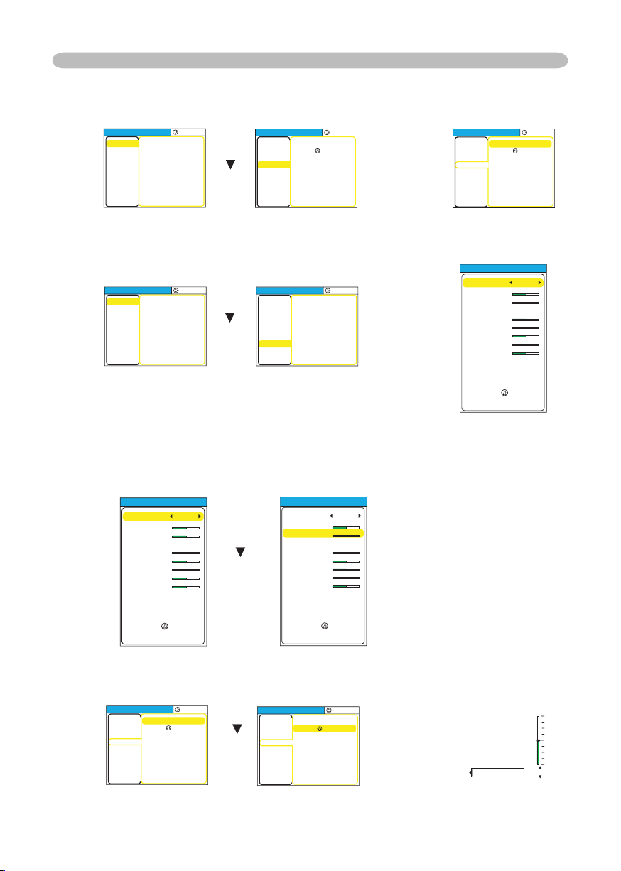
(2) Main of Advanced MENU Main → one of Advanced Menus (ex. SETUP
menu)
(3) Advanced Menu (Main) → EASY MENU
3.
To choose the target item
Point at one of choices on the menu using the cursor buttons ▲/▼. At an
Advanced menu, then press the cursor button ► or the ENTER button.
(1) At EASY MENU (ex. KEYSTONE)
(2) At Advanced Menu (ex. KEYSTONE)
Multifunctional settings
Main of Advanced
MENU
MENU
[
RGB
]
:SELECT
PICTURE
IMAGE
INPUT
SETUP
SCREEN
OPTION
EASY MEN
U
BRIGHT
CONTRAS
T
GAMMA
COLOR TEMP
COLOR
TINT
SHARPNES
S
PROGRESSIVE
MY MEMOR
Y
+0
+0
DEFAULT
1
HIG
H
+0
+0
+0
TURN OFF
SAVE
1
▼
MENU
[
RGB
]
:SELECT
PICTURE
IMAGE
INPUT
SETUP
SCREEN
OPTION
EASY MEN
U
ZOOM
KEYST
ONE
WHISPER
MIRROR
VOLUM
E
100
+0
NORMAL
NORMAL
16
Main of Advanced
MENU
► /
ENTER
MENU
[
RGB
]
:SELECT
ZOOM
KEYST
ONE
WHISPER
MIRROR
VOLUM
E
100
+0
NORMAL
NORMAL
16
PICTURE
IMAGE
INPUT
SETUP
SCREEN
OPTION
EASY MEN
U
SETUP menu of
Advanced MENU
Advanced Menu
(Main)
MENU
[
RGB
]
:SELECT
PICTURE
IMAGE
INPUT
SETUP
SCREEN
OPTION
EASY MEN
U
BRIGHT
CONTRAS
T
GAMMA
COLOR TEMP
COLOR
TINT
SHARPNES
S
PROGRESSIVE
MY MEMOR
Y
+0
+0
DEFAULT
1
HIG
H
+0
+0
+0
TURN OFF
SAVE
1
▼
► /
ENTER
MENU
[
RGB
]
:SELECT
PICTURE
IMAGE
INPUT
SETUP
SCREEN
OPTION
EASY MEN
U
Go To Easy Menu...
Advanced Menu
(Main)
EASY MENU
EASY MENU
ASPECT
ZOOM
KEYST
ONE
MODE
BRIGHT
CONTRAS
T
COLO
R
TINT
SHRPNESS
WHISPER
MIRROR
RESE
T
FILTER TIME
LANGUAGE
4:3
+0
+0
NORMAL
+0
+0
+0
+0
+3
NORMAL
NORMAL
0
ENGLISH
Go To Advance Menu...
ASPECT is chosen
EASY MENU
ASPECT
ZOOM
KEYST
ONE
MODE
BRIGHT
CONTRAS
T
COLO
R
TINT
SHRPNESS
WHISPER
MIRROR
RESE
T
FILTER TIME
LANGUAGE
4:3
+0
+0
NORMAL
+0
+0
+0
+0
+3
NORMAL
NORMAL
0
ENGLISH
Go To Advance Menu...
▼
▼
► /
ENTER
EASY MENU
ASPECT
ZOOM
KEYST
ONE
MODE
BRIGHT
CONTRAS
T
COLO
R
TINT
SHRPNESS
WHISPER
MIRROR
RESE
T
FILTER TIME
LANGUAGE
4:3
+0
+0
NORMAL
+0
+0
+0
+0
+3
NORMAL
NORMAL
0
ENGLISH
Go To Advance Menu...
KEYSTONE is chosen
MENU
[
RGB
]
:SELECT
ZOOM
KEYST
ONE
WHISPER
MIRROR
VOLUM
E
100
+0
NORMAL
NORMAL
16
PICTURE
IMAGE
INPUT
SETUP
SCREEN
OPTION
EASY MEN
U
MENU
[
RGB
]
:SELECT
ZOOM
KEYST
ONE
WHISPER
MIRROR
VOLUM
E
100
+0
NORMAL
NORMAL
16
PICTURE
IMAGE
INPUT
SETUP
SCREEN
OPTION
EASY MEN
U
KEYSTONE is chosen
KEYSTONE +0
24
4.
To operate
Please follow of the mention concerned in each. In general,
(1) At EASY MENU, use the cursor buttons ◄/► to operate.
(2) At Advanced MENU, use the cursor buttons ▲/▼.
5.
To return to the previous menu
Press the cursor button ◄ or the ESC button.
(1) One of Advanced Menus (ex. SETUP menu) → Main of Advanced MENU
(2) Dialogs for operation (ex. KEYSTONE) → Advanced MENU
6.
To reset
(1) Each item
Press the RESET button while operating.
(2) Items of EASY MENU (at a time)
Point at “RESET” on the menu using the cursor buttons ▲/▼, then press
the cursor button ► or the ENTER button. The dialog for reset will appear.
Point at “RESET” on the dialog using the cursor button ▲.
(3) Items of an Advanced MENU
Press the RESET button while pointing the menu name.
The dialog for reset will appear.
Point at “RESET” on the dialog using the cursor button ▲.
Note that items whose functions are performed simultaneously with operation
(ex. LANGUAGE, H PHASE etc.) aren’t reset.
7.
To close the menu
Press the MENU button again.
Even if you don't do anything, the operation will complete and the menu will
disappear automatically after about 10 seconds.
Multifunctional settings
MENU
[
RGB
]
:SELECT
PICTURE
IMAGE
INPUT
SETUP
SCREEN
OPTION
EASY MEN
U
ZOOM
KEYST
ONE
WHISPER
MIRROR
VOLUM
E
100
+0
NORMAL
NORMAL
16
Main of Advanced
MENU
MENU
[
RGB
]
:SELECT
ZOOM
KEYST
ONE
WHISPER
MIRROR
VOLUM
E
100
+0
NORMAL
NORMAL
16
PICTURE
IMAGE
INPUT
SETUP
SCREEN
OPTION
EASY MEN
U
SETUP MENU of
Advanced MENU
◄ /
ESC
MENU
[
RGB
]
:SELECT
ZOOM
KEYST
ONE
WHISPER
MIRROR
VOLUM
E
100
+0
NORMAL
NORMAL
16
PICTURE
IMAGE
INPUT
SETUP
SCREEN
OPTION
EASY MEN
U
SETUP menu
Dialog for KEYSTONE
◄ /
ESC
KEYSTONE +0
PICTURE
RESET
CANCEL
25
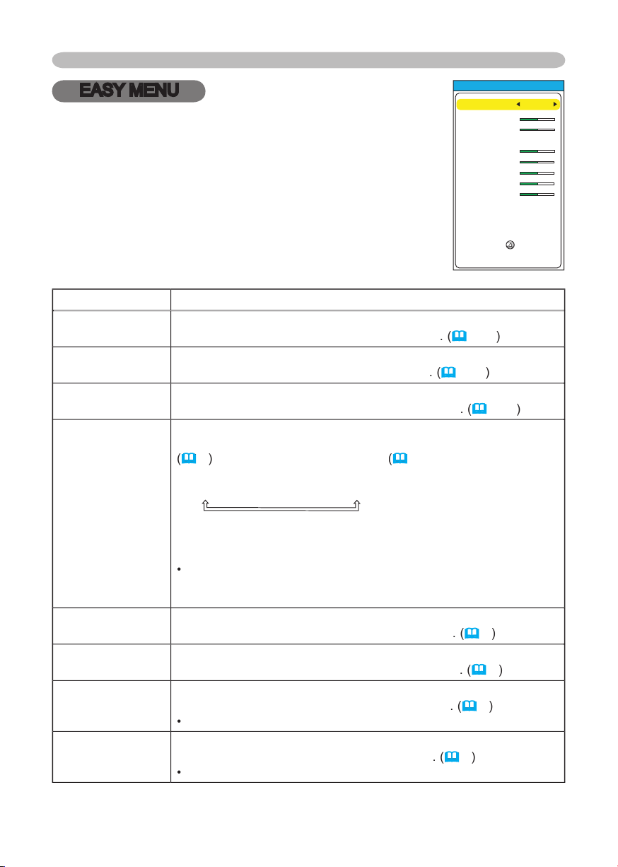
Multifunctional settings
EASY MENU
Item
Description
ASPECT
Using the buttons ◄/► switches the mode for aspect ratio.
See the item ASPECT of section IMAGE menu
.
(
30, 19
)
ZOOM
Using the buttons ◄/► adjusts the zoom.
See the item ZOOM of section SETUP menu
.
(
34, 19
)
KEYSTONE
Using the
buttons ◄/►
c
orrects the keystone distortion.
See the item
KEYSTONE
of section
SETUP
menu
.
(
34, 20
)
MODE
Using the buttons ◄/► switches the mode
of picture type. The
modes of picture type are combinations of a mode of GAMMA
(
2
7
)
and a mode of COLOR
TEMP
(
2
8
).
Choose a suitable
mode according to the projected source.
NORMAL
CINEMA
DYNAMIC
NORMAL: (COLOR TEMP = MIDDLE) + (GAMMA = #1 DEFAULT)
CINEMA: (COLOR TEMP = LOW) + (GAMMA = #2 DEFAULT)
DYNAMIC: (COLOR TEMP = HIGH) + (GAMMA = #3 DEFAULT)
•
When the combination of GAMMA and COLOR TEMP differs from
pre-assigned modes above, the display on the menu for the MODE
is “CUSTOM”.
BRIGHT
Using the buttons ◄/►
adjusts the brightness.
See the item
BRIGHT
of section
PICTURE
menu
.
(
2
7
)
CONTRAST
Using the buttons ◄/► adjusts the contrast.
See the item
CONTRAST
of section
PICTURE
menu
.
(
2
7
)
COLOR
Using the buttons ◄/► adjusts the strength of whole color.
See the item
COLOR
of section
PICTURE
menu
.
(
2
8
)
•
This item can be chosen only at a video signal.
TINT
Using the buttons ◄/► adjusts the tint.
See the item
TINT
of section
PICTURE
menu
.
(
2
8
)
•
This item can be chosen only at a video signal.
With the EASY MENU, items shown in the table below can
be performed.
Choose an item using the cursor buttons ▲/▼ on the
projector or remote control. Then perform it referring to the
following table.
EASY MENU
ASPECT
ZOOM
KEYST
ONE
MODE
BRIGHT
CONTRAS
T
COLO
R
TINT
SHRPNESS
WHISPER
MIRROR
RESE
T
FILTER TIME
LANGUAGE
4:3
+0
+0
NORMAL
+0
+0
+0
+0
+3
NORMAL
NORMAL
0
ENGLISH
Go To Advance Menu...
26
Multifunctional settings
Item
Description
SHARPNESS
Using the buttons ◄/► adjusts the sharpness.
See the item
SHARPNESS
of section
PICTURE
menu
.
(
28
)
WHISPER
Using the buttons ◄/► turns off/on the whisper mode.
See the item
WHISPER
of section
SETUP
menu
.
(
3
4
)
MIRROR
Using the buttons ◄/► switches the mode for mirror status.
See the item
MIRROR
of section
SETUP
menu
.
(
3
4
)
RESET
Performing this item resets all of the items of EASY MENU except
FILTER TIME and LANGUAGE.
Pressing the button ► displays a dialog to make sure. To perform
reset, point at RESET using the button ▲.
(
2
4
)
FILTER TIME
Performing this item resets the fi lter timer which counts use time of
air fi lter.
See the item
FILTER TIME
of section
OPTION
menu
.
(
3
9
)
LANGUAGE
Using the buttons ◄/► switches the language of menu.
See the item LANGUAGE of section SCREEN menu.
(
3
5
)
Go To
Advanced Menu
Pointing at the “Go To Advanced Menu” and pressing the button ►
changes the EASY MENU into the Advanced MENU.
(
22
)
Performs to use the menu of PICTURE, IMAGE, INPUT, SETUP,
SCREEN or OPTION.
EASY MENU (continued)
27
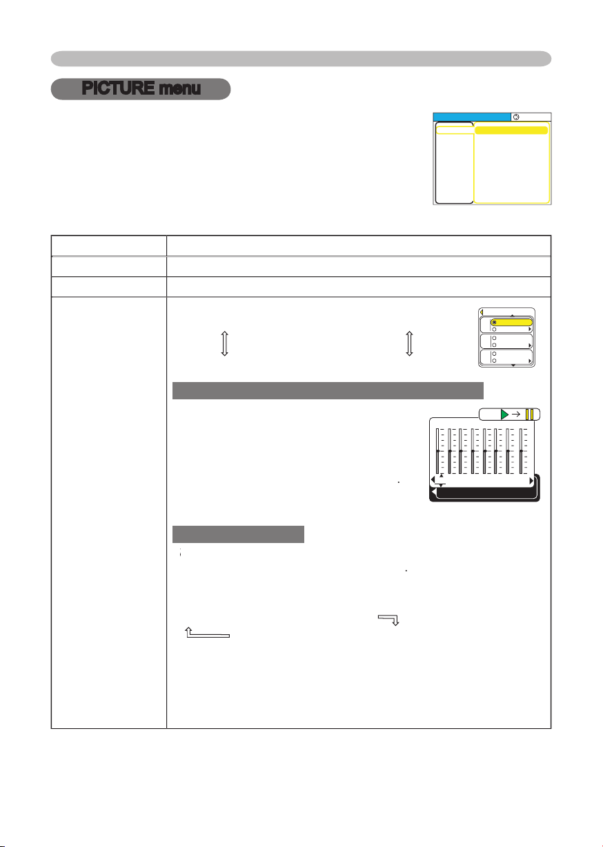
Multifunctional settings
PICTURE menu
Item
Description
BRIGHT
Using the buttons ▲/▼ adjusts the brightness.
: Light
Dark
CONTRAST
Using the buttons ▲/▼ adjusts the contrast.
:
Strong
Weak
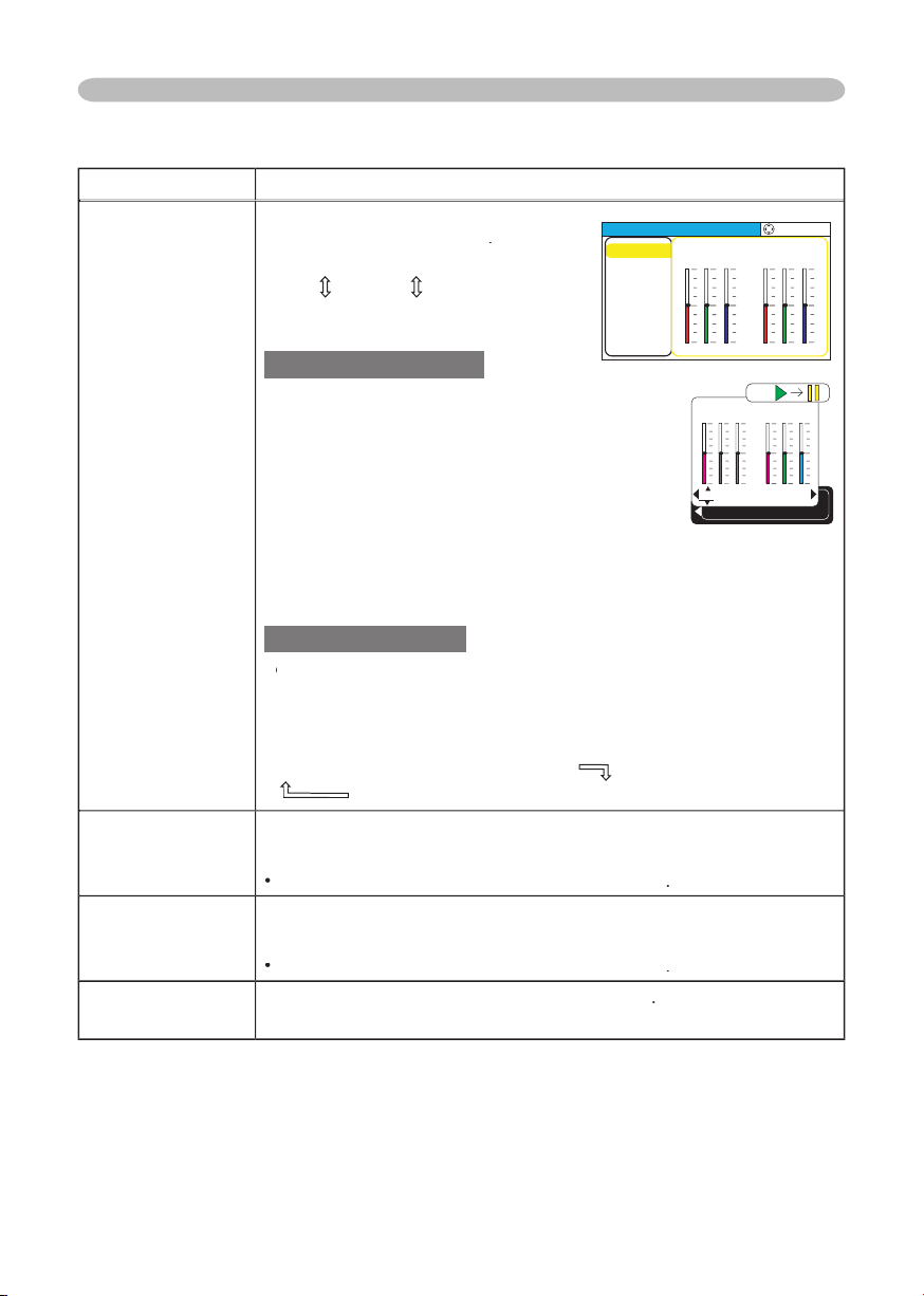
GAMMA
Using the buttons ▲/▼ switches the
GAMMA mode.
#1 DEFAULT
#1 CUSTOM
#2 DEFAULT
#3 CUSTOM
#3 DEFAULT
#
2
CUSTOM
To adjust #1 CUSTOM, #2 CUSTOM or #3 CUSTOM
Selecting
a mode of CUSTOM
and then
pressing the button ►
or the ENTER button
displays a dialog to aid you in adjusting the
mode.
This function is useful when you want to
change the brightness of particular tones
.
Choose
an item
using the buttons ◄/►, and
adjust the level using the buttons ▲/▼.
Using a test pattern
Y
ou can display a test pattern for checking the effect of your
You can display a test pattern for checking the effect of your Y
adjustment by pressing the ENTER button
.
Each time you press the ENTER button, the pattern changes as
below.
No pattern
Gray scale of 9 steps
Ramp
Gray scale of 15 steps
Eight of equalizing bars corresponds to eight of tone level of test
pattern except the darkest in the left end. If you want to adjust
the 2nd tone from left end on the test pattern, use the equalizing
adjustment bar “1”. The darkest tone at the left end of the test
pattern cannot be controlled with any of equalizing adjustment bar.
With the PICTURE menu, items shown in the table below
can be performed.
Choose an item using the cursor buttons ▲/▼ on the
projector or remote control, and press the cursor button ►
on the projector or remote control, or the ENTER button on
the remote control to progress. Then perform it referring to
the following table.
MENU
[
RGB
]
:SELECT
PICTURE
IMAGE
INPUT
SETUP
SCREEN
OPTION
EASY MEN
U
BRIGHT
CONTRAS
T
GAMMA
COLOR TEMP
COLOR
TINT
SHARPNES
S
PROGRESSIVE
MY MEMOR
Y
+0
+0
DEFAULT
1
HIG
H
+0
+0
+0
TURN OFF
SAVE
1
1
+0
2
+0
3
+0
4
+0
5
+0
6
+0
7
+0
8
+0
GAMMA
[
CUSTOM 1
]
ENTER :
Ramp
DEFAULT
CUSTO
M
DEFAULT
CUSTO
M
GAMMA
DEFAULT
CUSTO
M
#1
#2
#3
28
Multifunctional settings
Item
Description
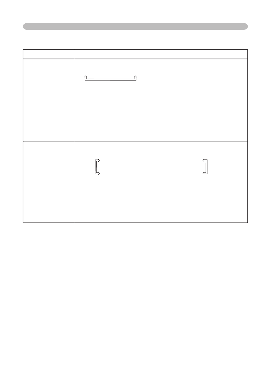
COLOR TEMP
Using the buttons ▲/▼ switches
the
mode of color temperature
.
HIGH
MIDDLE
CUSTOM
LOW
To adjust CUSTOM
Selecting
the
CUSTOM and then pressing the
button ► or the ENTER butto
n
dis
plays
a
dialog
to aid you in adjusting the OFFSET and/or GAIN
of CUSTOM mode.
OFFSET adjustments change the color intensity
on the whole tones of the test pattern.
GAIN adjustments mainly affect color intensity
on the brighter tones of the test pattern.
Choose an item using the buttons ◄/►, and adjust the level using
the buttons ▲/▼.
Using a test pattern
Y
ou can display a test pattern for checking the effect of your
You can display a test pattern for checking the effect of your Y
adjustment by pressing the ENTER button.
Each time you press the ENTER button, the pattern changes as
below.
No pattern
Gray scale of 9 steps
Ramp
Gray scale of 15 steps
COLOR
Using the buttons ▲/▼ adjusts the
strength of whole color.
Strong
Weak
•
This item can be chosen only at a vid
eo signal
.
TINT
Using the buttons ▲/▼ adjusts the
tint.
Green
Red
•
This item can be chosen only at a vid
eo signal
.
SHARPNESS
Using the buttons ▲/▼ adjusts th
e
sharpness
.
Strong
Weak
PICTURE menu (continued)
R
+0
G
+0
B
+0
COLOR TEMP
ENTER :
OFFSET
R
+0
G
+0
B
+0
GAIN
Ramp
:SELECT
HIGH
MIDDLE
LOW
CUSTOM
COLOR TEMP
[
RGB
]
R
+0
G
+0
B
+0
OFFSET
R
+0
G
+0
B
+0
GAIN
29
Multifunctional settings
Item
Description
PROGRESSIVE
Using the buttons ▲/▼ switches the
progressive mode.
TV
FILM
TURN OFF
• This function performs only at an interlaced signal of a VIDEO
input, a S-VIDEO input or a component video input of 525i (480i) or
625i (576i) signal.
•
When the TV or FILM is selected, the screen image will be crisper.
The FILM mode is adaptable to the 2-3 Pull-Down system to the
conversion.
(not adaptable to the 2-2 Pull-Down system)
Bu
t these
may cause a certain defect (for example, jagged line) of the picture
at a quick moving object. In such a case, please select the TURN
OFF, even though the screen image may lose the crisp.
MY MEMORY
Choosing a mode of MY MEMORY using the buttons ▲/▼ and then
pressing the button ► or the ENTER button performs each function.
LOAD1
LOAD2
LOAD3
LOAD4
SAVE4
SAVE3
SAVE2
SAVE1
This projector has 4 numbered memories for adjustment data.
Performing the LOAD1, LOAD2, LOAD3 or LOAD4 loads the data on
the memory whose number corresponds with the command’s number,
and adjusts the picture automatically depending on the data.
Performing the SAVE1, SAVE2, SAVE3 or SAVE4 puts the current
adjustment data on the memory whose number corresponds with
the command’s number.
PICTURE menu (continued)
30
Multifunctional settings
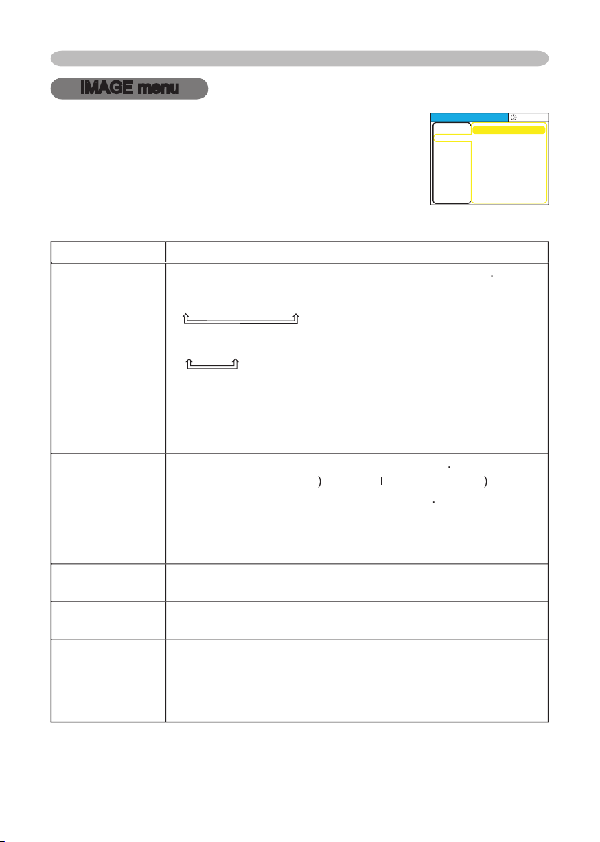
IMAGE menu
Item
Description
ASPECT
Using the buttons ▲/▼ switches the
mode for aspect ratio
.
At a
RGB signal
4:3
16:9
NORMAL
At a
video signal / no signal
4:3
16:9
•
The NORMAL mode keeps the original aspect ratio of the signal.
• At a HDTV component video signal of 1125i (1080i) or 750p (720p),
this item can’t be chosen.
•
Performing the automatic adjustment initializes the aspect ratio
setting.
OVER SCAN
Using the buttons ▲/▼ adjusts the
over-scan ratio
.
Large (
It reduces picture
)
Small (
I
t
magnifi es picture
)
•
This item can be chosen only at a video signal
.
•
When this adjustment is too large, certain degradation may appear
at the frame area of the picture. In such a case, please adjust small.
•
The number displayed on the menu during this adjustment is jest
for your reference, and might not be exact display ratio.
V POSITION
Using the buttons ▲/▼ adjusts the vertical position.
Up
Down
H POSITION
Using the buttons ▲/▼ adjusts the horizontal position.
Left
Right
H PHASE
Using the buttons ▲/▼ adjusts the horizontal phase to eliminate
fl icker.
Right
Left
• This item can be chosen only at a RGB signal or a component
video signal (except 525i (480i) and 625i (576i)).
With the IMAGE menu, items shown in the table below can
be performed.
Choose an item using the cursor buttons ▲/▼ on the
projector or remote control, and press the cursor button ►
on the projector or remote control, or the ENTER button on
the remote control to progress. Then perform it referring to
the following table.
MENU
[
RGB
]
:SELECT
PICTURE
IMAGE
INPUT
SETUP
SCREEN
OPTION
EASY MEN
U
ASPECT
OVER SCAN
V POSITION
H POSITION
H PHAS
E
H SIZE
AUTO ADJUST EXECUTE
4:3
95
25
142
16
1344

31
Multifunctional settings
Item
Description
H SIZE
Using the buttons ▲/▼ adjusts the horizontal size.
Large
Small
•
This item can be chosen only at a RGB signal.
• When this adjustment is excessive, the picture may not be
displayed correctly. In such a case, please reset the adjustment
pressing the RESET button during this operation.
AUTO ADJUST
EXECUTE
Choos
ing this item performs the automatic adjustment feature.
At a RGB signal
The vertical position, the horizontal position, the clock phase and
horizontal size will be automatically adjusted.And the aspect ratio
(ASPECT) will be automatically selected.
Make sure that the application window is set to its maximum size
prior to attempting to use this feature. A dark picture may still be
incorrectly adjusted. Use a bright picture when adjusting.
At a video signal or s-video signal
The signal type mode best suited for the respective input signal
and the aspect ratio (ASPECT) will be selected automatically.
And the vertical position (V POSITION), the horizontal position (H
POSITION) will be automatically adjusted.
At a component video signal
The vertical position (V POSITION), the horizontal position (H
POSITION) and the clock phase (H POSITION) will be automatically
adjusted. And the aspect ratio (ASPECT) will be automatically
selected.
•
This function is available only when the AUTO mode is selected to
the item VIDEO FORMAT of INPUT menu. For a component video
signal, the signal type is identifi ed automatically independently of
this function.
•
The automatic adjustment operation requires approximately 10
seconds. Also please note that it may not function correctly with
some input.
•
This operation may not work well at some signals. If the picture
becomes unstable (ex. a irregular picture, a color lack), please
select the suitable mode to the item “VIDEO” of the INPUT menu.
IMAGE menu (continued)
32
Multifunctional settings
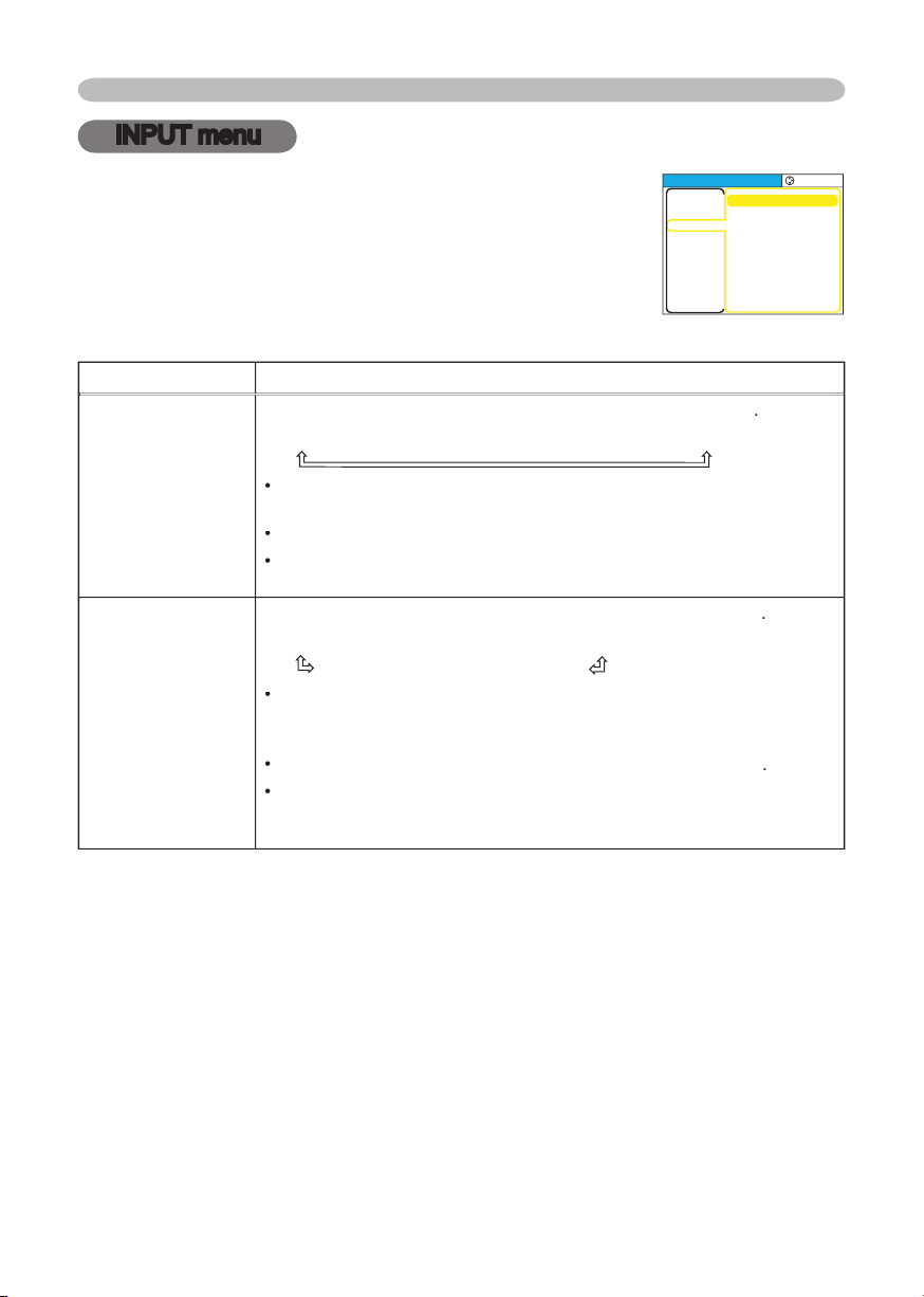
INPUT menu
Item
Description
COLOR SPACE
Using the buttons ▲/▼ switches the
mode for color spac
e
.
AUTO
RGB
SMPTE240
REC709
REC601
•
This item can be chosen only at a RGB signal or a component
video signal.
•
The AUTO mode automatically selects the optimum mode.
•
The AUTO operation may not work well at some signals.
In such a
case,
select a suitable mode except the AUTO.
VIDEO FORMAT
Using the buttons ▲/▼ switches the
mode for video forma
t
.
AUTO
NTSC
PAL
SECAM
N-PAL
M-PAL
NTSC4.43
•
This item performs only at a video signal from the VIDEO port or
the S-VIDEO port. For a component video signal, the signal type is
identifi ed automatically, independently of this function.
•
The AUTO mode automatically selects the optimum mode
.
•
The AUTO operation may not work well at some signals. If the
picture becomes unstable (ex. an irregular picture, a color lack),
please select the mode depending on the input signal.
With the INPUT menu, items shown in the table below can
be performed.
Choose an item using the cursor buttons ▲/▼ on the
projector or remote control, and press the cursor button ►
on the projector or remote control, or the ENTER button on
the remote control to progress. Then perform it referring to
the following table.
MENU
[
RGB
]
:SELECT
COLOR SPACE
VIDEO FORMA
T
FRAME LOCK
INFORMA
TION
AUT
O
AUT
O
TURN OFF
PICTURE
IMAGE
INPUT
SETUP
SCREEN
OPTION
EASY MEN
U
33
Multifunctional settings
INPUT menu (continued)
Item Description
FRAME LOCK
Using the buttons ▲/▼ turns the frame lock function on/off.
TURN ON
TURN OFF
• This item performs only at a RGB signal with vertical frequency of
50 to 60 Hz.
• When the TURN ON is selected, a moving picture is displayed
more smoothly.
• This function may cause a certain degradation of the picture. In
such a case, please select the TURN OFF.
INFORMATION
Choosing this item displays a dialog titled “INPUT INFORMATION”.
It shows the information about the current input.
• The “FRAME LOCK” message on the dialog means the frame lock
function is working.
(
33)
• This item can't be chosen at no signal.
INPUT-INFORMATION
RGB
1024x768 @60.0
FRAME LOCK
INPUT-INFORMATION
S-VIDEO
SECAM
AUTO
34
Multifunctional settings
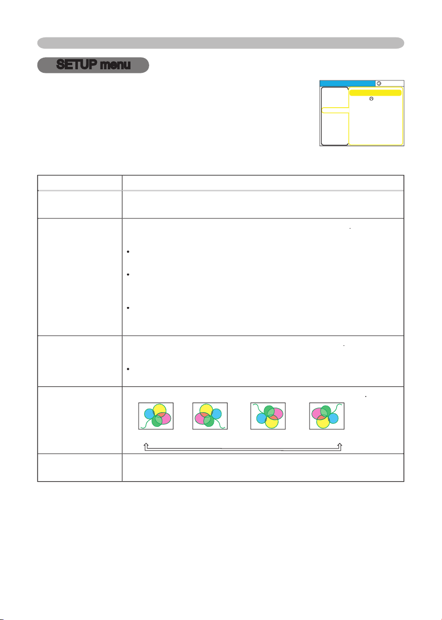
SETUP menu
Item
Description
ZOOM
Using the buttons ▲/▼ adjusts the zoom (magnifying power).
Larg
e
S
mall
KEYSTONE
Using the buttons ▲/▼
corrects the keystone distortion
.
Upper in the data
Lower in the data
•
The adjustable range of this function will vary with the type of input
signal. At some signals, this function may not work well.
•
When the V:INVERT or the H&V:INVERT is selected under the
item MIRROR, if the projector screen is inclined or if the projector is
angled downward, this function may not work correctly.
•
When the zoom adjustment is set to the TELE side, this correction
may be excessive. This function should be used with zoom set to
WIDE whenever possible.
WHISPER
Using the buttons ▲/▼
turns off/on the whisper mode
.
NORMAL
WHISPER
•
When the WHISPER is selected, acoustic noise and screen
brightness are reduced.
MIRROR
Using the buttons ▲/▼ switches the
mode for mirror status
.
NORMAL
H:INVERT
V:INVERT
H&V:INVERT
VOLUME
Using the buttons ▲/▼ adjusts the volume.
High
Low
With the SETUP menu, items shown in the table below can
be performed.
Choose an item using the cursor buttons ▲/▼ on the
projector or remote control, and press the cursor button ►
on the projector or remote control, or the ENTER button on
the remote control to progress. Then perform it referring to
the following table.
MENU
[
RGB
]
:SELECT
ZOOM
KEYST
ONE
WHISPER
MIRROR
VOLUM
E
100
+0
NORMAL
NORMAL
16
PICTURE
IMAGE
INPUT
SETUP
SCREEN
OPTION
EASY MEN
U
35
Multifunctional settings
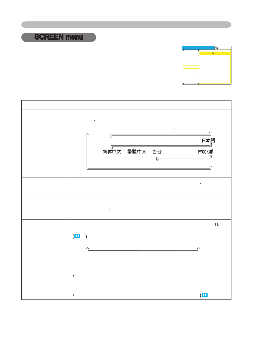
SCREEN menu
Item
Description
LANGUAGE
Using the buttons ▲/▼ switches the
OSD (On Screen Display)
language
.
SUOMI
POLSKI
TÜRKÇE
ENGLISH
FRANÇAIS
DEUTSCH
ESP
AÑOL
ESPAÑOL ESP
I
TA
LIAN
O
NORSK
NEDERLANDS
POR
TUGUÊS
SVENSKA
TÜRKÇE
MENU POSITION
Using the buttons ◄/►/▲/▼ adjusts the
menu position
.
To quit the operation, press the MENU button or keep no operation
for 10 seconds.
OSD BRIGHT
Using the buttons ▲/▼ switches the
brightness level of the OSD (On
Screen Display)
.
Bright
Dark
BLANK
Using the buttons ▲/▼ switches the
mode for the blank scree
n
.
The blank screen is the screen
for the temporarily blanking feature
(
2
1
)
.
It is displayed by pressing the BLANK button.
MyScreen
ORIGINAL
BLUE
WHITE
BLACK
MyScreen is the screen you can register a desired screen.
ORIGINAL screen is the existing standard screen.
BLUE, WHITE
and BLACK are non-patterned (plain) screens in each color.
•
To avoid remaining as an afterimage, the MyScreen and the
ORIGINAL screens will change to the BLACK screen after several
minutes.
•
For the MyScreen, please refer to the item MyScreen
(
3
6
).
With the SCREEN menu, items shown in the table below can
be performed.
Choose an item using the cursor buttons ▲/▼ on the
projector or remote control, and press the cursor button ►
on the projector or remote control, or the ENTER button on
the remote control to progress. Then perform it referring to
the following table.
MENU
[
RGB
]
:SELECT
LANGUAGE
MENU POSITION
OSD BRIGHT
BLANK
START UP
MyScreen
MyScreen Lock
MESSAGE
ENGLISH
5
BLACK
ORIGINA
L
TURN OFF
TURN ON
PICTURE
IMAGE
INPUT
SETUP
SCREEN
OPTION
EASY MEN
U
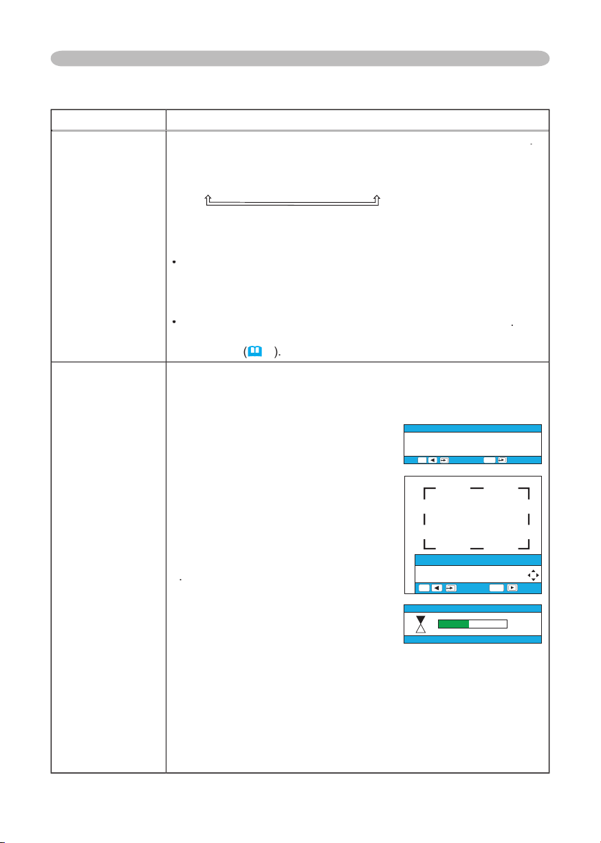
36
Multifunctional settings
Item
Description
START UP
Using the buttons ▲/▼ switches the
mode for the start up screen
.
The start up screen is the screen displayed when no signal or an
unsuitable signal is detected.
MyScreen
ORIGINAL
TURN OFF
MyScreen is the screen you can register a desired screen.
ORIGINAL screen is the existing standard screen. When the TURN
OFF is selected, the BLUE screen is used.
•
To avoid remaining as an afterimage, the MyScreen and the
ORIGINAL screens will change to the BLANK screen after several
minutes. If also the BLANK screen is the MyScreen or ORIGINAL, it
will change to the BLACK screen.
•
For the MyScreen, please refer to the item MyScreen
below
.
About the BLUE, BLACK and BLANK screens, please refer to the
item BLANK
(
3
5
)
.
MyScreen
This item functions for capturing the MyScreen of the blank screen
and the start up screen. Please execute displaying the input
including the picture you want to capture.
1. Choosing this item displays a dialog
titled “MyScreen”. It will ask you if
you start capturing the picture from
the current screen. Please wait for
the target picture to be displayed.
2. Press the ENTER button when the
picture is display. The picture will
freeze and the frame for capturing
appears.
To stop performing, press the
RESET or ESC button.
3
.
Using the buttons ◄/►/▲/▼ adjust
the frame position. Please move the
frame to the position of the picture
which you want to use.
To start registration, press the
ENTER button.
To restore the screen and return
to the previous dialog, press the
RESET or ESC button.
Registration takes
several
minutes. When the registration is
completed, the registered screen and the message “MyScreen
registration is fi nished.” are displayed for several seconds. If the
registration failed, the message “A capturing error has occurred.
Please try again.” is displayed.
SCREEN menu (continued)
MyScreen
Do you start capturing this picture?
, + :NO
ESC
, :YES
ENTER
MyScreen
Move the capture area
as you want.
, + :RETURN
ESC
, :NEXT
ENTER
My Screen
45%

37
Multifunctional settings
Item
Description
MyScreen Lock
Using the buttons ▲/▼
tu
rns on/off the MyScreen lock function
.
TURN ON
TURN OFF
When the TURN ON is selected, the item MyScreen cannot be
performed. Use this function for protecting the current MyScreen.
MESSAGE
Using the buttons ▲/▼
t
urns on/off the message function
.
TURN ON
TURN OFF
When the TURN ON is selected, the following message function
works.
“AUTO IN PROGRESS” while automatically adjusting
”NO INPUT IS DETECTED”
”SYNC IS OUT OF RANGE”
”
Searching ....
”
while searching for an input signal
”Detecting….” when an input signal is detected
The indication of the input signal by changing
The indication of the aspect ration by changing
SCREEN menu (continued)
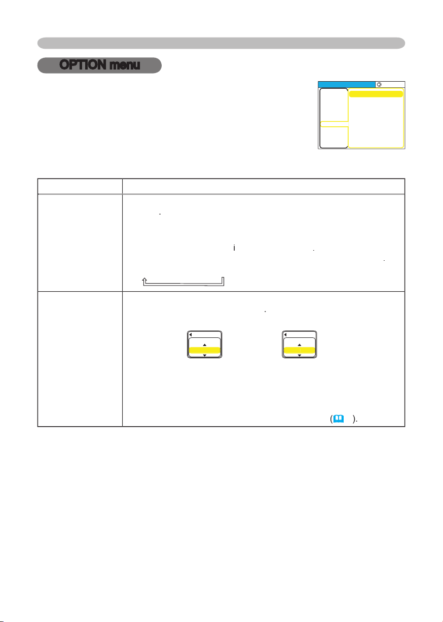
38
Multifunctional settings
OPTION menu
Item
Description
AUTO SEARCH
Using the buttons ▲/▼
turns on/off the automatic signal search
function
.
TURN ON
TURN OFF
When the TURN ON is selected, detecting no signal automatically
cycles through input ports
i
n order of followin
g
.
Then
when an input
is found, the proje
ctor will stop searching and display the image
.
RGB
S-VIDEO
VIDEO
AUTO OFF
Using the buttons ▲/▼ adjusts the
time to count down to
automatically turn the projector off
.
Long (max. 99 minutes)
Short (min. 0 minute = DISABLE)
AUT
O OF
F
ENABL
E
10
AUT
O OF
F
DISABLE
0
When the time is set to 0, the projector is not turned off
automatically.
When the time is set to 1 to 99, and when the passed time with
a no-signal or an unsuitable signal reaches at the set time, the
projector lamp will go off and the power indicator begins blinking.
Please refer to the section
“Turning off the power”
(
1
7
)
.
With the OPTION menu, items shown in the table below can
be performed.
Choose an item using the cursor buttons ▲/▼ on the
projector or remote control, and press the cursor button ►
on the projector or remote control, or the ENTER button on
the remote control to progress
, except for the items LAMP
TIME and FILTER TIME.
Then perform it referring to the
following table.
MENU
[
RGB
]
:SELECT
AUTO SEARCH
AUT
O OFF
LAMP TIME
FILTER TIME
SERVICE
TURN OFF
0
0
0
PICTURE
IMAGE
INPUT
SETUP
SCREEN
OPTION
EASY MEN
U
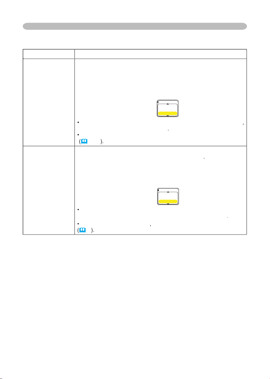
39
Multifunctional settings
Item
Description
LAMP TIME
The lamp time is the time counted after the last resetting. It is
shown
in the OPTION menu as the use time of the lamp.
Performing this
item resets the time.
Pressing the RESET button on the remote control or the button ►
on the projector for about 3 seconds displays a dialog to make sure.
To perform reset, point at RESET using the button ▲.
RESET
CANCEL
•
Please re
set the lamp time
only when you have replaced the lamp
,
for correct messages about the lamp
.
•
About the lamp
replacement
, please see the section "Lamp"
(
41, 42
)
.
FILTER TIME
The
fi lter time
is the time counted after the last resetting. It is shown
in the OPTION menu as the use time of the
air fi lter
.
Performing this
item resets the time.
Pressing the RESET button on the remote control or the button ►
on the projector for about 3 seconds displays a dialog to make sure.
To perform reset, point at RESET using the button ▲.
RESET
CANCEL
•
Please reset the fi lter time only when you have
cleaned or
replaced the
air fi lter
, for correct messages about the
air fi lter
.
•
About the
caring the air fi lter
,
ple
ase see the section "
Air fi lter
"
(
4
3
)
.
OPTION menu (continued)
LAMP TIME
0
RESET
CANCEL
FILTER TIME
0
RESET
CANCEL
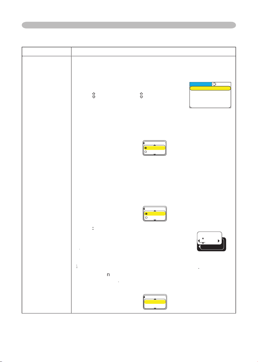
40
Multifunctional settings
Item
Description
SERVICE
Choosing this item displays the SERVICE menu.
Choose an item using the buttons ▲/▼, and press the button ► or
the ENTER button to progress.
FAN SPEED
AUTO ADJUST
FACTORY RES
ET
GHOST
FAN SPEED:
Using the buttons ▲/▼ switches the
r
otation speed of the cooling
fans. The HIGH is the mode for use at highlands etc.
Note that the
projector is noisier when the HIGH is selected.
HIGH
NORMAL
AUTO ADJUST:
Using the buttons ▲/▼ enables or disables the automatic
adjustment.
Depending on conditions, such as input image, signal cable to the
unit, environment around the unit, etc., the automatic adjustment
may not work correctly. In such a case, please choose DISABLE to
disable the automatic adjustment, and adjust manually.
ENABLE
DISABLE
GHOST
:
1.
Choose a color element of ghost using the
buttons ◄/►.
2.
Adjust the chosen element using the buttons
2. Adjust the chosen element using the buttons 2.
▲/▼ to disappear ghost.
FACTORY RESET:
T
o perform reset, point at RESET using the button ▲
To perform reset, point at RESET using the button ▲T
.
By this
functio
n
, all the items in all of menu will collectively return
to the
initial setting
.
N
ote
that the items LAMP TIME, FILTER TIME
and LANGUAGE are not reset.
RESET
CANCEL
OPTION menu (continued)
:SELECT
AUTO ADJUST
GHOST
FACTORY RESET
SERVICE
FANSPEED NORMAL
FANSPEED
HIGH
NORMAL
AUTO ADJUST
ENABLE
DISABLE
FACTORY RESET
RESET
CANCE
L
+0 +0
GHOST
+0
R G
B
41
Maintenance
Maintenance
Lamp
WARNING
HIGH VOLTAGE
HIGH TEMPERATURE
HIGH PRESSURE
►
The projector uses a high-pressure mercury glass lamp. The lamp can
break
with a loud bang, or burn out
with a loud bang, or burn out
, if jolted or scratched, handled while hot, or worn
over time. Note that each lamp has a different lifetime, and some may burst or
burn out soon after you start using them. In addition, when the bulb bursts, it is
possible for
shards of glass
shards of glass
to fl y into the lamp housing, and for
gas containing
gas containing
mercury
mercury
to escape from the projector’s vent holes.
►
About disposal of a lamp
• This product contains a mercury lamp; do not
put in trash. Dispose of in accord with environmental laws.
For lamp recycling, go to www.lamprecycle.org. (in the US)
For product disposal, contact your local government agency or www.eiae.org (in
the US) or www.epsc.ca (in Canada).
For more information, call your dealer.
•
If the lamp should break (it will make a loud bang when it does),
unplug the power cord from the outlet, and make sure to request a
replacement lamp from your local dealer. Note that shards of glass
could damage the projector’s internals, or cause injury during handling,
so please do not try to clean the projector or replace the lamp yourself.
• If the lamp should break (it will make a loud bang when it does),
ventilate the room well, and make sure not to breathe the gas that
comes out of the projector vents, or get it in your eyes or mouth.
• Before replacing the lamp, turn the projector off and unplug the power
cord, then wait at least 45 minutes for the lamp to cool sufficiently.
Handling the lamp while hot can cause burns, as well as damaging the
lamp.
•
Never unscrew except the appointed (marked by an arrow) screws.
• Do not open the lamp cover while the projector is suspended from
above. This is dangerous, since if the lamp’s bulb has broken, the
shards will fall out when the cover is opened. In addition, working in
high places is dangerous, so ask your local dealer to have the lamp
replaced even if the bulb is not broken.
• Do not use the projector with the lamp cover removed. At the lamp
replacing, make sure that the screws are screwed in firmly. Loose
screws could result in damage or injury.
•
Use only the lamp of the specifi ed type.
• If the lamp breaks soon after the first time it is used, it is possible
that there are electrical problems elsewhere besides the lamp. If this
happens, contact your local dealer or a service representative.
•
Handle with care: jolting or scratching could cause the lamp bulb to burst during use.
• If the indicators or a message prompts you to replace the lamp (see
the section "Related Messages" and "Regarding the indicator Lamps"),
replace the lamp as soon as possible. Using the lamp for long periods
of time, or past the replacement date, could cause it to burst. Do not
use old (used) lamps; this is a cause of breakage.
Disconnect
the plug
from the
power
outlet
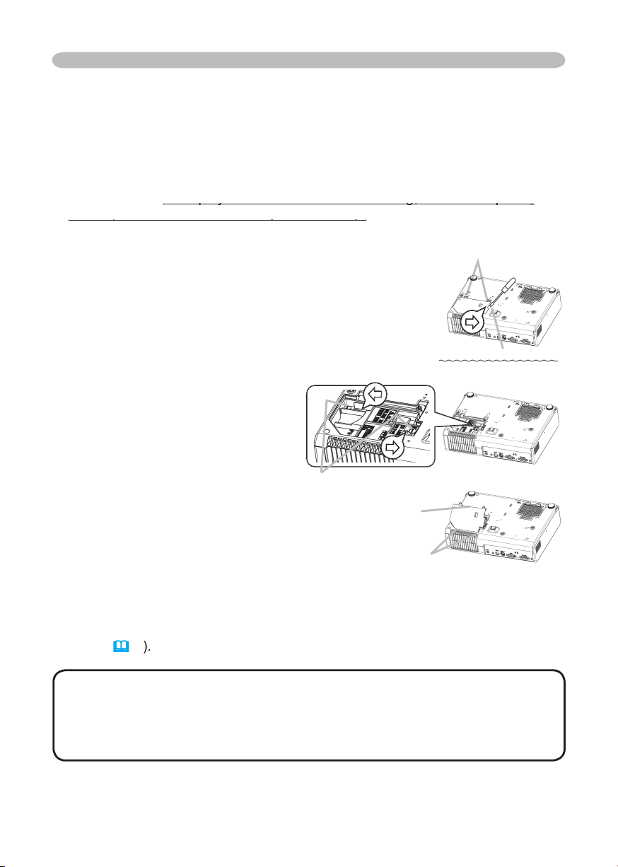
42
Lamp (continued)
When the indicators or a message prompts you to replace the lamp, replace the
lamp as soon as possible.
1.
Turn the projector off, and unplug the power cord. Allow the lamp to cool for
at least 45 minutes.
2.
To prepare a new lamp, contact your dealer and tell the lamp type number
=
DT00701
.
If the projector is mounted on the ceiling, or if the lamp has
If the projector is mounted on the ceiling, or if the lamp has
broken, also ask the dealer to replace the lamp.
broken, also ask the dealer to replace the lamp.
In the case of replacement by yourself,
3.
After making sure that the projector has cooled
adequately, slowly turn over the projector, so
that the bottom is facing up.
4.
Please loosen the screw (marked by arrow). Then,
unhook the claws of the lamp cover and remove the
lamp cover.
5.
Loosen the 2 screws (marked by arrow) of the lamp,
and slowly pick up the lamp by the
handles.
6.
Insert the new lamp, and retighten
fi rmly two screws that are loosened
in the previous process to lock it in
place.
7.
Interlocking the 2 tabs of the lamp
cover to the projector, position the
lamp cover on the project
or, and push the
center point of two claws to fi x the lamp cover.
Then retighten fi rmly the screw of the lamp
cover.
8.
Slowly turn the projector so that the top is
facing up.
9.
Turn the projector on, and reset the lamp time
using the LAMP TIME function of OPTION
menu
(
3
9
)
.
NOTE
• When the lamp has been replaced after the message of "THE
POWER WILL TURN OFF AFTER 0hr." is displayed, complete the following
operation within 10 minutes of switching power on.
• Incorrectly resetting of the lamp timer (resetting without replacement, or
neglect of resetting after replacement) will result in incorrect message functions.
Maintenance
Tabs
Screws marked
by arrow
Center
point
of claws
Claws of lamp cover
Screw marked by arrow
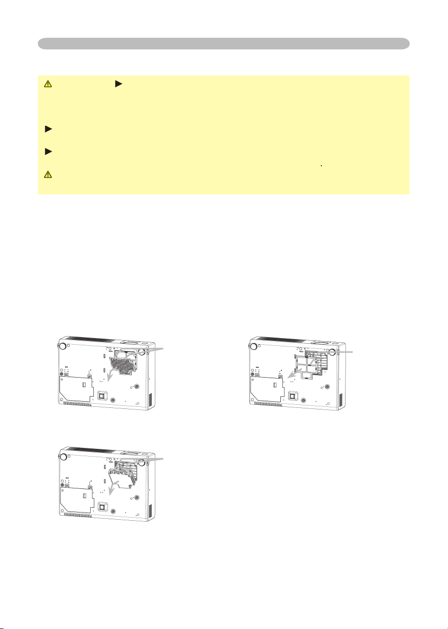
43
Maintenance
When the indicators or a message prompts you to clean the air fi lter, clean the
air fi lter as soon as possible. If the air fi lter becomes clogged by dust or the like,
internal temperatures rise and the power may be automatically turned off for
malfunction prevention.
1.
Disconnect all the connectors and adapters that were connected to the
projector’s ports. Then slowly turn the projector so that the lens-side is facing
up. Please be careful for a projector not to fall. While the projector is placed
lens-side up, hold the projector.
2.
Remove the fi lter cover and the air fi lter. Hold the knobs while pulling out it.
3.
Apply a vacuum cleaner to the vent of the projector for the air fi lter. And then
slowly turn the projector bottom up.
Usual fi lter cover
Filter cover’s
knobs
Filter cover’s
knobs
Air fi lter’s
knob
WARNING
►
Do not replace the air fi lter during use or immediately after use.
Handling while the projector is in a high temperature could cause a burn and/or
malfunction to the projector. Before operating, make sure that the power switch is
off, that the power cord is not plugged in, and that the projector is cool adequately.
►
Use only the air fi lter of the specifi ed type. Do not use the projector with the
air fi lter and fi lter cover removed.
►
Avoid wetting the projector or inserting liquids in the projector. It could result
in a fi re, an electric shock, and/or malfunction to the projector
.
CAUTION
►Please replace the air fi lter when it is damaged or too soiled,
and also when you replace the lamp.
Air fi lter
Filter cover for bottom-up use
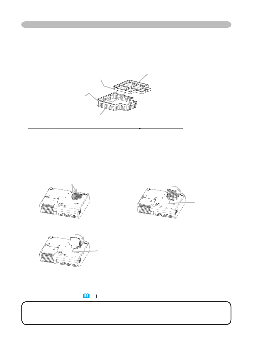
44
Maintenance
Air fi lter (continued)
4.
Apply a vacuum cleaner to the air fi lter and fi lter cover.
Then set a new or cleaned air fi lter into place.
In case of the fi lter cover for bottom-up use, remove the air fi lter from the fi lter
cover and clean each. After cleaning, reattach the cleaned fi lter to the fi lter cover.
Please replace the air fi lter when it is damaged or too soiled.
Please replace the air fi lter when it is damaged or too soiled.
To prepare a new air fi lter, contact your dealer and tell the air fi lter type number
=
NJ20922.
An air fi lter of specifi ed type will come even with the replacement lamp for this
projector.
5.
Position the air fi lter and fi lter cover into place.
6.
Slowly turn the projector so that the top is facing up, except for the case of
bottom-up use.
7.
Turn the projector on, and reset the fi lter time using the FILTER TIME function
of OPTION menu. (
3
9
)
NOTE
• Incorrectly resetting of the fi lter timer (resetting without replacement,
or neglect of resetting after replacement) will result in incorrect message
functions.
Claws
Air fi lter
Rail of air fi lter
Filter cover for bottom-up use
Usual fi lter cover
Push the points of “PUSH” word
with claws to fi x the air fi lter.
Interlocking the tabs,
snap the fi lter cover into place.
Filter cover for bottom-up use
Interlocking the tabs, snap the fi lter cover into place.
Tabs
Tabs

45
Maintenance
WARNING
►
Do not take care of the projector during use or immediately after
use. Handling while the projector is in a high temperature could cause a burn and/
or malfunction to the projector. Before operating, make sure that the power switch is
off, that the power cord is not plugged in, and that the projector is cool adequately.
►Never try to care for the inside of the projector personally. Doing is so
dangerous.
►Avoid wetting the projector or inserting liquids in the projector. It could result
in a fi re, an electric shock, and/or malfunction to the projector.
• Don’t put a container containing water, cleaner or chemicals near the
projector.
• Don’t use aerosols or sprays.
CAUTION
►Please take right care of the projector according to the
following. Incorrect care could cause not only an injury but adverse infl uence
such as discoloration, peeling paint, etc.
• Do not use cleaner or chemicals other than those listed below.
• Do not polish or wipe with hard objects.
Inside of the projector
In order to ensure the safe use of your projector, please have it cleaned and
inspected by your dealer about once every year.
Caring for the lens
If the lens is fl awed, soiled or fogged, it could cause deterioration of display
quality. Please take care of the lens, being cautious of the handling.
1.
Turn the projector off, and unplug the power cord. Allow the projector to cool
suffi ciently.
2.
After making sure that the projector is cool adequately, lightly wipe the lens
with a commercially available lens-cleaning wipe. Do not touch the lens
directly with your hand.
Caring for the cabinet and remote control
Incorrect care could have adverse infl uence such as discoloration, peeling paint,
etc.
1.
Turn the projector off, and unplug the power cord. Allow the projector to cool
suffi ciently.
2.
After making sure that the projector is cool adequately, lightly wipe with gauze
or a soft cloth.
If soiling is severe, dip soft cloth in water or a neutral cleaner dilute in water,
and wipe lightly after wringing well. Then, wipe lightly with a soft, dry cloth.
Other care
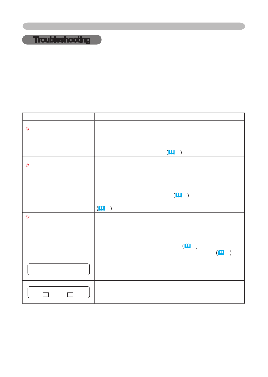
46
Troubleshooting
Troubleshooting
Related messages
When the unit's power is on, messages such as those shown below may be
displayed. When any such message is displayed on the screen, please respond
as described below. If the same message is displayed after the treatment, or if a
message other than the following appears, please contact your dealer or service
company.
Although these messages will be automatically disappeared around several
minutes, it will be reappeared every time the power is turned on.
Message
Description
CHANGE THE LAMP
AFTER REPLACING LAMP,
RESET THE LAMP TIMER.
The time the lamp timer has counted is approaching
2000 hours.
Preparation of a new lamp, and an early lamp change is
recommended. After you have change the lamp, please be
sure to reset the lamp timer.
(
3
9
)
CHANGE THE LAMP
AFTER REPLACING LAMP,
RESET THE LAMP TIMER.
THE POWER WILL TURN OFF
AFTER ** hr.
The time the lamp timer has counted is approaching
2000 hours, so a lamp change within
**
hours is
recommended.
When lamp usage reaches 2000 hours, the power will
automatically be turned off. Please change the lamp by
referring to the section “Lamp”.
(
41
)
After you have
changed the lamp, please be sure to reset the lamp timer.
(
3
9
)
CHANGE THE LAMP
AFTER REPLACING LAMP,
RESET THE LAMP TIMER.
THE POWER WILL TURN OFF
AFTER 0 hr.
As the time the lamp timer has counted has reached
2000 hours, the power will soon be automatically
turned off.
Please immediately turn the power off, and change the lamp
by referring to the section “Lamp”.
(
41
)
After changing
the lamp, please be sure to reset the lamp timer.
(
3
9
)
NO INPUT IS DETECTED
ON ***
There is no input signal.
Please confi rm the signal input connection, and the status
of the signal source.
SYNC IS OUT OF RANGE
ON *** fH *****kHz fV *****Hz
ON *** fH *****kHz fV *****Hz
The horizontal or vertical wavelength of the inputted
signal is outside of the response parameters of this unit.
Please confi rm the specs for this unit or the signal source specs.
47
Troubleshooting
Related messages (continued)
Message
Description
CHECK THE AIR FLOW
The internal portion temperature is rising.
Please turn the power OFF, and allow the unit to cool down
at least 20 minutes. After having confi rmed the following
items, please turn the power ON again.
•
Is there blockage of the air passage aperture?
•
Is the air fi lter dirty?
•
Does the peripheral temperature exceed 35°C?
•
If the same indication is displayed after the treatment,
please set the HIGH at the FAN SPEED of the item
SERVICE of the OPTION menu.
CLEAN THE AIR FILTER
POWER OFF FIRST,
THEN CLEAN THE AIR
FILTER.
AFTER CLEANING THE AIR
FILTER,
RESET THE FILTER TIMER.
A note of precaution when cleaning the air fi lter.
Please immediately turn the power OFF, and clean or
change the air fi lter by referring to the “Air Filter” section of
this manual. After you have cleaned or changed the air fi lter,
please be sure to reset the fi lter timer
(
3
9
)
.
NOTE
• A lamp has a fi nite product life. Lamps are characterized by the
fact that, after long hours of usage, a lamp will no longer light up, or the lamp
will break or burst, etc. This projector is equipped with an automatic shut-down
function, such that the power will automatically be turned off when lamp usage
time has reached 2000 hours. Please be aware, however, that among lamp
types, there are major differences in product lifetimes; a lamp may thus fail to
light even prior to the functioning of the automatic shut-down function of this
projector.
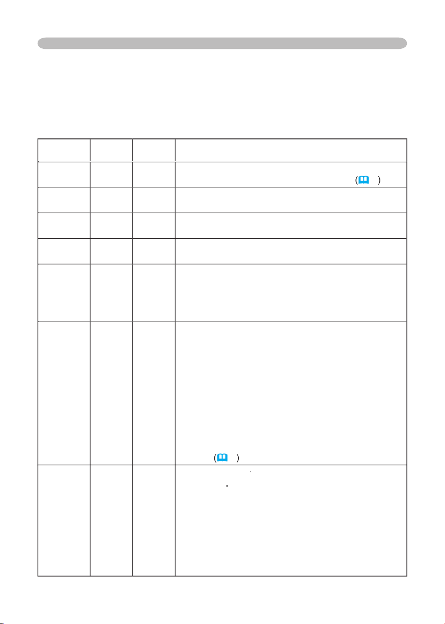
48
Troubleshooting
Regarding the indicator lamps
Lighting and fl ashing of the POWER indicator, the LAMP indicator, and the TEMP
indicator have the meanings as described in the table below. Please respond
in accordance with the instructions within the table. If the same indication is
displayed after the treatment, or if an indication other than the following is
displayed, please contact your dealer or service company.
POWER
indicator
LAMP
indicator
TEMP
indicator
Description
Lighting
In
Orange
Turned
off
Turned
off
The projector is in a standby state.
Please refer to the section “Power On/Off”.
(
16
)
Blinking
In
Green
Turned
off
Turned
off
The projector is warming up.
Please wait.
Lighting
In
Green
Turned
off
Turned
off
The projector is in an on state.
Ordinary operations may be performed.
Blinking
In
Orange
Turned
off
Turned
off
The projector is cooling down.
Please wait.
Blinking
In
Red
(discre-
tionary)
(discre-
tionary)
The projector is cooling down. A certain error
has been detected.
Please wait until the POWER indicator fi nishes blink,
and then perform the proper response measure using
the item descriptions below as reference.
Blinking
In
Red
or
Lighting
In
Red
Lighting
In
Red
Turned
off
The lamp does not light, and there is a
possibility that interior portion has become
heated.
Please turn the power off, and allow the unit to cool
down at least 20 minutes. After the projector has
suffi ciently cooled down, please make confi rmation of
the following items, and then turn the power on again.
• Is there blockage of the air passage aperture?
• Is the air fi lter dirty?
• Does the peripheral temperature exceed 35°C?
If the same indication is displayed after the treatment,
please change the lamp by referring to the section
“Lamp”.
(
41
)
Blinking
In
Red
or
Lighting
In
Red
Blinking
In
Red
Turned
off
The lamp cover
has not been properly fi xed
The lamp cover has not been properly fi xed The lamp cover
(attached)
.
Please turn the power off, and allow the unit to cool
down at least 45 minutes.
After the projector has
suffi ciently cooled down, please make confi rmation
of the attachment state of the lamp cover. After
performing any needed maintenance, turn the power
on again.
If the same indication is displayed after
the treatment, please contact your dealer or service
company.
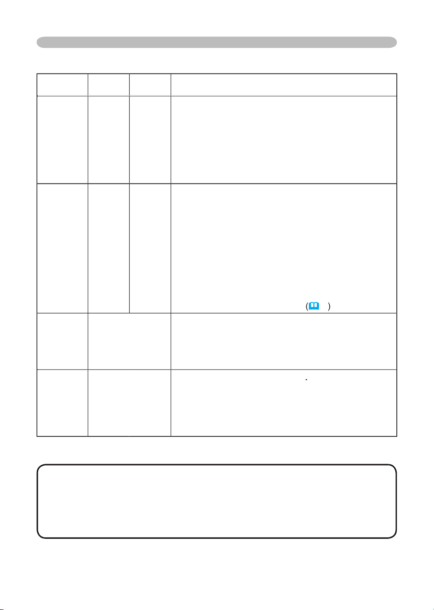
49
Troubleshooting
Regarding the indicator lamps (continued)
POWER
indicator
LAMP
indicator
TEMP
indicator
Description
Blinking
In
Red
or
Lighting
In
Red
Turned
off
Blinking
In
Red
The cooling fan is not operating.
Please turn the power off, and allow the unit to cool
down at least 20 minutes.
After the projector has
suffi ciently cooled down, please make confi rmation
that no foreign matter has become caught in the fan,
etc. and then turn the power on again.
If the same indication is displayed after the treatment,
please contact your dealer or service company.
Blinking
In
Red
or
Lighting
In
Red
Turned
off
Lighting
In
Red
There is a possibility that the interior portion
has become heated.
Please turn the power off, and allow the unit to cool
down at least 20 minutes. After the projector has
suffi ciently cooled down, please make confi rmation of
the following items, and then turn the power on again.
•
Is there blockage of the air passage aperture?
•
Is the air fi lter dirty?
•
Does the peripheral temperature exceed 35°C?
If the same indication is displayed after the treatment,
please set the HIGH at the FAN SPEED of the item
SERVICE of the OPTION menu.
(
4
0
)
Lighting
In
Green
Alternative
blinking in
Red
There is a possibility that the interior portion
has become overcooled.
Please use the unit within the usage temperature
parameters (5°C to 35°C). After the treatment, resent
the power to ON.
Lighting
In
Green
Simultaneous
blinking in
Red
It is time to clean the air
fi lter
.
Please immediately turn the power OFF, and clean
or change the air fi lter by referring to the section “Air
Filter”. After cleaning or changed the air fi lter, please
be sure to reset the fi lter timer. After the treatment,
resent the power to ON.
NOTE
• When the interior portion has become overheated, for safety
purposes, the power source is automatically turned off, and the indicator lamps
may also be turned off. In such a case, press the “
” (OFF) side of the power
switch, and wait at least 45 minutes. After the projector has suffi ciently cooled
down, please make confi rmation of the attachment state of the lamp and lamp
cover, and then turn the power on again.
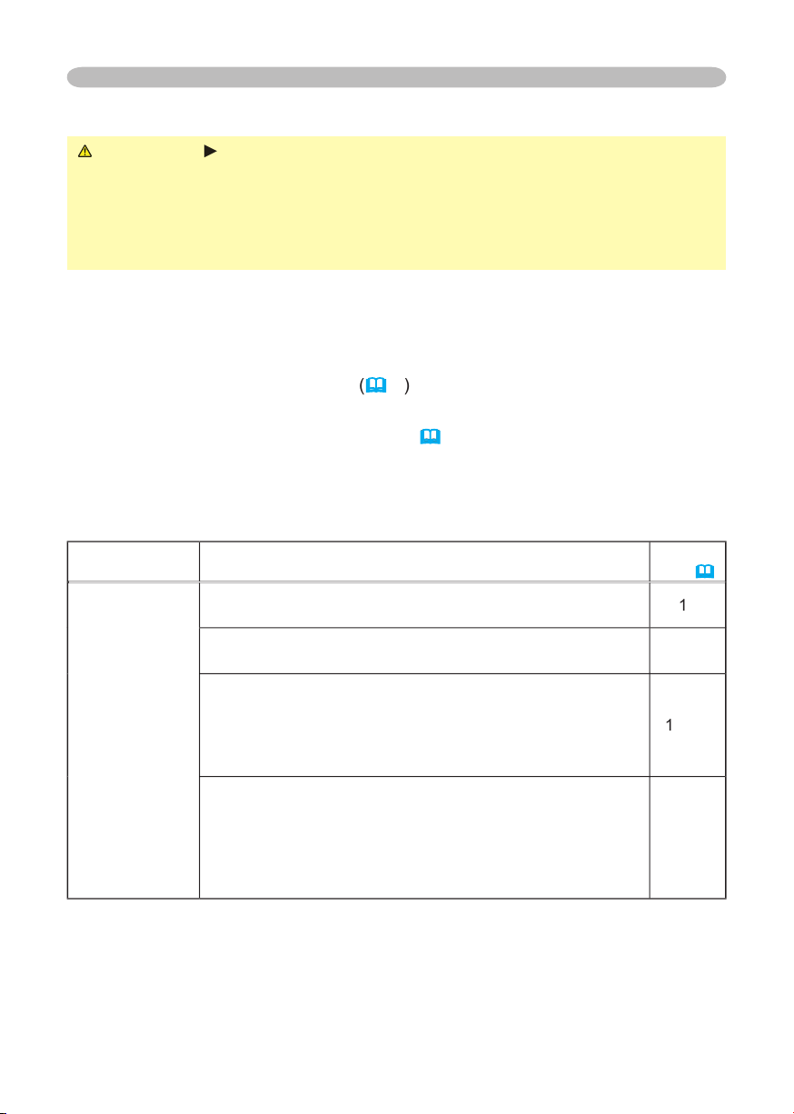
50
Troubleshooting
Phenomena that may easily be mistaken for machine defects
WARNING
►
Never use the projector if abnormal operations such as
smoke, strange odor, excessive sound, damaged casing or elements or cables,
penetration of liquids or foreign matter, etc. should occur. In such cases,
immediately turn off the power switch and then disconnect the power plug from
the power outlet. After making sure that the smoke or odor has stopped, contact
your dealer or service company.
1.
Before requesting repair, please check in accordance with the following chart.
This operation sometimes resolves your problem.
If the situation cannot be corrected,
2.
The projector’s microprocessor may need to be reset. Please push the restart
switch by using a pin or similar.
(
17
)
3.
Some setting may be wrong. Please use the FACTORY RESET function of
SERVICE menu in the OPTION menu
(
40
)
to reset all settings to factory
default.
Then, if the problem is not removed after maintenance, please contact your dealer
or service company.
Phenomenon
Cases not involving a machine defect
Reference
page
Power does not
come on.
The electrical power cord is not plugged in.
Correctly connect the power cord.
1
5
The power switch is not set to the on position.
Set the power switch to [ | ] (On).
16
The main power source has been interrupted during
operation such as by a power outage (blackout), etc.
Please turn the power off, and allow the unit to cool down at
least 20 minutes. After the projector has suffi ciently cooled
down, please turn the power on again.
1
6
, 17
Either there is no lamp and/or lamp cover, or either
of these has not been properly fi xed.
Please turn the power off, and allow the unit to cool down at
least 45 minutes. After the projector has suffi ciently cooled
down, please make confi rmation of the attachment state of
the lamp and lamp cover, and then turn the power on again.
41, 42
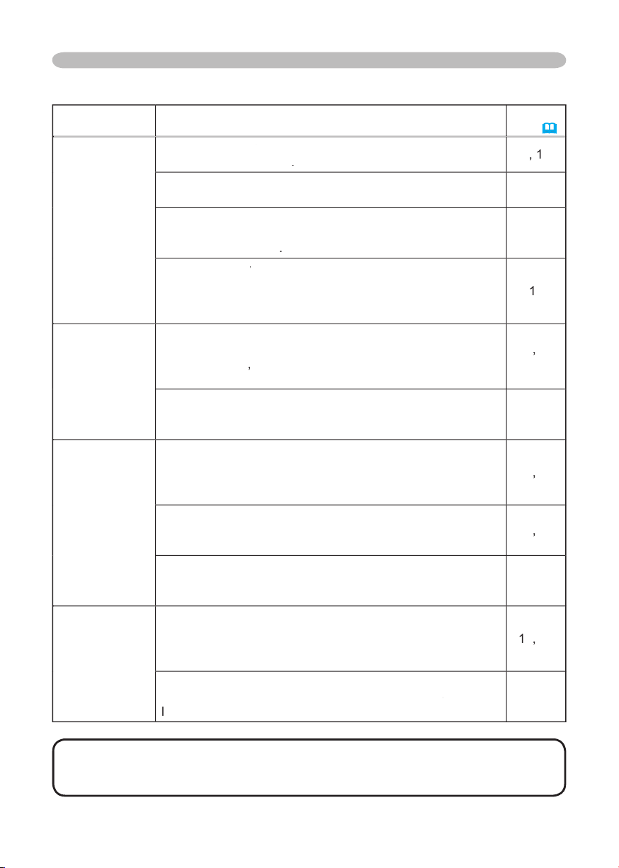
51
Phenomena that may easily be mistaken for machine defects (continued)
Phenomenon
Cases not involving a machine defect
Reference
page
No pictures are
displayed.
The lens
cover
is closed.
cover is closed.cover
Remove the lens
cover
.
4
,
1
6
The signal cables are not correctly connected.
Correctly connect the connection cables.
13, 14
The brightness is adjusted to an extremely low level.
Adjust the BRIGHT to a higher level using the menu function
or the remote control
.
25, 27
The
computer
cannot detect the projector as a plug
computer cannot detect the projector as a plug computer
and play monitor.
Make sure that the
computer’s
can detect a plug and play
monitor using other plug and play monitor.
1
3
Colors have a
faded- out
appearance, or
Color tone is
poor.
Color settings are not correctly adjusted.
Perform picture adjustments by changing the COLOR
TEMP,
COLOR
,
TINT and/or
COLOR SPAC
E
settin
gs,
using the menu functions.
2
5
,
28
32
COLOR SPACE setting is not suitable.
Change the COLOR SPACE setting to AUTO, RGB,
SMPTE240 , REC709 or REC601.
3
2
Pictures appear
dark.
The brightness and/or contrast are adjusted to an
extremely low level.
Adjust the BRIGHT and/or CONTRAST settings to a higher
level using the menu function.
2
5
,
2
7
The WHISPER function is working.
Select the NORMAL to the item WHISPER in the SETUP
menu.
2
6
,
3
4
The lamp is approaching the end of its product
lifetime.
Replace the lamp.
41, 42,
44
Pictures appear
blurry.
Either the focus and/or horizontal phase settings are
not properly.
Adjust the focus using the focus
ring
, and/or H PHASE
using the menu function.
1
9
,
30
The lens is dirty or misty.
Clean the lens by referring to the section “
Carin
g
f
or
for f
t
he
l
en
s
”.
4
5
Troubleshooting
NOTE
• Although bright spots or dark spots may appear on the screen, this
is a unique characteristic of liquid crystal displays, and such do not constitute or
imply a machine defect.
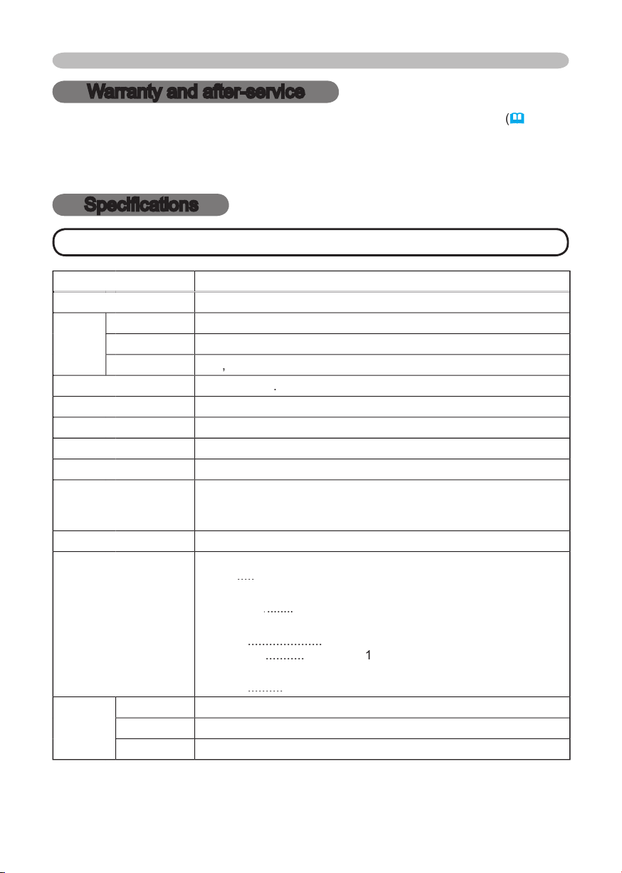
52
Specifi cations
NOTE
• This specifi cations are subject to change without notice.
Warranty and after-service / Specifi cations
Warranty and after-service
If a problem occurs with the equipment, fi rst refer to the “Troubleshooting”
(
46
)
and
run through the suggested checks. If this does not resolve the problem, please contact
your dealer or the service company. They will tell you what warranty condition is
applied.
Item
Specifi cation
Product name
Liquid crystal projector
Liquid
Crystal
panel
Panel size
1.5 cm (0.6 type)
Drive system
TFT active matrix
Pixels
786
,
432
pixels (
1024
horizontal x
768
vertical)
Lens
F=
1.
77
f=
2
0
.
4
mm
Lamp
165
W UHB
Power Supply
AC100-120V
/
2.7
A, AC220-240V/
1.5
A
Power Consumption
240
W
Temperature range
5 ~ 35°C (Operating)
Size
285
(W) x
73
(H) x
2
02
(D) mm
(Not including protruding parts)
• Please refer to the following fi gure.
Weight (mass)
2.2
kg
Ports
Optional
parts
Lamp
DT00701
Air fi lter
NJ20922
Others
• Please consult your dealer.
RGB input:
RGB
.....
D-sub 15pin mini x 1
Communication port:
CONTROL
........
CONTROL ........ CONTROL
D-sub 9pin x 1
Video input:
VIDEO
.....................
RCA x 1
S-VIDEO
...........
S-Video
x
1
Audio input:
AUDIO
..........
Stereo mini x 1
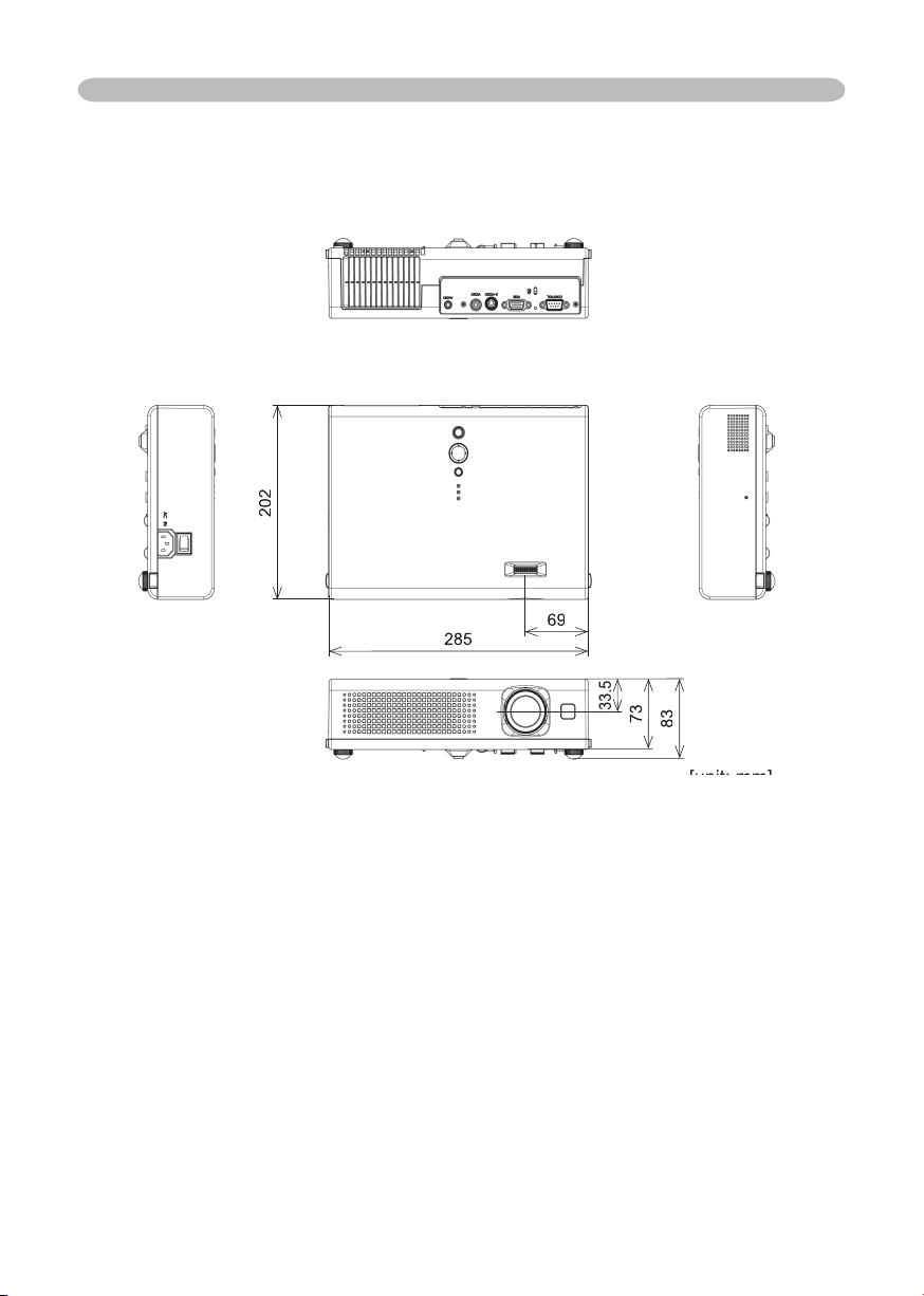
53
Specifi cations
Specifi cations (continued)
[unit: mm]
[unit: mm]
202
285
69
33.5
73
83

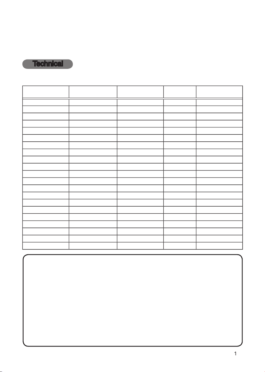
1
Projector
User's Manual – Operating Guide
Technical
Example of computer signal
Resolution (H x V)
H. frequency (kHz)
V. frequency (Hz)
Rating
Signal mode
720 x 400
37.9
85.0
VESA
TEXT
640 x 480
31.5
59.9
VESA
VGA (60Hz)
640 x 480
37.9
72.8
VESA
VGA (72Hz)
640 x 480
37.5
75.0
VESA
VGA (75Hz)
640 x 480
43.3
85.0
VESA
VGA (85Hz)
800 x 600
35.2
56.3
VESA
SVGA (56Hz)
800 x 600
37.9
60.3
VESA
SVGA (60Hz)
800 x 600
48.1
72.2
VESA
SVGA (72Hz)
800 x 600
46.9
75.0
VESA
SVGA (75Hz)
800 x 600
53.7
85.1
VESA
SVGA (85Hz)
832 x 624
49.7
74.5
Mac 16” mode
1024 x 768
48.4
60.0
VESA
XGA (60Hz)
1024 x 768
56.5
70.1
VESA
XGA (70Hz)
1024 x 768
60.0
75.0
VESA
XGA (75Hz)
1024 x 768
68.7
85.0
VESA
XGA (85Hz)
1152 x 864
67.5
75.0
VESA
SXGA (75Hz)
1280 x 960
60.0
60.0
VESA
SXGA (60Hz)
1280 x 1024
64.0
60.0
VESA
SXGA (60Hz)
1280 x 1024
80.0
75.0
VESA
SXGA (75Hz)
1280 x 1024
91.1
85.0
VESA
SXGA (85Hz)
1600 x 1200
75.0
60.0
VESA
UXGA (60Hz)
NOTE
• Be sure to check jack type, signal level, timing and resolution
before connecting this projector to a computer.
• Some computers may have multiple display screen modes. Use of some of
these modes will not be possible with this projector.
• Depending on the input signal, full-size display may not be possible in some
cases. Refer to the number of display pixels above.
• Although the projector can display signals with resolution up to UXGA
(1600x1200), the signal will be converted to the projector’s panel resolution
before being displayed. The best display performance will be achieved if the
resolutions of the input signal and projector panel are identical.
• Automatically adjustment may not function correctly with some input signals.
• The image may not be displayed correctly when the input sync signal is a
composite sync or a sync on G.
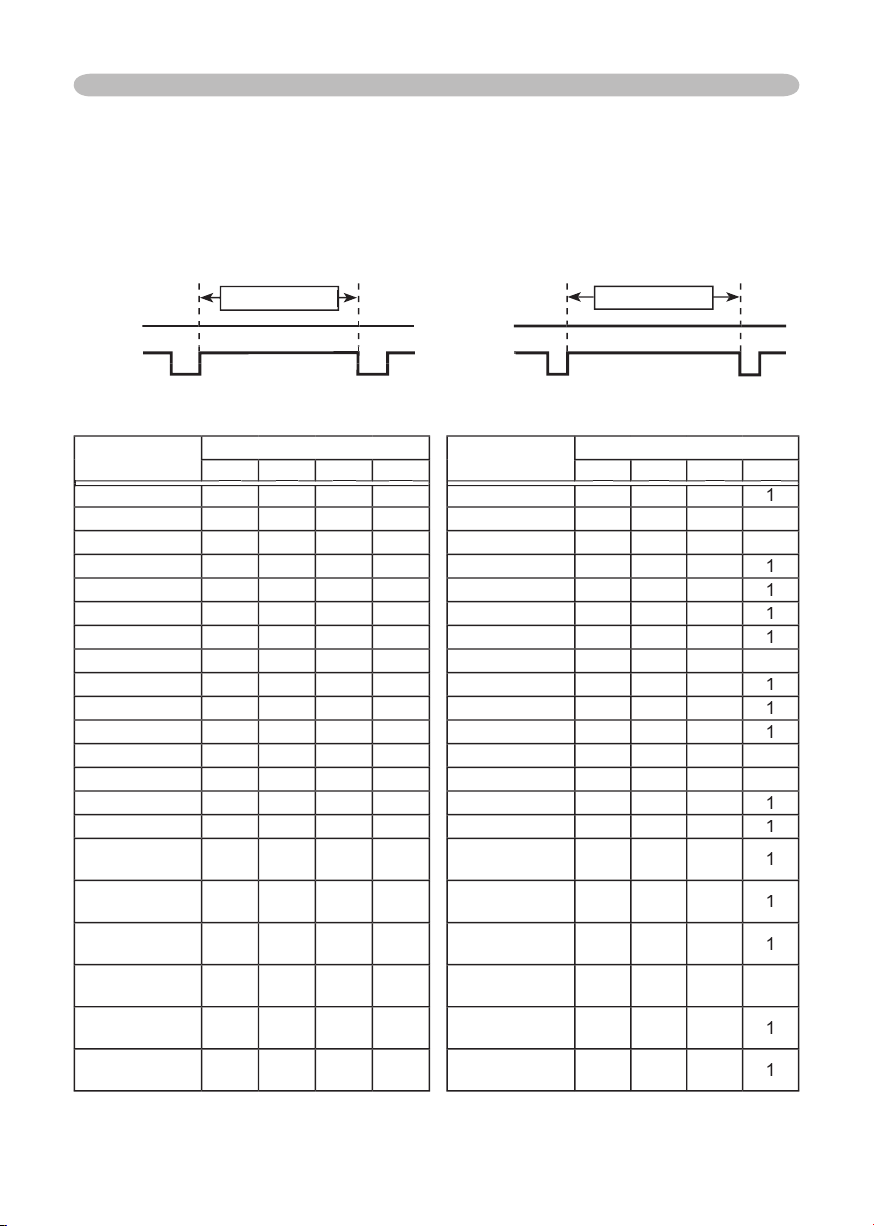
2
Technical (continued)
Initial set signals
The following signals are used for the initial settings. The signal timing of some
computer models may be different. In such case, adjust the items V POSITION
and H POSITION in the IMAGE menu.
Back porch (B) Front porch (D) Back porch (b) Front porch (d)
Display interval (C)
Display interval (c)
Data Data
H. Sync. V. Sync.
Sync (A) Sync (a)
Computer/
Signal
Horizontal signal timing (μs)
Computer/
Signal
Vertical signal timing (lines)
(A)
(A)
(A)
(B)
(B)
(B)
(C)
(C)
(C)
(D)
(D)
(D)
(a)
(a)
(a)
(b)
(b)
(b)
(c)
(c)
(c)
(d)
(d)
(d)
TEXT
2.0
3.0
20.3
1.0
TEXT
3
42
400
1
VGA (60Hz)
3.8
1.9
25.4
0.6
VGA (60Hz)
2
33
480
10
VGA (72Hz)
1.3
3.8
20.3
1.0
VGA (72Hz)
3
28
480
9
VGA (75Hz)
2.0
3.8
20.3
0.5
VGA (75Hz)
3
16
480
1
VGA (85Hz)
1.6
2.2
17.8
1.6
VGA (85Hz)
3
25
480
1
SVGA (56Hz)
2.0
3.6
22.2
0.7
SVGA (56Hz)
2
22
600
1
SVGA (60Hz)
3.2
2.2
20.0
1.0
SVGA (60Hz)
4
23
600
1
SVGA (72Hz)
2.4
1.3
16.0
1.1
SVGA (72Hz)
6
23
600
37
SVGA (75Hz)
1.6
3.2
16.2
0.3
SVGA (75Hz)
3
21
600
1
SVGA (85Hz)
1.1
2.7
14.2
0.6
SVGA (85Hz)
3
27
600
1
Mac 16" mode
1.1
3.9
14.5
0.6
Mac 16" mode
3
39
624
1
XGA (60Hz)
2.1
2.5
15.8
0.4
XGA (60Hz)
6
29
768
3
XGA (70Hz)
1.8
1.9
13.7
0.3
XGA (70Hz)
6
29
768
3
XGA (75Hz)
1.2
2.2
13.0
0.2
XGA (75Hz)
3
28
768
1
XGA (85Hz)
1.0
2.2
10.8
0.5
XGA (85Hz)
3
36
768
1
1152 x 864
(75Hz)
1.2
2.4
10.7
0.6
1152 x 864
(75Hz)
3
32
864
1
1280 x 960
(60Hz)
1.0
2.9
11.9
0.9
1280 x 960
(60Hz)
3
36
960
1
1280 x 1024
(60Hz)
1.0
2.3
11.9
0.4
1280 x 1024
(60Hz)
3
38
1024
1
1280 x 1024
(75Hz)
1.1
1.8
9.5
0.2
1280 x 1024
(75Hz)
3
37
1024
2
1280 x 1024
(85Hz)
1.0
1.4
8.1
0.4
1280 x 1024
(85Hz)
3
44
1024
1
1600 x 1200
(60Hz)
1.2
1.9
9.9
0.4
1600 x 1200
(60Hz)
3
46
1200
1
Data Data
H. Sync. V. Sync.
Data Data
Data Data
Data Data
H. Sync. V. Sync.
Data Data
Data Data
Data Data
H. Sync. V. Sync.
H. Sync. V. Sync.
H. Sync. V. Sync.
Display interval (C)
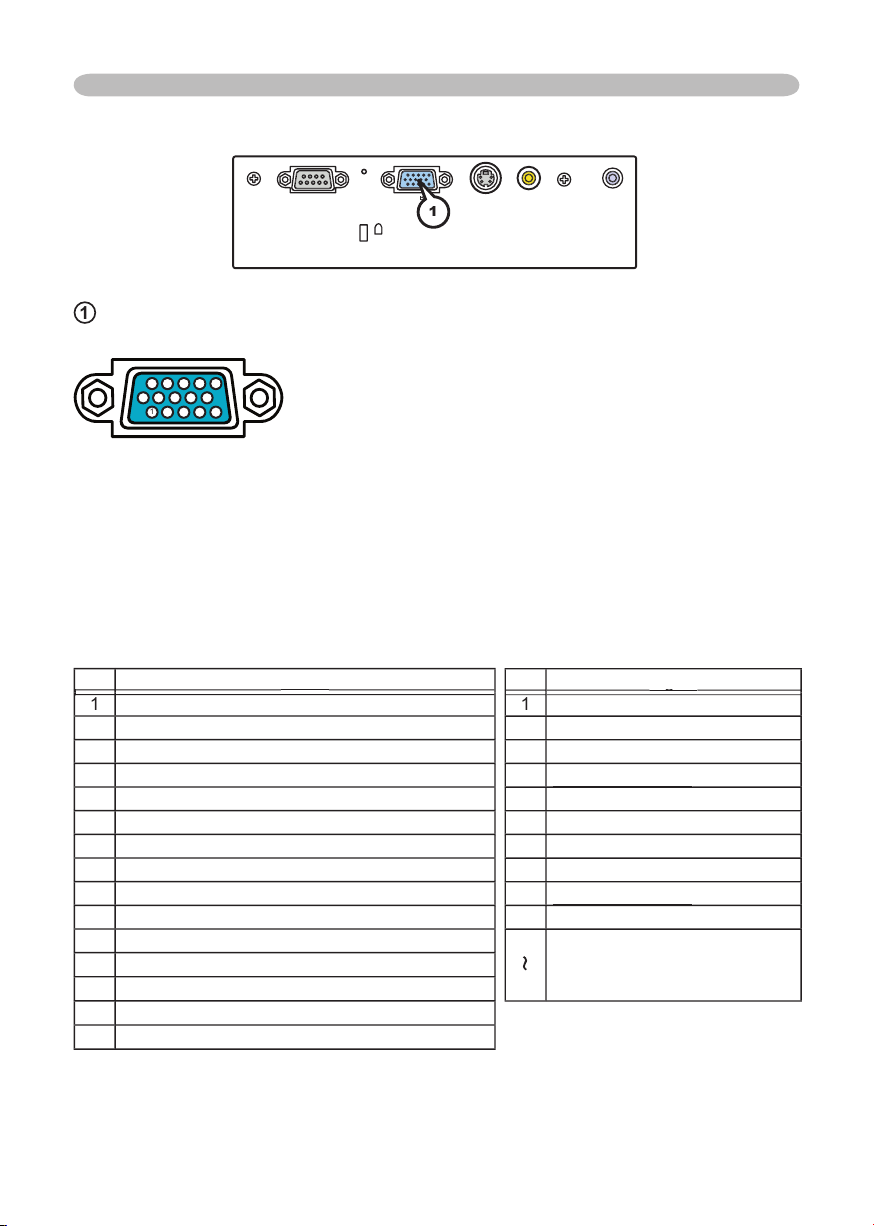
3
Technical (continued)
Connection to the ports
S-VIDE
O
VIDEO
AUDIO
RG
B
CONTRO
L
K
K
1
RGB
D-sub 15pin mini shrink jack
At RGB signal
• Vid
eo signal: RGB separate, Analog, 0.7Vp-p, 75Ω terminated (positive)
• H/V. sync. Signal: TTL level (positive/negative)
• Com
posite sync. Signal: TTL level
At component video signal
• System: 525i (480i), 525p (480p), 625i (576i), 750p (720p), 1125i (1080i)
At RGB signal At component video signal
Pin
Signal
Signal
1
Video Red
2
Video Green
3
Video Blue
4
(No connection)
5
Ground
6
Ground Red
7
Ground Green
8
Ground Blue
9
(No connection)
10
Ground
11
(No connection)
12
SDA (DDC data)
13
H. sync / Composite sync.
14
V. sync.
15
SCL (DDC clock)
1
Pin
Signal
Signal
1
C
R
/P
R
2
Y
3
C
B
/P
B
4
(No connection)
(No connection)
5
Ground
6
C
R
/P
R
Ground
7
Y Ground
8
C
B
/P
B
Ground
9
(No connection)
(No connection)
10
Ground
11
15
(No connection)
* except for RGB OUT.
11
12
12
13
13
14
14
15
15
1
2
3
4
5
6
7
8
9
10
10
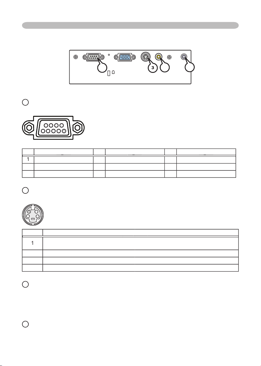
4
Technical (continued)
Connection to the ports (continued)
2
CONTROL
D-sub 9pin plug
• About the details of RS-232C communication, please refer to the following page.
Pin
Signal
Signal
Signal
Signal
Pin
Signal
Signal
Signal
Signal
Pin
Signal
Signal
Signal
Signal
1
(No connection)
4
(No connection)
7
RTS
2
RD
5
Ground
8
CTS
3
TD
6
(No connection)
9
(No connection)
3
S-VIDEO
Mini DIN 4pin jack
4
4
4
3
3
3
22
1
1
Pin
Signal
Signal
Signal
Signal
1
Color signal 0.286Vp-p (NTSC, burst), 75Ω terminator
Color signal 0.300Vp-p (PAL/SECAM, burst) 75Ω terminator
2
Brightness signal, 1.0Vp-p, 75Ω terminator
3
Ground
4
Ground
4
4
VIDEO
RCA jack
• System: NTSC, PAL, SECAM, PAL-M, PAL-N, NTSC4.43, PAL60
• 1.0±0.1Vp-p, 75Ω terminator
5
AUDIO
AUDIO
Ø3.5 stereo mini jack
• 200 mV rms, more than 47k Ω or more
S-VIDEO
VIDEO
AUDIO
RGB
CONTROL
K
3
4
5
2
9
8
7
6
5
4
3
2
1
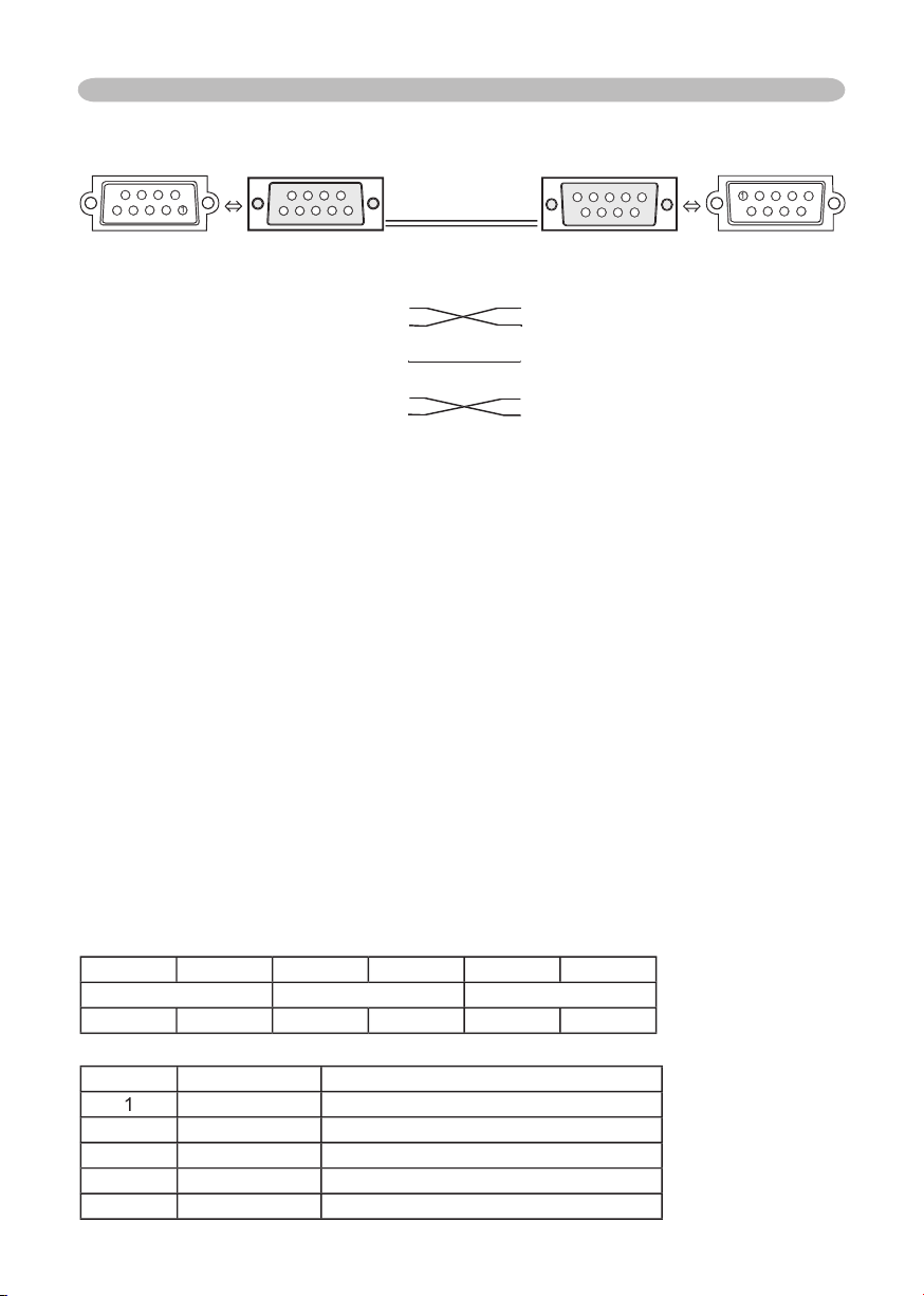
5
Technical (continued)
RS-232C Communication
6
6
6
7
7
7
8
8
9
9
1
2
2
3
3
4
4
4
5
5
5
6
6
7
7
7
8
8
9
9
9
1
2
3
4
4
5
CONTROL port RS-232C cable RS-232C port
of the projector of the computer
- (1) (1) CD
RD (2) (2) RD
TD (3) (3) TD
- (4) (4) DTR
GND (5) (5) GND
- (6) (6) DSR
RTS (7) (7) RTS
CTS (8) (8) DTS
- (9) (9) RI
Connecting the cable
1.
Turn off the projector and the computer.
2.
Connect the CONTROL port of the projector with a RS-232C port of the
computer by a RS-232C cable. Use the cable that fulfills the specification
shown in the previous page.
3.
Turn the computer on, and after the computer has started up turn the
projector on.
Communications setting
19200bps, 8N1
1. Protocol
Consist of header (7 bytes) + command data (6 bytes).
2. Header
BE + EF + 03 + 06 + 00 + CRC_low + CRC_high
CRC_low : Lower byte of CRC fl ag for command data
CRC_high : Upper byte of CRC fl ag for command data
3. Command data
Command data chart
byte_0
byte_1
byte_2
byte_3
byte_4
byte_5
Action
Type
Setting code
low
high
low
high
low
high
Action (byte_0 - 1)
Action
Classifi cation
Content
1
SET
Change setting to desired value.
2
GET
Read projector internal setup value.
4
INCREMENT
Increment setup value by 1.
5
DECREMENT
Decrement setup value by 1.
6
EXECUTE
Run a command.
RD (2) (2) RD
TD (3) (3) TD
RD (2) (2) RD
TD (3) (3) TD
RD (2) (2) RD
GND (5) (5) GND
RTS (7) (7) RTS
CTS (8) (8) DTS
RTS (7) (7) RTS
CTS (8) (8) DTS
RTS (7) (7) RTS

6
Technical (continued)
Requesting projector status (Get command)
(1) Send the request code Header + Command data (‘02H’+‘00H’+ type (2 bytes)+
‘00H’ +‘00H’) from the computer to the projector.
(2) The projector returns the response code ‘1DH’+ data (2 bytes) to the computer.
Changing the projector settings (Set command)
(1) Send the setting code Header + Command data (‘01H’+‘00H’+ type (2 bytes) +
setting code (2 bytes)) from the computer to the projector.
(2) The projector changes the setting based on the above setting code.
(3) The projector returns the response code ‘06H’ to the computer.
Using the projector default settings (Reset Command)
(1) The computer sends the default setting code Header + Command data (‘06H’+
‘00H’ + type (2 bytes) +‘00H’+‘00H’) to the projector.
(2) The projector changes the specifi ed setting to the default value.
(3) The projector returns the response code ‘06H’ to the computer.
Increasing the projector setting value (Increment command)
(1) The computer sends the increment code Header + Command data (‘04H’+
‘00H’+ type (2 bytes) +‘00H’+‘00H’) to the projector.
(2) The projector in creases the setting value on the above setting code.
(3) The projector returns the response code ‘06H’ to the computer.
Decreasing the projector setting value (Decrement command)
(1) The computer sends the decrement code Header + Command data (‘05H’+
‘00H’+ type (2 bytes) +‘00H’ + ‘00H’) to the projector.
(2) The projector decreases the setting value on the above setting code.
(3) The projector returns the response code ‘06H’ to the computer.
When the projector cannot understand the received command
When the projector cannot understand the received command, the error code ‘15H’
is sent back to the computer.
Sometimes the projector cannot properly receive the command. In such a
case, the command is not executed and the error code ‘15H’ is sent back to the
computer. If this error code is returned, send the same command again.
When the projector cannot execute the received command.
When the projector cannot execute the received command, the error code ‘1cH’
+ ‘xxxxH’ is sent back to the computer. When the data length is greater than
indicated by the data length code, the projector ignore the excess data code.
Conversely when the data length is shorter than indicated by the data length
code, an error code will be returned to the computer.
NOTE
• Operation cannot be guaranteed when the projector receives an undefi ned
command or data.
• Provide an interval of at least 40ms between the response code and any other code.
• The projector outputs test data when the power supply is switched ON, and when the
lamp is lit. Ignore this data.
• Commands are not accepted during warm-up.
• Commands are not accepted during warm-up.
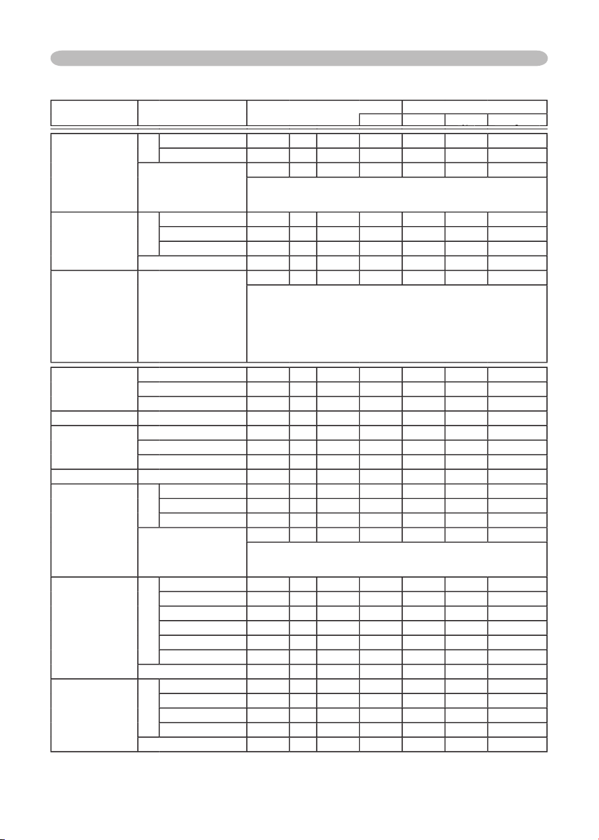
7
Technical (continued)
Command table
Names
Operation Type
Header
Command Data
CRC
Action
Type
Type
Type
Setting Code
Setting Code
Setting Code
Power
Set
Turn off
BE EF
03
06 00
2A D3
01 00
00 60
00 00
Turn on
BE EF
03
06 00
BA D2
01 00
00 60
01 00
Get
BE EF
03
06 00
19 D3
02 00
00 60
00 00
(Example return)
00 00 01 00 02 00
(Off) (On) (Cool down)
Input Source
Set
RGB
BE EF
03
06 00
FE D2
01 00
00 20
00 00
VIDEO
BE EF
03
06 00
6E D3
01 00
00 20
01 00
S-VIDEO
BE EF
03
06 00
9E D3
01 00
00 20
02 00
Get
BE EF
03
06 00
CD D2
02 00
00 20
00 00
Error Status
Get
BE EF
03
06 00
D9 D8
02 00
20 60
00 00
(Example return)
00 00 01 00 02 00 03 00
(Normal) (Cover error) (Fan error) (Lamp error)
04 00 05 00 06 00 07 00
(Temp error) (Air fl ow error) (Lamp time error) (Cool error)
08 00
09 00 10 00
(Filter error)
(Filter missing error) (Inner Sencer error)
BRIGHT
Get
BE EF
03
06 00
89 D2
02 00
03 20
00 00
Increment
BE EF
03
06 00
EF D2
04 00
03 20
00 00
Decrement
BE EF
03
06 00
3E D3
05 00
03 20
00 00
BRIGHT Reset
Execute
BE EF
03
06 00
58 D3
06 00
00 70
00 00
CONTRAST
Get
BE EF
03
06 00
FD D3
02 00
04 20
00 00
Increment
BE EF
03
06 00
9B D3
04 00
04 20
00 00
Decrement
BE EF
03
06 00
4A D2
05 00
04 20
00 00
CONTRAST Reset
Execute
BE EF
03
06 00
A4 D2
06 00
01 70
00 00
MODE
Set
NORMAL
BE EF
03
06 00
23 F6
01 00
BA 30
00 00
CINEMA
BE EF
03
06 00
B3 F7
01 00
BA 30
01 00
DYNAMIC
BE EF
03
06 00
E3 F4
01 00
BA 30
04 00
Get
BE EF
03
06 00
10 F6
02 00
BA 30
00 00
(Example return)
00 00 01 00 04 00 10 00
(Normal) (Cinema) (Dynamic) (Custom)
GAMMA
Set
#1 DEFAULT
BE EF
03
06 00
07 E9
01 00
A1 30
20 00
#1 CUSTOM
BE EF
03
06 00
07 FD
01 00
A1 30
10 00
#2 DEFAULT
BE EF
03
06 00
97 E8
01 00
A1 30
21 00
#2 CUSTOM
BE EF
03
06 00
97 FC
01 00
A1 30
11 00
#3 DEFAULT
BE EF
03
06 00
67 E8
01 00
A1 30
22 00
#3 CUSTOM
BE EF
03
06 00
67 FC
01 00
A1 30
12 00
Get
BE EF
03
06 00
F4 F0
02 00
A1 30
00 00
User Gamma Pattern
Set
Off
BE EF
03
06 00
FB FA
01 00
80 30
00 00
9 step gray scale
BE EF
03
06 00
6B FB
01 00
80 30
01 00
15 steps gray scale
BE EF
03
06 00
9B FB
01 00
80 30
02 00
Ramp
BE EF
03
06 00
0B FA
01 00
80 30
03 00
Get
BE EF
03
06 00
C8 FA
02 00
80 30
00 00
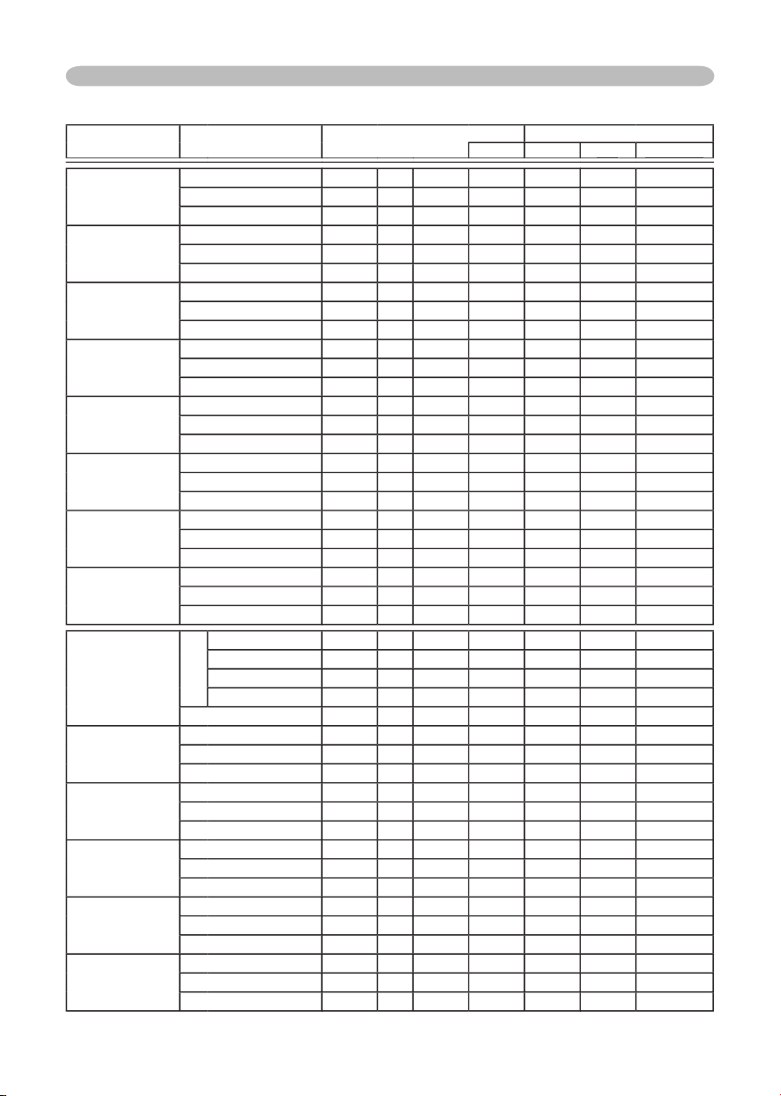
8
Technical (continued)
Command table (continued)
Names
Operation Type
Header
Command Data
CRC
Action
Type
Type
Type
Setting Code
Setting Code
Setting Code
User Gamma Point 1
Get
BE EF
03
06 00
08 FE
02 00
90 30
00 00
Increment
BE EF
03
06 00
6E FE
04 00
90 30
00 00
Decrement
BE EF
03
06 00
BF FF
05 00
90 30
00 00
User Gamma Point 2
Get
BE EF
03
06 00
F4 FF
02 00
91 30
00 00
Increment
BE EF
03
06 00
92 FF
04 00
91 30
00 00
Decrement
BE EF
03
06 00
43 FE
05 00
91 30
00 00
User Gamma Point 3
Get
BE EF
03
06 00
B0 FF
02 00
92 30
00 00
Increment
BE EF
03
06 00
D6 FF
04 00
92 30
00 00
Decrement
BE EF
03
06 00
07 FE
05 00
92 30
00 00
User Gamma Point 4
Get
BE EF
03
06 00
4C FE
02 00
93 30
00 00
Increment
BE EF
03
06 00
2A FE
04 00
93 30
00 00
Decrement
BE EF
03
06 00
FB FF
05 00
93 30
00 00
User Gamma Point 5
Get
BE EF
03
06 00
38 FF
02 00
94 30
00 00
Increment
BE EF
03
06 00
5E FF
04 00
94 30
00 00
Decrement
BE EF
03
06 00
8F FE
05 00
94 30
00 00
User Gamma Point 6
Get
BE EF
03
06 00
C4 FE
02 00
95 30
00 00
Increment
BE EF
03
06 00
A2 FE
04 00
95 30
00 00
Decrement
BE EF
03
06 00
73 FF
05 00
95 30
00 00
User Gamma Point 7
Get
BE EF
03
06 00
80 FE
02 00
96 30
00 00
Increment
BE EF
03
06 00
E6 FE
04 00
96 30
00 00
Decrement
BE EF
03
06 00
37 FF
05 00
96 30
00 00
User Gamma Point 8
Get
BE EF
03
06 00
7C FF
02 00
97 30
00 00
Increment
BE EF
03
06 00
1A FF
04 00
97 30
00 00
Decrement
BE EF
03
06 00
CB FE
05 00
97 30
00 00
COLOR TEMP
Set
LOW
BE EF
03
06 00
6B F4
01 00
B0 30
01 00
MIDDLE
BE EF
03
06 00
9B F4
01 00
B0 30
02 00
HIGH
BE EF
03
06 00
0B F5
01 00
B0 30
03 00
CUSTOM
BE EF
03
06 00
3B F8
01 00
B0 30
10 00
Get
BE EF
03
06 00
C8 F5
02 00
B0 30
00 00
COLOR TEMP GAIN R
Get
BE EF
03
06 00
34 F4
02 00
B1 30
00 00
Increment
BE EF
03
06 00
52 F4
04 00
B1 30
00 00
Decrement
BE EF
03
06 00
83 F5
05 00
B1 30
00 00
COLOR TEMP GAIN G
Get
BE EF
03
06 00
70 F4
02 00
B2 30
00 00
Increment
BE EF
03
06 00
16 F4
04 00
B2 30
00 00
Decrement
BE EF
03
06 00
C7 F5
05 00
B2 30
00 00
COLOR TEMP GAIN B
Get
BE EF
03
06 00
8C F5
02 00
B3 30
00 00
Increment
BE EF
03
06 00
EA F5
04 00
B3 30
00 00
Decrement
BE EF
03
06 00
3B F4
05 00
B3 30
00 00
COLOR TEMP
OFFSET R
Get
BE EF
03
06 00
04 F5
02 00
B5 30
00 00
Increment
BE EF
03
06 00
62 F5
04 00
B5 30
00 00
Decrement
BE EF
03
06 00
B3 F4
05 00
B5 30
00 00
COLOR TEMP
OFFSET G
Get
BE EF
03
06 00
40 F5
02 00
B6 30
00 00
Increment
BE EF
03
06 00
26 F5
04 00
B6 30
00 00
Decrement
BE EF
03
06 00
F7 F4
05 00
B6 30
00 00
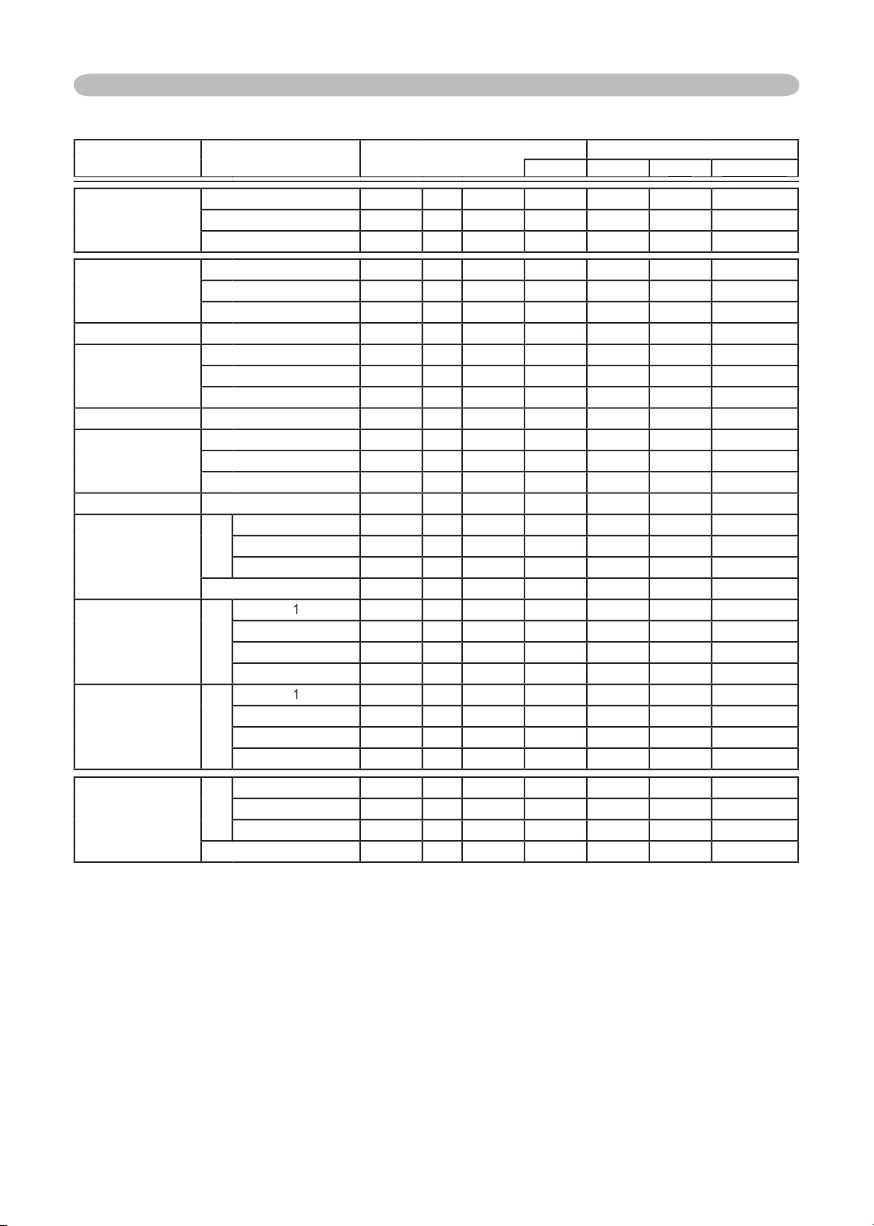
9
Technical (continued)
Command table (continued)
Names
Operation Type
Header
Command Data
CRC
Action
Type
Type
Type
Setting Code
Setting Code
Setting Code
COLOR TEMP
OFFSET B
Get
BE EF
03
06 00
BC F4
02 00
B7 30
00 00
Increment
BE EF
03
06 00
DA F4
04 00
B7 30
00 00
Decrement
BE EF
03
06 00
0B F5
05 00
B7 30
00 00
COLOR
Get
BE EF
03
06 00
B5 72
02 00
02 22
00 00
Increment
BE EF
03
06 00
D3 72
04 00
02 22
00 00
Decrement
BE EF
03
06 00
02 73
05 00
02 22
00 00
COLOR Reset
Execute
BE EF
03
06 00
80 D0
06 00
0A 70
00 00
TINT
Get
BE EF
03
06 00
49 73
02 00
03 22
00 00
Increment
BE EF
03
06 00
2F 73
04 00
03 22
00 00
Decrement
BE EF
03
06 00
FE 72
05 00
03 22
00 00
TINT Reset
Execute
BE EF
03
06 00
7C D1
06 00
0B 70
00 00
SHARPNESS
Get
BE EF
03
06 00
F1 72
02 00
01 22
00 00
Increment
BE EF
03
06 00
97 72
04 00
01 22
00 00
Decrement
BE EF
03
06 00
46 73
05 00
01 22
00 00
SHARPNESS Reset
Execute
BE EF
03
06 00
C4 D0
06 00
09 70
00 00
PROGRESSIVE
Set
TURN OFF
BE EF
03
06 00
4A 72
01 00
07 22
00 00
TV
BE EF
03
06 00
DA 73
01 00
07 22
01 00
FILM
BE EF
03
06 00
2A 73
01 00
07 22
02 00
Get
BE EF
03
06 00
79 72
02 00
07 22
00 00
MY MEMORY Load
Set
1
BE EF
03
06 00
0E D7
01 00
14 20
00 00
2
BE EF
03
06 00
9E D6
01 00
14 20
01 00
3
BE EF
03
06 00
6E D6
01 00
14 20
02 00
4
BE EF
03
06 00
FE D7
01 00
14 20
03 00
MY MEMORY Save
Set
1
BE EF
03
06 00
F2 D6
01 00
15 20
00 00
2
BE EF
03
06 00
62 D7
01 00
15 20
01 00
3
BE EF
03
06 00
92 D7
01 00
15 20
02 00
4
BE EF
03
06 00
02 D6
01 00
15 20
03 00
ASPECT
Set
4:3
BE EF
03
06 00
9E D0
01 00
08 20
00 00
16:9
BE EF
03
06 00
0E D1
01 00
08 20
01 00
NORMAL
BE EF
03
06 00
5E DD
01 00
08 20
10 00
Get
BE EF
03
06 00
AD D0
02 00
08 20
00 00
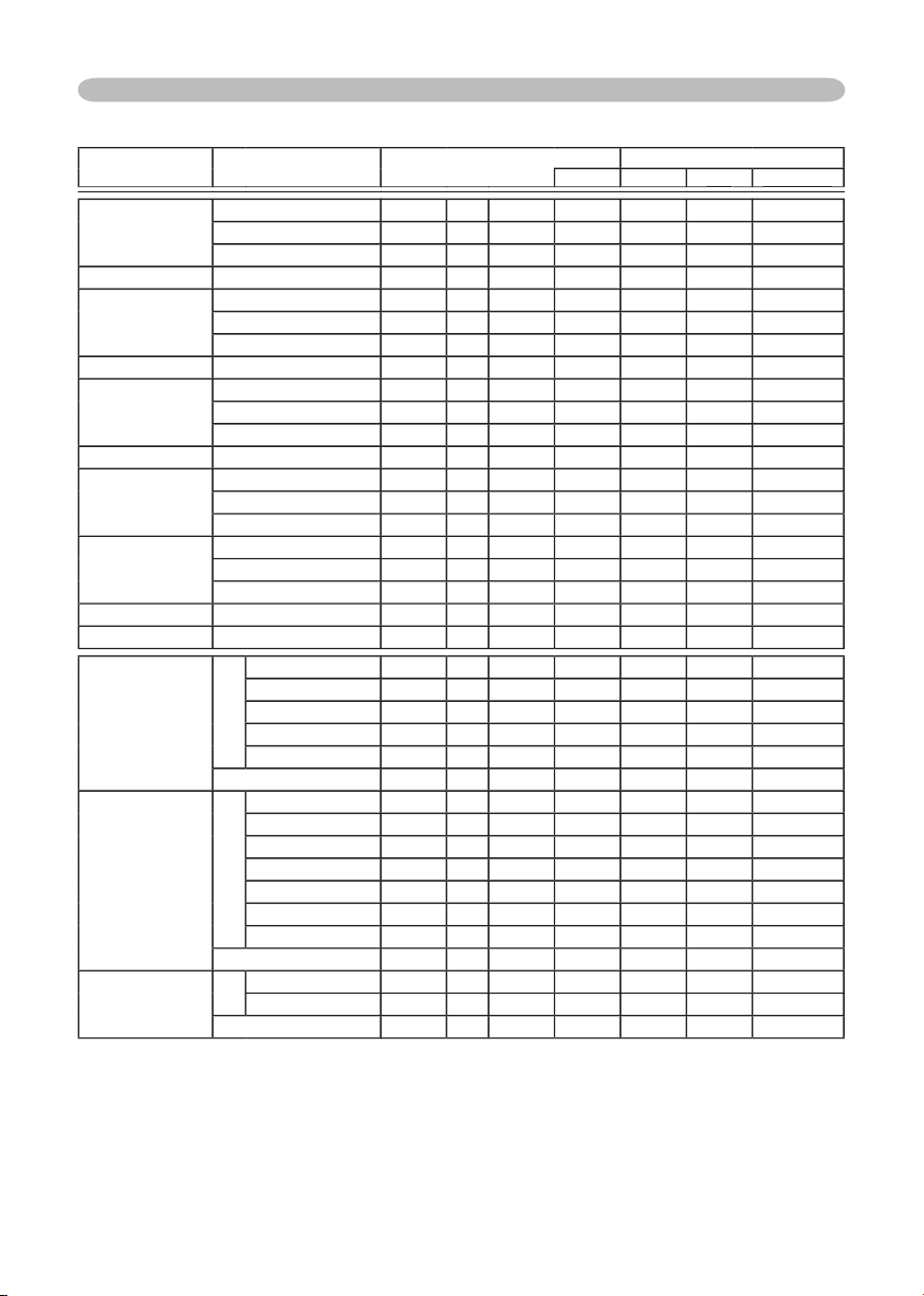
10
Technical (continued)
Command table (continued)
Names
Operation Type
Header
Command Data
CRC
Action
Type
Type
Type
Setting Code
Setting Code
Setting Code
OVER SCAN
Get
BE EF
03
06 00
91 70
02 00
09 22
00 00
Increment
BE EF
03
06 00
F7 70
04 00
09 22
00 00
Decrement
BE EF
03
06 00
26 71
05 00
09 22
00 00
OVER SCAN Reset
Execute
BE EF
03
06 00
EC D9
06 00
27 70
00 00
V POSITION
Get
BE EF
03
06 00
0D 83
02 00
00 21
00 00
Increment
BE EF
03
06 00
6B 83
04 00
00 21
00 00
Decrement
BE EF
03
06 00
BA 82
05 00
00 21
00 00
V POSITION Reset
Execute
BE EF
03
06 00
E0 D2
06 00
02 70
00 00
H POSITION
Get
BE EF
03
06 00
F1 82
02 00
01 21
00 00
Increment
BE EF
03
06 00
97 82
04 00
01 21
00 00
Decrement
BE EF
03
06 00
46 83
05 00
01 21
00 00
H POSITION Reset
Execute
BE EF
03
06 00
1C D3
06 00
03 70
00 00
H PHASE
Get
BE EF
03
06 00
49 83
02 00
03 21
00 00
Increment
BE EF
03
06 00
2F 83
04 00
03 21
00 00
Decrement
BE EF
03
06 00
FE 82
05 00
03 21
00 00
H SIZE
Get
BE EF
03
06 00
B5 82
02 00
02 21
00 00
Increment
BE EF
03
06 00
D3 82
04 00
02 21
00 00
Decrement
BE EF
03
06 00
02 83
05 00
02 21
00 00
H SIZE Reset
Execute
BE EF
03
06 00
68 D2
06 00
04 70
00 00
AUTO ADJUST
Execute
BE EF
03
06 00
91 D0
06 00
0A 20
00 00
COLOR SPACE
Set
AUTO
BE EF
03
06 00
0E 72
01 00
04 22
00 00
RGB
BE EF
03
06 00
9E 73
01 00
04 22
01 00
SMPTE240
BE EF
03
06 00
6E 73
01 00
04 22
02 00
REC709
BE EF
03
06 00
FE 72
01 00
04 22
03 00
REC601
BE EF
03
06 00
CE 70
01 00
04 22
04 00
Get
BE EF
03
06 00
3D 72
02 00
04 22
00 00
VIDEO FORMAT
Set
AUTO
BE EF
03
06 00
9E 75
01 00
00 22
0A 00
NTSC
BE EF
03
06 00
FE 71
01 00
00 22
04 00
PAL
BE EF
03
06 00
6E 70
01 00
00 22
05 00
SECAM
BE EF
03
06 00
6E 75
01 00
00 22
09 00
NTSC4.43
BE EF
03
06 00
5E 72
01 00
00 22
02 00
M-PAL
BE EF
03
06 00
FE 74
01 00
00 22
08 00
N-PAL
BE EF
03
06 00
0E 71
01 00
00 22
07 00
Get
BE EF
03
06 00
0D 73
02 00
00 22
00 00
FRAME LOCK
Set
TURN OFF
BE EF
03
06 00
CB D6
01 00
14 30
00 00
TURN ON
BE EF
03
06 00
5B D7
01 00
14 30
01 00
Get
BE EF
03
06 00
F8 D6
02 00
14 30
00 00
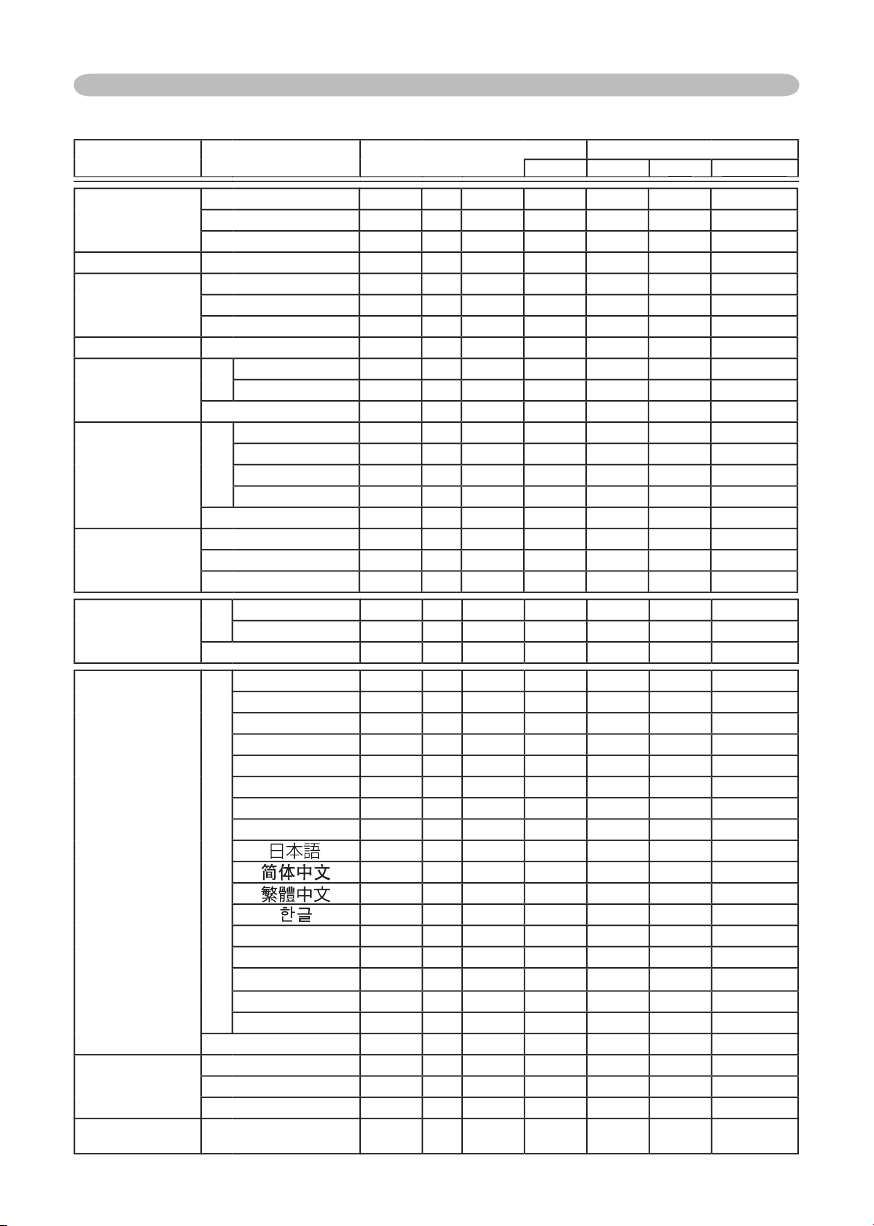
11
Technical (continued)
Command table (continued)
Names
Operation Type
Header
Command Data
CRC
Action
Type
Type
Type
Setting Code
Setting Code
Setting Code
ZOOM
Get
BE EF
03
06 00
D0 D0
02 00
0A 30
00 00
Increment
BE EF
03
06 00
B6 D0
04 00
0A 30
00 00
Decrement
BE EF
03
06 00
67 D1
05 00
0A 30
00 00
ZOOM Reset
Execute
BE EF
03
06 00
98 C9
06 00
70 70
00 00
KEYSTONE V
Get
BE EF
03
06 00
B9 D3
02 00
07 20
00 00
Increment
BE EF
03
06 00
DF D3
04 00
07 20
00 00
Decrement
BE EF
03
06 00
0E D2
05 00
07 20
00 00
KEYSTONE V Reset
Execute
BE EF
03
06 00
08 D0
06 00
0C 70
00 00
WHISPER
Set
NORMAL
BE EF
03
06 00
3B 23
01 00
00 33
00 00
WHISPER
BE EF
03
06 00
AB 22
01 00
00 33
01 00
Get
BE EF
03
06 00
08 23
02 00
00 33
00 00
MIRROR
Set
NORMAL
BE EF
03
06 00
C7 D2
01 00
01 30
00 00
H:INVERT
BE EF
03
06 00
57 D3
01 00
01 30
01 00
V:INVERT
BE EF
03
06 00
A7 D3
01 00
01 30
02 00
H&V:INVERT
BE EF
03
06 00
37 D2
01 00
01 30
03 00
Get
BE EF
03
06 00
F4 D2
02 00
01 30
00 00
VOLUME
Get
BE EF
03
06 00
31 D3
02 00
01 20
00 00
Increment
BE EF
03
06 00
57 D3
04 00
01 20
00 00
Decrement
BE EF
03
06 00
86 D2
05 00
01 20
00 00
MUTE
Set
TURN OFF
BE EF
03
06 00
46 D3
01 00
02 20
00 00
TURN ON
BE EF
03
06 00
D6 D2
01 00
02 20
01 00
Get
BE EF
03
06 00
75 D3
02 00
02 20
00 00
LANGUAGE
Set
ENGLISH
BE EF
03
06 00
F7 D3
01 00
05 30
00 00
FRANÇAIS
BE EF
03
06 00
67 D2
01 00
05 30
01 00
DEUTSCH
BE EF
03
06 00
97 D2
01 00
05 30
02 00
ESPAÑOL
BE EF
03
06 00
07 D3
01 00
05 30
03 00
ITALIANO
BE EF
03
06 00
37 D1
01 00
05 30
04 00
NORSK
BE EF
03
06 00
A7 D0
01 00
05 30
05 00
NEDERLANDS
BE EF
03
06 00
57 D0
01 00
05 30
06 00
PORTUGUÊS
BE EF
03
06 00
C7 D1
01 00
05 30
07 00
BE EF
03
06 00
37 D4
01 00
05 30
08 00
BE EF
03
06 00
A7 D5
01 00
05 30
09 00
BE EF
03
06 00
37 DE
01 00
05 30
10 00
BE EF
03
06 00
57 D5
01 00
05 30
0A 00
SVENSKA
BE EF
03
06 00
C7 D4
01 00
05 30
0B 00
PУCCKИЙ
BE EF
03
06 00
F7 D6
01 00
05 30
0C 00
SUOMI
BE EF
03
06 00
67 D7
01 00
05 30
0D 00
POLSKI
BE EF
03
06 00
97 D7
01 00
05 30
0E 00
TÜRKÇE
BE EF
03
06 00
07 D6
01 00
05 30
0F 00
Get
BE EF
03
06 00
C4 D3
02 00
05 30
00 00
MENU POSITION H
Get
BE EF
03
06 00
04 D7
02 00
15 30
00 00
Increment
BE EF
03
06 00
62 D7
04 00
15 30
00 00
Decrement
BE EF
03
06 00
B3 D6
05 00
15 30
00 00
MENU POSITION H
Reset
Execute
BE EF
03
06 00
DC C6
06 00
43 70
00 00
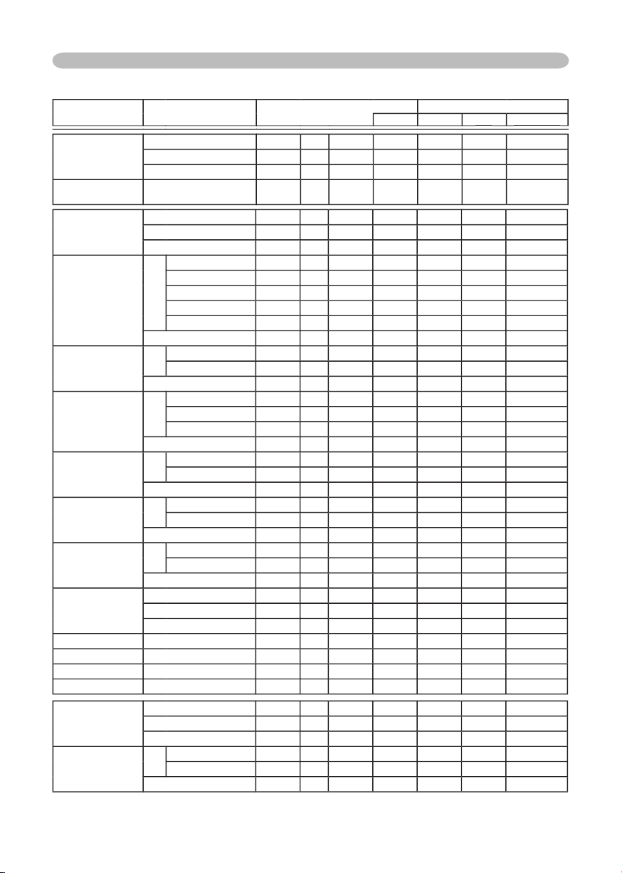
12
Technical (continued)
Command table (continued)
Names
Operation Type
Header
Command Data
CRC
Action
Type
Type
Type
Setting Code
Setting Code
Setting Code
MENU POSITION V
Get
BE EF
03
06 00
40 D7
02 00
16 30
00 00
Increment
BE EF
03
06 00
26 D7
04 00
16 30
00 00
Decrement
BE EF
03
06 00
F7 D6
05 00
16 30
00 00
MENU POSITION V
Reset
Execute
BE EF
03
06 00
A8 C7
06 00
44 70
00 00
OSD BRIGHT
Get
BE EF
03
06 00
A8 D5
02 00
18 30
00 00
Increment
BE EF
03
06 00
CE D5
04 00
18 30
00 00
Decrement
BE EF
03
06 00
1F D4
05 00
18 30
00 00
BLANK
Set
My Screen
BE EF
03
06 00
FB CA
01 00
00 30
20 00
ORIGINAL
BE EF
03
06 00
FB E2
01 00
00 30
40 00
BLUE
BE EF
03
06 00
CB D3
01 00
00 30
03 00
WHITE
BE EF
03
06 00
6B D0
01 00
00 30
05 00
BLACK
BE EF
03
06 00
9B D0
01 00
00 30
06 00
Get
BE EF
03
06 00
08 D3
02 00
00 30
00 00
BLANK On/Off
Set
TURN OFF
BE EF
03
06 00
FB D8
01 00
20 30
00 00
TURN ON
BE EF
03
06 00
6B D9
01 00
20 30
01 00
Get
BE EF
03
06 00
C8 D8
02 00
20 30
00 00
START UP
Set
My Screen
BE EF
03
06 00
CB CB
01 00
04 30
20 00
ORIGINAL
BE EF
03
06 00
0B D2
01 00
04 30
00 00
TURN OFF
BE EF
03
06 00
9B D3
01 00
04 30
01 00
Get
BE EF
03
06 00
38 D2
02 00
04 30
00 00
My Screen LOCK
Set
TURN OFF
BE EF
03
06 00
3B EF
01 00
C0 30
00 00
TURN ON
BE EF
03
06 00
AB EE
01 00
C0 30
01 00
Get
BE EF
03
06 00
08 EF
02 00
C0 30
00 00
Message
Set
TURN OFF
BE EF
03
06 00
8F D6
01 00
17 30
00 00
TURN ON
BE EF
03
06 00
1F D7
01 00
17 30
01 00
Get
BE EF
03
06 00
BC D6
02 00
17 30
00 00
AUTO SEARCH
Set
TURN OFF
BE EF
03
06 00
B6 D6
01 00
16 20
00 00
TURN ON
BE EF
03
06 00
26 D7
01 00
16 20
01 00
Get
BE EF
03
06 00
85 D6
02 00
16 20
00 00
AUTO POWER OFF
Get
BE EF
03
06 00
08 86
02 00
10 31
00 00
Increment
BE EF
03
06 00
6E 86
04 00
10 31
00 00
Decrement
BE EF
03
06 00
BF 87
05 00
10 31
00 00
LAMP TIME
Get
BE EF
03
06 00
C2 FF
02 00
90 10
00 00
LAMP TIME Reset
Execute
BE EF
03
06 00
58 DC
06 00
30 70
00 00
FILTER TIME
Get
BE EF
03
06 00
C2 F0
02 00
A0 10
00 00
FILER TIME Reset
Execute
BE EF
03
06 00
98 C6
06 00
40 70
00 00
MAGNIFY
Get
BE EF
03
06 00
7C D2
02 00
07 30
00 00
Increment
BE EF
03
06 00
1A D2
04 00
07 30
00 00
Decrement
BE EF
03
06 00
CB D3
05 00
07 30
00 00
FREEZE
Set
NORMAL
BE EF
03
06 00
83 D2
01 00
02 30
00 00
FREEZE
BE EF
03
06 00
13 D3
01 00
02 30
01 00
Get
BE EF
03
06 00
B0 D2
02 00
02 30
00 00

Hitachi, Ltd. Tokyo, Japan
International Sales Division
THE HITACHI ATAGO BUILDING,
No. 15 –12 Nishi Shinbashi, 2 – Chome,
Minato – Ku, Tokyo 105-8430, Japan.
Tel: 03 35022111
HITACHI EUROPE LTD,
Whitebrook Park
Lower Cookham Road
Maidenhead
Berkshire
SL6 8YA
UNITED KINGDOM
Tel: 01628 643000
Fax: 01628 643400
Email: consumer-service@hitachi-eu.com
HITACHI EUROPE S.A.
364 Kifissias Ave. & 1, Delfon Str.
152 33 Chalandri
Athens
GREECE
Tel: 1-6837200
Fax: 1-6835964
Email: service.hellas@hitachi-eu.com
HITACHI EUROPE GmbH
Munich Office
Dornacher Strasse 3
D-85622 Feldkirchen bei München
GERMANY
Tel: +49-89-991 80-0
Fax: +49-89-991 80-224
Hotline: +49-180-551 25 51 (12ct/min)
Email: HSE-DUS.service@hitachi-eu.com
HITACHI EUROPE S.A.
Gran Via Carlos III, 86, planta 5
Edificios Trade - Torre Este
08028 Barcelona
SPAIN
Tel: +34 93 409 2550
Fax: +34 93 491 3513
Email: atencion.cliente@hitachi-eu.com
HITACHI EUROPE srl
Via Tommaso Gulli N.39, 20147
Milano, Italia
ITALY
Tel: +39 02 487861
Tel: +39 02 38073415 Servizio Clienti
Fax: +39 02 48786381/2
Email: customerservice.italy@hitachi-eu.com
HITACHI Europe AB
Box 77 S-164 94 Kista
SWEDEN
Tel: +46 (0) 8 562 711 00
Fax: +46 (0) 8 562 711 13
Email: csgswe@hitachi-eu.com
HITACHI EUROPE S.A.S
Lyon Office
B.P. 45, 69671 BRON CEDEX
FRANCE
Tel: +33 04 72 14 29 70
Fax: +33 04 72 14 29 99
Email: france.consommateur@hitachi-eu.com
HITACHI EUROPE LTD (Norway) AB
STRANDVEIEN 18
1366 Lysaker
NORWAY
Tel: 67 5190 30
Fax: 67 5190 32
Email: csgnor@hitachi-eu.com
HITACH EUROPE AB
Egebækgård
Egebækvej 98
DK-2850 Nærum
DENMARK
Tel: +45 43 43 6050
Fax: +45 43 60 51
Email: csgnor@hitachi-eu.com
HITACHI EUROPE AB
Neopoli / Niemenkatu 73
FIN-15140 Lahti
FINLAND
Tel : +358 3 8858 271
Fax: +358 3 8858 272
Email: csgnor@hitachi-eu.com
Hitachi Europe Ltd
Bergensesteenweg 421
1600 Sint-Pieters-Leeuw
BELGIUM
Tel: +32 2 363 99 01
Fax: +32 2 363 99 00
Email: sofie.van.bom@hitachi-eu.com
HITACHI EUROPE LTD
Na Sychrove 975/8
101 27 Pr aha 10 – Bohdalec
CZECH REPUBLIC
Tel: +420 267 212 383
Fax: +420 267 212 385
Email: csgnor@hitachi-eu.com
www.hitachidigitalmedia.com

