Loading ...
Loading ...
Loading ...
WARNING – SERVICING TO BE CARRIED OUT ONLY BY AN AUTHORISED PERSON
Disconnect from electricity and gas supplies before servicing. Check appliance is safe when you have nished.
40
5 Ovens
5.1 To Replace an Oven Thermostat
n
DISCONNECT FROM THE ELECTRICITY SUPPLY.
Remove the handrail (see 1.1), control panel (see 1.2) and
hotplate top (see 2.1). Open the oven doors and remove the
oven furniture.
Left-hand oven
From inside the oven remove the two screws holding the
thermostat phial to the oven fan cover at the rear of the oven.
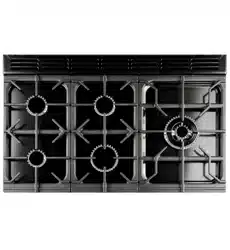
Remove the four screws that secure the fan cover
(Fig. 12.5) then remove the fan cover.
Pull cooker forward to gain access to the cover box at the rear
of the cooker. Remove the screws securing the cover and lift
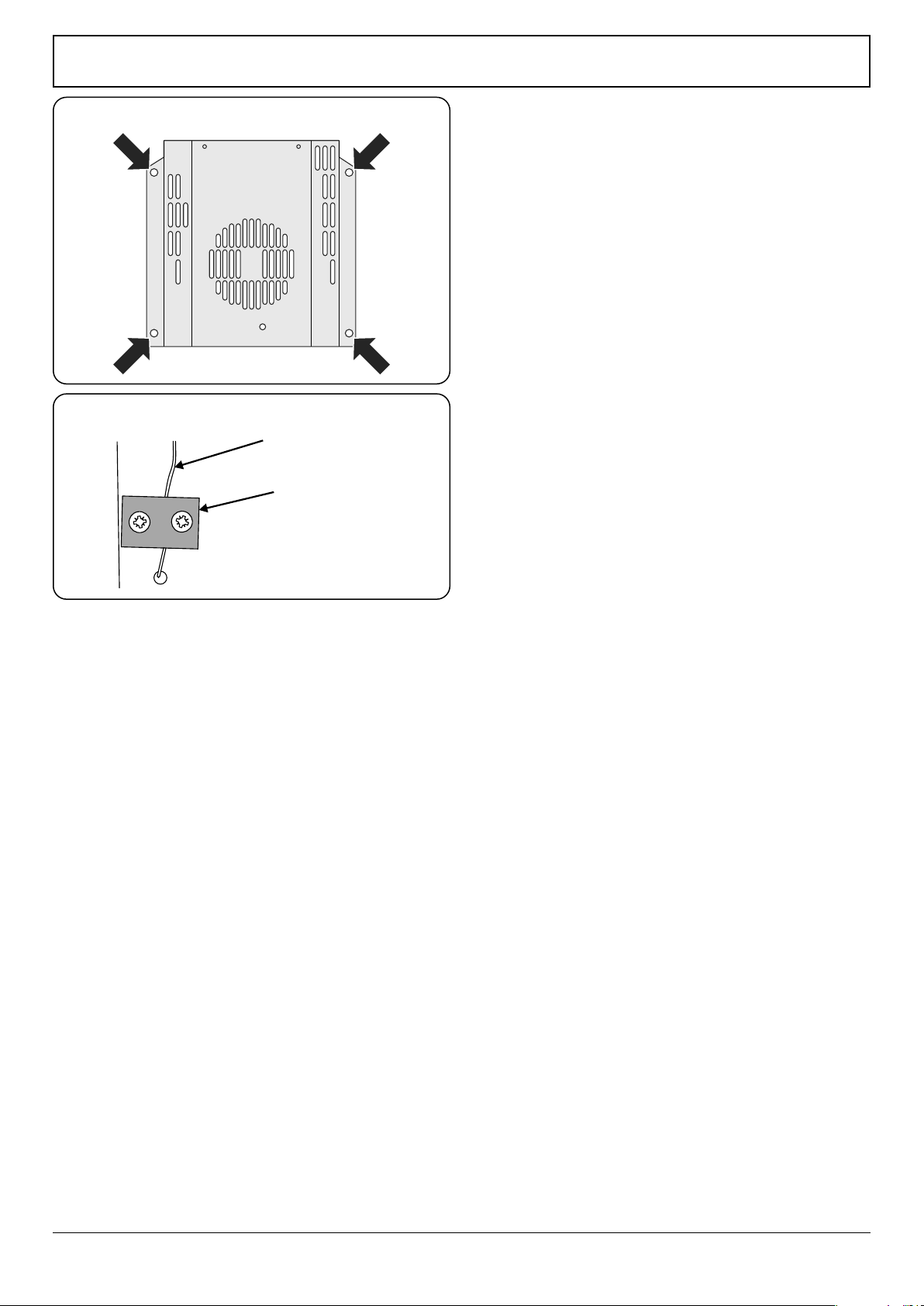
clear. The oven thermostat capillary is clamped to the oven
back sheet with an earthing plate. Remove the screws and
plate (Fig. 12.6).
Remove the two screws securing the thermostat body to
the control panel at the front of the cooker. Remove the
assembly.
Fit new thermostat. Reassemble in reverse order.
Ensure that the phial is clipped to the oven back with the
phial centrally positioned between the clips.
Ensure that the thermostat capillary is clamped to the oven
back sheet with an earthing plate.
Check operation of thermostat.
Right-hand oven
Remove the oven inner back xing screws and remove the
inner back. Unclip the thermostat phial from the clips on the
oven back. From the top pull the thermostat capillary up and
out. Disconnect the leads and remove the thermostat and
phial. Reassemble in reverse order.
Check the operation of thermostat.
5.2 To Remove an Oven Element Thermal Cut-out
n
DISCONNECT FROM THE ELECTRICITY SUPPLY.
Pull the cooker forward to gain access to the cover box. Undo
the cover screws and lift clear. The cut-out is located on the
earth plate beside the oven element connections. Disconnect
the cut-out wiring. Undo the xings that secure the cut-out to
the earth plate and remove.
Fit the replacement control and reassemble in reverse order.
Thermostat capilary
Earthing plate
Fig. 12.6
Fig. 12.5
Loading ...
Loading ...
Loading ...