
EP500Pro Power Station
Please read this manual before use and follow its guidance. Keep this manual for future reference.
User Manual
Please read this manual before use and follow its guidance. Keep this manual for future reference.

Contents
01. EP500Pro Introduction ............................. 01
02. General Safety Instructions ...................... 02
03. What`s in the Box .................................. 05
04. APP........................................................ 07
05. Features of EP500Pro .............................. 11
06. Startup & Power off ................................. 12
07. User Interface ....................................... 13
08. How to Recharge EP500Pro (INPUT) ...........20
09. Discharge (OUTPUT) ............................... 27
10. UPS ...................................................... 30
11. Split Phase Function ................................ 35
12. Technical Specification ............................ 38
13. Storage and Maintenance ......................... 40
14. Troubleshooting ..................................... 41
15. FAQ (Frequently Asked Questions) ............ 46
16. Declaration ............................................ 48
01
Just Power On
01. EP500Pro Introduction
1.1. Introduction
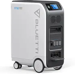
●BLUETTI is proud to take the energy storage world by storm with the release of
its rst home energy storage system series - the EP500Pro with four smooth-
rolling transport wheels, the EP500Pro was not designed to be a large solar
battery mounted on the wall or in the garage. The BLUETTI EP500Pro was not
only designed to be a "No Installation Needed", plug-and-play mobile UPS that
can easily be moved to the desired location when necessary, but also a power
backup system that ensures emergency power when a power outage occurs.
●The EP500Pro system uses a dual-core controller (ARM controller + DSP controller)
which combines digital and analog signals perfectly to manage and control the MPPT
module, the AC Inverter module (Bidirectional topology, supporting AC reverse fast
charging), the DC-to-DC module, and the built-in battery pack.
●EP500Pro integrates a solar charge controller, AC charge controller, AC inverter,
lithium battery, and battery management system into one, converts clean and
environmentally friendly solar energy and grid electricity into clean power sent to
all of your home appliances.
● EP500Pro Power Station system is suitable for areas with energy shortage or
unstable power, and also for the power supply or disaster emergency in areas
without stable power supply such as isolated islands and borders.
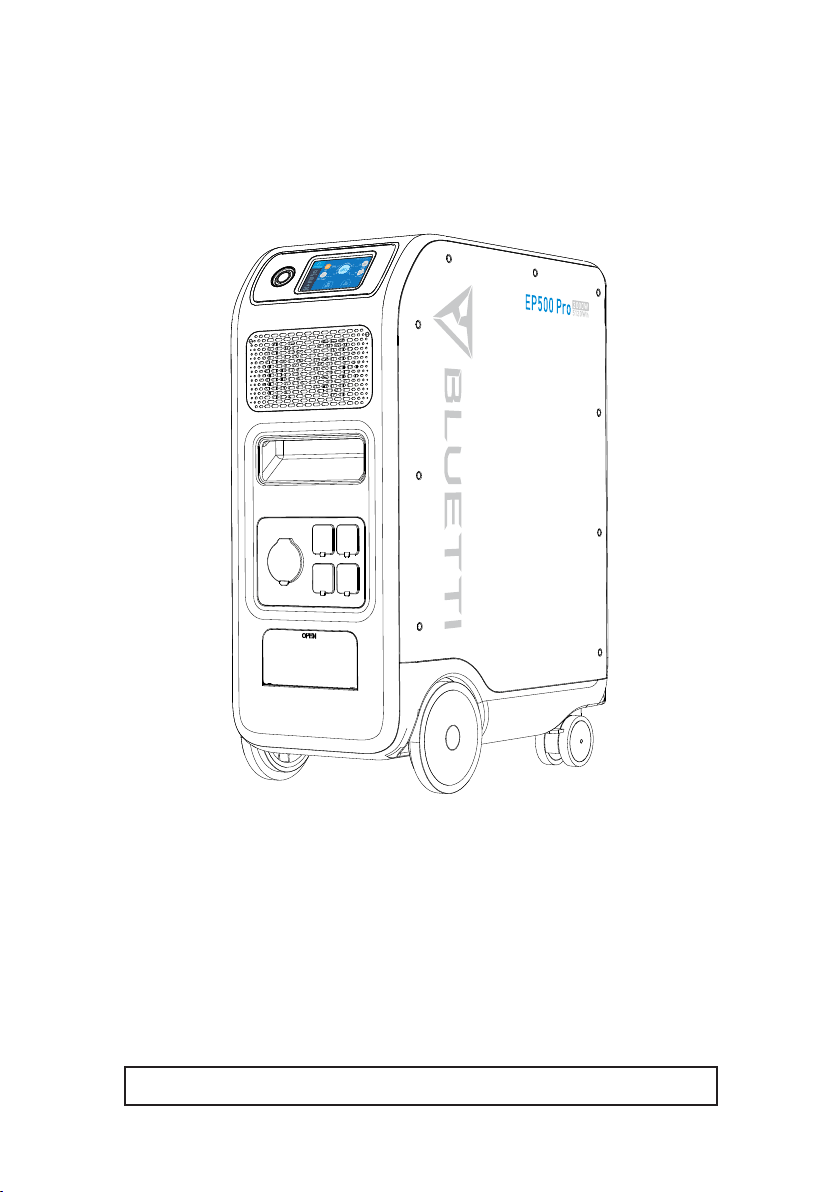
( EP500Pro grid-tie home
power back-up system )

02
BLUETTI
1.2. Abbreviation
● BMS: Battery Management System
● MPPT: Max. Power Point Tracking
● SOC: State of Charge
● UPS: Uninterruptible Power Supply
● AC: Alternating Current
● DC: Direct Current
● PV: Solar Panel(s) Charging(Photovoltaic)
● Grid: Home Power Supplied by Utility
● T500: 500W additional charger
● DOD: Depth of Discharge
● ECO Mode: A power - saving mode for the EP500Pro, the AC output ports are
automatically turned off if the load is less than 30W over a span of 4 hours.
02. General Safety Instructions
Please read this manual before operating.
● A licensed electrician is required to install the grid-tie power system as
involves connecting the wires of critical equipment from your main electrical
box to the BLUETTI Sub Panel (Optional Purchase).
● DO NOT place EP500Pro near heat sources. It is prohibited to place and operate
EP500Pro in an environment with ammable, explosive gas,or smoke.
● DO NOT attempt to replace the internal battery or any other components of
EP500Pro by anyone other than authorized personnel. There are no user-
serviceable components in the package.
● DO NOT operate in wet conditions. If EP500Pro becomes wet, please let the
unit dry completely before using.
● Please ensure proper ventilation while in use and do not obstruct fan openings.
Inadequate ventilation may cause permanent damage to the equipment.
● DO NOT stack anything on top of the power station either in storage or while
in use.
● DO NOT move the unit while operating as vibrations and impacts may lead to
poor connectivity to hardware inside.

03
Just Power On
● Warning:
DO NOT insert foreign objects into any ports of EP500Pro (both AC & DC &
ventilation holes). EP500Pro generates the same potentially lethal AC power
as a household wall outlet. Please use EP500Pro carefully and keep children
away from it.
● If necessary, only the dry powder re extinguisher is suitable for the product.
● For safety purposes, please use only the original charger and cables designed
for the equipment. We are not liable for damage caused by third-party
equipment and may render your warranty, invalid.
2.1. Installation (for grid-tie system)
● Before touching any conductor surface or terminal, measure the voltage of
the contact point to conrm that there is no danger of electric shock.
● After the equipment is installed, empty packaging materials such as cartons,
foam, plastic, cable ties, etc. should be removed from the equipment area.
● Except for those who operate the equipment, please keep others away from
the equipment.
● The handling of any tools being used needs to be insulated and protected
from shock, or use insulated tools.
● All wiring holes need to be sealed. Use re-resistant mud to seal the wiring
holes that have been routed and use the cover of the cabinet.
● It is strictly forbidden to alter, damage or obscure the logo and nameplate on
the equipment.
● When installing the device, please use the appropriate tools to tighten any
screws.
● Live operation is strictly prohibited during installation.
● Before operation, the equipment should be secured onto a oor or other
stable objects, such as walls or possibly mounting brackets if needed.
● It is prohibited to clean any electrical components inside and outside the
cabinet with water.
● Do not change or modify the structure, installation sequence, etc. of the
equipment without prior authorization.
2.1.1. Personal Safety
● The personnel responsible for the installation and maintenance of the equipment
must first undergo rigorous training to understand various safety precautions

04
BLUETTI
and grasp the correct method of operation.
● Trained personnel: personnel who have undergone corresponding technical
training and have the necessary experience to be aware of the danger that may
be brought to him during the operation, and can take measures to reduce the
danger to himself or other personnel to at the lowest limit.
● The replacement of equipment or parts (including software) must be done by
professionals or authorized personnel.
2.1.2. Personnel Requirements
● The personnel responsible for the installation and maintenance of the
equipment must rst undergo rigorous training to understand various safety
precautions and grasp the correct method of operation.
● Trained personnel: personnel who have undergone corresponding technical
training and have the necessary experience to be aware of the danger that
may be brought to him during the operation, and can take measures to
reduce the danger to himself or other personnel to at the lowest limit.
● The replacement of equipment or parts must be done by professionals or
authorized personnel.
2.1.3. Anti-static requirements
When installing the sub-panel with your main panel, you must wear anti-static
gloves or an anti-static wrist strap before touching the device. The other end of
the anti-static wrist strap should be properly grounded. Do not touch any bare
components directly with your hands.
2.1.4. Drilling
The following safety precautions are to be considered when drilling holes on the
wall or into the ground:
● It is strictly forbidden to drill holes into the equipment. Drilling will alter and
damage the electromagnetic shielding performance of the equipment, internal
components, and cables. The risk of metal shavings entering the device can
cause short circuits on the circuit board.
● Wear goggles and protective gloves when drilling holes.
● The equipment should be shielded and protected during the drilling process
to prevent debris from falling into the equipment. After drilling, any debris
which may have landed on the equipment should be removed and cleaned.
05
Just Power On
2.2. Installation environment requirements
● When the equipment is running, please do not block the vents or the heat
dissipation system in order to prevent high temperatures and/or fires.
● The equipment should be installed in an area away from liquids. It is forbidden
to install it near or below water pipes, air outlets and other locations that are
prone to water condensation.
● It is forbidden to install the unit underneath pipes, windows or other similar
areas that are prone to water leaks in order to prevent liquids from entering into
the equipment. Failure to do so may result in a short circuit.
● If liquid is found inside the device, user must turn off the power immediately.
● The equipment room must be properly insulated and the walls and floors must
be damp-proof.
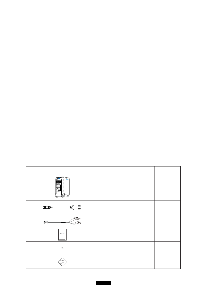
03. What`s in the Box
Standard Accessories
No. Picture Category Quantity
1
EP500Pro Power Station 1
2
AC Charging Cable
Charging EP500Pro via wall outlet
1
3
PV Charging Cable
Charging EP500Pro via solar power
1
4
EP500Pro POWER STATION
Please read this manual before use and follow its guidance. Keep this manual for future reference.
User Manual
Please keep it for future reference
1
5
Warranty Card
For after-sale service
1
6
Certicate of QC PASS 1
06
BLUETTI
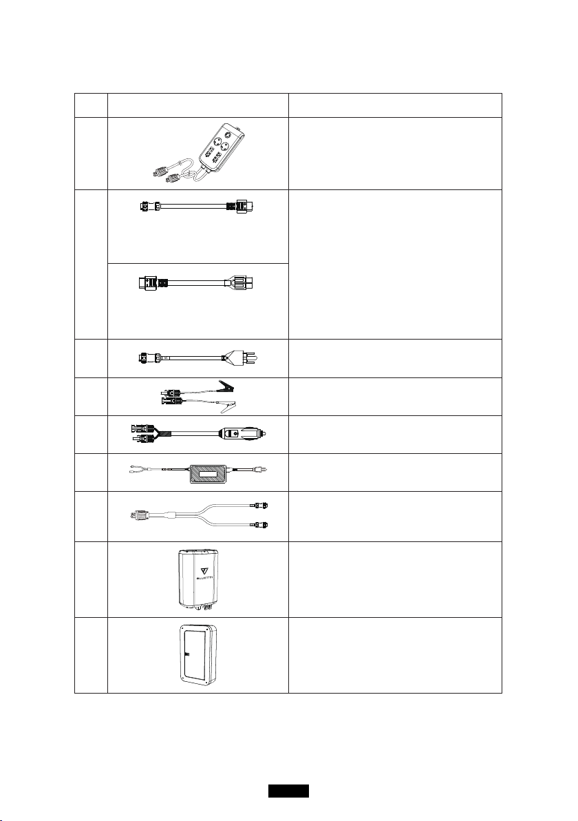
Additional Purchase Accessories
Sold on BLUETTIPOWER.COM
No. Picture Category
7
Split Phase Box Pro (P030A)
To double the capacity, power of output
and voltage.
8
12V/30A XT60 to
Aviation Plug
12V/30A RV Cable
For 30A DC Output.
XT60 to SPC45
To support DC power supply for RV.
9
Generator Charging Cable
Charging EP500Pro via generator.
10
Lead-acid Battery Charging Cable
Charging EP500Pro via Lead-acid battery.
11
Car Charging Cable
Charging EP500Pro with cable No3.
12
T500 500W Adapter
Additional 500W AC charger.
13
AC Charging Cable for Split Phase
Charging two EP500Pro connected in split
phase mode via wall outlet.
14
PV Drop Down Module(D300S)
Charge EP500Pro via roof/rigid panels.
15
Sub Panel
Integrate the power station to your home
circuit as backup UPS.
07
Just Power On
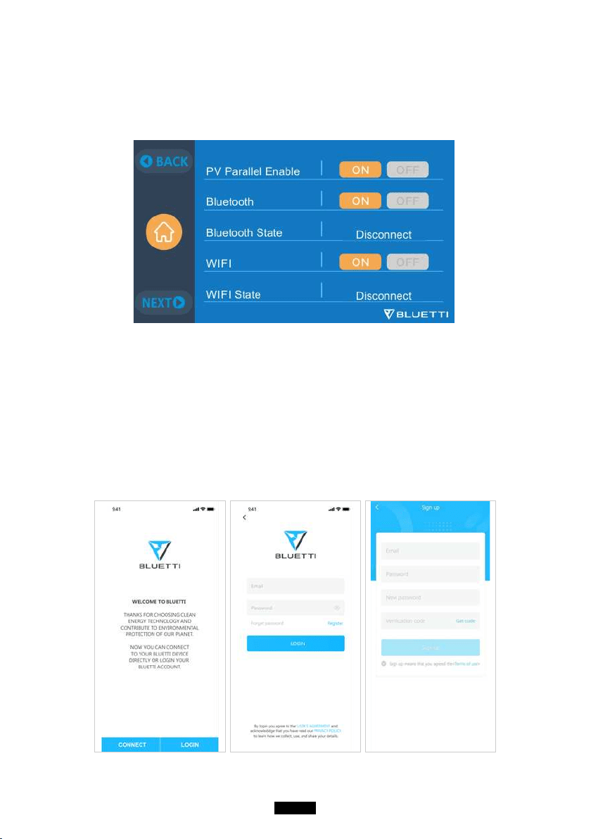
04. APP
Please make sure the state of Bluetooth & Wi-Fi settings is “ON” before
connecting EP500Pro with BLUETTI App.
(Homepage - Settings - Next - Next)
Step 1:
● Please search “BLUETTI” on the App Store (for IOS devices) or Google Play
(for Android devices) to download the BLUETTI App to remotely control your
EP500Pro.
● EP500Pro can be controlled via Bluetooth or Wi-Fi. To activate the remote
control, please launch the BLUETTI App,and click the “LOGIN” icon to “REGISTER”
your BLUETTI account and fill with your related information to continue.
08
BLUETTI
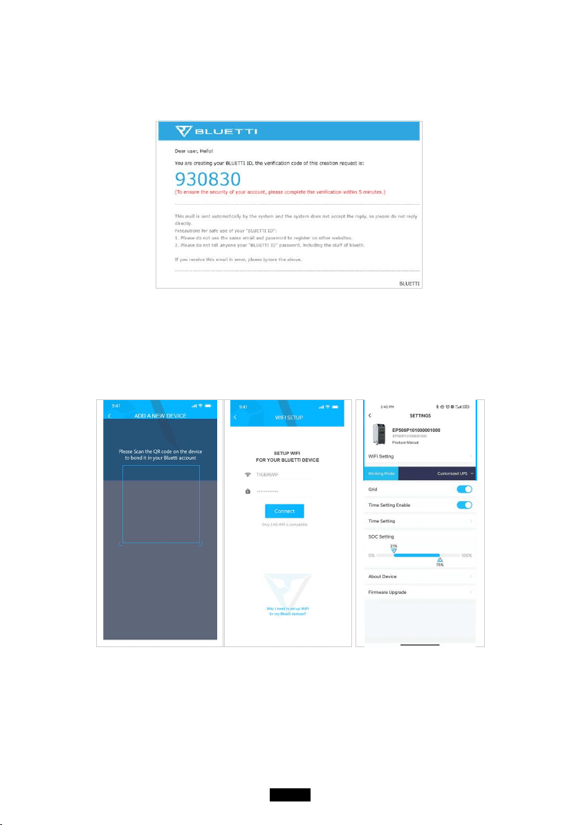
● Check your email account you used in the BLUETTI App for the verication
code sent from BLUETTI and ll in the activation code located within the
email to activate your BLUETTI account.
Step 2:
● Scan the unique QR code on EP500Pro to add the unit on the available device list
on the App, and fill it with the password of your 2.4G Wi-Fi network to activate
the communication function of EP500Pro for data syncing.
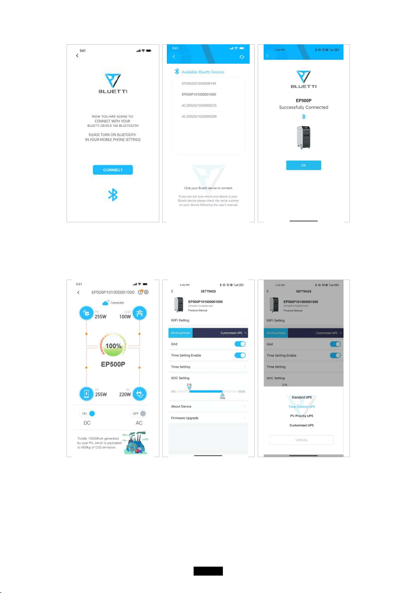
● For Bluetooth Connecting, tap ‘’CONNECT’’ at the homepage to connect
EP500Pro with your phone via Bluetooth, select the SN number of your devices.
Please press ‘’settings-product info’’ on EP500Pro to view the SN number of your
unit.
09
Just Power On
● The basic information can be viewed after the unit is connected with App successfully.
Press ‘’gear icon’’ to customize the current working mode and parameters of
your EP500Pro under “Settings”.
● The BLUETTI App supports a “Firmware Update” function which allows access to
the latest software upgrades for continued features, improvements and xes.

10
BLUETTI
Note: Please keep your phone 5m/16.4ft within the EP500Pro for a better
connection during update.
Also, if BLUETTI APP fails to connect to the Internet. Tap "Settings" at the
homepage of your phone and scroll down until the BLUETTI App shows
up(IOS). Tap "Settings" on homepage of your phone, tap “Application
Management” and select BLUETTI(Android). Tap the BLUETTI icon and
verify that "Wireless and Data" permissions are enabled.
User cannot turn on EP500Pro via BLUETTI App.
11
Just Power On
05. Features of EP500Pro
11
12
13
1
6
2
3
4
5
10
9
14
7 8
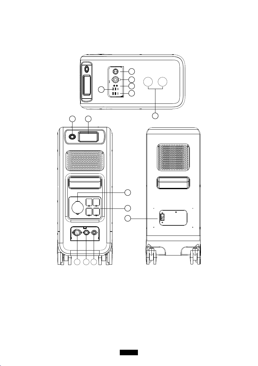
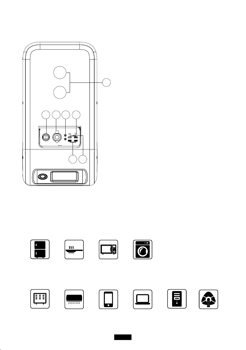
12V/30A Port
12V/10A Cigarette Lighter Port
12V/10A DC5521 Port
USB-C (PD3.0 protocol supported)
USB-A
Wireless Charging Pad
Power Button
Touchscreen
AC Output Port(30A MAX)
AC Output Port(20A MAX)
AC Input Port
DC1/DC2 Input Port
Communication Interface
Main Battery Switch
12
BLUETTI
06. Startup & Power o
( Back )
( Front )
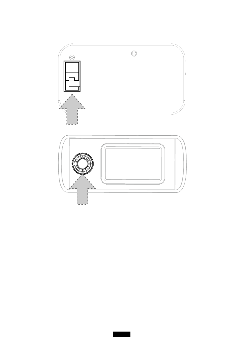
● Turn on the main power switch located on the back of EP500Pro.
● Power On: Long press the power button. The power button indicator will
illuminate.
● Power Off: Long press the power button. The power button indicator light will
turn off.
● EP500Pro will turn on automatically from Power Off status when either grid
charging and/or PV charging is applied on.
● DC and AC power switch are accessible on the Touchscreen. Press the “DC ON/
OFF” button and/or “AC ON/OFF” button to turn ON/OFF the DC/AC output.
13
Just Power On
07. User Interface
7.1. Main Interface
Tip:
The LCD resistive touchscreen, recommended to press lightly with the edge of
your fingernail until it "beeps" when it registers a press. (NOTE: Touchscreen
sounds can be disabled in the Settings menu).
e f g
k
l
ih j
a
b
c
d
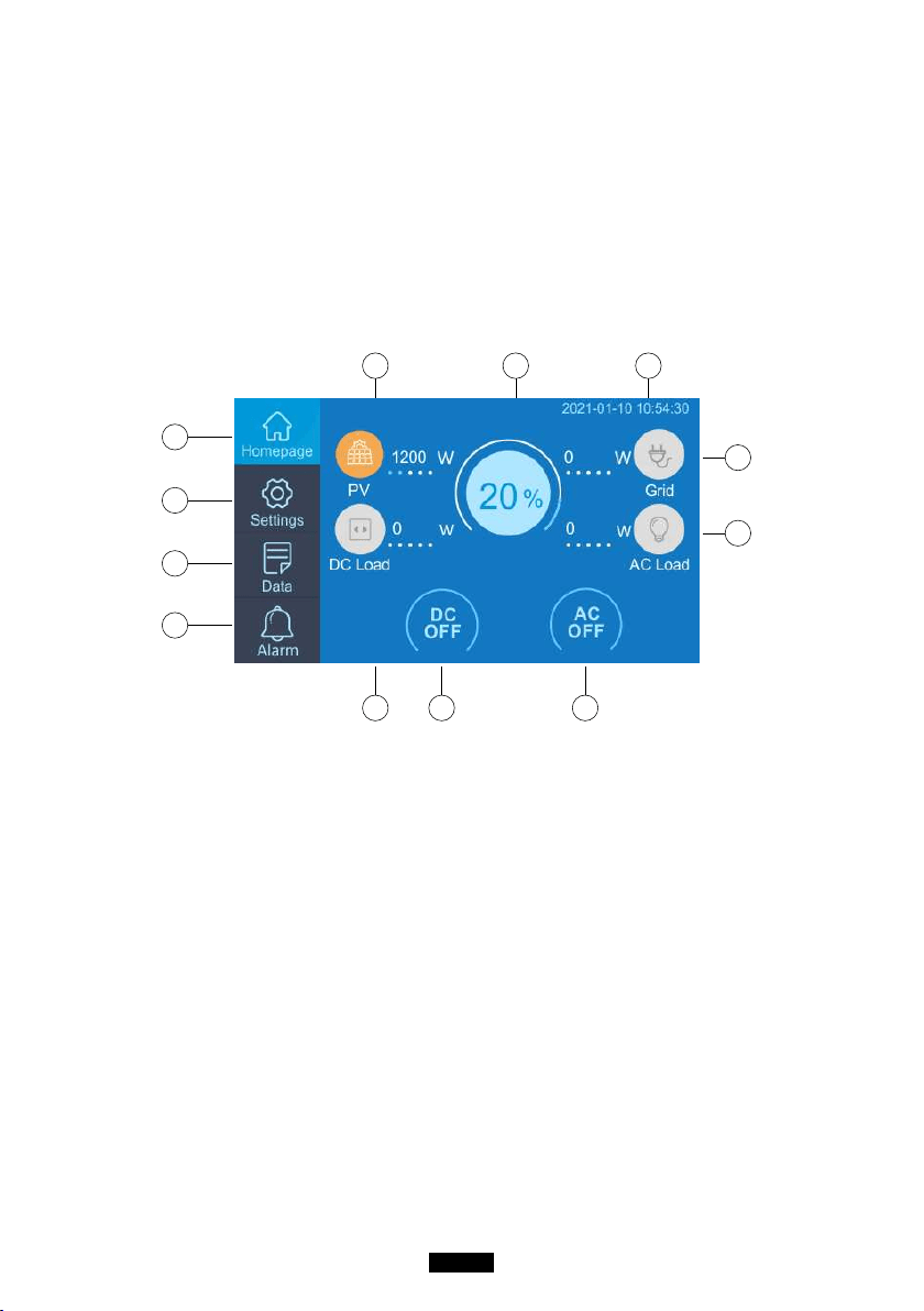
. Homepage
. Settings
. Data
. Alarm
. PV Charging Information
. BMS Information
. Date/Time
. DC load Information
. DC ON/OFF
. AC ON/OFF
. AC load Information
. AC Charging Information
a
b
c
d
e
f
g
h
i
j
k
l
7.2. Settings
●
User can customize the working mode of EP500Pro and tweak the
equipments parameters such as language, voltage, frequency, current (UPS
Grid -Tie Mode), working type, date/time, etc.
● Tap the Settings Button on the homepage to enter the setting interface.
14
BLUETTI
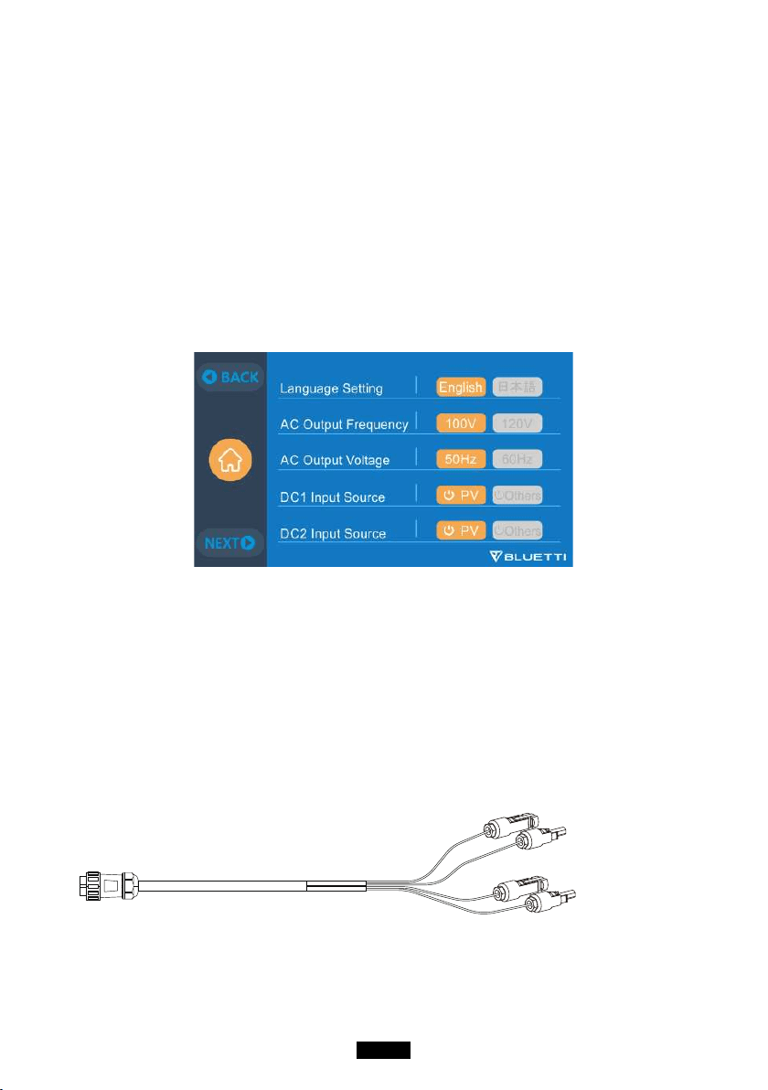
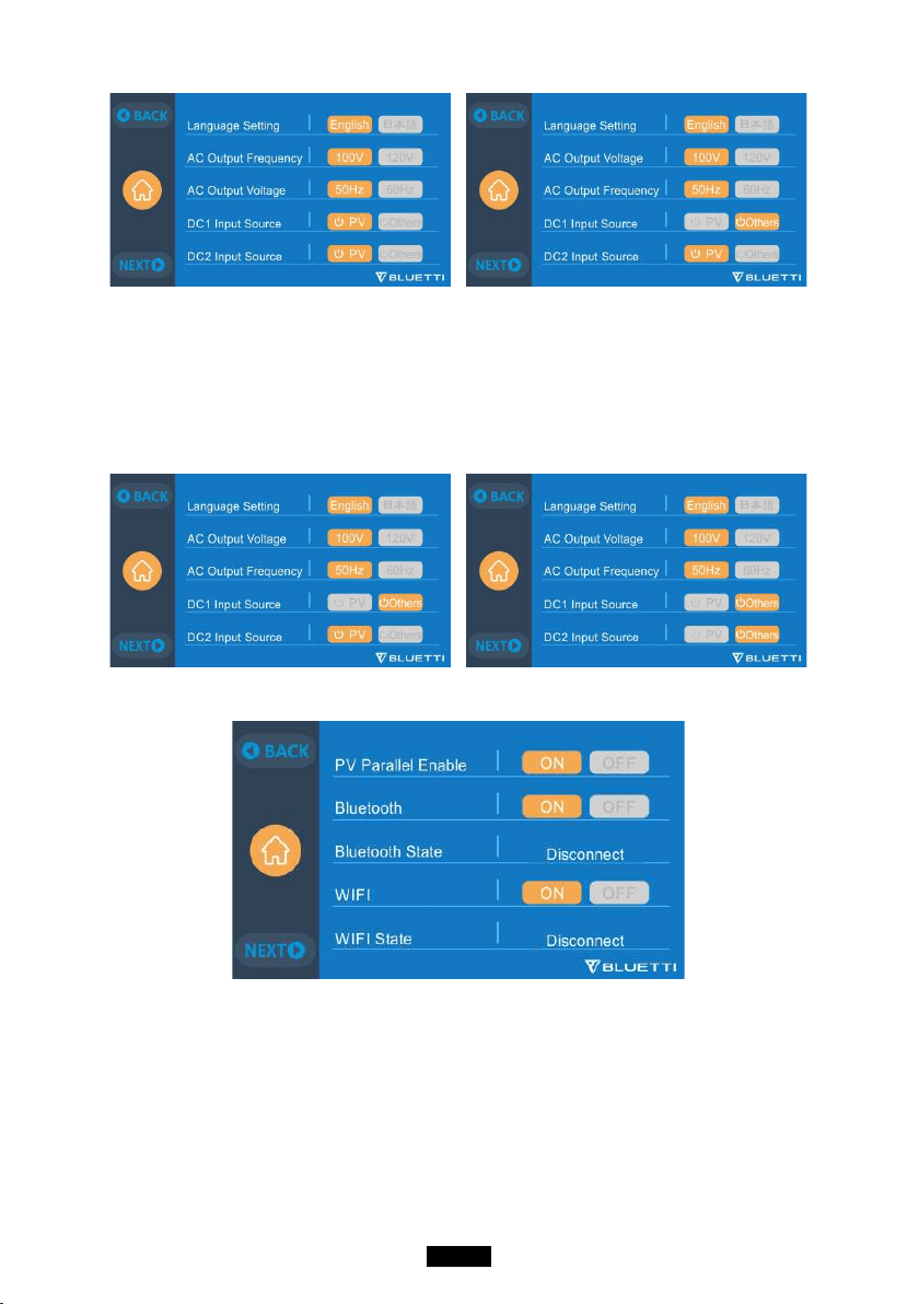
7.2.1. AC Output Voltage & Frequency
● NOTE: Please check the output voltage, frequency, and other parameters
BEFORE using EP500Pro for the first time. The EP500Pro 100-120V AC version
cannot be set to 220-240V AC output.
● The Output frequency and voltage can only be tweaked when the AC is OFF(tap
the AC icon at homepage to turn off AC output if it`s ON).
● The list of standard output voltage and frequency in 5 regions or countries. You
may tap on the screen to set the parameters as needed.
●JP Output: 100V/50Hz or 60Hz
●US Output: 120V/60Hz
●AU Output:240V/50Hz
●EU/UK Output: 230V/50Hz
7.2.2 DC Input Source
DC Input Source: EP500Pro integrates dual MPPT and separates the DC input
source into DC1 and DC2 in parallel. DC1 indicates the first group of DC input
source as the labels written on MC4 plug of PV charging cables:
DC1 PV+ and DC1 PV-, DC2 PV+ and DC2 PV-. DC1/DC2 consist of both positive
pole and negative pole of the MC4 plugs.
Both DC1 and DC2 input source can be set on touchscreen: (Homepage - Settings
- DC1/DC2 Input Source).
DC1 PV+/PV-
DC2 PV+/PV-
Can be set on screen:
(Homepage - Settings - DC1/DC2 Input Source)
15
Just Power On
1
2 3
4
1
2
2
3
3
4
1
a, Connect your solar panels in series into PV charging cable.
b, Plug the Aviation plug into the middle input port(CP2) on EP500Pro.
7.2.3. Language Setting & ECO Mode
Press “English” or “Japanese” icon to set as the default system language to be
displayed on your EP500Pro.
ECO: When ECO is turned ON, if the AC output load is less than 30W for 4
hours,the AC ports will be shut off for power-saving.
16
BLUETTI
7.2.4. Machine Type (for split phase setting, exclusive for 100-120V Version)
Please turn to Chapter11 for detailed installation.
7.2.5. Working Mode(Homepage - Settings - Next - Working Mode)
Tips: EP500Pro will be set as the Standard UPS Mode as default.
There are altogether four working modes you can select in settings:
Standard UPS Mode: Default working mode(Offline mode).
PV Priority Mode: Recommended for areas in stable power supply.
Time Control Mode: Suitable for areas with peak and off-peak time-of-use rates
for money saving.
Customized Mode: Customized the parameters for a better user experience.
Detailed UPS Mode setting please check Chapter 10 UPS.
17
Just Power On
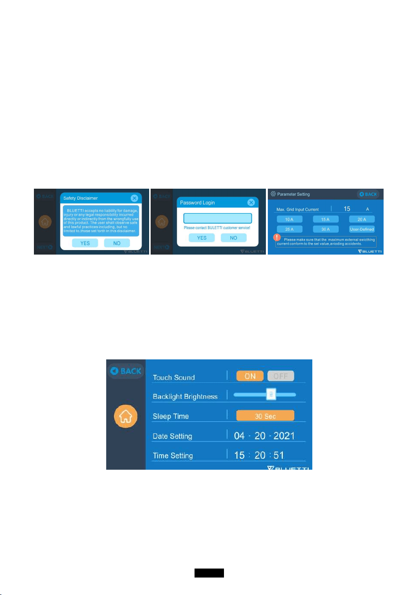
7.2.6. Max. Grid Input Current
● Please check the specication of your grid, sockets, connections, wires, etc. to
determine the maximum allowable current that can be drawn by the EP500Pro.
BLUETTI is not liable for any damages, injuries, or any other legal responsibility
incurred directly or indirectly from changes made to this setting.
● Max. Grid Input Current: limit the Max. current of the tied grid, when the
current exceeds the preset value, EP500Pro will take charge to be the power
source of the circuit.
Note: Only take eect when EP500Pro has been connected into grid.
The value is preset at 15A.
7.2.7. Date and time & Touch Sound & Backlight Brightness
● Tap each respective date and time setting in order to set the date and time
as applicable to your local time zone.
● Tap to Enable/Disable touch sounds.
● You may change the Backlight Brightness of the Touchscreen LCD by using
the slider on the screen.
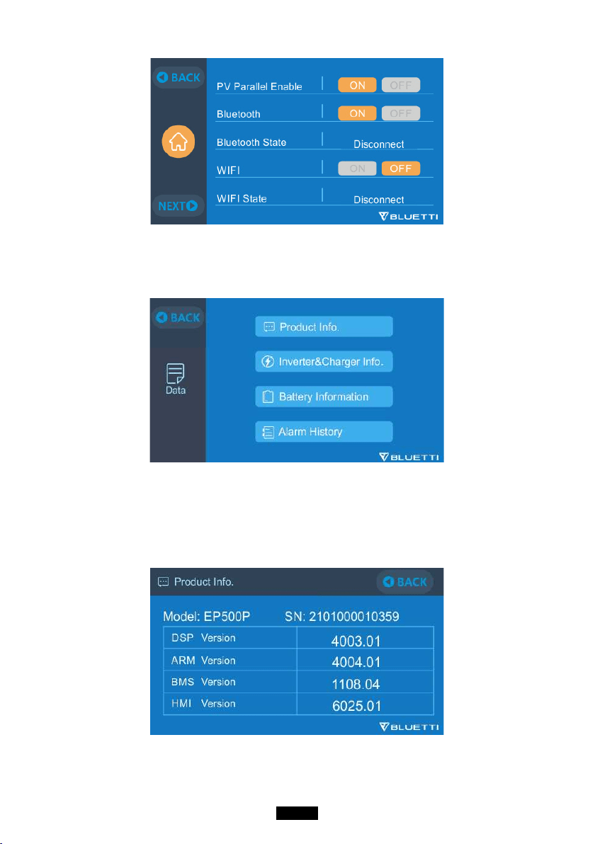
7.2.8. Bluetooth & Wi-Fi Connection
The Bluetooth and Wi-Fi connection can be turned ON or OFF by tapping the
ON and OFF icon for either function.
User cannot connect EP500Pro to BLUETTI App when both of the Wi-Fi and
Bluetooth function is disabled.
18
BLUETTI
7.3. Data
In the Data section, you may view Product Info, Inverter & Charger Info, BMS
Maintenance, and Alarm/Fault History by selecting each respective button.
7.3.1. Product Info
● When you select the “Product Info” button, you can view the product model,
serial number (SN), control software version, monitoring software version,
BMS monitoring software version and display software version.
● The Serial Number (SN) can also be used to pair to BLUETTI APP manually.
7.3.2. Inverter & Charger Info
By tapping the “Inverter & Charger Info” button, user can view the PV charging,
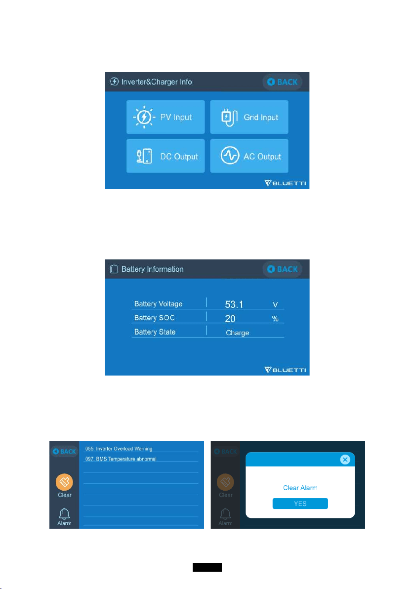
19
Just Power On
adapter charging, DC output and AC output working status. This section can also
be accessed directly from the shortcut icon on the homepage.
7.3.3. Battery Information
By tapping the “Battery Information” button, user can view the live information of
the status of the battery pack. This section can also be accessed directly from the
shortcut icon on the homepage.
7.3.4. Alarm History
Tap the “Alarm History” button, user can view all the alarm information generated
by the machine. User can turn to the Chapter 14 Troubleshooting to check the
corresponding solutions.
20
BLUETTI
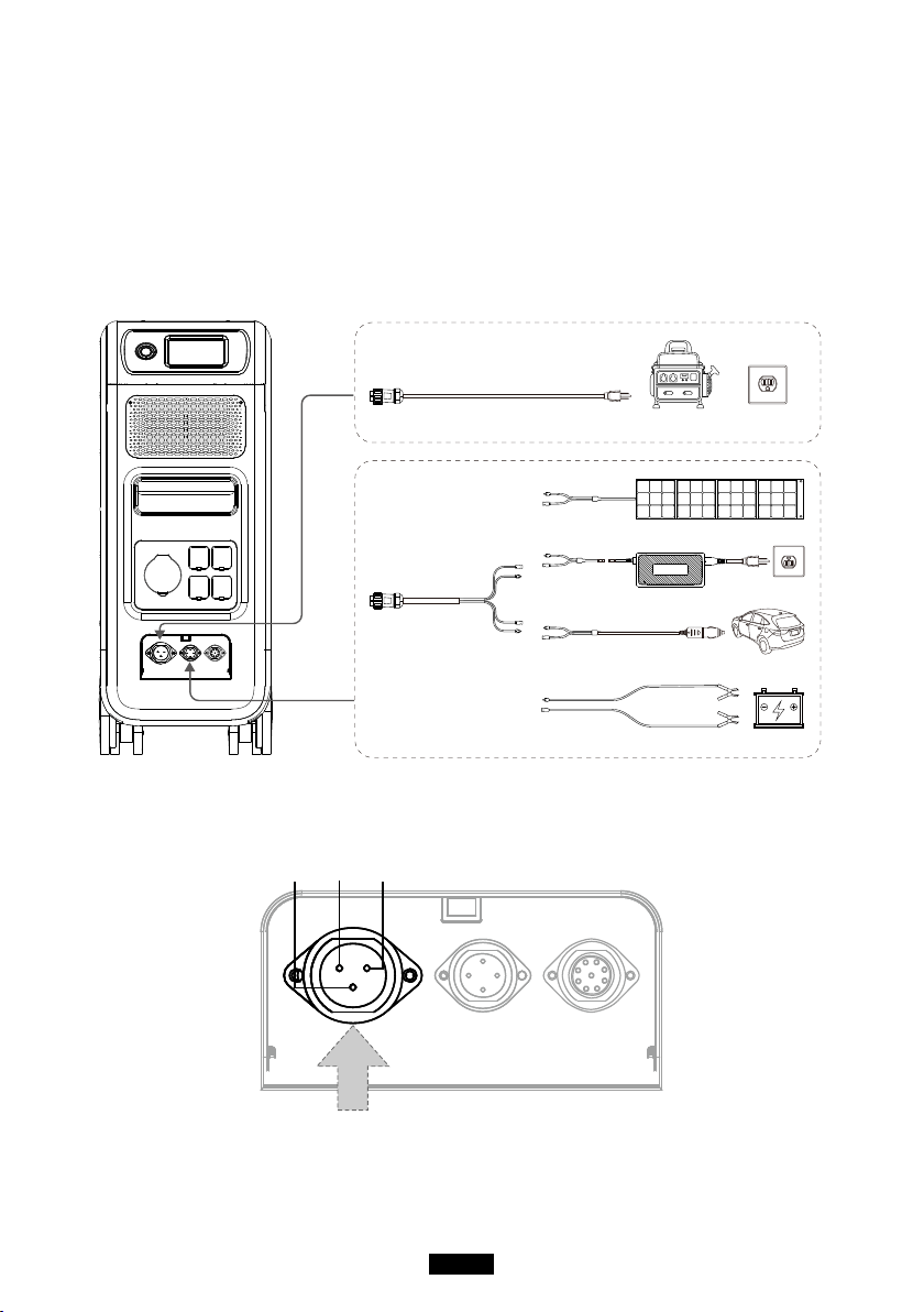
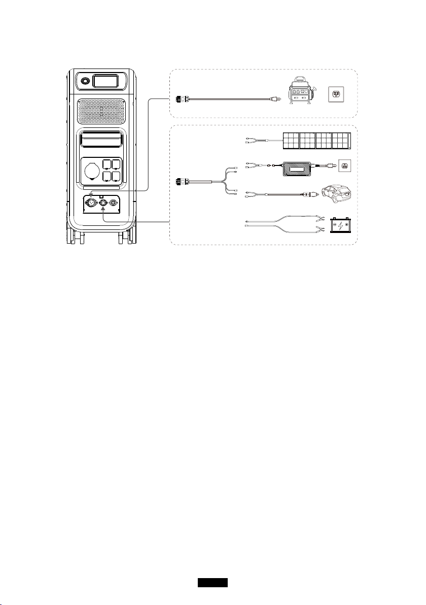
08. How to Recharge EP500Pro (INPUT)
● The EP500Pro includes two charging ports which can be recharged in different
methods. They will be covered in three different sections according to which
port(s) are being connected.
● The two ports are named as Aviation Charging Port 1 [CP1] and Aviation
Charging Port 2 [CP2].
Solar Panel
Second Adapter
Lead-acid Battery
Car
Wall OutletGenerator
Aviation
Port 2 (CP2)
Aviation Port 1 (CP1)
8.1. CP1 (1st Charging Port)
Pin1Pin2Pin3
Pin1:L
Pin2:N
Pin3:PE
8.1.1. Charging Method 1: From Wall Outlet (by AC charging cable)
Connect the EP500Pro from CP1 via the AC charging cable to the wall outlet
21
Just Power On
@1500W/100Vac , @1800W/120Vac Max .
The charging process will automatically stop when it reaches 100% capacity.
Additionally, you can choose to access the BLUETTI Sub Panel or the L14-30
receptacle, the maximum charging power allowed will be up to 3000W.
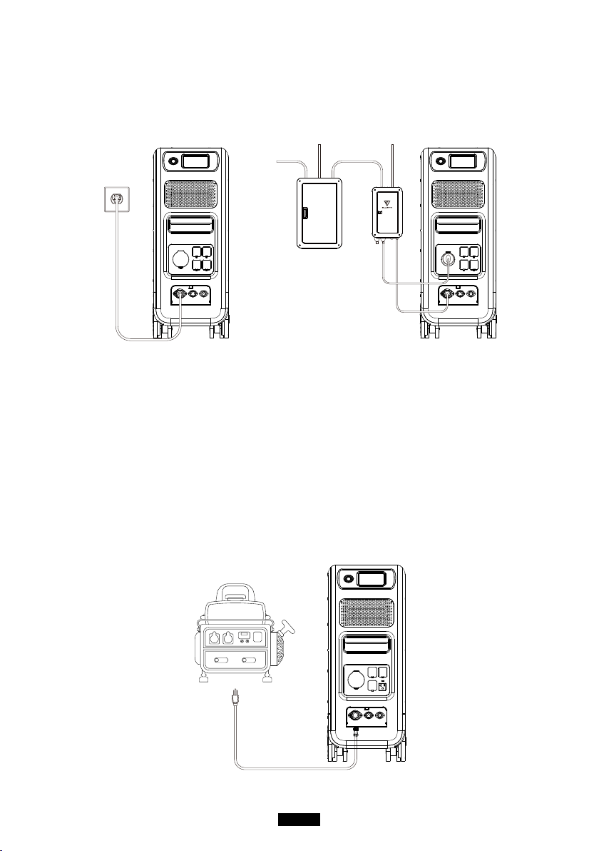
Charging via wall outlet
Charging via Sub Panel
Main
Panel
Sub
Panel
8.1.2. Charging Method 2: From Generator (gasoline, propane, or diesel)
● Connect the EP500Pro from CP1 via the generator charging cable (sold
spearately) to the AC output of the generator. The charging process will
automatically stop when it reaches 100%.
● The required output power of your generator has to exceed the Max. input
power of the AC input port of the EP500pro. Also a generator with a pure sine
wave output is recommended (e.g. Inverted-based Generators)
Voltage limit:
85-110VAC/JP(100VAC), 102-132VAC/US(120VAC), 207-253VAC/EU/UK/AU.
Frequency limit: 47Hz-53Hz(50Hz), 57Hz-63Hz(60Hz).
(Charging via Generator)
22
BLUETTI
8.2. CP2 (2
nd
Charging Port)
Pin2Pin1Pin3Pin4
Pin1:DC1 PV+
Pin2:DC2 PV+
Pin3:DC1 PV-
Pin4:DC2 PV-
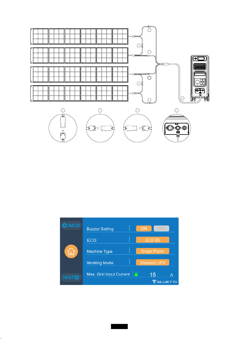
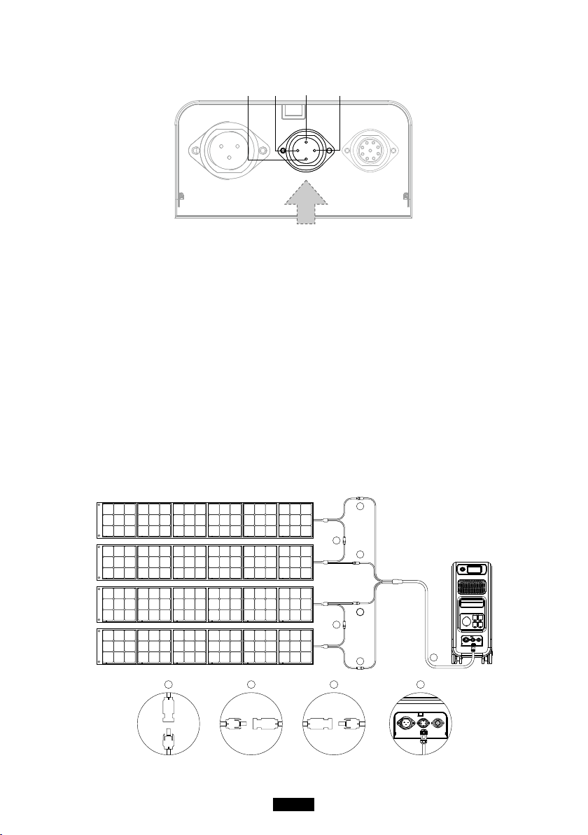
8.2.1. Charging Method 3: Solar Panels (via 4pin aviation-MC4 cable)
● For regular solar panels:
EP500Pro(dual MPPT) supports two PV charging methods with regular
portable panels and rigid panels.
Max current for single circuit: 12A.
Voltage Range: 12-150V.
Max. Input Power: 2400W.
a. User can connect 4-6 pieces of SP200 solar panels to the MC4 ports of
solar panels to the MC4-Aviation cable(gure 1/2/3).
b. Plug the Aviation plug to the middle input port on EP500Pro(gure 4).
● Enter “Settings” on touchscreen to set DC input source to “PV”.
Note: Select DC1 or DC2 Input Source according to the the certain DC
cables(check the label on cable No.3) you are connecting.
1
2 3
4
1
2
2
3
3
4
1
( Easy steps to solar charging )
23
Just Power On
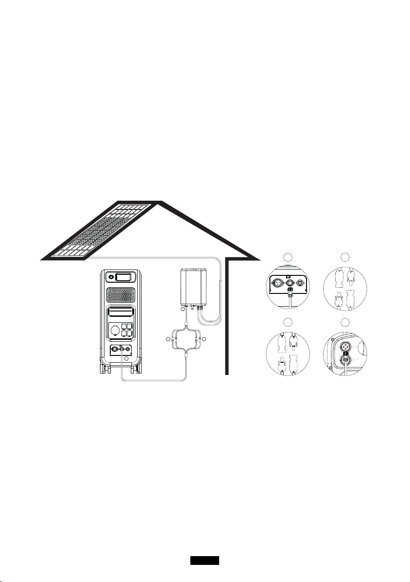
●For Roof/Rigid Panels:
If you choose roof panels to be the solar power source to recharge EP500Pro,
connect your roof panel with MC4-Aviation to EP500Pro through PV Step Down
Module will nish the installation.
PV Module (additional accessories) is required to drop down the voltage if
the open circuit voltage produced by your roof panels exceeds the limit of
EP500Pro can handle: 12-150VDC, 12A*2.
This PV module doesn’t work with solar panels that have built-in
microinverters, and open circuit voltage over 550V.
Please check BLUETTI Youtube channel: BLUETTI Ocial for detailed
instruction video.
a.DC Output Cable to EP500Pro
b.DC1 poles to PV1 poles
b
a
c
d
a
b
c
d
( PV Step Down Module )
c.DC2 poles to PV2 poles
d.DC Output Cable to D300S
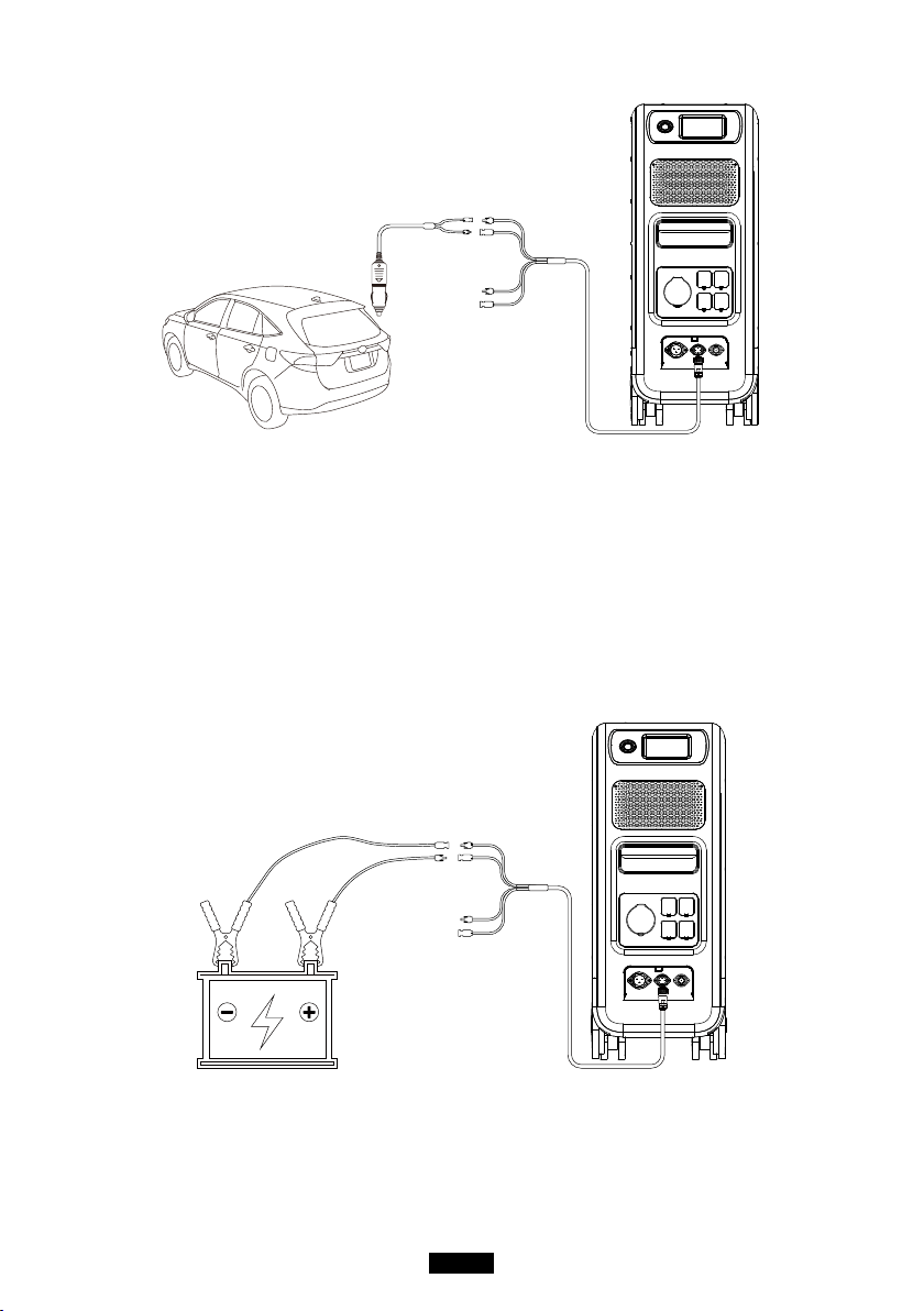
8.2.2. Charging Method 4 :Vehicle Charging
●Turn on EP500Pro.
●Connect car charging cable with MC4 to Aviation cable(cable No.3)
●Plug the car charging cable into CP2 and the cigarette lighter port on your car.
●Enter “Settings” on touchscreen to set DC input source to “Others”.
Note: Select DC1 or DC2 Input Source according to the the certain DC
cables(check the label on cable No.3) you are connecting.
24
BLUETTI
8.2.3. Charging method 5: Lead-acid Battery Charging
●Connect to the positive and negative poles of the battery through the battery
charging clamp(pay attention to distinguish the positive and negative poles of
the battery, the red pole on battery indicates the positive pole, and the black one
for negative pole).
●Enter “Settings” on touchscreen to set DC input source to “Others”.
Note: Select DC1 or DC2 Input Source according to the the certain DC
cables(check the label on cable No.3) you are connecting.
25
Just Power On
8.3. Dual Charging
Solar Panel
Second Adapter
Lead-acid Battery
Car
Wall OutletGenerator
Aviation Port 1(CP1)
Aviation
Port 2(CP2)
Charging Method 6 : Supports charging the EP500Pro with CP1 and CP2 at
same time. You can use any charging methods listed previously, simultaneous,to
maximize charging power input.
They are listed here again for your convenience. Select the method for both CP1
and CP2 to Dual Charging.
CP1 Charging Port Select:
Method 1: GEN charging cable
Method 2: AC charging cable
CP2 Charging Port Select:
DC Input1:
Method a: Solar panels(Set DC 1 Input Source as “PV” in “Settings”).
Method b: T500 Adaptor(Set DC 1 Input Source as “Others” in “Settings”).
Method c: 12V/24V Car Charger/Storage battery(Set DC 1 Input Source as “Others”
in “Settings”).
26
BLUETTI
DC Input2:
Method a: Solar panels(Set DC 2 Input Source as “PV” in “Settings”)
Method b: T500 Adaptor(Set DC 2 Input Source as “Others” in “Settings”)
Method c: 12V/24V Car Charger/Storage battery(Set DC 2 Input Source as “Others”
in “Settings”)
Method d:PV Parallel (PV parallel needs to be set in “Settings”)
8.4. How to calculate the recharging time of EP500Pro
5120Wh / Total recharging power + 0.5~1Hrs (trickle charging time) = fully
charging time estimation
Example: The total recharging power is 1100W(500W+600W) recharged by
AC and 2nd adapter at same time, the estimation time will be 5.13-5.63Hrs.
27
Just Power On
09. Discharge (OUTPUT)
The operational time of the EP500Pro is subject to many dierent factors such
ambient temperature, discharge rate, remaining battery capacity, and other
factors.
9.1. The Output Port
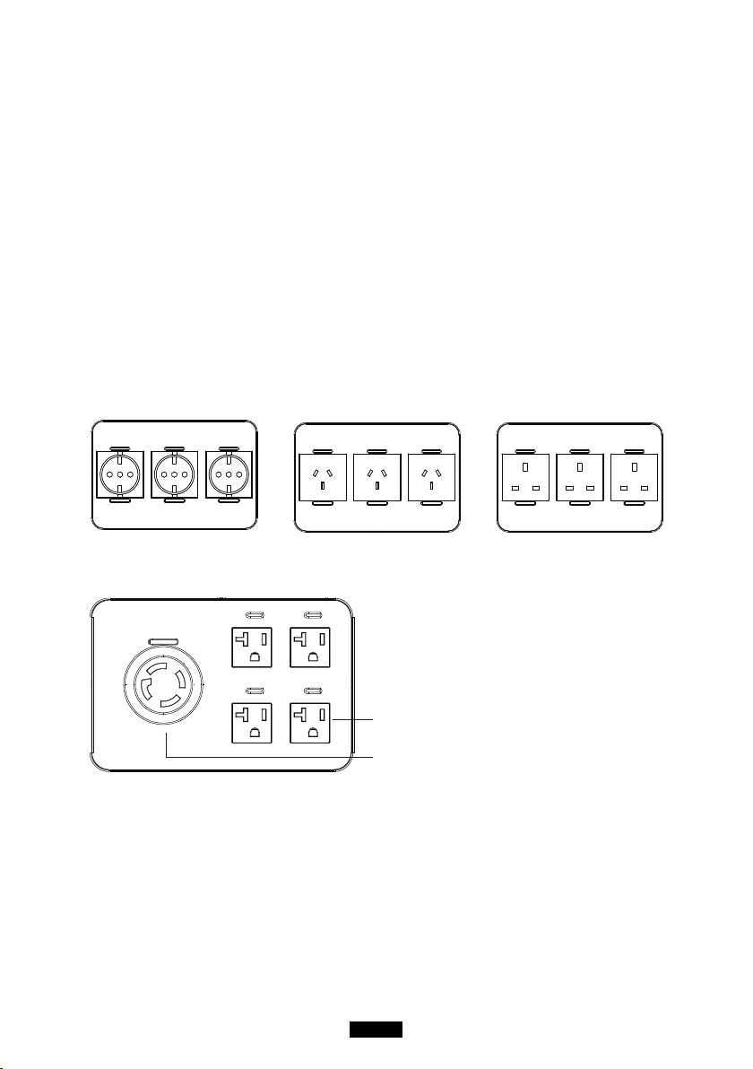
9.1.1. AC Output Port
●EP500Pro is equipped with *5 AC(US, JP version) / *3 AC(AU,EU,UK) outputs
with a continuous 3000W Max. power of output in total, and the ability to
support surges up to 6000W.
●Please make sure the combined power requirements of your appliances does not
exceed the limit of each port.
4 Standard AC Receptacle 20A
1 L 14-30 Receptacle 30A
JP/US Version 100-120V/20A
EU Version
3 * 220-240V/20A
AU Version
3 * 220-240V/20A
UK Version
3 * 220-240V/20A
NOTE, The limit of power of output:
3000W for EU/UK/EU version and the L 14-30 receptacle of US/JP Version.
2000W for the standard receptacle of US/JP Version.
28
BLUETTI
9.1.1. DC Output Port
1. *1 RV port
Special 30A output port can be adapted to appliances
widely, perfect for RV.
2. *1 Cigarette lighter port
Output port for devices with corresponding plug such
as vehicle-use vacuum, mini refrigerator.
3. *2 DC 5521
Traditional ports for routers/cameras, old laptop etc.
4. *2 USB-C
Can be used via USB-C to USB-C cable to charge most
devices in the market such as Pixel Phone, Macbook
Pro at 100W Max.
5. *2 USB-A (fast charging)
Quick charge USB-A ports.
6. *2 USB-A
Classic USB-A ports.
7. *2 Wireless charging pad
Place your phone(if wireless charging supported) on
the top of the AC200Max vertically, and turn on the DC
on homepage on screen.
1 2 3
4
6
7
5
9.2. Operation Time Estimation
●Kitchen Equipment
Refrigerator
700W(24h)
2.3 Days
Electric Fry Pan
1500W
2.7 Hrs
Microwave Oven
1000W
4.2 Hrs
Washer
500W(1000W)
4-7.66 Hrs
●Home Equipment
Space Heater
1500W
2.7 Hrs
Air Conditioning
8000Btu
1.6 Hrs
Smart Phone
18Wh
96 Times
Laptop
45Wh
59 Times
Desktop
300W
12 Hrs
CPAP
40W
64 Hrs

29
Just Power On
●Tools
Bench Grinder
1400W
2.9 Hrs
Welding Machine
1800W
2.3 Hrs
Circular Saw
1400W(2300W)
1.7-2.9 Hrs
●Transportation
Electric Vehicle(16A)
1800W
11.2-13.3 Miles
E-Bike
500W
7.6 Times
( The estimation operating time is only for reference )
9.3. How to Calculate the Operation Time
●5120Wh * DOD * η / (load W) = operation time (unit: hour/time)
If I want to know how many times 96W Macbook Pro could be recharged.
5120Wh * 90% * 90% / 96W = 43 times
●What is the depth of discharge (DoD)?
To extend the battery-life, the power station set the 90% DOD, which means that
only 90% of the battery capacity can be discharged. 10% of the energy is reserved
to avoid damage to the battery due to over-discharge.
η indicates local inverter eciency. DOD=90%, η =90%.
30
BLUETTI
10. UPS
10.1. UPS Description
An uninterruptible power supply or uninterruptible power source (UPS) is
an electrical apparatus that provides emergency power to a load when the
input power source or mains power fails. A UPS diers from an auxiliary or
emergency power system or standby generator in that it will provide near-
instantaneous protection from input power interruptions, by supplying energy
stored in batteries, supercapacitors, or ywheels.
10.1.1. FYI (For Your Information)
Battery SOC High indicates the limit of capacity the unit which can be charged
by the grid. If you set the Battery SOC High to 80% in Customized Mode, the
EP500Pro will be charged up to 80% from grid power. The remaining 20% will
be charged via solar panels (PV). This allows a discharged EP500Pro doing UPS
duties to quickly recharge from the grid when it comes back online to a certain
percentage before switching to solar panels to insure there is ample power for
the next power outage, but still charge via solar for clean and free energy.
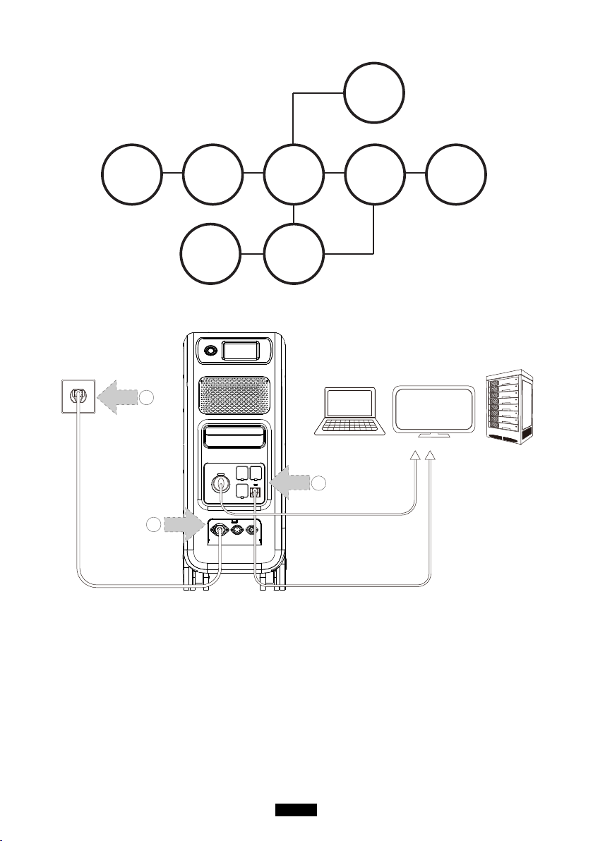
10.1.2. UPS working system introduction
31
Just Power On
BLUETTI
Sub Panel
BLUETTI
PV Module
Main Panel
Solar Panel
EP500
&
EP500Pro
Critical Load
≤2000W/3000W
or
≤4000W/6000W
Non-critical Load
≥2000W/3000W
or
≥4000W/6000W
Grid
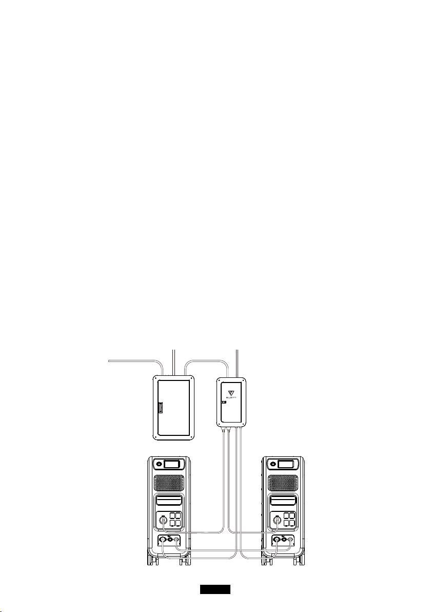
( EP500Pro grid-tied home power back-up system with Sub Panel and roof panels )
1
2
3
( Plug-in UPS system )
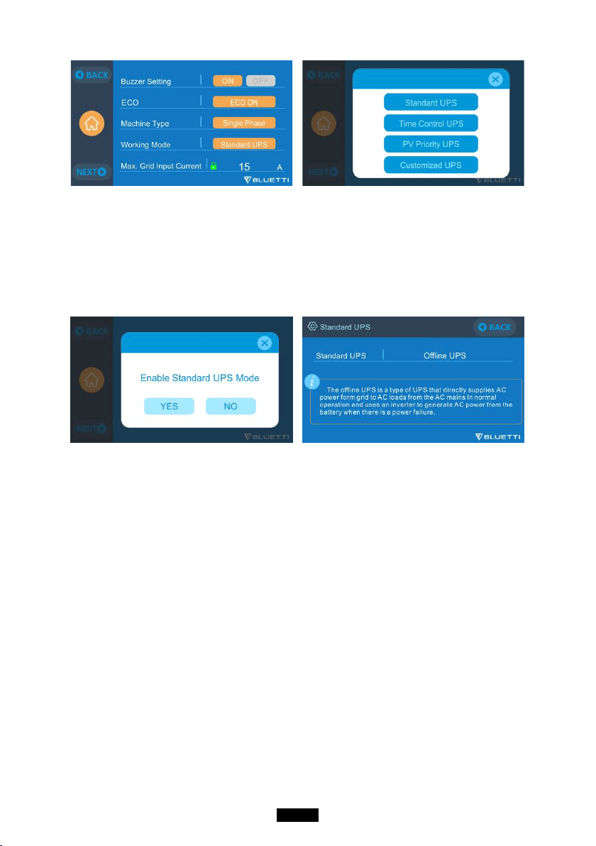
10.1.3. Turn On UPS Function
●Select “Setting” on the main touchscreen interface. Select “Next” and select
“Working Mode” to choose UPS Mode.
●The default working mode is “Standard UPS Mode”.
32
BLUETTI
10.2. Enable UPS Running Mode
10.2.1 Standard UPS Mode
●Offline UPS: Basic UPS Working Mode
EP500Pro will power your load directly from the grid and maintain a 100%
charge. When grid power fails, the EP500Pro switches to internal batteries.
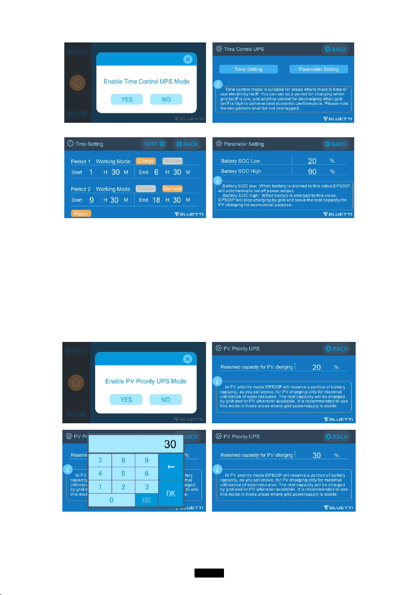
10.2.2. Time Control UPS Mode
●This allows you to set the times that EP500Pro will be charged via grid power
and the times to run loads from its battery.
Charge Time: Set the time of EP500Pro when to be charged by grid to avoid
the higher time-of-use electricity (peak) rates, normally set to off-peak times.
Discharge Time: Set the time to use the EP500Pro batteries to power the loads
connected on AC output port of EP500Pro or Sub Panel (Optional Purchase).
Usually set during peak-rate hours.
●Parameter Setting:
Battery SOC Low: When the remaining capacity of EP500Pro is under the
preset Battery SOC Low state, the EP500Pro will stop powering loads connected
to the AC output ports of the EP500Pro or Sub Panel (Optional Purchase).
Battery SOC High: The maximum capacity EP500Pro can be charged via grid.
The remaining percentage will be charged either by solar (PV) or 2nd adapter.
33
Just Power On
10.2.3. PV Priority UPS Mode
●PV Priority Mode: This mode is recommended for areas with stable grid power.
The battery will be recharged mainly by PV for power savings.
●Note: In PV Priority Mode, EP500Pro can only be recharged via grid to
30% capacity, and also discharge to 30% of the capacity (you can tweak
it to 100% for full grid charging manually on touchscreen or App) as the
" Reserved capacity for PV charging". And rest of the capacity will be fully
charged from either solar power or 2 adaptors.
34
BLUETTI
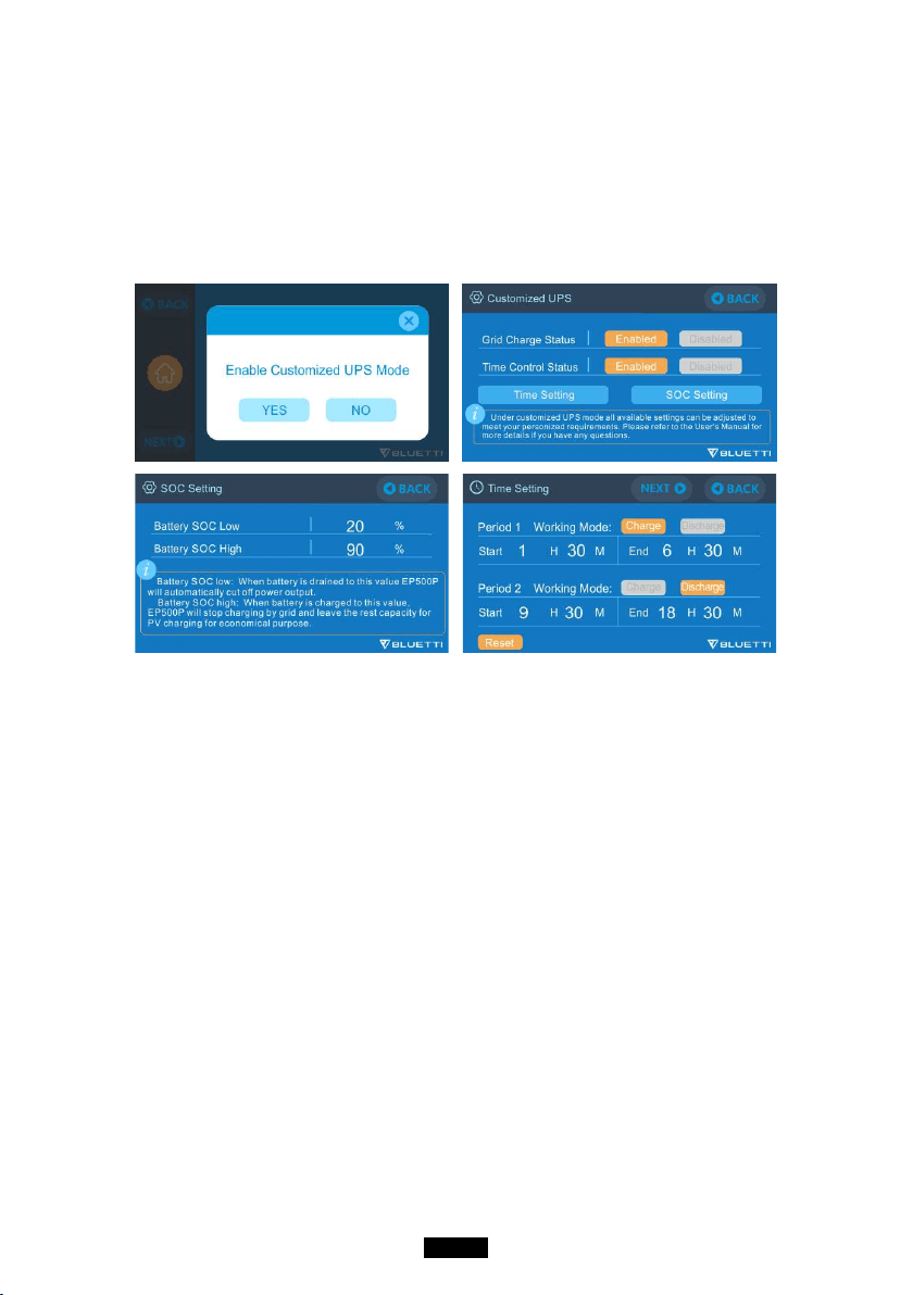
10.2.4. Customized UPS Mode
●Charge/Discharge time, and High/Low Battery SOC can be set in this UPS mode.
●Ability to disable the grid charging. The unit will not charge batteries from grid.
●Apart from Time Control UPS, the main switch of grid charging and time mode
settings are involved. The setting of turning the grid/time setting ON/OFF will
take effect on both PV Priority Mode and Time Control Mode.
35
Just Power On
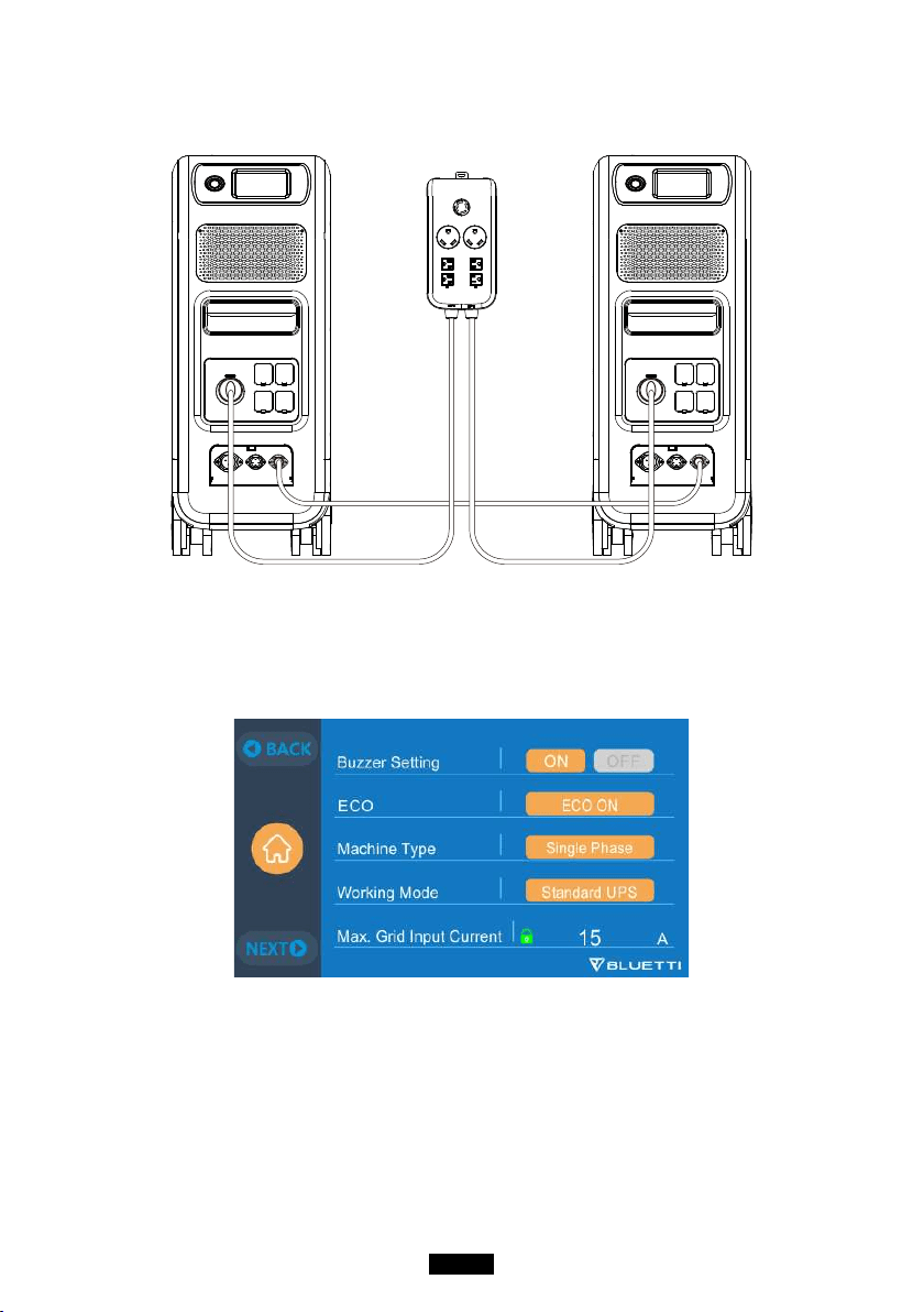
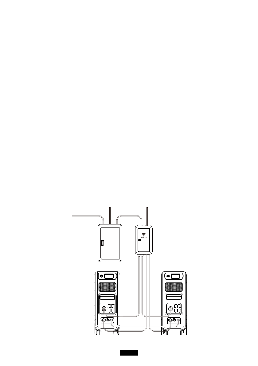
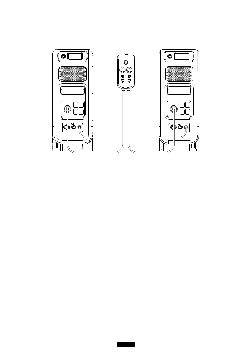
11. Split Phase Function
Note:
(1) Please disconnect the AC charging cable for both EP500Pro units while
binding into split phase box.
(2) Certifcated Technician is required to build the split phase system to
power the Power Cabinet or Sub Panel.
Warning: If you insist to charge the EP500Pro which has been connected
into split phase box already, please make sure the L1/L2/N wire is set at
the right place or the EP500Pro will be damaged.
L: Live wire N: Neutral wire
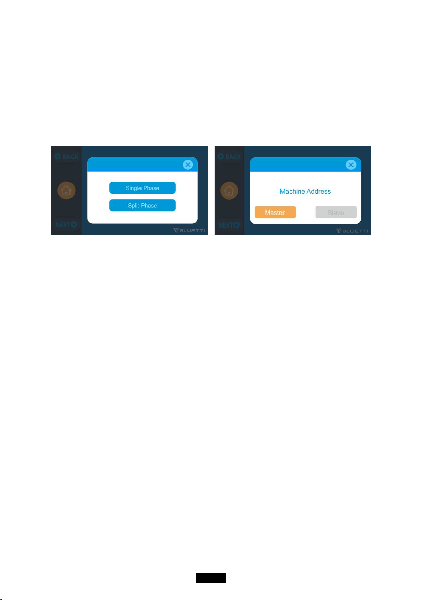
●The “Machine Type” setting on screen is used to enable or disable Split
Phase output.Split-Phase output is achieved by bonding two EP500Pro into one
power system to double the available output power, voltage, and capacity.
●“Split Phase” is only used for connecting both *2 EP500Pro together (exclusive
for the 100-120V version of the EP500Pro). A Fusion Box(P30A) is required (sold
separately).
●Launch Split Phase Function:
Note: Only one touchscreen will be active when two EP500Pro units are
connected.
If one of the EP500Pro is out of power, the Split Phase Bonding function
will deactivate automatically.
Step 1: Plug the output cables from each of the two EP500Pro to the Split Fusion
36
BLUETTI
Box Pro.
Step 2: Plug the communication cables from each of the two EP500Pro’s to the Split
Fusion Box Pro.
Step 3: Set the Machine Type to "Split Phase" on EP500Pro either.
Step 4: Select "Master" or "Slave" on the operating EP500Pro. Select "Master" will
set the operating EP500Pro as the one to control both two EP500Pro. Select "Slave"
will set the operating EP500Pro as the other EP500Pro as the "Master" one.
CONNECTION 1 (Standard Mode)
“Single Phase” is set as the default machine type if you are operating a single
EP500Pro. This is the only and correct setting if a single EP500Pro is being used.
Machine type is just used to set for Split Phase, “Split Phase” is only used for
connecting both *2 EP500Pro (exclusive for 100-120V Version) bonded 2 pairs
of EP500Pro to one power system to double the output power, voltage, so as to
capacity. Please refer to Split Phase setting for detailed information.
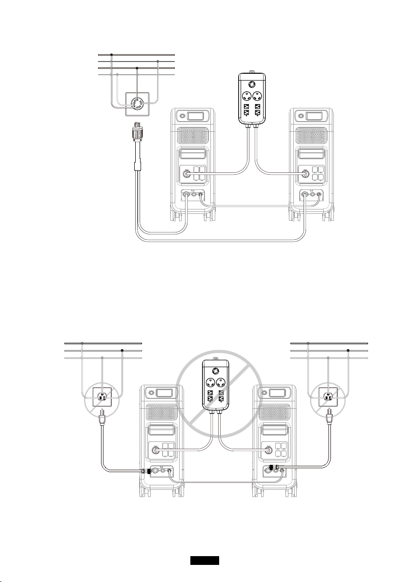
CONNECTION 2 (Power Mode)
In Split Phase Power System, it is recommended that you choose our matching
AC input cable. The AC input ports of the two machines are connected to
L1,N,PE and L2,N,PE. Make sure that the phase of the two machines is correct.
This AC Input Cable(Optional Purchase) is designed to match Split Phase
System.
One end of the cable is connected to the NEMA L14-30 socket, and the other
end is connected to the AC input interface of both two units through aviation
plug.It must be ensured that the phase of the two machines is correct.
The current capacity of AC input plug shall be ≥ 30A.
37
Just Power On
L1 N PE
PE
G(PE)
L2
W(N)
L1
X(L1)
N
Y(L2)
L2 N PE
AC Input
Cable(L14-30)
WRONG CONNECTION
It`s forbidden to connect EP500Pro into Split Phase System when AC charging is
ON, please use AC Input Cable(Oponal Purchase) to charge both of your power
staons in Split Phase System. Wrong Connecon will damage the baery inside
the power staon and your warranty will be invalid.
PE
G(PE)
W(N)
L1
X(L1)
N
PE
G(PE)
W(N)
L1
X(L1)
N

38
BLUETTI
12. Technical Specication
Model
EP500Pro
JP
EP500Pro
US
EP500Pro
EU/UK/AU
Net Weight
83kg (183.0lbs)
Dimensions 580*300*760mm (22.8*11.8*29.9in)
Charge Temperature 0-40℃ (32-104 ℉ )
Discharge Temperature -20-40℃ (-4-104 ℉ )
Storage Temperature -25-40℃ (-13-104 ℉ )
Working Environment
Humidity
10-90%
Certication PSE, FCC, CE, UN38.3, msds, UL, SAA and ROHS
Capacity 5120Wh (100Ah)
Battery Type LiFePO4
Standard Battery Voltage 51.2VDC
Battery Cell Voltage Range
44.8-57.6VDC
Short-circuit Protection Included
Over-temperature
Protection
Included
MPPT Built-in
Over-temperature Protection
Discharge Over-
temperature
65℃
Discharge Over-
temperature Recovery
55℃
Charge Over-temperature 55℃
Charge Over-temperature
Recovery
45℃
AC Output
AC Inverter *5 3000W total *3 3000W total

39
Just Power On
Rated Output Voltage 100VAC 120VAC 220-240VAC
Rated Output Frequency 50/60Hz
Rated Continuous Power 3000W
Rated Output Current 30A 25A 13A
Power of Over-load
3100W < load < 3750W, 2min;
3750W < load < 4500W, 5s;
4500W < load < 6000W, 500ms
Eciency >88%
THD <5%
DC Output
Cigarette Lighter Port *1 12VDC/10A
DC 5521 *2 12VDC/10A
USB-A *2 5VDC/3A total
USB-A(fast charging) *2 3.6-12VDC/36W
USB-C (Type-C) *2 20VDC/5A; 5-15VDC/3A
Wireless Charging Pad *2 5W/7.5W/10W/15W
RV Port *1 12VDC/30A 418W>load, 2S
Note: Cigarette lighter port shares 10A current with *2 DC5521 ports in
parallel circuit.
AC Input
Input Voltage 85-110VAC/JP 102-132VAC/US
207-253VAC
EU/UK/AU
Input Frequency 47Hz-63Hz
Max. Input Current 30A
Congurable Input Current Preset at 15A, can be changed on screen
AC Charging Voltage Range 90-264VAC
AC Charging Frequency Range 47Hz-63Hz
Power of Charging 3000W Max
PV Input

40
BLUETTI
Max. Input Voltage 150VDC
MPPT Voltage Range 12-150VDC
Max. Power of Input 1200W*2
Rated Input Current 12A*2
13. Storage and Maintenance
●Please turn off the unit and charge it to 50-70% of capacity before storing.
●To help preserve battery health, please discharge and fully charge the unit
atleast once every 6 months.
●Ensure proper ventilation when in use or in storage.
●Keep unit away from any combustible materials or gases. (32-113 ℉ , 0-45℃ ).
A clean and dry environment is strongly recommended.
●Dry, non-abrasive cloths to clean the exterior from dust and debris every so
often is highly recommended.
●Keep the unit away from children and pets.
●Do not stack anything on the top of the unit while in use or in storage.
●Avoid exposing the unit to rainy or wet environment and in direct sunlight.

41
Just Power On
14. Troubleshooting
Error
Code
Error List Troubleshooting
001 D-AMCU Warning
Please contact with the dealer if the error still
exists after rebooting the unit.
002 D-BMS Warning
Please contact with the dealer if the error still
exists after rebooting the unit.
003 D-A Communication Error
Please contact with the dealer if the error still
exists after rebooting the unit.
004
Battery Voltage High
-Hardware
Please contact with the dealer if the error still
exists after rebooting the unit.
005
BUS Voltage High-
Hardware
Please contact with the dealer if the error still
exists after rebooting the unit.
006
SPS Voltage Low-
Hardware
Please contact with the dealer if the error still
exists after rebooting the unit.
007 Fan Warning-Hardware
Clean or replace the fan to ensure proper
ventilation.
Please contact with the dealer if the error still
exists after rebooting the unit.
008
OCP (Over Current
Protection)- Hardware
Please contact with the dealer if the error still
exists after rebooting the unit.
009 LLC Soft-Start Failure
Please contact with the dealer if the error still
exists after rebooting the unit.
010 BUS Soft-Start Failure
Please contact with the dealer if the error still
exists after rebooting the unit.
011 H-BUS Voltage High
Please contact with the dealer if the error still
exists after rebooting the unit.
012 Bus Voltage High
Please contact with the dealer if the error still
exists after rebooting the unit.
013 LLC-Bus Voltage High
Please contact with the dealer if the error still
exists after rebooting the unit.
014 Bus Voltage Low
Please contact with the dealer if the error still
exists after rebooting the unit.

42
BLUETTI
015 DC Input Voltage High
Please contact with the dealer if the error still
exists after rebooting the unit.
016 DC Input Voltage Low
Please contact with the dealer if the error still
exists after rebooting the unit.
017 DC Input Over Current
Please contact with the dealer if the error still
exists after rebooting the unit.
018
Inverter Output Over
Current
The output power of load exceeds.
Please contact with the dealer if the error still
exists after rebooting the unit.
019 Inverter Voltage High
Please check if the output of load meets the
specications of the unit.
Turn on the AC after rebooting, please contact
with the dealer if the error still exists.
020 Inverter Voltage Low
Please check if the output of the load meets
the specications of the unit.
Turn on the AC after rebooting, please contact
with the dealer if the error still exists.
021 Grid Input Over Current
Please check if the input of the current meets
the specications of the unit.
Turn on the AC after rebooting, please contact
with the dealer if the error still exists.
022
Inverter Output Short
circuit
Please disconnect the load to make sure the
load has been connected properly.
Click to clear the alarm history.
023
Inverter Over-load
Protection
Please disconnect the load to make sure the
output power of loads meet the limit of the
unit.
Click to clear the alarm history.
024 Phase Integration Error
Check the input wire and whether the “Master”
unit or “Slave”unit can work well.
025 AC Relay Short Circuit
Please contact with the dealer if the error still
exists after rebooting the unit.
026 AC Relay Open Circuit
Please contact with the dealer if the error still
exists after rebooting the unit.

43
Just Power On
027 Load Relay Short Circuit
Please contact with the dealer if the error still
exists after rebooting the unit.
028 Load Relay Open Circuit
Please contact with the dealer if the error still
exists after rebooting the unit.
029 INV Soft-Start Failure
Please contact with the dealer if the error still
exists after rebooting the unit.
049 PV1 Over Current
Please contact with the dealer if the error still
exists after rebooting the unit.
050 PV2 Over Current
Please contact with the dealer if the error still
exists after rebooting the unit.
051 PV1 Over Voltage
Please check if the open circuit voltage
of solar panels exceeds the input voltage
standard of EP500Pro.
052 PV2 Over Voltage
Please check if the open circuit voltage
of solar panels exceeds the input voltage
standard of EP500Pro.
053 D-BAT Full The battery is full.
054 D-BAT Drained
Empty of battery.
When SOC > 5%,the alarm is cleared.You
need to turn AC ON again on the screen.
055
Inverter Overload
Warning
The output power of load exceeds.
056 AC Overload Warining The output power of load exceeds.
057 Grid Voltage High
Please check whether the grid voltage ts the
input voltage standard of EP500Pro.
058 Grid Voltage Low
Please check whether the grid voltage ts the
input voltage standard of EP500Pro.
059 Grid Frequency High
Please check whether the grid frequency ts
the input frequency of EP500Pro.
060 Grid Frequency Low
Please check whether the grid frequency ts
the input frequency of EP500Pro.
061
Multi Communication
Error
Please check whether the communication
cable is connected correctly.
Clear the alarm history or restart the unit.

44
BLUETTI
062 Multi Address Error
Please check whether the communication
cable is connected correctly.
Clear the alarm history or restart the unit.
063
Multi Synchronization
Error
Please check whether the communication
cable is connected correctly.
Clear the alarm history or restart the unit.
064 Multi Brak Phase Error
Please check if the input of the AC voltage
meets the specications of the unit.
Clear the alarm history or restart the unit.
065 PV Paralleling Error
Please check whether the PV parapllel enable
setting is consistent with the PV input.
Please contact with the dealer if the error still
exists after rebooting the unit.
081
BMS Communication
Interrupt
Please contact with the dealer if the error still
exists after rebooting the unit.
082
LCD Communication
Interrupt
Please contact with the dealer if the error still
exists after rebooting the unit.
083
EEPROM Read & Write
Error
Please contact with the dealer if the error still
exists after rebooting the unit.
084 DSP Conguration Error
Please contact with the dealer if the error still
exists after rebooting the unit.
085 RTC Read & Write Error
Please contact with the dealer if the error still
exists after rebooting the unit.
086 12V/30A Port OCP
Please disconnect the appliances on DC
12V/30A ports.
Clear the alarm history or restart the unit.
087 12V/10A Port OCP
Please disconnect the appliances on DC
12V/10A ports.
Clear the alarm history or restart the unit.
088
USB/TYPE-C/PD Port
Current High
Please disconnect the appliances on USB
ports.
Clear the alarm history or restart the unit.
089
DC12V/30A Output
Current High
Please disconnect the appliances on DC
12V/30A ports.
Clear the alarm history or restart the unit.

45
Just Power On
090
DC12V/10A Output
Current High
Please disconnect the appliances on DC
12V/10A ports.
Clear the alarm history or restart the unit.
091
DC Output Soft Start
Failure
Please contact with the dealer if the error still
exists after rebooting the unit.
092
DC12V/30A Output Short
Circuit
Please disconnect the appliances on DC
output ports.
093
DC12V/10A Output Short
Circuit
Please disconnect the appliances on DC
output ports.
094
USB/TYPE-C/PD Port
Locked
Please disconnect the load to make sure the output
power of loads meet the limit of the unit.
Please contact with the dealer if the error still
exists after rebooting the unit.
095 12V/30A DC Port Locked
Please disconnect the load to make sure the
output power of loads meet the limit of the unit.
Please contact with the dealer if the error still
exists after rebooting the unit.
096 12V/10A DC Port Locked
Please disconnect the load to make sure the
output power of loads meet the limit of the
unit.
Please contact with the dealer if the error still
exists after rebooting the unit.
097
BMS Temperature
Abnormal
Please store EP500Pro at the recommended
temperature and leave it until the temperature
inside back to the normal standard.
098 BMS Over Voltage
Please contact with the dealer if the error still
exists after rebooting the unit.
099 BMS Low Voltage
Please contact with the dealer if the error still
exists after rebooting the unit.
100 BMS Over Current
Please contact with the dealer if the error still
exists after rebooting the unit.
101 BMS Precharge Error
Please contact with the dealer if the error still
exists after rebooting the unit.
102 BMS Output Short Circuit
Please contact with the dealer if the error still
exists after rebooting the unit.

46
BLUETTI
107 NTC Faulty
Please leave the unit at the recommended
temperature few hours to recover.
Please contact with the dealer if the error still
exists after rebooting the unit.
108 Fan Faulty
Clean or replace the fan to ensure proper
ventilation.
Please contact with the dealer if the error still
exists after rebooting the unit.
15. FAQ (Frequently Asked Questions)
●How to claim the warranty and extended warranty?
Please place your after-sale requirement as the warranty card written to the
vendor where you order the product, the extended warranty(if purchased)
will take eects after the default warranty is void.
●Can it be upgraded?
The rmware including ARM, DSP, IoT and BMS can be upgraded online
through OTA, and the parameters of the machine will be adjusted and
optimized.
●Can it be charged and discharged at the same time?
Yes, the unit supports pass-through charging function for both AC and DC
outputs. We recommend to fully charge the unit at least once per month to
extend battery life.
●How many UPS modes are there?
There are 4 types of UPS Mode you can choose freely, Economic Mode, UPS
Mode, Peak-avoiding Mode and Advanced Mode.
There can both be set to work oine and online.
●What is the UPS switching latency?

47
Just Power On
There are two types of working conditions of UPS for EP500Pro.
No delay for online UPS; 20ms from oine UPS.
●Can I connected my two EP500Pro with Fusion Box to achieve double the
output power, voltage and capacity.
You can connect two EP500Pro OR two EP500Pro with a Fusion Box. The
units must be of the same type and the correct Fusion Box (P020A for
EP500Pro, P030A for EP500Pro). You cannot mix a EP500Pro and EP500Pro
with a Fusion Box.
●Can I use third-party solar panels to charge the unit?
Yes, the third-party solar panels are available as long as they contain MC4
connectors, besides the voltage (in series or parallel) is between 55V to 145V
and the maximum input power is 1200W.
If the open circuit voltage of the panels is less than 550V, you can choose PV
Module to step down the voltage to achieve solar charging.
●How do I know whether my appliance can work well with the power station?
Calculate how much the continuous loads are for your appliances are in total.
As long as they do not exceed the rated output power of the power station, it
should work.
●How can I connect the product to my home circuit breaker box?
To install the grid-tie power system, an electrician with a professional
technician certicate is required, connect the wires of critical equipment from
your main electrical box to the BLUETTI Sub Panel (optional purchase).

48
BLUETTI
16. Declaration
●Some changes may not be noticed specically such as appearance or
specications due to the exterior material or hardware improvement of the
product.
●Our company shall not be liable for any damage caused by force majeure
such as re, typhoon, ood, earthquake or the user's intentional negligence,
misuse or other abnormal conditions.
●No compensation for damages shall be made for utilizing non-standard
adapters and accessories.
●Our company will not bear all responsibilities if the damage is caused by not
operating the product properly according to the use method in operation
manual.
●This unit is not suitable for use on the relevant equipment or machines
involving:
Personal safety, such as atomic energy devices, aerospace devices,
transportation devices, medical devices, etc., or any equipment or machines
that require highly reliable power sources. We are not responsible for
accidents, res, or wrongful or negligent actions done to the machine and
equipment which results in damage.

P/N:17.0303.0379-00A0