Loading ...
2
FIG. 1
FIG. 2
FIG. 3
KNOCKOUTS
DISCOS
REMOVIBLES
FIG. 4
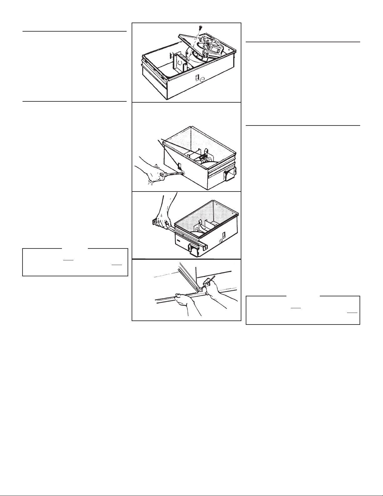
PREPARE THE FAN
1. Unplug the fan assembly from the BLACK recep-
tacle. Remove the plastic bag and set it aside.
2. Remove the mounting screw and carefully lift the
fan assembly out of the housing. (FIG. 1)
3. Refer to the wiring diagram of you unit on the next
page. Remove appropriate knockout(s) by inserting
a screwdriver blade into slot(s) and bending it back
and forth to break tabs. (FIG. 2)
4. Insert the adjustable mounting brackets into the
bracket channels on the housing. (FIG. 3)
INSTALL THE FAN
5. Choose the location for your fan. For best possible
performance, use the shortest possible duct run and
a minimum number of elbows.
6. Position unit between joists and extend mounting
brackets. Position brackets such that bottom edge
of housing will be flush with finished ceiling. Mark
the top of keyhole slot on all four mounting brackets.
(FIG. 4)
7. Remove unit temporarily, and pound nails partially
into joists at all four marked locations. (FIG. 5)
8. Hang unit from nails and use embossed measur-
ing guides to check if unit will be flush with finished
ceiling. Pound nails tight. For wide joist centers:
A #8 x 3/8 self-tapping screw can be used to join
extended brackets together and create a rigid mount.
To ensure a noise-free mount, crimp the bracket
channels tightly around mounting brackets. (FIG. 6)
9. Snap the damper/duct connector onto housing.
Make sure that tabs on the connector lock in housing
slots. (Top of damper/duct connector will be flush
with top of housing). (FIG. 7)
NOTE: Make sure damper flap is in place inside of
duct connector. If it is not:
Squeeze top and bottom
of connector to
snap flap back into place.
10. Wire unit using appropriate diagram.
11. Replace fan assembly removed in STEP 2 and plug
it into BLACK receptacle.
CAUTION
To avoid the possibility of overheating and/
or fire, the grille must be installed as shown
in FIG. 8. Acorn nut and tooth washer must
attach to threaded rod through proper hole in
light reflector.
12. Slide the light reflector into opening in grille and plug
into WHITE receptacle. Use acorn nut and tooth
washer from plastic bag to attach grille reflector as-
sembly to threaded rod on housing. Tighten securely
using pliers or nut driver. Install a light bulb - 100
watt maximum. (FIG. 8)
13. Install light lens by (1) hooking one of its tabs into
notch in grille/reflector assembly; (2) apply light
pressure to other tab with fingertips and (3) snap
into place. (FIG. 9)
PREPARACION DEL
VENTILADOR
1. Desconecte el conjunto del ventilador del enchufe
NEGRO. Saque la bolsa de plástico y déjela a un lado.
2. Saque el tornillo de montaje y levante con cuidado el
conjunto del ventilador fuera de la caja. (FIG. 1)
3. Refiérase al diagrama de conexiones de la unidad
en la página siguiente. Saque los discos removibles
apropiados introduciendo la punta del destornillador
en las ranuras y moviendo éste de un lado a otro hasta
romper las lengüetas. (FIG. 2)
4. Meta los soportes de montaje ajustables en los canales
para éstos en la caja. (FIG. 3)
INSTALACION DEL
VENTILADOR
5. Elija la posición para su ventilador. Para el mejor
desempeño, use la menor cantidad de ducto y el menor
número posible de codos.
6. Sitúe la unidad entre las vigas y extienda los soportes
de montaje. Coloque los soportes de manera que el
extremo inferior de la caja esté al nivel del cielo raso
acabado. Marque la parte superior de la ranura en las
cuatro soportes de montaje. (FIG. 4)
7. Saque la unidad por unos momentos, y clave los clavos
parcialmente en las vigas en las cuatro posiciones
marcadas. (FIG. 5)
8. Cuelgue la unidad de los clavos y use las guías
estampadas de medición para comprobar si la unidad se
encuentra a nivel con el cielo raso acabado. Termine de
clavar los clavos. En caso de que el centro de las vigas
sea ancho: se puede usar un tornillo autorroscante #8 x
3/8 para juntar los soportes extendidos y crear un soporte
de montaje rígido. Para asegurar un montaje silencioso,
pliegue los canales alrededor de los soportes de montaje.
(FIG. 6)
9. Inserte la conexión del amortiguador/ducto en la
caja. Asegúrese de que las lengüetas del conector se
cierran en las ranuras de la caja.(La parte superior
del amortiguador/ducto debe estar a nivel con la parte
superior de la caja). (FIG. 7)
NOTA: Asegúrese de que la tapa del regulador de tiro
esté colocada dentro del conector del conducto. Si no lo
está:
Comprima la parte superior e inferior del conector
para
volver a colocar la tapa en su lugar.
10. Conecte la unidad de acuerdo con el diagrama apropiado.
11. Vuelva a colocar el conjunto del ventilador que se sacó
en el paso 2 y conéctelo al enchufe NEGRO.
PRECAUCION
Para evitar la posibilidad de un sobrecalentamiento y/o
un incendio, la rejilla debe ser instalada se muestra en
la figura 8. La tuerca ciega y arandela dentada debe
conectarse a la varilla roscada a través del agujero
apropiado en el reflector de luz.
12. Deslice el reflector de luz en la abertura de la rejilla y
conéctelo al enchufe BLANCO. Use el tornillo y arandela
dentada para sujetar la rejilla y el conjunto del reflector
al soporte del motor. Instale una lámpara de un máximo
de 100 vatios. (FIG. 8)
13. Para instalar el lente de la luz: 1)Enganche una de las
lengüetas en la muesca del conjunto rejilla/reflector; 2)
Aplique un poco de presión a la otra lengüeta con los
dedos, y 3)Encájela en su sitio. (FIG. 9)
Loading ...
Loading ...