Loading ...
Loading ...
Page 3 of 6
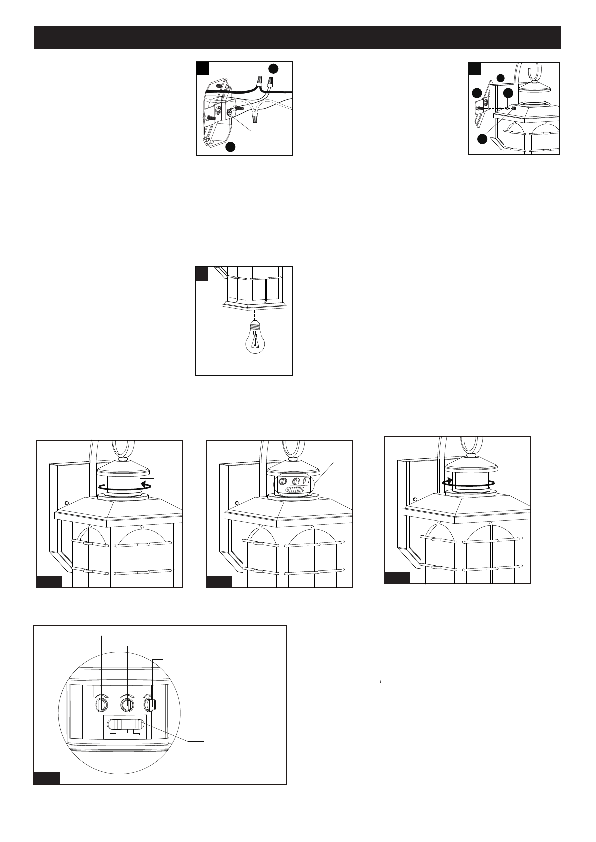
ASSEMBLY INSTRUCTIONS (continued)
5. Install a bulb (not included).
See relamping label at socket
area or packaging for maximum
wattage allowed.
Turn on the power at fuse or circuit box
The Position of Control Panel
Step 1: Rotate the sensor lens from left side to right side
to show the adjustable knobs and slide switch.
(See Fig.1)
Step 2: Adjust time
low level brightness and sensitivity
by knobs and choose the mode you want by
slide switch. (See Fig.2 and Fig A).
Step 3: Restore the sensor lens to original position.
(See Fig.3)
“Time” Knob
“Sens” Knob
Slide Switch
“Low Level” Knob
Time Low Level
Sens
Test
Off
Auto
PC
Fig.A
3. Pull out the source wires from the
outlet box. Make wire connections
using wire connectors (CC) as
follows:
• Connect the hot wire (usually
black insulation) from the fixture
to the black wire from the power
source.
• Connect the neutral wire (usually white insulation) from
the fixture to the white wire from the power source.
• Attach the fixture grounding wire (usually green
insulation or bare wire) to the cross bar unit (AA) with
the green grounding screw, then connect it to the
house grounding wire with the wire connector (CC).
Carefully put all of the wires back into the outlet box.
3
AA
CC
Green Grounding
Screw
4. Attach the backplate (A) of the
fixture to the cross bar unit (AA) by
aligning and inserting the two
headless screws from the cross bar
unit (AA) into the open holes on the
backplate (A), then place the two
rubber pads (EE) over the exposed
headless screws before screwing
the two ball nuts (DD).
Note: With silicone caulking compound, caulk
completely around where the backplate meets with
the wall surface to prevent water from seeping into
the outlet box.
5
Max.60W Type A Bulb
(not included)
4
A
EE
AA
DD
Sensor
Lens
Fig.1
Sensor
Lens
Fig.1
Fig.1
View Fig.A
190718
Loading ...
Loading ...
Loading ...