Loading ...
Loading ...
Loading ...
Vac Assembly
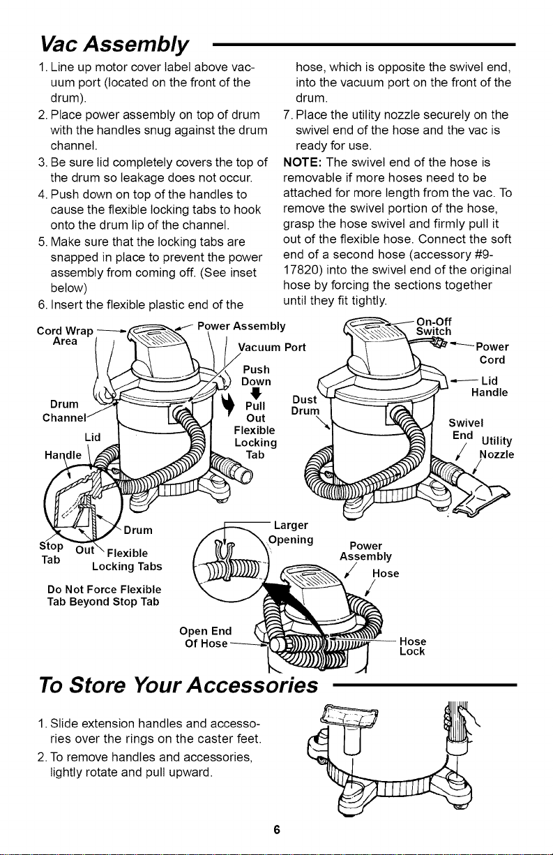
1.Line up motor cover label above vac-
uum port (located on the front of the
drum).
2. Place power assembly on top of drum
with the handles snug against the drum
channel.
3. Be sure lid completely covers the top of
the drum so leakage does not occur.
4. Push down on top of the handles to
cause the flexible locking tabs to hook
onto the drum lip of the channel.
5. Make sure that the locking tabs are
snapped in place to prevent the power
assembly from coming off. (See inset
below)
6. Insert the flexible plastic end of the
hose, which isopposite the swivel end,
intothe vacuum port on the front of the
drum.
7. Place the utility nozzle securely on the
swivel end of the hose and the vac is
ready for use.
NOTE: The swivel end of the hose is
removable if more hoses need to be
attached for more length from the vac. To
remove the swivel portion of the hose,
grasp the hose swivel and firmly pull it
out of the flexible hose. Connect the soft
end of a second hose (accessory #9-
17820) into the swivel end of the original
hose by forcing the sections together
until they fit tightly.
Wrap _
CordArea | ] _ \ I VacuumPor t
s " Power Assembly
t _.-_.J--_ Down
_t_/J/_Li i Du
Drum Pull
Channel/__ :] • Out Dru%
.-, I_ _1 Flexible
LIQ,_It ._I Locking
f
,_ Larger
Drum
Stop _ Flexible
Tab
Locking Tabs
Do Not Force Flexible
Tab Beyond Stop Tab
Power
Assembly
Hose
/
Switch
Power
Cord
Swivel
Utility
Nozzle
Open End
Of
Hose
Lock
To Store Your Accessories
1. Slide extension handles and accesso-
ries over the rings on the caster feet.
2. To remove handles and accessories,
lightly rotate and pull upward.
Loading ...
Loading ...
Loading ...