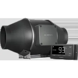
AC Infinity AI-CLT6 Fan
Product's Documents
Below are documents related to this product, you can read online or download:
- Owner's manual - (English) Read Online | Download pdf
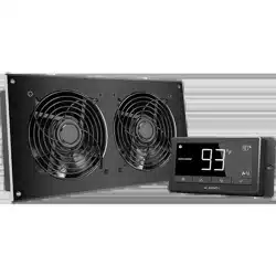
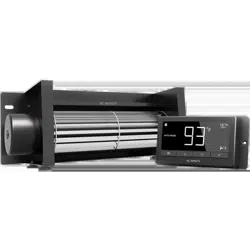
Intake and Exhaust
FAN SPEED ADJUSTING
The controller features a single button that controls the fan speed from 0-8. Pressing the speed button increases the fan speed in one unit increments. Pressing the button at the 8 setting will set the fan speed back to 0.
POWERING ON/OFF
Holding the speed button for 4 seconds will turn the fan OFF. Pressing it again from OFF will turn the fan ON at its last speed setting.
MODE SETTING
Pressing the Mode button will cycle through the controller’s available programming modes and settings: ON Mode, OFF Mode, TIMER Mode, AUTO Mode (4 triggers), ALARM Settings (4 settings).
ON MODE
In this mode, the fan will run continuously regardless of temperature or humidity. Use this mode to set the fan's maximum blowing strength, ranging from 0-10, when triggers are activated.
OFF MODE
In this mode, the fan will not run regardless of temperature or humidity. Pushing the up or down button will change the display’s brightness, ranging in 1/2/3/A3. On setting A3, the display will dim its brightness down to 1 if the device is left unattended for 30 seconds. Holding the up or down button will change the display’s units to F or C, respectively.
STEP 1 Unscrew and loosen the metal rings using a Phillips screwdriver and pliers.
STEP 2 Remove the motor box from the flange bracket.
STEP 3 Use the flange bracket to set your desired fan position. Mark the four mounting holes.
STEP 4 Drill four holes into the marked locations. Make sure your mounting area is structurally sound and free from obstruction.
STEP 5 If you are mounting onto anything other than a wood support or stud. insert the included four wall anchors into the drilled mounting holes.
STEP 6 Align the flange bracket’s holes with the wall anchors. Screw in four wood screws with a screwdriver or drill to secure the flange bracket.
STEP 7 Place the wind circle back into the intake flange and reposition the metal clamps over the flanges if applicable.
STEP 8 Slide the motor box back into the flange bracket. making sure its airflow arrow is pointing in the same direction as the flange bracket’s arrow. Tighten the metal clamps using a Phillips screwdriver and pliers to secure the motor box.
STEP 9 Place the metal rings back onto the flanges and tighten the screws back to secure the fan.
STEP 10 If installing ducting. use the included duct clamps to secure it to either end of the duct fan. making sure there is a tight seal. Tighten the duct clamps using a flathead screwdriver.
STEP 11(a) - Hanging Upward If installing with rope hangers (sold separately). loop the ropes around the flanges and tighten the rope to secure the fan.
STEP 11(b) - Hanging Downward You may also hang the fan by looping the rope hangers around its mounting plate. Tighten the rope to secure the fan.
Make sure the fan’s airflow arrow is pointing towards your desired direction.
CONFIGURATION SET-UP
Intake and Exhaust This fan can be used as either an intake fan or an exhaust fan in grow rooms and larger grow tents.
To achieve optimal whole space ventilation. the intake fan or opening - if not using a fan - must be situated at a bottom corner of your grow space. The exhaust fan must be hung (shown below) or mounted at the highest opposite corner possible.
Make sure the intake fan’s airflow arrow is pointing towards your grow space and the exhaust fan’s arrow pointing away from your grow space.
STEP 1 Plug the duct fan’s 4-pin molex connector into the speed controller’s port at the top.
STEP 2 Lastly. to power both the fan and controller. plug the fans power cord into an AC power outlet. (For EC Motor fans only)
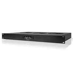
S-SERIES
STEP 1 You may cable manage the cords using tie mounts. wood screws. and zip ties included with this fan.
STEP 2 Plug the duct fan’s 4-pin molex connector into the universal controller’s left port signified by the fan/power symbol.
Secure the tie mounts onto a surface using the wood screws. Loop the zip ties around the cords into the tie mounts.
STEP 3 Plug the sensor probe into the controller’s 3.5mm jack. Set the probe near your plants in your grow tent for the most accurate reading.
STEP 4 Lastly. to power both the fan and controller. plug the fans power cord into an AC power outlet. (For EC Motor fans only)
POWERING AND SETUP T-SERIES
T-SERIES CONTROLLER Smart controllers for T-Series models with EC motors can support two fans of any size. The two EC-motor fans must be plugged in to an outlet to power the fans and the controller. See images below.
ADDING MORE FANS
The smart controller for the CLOUDLINE T-Series has an additional port so that you can add an S-Series fan to power and control two fans together.
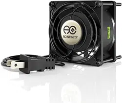
EC models have two cords with a molex connector and a three-pronged plug.
EC models can connect two fans
EC MOTOR Dual Connection
STEP 1 Remove the motor box from the mounting flange. Refer to steps 1 and 2 to learn how to remove the motor box. (Refer to steps 1 and 2 of the mounting installation section to learn how to remove the motor box).
STEP 2 Use a damp cloth to clear the impeller and fan blades of any dust and debris. Remove the wind circle in between the motor box and input flange.
STEP 3 Clear the stator blades of any dust and debris on the opposite end. Clean the area inside the output and exhaust flanges.
STEP 4 Secure the motor box onto the mounting flanges. Refer to step 7-9 to learn how to secure the motor box.
FAN SPEED ADJUSTING The controller features a single button that controls the fan speed from 0-8. Pressing the speed button increases the fan speed in one unit increments. Pressing the button at the 8 setting will set the fan speed back to 0.
POWERING ON/OFF Holding the speed button for 4 seconds will turn the fan OFF. Pressing it again from OFF will turn the fan ON at its last speed setting.
PROGRAMMING
Fan Speed Indicator
MODE BUTTON Cycles through the control ler's temperature/humidity programming: ON. OFF.
TIMER. AUTO (4 triggers). and ALARM (4 settings).
PROBE TEMP.
Displays the current tempera ture that the corded sensor probe is measuring. Shows “- -” if no probe is plugged in.
FAN SPEED Displays the current speed the fan is running at. or what speed it should be running at if no fans are plugged in.
ALERT ICONS Displays the alerts and statuses from the controller. including the alarm and the screen lock.
SETTING Displays the value you set for the current mode.
Pressing the up or down button changes the value.
PROBE HUMIDITY Displays the current humidity that the corded sensor probe is measuring. Shows “- -” if no probe is plugged in.
CONTROLLER MODE Displays the mode that the controller is currently in.
Pressing the mode button cycles through the modes.
LEAF BUTTON Turns the screen off while programs run in the background. Hold for two seconds to lock or unlock the LCD display.
UP / DOWN BUTTON Adjusts the settings of the mode that you are in. Up button raises and down button lowers. Hold both to turn off triggers.
PROGRAMMING
MODE SETTING Pressing the Mode button will cycle through the controller’s available programming modes and settings: ON Mode. OFF Mode. TIMER Mode. AUTO Mode (4 triggers). ALARM Settings (4 settings).
ON MODE In this mode. the fan will run continuously regardless of temperature or humidity. Use this mode to set the fan's maximum blowing strength. ranging from 0-10. when triggers are activated.
OFF MODE In this mode. the fan will not run regardless of temperature or humidity. Pushing the up or down button will change the display’s brightness. ranging in 1/2/3/A3. On setting A3. the display will dim its brightness down to 1 if the device is left unattended for 30 seconds. Holding the up or down button will change the display’s units to F or C. respectively.
TIMER MODE In this mode. pressing the up or down button will set the timer. The fan will ramp up to ON Mode’s setting until the timer’s clock runs out. It will begin spinning 5 seconds after the timer is set.
Leaving the timer mode while it’s running will pause it until you return to this mode.
PROGRAMMING
TRIGGER MODE: HIGH TEMPERATURE In this mode. pressing the up or down button sets the high temperature trigger. The fan will activate if the probe’s reading meets or exceeds this trigger.
It will gradually ramp up until it reaches the ON Mode’s setting. If the probe’s reading falls below your trigger. the fan will turn off. We recommend turning this trigger OFF when not in use during set up by holding the up and down buttons together.
You may set this trigger below the low temperature trigger to create a range where the fan is active.
TRIGGER MODE: LOW TEMPERATURE In this mode. pressing the up or down button sets the low temperature trigger. The fan will activate if the probe’s reading meets or falls below this trigger.
It will gradually ramp up until it reaches the ON Mode’s setting. If the probe’s reading rises above your trigger. the fan will turn off. We recommend turning this trigger OFF when not in use during set up by holding the up and down buttons together.
You may set this trigger above the high temperature trigger to create a range where the fan is active.
Note that this trigger can activate as long as you are in AUTO Mode. even if you are viewing a different trigger within AUTO Mode.
Note that this trigger can activate as long as you are in AUTO Mode. even if you are viewing a different trigger within AUTO Mode.
PROGRAMMING
TRIGGER MODE: HIGH HUMIDITY In this mode. pressing the up or down button sets a high humidity trigger. The fan will activate if the probe’s reading meets or exceeds this trigger.
It will gradually ramp up until it reaches the ON Mode’s setting. If the probe’s reading falls below your trigger. the fan will turn off. We recommend turning this trigger OFF when not in use during set up by holding the up and down buttons together.
You may set this trigger below the low humidity trigger to create a range where the fan is active.
TRIGGER MODE: LOW HUMIDITY In this mode. pressing the up or down button sets the low humidity trigger. The fan will activate if the probe’s reading meets or falls below the trigger.
It will gradually ramp up until it reaches the ON Mode’s setting. If the probe’s reading rises above your trigger. the fan will turn off. We recommend turning this trigger OFF when not in use during set up by holding the up and down buttons together.
You may set this trigger above the high humidity trigger to create a range where the fan is active.
Note that this trigger can activate as long as you are in AUTO Mode. even if you are viewing a different trigger within AUTO Mode.
Note that this trigger can activate as long as you are in AUTO Mode. even if you are viewing a different trigger within AUTO Mode.
PROGRAMMING
ALARM SETTING: HIGH TEMPERATURE In this mode. pressing the up and down button sets a high temperature alarm. The alarm will sound and its icon will flash if the probe’s read ing exceeds the set temperature.
To activate the alarm. leave the alarm mode.
The alarm will turn OFF if the probe’s reading falls below the trigger or if any button is pressed. You can also set the alarm OFF by holding the up and down buttons together.
You may set this alarm below the low tempera ture trigger to create an operating range.
Note that alarm triggers can only activate in AUTO. ON. or TIMER Mode. Please leave ALARM SETTING to arm the controller.
ALARM SETTING: LOW TEMPERATURE In this mode. pressing the up and down button sets a low temperature alarm. The alarm will sound and its icon will flash if the probe’s reading falls below the set temperature.
To activate the alarm. leave the alarm mode.
The alarm will turn OFF if the probe’s reading rises above the trigger or if any button is pressed. You can also set the alarm OFF by holding the up and down buttons together.
You may set this alarm above the high tempera ture trigger to create an operating range.
Note that alarm triggers can only activate in AUTO. ON. or TIMER Mode. Please leave ALARM SETTING to arm the controller.
Note that alarm triggers can only activate in AUTO. ON. or TIMER Mode. Please leave ALARM SETTING to arm the controller.
PROGRAMMING
ALARM SETTING: HIGH HUMIDITY In this mode. pressing the up and down button sets a high humidity alarm. The alarm will sound and its icon will flash if the probe’s reading exceeds the set humidity.
To activate the alarm. leave the alarm mode.
The alarm will turn OFF if the probe’s reading falls below the trigger or if any button is pressed. You can also set the alarm OFF by holding the up and down buttons together.
You may set this alarm below the low humidity trigger to create an operating range.
ALARM SETTING: LOW HUMIDITY In this mode. pressing the up and down button sets a low humidity alarm. The alarm will sound and its icon will flash if the probe’s reading falls below the set humidity.
To activate the alarm. leave the alarm mode.
The alarm will turn OFF if the probe’s reading rises above the trigger or if any button is pressed. You can also set the alarm OFF by holding the up and down buttons together.
You may set this alarm above the high humidity trigger to create an operating range.
Note that alarm triggers can only activate in AUTO. ON. or TIMER Mode. Please leave ALARM SETTING to arm the controller.
PROGRAMMING
DISPLAY BRIGHTNESS To adjust the brightness of the display. set the controller to OFF Mode. then press the up or down button to increase or decrease the brightness level. The brightness range is 1/2/3/A3.
FAHRENHEIT OR CELSIUS To switch between Fahrenheit and Celsius readings. set the controller to OFF Mode. Hold the up button to switch to Fahrenheit (°F) and the down button to switch to Celsius (°C).
ECO-MODE To turn off the LCD display. press the LEAF button. While the screen is off. all programs. settings. and alarms will run in the background. You can activate ECO Mode while the controller is locked. To exit ECO mode. press any button.
TEMPERATURE CALIBRATION To adjust the temperature that the probe sensor is measuring. press the MODE and UP button simultaneously. This can be done while the controller is any mode. The calibration cycle ranges from -8°F to 8°F (or -4°C to 4°C). You may use this setting to match the controller's temperature reading with your thermostat's reading.
HUMIDITY CALIBRATION To adjust the probe sensor’s humidity reading. press the MODE and DOWN button simultaneously.
This can be done in any mode. The calibration cycle ranges from -8% to 8%.
CONTROLLER LOCK To lock the controller and prevent accidental setting changes. hold the LEAF button for three or more seconds. While the display is locked. you will not be able to switch modes or adjust settings.
You will only be able to put the controller in ECO display. Holding the LEAF button for three or more seconds will unlock the controller.
PROGRAMMING
CHECK FAN ALERT This icon will flash when the fan's probe senses interference to its functioning.
Check the fan for possible issues. If the fan is not heating up. please see the warranty page for replacement information.
TEMPERATURE ALARM ALERT This icon will flash when the high or low temperature alarm has been triggered.
HUMIDITY ALARM ALERT This icon will flash when the high or low humidity alarm has been triggered.
DISPLAY LOCK ALERT This icon is visible when the controller has been locked. The icon will flash to alert you that the controller is locked if you try to change the mode or settings.
ALERT ICONS The top left of the display shows the alert icons. Icons may flash when the controller signals an alert to tell you a particular function or alarm is being triggered.
Q: I am missing my controller. It wasn't included in my package!
A: Please refer to page 7 for an image of what your controller should look like. Your controller should be neatly slotted in the box by this product manual.
Q: Where is the best place to position the sensor probe?
A: Place the sensor probe as close as possible to the hottest or most humid spot in your space.
Q: Do I need to remove the plastic cap from the probe?
A: Yes. You will need to remove the plastic cap so the probe can accurately read climate conditions.
Q: Can I mount this inline duct fan vertically?
A: Yes. The CLOUDLINE can be mounted in any orientation. including vertically.
Q: Will I be able to hardwire this fan to my own controller or thermostat?
A: We do not recommend hardwiring or splicing our fan's power wires. Such modifications may compromise electrical safety and will void this product's warranty.
Q: Do I need to use a power converter if I'm outside the US?
A: This product's voltage range is 100-240V AC. You may need a simple travel adapter to plug it into a foreign socket. or a power converter if your country uses a different voltage.
CLOUDLINE FAQ
Q: Does the controller retain its settings after power is shut off?
A: Yes. If the controller's power is cut off and is powered on afterwards. your settings will remain.
Q: What is the CFM of each of the different fan speeds?
A:Please contact customer support to request the CFM distribution of your CLOUDLINE model.
Q: I'm not getting enough airflow even after setting the fan speed to 10. What can I do?
A: Bends in ducting will reduce your fan's CFM performance. To retain airflow. you may straighten the ducting and eliminate as many bends as possible.
Q: Should I use this inline duct fan as an intake or an exhaust fan?
A: The CLOUDLINE is primarily used as an exhaust fan. but can be used as an intake fan as well.
You may use this fan as an intake fan if you need fresh air into your space.
Q: Can I connect different sized fans to the same controller?
A: Please refer to page 19 for details on daisy chaining fans together.
Register Booster Fans The AIRTAP series is a line of register booster fans designed to quietly increase airflow coming from your central heat and air conditioning systems. increasing comfort for your home. Features a thermal controller with intelligent programming that will automatically adjust airflow strength in response to heating and cooling temperatures you have set.
Shutter Fans The AIRLIFT series is a line of shutter exhaust fans designed to expel heat. moisture. odor. and dust from spaces like greenhouses. garages. attics. and sheds. It features an intelligent controller that includes temperature and humidity programming. adjustable fan speed controls. a timer. and an alarm system.
Crawlspace Fans The AIRTITAN is a line of weather-proof fans designed to provide ventilation. as well as odor and moisture control for crawl spaces and basements.
Discover the latest innovations in cooling and ventilation at acinfinity.com
If you have any issues with this product. contact us and we’ll happily resolve your problem or issue a full refund
This warranty program is our commitment to you. the product sold by AC Infinity will be free from defects in manufacturing for a period of two years from the date of purchase. If a product is found to have a defect in material or workmanship. we will take the appropriate actions defined in this warranty to resolve any issues.
The warranty program applies to any order. purchase. receipt. or use of any products sold by AC Infinity or our authorized dealerships. The program covers products that have become defective. malfunctioned. or expressively if the product becomes unusable. The warranty program goes into effect on the date of purchase. The program will expire two years from the date of purchase. If your product becomes defective during that period. AC Infinity will replace your product with a new one or issue you a full refund.
The warranty program does not cover abuse or misuse. This includes physical damage. submersion of the product in water. incorrect Installation such as wrong voltage input. and misuse for any reason other than intended purposes. AC Infinity is not responsible for consequential loss or incidental damages of any nature caused by the product. We will not warrant damage from normal wear such as scratches and dings.
To initiate a product warranty claim. please contact our customer service team at [email protected]
COPYRIGHT © 2021 AC INFINITY INC. ALL RIGHTS RESERVED No part of the materials including graphics or logos available in this booklet may be copied. photocopied. reproduced. translated or reduced to any electronic medium or machine readable form. in whole or in part. without specific permission from AC Infinity Inc.