EN
FR
PG
81
W415-1401 / C / 03.18.15
INSTALLER: LEAVE THIS MANUAL WITH THE APPLIANCE.
CONSUMER: RETAIN THIS MANUAL FOR FUTURE REFERENCE.
NEVER LEAVE CHILDREN OR OTHER AT RISK INDIVIDUALS ALONE WITH THE APPLIANCE
INSTALLATION AND
OPERATING INSTRUCTIONS
Wolf Steel Ltd., 24 Napoleon Rd., Barrie, ON, L4M 0G8 Canada /
103 Miller Drive, Crittenden, Kentucky, USA, 41030
Phone (705)721-1212 • Fax (705)722-6031 • www.napoleonfi replaces.com • [email protected]
1.28F
$10.00
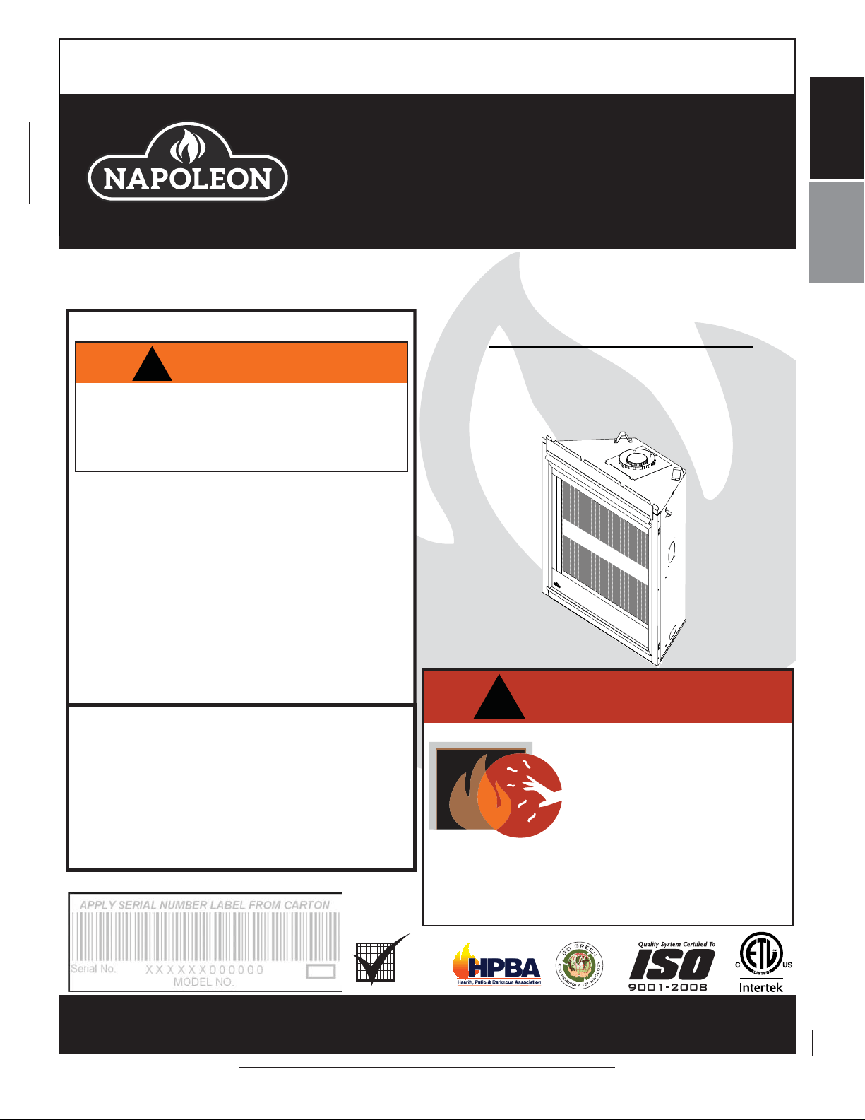
HOT GLASS WILL CAUSE
BURNS.
DO NOT TOUCH GLASS UNTIL
COOLED.
NEVER ALLOW CHILDREN TO
TOUCH GLASS.
!
DANGER
A barrier designed to reduce the risk of burns from
the hot viewing glass is provided with this appliance
and shall be installed for the protection of children
and other at-risk individuals.
SAFETY INFORMATION
!
WARNING
- Do not store or use gasoline or other fl ammable
vapors and liquids in the vicinity of this or any
other appliance.
- WHAT TO DO IF YOU SMELL GAS:
• Do not try to light any appliance.
• Do not touch any electrical switch; do not use
any phone in your building.
• Immediately call your gas supplier from a
neighbour’s phone. Follow the gas supplier’s
instructions.
• If you cannot reach your gas supplier, call the
fi re department.
- Installation and service must be performed by a
qualifi ed installer, service agency or the supplier.
This appliance may be installed in an aftermarket,
permanently located, manufactured home (USA
only) or mobile home, where not prohibited by
local codes.
This appliance is only for use with the type of gas
indicated on the rating plate. This appliance is
not convertible for use with other gases, unless a
certifi ed kit is used.
If the information in these instructions
are not followed exactly, a fi re or
explosion may result causing property
damage, personal injury or loss of life.
CERTIFIED FOR CANADA AND UNITED STATES USING ANSI/CSA METHODS.
Decorative Product: Not for use as a heating appliance.
BARRIER
CONFORMS TO AMERICAN NATIONAL STANDARDS: ANSI Z21.50, CERTIFIED TO CANADIAN CSA 2.22 FOR VENTED GAS FIREPLACES.
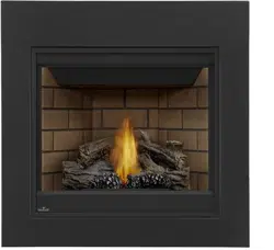
B36NT / B36NTE &
GX36NT / GX36NTE
NATURAL GAS MODEL
B36 ILLUSTRATED
SAFETY BARRIER
B36PT / B36PTE &
GX36PT / GX36PTE
PROPANE GAS MODEL

2
W415-1401 / C / 03.18.15
EN
TABLE OF CONTENTS
1.0 INSTALLATION OVERVIEW 3
2.0 INTRODUCTION 4
2.1 B36 / GX36 DIMENSIONS 5
2.2 GENERAL INSTRUCTIONS 6
2.3 GENERAL INFORMATION 7
2.4 RATING PLATE INFORMATION 8
3.0 VENTING 9
3.1 VENTING LENGTHS AND COMPONENTS 10
3.2 TYPICAL VENT INSTALLATION 11
3.3 SPECIAL VENT INSTALLATIONS 13
3.3.1 PERISCOPE TERMINATION 13
3.3.2 CORNER TERMINATION 13
3.4 MINIMUM AIR TERMINAL LOCATION CLEARANCES 14
3.5 VENTING APPLICATION FLOW CHART 15
3.6 DEFINITIONS 16
3.7 ELBOW VENT LENGTH VALUES 16
3.8 TOP EXIT HORIZONTAL TERMINATION 17
3.9 REAR EXIT HORIZONTAL TERMINATION 19
3.10 TOP OR REAR EXIT VERTICAL TERMINATION 21
3.11 REAR EXIT 23
3.12 TOP EXIT 24
4.0 INSTALLATION 25
4.1 WALL AND CEILING PROTECTION 25
4.1.1 HORIZONTAL INSTALLATION 26
4.1.2 VERTICAL INSTALLATION 26
4.2 USING FLEXIBLE VENT COMPONENTS 27
4.2.1 HORIZONTAL AIR TERMINAL INSTALLATION 27
4.2.2 VERTICAL AIR TERMINAL INSTALLATION 28
4.2.3 APPLIANCE VENT CONNECTION 29
4.3 USING RIGID VENT COMPONENTS 29
4.3.1 HORIZONTAL AIR TERMINAL INSTALLATION 29
4.3.2 VERTICAL AIR TERMINAL INSTALLATION 30
4.4 RESTRICTING VERTICAL VENTS 30
4.5 VERTICAL THROUGH EXISTING CHIMNEY 31
4.6 MOBILE HOME INSTALLATION 32
4.7 GAS INSTALLATION 33
4.8 OPTIONAL WALL SWITCH 33
5.0 FRAMING 34
5.1 B36 FRAMING 34
5.1.1 MINIMUM FRAMING DIMENSIONS B36 35
5.2 MINIMUM ENCLOSURE CLEARANCES 37
5.3 GX36 FRAMING 41
5.3.1 MINIMUM FRAMING DIMENSIONS GX36 42
5.4 ALCOVE CLEARANCES 48
5.5 NON-COMBUSTIBLE FACING MATERIAL 49
5.6 MINIMUM MANTEL CLEARANCES 50
5.7 NAILING TAB INSTALLATION 50
6.0 FINISHING 51
6.1 SAFETY SCREEN & DOOR REMOVAL / INSTALLATION 51
6.2 LOG PLACEMENT 52
6.3 LOGO PLACEMENT 53
6.4 BATTERY BACK-UP INSTALLATION 53
6.5 BLOWER INSTALLATION 54
6.6 WIRING DIAGRAM (ELECTRONIC) 55
7.0 OPERATION 56
7.1 B36NTRE/GX36NTRE & B36PTRE/GX36PTRE (ELECTRONIC) 56
8.0 OPERATION 57
8.1 B36NTR/GX36NTR & B36PTR/GX36PTR (MILLIVOLT) 57
9.0 ADJUSTMENT 58
9.1 PILOT BURNER ADJUSTMENT 58
9.2 VENTURI ADJUSTMENT 58
9.3 FLAME CHARACTERISTICS 59
10.0 MAINTENANCE 59
10.2 DOOR GLASS REPLACEMENT 60
10.1 ANNUAL MAINTENANCE 60
10.3 CARE OF GLASS 61
11.0 REPLACEMENTS 61
12.0 B36 OVERVIEW 62
13.0 B36 ELECTRONIC VALVE TRAIN ASSEMBLY 63
14.0 B36 MILLIVOLT VALVE TRAIN ASSEMBLY 64
15.0 B36 ACCESSORIES 65
16.0 GX36 OVERVIEW 66
NOTE: The camera icon indicates video tutorials are available as additional reference, visit
http://www.napoleonfi replaces.com/category/product-support/support-centre/
NOTE: Changes, other than editorial, are denoted by a vertical line in the margin.
3
W415-1401 / C / 03.18.15
EN
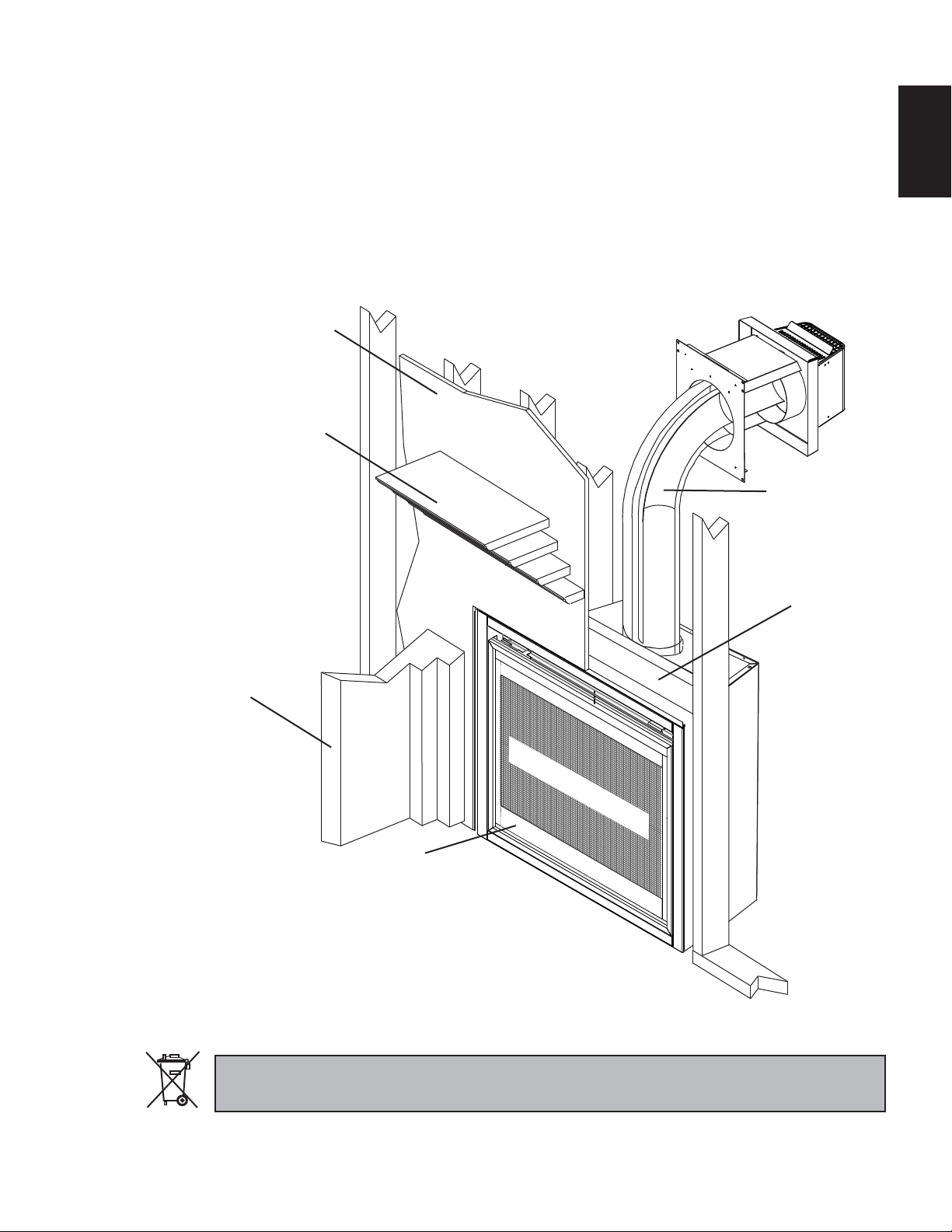
1.0 INSTALLATION OVERVIEW
See the section “MINIMUM
ENCLOSURE CLEARANCES”
for drywall (or other combus-
tible material).
See the section “MINIMUM
MANTEL CLEARANCES”.
See the section
“NON-COMBUSTIBLE
FINISHING”.
Side
Wall
See the section
“FRAMING”.
See the section
“VENTING” and
“INSTALLATION”.
See the section
“RATING PLATE
INFORMATION”.
SAFETY BARRIER
B36 ILLUSTRATED
Batteries must be disposed of according to the local laws and regulations. Some batteries may be recycled,
and may be accepted for disposal at your local recycling center. Check with your municipality for recycling
instructions.
17.0 GX36 MILLIVOLT VALVE TRAIN ASSEMBLY 67
18.0 GX36 ELECTRONIC VALVE TRAIN ASSEMBLY 68
19.0 GX36 ACCESSORIES 69
20.0 TROUBLESHOOTING (ELECTRONIC) 71
21.0 TROUBLESHOOTING (MILLIVOLT) 74
22.0 WARRANTY 77
23.0 SERVICE HISTORY 78
24.0 NOTES 79

4
W415-1401 / C / 03.18.15
EN
2.0 INTRODUCTION
3.1D
!
WARNING
• THIS APPLIANCE IS HOT WHEN OPERATED AND CAN CAUSE SEVERE BURNS IF CONTACTED.
• ANY CHANGES TO THIS APPLIANCE OR IT’S CONTROLS CAN BE DANGEROUS AND IS PROHIBITED.
• Do not operate appliance before reading and understanding operating instructions. Failure to operate appliance according to
operating instructions could cause fi re or injury.
• Risk of fi re or asphyxiation do not operate appliance with fi xed glass removed.
• Do not connect 110 volts to the control valve.
• Risk of burns. The appliance should be turned off and cooled before servicing.
• Do not install damaged, incomplete or substitute components.
• Risk of cuts and abrasions. Wear protective gloves and safety glasses during installation. Sheet metal edges may be sharp.
• Do not burn wood or other materials in this appliance.
• Children and adults should be alerted to the hazards of high surface temperature and should stay away to avoid burns
or clothing ignition.
• Young children should be carefully supervised when they are in the same room as the appliance.
Toddlers, young children and others may be susceptible to accidental contact burns. A physical barrier is
recommended if there are at risk individuals in the house. To restrict access to an appliance or stove, install an
adjustable safety gate to keep toddlers, young children and other at risk individuals out of the room and away from hot
surfaces.
• Clothing or other fl ammable material should not be placed on or near the appliance.
• Due to high temperatures, the appliance should be located out of traffi c and away from furniture and draperies.
• Ensure you have incorporated adequate safety measure to protect infants/toddlers from touching hot surfaces.
• Even after the appliance is out, the glass and/or screen will remain hot for an extended period of time.
• Check with your local hearth specialty dealer for safety screens and hearth guards to protect children from hot surfaces. These
screens and guards must be fastened to the fl oor.
• Any safety screen, guard or barrier removed for servicing the appliance, must be replaced prior to operating the
appliance.
• The appliance is a vented gas-fi red appliance. Do not burn wood or other materials in the appliance.
• The appliance area must be kept clear and free from combustible materials, gasoline and other fl ammable vapors and liquids.
• Under no circumstances should this appliance be modifi ed.
• This appliance must not be connected to a chimney fl ue pipe serving a separate solid fuel burning appliance.
• Do not use this appliance if any part has been under water. Immediately call a qualifi ed service technician to inspect the appliance
and to replace any part of the control system and any gas control which has been under water.
• Do not operate the appliance with the glass door removed, cracked or broken. Replacement of the glass should be done by a
licensed or qualifi ed service person.
• Do not strike or slam shut the appliance glass door.
• When equipped with pressure relief doors, they must be kept closed while the appliance is operating to prevent exhaust fumes
containing carbon monoxide, from entering into the home. Temperatures of the exhaust escaping through these openings can also
cause the surrounding combustible materials to overheat and catch fi re.Only doors / optional fronts certifi ed with the unit are to be
installed on the appliance.
• Only doors / optional fronts certifi ed with the unit are to be installed on the appliance.
• Keep the packaging material out of reach of children and dispose of the material in a safe manner. As with all plastic bags, these
are not toys and should be kept away from children and infants.
• As with any combustion appliance, we recommend having your appliance regularly inspected and serviced as well as having a
Carbon Monoxide Detector installed in the same area to defend you and your family against Carbon Monoxide.
• Ensure clearances to combustibles are maintained when building a mantel or shelves above the appliance. Elevated temperatures
on the wall or in the air above the appliance can cause melting, discolouration or damage to decorations, a T.V. or other electronic
components.
• A barrier designed to reduce the risk of burns from the hot viewing glass is provided with this appliance and shall be
installed.
• If the barrier becomes damaged, the barrier shall be replaced with the manufacturer’s barrier for this appliance.
• Installation and repair should be done by a qualifi ed service person. The appliance should be inspected before use and
at least annually by a professional service person. More frequent cleaning may be required due to excessive lint from
carpeting, bedding material, etc. It is imperative that control compartments, burners and circulating air passageways of
the appliance be kept clean.
• This appliance uses and requires a fast acting thermocouple. Replace only with a fast acting thermocouple supplied by Wolf Steel
Ltd.
5
W415-1401 / C / 03.18.15
EN
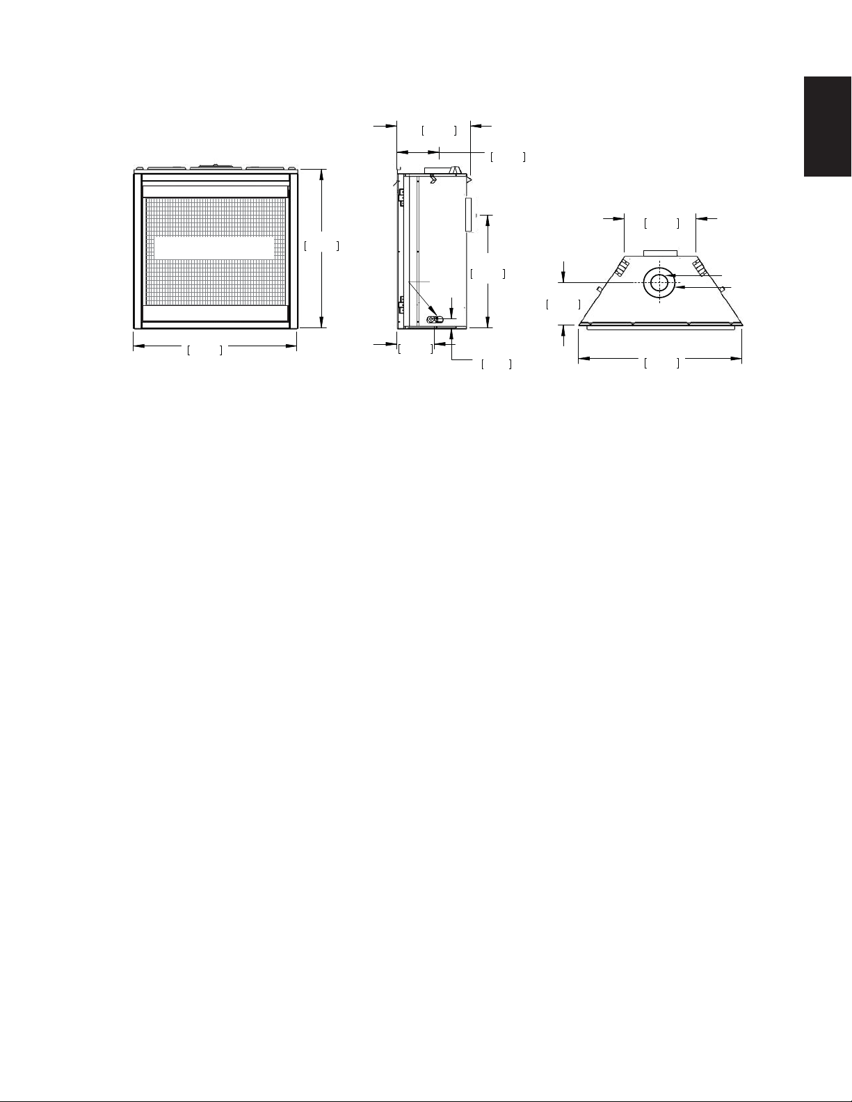
2.1 B36 / GX36 DIMENSIONS
34 1/16"
866mm
35"
890mm
15 3/4"
400mm
24"
610mm
9 1/16"
230mm
8"
203mm
1 15/16"
49mm
GAS
INLET
15 3/8"
391mm
35"
889mm
9 1/16"
230mm
SAFETY BARRIER
4" [102mm]
7" [178mm]
6
W415-1401 / C / 03.18.15
EN
2.2 GENERAL INSTRUCTIONS
4.1B
THIS GAS APPLIANCE SHOULD BE INSTALLED AND SERVICED BY A QUALIFIED INSTALLER to
conform with local codes. Installation practices vary from region to region and it is important to know the
specifi cs that apply to your area, for example in Massachusetts State:
• This product must be installed by a licensed plumber or gas fi tter when installed within the commonwealth
of Massachusetts.
• The appliance damper must be removed or welded in the open position prior to installation of an appliance
insert or gas log.
• The appliance off valve must be a “T” handle gas cock.
• The fl exible connector must not be longer than 36 inches (914mm).
• A Carbon Monoxide detector is required in all rooms containing gas fi red appliances.
• The appliance is not approved for installation in a bedroom or bathroom unless the unit is a direct vent
sealed combustion product.
The installation must conform with local codes or, in
absence of local codes, the National Gas and Propane
Installation Code CSA B149.1 in Canada, or the National
Fuel Gas Code, ANSI Z223.1 / NFPA 54 in the United
States. Suitable for mobile home installation if installed in
accordance with the current standard CAN/CSA Z240MH
Series, for gas equipped mobile homes, in Canada or
A
NSI Z223.1 and NFPA 54 in the United States.
A
s long as the required clearance to combustibles is
maintained, the most desirable and benefi cial location
for an appliance is in the center of a building, thereby
allowing the most effi cient use of the heat created. The location of windows, doors and the traffi c fl ow in the
room where the appliance is to be located should be considered. If possible, you should choose a location
where the vent will pass through the house without cutting a fl oor or roof joist.
If the appliance is installed directly on carpeting, vinyl tile or other combustible material other than wood
fl ooring, the appliance shall be installed on a metal or wood panel extending the full width and depth.
Some appliances have optional fans or blowers. If an optional fan or blower is installed, the junction box must
be electrically connected and grounded in accordance with local codes, use the current CSA C22.1 Canadian
Electrical Code in Canada or the ANSI/NFPA 70 National Electrical code in the United States.
We suggest that our gas
hearth products be installed
and serviced by professionals
who are certied in the U.S.
by the National Fireplace
Institute
®
(NFI) as NFI Gas
Specialists
www.ncertied.org
ALWAYS LIGHT THE PILOT WHETHER FOR THE FIRST TIME OR IF THE GAS SUPPLY HAS RUN OUT,
WITH THE GLASS DOOR OPENED OR REMOVED.
PROVIDE ADEQUATE CLEARANCE FOR SERVICING AND OPERATING THE APPLIANCE.
PROVIDE ADEQUATE VENTILATION.
NEVER OBSTRUCT THE FRONT OPENING OF THE APPLIANCE.
OBJECTS PLACED IN FRONT OF THE APPLIANCE MUST BE KEPT A MINIMUM OF 48” (1219mm) FROM
THE FRONT FACE OF THE APPLIANCE.
SURFACES AROUND AND ESPECIALLY ABOVE THE APPLIANCE CAN BECOME HOT. AVOID CONTACT
WHEN THE APPLIANCE IS OPERATING.
FIRE RISK. EXPLOSION HAZARD.
HIGH PRESSURE WILL DAMAGE VALVE. DISCONNECT GAS SUPPLY PIPING BEFORE PRESSURE TESTING GAS
LINE AT TEST PRESSURES ABOVE 1/2 PSIG. CLOSE THE MANUAL SHUT-OFF VALVE BEFORE PRESSURE
TESTING GAS LINE AT TEST PRESSURES EQUAL TO OR LESS THAN 1/2 PSIG (35 mb).
USE ONLY WOLF STEEL APPROVED OPTIONAL ACCESSORIES AND REPLACEMENT PARTS WITH THIS APPLIANCE.
USING NON-LISTED ACCESSORIES (BLOWERS, DOORS, LOUVRES, TRIMS, GAS COMPONENTS, VENTING
COMPONENTS, ETC.) COULD RESULT IN A SAFETY HAZARD AND WILL VOID THE WARRANTY AND CERTIFICATION.
!
WARNING
7
W415-1401 / C / 03.18.15
EN
2.3 GENERAL INFORMATION
FOR YOUR SATISFACTION, THIS APPLIANCE HAS BEEN TEST-FIRED TO ASSURE ITS OPERATION AND
QUALITY!
This appliance is approved for bathroom, bedroom and bed-sitting room installations and is suitable for mobile
home installation.
No external electricity (110 volts or 24 volts) is required for the gas millivolt system operation.
Expansion / contraction noises during heating up and cooling down cycles are normal and are to be
expected.
A barrier designed to reduce the risk of burns from the hot viewing glass is provided with the
appliance and must be installed.
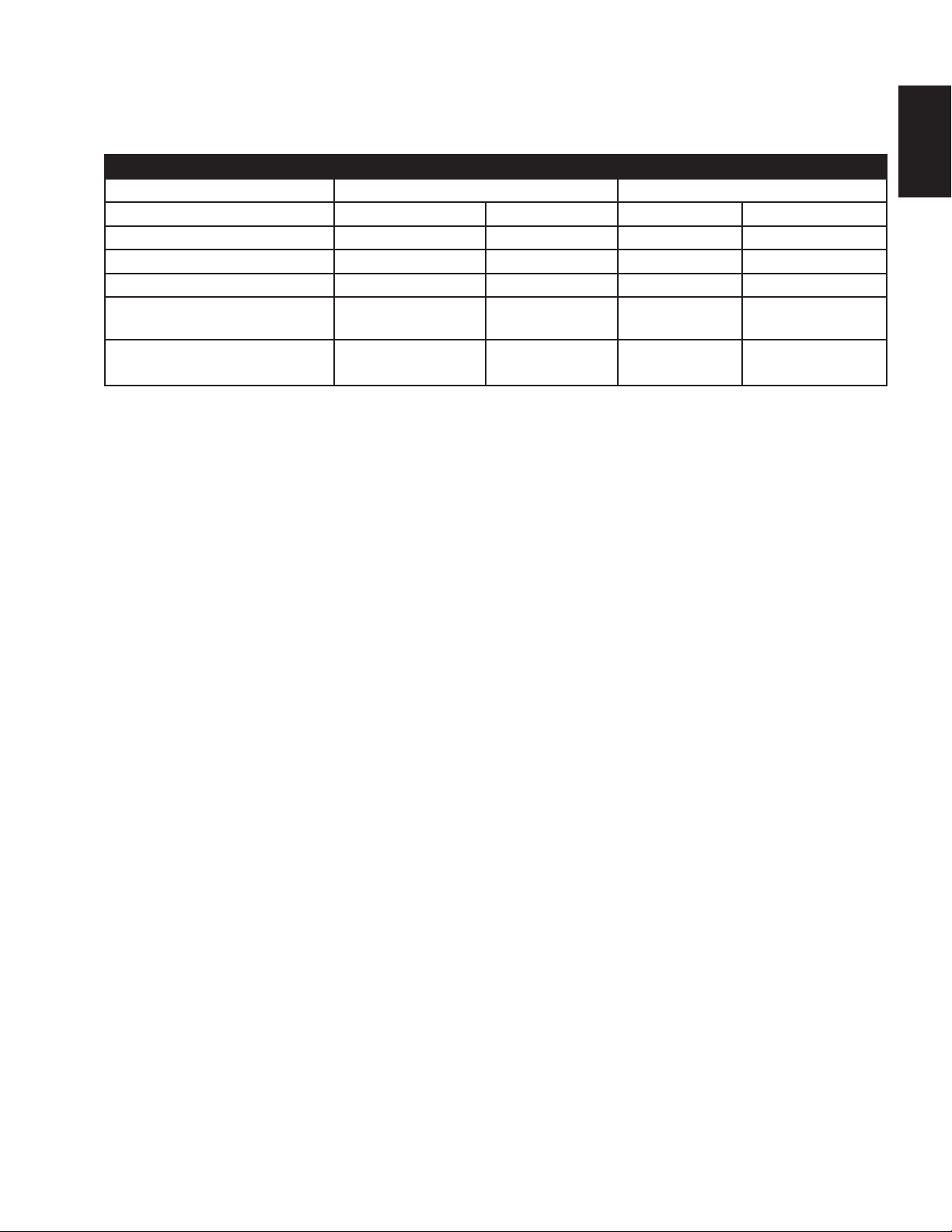
RATES AND EFFICIENCIES
B36 GX36
NG LP NG LP
Altitude (FT) 0-4,500 0-4500 0-4,500 0-4500
Max. Input (BTU/HR) 18,000 18,000 26,000 26,000
Min. Inlet Gas Supply Pressure 4.5" (11mb) w.c. 11" (27mb) w.c. 4.5" (11mb) w.c. 11" (27mb) w.c.
Max. Inlet Gas Supply
Pressure
7" (17mb) w.c. 13" (32mb) w.c. 7" (17mb) w.c. 13" (32mb) w.c.
Manifold Pressure (Under Flow
Conditions)
3.5" (9mb) w.c. 10" (25mb) w.c. 3.5" (9mb) w.c. 10" (25mb) w.c.
8
W415-1401 / C / 03.18.15
EN
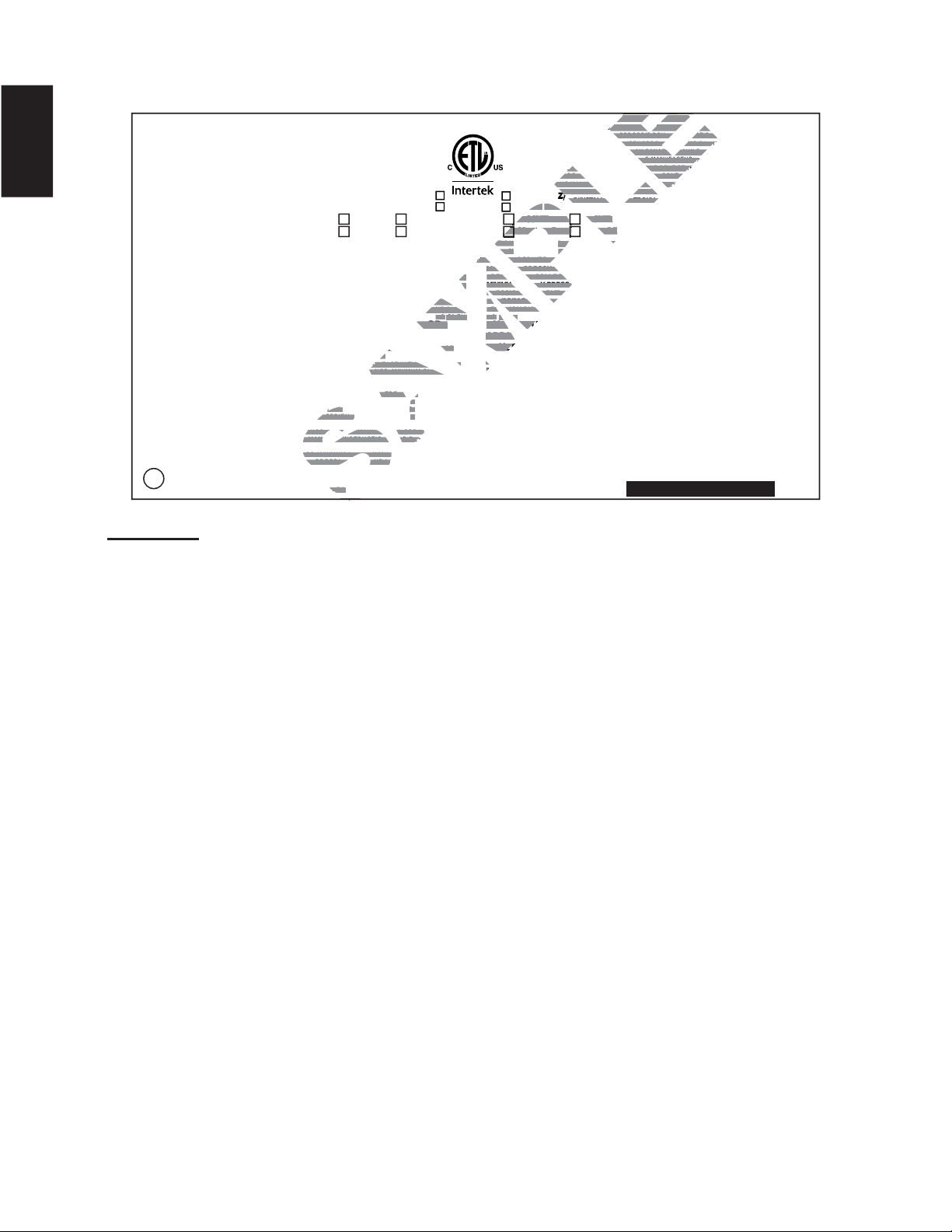
2.4 RATING PLATE INFORMATION
W385-1987
FOYER À GAZ VENTILÉ DIRECT. HOMOLOGUE POUR INSTALLATION DANS UNE CHAMBRE A COUCHER,
UNE SALLE DE BAIN ET UN STUDIO. APPROPRIE POUR INSTALLATION DANS UNE MAISON MOBILE SI
SON INSTALLATION CONFORME AUX EXIGENCES DE LA NORME CAN/CSA Z240MH SERIE DE MAISONS
MOBILES EQUIPEES AU GAZ, EN VIGUEUR AU CANADA OU AUX ETATS-UNIS DE LA NORME DE
SECURITE ET DE CONSTRUCTION DE MAISONS MANUFACTUREES, TITRE 24 CFR, SECTION 3280.
DANS LE CAS OU CETTE NORME D'ETATS-UNIS NE PEUT ETRE APPLIQUEE, SE REFERER A LA NORME
RELATIVE AU CRITERE DE MESURES DE SECURITE CONTRE L'INCENDIE POUR LES INSTALLATIONS
DANS LES MAISONS MANUFACTURES, LES SITES ET LES COMMUNAUTES, ANSI/NFPA 501A.
POUR
UNE UTILISER AVEC BARRIÈRE W565-0144. SUIVEZ LES INSTRUCTIONS
D'INSTALLATION SE TROUVENT DANS LE MANUEL D'INSTALLATION
DIRECT VENT GAS FIREPLACE. SUITABLE FOR BEDROOM, BATHROOM AND BED-SITTING ROOM
INSTALLATION. SUITABLE FOR MOBILE HOME INSTALLATION IF INSTALLED IN ACCORDANCE
WITH THE CURRENT STANDARD CAN/CSA Z240MH SERIES GAS EQUIPPED MOBILE HOMES,
IN CANADA OR IN THE UNITED STATES THE MANUFACTURED HOME CONTRUCTION AND
SAFETY STANDARD, TITLE 24 CFR, PART 3280. WHEN THIS US STANDARD IS NOT
APPLICABLE USE THE STANDARD FOR FIRE SAFETY CRITERIA FOR MANUFACTURED
HOME INSTALLATIONS, SITES AND COMMUNITIES, ANSI / NFPA 501A.
FOR USE WITH BARRIER
W565-0144. FOLLOW THE INSTALLATION INSTRUCTIONS LOCATED IN THE INSTALLATION MANUAL.
9700539 (WSL) 4001657 (NGZ)
4001658 (NAC) 4001659 (WUSA)
0-4500FT (0-1370m) ALTITUDE / ELEVATION 0-4500FT (0-1370m)
18,000 BTU/h INPUT / ALIMENTATION 18,000 BTU/h
13,000 BTU/h REDUCED INPUT / ALIMENTATION REDUITE 13,500 BTU/h
MANIFOLD PRESSURE: 3.5" (9MB) WATER COLUMN MANIFOLD PRESSURE: 10" (25MB) WATER COLUMN
PRESSION AU COLLECTEUR: 3.5" (9 MB) D'UNE COLONNE D'EAU PRESSION AU COLLECTEUR: 10" (25MB) D'UNE COLONNE D'EAU
MINIMUM SUPPLY PRESSURE: 4.5" (11MB) WATER COLUMN MINIMUM SUPPLY PRESSURE: 11" (27MB) WATER COLUMN
PRESSION D'ALIMENTATION MINIMALE: 4.5" (11MB) D'UNE COLONNE D'EAU PRESSION D'ALIMENTATION MINIMALE: 11" (27MB) D'UNE COLONNE D'EAU
MAXIMUM SUPPLY PRESSURE: 7.0" (17MB) WATER COLUMN MAXIMUM SUPPLY PRESSURE: 13" (32MB) WATER COLUMN
PRESSION D'ALIMENTATION MAXIMALE: 7.0" (17MB) D'UNE COLONNE D'EAU PRESSION D'ALIMENTATION MAXIMALE: 13" (32MB) D'UNE COLONNE D'EAU
P4: 51.7% P4: 51.7%
NOT FOR USE WITH SOLID FUEL. FOR USE WITH GLASS DOORS
CERTIFIED WITH THIS UNIT ONLY.
WARNING:
THIS FIREPLACE USES AND REQUIRES A FAST ACTING THERMOCOUPLE. REPLACE
ONLY WITH A FAST ACTING THERMOCOUPLE SUPPLIED BY WOLF STEEL LTD.
DO NOT ADD ANY MATERIAL TO THE APPLIANCE, WHICH WILL COME IN CONTACT WITH THE FLAMES,
OTHER THAN THAT SUPPLIED BY THE MANUFACTURER WITH THE APPLIANCE. MINIMUM CLEARANCE
TO COMBUSTIBLE MATERIALS /
DEGAGEMENTS MINIMAUX DES MATERIAUX COMBUSTIBLES:
TOP/ DESSUS 0 RECESSED DEPTH / PROFONDEUR D'ENCASTRE 16"
FLOOR / PLANCHER 0 VENT SIDES / COTES DE L'EVENT 1"
SIDES / COTES 0 VENT TOP / EVENT SUPERIEUR 3"
BACK / ARRIERE 0 VENT BOTTOM / EVENT INFERIEUR 1"
MANTEL / MANTEAU 2" *
* MAXIMUM HORIZONTAL EXTENSION / L'EXTENSION HORIZONTALE MAXIMALE: 2". SEE INSTRUCTION
MANUAL FOR GREATER EXTENSIONS. REFERER AU MANUEL D'INSTRUCTION POUR DES
EXTENSIONS PLUS GRANDES.
SEE OWNER'S INSTRUCTION MANUAL FOR MINIMUM AND MAXIMUM VENT LENGTHS.
REFERER AU MANUEL D'INSTALLATION DE PROPRIETAIRE POUR LES LONGUEURS
D'EVACUATION MINIMALE ET MAXIMALE.
WOLF STEEL LTD.
24 NAPOLEON ROAD, BARRIE, ON, L4M 0G8 CANADA
UN COMBUSTIBLE SOLIDE NE DOIT PAS ETRE UTILISE AVEC CET
APPAREIL. UTILISER AVEC LES PORTES VITREES HOMOLOGUEES
SEULEMENT AVEC CETTE UNITE.
AVERTISSEMENT: CE FOYER UTILISE ET REQUIERT UN THERMOCOUPLE À ACTION RAPIDE.
REMPLACEZ UNIQUEMENT AVEC UN THERMOCOUPLE À ACTION RAPIDE DE WOLF STEEL LTÉE.
N’AJOUTEZ PAS A CET APPAREIL AUCUN MATERIAU DEVANT ENTRER EN CONTACT AVEC LES FLAMMES
AUTRE QUE CELUI QUI EST FOURNI AVEC CET APPAREIL PAR LE FABRICANT.
THE APPLIANCE MUST BE VENTED USING THE APPROPRIATE WOLF STEEL VENT KITS. SEE OWNERS
INSTALLATION MANUAL FOR VENTING SPECIFICS. PROPER REINSTALLATION AND RESEALING IS
NECESSARY AFTER SERVICING THE VENT-AIR INTAKE SYSTEM.
L'APPAREIL DOIT EVACUER SES GAZ EN UTILISANT L'ENSEMBLE D'EVACUATION PROPRE A NAPOLEON.
REFERER AU MANUEL D'INSTALLATION DE PROPRIETAIRE POUR L'EVACUATION PRECISE. IL EST
IMPORTANT DE BIEN REINSTALLER ET RESCELLER L'EVENT APRES AVOIR ASSURE LE MAINTIEN DU
SYSTEME DE PRISE D'AIR.
DECORATIVE PRODUCT: NOT FOR USE AS A HEATING APPLIANCE
PRODUIT DÉCORATIF: NE PAS UTILISER COMME APPPAREIL DE CHAUFFAGE.
ELECTRICAL RATING / CLASSIFICATION: 115V 0.82AMP, 60HZ
OPTIONAL FAN KIT / ENSEMBLE DE VENTILATEUR FACULTATIF: EP35
SERIAL NUMBER/NO. DE SERIE:
B36
B36NTR CB36NTR MODEL CB36PTR B36PTR
B36NTRE CB36NTRE CB36PTRE B36PTRE
CONFORMS TO / CONFORME AUX: ANSI Z21.50-2014, CERTIFIED TO / CERTIFIE CSA 2.22-2014 VENTED GAS FIREPLACE / FOYER À GAZ VENTILÉ.
INSTALLER: It is your responsibility to check off the appropriate box on the rating plate according to
the model, venting and gas type of the appliance.
For rating plate location, see “INSTALLATION OVERVIEW” section.
This illustration is for reference only. Refer to the rating plate on the appliance for accurate information.
NOTE: The rating plate must remain with the appliance at all times. It must not be removed.
SAMPLE
HOMOLOGUE POUR INSTALLATION DOMOLOGUE POUR INSTALLATION D
UDIO. APPROPRIE POUR INSTALLATION D. APPROPRIE POUR INSTALLATION D
RME AUX EXIGENCES DE LA NORME CAN/CEXIGENCES DE LA NORME CAN/C
GAZ, EN VIGUEUR AU CANADA OU AUX ETATR AU CANADA OU AUX ETAT
NSTRUCTION DE MAISONS MANUFACTUREEONS MANUFACTUREE
CETTE NORME D'ETATS-UNIS NE PEUT ETREETTE NORME D'ETATS-UNIS NE PEUT ETRE
RITERE DE MESURES DE SECURITE CONTRETERE DE MESURES DE SECURITE CONTR
AISONS MANUFACTURES, LES SITES ET LESSONS MANUFACTURES, LES SITES ET LES
UNE UTILISER AVEC BARRIÈRE W5 UNE UTILISER AVEC BARRIÈR
D'INSTALLATION SE TROUVEN D'INSTALLATION SE TROUVE
57 (NGZ))
1659 659
(WUSA)(WUS
VATION ATION
0-4500FT (0-1370m0-4500FT (0-1370m
ENTATION TION
18,000 BTU/
h18
LIMENTATION REDUITE 13,500 BTU/hIMENTATION REDUITE
N
M
ANIFOLD PRESSURE:
MANIFOLD PRESSURE
10" (25M
EAU AU
PRESSION AU COLLECTEUR: PRESSION AU COLLECTE
LUMN MN
MINIMUM SUPPLY PRESSURMINIMUM SUPPLY PRESSU
NE D'EAUU
PRESSION D'ALIMENTATIPRESSION D'ALIMENTAT
R COLUMN R COLU
MAXIMUM SUPPLY PREMAXIMUM SUPPLY PR
LONNE D'EAU ONNE D'EAU
PRESSION D'ALIMENPRESSION D'ALI
P
4
:P4:
51.7
% 51.7%
P
4:
P4:
5
1.7
%51.7%
S DOORSDOORS
MOCOUPLE. REPLACE OCOUPLE. REPLACE
TD.D.
CONTACT WITH THE FLAMES, CONTACT WITH THE FLAMES,
PLIANCE. MINIMUM CLEARANCEIANCE. MINIMUM CLEAR
DEUR D'ENCASTRE 16"ASTRE 16"
VENT
1
"1"
RIEUR RIEUR
3"3"
T INFERIEURT INFERIEUR
1
"1"
ON HORIZONTALE MAXIMALE: 2". SEE INSN HORIZONTALE MAXIMALE: 2". SEE IN
R AU MANUEL D'INSTRUCTION POUR DES
U MANUEL D'INSTRUCTION POUR DES
AL FOR MINIMUM AND MAXIMUM VEN
FOR MINIMUM AND MAXIMUM
N DE PROPRIETAIRE POUR LES
DE PROPRIETAIRE POUR LE
NADANADA
UN COMBUUN COMBU
APPAREIAPPAR
SEULESEULE
AVEA
RR
E
SAMPLE
CB36PTR B36PTR CB36PTR B36PTR
PL
P
PL
P
CB36PTRE B36PTRE CB36PTRE B36PTRE
ACE / FOYER À GAZ VENTILACE / FOYER À GAZ VEN

9
W415-1401 / C / 03.18.15
EN
3.0 VENTING
7.1C
THIS APPLIANCE USES A 4” (102mm) EXHAUST / 7” (178mm) AIR INTAKE VENT PIPE SYSTEM.
Refer to the section applicable to your installation.
For safe and proper operation of the appliance follow the venting instruction exactly. Deviation from the
minimum vertical vent length can create diffi culty in burner start-up and/or carboning. Under extreme
vent confi gurations, allow several minutes (5-15) for the fl ame to stabilize after ignition. Although not a
requirement, it is recommended for vent lengths that pass through unheated spaces (attics, garages, crawl
spaces) be insulated with the insulation wrapped in a protective sleeve to minimize condensation. Provide
a means for visually checking the vent connection to the appliance after the appliance is installed. Use a
fi restop, vent pipe shield or attic insulation shield when penetrating interior walls, fl oor or ceiling.
NOTE: If for any reason the vent air intake system is disassembled; reinstall per the instructions
provided for the initial installation.
!
WARNING
RISK OF FIRE, MAINTAIN SPECIFIED AIR SPACE CLEARANCES TO VENT PIPE AND APPLIANCE.
IF VENTING IS INCLUDED WITH SPACERS THE VENT SYSTEM MUST BE SUPPORTED EVERY 3FT
(0.9m) FOR BOTH VERTICAL AND HORIZONTAL RUNS. USE SUPPORTS OR EQUIVALENT
NON-COMBUSTIBLE STRAPPING TO MAINTAIN THE REQUIRED CLEARANCE FROM
COMBUSTIBLES. USE WOLF STEEL LTD. SUPPORT RING ASSEMBLY W010-0370 OR EQUIVALENT
NON-COMBUSTIBLE STRAPPING TO MAINTAIN THE MINIMUM CLEARANCE TO COMBUSTIBLES
FOR BOTH VERTICAL AND HORIZONTAL RUNS. SPACERS ARE ATTACHED TO THE INNER PIPE AT
PREDETERMINED INTERVALS TO MAINTAIN AN EVEN AIR GAP TO THE OUTER PIPE. THIS GAP IS
REQUIRED FOR SAFE OPERATION. A SPACER IS REQUIRED AT THE START, MIDDLE AND END OF
EACH ELBOW TO ENSURE THIS GAP IS MAINTAINED. THESE SPACERS MUST NOT BE REMOVED.
10
W415-1401 / C / 03.18.15
EN
3.1 VENTING LENGTHS AND COMPONENTS
Use only Wolf Steel, Simpson Dura-Vent, Selkirk Direct Temp, American Metal Amerivent or Metal-Fab venting
components. Minimum and maximum vent lengths, for both horizontal and vertical installations, and air terminal
locations for either system are set out in this manual and must be adhered to. For Simpson Dura-Vent, Selkirk Direct
Temp, American Metal Amerivent and Metal-Fab follow the installation procedure provided with the venting components.
A starter adaptor must be used with the following vent systems and may be purchased from the corresponding supplier:
For Simpson Dura-Vent, Selkirk Direct Temp, American Metal Amerivent and Metal-Fab follow the installation
procedure found on the website for your venting supplier.
For vent systems that provide seals on the inner exhaust fl ue, only the outer air intake joints must be sealed using a red
high temperature silicone (RTV). This same sealant may be used on both the inner exhaust and outer intake vent pipe
joints of all other approved vent systems except for the exhaust vent pipe connection to the appliance fl ue collar which must
be sealed using the black high temperature sealant Mill Pac. High temperature sealant must be ordered separately.
When using Wolf Steel venting components, use only approved Wolf Steel rigid / fl exible components with the following
termination kits: wall terminal kit GD222, GD222R, or 1/12 to 7/12 pitch roof terminal kit GD110, 8/12 to 12/12 roof terminal
kit GD111, fl at roof terminal kit GD112 or periscope kit GD201 (for wall penetration below grade). With fl exible venting, in
conjunction with the various terminations, use either the 5 foot (1.5m) vent kit GD220 or the 10 foot (3.1m) vent kit GD330.
For optimum flame appearance and appliance performance, keep the vent length and number of elbows to a minimum.
The air terminal must remain unobstructed at all times. Examine the air terminal at least once a year to verify that
it is unobstructed and undamaged.
Rigid and fl exible venting systems must not be combined. Different venting manufacturer components must not
be combined.
These vent kits allow for either horizontal or vertical venting of the appliance. The maximum allowable horizontal run is
20 feet (6.1m). The maximum allowable vertical vent length is 40 feet (12.2m). The maximum number of vent connections
is two horizontally or three vertically (excluding the appliance and the air terminal connections) when using fl exible venting.
PART 4”/7” SUPPLIER WEBSITE
Duravent W175-0053 Wolf Steel www.duravent.com
Amerivent 4DSC-N2 American Metal www.americanmetalproducts.com
Direct Temp 4DT-AAN Selkirk www.selkirkcorp.com
SuperSeal 4DNA Metal-Fab www.mtlfab.com
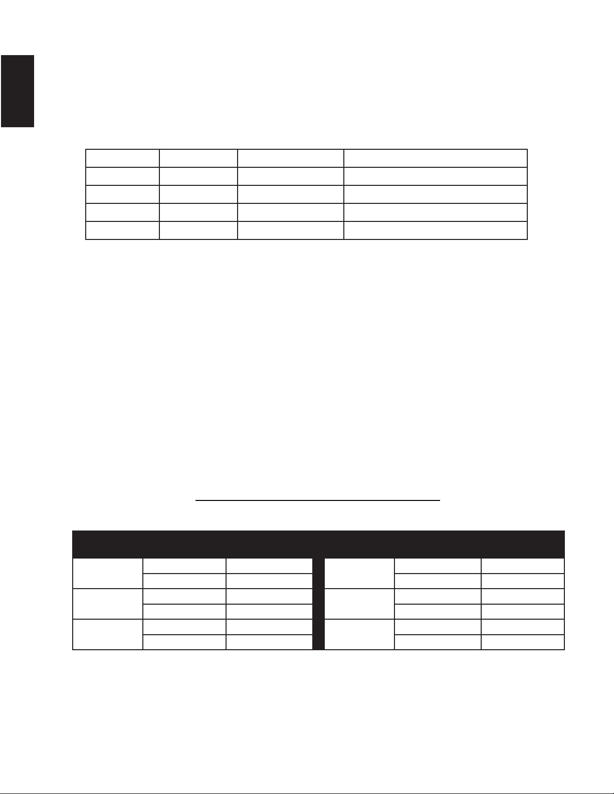
8.1A
** When a vertical rise is used as part of the venting confi guration, a 0" (0mm) rise per foot is acceptable.
For optimum performance, it is recommended that all horizontal runs have a 1" (25mm) rise per foot.
GX36 REQUIRED RISE ON HORIZONTAL
VENTING
B36 REQUIRED RISE ON HORIZONTAL
VENTING
Rear Vent Rigid Venting 1" (25mm) / FT** Rear Vent Rigid Venting 0" / FT
Flexible Venting 1" (25mm) / FT** Flexible Venting 0" / FT
Top Vent Rigid Venting 0" / FT Top Vent Rigid Venting 0" / FT
Flexible Venting 0" / FT Flexible Venting 0" / FT
Corner Vent Rigid Venting 6" (152mm) Corner Vent Rigid Venting 0"
Flexible Venting 6" (152mm) Flexible Venting 6" (152mm)
11
W415-1401 / C / 03.18.15
EN
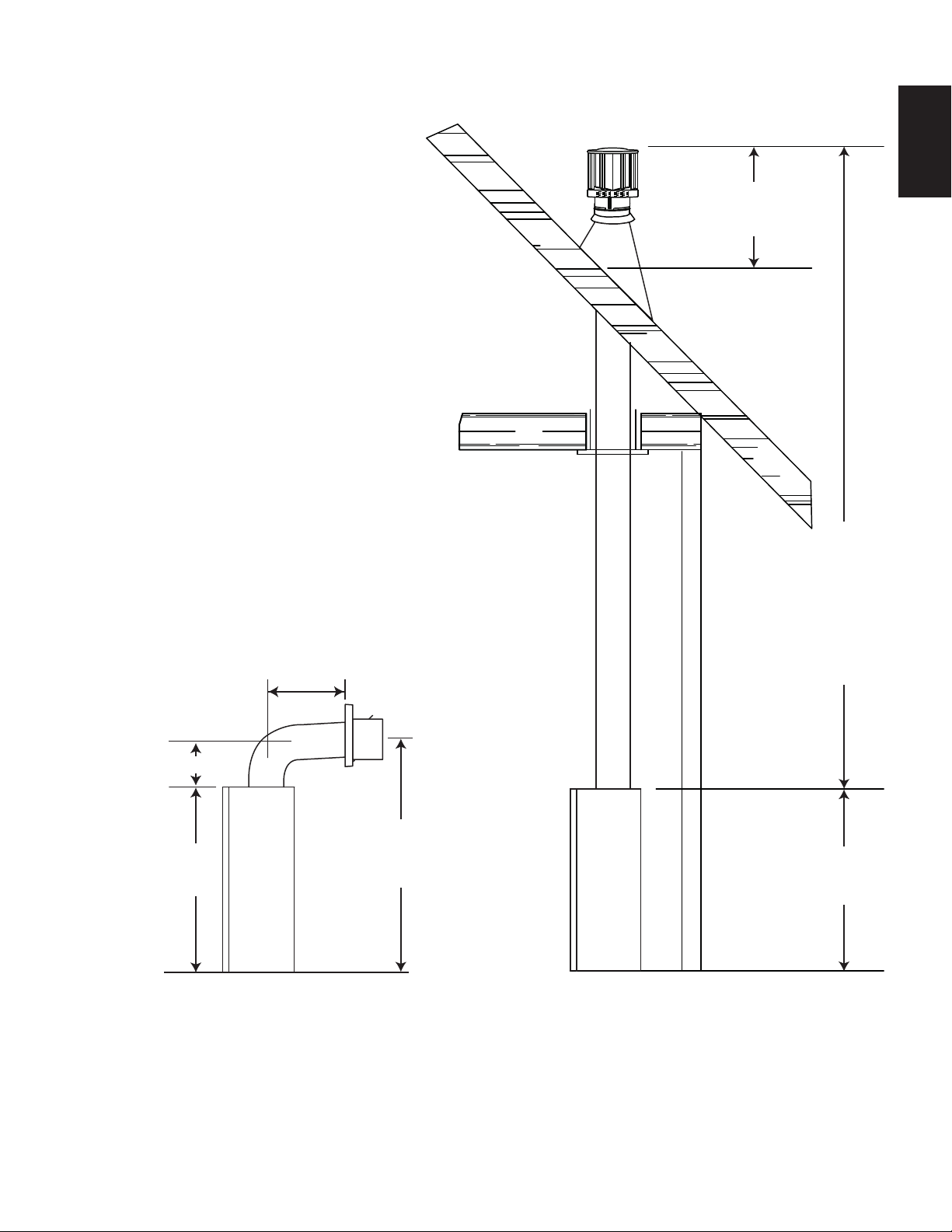
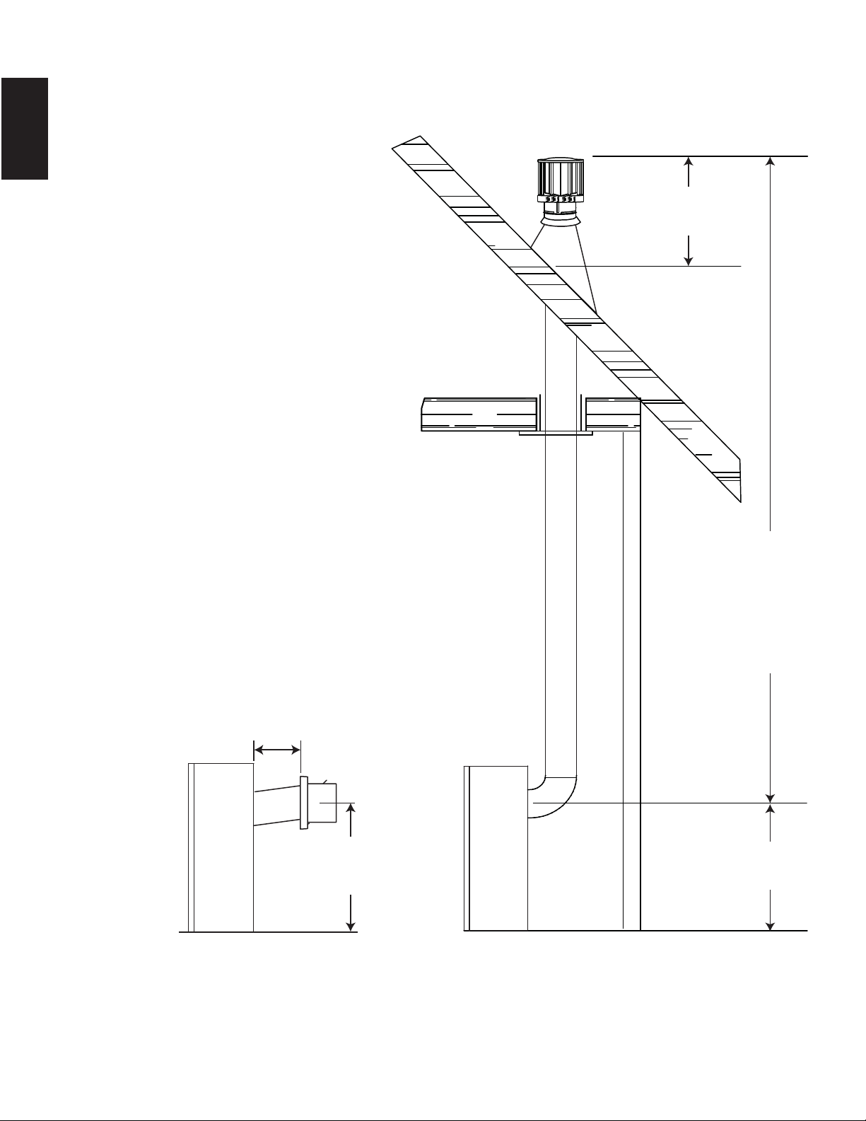
3.2 TYPICAL VENT INSTALLATION
16" (406MM)
MINIMUM
40 FT (12M)
MAXIMUM
3 FT (1M)
MINIMUM
34 1/16"
(865MM)
TOP VENT
8" (203MM)
MINIMUM
34 1/16"
(865MM)
42 1/16" (1068MM)
MINIMUM PLUS
RISE*
24" (610MM)
MAXIMUM
12
W415-1401 / C / 03.18.15
EN
REAR VENT
40 FT (12M)
MAXIMUM
3 FT (1M)
MINIMUM
24"
(610MM)
16" (406MM)
MINIMUM
20"
(508MM)
MAX
24"
(610MM)
PLUS RISE
13
W415-1401 / C / 03.18.15
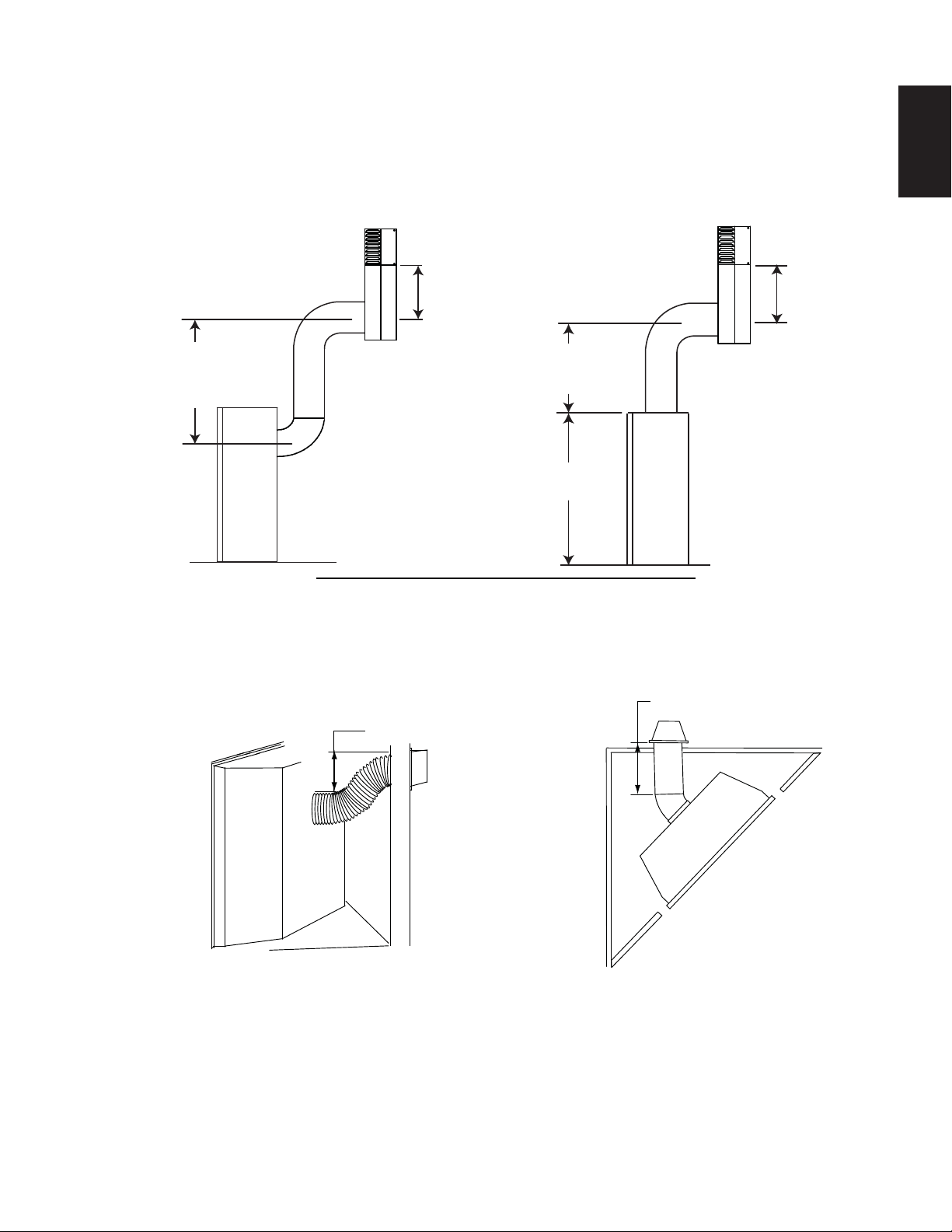
EN
3.3 SPECIAL VENT INSTALLATIONS
3.3.1 PERISCOPE TERMINATION
12" (305MM)
MINIMUM
TO GRADE
U
se the periscope kit to locate the air termination above grade. The periscope must be installed so that
w
hen fi nal grading is completed, the bottom air slot is located a minimum 12” (304.8mm) above grade. The
m
aximum allowable vent length is 10’ (3.1m) for a fi replace and 8’ (2.4m) for a stove.
9.4A
12" (305MM)
MINIMUM
TO GRADE
30" (762MM)
MINIMUM
30" (762MM)
MINIMUM
34 1/16"
(865MM)
20” (508mm)
MAXIMUM
6” (152.4mm)
RISE
3.3.2 CORNER TERMINATION
The maximum vent length for a corner installation is 20" (508mm) of horizontal run, in addition to the 45°
offset. In this case zero rise is acceptable. However, it is recommended a 6" (152mm) rise be included. See
illustrations below:
14
W415-1401 / C / 03.18.15
EN
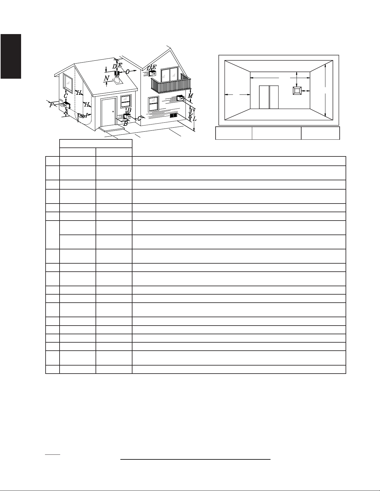
3.4 MINIMUM AIR TERMINAL LOCATION CLEARANCES
INSTALLATIONS
CANADA U.S.A.
A 12” (305mm) 12” (305mm) Clearance above grade, veranda porch, deck or balcony.
B 12” (305mm)
Δ
9”
(229mm)
Δ
Clearance to windows or doors that open.
C 12” (305mm)* 12” (305mm) * Clearance to permanently closed windows.
D
18”
(457mm)**
18” (457mm)**
Vertical clearance to ventilated soffi ts located above the terminal within a horizontal distance of 2’
(0.6m) from the center line of the terminal.
E 12” (305mm)** 12” (305mm)** Clearance to unventilated soffi t.
F 0” (0mm) 0” (0mm) Clearance to an outside corner wall.
G
0” (0mm)***
0”
(0mm)***
Clearance to an inside non-combustible corner wall or protruding non-combustible obstructions (chimney,
etc.).
2” (51mm)***
2”
(51mm)***
Clearance to an inside combustible corner wall or protruding combustible obstructions (vent chase,
etc.).
H 3’(0.9m) 3’ (0.9m)****
Clearance to each side of the center line extended above the meter / regulator assembly to a
maximum vertical distance of 15’ (4.6m).
I 3’ (0.9m) 3’ (0.9m)**** Clearance to a service regulator vent outlet.
J 12” (305mm) 9” (229mm)
Clearance to a non-mechanical air supply inlet to the building or a combustion air inlet to any other
appliance.
K 6’ (1.8m) 3’ (0.9m) † Clearance to a mechanical air supply inlet.
L 7’ (2.1m) ‡ 7’ (2.1m) **** Clearance above a paved sidewalk or paved driveway located on public property.
M
12”
(305mm)††
12”
(305mm)****
Clearance under a veranda, porch or deck.
N 16” (406mm) 16” (406mm) Clearance above the roof.
O 2’ (0.6m)†* 2’ (0.6m) †* Clearance from an adjacent wall including neighbouring buildings.
P 8’ (2.4m) 8’(2.4m) Roof must be non-combustible without openings.
Q 3’ (0.9m) 3’ (0.9m) See chart for wider wall dimensions.
R 6’ (1.8m) 6’ (1.8m)
See chart for deeper wall dimensions. The terminal shall not be installed on any wall that has an
opening between the terminal and the open side of the structure.
S 12” (305mm) 12” (305mm) Clearance under a covered balcony
Δ
The terminal shall not be located less than 6 feet under a window that opens on a horizontal plane in a structure with three walls and a roof.
* Recommended to prevent condensation on windows and thermal breakage
** It is recommended to use a heat shield and to maximize the distance to vinyl clad soffi ts.
*** The periscope requires a minimum 18 inches clearance from an inside corner.
**** This is a recommended distance. For additional requirements check local codes.
† 3 feet above if within 10 feet horizontally.
‡ A vent shall not terminate where it may cause hazardous frost or ice accumulations on adjacent property surfaces.
†† Permitted only if the veranda, porch, or deck is fully open on a minimum of two sides beneath the fl oor.
†* Recommended to prevent recirculation of exhaust products. For additional requirements check local codes.
††* Permitted only if the balcony is fully open on a minimum of one side.
12.1D
NOTE: Clearances are in accordance with local installation codes and the requirements of the gas supplier.
COVERED BALCONY APPLICATIONS ††*
Q
MIN
R
MAX
MAX
R
= 3 feet
(0.9m)
= 2 x
IHHW
(4.6m)
Q
ACTUAL
R
Q
S
G
P
15
W415-1401 / C / 03.18.15
EN
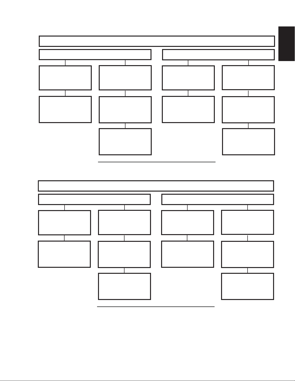
3.5 VENTING APPLICATION FLOW CHART
13.3A
TOP EXIT
Horizontal Termination
Vertical Termination
Vertical rise is equal
to or greater than
the horizontal run
Vertical rise is less
than horizontal run
Vertical rise is equal
to or greater than
the horizontal run
Vertical rise is less
than horizontal run
Horizontal run +
vertical rise to
maximum of
35 feet (10.7m)
Horizontal run +
vertical rise to
maximum of 24.75
feet (7.5m)
Horizontal run +
vertical rise to
maximum of
35 feet (10.7m)
Horizontal run +
vertical rise to
maximum of
35 feet (10.7m)
4.2 times the
vertical rise equal to
or greater than the
horizontal run
3 times the vertical
rise equal to or
greater than the
horizontal run
13.2A
REAR EXIT
Horizontal Termination
Vertical Termination
Vertical rise is equal
to or greater than
the horizontal run
Vertical rise is less
than horizontal run
Vertical rise is equal
to or greater than
the horizontal run
Vertical rise is less
than horizontal run
Horizontal run +
vertical rise to
Horizontal run +
vertical rise to
maximum of
24.75 feet (7.5m)
Horizontal run +
vertical rise to
Horizontal run +
vertical rise to
3.5 times the
vertical rise equal to
or greater than the
horizontal run
3 times the vertical
rise equal to or
greater than the
horizontal run
maximum of 40 feet
(12m)
maximum of 40 feet
(12m)
maximum of 40 feet
(12m)

16
W415-1401 / C / 03.18.15
EN
3.6 DEFINITIONS
14.1
For the following symbols used in the venting calculations and examples are:
> - greater than
> - equal to or greater than
< - less than
< - equal to or less than
H
T
- total of both horizontal vent lengths (Hr) and offsets (Ho) in feet
H
R
- combined horizontal vent lengths in feet
H
O
- offset factor: .03 (total degrees of offset - 90°*) in feet
V
T
- combined vertical vent lengths in feet
3.7 ELBOW VENT LENGTH VALUES
15.1A
FEET INCHES MILLIMETERS
1° 0.03 0.5 12.7
15° 0.45 6.0 152.4
30° 0.9 11.0 279.4
45° 1.35 16.0 406.4
90°* 2.7 32.0 812.8
* The fi rst 90° offset has a zero value and is shown in the formula as - 90°
17
W415-1401 / C / 03.18.15
EN
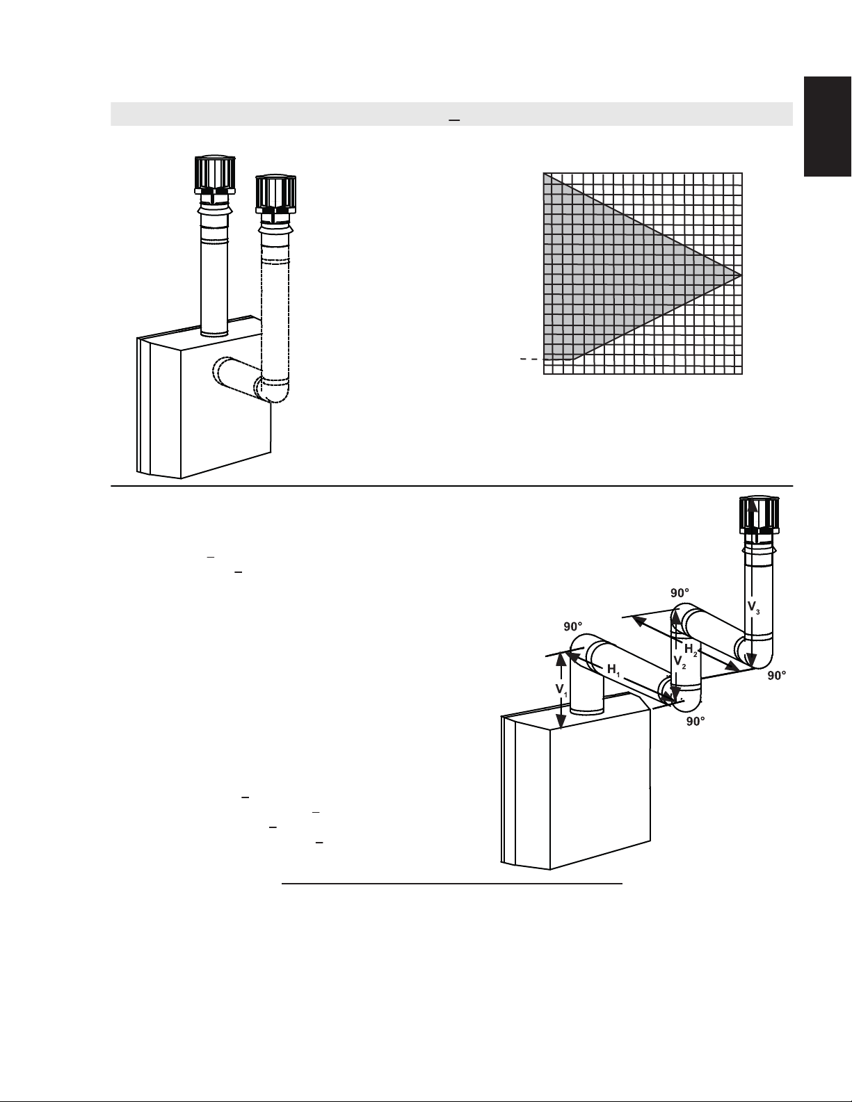
16.1B
Simple venting confi guration (only one 90° elbow)
(H
T
) < (V
T
)
For vent confi gurations requiring more than one 90° elbow, the following formulas apply:
Formula 1: H
T
< V
T
Formula 2: H
T
+ V
T
< 40 feet (12.2m)
Example:
V
1
= 3 FT (0.9m)
V
2
= 8 FT (2.4m)
V
T
= V
1
+ V
2
= 3 FT (0.9m ) + 8 FT (2.4m) = 11 FT (3.4m)
H
1
= 2.5 FT (0.8m)
H
2
= 2 FT (0.6m)
H
R
= H
1
+ H
2
= 2.5 FT (0.8m) + 2 FT (0.6m) = 4.5 FT (1.4m)
H
O
= .03 (three 90° elbows - 90°) = .03 (270° - 90°) = 5.4 FT (1.7m)
H
T
= H
R
+ H
O
= 4.5 FT (1.4m) + 5.4 FT (1.6m) = 9.9 FT (3m)
H
T
+ V
T
= 9.9 FT (3m) + 11 FT (3.4m) = 20.9 FT (6.4m)
Formula 1: H
T
< V
T
9.9 FT (3m) < 11 FT (3.4m)
Formula 2: H
T
+ V
T
< 40 FT (12.2m)
20.9 FT (6.4m) < 40 FT (12.2m)
Since both formulas are met, this vent confi guration is acceptable.
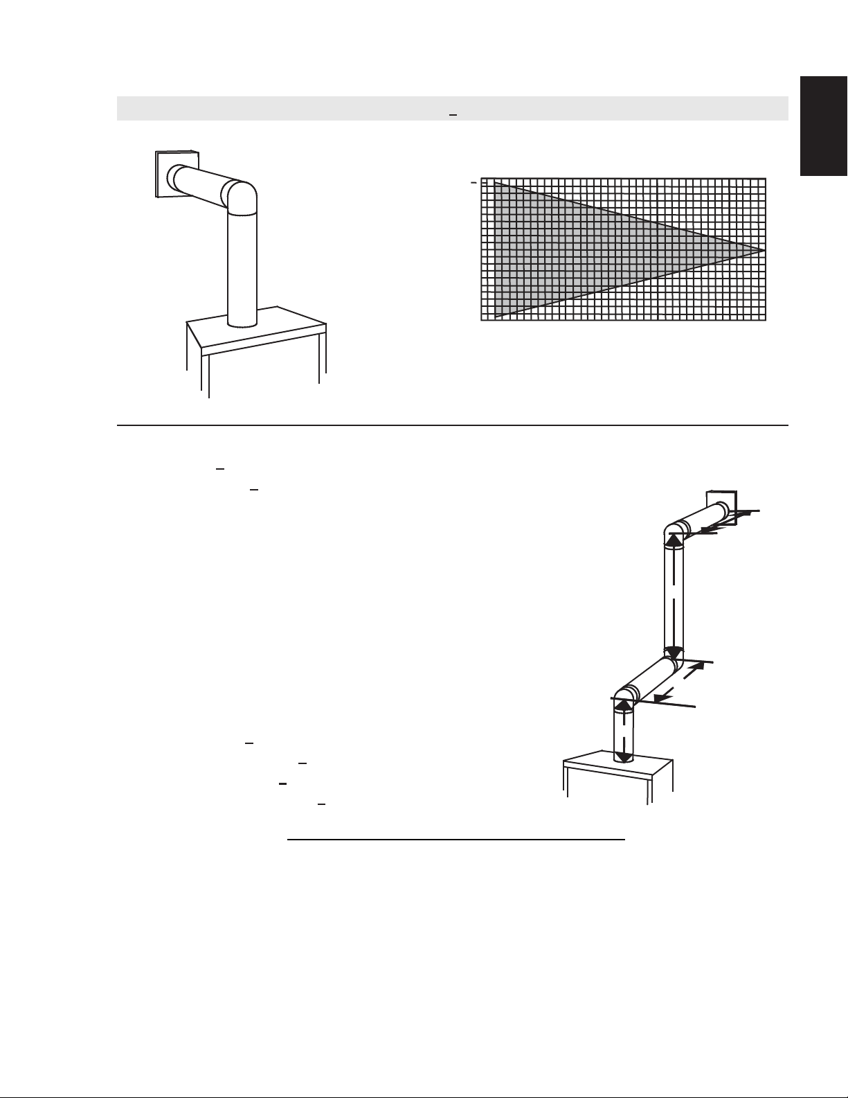
See graph to determine the required vertical
rise V
T
for the required horizontal run H
T
.
The shaded area within the lines represents
acceptable values for H
T
and V
T
0
2.5
(0.8)
5
(1.5)
7.5
(2.3)
10
(3.1)
12.5
(3.8)
15
(4.6)
40 (12.2)
10 (3.1)
20 (6.1)
30 (9.1)
17.5
(5.3)
20
(6.1)
39 (11.9)
REQUIRED
VERTICAL
RISE IN FEET
(METERS)V
T
HORIZONTAL VENT RUN PLUS OFFSET IN
FEET (METERS) H
T
90°
90°
90°
V
1
V
2
H
1
H
2
3.8 TOP EXIT HORIZONTAL TERMINATION
18
W415-1401 / C / 03.18.15
EN
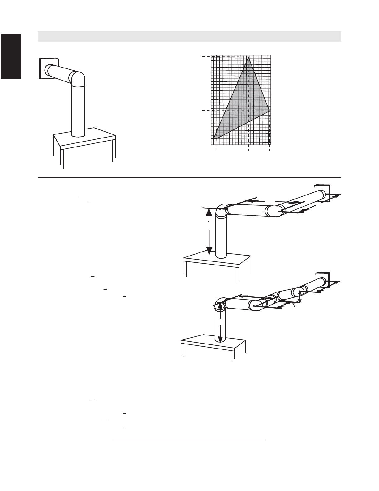
(H
T
) > (V
T
)
Simple venting configuration
(only one 90° elbow)
See graph to determine the required vertical rise V
T
for the required horizontal run H
T
.
HORIZONTAL VENT RUN PLUS OFFSET IN FEET (METERS) H
T
For vent configurations requiring more than one 90° elbow, the following formulas apply:
Formula 1: H
T
< 4.2 V
T
Formula 2: H
T
+ V
T
< 24.75 feet (7.5m)
Example:
V
1
= V
T
= 6 FT (1.8m)
H
1
= 3 FT (0.9m)
H
2
= 5 FT (1.5m)
H
R
= H
1
+ H
2
= 3FT (0.9m) + 5FT (1.5m) = 8FT (2.4m)
H
O
= .03 (two 90° elbows - 90°) = .03 (180° - 90°) = 2.7FT (0.8m)
H
T
= H
R
+ H
O
= 8FT (2.4m) + 2.7FT (0.8m) = 10.7FT (3.3m)
H
T
+ V
T
= 10.7FT (3.3m) + 6FT (1.8m) = 16.7FT (5.1m)
Formula 1: H
T
< 4.2 V
T
4.2 V
T
= 4.2FT (1.3m) x 6FT (1.8m) = 25.2FT (7.7m)
Formula 2: H
T
+ V
T
< 24.75 FT (7.5m)
16.7 FT (5.1m) < 24.75 FT (7.5m)
Since both formulas are met, this vent configuration is acceptable.
The shaded area within the lines represents acceptable values for H
T
and V
T
90°
V
1
H
1
H
2
90°
Example:
V
1
= 4 FT (1.2m)
V
2
= 1.5 FT (0.5m)
V
T
= V
1
+ V
2
= 4 FT (1.2m) + 1.5 FT (0.5m) = 5.5 FT (1.7m)
H
1
= 2 FT (0.6m)
H
2
= 1 FT (0.3m)
H
3
= 1 FT (0.3m)
H
4
= 1.5 FT (0.5m)
H
R
= H
1
+ H
2
+ H
3
+ H
4
= 2FT (0.6m) + 1FT (0.3m) + 1FT (0.3m) + 1.5FT (0.5m) = 5.5 FT (1.7m)
H
O
= .03 (four 90° elbows - 90°) = .03 (360° - 90°) = 8.1 FT (2.5m)
H
T
= H
R
+ H
O
= 5.5 FT (1.7m) + 8.1 FT (2.5m) = 13.6 FT (4.2m)
H
T
+ V
T
= 13.6 FT (4.2m) + 5.5 FT (1.7m) = 19.1 FT (5.8m)
Formula 1: H
T
< 4.2 V
T
4.2 V
T
= 4.2 FT (1.3m) x 5.5 FT (1.7m) = 23.1 FT (7m)
13.6 FT (4.2m) < 23.1 FT (7m)
Formula 2: H
T
+ V
T
< 24.75 FT (7.5m)
19.1 FT (5.8m) < 24.75 FT (7.5m)
Since both formulas are met, this vent configuration is acceptable.
90°
90°
90°
90°
H
1
H
2
V
1
V
2
H
3
H
4
0
5
(1.5)
15
(4.6)
20 (6.1)
100 (2540)
50 (1270)
150 (3810)
12.5
(3.8)
10 (254)
57 (1447.8)
147 (3733.8)
2
(0.6)
10
(3.1)
19.5
(5.9)
REQUIRED
VERTICAL
RISE IN INCHES
(MILLIMETERS) V
T
16.2_3B
19
W415-1401 / C / 03.18.15
EN
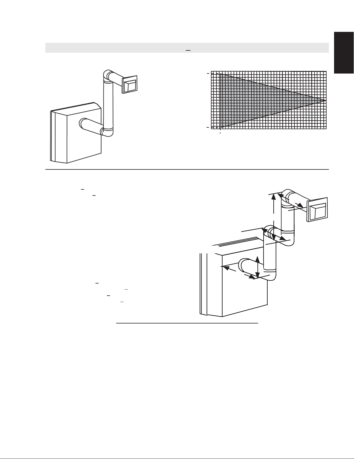
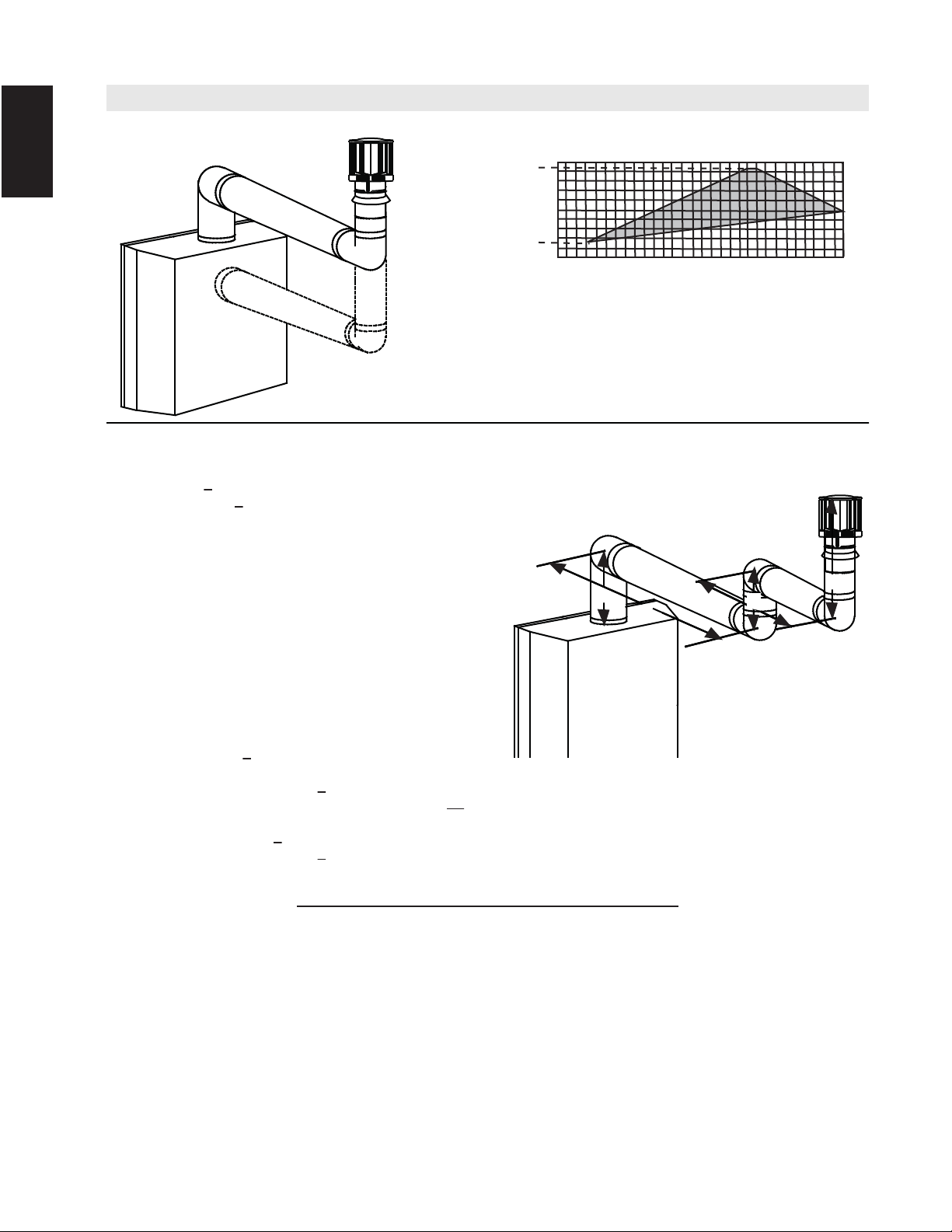
3.9 REAR EXIT HORIZONTAL TERMINATION
0
2.5
(0.8)
5
(1.5)
7.5
(2.3)
10
(3.1)
12.5
(3.8)
15
(4.6)
40 (12.2)
10 (3.1)
20 (6.1)
30 (9.1)
17.5
(5.3)
20
(6.1)
1.6
(0.5)
1.6 (0.5)
38.3 (11.7)
90°
V
1
V
2
H
1
H
2
90°
90°
90°
H
3
Simple venting configuration
(only two 90° elbows)
See graph to determine the required vertical rise V
T
for the required
horizontal run H
T
.
REQUIRED
VERTICAL
RISE IN
FEET
(METERS) V
T
HORIZONTAL VENT RUN PLUS OFFSET IN FEET (METERS) H
T
The shaded area within the lines represents acceptable values for H
T
and H
T
(H
T
) < (V
T
)
16.3A
For vent configurations requiring more than two 90° elbows, the following formulas apply:
Formula 1: H
T
< V
T
Formula 2: H
T
+ V
T
< 40 feet (12.2m)
Example:
V
1
= 9 FT (2.7m)
V
2
= 6 FT (1.8m)
V
T
= V
1
+ V
2
= 9FT (2.7m) + 6FT (1.8m) = 15FT (4.6m)
H
1
= 3 FT (0.9m)
H
2
= 2 FT (0.6m)
H
3
= 1.5 FT (0.5m)
H
R
= H
1
+ H
2
+ H
3
= 3FT (0.9m) + 2FT (0.6m) + 1.5FT (0.5m) = 6.5FT (2m)
H
O
= .03 (four 90° elbows - 90°) = .03 (360° - 90°) = 8.1 FT (2.5m)
H
T
= H
R
+ H
O
= 6.5FT (2m) + 8.1FT (2.5m) = 14.6FT (4.5m)
H
T
+ V
T
= 14.6FT (4.5m) + 15FT (4.6m) = 29.6 FT (9m)
Formula 1: H
T
< V
T
14.6 FT (4.5m) < 15 FT (4.6m)
Formula 2: H
T
+ V
T
< 40 FT (12.2m)
29.6 FT (9m) < 40 FT (12.2m)
Since both formulas are met, this vent configuration is acceptable.
20
W415-1401 / C / 03.18.15
EN
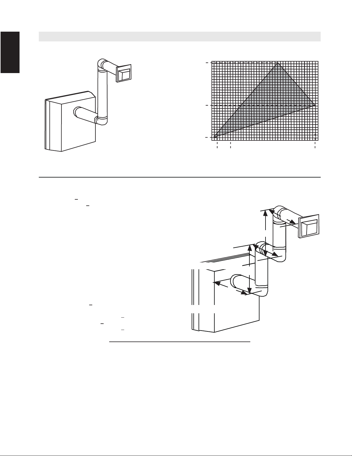
Simple venting configuration
(only two 90° elbows)
See graph to determine the required vertical rise V
T
for the
required horizontal run H
T
.
REQUIRED
VERTICAL RISE IN
INCHES
(MILLIMETERS)V
T
HORIZONTAL VENT RUN PLUS OFFSET IN FEET (METERS) H
T
The shaded area within the lines represents acceptable
values for H
T
and H
T
90°
V
1
V
2
H
1
H
2
90°
90°
90°
H
3
(H
T
) > (V
T
)
50 (1270)
100 (2540)
150(3810)
0
2.5
(0.8)
5
(1.5)
7.5
(2.3)
10
(3.1)
12.5
(3.8)
15
(4.6)
17.5
(5.3)
20
(6.1)
147 (3733.8
12
(304.8)
66
(1676.4)
1
(0.3)
3.5
(1.1)
19.25
(5.9)
16.3_2B
For vent configurations requiring more than two 90° elbows, the following formulas apply:
Formula 1: H
T
< 3.5V
T
Formula 2: H
T
+ V
T
< 24.75 feet (7.5m)
Example:
V
1
= 4 FT (1.2m)
V
2
= 1.5 FT (0.5m)
V
T
= V
1
+ V
2
= 4FT (1.2m) + 1.5FT (0.5m) = 5.5 FT (1.7m)
H
1
= 2 FT (0.6m)
H
2
= 1 FT (0.3m)
H
3
= 1 FT (0.3m)
H
4
= 1.5 FT (0.5m)
H
R
= H
1
+ H
2
+H
3
+H
4
= 2FT(0.6m) + 1FT(0.3m) + 1FT(0.3m) + 1.5FT(0.5m) = 5.5 FT(1.7m)
H
O
= .03 (four 90° elbows + one 45° elbow - 90°)
= .03 (90 + 90 + 90 + 90 + 45 - 90) = 9.45 FT (2.9m)
H
T
= H
R
+ H
O
= 5.5FT (1.7m) + 9.45FT (2.9m) = 14.95FT (4.6m)
H
T
+ V
T
= 14.95FT (4.6m) + 5.5FT (1.7m) = 20.45FT (6.2m)
Formula 1: H
T
< 3.5V
T
3.5V
T
= 3.5FT (1.1m) x 5.5FT (1.7m) = 19.25FT (5.9m)
14.95 FT (4.6m) < 19.25 FT (5.9m)
Formula 2: H
T
+ V
T
< 24.75 FT (7.5m)
20.45 FT (6.2m) < 24.75 FT (7.5m)
Since both formulas are met, this vent configuration is acceptable.
50 (1270)
100 (2540)
150(3810)
0
2.5
(0.8)
5
(1.5)
7.5
(2.3)
10
(3.1)
12.5
(3.8)
15
(4.6)
17.5
(5.3)
20
(6.1)
147 (3733.8
8 (203)
66
(1676.4)
1
(0.3)
3.5
(1.1)
19.25
(5.9)
21
W415-1401 / C / 03.18.15
EN
3.10 TOP OR REAR EXIT VERTICAL TERMINATION
Simple venting configurations.
See graph to determine the required vertical rise V
T
for the
required horizontal run H
T
.
REQUIRED
VERTICAL RISE
IN FEET
(METERS)V
T
HORIZONTAL VENT RUN PLUS OFFSET IN FEET
(METERS) H
T
The shaded area within the lines represents acceptable
values for H
T
and H
T
0
5
(1.5)
10
(3.1)
15
(4.6)
20
(6.1)
40 (12.2)
10 (3.1)
20 (6.1)
30 (9.1)
3 (0.9)
(H
T
) < (V
T
)
18.2A
For vent configurations requiring one or more 90° elbows (top exit) or one or more 90° elbows
(rear exit), the following formulas apply:
Formula 1: H
T
< V
T
Formula 2: H
T
+ V
T
< 40 feet (12.2m)
Example:
V
1
= 5 FT (1.5m)
V
2
= 6 FT (1.8m)
V
3
= 10 FT (3.1m)
V
T
= V
1
+ V
2
+ V
3
= 5FT (1.5m) + 6FT (1.8m) + 10FT (3.1m) = 21 FT (6.4m)
H
1
= 8 FT (2.4m)
H
2
= 2.5 FT (0.8m)
H
R
= H
1
+ H
2
= 8FT (2.4m) + 2.5FT (0.8m) = 10.5FT (3.2m)
H
O
= .03 (four 90° elbows - 90°)
= .03 (360° - 90°) = 8.1 FT (2.5m)
H
T
= H
R
+ H
O
= 10.5FT (3.2m) + 8.1FT (2.5m) = 18.6FT (5.7m)
H
T
+ V
T
= 18.6FT (5.7m) + 21FT (6.4m) = 39.6FT (12.1m)
Formula 1: H
T
< 3.5V
T
18.6 FT (5.7m) < 21 FT (6.4m)
Formula 2: H
T
+ V
T
< 40 FT (12.2m)
39.6FT (12.1m) < 40 FT (12.2m)
Since both formulas are met, this vent configuration is acceptable.
22
W415-1401 / C / 03.18.15
EN
Simple venting configurations.
See graph to determine the required vertical rise V
T
for the
required horizontal run H
T
.
REQUIRED
VERTICAL
RISE IN
FEET
(METERS)V
T
HORIZONTAL VENT RUN PLUS OFFSET IN FEET (METERS)H
T
The shaded area within the lines represents acceptable
values for H
T
and H
T
0
5
(1.5)
10
(3.1)
15
(4.6)
20
(6.1)
10 (3.1)
20 (6.1)
3 (0.9)
25
(7.6)
30
(9.1)
19 (5.8)
90°
V
1
H
1
H
2
90°
90°
90°
V
3
V
2
(H
T
) > (V
T
)
18.2_2B
For vent configurations requiring more than two 90° elbows (top exit) or one 90° elbow (rear exit), the following
formulas apply:
Formula 1: H
T
< 3 V
T
Formula 2: H
T
+ V
T
< 40 feet (12.2m)
Example:
V
1
= 2 FT (0.6m)
V
2
= 1 FT (0.3m)
V
3
= 1.5 FT (0.5m)
V
T
= V
1
+ V
2
+ V
3
= 2FT (0.6m) + 1FT (0.3m) + 1.5FT (0.5m) = 4.5 FT (1.4m)
H
1
= 6 FT (1.8m)
H
2
= 2 FT (0.6m)
H
R
= H
1
+ H
2
= 6FT (1.8m) + 2FT (0.6m) = 8 FT (2.4m)
H
O
= .03 (four 90° elbows - 90°)
= .03 (360° - 90°) = 8.1 FT (2.5m)
H
T
= H
R
+ H
O
= 8FT (2.4m) + 8.1FT (2.5m) = 16.1FT (4.9m)
H
T
+ V
T
= 16.1FT (4.9m) + 4.5FT (1.4m) = 20.6FT (6.3m)
Formula 1: H
T
< 3.5 V
T
3.5 V
T
= 3FT (0.9m) x 4.5FT (1.4m) = 13.5 FT (4.1m)
16.1FT (4.9m) < 13.5 FT (4.1m)
Since this formula is not met, this vent configuration is unacceptable.
Formula 2: H
T
+ V
T
< 40 FT (12.2m)
16.1FT (4.9m) < 13.5 (4.1m)
Since only formula 2 is met, this vent configuration is unacceptable and a new fireplace location or vent configuration will
need to be established to satisfy both formulas.
23
W415-1401 / C / 03.18.15
EN
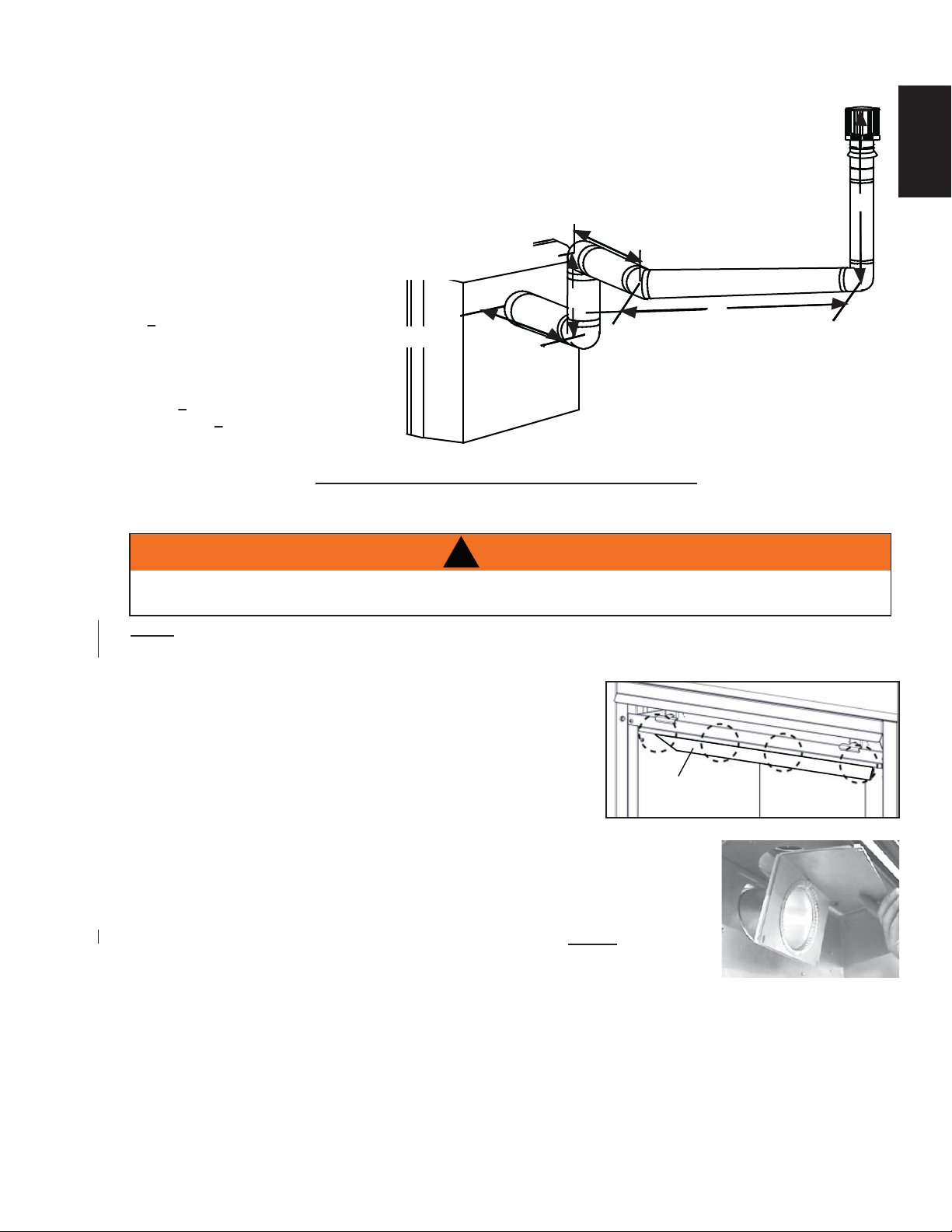
3.11 REAR EXIT
!
WARNING
FAILURE TO INSTALL THE CAP WILL CAUSE THE APPLIANCE TO FUNCTION IMPROPERLY AND
CAN CAUSE INJURY OR PROPERTY DAMAGE.
A. Remove the safety screen and glass front, refer to "
SAFETY SCREEN & DOOR REMOVAL / INSTALLATION"
section.
B. Remove the contents from the fi rebox and set aside, you
will need the exhaust fl ue collar from the top of the log
carton.
C. To ease assembly, remove the four hex head screws
securing the defl ector from inside the top front of the fi rebox, refer to Figure 1.
D. Place the gasket (provided) over the 4" (102mm) fl ue collar assembly and
bend along perforation.
E. From inside the fi rebox, insert the 4" (102mm) fl ue collar through the back
of the fi rebox. Secure the fl ue collar assembly and gasket using the four
hex head 3/8" thread cutting screws, refer to Figure 2. NOTE: Do not
overtighten. The gasket needs only to be snug against the fi rebox.
F. Re-attach the defl ector using the four screws and install the log set, glass
door and safety screen.
Fig. 2
DEFLECTOR
90°
V
1
V
2
H
1
H
2
90°
90°
H
3
45°
18.2_3A
Example:
V
1
= 1.5 FT (0.5m)
V
2
= 5 FT (1.5m)
V
T
= V
1
+ V
2
= 1.5FT (0.5m)+ 5FT (1.5m) = 6.5 FT (2m)
H
1
= 1 FT (0.3m)
H
2
= 1 FT (0.3m)
H
3
= 10.75 FT (3.3m)
H
R
= H
1
+ H
2
+ H
3
= 1FT (0.3m) + 1FT (0.3m) + 10.75FT (3.3m) = 12.75FT (3.9m)
H
O
= .03 (four 90° elbows + one 45° elbow - 90°)
= .03 (360° + 45° - 90°) = 6.75 FT (2.1m)
H
T
= H
R
+ H
O
= 12.75FT (3.9m) + 6.75FT (2.1m) = 19.5 FT (5.9m)
H
T
+ V
T
= 19.5FT (5.9m) + 6.5FT (2m) = 26 FT (7.9m)
Formula 1:
H
T
< 3 V
T
3 V
T
= 3FT (0.9m) x 6.5FT (2m) = 19.5FT (5.9m)
19.5FT (5.9m) = 19.5FT (5.9m)
Formula 2:
H
T
+ V
T
< 40 FT (12.2m)
26 FT (7.9m) < 40 FT (12.2m)
Since both formulas are met, this vent configuration is acceptable.
Fig. 1
NOTE: A #42 orifi ce was supplied with your appliance. In installations with a vertical rise greater than
8" (203mm) in the vent confi guration, the #42 orifi ce must be used to increase the fl ame size.
24
W415-1401 / C / 03.18.15
EN
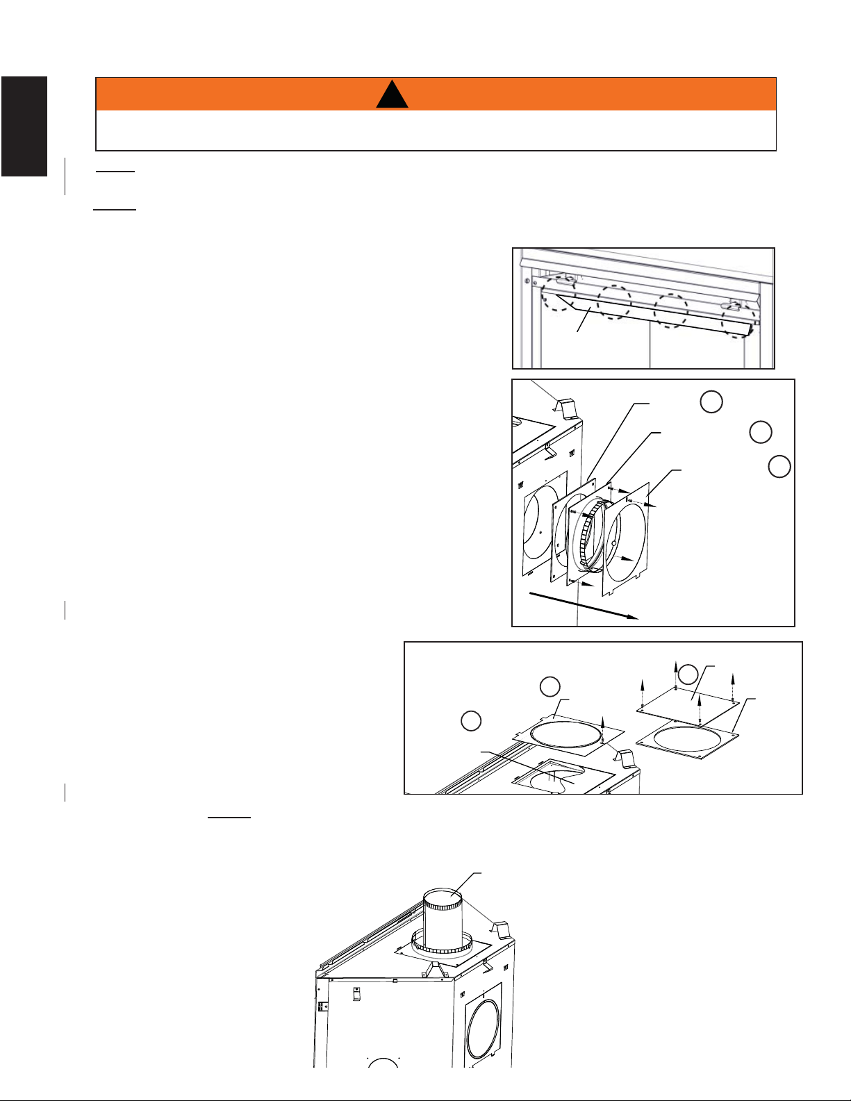
3.12 TOP EXIT
A. Remove the safety screen and glass front, refer to " SAFETY SCREEN & DOOR REMOVAL /
INSTALLATION" section.
B. Remove the contents from the fi rebox and set aside, you
will need the fl ue collar from the top of the log carton.
C. To ease assembly, remove the four hex head screws
securing the defl ector from inside the top front of the
fi rebox.
D. Remove the single screw from the outer cover on the
back of the appliance.
E. Remove the four screws on the 7" (178mm) intake collar
assembly; set the intakecollar and gasket aside. Careful
not to damage gasket.
F. Remove the single screw from the outer cover with
knockout intact, on the top of the appliance and set
aside.
G. Remove the inner cover plate and gasket by removing
the four screws. Reinstall the inner cover plate and
gasket onto the back of the appliance.
H. Take the outer cover (with knockout intact) and secure
onto the back of the appliance.
I. Remove and discard the 1 1/2" thick batt of insulation.
J. Place the 7" (178mm) intake collar and gasket into the
top of the appliance and secure with
the four screws.
K. Re-install the outer cover (without
knock out) over the 7" (178mm)
exhaust collar assembly and secure.
L. From inside the fi rebox, install the 4"
(102mm) exhaust collar up through the
top of the fi rebox and secure with the
the four hex head 3/8" thread cutting
screws. NOTE: Do not overtighten.
The gasket needs only to be snug against the fi rebox.
M. Re-attach the top defl ector, log set, glass door and safety screen.
NOTE: This appliance has been factory shipped as a rear vent.
EXHAUST FLUE COLLAR
INTAKE COLLAR
ASSEMBLY
GASKET
OUTER COVER
D
E
E
INNER
COVERPLATE
OUTER SHELL
KNOCKOUT
GASKET
F
F
G
OUTER
COVER
(with knockout)
!
WARNING
FAILURE TO INSTALL THE CAP WILL CAUSE THE APPLIANCE TO FUNCTION IMPROPERLY AND
CAN CAUSE INJURY OR PROPERTY DAMAGE.
DEFLECTOR
NOTE: A #42 orifi ce was supplied with your appliance. In installations with a vertical rise greater than
8" (203mm) in the vent confi guration, the #42 orifi ce must be used to increase the fl ame size.
25
W415-1401 / C / 03.18.15
EN
4.0 INSTALLATION
4.1 WALL AND CEILING PROTECTION
For clearances to combustible materials from the vent pipe, see “FRAMING” section.
!
WARNING
DO NOT FILL THE SPACE BETWEEN THE VENT PIPE AND ENCLOSURE WITH ANY TYPE OF
MATERIAL. DO NOT PACK INSULATION OR COMBUSTIBLES BETWEEN CEILING FIRESTOPS.
ALWAYS MAINTAIN SPECIFIED CLEARANCES AROUND VENTING AND FIRESTOP SYSTEMS.
INSTALL WALL SHIELDS AND FIRESTOPS AS SPECIFIED. FAILURE TO KEEP INSULATION OR
OTHER MATERIALS AWAY FROM VENT PIPE MAY CAUSE FIRE.
70.1
!
WARNING
ENSURE TO UNPACK ALL LOOSE MATERIALS FROM INSIDE THE FIREBOX PRIOR TO HOOKING UP
THE GAS AND ELECTRICAL SUPPLY.
IF YOUR APPLIANCE IS SUPPLIED WITH A REMOTE ENSURE THE REMOTE RECEIVER IS IN THE
“OFF” POSITION PRIOR TO HOOKING UP THE GAS AND ELECTRICAL SUPPLY TO THE APPLIANCE.
FOR SAFE AND PROPER OPERATION OF THE APPLIANCE, FOLLOW THE VENTING INSTRUCTIONS
EXACTLY.
ALL INNER EXHAUST AND OUTER INTAKE VENT PIPE JOINTS MAY BE SEALED USING EITHER RED
RTV HIGH TEMP SILICONE SEALANT W573-0002 (NOT SUPPLIED) OR BLACK HIGH TEMP MILL PAC
W573-0007 (NOT SUPPLIED) WITH THE EXCEPTION OF THE APPLIANCE EXHAUST FLUE COLLAR
WHICH MUST BE SEALED USING MILL PAC.
IF USING PIPE CLAMPS TO CONNECT VENT COMPONENTS, 3 SCREWS MUST ALSO BE USED TO
ENSURE THE CONNECTION CANNOT SLIP OFF.
DO NOT CLAMP THE FLEXIBLE VENT PIPE.
RISK OF FIRE, EXPLOSION OR ASPHYXIATION. IMPROPER SUPPORT OF THE ENTIRE VENTING
SYSTEM MAY ALLOW VENT TO SAG AND SEPARATE. USE VENT RUN SUPPORTS AND CONNECT
VENT SECTIONS PER INSTALLATION INSTRUCTIONS.
RISK OF FIRE, DO NOT ALLOW LOOSE MATERIALS OR INSULATION TO TOUCH THE VENT PIPE.
REMOVE INSULATION TO ALLOW FOR THE INSTALLATION OF THE ATTIC SHIELD AND TO
MAINTAIN CLEARANCES TO COMBUSTIBLES.
68.2B
26
W415-1401 / C / 03.18.15
EN
4.1.1 HORIZONTAL INSTALLATION
4.1.2 VERTICAL INSTALLATION
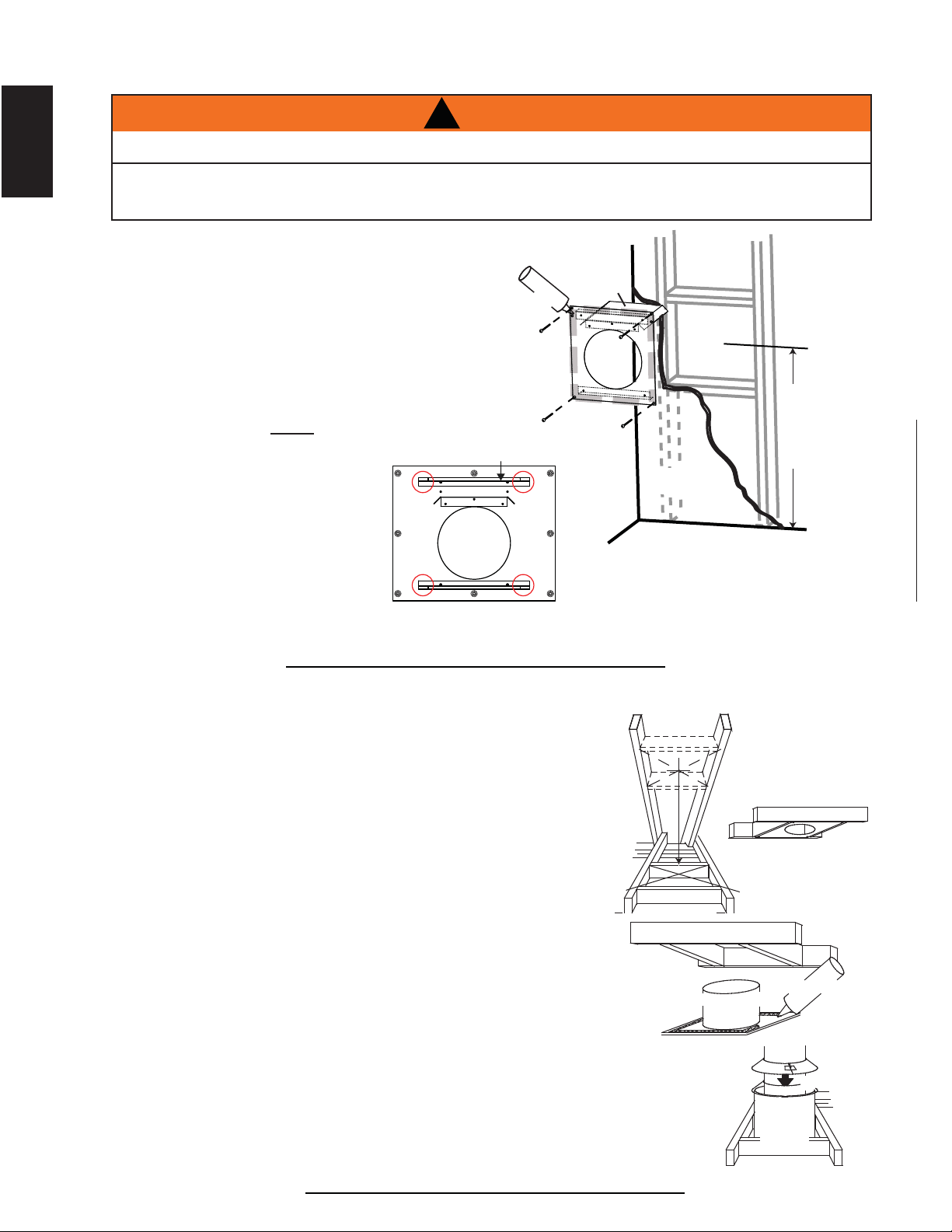
This application occurs when venting through a roof. Installation kits for
various roof pitches are available from your authorized dealer / distributor. See
accessories to order specifi c kits required.
A. Determine the air terminal location, cut and frame a square opening as
illustrated in the ceiling and the roof to provide the minimum 1" (25mm)
clearance between the vent pipe and any combustible material. Try to center
the vent pipe location midway between two joists to prevent having to cut
them. Use a plumb bob to line up the center of the openings. A vent pipe
shield will prevent any materials such as insulation, from fi lling up the 1"
(25mm) air space around the pipe. Nail headers between the joist for
extra support.
B. Apply a bead of caulking (not supplied) to the framework or to the Wolf
Steel vent pipe shield plate or equivalent (in the case of a fi nished ceiling),
and secure over the opening in the ceiling. A fi restop must be placed on the
bottom of each framed opening in a roof or ceiling that the venting system passes
through. Apply a bead of caulking all around and place a fi restop spacer over
the vent shield to restrict cold air from being drawn into the room or around the
fi replace. Ensure that both spacer and shield maintain the required clearance to
combustibles. Once the vent pipe is installed in its fi nal position, apply sealant between the
pipe and the fi restop assembly.
C. In the attic, slide the vent pipe collar down to cover up the open end of the shield and
tighten. This will prevent any materials, such as insulation, from fi lling up the 1" (25mm) air
space around the pipe.
21.1
CAULKING
VENT PIPE
SHIELD
FIRESTOP
UNDERSIDE OF
JOIST
VENT
PIPE
COLLAR
VENT
PIPE
SHIELD
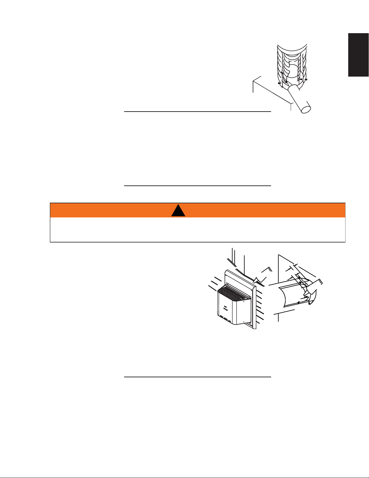
This application occurs when venting through an exterior wall.
Having determined the correct height for the air terminal
location, cut and frame a hole in the exterior wall as
illustrated to accommodate the fi restop assembly. Dry
fi t the fi restop assembly before proceeding to ensure
the brackets on the rear surface fi t to the inside
surface of the horizontal framing.
The vent shield must be installed to the full depth of
the combustible wall. The length of the vent shield
may be cut shorter for combustible walls that are less
than 6" (152mm) thick.
NOTE: Bend the tabs for reduced side
clearances or move the shield for reduced top clearances.
A. Apply a bead of caulking (not
supplied) around the corner
edge of the inside surface of the
fi restop assembly, fi t the fi restop
assembly to the hole and secure
using the 4 screws (supplied in
your manual baggie).
B. Once the vent pipe is installed in its fi nal position, apply high temperature sealant W573-0007 (not
supplied) between the pipe and the fi restop.
DETERMINE
THE
CORRECT
HEIGHT
CAULKING
FIRESTOP
SPACER
VENT
SHIELD
FINISHING
MATERIAL
20.7A
!
WARNING
THE FIRESTOP ASSEMBLY MUST BE INSTALLED WITH THE VENT SHIELD TO THE TOP.
TERMINALS MUST NOT BE RECESSED INTO A WALL OR SIDING MORE THAN THE DEPTH OF THE
RETURN FLANGE OF THE MOUNTING PLATE.
27
W415-1401 / C / 03.18.15
EN
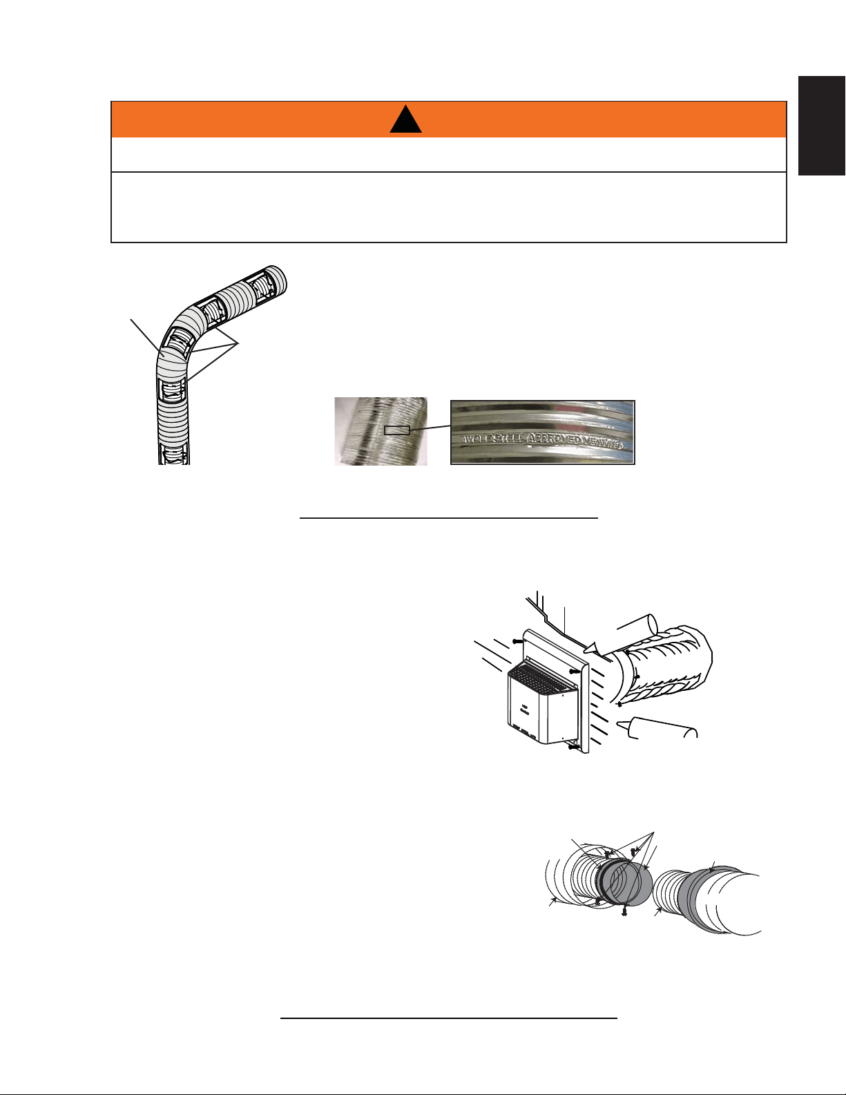
4.2 USING FLEXIBLE VENT COMPONENTS
For safe and proper operation of the appliance, follow the venting
instructions exactly.
All inner fl ex pipe and outer fl ex pipe joints may be sealed using high
temperature sealant W573-0002 (not supplied) or the high temperature
sealant W573-0007 Mill Pac (not supplied). However, the high temperature
sealant W573-0007 Mill Pac (not supplied) must be used on the joint
connecting the inner fl ex pipe and the exhaust fl ue collar.
Use only approved fl exible vent pipe kits marked:
“Wolf Steel Approved Venting” as identifi ed
by the stamp only on the outer fl ex pipe.
22.1
ELBOW
SPACERS
DO NOT ALLOW THE INNER FLEX PIPE TO BUNCH UP ON HORIZONTAL OR VERTICAL RUNS AND ELBOWS.
KEEP IT PULLED TIGHT.
SPACERS ARE ATTACHED TO THE INNER FLEX PIPE AT PREDETERMINED INTERVALS TO MAINTAIN AN EVEN
AIR GAP TO THE OUTER FLEX PIPE. THIS GAP IS REQUIRED FOR SAFE OPERATION. A SPACER IS REQUIRED
AT THE START, MIDDLE AND END OF EACH ELBOW TO ENSURE THIS GAP IS MAINTAINED. THESE SPACERS
MUST NOT BE REMOVED.
!
WARNING
4.2.1 HORIZONTAL AIR TERMINAL INSTALLATION
A. Stretch the inner fl ex pipe to the required length taking into
account the additional length needed for the fi nished wall
surface. Apply a heavy bead of the high temperature
sealant W573-0007 Mill Pac (not supplied) to the inner
sleeve of the air terminal. Slip the vent pipe a minimum
of 2” (50.8mm) over the inner sleeve of the air terminal
and secure with 3 #8 screws.
B. Using the outer fl ex pipe, slide over the outer combustion
air sleeve of the air terminal and secure with 3 #8 screws.
Seal using high temperature sealant W573-0002 (not
supplied).
C. Insert the vent pipes through the fi restop maintaining the required
clearance to combustibles. Holding the air terminal (lettering in
an upright, readable position), secure to the exterior wall and
make weather tight by sealing with caulking (not supplied).
D. If more vent pipe needs to be used to reach the fi replace, couple
them together as illustrated. The vent system must be
supported approximately every 3 feet (0.9m) for both vertical
and horizontal runs. Use noncombustible strapping to
maintain the minimum clearance to combustibles.
The air terminal mounting plate may be recessed into the exterior wall or siding no greater than the depth
of its return fl ange.
23.1B
SCREWS
#10x2"
2" (50.8mm) OVERLAP
OUTER FLEX PIPE
INNER FLEX
PIPE
HIGH TEMPERATURE
SEALANT
CAULKING
HI-TEMP
SEALANT
#8 X 1/2” SELF DRILLING
SCREWS
INNER COUPLER
OUTER COUPLER
OUTER
FLEX PIPE
INNER
FLEX PIPE
OUTER
FLEX PIPE
28
W415-1401 / C / 03.18.15
EN
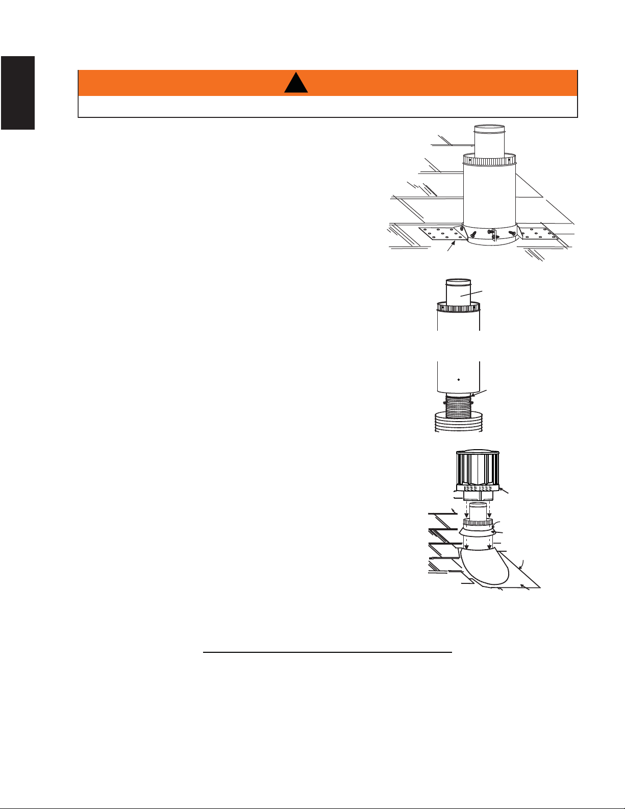
4.2.2 VERTICAL AIR TERMINAL INSTALLATION
A. Fasten the roof support to the roof using the screws provided. The
roof support is optional. In this case the venting is to be adequately
supported using either an alternate method suitable to the authority
having jurisdiction or the optional roof support.
B. Stretch the inner fl ex pipe to the required length. Slip the
inner fl ex pipe a minimum of 2” (51mm) over the inner pipe
of the air terminal connector and secure with 3 #8 screws.
Seal using a heavy bead of high temperature sealant
W573-0007 (not supplied).
C. Repeat using the outer fl ex pipe, using a heavy bead of
high temperature sealant W573-0002 (not supplied).
D. Thread the air terminal connector / vent pipe assembly down through
the roof. The air terminal must be positioned vertically and plumb.
Attach the air terminal connector to the roof support, ensuring that the
top of the air terminal is 16” (406mm) above the highest point that it
penetrates the roof.
E. Remove nails from the shingles, above and to the sides of the air
terminal connector. Place the fl ashing over the air terminal connector
leaving a min. 3/4” (19mm) of the air terminal connector showing
above the top of the fl ashing. Slide the fl ashing underneath the
sides and upper edge of the shingles. Ensure that the air terminal
connector is properly centred within the fl ashing, giving a 3/4”
(19mm) margin all around. Fasten to the roof. Do not nail through
the lower portion of the fl ashing. Make weather-tight by sealing with
caulking. Where possible, cover the sides and top edges of the
fl ashing with roofi ng material.
F. Aligning the seams of the terminal and air terminal connector,
place the terminal over the air terminal connector making sure
the vent pipe goes into the hole in the terminal. Secure with
the three screws provided.
G. Apply a heavy bead of weatherproof caulking 2” (51mm) above
the fl ashing. Install the storm collar around the air terminal and
slide down to the caulking. Tighten to ensure that a weather-
tight seal between the air terminal and the collar is achieved.
H. If more vent pipe needs to be used to reach the appliance see “HORIZONTAL
AIR TERMINAL INSTALLATION” section.
24.1A
STORM COLLAR
FLASHING
CAULKING
WEATHER
SEALANT
2” (51mm)
AIR INLET
BASE
ROOF SUPPORT
INNER FLEX PIPE
INNER PIPE
HIGH
TEMPERATURE
SEALANT
AIR
TERMINAL
CONNECTOR
OUTER FLEX PIPE
MAINTAIN A MINIMUM 2” (51mm) SPACE BETWEEN THE AIR INLET BASE AND THE STORM COLLAR.
!
WARNING
29
W415-1401 / C / 03.18.15
EN
4.2.3 APPLIANCE VENT CONNECTION
A. Install the inner exhaust fl ue collar to the appliance. Secure
with 3 screws. Seal the joint and screw holes using the high
temperature sealant Mill-Pac W573-0007 (not supplied).
B. Install the outer fl ex pipe to the appliance. Attach and seal the
joints using a high temperature sealant.
28.1C
2” (50.8mm)
OVERLAP
HIGH TEMP
SEALANT
#8 X 1/2”
SELF
DRILLING
SCREWS
4.3 USING RIGID VENT COMPONENTS
The vent system must be supported approximately every 3 feet (0.9m) for both vertical and horizontal runs.
Use Wolf Steel Ltd. support ring assembly or equivalent noncombustible strapping to maintain the minimum
clearance to combustibles for both vertical and horizontal runs.
A
ll inner exhaust and outer intake vent pipe joints may be sealed using either red high temperature silicone
sealant W573-0002 (not supplied) or black high temperature sealant W573-0007 Mill Pac (not supplied) with
the exception of the appliance exhaust fl ue collar which must be sealed using Mill Pac.
25.1A
4.3.1 HORIZONTAL AIR TERMINAL INSTALLATION
A. Move the appliance into position. Measure the
vent length required between terminal and
appliance taking into account the additional
length needed for the fi nished wall surface
and any 1¼” (31.8mm) overlaps between
venting components.
B. Apply high temperature sealant W573-0007 (not
supplied) to the outer edge of the inner exhaust fl ue
collar of the appliance. Attach the fi rst inner rigid
pipe component and secure using 3 self tapping
screws. Repeat using the outer rigid pipe.
C. Insert the vent pipes through the fi restop maintaining the required clearance to combustibles. Holding
the air terminal (lettering in an upright, readable position), secure to the exterior wall and make
weather tight by sealing with caulking (not supplied).
The air terminal mounting plate may be recessed into the exterior wall or siding no greater than the
depth of the return fl ange.
26.1A
SCREWS
#10x2"
OUTER
RIGID
PIPE
CAULKING
INNER
RIGID
PIPE
SCREWS
SELF DRILLING
#8x1/2"
1" (25.4mm)
OVERLAP
SEALANT
HI-TEMP
!
WARNING
RISK OF FIRE, DO NOT ALLOW LOOSE MATERIALS OR INSULATION TO TOUCH THE VENT PIPE.
REMOVE INSULATION TO ALLOW FOR THE INSTALLATION OF THE ATTIC SHIELD AND TO
MAINTAIN CLEARANCES TO COMBUSTIBLES.

30
W415-1401 / C / 03.18.15
EN
4.3.2 VERTICAL AIR TERMINAL INSTALLATION
A. Move the appliance into position.
B. Fasten the roof support to the roof using the screws provided. The
roof support is optional. In this case the venting is to be adequately
supported using either an alternate method suitable to the authority
having jurisdiction or the optional roof support.
C. Apply high temperature sealant (not supplied) to the outer edge of
the inner sleeve of the air terminal. Slip the inner coupler a minimum
of 2" (51mm)over the sleeve and secure using 3 screws.
D. Apply high temperature sealant (not supplied) to the outer edge of
the of the outside sleeve of the air terminal connector. Slip the outer
coupler over the sleeve and secure as before. Trim the outer coupler
even with the inner coupler end.
E. Thread the air terminal connector / vent pipe assembly down through
the roof support and attach, ensuring that a minimum 16" (406mm)
of air terminal connector will penetrate the roof when fastened. If
the attic space is tight, we recommend threading the Wolf Steel vent pipe collar or equivalent loosely
onto the air terminal connector / vent pipe assembly as it is passed through the attic. The air terminal
connector must be located vertically and plumb.
F. Remove nails from the shingles, above and to the sides of the air terminal
connector. Place the fl ashing over the air terminal connector and slide it
underneath the sides and upper edge of the shingles. Ensure that the air
terminal connector is properly centered within the fl ashing, giving a 3/4"
(19mm) margin all around. Fasten to the roof. Do NOT nail through the lower
portion of the fl ashing. Make weather-tight by sealing with caulking. Where
possible, cover the sides and top edges of the fl ashing with roofi ng material.
G. Apply a heavy bead of waterproof caulking 2" (51mm) above the fl ashing.
Install the storm collar around the air terminal and slide down to the caulking. Tighten to ensure that a
weather-tight seal between the air terminal connector and the collar is achieved.
H. Continue adding rigid venting sections, sealing and securing as above. Attach the inner collapsed
telescopic sleeve to the last section of rigid piping. Secure with screws and seal. Repeat using the
outer telescopic sleeve.
I. Run a bead of high temperature sealant (not supplied) around the outside of the inner exhaust fl ue
collar on the appliance. Pull the telescopic sleeve a minimum of 2" (51mm) onto the collar. Secure with
3 screws. Repeat with the outer telescopic sleeve.
J. In the attic, slide the vent pipe collar down to cover up the open end of the shield and tighten. This will
prevent any materials, such as insulation, from fi lling up the 1" (25mm) air space around the pipe.
27.2A
INNER RIGID
PIPE
OUTER
RIGID PIPE
INNER PIPE
HIGH
TEMPERATURE
SEALANT
AIR
TERMINAL
CONNECTOR
VENT
PIPE
COLLAR
VENT
PIPE
SHIELD
4.4 RESTRICTING VERTICAL VENTS
77.3
Vertical installations may display a very active
fl
ame. I
f
this appearance is not desirable, the vent exit must
be restricted using a restrictor vent kit. Refer to “ACCESORIES” in the “REPLACEMENTS” section for the
appropriate kit. This will reduce the velocity of the exhaust gases, slowing down the fl ame pattern and creating
a more traditional gentle fl ame appearance. Specifi c instructions are included with the kit.
31
W415-1401 / C / 03.18.15
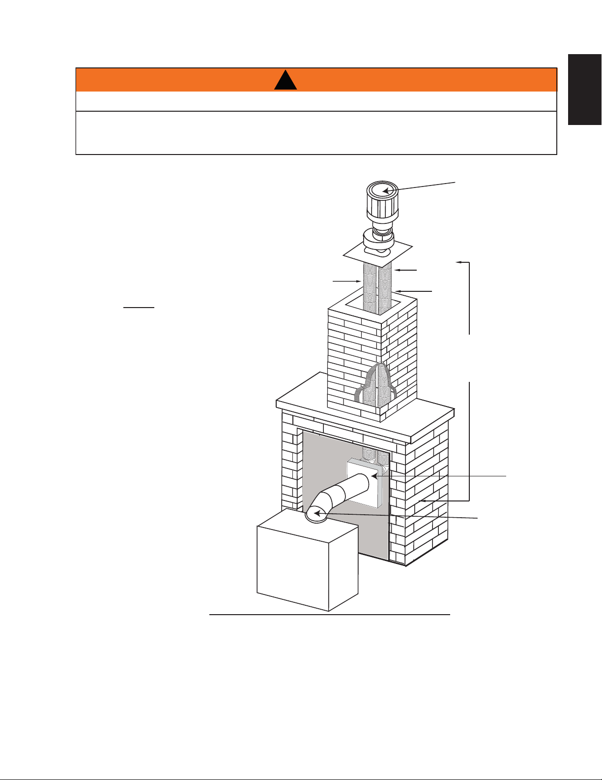
EN
7.6A
This appliance is designed to be attached to a 3” (76.2mm) co-linear aluminum fl ex vent system running the
full length of a masonry chimney.
The fl ex liners accommodate any contours of a
masonry chimney, however, it is necessary to keep
the fl exible liners as straight as possible. The inlet air
collar of the termination cap must be connected to
the air intake fl ex liner and the exhaust collar must be
connected to the exhaust fl exible liner.
Both Simpson Duravent and Selkirk co-linear to
co-axial adaptors have been approved on this
appliance (NOTE: A vent adaptor will be required
directly off the appliance).
Follow vent manufacturer’s installation instructions.
Different manufacturer’s venting components must
not be combined. Once the preferred manufacturer’s
appliance adaptor has been attached, the
remainder of the system must be that of the
same manufacturer.
The only exception to this rule is to use Wolf
Steel’s approved 3” (76.2mm) fl ex liner and
co-linear termination.
!
WARNING
RISK OF FIRE!
CO-AXIAL TO CO-LINEAR VENTING CONFIGURATIONS MUST ONLY BE USED IN A NON-
COMBUSTIBLE CHIMNEY OR ENCLOSURE. INSTALLATION IN A COMBUSTIBLE ENCLOSURE COULD
RESULT IN A FIRE.
AIR
INTAKE
EXHAUST
FLUE
FLEX
LINER
* 40 FT (12.2m)
MAX.
10 FT (3.1m)
MIN
COAXIAL TO
CO-LINEAR
ADAPATOR
APPLIANCE
VENT ADAPTOR
TERMINATION
* Measured from appliance fl ue collar to
termination fl ue collar
4.5 VERTICAL THROUGH EXISTING CHIMNEY

32
W415-1401 / C / 03.18.15
EN
This appliance is also certifi ed to be installed as an OEM (Original Equipment Manufacturer) installation
in a manufactured home (U.S. only) or mobile home and must be installed in accordance with the
manufacturer’s instructions and the Manufactured Home Construction and Safety Standard, Title 24 CFR,
Part 3280, in the United States or the Mobile Home Standard, CAN/CSA Z240 MH Series, in Canada. This
appliance is only for use with the type(s) of gas indicated on the rating plate.
29.1A
This Mobile/Manufactured Home Listed appliance comes factory equipped with a means to secure the unit. Built
in appliances are equipped with 1/4” (6.4mm) diameter holes located in the front left and right corners of the
base. Use #10 hex head screws, inserted through the holes in the base to secure. For free standing products
contact your local authorized dealer / distributor for the appropriate securing kit. For mobile home installations, the
appliance must be fastened in place. It is recommended that the appliance be secured in all installations. Always
turn off the pilot and the fuel supply at the source, prior to moving the mobile home. After moving the mobile home
and prior to lighting the appliance, ensure that the logs are positioned correctly.
This appliance is certifi ed to be installed in an aftermarket permanently located, manufactured (mobile)
home, where not prohibited by local codes.
This appliance is only for use with the type of gas indicated on the rating plate. This appliance is not
convertible for use with other gases, unless a certifi ed kit is used.
A
conversion kit is supplied with the mobile home appliance.
Conversion Kits
This appliance is fi eld convertible between Natural Gas (NG) and Propane (LP).
To convert from one gas to another consult your Authorized dealer/distributor.
4.6 MOBILE HOME INSTALLATION
33
W415-1401 / C / 03.18.15
EN
4.7 GAS INSTALLATION
30.1A
Installation and servicing to be done by a qualifi ed installer. Do not use open fl ame.
• Move the appliance into position and secure.
• If equipped with a fl ex connector the appliance is designed to accept a 1/2” (13mm) gas supply.
Without the connector it is designed to accept a 3/8” (9.5mm) gas supply. The appliance is equipped
with a manual shut off valve to turn off the gas supply to the appliance.
• Connect the gas supply in accordance to local codes. In the absence of local codes, install to the
current CAN/CSA-B149.1 Installation Code in Canada or to the current National Fuel Gas Code, ANSI
Z223.1 / NFPA 54 in the United States.
• When fl exing any gas line, support the gas valve so that the lines are not bent or kinked.
• Check for gas leaks by brushing on a soap and water solution.
!
WARNING
RISK OF FIRE, EXPLOSION OR ASPHYXIATION. ENSURE THERE ARE NO IGNITION SOURCES SUCH AS
SPARKS OR OPEN FLAMES.
SUPPORT GAS CONTROL WHEN ATTACHING GAS SUPPLY PIPE TO PREVENT DAMAGING GAS LINE.
ALWAYS LIGHT THE PILOT WHETHER FOR THE FIRST TIME OR IF THE GAS SUPPLY HAS RUN OUT
WITH THE GLASS DOOR OPENED OR REMOVED. PURGING OF THE GAS SUPPLY LINE SHOULD BE
PERFORMED BY A QUALIFIED SERVICE TECHNICIAN. ASSURE THAT A CONTINUOUS GAS FLOW IS AT
THE BURNER BEFORE CLOSING THE DOOR. ENSURE ADEQUATE VENTILATION. FOR GAS AND
ELECTRICAL LOCATIONS, SEE “DIMENSION” SECTION.
ALL GAS CONNECTIONS MUST BE CONTAINED WITHIN THE APPLIANCE WHEN COMPLETE.
HIGH PRESSURE WILL DAMAGE VALVE. DISCONNECT GAS SUPPLY PIPING BEFORE TESTING GAS
LINE AT TEST PRESSURES ABOVE 1/2 PSIG.
VALVE SETTINGS HAVE BEEN FACTORY SET, DO NOT CHANGE.
4.8 OPTIONAL WALL SWITCH
50.6
For ease of accessibility, an optional remote wall switch or millivolt thermostat may be installed in a convenient
location. Route a 2 strand, solid core millivolt wire from the valve to the wall switch or millivolt thermostat. The
recommended maximum lead length depends on wire size:
WIRE SIZE MAX. LENGTH
14 gauge (1.8mm) 100 feet (30.5m)
16 gauge (1.5mm) 60 feet (18.3m)
18 gauge (1.2mm) 40 feet (12.2m)
*
Refer to"WIRING DIAGRAM"
!
WARNING
DO NOT CONNECT EITHER THE WALL SWITCH, THERMOSTAT OR GAS VALVE DIRECTLY TO 110
VOLT ELECTRICITY.
34
W415-1401 / C / 03.18.15
EN
5.0 FRAMING
5.1 B36 FRAMING
!
WARNING
RISK OF FIRE!
IN ORDER TO AVOID THE POSSIBILITY OF EXPOSED INSULATION OR VAPOUR BARRIER COMING
IN CONTACT WITH THE APPLIANCE BODY, IT IS RECOMMENDED THAT THE WALLS OF THE
APPLIANCE ENCLOSURE BE “FINISHED” (IE: DRYWALL / SHEETROCK), AS YOU WOULD FINISH
ANY OTHER OUTSIDE WALL OF A HOME. THIS WILL ENSURE THAT CLEARANCE TO
COMBUSTIBLES IS MAINTAINED WITHIN THE CAVITY.
DO NOT NOTCH THE FRAMING AROUND THE APPLIANCE STAND-OFFS. FAILURE TO MAINTAIN
AIR SPACE CLEARANCE MAY CAUSE OVER HEATING AND FIRE. PREVENT CONTACT WITH
SAGGING OR LOOSE INSULATION OR FRAMING AND OTHER COMBUSTIBLE MATERIALS. BLOCK
OPENING INTO THE CHASE TO PREVENT ENTRY OF BLOWN-IN INSULATION. MAKE SURE
INSULATION AND OTHER MATERIALS ARE SECURED.
WHEN CONSTRUCTING THE ENCLOSURE ALLOW FOR FINISHING MATERIAL THICKNESS TO
MAINTAIN CLEARANCES. FRAMING OR FINISHING MATERIAL CLOSER THAN THE MINIMUMS
LISTED MUST BE CONSTRUCTED ENTIRELY OF NON-COMBUSTIBLE MATERIALS. MATERIALS
CONSISTING ENTIRELY OF STEEL, IRON, BRICK, TILE, CONCRETE, SLATE, GLASS OR PLASTERS,
OR ANY COMBINATION THEREOF ARE SUITABLE. MATERIALS THAT ARE REPORTED AS PASSING
ASTM E 136, STANDARD TEST METHOD FOR BEHAVIOUR OF MATERIALS IN A VERTICAL TUBE
FURNACE AT 1382° F (750°C) AND UL763 SHALL BE CONSIDERED NON-COMBUSTIBLE
MATERIALS.
MINIMUM CLEARANCE TO COMBUSTIBLES MUST BE MAINTAINED OR A SERIOUS FIRE HAZARD
COULD RESULT.
THE APPLIANCE REQUIRES A MINIMUM ENCLOSURE HEIGHT. MEASURE FROM THE APPLIANCE
BASE.
IF STEEL STUD FRAMING KITS WITH CEMENT BOARD ARE PROVIDED, OR SPECIFIED IN THE
INSTALLATION INSTRUCTIONS. THEY MUST BE INSTALLED.
FINISHING MUST BE DONE USING A NON-COMBUSTIBLE MATERIAL EXTENDING FROM THE TOP
OF THE APPLIANCE SUCH AS NON-COMBUSTIBLE BOARD, CERAMIC TILE, MARBLE, ETC. DO
NOT USE WOOD OR DRYWALL.
ANY FIRE RATED DRYWALL IS NOT ACCEPTABLE.
71.1B
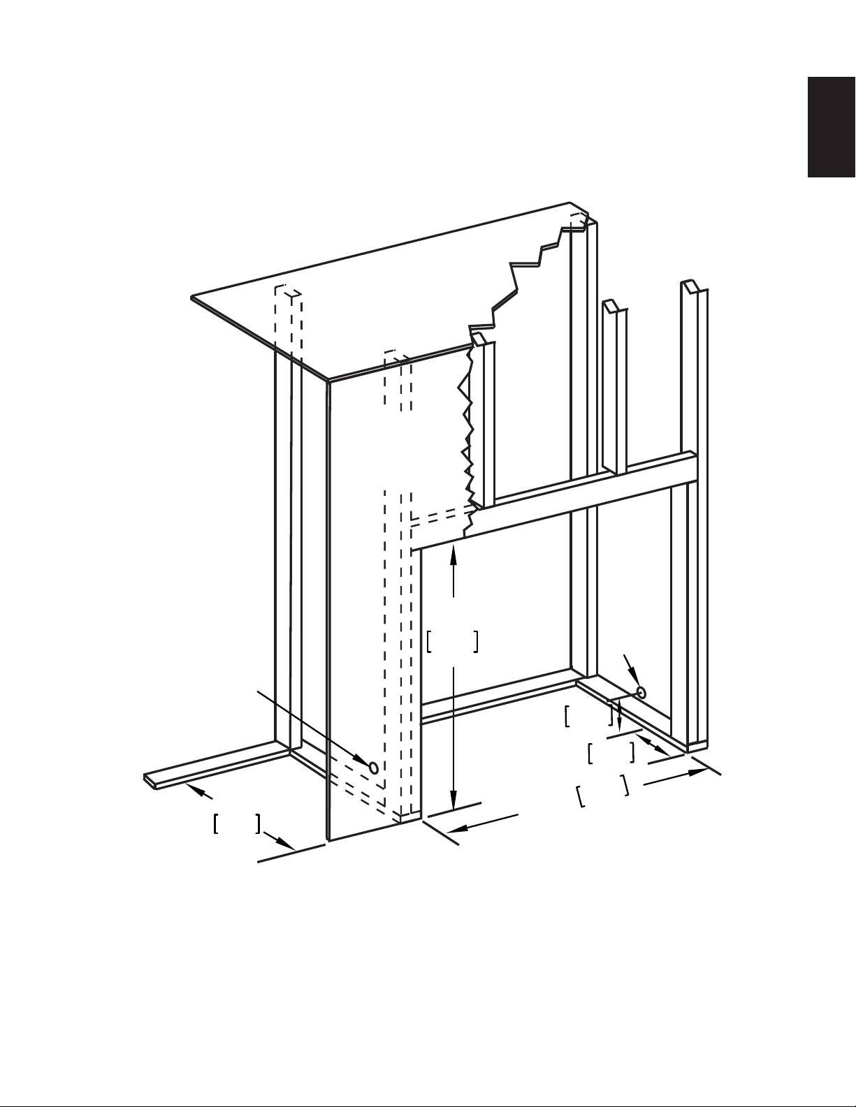
35
W415-1401 / C / 03.18.15
EN
5.1.1 MINIMUM FRAMING DIMENSIONS B36
35 1/2"
902mm
35"
889mm
1 7/8"
47mm
8"
203mm
16"
406mm
GAS
INLET
LOCATION
ELECTRICAL
CONNECTION
ENCLOSURE
TOP
FINISHING
MATERIAL
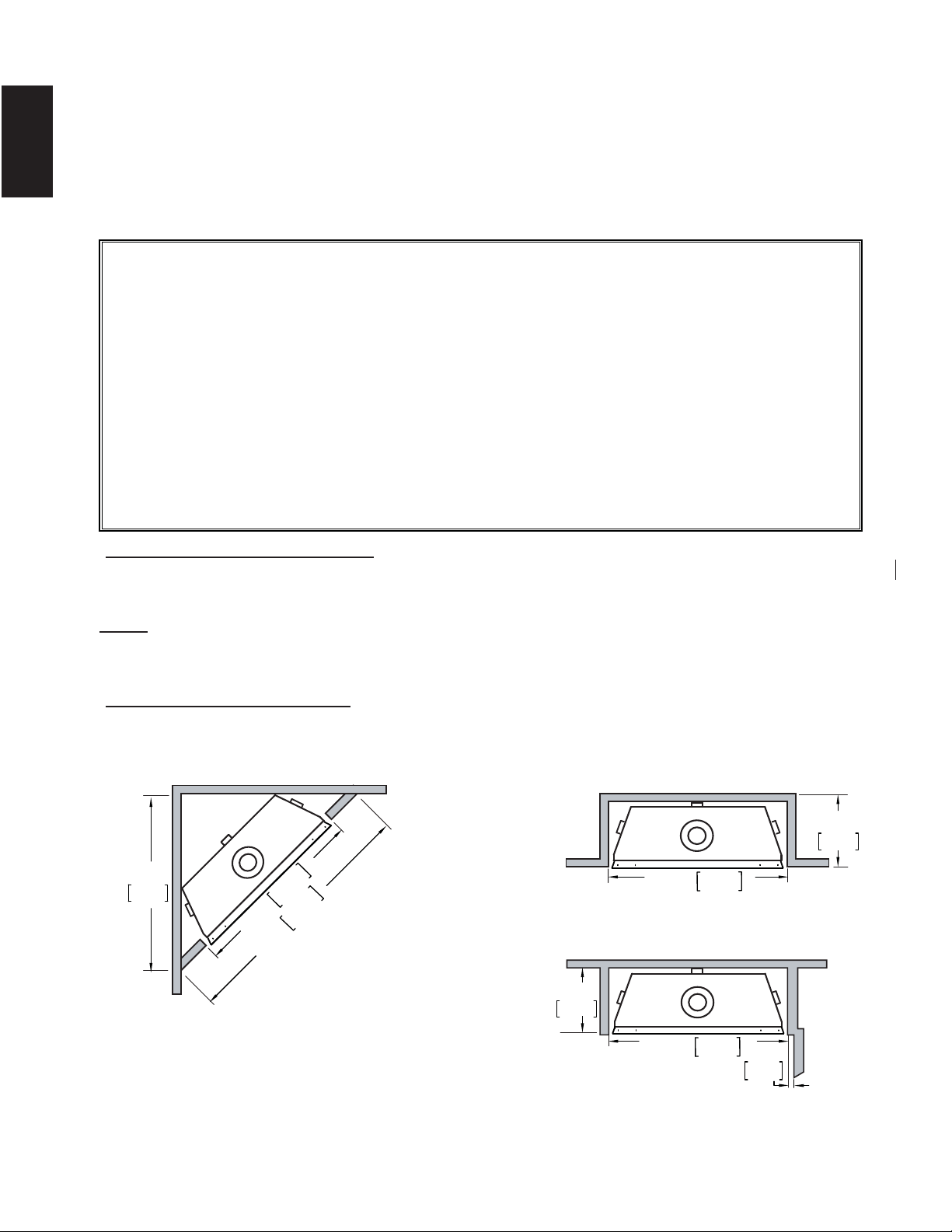
36
W415-1401 / C / 03.18.15
EN
35 1/2"
902mm
49 1/8"
1248mm
31 7/8"
810mm
It is best to frame your appliance after it is positioned and the vent system is installed. Frame to local building
codes.
It is not necessary to install a hearth extension with this appliance.
When roughing in the appliance, raise the appliance to accommodate for the thickness of the fi nished fl oor
materials, i.e. tile, carpeting, hard wood, which if not planned for will interfere with the opening of the lower
access door and the installation of many decorative fl ashing accessories.
Combustible materials may be installed fl ush with the front of the appliance but must not cover any of the black
face-areas of the appliance. Non-combustible material (brick, stone or ceramic tile) may protrude in these areas.
Minimum clearance to combustible construction from appliance and vent surfaces:
Combustible Framing:
- 0" to stand-offs
- 1" (25mm) to bottom and sides of the vent pipe*
- 3" (76mm) to top of the vent pipe*
Combustible Finishing:
- 0" to rear stand offs
- 0" to front face top and sides
Top Exit
- 50 1/2" (1283mm) to combustible enclosure top from base of the appliance
- 54" (1372mm) to ceiling from base of the appliance
Rear Exit
- 41" (1041mm) to combustile enclosure top from base of the appliance
- 54" (1372mm) to ceiling from base of the appliance
*B36 HORIZONTAL VENT SECTIONS: A minimum of 1" (25mm) at the bottom and sides and 3" (76mm) at
the top of the vent pipe on all horizontal runs to combustibles is required. Use fi restop spacer W010-3440
(supplied).
NOTE: The minimum clearances from the top of the horizontal vent pipe to combustible materials may
be reduced from 3" (76mm) to 1" (25mm) in those installations with a minimum 38" (965mm) vertical
vent rise made immediately off the fi replace collar.
*B36 VERTICAL VENT SECTIONS: A minimum of 1" (25mm) all around the vent pipe on all vertical runs
to combustibles is required except for clearances in appliance enclosures. See "MINIMUM ENCLOSURE
CLEARANCES" section. Use fi restop spacer W500-0096 (not supplied).
INSIDE
CHASE
OUTSIDE
CHASE
SIDE
WALL
16”
406mm
16"
406mm
2"
51mm
35 1/2"
902mm
35 1/2"
902mm
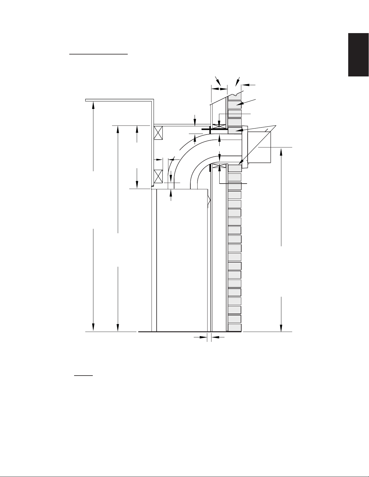
37
W415-1401 / C / 03.18.15
EN
5.2 MINIMUM ENCLOSURE CLEARANCES
3" [76mm]
COMBUSTIBLE
NON-COMBUSTIBLE
BRICK
0” (0MM) IF
NON-COMBUSTIBLE
FINISHING IS USED
SUCH AS BRICK
AND STONE.
3" [76mm]
MINIMUM
3" [76mm]
2"
[51mm]
1"
[25mm]
50 1/2"
[1283mm]
54"
[1372mm]
CEILING
(MIN)
42 1/16"
[1068mm]
MINIMUM
PLUS RISE*
16 1/4"
[412mm]
1"
[25mm]
TOP EXIT ENCLOSURE
The appliance requires a minimum enclosure height of 50 1/2" (1282mm). For temperature
requirements, the enclosure space around and above the appliance must be left
unobstructed.
B36 TOP VENT
NOTE: The vent shield is telescopic and must be adjusted to shield the full depth of the
combustible wall penetration.
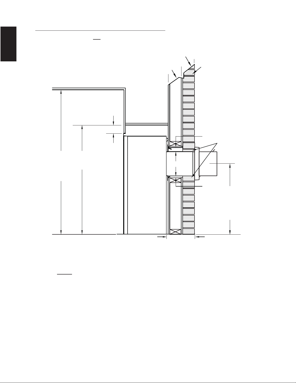
38
W415-1401 / C / 03.18.15
EN
* See "VENTING" section.
REAR EXIT ENCLOSURE
The appliance requires a minimum enclosure height of 41" (1041mm). For temperature
requirements, the enclosure space around and above the appliance must be left
unobstructed.
24"
[610mm]
MINIMUM
PLUS RISE*
COMBUSTIBLE
NON-COMBUSTIBLE
1"
[25mm]
3"
[76mm]
BRICK
0” (0MM) IF
NON-COMBUSTIBLE
FINISHING IS USED
SUCH AS BRICK
AND STONE.
7"
[178mm]
41"
[1041mm]
1"-10"
[25mm-254mm]
VENT RUN
54"
[1376mm]
CEILING
(MIN)
B36 MINIMUM REAR VENT CLEARANCES
For rear vent termination not exceeding 10" (254mm) of horizontal vent run.
NOTE: The vent shield is telescopic and must be adjusted to shield the full depth of the
combustible wall penetration.
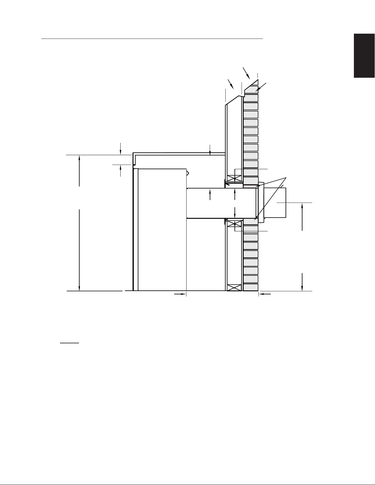
39
W415-1401 / C / 03.18.15
EN
REAR EXIT ENCLOSURE
The appliance requires a minimum enclosure height of 41" (1041mm). For temperature
requirements, the enclosure space around and above the appliance must be left
unobstructed.
B36 MAXIMUM REAR VENT CLEARANCES (EXAMPLE 1)
24"
[610mm]
MINIMUM
PLUS RISE*
COMBUSTIBLE
NON-COMBUSTIBLE
1"
[25mm]
3"
[76mm]
BRICK
0” (0MM) IF
NON-COMBUSTIBLE
FINISHING IS USED
SUCH AS BRICK
AND STONE.
7"
[178mm]
41"
[1041mm]
10"-20"
[254mm-508mm]
VENT RUN
11 1/2"
[368mm]
NOTE: The vent shield is telescopic and must be adjusted to shield the full depth of the
combustible wall penetration.
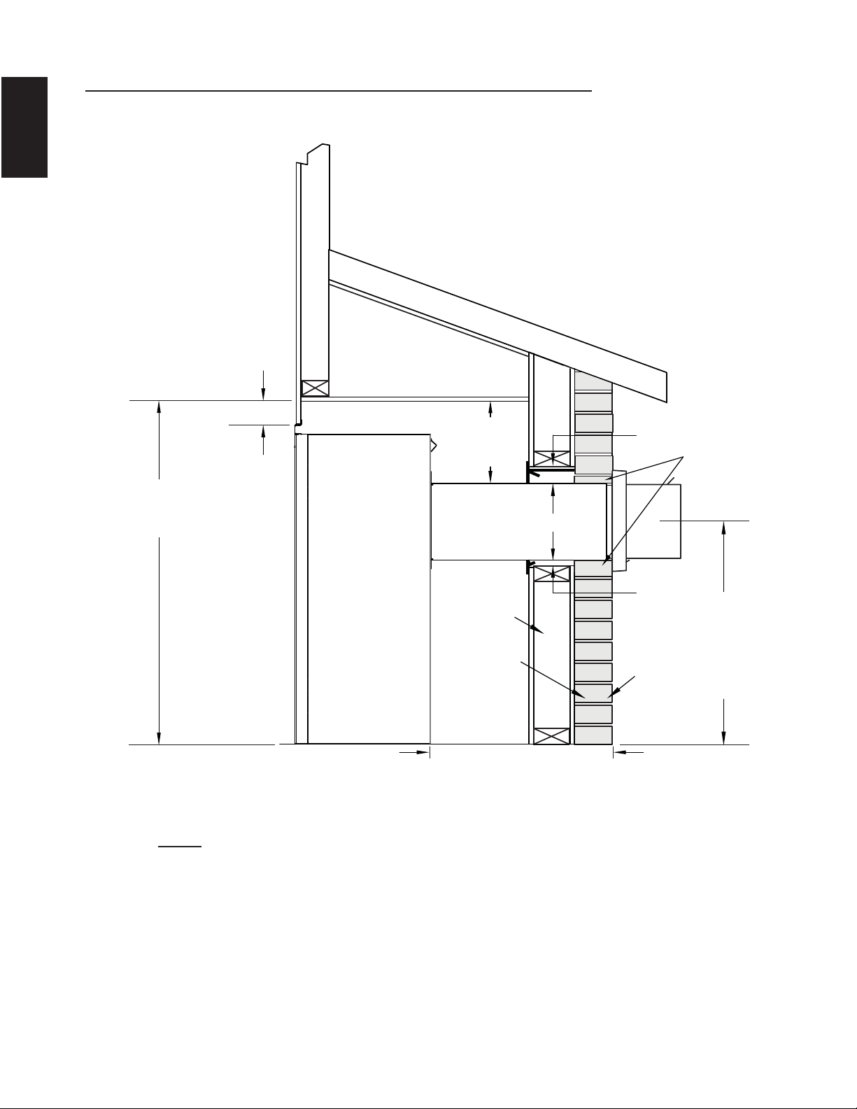
40
W415-1401 / C / 03.18.15
EN
REAR EXIT ENCLOSURE
The appliance requires a minimum enclosure height of 41" (1041mm). For temperature
requirements, the enclosure space around and above the appliance must be left
unobstructed.
B36 MAXIMUM REAR VENT CLEARANCES (EXAMPLE 2)
24"
[610mm]
MINIMUM
PLUS RISE*
COMBUSTIBLE
NON-COMBUSTIBLE
1"
[25mm]
3"
[76mm]
BRICK
0” (0MM) IF
NON-COMBUSTIBLE
FINISHING IS USED
SUCH AS BRICK
AND STONE.
7"
[178mm]
41"
[1041mm]
10"-20"
[254mm-508mm]
VENT RUN
11 1/2"
[292mm]
NOTE: The vent shield is telescopic and must be adjusted to shield the full depth of the
combustible wall penetration.
41
W415-1401 / C / 03.18.15
EN
5.3 GX36 FRAMING
!
WARNING
RISK OF FIRE!
IN ORDER TO AVOID THE POSSIBILITY OF EXPOSED INSULATION OR VAPOUR BARRIER COMING
IN CONTACT WITH THE APPLIANCE BODY, IT IS RECOMMENDED THAT THE WALLS OF THE
APPLIANCE ENCLOSURE BE “FINISHED” (IE: DRYWALL / SHEETROCK), AS YOU WOULD FINISH
ANY OTHER OUTSIDE WALL OF A HOME. THIS WILL ENSURE THAT CLEARANCE TO
COMBUSTIBLES IS MAINTAINED WITHIN THE CAVITY.
DO NOT NOTCH THE FRAMING AROUND THE APPLIANCE STAND-OFFS. FAILURE TO MAINTAIN
AIR SPACE CLEARANCE MAY CAUSE OVER HEATING AND FIRE. PREVENT CONTACT WITH
SAGGING OR LOOSE INSULATION OR FRAMING AND OTHER COMBUSTIBLE MATERIALS. BLOCK
OPENING INTO THE CHASE TO PREVENT ENTRY OF BLOWN-IN INSULATION. MAKE SURE
INSULATION AND OTHER MATERIALS ARE SECURED.
WHEN CONSTRUCTING THE ENCLOSURE ALLOW FOR FINISHING MATERIAL THICKNESS TO
MAINTAIN CLEARANCES. FRAMING OR FINISHING MATERIAL CLOSER THAN THE MINIMUMS
LISTED MUST BE CONSTRUCTED ENTIRELY OF NON-COMBUSTIBLE MATERIALS. MATERIALS
CONSISTING ENTIRELY OF STEEL, IRON, BRICK, TILE, CONCRETE, SLATE, GLASS OR PLASTERS,
OR ANY COMBINATION THEREOF ARE SUITABLE. MATERIALS THAT ARE REPORTED AS PASSING
ASTM E 136, STANDARD TEST METHOD FOR BEHAVIOUR OF MATERIALS IN A VERTICAL TUBE
FURNACE AT 1382° F (750°C) AND UL763 SHALL BE CONSIDERED NON-COMBUSTIBLE
MATERIALS.
MINIMUM CLEARANCE TO COMBUSTIBLES MUST BE MAINTAINED OR A SERIOUS FIRE HAZARD
COULD RESULT.
THE APPLIANCE REQUIRES A MINIMUM ENCLOSURE HEIGHT. MEASURE FROM THE APPLIANCE
BASE.
IF STEEL STUD FRAMING KITS WITH CEMENT BOARD ARE PROVIDED, OR SPECIFIED IN THE
INSTALLATION INSTRUCTIONS. THEY MUST BE INSTALLED.
FINISHING MUST BE DONE USING A NON-COMBUSTIBLE MATERIAL EXTENDING FROM THE TOP
OF THE APPLIANCE SUCH AS NON-COMBUSTIBLE BOARD, CERAMIC TILE, MARBLE, ETC. DO
NOT USE WOOD OR DRYWALL.
ANY FIRE RATED DRYWALL IS NOT ACCEPTABLE.
71.1B
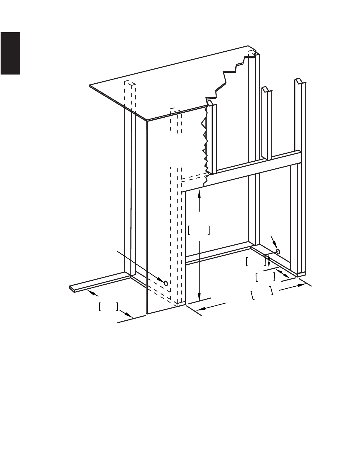
42
W415-1401 / C / 03.18.15
EN
5.3.1 MINIMUM FRAMING DIMENSIONS GX36
35 1/2"
902mm
35"
889mm
1 7/8"
47mm
8"
203mm
16"
406mm
GAS
INLET
LOCATION
ELECTRICAL
CONNECTION
ENCLOSURE
TOP
FINISHING
MATERIAL
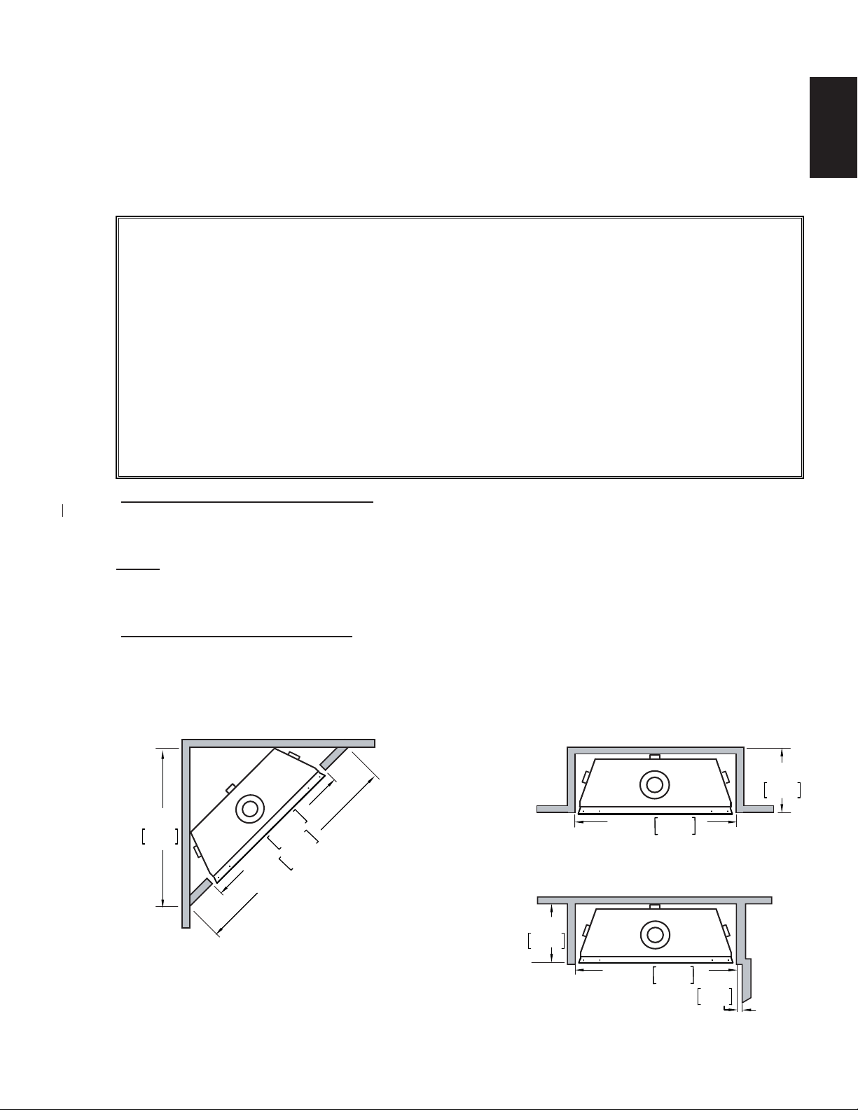
43
W415-1401 / C / 03.18.15
EN
35 1/2"
902mm
49 1/8"
1248mm
31 7/8"
810mm
It is best to frame your appliance after it is positioned and the vent system is installed. Frame to local building
codes.
It is not necessary to install a hearth extension with this appliance.
When roughing in the appliance, raise the appliance to accommodate for the thickness of the fi nished fl oor
materials, i.e. tile, carpeting, hard wood, which if not planned for will interfere with the opening of the lower
access door and the installation of many decorative fl ashing accessories.
Combustible materials may be installed fl ush with the front of the appliance but must not cover any of the black
face-areas of the appliance. Non-combustible material (brick, stone or ceramic tile) may protrude in these areas.
Minimum clearance to combustible construction from appliance and vent surfaces:
Combustible Framing:
- 0" to stand-offs
- 1" (25mm) to bottom and sides of the vent pipe*
- 3" (76mm) to top of the vent pipe*
Combustible Finishing:
- 0" to rear stand offs
- 0" to front face top and sides
Top Exit
- 50 1/2" (1283mm) to combustible enclosure top from base of the appliance
- 54" (1372mm) to ceiling from base of the appliance
Rear Exit
- 44" (1118mm) to combustile enclosure top from base of the appliance
- 54" (1372mm) to ceiling from base of the appliance
*GX36 HORIZONTAL VENT SECTIONS: A minimum of 1" (25mm) at the bottom and sides and 3" (76mm)
at the top of the vent pipe on all horizontal runs to combustibles is required. Use fi restop spacer W010-3440
(supplied).
NOTE: The minimum clearances from the top of the horizontal vent pipe to combustible materials may
be reduced from 3" (76mm) to 2" (51mm) in those installations with a minimum 38" (965mm) vertical
vent rise made immediately off the fi replace collar.
*GX36 VERTICAL VENT SECTIONS: A minimum of 1" (25mm) all around the vent pipe on all vertical runs to
combustibles is required except for clearances in appliance enclosures. Vertical runs within the enclosure must
maintain a 3" (76mm) clearance from combustibles. See "MINIMUM ENCLOSURE CLEARANCES" section.
Use fi restop spacer W500-0096 (not supplied).
INSIDE
CHASE
OUTSIDE
CHASE
SIDE
WALL
16”
406mm
16"
406mm
2"
51mm
35 1/2"
902mm
35 1/2"
902mm
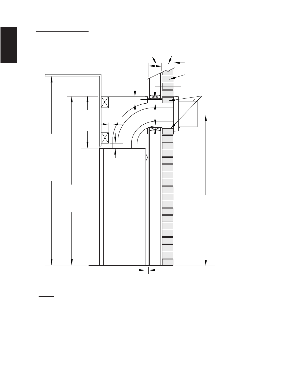
44
W415-1401 / C / 03.18.15
EN
GX36 TOP VENT
3" [76mm]
COMBUSTIBLE
NON-COMBUSTIBLE
BRICK
0” (0MM) IF
NON-COMBUSTIBLE
FINISHING IS USED
SUCH AS BRICK
AND STONE.
3" [76mm]
MINIMUM
3" [76mm]
2"
[51mm]
1"
[25mm]
50 1/2"
[1283mm]
54"
[1372mm]
CEILING
(MIN)
42 1/16"
[1068mm]
MINIMUM
PLUS RISE*
16 1/4"
[412mm]
1"
[25mm]
TOP EXIT ENCLOSURE
The appliance requires a minimum enclosure height of 50 1/2" (1282mm). For temperature
requirements, the enclosure space around and above the appliance must be left
unobstructed.
NOTE: The vent shield is telescopic and must be adjusted to shield the full depth of the
combustible wall penetration.
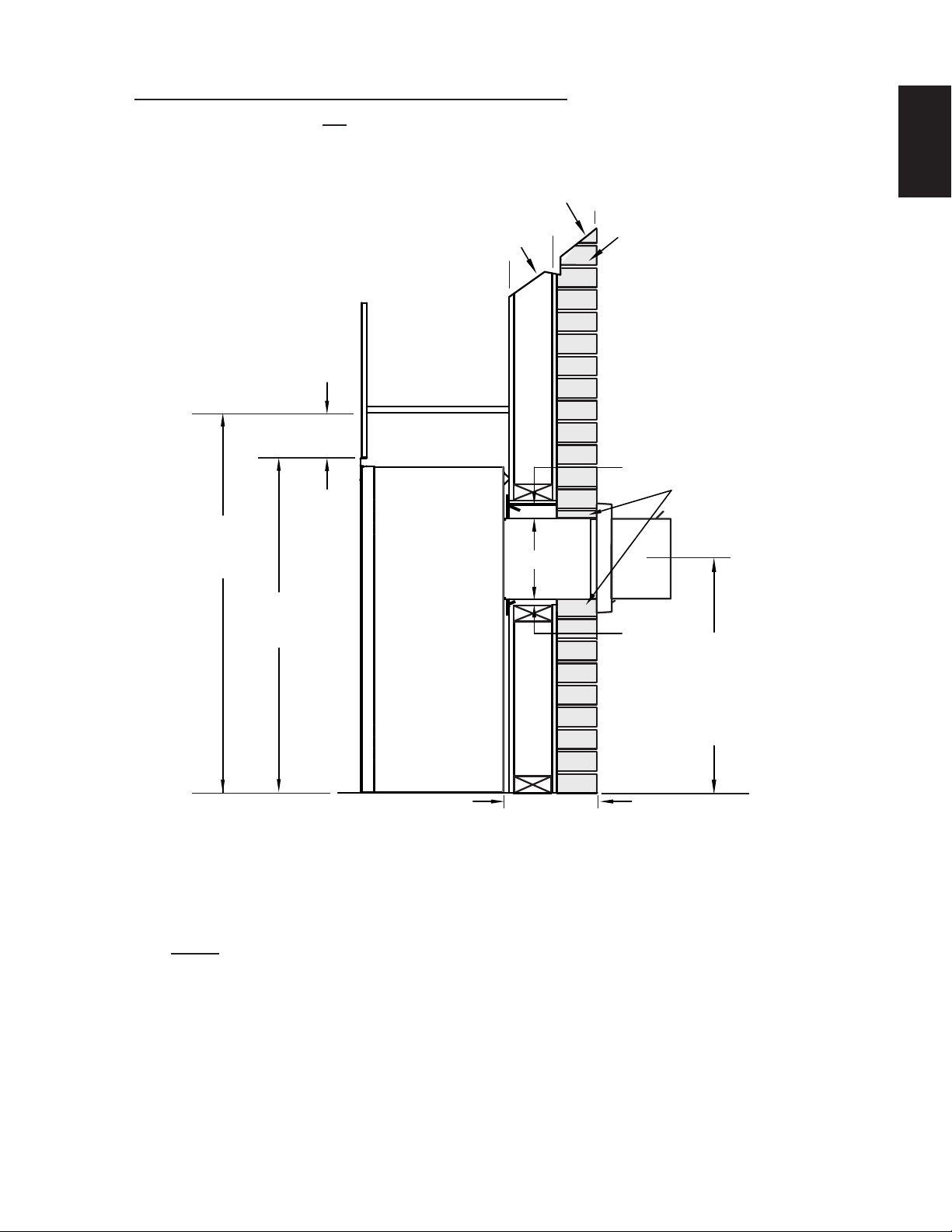
45
W415-1401 / C / 03.18.15
EN
GX36 MINIMUM REAR VENT CLEARANCES
REAR EXIT ENCLOSURE
The appliance requires a minimum enclosure height of 44" (1118mm). For temperature
requirements, the enclosure space around and above the appliance must be left
unobstructed.
24"
[610mm]
MINIMUM
PLUS RISE*
COMBUSTIBLE
NON-COMBUSTIBLE
1"
[25mm]
3"
[76mm]
BRICK
0” (0MM) IF
NON-COMBUSTIBLE
FINISHING IS USED
SUCH AS BRICK
AND STONE.
10"
[254mm]
44"
[1118mm]
1"-10"
[25mm-254mm]
VENT RUN
34 1/16"
[865mm]
NOTE: The vent shield is telescopic and must be adjusted to shield the full depth of the
combustible wall penetration.
For rear vent termination not exceeding 10" (254mm) of horizontal vent run.
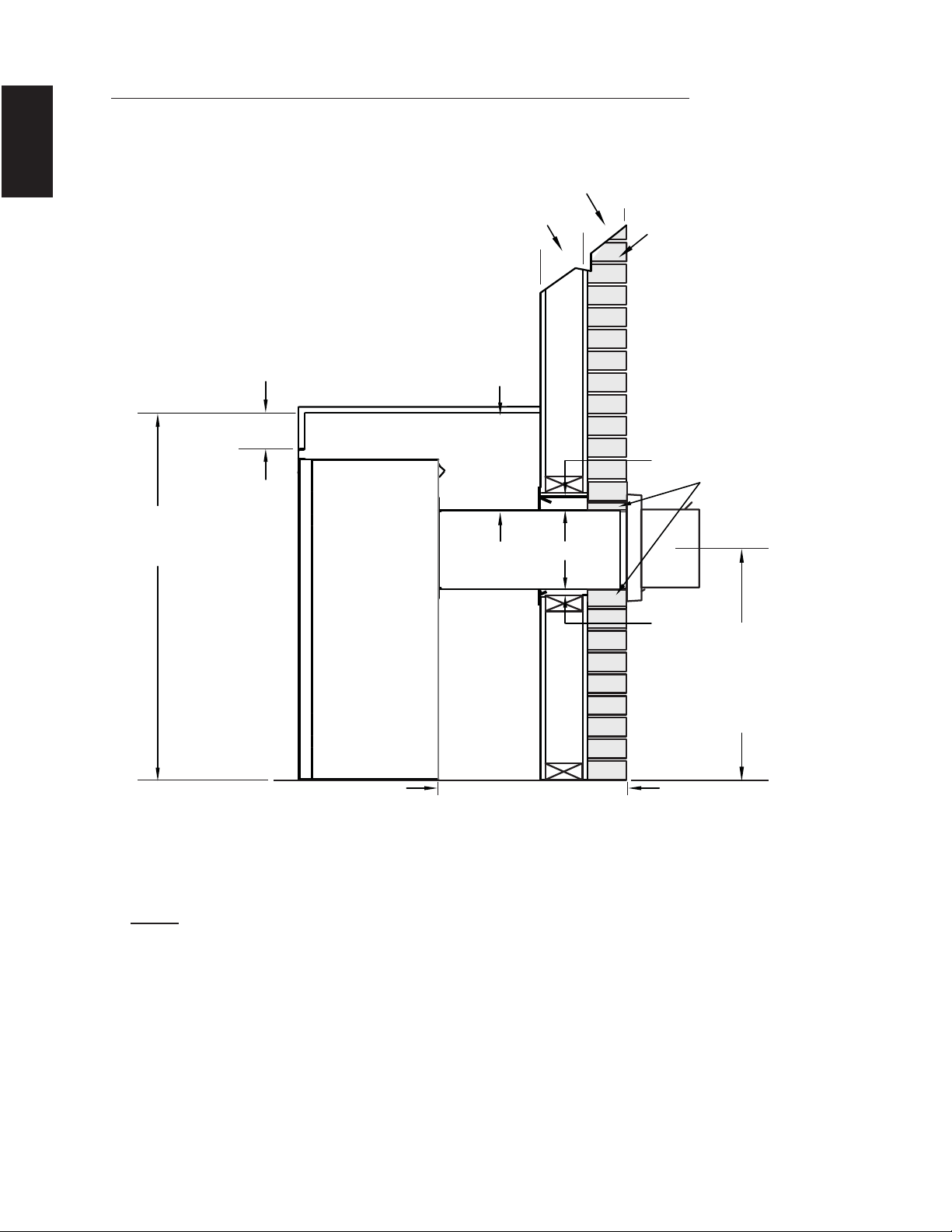
46
W415-1401 / C / 03.18.15
EN
GX36 MAXIMUM REAR VENT CLEARANCES (EXAMPLE 1)
REAR EXIT ENCLOSURE
The appliance requires a minimum enclosure height of 44" (1118mm). For temperature
requirements, the enclosure space around and above the appliance must be left
unobstructed.
24"
[610mm]
MINIMUM
PLUS RISE*
COMBUSTIBLE
NON-COMBUSTIBLE
1"
[25mm]
3"
[76mm]
BRICK
0” (0MM) IF
NON-COMBUSTIBL
FINISHING IS USED
SUCH AS BRICK
AND STONE.
10"
[254mm]
44"
1
118mm]
10"-20"
[254mm-508mm]
VENT RUN
14 1/2"
[368mm]
NOTE: The vent shield is telescopic and must be adjusted to shield the full depth of the
combustible wall penetration.
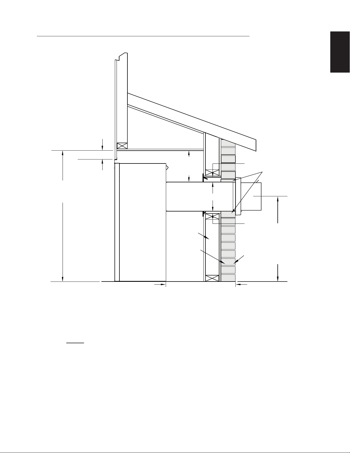
47
W415-1401 / C / 03.18.15
EN
GX36 MAXIMUM REAR VENT CLEARANCES (EXAMPLE 2)
REAR EXIT ENCLOSURE
The appliance requires a minimum enclosure height of 44" (1118mm). For temperature
requirements, the enclosure space around and above the appliance must be left
unobstructed.
24"
[610mm]
MINIMUM
PLUS RISE*
COMBUSTIBLE
NON-COMBUSTIBLE
1"
[25mm]
3"
[76mm]
BRICK
0” (0MM) IF
NON-COMBUSTIBLE
FINISHING IS USED
SUCH AS BRICK
AND STONE.
10"
[254mm]
44"
[1118mm]
10"-20"
[254mm-508mm]
VENT RUN
14 1/2"
[368mm]
NOTE: The vent shield is telescopic and must be adjusted to shield the full depth of the
combustible wall penetration.

48
W415-1401 / C / 03.18.15
EN
APPLIANCE
RECESS OR
ALCOVE
AREA
NOTE: Recesses or alcoves above the appliance can be made as deep as desired provided the minimum
clearances to combustibles are maintained.
Non-combustible material can be used, provided the minimum clearances to combustible materials are applied.
The minimum enclosure volume must be increased by no less than the volume of the recess. This adjustment
can be made by increasing any or all of the height, width and depth of the enclosure.
71.2
ENCLOSURE
AREA
5.4 ALCOVE CLEARANCES
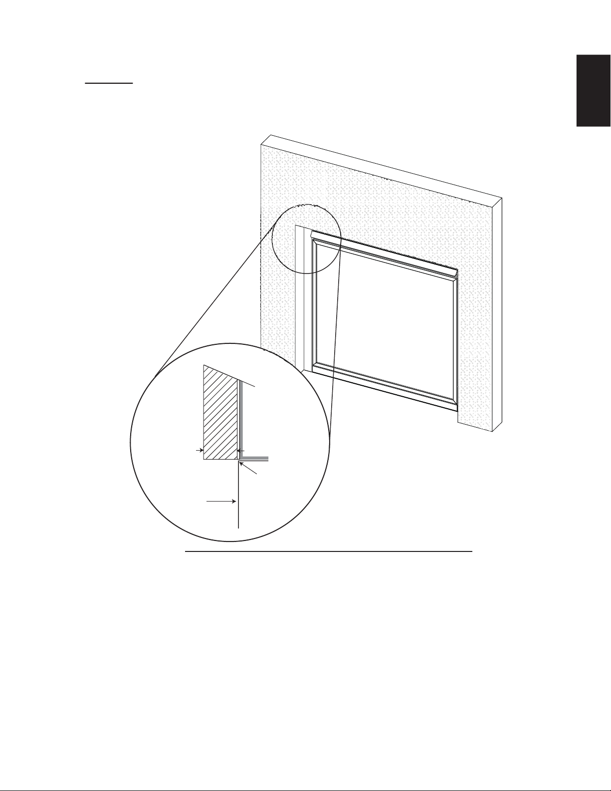
49
W415-1401 / C / 03.18.15
EN
5.5 NON-COMBUSTIBLE FACING MATERIAL
71.7
WARNING: Non-combustible facing material must not project more than 4” (102mm) from the face of the door
(all three sides). If greater projections are desired, increase the clearance to the sides and top by 2” (51mm)
for every additional 1” (25mm) of projection. If using an optional surround, the same rule applies, starting from
the top of the surround. Ensure clearances are maintained for surround removal, as it must lift off the appli-
ance for maintenance.
GLASS
DOOR
TOP OF
APPLIANCE
4" (102mm)
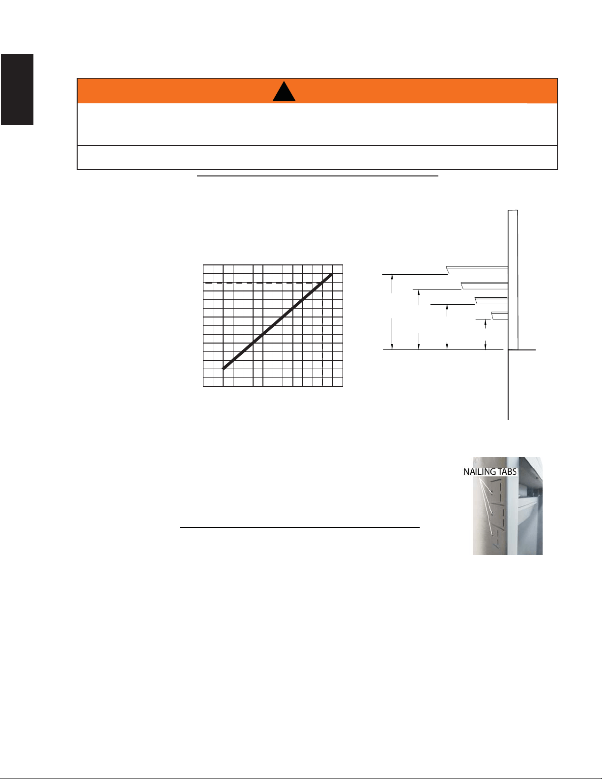
50
W415-1401 / C / 03.18.15
EN
Combustible Mantel clearance can vary according to the Mantel depth. Use the graph
to help evaluate the clearance needed. These same requirements apply to any
combustibles protruding on either side of the appliance.
TOP OF APPLIANCE
8" [203mm]
MANTEL
8"
[203mm]
6"
[152mm]
4"
[102mm]
2" [51mm]
2" [51mm]
4" [102mm]
6" [152mm]
!
WARNING
RISK OF FIRE, MAINTAIN ALL SPECIFIED AIR SPACE CLEARANCES TO COMBUSTIBLES. FAILURE
TO COMPLY WITH THESE INSTRUCTIONS MAY CAUSE A FIRE OR CAUSE THE APPLIANCE TO
OVERHEAT. ENSURE ALL CLEARANCES (I.E. BACK, SIDE, TOP, VENT, MANTEL, FRONT, ETC.) ARE
CLEARLY MAINTAINED.
WHEN USING PAINT OR LACQUER TO FINISH THE MANTEL, THE PAINT OR LACQUER MUST BE
HEAT RESISTANT TO PREVENT DISCOLOURATION.
73.1
5.6 MINIMUM MANTEL CLEARANCES
0
$
1
7
(
/
+
(
,
*
+
7
2" (51mm)
24681012
MANTEL DEPTH (INCHES)
4" (102mm)
6" (152mm)
10" (254mm)
12" (305mm)
5.7 NAILING TAB INSTALLATION
55.2
A. To determine the fi nal location and where to bend the nailing tabs you must
fi rst determine the thickness of your fi nishing material (i.e. drywall). This will
determine the dimension from the front edge of the corner post to the nailing
tab. Once the desired tab has been choosen, bend and secure to the framing.
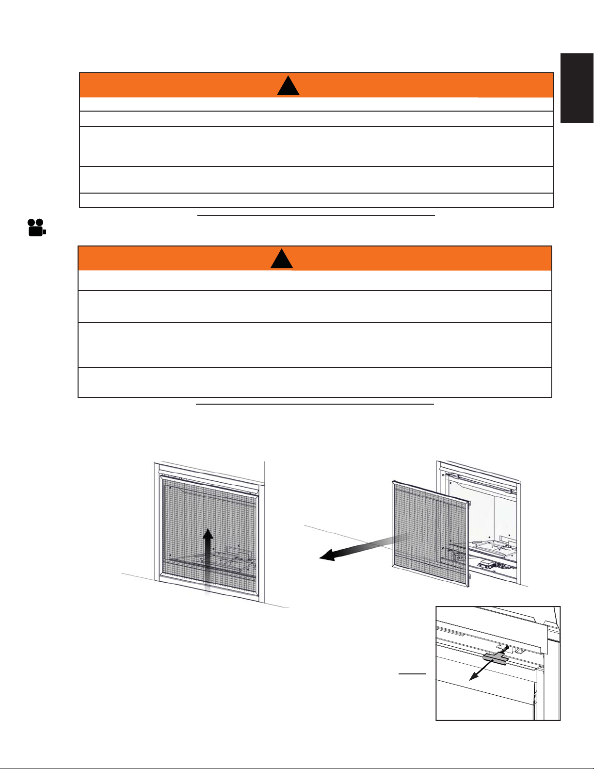
51
W415-1401 / C / 03.18.15
EN
6.0 FINISHING
!
WARNING
RISK OF FIRE!
NEVER OBSTRUCT THE FRONT OPENING OF THE APPLIANCE.
THE FRONT OF THE APPLIANCE MUST BE FINISHED WITH ANY NON-COMBUSTIBLE MATERIALS
SUCH AS BRICK, MARBLE, GRANITE, ETC., PROVIDED THAT THESE MATERIALS DO NOT GO
BELOW THE SPECIFIED DIMENSION AS ILLUSTRATED.
DO NOT STRIKE, SLAM OR SCRATCH GLASS. DO NOT OPERATE APPLIANCE WITH GLASS
REMOVED, CRACKED, BROKEN OR SCRATCHED.
FACING AND/OR FINISHING MATERIAL MUST NEVER OVERHANG INTO THE APPLIANCE OPENING.
72.1A
A barrier designed to reduce the risk of burns from the hot viewing glass is provided with the
appliance and must be installed.
Before the glass door can be removed, the safety screen must be removed. Lift the safety screen off the 4
pins, tilt the top forward and remove from the appliance.
Leave a hand on the glass door during entire door removal. The glass door is
secured to the fi rebox with two spring latches along the top and two along the
bottom. Pull the handles of the latches forward, then lift the latches out from
the door frame to release the top of the door. Repeat the same step for the two
bottom latches. Next, pivot the door forward until the top edge clears the front of
the appliance. Carefully grip the sides of the door lifting it off the appliance.NOTE:
These spring latches make up the spring relief system for the appliance.
Ensure the door opens freely and closes sealed.
Reverse these steps to re-install the door and safety screen. Ensure safety screen
is installed correctly.
6.1 SAFETY SCREEN & DOOR REMOVAL / INSTALLATION
!
WARNING
GLASS MAY BE HOT, DO NOT TOUCH GLASS UNTIL COOLED.
THE DOOR LATCHES ARE PART OF A SAFETY RELIEF SYSTEM AND MUST BE PROPERLY
ENGAGED. DO NOT OPERATE THE APPLIANCE WITH LATCHES DISENGAGED.
FACING AND/OR FINISHING MATERIALS MUST NOT INTERFERE WITH AIR FLOW THROUGH AIR
OPENINGS, LOUVRES OPENINGS, OPERATION OF LOUVRES OR DOORS OR ACCESS FOR
SERVICE. OBSERVE ALL CLEARANCES WHEN APPLYING COMBUSTIBLE MATERIALS.
BEFORE DOOR IS REMOVED TURN THE APPLIANCE OFF AND WAIT UNTIL APPLIANCE IS COOL TO
THE TOUCH. DOORS ARE HEAVY AND FRAGILE SO HANDLE WITH CARE.
75.1
SAF
ETY SCREEN
S
A
FETY SCREEN
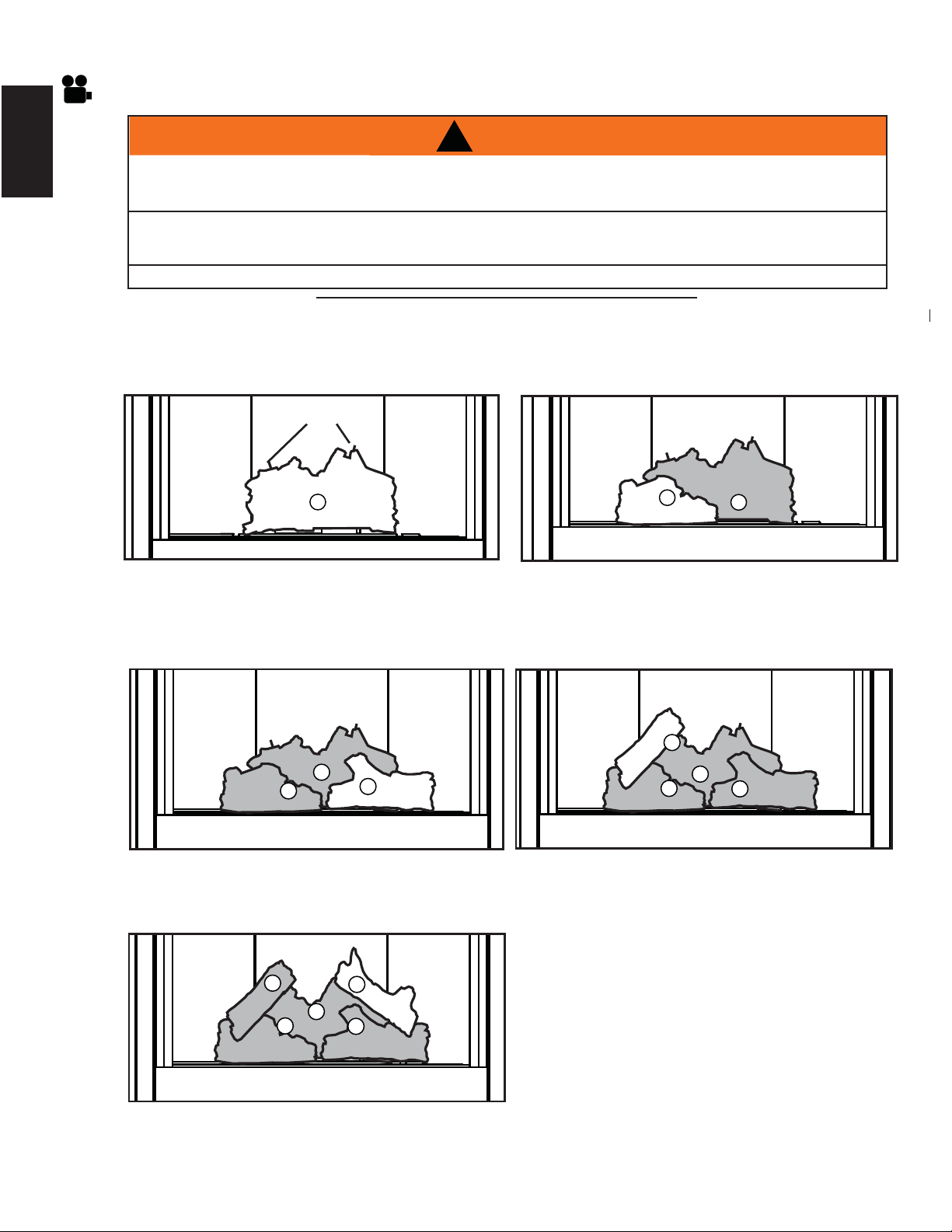
52
W415-1401 / C / 03.18.15
EN
C. Position the right log (W135-0545) onto the
two studs located on the right side of the log
support.
D. Place the left crossover log (W135-0546) onto
the pin located in the left side of the rear log,
allow it to rest in the notch of the left log.
B
A
C
B
A
C
D
6.2 LOG PLACEMENT
PHAZER
TM
logs and glowing embers exclusive to Napoleon, provide a unique and realistic glowing effect that is
different in every installation. Take the time to carefully position the glowing embers for a maximum glowing effect.
Log colours may vary. During the initial use of the appliance, the colours will become more uniform as colour
pigments burn in during the heat activated curing process.
A. Place the rear log (W135-0588) fi rmly onto
the two studs at the rear of the support tray.
Ensure the log sits fl at and does not cover
the pilot opening. Place two pins in the holes
located on the top rear of the rear log.
B. Place the left log (W135-0544) onto the two
studs located on the left side of the log support.
!
WARNING
FAILURE TO POSITION THE LOGS IN ACCORDANCE WITH THESE DIAGRAMS OR FAILURE TO USE
ONLY LOGS SPECIFICALLY APPROVED WITH THIS APPLIANCE MAY RESULT IN PROPERTY
DAMAGE OR PERSONAL INJURY.
LOGS MUST BE PLACED IN THEIR EXACT LOCATION IN THE APPLIANCE. DO NOT MODIFY THE
PROPER LOG POSITIONS, SINCE APPLIANCE MAY NOT FUNCTION PROPERLY AND DELAYED
IGNITION MAY OCCUR.
THE LOGS ARE FRAGILE AND SHOULD BE HANDLED WITH CARE.
76.1A
B
A
A
PINS
E. Place the right crossover log (W135-0589)
onto the two remaining pins.
B
A
C
D
E
F. Reinstall the door and safety screen.
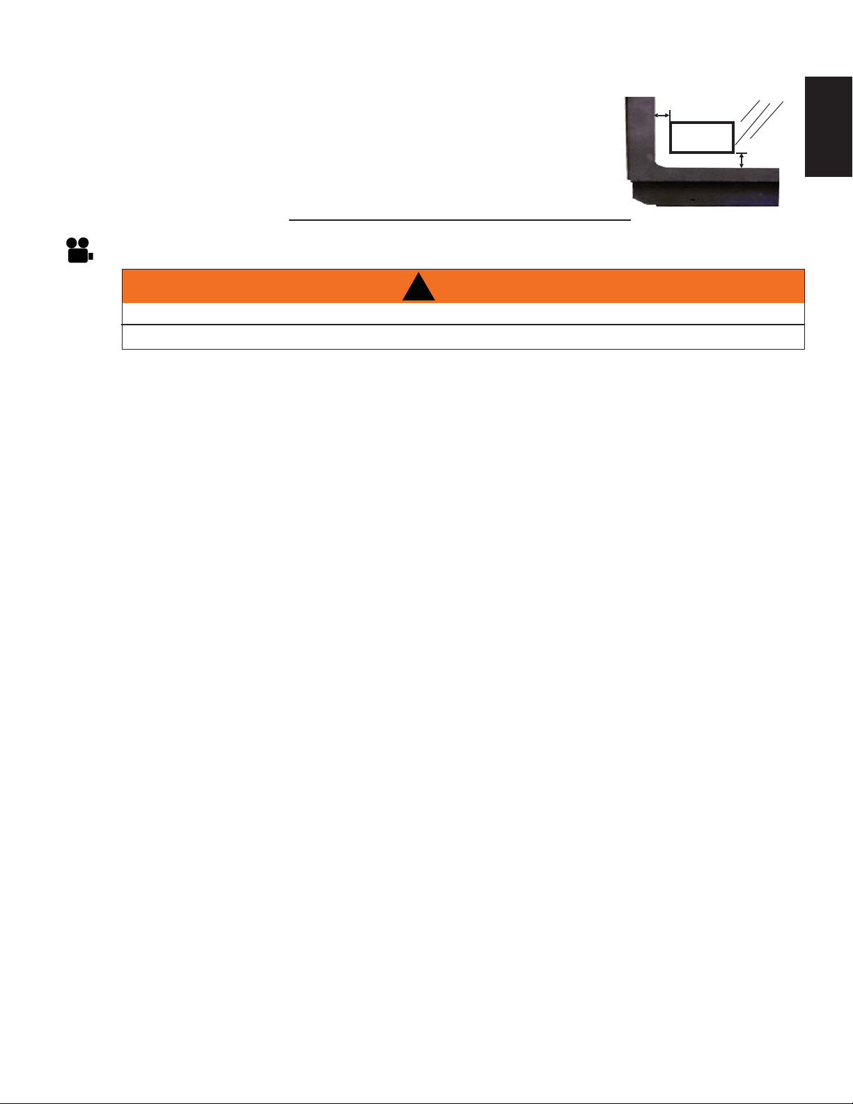
53
W415-1401 / C / 03.18.15
EN
6.3 LOGO PLACEMENT
97.1A
Remove the backing of the logo supplied and place on the glass viewing door,
as indicated.
½"(12.7mm)
LOGO
½"(12.7mm)
6.4 BATTERY BACK-UP INSTALLATION
A. Turn the gas and electrical power off to the appliance, before beginning installation.
B. Locate the battery housing supplied in the manual baggie.
C. Install four “AA” batteries (not supplied) into the battery housing, ensure the positive and negative
ends correspond with those identifi ed on the holder. (To open the battery housing, slide the back piece
upwards and off of the battery housing).
D. Remove the safety screen to easily access the control compartment.
E. Attach the wire labelled “BATTERY” from the wiring harness, located in the control compartment of the
appliance, to the battery housing.
F. Place the battery housing into the control compartment, ensure that the battery housing is placed in a
clean and easily accessible location.
G. Reinstall the safety screen. The safety screen must be installed at all times during the appliance
operation.
H. Turn the gas and electrical power back on to begin operating the appliance.
!
WARNING
ENSURE THE GAS AND ELECTRICAL POWER IS TURNED OFF TO THE APPLIANCE.
APPLIANCE MAY BE HOT, DO NOT SERVICE UNTIL THE APPLIANCE HAS COOLED.
NOTE: In the event of a power failure your appliance can be operated using the battery back-up supplied.
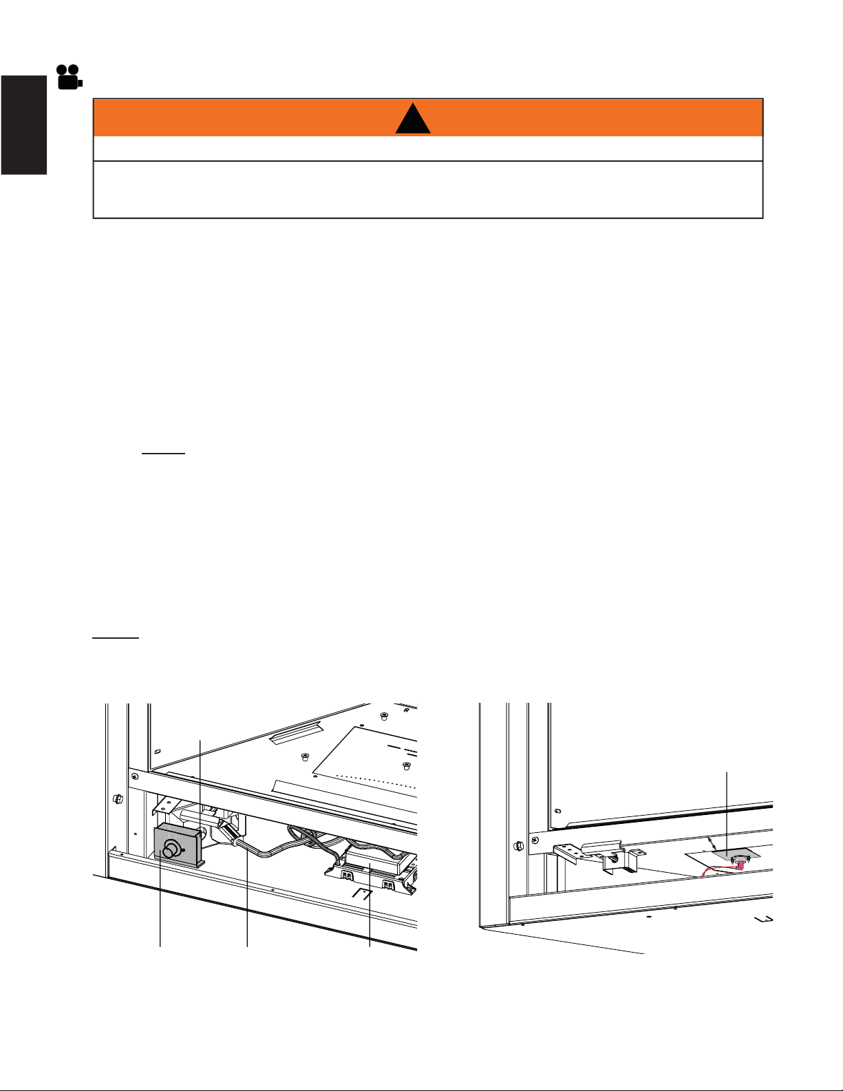
54
W415-1401 / C / 03.18.15
EN
A. Remove the screen by lifting it up and off of the appliance, refer to, "SAFETY SCREEN / DOOR
REMOVAL AND INSTALLATION " section.
B. If equipped with electronic ignition, unplug the control module transformer and lift the control module
from the bottom of the appliance, move both the control module and transformer off to one side to
ease installation of the blower.
C. Remove the two adhesive backing strips from the velcro strips located on the fan mounting bracket of
the blower.
D. Attach the two 1/4” connectors (black and white) from the wire harness to the thermodisc.
E. Attach the two 1/4” connectors (black and red) from the wire harness to the blower.
F. Pivot the blower into the bottom of the appliance, center it on the left side wall of the outer shell. Press
the blower fi rmly against the outer shell so the adhesive sticks to the appliance.
G. NOTE: ENSURE ALL WIRES REMAIN CLEAR OF THE BLOWER.
H. Place the control module back into it’s original position. Ensure the transformer is plugged into the
rear outlet of the electrical box, refer to Figure 1.
I. Remove the adhesive backing strip from the velcro strip located on the variable speed switch (VSS).
Place the VSS fi rmly into position on the front left corner of the base of the outer shell, refer to Figure
1. Plug the connector from the VSS to the matching connection on the wire harness.
J. Position the magnetic thermal disc bracket on the fi rebox base approximately 4” (101.6mm) from the
front of the appliance, refer to Figure 2. Ensure the wire harness is properly attached.
K. Plug the power cord from the blower into the electrical box, refer to Figure 1.
NOTE: The blower is thermally activated, so when it is turned on, it will automatically start
approximately 15 minutes after lighting the appliance and will run for approximately 30 minutes after
the appliance has been turned off.
!
WARNING
ENSURE THE UNIT IS COMPLETELY COOL BEFORE STARTING INSTALLATION
TO AVOID DANGER OF SUFFOCATION KEEP THE PACKAGING BAG AWAY FROM BABIES AND
CHILDREN. DO NOT USE IN CRIBS, BED, CARRIAGES OR PLAY PENS. THIS BAG IS NOT A TOY.
KNOT BEFORE THROWING AWAY.
VARIABLE
SPEED
SWITCH (VSS)
BLOWER
POWER
CORD
CONTROL
MODULE
ELECTRICAL
BOX
THERMAL DISK
BRACKET
4” (101.6mm)
FIGURE 2FIGURE 1
6.5 BLOWER INSTALLATION
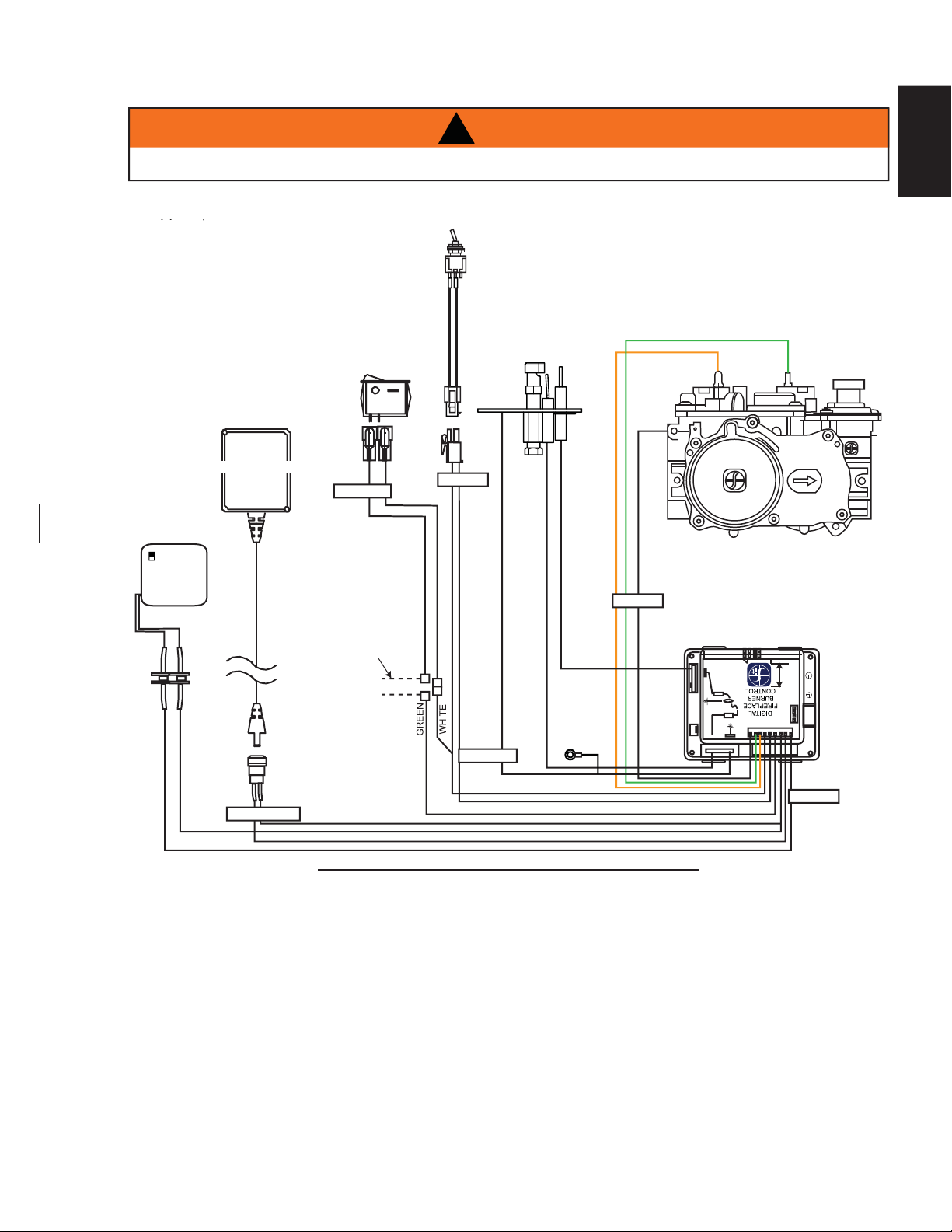
55
W415-1401 / C / 03.18.15
EN
6.6 WIRING DIAGRAM (ELECTRONIC)
69.7
!
WARNING
DO NOT WIRE 110 VOLTS TO THE VALVE OR WALL SWITCH.
ON / OFF
SWITCH
ACS/IPI
SWITCH
BATTERY
HOUSING
(SUPPLIED IN
MANUAL BAGGIE)
GROUND
DFC
VALVE
ORANGE
GREEN
GROUND
EYELET
ON / OFF
IPI / CPI
DISCONNECT THESE
CONNECTIONS TO THE
ON/OFF SWITCH AND
CONNECT TO AN
OPTIONAL THERMOSTAT.
IPI BOARD
DC SUPPLY
TRANSFORMER
VALVE
ELECTRONIC
OFF ON
This appliance comes equipped with a battery back-up. If this back-up is used, install 4AA batteries (not
supplied) into the holder and connect to the wire harness.
This appliance comes with a battery back-up. If this back-up is used, install 4AA batteries (not supplied) into the
holder and connect to the wire harness.
(OPTIONAL)
BATTERY
HOUSING
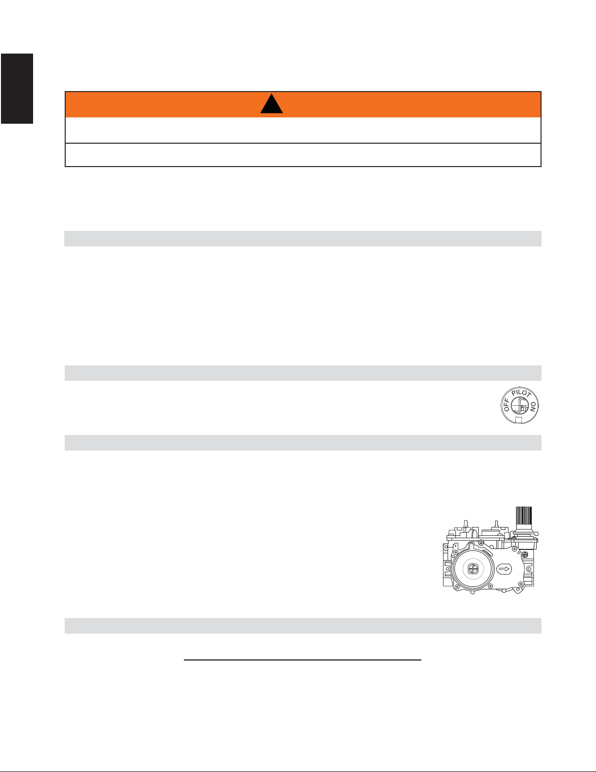
56
W415-1401 / C / 03.18.15
EN
7.0 OPERATION
7.1 B36NTRE/GX36NTRE & B36PTRE/GX36PTRE (ELECTRONIC)
Ensure that a continuous gas fl ow is at the burner before installing the door. When lit for the fi rst time, the
fi replace will emit an odor for a few hours. This is a normal temporary condition caused by the “burn-in” of
paints and lubricants used in the manufacturing process and will not occur again. After extended periods of
non-operation such as following a vacation or a warm weather season, the fi replace may emit a slight odor for
a few hours. This is caused by dust particles in the heat exchanger burning off. In both cases, open a window
to suffi ciently ventilate the room.
FOR YOUR SAFETY READ BEFORE LIGHTING:
A. Do not turn on if children or other at risk individuals are near the fi replace.
B. This fi replace is equipped with a pilot which must be lit by hand while following these instructions
exactly.
C. Before operating smell all around the fi replace area for gas and next to the fl oor because some gas is
heavier than air and will settle on the fl oor.
D. Use only your hand to turn the gas control knob. Never use tools. If the knob will not turn by hand, do
not try to repair it. Call a qualifi ed service technician. Force or attempted repair may result in a fi re or
explosion.
E. Do not use this fi replace if any part has been under water. Immediately call a qualifi ed service
technician to inspect the fi replace and replace any part of the control system and any gas control
which has been underwater.
WHAT TO DO IF YOU SMELL GAS:
• Turn off all gas to the fi replace.
• Open windows.
• Do not try to light any appliance.
• Do not touch any electric switch; do not use
any phone in your building.
• Immediately call your gas supplier from
a neighbour’s phone. Follow the gas
supplier’s instructions.
• If you cannot reach your gas supplier,
call the fi re department.
LIGHTING INSTRUCTIONS:
1. Stop! Read the above safety information on this label
2. Remove batteries from the transmitter.
3. Turn off all electrical power to the fi replace.
4. This fi replace is equipped with an ignition device which automatically lights the pilot. Do not try to
light the pilot by hand.
5. Open the glass door.
6. Turn manual shutoff valve clockwise to off. Located behind the access panel.
7. Wait fi ve (5) minutes to clear out any gas. If you smell gas including near the
fl oor, STOP! Follow “B” in the above safety information on this label. If you
don’t smell gas go to the next step.
8. Turn manual shutoff valve counter-clockwise to on.
9. Close the glass door.
10. Turn on all electric power to the fi replace and re-install batteries into the
transmitter.
11. Push the “ON” button on the transmitter. You should here an audible beep from
the receiver which indicates communication (refer to Fireplace Operation for
remote activation).
1. Turn off all electric power to the fi replace if service is to be performed.
2. Push in gas control knob slightly and turn clockwise to off. Do not force.
TO TURN OFF GAS:
GAS KNOB
47.3A
IF YOU DO NOT FOLLOW THESE INSTRUCTIONS EXACTLY, A FIRE OR EXPLOSION MAY RESULT
CAUSING PROPERTY DAMAGE, PERSONAL INJURY OR LOSS OF LIFE.
ALWAYS LIGHT THE PILOT WHETHER FOR THE FIRST TIME OR IF THE GAS SUPPLY HAS RUN OUT WITH
THE GLASS DOOR OPENED OR REMOVED.
!
WARNING
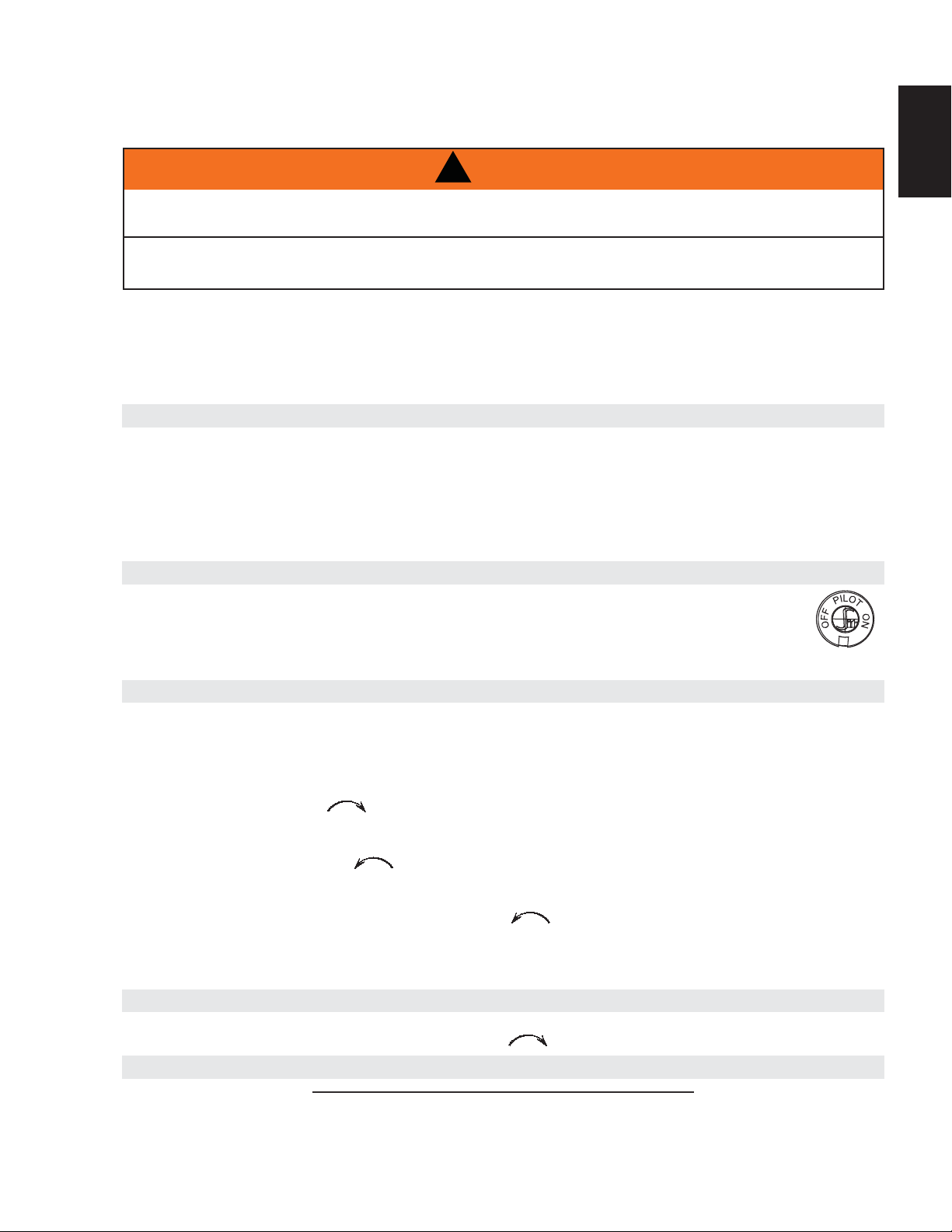
57
W415-1401 / C / 03.18.15
EN
Ensure that a continuous gas flow is at the burner before installing the door. When lit for the first time, the appliance will
emit an odor for a few hours. This is a normal temporary condition caused by the "burn-in" of paints and lubricants used in
the manufacturing process and will not occur again.
A
fter extended periods of non-operation such as following a vacation or a warm weather season, the appliance may emit a
slight odor for a few hours. This is caused by dust particles in the heat exchanger burning off. In both cases, open a
window to sufficiently ventilate the room.
FOR YOUR SAFETY READ BEFORE LIGHTING:
A. This appliance is equipped with a pilot which must be lit by hand while following these instructions exactly.
B. Before operating smell all around the appliance area for gas and next to the floor because some gas is heavier than
air and will settle on the floor.
C. Use only your hand to turn the gas control knob. Never use tools. If the knob will not turn by hand, do not try to
repair it. Call a qualified service technician. Force or attempted repair may result in a fire or explosion.
D. Do not use this appliance if any part has been under water. Immediately call a qualified service technician to inspect
the appliance and replace any part of the control system and any gas control which has been under water.
Turn off all gas to the appliance.
Open windows.
Do not try to light any appliance.
Do not touch any electric switch; do not use any
phone in your building.
GAS KNOB
WARNING: The gas valve has an interlock device which will not allow the pilot burner to be lit until the thermo-
couple has cooled. Allow approximately 60 seconds for the thermocouple to cool.
When lighting and re-lighting, the gas knob cannot be turned from pilot to off unless the knob is depressed slightly.
1. Stop! Read the above safety information on this label.
2. Turn off all electric power to the appliance.
3. Turn the gas knob clockwise to off.
4. Wait five (5) minutes to clear out any gas. If you smell gas including near the floor. Stop! Follow "B" in the
above safety information on this label. If you don't smell gas go the next step.
5. Turn gas knob counter-clockwise to pilot.
6. Depress slightly and hold gas knob while lighting the pilot with the push button igniter. Keep knob depressed for one
minute, then release. If pilot does not continue to burn, repeat steps 3 through 5.
7. With pilot lit, depress and turn gas knob counter-clockwise to on.
8. If equipped with remote on-off switch / thermostat, main burner may not come on when you turn valve to on. Remote
switch must be in the on position to ignite burner.
9. Turn on all electric power to the appliance.
1. Turn off all electric power to the appliance if service is to be performed.
2. Push in gas control knob slightly and turn clockwise to off. Do not force.
Immediately call your gas supplier from a
neighbor's phone. Follow the gas
supplier's instructions.
If you cannot reach your gas supplier,
call the fire department.
WHAT TO DO IF YOU SMELL GAS:
LIGHTING INSTRUCTIONS:
TO TURN OFF GAS
TURN THE CONTROL VALVE TO THE OFF POSITION WHEN HEATER IS NOT IN USE.
47.2
IF YOU DO NOT FOLLOW THESE INSTRUCTIONS EXACTLY, A FIRE OR EXPLOSION MAY RESULT
CAUSING PROPERTY DAMAGE, PERSONAL INJURY OR LOSS OF LIFE.
ALWAYS LIGHT THE PILOT WHETHER FOR THE FIRST TIME OR IF THE GAS SUPPLY HAS RUN OUT WITH
THE GLASS DOOR OPENED OR REMOVED.
!
WARNING
8.0 OPERATION
8.1 B36NTR/GX36NTR & B36PTR/GX36PTR (MILLIVOLT)
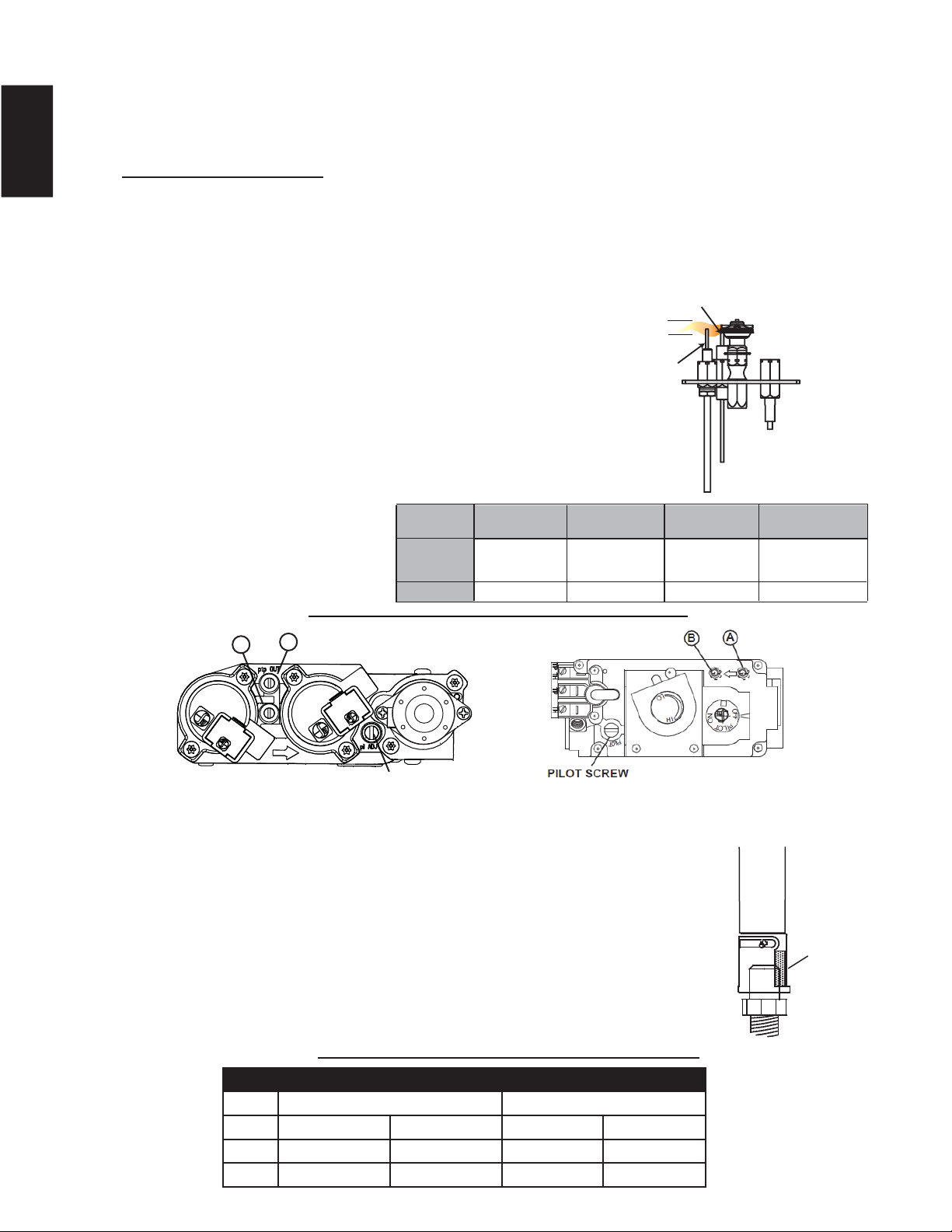
58
W415-1401 / C / 03.18.15
EN
VENTURI ADJUSTMENT CHART
B36 GX36
FUEL TOP REAR TOP REAR
NG 1/16" (1.5mm) 1/16" (1.5mm) 1/4" (6.3mm) 1/4" (6.3mm)
LP 3/8" (9.5mm) 3/8" (9.5mm) 3/8" (9.5mm) FULL OPEN
This appliance has an air shutter that has been factory set open according
to the chart below:
Regardless of venturi orientation, closing the air shutter will cause a more
yellow flame, but can lead to carboning. Opening the air shutter will cause a
more blue flame, but can cause flame lifting from the burner ports. The
flame may not appear yellow immediately; allow 15 to 30 minutes for the
final flame colour to be established.
AIR SHUTTER ADJUSTMENT MUST ONLY BE DONE BY A QUALIFIED
INSTALLER!
AIR
SHUTTER
OPENING
VENTURI
BURNER
ORIFICE
49.1
9.0 ADJUSTMENT
9.1 PILOT BURNER ADJUSTMENT
9.2 VENTURI ADJUSTMENT
ELECTRONIC
MILLIVOLT
Adjust the pilot screw to provide properly sized fl ame. Turn in a
clockwise direction to reduce the gas fl ow.
Check Pressure Readings:
Inlet pressure can be checked by turning screw (A) counter-
clockwise 2 or 3 turns and then placing pressure gauge tubing
over the test point. Gauge should read as described on the chart
below. Check that main burner is operating on “HI”.
Outlet pressure can be checked the same as above using
screw (B). Gauge should read as described on the chart
below. Check that main burner is operating on “HI”.
AFTER TAKING PRESSURE READINGS, BE SURE TO
TURN SCREWS CLOCKWISE FIRMLY TO RESEAL. DO
NOT OVERTORQUE.
Leak test with a soap and water solution.
Prior to pilot adjustment, ensure that the pilot assembly
has not been painted. If overspray or painting of the pilot
assembly has occurred remove the paint from the pilot
assembly, or replace. Fine emery
cloth or sandpaper can be used to
remove the paint from the pilot hood,
electrode and fl ame sensor.
39.1C
A
B
PILOT SCREW
FLAME MUST ENVELOP
UPPER 3/8” (9.5mm) TO 1/2”
(12.7mm) OF FLAME SENSOR
PILOT
BURNER
ELECTRODE
FLAME
SENSOR
3/8” - 1/2”
(9.5mm - 12.7mm)
Pressure
Inlet
Outlet
Natural Gas
(inches)
Natural Gas
(millibars)
Propane
(inches)
Propane
(millibars)
7"
(MIN. 4.5")
3.5"
13"
(MIN. 11")
10"
17.4mb
(MIN. 11.2mb)
8.7mb
32.4mb
(MIN. 27.4mb)
24.9mb
ELECTRONIC
ILLUSTRATED
A
B
PILOT SCREW
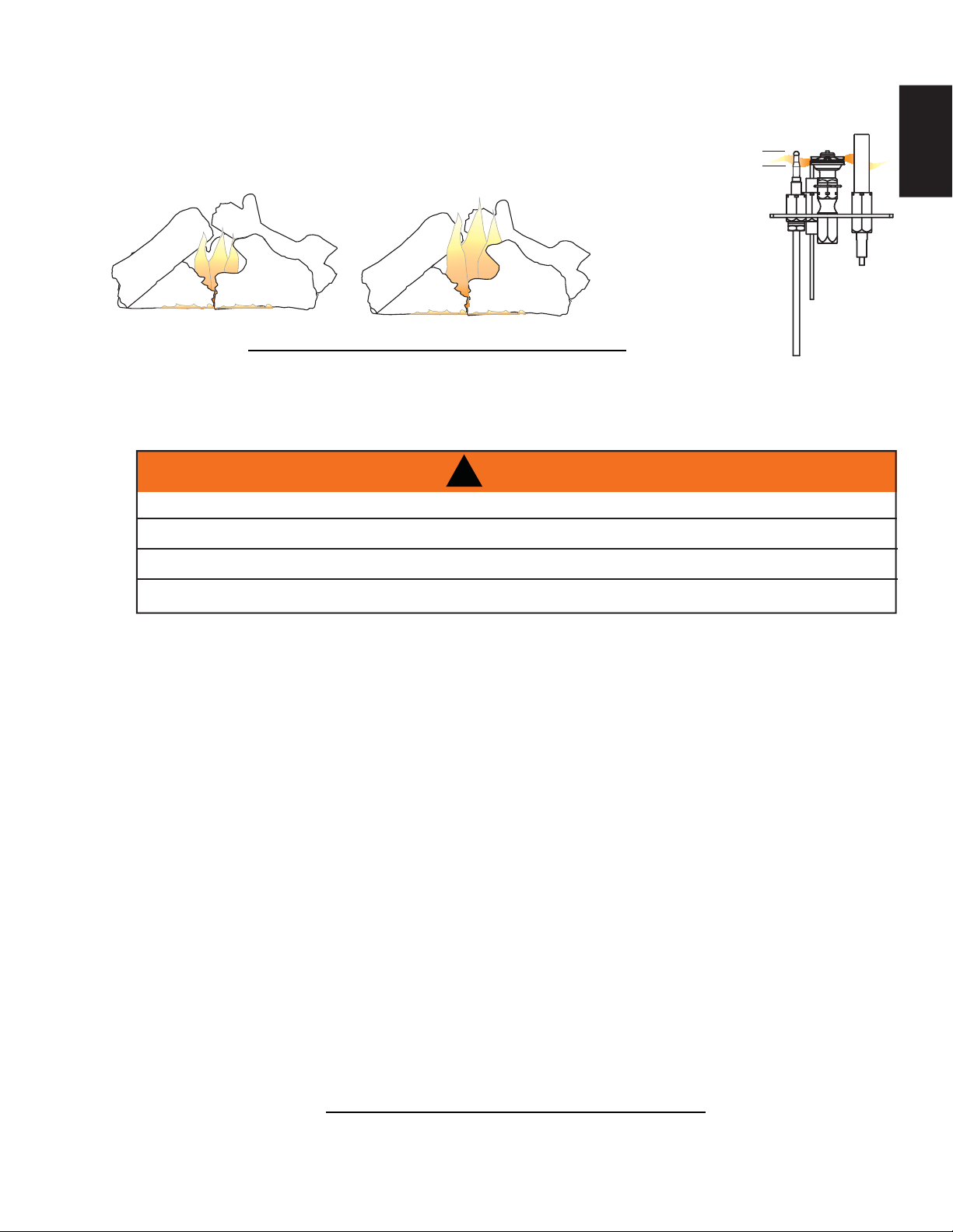
59
W415-1401 / C / 03.18.15
EN
It’s important to periodically perform a visual check of the pilot and
burner fl ames. Compare them to the illustrations provided. If any fl ame
appears abnormal call a service person.
54.2A
3/8” - 1/2”
FLAME MUST
ENVELOP UPPER
3/8" TO 1/2"
(12.7mm - 9.5mm) OF
THERMOCOUPLE &
THERMOPILE
(9.5mm - 12.7mm)
9.3 FLAME CHARACTERISTICS
10.0 MAINTENANCE
CAUTION: Label all wires prior to disconnection when servicing controls. Wiring errors can cause improper
and dangerous operation. Verify proper operation after servicing. This appliance and its venting system
should be inspected before use and at least annually by a qualifi ed service person. The appliance area must
be kept clear and free of combustible materials, gasoline or other fl ammable vapors and liquids. The fl ow of
combustion and ventilation air must not be obstructed.
A. In order to properly clean the burner and pilot assembly, remove the logs, rocks and/or glass to
expose both assemblies.
B. Keep the control compartment, media, burner, air shutter opening and the area surrounding the logs
clean by vacuuming or brushing, at least once a year.
C. Check to see that all burner ports are burning. Clean out any of the ports which may not be burning or
are not burning properly.
D. Check to see that the pilot fl ame is large enough to engulf the fl ame sensor and/or thermocouple /
thermopile as well as reaches the burner.
E. Replace the cleaned logs, rocks or glass. Failure to properly position the media may cause carboning
which can be distributed in the surrounding living area.
F. Check to see that the main burner ignites completely on all openings when turned on. A 5 to 10
second total light-up period is satisfactory. If ignition takes longer, consult your local authorized dealer /
distributor.
G. Check that the gasketing on the sides, top and bottom of the door is not broken or missing. Replace if
necessary.
H. If for any reason the vent air intake system is disassembled, re-install and re-seal per the instructions
provided for the initial installation.
I. Cleaning the safety barrier may be necessary due to excessive lint / dust from carpeting, pets, etc.
simply vacuum using the brush attachment.
J. Ensure the relief system performs effectively. Check that the gasket is not worn or damaged. Replace
if necessary.
40.1D
MAINTENANCE
MAINTENANCE
MAINTENANCE
TURN OFF THE GAS AND ELECTRICAL POWER BEFORE SERVICING THE APPLIANCE.
APPLIANCE MAY BE HOT, DO NOT SERVICE UNTIL APPLIANCE HAS COOLED.
DO NOT USE ABRASIVE CLEANERS.
DO NOT PAINT THE PILOT ASSEMBLY.
!
WARNING
MILLIVOLT
ILLUSTRATED
B36
GX36
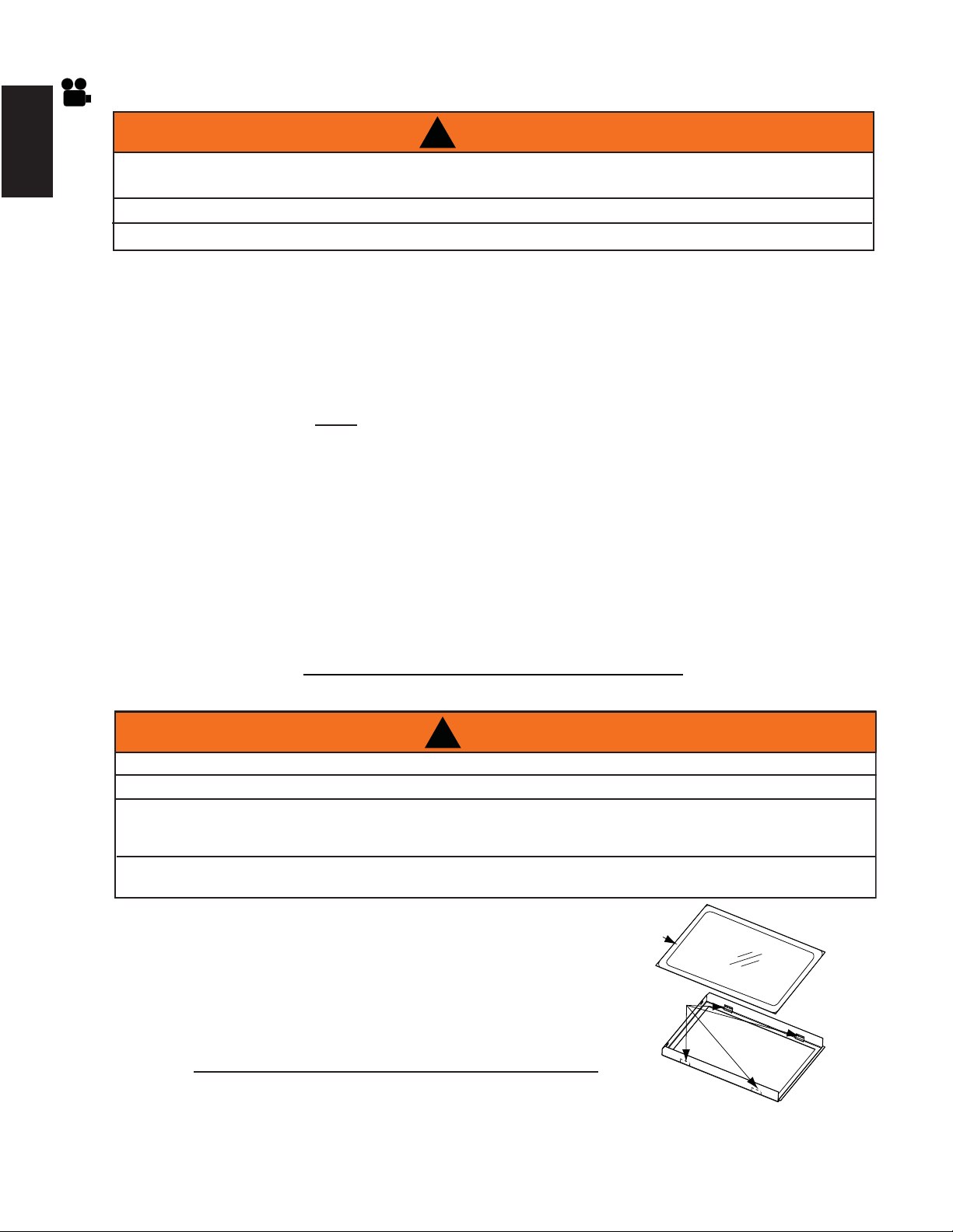
60
W415-1401 / C / 03.18.15
EN
10.1 ANNUAL MAINTENANCE
A. Place the door frame face down careful not to
scratch the paint.
B. Center the gasketed glass inside the door frame
with the thick side of the gasket facing up.
C. Bend the glass retainers located along the edge
of the door frame over the gasket holding the
glass in place. Careful not to break the glass.
!
WARNING
DO NOT USE SUBSTITUTE MATERIALS.
GLASS MAY BE HOT, DO NOT TOUCH GLASS UNTIL COOLED.
CARE MUST BE TAKEN WHEN REMOVING AND DISPOSING OF ANY BROKEN DOOR GLASS OR
DAMAGED COMPONENTS. BE SURE TO VACUUM UP ANY BROKEN GLASS FROM INSIDE THE
APPLIANCE BEFORE OPERATION.
DO NOT STRIKE, SLAM OR SCRATCH GLASS. DO NOT OPERATE APPLIANCE WITH GLASS
REMOVED, CRACKED, BROKEN OR SCRATCHED.
56.1A
GLASS
GASKET
DOOR
FRAME
GLASS
RETAINER
37.1C
!
WARNING
THE FIREBOX BECOMES VERY HOT DURING OPERATION. LET THE APPLIANCE COOL
COMPLETELY OR WEAR HEAT RESISTANT GLOVES BEFORE CONDUCTING SERVICE.
NEVER VACUUM HOT EMBERS.
DO NOT PAINT THE PILOT ASSEMBLY.
• This appliance will require maintenance which should be planned on an annual basis.
• Service should include cleaning, battery replacement, venting inspection and inspection of the burner,
media and fi rebox. Refer to the door removal section and remove the door as instructed.
• Carefully remove media if necessary (logs, glass, brick panels etc).
• Using a vacuum with a soft brush attachment, gently remove any dirt, debris or carbon build up from the
logs, fi rebox and burner. For glass media, follow the installation instructions for pre-cleaning.
• Also gently remove any build-up on the pilot assembly including, if equipped; thermopile, thermocouple,
fl ame sensor and igniter.
NOTE: The fl ame sensor may require to be cleaned using a fi ne steel wool or
Scotch-Brite™ scrubbing pad to remove any oxides.
Clean the pilot assembly using a vacuum with a
soft brush attachment.
It is important that the pilot assembly is not painted.
• Inspect all accessible gaskets and replace as required.
• Access the blower, if equipped and clean using a soft brush and vacuum.
• Re-assemble the various components in reverse order.
• Inspect the relief system. The appliance relieves through the main glass door or through the fl aps on the
fi rebox top. Ensure they open freely, and close sealed.
• Check the gas control valve pilot and Hi / Lo knobs move freely (if equipped) – replace if any stiffness in
movement is experienced.
• Check for gas leaks on all gas connections up and downstream from the gas valve including the pilot tube
connections.
10.2 DOOR GLASS REPLACEMENT
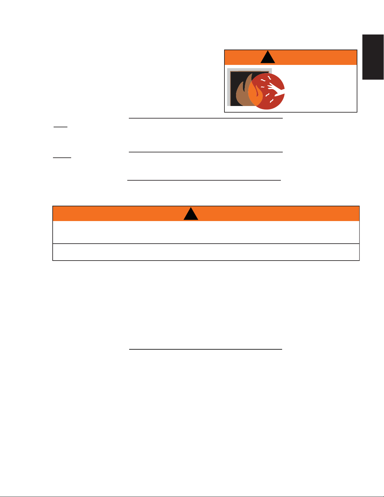
61
W415-1401 / C / 03.18.15
EN
Contact your dealer or the factory for questions concerning prices and policies on replacement parts. Normally
all parts can be ordered through your Authorized dealer / distributor.
FOR WARRANTY REPLACEMENT PARTS, A PHOTOCOPY OF THE ORIGINAL INVOICE WILL BE
REQUIRED TO HONOUR THE CLAIM.
When ordering replacement parts always give the following information:
• Model & Serial Number of appliance
• Installation date of appliance
• Part number
• Description of part
• Finish
* IDENTIFIES ITEMS WHICH ARE NOT ILLUSTRATED. FOR FURTHER INFORMATION, CONTACT YOUR
AUTHORIZED DEALER.
41.2
FAILURE TO POSITION THE PARTS IN ACCORDANCE WITH THIS MANUAL OR FAILURE TO USE
ONLY PARTS SPECIFICALLY APPROVED WITH THIS APPLIANCE MAY RESULT IN PROPERTY
DAMAGE OR PERSONAL INJURY.
** THIS IS A FAST ACTING THERMOCOUPLE. IT IS AN INTEGRAL SAFETY COMPONENT. REPLACE ONLY WITH
A FAST ACTING THERMOCOUPLE SUPPLIED BY WOLF STEEL LTD.
!
WARNING
10.3 CARE OF GLASS
5.1
DO NOT CLEAN GLASS WHEN HOT! DO NOT USE
ABRASIVE CLEANERS TO CLEAN GLASS.
Buff lightly with a clean dry soft cloth. Clean both sides
of the glass after the fi rst 10 hours of operation with a
recommended fi replace glass cleaner. Thereafter clean
as required. If the glass is not kept clean permanent
discoloration and / or blemishes may result.
HOT GLASS WILL
CAUSE BURNS.
DO NOT TOUCH GLASS
UNTIL COOLED.
NEVER ALLOW CHILDREN
TO TOUCH GLASS.
!
WARNING
5.5
This appliance is factory equipped with 4mm tempered glass. Use only replacement glass available from your
Napoleon® dealer. DO NOT SUBSTITUTE MATERIALS.
5.5.1
This appliance is factory equipped with 5mm ceramic glass. Use only replacement glass available from your
Napoleon® dealer. DO NOT SUBSTITUTE MATERIALS.
B36:
GX36:
11.0 REPLACEMENTS
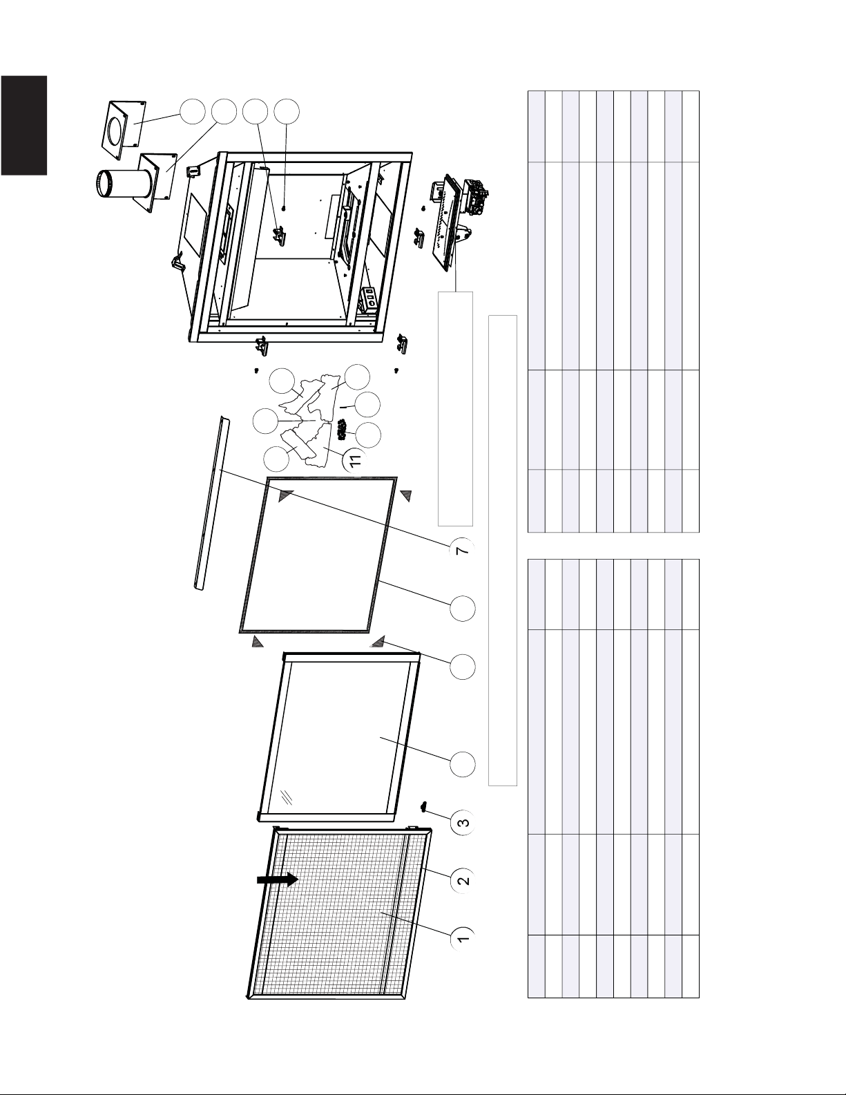
62
W415-1401 / C / 03.18.15
EN
GL-696
SAFETY BARRIER
ASSEMBLY
B36 OVERVIEW
FOR REPLACEMENTS PARTS REFER
TO: "VALVE TRAIN ASSEMBLY"
REF. NO. PART NUMBER DESCRIPTION
3
4
5
6
7
8
9
REF. NO. PART NUMBER DESCRIPTION
ITEMS MAY NOT APPEAR EXACTLY AS ILLUSTRATED
W565-0144 SAFETY SCREEN
W010-3402 DOOR ASSEMBLY
W335-0063 HOOD
LEFT CROSSOVER LOG (GL-696)
REAR LOG (GL-696)
W135-0546
W135-0588
03.16.15 / A
2
1
STOCKED STOCKED
YES
YES
YES
YES
LOG LOCATING PIN
W485-0042
W385-0334 NAPOLEON LOGO
10
18
14
15
16
17
13
YES
YES
W570-0135 SHOULDER SCREWS (X4)
YES
W010-3070 DOOR LATCHES (X4)
W290-0259 GASKET FLUE PIPE ASSY
W010-3279 4" EXHAUST FLUE PIPE ASSY
YES
GLOWING EMBERS (GL-696)
W361-0016
W562-0009 DOOR GASKET
W667-0018 GASKET TAPE (X4)
YES
YES
YESRIGHT SIDE LOG (GL-696)
W135-0545
YESLEFT SIDE LOG (GL-696)W135-0544
12
W010-3072 SAFETY BARRIER ASSEMBLY
11
RIGHT CROSSOVER LOG (GL-696)W135-0589
YES
YES
201 202 203 204 205 206
207
8
9
1010
11
13
14
12
15
16
17
18
12.0 B36 OVERVIEW
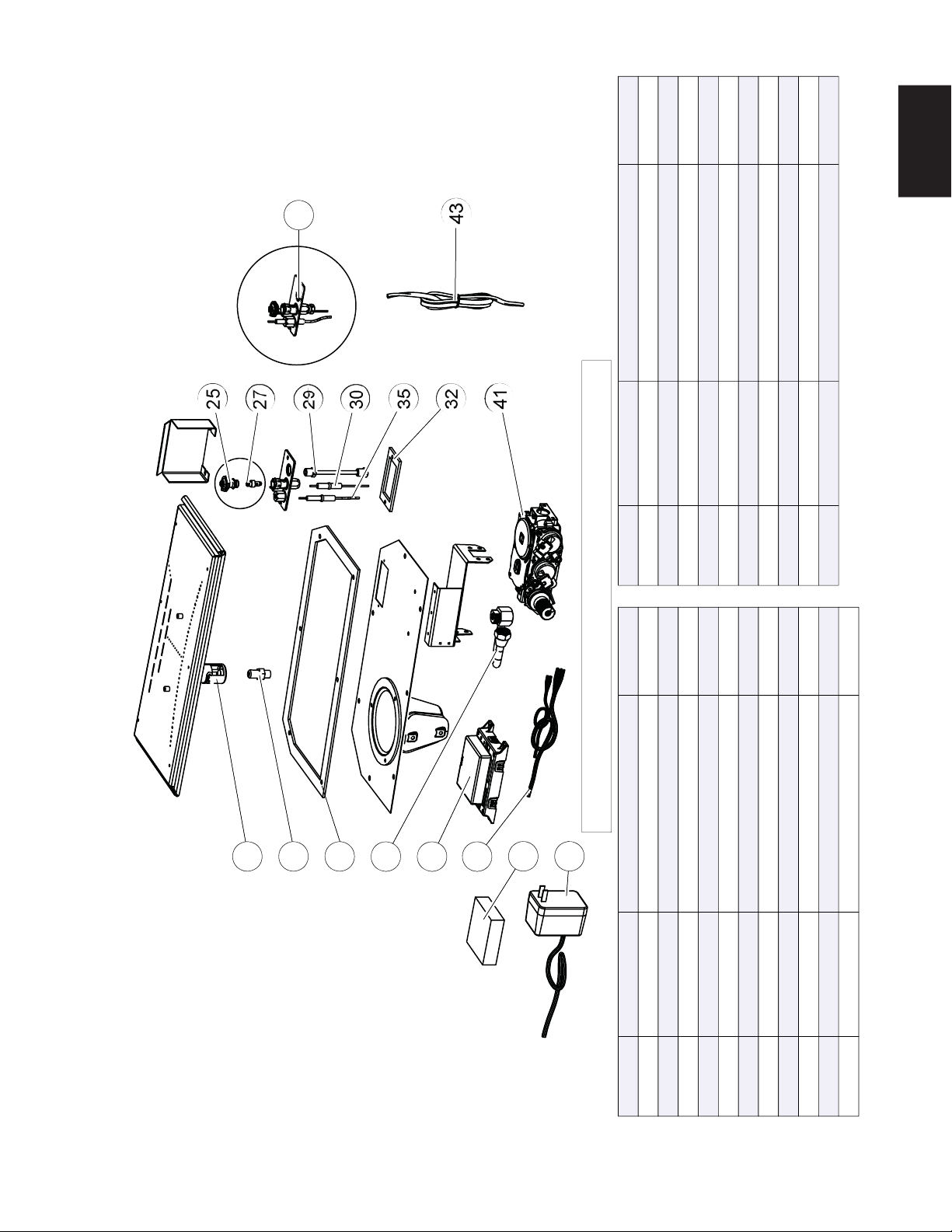
63
W415-1401 / C / 03.18.15
EN
ITEMS MAY NOT APPEAR EXACTLY AS ILLUSTRATED
REF. NO. PART NUMBER DESCRIPTION STOCKED
19 W100-0190 BURNER ASSEMBLY YES
20 W456-0047 BURNER ORIFICE #47 (NG) YES
20 W456-0056 BURNER ORIFICE #56 (LP) YES
21 W290-0248 VALVE TRAIN GASKET YES
25 W335-0039 PILOT HOOD YES
27 W455-0070 PILOT ORIFICE #62 (NG) YES
27 W455-0068 PILOT ORIFICE #35 (LP) YES
29 W720-0062 PILOT TUBE (w/ FITTINGS) YES
30 W240-0013 ELECTRODE (w/ WIRE) YES
32 W290-0029 PILOT GASKET
35 W245-0025 THERMOSENSOR YES
REF. NO. PART NUMBER DESCRIPTION STOCKED
36 W432-0046 MANIFOLD FLEX PIPE YES
37 W190-0072 CONTROL MODULE YES
38 W010-1986 WIRE HARNESS YES
39 W350-0702 BATTERY BACK-UP YES
40 W707-0010 TRANSFORMER YES
41 W725-0062 886 PROFLAME VALVE (NG) YES
41 W725-0063 886 PROFLAME VALVE (LP) YES
42 W010-2763 PILOT ASSEMBLY (NG)
42 W010-2808 PILOT ASSEMBLY (LP)
43 W750-0270 WIRE SWITCH YES
03.16.15 / B
43
36
31
30
28
26
37
23
21
20
42
40
38
33
39
44
41
42
35
30
29
27
25
36
21
20
19
41
39
37
32
38
43
40
13.0 B36 ELECTRONIC VALVE TRAIN ASSEMBLY
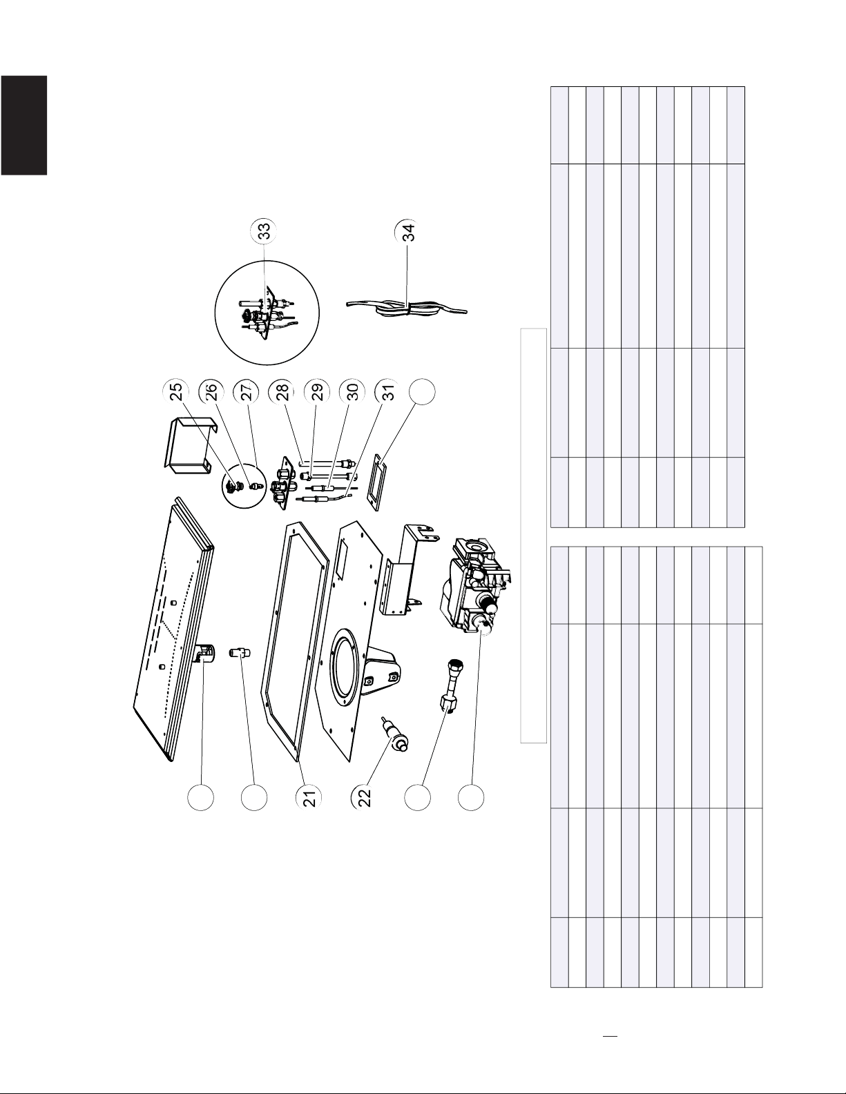
64
W415-1401 / C / 03.18.15
EN
03.16.15 / B
ITEMS MAY NOT APPEAR EXACTLY AS ILLUSTRATED
REF. NO. PART NUMBER DESCRIPTION STOCKED
19 W100-0190 BURNER ASSEMBLY YES
20 W456-0047 BURNER ORIFICE #47 (NG) YES
20 W456-0056 BURNER ORIFICE #56 (LP) YES
21 YES
22
W290-0248 VALVE TRAIN GASKET
YES
23 W432-0078 MANIFOLD FLEX PIPE YES
24 W725-0025 VALVE (NG) YES
24 W725-0043 VALVE (LP) YES
25 W335-0039 PILOT HOOD YES
26 W455-0070 PILOT ORIFICE #62 (NG) YES
26 W455-0068 PILOT ORIFICE #35 (LP) YES
REF. NO. PART NUMBER DESCRIPTION STOCKED
27 W010-0801 PILOT (NG) YES
27 W010-0800 PILOT (LP) YES
28 W680-0004 THERMOPILE YES
29 W720-0062 PILOT TUBE (w/ FITTINGS) YES
30 W240-0006 ELECTRODE (w/ WIRE) YES
31 W680-0005 THERMOCOUPLE YES
32 W290-0029 PILOT GASKET
33 W010-0798 PILOY ASSEMBLY (NG)
33 W010-0799 PILOT ASSEMBLY (LP)
34 W750-0112 WIRE SWITCH
34
28
32
31
30
29
27
26
24
23
21
20
22
25
33
35
33
27
31
30
29
28
26
25
23
22
20
19
21
24
32
34
W357-0001 PUSH BUTTON IGNITOR
14.0 B36 MILLIVOLT VALVE TRAIN ASSEMBLY
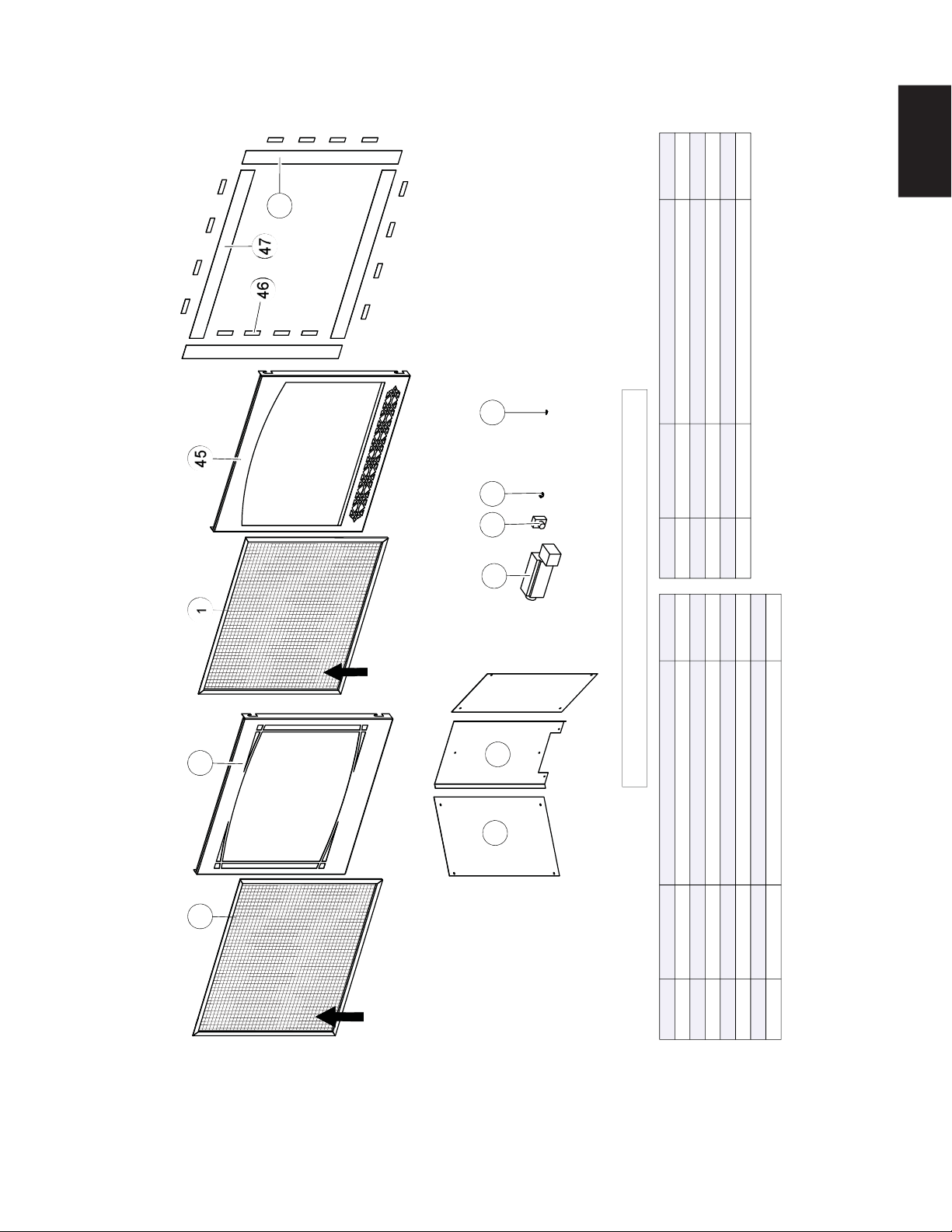
65
W415-1401 / C / 03.18.15
EN
54
1
47
145
53
52
46
48
49
55
50
51
53
1
46
144
52
51
45
47
48
54
49
50
ITEMS MAY NOT APPEAR EXACTLY AS ILLUSTRATED
TK35
PRPB36 AUB
H35FZ35F
SAFETY
SCREEN
SAFETY
SCREEN
REF. NO. PART NUMBER DESCRIPTION STOCKED
1 W565-0144 SAFETY SCREEN (Z35F & H35F) YES
44 W010-3281 ZEN FRONT ASSEMBLY (Z35F)
45 W010-3282 HERRITAGE FRONT ASSEMBLY(H35F)
46 W430-0003 MAGNET (X16) (TK35) YES
47 W715-0953 TOP/BOTTOM TRIM (X2) (TK35)
48 W715-0952 SIDE TRIM (X2) (TK35)
49 W475-1012 SIDE PORCELAIN PANEL(X2) (PRPB36)
REF. NO. PART NUMBER DESCRIPTION STOCKED
50 W475-1012 REAR PORCELAIN PANEL (PRPB36)
51 W062-0051 BLOWER (AUB) YES
52 KB-35 VARIABLE SPEED SWITCH YES
53 W690-0002 THERMODISC YES
54 ACS-SIT ANTI-CONDENSATION SWITCH (ACS) YES
03.16.15 / A
B36 ACCESSORIES
15.0 B36 ACCESSORIES
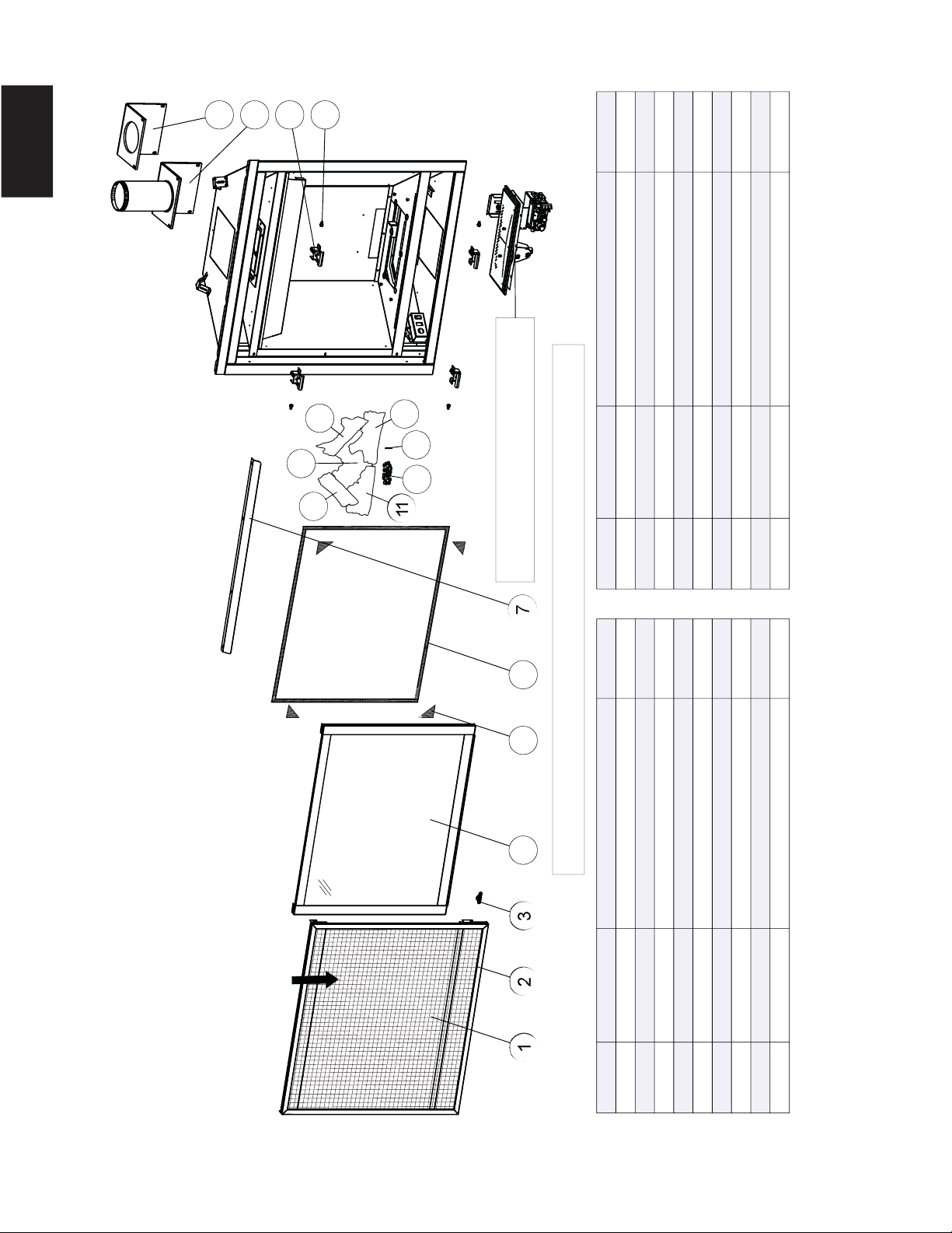
66
W415-1401 / C / 03.18.15
EN
GL-696
SAFETY BARRIER
ASSEMBLY
GX36 OVERVIEW
FOR REPLACEMENTS PARTS REFER
TO: "VALVE TRAIN ASSEMBLY"
REF. NO. PART NUMBER DESCRIPTION
3
4
5
6
7
8
9
REF. NO. PART NUMBER DESCRIPTION
ITEMS MAY NOT APPEAR EXACTLY AS ILLUSTRATED
W565-0144 SAFETY SCREEN
W010-3402 DOOR ASSEMBLY
W335-0063 HOOD
LEFT CROSSOVER LOG (GL-696)
REAR LOG (GL-696)
W135-0546
W135-0588
03.16.15 / A
2
1
STOCKED STOCKED
YES
YES
YES
YES
LOG LOCATING PIN
W485-0042
W385-0334 NAPOLEON LOGO
10
18
14
15
16
17
13
YES
YES
W570-0135 SHOULDER SCREWS (X4)
YES
W010-3070 DOOR LATCHES (X4)
W290-0259 GASKET FLUE PIPE ASSY
W010-3279 4" EXHAUST FLUE PIPE ASSY
YES
GLOWING EMBERS (GL-696)
W361-0016
W562-0009 DOOR GASKET
W667-0018 GASKET TAPE (X4)
YES
YES
YESRIGHT SIDE LOG (GL-696)
W135-0545
YESLEFT SIDE LOG (GL-696)W135-0544
12
W010-3072 SAFETY BARRIER ASSEMBLY
11
RIGHT CROSSOVER LOG (GL-696)W135-0589
YES
YES
201 202 203 204 205 206
207
8
9
1010
11
13
14
12
15
16
17
18
16.0 GX36 OVERVIEW
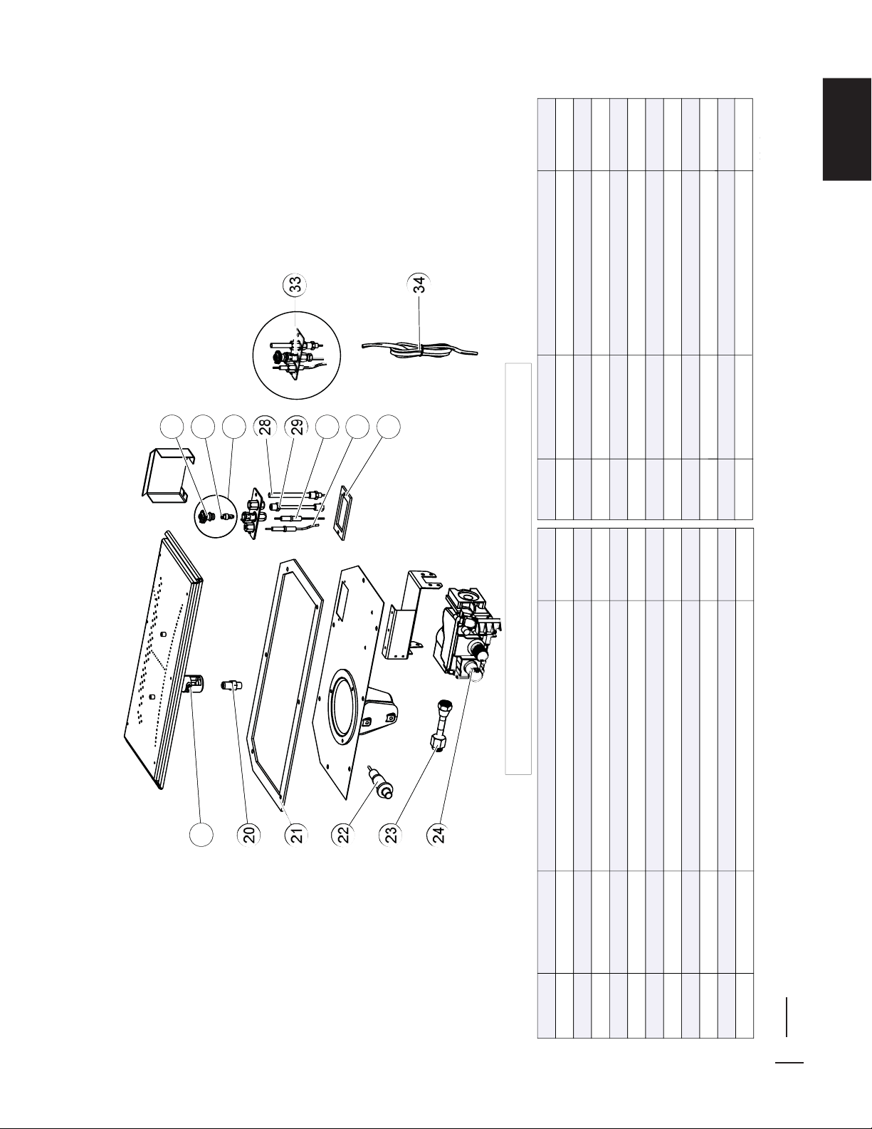
67
W415-1401 / C / 03.18.15
EN
03.16.15 / B
ITEMS MAY NOT APPEAR EXACTLY AS ILLUSTRATED
REF. NO. PART NUMBER DESCRIPTION STOCKED
19 W100-0191 BURNER ASSEMBLY
20
YES
REF. NO. PART NUMBER STOCKED
GX36
MILLIVOLT
VALVE
TRAIN
ASSEMBLY
33
27
31
30
29
28
26
23
25
21
19
20
24
32
22
34
33
27
31
30
29
28
26
23
25
21
19
20
24
32
22
34
YES
27
27
28
29
30
31
32
33
33
34
W010-0801
W010-0800
W680-0004
W720-0062
W240-0006
W680-0005
W290-0029
W010-0798
W010-0799
W750-0112
DESCRIPTION
PILOT (NG) YES
PILOT (LP) YES
THERMOPILE YES
PILOT TUBE (w/ FITTINGS) YES
ELECTRODE (w/ WIRE) YES
THERMOCOUPLE YES
PILOT GASKET
PILOY ASSEMBLY (NG)
PILOT ASSEMBLY (LP)
WIRE SWITCH
26 W455-0068 PILOT ORIFICE #35 (LP) YES
21 W290-0248
22 W357-0001
23 W432-0078
24 W725-0025
24 W725-0043
25 W335-0039
26 W455-0070
VALVE TRAIN GASKET YES
PUSH BUTTON IGNITOR YES
MANIFOLD FLEX PIPE YES
VALVE (NG) YES
VALVE (LP) YES
PILOT HOOD YES
PILOT ORIFICE #62 (NG) YES
20 W456-0053 BURNER ORIFICE #53 (LP) YES
20
W456-0042 TOP VENT BURNER ORIFICE #42 (NG)
YES
W456-0043 REAR VENT BURNER ORIFICE #43 (NG)
17.0 GX36 MILLIVOLT VALVE TRAIN ASSEMBLY
NOTE: A #42 orifi ce was supplied with your appliance. In installations with a vertical rise greater than
8" (203mm) in the vent confi guration, the #42 orifi ce must be used to increase the fl ame size.
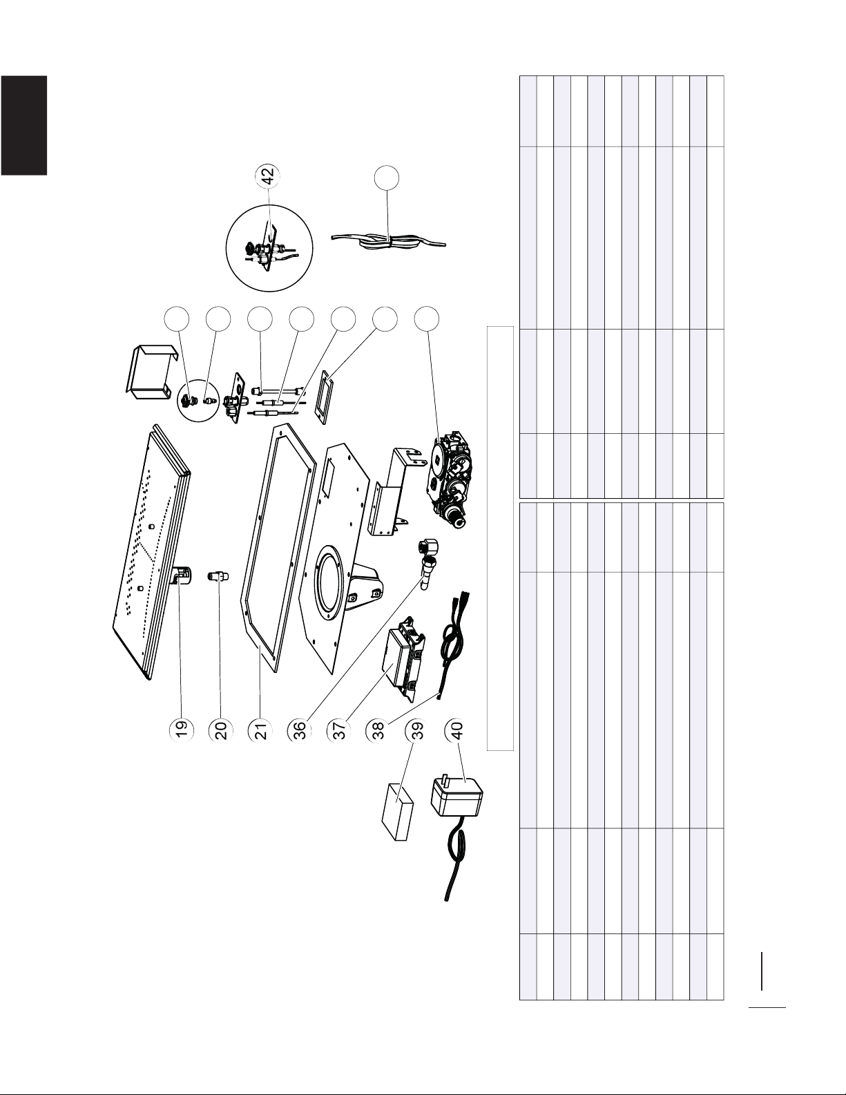
68
W415-1401 / C / 03.18.15
EN
03.16.15 / B
GX36 ELECTRONIC VALVE TRAIN ASSEMBLY
ITEMS MAY NOT APPEAR EXACTLY AS ILLUSTRATED
REF. NO. PART NUMBER STOCKED
19 W100-0191 BURNER ASSEMBLY YES
REF. NO. PART NUMBER STOCKED
42
35
30
29
26
25
36
21
19
20
41
39
37
38
32
43
40
42
35
30
29
26
25
36
21
19
20
41
39
37
38
32
43
40
36
37
38
39
40
41
41
42
42
43
W432-0046
W190-0072
W010-1986
W350-0702
W707-0010
W725-0062
W725-0063
W010-2763
W010-2808
W750-0270
DESCRIPTION
MANIFOLD FLEX PIPE
CONTROL MODULE
WIRE HARNESS
BATTERY BACK-UP
TRANSFORMER
886 PROFLAME VALVE (NG)
886 PROFLAME VALVE (LP)
PILOT ASSEMBLY (NG)
PILOT ASSEMBLY (LP)
WIRE SWITCH
YES
YES
YES
YES
YES
YES
YES
YES
35 W245-0025 THERMOSENSOR YES
20
21
25
26
26
29
30
32
W456-0053
W290-0248
W335-0039
W455-0070
W455-0068
W720-0062
W240-0013
W290-0029
PILOT ORIFICE #62 (NG)
DESCRIPTION
BURNER ORIFICE #53 (LP) YES
VALVE TRAIN GASKET YES
PILOT HOOD YES
YES
PILOT ORIFICE #35 (LP) YES
PILOT TUBE (w/ FITTINGS) YES
ELECTRODE (w/ WIRE) YES
PILOT GASKET
20 W456-0043 REAR VENT BURNER ORIFICE #43 (NG) YES
20 W456-0042 TOP VENT BURNER ORIFICE #42 (NG) YES
18.0 GX36 ELECTRONIC VALVE TRAIN ASSEMBLY
NOTE: A #42 orifi ce was supplied with your appliance. In installations with a vertical rise greater than
8" (203mm) in the vent confi guration, the #42 orifi ce must be used to increase the fl ame size.
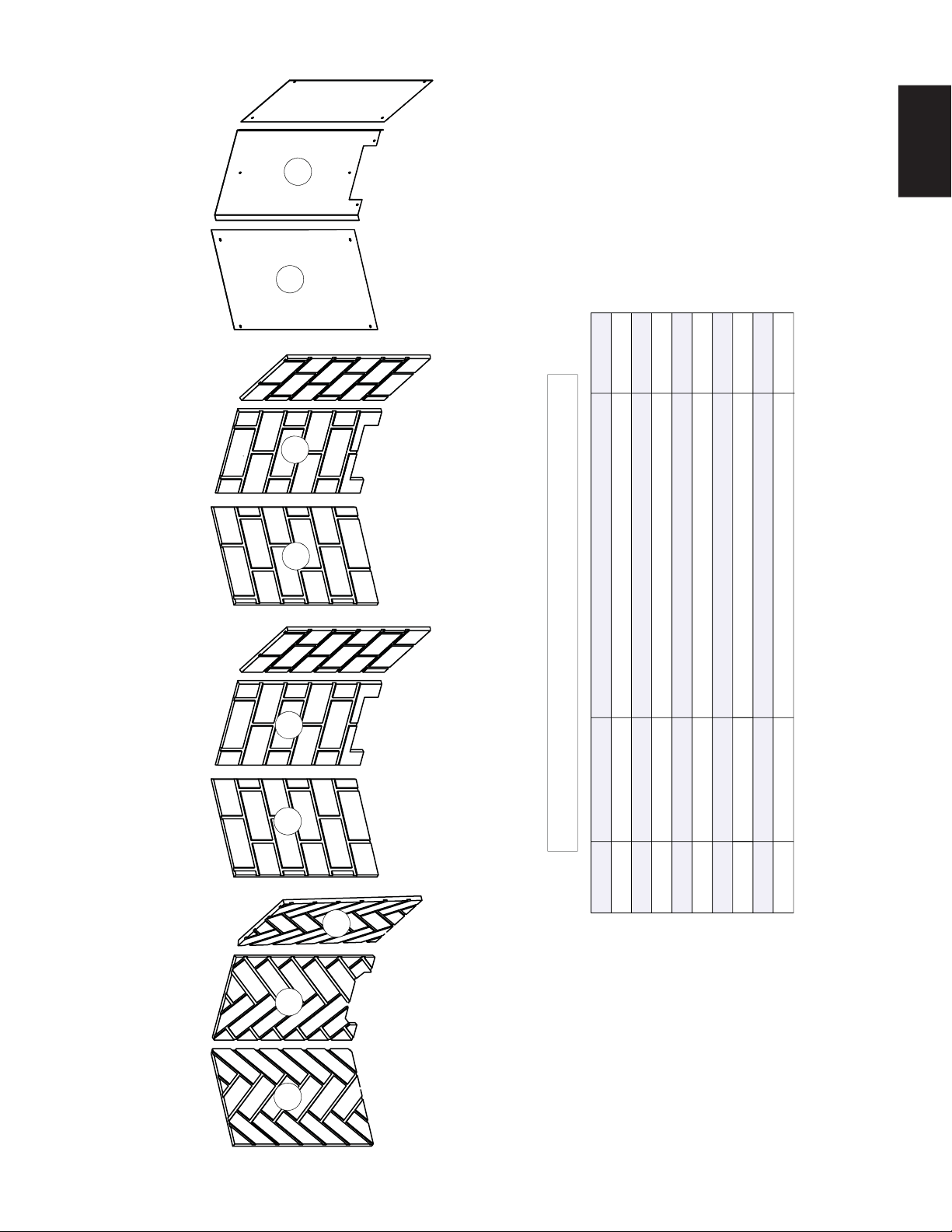
69
W415-1401 / C / 03.18.15
EN
GD861KT
PRPB36
GD863KTGD862KT
44
45
46
47
48
49
50
51
52
03.16.15 / A
ITEMS MAY NOT APPEAR EXACTLY AS ILLUSTRATED
REF. NO. PART NUMBER DESCRIPTION
45
46
47
48
44
STOCKED
52
49
50
51
LEFT SIDE HERRINGBONE PANEL (GD861KT)
REAR HERRINGBONE PANEL (GD861KT)
W475-0994
W475-0993
SIDE SANDSTONE BRICK PANEL (X2) (GD862KT)
REAR SANDSTONE BRICK PANEL (GD862KT)
W475-0992
W475-0991
RIGHT SIDE HERRINGBONE PANEL (GD861KT)W475-0995
SIDE PORCELAIN PANELS (X2) (PRPB36)
REAR PORCELAIN PANEL (PRPB36)
W475-0989
W475-0990
SIDE NEWPORT BRICK PANEL (X2) (GD863KT)
REAR NEWPORT BRICK PANEL (GD863KT)
W475-0997
W475-0996
(g)
19.0 GX36 ACCESSORIES
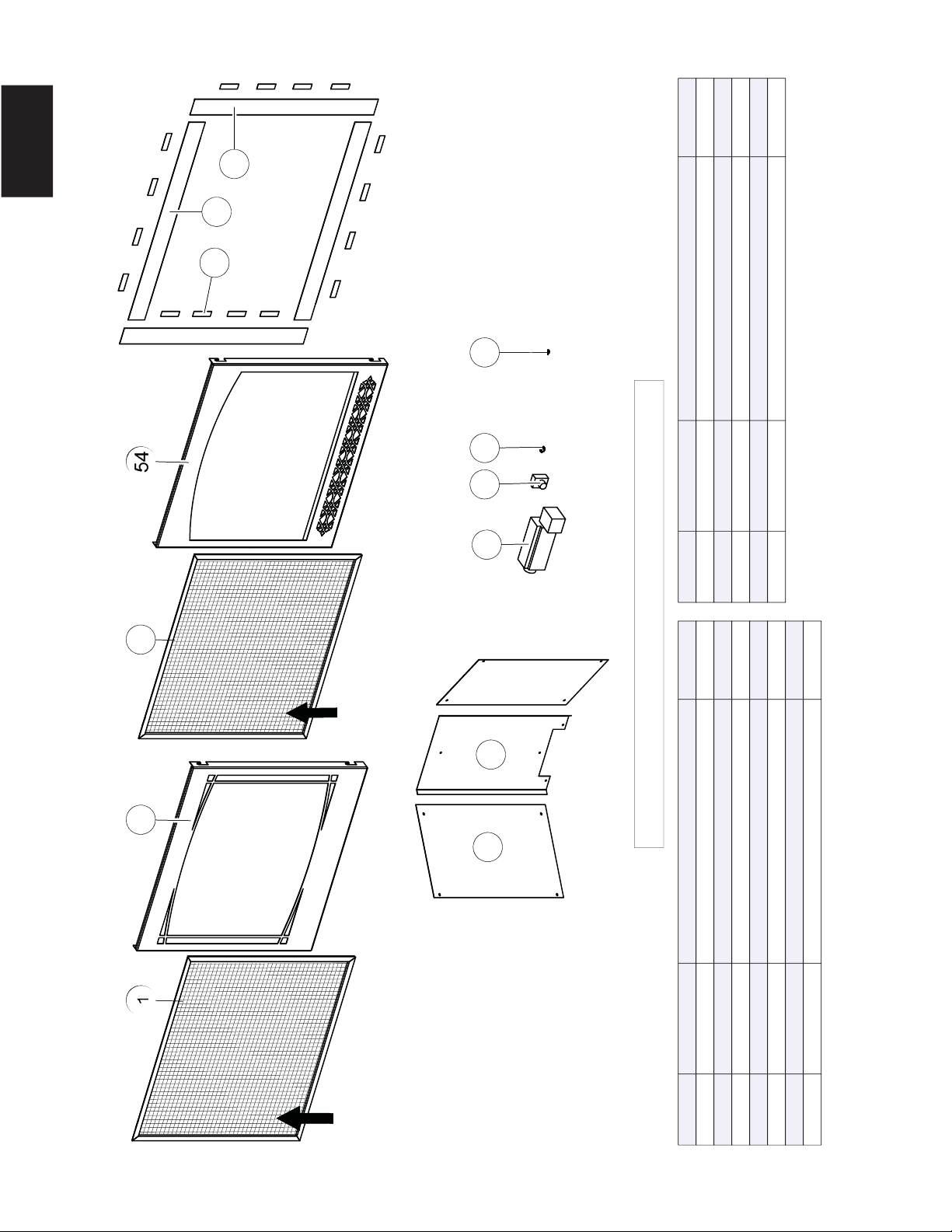
70
W415-1401 / C / 03.18.15
EN
54
1
47
145
53
52
46
48
49
55
50
51
62
1
55
153
61
60
54
56
57
63
58
59
ITEMS MAY NOT APPEAR EXACTLY AS ILLUSTRATED
TK35
PRPB36 AUB
H35FZ35F
SAFETY
SCREEN
SAFETY
SCREEN
REF. NO. PART NUMBER DESCRIPTION STOCKED
1 W565-0144 SAFETY SCREEN (Z35F & H35F) YES
53 W010-3281 ZEN FRONT ASSEMBLY (Z35F)
54 W010-3282 HERRITAGE FRONT ASSEMBLY(H35F)
55 W430-0003 MAGNET (X16) (TK35) YES
56 W715-0953 TOP/BOTTOM TRIM (X2) (TK35)
57 W715-0952 SIDE TRIM (X2) (TK35)
58 W475-1012 SIDE PORCELAIN PANEL(X2) (PRPB36)
REF. NO. PART NUMBER DESCRIPTION STOCKED
59 W475-1012 REAR PORCELAIN PANEL (PRPB36)
60 W062-0051 BLOWER (AUB) YES
61 KB-35 VARIABLE SPEED SWITCH YES
62 W690-0002 THERMODISC YES
63 ACS-SIT
A
NTI-CONDENSATION SWITCH (ACS) YES
03.16.15 / B
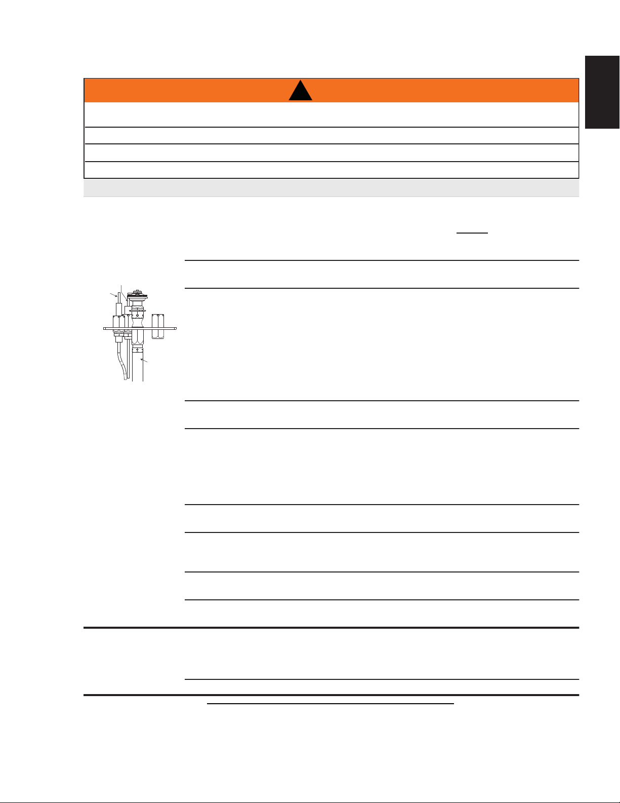
71
W415-1401 / C / 03.18.15
EN
20.0 TROUBLESHOOTING (ELECTRONIC)
SYMPTOM PROBLEM TEST SOLUTION
Pilot will not light.
Makes noise with
no spark at pilot
burner.
Wiring. - Verify the wire for the sensor and the wire for the
ignitor are connected to the correct terminals (not
reversed) on the module. NOTE: Sensor has 3/16”
(4.8mm) connection and ignitor has 1/8” (3.2mm)
connection.
Loose connection. - Verify no loose connections, electrical shorts in the
wiring or ground out to any metal object.
Module. - Turn the ON/OFF switch to the “OFF” position.
Remove the igniter wire from the module. Place
the ON/OFF switch to the “ON” position. Hold a
grounded wire about 3/16” (4.8mm) away from the
ignitor (spark) terminal on the module. If no spark
the ignitor terminal module must be replaced. If
there is a spark the ignitor terminal is fi ne. Inspect
pilot assembly for a shorted wire or cracked
insulator around the electrode.
Igniter Spark gap is
incorrect.
- Spark gap of the ignitor to the pilot should be 1/8”
(3.2mm).
Transformer. - Verify the transformer is installed and plugged into
the module. Check voltage of the transformer under
load at the spade connections on the module with
the ON/OFF switch in the “ON” position. Acceptable
readings of a good transformer are between 6.2 and
7.0 volts A.C.
Battery backup (if power
is off)
- Check batteries.
A shorted or loose
Connection.
- Remove and reinstall the wiring harness that plugs
into the module. Remove and verify continuity of
each wire in wiring harness.
Improper switch wiring. - Troubleshoot the system with the simplest ON/OFF
switch.
Module is not grounded. - Verify the valve and pilot assemblies are properly
grounded to the metal chassis of the appliance or log set.
Pilot sparks but
will not light.
Gas supply. - Verify that the incoming gas line ball valve is “Open”.
Verify that the inlet pressure reading is within
acceptable limits, inlet pressures must not exceed
14” W.C. (34.9mb).
Out of propane gas. - Fill the tank.
SENSOR
IGNITOR
(SPARK)
PILOT TUBE
42.7A
!
WARNING
ALWAYS LIGHT THE PILOT WHETHER FOR THE FIRST TIME OR IF THE GAS SUPPLY HAS RUN OUT,
WITH THE GLASS DOOR OPEN OR REMOVED.
TURN OFF THE GAS AND ELECTRICAL POWER BEFORE SERVICING THE APPLIANCE.
APPLIANCE MAY BE HOT, DO NOT SERVICE UNTIL APPLIANCE HAS COOLED.
DO NOT USE ABRASIVE CLEANERS.

72
W415-1401 / C / 03.18.15
EN
SYMPTOM PROBLEM TEST SOLUTION
Carbon is being
deposited on
glass, logs,
rocks, media
or combustion
chamber surfaces.
Air shutter has become
blocked.
- Ensure air shutter opening is free of lint or other
obstructions.
Flame is impinging on the
glass, logs, rocks, media
or combustion chamber.
- Check that the glass, logs, rocks or media are
correctly positioned.
- Open air shutter to increase the primary air.
- Check the input rate: check the manifold pressure
and orifi ce size as specifi ed by the rating plate
values.
- Check that the door gasketing is not broken or
missing and that the seal is tight.
- Check that both vent liners are free of holes and
well sealed at all joints.
- Check that minimum rise per foot has been adhered
to for any horizontal venting.
Continues to
spark and pilot
lights, but main
burner will not
light.
Short or loose
connection in sensor rod.
- Verify all connections. Verify the connections
from the pilot assembly are tight; also verify these
connections are not grounding out to any metal.
Poor fl ame rectifi cation
or contaminated
sensor rod.
- Verify the fl ame is engulfi ng the sensor rod. This
will increase the fl ame rectifi cation. Verify correct
pilot orifi ce is installed and inlet gas specifi cations
to manual. (Remember, the fl ame carries the
rectifi cation current, not the gas. If the fl ame lifts
from pilot hood, the circuit is broken. A wrong orifi ce
or to high of an inlet pressure can cause the pilot
fl ame to lift.) The sensor rod may need cleaning.
Poor grounding between
pilot assembly and
gas valve.
- Verify that the wire harness is fi rmly connected to
module. Verify that the ceramic insulator around the
sensor rod is not cracked, damaged, or loose. Verify
the connection from the sensor rod to the sensor wire.
Damaged pilot or dirty
sensor rod.
- Clean sensor rod with a fi ne steel wool to remove
any contamination that may have accumulated on
the sensor rod. Verify continuity with multimeter with
ohms set at the lowest range.
Pilot lights
Stops sparking
/ pilot remains lit
but burner will
not turn on.
Wiring / Connection. - Inspect all wires, ensure good tight connections.
Verify that all wiring is installed exactly as specifi ed.
Wiring harness. - Inspect the wiring harness, and verify the harness
is tightly connected to the module. Verify that all
wires are connected in the right order. See “WIRING
DIAGRAM” section.
Exhaust fumes
smelled in room,
headaches.
Appliance is spilling. - Check all seals.
- Check if exhaust is re-entering through an open
door or window.
42.7_2

73
W415-1401 / C / 03.18.15
EN
42.7_3B
SYMPTOM PROBLEM TEST SOLUTION
White / grey fi lm
forms.
Sulphur from fuel is being
deposited on glass, logs or
combustion chamber
surfaces.
- Clean the glass, see “CARE OF GLASS” section
- DO NOT CLEAN GLASS WHEN HOT.
- If deposits are not cleaned off regularly, the glass
may become permanently marked.
Flames are very
aggressive.
Door is ajar. - Tighten door clamps if applicable.
Venting action is too great. - Restrict vent exit with restrictor plate. See
“RESTRICTING VENTS” section if applicable.
Main burner fl ame
is a blue, lazy,
transparent
fl ame.
Blockage in vent. - Remove blockage. In extreme conditions, ice
buildup may occur on the terminal and should be
removed. To minimize this from happening again,
it is recommended that the vent lengths that pass
through unheated spaces (attics, garages, crawl
spaces) be wrapped with an insulated mylar sleeve.
Prevent sleeve from sagging. Contact your local
authorized dealer for more information.
Compromised venting. - Check venting system parameters (seal, length,
rise, etc.).
Main burner goes
out: pilot goes out.
Vent recirculation. - Check joint seals and installation.

74
W415-1401 / C / 03.18.15
EN
21.0 TROUBLESHOOTING (MILLIVOLT)
SYMPTOM PROBLEM TEST SOLUTION
Main burner goes out; pilot
stays on.
Pilot fl ame is not large
enough or not engulfi ng the
thermopile.
- Turn up the pilot fl ame.
- Replace pilot assembly.
Thermopile shorting. - Clean thermopile connection to the valve. Reconnect.
- Replace thermopile / valve.
Remote wall switch wire is too
long; too much resistance in
the system.
- Shorten wire to correct length or wire gauge.
Faulty thermostat or switch. - Replace.
Main burner goes out; pilot
goes out.
Refer to “MAIN BURNER GOES OUT; PILOT STAYS ON”
Vent is blocked - Check for vent blockage.
Vent is re-circulating - Check joint seals and installation
Flexible vent has become
disconnected from appliance.
- Re-attach to appliance.
- Cap was not replaced.
Pilot goes out when the
gas knob is released.
The gas valve has an
interlock device which
will not allow the pilot
burner to be lit until
the thermocouple
has cooled. Allow
approximately 60
seconds for the
thermocouple to cool.
System is not correctly purged - Purge the gas line.
Out of propane gas. - Fill the tank.
Pilot fl ame is not large
enough.
- Turn up the pilot fl ame.
Pilot fl ame is not engulfi ng the
thermocouple
- Gently twist the pilot head to improve the fl ame pattern
around the thermocouple.
Thermocouple shorting / faulty. - Loosen and tighten thermocouple.
- Clean thermocouple and valve connection.
- Replace thermocouple.
- Replace valve.
Faulty valve. - Replace.
Pilot burning; no gas to
main burner; gas knob
is on ‘HI’; wall switch /
thermostat is on.
Thermostat or switch is
defective
- Connect a jumper wire across the wall switch terminals;
if main burner lights, replace switch / thermostat.
Wall switch wiring is defective. - Disconnect the switch wires & connect a jumper wire
across terminals 1 & 3; if the main burner lights, check
the wires for defects and/or replace wires.
Main burner orifi ce is plugged. - Remove stoppage in orifi ce.
Faulty valve. - Replace.
Pilot goes out while
standing; Main burner is in
‘OFF’ position.
Gas piping is undersized. - Turn on all gas appliances and see if pilot fl ame
fl utters,
diminishes or extinguishes, especially when main burner
ignites. Monitor appliance supply working pressure.
- Check if supply piping size is to code. Correct all
undersized piping.
Main burner fl ame is a
blue, lazy, transparent
fl ame.
Blockage in vent. - Remove blockage. In really cold conditions, ice buildup
may occur on the terminal and should be removed as
required. To minimize this from happening again, it is
recommended that the vent lengths that pass through
unheated spaces (attics, garages, crawl spaces) be
wrapped with an insulated mylar sleeve. Prevent sleeve
from sagging. Contact your local authorized dealer for
more information.
42.3B
!
WARNING
ALWAYS LIGHT THE PILOT WHETHER FOR THE FIRST TIME OR IF THE GAS SUPPLY HAS RUN OUT,
WITH THE GLASS DOOR OPEN OR REMOVED.
TURN OFF THE GAS AND ELECTRICAL POWER BEFORE SERVICING THE APPLIANCE.
APPLIANCE MAY BE HOT, DO NOT SERVICE UNTIL APPLIANCE HAS COOLED.
DO NOT USE ABRASIVE CLEANERS.
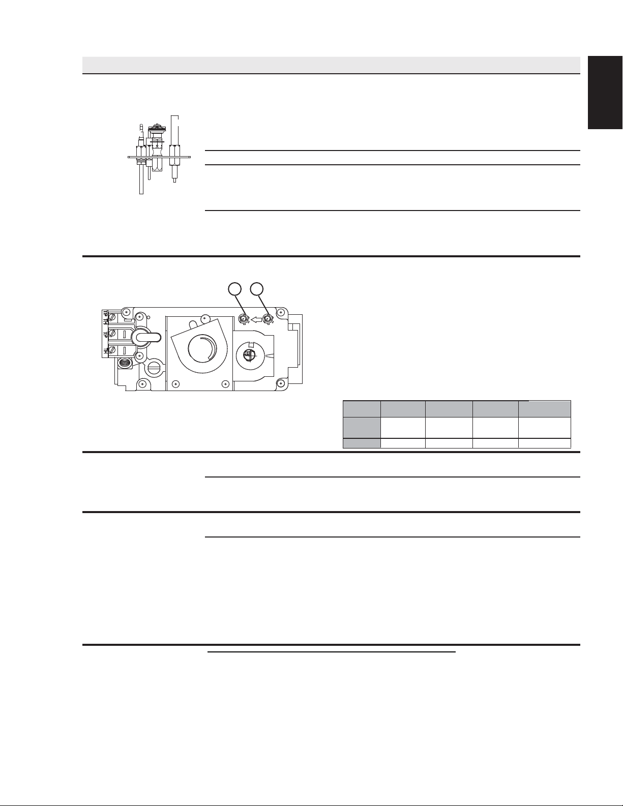
75
W415-1401 / C / 03.18.15
EN
SYMPTOM PROBLEM TEST SOLUTION
Pilot will not light. No spark at pilot burner. - Check if pilot can be lit by a match.
- Check that the wire is connected to the push button igniter.
- Check if the push button igniter needs tightening.
- Replace the wire if the wire insulation is broken or frayed.
- Replace the electrode if the ceramic insulator is cracked
or broken.
- Replace the push button ignitor
Out of propane gas. - Fill the tank.
Spark gap is incorrect. - Spark gap should be 0.150” (3.8mm) to 0.175” (4.5mm)
from the electrode tip and the pilot burner. To ensure
proper electrode location, tighten securing nut (fi nger
tight plus 1/4 turn).
No gas at the pilot burner. - Check that the manual valve is turned on.
- Check the pilot orifi ce for blockage.
- Replace the valve.
- Call the gas distributor.
Flames are consistently
too large or too small.
Carboning occurs.
Unit is over-fi red or underfi red. - Check pressure readings:
- Inlet pressure can be checked by turning screw (A)
counter-clockwise 2 or 3 turns and then placing pressure
gauge tubing over the test point. Gauge should read as
described on the chart below.
Check with main burner is
operating on ‘HI’.
- Outlet pressure can be checked the same as above
using screw (B). Gauge should read as described on the
chart below. Check that main burner is operating on ‘HI’.
- AFTER TAKING PRESSURE READINGS, BE SURE TO
TURN SCREWS CLOCKWISE FIRMLY TO RESEAL.
DO NOT OVER TORQUE.
- Leak test with a soap and water solution.
-
Flames are very aggressive. Door is ajar. - Ensure the mechanical means of securing the door is
providing a tight seal.
Venting action is too
great.
- Check to ensure venting is properly sealed.
- If restriction is required see “RESTRICTING VERTICAL
VENT” section.
Carbon is being
deposited on glass, logs
or combustion chamber
surfaces.
Air shutter has become
blocked.
- Ensure air shutter opening is free of lint or other
obstructions.
Flame is impinging on the logs
or combustion chamber.
- Check that the logs are correctly positioned.
- Open air shutter to increase the primary air.
- Check the input rate: check the manifold pressure and
orifi ce size as specifi ed by the rating plate values.
- Check that the door gasketing is not broken or missing
and that the seal is tight.
- Check that both vent liners are free of holes and well
sealed at all joints.
- Check that minimum rise per foot (meter) has been
adhered to for any horizontal venting.
42.3_2E
P
I
P
I
L
O
T
N
O
L
O
T
H
I
L
O
F
F
O
A
B
PILOT
BURNER
THERMOCOUPLE
THERMOPILE
Pressure
Inlet
Outlet
Natural Gas
(inches)
Natural Gas
(millibars)
Propane
(inches)
Propane
(millibars)
7"
(MIN. 4.5")
3.5"
13"
(MIN. 11")
10"
17.4mb
(MIN. 11.2mb)
8.7mb
32.4mb
(MIN. 27.4mb)
24.9mb

76
W415-1401 / C / 03.18.15
EN
42.3_3
SYMPTOM PROBLEM TEST SOLUTION
White / grey fi lm forms. Sulphur from fuel is being
deposited on glass, logs or
combustion chamber surfaces.
- Clean the glass with a recommended gas appliance
glass cleaner.
- DO NOT CLEAN GLASS WHEN HOT.
- If deposits are not cleaned off regularly, the glass may
become permanently marked.
Exhaust fumes smelled in
room, headaches.
Appliance is spilling. - Ensure exhaust bracket gasket seal.
- Check door seal and relief fl ap seal.
- Check for chimney blockage.
- Check that chimney is installed to building code.
- Room is in negative pressure; increase fresh air supply.
- Check cap gasket on the fl ue pipe assembly.
Remote wall switch is in
’OFF’ position; main burner
comes on when gas knob
is turned to ‘ON’ position.
Wall switch is mounted upside down.
- Reverse.
Remote wall switch is grounding.
- Replace.
Remote wall switch wire is grounding.
- Check for ground (short); repair ground or replace wire.
Faulty valve. - Replace.
77
W415-1401 / C / 03.18.15
EN
NAPOLEON® warrants its products against manufacturing defects to the original purchaser only. Registering your warranty is not necessary. Simply
provide your proof of purchase along with the model and serial number to make a warranty claim. NAPOLEON® reserves the right to have its
representative inspect any product or part thereof prior to honouring any warranty claim. Provided that the purchase was made through an authorized
NAPOLEON® dealer your appliance is subject to the following conditions and limitations:
Warranty coverage begins on the date of original installation.
This factory warranty is non-transferable and may not be extended whatsoever by any of our representatives.
The gas appliance must be installed by a licensed, authorized service technician or contractor. Installation must be done in accordance with the installation
instructions included with the product and all local and national building and fi re codes.
This limited warranty does not cover damages caused by misuse, lack of maintenance, accident, alterations, abuse or neglect and parts installed from
other manufacturers will nullify this warranty.
This limited warranty further does not cover any scratches, dents, corrosion or discoloring caused by excessive heat, abrasive and chemical cleaners nor
chipping on porcelain enamel parts, mechanical breakage of PHAZER™ logs and embers.
This warranty extends to the repair or replacement of warranted parts which are defective in material or workmanship provided that the product has been
operated in accordance with the operation instructions and under normal conditions.
After the fi rst year, with respect to this President’s Lifetime Limited Warranty, NAPOLEON® may, at its discretion, fully discharge all obligations with
respect to this warranty by refunding to the original warranted purchaser the wholesale price of any warranted but defective part(s).
NAPOLEON® will not be responsible for installation, labour or any other expenses related to the reinstallation of a warranted part and such expenses are
not covered by this warranty.
Notwithstanding any provisions contained in the President’s Lifetime Limited Warranty, NAPOLEON’S responsibility under this warranty is defi ned as
above and it shall not in any event extend to any incidental, consequential or indirect damages.
This warranty defi nes the obligations and liability of NAPOLEON® with respect to the NAPOLEON® gas appliance and any other warranties expressed or
implied with respect to this product, its components or accessories are excluded.
NAPOLEON® neither assumes, nor authorizes any third party to assume, on its behalf, any other liabilities with respect to the sale of this product.
NAPOLEON® will not be responsible for: over-fi ring, downdrafts, spillage caused by environmental conditions such as rooftops, buildings, nearby trees,
hills, mountains, inadequate vents or ventilation, excessive venting confi gurations, insuffi cient makeup air, or negative air pressures which may or may not
be caused by mechanical systems such as exhaust fans, furnaces, clothes dryers, etc.
Any damages to the appliance, combustion chamber, heat exchanger, plated trim or other components due to water, weather damage, long periods of
dampness, condensation, damaging chemicals or cleaners will not be the responsibility of NAPOLEON®.
All parts replaced under the President’s Limited Lifetime Warranty Policy are subject to a single claim.
During the fi rst 10 years NAPOLEON® will replace or repair the defective parts covered by the lifetime warranty at our discretion free of charge. From 10
years to life, NAPOLEON® will provide replacement parts at 50% of the current retail price.
All parts replaced under the warranty will be covered for a period of 90 days from the date of their installation.
The manufacturer may require that defective parts or products be returned or that digital pictures be provided to support the claim. Returned products are
to be shipped prepaid to the manufacturer for investigation. If a product is found to be defective, the manufacturer will repair or replace such defect.
Before shipping your appliance or defective components, your dealer must obtain an authorization number. Any merchandise shipped without
authorization will be refused and returned to sender.
Shipping costs are not covered under this warranty.
Additional service fees may apply if you are seeking warranty service from a dealer.
Warranty labour allowance is only for the replacement of the warranted part. Travel, diagnostic tests, shipping and other related charges are not covered
by this warranty.
2.1C
NAPOLEON® products are manufactured under the strict Standard of the world recognized ISO 9001 : 2008 Quality Assurance
Certifi cate.
NAPOLEON® products are designed with superior components and materials assembled by trained craftsmen who take great
pride in their work. The burner and valve assembly are leak and test-fi red at a quality test station. The complete appliance is
again thoroughly inspected by a qualifi ed technician before packaging to ensure that you, the customer, receives the quality
product that you expect from NAPOLEON®.
The following materials and workmanship in your new NAPOLEON® gas appliance are warranted against defects for as long as
you own the appliance. This covers: combustion chamber, heat exchanger, stainless steel burner, phazer™ logs and embers, rocks,
ceramic glass (thermal breakage only), gold plated parts against tarnishing, porcelainized enameled components and aluminum
extrusion trims.*
Electrical (110V and millivolt) components and wearable parts such as blowers, gas valves, thermal switch, switches, wiring, remote
controls, ignitor, gasketing, and pilot assembly are covered and NAPOLEON® will provide replacement parts free of charge during
the fi rst year of the limited warranty.*
Labour related to warranty repair is covered free of charge during the fi rst year. Repair work, however, requires the prior approval of
an authorized company offi cial. Labour costs to the account of NAPOLEON® are based on a predetermined rate schedule and any
repair work must be done through an authorized NAPOLEON® dealer.
* Construction of models vary. Warranty applies only to components included with your specifi c appliance.
NAPOLEON® GAS APPLIANCE PRESIDENT’S LIFETIME LIMITED WARRANTY
CONDITIONS AND LIMITATIONS
ALL SPECIFICATIONS AND DESIGNS ARE SUBJECT TO CHANGE WITHOUT PRIOR NOTICE DUE TO ON-GOING PRODUCT
IMPROVEMENTS. NAPOLEON® IS A REGISTERED TRADEMARK OF WOLF STEEL LTD.
AS REQUIRED BY THE DEPARTMENT OF ENERGY IN THE UNITED STATES, 10 CFR PART 430, THE WARRANTY IS VOID IF THIS
PRODUCT IS USED WITH A THERMOSTAT. THIS APPLIES TO PRODUCT INSTALLED IN THE UNITED STATES, ONLY.
22.0 WARRANTY
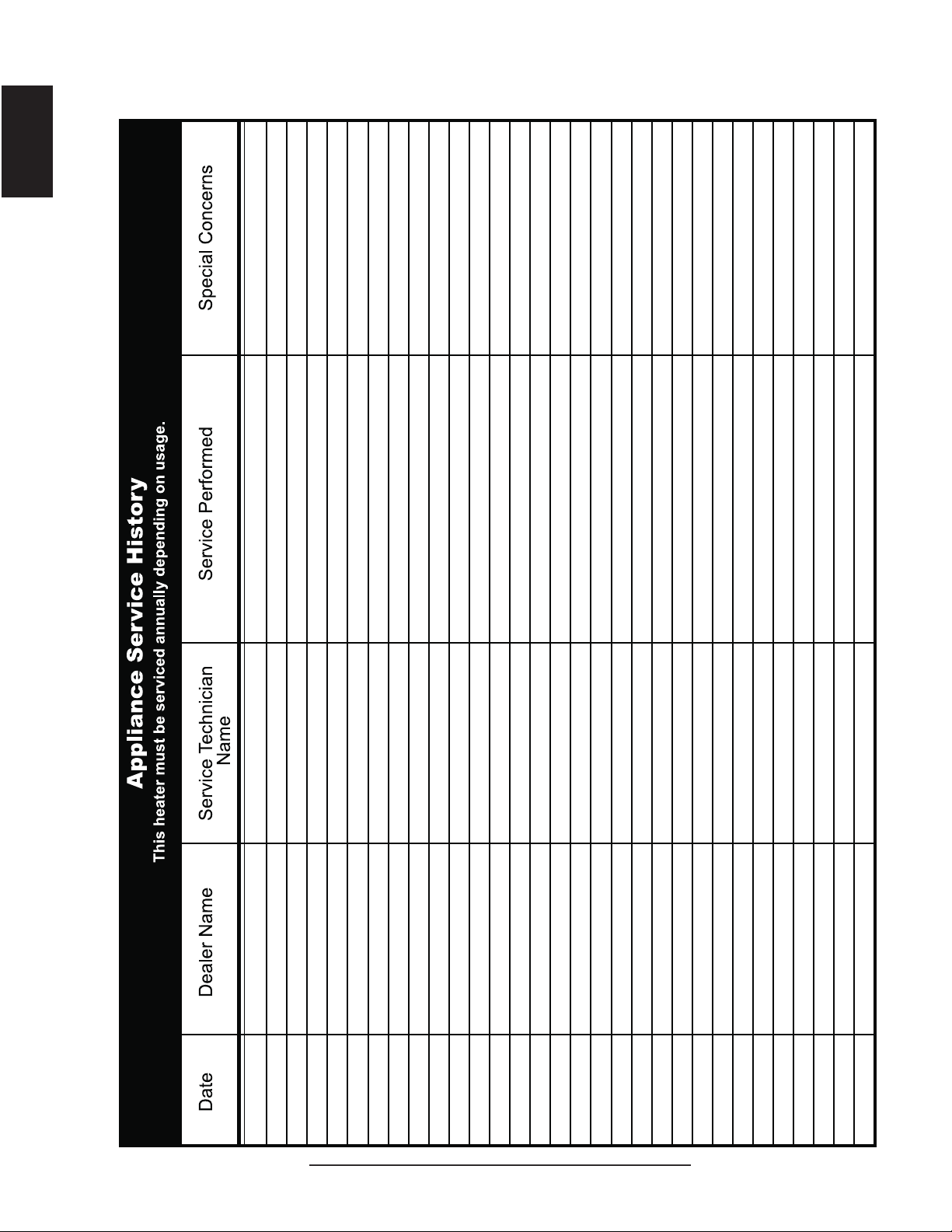
78
W415-1401 / C / 03.18.15
EN
43.1
23.0 SERVICE HISTORY

79
W415-1401 / C / 03.18.15
EN
24.0 NOTES
44.1
Other Napoleon
®
Products
'JSFQMBDF*OTFSUTt$IBSDPBM(SJMMT
t(BT'JSFQMBDFTt8BUFSGBMMTt8PPE4UPWFT
)FBUJOH$PPMJOHt&MFDUSJD'JSFQMBDFTt0VUEPPS'JSFQMBDFTt(BT(SJMMT
'JSFQMBDFT)FBUJOH$PPMJOHDBMMt(SJMMTDBMM
napoleonproducts.com
/BQPMFPO3PBE#BSSJF0OUBSJP$BOBEB-.(
#BZWJFX%SJWF#BSSJF0OUBSJP$BOBEB-/:
.JMMFS%SJWF$SJUUFOEFO,FOUVDLZ64"
5SBOT$BOBEB)JHIXBZ.POUSFBM2VFCFD$BOBEB)5"
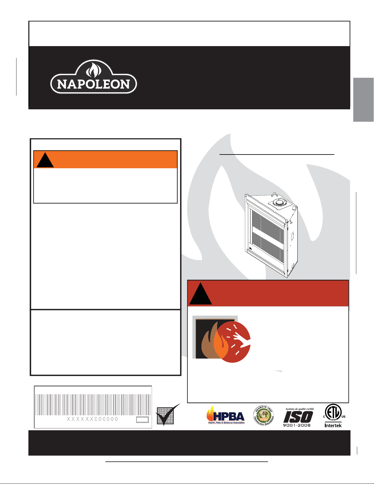
81
W415-1401 / C / 03.19.15
FR
INSTALLATEUR : LAISSEZ CE MANUEL AVEC L’APPAREIL.
PROPRIÉTAIRE : CONSERVEZ CE MANUEL POUR CONSULTATION ULTÉRIEURE.
NE LAISSEZ PAS LES ENFANTS OU AUTRES INDIVIDUS À RISQUE SEULS À PROXIMITÉ DE L’APPAREIL.
INSTRUCTIONS
D’INSTALLATION ET
D’OPÉRATION
1.28D
Wolf Steel Ltd., 24 Napoleon Rd., Barrie, ON, L4M 0G8 Canada /
103 Miller Drive, Crittenden, Kentucky, USA, 41030
Téléphone 705-721-1212 • Télécopieur 705-722-6031 • www.napoleonfoyers.com • [email protected]
10,00$
CERTIFIÉ POUR LE CANADA ET LES ÉTATS-UNIS SELON LES MÉTHODES ANSI/CSA.
CONSIGNES DE SÉCURITÉ
!
AVERTISSEMENT
- N’entreposez pas et n’utilisez pas d’essence ou autres
liquides et vapeurs infl ammables à proximité de cet ap-
pareil ou tout autre appareil.
- QUE FAIRE SI VOUS DÉTECTEZ UNE ODEUR DE GAZ :
• N’allumez aucun appareil.
• Ne touchez à aucun interrupteur électrique;
n’utilisez aucun téléphone dans votre immeuble.
• Appelez immédiatement votre fournisseur de gaz
d’un téléphone voisin. Suivez ses instructions.
• Si vous ne pouvez pas rejoindre votre fournisseur
de gaz, appelez le service des incendies.
- L’installation et l’entretien doivent être faits par un
installateur qualifi é, une agence d’entretien ou le
fournisseur.
Cet appareil peut être installé dans une maison
préfabriquée (mobile) déjà instalée à demeure si les
règlements locaux le permettent.
Cet appareil doit être utilisé uniquement avec le type de
gaz indiqué sur la plaque signalétique. Cet appareil ne
peut être converti à d’autres gaz, sauf si une trousse de
conversion est utilisée.
Si ces instructions ne sont pas suivies à la
lettre, un incendie ou une explosion pourraient
s’ensuivre, causant des dommages matériels,
des blessures corporelles ou des pertes de vie.
APPOSEZ L’ÉTIQUETTE DU NUMÉRO DE SÉRIE DU CARTON
N° de série
N° DE MODÈLE
Produit décoratif : Ne pas utiliser comme appareil de chauffage.
LA VITRE CHAUDE CAUSERA
DES BRÛLURES.
NE PAS TOUCHER LA VITRE
AVANT QU’ELLE AIT REFROIDI.
NE JAMAIS LAISSER LES
ENFANTS TOUCHER LA VITRE.
!
AVERTISSEMENT
Une barriére conçu à réduire le risque de brûlures
causées par le verre chaud est fourni avec l’appareil
et sera installé pour la protection des enfants et
d’autres personnes à risque.
ÉCRAN DE
PROTECTION
CONFORME AUX LES NORMES NATIONALES AMÉRICAINES: ANSI Z21.50, CERTIFIE CANADIENNES: CSA 2.22 FOYER À GAZ VENTILÉ.
B36 ILLUSTRÉ
ÉCRAN DE PROTECTION
B36NT / B36NTE &
GX36NT / GX36NTE
MODÉLE AU GAZ NATUREL
B36PT / B36PTE &
GX36PT / GX36PTE
MODÉLE AU PROPANE

82
W415-1401 / C / 03.19.15
FR
NOTE : Les modifi cations, autres qu’éditoriales, sont indiquées par une ligne verticale dans la marge.
TABLE DES MATIÈRES
NOTE: L'icône du camera indique que les vidéos sont disponibles comme une référence supplémentaire,
visitez http://www.napoleonfi replaces.com/category/product-support/support-centre/
1.0 VUE D'ENSEMBLE DE L'INSTALLATION 83
2.0 INTRODUCTION 84
2.1 DIMENSIONS 85
2.2 INSTRUCTIONS GÉNÉRALES 86
2.3 INFORMATIONS GÉNÉRALES 87
2.4
INFORMATION À PROPOS DE LA PLAQUE D’HOMOLOGATION 88
3.0 ÉVACUATION 89
3.1 LONGUEURS DES CONDUITS D’ÉVACUATION ET COMPOSANTS 90
3.2 INSTALLATIONS TYPIQUES D'ÉVENTS 91
3.3 INSTALLATIONS PARTICULIÈRES D'ÉVENTS 93
3.3.1 ENSEMBLE PÉRISCOPIQUE 93
3.3.2 INSTALLATION EN COIN 93
3.4 EMPLACEMENTS ET DÉGAGEMENTS MINIMAUX DE LA TERMINAISON 94
3.5 CHARTE D'APPLICATION DES ÉVACUATIONS 95
3.6 LÉGENDE 96
3.7 VALEURS DU COUDE EN LONGUEURS D'ÉVENT 96
3.8 ÉVACUATION SUR LE DESSUS TERMINAISON HORIZONTAL 97
3.9 ÉVACUATION À L'ARRIÈRE TERMINAISON HORIZONTALE 99
3.10 ÉVACUATION SUR LE DESSUS OU À L'ARRIÈRE TERMINAISON VERTICALE 101
3.11 ÉVACUATION À L'ARRIÈRE 103
3.12 ÉVACUATION SUR LE DESSUS 104
4.0 INSTALLATION 105
4.1 PROTECTION DU MUR ET DU PLAFOND 105
4.1.1 INSTALLATION HORIZONTALE 106
4.1.2 INSTALLATION VERTICALE 106
4.2 UTILISATION DE COMPOSANTS FLEXIBLES D’ÉVACUATION 107
4.2.1 INSTALLATION DE LA TERMINAISON HORIZONTALE 107
4.2.2 INSTALLATION DE LA TERMINAISON VERTICALE 108
4.2.3 RACCORDEMENT DES ÉVENTS À L'APPAREIL 108
4.3 UTILISATION DE COMPOSANTS RIGIDES D’ÉVACUATION 109
4.3.1 INSTALLATION DE LA TERMINAISON HORIZONTALE 109
4.3.2 INSTALLATION DE LA TERMINAISON VERTICALE 110
4.4 RESTREIGNANT DES ÉVENTS VERTICAUX 110
4.5 TERMINAISON VERTICALE À TRAVERS UNE CHEMINÉE EXISTANTE 111
4.6 INSTALLATION DANS UNE MAISON MOBILE 112
4.7 BRANCHEMENT DU GAZ 113
4.8 INTERRUPTEUR MURAL OPTIONNEL 113
5.0 OSSATURE 114
5.1 L'OSSATURE B36 114
5.1.1 DIMENSIONS MINIMALES DE L’OSSATURE B36 115
5.2 DÉGAGEMENTS MINIMAUX DE L'ENCEINTE B36 117
5.3 L'OSSATURE GX36 121
5.3.1 DIMENSIONS MINIMALES DE L’OSSATURE GX36 122
5.4 INSTALLATION EN ALCÔVE 128
5.5 MATÉRIAU DE FINITION INCOMBUSTIBLE 129
5.6 DÉGAGEMENTS MINIMAUX DE LA TABLETTE 130
5.7 INSTALLATION SUPPORT DE FIXATION 130
6.0 FINITIONS 131
6.1 OUVERTURE ET FERMETURE DE LA PORTE ET L'ÉCRAN DE PROTECTION 131
6.2 DISPOSITION DES BÛCHES 132
6.3 MISE EN PLACE DU LOGO 133
6.4 D’INSTALLATION DU SAUVEGARDE DE PILE 133
6.5 D’INSTALLATION DU SOUFFLERIE 134
6.6 SCHÉMA DE CÂBLAGE 135
7.0 FONCTIONNEMENT 136
7.1 B36NTRE/GX36NTRE & B36PTRE/GX36PTRE (ELECTRONIQUE) 136
8.0 FONCTIONNEMENT 137
8.1 B36NTR/GX36NTR & B36PTR/GX36PTR (MILLIVOLT) 137
9.0 RÉGLAGES 138
9.1 RÉGLAGE DE LA VEILLEUSE 138
9.2 RÉGLAGE DU VENTURI 138
10.1 CARACTÉRISTIQUES DE LA FLAMME 139
10.0 ENTRETIEN 139
10.2 ENTRETIEN ANNUEL 140
10.3 REMPLACEMENT DE LA VITRE DE PORTE 141
10.4 SOINS DE LA VITRE 141
11.0 RECHANGES 142
12.0 VUE D'ENSEMBLE DE B36 143
13.0 L'ASSEMBLAGE DE LA SOUPAPE DE ELECTRONIQUE B36 144
14.0 L'ASSEMBLAGE DE LA SOUPAPE DE MILLIVOLT B36 145
15.0 ACCESSORIES B36 146
16.0 VUE D'ENSEMBLE DE GX36 147
17.0 L'ASSEMBLAGE DE LA SOUPAPE DE MILLIVOLT GX36 148
18.0 L'ASSEMBLAGE DE LA SOUPAPE DE ELECTRONIQUE GX36 149
19.0 ACCESSORIES GX36 150
20.0 GUIDE DE DÉPANNAGE (ÉLÉCTRONIQUE) 152
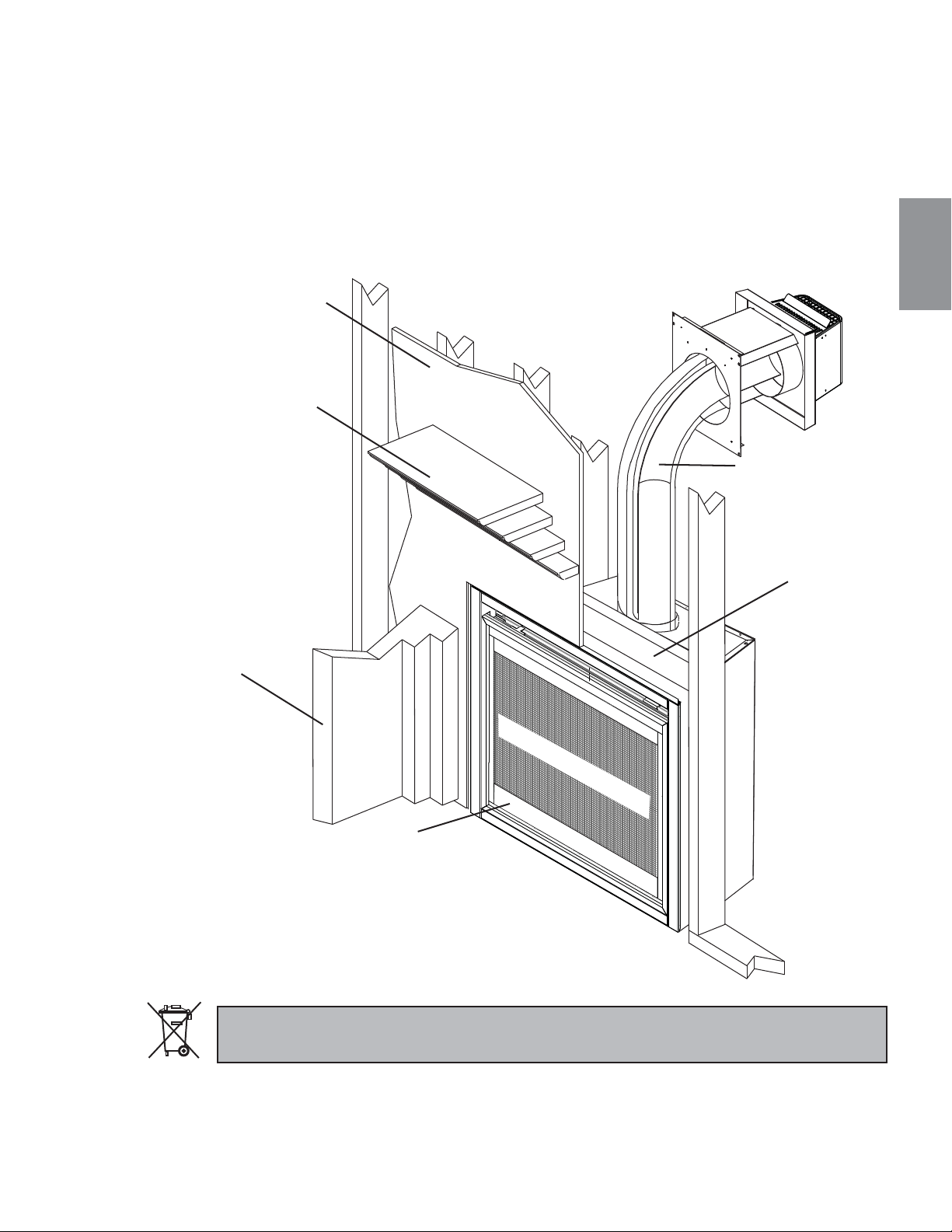
83
W415-1401 / C / 03.19.15
FR
1.0 VUE D'ENSEMBLE DE L'INSTALLATION
Voir la section
« DÉGAGEMENTS MINIMAUX
DE L’ENCEINTE » pour les
cloisons sèches (ou autre
matériau combustible).
Voir la section
« DÉGAGEMENTS
MINIMAUX DE LA
TABLETTE ».
Voir la section
«MATÉRIAU DE
FINITION
INCOMBUSTIBLE ».
Mur
latéral
Voir la section
« OSSATURE ».
Voir les sections
« ÉVACUATION » et
« INSTALLATION ».
Voir la section
« INSTALLATION DES
PERSIENNES ».
B36 ILLUSTRÉ
ÉCRAN DE PROTECTION
Les piles doivent être mises au rebut conformément aux lois et à la réglementation locales. Certaines piles
peuvent être recyclées et acceptées dans votre centre de recyclage local. Renseignez-vous auprès de
votre municipalité au sujet des directives de recyclage.
21.0 GUIDE DE DÉPANNAGE (MILLIVOLT) 155
22.0 GARANTIE 158
23.0 HISTORIQUE D’ENTRETIEN 159
!
AVERTISSEMENT
3.1D
• CET APPAREIL EST CHAUD LORSQU’IL FONCTIONNE ET PEUT CAUSER DE GRAVES BRÛLURES EN CAS DE
CONTACT.
• TOUTE MODIFICATION APPORTÉE À CET APPAREIL OU AUX CONTRÔLES PEUT ÊTRE DANGEREUX ET EST
INTERDIT.
• Ne faites pas fonctionner l’appareil avant d’avoir lu et compris les instructions d’opération. Omettre d’utiliser l’appareil selon les
instructions d’opération pourrait causer un incendie ou des blessures.
• Risque d’incendie ou d’asphyxie. Ne faites pas fonctionner l’appareil avec la vitre retirée.
• Ne branchez pas la soupape à du courant 110 volts.
• Risque de brûlures. L’appareil doit être éteint et refroidi avant d’effectuer un entretien.
• N’installez pas de composants endommagés ou incomplets ni des composants substituts.
• Risque de coupures et d’érafl ures. Portez des gants protecteurs et des lunettes de sécurité lors de l’installation. Les bordures
des pièces de métal peuvent être coupantes.
• Ne brûlez pas de bois ou autres matériaux dans cet appareil.
• Les enfants et les adultes devraient être informés des dangers que posent les températures de surface élevées
et se tenir à distance afin d’éviter des brûlures ou que leurs vêtements ne s’enflamment.
• Les jeunes enfants doivent être supervisés attentivement lorsqu’ils sont dans la même pièce que l’appareil. Les jeunes
enfants et autres personnes sont sujets aux brûlures accidentelles. Une barrière de protection est recommandée si des
individus à risque se trouvent dans la maison. Afi n de restreindre l’accès à l’appareil, installez une barrière de protection
ajustable pour garder les jeunes enfants ou autres personnes à risque hors de la pièce et loin des surfaces chaudes.
• Les vêtements et autres matériaux combustibles ne doivent pas être posés sur l’appareil ou à proximité.
• En raison des températures élevées, l’appareil devrait être placé loin des endroits passants et loin des meubles et des rideaux.
• Assurez-vous de disposer de mesures de sécurité adéquates pour empêcher les jeunes enfants de toucher aux surfaces
chaudes.
• Même une fois que l’appareil est éteint, la vitre et/ou le pare-étincelles demeureront chauds pendant un temps prolongé.
• Consultez votre détaillant local de foyer pour connaître les grillages de sécurité et les écrans offerts pour protéger les enfants des
surfaces chaudes. Ces grillages de sécurité et ces écrans doivent être fi xés au plancher.
• Tout grillages de sécurité, écrans ou barriére enlevés pour faire l’entretien devront être remis en place avant d’utiliser l’appareil.
• Cet appareil est un appareil à gaz ventilé. Ne brûlez pas de bois ou autres matériaux dans cet appareil.
• Il est primordial de garder propres les compartiments de contrôle, les brûleurs, la souffl erie, les bouches d’air de l’appareil ainsi
que le système d’évacuation. L’appareil et son système d’évacuation doivent être inspectés avant la première utilisation et au
moins une fois l’an par un spécialiste en entretien. Un entretien plus fréquent pourrait être nécessaire en raison des peluches
provenant des tapis, literie, etc. L’emplacement de l’appareil doit être gardé libre de tous matériaux combustibles, essence ou
autres liquides et vapeurs infl ammables.
• Cet appareil ne devra être modifi é en aucun cas.
• Cet appareil ne doit pas être raccordé au conduit d’une cheminée desservant un autre appareil de chauffage à combustible
solide.
• N’utilisez pas cet appareil si une partie quelconque a été submergée. Contactez immédiatement un technicien de service qualifi é
pour inspecter l’appareil et pour remplacer toute pièce du système de contrôle et du contrôle du gaz qui aurait été submergée.
• Ne pas opérer l’appareil lorsque la porte vitrée est enlevée, fi ssurée ou brisée. Le remplacement de la vitre devra être effectué
par un technicien de service certifi é ou qualifi é.
• Ne frappez pas et ne claquez pas la porte vitrée de appareil.
• Lorsque l’appareil est muni de portes d’évacuation de pression, elles doivent demeurer fermées pendant le fonctionnement de
l’appareil afi n d’empêcher les gaz de combustion contenant du monoxyde de carbone de s’infi ltrer dans la maison.
• Seules les portes/façades certifi ées pour cet appareil peuvent être utilisées avec cet appareil.
• Gardez les matériaux d’emballage hors de la portée des enfants et mettez ces matériaux au rebut de façon sécuritaire. Comme
tous les emballages de plastique, ces matériaux ne sont pas des jouets et doivent demeurer hors de la portée des enfants et des
bébés.
• Comme dans le cas de tout appareil à combustion, il est recommandé de faire inspecter et entretenir votre appareil
régulièrement. De même, installez un détecteur de monoxyde de carbone dans la pièce pour vous protéger, ainsi que votre
famille, contre les intoxications.
• Assurez-vous de respecter les dégagements aux matériaux combustibles lorsque vous installez un manteau ou des tablettes
au-dessus de l’appareil. Les téléviseurs et autres composants électroniques soumis à des températures élevées peuvent fondre,
se déformer, se décolorer et entraîner des défaillances prématurées de ces appareils.
• Cet appareil utilise et requiert un thermocouple à action rapide. Remplacez uniquement par un thermocouple à action rapide de
Wolf Steel ltée.
• Une barriére conçu à réduire le risque de brûlures causées par le verre chaud est fourni avec l’appareil et sera installé.
• Si la barriére est endommagée, elle devra être remplacée par la barriére conçu par le manufacturier pour cet appareil.
• L’installation et la réparation devraient être effectuées par un technicien qualifi é. L’appareil et son système d’évacuation
devraient être inspectés avant l’utilisation initiale et au moins une fois l’an par un professionel qualifi é. Un nettoyage
plus réquent peut être requis en raison de la poussière excessive laissée par les moquettes, les couvertures, etc. Il est
impératif que les compartiments de contrôle, le brûleur et les passages de circulation d’air soient gardés propres afi n de
fourni une combustion et une circulation d’air adéquates.
84
W415-1401 / C / 03.19.15
FR
2.0 INTRODUCTION
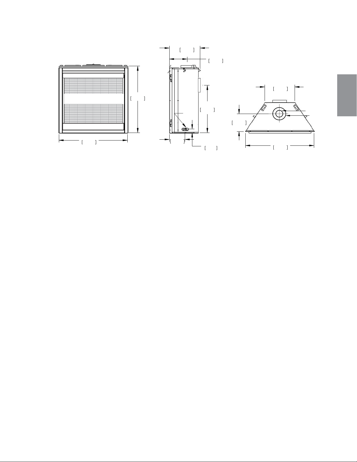
34 1/16"
866mm
35"
890mm
15 3/4"
400mm
24"
610mm
9 1/16"
230mm
8"
203mm
1 15/16"
49mm
GAS
INLET
15 3/8"
391mm
35"
889mm
9 1/16"
230mm
SAFETY BARRIER
4" [102mm]
7" [178mm]
ÉCRAN DE PROTECTION
85
W415-1401 / C / 03.19.15
FR
2.1 DIMENSIONS
4.1B
CET APPAREIL AU GAZ DEVRAIT ÊTRE INSTALLÉ ET ENTRETENU PAR UN INSTALLATEUR QUALIFIÉ en se conformant
aux codes locaux. Les pratiques d’installation peuvent varier d’une région à l’autre. Il est donc important de connaître les normes
spécifi ques qui s’appliquent à votre région. Par exemple dans l’état du Massachusetts:
• Ce produit doit être installé par un plombier certifi é ou un installateur pour le gaz lorsque installé dans le Commonwealth du Mas-
sachusetts.
• Le registre de l’appareil doit être enlevé ou bloqué en le soudant en position ouverte avant d’installer un encastré ou un ensemble
de bûches à gaz.
• La soupape d’arrêt doit être un robinet à gaz avec une poignée en T.
• Le raccord fl exible ne doit pas mesurer plus que 36 pouces (914.4mm).
• Un détecteur de monoxyde de carbone est requis dans toutes les pièces contenant des appareils alimentés au gaz.
• L’appareil n’est pas approuvé pour installation dans une chambre à coucher ou une salle de bain à moins d’être un appareil avec
une chambre de combustion scellée à évacuation directe.
L’installation doit se conformer aux codes locaux. En l’absence de codes locaux, l’installation doit être conforme au Code
d’installation du gaz naturel et du propane CSA B149.1 au Canada ou au National Fuel Gas Code, ANSI Z223.1/ NFPA 54 aux
États-Unis. Cet appareil convient pour installation dans une maison mobile si l’installation est conforme aux normes actuelles pour
les maisons mobiles équipées au gaz CAN/CSA Z240 SÉRIE MM au Canada ou selon les normes ANSI Z223.1 et NFPA 54 aux
États-Unis.
Tant que les distances requises pour les dégagements aux matériaux
combustibles sont respectées, le meilleur endroit pour un appareil est le
centre de la maison, car ceci permet une meilleure utilisation de la chaleur
fournie. L’emplacement des fenêtres, des portes et la circulation dans la
pièce où se trouve l’appareil devront être pris en considération. Si possible,
vous devriez choisir un emplacement où le système d’évent peut passer à
travers la maison sans avoir à découper des solives de plancher ou de toit.
Si l’appareil est installé directement sur un tapis, sur une surface de vinyle
ou tout autre revêtement de plancher combustible autre que le bois,
l’appareil devra être monté sur un panneau continu de métal ou de bois se
prolongeant sur toute la largeur et la profondeur.
Certains appareils ont une souffl erie ou un ensemble de deux souffl eries optionnel. Si la souffl erie ou l’ensemble de deux
souffl eries optionnel est installé, la boîte de dérivation doit être branchée au circuit électrique et mise à la terre conformément aux
codes locaux. Utilisez la version courante du Code canadien de l’électricité CSA C22.1 au Canada ou le National Electrical Code
A
NSI/NFPA 70 aux États-Unis.
Nous suggérons que nos
appareils au gaz soient installés
et que l'entretien soit effectué
par des professionnels certi-
fiés par le National Fireplace
Institute® (NFI) comme
spécialiste du gaz NFI.
ALLUMEZ TOUJOURS LA VEILLEUSE, QUE CE SOIT POUR LA PREMIÈRE FOIS OU LORSQUE
L’APPROVISIONNEMENT EN GAZ EST ÉPUISÉ, AVEC LA PORTE VITRÉE OUVERTE OU RETIRÉE.
PRÉVOYEZ UN ACCÈS SUFFISANT POUR ENTRETENIR ET OPÉRER L’APPAREIL.
ASSUREZ-VOUS D'UNE QUANTITÉ SUFFISANTE D’AIR DE VENTILATION.
N’OBSTRUEZ JAMAIS L’OUVERTURE DE L’APPAREIL.
LES OBJETS PLACÉS DEVANT L’APPAREIL DOIVENT ÊTRE GARDÉS À UNE DISTANCE D'AU MOINS 48"
(1219.2mm) DE LA FACE VITRÉE DE L'APPAREIL.
LES SURFACES AUTOUR ET SURTOUT AU-DESSUS DE L’APPAREIL PEUVENT DEVENIR CHAUDES. NE
TOUCHEZ PAS L’APPAREIL QUAND IL FONCTIONNE.
RISQUE D’INCENDIE OU D’EXPLOSION.
LES PRESSIONS ÉLEVÉES ENDOMMAGERONT LA SOUPAPE. L’ALIMENTATION EN GAZ DOIT ÊTRE DÉBRAN-
CHÉE PENDANT LES ESSAIS DE PRESSION DE CE SYSTÈME LORSQUE LES PRESSIONS D’ESSAI EXCÈDENT
½ LB/PO² (3,5 KPA). FERMEZ LA SOUPAPE D’ARRÊT MANUELLE PENDANT TOUT ESSAI DE PRESSION DU
SYSTÈME D’ALIMENTATION EN GAZ LORSQUE LA PRESSION EST DE ½ LB/PO² (3,5 mb) OU MOINS.
N’UTILISEZ QUE LES ACCESSOIRES OPTIONNELS ET LES PIÈCES DE RECHANGE APPROUVÉS PAR WOLF
STEEL POUR CET APPAREIL. L’UTILISATION D’ACCESSOIRES NON LISTÉS (SOUFFLERIE, PORTES, PER-
SIENNES, MOULURES, COMPOSANTS DE GAZ, COMPOSANTS D’ÉVACUATION, ETC.) POURRAIT ÊTRE NON
SÉCURITAIRE ET ANNULERA LA GARANTIE ET LA CERTIFICATION.
!
AVERTISSEMENT
86
W415-1401 / C / 03.19.15
FR
2.2 INSTRUCTIONS GÉNÉRALES
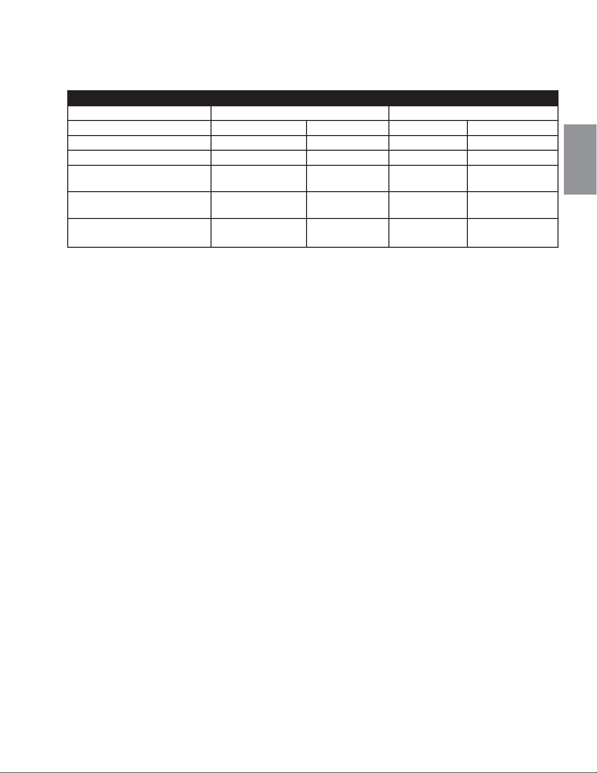
87
W415-1401 / C / 03.19.15
FR
2.3 INFORMATIONS GÉNÉRALES
POUR VOTRE SATISFACTION, CET APPAREIL A ÉTÉ MIS À L'ESSAI POUR CONFIRMER SON
FONCTIONNEMENT ET SA QUALITÉ!
Cet appareil est approuvé pour installation dans les salles de bain, les chambres à coucher ou les chambres
studio et convient pour installation dans les maisons mobiles.
Aucune alimentation électrique externe (110 volts ou 24 volts) n'est requise pour le millivolt
fonctionnement du système.
Les bruits causés par l'expansion et la contraction lors des cycles de chauffage et de refroidissement
sont tout à
fait normaux et il faut s'y attendre.
Une barrière conçu à réduire le risque de brûlures à partir de le chaude la vitre est à condition que
avec l’appareil et sera être installés.
RENDEMENTS ET EFFICACITÉS
B36 GX36
GN PL GN PL
Altitude (PI) 0-4,500 0-4500 0-4,500 0-4500
Débit max. (BTU/H) 18,000 18,000 26,000 26,000
Pression minimale
d'alimentation en gaz
4.5" (11mb) w.c. 11" (27mb) w.c. 4.5" (11mb) w.c. 11" (27mb) w.c.
Pression maximale
d'alimentation en gaz
7" (17mb) w.c. 13" (32mb) w.c. 7" (17mb) w.c. 13" (32mb) w.c.
Pression au collecteur (lorsque
le gaz circule)
3.5" (9mb) w.c. 10" (25mb) w.c. 3.5" (9mb) w.c. 10" (25mb) w.c.
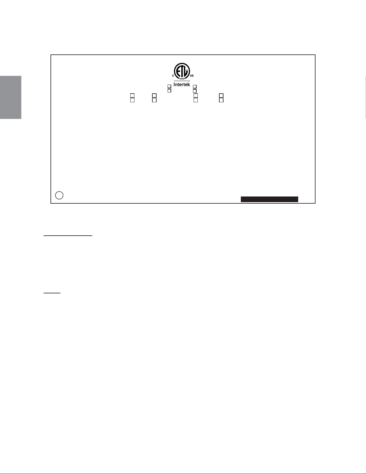
ÉCHANTILLON
W385-1987
FOYER À GAZ VENTILÉ DIRECT. HOMOLOGUE POUR INSTALLATION DANS UNE CHAMBRE A COUCHER,
UNE SALLE DE BAIN ET UN STUDIO. APPROPRIE POUR INSTALLATION DANS UNE MAISON MOBILE SI
SON INSTALLATION CONFORME AUX EXIGENCES DE LA NORME CAN/CSA Z240MH SERIE DE MAISONS
MOBILES EQUIPEES AU GAZ, EN VIGUEUR AU CANADA OU AUX ETATS-UNIS DE LA NORME DE
SECURITE ET DE CONSTRUCTION DE MAISONS MANUFACTUREES, TITRE 24 CFR, SECTION 3280.
DANS LE CAS OU CETTE NORME D'ETATS-UNIS NE PEUT ETRE APPLIQUEE, SE REFERER A LA NORME
RELATIVE AU CRITERE DE MESURES DE SECURITE CONTRE L'INCENDIE POUR LES INSTALLATIONS
DANS LES MAISONS MANUFACTURES, LES SITES ET LES COMMUNAUTES, ANSI/NFPA 501A.
POUR
UNE UTILISER AVEC BARRIÈRE W565-0144. SUIVEZ LES INSTRUCTIONS
D'INSTALLATION SE TROUVENT DANS LE MANUEL D'INSTALLATION
DIRECT VENT GAS FIREPLACE. SUITABLE FOR BEDROOM, BATHROOM AND BED-SITTING ROOM
INSTALLATION. SUITABLE FOR MOBILE HOME INSTALLATION IF INSTALLED IN ACCORDANCE
WITH THE CURRENT STANDARD CAN/CSA Z240MH SERIES GAS EQUIPPED MOBILE HOMES,
IN CANADA OR IN THE UNITED STATES THE MANUFACTURED HOME CONTRUCTION AND
SAFETY STANDARD, TITLE 24 CFR, PART 3280. WHEN THIS US STANDARD IS NOT
APPLICABLE USE THE STANDARD FOR FIRE SAFETY CRITERIA FOR MANUFACTURED
HOME INSTALLATIONS, SITES AND COMMUNITIES, ANSI / NFPA 501A.
FOR USE WITH BARRIER
W565-0144. FOLLOW THE INSTALLATION INSTRUCTIONS LOCATED IN THE INSTALLATION MANUAL.
9700539 (WSL) 4001657 (NGZ)
4001658 (NAC) 4001659 (WUSA)
0-4500FT (0-1370m) ALTITUDE / ELEVATION 0-4500FT (0-1370m)
18,000 BTU/h INPUT / ALIMENTATION 18,000 BTU/h
13,000 BTU/h REDUCED INPUT / ALIMENTATION REDUITE 13,500 BTU/h
MANIFOLD PRESSURE: 3.5" (9MB) WATER COLUMN MANIFOLD PRESSURE: 10" (25MB) WATER COLUMN
PRESSION AU COLLECTEUR: 3.5" (9 MB) D'UNE COLONNE D'EAU PRESSION AU COLLECTEUR: 10" (25MB) D'UNE COLONNE D'EAU
MINIMUM SUPPLY PRESSURE: 4.5" (11MB) WATER COLUMN MINIMUM SUPPLY PRESSURE: 11" (27MB) WATER COLUMN
PRESSION D'ALIMENTATION MINIMALE: 4.5" (11MB) D'UNE COLONNE D'EAU PRESSION D'ALIMENTATION MINIMALE: 11" (27MB) D'UNE COLONNE D'EAU
MAXIMUM SUPPLY PRESSURE: 7.0" (17MB) WATER COLUMN MAXIMUM SUPPLY PRESSURE: 13" (32MB) WATER COLUMN
PRESSION D'ALIMENTATION MAXIMALE: 7.0" (17MB) D'UNE COLONNE D'EAU PRESSION D'ALIMENTATION MAXIMALE: 13" (32MB) D'UNE COLONNE D'EAU
P4: 51.7% P4: 51.7%
NOT FOR USE WITH SOLID FUEL. FOR USE WITH GLASS DOORS
CERTIFIED WITH THIS UNIT ONLY.
WARNING:
THIS FIREPLACE USES AND REQUIRES A FAST ACTING THERMOCOUPLE. REPLACE
ONLY WITH A FAST ACTING THERMOCOUPLE SUPPLIED BY WOLF STEEL LTD.
DO NOT ADD ANY MATERIAL TO THE APPLIANCE, WHICH WILL COME IN CONTACT WITH THE FLAMES,
OTHER THAN THAT SUPPLIED BY THE MANUFACTURER WITH THE APPLIANCE. MINIMUM CLEARANCE
TO COMBUSTIBLE MATERIALS /
DEGAGEMENTS MINIMAUX DES MATERIAUX COMBUSTIBLES:
TOP/ DESSUS 0 RECESSED DEPTH / PROFONDEUR D'ENCASTRE 16"
FLOOR / PLANCHER 0 VENT SIDES / COTES DE L'EVENT 1"
SIDES / COTES 0 VENT TOP / EVENT SUPERIEUR 3"
BACK / ARRIERE 0 VENT BOTTOM / EVENT INFERIEUR 1"
MANTEL / MANTEAU 2" *
* MAXIMUM HORIZONTAL EXTENSION / L'EXTENSION HORIZONTALE MAXIMALE: 2". SEE INSTRUCTION
MANUAL FOR GREATER EXTENSIONS. REFERER AU MANUEL D'INSTRUCTION POUR DES
EXTENSIONS PLUS GRANDES.
SEE OWNER'S INSTRUCTION MANUAL FOR MINIMUM AND MAXIMUM VENT LENGTHS.
REFERER AU MANUEL D'INSTALLATION DE PROPRIETAIRE POUR LES LONGUEURS
D'EVACUATION MINIMALE ET MAXIMALE.
WOLF STEEL LTD.
24 NAPOLEON ROAD, BARRIE, ON, L4M 0G8 CANADA
UN COMBUSTIBLE SOLIDE NE DOIT PAS ETRE UTILISE AVEC CET
APPAREIL. UTILISER AVEC LES PORTES VITREES HOMOLOGUEES
SEULEMENT AVEC CETTE UNITE.
AVERTISSEMENT: CE FOYER UTILISE ET REQUIERT UN THERMOCOUPLE À ACTION RAPIDE.
REMPLACEZ UNIQUEMENT AVEC UN THERMOCOUPLE À ACTION RAPIDE DE WOLF STEEL LTÉE.
N’AJOUTEZ PAS A CET APPAREIL AUCUN MATERIAU DEVANT ENTRER EN CONTACT AVEC LES FLAMMES
AUTRE QUE CELUI QUI EST FOURNI AVEC CET APPAREIL PAR LE FABRICANT.
THE APPLIANCE MUST BE VENTED USING THE APPROPRIATE WOLF STEEL VENT KITS. SEE OWNERS
INSTALLATION MANUAL FOR VENTING SPECIFICS. PROPER REINSTALLATION AND RESEALING IS
NECESSARY AFTER SERVICING THE VENT-AIR INTAKE SYSTEM.
L'APPAREIL DOIT EVACUER SES GAZ EN UTILISANT L'ENSEMBLE D'EVACUATION PROPRE A NAPOLEON.
REFERER AU MANUEL D'INSTALLATION DE PROPRIETAIRE POUR L'EVACUATION PRECISE. IL EST
IMPORTANT DE BIEN REINSTALLER ET RESCELLER L'EVENT APRES AVOIR ASSURE LE MAINTIEN DU
SYSTEME DE PRISE D'AIR.
DECORATIVE PRODUCT: NOT FOR USE AS A HEATING APPLIANCE
PRODUIT DÉCORATIF: NE PAS UTILISER COMME APPPAREIL DE CHAUFFAGE.
ELECTRICAL RATING / CLASSIFICATION: 115V 0.82AMP, 60HZ
OPTIONAL FAN KIT / ENSEMBLE DE VENTILATEUR FACULTATIF: EP35
SERIAL NUMBER/NO. DE SERIE:
B36
B36NTR CB36NTR MODEL CB36PTR B36PTR
B36NTRE CB36NTRE CB36PTRE B36PTRE
CONFORMS TO / CONFORME AUX: ANSI Z21.50-2014, CERTIFIED TO / CERTIFIE CSA 2.22-2014 VENTED GAS FIREPLACE / FOYER À GAZ VENTILÉ.
88
W415-1401 / C / 03.19.15
FR
2.4 INFORMATION À PROPOS DE LA PLAQUE D’HOMOLOGATION
INSTALLATEUR : Il est de votre responsabilité de cocher les cases appropriées sur la plaque
d'homologation correspondant au modèle, au type d'évacuation et au type de gaz de l'appareil.
Pour l’emplacement de la plaque d’homologation, voir la section « VUE D’ENSEMBLE DE L’INSTALLATION ».
Cette illustration est à titre de référence seulement. Consultez la plaque d’homologation pour obtenir
l’information précise.
NOTE: La plaque d’homlogation doit rester avec l’appareil à tout instant. Il ne doit pas être enlevé.

CET APPAREIL UTILISE UN SYSTÈME DE CONDUITS DE 4” (102mm) POUR L’ÉVACUATION ET DE 7” (178mm)POUR
LA PRISE D’AIR.
Veuillez consulter la section qui correspond à votre installation.
Afi n d’assurer un fonctionnement sécuritaire et adéquat de l’appareil, vous devez observer les instructions
d’évacuation à la lettre. Un changement à la longueur verticale minimale de l’évacuation pourrait entraîner des
problèmes d’allumage du brûleur et/ou des accumulations de carbone. Sous des confi gurations d’évacuation ex-
trêmes, allouez de 5 à 15 minutes pour que la fl amme se stabilise après l’allumage. Il est suggérons fortement
de les évents qui passent à travers des espaces non chauffés (greniers, garages, espaces réduits) devraient
être recouverts d’un manchon isolant pour minimiser la condensation. Prévoyez un moyen d’inspecter visuelle-
ment le raccord des évents à l’appareil après que ce dernier a été installé. Utilisez un espaceur coupe-feu, un
protecteur de conduit d’évacuation ou un écran thermique de grenier lorsque les murs intérieurs, le plancher ou
le plafond sont traversés.
NOTE ; Si, pour une raison quelconque, le système d’évents de prise d’air est démonté, réinstallez-le
selon les instructions fournies dans l’installation initiale.
7.1C
!
AVERTISSEMENT
RISQUE D’INCENDIE. CONSERVEZ LES DÉGAGEMENTS NÉCESSAIRES AU CONDUIT D’ÉVENT ET
À L’APPAREIL.
SI LE SYSTÈME D’ÉVENT EST FOURNI AVEC DES ESPACEURS, LES COURSES HORIZONTALES ET
VERTICALES DU SYSTÈME DOIVENT ÊTRE SUPPORTÉES À TOUS LES 3 PI (0,9m). UTILISEZ DES
SUPPORTS OU DES ATTACHES INCOMBUSTIBLES ÉQUIVALENTS AFIN DE MAINTENIR LE
DÉGAGEMENT AUX MATÉRIAUX COMBUSTIBLES. UTILISEZ L’ENSEMBLE DE SUPPORT MURAL
WOLF STEEL W010-0370 OU DES SUPPORTS INCOMBUSTIBLES ÉQUIVALENTS AFIN DE
CONSERVER LE DÉGAGEMENT MINIMAL AUX MATÉRIAUX COMBUSTIBLES POUR LES COURSES
VERTICALES ET HORIZONTALES. DES ESPACEURS SONT FIXÉS AU CONDUIT INTÉRIEUR À
INTERVALLES PRÉDÉTERMINÉS AFIN DE GARDER UN ESPACE VIDE AVEC LE CONDUIT
EXTÉRIEUR. POUR QUE LE FONCTIONNEMENT SOIT SÉCURITAIRE, UN ESPACE VIDE EST
REQUIS. UN ESPACEUR EST REQUIS AU DÉBUT, AU MILIEU ET À LA FIN DE CHAQUE COUDE AFIN
DE MAINTENIR CET ESPACE VIDE. N’ENLEVEZ PAS CES ESPACEURS.
89
W415-1401 / C / 03.19.15
FR
3.0 ÉVACUATION
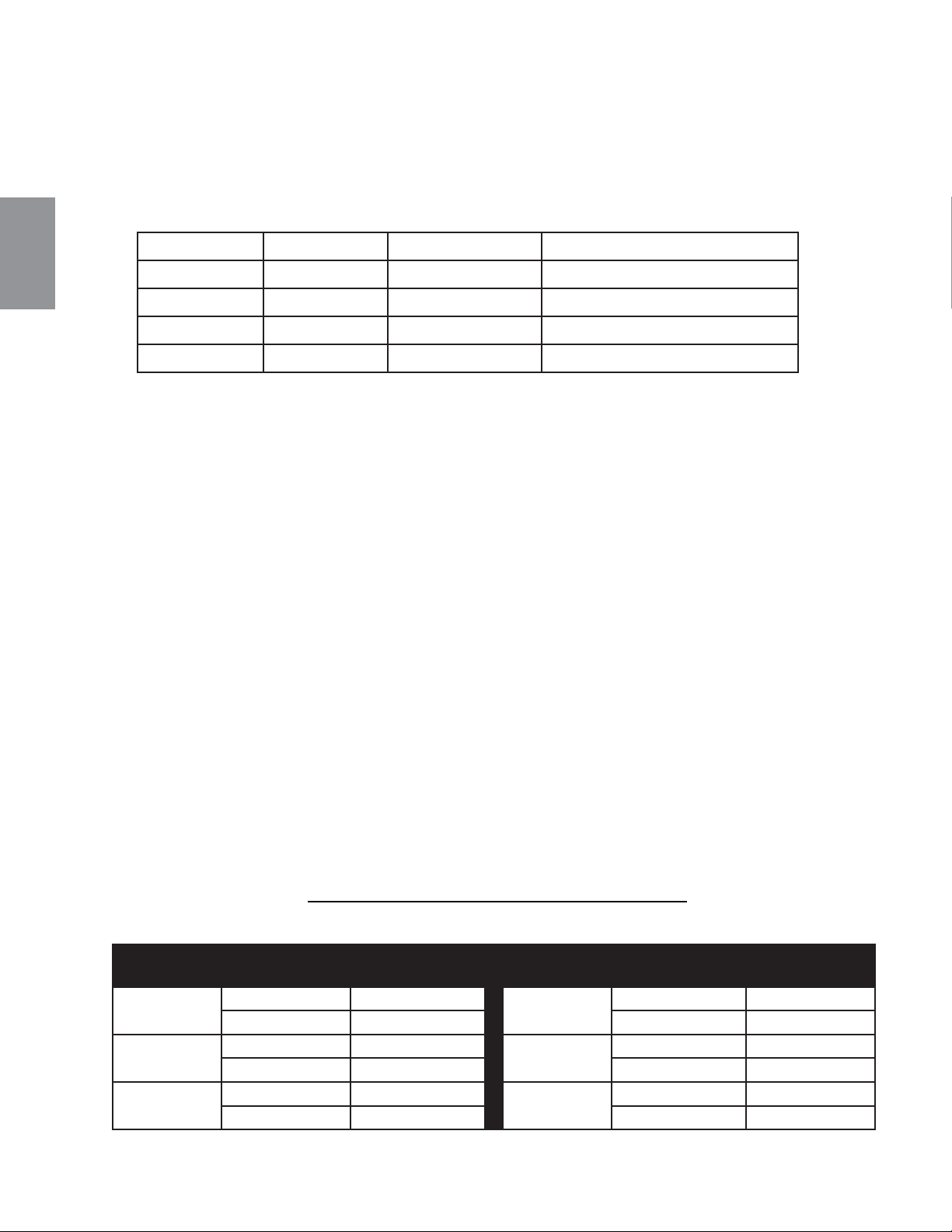
Utilisez uniquement des composants d’évacuation Wolf Steel, Simpson Dura-Vent, Selkirk Direct Temp, American
Metal Amerivent ou Metal-Fab. Les minimums et maximums des longueurs d’évent, pour les installations verticales et
horizontales, et les emplacements des terminaisons pour les deux systèmes sont précisés dans ce manuel et doivent
être respectés. Pour le Simpson Duravent, le Selkirk Direct Temp, l’American Metal Amerivent et le Metal-Fab, suivez la
procédure d’installation fournie avec les composants d’évacuation.
Un adaptateur de départ est nécessaire et peut être acheté chez le fournisseur correspondant :
Pour le Simpson Dura-Vent, le Selkirk Direct Temp, l’American Metal Amerivent et le Metal-Fab, suivez la
procédure d’installation qui se trouve sur le site Web de votre fournisseur.
Pour les systèmes d’évents dont le conduit intérieur d’évacuation possède déjà des joints scellés, seuls les joints du
conduit extérieur de prise d’air doivent être scellés avec un scellant de silicone rouge à haute température (RTV). Ce
même scellant peut être utilisé sur les joints des conduits intérieurs et extérieurs de tous les autres systèmes d’évents
approuvés à l’exception du raccordement du conduit d’évacuation à la buse du foyer qui doit être scellé avec le scellant
noir à haute température Mill Pac. Le scellant à haute température doit être commandé séparément.
Lorsque vous utilisez des composants d’évacuation Napoléon®, n’utilisez que des composants fl exibles/rigides
d’évacuation Wolf Steel ltée conjointement avec les ensembles de terminaison suivants : les ensembles de terminaison
murale GD222, GD222R, ou l’ensemble de terminaison pour toit de pente 1/12 à 7/12 GD110, l’ensemble de terminaison
pour toit de pente 8/12 à 12/12 GD111, l’ensemble de terminaison pour toit plat GD112 ou l’ensemble périscopique GD201
(pour pénétration des murs sous le niveau du sol). Lorsque vous utilisez des conduits fl exibles, conjointement avec les
différentes terminaisons, utilisez l’ensemble d’évents de 5PI (1,5m) GD220 ou l’ensemble d’évents de 10PI (3,1m) GD330.
Pour une performance optimale de l’appareil et une apparence optimale des fl ammes, gardez la longueur des
évents et le nombre de coudes au minimum. La prise d’air de la terminaison extérieure doit demeurer dégagée
en tout temps. Vérifi ez la prise d’air de la terminaison au moins une fois l’an pour vous assurer qu’elle n’est
pas obstruée ni endommagée.
Ne combinez pas de composants rigides ou fl exibles ni de composants d’évacuation provenant de fabricants
différents.
Ces ensembles d’évents permettent soit une évacuation verticale, soit une évacuation horizontale de l’appareil. La
course horizontale doit être conservée à un maximum de 20PI (6,1m). La hauteur totale permise pour un évent vertical
est de 40PI (12,2m). Lorsque vous utilisez des composants fl exibles, le nombre maximal de raccordements est de deux
horizontalement ou trois verticalement (excluant les raccordements à l’appareil et à la section de terminaison).
PIÈCE 4”/7” FOURNISSEUR SITE WEB
Duravent W175-0053 Wolf Steel www.duravent.com
Amerivent 4DSC-N2 American Metal www.americanmetalproducts.com
Direct Temp 4DT-AAN Selkirk www.selkirkcorp.com
SuperSeal 4DNA Metal-Fab www.mtlfab.com
8.1A
** Lorsqu'une course verticale est utilisée dans la confi guration d'évacuation, une pente de 0" par pied est
acceptable.
Pour une performance optimale, toutes les courses horizontales devraient avoir une élévation de 1" par pied.
PENTE REQUISE POUR L'ÉVACUATION
HORIZONTALE DU B36
PENTE REQUISE POUR L'ÉVACUATION
HORIZONTALE DU GX36
Évacuation
arrière
Évents rigides 1" /PI ** Évacuation
arrière
Évents rigides 0" /PI
Évents fl exibles 1" /PI ** Évents fl exibles 0" /PI
Évacuation
sur dessus
Évents rigides 0" /PI Évacuation
sur dessus
Évents rigides 0" /PI
Évents fl exibles 0" /PI Évents fl exibles 0" /PI
Évacuation
en coin
Évents rigides 6" (152mm) Évacuation
en coin
Évents rigides 0"
Évents fl exibles 6" (152mm) Évents fl exibles 6" (152mm)
90
W415-1401 / C / 03.19.15
FR
3.1 LONGUEURS DES CONDUITS D’ÉVACUATION ET COMPOSANTS
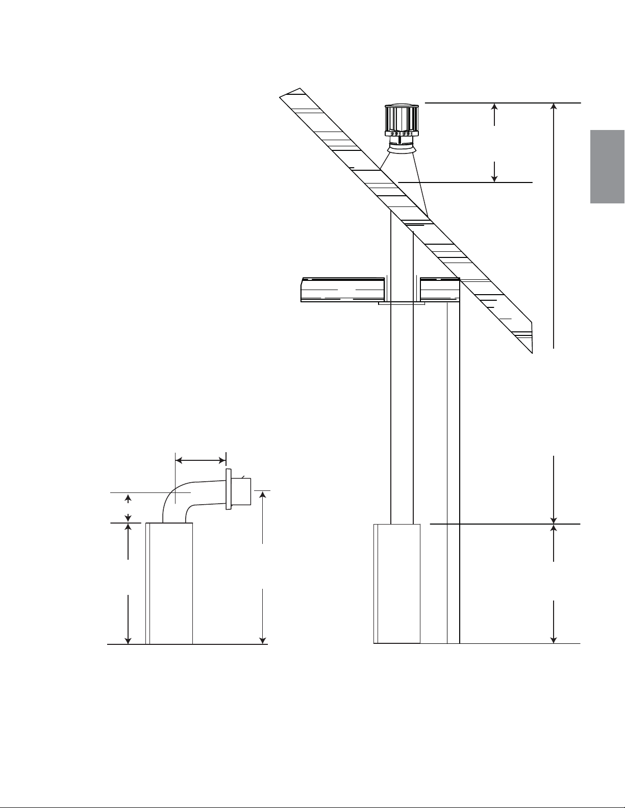
91
W415-1401 / C / 03.19.15
FR
3.2 INSTALLATIONS TYPIQUES D'ÉVENTS
ÉVACUATION SUR
LE DESSUS
16" (406MM)
MINIMUM
40 FT (12M)
MAXIMUM
3 FT (1M)
MINIMUM
34 1/16"
(865MM)
42 1/16" (1068MM)
MINIMUM PLUS LA
PENTE*
8" (203MM)
MINIMUM
34 1/16"
(865MM)
24" (610MM)
MAXIMUM
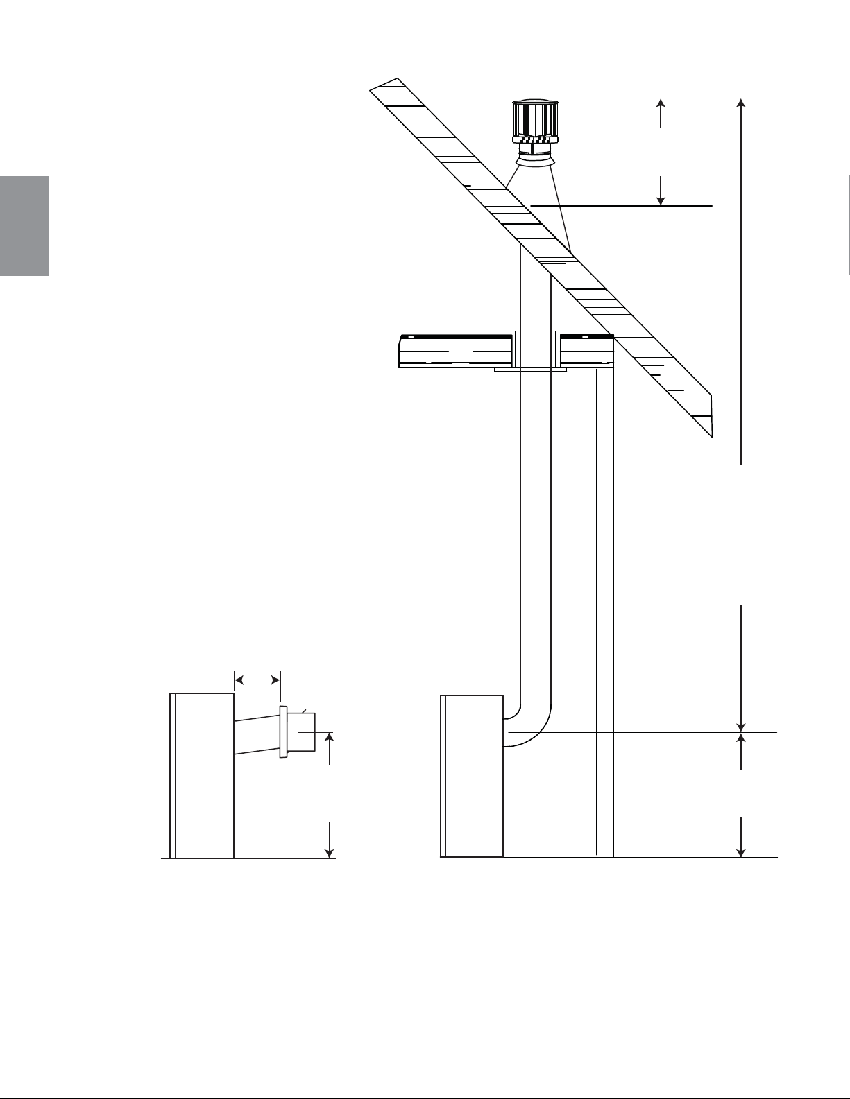
92
W415-1401 / C / 03.19.15
FR
40 FT (12M)
MAXIMUM
3 FT (1M)
MINIMUM
24"
(610MM)
16" (406MM)
MINIMUM
20"
(508MM)
MAX
24"
(610MM)
PLUS LA PENTE
ÉVACUATION SUR
L’ARRIÈRE
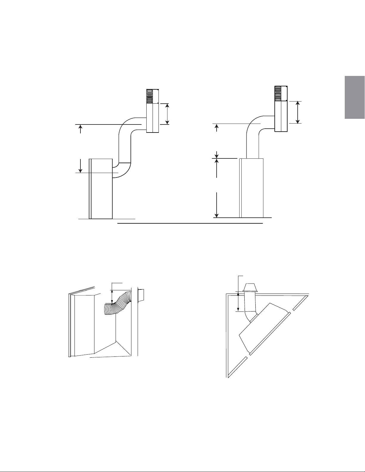
Utilisez l’ensemble périscopique afi n de positionner la terminaison au-dessus du niveau du sol. L’ensemble
périscopique doit être installé de façon à ce que la fente d’air du bas soit située à un minimum de 12 pouces
(304,8mm) au-dessus du niveau du sol. La longueur maximale permise de l’évent est de 10 pieds (3,1m)
pour un foyer et 8 pieds (2,4m) pour un poêle.
9.4A
12" (305MM)
MINIMUM
AU NIVEAU
DU SOL
12" (305MM)
MINIMUM
TO GRADE
30" (762MM)
MINIMUM
30" (762MM)
MINIMUM
34 1/16"
(865MM)
93
W415-1401 / C / 03.19.15
FR
Lorsque l’évent est installé en coin, la longueur maximale du conduit d’évacuation est de 20" (508mm) de
course horizontale, en plus de la déviation de 45°. Dans ce cas, une pente de zéro pouce est acceptable.
Cependant, il est conseillé de conserver une pente ascendante de 6"(152mm). Voir les illustrations ci-dessous:
20” (508mm)
MAXIMUM
6" (152mm) MINIMUM
D’ÉLÉVATION
3.3 INSTALLATIONS PARTICULIÈRES D'ÉVENTS
3.3.1 ENSEMBLE PÉRISCOPIQUE
3.3.2 INSTALLATION EN COIN
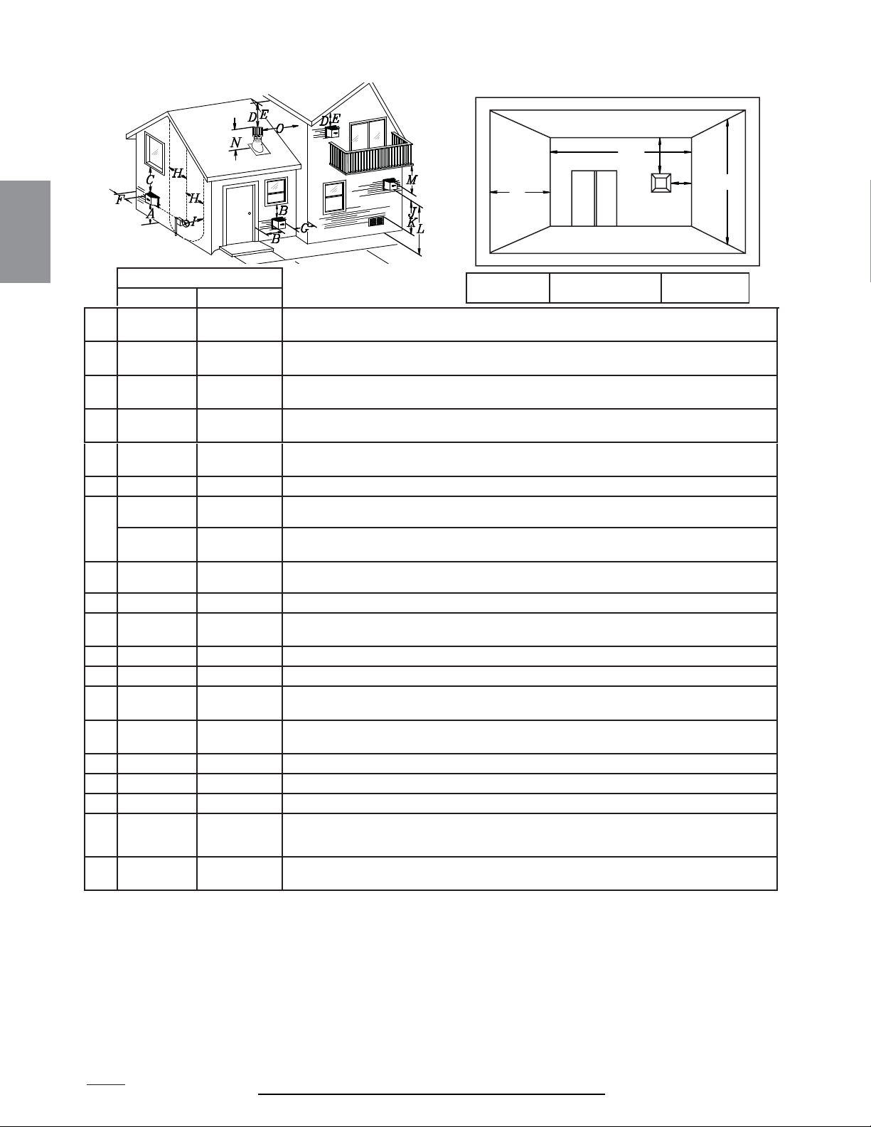
12.1D
INSTALLATION
CANADA É.-U.
A
12”
(304,8mm)
12”
(304,8mm)
Dégagement au-dessus du sol, d’une véranda, d’une terrasse en bois ou d’un balcon.
B
12”
(304,8mm)
Δ
9” (228,6mm)
Δ
Dégagement des fenêtres ou des portes qui ouvrent.
C
12”
(304,8mm)*
12”
(304,8mm)*
Dégagement des fenêtres fermées en permanence.
D
18”
(457,2mm)**
18”
(457,2mm)**
Dégagement vertical d’un soffi te ventilé situé au-dessus de la terminaison si la distance
horizontale est de moins de 2’ (0,6m) de la ligne médiane de la terminaison.
E
12”
(304,8mm)**
12”
(304,8mm)**
Dégagement d’un soffi te non ventilé.
F 0” (0mm) 0” (0mm) Dégagement des murs faisant coin extérieur.
G
0” (0mm)*** 0” (0mm)***
Dégagement des murs extérieurs incombustibles faisant coin intérieur ou aux obstructions
incombustibles (cheminée, etc.).
2”
(50,8mm)***
2”
(50,8mm)***
Dégagement des murs extérieurs combustibles faisant coin intérieur ou aux obstructions
combustibles (habillage extérieur, etc.).
H 3’ (0,9m) 3’ (0,9m)****
Dégagement horizontal de chaque côté depuis la ligne verticale tirée du centre d’un ensemble
de régulateur/compteur pour une distance verticale maximale de 15’ (4,6m).
I 3’ (0,9m) 3’ (0,9m)**** Dégagement de l’évent du régulateur.
J
12”
(304,8mm)
9” (228,6mm)
Dégagement d’une prise d’air de ventilation non mécanique de la maison ou d’une prise d’air de
combustion de tout autre appareil.
K 6’ (1,8m) 3’ (0,9m) † Dégagement d’une prise d’air mécanique.
L 7’ (2,1m) ‡ 7’ (2,1m) **** Dégagement au-dessus d’un trottoir ou d’une entrée pavée situés sur une propriété publique.
M
12”
(304,8mm)††
12”
(304,8mm)****
Dégagement sous une véranda ou une terrasse en bois.
N
16”
(406,4mm)
16”
(406,4mm)
Dégagement au-dessus du toit.
O 2’ (0,6m) †* 2’ (0,6m) †* Dégagement des murs adjacents, incluant les maisons voisines.
P 8’ (2,4m) 8’ (2,4m) Le toit doit être incombustible et sans ouvertures.
Q 3’ (0,9m) 3’ (0,9m)
Voir le tableau pour les dimensions d’un mur plus large
R 6’ (1,8m) 6’ (1,8m)
Voir le tableau pour les dimensions d’un mur plus profond. La terminaison ne doit pas être
installée sur quelconque mur ayant une ouverture entre la terminaison et le côté ouvert de la
structure.
S
12”
(304,8mm)
12”
(304,8mm)
Dégagement sous un balcon couvert.
Δ
Pour les structures comportant trois murs et un toit, la terminaison doit être située à plus de 6 pieds (1,8m) sous une fenêtre s’ouvrant sur un plan horizontal.
* Recommandé afi n de prévenir la formation de buée dans les fenêtres et les cassures thermiques.
** Il est recommandé d’utiliser un protecteur de chaleur et de maximiser la distance au soffi te de plastique.
*** L’ensemble périscopique requiert un dégagement minimal de 18 pouces (457,2m) d’un mur extérieur faisant coin intérieur.
**** Ceci est une distance recommandée. Vérifi ez les codes locaux pour connaître les contraintes additionnelles.
† Trois pieds au-dessus si la distance horizontale est de moins de 10 pieds (3,1m).
‡
Une terminaison d’évacuation ne doit pas être installée à un endroit où elle pourrait causer une formation dangereuse de givre ou de glace sur les surfaces d’une propriété
adjacente.
†† Permis seulement si la véranda ou la terrasse en bois sont complètement ouverts sur un minimum de deux côtés sous le plancher.
†* Recommandé afi n d’éviter la recirculation des produits d’échappement. Vérifi ez les codes locaux pour connaître les contraintes additionnelles.
††* Permis seulement si le balcon est complètement ouvert sur au moins un côté.
NOTE : Les dégagements sont en conformité avec les codes d’installation locaux et les exigences du fournisseur de gaz.
APPLICATIONS POUR BALCON COUVERT ††*
Q
MIN
R
MAX
MAX
R
= 3 pieds
(0,9m)
= 2 x
SLHGV
(4,6m)
Q
RÉELLE
R
Q
S
G
P
94
W415-1401 / C / 03.19.15
FR
3.4 EMPLACEMENTS ET DÉGAGEMENTS MINIMAUX DE LA TERMINAISON
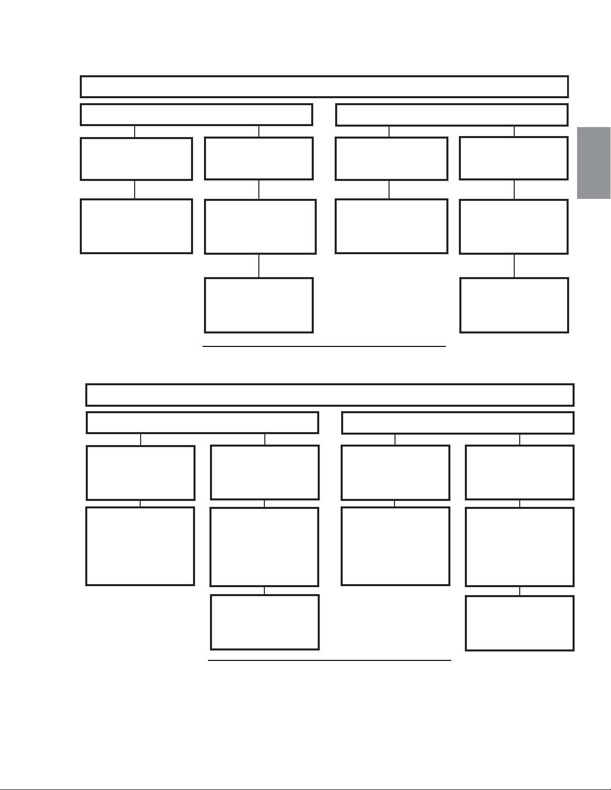
13.3A
ÉVACUATION SUR LE DESSUS
Terminaison horizontale
Terminaison verticale
La course verticale est
plus grande ou égale à
la course horizontale.
La course verticale
est plus petite que la
course horizontale.
La course verticale est
plus grande ou égale à
la course horizontale.
La course verticale
est plus petite que la
course horizontale.
La course horizontale
+ la course verticale
jusqu’à un maximum de
35’ (10,7m).
La course horizontale
+ la course verticale
jusqu’à un maximum
de 24,75’ (7,5m).
La course horizontale
+ la course verticale
jusqu’à un maximum de
35’ (10,7m).
La course horizontale
+ la course verticale
jusqu’à un maximum
de 35’ (10,7m).
4,2 fois la course
verticale plus grande
ou égale à la course
horizontale
3 fois la course
verticale plus grande
ou égale à la course
horizontale.
95
W415-1401 / C / 03.19.15
FR
3.5 CHARTE D'APPLICATION DES ÉVACUATIONS
13.2A
ÉVACUATION À L’ARRIÈRE
Terminaison horizontale
Terminaison verticale
La course verticale
est plus grande ou
égale à la course
horizontale
La course verticale
est plus petite
que la course
horizontale
La course verticale
est plus grande ou
égale à la course
horizontale
La course verticale
est plus petite
que la course
horizontale
La course
horizontale + la
course verticale
jusqu’à un
maximum de
40 pieds (12,2m)
La course
horizontale + la
course verticale
jusqu’à un
maximum de
24,75 pieds (7,5m)
La course
horizontale + la
course verticale
jusqu’à un
maximum de
40 pieds (12,2m)
La course
horizontale + la
course verticale
jusqu’à un
maximum de
40 pieds (12,2m)
3,5 fois la course
verticale plus
grande ou égale à la
course horizontale
3 fois la course
verticale plus
grande ou égale à la
course horizontale

14.1
Les symboles suivants sont utilisés dans le calcul et les exemples d’évacuation :
> - plus grand que
> - plus grand ou égal à
< - plus petit que
< - plus petit ou égal à
H
T
- total de la longueur des courses horizontales (Hr) et des déviations (Ho) en pieds
H
R
- longueur des courses horizontales combinées en pieds
H
O
- facteur de la valeur d’une déviation : 0,03 (du total des degrés de déviation - 90°*) en pieds
V
T
- longueur des courses verticales combinées en pieds
15.1A
PIEDS POUCES MILLIMÈTRES
1° 0,03 0,5 12,7
15° 0,45 6,0 152,4
30° 0,9 11,0 279,4
45° 1,35 16,0 406,4
90°* 2,7 32,0 812,8
* La première déviation de 90° a une valeur zéro et est illustrée dans la formule comme - 90°
96
W415-1401 / C / 03.19.15
FR
3.6 LÉGENDE
3.7 VALEURS DU COUDE EN LONGUEURS D'ÉVENT
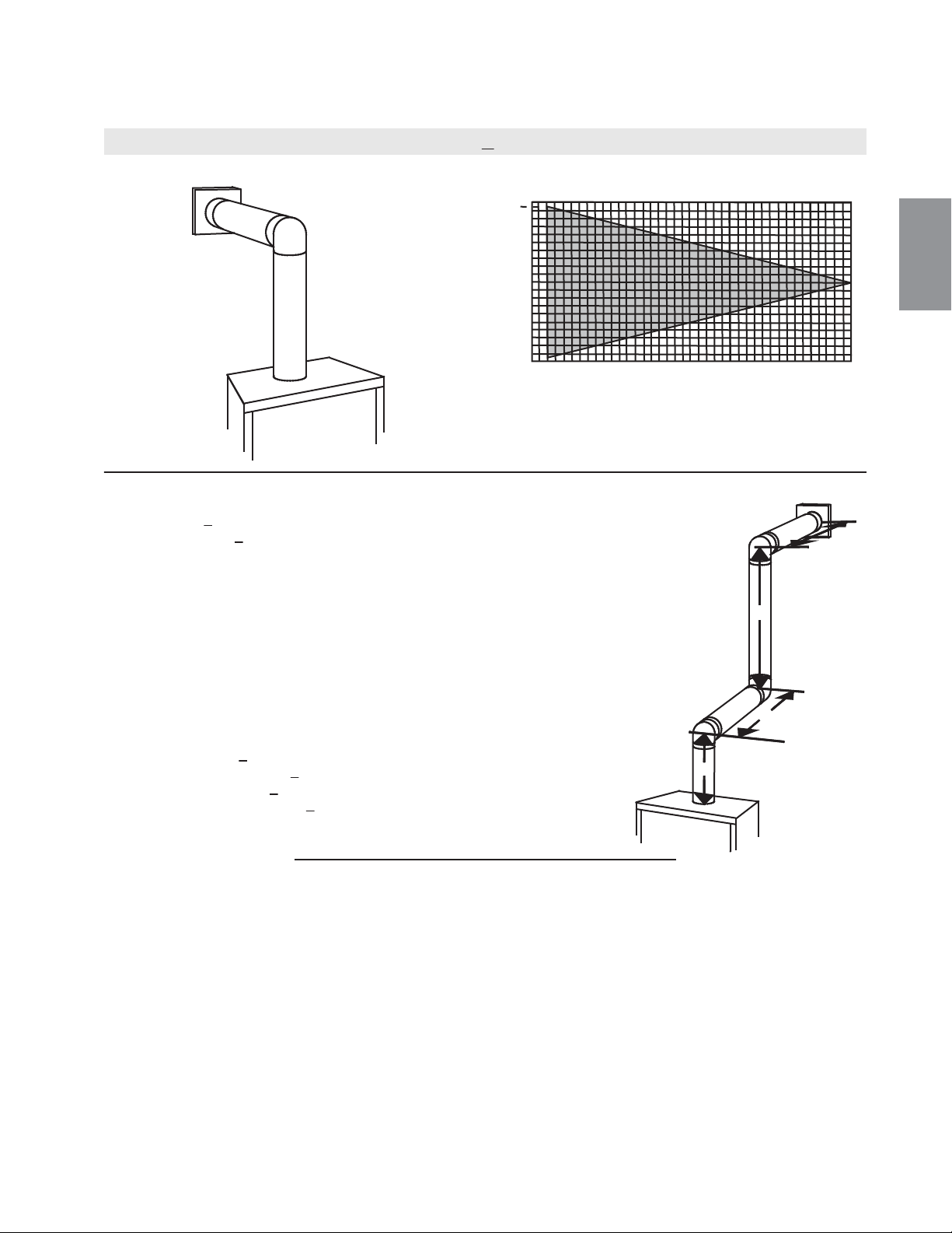
97
W415-1401 / C / 03.19.15
FR
3.8 ÉVACUATION SUR LE DESSUS TERMINAISON HORIZONTAL
(H
T
) < (V
T
)
Configuration d'évacuation simple (un coude de 90°
seulement).
Consultez le graphique pour déterminer la course verticale
nécessaire V
T
par rapport à la course horizontale requise H
T
.
0
2.5
(0,8)
5
(1,5)
7.5
(2,3)
10
(3,1)
12.5
(3,8)
15
(4,6)
40 (12,2)
10 (3,1)
20 (6,1)
30 (9,1)
17.5
(5,3)
20
(6,1)
39 (11,9)
COURSE
VERTICALE
REQUISE EN
PIEDS
(MÈTRES) V
T
LONGUEUR DES COURSES HORIZONTALES PLUS
LES DÉVIATIONS EN PIEDS (MÈTRES) H
T
Lorsque la configuration de l'évacuation exige plus d'un coude de 90°, les formules suivantes s'appliquent :
Formule 1 : H
T
< V
T
Formule 2 : H
T
+ V
T
< 40 pieds (12,2m)
Exemple :
V
1
= 3 PI (0,9m)
V
2
= 8 PI (2,4m)
V
T
= V
1
+ V
2
= 3PI (0,9m) + 8PI (2,4m) = 11PI (3,4m)
H
1
= 2,5 PI (0,8m)
H
2
= 2 PI (0,6m)
H
R
= H
1
+ H
2
= 2,5PI (0,8m) + 2PI (0,6m) = 4,5 PI (1,4m)
H
O
= 0,03 (trois coudes 90° - 90°) = 0,03 (270° - 90°) = 5,4 PI (1,6m)
H
T
= H
R
+ H
O
= 4,5PI (1,4m) + 5,4PI (1,6m) = 9,9 PI (3m)
H
T
+ V
T
= 9,9PI (3m) + 11PI (3,4m) = 20,9 PI (6,4m)
Formule 1 : H
T
< V
T
9,9PI (3m) < 11PI (3,4m)
Formule 2 : H
T
+ V
T
< 40 PI (12,2m)
20,9PI (6,4m) < 40 PI (12,2m)
Puisque les deux formules sont respectées, cette configuration
d'évacuation est acceptable.
90°
90°
90°
V
1
V
2
H
1
H
2
La section ombragée à l'intérieur des lignes représente
des valeurs acceptables pour H
T
et V
T
.
16.1B
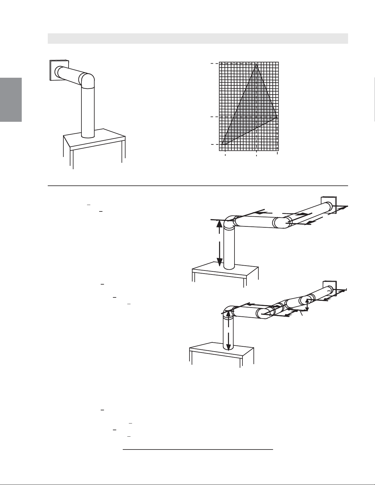
98
W415-1401 / C / 03.19.15
FR
(H
T
) > (V
T
)
Configuration d'évacuation simple
(un coude de 90° seulement)
Consultez le graphique pour déterminer la course verticale nécessaire V
T
par rapport à la course horizontale requise H
T
.
LONGUEUR DES COURSES HORIZONTALES PLUS LES DÉVIATIONS EN
PIEDS (MÈTRES)H
T
Lorsque la configuration de l'évacuation exige plus qu'un coude de 90°, les formules suivantes s'appliquent :
Formule 1 : H
T
< 4,2 V
T
Formule 2 : H
T
+ V
T
< 24,75 pieds (7,5m)
Exemple :
V
1
= V
T
= 6 PI (1,8m)
H
1
= 3 PI (0,9m)
H
2
= 5 PI (1,5m)
H
R
= H
1
+ H
2
= 3PI (0,9m) + 5PI (1,5m) = 8 PI (2,4m)
H
O
= 0,03 (deux coudes 90° - 90°) = 0,03 (180° - 90°) = 2,7PI (0,8m)
H
T
= H
R
+ H
O
= 8 PI (2,4m) + 2,7 PI (0,8m) = 10,7 PI (3,3m)
H
T
+ V
T
= 10,7 PI (3,3m) + 6PI (1,8m) = 16,7 PI (5,1m)
Formule 1 : H
T
< 4,2 V
T
4,2 V
T
= 4,2PI (1,3m) x 6PI (1,8m) = 25,2 PI (7,7m)
Formule 2 : H
T
+ V
T
< 24,75 PI (7,5m)
16,7PI (5,1m) < 24,75 PI (7,5m)
Puisque les deux formules sont respectées, cette configuration
d'évacuation est acceptable.
La section ombragée à l'intérieur des lignes représente des valeurs acceptables pour H
T
et V
T
90°
V
1
H
1
H
2
90°
Exemple :
V
1
= 4 PI (1,2m)
V
2
= 1,5 PI (0,5m)
V
T
= V
1
+ V
2
= 4PI (1,2m) + 1,5PI (0,5m) = 5,5 PI (1,7m)
H
1
= 2 PI (0,6m)
H
2
= 1 PI (0,3m)
H
3
= 1 PI (0,3m)
H
4
= 1,5 PI (0,5m)
H
R
= H
1
+ H
2
+ H
3
+ H
4
= 2 PI (0,6m) + 1 PI (0,3m) + 1 PI (0,3m) + 1,5 PI (0,5m) = 5,5 PI (1,7m)
H
O
= 0,03 (quatre coudes 90° - 90°) = 0,03 (360° - 90°) = 8,1 PI (2,5m)
H
T
= H
R
+ H
O
= 5,5 PI (1,7m) + 8,1 PI (2,5m) = 13,6 PI (4,2m)
H
T
+ V
T
= 13,6 PI (4,2m) + 5,5 PI (1,7m) = 19,1 PI (5,8m)
Formule 1 : H
T
< 4,2 V
T
4,2 V
T
= 4,2 PI (1,3m) x 5,5 PI (1,7m) = 23,1 PI (7m)
13,6 PI (4,2m) < 23,1 PI (7m)
Formule 2 : H
T
+ V
T
< 24,75 PI (7,5m)
19,1PI (5,8m) < 24,75 PI (7,5m)
Puisque les deux formules sont respectées, cette configuration d'évacuation est acceptable.
90°
90°
90°
90°
H
1
H
2
V
1
V
2
H
3
H
4
0
10 (254)
5
(1,5)
15
(4,6)
20 (6,1)
12,5
(3,8)
2
(0,6)
10
(3,1)
19,5
(5,9)
100 (2540)
50 (1270)
150 (3810)
57 (1447,8)
147 (3733,8)
COURSE
VERTICALE
REQUISE EN
POUCES
(MILLMÈTRES)V
T
16.2
_
3B
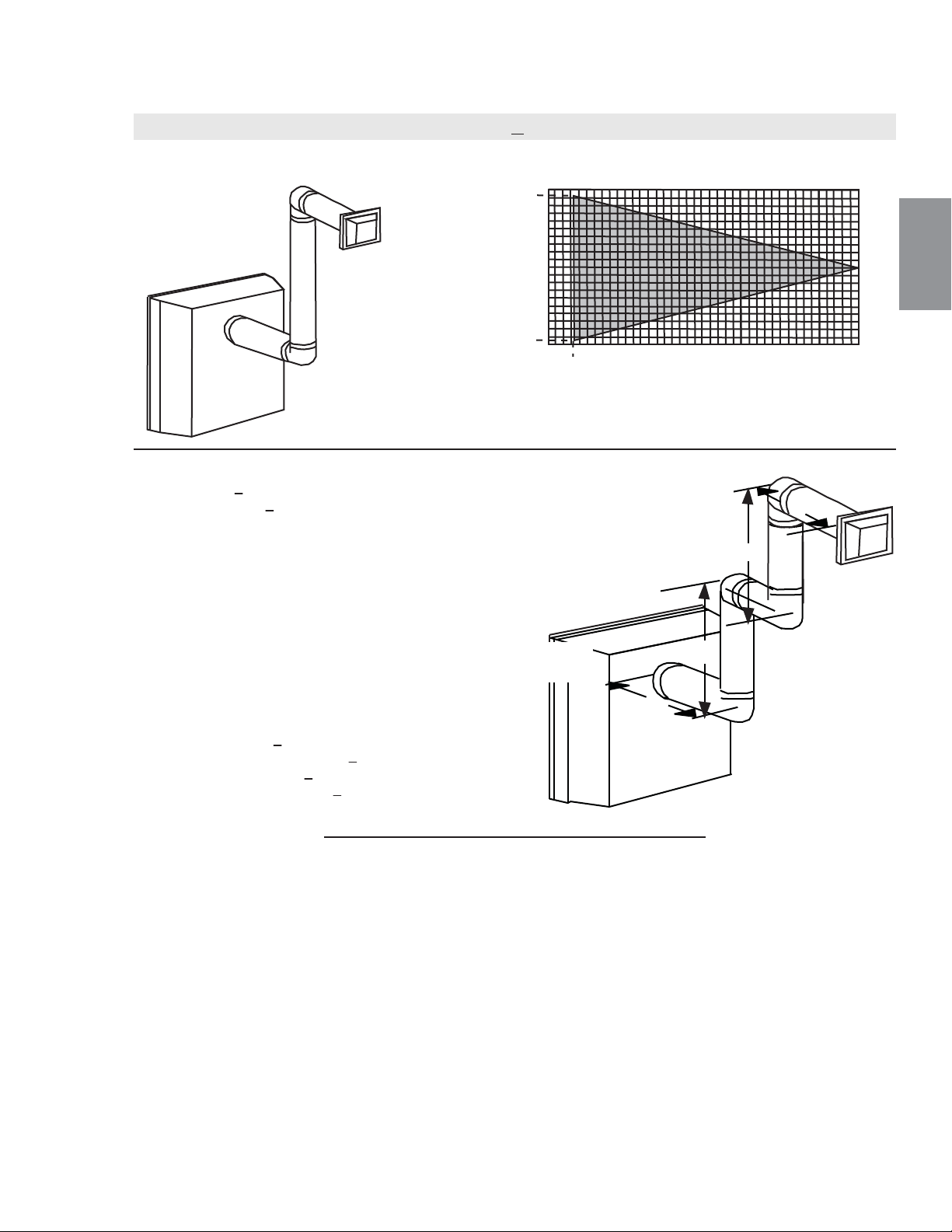
3.9 ÉVACUATION À L'ARRIÈRE TERMINAISON HORIZONTALE
0
2,5
(0,8)
5
(1,5)
7,5
(2,3)
10
(3,1)
12,5
(3,8)
15
(4,6)
40 (12,2)
10 (3,1)
20 (6,1)
30 (9,1)
17,5
(5,3)
20
(6,1)
1,6
(0,5)
1,6 (0,5)
38,3 (11,7)
90°
V
1
V
2
H
1
H
2
90°
90°
90°
H
3
Configuration d'évacuation simple
(deux coudes de 90° seulement)
Consultez le graphique pour déterminer la course verticale nécessaire
V
T
par rapport à la course horizontale requise H
T
.
COURSE
VERTICALE
REQUISE
EN PIEDS
(MÈTRES)V
T
LONGUEUR DES COURSES HORIZONTALES PLUS
LES DÉVIATIONS EN PIEDS (MÈTRES) H
T
La section ombragée à l'intérieur des lignes représente des valeurs
acceptables pour H
T
et V
T
(H
T
) < (V
T
)
16.3A
Lorsque la configuration de l'évacuation exige plus qu'un coude de 90°, les formules suivantess'appliquent :
Formule 1: H
T
< V
T
Formule 2: H
T
+ V
T
< 40 pieds (12,2m)
Exemple:
V
1
= 9 PI (2,7m)
V
2
= 6 PI (1,8m)
V
T
= V
1
+ V
2
= 9 PI (2,7m) + 6 PI (1,8m) = 15 PI (4,6m)
H
1
= 3 PI (0,9m)
H
2
= 2 PI (0,6m)
H
3
= 1,5 PI (0,5m)
H
R
= H
1
+ H
2
+ H
3
= 3PI (0,9m) + 2PI (0,6m) + 1.5PI (0,5m) = 6.5PI (2m)
H
O
= 0,03 (quatre coudes 90° - 90°) = 0,03 (360° - 90°) = 8,1 PI (2,5m)
H
T
= H
R
+ H
O
= 6,5PI (2m) + 8,1PI (2,5m) = 14,6PI (4,5m)
H
T
+ V
T
= 14,6PI (4,5m) + 15PI (4,6m) = 29,6PI (9m)
Formule 1: H
T
< V
T
14,6 PI (4,5m) < 15 PI (4,6m)
Formule 2: H
T
+ V
T
< 40 PI (12,2m)
29,6PI (9m) < 40PI (12,2m)
Puisque les deux formules sont respectées, cette configuration d’évacuation est acceptable.
99
W415-1401 / C / 03.19.15
FR
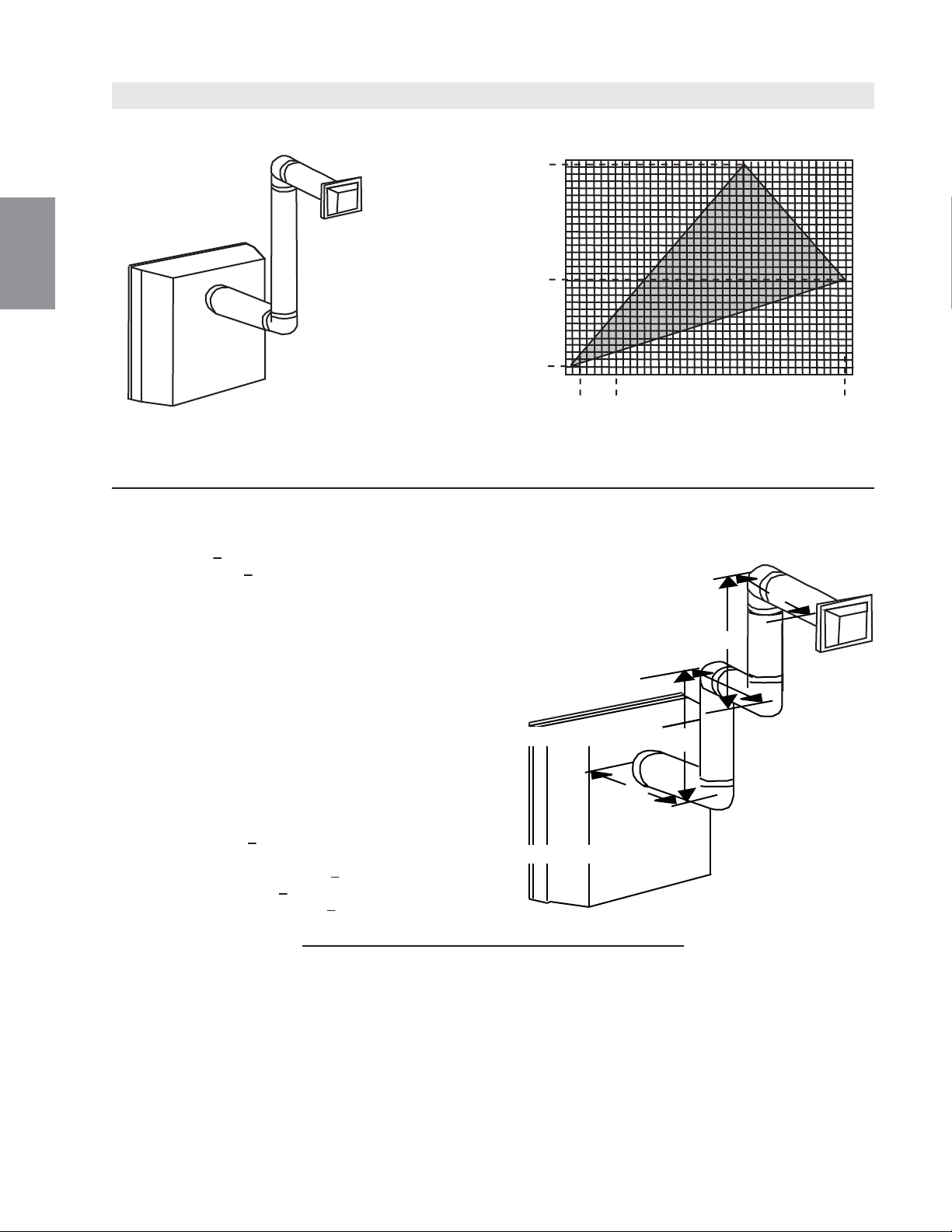
Configuration d'évacuation simple
(deux coudes de 90° seulement)
Consultez le graphique pour déterminer la course verticale
nécessaire V
T
par rapport à la course horizontale requise H
T
.
COURSE
VERTICALE
REQUISE
EN PIEDS
(MÈTRES) V
T
LONGUEUR DES COURSES HORIZONTALES PLUS
LES DÉVIATIONS EN PIEDS (MÈTRES) H
T
La section ombragée à l'intérieur des lignes représente
des valeurs acceptables pour H
T
et V
T
90°
V
1
V
2
H
1
H
2
90°
90°
90°
H
3
(H
T
) > (V
T
)
16.3_2B
50 (1270)
100 (2540)
150(3810)
0
2,5
(0,8)
5
(1,5)
7,5
(2,3)
10
(3,1)
12,5
(3,8)
15
(4,6)
17,5
(5,3)
20
(6,1)
147 (3733,8)
12 (304,8)
66
(1676,4)
1
(0,3)
3,5
(1,1)
19,25
(5,9)
Lorsque la configuration de l'évacuation exige plus qu'un coude de 90°, les formules suivantes
s'appliquent :
Formule 1 : H
T
< 3,5V
T
Formule 2 : H
T
+ V
T
< 24,75 pieds (7,5m)
Exemple :
V
1
= 4 PI (1,2m)
V
2
= 1,5 PI (0,5m)
V
T
= V
1
+ V
2
= 4PI (1,2m) + 1,5PI (0,5m) = 5,5 PI (1,7m)
H
1
= 2 PI (0,6m)
H
2
= 1 PI (0,3m)
H
3
= 1 PI (0,3m)
H
4
= 1,5 PI (0,5m)
H
R
= H
1
+ H
2
+ H
3
+ H
4
= 2PI(0,6m) + 1PI(0,3m) + 1PI(0,3m) + 1,5PI(0,5m) = 5,5PI(1,7m)
H
O
= 0,03 (quatre coudes 90° + un coude 45° - 90°)
= 0,03 (90 + 90 + 90 + 90 + 45 - 90) = 9,45 PI (2,9m)
H
T
= H
R
+ H
O
= 5,5PI (1,7m) + 9,45PI (2,9m) = 14,95PI (4,6m)
H
T
+ V
T
= 14,95PI (4,6m) + 5,5PI (1,7m) = 20,45PI (6,2m)
Formule 1 : H
T
< 3,5V
T
3,5V
T
= 3,5PI (1,1m) x 5,5PI (1,7m) = 19,25PI (5,9m)
14,95 PI (4,6m) < 19,25 PI (5,9m)
Formule 2 : H
T
+ V
T
< 24,75 PI (7,5m)
20,45 PI (6,2m) < 24,75 PI (7,5m)
Puisque les deux formules sont respectées, cette configuration d'évacuation est acceptable.
100
W415-1401 / C / 03.19.15
FR
50 (1270)
100 (2540)
150(3810)
0
2.5
(0.8)
5
(1.5)
7.5
(2.3)
10
(3.1)
12.5
(3.8)
15
(4.6)
17.5
(5.3)
20
(6.1)
147 (3733.8
8 (203)
66
(1676.4)
1
(0.3)
3.5
(1.1)
19.25
(5.9)
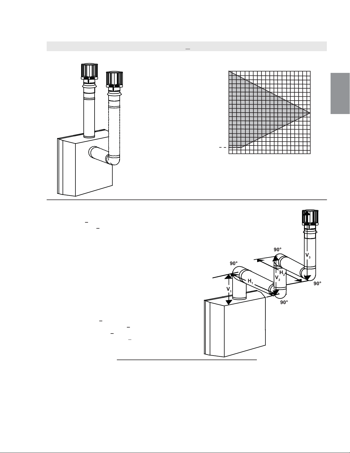
Configurations d'évacuation simples.
Consultez le graphique pour déterminer la course verticale
nécessaire V
T
par rapport à la course horizontale requise H
T
.
COURSE
VERTICALE
REQUISE EN
PIEDS
(MÈTRES) V
T
LONGUEUR DES COURSES HORIZONTALES PLUS
LES DÉVIATIONS EN PIEDS (MÈTRES) H
T
La section ombragée à l'intérieur des lignes représente
des valeurs acceptables pour H
T
et V
T
(H
T
) < (V
T
)
18.2A
Lorsque les configurations de l'évacuation exigent plus que zéro coude de 90° (évacuation sur le dessus) ou un
coude de 90° (évacuation à l'arrière), les formules suivantes s'appliquent :
Formule 1: H
T
< V
T
Formule 2: H
T
+ V
T
< 40 pieds (12,2m)
Exemple:
V
1
= 5 PI (1,5m)
V
2
= 6 PI (1,8m)
V
3
= 10 PI (3,1m)
V
T
= V
1
+ V
2
+ V
3
= 5PI (1,5m) + 6PI (1,8m) + 10PI (3,1m) = 21PI (6,4m)
H
1
= 8 PI (2,4m)
H
2
= 2,5 PI (0,8m)
H
R
= H
1
+ H
2
= 8PI (2,4m) + 2,5PI (0,8m) = 10,5PI (3,2m)
H
O
= 0,03 (quatre coudes 90°- 90°)
= 0,03 (360° - 90°) = 8,1 PI (2,5m)
H
T
= H
R
+ H
O
= 10,5PI (3,2m) + 8,1PI (2,5m) = 18,6PI (5,7m)
H
T
+ V
T
= 18,6PI (5,7m) + 21PI (6,4m) = 39,6PI (12,1m)
Formule 1: H
T
< 3,5V
T
18,6 PI (5,7m) < 21 PI (6,4m)
Formule 2: H
T
+ V
T
< 40 PI (12,2m)
39,6PI (12,1m) < 40 PI (12,2m)
Puisque les deux formules sont respectées, cette configuration
d’évacuation est acceptable
0
5
(1,5)
10
(3,1)
15
(4,6)
20
(6,1)
40 (12,2)
10 (3,1)
20 (6,1)
30 (9,1)
3 (0,9)
3.10 ÉVACUATION SUR LE DESSUS OU À L'ARRIÈRE TERMINAISON VERTICALE
101
W415-1401 / C / 03.19.15
FR
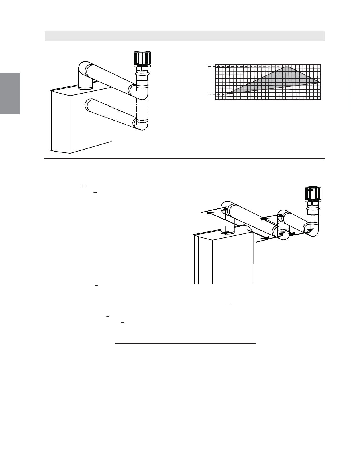
Configurations d'évacuation simples.
Consultez le graphique pour déterminer la course verticale
nécessaire V
T
par rapport à la course horizontale requise H
T
.
COURSE
VERTICALE
REQUISE EN
PIEDS
(MÈTRES) V
T
LONGUEUR DES COURSES HORIZONTALES PLUS
LES DÉVIATIONS EN PIEDS (MÈTRES) H
T
La section ombragée à l'intérieur des lignes représente
des valeurs acceptables pour H
T
et V
T
90°
V
1
H
1
H
2
90°
90°
90°
V
3
V
2
(H
T
) > (V
T
)
18.2_2B
0
5
(1,5)
10
(3,1)
15
(4,6)
20
(6,1)
10 (3,1)
20 (6,1)
3 (0,9)
25
(7,6)
30
(9,1)
19 (5,8)
Lorsque les configurations de l'évacuation exigent plus que zéro coude de 90° (évacuation sur le dessus) ou un
coude de 90° (évacuation à l'arrière), les formules suivantes s'appliquent :
Formule 1 : H
T
< 3 V
T
Formule 2 : H
T
+ V
T
< 40 pieds (12,2m)
Exemple :
V
1
= 2 PI (0,6m)
V
2
= 1 PI (0,3m)
V
3
= 1,5 PI (0,5m)
V
T
= V
1
+ V
2
+ V
3
= 2PI (0,6m) + 1PI (0,3m) + 1,5PI (0,5m) = 4,5PI (1,4m)
H
1
= 6 PI (1,8m)
H
2
= 2 PI (0,6m)
H
R
= H
1
+ H
2
= 6PI (1,8m) + 2PI (0,6m) = 8 PI (2,4m)
H
O
= 0,03 (quatre coudes 90° - 90°)
= 0,03 (360° - 90°) = 8,1 PI (2,5m)
H
T
= H
R
+ H
O
= 8PI (2,4m) + 8,1PI (2,5m) = 16,1 PI (4,9m)
H
T
+ V
T
= 16,1PI (4,9m) + 4,5PI (1,4m) = 20,6 PI (6,3m)
Formule 1 : H
T
< 3V
T
3V
T
= 3 PI (0,9m) x 4,5 PI (1,4m) = 13,5 PI (4,1m)
16,1PI (4,9m) > 13,5 PI (4,1m)
Puisque cette formule n'est pas respectée, cette configuration d'évacuation est inacceptable.
Formule 2 : H
T
+ V
T
< 40 PI (12,2m)
20,6 PI (4,9m) < 40 PI 12,2m)
Puisque seulement la formule 2 est respectée, cette configuration est inacceptable et l'on devra trouver un autre endroit
pour installer l’appareil ou trouver une configuration d'évacuation qui pourra respecter les deux formules.
102
W415-1401 / C / 03.19.15
FR
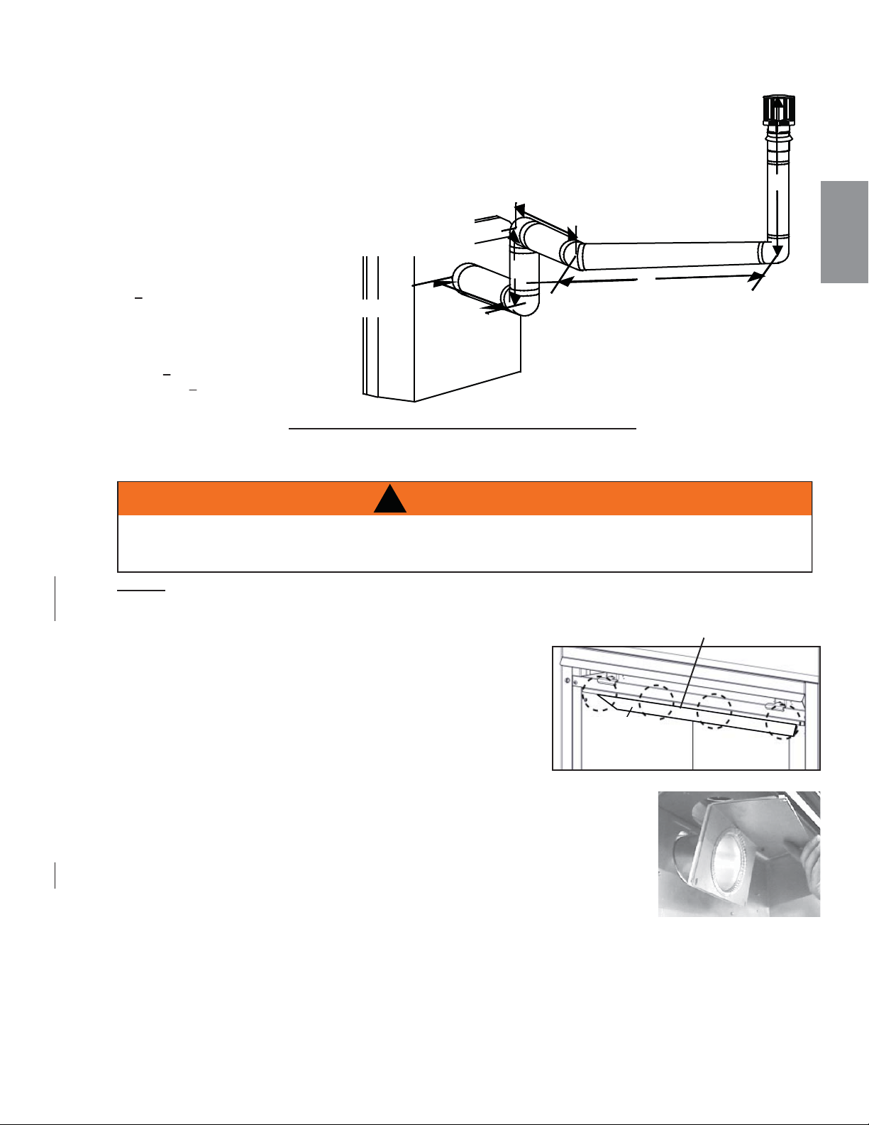
3.11 ÉVACUATION À L'ARRIÈRE
90°
V
1
V
2
H
1
H
2
90°
90°
H
3
45°
18.2_3A
Exemple :
V
1
= 1,5 PI (0,5m)
V
2
= 5 PI (1,5m)
V
T
= V
1
+ V
2
= 1,5PI (0,5m) + 5PI (1,5m) = 6,5 PI (2m)
H
1
= 1 PI (0,3m)
H
2
= 1 PI (0,3m)
H
3
= 10,75 PI (3,3m)
H
R
= H
1
+ H
2
+ H
3
= 1PI (0,3m) + 1PI (0,3m) + 10,75PI (3,3m) = 12,75PI (3,9m)
H
O
= 0,03 (quatre coudes 90° + un coude 45° - 90°)
= 0,03 (360° + 45° - 90°) = 6,75 PI (2,1m)
H
T
= H
R
+ H
O
= 12,75PI (3,9m) + 6,75PI (2,1m) = 19,5PI (5,9m)
H
T
+ V
T
= 19,5 PI (5,9m) + 6,5 PI (2m) = 26 PI (7,9m)
Formule 1 :
H
T
< 3 V
T
3 V
T
= 3PI (0,9m) x 6,5PI (2m) = 19,5PI (5,9m)
19,5 PI (5,9m) = 19,5 PI (5,9m)
Formule 2 :
H
T
+ V
T
< 40 PI (12,2m)
26 PI (7,9m) < 40 PI (12,2m)
Puisque les deux formules sont respectées, cette configuration d'évacuation est acceptable.
103
W415-1401 / C / 03.19.15
FR
!
AVERTISSEMENT
IL EST ESSENTIEL QUE LE COUVERCLE D'ÉVACUATION SOIT INSTALLÉ SINON L’APPAREIL NE
FONCTIONNERA PAS CORRECTEMENT ET POURRAIT CAUSER DES BLESSURES OU DES
DOMMAGES MATÉRIELS.
A. Enlevez l'écran de protection et vitre du porte, référer de la
section, "OUVERTURE ET FERMETURE DE LA PORTE ET
L'ÉCRAN DE PROTECTION".
B. Enlevez les contenu de l'intérieur de la chambre de
combustion, vous aurez besoin de la collet d'évacuation de
4" (102mm).
C. Retirez les quatre tête hexagonale de fi xation du défl ecteur
de l'intérieur de la partie supérieure avant de la chambre de
combustion, voir Figure 1.
D. Placez les joint d’étanchéité (fourni) au cours de l'assemblage du collet
d'évacuation de 4" (102mm) et plier le long de la perforation.
E. De l'intérieur de la chambre de combustion, insérez le collet d'évacuation
de 4" (102mm) /joint d'étanchéité à travers l'arrière de la chambre de
combustion. Fixez l’assemblage à l'arrière et dans le haut de l'appareil à
l'aide des quatre vis à tête 3/8" fi letage vis à tête, voir Figure 2. NOTE: Ne
serrez pas trop les vis. Il suffi t d'appuyer le joint d'étanchéité contre la
chambre de combustion.
F. Réinstallez la défl ecteur supérieur avec les 4 vis. Installez les ensemble des bûches, vitre du porte et
l'écran de protection.
Fig. 2
DEFLECTOR
Fig. 1
DEFLECTEUR
NOTE: Une #42 injecteur a été fourni avec votre appareil. Dans les installations avec un verticale aug-
menter supérieur à 8 "(203mm) dans la confi guration d'évacuation, le #42 injecteur doit être utilisé pour
augmenter la taille de la fl amme.
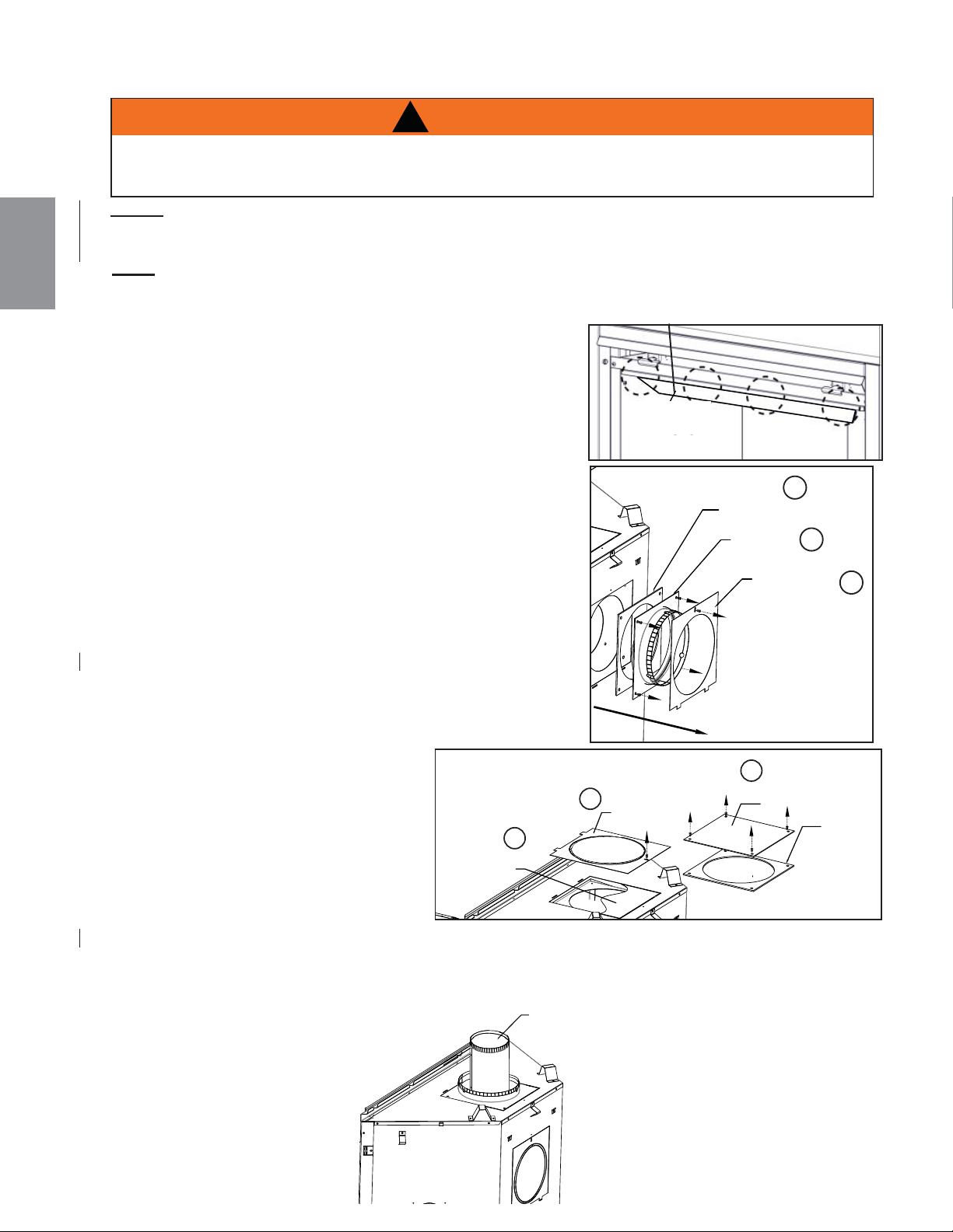
DEFLECTOR
104
W415-1401 / C / 03.19.15
FR
3.12 ÉVACUATION SUR LE DESSUS
A. Enlevez l'écran de protection et vitre du porte, référer de la section, "OUVERTURE ET FERMETURE
DE LA PORTE ET L'ÉCRAN DE PROTECTION".
B. Enlevez les contenu de l'intérieur de la chambre de
combustion, vous aurez besoin de la collet d'évacuation de
4" (102mm).
C. De l'intérieur de la chambre de combustion, enlevez les
défl ecteur supérieur.
D. Enlevez le une vis à parti de la couvercle d’extérieur de
l'arrière de la chambre de combustion.
E. Enlevez les 4 vis sur le collet d'évacuation de 7" (178mm);
mettre de côté le collet d'évacuation et le joint d’étanchéité.
Ne pas endommager le joint d’étanchéité.
F. Enlevez le une vis à parti de la couvercle d’extérieur avec
knockout, dans le haut de l'appariel et mettre de côté.
G. Enlevez la plaque de couverture intérieure et le joint
d’étanchéité par enlevez les 4 vis. Réinstaller la plaque de
couverture intérieure et joint d’étanchéité sur l’arrière de
l'appareil.
H. Fixez la couvercle d’extérieur avec knockout sur l’arrière de
l'appareil.
I. Retirez et jetez les épaisseur d'isolation 1 1/2".
J. Placez les le collet d'évacuation de
7" (178mm) et le joint d’étanchéité
dans le haut de l'appareil et fi xez
avec les 4 vis.
K. Réinstaller la couvercle d’extérieur
avec knockout sur la collet
d'évacuation 7" (178mm) et fi xez.
L. De l'intérieur de la chambre de
combustion, installez la collet
d'évacuation de 4" (102mm) à
travers la haut de la chambre de combustion et des quatre vis à tête 3/8". NOTE: Ne serrez pas
trop les vis. Il suffi t d'appuyer le joint d'étanchéité contre la chambre de combustion.
M. Réinstallez la défl ecteur supérieur avec les 4 vis. Installez les ensemble des bûches, vitre du porte
et l'écran de protection.
NOTE: Cet l'appareil a été livré comme un évent l'arrière.
EXHAUST FLUE COLLAR
COLLET
D’ÉVACUATION
JOINT
D’ÉTANCHÉITÉ
COUVERTURE
D’EXTÉRIEUR
D
E
E
COQUILLE
D’EXTÉRIEUR
COUVERCLE
F
F
COUVERCLE
D’EXTÉRIEUR
(avec couverture)
PLAQUE DE
RECOUVREMENT
INTÉRIEUR
G
JOINT
D’ÉTANCHÉITÉ
!
AVERTISSEMENT
IL EST ESSENTIEL QUE LE COUVERCLE D'ÉVACUATION SOIT INSTALLÉ SINON L’APPAREIL NE
FONCTIONNERA PAS CORRECTEMENT ET POURRAIT CAUSER DES BLESSURES OU DES
DOMMAGES MATÉRIELS.
DEFLECTEUR
COLLET D'ÉVACUATION
NOTE: Une #42 injecteur a été fourni avec votre appareil. Dans les installations avec un verticale aug-
menter supérieur à 8 "(203mm) dans la confi guration d'évacuation, le #42 injecteur doit être utilisé pour
augmenter la taille de la fl amme.
!
AVERTISSEMENT
AVANT D’EFFECTUER LES BRANCHEMENTS POUR L’ALIMENTATION EN GAZ ET ÉLECTRIQUE,
ASSUREZ-VOUS DE RETIRER TOUTE COMPOSANTE NON FIXÉE À L’INTÉRIEUR DE LA CHAMBRE
DE COMBUSTION.
SI VOTRE APPAREIL COMPREND UN SYSTÈME DE TÉLÉCOMMANDE, ASSUREZ-VOUS QUE LE
RÉCEPTEUR EST À LA POSITION « OFF » AVANT D’EFFECTUER LES BRANCHEMENTS POUR
L’ALIMENTATION EN GAZ ET ÉLECTRIQUE.
AFIN D’ASSURER UN FONCTIONNEMENT SÉCURITAIRE ET ADÉQUAT DE L’APPAREIL, VOUS DEVEZ
OBSERVER LES INSTRUCTIONS D’ÉVACUATION À LA LETTRE.
TOUS LES JOINTS DES CONDUITS INTÉRIEURS ET EXTÉRIEURS PEUVENT ÊTRE SCELLÉS AVEC DU
SCELLANT DE SILICONE ROUGE À HAUTE TEMPÉRATURE RTV W573-0002 (NON FOURNI) OU DU
SCELLANT NOIR À HAUTE TEMPÉRATURE MILL PAC W573-0007 (NON FOURNI) À L’EXCEPTION DU
RACCORDEMENT DU CONDUIT D’ÉVACUATION À LA BUSE DE L’APPAREIL QUI DOIT ÊTRE SCELLÉ
AVEC LE SCELLANT MILL PAC.
SI VOUS UTILISEZ DES COLLIERS POUR TUYAU POUR RACCORDER LES COMPOSANTS
D’ÉVACUATION, VOUS DEVEZ AUSSI INSTALLER TROIS VIS POUR VOUS ASSURER QUE LE
RACCORDEMENT NE SE DÉFASSE PAS.
NE SERREZ PAS LA GAINE FLEXIBLE.
RISQUE D'INCENDIE, D'EXPLOSION OU D'ASPHYXIE. SI L'ENSEMBLE DU SYSTÈME DE CONDUIT
D'ÉVENT N'EST PAS ADÉQUATEMENT SOUTENU, IL RISQUE DE FLÉCHIR OU DE SE SÉPARER.
UTILISEZ DES SUPPORTS DE CONDUIT ET RACCORDEZ LES SECTIONS DE CONDUITS SELON LES
INSTRUCTIONS D’INSTALLATION.
RISQUE D'INCENDIE. ÉVITEZ QUE L'ISOLANT TOUCHE AU CONDUIT D'ÉVACUATION. RETIREZ
L'ISOLANT POUR PERMETTRE L'INSTALLATION DE L'ÉCRAN PROTECTEUR DU GRENIER ET POUR
MAINTENIR LES DÉGAGEMENTS AUX MATÉRIAUX COMBUSTIBLES.
68.2B
70.1
!
AVERTISSEMENT
NE REMPLISSEZ L’ESPACE ENTRE LE CONDUIT D’ÉVENT ET LA CHARPENTE AVEC AUCUN TYPE DE MATÉRIAU.
NE BOURREZ PAS D’ISOLANT NI DE MATÉRIAUX COMBUSTIBLES ENTRE LES ESPACEURS COUPE-FEU DU
PLAFOND. CONSERVEZ TOUJOURS LES DÉGAGEMENTS REQUIS AUTOUR DES CONDUITS D’ÉVENT ET
L’ASSEMBLAGE DE L’ESPACEUR COUPE-FEU. INSTALLEZ LES ÉCRANS MURAUX ET LES ESPACEURS COUPE-
FEU TEL QUE SPÉCIFIÉ. SI VOUS NE GARDEZ PAS L’ISOLANT OU TOUT AUTRE MATÉRIAU À L’ÉCART DU
CONDUIT D’ÉVENT, UN RISQUE D’INCENDIE POURRAIT S’ENSUIVRE.
105
W415-1401 / C / 03.19.15
FR
4.0 INSTALLATION
4.1 PROTECTION DU MUR ET DU PLAFOND
Pour les dégagements du conduit d'évent aux matériaux combustibles, voir la section « OSSATURE ».
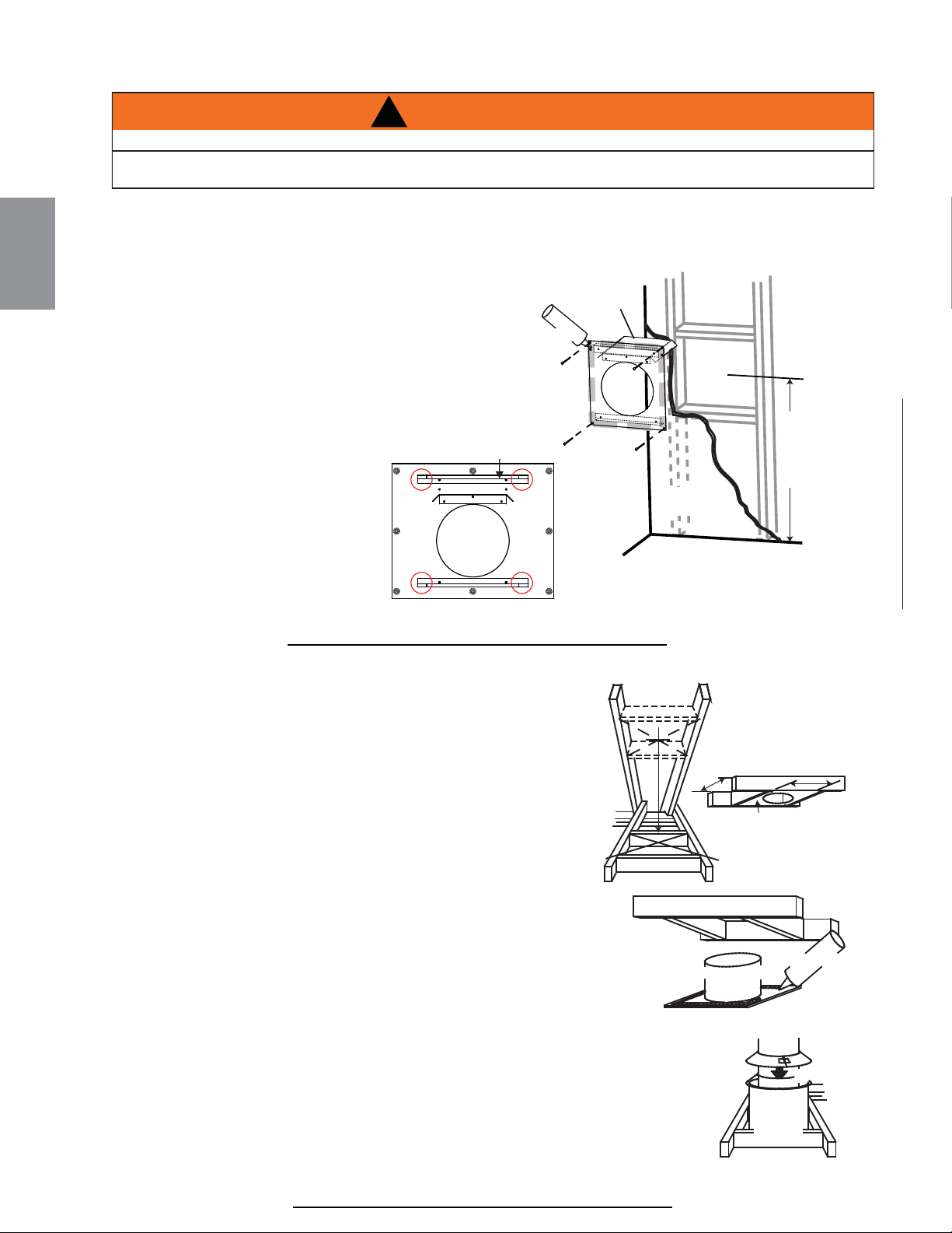
20.7A
!
AVERTISSEMENT
L’ESPACEUR COUPE-FEU DOIT ÊTRE INSTALLÉ AVEC L’ÉCRAN PROTECTEUR ORIENTÉ VERS LE HAUT.
LA TERMINAISON NE DOIT PAS ÊTRE ENCHÂSSÉE DANS LE MUR OU LE REVÊTEMENT EXTÉRIEUR
PLUS QUE L’ÉPAISSEUR DE LA BRIDE DE LA PLAQUE DE MONTAGE.
DÉTERMINEZ
LA BONNE
HAUTEUR
CALFEUTRAGE
ESPACEUR
COUPE-FEU
PROTECTEUR
DE CONDUIT
D’ÉVACUATION
MATÉRIAU
DE FINITION
Cette confi guration s’applique lorsque le conduit
d’évent traverse un mur extérieur. Une fois que vous aurez déterminé la hauteur exacte pour l’emplacement de la
terminaison, découpez et charpentez
une ouverture dans le mur extérieur (comme illustré) pour permettre
l’installation de l’espaceur coupe-feu. Avant de continuer, placez
l’espaceur coupe-feu dans l’ouverture pour vous assurer que les
supports sur la surface arrière soient placés contre la
face intérieure de la pièce de charpente horizontale.
L’écran protecteur doit être installer pour protéger toute la
profondeur de la pénétration de la paroi combustible. La
longueur de l’écran protecteur peut être taillé pour des murs
combustibles qui ont moins de 6 “(152 mm) d’épaisseur.
NOTE: Pliez les onglets pour les dégagements latéraux
réduits ou déplacer le bouclier Meilleurs jeux réduits.
A. Appliquez un joint de calfeutrage
(non fourni) tout autour de la
bordure de la face intérieure de
l’espaceur coupe-feu, installez
l’espaceur coupe-feu contre le
trou et fi xez à l’aide des quatre
vis (fournies dans le sac de
votre manuel).
B. Une fois que le conduit d’évent
est en place, appliquez du scellant à haute température W573-0007 (non fourni) entre le conduit d’évent et
l’espaceur coupe-feu.
Cette confi guration s’applique lorsque l’évacuation se fait à travers un
toit. Des ensembles d’installation pour les différentes pentes de toit sont
disponibles chez votre détaillant autorisé. Voir la section « Accessoires »
pour commander l’ensemble spécifi que dont vous avez besoin.
A. Une fois que vous aurez déterminé l’emplacement de la terminaison,
découpez et charpentez une ouverture dans le plafond et le toit
pour laisser le dégagement minimal de 1” (25,4mm) entre le conduit
d’évent et tout matériau combustible. Essayez de positionner le
conduit d’évent à michemin entre deux solives pour ne pas être
obligé de les couper. Utilisez du fi l à plomb pour aligner le centre des
ouvertures. Un protecteur de conduit d’évacuation empêchera tout
matériau, tel que l’isolant, de remplir l’espace vide de 1” (25,4mm)
autour de l’évent. Fixez des entretoises entre les solives pour
assurer un support additionnel.
B. Appliquez un joint de calfeutrage (non fourni) sur la charpente ou sur
le protecteur de conduit d’évacuation Wolf Steel ou l’équivalent
(dans le cas d’un plafond fi ni) et fi xez le protecteur de conduit
d’évacuation de façon à recouvrir l’ouverture dans le plafond. Un
espaceur coupe-feu doit être fi xé à la base de chaque ouverture
charpentée dans un toit ou un plafond par lequel traverse le système
d’évacuation. Appliquez un joint de calfeutrage tout autour et placez un espaceur coupe-
feu par-dessus le protecteur de conduit d’évacuation pour empêcher l’arrivée d’air froid
dans la pièce ou autour de l’appareil. Assurez-vous que l’espaceur coupe-feu et le
protecteur de conduit d’évacuation conservent le dégagement nécessaire aux matériaux
combustibles. Une fois que le conduit d’évacuation est en place, appliquez un agent
d’étanchéité entre le conduit d’évacuation et l’espaceur coupe-feu.
C. Dans le grenier, faites glisser le collet de conduit d’évacuation vers le bas afi n de
recouvrir l’extrémité ouverte du protecteur de conduit d’évacuation et serrez. Ceci
empêchera tout matériau, tel que l’isolant, de remplir l’espace vide de 1 po (25,4mm) autour de l’évent.
21.1A
CALFEUTRAGE
PROTECTEUR
DU CONDUIT
D’ÉVACUATION
ESPACEUR
COUPE-FEU
FACE INFÉRIEURE
DES SOLIVES
COLLET DE
CONDUIT
D’ÉVACUATION
PROTECTEUR
DU CONDUIT
D’ÉVACUATION
106
W415-1401 / C / 03.19.15
FR
4.1.1 INSTALLATION HORIZONTALE
4.1.2 INSTALLATION VERTICALE
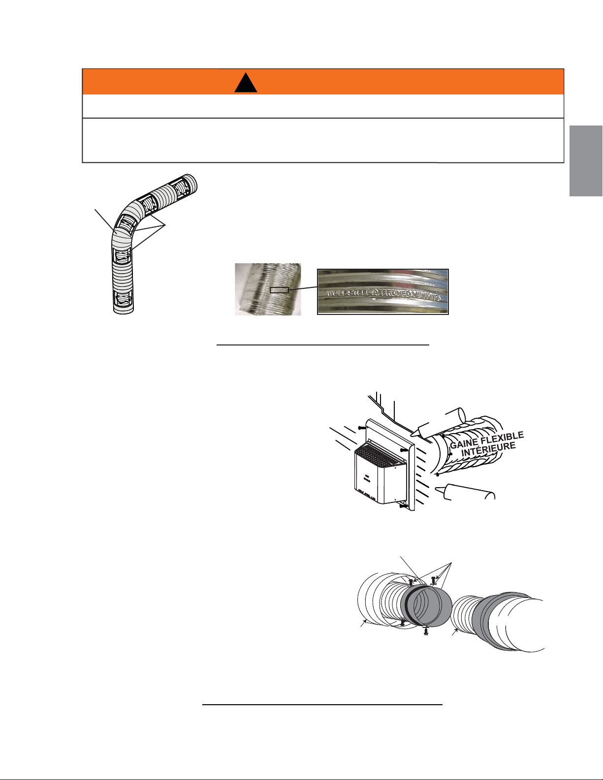
Afi n d’assurer une opération sécuritaire et adéquate de l’appareil, vous devez
observer les instructions d’évacuation à la lettre.
Tous les joints des conduits fl exibles intérieurs et extérieurs peuvent être
scellés avec le scellant à haute température W573-0002 (non fourni) ou du
scellant à haute température Mill Pac W573-0007 (non fourni). Cependant,
le raccordement du conduit fl exible intérieur à la buse de l’appareil doit être
scellé avec le scellant Mill Pac W573-0007 (non fourni).
N’utilisez que les ensembles certifi és de gaines fl exibles portant
l’inscription :
22.1
COUDE
ESPACEURS
NE LAISSEZ PAS LA GAINE FLEXIBLE SE TASSER CONTRE LES COURSES HORIZONTALES OU VERTICALES
ET LES COUDES. GARDEZ-LA TENDUE.
DES ESPACEURS SONT FIXÉS À LA GAINE FLEXIBLE À INTERVALLES PRÉDÉTERMINÉS AFIN DE GARDER
UN ESPACE VIDE AVEC LE CONDUIT EXTÉRIEUR. POUR QUE LE FONCTIONNEMENT SOIT SÉCURITAIRE, UN
ESPACE VIDE EST REQUIS. UN ESPACEUR EST REQUIS AU DÉBUT, AU MILIEU ET À LA FIN DE CHAQUE
COUDE AFIN DE MAINTENIR CET ESPACE VIDE. N'ENLEVEZ PAS CES ESPACEURS.
!
AVERTISSEMENT
« Wolf Steel Approved Venting » comme
identifi é par la gaine fl exible extérieure.
23.1B
VIS
#10x2"
CHEVAUCHEMENT
DE 2” (50.8mm)
SCELLANT À HAUTE
TEMPÉRATURE
SCELLANT À
HAUTE
TEMPÉRATURE
VIS AUTOPERCEUSES
#8 X 1/2" & RONDELLES
BAGUES D'ACCOUP.
INTERNE ET EXTERNE
GAINE
FLEXIBLE
EXTÉRIEURE
GAINE
FLEXIBLE
INTÉRIEURE
GAINE FLEXIBLE
EXTÉRIEURE
CALFEUTRAGE
7" (177.8mm)
GAINE FLEXIBLE
4” (101.6mm) GAINE FLEXIBLE
A. Étirez la gaine fl exible intérieure à la longueur
requise en tenant compte de la longueur
additionnelle nécessaire pour la surface du mur fi ni.
Appliquez un généreux joint de scellant à haute
température W573-0007 Mill Pac (non fourni).
Glissez la gaine fl exible sur le manchon intérieur de
la terminaison en assurant un chevauchement minimal
de 2” (50.8mm) et fi xez à l’aide de trois vis #8.
B. Installez la gaine fl exible extérieure en la glissant
sur le manchon extérieur de la terminaison et fi xez à
l’aide de trois vis #8. Scellez avec du scellant à haute
température W573-0002 (non fourni).
C. Insérez les gaines dans le coupe-feu tout en
conservant le dégagement nécessaire aux matériaux
combustibles. En soutenant la terminaison (les
inscriptions étant à l’endroit et lisibles), fi xez la
terminaison au mur extérieur et rendez-la étanche
en la scellant avec du calfeutrage (non fourni).
D. Si plus de sections de gaine doivent être utilisées
pour atteindre l’appareil, raccordez-les ensemble
tel qu’illustré. Le système d’évacuation doit
être soutenu à environ tous les 3 pieds (0.9m)
pour les courses verticales et horizontales.
Utilisez des supports incombustibles afi n de
maintenir le dégagement minimal aux matériaux
combustibles.
Les terminaisons ne doivent pas être enchâssées dans un mur ou un revêtement extérieur plus que
l’épaisseur de la bride de la plaque de montage.
SCELLANT À HAUTE
TEMPÉRATURE
GAINE FLEXIBLE
EXTÉRIEURE
CALFEUTRAGE
VIS
#10x2"
CHEVAUCHEMENT DE
2” (50.8mm)
107
W415-1401 / C / 03.19.15
FR
4.2 UTILISATION DE COMPOSANTS FLEXIBLES D’ÉVACUATION
4.2.1 INSTALLATION DE LA TERMINAISON HORIZONTALE
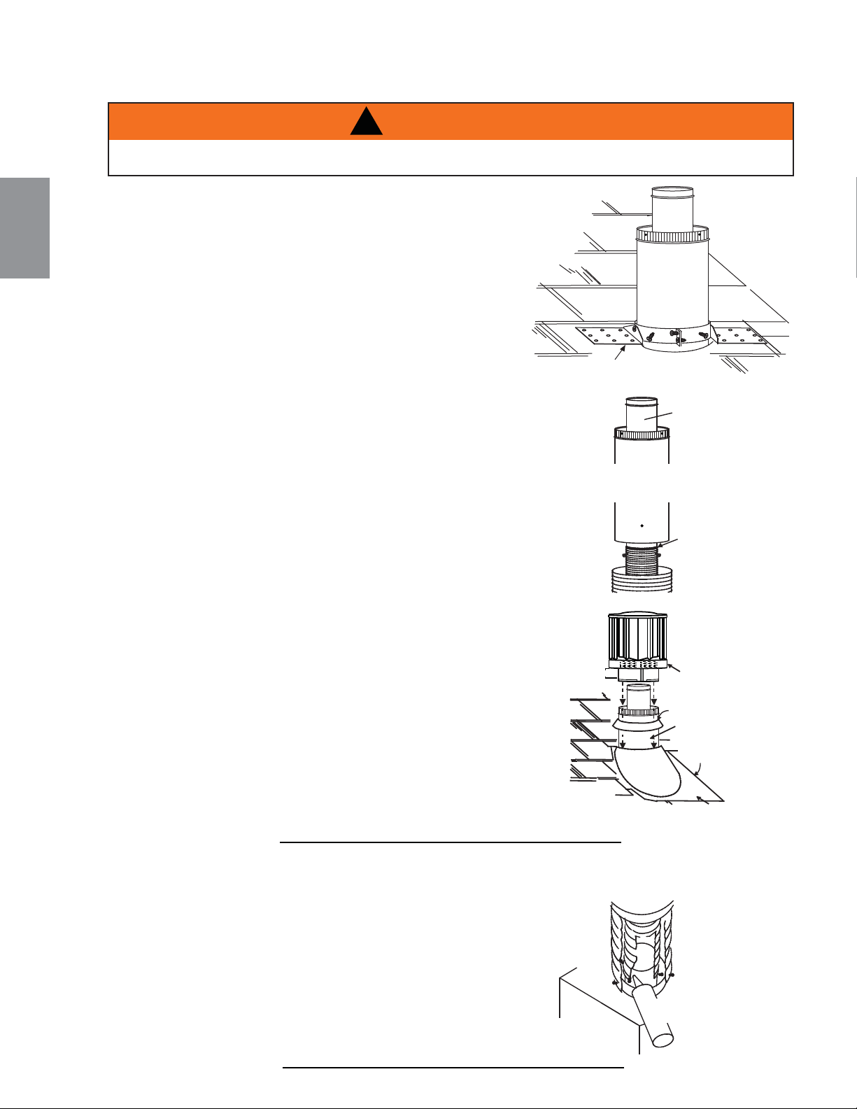
A. Fixez le support de toit au toit à l’aide des vis fournies. Le support
de toit est optionnel. Dans ce cas, l’évent doit être supporté
adéquatement soit en utilisant une méthode alternative se
conformant aux normes des autorités compétentes, soit en utilisant
le support de toit optionnel.
B. Étirez la gaine fl exible intérieure à la longueur requise.
Glissez la gaine fl exible intérieure sur le manchon
intérieur du connecteur de terminaison en assurant un
chevauchement minimal de 2” (50,8mm) et fi xez à l’aide
de trois vis #8. Scellez en appliquant un généreux joint de
scellant à haute température W573-0007 (non fourni).
C. Installez la gaine fl exible extérieure de la même façon et
scellez en appliquant un généreux joint de scellant à haute
température W573-0002 (non fourni).
D. Faites passer le montage du connecteur de terminaison/gaines fl exibles
à travers le toit. La terminaison doit être verticale et d’aplomb. Fixez
le connecteur de terminaison au support de toit en vous assurant que
le dessus de la terminaison excède le côté le plus élevé du toit d’au
moins 16” (406,4mm) une fois fi xée.
E. Enlevez les clous des bardeaux sur le dessus et les côtés du
connecteur de terminaison. Placez le solin par-dessus le connecteur de
terminaison en laissant un minimum de 3/4” (19,1mm) de connecteur
de terminaison visible au-dessus du haut du solin. Glissez le solin
sous les côtés et le bord supérieur des bardeaux. Assurez-vous que
le connecteur de terminaison est bien centré dans le solin, en laissant
une marge de 3/4” (19,1mm) tout autour. Fixez-le au toit. Ne clouez
pas à travers la partie inférieure du solin. Imperméabilisez-le en le
scellant avec du calfeutrage. Si possible, recouvrez les côtés et le
bord supérieur du solin avec des matériaux de couverture.
F. Alignez les joints de la terminaison et du connecteur de
terminaison et placez la terminaison par-dessus le connecteur
de terminaison en vous assurant que le manchon pénètre dans
le trou de la terminaison. Fixez à l’aide des trois vis fournies.
G. Appliquez un généreux joint de calfeutrage à l’épreuve de l’eau à
2” (50,8mm) au-dessus du solin. Installez le collet de solin autour
de la terminaison et glissez-le jusqu’à la ligne de calfeutrage.
Serrez afi n d’assurer l’étanchéité entre la terminaison et le collet.
H. Si plus de sections de gaine doivent être utilisées pour atteindre
l’appareil, voir la section « INSTALLATION DE LA TERMINAISON
HORIZONTALE ».
2”
(50,8mm)
COLLET DE SOLIN
SOLIN
CALFEUTRAGE
SCELLANT
BASE DE
PRISE D’AIR
GAINE FLEXIBLE
GAINE FLEXIBLE
GAINE
INTÉRIEURE
SCELLANT À
HAUTE
TEMPÉRATURE
CONNECTEUR DE
TERMINAISON
SUPPORT DE TOIT
24.1A
CONSERVEZ UN ESPACE MINIMAL DE 2" (50,8mm) ENTRE LA BASE DE LA PRISE D’AIR ET LE
COLLET DE SOLIN.
!
AVERTISSEMENT
A. Raccordez la collet d’évacuation à l’appareil. Fixez-la à
l’aide de trois vis. Scellez le joint et les têtes de vis avec
le scellant à haute température Mill-Pac W573-0007 (non
fourni).
B. Raccordez la gaine fl exible à l’appareil. Fixez et scellez les
joints avec le scellant à haute température.
28.1C
CHEVAUCHEMENT
DE 2” (50,8mm)
SCELLANT À HAUTE
TEMPÉRATURE
VIS
AUTOPER-
CEUSES
#8 X 1/2”
108
W415-1401 / C / 03.19.15
FR
4.2.2 INSTALLATION DE LA TERMINAISON VERTICALE
4.2.3 RACCORDEMENT DES ÉVENTS À L'APPAREIL
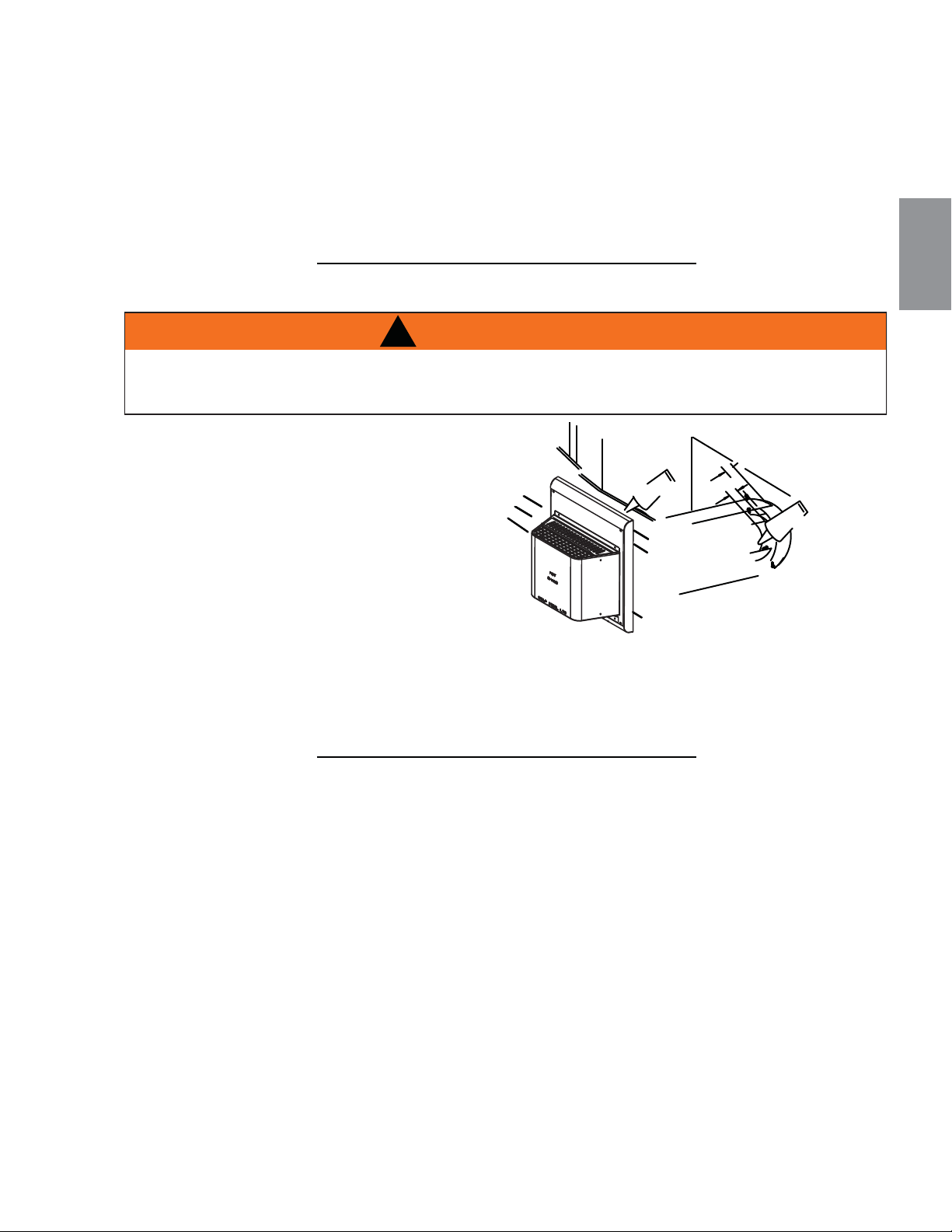
Le système d’évacuation doit être soutenu à peu près tous les 3 pieds (0.9m) de courses verticales et horizontales.
Utilisez l’ensemble de support mural Wolf Steel ou des supports incombustibles équivalents afi n de conserver le
dégagement minimal aux matériaux combustibles pour les courses verticales et horizontales.
Tous les joints des conduits intérieurs et extérieurs peuvent être scellés avec du scellant de silicone rouge à haute
température W573-0002 (non fourni) ou du scellant noir à haute température Mill Pac W573-0007 (non fourni) à
l’exception du raccordement du conduit d’évacuation à la buse de l’appareil qui doit être scellé avec le scellant
Mill Pac.
25.1A
A. Mettez l’appareil en place. Mesurez la longueur
d’évent requise entre la terminaison et l’appareil
en tenant compte de la longueur additionnelle
nécessaire pour la surface du mur fi ni et tout
chevauchement de 1 ¼” (31.8mm) entre les
composants d’évacuation.
B. Appliquez du scellant à haute température
W573-0007 (non fourni) sur le rebord extérieur
du collet intérieur de l’appareil. Installez le premier
évent et fi xez-le en utilisant 3 vis autoperceuses.
Procédez de la même façon avec l’évent rigide
extérieur.
C. Insérez les deux évents dans l’espaceur coupe-feu, en respectant les dégagements aux combustibles
requis. En soutenant la terminaison (les inscriptions étant à l’endroit et lisibles), fi xez-la au mur extérieur et
rendez-la étanche en la scellant avec du calfeutrage (non fourni).
La plaque de montage de la terminaison peut être enchâssée dans le mur ou le revêtement extérieur, sans
excéder l’épaisseur de la bride.
26.1A
#10x2"
VIS
CALFEUTRAGE
INTÉRIEUR
AUTOPERCEUSES
VIS
#8x1/2"
CHEVAUCHEMENT DE
1” (25mm)
HAUTE TEMP.
SCELLANT
RIGIDE
ÉVENT
EXTÉRIEUR
ÉVENT
RIGIDE
109
W415-1401 / C / 03.19.15
FR
4.3 UTILISATION DE COMPOSANTS RIGIDES D’ÉVACUATION
4.3.1 INSTALLATION DE LA TERMINAISON HORIZONTALE
!
AVERTISSEMENT
RISQUE D'INCENDIE. ÉVITEZ QUE L'ISOLANT TOUCHE AU CONDUIT D'ÉVACUATION. RETIREZ
L'ISOLANT POUR PERMETTRE L'INSTALLATION DE L'ÉCRAN PROTECTEUR DU GRENIER ET POUR
MAINTENIR LES DÉGAGEMENTS AUX MATÉRIAUX COMBUSTIBLES.
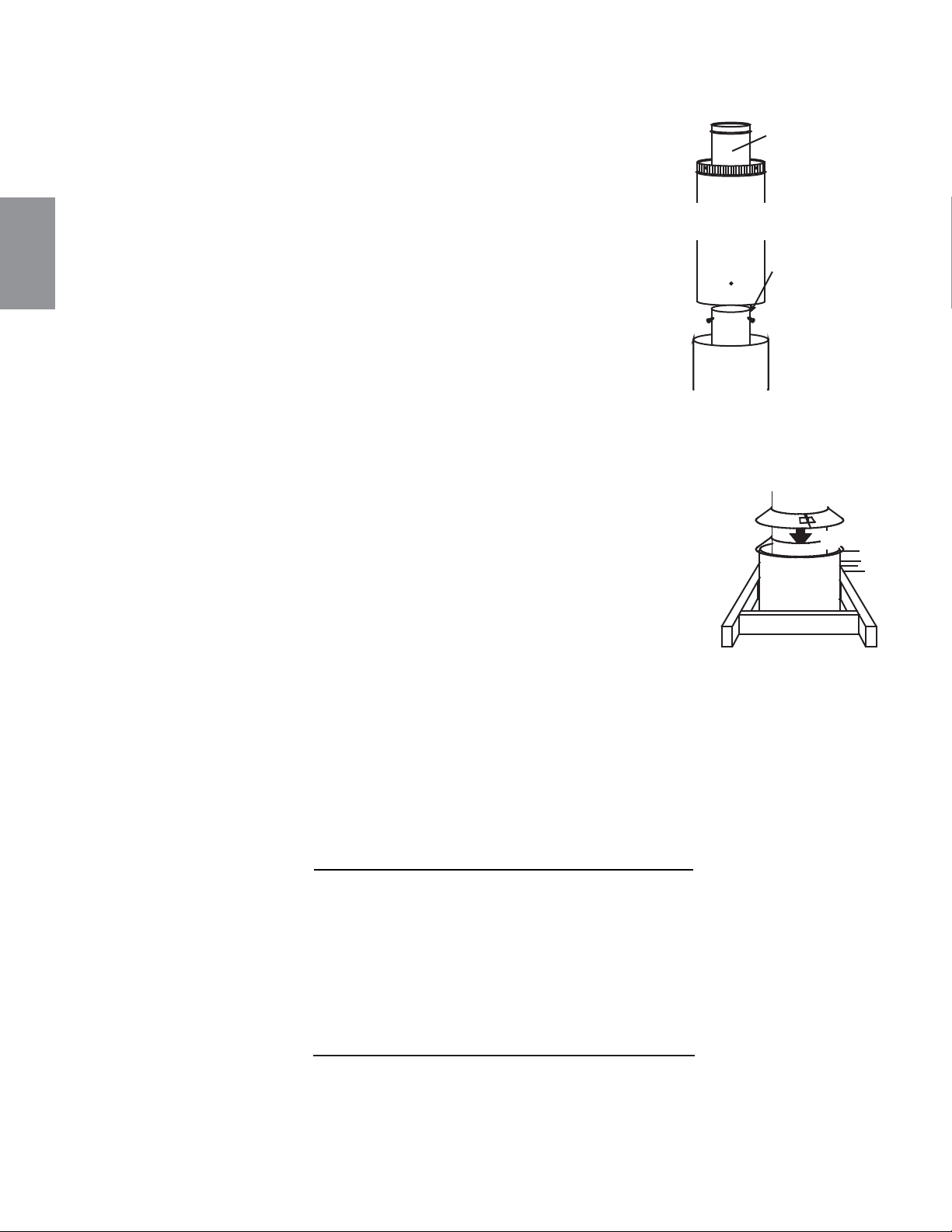
A. Mettez l’appareil en place.
B. Fixez le support de toit au toit à l’aide des vis fournies. Le support de toit
est optionnel. Dans ce cas, l’évent doit être supporté adéquatement, soit en
utilisant une méthode alternative se conformant aux normes des autorités
compétentes, soit en utilisant le support de toit optionnel.
C. Appliquez du scellant à haute température (non fourni) sur le rebord extérieur
du manchon intérieur de la terminaison. Glissez une bague d’accouplement
sur au moins 2" (51mm) du manchon et fi xez-la à l’aide de 3 vis.
D. Appliquez du scellant à haute température (non fourni) sur le rebord
extérieur du manchon extérieur de la terminaison. Glissez une bague
d’accouplement sur le manchon et fi xez comme auparavant. Taillez la
bague d’accouplement extérieure à la même longueur que la bague
d’accouplement intérieure.
E. Faites passer l’ensemble de terminaison à travers le support de toit. Fixez
l’ensemble de terminaison au support de toit en vous assurant que la
section de terminaison excède le toit d’au moins 16" (406mm) une fois
fi xée. Si l’espace du grenier est restreint, nous recommandons de visser
le collet de conduit d’évacuation Wolf Steel ou l’équivalent sans serrer dans l’ensemble de la terminaison
lorsqu’il est passé à travers le grenier. La terminaison doit être verticale et d’aplomb.
F. Enlevez les clous des bardeaux sur le dessus et les côtés de la cheminée. Placez le
solin par-dessus la terminaison et glissez-le sous les côtés et le bord supérieur des
bardeaux. Assurez-vous que la terminaison est bien centrée dans le solin, en laissant
une marge de 3/4" (19mm) tout autour. Fixez-le au toit. NE clouez PAS à travers la
partie inférieure du solin. Imperméabilisez-le en le scellant avec du calfeutrage. Si
possible, recouvrez les côtés et le bord supérieur du solin avec des matériaux de
couvertures.
G. Appliquez un généreux joint de calfeutrage à l’épreuve de l’eau à 2" (51mm) au-
dessus du solin. Installez le collet de solin autour du connecteur de terminaison et
glissez-le jusqu’à la ligne de calfeutrage. Serrez afi n d’assurer l’étanchéité entre le
connecteur de terminaison et le collet.
H. Continuez d’ajouter des sections rigides d’évacuation, fi xez et scellez comme ci-dessus. Installez le manchon
télescopique intérieur en position fermé à la dernière section de conduit rigide. Fixez-le avec des vis et
scellez. Procédez de la même façon avec le manchon télescopique extérieur.
I. Appliquez un joint de scellant à haute température (non fourni) sur le côté extérieur du collet de conduit
d’évacuation intérieur sur l’appareil. Glissez le manchon télescopique sur une longueur d’au moins 2" (51mm)
par-dessus le collet de conduit d’évacuation. Fixez avec trois vis. Procédez de la même façon avec le
manchon télescopique extérieur.
J. Dans le grenier, faites glisser le collet de conduit d’évacuation vers le bas afi n de recouvrir l’extrémité ouverte
du protecteur de conduit d’évacuation et serrez. Ceci empêchera tout matériau, tel que l’isolant, de remplir
l’espace vide de 1" (25mm) autour de l’évent.
27.2A
CONDUIT
RIGIDE
INTÉRIEUR
CONDUIT
RIGIDE
EXTÉRIEUR
CONDUIT
SCELLANT À
HAUTE
TEMPÉRATURE
CONNECTEUR
DE
TERMINAISON
INTÉRIEUR
PROTECTEUR
DE CONDUIT
D’ÉVACUATION
COLLET
DE CONDUIT
D’ÉVACUATION
110
W415-1401 / C / 03.19.15
FR
77.3
C
ertaines con
fi
gurations d’évacuation verticales peuvent avoir une
fl
amme très active.
S
i cette apparence
n’est pas désirée, la sortie du conduit d’évacuation doit être réduite en utilisant une plaque de restriction. Pour
obtenir l’ensemble approprié, voir les « ACCESSOIRES » à la section « RECHANGES ». Ceci diminuera la
vélocité des gaz de combustion, ralentissant ainsi le mouvement de la fl amme et créant une apparence plus
traditionnelle. Les instructions sont incluses avec l’ensemble.
4.3.2 INSTALLATION DE LA TERMINAISON VERTICALE
4.4 RESTREIGNANT DES ÉVENTS VERTICAUX
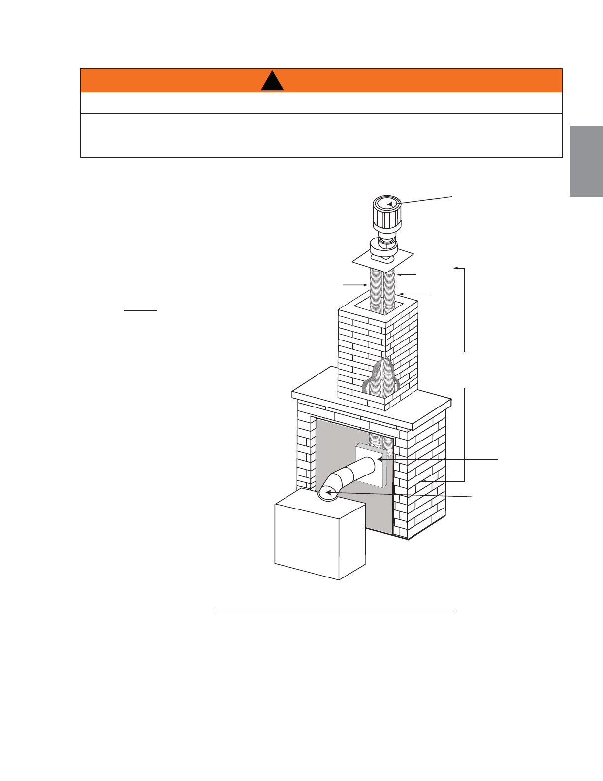
111
W415-1401 / C / 03.19.15
FR
7.6A
Cet appareil est conçu pour être raccordé à un système d’évent fl exible colinéaire de 3” (76,2mm) en
aluminium se prolongeant sur toute la longueur de la cheminée de maçonnerie.
Les conduits fl exibles s’adaptent à tous les contours d’une
cheminée de maçonnerie. Néanmoins, vous devez garder
les conduits fl exibles aussi droit que possible. Le collet
de prise d’air de la terminaison doit être raccordé au
conduit fl exible de prise d’air et le collet d’évacuation
de la terminaison au conduit fl exible d’évacuation.
Les adaptateurs colinéaire à coaxial Simpson
Duravent et Selkirk sont approuvés pour cet
appareil (NOTE : Un adaptateur d’évent sera
nécessaire directement à partir de l’appareil).
Suivez les instructions d’installation du fabricant
du système d’évacuation.
Des composants d’évacuation de différents
fabricants ne doivent pas être combinés. Une
fois que l’adaptateur de votre choix est installé,
le reste du système d’évacuation doit provenir
du même fabricant.
La seule exception à cette règle est l’usage du
système de conduit fl exible de 3” (76,2mm) et
de terminaison colinéaire Wolf Steel.
RISQUE D'INCENDIE!
LES CONFIGURATIONS D'ÉVACUATION COAXIALES À COLINÉAIRES NE DOIVENT ÊTRE UTILISÉES
QUE DANS UNE CHEMINÉE OU UNE ENCEINTE DE NATURE INCOMBUSTIBLE. UNE INSTALLATION
DANS UNE ENCEINTE COMBUSTIBLE PEUT CAUSER UN INCENDIE.
!
AVERTISSEMENT
PRISE
D’AIR
ÉVACUATION
CONDUIT
FLEXIBLE
* 40 PIEDS
(12,2m) MAX.
10 (3,1m)PIEDS
MIN.
ADAPTATEUR
COAXIAL À
COLINÉAIRE
ADAPTATEUR
D'ÉVENT DE
L'APPAREIL
TERMINATION
* Mesurée à partir de la buse de l’appareil
jusqu’au collet de la terminaison.
4.5 TERMINAISON VERTICALE À TRAVERS UNE CHEMINÉE EXISTANTE

Cet appareil est certifi é pour être installé comme équipement d’origine (OEM) dans une maison préfabriquée ou
une maison mobile. Son installation doit être effectuée en respectant les directives du fabricant et le Manufactured
Home Construction and Safety Standard, Title 24 CFR, Part 3280, aux États-Unis, ou les normes actuelles pour les
maisons mobiles, CAN/CSA Z240 SÉRIE MH, au Canada. Cet appareil ne doit être utilisé qu’avec le type de gaz
indiqué sur la plaque d’homologation. Un ensemble de conversion est fourni avec l’appareil pour maison mobile.
29.1A
Cet appareil homologué pour les maisons mobiles et préfabriquées possède des éléments de fi xation. L’appareil est
muni de deux trous de ¼” (6,4mm)de diamètre, situés aux coins avant, gauche et droit de la base. Lors d’une installation
dans une maison mobile, l’appareil doit être fi xé au plancher. Fixez à l’aide de vis #10 à tête hexagonale insérées dans
les trous de la base. Éteignez toujours la veilleuse et l’alimentation en gaz à la source avant de déplacer la maison
mobile. Après avoir déplacé la maison mobile et avant d’allumer l’appareil, assurez-vous que les bûches sont placées
correctement.
Cet appareil est certifi é pour être installé dans une maison mobile installée de façon permanente, sauf si les codes
locaux l’interdisent. Cet appareil ne doit être utilisé qu’avec le type de gaz indiqué sur la plaque d’homologation. On
ne peut utiliser cet appareil avec d’autres types de gaz, sauf si un ensemble de conversion certifi é est utilisé.
Ensembles de conversion
L’appareil pour maison mobile peut être converti au gaz naturel (GN) ou au propane (PL). Pour effectuer une
conversion, veuillez consulter votre détaillant autorisé.
112
W415-1401 / C / 03.19.15
FR
4.6 INSTALLATION DANS UNE MAISON MOBILE
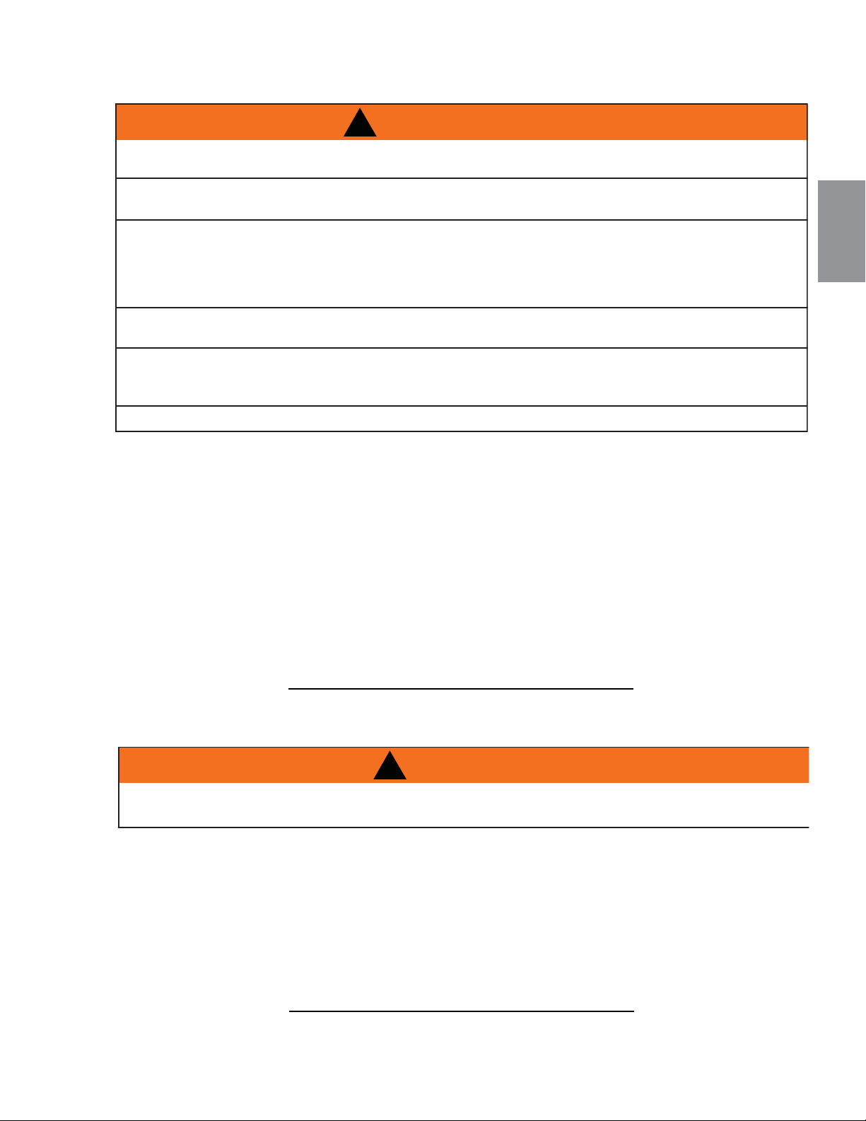
Pour faciliter l’accès, un interrupteur mural ou un thermostat millivolt optionnel peut être installé à un endroit
pratique. Passez un fi l millivolt à deux brins (noyau solide) de la soupape à l’interrupteur mural ou au thermo-
stat millivolt. La longueur maximale dépend du calibre du fi l :
DIAMÈTRE DU FIL LONGUEUR MAX.
Calibre 14 (1,8mm) 100 pieds (30,5m)
Calibre 16 (1,5mm) 60 pieds (18,3m)
Calibre 18 (1,2mm) 40 pieds (12,2m)
* Voir la section ”SCHÉMA DE CÂBLAGE”
50.6
!
AVERTISSEMENT
NE RACCORDEZ PAS L’INTERRUPTEUR MURAL, LE THERMOSTAT OU LA SOUPAPE DE GAZ À
L’ALIMENTATION ÉLECTRIQUE DE 110 VOLTS.
113
W415-1401 / C / 03.19.15
FR
4.7 BRANCHEMENT DU GAZ
30.1A
L’installation et l’entretien doivent être effectués par un installateur qualifi é.
A. Mettez l’appareil en place et fi xez-le.
B. Si l’appareil est muni d’un raccord fl exible, celui-ci est conçu pour recevoir une conduite de gaz de
1/2”. Sans raccord fl exible, l’appareil est conçu pour recevoir une conduite de gaz de 3/8”. L’appareil
est muni d’une soupape d’arrêt manuelle pour fermer l’alimentation en gaz.
C. Branchez le gaz en conformité avec les codes locaux. En l’absence de codes locaux, l’installation doit
être conforme au Code d’installation du gaz CAN/CSA-B149.1 dans sa version pour le Canada ou le
National Fuel Gas Code, ANSI Z223.1 / NFPA 54 pour les États-Unis.
D. Lorsque vous manipulez des conduites de gaz, soutenez la soupape de gaz pour éviter que les con-
duites ne se plient.
E. Le raccord fl exible de l’alimentation en gaz devrait être suffi samment mobile pour permettre de placer
l’assemblage du brûleur sur le côté.
F. Vérifi ez pour des fuites de gaz en appliquant une solution d’eau savonneuse. N’utilisez pas une
fl amme nue.
!
AVERTISSEMENT
RISQUE D'INCENDIE, D'EXPLOSION OU D'ASPHYXIE. ASSUREZ-VOUS QU'IL N'Y AIT AUCUNE SOURCE
D'ALLUMAGE COMME DES ÉTINCELLES OU UNE FLAMME NUE.
SOUTENEZ LE CONTRÔLE DU GAZ LORSQUE VOUS ATTACHEZ LE TUYAU POUR ÉVITER DE PLIER LA CON-
DUITE DE GAZ.
ALLUMEZ TOUJOURS LA VEILLEUSE, QUE CE SOIT POUR LA PREMIÈRE FOIS OU LORSQUE
L’APPROVISIONNEMENT EN GAZ EST ÉPUISÉ, AVEC LA PORTE VITRÉE OUVERTE OU RETIRÉE. LA PURGE
DOIT ÊTRE EFFECTUÉE PAR UN TECHNICIEN QUALIFIÉ. ASSUREZ-VOUS QUE L’ARRIVÉE DE GAZ AU BRÛLEUR
EST CONTINUE AVANT DE FERMER LA PORTE. ASSUREZ-VOUS D’UNE VENTILATION ADÉQUATE. POUR LES
EMPLACEMENTS DE L’ENTRÉE DU GAZ ET DE L’ENTRÉE ÉLECTRIQUE, VOIR LA SECTION « DIMENSIONS ».
LORSQUE LE BRANCHEMENT EST TERMINÉ, TOUS LES RACCORDS DE GAZ DOIVENT SE TROUVER À
L’INTÉRIEUR DU FOYER.
LES PRESSIONS ÉLEVÉES ENDOMMAGERONT LA SOUPAPE. L’ALIMENTATION EN GAZ DOIT ÊTRE
DÉBRANCHÉE PENDANT LES ESSAIS DE PRESSION DE CE SYSTÈME LORSQUE LES PRESSIONS D’ESSAI
EXCÈDENT ½ LB/PO² (3,5 KPA).
LES RÉGLAGES DE LA SOUPAPE ONT ÉTÉ FAITS EN USINE; NE LES MODIFIEZ PAS.
4.8 INTERRUPTEUR MURAL OPTIONNEL
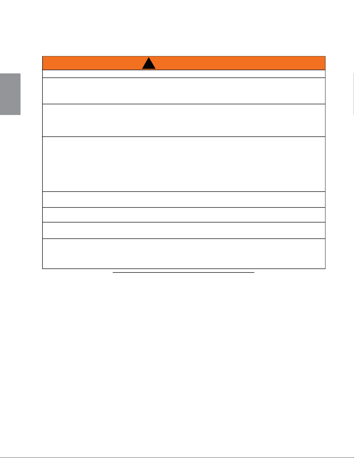
!
AVERTISSEMENT
RISQUE D’INCENDIE!
AFIN D’ÉVITER LA POSSIBILITÉ QUE DE L’ISOLATION OU UN COUPE-VAPEUR ENTRENT EN CON-
TACT AVEC L’EXTÉRIEUR DU CAISSON, IL EST CONSEILLÉ D’INSTALLER L’APPAREIL CONTRE DES
MURS FINIS (C.-À-D. PANNEAU DE GYPSE) COMME TOUT AUTRE MUR DE LA MAISON. CECI
ASSURERA QUE LE DÉGAGEMENT AUX MATÉRIAUX COMBUSTIBLES EST MAINTENU.
NE FAITES PAS D’ENTAILLES À L’OSSATURE AUTOUR DES ESPACEURS. NE PAS MAINTENIR LES
DÉGAGEMENTS PEUT CAUSER UNE SURCHAUFFE ET UN INCENDIE. EMPÊCHEZ TOUT CONTACT
AVEC DE L'ISOLANT QUI S'AFFAISSE, AVEC L’OSSATURE OU AVEC TOUT AUTRE MATÉRIAU COM-
BUSTIBLE. BLOQUEZ L’ENTRÉE DE L’ENCEINTE POUR EMPÊCHER L'INFILTRATION D'ISOLANT
SOUFFLÉ. ASSUREZ-VOUS QUE L’ISOLATION ET LES AUTRES MATÉRIAUX SONT BIEN FIXÉS.
LORSQUE VOUS CONSTRUISEZ L’ENCEINTE, PRÉVOYEZ L’ÉPAISSEUR DES MATÉRIAUX DE
FINITION POUR MAINTENIR LES DÉGAGEMENTS. SI L’OSSATURE OU LES MATÉRIAUX DE FINITION
SE TROUVENT À UNE DISTANCE INFÉRIEURE À CELLE INDIQUÉE, ILS DOIVENT ÊTRE FAITS
ENTIÈREMENT DE MATÉRIAUX NON COMBUSTIBLES. LES MATÉRIAUX FAITS ENTIÈREMENT
D’ACIER, DE FER, DE BRIQUE, DE TUILE, DE BÉTON, D’ARDOISE, DE VERRE OU DE PLÂTRE, OU
D’UNE COMBINAISON DE CES MATÉRIAUX, SONT APPROPRIÉS. LES MATÉRIAUX RÉPONDANT À LA
NORME ASTM E 136, MÉTHODE DE TEST STANDARD DU COMPORTEMENT DES MATÉRIAUX DANS
UNE FOURNAISE AVEC TUBE VERTICAL À 1382° F (750°C), ET À LA NORME UL763 SONT
CONSIDÉRÉS COMME ÉTANT DES MATÉRIAUX NON COMBUSTIBLES.
AFIN D'ÉVITER UN RISQUE D'INCENDIE, LES DÉGAGEMENTS MINIMAUX AUX MATÉRIAUX
COMBUSTIBLES DOIVENT ÊTRE MAINTENUS.
L’ENCEINTE DE L’APPAREIL DOIT RESPECTER LA HAUTEUR MINIMALE REQUISE. MESUREZ À
PARTIR DE LA BASE DE L’APPAREIL.
SI DES ENSEMBLES DE MONTANTS EN ACIER AVEC PANNEAU DE CIMENT SONT FOURNIS, OU
SPÉCIFIÉ DANS LES INSTRUCTIONS D’INSTALLATION, ILS DOIVENT ÊTRE INSTALLÉS.
LES MATÉRIAUX DE FINITION DOIVENT ÊTRE NON COMBUSTIBLES PLACER ÉCLAT AVEC LA FACE
DE L’APPAREIL ÉTENDUE DU SOMMET DE L’APPAREIL COMME LE CONSEIL DE CIMENT, LE CAR-
REAU EN CERAMIQUE, LE MARBRE, ETC. NE PAS UTILISÉ DES BÛCHES OU LE CLOISON SECHE.
N'IMPORTE QUEL FEU A ÉVALUÉ DU CLOISON SÈCHE N'EST PAS ACCEPTABLE.
71.1B
114
W415-1401 / C / 03.19.15
FR
5.0 OSSATURE
5.1 L'OSSATURE B36
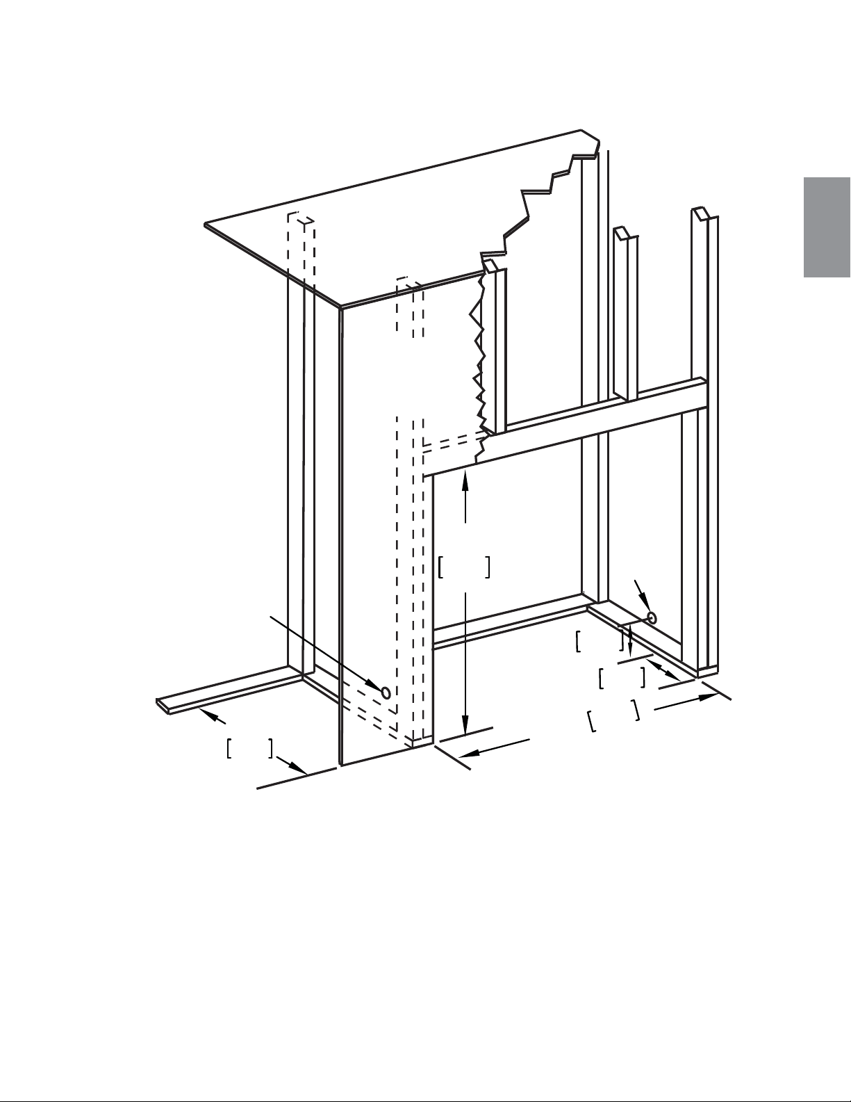
115
W415-1401 / C / 03.19.15
FR
5.1.1 DIMENSIONS MINIMALES DE L’OSSATURE B36
35 1/2"
902mm
35"
889mm
1 7/8"
47mm
8"
203mm
16"
406mm
DESSUS
DE L’ENCEINTE
MATÉRIAU
DE FINITION
RACCORDEMENT
ÉLECTRIQUE
EMPLACEMENT
DE L’ENTRÉE
DU GAZ
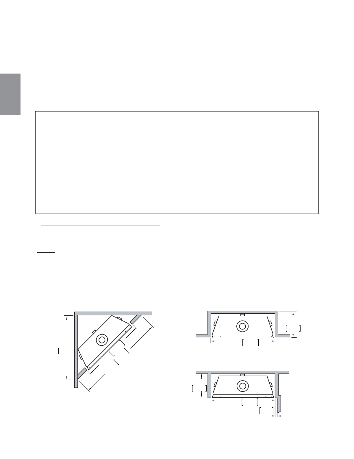
116
W415-1401 / C / 03.19.15
FR
Il est préférable de construire l'ossature après que l'appareil est en place et que le système d'évacuation est
installé. Construisez conformément aux exigences des codes du bâtiment locaux.
Il n'est pas nécessaire d'installer une base de protection avec ce type d'appareil.
Lorsque vous mettez l'appareil en place, surélevez-le de façon à prévoir l'épaisseur du plancher fi ni, c.-à-d.
tuiles, tapis ou bois franc, car s'ils n'ont pas été prévus, ils nuiront à l'ouverture de la porte d'accès inférieure et
à l'installation de plusieurs ensembles de contours.
Les matériaux combustibles peuvent être installés à égalité avec le devant de l'appareil, mais ils ne doivent
recouvrir aucune surface peinte en noir du devant de l'appareil. Les matériaux incombustibles (briques,
pierres, carreaux de céramique) peuvent empiéter sur la partie noire.
* SECTIONS D’ÉVENTS HORIZONTALES B36: Un dégagement minimal aux matériaux combustibles de 1"
(25mm) au-dessous et sur les côtés de l’évent et de 3" (76mm) au-dessus doit être maintenu sur toutes les
courses horizontales. Utilisez l’espaceur coupe-feu W010-3440 (fourni).
NOTE: Les dégagements minimaux entre le haut de l’évent et les matériaux combustibles peut être
réduite de 3" (76mm) à 1" (25mm) dans ces installations avec une event verticale de minimum 38"
(965mm) faite immédiatement au colet due l'appareil.
* SECTIONS D’ÉVENTS VERTICALES B36: Un dégagement minimal aux matériaux combustibles de 1"
(25mm) est requis sur toutes les courses verticales à l’exception des dégagements à l’intérieur de l’enceinte
de l'appareil. Voir la section « DÉGAGEMENTS MINIMAUX DE L’ENCEINTE ». Utilisez l’espaceur coupe-feu
W500-0096 (non fourni).
Dégagements minimaux de l'appareil aux matériaux combustibles :
Ossature combustible :
- 0" aux espaceurs
- 1" (25mm) en dessous et sur les côtés du conduit d’évent*
- 3" (76mm) au-dessus du conduit d’évent*
Finition combustible :
- 0" à l’arrière
- 0" des côtés et du dessus en façade
Évacuation sur le dessus
- 50 1/2" (1283mm) du haut de l’enceinte jusqu’à la base de l’appareil
- 54" (1372mm) du plafond jusqu’à la base de l’appareil
Évacuatn sur l'arrière
- 39" (991mm) du haut de l'enceinte jusqu' à la base de l'appareil
- 54" (1372mm) du plafond jusqu' à la base de l'appareil
-
35 1/2"
902mm
49 1/8"
1248mm
31 7/8"
810mm
ENCEINTE
INTÉRIEURE
ENCEINTE
EXTÉRIEURE
MURALE
CÔTÉ
16”
406mm
16"
406mm
2"
51mm
35 1/2"
902mm
35 1/2"
902mm
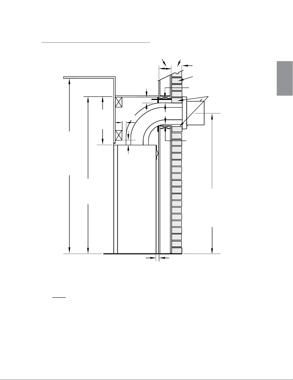
117
W415-1401 / C / 03.19.15
FR
5.2 DÉGAGEMENTS MINIMAUX DE L'ENCEINTE B36
3" [76mm]
COMBUSTIBLE
3" [76mm]
MINIMUM
3" [76mm]
2"
[51mm]
1"
[25mm]
50 1/2"
[1283mm]
16 1/4"
[412mm]
1"
[25mm]
INCOMBUSTIBLE
BRIQUE
0” (0MM) SI LES MATÉRIAUX
SONT INCOMBUSTIBLES,
COMME DE LA BRIQUE
ET DE LA PIERRE.
54"
[1372mm]
PLAFOND
(MIN)
42 1/16"
[1068mm]
MINIMUM
PLUS LA PENTE*
ENCEINTE AVEC ÉVACUATION SUR LE DESSUS
L'enceinte de l'appareil doit avoir une hauteur minimale de 50 1/2" (1283mm). Afi n de respecter les
contraintes de température, l’espace à l’intérieur de l’enceinte, autour de l'appareil et au-dessus,
doit demeurer sans obstruction.
B36 ÉVACUATION SUR LE DESSUS
NOTE: L'écran protection est télescopique et doivent être ajusté à protection toute la
profondeur de la pénétration de la paroi combustible.
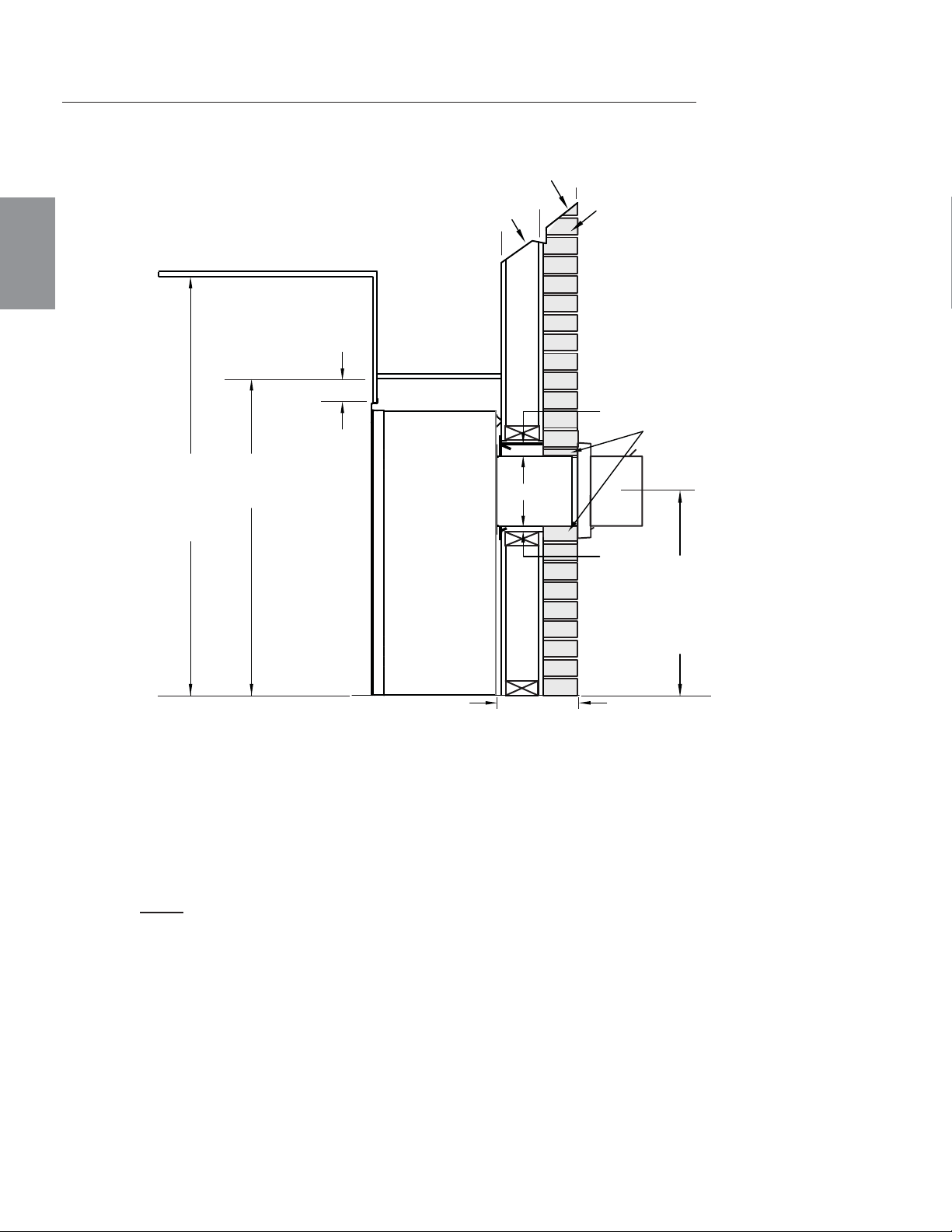
118
W415-1401 / C / 03.19.15
FR
COMBUSTIBLE
1"
[25mm]
3"
[76mm]
7"
[178mm]
41"
[1041mm]
1"-10"
[25mm-254mm]
ÉVENTS
54"
[1376mm]
PLAFOND
(MIN)
INCOMBUSTIBLE
0” (0MM) SI LES MATÉRIAUX
SONT INCOMBUSTIBLES,
COMME DE LA BRIQUE
ET DE LA PIERRE.
24"
[610mm]
MINIMUM
PLUS LA PENTE*
BRIQUE
B36 DÉGAGEMENTS MINIMAUX DE ÉVACUATION À L'ARRIÈRE
* Voir la section « ÉVACUATION »
ENCEINTE AVEC ÉVACUATION À L'ARRIÈRE
L'enceinte de l'appareil doit avoir une hauteur minimale de 41" (1041mm). Afi n de
respecter les contraintes de température, l’espace à l’intérieur de l’enceinte, autour de
l'appareil et au-dessus, doit demeurer sans obstruction.
NOTE: L'écran protection est télescopique et doivent être ajusté à protection
toute la profondeur de la pénétration de la paroi combustible.
Pour la ventilation arrière ne dépassement pas 10" (254mm) de section horizontale de ventilation.
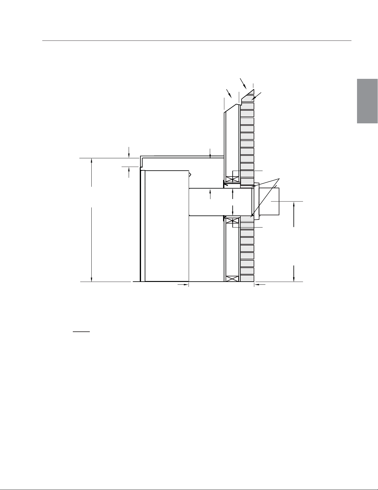
119
W415-1401 / C / 03.19.15
FR
COMBUSTIBLE
1"
[25mm]
3"
[76mm]
7"
[178mm]
41"
[1041mm]
10"-20"
[254mm-508mm]
ÉVENTS
11 1/2"
[368mm]
0” (0MM) SI LES MATÉRIAUX
SONT INCOMBUSTIBLES,
COMME DE LA BRIQUE
ET DE LA PIERRE.
INCOMBUSTIBLE
BRIQUE
24"
[610mm]
MINIMUM
PLUS LA PENTE*
B36 DÉGAGEMENTS MAXIMAUX DE ÉVACUATION À L'ARRIÈRE (EXEMPLE 1)
ENCEINTE AVEC ÉVACUATION À L'ARRIÈRE
L'enceinte de l'appareil doit avoir une hauteur minimale de 41" (1041mm). Afi n de
respecter les contraintes de température, l’espace à l’intérieur de l’enceinte, autour de
l'appareil et au-dessus, doit demeurer sans obstruction.
NOTE: L'écran protection est télescopique et doivent être ajusté à protection
toute la profondeur de la pénétration de la paroi combustible.
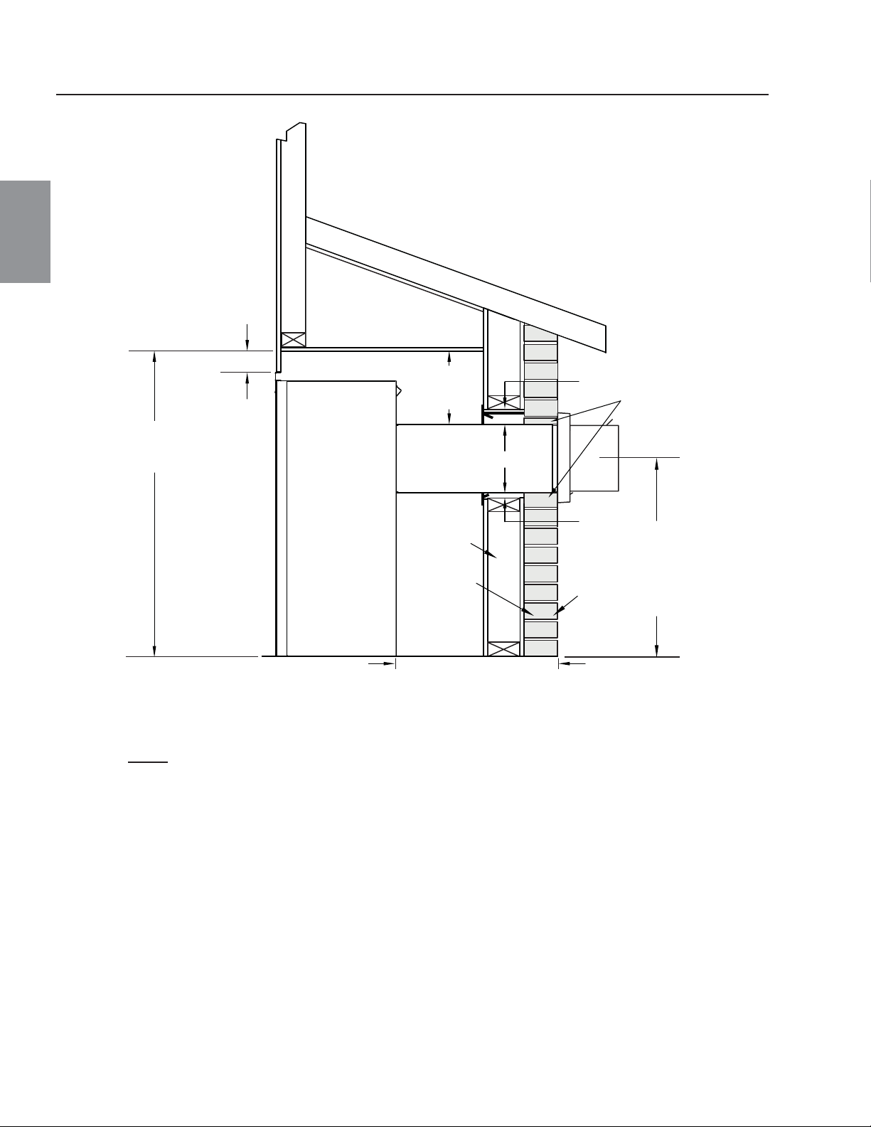
120
W415-1401 / C / 03.19.15
FR
INCOMBUSTIBLE
0” (0MM) SI LES
MATÉRIAUX SONT
INCOMBUSTIBLES,
COMME DE LA BRIQUE
ET DE LA PIERRE.
24"
[610mm]
MINIMUM
PLUS LA PENTE*
BRIQUE
10"-20"
[254mm-508mm]
ÉVENTS
COMBUSTIBLE
1"
[25mm]
3"
[76mm]
7"
[178mm]
41"
[1041mm]
11 1/2"
[292mm]
B36 DÉGAGEMENTS MAXIMAUX DE ÉVACUATION À L'ARRIÈRE (EXEMPLE 2)
ENCEINTE AVEC ÉVACUATION À L'ARRIÈRE
L'enceinte de l'appareil doit avoir une hauteur minimale de 41" (1041mm). Afi n de
respecter les contraintes de température, l’espace à l’intérieur de l’enceinte, autour de
l'appareil et au-dessus, doit demeurer sans obstruction.
NOTE: L'écran protection est télescopique et doivent être ajusté à protection
toute la profondeur de la pénétration de la paroi combustible.
!
AVERTISSEMENT
RISQUE D’INCENDIE!
AFIN D’ÉVITER LA POSSIBILITÉ QUE DE L’ISOLATION OU UN COUPE-VAPEUR ENTRENT EN CON-
TACT AVEC L’EXTÉRIEUR DU CAISSON, IL EST CONSEILLÉ D’INSTALLER L’APPAREIL CONTRE DES
MURS FINIS (C.-À-D. PANNEAU DE GYPSE) COMME TOUT AUTRE MUR DE LA MAISON. CECI
ASSURERA QUE LE DÉGAGEMENT AUX MATÉRIAUX COMBUSTIBLES EST MAINTENU.
NE FAITES PAS D’ENTAILLES À L’OSSATURE AUTOUR DES ESPACEURS. NE PAS MAINTENIR LES
DÉGAGEMENTS PEUT CAUSER UNE SURCHAUFFE ET UN INCENDIE. EMPÊCHEZ TOUT CONTACT
AVEC DE L'ISOLANT QUI S'AFFAISSE, AVEC L’OSSATURE OU AVEC TOUT AUTRE MATÉRIAU COM-
BUSTIBLE. BLOQUEZ L’ENTRÉE DE L’ENCEINTE POUR EMPÊCHER L'INFILTRATION D'ISOLANT
SOUFFLÉ. ASSUREZ-VOUS QUE L’ISOLATION ET LES AUTRES MATÉRIAUX SONT BIEN FIXÉS.
LORSQUE VOUS CONSTRUISEZ L’ENCEINTE, PRÉVOYEZ L’ÉPAISSEUR DES MATÉRIAUX DE
FINITION POUR MAINTENIR LES DÉGAGEMENTS. SI L’OSSATURE OU LES MATÉRIAUX DE FINITION
SE TROUVENT À UNE DISTANCE INFÉRIEURE À CELLE INDIQUÉE, ILS DOIVENT ÊTRE FAITS
ENTIÈREMENT DE MATÉRIAUX NON COMBUSTIBLES. LES MATÉRIAUX FAITS ENTIÈREMENT
D’ACIER, DE FER, DE BRIQUE, DE TUILE, DE BÉTON, D’ARDOISE, DE VERRE OU DE PLÂTRE, OU
D’UNE COMBINAISON DE CES MATÉRIAUX, SONT APPROPRIÉS. LES MATÉRIAUX RÉPONDANT À LA
NORME ASTM E 136, MÉTHODE DE TEST STANDARD DU COMPORTEMENT DES MATÉRIAUX DANS
UNE FOURNAISE AVEC TUBE VERTICAL À 1382° F (750°C), ET À LA NORME UL763 SONT
CONSIDÉRÉS COMME ÉTANT DES MATÉRIAUX NON COMBUSTIBLES.
AFIN D'ÉVITER UN RISQUE D'INCENDIE, LES DÉGAGEMENTS MINIMAUX AUX MATÉRIAUX
COMBUSTIBLES DOIVENT ÊTRE MAINTENUS.
L’ENCEINTE DE L’APPAREIL DOIT RESPECTER LA HAUTEUR MINIMALE REQUISE. MESUREZ À
PARTIR DE LA BASE DE L’APPAREIL.
SI DES ENSEMBLES DE MONTANTS EN ACIER AVEC PANNEAU DE CIMENT SONT FOURNIS, OU
SPÉCIFIÉ DANS LES INSTRUCTIONS D’INSTALLATION, ILS DOIVENT ÊTRE INSTALLÉS.
LES MATÉRIAUX DE FINITION DOIVENT ÊTRE NON COMBUSTIBLES PLACER ÉCLAT AVEC LA FACE
DE L’APPAREIL ÉTENDUE DU SOMMET DE L’APPAREIL COMME LE CONSEIL DE CIMENT, LE CAR-
REAU EN CERAMIQUE, LE MARBRE, ETC. NE PAS UTILISÉ DES BÛCHES OU LE CLOISON SECHE.
N'IMPORTE QUEL FEU A ÉVALUÉ DU CLOISON SÈCHE N'EST PAS ACCEPTABLE.
71.1B
121
W415-1401 / C / 03.19.15
FR
5.3 L'OSSATURE GX36
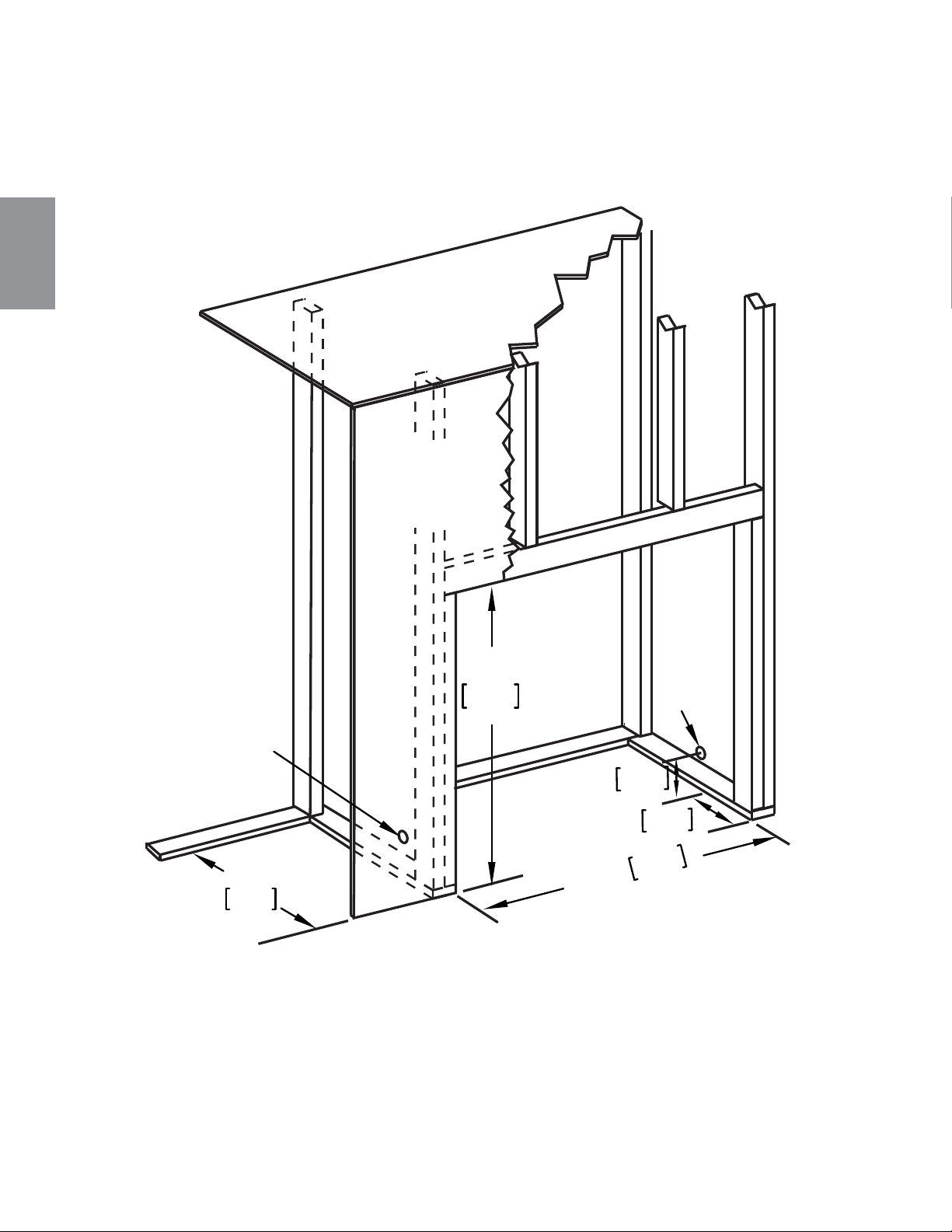
122
W415-1401 / C / 03.19.15
FR
5.3.1 DIMENSIONS MINIMALES DE L’OSSATURE GX36
35 1/2"
902mm
35"
889mm
1 7/8"
47mm
8"
203mm
16"
406mm
DESSUS
DE L’ENCEINTE
MATÉRIAU
DE FINITION
RACCORDEMENT
ÉLECTRIQUE
EMPLACEMENT
DE L’ENTRÉE
DU GAZ
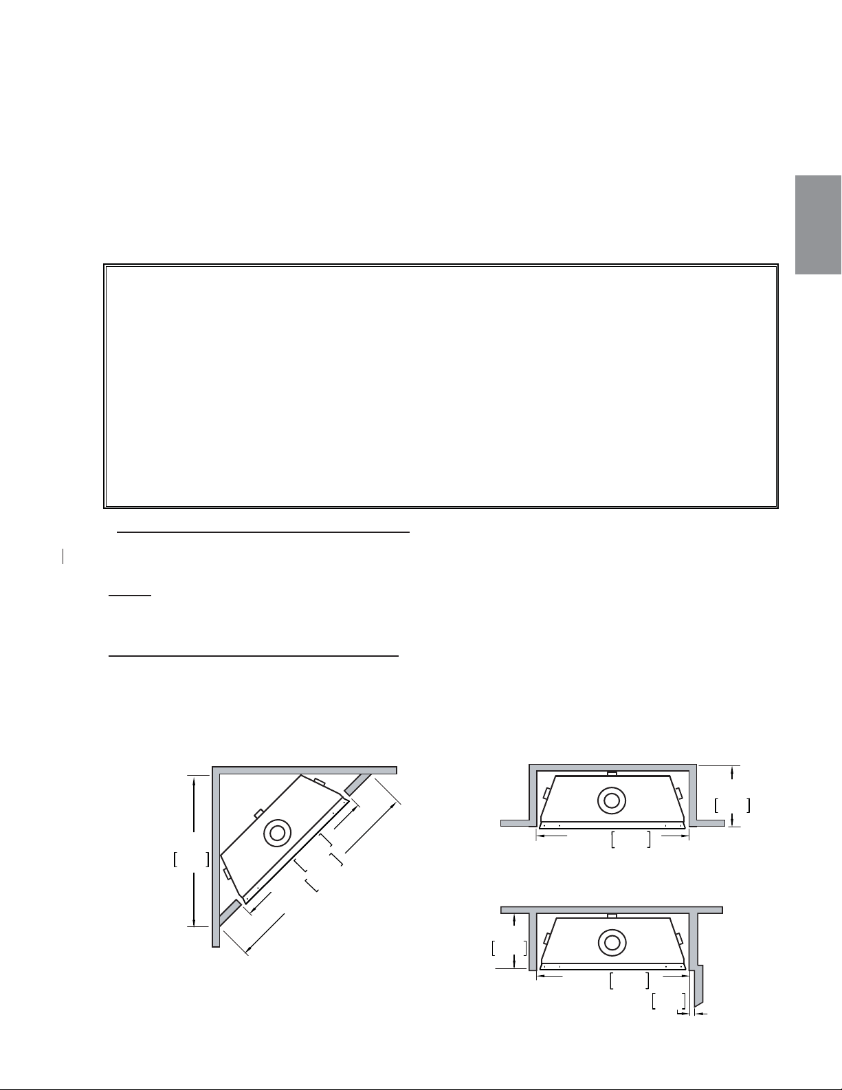
123
W415-1401 / C / 03.19.15
FR
Il est préférable de construire l'ossature après que l'appareil est en place et que le système d'évacuation est
installé. Construisez conformément aux exigences des codes du bâtiment locaux.
Il n'est pas nécessaire d'installer une base de protection avec ce type d'appareil.
Lorsque vous mettez l'appareil en place, surélevez-le de façon à prévoir l'épaisseur du plancher fi ni, c.-à-d.
tuiles, tapis ou bois franc, car s'ils n'ont pas été prévus, ils nuiront à l'ouverture de la porte d'accès inférieure et
à l'installation de plusieurs ensembles de contours.
Les matériaux combustibles peuvent être installés à égalité avec le devant de l'appareil, mais ils ne doivent
recouvrir aucune surface peinte en noir du devant de l'appareil. Les matériaux incombustibles (briques,
pierres, carreaux de céramique) peuvent empiéter sur la partie noire.
* SECTIONS D’ÉVENTS HORIZONTALES GX36: Un dégagement minimal aux matériaux combustibles de
1" (25mm) au-dessous et sur les côtés de l’évent et de 3" (76mm) au-dessus doit être maintenu sur toutes les
courses horizontales. Utilisez l’espaceur coupe-feu W010-3440 (fourni).
NOTE: Les dégagements minimaux entre le haut de l’évent et les matériaux combustibles peut être
réduite de 3" (76mm) à 2" (51mm) dans ces installations avec une event verticale de minimum 38"
(965mm) faite immédiatement au colet due l'appareil.
* SECTIONS D’ÉVENTS VERTICALES GX36: Un dégagement minimal aux matériaux combustibles de 1"
(25mm) est requis sur toutes les courses verticales à l’exception des dégagements à l’intérieur de l’enceinte
de l'appareil. Les course d'évents verticales dans le dégagements à l’intérieur doit être 3" (76mm) de
combustibles.Voir la section « DÉGAGEMENTS MINIMAUX DE L’ENCEINTE ». Utilisez l’espaceur coupe-feu
W500-0096 (non fourni).
Dégagements minimaux de l'appareil aux matériaux combustibles :
Ossature combustible :
- 0" aux espaceurs
- 1" (25mm) en dessous et sur les côtés du conduit d’évent*
- 3" (76mm) au-dessus du conduit d’évent*
Finition combustible :
- 0" à l’arrière
- 0" des côtés et du dessus en façade
Évacuation sur le dessus
- 50 1/2" (1283mm) du haut de l’enceinte jusqu’à la base de l’appareil
- 54" (1372mm) du plafond jusqu’à la base de l’appareil
Évacuatn sur l'arrière
- 42" (1067mm) du haut de l'enceinte jusqu' à la base de l'appareil
- 54" (1372mm) du plafond jusqu' à la base de l'appareil
-
35 1/2"
902mm
49 1/8"
1248mm
31 7/8"
810mm
ENCEINTE
INTÉRIEURE
ENCEINTE
EXTÉRIEURE
MURALE
CÔTÉ
16”
406mm
16"
406mm
2"
51mm
35 1/2"
902mm
35 1/2"
902mm
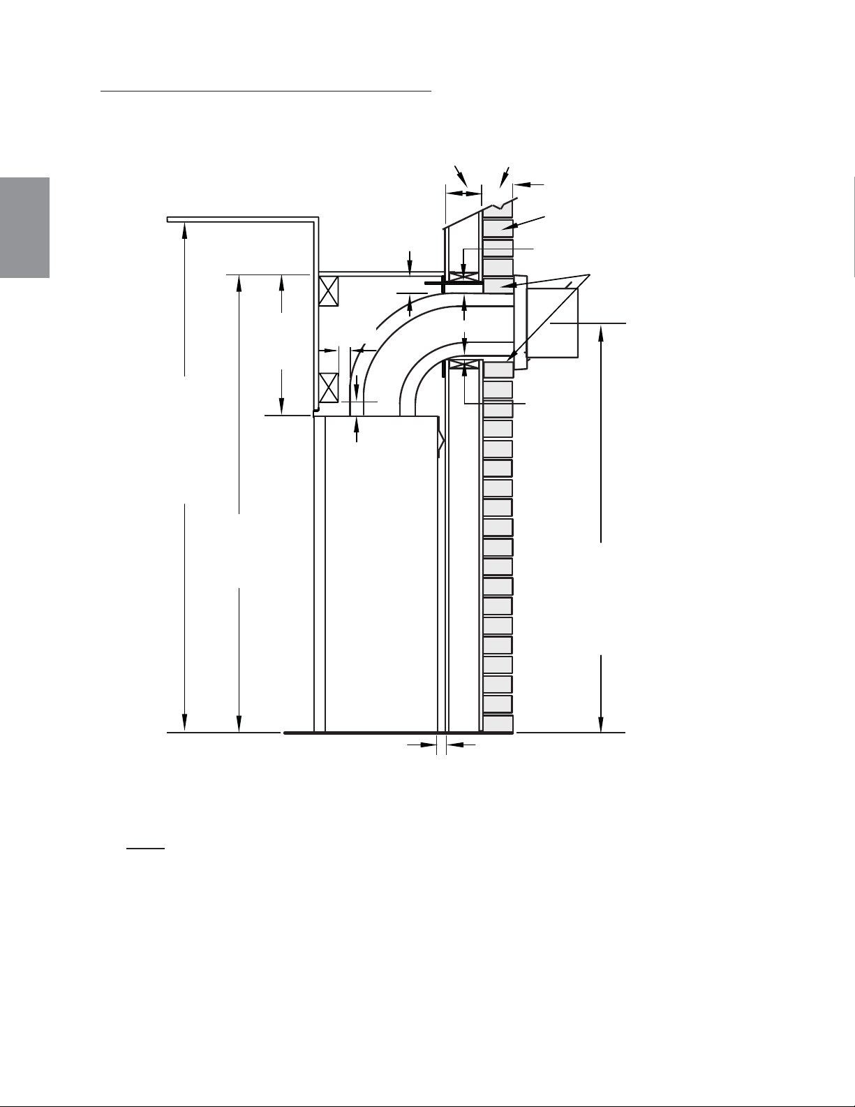
124
W415-1401 / C / 03.19.15
FR
3" [76mm]
COMBUSTIBLE
3" [76mm]
MINIMUM
3" [76mm]
2"
[51mm]
1"
[25mm]
50 1/2"
[1283mm]
16 1/4"
[412mm]
1"
[25mm]
INCOMBUSTIBLE
BRIQUE
0” (0MM) SI LES MATÉRIAUX
SONT INCOMBUSTIBLES,
COMME DE LA BRIQUE
ET DE LA PIERRE.
54"
[1372mm]
PLAFOND
(MIN)
42 1/16"
[1068mm]
MINIMUM
PLUS LA PENTE*
ENCEINTE AVEC ÉVACUATION SUR LE DESSUS
L'enceinte de l'appareil doit avoir une hauteur minimale de 50 1/2" (1283mm). Afi n de respecter les
contraintes de température, l’espace à l’intérieur de l’enceinte, autour de l'appareil et au-dessus,
doit demeurer sans obstruction.
GX36 ÉVACUATION SUR LE DESSUS
NOTE: L'écran protection est télescopique et doivent être ajusté à protection
toute la profondeur de la pénétration de la paroi combustible.
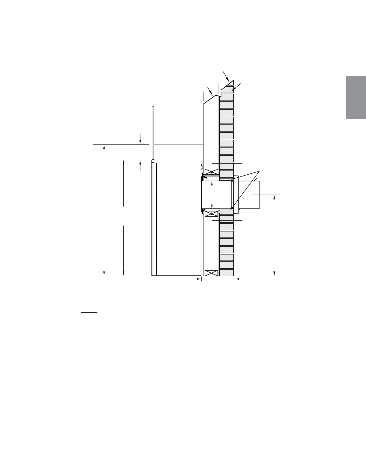
125
W415-1401 / C / 03.19.15
FR
INCOMBUSTIBLE
0” (0MM) SI LES MATÉRIAUX
SONT INCOMBUSTIBLES,
COMME DE LA BRIQUE
ET DE LA PIERRE.
24"
[610mm]
MINIMUM
PLUS LA PENTE*
BRIQUE
COMBUSTIBLE
1"
[25mm]
3"
[76mm]
10"
[254mm]
44"
[1118mm]
1"-10"
[25mm-254mm]
ÉVENTS
34 1/16"
[865mm]
* Voir la section « ÉVACUATION »
ENCEINTE AVEC ÉVACUATION À L'ARRIÈRE
L'enceinte de l'appareil doit avoir une hauteur minimale de 44" (1118mm). Afi n de
respecter les contraintes de température, l’espace à l’intérieur de l’enceinte, autour de
l'appareil et au-dessus, doit demeurer sans obstruction.
Pour la ventilation arrière ne dépassement pas 10" (254mm) de section horizontale de ventilation.
GX36 DÉGAGEMENTS MINIMAUX DE ÉVACUATION À L'ARRIÈRE
NOTE: L'écran protection est télescopique et doivent être ajusté à protection
toute la profondeur de la pénétration de la paroi combustible.
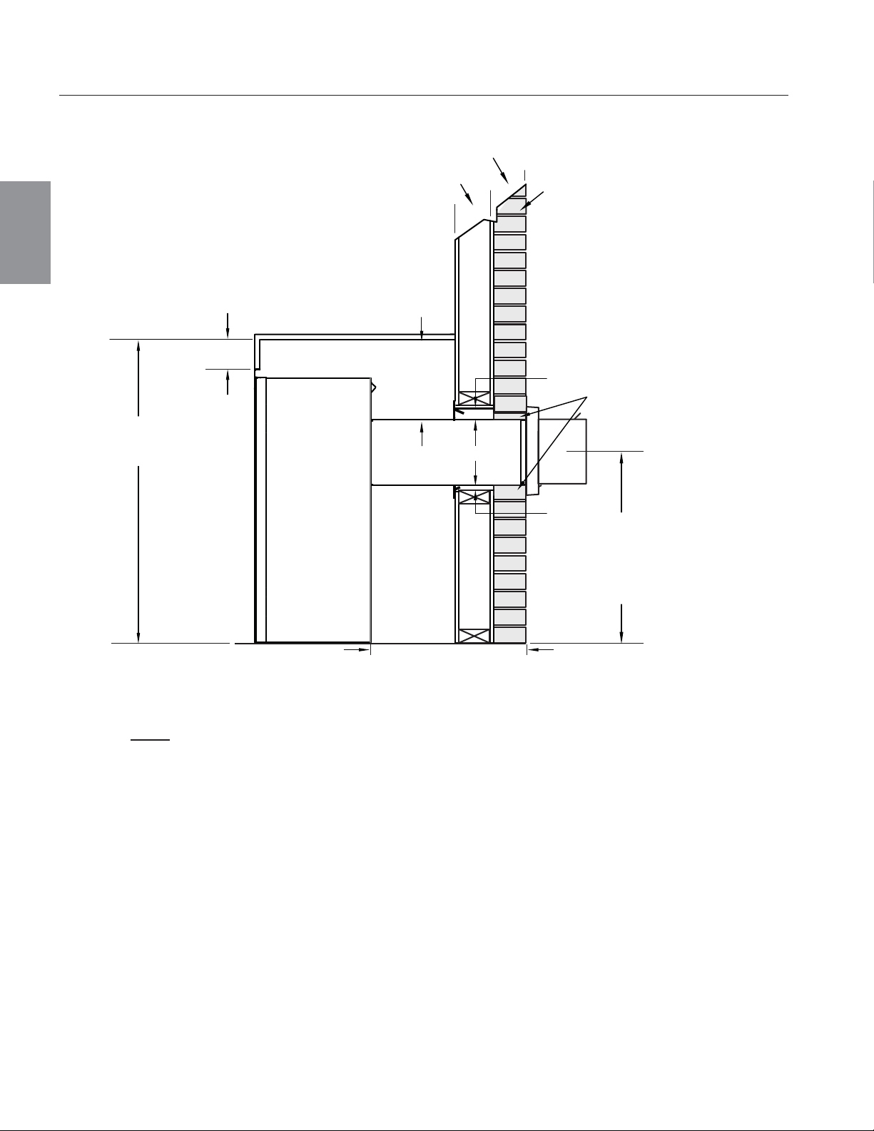
126
W415-1401 / C / 03.19.15
FR
0” (0MM) SI LES MATÉRIAUX
SONT INCOMBUSTIBLES,
COMME DE LA BRIQUE
ET DE LA PIERRE.
INCOMBUSTIBLE
BRIQUE
24"
[610mm]
MINIMUM
PLUS LA PENTE*
COMBUSTIBLE
1"
[25mm]
3"
[76mm]
10"
[254mm]
44"
[1118mm]
10"-20"
[254mm-508mm]
ÉVENTS
14 1/2"
[368mm]
ENCEINTE AVEC ÉVACUATION À L'ARRIÈRE
L'enceinte de l'appareil doit avoir une hauteur minimale de 44" (1118mm). Afi n de
respecter les contraintes de température, l’espace à l’intérieur de l’enceinte, autour de
l'appareil et au-dessus, doit demeurer sans obstruction.
GX36 DÉGAGEMENTS MAXIMAUX DE ÉVACUATION À L'ARRIÈRE (EXEMPLE 1)
NOTE: L'écran protection est télescopique et doivent être ajusté à protection
toute la profondeur de la pénétration de la paroi combustible.
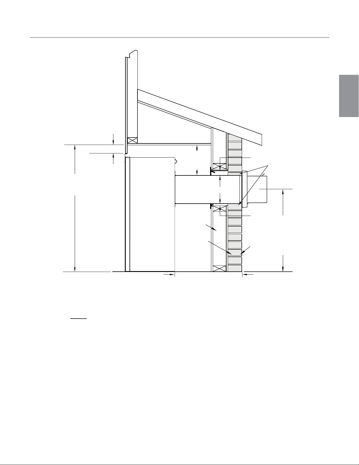
127
W415-1401 / C / 03.19.15
FR
GX36 DÉGAGEMENTS MAXIMAUX DE ÉVACUATION À L'ARRIÈRE (EXEMPLE 2)
INCOMBUSTIBLE
0” (0MM) SI LES
MATÉRIAUX SONT
INCOMBUSTIBLES,
COMME DE LA BRIQUE
ET DE LA PIERRE.
24"
[610mm]
MINIMUM
PLUS LA PENTE*
BRIQUE
10"-20"
[254mm-508mm]
ÉVENTS
COMBUSTIBLE
1"
[25mm]
3"
[76mm]
10"
[254mm]
44"
[1118mm]
14 1/2"
[368mm]
ENCEINTE AVEC ÉVACUATION À L'ARRIÈRE
L'enceinte de l'appareil doit avoir une hauteur minimale de 44" (1118mm). Afi n de
respecter les contraintes de température, l’espace à l’intérieur de l’enceinte, autour de
l'appareil et au-dessus, doit demeurer sans obstruction.
NOTE: L'écran protection est télescopique et doivent être ajusté à protection
toute la profondeur de la pénétration de la paroi combustible.

128
W415-1401 / C / 03.19.15
FR
APPAREIL
ZONE
ENCASTRÉE
OU ALCÔVE
NOTE : Les zones encastrées ou les alcôves au dessus de l'appareil peuvent être aussi profondes que désiré
tant que les dégagements minimaux aux matériaux combustibles sont respectés.
Vous pouvez utiliser un matériau incombustible, pourvu que les dégagements minimaux aux matériaux
combustibles soient appliqués.
Le volume minimal de l'enceinte doit être augmenté d'au moins la valeur du volume de la zone encastrée. Cet
ajustement peut être réalisé en augmentant une ou toutes les dimensions de l'enceinte.
71.2
ZONE
ENCEINTE
5.4 INSTALLATION EN ALCÔVE
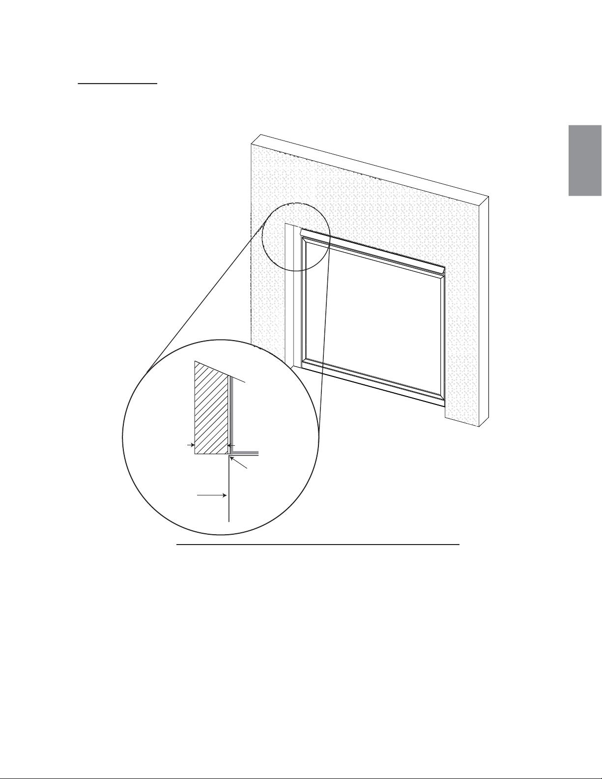
AVERTISSEMENT: Les matériaux de finition incombustibles ne doivent pas dépasser de plus 4” (101,6mm) la façade de la
porte (sur toutes côtés). Si des projections plus grandes sont requises, augmentez les dégagements des côtés et du dessus
de 2"
(50,8mm) pour chaque pouce (24,5mm) supplémentaire de projection. Si vous utilisez un moulure optionelle, les
même règles s'applique, commençant du sommet du moulure. Garantir que les dégagements sont maintenus
pour l'enlèvement du moulure, vous devez l'enlever de l'appareil pour l'entretien.
71.7
4" (102mm)
VITRE DE
PORTE
SOMMET DE
L’APPAREIL
129
W415-1401 / C / 03.19.15
FR
5.5 MATÉRIAU DE FINITION INCOMBUSTIBLE
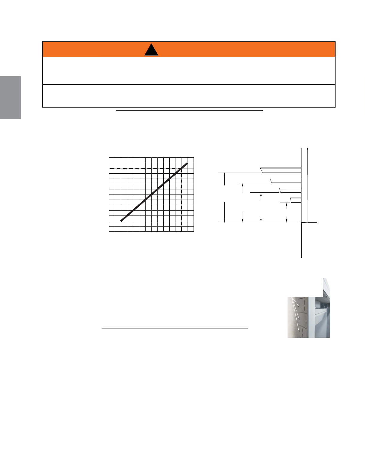
!
AVERTISSEMENT
RISQUE D’INCENDIE. CONSERVEZ TOUS LES DÉGAGEMENTS AUX MATÉRIAUX COMBUSTIBLES
SPÉCIFIÉS. NE PAS RESPECTER CES INSTRUCTIONS PEUT CAUSER UN INCENDIE OU UNE
SURCHAUFFE. ASSUREZ-VOUS QUE TOUS LES DÉGAGEMENTS (ARRIÈRE, CÔTÉS, DESSUS,
ÉVENTS, TABLETTE, FAÇADE, ETC.) SONT RESPECTÉS À LA LETTRE.
LORSQUE VOUS UTILISEZ DE LA PEINTURE OU DU VERNIS COMME FINITION POUR VOTRE
TABLETTE, ASSUREZ-VOUS QU’ILS SOIENT RÉSISTANTS À LA CHALEUR AFIN DE
PRÉVENIR LA DÉCOLORATION.
73.1
55.2
A. Afi n de déterminer l’emplacement défi nitif des supports de fi xation, vous
devez d’abord calculer l’épaisseur des matériaux de fi nition (p. ex. panneau
de gypse). Ceci permettra de calculer les dimensions à partir de la face du
caisson extérieur jusqu’aux supports de fi xation. Une fois que vous avez
déterminé l’emplacement défi nitif, fi xez à l’aide d’une vis auto-perceuse*.
SUPPORT DE
FIXATION
130
W415-1401 / C / 03.19.15
FR
Le dégagement d'une tablette combustible à l'appareil peut varier selon la profondeur
de la tablette. Utilisez le graphique pour vous aider à déterminer le dégagement
nécessaire. Les mêmes dégagements aux matériaux combustibles s'appliquent
pour toutes les surfaces en projection sur les côtés de l'appareil.
5.6 DÉGAGEMENTS MINIMAUX DE LA TABLETTE
5.7 INSTALLATION SUPPORT DE FIXATION
+
$
8
7
(
8
5
'
(
/
$
7
$
%
/
(
7
7
(
(")
DESSUS DE L'APPAREIL
8" [203mm]
8"
[203mm]
6"
[152mm]
4"
[102mm]
2" [51mm]
2" [51mm]
4" [102mm]
6" [152mm]
TABLETTE
PROJECTION DE LA TABLETTE (")
2" (51mm)
24681012
4" (102mm)
6" (152mm)
10" (254mm)
12" (305mm)
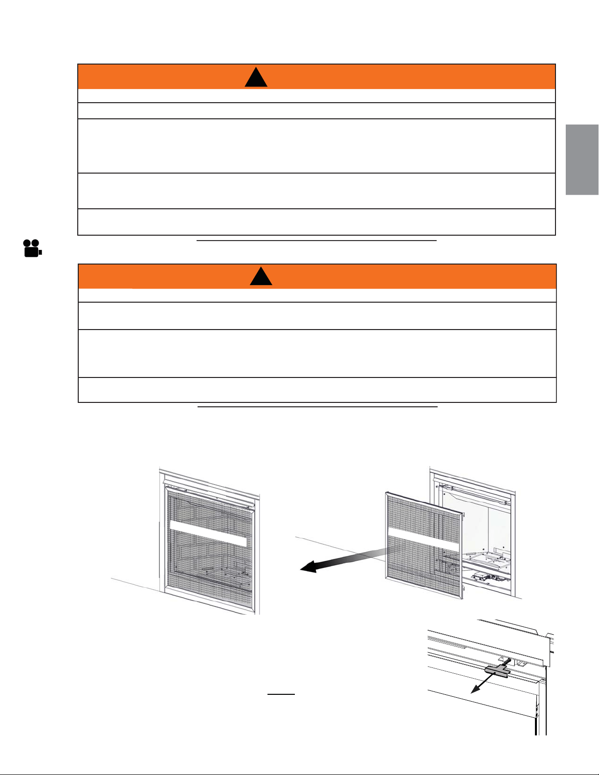
!
AVERTISSEMENT
RISQUE D’INCENDIE!
N’OBSTRUEZ JAMAIS L’OUVERTURE SUR LE DEVANT DE L’APPAREIL.
LA FAÇADE DE L’APPAREIL DOIT ÊTRE FAITE DE MATÉRIAUX INCOMBUSTIBLES COMME DE LA
BRIQUE, DU MARBRE, DU GRANITE, ETC., À CONDITION QUE CES MATÉRIAUX NE SE TROUVENT
PAS EN DEÇÀ DE LA DIMENSION SPÉCIFIÉE TEL QU’ILLUSTRÉ. COMME ALTERNATIVE, VOUS
POUVEZ UTILISER LE PANNEAU DE GYPSE COMME FINITION POUR VOTRE APPAREIL, VOIR LES
ILLUSTRATIONS À SUIVRE.
NE FRAPPEZ PAS, NE CLAQUEZ PAS ET N’ÉGRATIGNEZ PAS LA PORTE VITRÉE. NE FAITES PAS
FONCTIONNER L’APPAREIL LORSQUE LA PORTE VITRÉE EST ENLEVÉE, FISSURÉE, BRISÉE OU
ÉGRATIGNÉE.
LES MATÉRIAUX DE FAÇADE OU DE FINITION NE DOIVENT JAMAIS EMPIÉTER SUR L’OUVERTURE
DE L’APPAREIL.
72.1A
!
AVERTISSEMENT
LA VITRE PEUT ÊTRE CHAUDE, NE TOUCHEZ PAS LA VITRE JUSQU’À CE QU’ELLE AIT REFROIDI.
LES LOQUETS DE PORTE FONT PARTIE D'UN DISPOSITIF DE SÉCURITÉ ET DOIVENT ÊTRE ADÉQUATEMENT
VERROUILLÉS. NE FAITES PAS FONCTIONNER L’APPAREIL LORSQUE LES LOQUETS SONT DÉVERROUILLÉS.
LES MATÉRIAUX DE FAÇADE ET DE FINITION NE DOIVENT PAS NUIRE À LA CIRCULATION DE L'AIR DANS LES
OUVERTURES D'AIR ET LES PERSIENNES, NI AU FONCTIONNEMENT DES PERSIENNES OU DES PORTES. ILS
NE DOIVENT PAS NON PLUS ENTRAVER L'ACCÈS POUR L'ENTRETIEN. RESPECTEZ TOUS LES DÉGAGEMENTS
AUX MATÉRIAUX COMBUSTIBLES.
AVANT D’ENLEVER LA PORTE, ÉTEIGNEZ L’APPAREIL ET ATTENDEZ QUE CE DERNIER SOIT FROID AU
TOUCHER. LES PORTES SONT LOURDES ET FRAGILES; MANIPULEZ AVEC SOIN.
75.1
131
W415-1401 / C / 03.19.15
FR
6.0 FINITIONS
6.1 OUVERTURE ET FERMETURE DE LA PORTE ET L'ÉCRAN DE PROTECTION
Une barrière conçu à réduire le risque de brûlures à partir de le chaude la vitre est à condition que
avec l’appareil et sera être installés.
Avant d’enlever la porte vitrée, l’écran de protection doit être enlever. Soulevez l’écran de protection hors des
4 goupilles et enlever de l’appareil, puis inclinez la partie haut du porte vitrée puis enlever de l'appareil.
Laissez une main sur la porte vitrée pendant l'enlèvement de la porte. La porte
vitrée est maintenue en place par deux loquets située en haut et deux loquets
en bas de la porte. Tirez les poignées des loquets vers l’avant, puis retirez
les loquets du cadre de porte afi n de libérer le haut de la porte. Répétez la
même opération pour les deux loquets inférieures. Pivotez ensuite le haut de
la porte vers l’avant jusqu’à ce que vous puissiez saisir les côtés. Soulevez la
porte hors du dispositif de retenu inférieur. NOTE: Ces système de décharge
constituent le système de secours de printemps de l'appareil. Vérifi ez si le
système de décharge effectue effi cacement.
Inversez ces étapes pour réinstaller la porte et l'écran de protection. Assurez la
ecran de protection est correctement installé.
L
'ÉCRAN D
E PROTECTION
SAFETY SCREEN
L
'
ÉCRAN DE PROT
E
CTION
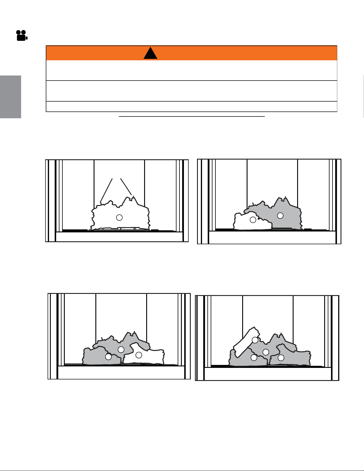
!
AVERTISSEMENT
OMETTRE DE POSITIONNER LES BÛCHES CONFORMÉMENT AUX SCHÉMAS OU OMETTRE
D’UTILISER UNIQUEMENT DES BÛCHES SPÉCIFIQUEMENT APPROUVÉES POUR CET APPAREIL
PEUT CAUSER DES DOMMAGES MATÉRIELS OU DES BLESSURES CORPORELLES.
LES BÛCHES DOIVENT ÊTRE PLACÉES CORRECTEMENT À L’INTÉRIEUR DE L’APPAREIL. NE CHANGEZ PAS LA
POSITION DES BÛCHES CAR L’APPAREIL RISQUE DE NE PAS FONCTIONNER ADÉQUATEMENT ET UN RETARD
D’ALLUMAGE RISQUE DE SE PRODUIRE.
LES BÛCHES SONT FRAGILES ET DEVRAIENT ÊTRE MANIPULÉES AVEC SOIN.
76.1A
132
W415-1401 / C / 03.19.15
FR
6.2 DISPOSITION DES BÛCHES
Les bûches PHAZER
MD
et les braises incandescentes, exclusives aux appareils Napoléon, créent un effet incan-
descent réaliste et unique qui est différent dans chaque installation. Prenez le temps de bien installer les braises
incandescentes pour obtenir le meilleur effet possible. La couleur des bûches peut varier. Lors de la première uti-
lisation de l'appareil, les couleurs deviendront plus uniformes à mesure que leurs pigments seront « absorbés »
pendant le procédé de « cuisson ».
C. Placez la bûche droite (W135-0577) sur les
deux goujons aux côté droite du support.
D. Placez la bûche croisé gauche (W135-0578)
sur l’épingle gauche du bûche arrière, il
devrait se reposer sur l’encoche du bûche
gauche.
A. Placez la bûche arrière (W135-0575)
fermement sur les deux goujons à l’arrière
du support. Assurez-vous que la bûche
repose à plat et ne couvre pas l’ouverture
du veilleuse. Placez les deux épingles dans
les trous de la bûche arrière.
B. Placez la bûche gauche (W135-0576) sur les
deux goujons aux côté gauche du support.
B
A
A
ÉPINGLES
B
A
C
B
A
C
D
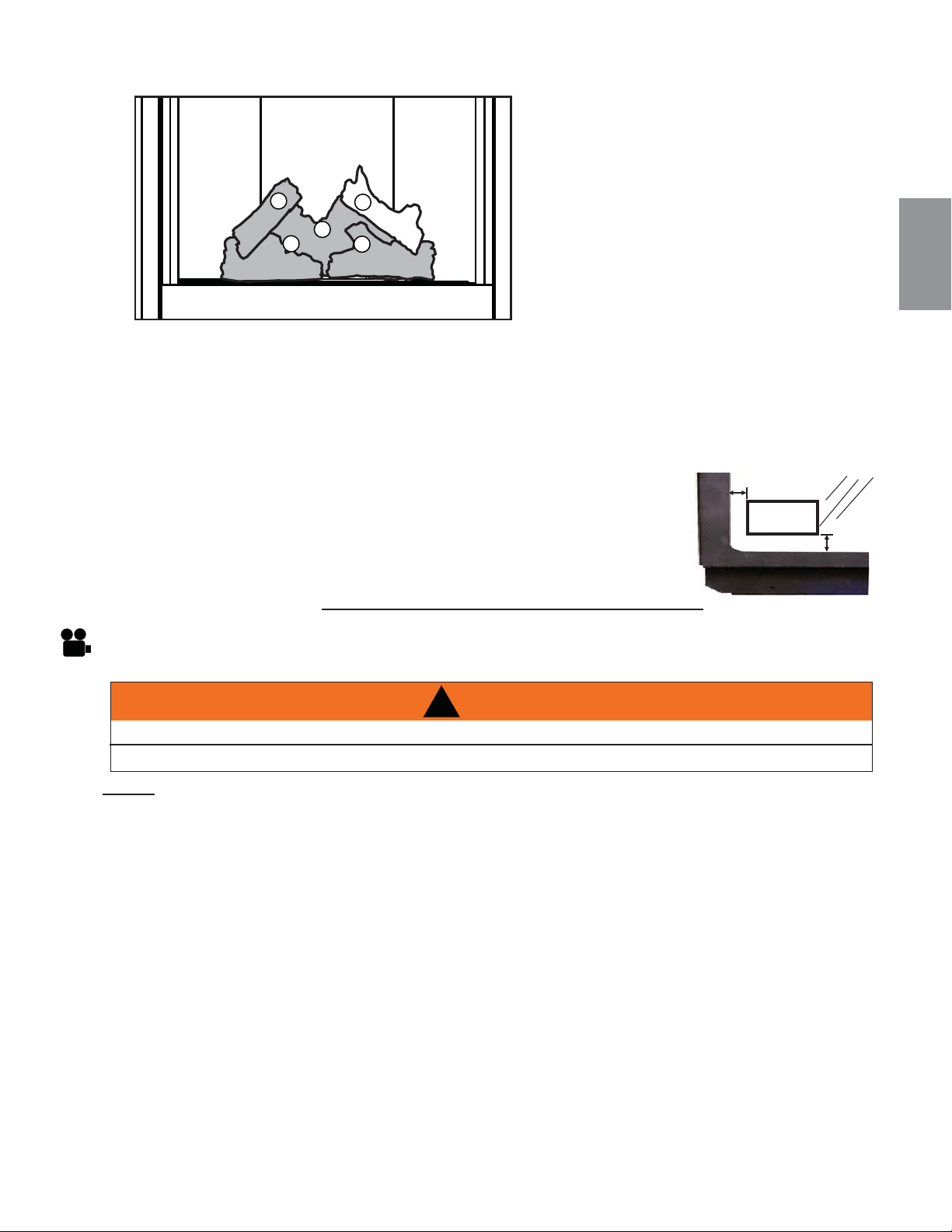
NOTE: En cas d’une panne de courrant votre appareil peut fonctionner utilisant le sauvegarde de pile
fourni.
A. Ouvrez le gaz et l'électricité hors de l'appareil, avant de commencer l'installation.
B. Trouver votre sauvegarde de pile, fourni aux sac du manuel.
C. Installez 4 piles AA (non fourni) dans le bloc-piles du boîtier fourni, notez la polarité des piles puis
insérez-les comme indiqué sur le couvercle (+/-). (Pour ouvrir le boîtier de batterie glisser le piece de
l’arrière hors du boîtier de batterie).
D. Enlever l’écran de protection en le levant vers le haut hors des quatre vis d’épaulement.
E. Attacher les fi ls étiqueté "PILE" à partir de harnais de fi ls de l’appareil aux boîtier de batterie.
F. Placez le boîtier de batterie dans la compartiment du soupape au-dessous du brûleur, garantir que le
boîtier de batterie est placer dans un endroit proper facilement.
G. Garantir que l’écran de protection soit reinstallez pendant l’opération de l’appareil.
H. Ouvrir l’alimentation de gaz et l’alimentation électrique pour fonctionner l’appareil.
!
WARNING
COUPEZ L’ALIMENTATION EN GAZ ET L’ALIMENTATION ÉLECTRIQUE DE L’APPAREIL
L’APPAREIL PEUT ÊTRE, NE TOUCHEZ PAS L’APPAREIL JUSQU’À CE QU’ELLE AIT REFROIDI.
133
W415-1401 / C / 03.19.15
FR
6.3 MISE EN PLACE DU LOGO
97.1A
Retirez le papier dorsal du logo et placez-le sur la porte vitrée tel qu’indiqué.
LOGO
½"(12,7mm)
½"(12,7mm)
E. Placez la bûche croisé droite (W135-0547)
en place par alignez les trous en bas de la
bûche avec les deux tiges située dans la
bûche droite et aux côté droite de la bûche
inférieure.
G. Installez la porte et l’écran de protection.
B
A
C
D
E
6.4 D’INSTALLATION DU SAUVEGARDE DE PILE
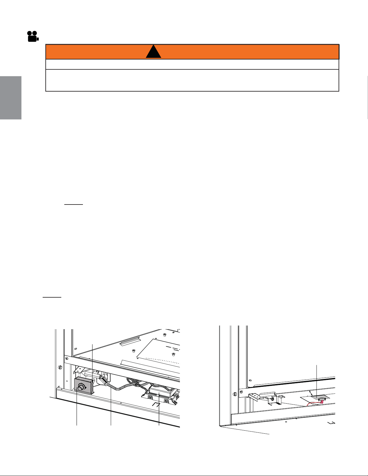
134
W415-1401 / C / 03.19.15
FR
!
AVERTISSEMENT
ASSUREZ-VOUS QUE L’APPAREIL EST COMPLÈTEMENT REFROIDI AVANT DE COMMENCER L’INSTALLATION.
AFIN D’ÉVITER LES RISQUES DE SUFFOCATION, GARDEZ LE SAC D’EMBALLAGE LOIN DES BÉBÉS ET DES
JEUNES ENFANTS. NE LE LAISSEZ PAS TRAÎNER DANS LES BERCEAUX, LES LITS, LES POUSSETTES OU LES
PARCS DE JEU. CE SAC N’EST PAS UN JOUET. NOUEZ-LE AVANT DE LE JETER.
A. Soulevez le pare-étincelles et enlevez-le de l’appareil, référer la section, "OUVERTURE ET
FERMETURE DE L'ÉCRAN DE PROTECTION ET LA PORTE".
B. Enlevez la porte de l’appareil en dégageant les quatre loquets.
C. Débranchez le transformateur du module de commande. Soulevez le module de commande du bas
de l’appareil, puis déplacez le module et le transformateur sur le côté pour faciliter l’installation de la
souffl erie.
D. Enlevez les deux bandes adhésives à l’arrière des bandes en Velcro qui se trouvent sur le support de
montage de la souffl erie.
E. Branchez les deux connecteurs de ¼’’ (noir et blanc) du harnais de fi ls à la souffl erie.
F. Branchez les deux connecteurs de ¼’’ (noir et rouge) du harnais de fi ls à la souffl erie.
G. Faites pivoter la souffl erie dans le bas de l’appareil et centrez-la sur la paroi arrière du caisson extérieur.
Pressez fermement la souffl erie contre le caisson extérieur pour que l’adhésif colle bien à l’appareil.
NOTE: VEILLEZ À CE QUE TOUS LES FILS RESTENT ÉLOIGNÉS DE LA SOUFFLERIE.
H. Remettez le module de commande dans sa position originale. Assurez-vous que le transformateur est
branché dans la prise arrière de la boîte électrique, comme indiqué à la Figure 1.
I. Enlevez la bande adhésive à l’arrière de la bande en Velcro qui se trouve sur l’interrupteur à vitesse
variable (IVV). Mettez l’IVV bien en place dans le coin avant gauche de la base du caisson extérieur,
comme indiqué à Figure 1. Branchez le connecteur de l’IVV dans la prise correspondante du harnais de
fi ls.
J. Placez le support aimanté du thermodisque sur la base de la chambre de combustion environ à 4”
(101,6 mm) du devant de l’appareil, comme indiqué à la Figure 2. Veillez à ce que le harnais de fi ls soit
bien fi xé.
K. Branchez le cordon d’alimentation de la souffl erie dans la boîte électrique, comme indiqué à la Figure 1.
NOTE: La souffl erie est actionnée par la chaleur. Lorsqu’elle est mise sous tension, elle se met
automatiquement en marche environ 15 minutes après l’allumage de l’appareil et fonctionnera environ
30 minutes après l’arrêt de l’appareil.
SUPPORT DU
THERMODISQUE
4” (101.6mm)
FIGURE 2FIGURE 1
6.5 D’INSTALLATION DU SOUFFLERIE
INTERRUPTEUR
À VITESSE
VARIABLE
CORDON
D’ALIMENTATION
DE LA SOUFFLERIE
MODULE DE
COMMANDE
BOÎTIER
ÉLECTRIQUE
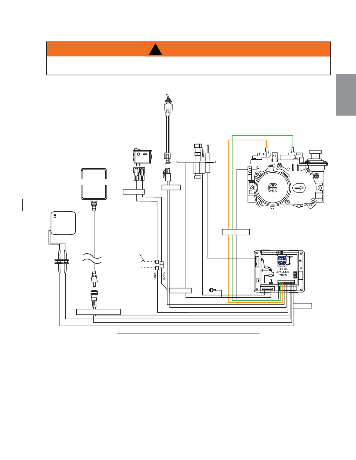
135
W415-1401 / C / 03.19.15
FR
6.6 SCHÉMA DE CÂBLAGE
(OPTIONNEL)
69.7
BOÎTIER DE
PILES
(FOURNI AUX SAC
DU MANUEL)
TERRE
DFC
SOUPAPE
ON / OFF
IPI / CPI
ALIMENTATION CC
OFF ON
ORANGE
VERT
CARTE DE
CIRCUITS
IMPRIMÉS IPI
SOUPAPE
ÉLECTRONIQUE
ANNEAU
DE MISE À
LA TERRE
INTERRUPTER
(ACS/IPI)
Débranchez ces
connecteurs de
l’interrupteur marche/arrêt
pour les connecter au
thermostat optionnel
TRANSFORMATEUR
TÉLÉCOMMANDE
ON / OFF
Cette appareil est fourni avec une sauvegarde de pile. Si la sauvegarde est utilisé, installez 4 piles “AA”
(non-fourni) dans la boîtier de piles et connectez au harnais de fi l.
!
AVERTISSEMENT
NE RACCORDEZ PAS L’INTERRUPTEUR MURAL OU LA SOUPAPE DE GAZ À L’ALIMENTATION ÉLECTRIQUE
(110 VOLTS).
BOîTIER DE
PILES
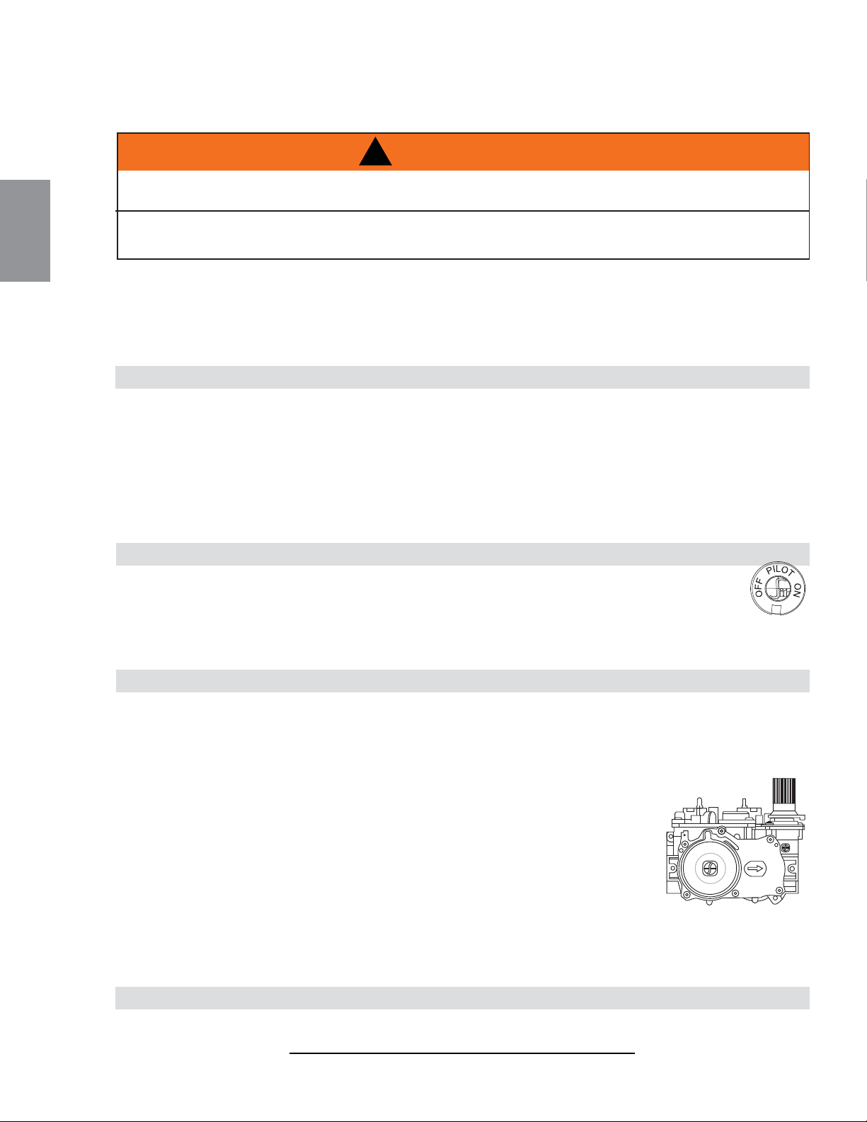
7.1 B36NTRE/GX36NTRE & B36PTRE/GX36PTRE (ELECTRONIQUE)
136
W415-1401 / C / 03.19.15
FR
7.0 FONCTIONNEMENT
A
ssurez-vous que l’arrivée de gaz au brûleur est continue avant d’installer la porte. Lorsqu’il est allumé pour la première
fois, ce foyer dégagera une légère odeur pendant quelques heures. Cela est une condition normale temporaire causée par
le conditionnement des bûches et l’évaporation des peintures et lubrifi ants internes utilisés dans le processus de fabrica-
tion; elle ne se reproduira plus. Après de longues périodes sans utiliser le foyer, comme à la suite de vacances ou à la fi n
de l’été, il se peut qu’une légère odeur se dégage pendant quelques heures. Ceci est causé par des particules de pous-
sière brûlant dans l’échangeur de chaleur. Dans les deux cas, ouvrez une fenêtre pour aérer la pièce.
POUR VOTRE SÉCURITÉ, LISEZ CE QUI SUIT AVANT D’ALLUMER
A. Ne pas allumer si des enfants ou d’autres individus à risque sont à proximité du foyer.
B. Cet appareil est muni d’une veilleuse qui doit être allumée manuellement tout en suivant ces instructions à la lettre.
C. Avant d’allumer, sentez autour de l’appareil et près du plancher afi n de vous assurer qu’il n’y a pas de fuite de gaz.
Certains gaz sont plus lourds que l’air et se déposeront au niveau du plancher.
D. N’utilisez que votre main pour tourner le bouton de contrôle du gaz. N’utilisez jamais d’outils. Si le bouton ne tourne
pas manuellement, n’essayez pas de le réparer. Appelez un technicien qualifi é. Forcer le bouton ou tenter de réparer le
mécanisme pourrait causer un feu ou une explosion.
E. N’utilisez pas ce foyer si une partie quelconque a été submergée. Contactez immédiatement un technicien qualifi é pour
l’inspecter et pour remplacer toute pièce du système de contrôle et du contrôle du gaz qui aurait été submergée.
QUE FAIRE SI VOUS DÉTECTEZ UNE ODEUR DE GAZ
• Coupez l’alimentation en gaz au foyer.
• Ouvrez les fenêtres.
• N’allumez aucun appareil.
• Ne touchez à aucun interrupteur électrique;
n’utilisez aucun téléphone dans votre immeuble.
• De la maison d’un voisin, appelez im-
médiatement votre fournisseur de gaz
et suivez ses instructions.
• Si vous ne pouvez pas rejoindre votre
fournisseur de gaz, appelez le service
des incendies.
INSTRUCTIONS D’ALLUMAGE
1. Arrêtez! Lisez les consignes de sécurité ci-dessus.
2. Enlevez les piles de l’émetteur.
3. Coupez l’alimentation électrique à l’appareil.
4. Cet appareil est équipé d’un dispositif d’allumage qui allume automatiquement la veilleuse. N’essayez pas
de l’allumer manuellement.
5. Enlevez la porte vitrée.
6. Tournez la soupape de sectionnement manuelle dans le sens horaire à « OFF ». Elle
est située derrière le panneau d’accès.
7. Attendez cinq (5) minutes pour que le gaz puisse s’échapper. Si vous détectez une
odeur de gaz, y compris au niveau du plancher, ARRÊTEZ! et suivez les instructions
ci-dessus « Que faire si vous détectez une odeur de gaz ». Continuez à l’étape suiv-
ante si vous ne sentez pas de gaz.
8. Tournez la soupape de sectionnement manuelle dans le sens antihoraire à « ON ».
9. Remettez en place la porte vitrée.
10. Rétablissez l’alimentation électrique au foyer et remettez les piles dans la télécommande.
11. Appuyez sur le bouton « ON » de la télécommande. Vous devriez entendre un bip du récepteur pour confi rm-
er la communication (consultez la section « Fonctionnement du foyer » pour l’activation de la télécommande).
1. Coupez l’alimentation électrique au foyer si un travail d’entretien doit se faire.
2. Enfoncez légèrement le bouton de contrôle du gaz et tournez vers la droite à « OFF ». Ne forcez pas.
INSTRUCTIONS POUR COUPER LE GAZ
GAS KNOB
47.3A
SI CES INSTRUCTIONS NE SONT PAS SUIVIES À LA LETTRE, UN INCENDIE OU UNE EXPLOSION POURRAIENT
S’ENSUIVRE, CAUSANT DES DOMMAGES MATÉRIELS,DES BLESSURES CORPORELLES OU DES PERTES DE VIE.
ALLUMEZ TOUJOURS LA VEILLEUSE, QUE CE SOIT POUR LA PREMIÈRE FOIS OU LORSQUE L’APPROVISIONNEMENT EN
GAZ EST ÉPUISÉ, AVEC LA PORTE VITRÉE OUVERTE OU RETIRÉE.
!
AVERTISSEMENT
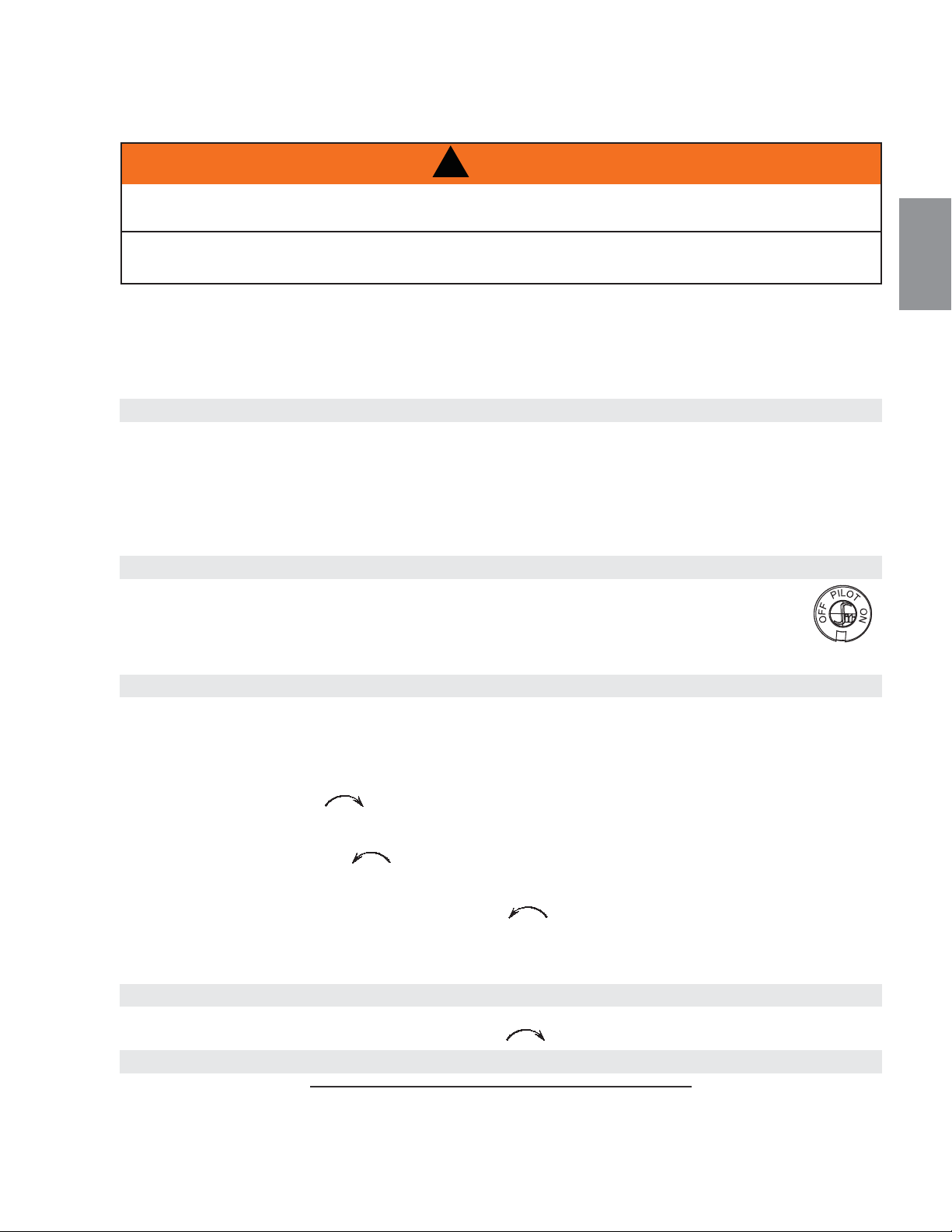
137
W415-1401 / C / 03.19.15
FR
Ensure that a continuous gas flow is at the burner before installing the door. When lit for the first time, the appliance will
emit an odor for a few hours. This is a normal temporary condition caused by the "burn-in" of paints and lubricants used in
the manufacturing process and will not occur again.
A
fter extended periods of non-operation such as following a vacation or a warm weather season, the appliance may emit a
slight odor for a few hours. This is caused by dust particles in the heat exchanger burning off. In both cases, open a
window to sufficiently ventilate the room.
FOR YOUR SAFETY READ BEFORE LIGHTING:
A. This appliance is equipped with a pilot which must be lit by hand while following these instructions exactly.
B. Before operating smell all around the appliance area for gas and next to the floor because some gas is heavier than
air and will settle on the floor.
C. Use only your hand to turn the gas control knob. Never use tools. If the knob will not turn by hand, do not try to
repair it. Call a qualified service technician. Force or attempted repair may result in a fire or explosion.
D. Do not use this appliance if any part has been under water. Immediately call a qualified service technician to inspect
the appliance and replace any part of the control system and any gas control which has been under water.
Turn off all gas to the appliance.
Open windows.
Do not try to light any appliance.
Do not touch any electric switch; do not use any
phone in your building.
GAS KNOB
WARNING: The gas valve has an interlock device which will not allow the pilot burner to be lit until the thermo-
couple has cooled. Allow approximately 60 seconds for the thermocouple to cool.
When lighting and re-lighting, the gas knob cannot be turned from pilot to off unless the knob is depressed slightly.
1. Stop! Read the above safety information on this label.
2. Turn off all electric power to the appliance.
3. Turn the gas knob clockwise to off.
4. Wait five (5) minutes to clear out any gas. If you smell gas including near the floor. Stop! Follow "B" in the
above safety information on this label. If you don't smell gas go the next step.
5. Turn gas knob counter-clockwise to pilot.
6. Depress slightly and hold gas knob while lighting the pilot with the push button igniter. Keep knob depressed for one
minute, then release. If pilot does not continue to burn, repeat steps 3 through 5.
7. With pilot lit, depress and turn gas knob counter-clockwise to on.
8. If equipped with remote on-off switch / thermostat, main burner may not come on when you turn valve to on. Remote
switch must be in the on position to ignite burner.
9. Turn on all electric power to the appliance.
1. Turn off all electric power to the appliance if service is to be performed.
2. Push in gas control knob slightly and turn clockwise to off. Do not force.
Immediately call your gas supplier from a
neighbor's phone. Follow the gas
supplier's instructions.
If you cannot reach your gas supplier,
call the fire department.
WHAT TO DO IF YOU SMELL GAS:
LIGHTING INSTRUCTIONS:
TO TURN OFF GAS
TURN THE CONTROL VALVE TO THE OFF POSITION WHEN HEATER IS NOT IN USE.
47.2
IF YOU DO NOT FOLLOW THESE INSTRUCTIONS EXACTLY, A FIRE OR EXPLOSION MAY RESULT
CAUSING PROPERTY DAMAGE, PERSONAL INJURY OR LOSS OF LIFE.
ALWAYS LIGHT THE PILOT WHETHER FOR THE FIRST TIME OR IF THE GAS SUPPLY HAS RUN OUT WITH
THE GLASS DOOR OPENED OR REMOVED.
!
WARNING
8.0 FONCTIONNEMENT
8.1 B36NTR/GX36NTR & B36PTR/GX36PTR (MILLIVOLT)
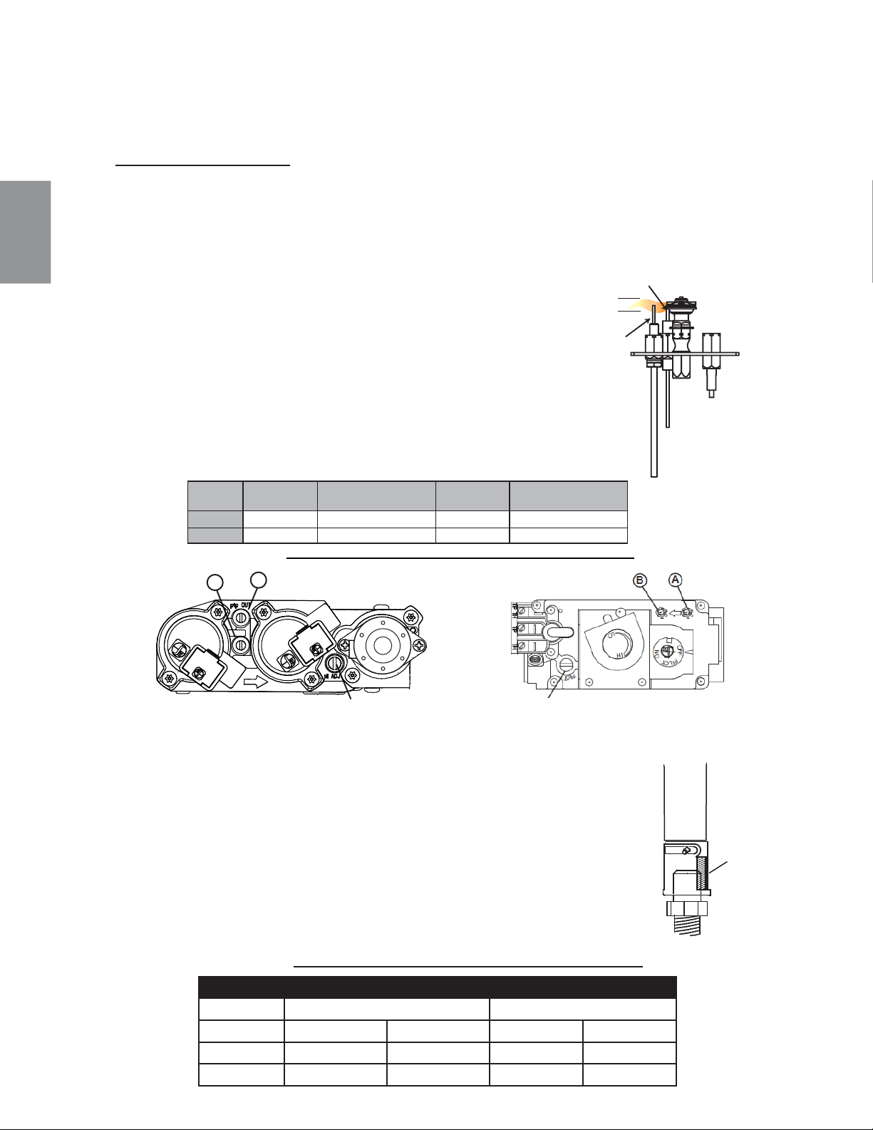
TABLEAU DE RÉGLAGE DU VENTURI
B36 GX36
COMBUSTIBLE
DESSUS ARRIÈRE DESSUS ARRIÈRE
GN 1/16" (1.5mm) 1/16" (1.5mm) 1/4" (6.3mm) 1/4" (6.3mm)
PL 3/8" (9.5mm) 3/8" (9.5mm) 3/8" (9.5mm) FULL OPEN
138
W415-1401 / C / 03.19.15
FR
L’ouverture du volet d’air a été préréglée en usine selon le tableau
ci-dessous :
Indépendamment de l’orientation du venturi, plus le volet est fermé,
plus la flamme est jaune et aura tendance à causer des dépôts de
carbone. Plus le volet est ouvert, plus la flamme est bleue et plus elle a
tendance à se détacher des orifices du brûleur. La flamme peut ne pas
être jaune immé-diatement; allouez de 15 à 30 minutes pour que la
couleur finale de la flamme se stabilise.
LE RÉGLAGE DU VOLET D’AIR DOIT ÊTRE EXÉCUTÉ PAR UN
TECHNICIEN OU INSTALLATEUR QUALIFIÉ!
VENTURI
INJECTEUR
49.1
OUVERTURE
DU VOLET
D’AIR
9.0 RÉGLAGES
9.1 RÉGLAGE DE LA VEILLEUSE
9.2 RÉGLAGE DU VENTURI
ÉLÉCTRONIQUE
MILLIVOLT
Ajustez la vis de la veilleuse pour obtenir une fl amme de taille
normale. Tournez vers la droite pour réduire l’apport de gaz.
VÉRIFIER LA PRESSION :
Pour vérifi er la pression d’arrivée, tournez la vis (A) vers la
gauche deux à trois tours, puis emboîtez le tube du manomètre
sur la pointe d’essai. Le manomètre doit indiquer la pression
comme décrit sur le diagramme ci-dessous. Assurez-vous que le
brûleur principal fonctionne à « HI ».
La vérifi cation de la pression de sortie s’effectue comme
ci-dessus en utilisant la vis (B). Le manomètre doit indiquer
la pression comme décrit sur le diagramme ci-dessous.
Assurez-vous que le brûleur principal fonctionne à « HI ».
APRÈS AVOIR PRIS LA LECTURE DES PRESSIONS,
ASSUREZ-VOUS DE TOURNER FERMEMENT LES VIS
VERS LA DROITE POUR SCELLER. NE SEREZ PAS TROP FORT.
Vérifi ez pour des fuites en apliquant une solution d’eau savonneuse.
Avant d’effectuer le réglage de la veilleuse, assurez-vous que l’assemblage de la
veilleuse n’a pas été peint. S’il y a des traces de peinture ou de surpulvérisation,
enlevez-les de l’assemblage de la veilleuse ou remplacez-le. Une toile d’émeri
ou du papier sablé fi ns peut être utilisé pour enlever la peinture sur la hotte de la
veilleuse, sur l’électrode et sur le capteur de fl amme.
39.1C
A
B
VIS DE LA VEILLEUSE
Pression
Gaz Naturel
(pouces)
Gaz Naturel
(millibars)
Propane
(pouces)
Propane
(millibars)
Arrivée 7” (min.4,5”) 17,4 mb (min.11,2mb) 13” (min.11”) 32,4 mb(min.27,4mb)
Sortie 3,5” 8,7 mb 10” 24,9 mb
3/8” - 1/2”
(9,5mm - 12,7mm)
LA FLAMME DOIT
ENVELOPPER LA PARTIE
SUPÉRIEURE DE LA SONDE
DE FLAMME DE 3/8” (9,5mm)
À 1/2” (12,7mm)
ÉLECTRODE
LA SONDE
DE FLAMME
VEILLEUSE
A
B
ÉLÉCTRONIQUE
ILLUSTRÉ
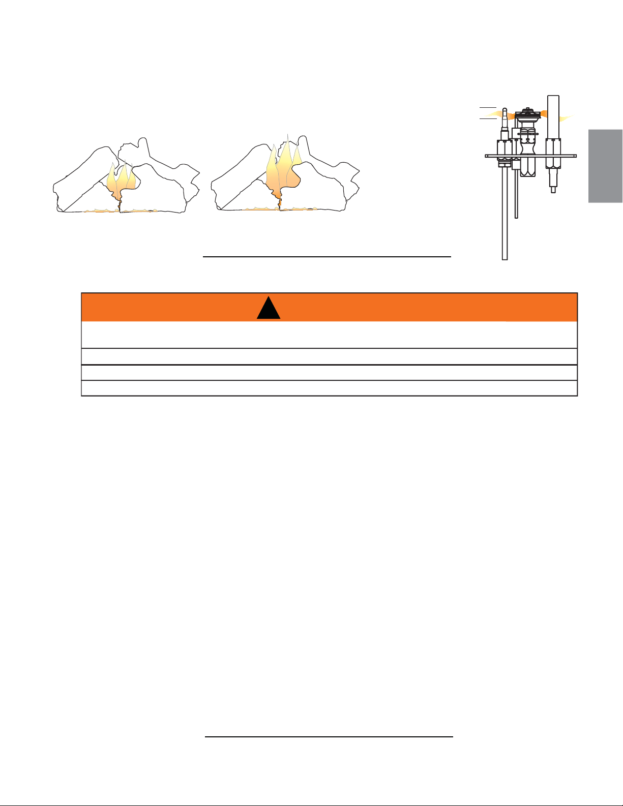
Il est important d’effectuer périodiquement une inspection visuelle de la fl amme de la veilleuse et du brûleur.
Comparez-les à ces illustrations. Si des fl ammes paraissent anormales, contactez un technicien de service.
54.2A
3/8” - 1/2”
(9,5mm - 12,7mm)
LA FLAMME DOIT
ENVELOPPER LA
PARTIE SUPÉRIEURE
DU THERMOCOUPLE
ET DE LA THERMOPILE
DE 3/8" À 1/2"
(9,5mm - 12,7mm)
ATTENTION : Lors de l’entretien des contrôles, assurez-vous d’identifi er chacun des fi ls avant de les
débrancher. Une réinstallation incorrecte des fi ls peut occasionner un mauvais fonctionnement et être
dangereuse. Assurez-vous que l’appareil fonctionne adéquatement une fois l’entretien terminé. Cet appareil
et son système d’évacuation devraient être inspectés avant la première utilisation et au moins une fois l’an
par un technicien de service qualifi é. L’espace entourant l’appareil doit être gardé propre et libre de matériaux
combustibles, d’essence ou autres liquides et vapeurs infl ammables. Les apports d’air comburant et d’air de
convection ne doivent pas être obstrués.
A. Pour nettoyer le brûleur principal et la veilleuse adéquatement, il faut retirer les bûches, les roches ou
la vitre afi n de dégager les deux ensembles.
B. Gardez le compartiment des contrôles, les composants décoratifs, le brûleur, le volet d’air et l’espace
entourant les bûches propres en brossant ou en passant l’aspirateur au moins une fois l’an.
C. Assurez-vous que tous les orifi ces des brûleurs produisent des fl ammes. Nettoyez tous les orifi ces qui
n’ont pas de fl amme ou dont la fl amme ne brûle pas adéquatement.
D. Assurez-vous que la fl amme de la veilleuse est assez puissante pour envelopper la sonde de fl amme
et/ou le thermocouple/thermopile et qu’elle atteigne le brûleur.
E. Remettez en place les bûches, les roches ou la vitre nettoyées, si équipé. Omettre de positionner les
composants décoratifs adéquatement peut causer des dépots de carbone qui peuvent se déposer
dans des endroits de séjour avoisinants.
F. Vérifi ez si le brûleur principal allume sur tous les orifi ces lorsque le bouton de contrôle du gaz est à
« ON ». Un temps d’allumage total de 5 à 10 secondes est satisfaisant. Si l’allumage prend plus de
temps, consultez votre détaillant autorisé.
G. Vérifi ez si les joints d’étanchéité sur les côtés, le haut et le bas de la porte ne sont pas brisés ou
manquants. Remplacez si nécessaire.
H. Si pour une raison quelconque le système d’évents de prise d’air est démonté, réinstallez et rescellez-
le selon les instructions fournies dans l’installation initiale.
I. Il est possible que l’écran de protection (pare-étincelles) nécessite un nettoyage occasionnel en raison
des peluches/poussières provenant des tapis, des animaux, etc. il suffi t de passer l’aspirateur à l’aide
de l’embout avec une brosse.
J. Vérifi ez si le système de décharge effectue effi cacement. Vérifi ez si les joints d’étanchéité ne sont pas
brisés ou manquants. Remplacez si nécessaire.
40.1D
!
AVERTISSEMENT
COUPEZ L’ALIMENTATION EN GAZ ET L’ALIMENTATION ÉLECTRIQUE AVANT DE PROCÉDER À
L’ENTRETIEN DE L’APPAREIL.
L’APPAREIL PEUT ÊTRE CHAUD. ATTENDEZ QU’IL SOIT REFROIDI AVANT D’EN FAIRE L’ENTRETIEN.
N’UTILISEZ PAS DE PRODUITS ABRASIFS.
NE PEINTURE PAS L’ASSEMBLAGE DU VEILLEUSE.
10.0 ENTRETIEN
MILLIVOLT
ILLUSTRÉ
B36
GX36
10.1 CARACTÉRISTIQUES DE LA FLAMME
139
W415-1401 / C / 03.19.15
FR
10.2 ENTRETIEN ANNUEL
LE CAISSON DEVIENT TRÈS CHAUD LORS DU FONCTIONNEMENT. LAISSEZ L’APPAREIL SE
REFROIDIR COMPLÈTEMENT OU PORTEZ DES GANTS ANTICHALEUR AVANT D’EFFECTUER
L’ENTRETIEN.
NE JAMAIS ASPIRER DES BRAISES QUI SONT CHAUDES.
NE PEINTUREZ PAS L’ASSEMBLAGE DE LA VEILLEUSE.
!
AVERTISSEMENT
37.1C
• Cet appareil nécessite un entretien qui devra être effectué sur une base annuelle.
• L’entretien devrait inclure un nettoyage, le remplacement des piles, une inspection du système d’évent,
du brûleur, des éléments décoratifs internes et de la chambre de combustion. Consultez la section pour
l’enlèvement de la porte et retirez la porte comme indiqué.
• Enlevez soigneusement les éléments décoratifs internes s’il y a lieu (bûches, braises de verre, panneaux
de brique, etc.)
• À l’aide d’un aspirateur muni d’une brosse souple, aspirez les saletés, les débris et les dépôts de carbone
sur les bûches, la chambre de combustion et le brûleur. Pour les braises de verre, suivez les instructions
de prénettoyage.
• Enlevez aussi tout dépôt se trouvant sur l’assemblage de la veilleuse et aussi, s’il y a lieu, sur la
thermopile, le thermocouple, le capteur de fl amme et l’allumeur.
NOTE: Vous devrez possiblement
nettoyer le capteur de fl amme à l’aide d’une morceau de de laine d’acier ou Scotch-Brite™ afi n de
retirer toute trace d’oxydation. Nettoyez l’assemblage du pilote à
l’aide d’un aspirateur muni d’une
brosse souple.
Il est important de ne pas peinturer l’assemblage de la veilleuse.
• Inspectez tous les joints d’étanchéité accessibles et remplacez-les au besoin.
• Accédez à la souffl erie, s’il y a lieu, puis nettoyez à l’aide d’une brosse souple et d’un aspirateur.
• Réinstallez tous les composants dans l’ordre inverse.
• Inspectez le système de surpression. L’appareil dissipe la pression par la porte vitrée ou par les clapets
sur le dessus du caisson. Assurez-vous qu’ils ouvrent sans restriction et qu’ils ferment de façon étanche.
• Vérifi ez si la soupape de gaz de la veilleuse et les boutons Hi / Lo bougent librement (s’il y a lieu) -
remplacez si vous constatez de la rigidité dans le mouvement.
• Vérifi ez tous les branchements du gaz pour des fuites de gaz, en amont et en aval de la soupape de gaz
incluant les connexions du tube de la veilleuse.
140
W415-1401 / C / 03.19.15
FR
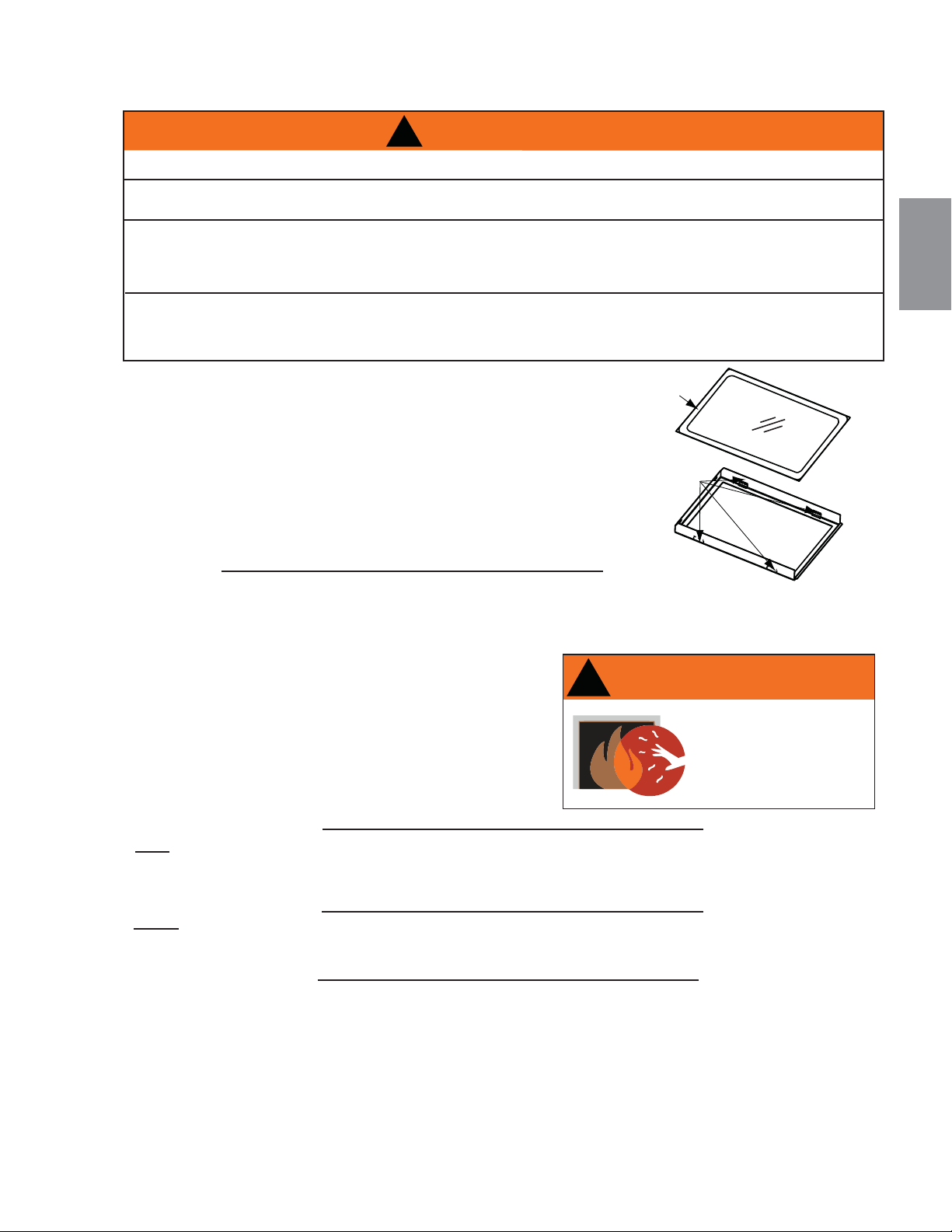
141
W415-1401 / C / 03.19.15
FR
A. Placez le cadre de la porte avec la devanture vers le bas en
prenant soin de ne pas égratigner la peinture.
B. Centrez la vitre avec joint d’étanchéité dans le cadre avec le
côté épais du joint d’étanchéité orienté vers le haut.
C. Pliez les pattes de retenue situées sur le cadre par-dessus le
joint d’étanchéité pour retenir la vitre en place. Faites attention
à ne pas casser la vitre.
VITRE
JOINT
D’ÉTANCHÉITÉ
CADRE DE
PORTE
PATTE DE
RETENUE
!
AVERTISSEMENT
N’UTILISEZ PAS DE MATÉRIAUX DE SUBSTITUTION.
LA VITRE PEUT ÊTRE CHAUDE, NE TOUCHEZ PAS LA VITRE JUSQU’À CE QU’ELLE AIT REFROIDI.
USEZ DE PRUDENCE LORSQUE VOUS ENLEVEZ ET JETEZ DES DÉBRIS DE VERRE
OU DES COMPOSANTS ENDOMMAGÉS. ASSUREZ-VOUS D’ASPIRER TOUS LES DÉBRIS DE
VERRE À L’INTÉRIEUR DE L’APPAREIL AVANT DE LE FAIRE FONCTIONNER.
NE FRAPPEZ PAS, NE CLAQUEZ PAS ET N’ÉGRATIGNEZ PAS LA PORTE VITRÉE. NE FAITES PAS
FONCTIONNER L’APPAREIL LORSQUE LA PORTE VITRÉE EST ENLEVÉE, FISSURÉE, BRISÉE OU
ÉGRATIGNÉE.
56.1A
10.3 REMPLACEMENT DE LA VITRE DE PORTE
5.1
NE PAS NETTOYER LA VITRE LORSQU’ELLE EST
CHAUDE! N’EMPLOYEZ PAS DE DÉTERGENTS
ABRASIFS POUR NETTOYER LA VITRE.
Polissez légèrement à l’aide d’un linge propre et sec.
Nettoyez les deux côtés de la vitre avec un nettoyeur
recommandé après les dix premières heures de
fonctionnement. Par la suite, nettoyez aussi souvent
qu’il le faudra, sinon la vitre risque de rester marquée en
LA VITRE CHAUDE CAUSERA
DES BRÛLURES.
NE PAS TOUCHER LA VITRE
AVANT QU’ELLE AIT REFROIDI.
NE JAMAIS LAISSER LES
ENFANTS TOUCHER LA VITRE.
!
AVERTISSEMENT
10.4 SOINS DE LA VITRE
5.5
L’appareil est muni d’une 4mm vitre en verre trempé. Remplacez uniquement avec une vitre certifi ée pour le
foyer disponible chez votre détaillant Napoléon. N’UTILISEZ PAS DE MATÉRIAUX SUBSTITUTS.
5.5.1
L’appareil est muni d’une 5mm en verre céramique Remplacez uniquement avec une vitre certifi ée pour le
foyer disponible chez votre détaillant Napoléon. N’UTILISEZ PAS DE MATÉRIAUX SUBSTITUTS.
B36:
GX36:

Contactez votre détaillant pour les questions concernant les prix et la disponibilité des pièces de rechange.
Normalement, toutes les pièces peuvent être commandées chez votre détaillant autorisé.
POUR UN REMPLACEMENT DE PIÈCE SOUS GARANTIE, UNE PHOTOCOPIE DE LA FACTURE
ORIGINALE SERA REQUISE AFIN DE POUVOIR HONORER LA DEMANDE.
Lorsque vous commandez des pièces, donnez toujours l’information suivante :
● Modèle et numéro de série de l’appareil
● Date d’installation de l’appareil
● Numéro de la pièce
● Description de la pièce
● Fini
* IDENTIFIE LES ARTICLES QUI NE SONT PAS ILLUSTRÉS. POUR PLUS D’INFORMATION, CONTACTEZ
V
OTRE DÉTAILLANT AUTORISÉ.
41.2
OMETTRE DE POSITIONNER LES PIÈCES CONFORMÉMENT À CE MANUEL OU D’UTILISER UNIQUEMENT DES
PIÈCES SPÉCIFIQUEMENT APPROUVÉES POUR CET APPAREIL PEUT CAUSER DES DOMMAGES MATÉRIELS
OU DES BLESSURES CORPORELLES.
** CECI EST UN THERMOCOUPLE À ACTION RAPIDE QUI CONSTITUE UN COMPOSANT ESSENTIEL DE
SÉCURITÉ. REMPLACEZ UNIQUEMENT PAR UN THERMOCOUPLE À ACTION RAPIDE DE WOLF STEEL LTÉE.
!
AVERTISSEMENT
142
W415-1401 / C / 03.19.15
FR
11.0 RECHANGES
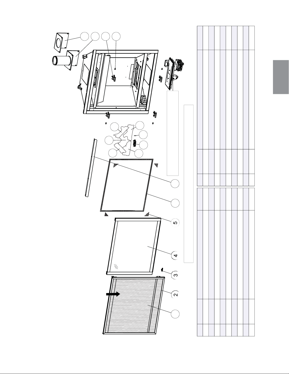
143
W415-1401 / C / 03.19.15
FR
L’ASSEMBLAGE DE
L’ÉCRAN DE PROTECTION
GL-696
RÉF. PART NO. DESCRIPTION
3
4
5
6
7
8
9
RÉF. PART NO. DESCRIPTION
W565-0144 ÉCRAN DE PROTECTION
W010-3402
L’ASSEMBLAGE DE LA PORTE
W335-0063 HOTTE
BÛCHE CROISÉ GAUCHE (GL-696)
BÛCHE DE L’ARRIÈRE (GL-696)
W135-0546
W135-0588
2
1
EN STOCK
EN STOCK
OUI
OUI
OUI
OUI
GOUPILLE DES BÛCHES (GL-696)
W485-0042
W385-0334
LOGO NAPOLÉON
10
18
14
15
16
17
13
OUI
OUI
W570-0135
VIS À ÉPAULEMENT (X4)
OUI
W010-3070
LOQUET DE PORTE (X4)
W290-0259 L'ASSEMBLAGE DE TUYAU DU JOINT D’ÉTANCHÉITÉ
W010-3279 L’ASSEMBLAGE DE CONDUIT D’ÉVACUATION 4”
OUI
LES BRAISES LUISANTES (GL-696)
W361-0016
W562-0009
JOINT D’ÉTANCHÉITÉ DE LA PORTE
W667-0018 JOINT D’ÉTANCHÉITÉ RUBAN (X4)
OUI
OUI
OUI
BÛCHE DU CÔTÉ DRIOTE (GL-696)
W135-0545
OUI
BÛCHE DU CÔTÉ GAUCHE (GL-696)
W135-0544
12
W010-3072
L’ASSEMBLAGE DE L’ÉCRAN DE PROTECTION
11
BÛCHE CROISÉ DROITE (GL-696)W135-0589
OUI
OUI
201 202 203 204 205 206
207
8
9
1010
11
13
14
12
15
16
17
18
CES ARTICLES PEUT DIFFÉRER DE CELLE ILLUSTRÉ
POUR LES PIÉCES DE REMPLACEMENT
VOIR "L’ASSEMBLAGE DE LA SOUPAPE"
12.0 VUE D'ENSEMBLE DE B36
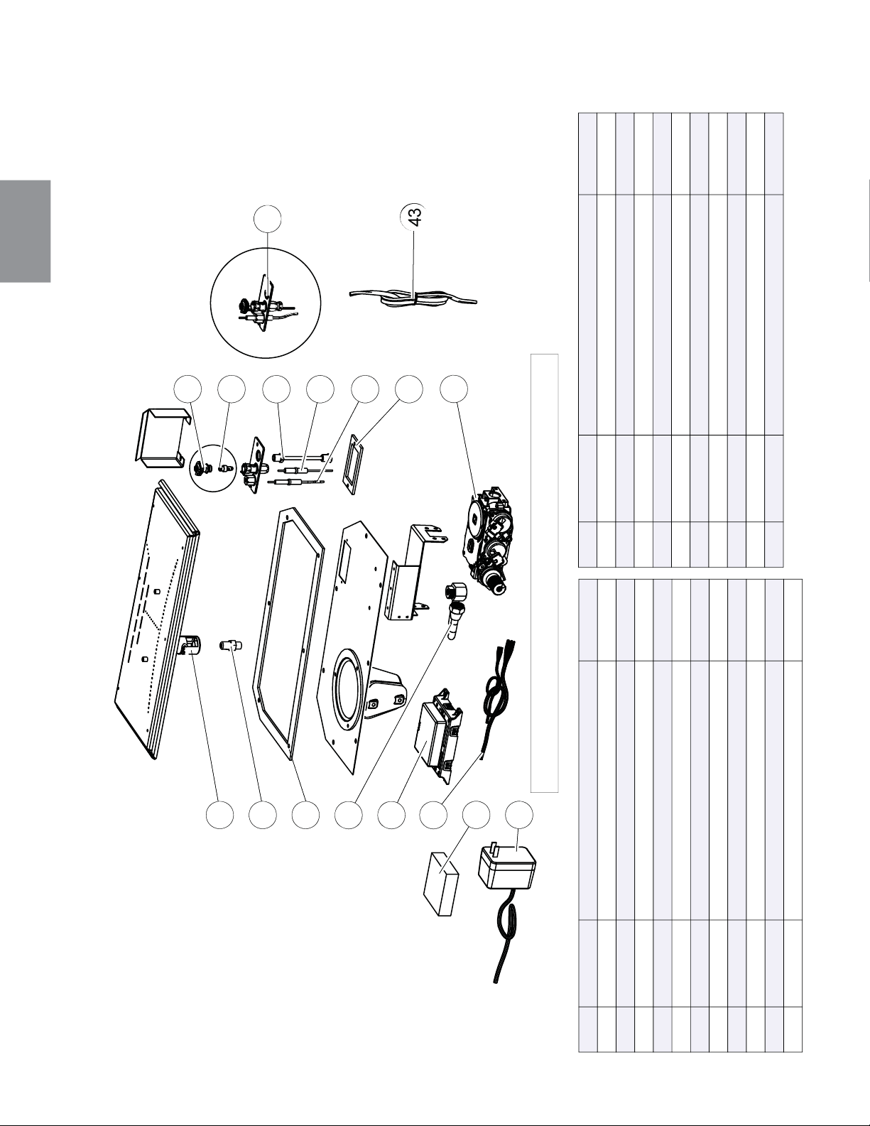
144
W415-1401 / C / 03.19.15
FR
13.0 L'ASSEMBLAGE DE LA SOUPAPE DE ELECTRONIQUE B36
RÉF. PART NO. DESCRIPTION EN STOCK
W432-0046
CONNECTEUR FLEXIBLE
OUI
W190-0022
MODULE DE CONTRÔLE
OUI
W750-0309
HARNAIS DE FILS
OUI
W350-0702 SAUVEGARDE DE PILE OUI
W707-0010 TRANSFORMATEUR OUI
W725-0062 886 SOUPAPE PROFLAMME (GN) OUI
W725-0063 886 SOUPAPE PROFLAMME (PL) OUI
W010-2763
ENSEMBLE DE VEILLEUSE (GN)
W010-0799
ENSEMBLE DE VEILLEUSE (PL)
W010-1986 ENSEMBLE DE FILS OUI
RÉF. PART NO. EN STOCK
19 W100-0169 OUI
20 W456-0047 OUI
20 W456-0056 OUI
21 W290-0248 OUI
25 W335-0039 OUI
27 W455-0070 OUI
27 W455-0068 OUI
29 W720-0062 OUI
30 W240-0006 OUI
32 W290-0029
35 W245-0025 OUI
43
36
31
30
28
26
37
23
21
20
42
40
38
33
39
44
41
42
35
30
29
27
25
36
21
20
19
41
39
37
32
38
43
40
CES ARTICLES PEUT DIFFÉRER DE CELLE ILLUSTRÉ
DESCRIPTION
ASSEMBLAGE DE BRÛLEUR
INJECTEUR DE VEILLEUSE #49 (GN)
INJECTEUR DE VEILLEUSE #57 (PL)
JOINT D’ÉTANCHÉITÉ DE SOUPAPE
HOTTE DU VEILLEUSE
INJECTEUR DE VEILLEUSE #62 (GN)
INJECTEUR DE VEILLEUSE #35 (PL)
TUBE DE VEILLEUSE, RACCORD
ALLUMEUR (AVEC FILS)
JOINT D’ÉTANCHÉITÉ DU VEILLEUSE
THERMOSENSOR
36
37
38
39
40
41
41
42
42
43
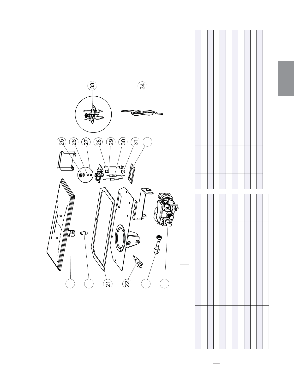
145
W415-1401 / C / 03.19.15
FR
14.0 L'ASSEMBLAGE DE LA SOUPAPE DE MILLIVOLT B36
RÉF. PART NO. DESCRIPTION EN STOCK
19 W100-0190
20 W456-0047
20 W456-0056
21
22
W290-0248
23 W432-0078
24 W725-0025
24 W725-0043
25 W335-0039
26 W455-0070
26 W455-0068
RÉF. PART NO. EN STOCK
27 W010-0801 OUI
27 W010-0800
28 W680-0004
29 W720-0062
30 W240-0006
31 W680-0005
32 W290-0029
33 W010-0798
33 W010-0799
34 W750-0112
34
28
32
31
30
29
27
26
24
23
21
20
22
25
33
35
33
27
31
30
29
28
26
25
23
22
20
19
21
24
32
34
W357-0001
CES ARTICLES PEUT DIFFÉRER DE CELLE ILLUSTRÉ
OUI
OUI
OUI
OUI
OUI
OUI
OUI
OUI
OUI
OUI
OUI
OUI
OUI
OUI
OUI
OUI
ASSEMBLAGE DE BRÛLEUR
INJECTEUR DE VEILLEUSE #47 (GN)
INJECTEUR DE VEILLEUSE #56 (PL)
JOINT D’ÉTANCHÉITÉ DE SOUPAPE
BOUTON D’ALLUMEUR
CONNECTEUR FLEXIBLE
SOUPAPE (GN)
SOUPAPE (PL)
HOTTE DU VEILLEUSE
INJECTEUR DE VEILLEUSE #62 (GN)
INJECTEUR DE VEILLEUSE #35 (PL)
DESCRIPTION
VEILLEUSE (GN)
VEILLEUSE (PL)
THERMOPILE
TUBE DE VEILLEUSE, RACCORD
ALLUMEUR (AVEC FILS)
THERMOCOUPLE
JOINT D’ÉTANCHÉITÉ DU VEILLEUSE
ENSEMBLE DE VEILLEUSE (GN)
ENSEMBLE DE VEILLEUSE (PL)
ENSEMBLE DE FILS
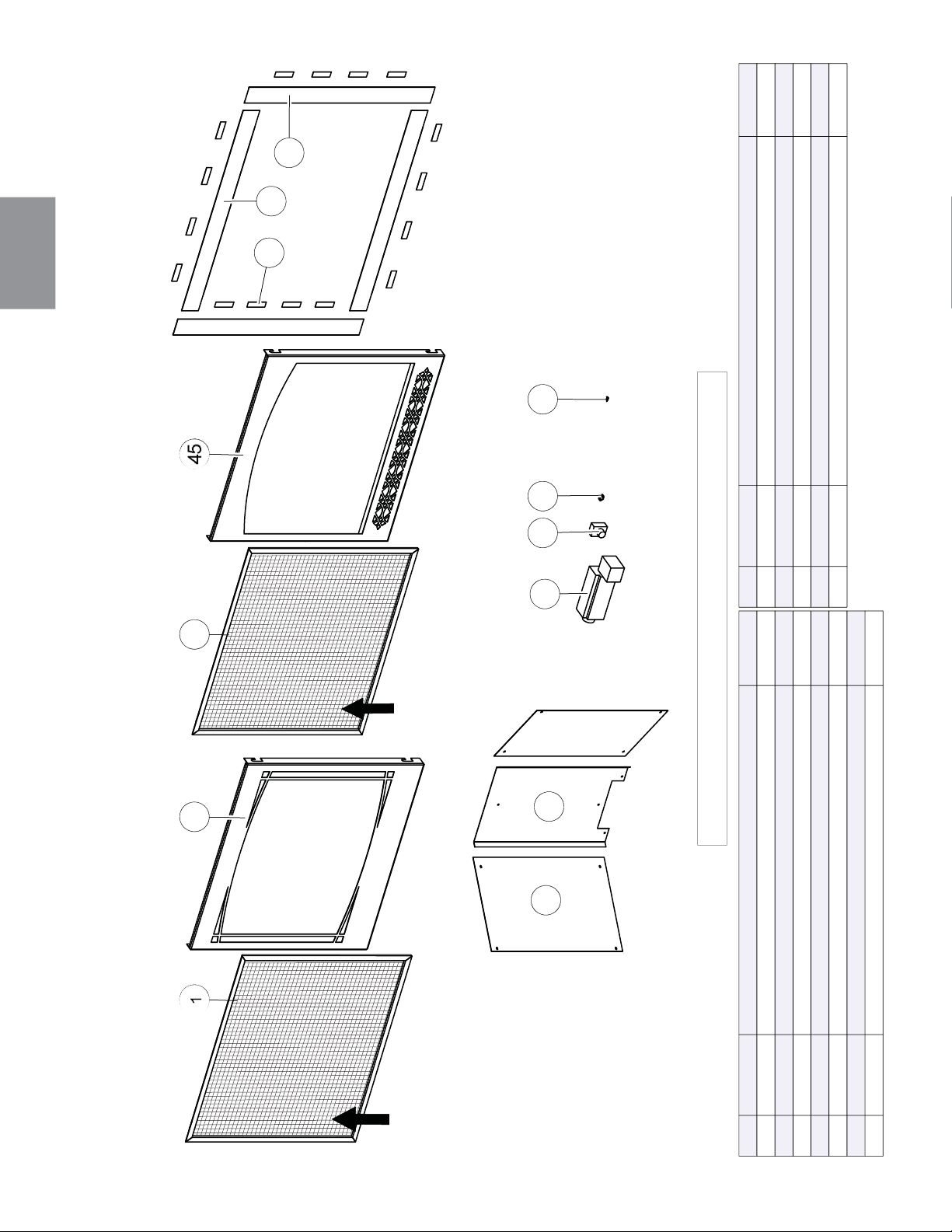
146
W415-1401 / C / 03.19.15
FR
15.0 ACCESSORIES B36
RÉF. PART NO. DESCRIPTION EN STOCK
W565-0144 ÉCRAN DE PROTECTION (Z35F & H35F)
OUI
W010-3281 ZEN FAÇADE DÉCORATIVE (Z35F)
W010-3282 HERRITAGE FAÇADE DÉCORATIVE (H35F)
W430-0003 AIMANTS (X16) (TK35) OUI
W715-0953 GARNITURE SUPÉIEURE / INFÉRIEURE (X2) (TK35)
W715-0952 GARNITURE DU CÔTÉ (X2) (TK35)
W475-1012 PANNEAU DE PORCELAINE DU CÔTÉ (X2) (PRPB36)
RÉF. PART NO. DESCRIPTION EN STOCK
W475-1012 PANNEAU DE PORCELAINE DE L’ARRIÉRE (PRPB36)
W062-0051 SOUFFLERIE (AUB) OUI
KB-35 INTERRUPTEUR À VITESSE VARIABLE OUI
W690-0002 THERMODISQUE OUI
W715-0191 INTERRUPTEUR ACS (ACS) OUI
54
1
47
145
53
52
46
48
49
55
50
51
53
1
46
144
52
51
45
47
48
54
49
50
TK35
PRPB36 AUB
H35FZ35F
CES ARTICLES PEUT DIFFÉRER DE CELLE ILLUSTRÉ
L’ÉCRAN DE
PROTECTION
L’ÉCRAN DE
PROTECTION
1
44
45
46
47
48
49
50
51
52
53
54
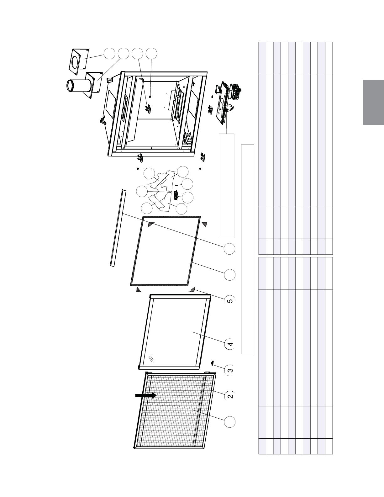
147
W415-1401 / C / 03.19.15
FR
16.0 VUE D'ENSEMBLE DE GX36
L'ASSEMBLAGE DE
L’ÉCRAN DE PROTECTION
RÉF. PART NO. DESCRIPTION
3
4
5
6
7
8
9
RÉF. PART NO. DESCRIPTION
W565-0144 ÉCRAN DE PROTECTION
W010-3402 ASSEMBLAGE DE LA PORTE
W335-0063 HOTTE
BÛCHE CROISÉ GAUCHE (GL-696)
BÛCHE DE L’ARRIÉRE (GL-696)
W135-0546
W135-0588
2
1
EN STOCK EN STOCK
OUI
OUI
OUI
OUI
GOUPILLE DES BÛCHES (GL-696)
W485-0042
W385-0334 LOGO NAPOLÉON
OUI
OUI
W570-0135 VIS À ÉPAULEMENT (X4)
OUI
W010-3070 LOQUET DE PORTE (X4)
W290-0259 L'ASSEMBLAGE DE TUYAU DU JOINT D’ÉTANCHÉITÉ
W010-3279 L’ASSEMBLAGE DE CONDUIT D’ÉVACUATION 4”
OUI
LES BRAISES LUISANTES (GL-696)
W361-0016
W562-0009 JOINT D’ÉTANCHÉITÉ DE LA PORTE
W667-0018 JOINT D’ÉTANCHÉITÉ RUBAN (X4)
OUI
OUI
OUIBÛCHE DU CÔTÉ DROITE (GL-696)W135-0545
OUI
BÛCHE DU CÔTÉ GAUCHE (GL-696)
W135-0544
W010-3072 L’ASSEMBLAGE DE LÉCRAN DE PROTECTION
BÛCHE CROISÉ DROITE (GL-696)W135-0589 OUI
GL-696
201 202 203 204 205 206
207
8
9
1010
11
13
14
12
15
16
17
18
CES ARTICLES PEUT DIFFÉRER DE CELLE ILLUSTRÉ
POUR LES PIÉCES DE REMPLACEMENT
VOIR "L’ASSEMBLAGE DE LA SOUPAPE"
10
18
14
15
16
17
13
12
11
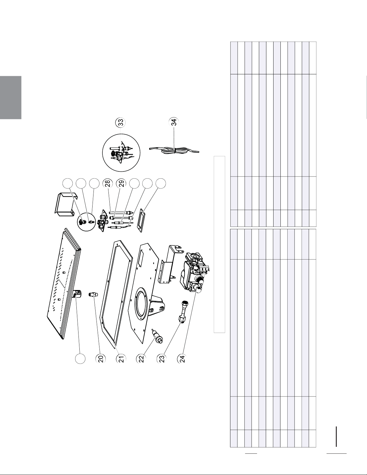
148
W415-1401 / C / 03.19.15
FR
17.0 L'ASSEMBLAGE DE LA SOUPAPE DE MILLIVOLT GX36
33
27
31
30
29
28
26
23
25
21
19
20
24
32
22
34
33
27
31
30
29
28
26
23
25
21
19
20
24
32
22
34
CES ARTICLES PEUT DIFFÉRER DE CELLE ILLUSTRÉ
RÉF.
PART NO. DESCRIPTION
EN STOCK
19 W100-0191 ASSEMBLAGE DE BRÛLEUR OUI
RÉF.
PART NO. DESCRIPTION
EN STOCK
27
27
28
29
30
31
32
33
33
34
W010-0801
W010-0800
W680-0004
W720-0062
W240-0006
W680-0005
W290-0029
W010-0798
W010-0799
W750-0112
THERMOPILE
VEILLEUSE (GN)
VEILLEUSE (PL)
TUBE DE VEILLEUSE, RACCORD
ALLUMEUR (AVEC FILS)
THERMOCOUPLE
JOINT D’ÉTANCHÉITÉ DU VEILLEUSE
ENSEMBLE DE VEILLEUSE (GN)
ENSEMBLE DE VEILLEUSE (PL)
ENSEMBLE DE FILS
OUI
OUI
OUI
OUI
OUI
OUI
26 W455-0068 INJECTEUR DE VEILLEUSE #35 (PL) OUI
20
20
21
22
23
24
24
25
26
W456-0043
W456-0053
W290-0248
W432-0078
W725-0025
W725-0043
W335-0039
W455-0070
W357-0001
INJECTEUR DE VEILLEUSE (ARRIÈRE) #43 (GN)
INJECTEUR DE VEILLEUSE #53 (PL)
JOINT D’ÉTANCHÉITÉ DE SOUPAPE
CONNECTEUR FLEXIBLE
SOUPAPE (GN)
SOUPAPE (PL)
HOTTE DU VEILLEUSE
INJECTEUR DE VEILLEUSE #62 (GN)
BOUTON D’ALLUMEUR
OUI
OUI
OUI
OUI
OUI
OUI
OUI
OUI
OUI
20 W456-0042 INJECTEUR DE VEILLEUSE (SUPÉRIEURE) #42 (GN) OUI
NOTE: Une #42 injecteur a été fourni avec votre appareil. Dans les installations avec un verticale augmenter supérieur à 8 "(203mm)
dans la confi guration d'évacuation, le #42 injecteur doit être utilisé pour augmenter la taille de la fl amme.
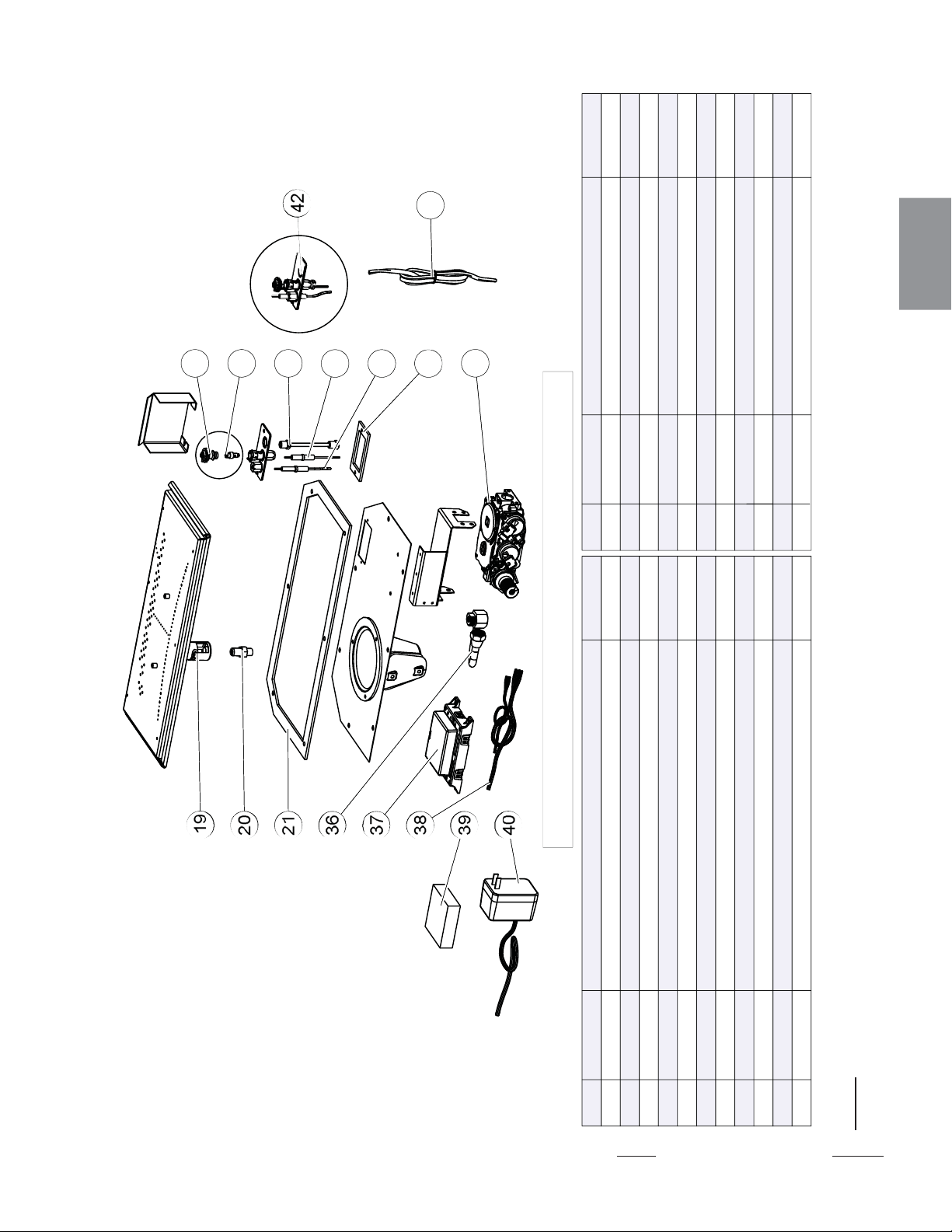
149
W415-1401 / C / 03.19.15
FR
18.0 L'ASSEMBLAGE DE LA SOUPAPE DE ELECTRONIQUE GX36
42
35
30
29
26
25
36
21
19
20
41
39
37
38
32
43
40
42
35
30
29
26
25
36
21
19
20
41
39
37
38
32
43
40
CES ARTICLES PEUT DIFFÉRER DE CELLE ILLUSTRÉ
RÉF. PART NO. DESCRIPTION EN STOCK
W100-0191 ASSEMBLAGE DE BRÛLEUR OUI
RÉF. PART NO. EN STOCK
19
INJECTEUR DE VEILLEUSE (ARRIÈRE) #43 (GN)
INJECTEUR DE VEILLEUSE (SUPÉRIEURE) #42 (GN)
OUI
OUI
OUI
OUI
OUI
OUI
OUI
OUI
DESCRIPTION
CONNECTEUR FLEXIBLE
MODULE DE CONTRÔLE
HARNAIS DE FILS
SAUVEGARDE DE PILE
TRANSFORMATEUR
886 SOUPAPE PROFLAMME (GN)
886 SOUPAPE PROFLAMME (PL)
ENSEMBLE DE VEILLEUSE (GN)
ENSEMBLE DE VEILLEUSE (PL)
ENSEMBLE DE FILS
W432-0046
W190-0022
W750-0309
W350-0702
W707-0010
W725-0062
W725-0063
W010-2763
W010-0799
W010-1986
36
37
38
39
40
41
41
42
42
43
W245-0025 THERMOSENSOR OUI
35
W456-0043
W456-0053
W290-0248
W335-0039
W455-0070
W455-0068
W720-0062
W240-0006
W290-0029
20
20
21
25
26
26
29
30
32
INJECTEUR DE VEILLEUSE #53 (PL)
JOINT D’ÉTANCHÉITÉ DE SOUPAPE
HOTTE DU VEILLEUSE
INJECTEUR DE VEILLEUSE #62 (GN)
INJECTEUR DE VEILLEUSE #35 (PL)
TUBE DE VEILLEUSE, RACCORD
ALLUMEUR (AVEC FILS)
JOINT D’ÉTANCHÉITÉ DU VEILLEUSE
OUI
OUI
OUI
OUI
OUI
OUI
OUI
OUI
W456-0042
20
NOTE: Une #42 injecteur a été fourni avec votre appareil. Dans les installations avec un verticale augmenter supérieur à 8
"(203mm) dans la confi guration d'évacuation, le #42 injecteur doit être utilisé pour augmenter la taille de la fl amme.
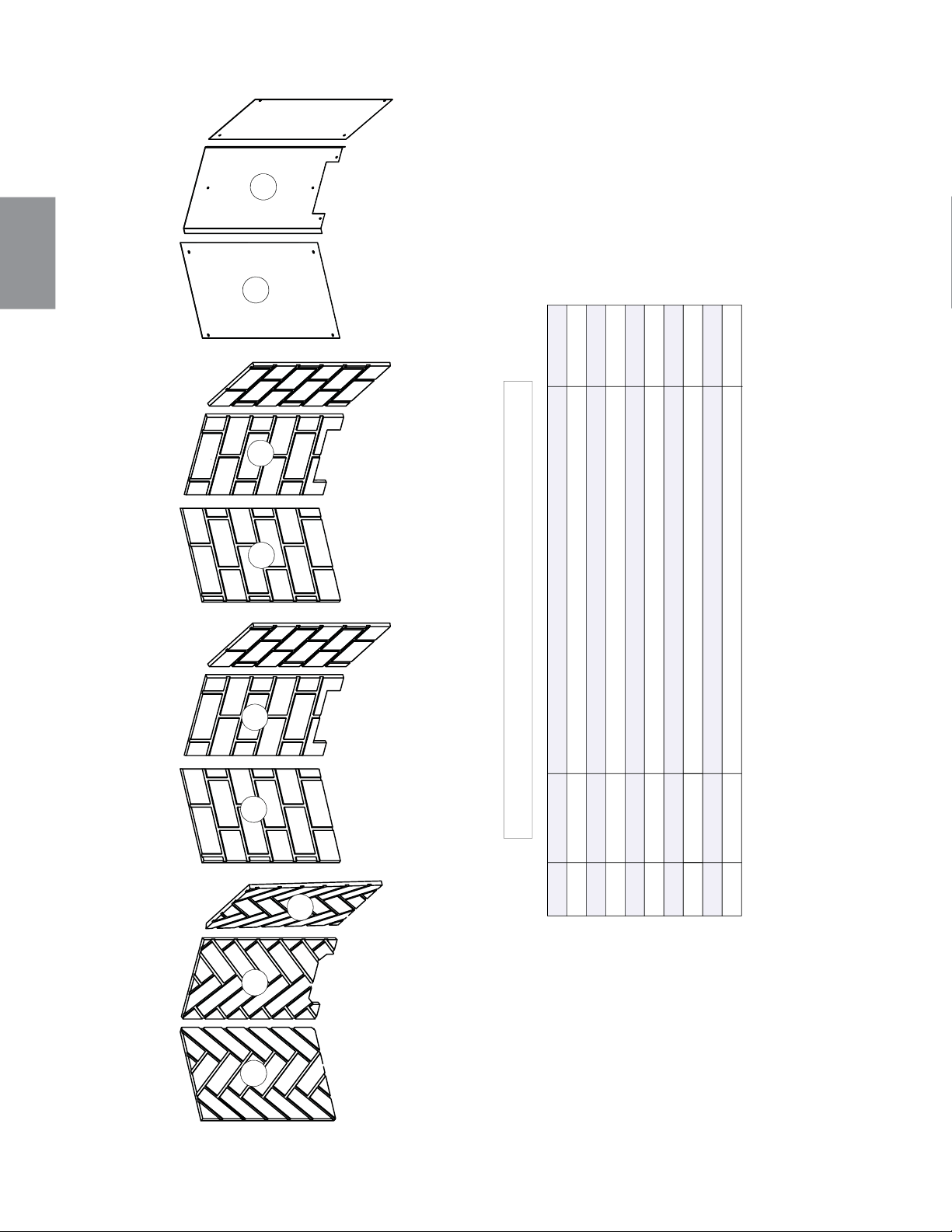
150
W415-1401 / C / 03.19.15
FR
19.0 ACCESSORIES GX36
GD861KT
PRPB36
GD863KTGD862KT
44
45
46
47
48
49
50
51
52
RÉF. PART NO. DESCRIPTION EN STOCK
PANNEAU DE HERRINGBONE DU CÔTÉ GAUCHE (GD861KT)
PANNEAU DE HERRINGBONE DU L’ARRIÉRE (GD861KT)
W475-0994
W475-0993
PANNEAU DE BRIQUE SANDSTONE DU CÔTÉ (X2) (GD862KT)
PANNEAU DE BRIQUE SANDSTONE DU L’ARRIÉRE (GD862KT)
W475-0992
W475-0991
PANNEAU DE HERRINGBONE DU CÔTÉ DROITE (GD861KT)W475-0995
PANNEAU DE PORCELAINE DU CÔTÉ (X2) (PRPB36)
PANNEAU DE PORCELAINE DE L’ARRIÉRE(PRPB36)
W475-0989
W475-0990
PANNEAU DE BRIQUE NEWPORT DU CÔTÉ (X2) (GD863KT)
PANNEAU DE BRIQUE NEWPORT DU L’ARRIÉRE(GD863KT)
W475-0997
W475-0996
CES ARTICLES PEUT DIFFÉRER DE CELLE ILLUSTRÉ
45
46
47
48
44
52
49
50
51
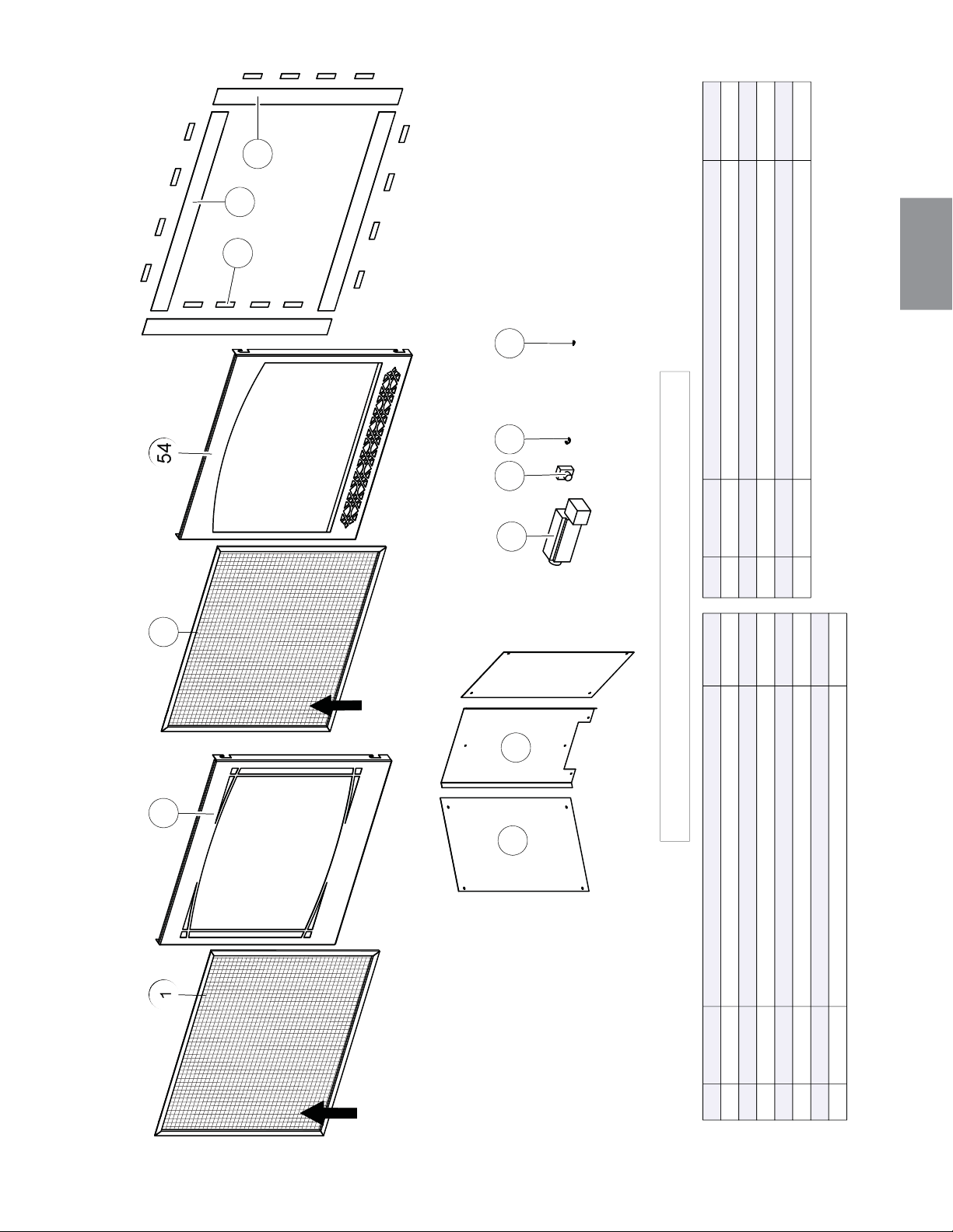
151
W415-1401 / C / 03.19.15
FR
54
1
47
145
53
52
46
48
49
55
50
51
62
1
55
153
61
60
54
56
57
63
58
59
TK35
PRPB36 AUB
H35FZ35F
RÉF. PART NO. DESCRIPTION EN STOCK
W565-0144 L’ÉCRAN DE PROTECTION (Z35F & H35F)
OUI
W010-3281 L’ASSEMBLAGE AVANT ZEN (Z35F)
W010-3282 L’ASSEMBLAGE AVANT HERITAGE (H35F)
W430-0003 AIMANTS (X16) (TK35) OUI
W715-0953 GARNITURE SUPÉRIEURE / INFÉRIEURE (X2) (TK35)
W715-0952 GARNITURE DU CÔTÉ (X2) (TK35)
W475-1012 PANNEAU DE PORCELAINE DU CÔTÉ (X2) (PRPB36)
RÉF. PART NO. DESCRIPTION EN STOCK
W475-1012 PANNEAU DE PORCELAINE DE L’ARRIÈRE (PRPB36)
W062-0051 SOUFFLERIE (AUB) OUI
KB-35 INTERRUPTEUR À VITESSE VARIABLE OUI
W690-0002 THERMODISQUE OUI
W715-0191 INTERRUPTEUR ACS (ACS) OUI
L’ÉCRAN DE
PROTECTION
L’ÉCRAN DE
PROTECTION
CES ARTICLES PEUT DIFFÉRER DE CELLE ILLUSTRÉ
1
53
54
55
56
57
58
59
60
61
62
63
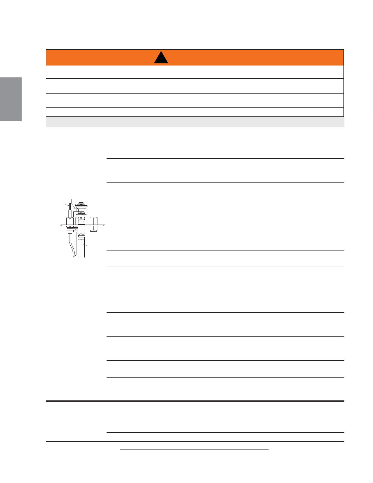
SYMPTÔME PROBLÈME SOLUTIONS
La veilleuse ne
s’allume pas.
Il y a du bruit, mais
aucune étincelle
au brûleur de la
veilleuse.
Filage
.
- Vérifi ez si le fi l « S » pour la sonde et le fi l « I » pour
l’allumeur sont raccordés aux bonnes bornes (non
inversés) sur le module d’allumage et l’assemblage de la
veilleuse.
Connexion desserrée. - Vérifi ez qu’il n’y ait pas de connexions desserrées, de
courts-circuits dans le fi lage ou des contacts avec des
objets métalliques.
Module d’allumage. - Mettez l’interrupteur MARCHE/ARRÊT à « OFF ». Retirez
le fi l d’allumage « I » du module. Mettez l’interrupteur
MARCHE/ARRÊT à « ON ». Tenez un fi l mis à la terre à
environ 3/16”
(4.8mm)
de la borne « I » sur le module.
S’il n’y a pas d’étincelle, la borne « I » du module doit être
remplacée. S’il y a une étincelle, la borne « I » fonctionne
bien. Inspectez l’assemblage de la veilleuse pour un fi l
causant un court-circuit ou un isolateur craqué autour de
l’électrode.
La longueur de l’étincelle
est incorrecte.
- La longueur de l’étincelle de l’allumeur à la veilleuse
devrait être de 0,17” ou 1/8”
(3.2mm)
.
Transformateur. - Vérifi ez si le transformateur est installé et branché dans
le module. Vérifi ez le voltage du transformateur sous
tension aux connexions sur le module avec l’interrupteur
MARCHE/ARRÊT à « ON ». Les lectures acceptables
d’un bon transformateur se situent entre 3,2 et 2,8 volts
C.A.
Système de dépannage
à piles (s’il y a panne de
courant)
- Vérifi ez les piles
Une connexion desserrée
ou causant un court-circuit.
- Retirez et réinstallez le harnais de fi ls qui se branche
dans le module. Retirez et vérifi ez la continuité de chaque
fi l dans le harnais de fi ls.
Filage d’interrupteur
inapproprié.
- Réparez le système avec un simple interrupteur MARCHE/
ARRÊT.
Le module n’est pas mis
à la terre.
- Vérifi ez si les assemblages de la veilleuse et de la
soupape sont bien mis à la terre au niveau du châssis
métallique de l’appareil ou de l’ensemble de bûches.
Étincelle à la
veilleuse, mais
celle-ci ne s’allume
pas.
Alimentation en gaz. - Vérifi ez si la soupape à bille de la conduite d’arrivée du
gaz est « Ouverte ». Vérifi ez si la pression d’arrivée est
dans les limites acceptables. La pression d’arrivée ne doit
pas excéder 14” de colonne d’eau (34.9mb).
Plus de propane. - Remplissez le réservoir.
42.7A
MAINTENANCE
MAINTENANCE
MAINTENANCE
ALLUMEZ TOUJOURS LA VEILLEUSE, QUE CE SOIT POUR LA PREMIÈRE FOIS OU LORSQUE
L’APPROVISIONNEMENT EN GAZ EST ÉPUISÉ, AVEC LA PORTE VITRÉE OUVERTE OU RETIRÉE.
COUPEZ L’ALIMENTATION EN GAZ ET L’ALIMENTATION ÉLECTRIQUE AVANT DE PROCÉDER À
L’ENTRETIEN DE L’APPAREIL.
L’APPAREIL PEUT ÊTRE CHAUD. N’EFFECTUEZ AUCUN ENTRETIEN JUSQU’À CE QUE L’APPAREIL
SOIT REFROIDI.
N’UTILISEZ PAS DE NETTOYANTS ABRASIFS.
!
AVERTISSEMENT
CAPTEUR
DE FLAMME
ALLUMEUR
(ÉTINCELLE)
TUBE DE
VEILLEUSE
152
W415-1401 / C / 03.19.15
FR
20.0 GUIDE DE DÉPANNAGE (ÉLÉCTRONIQUE)

SYMPTÔME PROBLÈME SOLUTIONS
Du carbone se
dépose sur la
vitre, les bûches,
les roches, les
composants
décoratifs ou les
parois de la chambre
de combustion.
Le volet d’air est bloqué.
- Assurez-vous que l’ouverture du volet d’air n’est pas bloquée par
des fi bres ou autres obstructions
.
Les fl ammes effl eurent la vitre,
les bûches, les roches, les
composants décoratifs ou la
chambre de combustion.
- Vérifi ez si la vitre, les bûches, les roches ou les composants
décoratifs sont positionnés correctement.
- Augmentez l’ouverture du volet d’air pour augmenter le volume d’air
primaire.
- Vérifi ez le débit d’alimentation : vérifi ez que la pression du collecteur
et la grandeur de l’injecteur sont telles que spécifi ées sur la plaque
d’homologation.
- Vérifi ez si les joints de la porte ne sont pas brisés ou manquants et
qu’ils sont étanches.
- Vérifi ez que les deux conduits d’évent ne sont pas troués et qu’ils
sont bien scellés à tous les joints.
- Vérifi ez si l’élévation minimale par pied est conforme pour toute
évacuation horizontale.
Continue de produire
des étincelles
et la veilleuse
s’allume,mais le
brûleur principal ne
s’allume pas.
Court-circuit ou connexion
desserrée dans la tige de la
sonde.
- Vérifi ez toutes les connexions. Vérifi ez si les connexions de
l’assemblage de la veilleuse sont serrées; vérifi ez aussi si ces
connexions ne causent pas de mise à la terre au niveau du
métal.
Mauvais redressement du
courant de la fl amme ou tige de
sonde contaminée.
- Vérifi ez si la fl amme enveloppe la tige de la sonde. Ceci augmentera
le redressement du courant de la fl amme. Vérifi ez si le bon injecteur
de veilleuse est installé et que l’alimentation en gaz est conforme aux
spécifi cations du manuel. (Souvenez-vous que la fl amme transporte le
courant redresseur et non le gaz. Si la fl amme se détache de la hotte,
le circuit est rompu. Un mauvais injecteur ou une pression d’arrivée
trop élevée peut causer la fl amme de la veilleuse à se détacher.) La
tige de la sonde a possiblement besoin d’être nettoyée.
Mauvaise mise à la terre entre
l’assemblage de la veilleuse et
la soupape de gaz.
- Vérifi ez si le harnais de fi ls est solidement branché au module.
Vérifi ez si l’isolateur de céramique autour de la sonde est
craqué, endommagé ou desserré. Vérifi ez la connexion de la
tige de la sonde au fi l de la sonde.
Veilleuse endommagée
ou tige de sonde
salie.
- Nettoyez la tige de la sonde avec une toile d’émeri afi n
d’enlever toute contamination qui ait pu s’accumuler sur la tige
de la sonde. Vérifi ez la continuité avec un multimètre réglé sur
Ohms au calibre le plus bas.
La veilleuse s’allume.
Arrête de produire
des d’étincelles/la
veilleuse reste
allumée, mais le
brûleur ne s’allume
pas.
Filage/connexion. - Inspectez tous les fi ls, assurez-vous que les connexions sont
bien serrées. Vérifi ez si tout le fi lage est installé exactement tel
que spécifi é.
Harnais de fi ls. - Inspectez le harnais de fi ls et vérifi ez qu’il soit solidement
branché au module. Vérifi ez que tous les fi ls sont branchés
dans le bon ordre. Voir la section « SCHÉMA DE CÂBLAGE ».
On détecte l’odeur
des gaz de
combustion dans la
pièce; maux de tête.
L’appareil refoule les gaz de
combustion dans la pièce.
- Vérifi ez tous les joints scellés.
- Vérifi ez si l’odeur de gaz n’entre pas par une porte ou une
fenêtre ouverte.
42.7_2
153
W415-1401 / C / 03.19.15
FR

42.7_3B
SYMPTÔME PROBLÈME SOLUTIONS
Une pellicule
blanche ou grise
se forme.
Le soufre du combustible
se dépose sur la vitre, les
bûches ou les parois de la
chambre de combustion.
- Nettoyez la vitre avec un nettoyeur recommandé. NE
PAS NETTOYER LORSQU’ELLE EST CHAUDE.
- Si vous ne nettoyez pas les dépôts régulièrement, la
vitre risque de rester marquée en permanence.
Les fl ammes sont
très actives.
La porte est entrouverte. - Serrez les loquets de porte s’il y a lieu.
Forte action de ventilation.
- Étranglez la sortie de l’évacuation avec la plaque de
restriction. Voir la section « ÉTRANGLEMENT DES
ÉVENTS VERTICAUX » s’il y a lieu.
La fl amme du
brûleur principal est
bleue, paresseuse
et transparente.
Système d’évacuation
bloqué.
- Enlevez ce qui obstrue. Dans des conditions de froid
extrême, une accumulation de glace peut se former sur la
terminaison et devrait être enlevée lorsque nécessaire. Pour
minimiser les chances que cela survienne de nouveau, il
est recommandé que les évents qui passent à travers des
espaces non chauffés (greniers, garages, espaces réduits)
soient recouverts d’un manchon isolant en mylar. Assurez-
vous que le manchon ne puisse pas s’affaisser. Pour plus de
renseignements, contactez votre détaillant local autorisé.
Installation incorrecte. - Vérifi ez les paramètres du système d’évacuation
(étanchéité, longueur, élévation, etc.).
Le brûleur principal
s’éteint; la veilleuse
s’éteint.
L’évacuation recircule. - Vérifi ez l’étanchéité des joints et leur installation.
154
W415-1401 / C / 03.19.15
FR

21.0 GUIDE DE DÉPANNAGE (MILLIVOLT)
SYMPTÔME PROBLÈME SOLUTIONS
Le brûleur principal
s’éteint; la veilleuse
reste allumée.
La fl amme de la veilleuse
n’est pas assez puissante ou
n’enveloppe pas la thermopile.
- Augmentez la fl amme de la veilleuse.
- Remplacez l’assemblage de la veilleuse.
La thermopile cause un court-
circuit.
- Nettoyez la connexion de la thermopile à la borne de la soupape et
reconnectez.
- Remplacez la thermopile ou la soupape.
Le fi l de l’interrupteur mural est
trop long; trop de résistance
dans le système.
- Raccourcissez la longueur du fi l ou changez le calibre du fi l.
Le thermostat ou l’interrupteur
est défectueux.
- Remplacez.
Le brûleur principal
s’éteint; la veilleuse
s’éteint.
Référez-vous à « LE BRÛLEUR PRINCIPAL S’ÉTEINT; LA VEILLEUSE RESTE ALLUMÉE ».
L’évacuation est bloquée. - Enlevez ce qui obstrue.
L’évacuation recircule. - Vérifi ez l’étanchéité des joints et leur installation.
La gaine fl exible n’est
plus branchée à l’appareil.
- Rebranchez à l’appareil.
- Le couvercle d’évacuation n’a pas été remis en place.
La veilleuse s’éteint
quand le bouton du
gaz est relâché. La
soupape de gaz
a un dispositif
d’enclenchement
qui ne permet
à la veilleuse
de s’allumer
que lorsque le
thermocouple est
refroidi. Attendez au
moins 60 secondes
pour permettre au
thermocouple de se
refroidir.
Le système n’est pas purgé
correctement.
- Purgez la conduite de gaz.
Plus de propane. - Remplissez le réservoir.
La fl amme de la veilleuse n’est
pas assez puissante.
- Augmentez la fl amme de la veilleuse.
La fl amme de la veilleuse
n’enveloppe pas le
thermocouple.
- Tournez légèrement la tête de la veilleuse pour améliorer la fl amme
autour du thermocouple.
Le thermocouple cause un
court-circuit/est défectueux.
- Desserrez et resserrez le thermocouple.
- Nettoyez le thermocouple et la connexion à la borne de la soupape.
- Remplacez le thermocouple.
- Remplacez la soupape.
La soupape est défectueuse. - Remplacez la soupape.
La veilleuse brûle;
pas de gaz au brûleur
principal; le bouton
du gaz est à « HI »;
l’interrupteur mural/
thermostat est à
« ON ».
Le thermostat ou l’interrupteur
sont défectueux.
- Reliez un fi l de dérivation entre les bornes de l’interrupteur mural; si
le brûleur principal s’allume, remplacez l’interrupteur/thermostat.
Le raccordement de
l’interrupteur
est défectueux.
- Débranchez les fi ls de l’interrupteur et reliez un fi l de dérivation
entre les bornes 1 et 3; si le brûleur principal s’allume, vérifi ez si les
fi ls ne sont pas défectueux ou remplacez les fi ls.
L’injecteur du brûleur principal
est bloqué.
- Débloquez l’injecteur.
La soupape est défectueuse. - Remplacez la soupape.
La veilleuse s’éteint
alors qu’elle est en
attente; le brûleur
principal est à
« OFF ».
La conduite de gaz est trop
petite.
- Allumez tous les appareils au gaz et vérifi ez si la fl amme de la
veilleuse vacille, diminue ou s’éteint, surtout quand le brûleur
principal s’allume. Vérifi ez la pression d’alimentation.
- Vérifi ez si la grosseur de la conduite d’alimentation est conforme
aux codes. Remplacez toutes les conduites trop petites.
La fl amme du brûleur
principal est bleue,
paresseuse et
transparente.
Système d’évacuation bloqué. - Enlevez ce qui obstrue. Dans des conditions de froid extrême, une
accumulation de glace peut se former sur la terminaison et devrait
être enlevée lorsque nécessaire.
Pour minimiser les chances que
cela survienne de nouveau, il est recommandé que les évents qui
passent à travers des espaces non chauffés (greniers, garages,
espaces réduits) soient recouverts d’un manchon isolant en mylar.
Assurez-vous que le manchon ne puisse pas s’affaisser. Pour plus
de renseignements, contactez votre détaillant local autorisé.
42.3B
MAINTENANCE
MAINTENANCE
MAINTENANCE
ALLUMEZ TOUJOURS LA VEILLEUSE, QUE CE SOIT POUR LA PREMIÈRE FOIS OU LORSQUE
L’APPROVISIONNEMENT EN GAZ EST ÉPUISÉ, AVEC LA PORTE VITRÉE OUVERTE OU RETIRÉE.
COUPEZ L’ALIMENTATION EN GAZ ET L’ALIMENTATION ÉLECTRIQUE AVANT DE PROCÉDER À
L’ENTRETIEN DE L’APPAREIL.
L’APPAREIL PEUT ÊTRE CHAUD. N’EFFECTUEZ AUCUN ENTRETIEN JUSQU’À CE QUE L’APPAREIL
SOIT REFROIDI.
N’UTILISEZ PAS DE NETTOYANTS ABRASIFS.
!
AVERTISSEMENT
155
W415-1401 / C / 03.19.15
FR
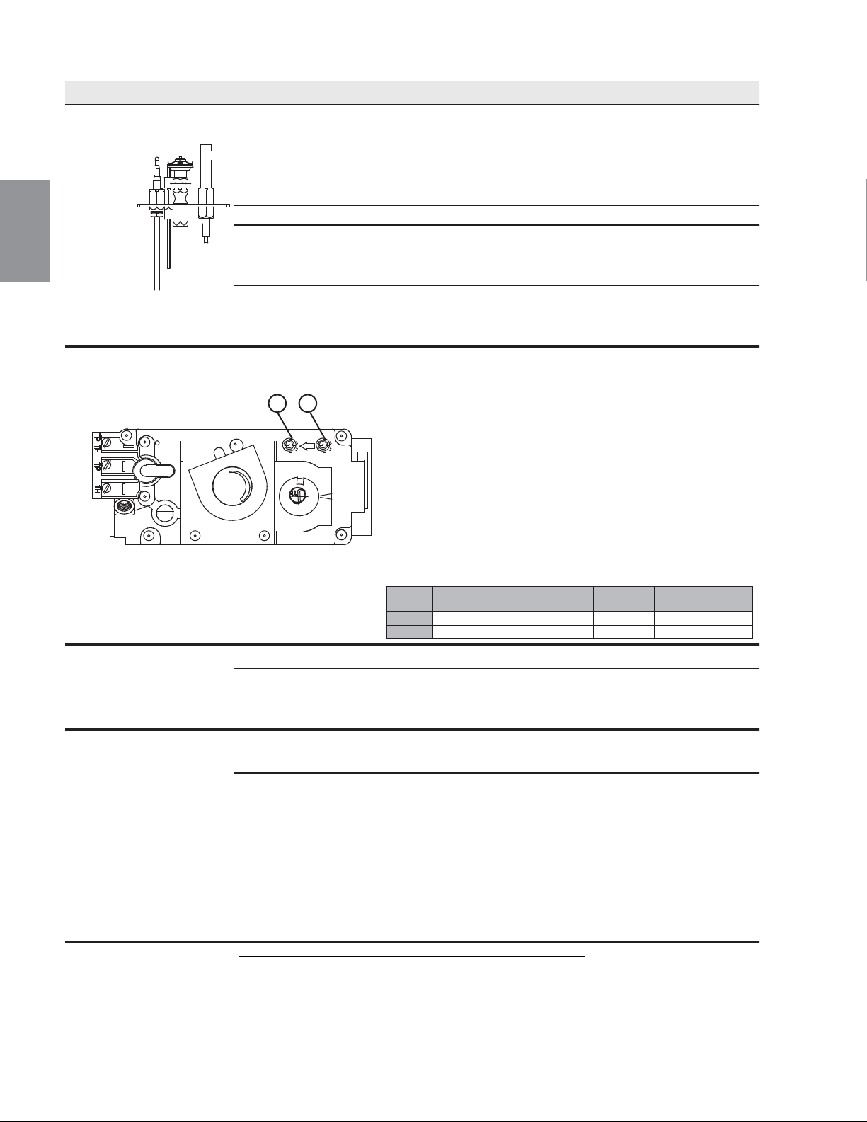
156
W415-1401 / C / 03.19.15
FR
SYMPTÔME PROBLÉME SOLUTIONS
La veilleuse ne
s’allume pas.
Aucune étincelle au brûleur de
la veilleuse.
- Vérifi ez si la veilleuse peut être allumée avec une allumette.
- Vérifi ez si le fi l est raccordé au bouton-poussoir d’ignition.
- Vérifi ez si le bouton-poussoir d’ignition doit être resserré.
- Remplacez le fi l si son isolant est brisé ou effi loché
- Remplacez l’électrode si l’isolateur de céramique est craque
ou brisé.
- Remplacez le bouton-poussoir d’ignition.
Plus de propane. - Remplissez le réservoir.
La longueur de l’étincelle est
incorrecte.
- La longueur de l’étincelle devrait être de 0,150” (3,8mm) à
1,175” (4,5mm) entre la pointe de l’électrode et le brûleur
de la veilleuse. Pour que l’électrode soit bien placée, serrez
l’écrou avec les doigts et tournez 1/4 de tour de plus..
Pas de gaz au brûleur de la
veilleuse.
- Vérifi ez si la soupape manuelle est ouverte.
- Vérifi ez si l’injecteur de la veilleuse est bloqué.
- Remplacez la soupape.
- Contactez le fournisseur de gaz.
Les fl ammes sont
réguliérement trop grandes
ou trop petites. Il y a des
dépots de carbone.
La pression du gaz est trop
faible ou trop forte.
- Vérifi ez la pression:
- Pour vérifi er la pression d’arrivée, tournez deux ou trois
fois la vis (A) vers a gauche, puis emboîtez le tube du
manométre sur la pointe d’essai
. Le manométre doit indiquer
la pression comme décrit sur le diagramme ci-dessous.
Assurez-vous que le brûleur prinicpal fonctionne à ‘HI’.
- La pression de sortie peut être vérifi ée de la même façon
en utilisant la vis(B). Le manométre doit indiquer la pression
comme décrit sur la diagramme ci-dessous. Assurez-vous
que le brûleur prinicpal fonctionne à ‘HI’.
- APRÉS AVOIR PRIS LA LECTURE DES PRESSIONS,
ASSUREZ-VOUS DE TOURNER FERMEMENT LA VIS
VERS LA DROITE POUR SCELLER NE SERREZ PAS
TROP FORT.
- Vérifi ez pour des fuites en appliquant une solution d’eau
savonneuse.
Les fl ammes sont trés
actives.
La porte est entrouverte. - Serrez les vis qui retiennent la porte en place.
Forte action de ventilation. - Assurez-vous que l’évacuation est adéquatement scellée.
- Si aucune plaque de restriction n’est fournie avec l’appareil,
étranglez la sortie de l’évacuation avec la plaque de
restriction listée à la section ‘ACCESSOIRES’.
Du carbone se dépose sur
la vitre les bûches ou les
parois de la chambre de
combustion.
Le volet d’air est bloqué. - Assurez-vous que l’ouverture du volet d’air n’est pas bloquée
par des fi bres ou autres obstructions.
- Vérifi ez si les bûches sont positionnées correctment.
- Augmentez l’ouverture du volet d’air pour augmenter le
volume d’air primaire.
- Vérifi ez le débit d’alimentation: vérifi ez que la pression
du collecteur et la grandeur de l’injecteur sont telles que
spécifi ées sur la plaque d’homologation.
- Vérifi ez si les joints de la porte ne sont pas brisés ou
manquants et qu’ils sont étanches.
- Vérifi ez si les deux conduits d’event ne sont pas troués et
qu’ils sont bien scellés à tous les joints.
- Vérifi ez si l’élévation minimale par pied (métre) est conforme
pour toute évacuation horizontale.
42.3_2E
P
I
P
I
L
O
T
N
O
L
O
T
H
I
L
O
F
F
O
A
B
Pression
Gaz Naturel
(pouces)
Gaz Naturel
(millibars)
Propane
(pouces)
Propane
(millibars)
Arrivée 7” (min.4,5”) 17,4 mb (min.11,2mb) 13” (min.11”) 32,4 mb (min.27,4mb)
Sortie 3,5” 8,7 mb 10” 24,9 mb
VEILLEUSE
THERMOCOUPLE
THERMOPILE

157
W415-1401 / C / 03.19.15
FR
SYMPTÔME PROBLÈME SOLUTIONS
42.3_3
Une pellicule
blanche ou grise se
forme.
Le souffre du combustible
se dépose sur la vitre, les
bûches ou les parois de la
chambre de combustion.
- Nettoyez la vitre avec un nettoyeur recommandé.
- NE PAS NETTOYER LORSQU’ELLE EST CHAUDE.
- Si vous ne nettoyez pas les dépôts régulièrement, la vitre risque de
rester marquée en permanence.
On détecte l’odeur
des gaz de
combustion dans la
pièce; maux de tête.
L’appareil refoule les gaz
de combustion dans la
pièce.
- Assurez-vous de l’étanchéité de la buse d’évacuation amovible.
- Vérifi ez tous les joints scellés et la plaque d’expansion.
- Vérifi ez si la cheminée ne serait pas bloquée.
- Vérifi ez si la cheminée est installée selon les codes du bâtiment.
- La pièce est sous pression négative; augmentez l’apport d’air frais.
- Vérifi ez le joint d’étanchéité du couvercle d’évacuation.
L’interrupteur mural
est à « OFF » ; le
brûleur principal
s’allume lorsque le
bouton du gaz est
tourné à « ON ».
L’interrupteur mural est
raccordé à l’envers.
- Raccordez à l’endroit.
L’interrupteur mural
cause un court-circuit.
- Remplacez.
Le fi l de l’interrupteur mural
cause un court-circuit.
- Vérifi ez si le fi l est bien mis à la terre; réparez ou remplacez le fi l.
Soupape défectueuse. - Remplacez.
NAPOLÉON® garantit ses produits contre les défauts de fabrication à l’acheteur d’origine seulement. L’enregistrement de la garantie n’est pas
nécessaire. Fournissez simplement une preuve d’achat ainsi que le modèle et le numéro de série afi n d’effectuer une réclamation de garantie. Napoléon®
se réserve le droit de demander à son représentant d’inspecter tous produits ou pièces avant d’honorer toute réclamation. L’achat doit avoir été fait par
l’entremise d’un détaillant NAPOLÉON® autorisé et sous réserve des conditions et limitations suivantes :
La couverture de la garantie débute à partir de la date d’installation originale.
Cette garantie du fabricant n’est pas transférable et ne peut être prolongée ou étendue par aucun de nos représentants quelle qu’en soit la raison.
L’appareil au gaz doit être installé par un installateur ou entrepreneur qualifi é. L’installation doit être faite conformément aux instructions d’installation
incluses avec le produit et à tous les codes d’incendie et de construction locaux et nationaux.
Cette garantie limitée ne couvre pas les dommages causés par un mauvais usage, un manque d’entretien, un accident, des altérations, des abus ou de la
négligence et l’installation de pièces d’autres fabricants annulera cette garantie.
Cette garantie limitée ne couvre pas non plus les égratignures, les bossellements, la corrosion ou la décoloration causés par une chaleur excessive, des
produits d’entretien chimiques et abrasifs ou l’écaillage des pièces en porcelaine émaillée, le bris par manipulation des bûches PHAZER® et des braises.
NAPOLÉON® garantit à vie ses brûleurs en acier inoxydable contre les défauts de fabrication et de matériau sous réserve des conditions suivantes :
durant les dix premières années, NAPOLÉON® remplacera ou réparera selon notre option les pièces défectueuses gratuitement. Après les dix premières
années, NAPOLÉON® fournira les brûleurs de rechange à 50 % du prix de détail courant.
Au cours de la première année seulement, cette garantie s’applique à la réparation ou au remplacement des pièces garanties dont les matériaux ou la
fabrication sont défectueux à la condition que le produit ait été utilisé conformément aux instructions de fonctionnement et dans des conditions normales.
Après la première année, concernant cette Garantie à Vie Limitée du Président, NAPOLÉON® peut, à sa discrétion, se libérer entièrement de toutes
obligations en ce qui concerne cette garantie en remboursant à l’acheteur d’origine le prix de gros de toute pièce garantie qui est défectueuse.
NAPOLÉON® ne sera pas responsable de l’installation, de la main-d’oeuvre ou autres dépenses relatives à la réinstallation d’une pièce garantie et de
telles dépenses ne sont pas couvertes par cette garantie.
Nonobstant toutes les dispositions contenues dans cette Garantie à Vie Limitée du Président, la responsabilité de NAPOLÉON® sous cette garantie est
défi nie comme ci-dessus et elle ne s’appliquera à aucun dommage accidentel, consécutif ou indirect.
Cette garantie défi nit l’obligation et la responsabilité de NAPOLÉON® en ce qui concerne l’appareil au gaz Napoléon®. Toute autre garantie énoncée ou
implicite en ce qui concerne ce produit, ses composants ou accessoires est exclue.
NAPOLÉON® n’endosse ni n’autorise aucun tiers à assumer en son nom, toute autre responsabilité concernant la vente de ce produit. NAPOLÉON®
ne sera pas responsable d’une surchauffe, des refoulements, des déversements causés par des conditions environnementales telles que des toits, des
bâtiments, la proximité d’arbres, de collines, de montagnes, une ventilation ou des évents inadéquats, une confi guration d’évacuation excessive, un apport
d’air insuffi sant ou des pressions négatives qui peuvent ou non être causés par des systèmes mécaniques tels que les ventilateurs d’évacuation, les
fournaises, les sécheuses de linge, etc.
Tout dommage causé à l’appareil, à la chambre de combustion, à l’échangeur de chaleur, aux garnitures plaquées ou autres composants par l’eau, les
dommages causés par les intempéries, de longues périodes d’humidité, la condensation, des produits chimiques ou produits d’entretien nuisibles ne
seront pas la responsabilité de NAPOLÉON®.
Toutes les pièces remplacées en vertu de la politique de Garantie à vie limitée du Président ne peuvent faire l’objet que d’une seule réclamation.
Durant les dix premières années, NAPOLÉON® remplacera ou réparera les pièces défectueuses qui sont couvertes par la garantie à vie limitée à sa
discrétion gratuitement. Après les dix premières années, NAPOLÉON® fournira les pièces de rechange à 50 % du prix de détail courant.
Toutes les pièces remplacées au titre de la garantie seront couvertes pour une période de 90 jours à partir de leur date d’installation.
Le fabricant peut exiger que les pièces défectueuses ou les produits soient retournés ou que des photos numériques soient fournies pour valider la
réclamation. Les produits retournés doivent être expédiés port payé au fabricant pour une inspection en usine. Si un produit est déclaré défectueux, le
fabricant le réparera ou le remplacera.
Avant d’expédier votre appareil ou les pièces défectueuses, votre détaillant doit obtenir un numéro d’autorisation. Toute marchandise expédiée à notre
usine sans autorisation sera refusée et retournée à l’expéditeur.
Les coûts d’expédition ne sont pas couverts par cette garantie.
Des frais de service supplémentaires peuvent être appliqués si vous cherchez à obtenir des services au titre de la garantie auprès d’un détaillant. Les
indemnités de main-d’oeuvre au titre de la garantie s’appliquent uniquement pour le remplacement d’une pièce garantie. Les frais de déplacement, de
tests de diagnostic, d’expédition et autres frais afférents ne sont pas couverts par cette garantie.
2.1C
Les produits Napoléon® sont fabriqués conformément aux normes strictes du Certifi cat d’Assurance de la
Qualité mondialement reconnu ISO 9001 : 2008.
Les produits Napoléon® sont conçus avec des composants et des matériaux de qualité supérieure, assemblés par des artisans
qualifi és qui sont fi ers de leur travail. Le brûleur et le montage de la soupape subissent un test de détection de fuite et d’allumage à
une station de test de qualité. Une fois assemblé, chaque appareil est soigneusement inspecté par un technicien qualifi é avant d’être
emballé pour garantir que vous, le client, recevez le produit de qualité dont vous vous attendez de Napoléon®.
Les matériaux suivants et la fabrication de votre nouveau appareil au gaz Napoléon® sont garantis contre les défauts tant que vous en
êtes le propriétaire. Ceci couvre : la chambre de combustion, l’échangeur de chaleur, le brûleur en acier inoxydable, les bûches PHAZER®
et les braises, les roches, la vitre en céramique (cassure thermique seulement), les pièces plaquées or contre le ternissement, les
composants en porcelaine émaillée et les moulures d’extrusion en aluminium.*
Les composants électriques (110V et millivolt) et les pièces soumises à l’usure tels que les souffl eries, les soupapes de gaz, l’interrupteur
thermique, les interrupteurs, l’installation électrique, les télécommandes, l’allumeur, les joints d’étanchéité et l’assemblage de la veilleuse
sont couverts et NAPOLÉON® fournira gratuitement les pièces de rechange durant la première année de la garantie limitée.*
Les coûts de main-d’oeuvre relatifs aux réparations garanties sont couverts gratuitement durant la première année. Cependant, les travaux
de réparation nécessitent l’approbation préalable d’un représentant autorisé de la compagnie. Les coûts de main-d’oeuvre à la charge
de Napoléon® sont basés sur un programme de tarifs prédéterminé et tout travail de réparation doit être accompli par l’entremise d’un
représentant autorisé Napoléon®.
* La fabrication de chaque modèle varie. La garantie s’applique uniquement aux composants disponibles avec votre appareil.
GARANTIE À VIE LIMITÉE DU PRÉSIDENT DES APPAREILS AU GAZ NAPOLÉON®
CONDITIONS ET LIMITATIONS
TOUTES LES SPÉCIFICATIONS ET LES CONCEPTIONS SONT SUJETTES À MODIFICATIONS SANS PRÉAVIS EN RAISON DES
AMÉLIORATIONS CONSTANTES APPORTÉES AUX PRODUITS. NAPOLÉON® EST UNE MARQUE DE COMMERCE DÉPOSÉE DE
WOLF STEEL LTÉE.
COMME EXIGÉ PAR LE MINISTÈRE DE L’ÉNERGIE AUX ETATS-UNIS, 10 CFR SÉPARE 430, LA GARANTIE EST VIDE SI CE
PRODUIT EST UTILISÉ AVEC UN THERMOSTAT. CECI S’APPLIQUE AU PRODUIT SEULEMENT INSTALLÉ AUX ETATS-UNIS.
158
W415-1401 / C / 03.19.15
FR
22.0 GARANTIE
Date
43.1
Problèmes particuliersTravail effectuéNom du technicienDétaillant
Historique d’entretien Wolf Steel
Cet appareil doit être entretenu annuellement selon son usage.
23.0 HISTORIQUE D’ENTRETIEN
159
W415-1401 / C / 03.19.15
FR
Autres produits Napoléon
®
Foyers encastrés • Grils au charbon de bois • Foyers au gaz • Cascades d’eau
Poêles à bois • Produits HVAC • Foyers électriques • Foyers extérieurs • Grils à gaz de qualité
Foyers / Chauffage et Climatisation / Grils composez : 514-737-6294
napoleonproducts.com
7200, Route Transcanadienne, Montréal, Québec H4T 1A3
24 Napoleon Road, Barrie, Ontario, Canada L4M 0G8
214 Bayview Drive, Barrie, Ontario, Canada L4N 4Y8
103 Miller Drive, Crittenden, Kentucky, USA 41030