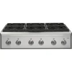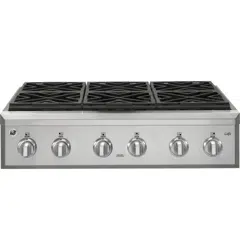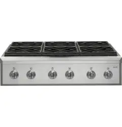
Professional Rangetop
CGU366, CGU486
31-2000816 Rev. 0 11-20 GEA
Questions? Visit cafeappliances.com.
Installation Instructions
TM
Contents
Safety Information ....................................................... 2
Design Information
Product Dimensions and Clearances ............................ 4
Installation Information
High Altitude Kit ............................................................. 7
Materials Provided ......................................................... 7
Materials Required (not provided) ................................. 7
Tools Required .............................................................. 7
Installation
Remove Packaging ....................................................... 8
Cut the Countertop Opening ......................................... 9
Install Rangetop .......................................................... 10
Conversion to Propane (LP) Gas or Natural Gas ....... 10
Gas Supply .................................................................. 11
Electrical Connections ................................................. 12
Check Burners ............................................................. 12
Check Surface Burners ............................................... 12
Finalize Installation ...................................................... 13
When All Hookups Are Completed.............................. 13
UX12BS36PSS, UX12BS48PSS Accessory Installation
Optional Accessories—12” High Backsplash
Tools and Materials Required ..................................... 14
Install 12” Backsplash ................................................. 14
UXADBS36PSS, UXADBS48PSS Accessory Installation
Accessories—30” To 36” Adjustable Backsplash)
Tools and Materials Required ..................................... 15
Install the Wall Support Panels ................................... 15
Install Cover Panels .................................................... 16
English • Français • Español
2 31-2000816 Rev. 0
Safety Information
READ AND SAVE THESE INSTRUCTIONS
IN THE COMMONWEALTH OF MASSACHUSETTS
■ This product must be installed by a licensed plumber
or gas fitter.
■ Whenusingballtypegasshut-offvalves,theyshall
betheT-handletype.
■ Aflexiblegasconnector,whenused,mustnotexceed
5 feet.
WARNING
FIRE OR EXPLOSION HAZARD
Iftheinformationinthismanualisnotfollowedexactly,
afireorexplosionmayresultcausingpropertydamage,
personal injury or death.
Installation must be performed by a qualified installer.
Read these instructions completely and carefully.
Installationofthisrangemustconformwithlocalcodes,
orintheabsenceoflocalcodes,withtheNational
FuelGasCode,ANSIZ223.1/NFPA.54,latestedition.
InCanada,installationmustconformwiththecurrent
NaturalGasInstallationCode,CAN/CGA-B149.1or
thecurrentPropane(LP)InstallationCode,CAN/CGA-
B149.2,andwithlocalcodeswhereapplicable.This
rangehasbeendesign-certifiedbyCSAInternational
accordingtoANSIZ21.1,latesteditionandCanadian
GasAssociationaccordingtoCAN/CGA-1.1latestedition.
When installing a gas appliance the use of
oldflexibleconnectorscancausegasleaksand
personalinjury.AlwaysuseaNEWflexibleconnector.
Leak testing of the appliance shall be conducted
according to the manufacturer instructions.
The range must be electrically grounded in accordance
withlocalcodesor,intheabsenceoflocalcodes,in
accordancewiththeNationalElectricalCode(ANSI/
NFPA70,latestedition).InCanada,electricalgrounding
mustbeinaccordancewiththecurrentCSAC22.1
CanadianElectricalCodePart1and/orlocalcodes.See
Electrical Connections in this section.
Donotinstallthisproductwithanaircurtainhoodor
otherrangehoodthatoperatesbyblowingairdownon
thecooktop.Thisairflowmayinterferewithoperationof
thegasburnersresultinginfireorexplosionhazard.
Have a question or need assistance with your appliance? Try the Café website 24 hours a day, any day of the
year! You can also shop for more great Café products and take advantage of all our on-line support services
designed for your convenience. In the US: cafeappliances.com. (In Canada, cafeappliances.ca.)
31-2000816 Rev. 0 3
Safety Information
READ AND SAVE THESE INSTRUCTIONS
BEFORE YOU BEGIN
Read these instructions completely and carefully.
■ IMPORTANT — Save these instructions
for local inspector’s use.
■ IMPORTANT — Observe all governing
codes and ordinances.
■ IMPORTANT — Remove all packing
material and literature from oven before connecting
gas and electrical supply to range.
■ IMPORTANT — To avoid damage to
yourcabinets,checkwithyourbuilderorcabinet
suppliertomakesurethatthematerialsusedwill
notdiscolor,delaminateorsustainotherdamage.
Thisovenhasbeendesignedinaccordancewith
the requirements of UL and CSA International and
complieswiththemaximumallowablewoodcabinet
temperatures of 194°F (90°C).
■ Note to Installer — Be sure to leave these
instructionswiththeconsumer.
■ Note to Consumer —Keeptheseinstructionswith
yourOwner’sManualforfuturereference.
■ Servicer — The electrical diagram is in an envelope
attached to the back of the range.
■ Proper installation is the responsibility of the
installer.
■ Product failure due to improper installation is not
coveredunderwarranty.
■ ForCaféPartsandAccessories,visitourwebsiteat
cafeappliances.com.
(InCanada, cafeappliances.ca.)
■Ifyoureceivedadamagedrangetops,youshould
contact your dealer.
IF SOLD OUTSIDE THE U.S. AND
CANADA
WARNING
Ifyouwishtousethisproductwith
Liquefied Petroleum (LP) gas containing greater
than10%butane,youmustpurchasethebutane
conversionkit#CXBUPR01Toorder,pleasecall
1.888.664.8403 or 1.787.276.4051. Failure to do so
mayresultincarbonmonoxideorfirehazard.
VENT HOOD COMBINATIONS
A suitable overhead vent hood is required for models
withagrillandisrecommendedforallothermodels.
Duetothehighheatcapacityofthisunit,particular
attentionshouldbepaidtothehoodandductwork
installation to assure it meets local building codes.
Clearancestohorizontalsurfacesabovetherange,
measuredtothecookingsurfacearebelow.Failureto
comply may result in fire hazard.
■Installationswithoutahoodrequire48”minimumto
combustibles.
■Acustomhoodinstallationwithexposedhorizontal
combustiblessurfacesmusthaveanAuto-Onfeature.
■Forotherinstallationswithahood,refertohood
installation instructions for specific hood clearances.
CAUTION
Theserangetopsareextremely
heavy.Somedisassemblywillreducetheweight
considerably.Duetotheweightandsizeofthe
rangetop and to reduce the risk of personal injury or
damage to the product:
TWO PEOPLE ARE REQUIRED FOR PROPER
INSTALLATION OF RANGETOPS.
THREE PEOPLE ARE REQUIRED FOR PROPER
INSTALLATION OF 48” RANGETOPS.
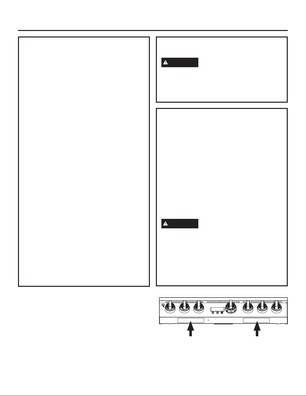
Rating Label Location Rating Label Location
4 31-2000816 Rev. 0
Design Information
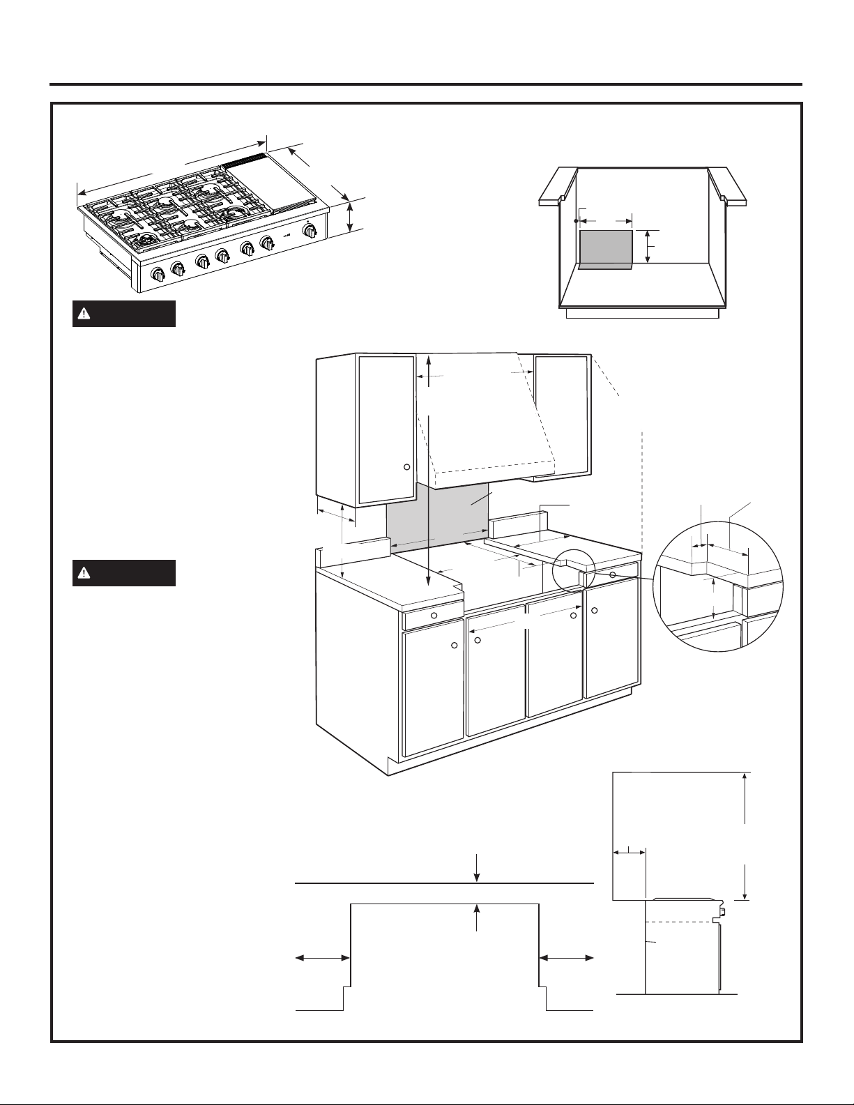
PRODUCT DIMENSIONS AND CLEARANCES FOR 48” MODELS
ADDITIONAL CLEARANCES:
Allow12”minimumclearanceto
anadjacentwalloneachside.
Working areas adjacent to
the rangetop should have 18”
minimumclearancebetween
countertop and the bottom of the
wallcabinet.
Forislandinstallation,maintain
2-1/2in.minimumfromcutoutto
back edge of countertop and 3 in.
minimum from cutout to side edges
ofcountertop(seetopview).
WARNING
Installations
withoutahoodrequire48”minimum
to combustibles. A custom hood
installationwithexposedhorizontal
combustible surfaces must have
anAuto-Onfeature.Refertohood
installation instructions for specific
hood clearances.
The surface of the entire back
wallabovetherangeandbelow
thehoodmustbecoveredwitha
non-combustiblematerialsuchas
metal,ceramictile,brick,marble
or other stone.
CAUTION
To prevent
drafts from affecting burner
operation,sealallopeningsin
floor under appliance and behind
appliancewall.
** As defined in the National Fuel Gas
Code(ANSIZ223.1/CSAB149.1,
CurrentEdition).Clearancesfromnon-
combustible materials are not part of the
ANSIZ21.1/CSA1.1scopeandarenot
certified by CSA. Clearances less than
12” must be approved by local codes
and/ortheauthorityhavingjurisdiction.
Universal Utility Locations
2”
17”
16”
Locate gas
inlet on back
walloron
floor 2” from
backwall.
22-3/4”Min.
2-1/2”
8”
7/8”
12” Minimum
Each Side
46-1/4”
*Theopeningbetween
a 4” high backsplash
mustbe48”toallow
the rangetop to slide
backagainstthewall.
16”Max.
18” Min.
48” Minimum
to Combustibles
48” Minimum
12” Minimum to
Adjacent Wall
48” *
Non-combustiblematerial**
48”
12” Minimum to
Combustibles or 0”
tonon-combustible
material above the
cooking surface **
0”
Clearance
Back
3” Min. 3” Min.
2-1/2”Min.
Island Cutout
TopView
48” Min. to
Combustibles
8-1/2”Height
47-7/8”Width
27-5/8”to
Front of
Bullnose
31-2000816 Rev. 0 5
Design Information
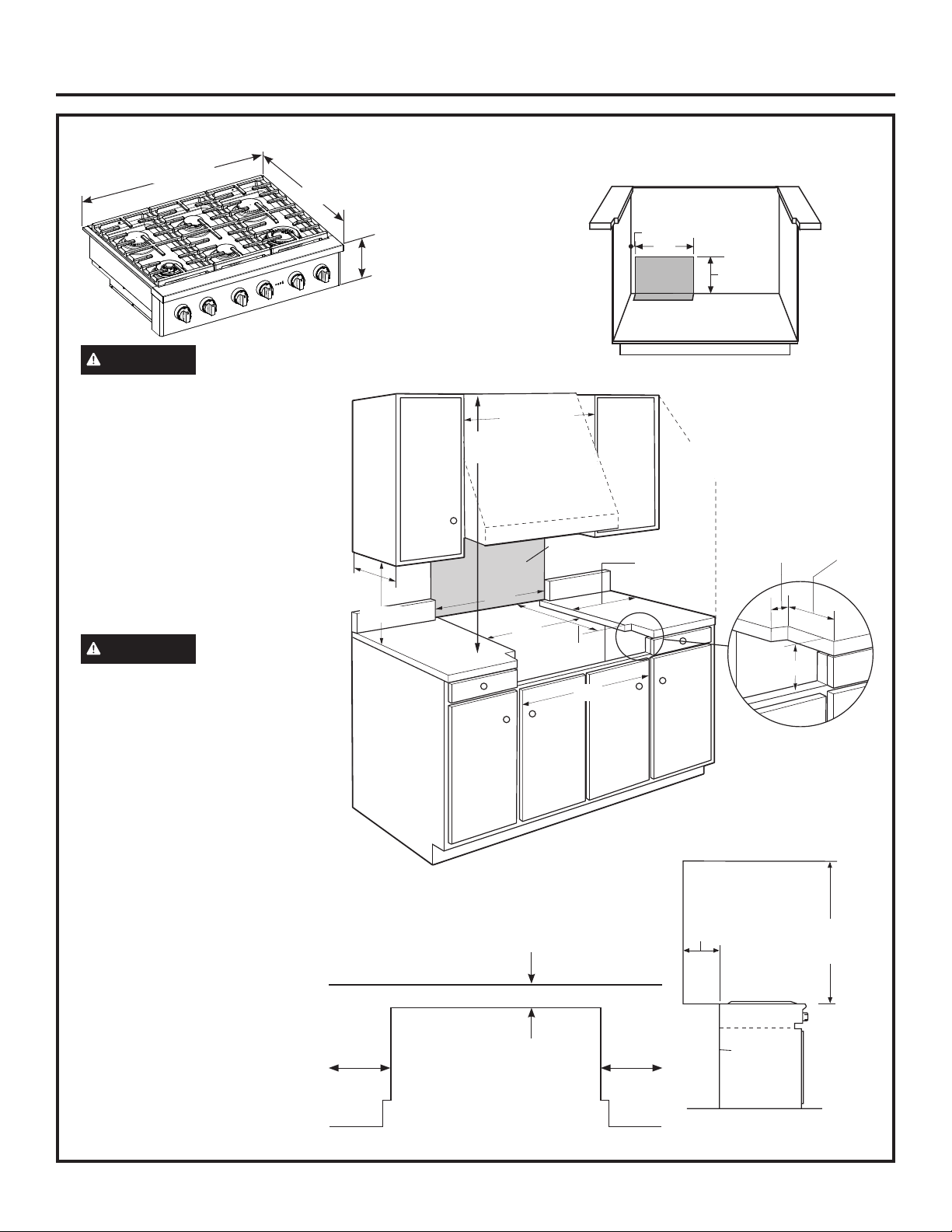
PRODUCT DIMENSIONS AND CLEARANCES FOR 36” MODELS
ADDITIONAL CLEARANCES:
Allow12”minimumclearanceto
anadjacentwalloneachside.
Working areas adjacent to
the rangetop should have 18”
minimumclearancebetween
countertop and the bottom of the
wallcabinet.
Forislandinstallation,maintain
2-1/2in.minimumfromcutoutto
back edge of countertop and 3 in.
minimum from cutout to side edges
ofcountertop(seetopview).
WARNING
Installations
withoutahoodrequire48”minimum
to combustibles. A custom hood
installationwithexposedhorizontal
combustible surfaces must have
anAuto-Onfeature.Refertohood
installation instructions for specific
hood clearances.
The surface of the entire back
wallabovetherangeandbelow
thehoodmustbecoveredwitha
non-combustiblematerialsuchas
metal,ceramictile,brick,marble
or other stone.
CAUTION
To prevent
drafts from affecting burner
operation,sealallopeningsin
floor under appliance and behind
appliancewall.
** As defined in the National Fuel Gas
Code(ANSIZ223.1/CSAB149.1,
CurrentEdition).Clearancesfromnon-
combustible materials are not part of the
ANSIZ21.1/CSA1.1scopeandarenot
certified by CSA. Clearances less than
12” must be approved by local codes
and/ortheauthorityhavingjurisdiction.
Universal Utility Locations
2”
17”
16”
Locate gas
inlet on back
walloron
floor 2” from
backwall.
22-3/4”Min.
2-1/2”
8”
1/2”
12” Minimum
Each Side
35”
*Theopeningbetween
a 4” high backsplash
mustbe36”toallow
the rangetop to slide
backagainstthewall.
16”Max.
18” Min.
48” Minimum
to Combustibles
12” Minimum to
Adjacent Wall
36” *
Non-combustiblematerial**
36”
48” Min. to
Combustibles
0”
Clearance
Back
3” Min. 3” Min.
Island Cutout
TopView
2-1/2”Min.
12” Minimum to
Combustibles or 0”
tonon-combustible
material above the
cooking surface **
8-1/2”
Height
35-7/8”Width
27-5/8”to
Front of
Bullnose
36” Minimum
6 31-2000816 Rev. 0
Design Information
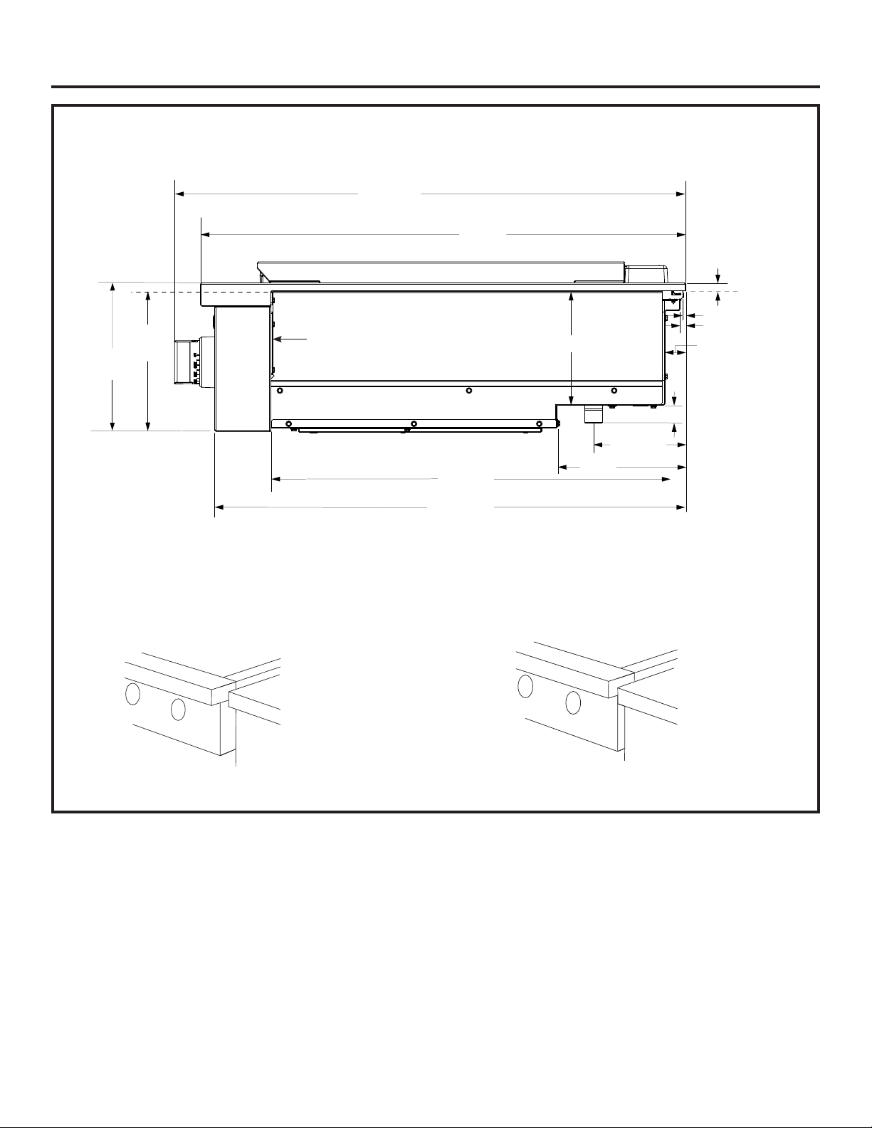
PRODUCT DIMENSIONS AND CLEARANCES
48” and 36” Rangetop Models
Controlpanelprojectsforwardsfrom
standard depth cabinets.
Frontofdeepcabinetscanalignwith
control panel beveled edge.
†
Includetheoverhangofthereartrimwhencountertopcontinuesbehindtheproduct.
Theoverhangisdecorativeonly.Theweightoftherangetopisfullysupportedbythesidetrims.
**Maximumcountertopcutoutdepthfromthebackofthereartrimtothebackedgeofchamferat
thesidesofthecontrolpanel-typically,themaximumcountertopcutoutdepth(fronttoback).
Minimumcountertopcutoutdepthis25-1/4”.
Rangetop
1/2”AboveAdjacent
Countertops
1/2”AboveAdjacent
Countertops
Rangetop
29-1/8”
To front of control knobs
27-5/8”
To front of bullnose
8”
Countertop
Level
6-1/2”
1-3/16”
†
3/16”
11/32”
7-1/4”
1”
23-5/8”
5-1/4”
To pipe
stub center
1/2”
Countertop
level
**26-7/8”
To front of
control panel
8-1/2”
Height
Rear finished edge of the
control panel
31-2000816 Rev. 0 7
Installation Information
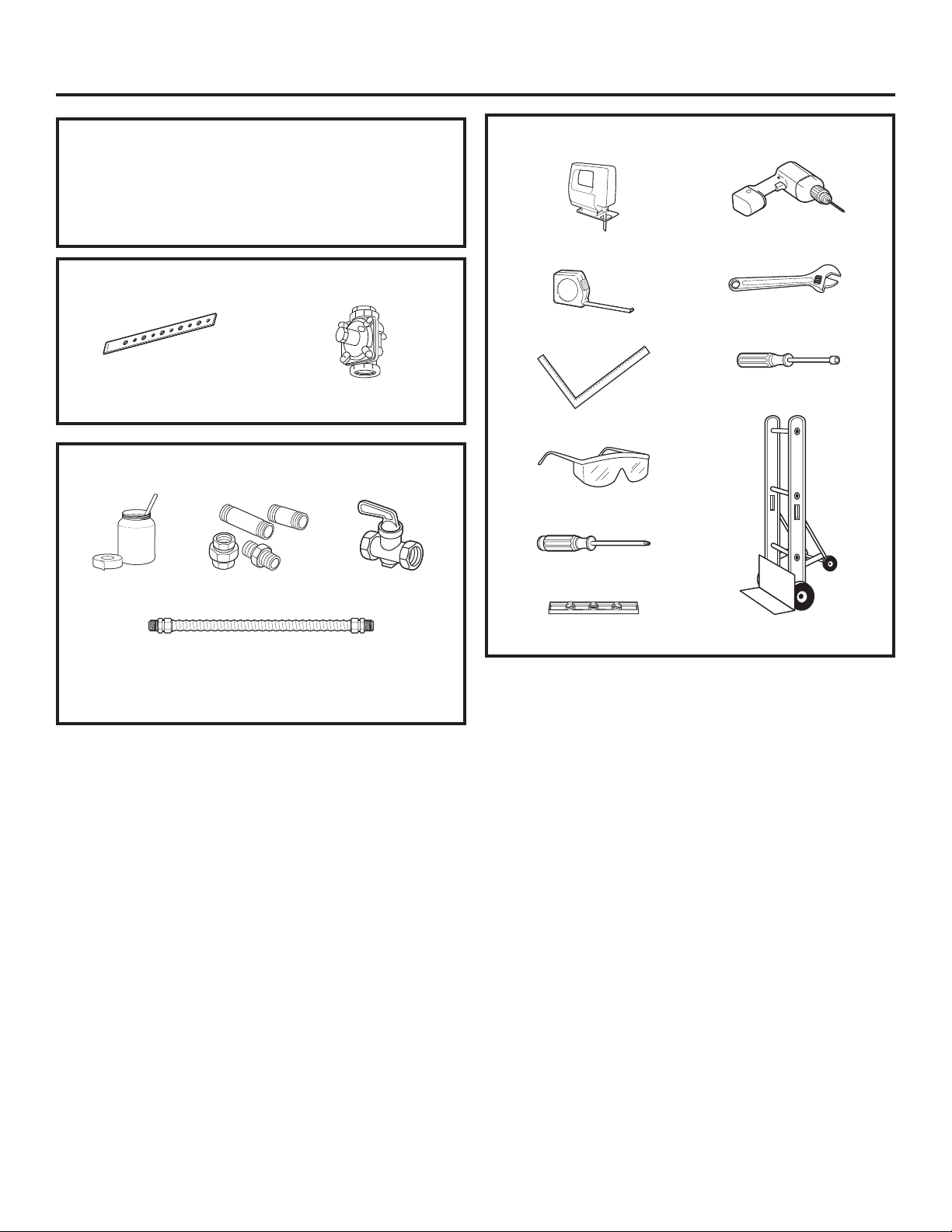
TOOLS REQUIRED
MATERIALS REQUIRED (not provided)
Adjustable Wrench
1/4”DriverorWrench
Safety Glasses
Drill and
Appropriate Bits
Measuring Tape
Phillips#2Screwdriver
SaberSaw
Carpenter’s Square
Level
Hand Truck
Shut-OffValvePipe Fittings
5-footmaximumlength,5/8”O.D.CSA-
approvedflexiblemetalgassupply
NOTE:Purchasenewflexibleline;donot
usepreviouslyusedflexiblegasline.
Pipe Thread
Sealant
MATERIALS PROVIDED
Regulator
Hold-DownStrap
INSTALLATION AT HIGH ALTITUDE
Over6000ft,productconfiguredfornaturalgasor
propane requires installation of kit (WB28X39728
for natural gas and WB28X39729 for propane gas).
Followtheinstructionsincludedwiththekit.
8 31-2000816 Rev. 0
Installation
1
REMOVE PACKAGING
CAUTION
Stand clear. The ends of the cut metal
bandingmaysnaptowardyou.
■Cutthemetalbanding.
■Removepackagingtapeandfoam.Disposeof
packaging materials properly.
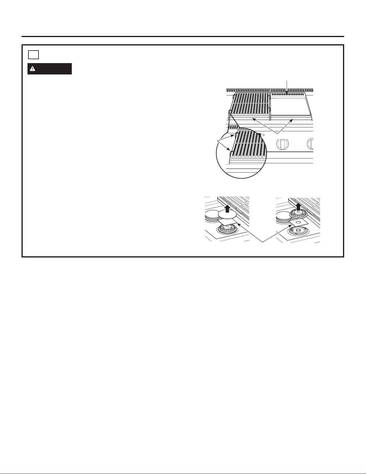
■Removegrill/griddlecovers,grillgrateandburner
grates.
■Liftoutcast-irongriddlefluecover,greasetroughs
and pads.
■Cutthetiesholdingthegrillgratetothegrillframe.
■Liftoffburnercapsandremovefoampad,thenliftoff
burner heads and remove foam pad.
Remove Foam Pads
Griddle Flue Cover
Grease Troughs
Ties
31-2000816 Rev. 0 9
Installation
2
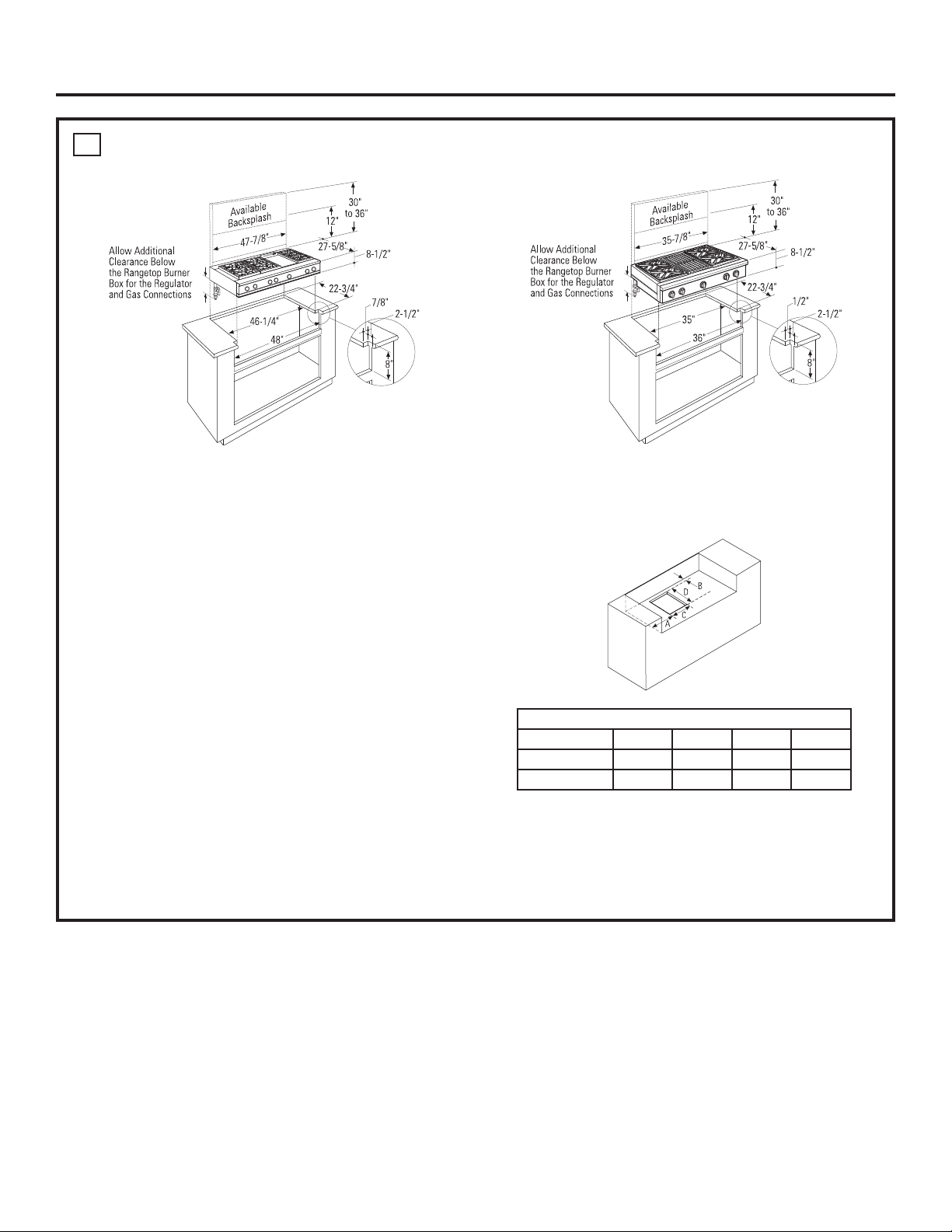
CUT THE COUNTERTOP OPENING
Measurecarefullywhencuttingthecountertop.Make
sure sides of the opening are parallel.
■Allow8”freespacebelowthetopsurfaceofthe
countertop.
■Allowadditionalclearancesbelowtheburnerbox
to install the regulator and make house supply
connections.Usea90°elbowtoroutethegas
connectionsandlimitinterferencewithdrawersor
other cabinetry features.
■Theserangetopsaredesignedtohangfromthe
countertop by their side flanges.
■Smoothanyroughedgesonthecountertopbefore
installing the rangetop.
– Formica countertop edges must be finished.
The countertop must be strong enough to support the
weightoftherangetop.
Cutout Opening with False Bottom
■Youcanconstructthecutoutwithafalsebottomto
conceal the bottom of the rangetop.
– Buildthefalsebottomusingasolidmaterial;cuta
7-1/2”x11-1/8”holeintheleftrearcornerforthe
gasinletandpowercordclearances.
48”widemodelsaredesignedtofitin48”orwiderbasecabinets 36”widemodelsaredesignedtofitin36”orwiderbasecabinets
Dimensions
A (Dia.) B C D
36” Rangetop 7-3/8” 1-1/2” 7-1/2” 11-1/8”
48” Rangetop 8-1/4” 1-1/2”
7-1/2”
11-1/8”
10 31-2000816 Rev. 0
4
CONVERSION TO PROPANE (LP)
OR NATURAL GAS
The pressure regulator and the burner orifices are
set for natural gas at the factory. To operate the
rangetopwithpropane(LP),theregulatorandburner
orifices must be converted. The conversion must be
performed by a qualified propane (LP) gas installer.
Keep these instructions and all orifices in case you
wanttoconvertbacktonaturalgas.
Installation
3
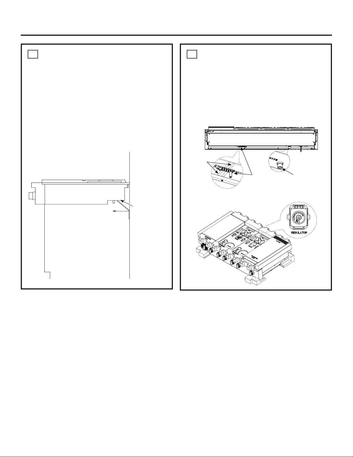
INSTALL RANGETOP
■Slidetherangetopintotheopening.Makesurethe
rangetop is evenly seated and supported.
■Ahold-downstrapwithscrewsisprovidedtosecure
therangetoptotherearorsidecabinetwalls.
■Removethehold-downstrapfromthebackofthe
rangetop. Attach one end of the strap to the back of
the rangetop.
■Securetheotherendofthestrapashighas
possibletothecabinetbackwalloradjacent
cabinet. Keep the strap as short as possible for
better security.
Back Wall
Hold-Down
Strap
Location and
Attachment
Tape
Propane
Conversion
Kit
Gas Inlet
31-2000816 Rev. 0 11
Installation
5
GAS SUPPLY
WARNING
Fire Hazard: Do not use a flame to
check for gas leaks.
WARNING
ExplosionHazard:Donotexceed
25ft-lbsoftorquewhenmakinggaslineconnections.
Overtightening may damage the pressure regulator
resultinginfireorexplosionhazard.
Gas Pressure Regulator
Youmustusethegaspressureregulatorsupplied
withthisrangetop.Forproperoperationstheinlet
pressuretotheregulatorshouldbeasfollows:
Natural Gas:
Minimum pressure: 6” of Water Column
Maximumpressure:13”ofWaterColumn
Propane (LP) Gas:
Minimum pressure: 11” of Water Column
Maximumpressure:13”ofWaterColumn
If you are not sure about the inlet pressure contact
local gas supplier.
Shut off the main gas supply valve before
disconnecting the old rangetop and leave it off
until the new hook-up has been completed. Don’t
forget to relight the pilot on other gas appliances
when you turn the gas back on.
Because hard piping restricts movement of the
rangetop,theuseofaCSAInternational-certified
flexiblemetalapplianceconnectorisrecommended
unlesslocalcodesrequireahard-pipedconnection.
Ifthehardpipingmethodisused,carefullyalign
thepipe;therangetopcannotbemovedafterthe
connection is made.
Topreventgasleaks,putpipethreadsealanton,or
wrappipethreadtapewithTeflon*aroundallmale
(external)pipethreads.
A. Install provided pressure regulator directly to the
gasinletpipeoftherangetop.Refertothearrow
onthebackoftheregulatorforgasflowdirection.
Ensurethefrontoftheregulatorisfacingtowards
thecabinetfront,easilyaccessiblethroughthe
cabinet doors.
B. Installamanualshut-offvalveinthegaslineina
location easily accessible through the cabinet doors.
C. Whenallconnectionshavebeenmade,ensureall
gas controls are in the off position and turn on the
main gas supply valve. Use a liquid leak detector
at all joints and connections to check for leaks in
the system.
*Teflon: Registered trademark of DuPont
5
GAS SUPPLY (cont.)
Whenusingpressuresgreaterthan1/2psigto
pressuretestthegassupplysystemoftheresidence,
disconnecttherangetopandindividualshut-offvalve
from the gas supply piping. When using pressures
of1/2psigorlesstopressuretestthegassupply
system,simplyisolatetherangetopfromthegas
supplysystembyclosingtheindividualshut-offvalve.
Whencheckingforproperoperationoftheregulator,
the inlet pressure must be at least 1” greater than the
operating (manifold) pressure as given on rating label
of product.
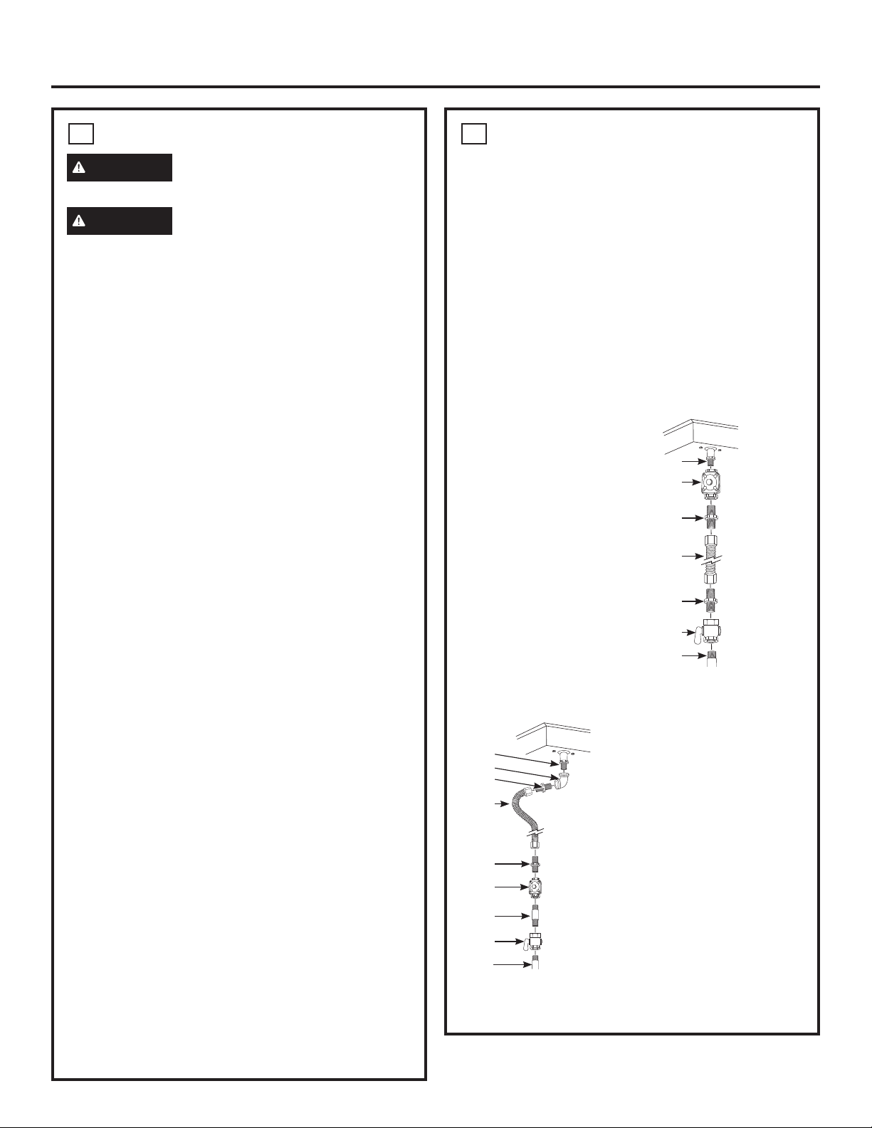
CONNECTOR HOOKUP
TYPICALINSTALLATIONWITHNO
OBSTRUCTION BELOW RANGETOP
A
B
C
D
F
G
E
A. 3/4”NPTmalepipe
thread
B. Regulatorprovidedwith
unit:
• Outlet-3/4”NPT
female pipe thread
• Inlet-1/2”NPTfemale
pipe thread
C. Adapter
D. Flexibleconnector
E. Adapter
F. Manualshut-offvalve
G. Gaspipe1/2”or3/4”
A. 3/4”NPTmalepipethread
B. Elbow
C. Adapter
D. Flexibleconnector(allows
passagethroughcabinetwall)
E. Adapter
F. Regulatorprovidedwithunit:
• Outlet-3/4”NPTfemale
pipe thread
• Inlet-1/2”NPTfemalepipe
thread
G. Gas pipe
H. Manualshut-offvalve
I. Gaspipe1/2”or3/4”
ALTERNATE INSTALLATION WITH
OBSTRUCTION BELOW RANGETOP
A
B
C
D
F
G
E
I
H
12 31-2000816 Rev. 0
Installation
6
ELECTRICAL CONNECTIONS
WARNING
Shock Hazard: This appliance must
be properly grounded. Failure to do so can result in
electric shock.
ElectricalRequirements-120-volt,60Hertz,properly
groundeddedicatedcircuitprotectedbya15-ampor
20-ampcircuitbreakerortimedelayfuse.
NOTE:Useofautomatic,wireless,orwiredexternal
switchesthatshutoffpowertotheappliancearenot
recommended for this product.
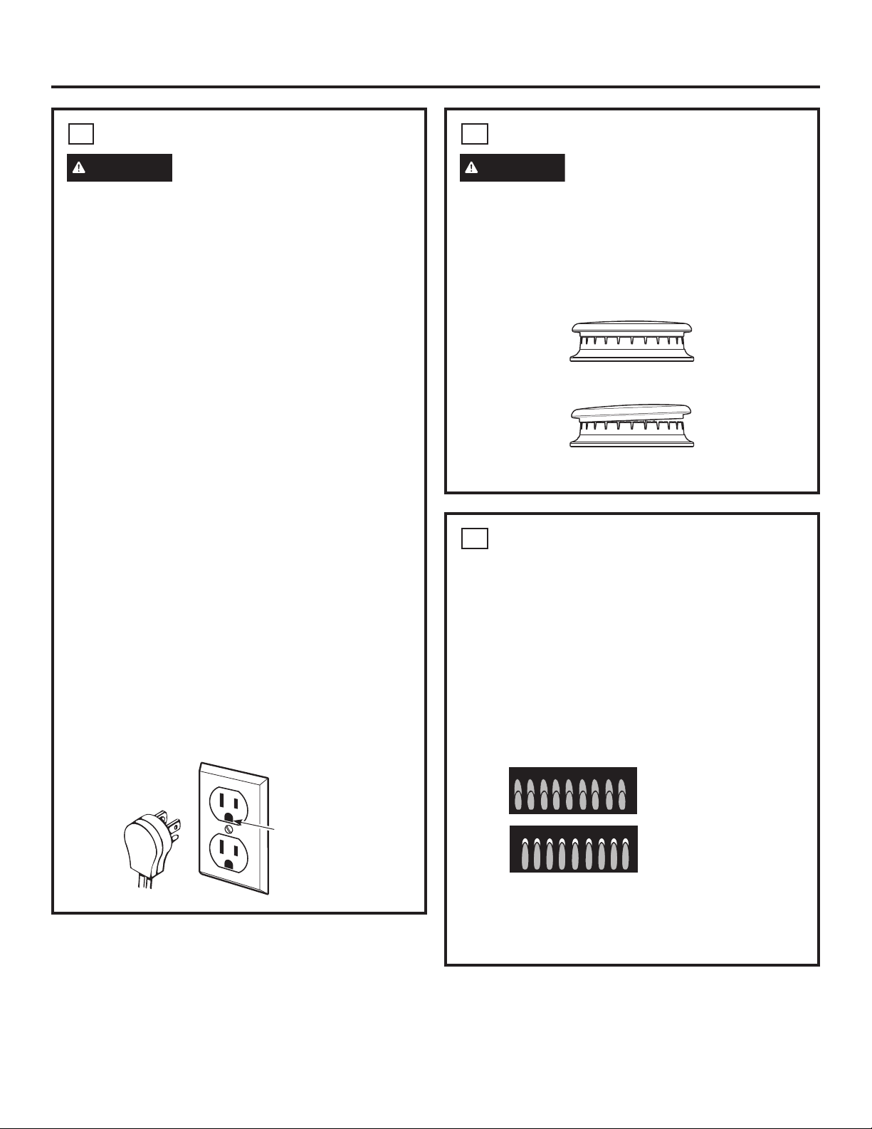
Grounding
Thepowercordofthisapplianceisequippedwith
athree-prong(grounding)plugwhichplugsintoa
standardthree-pronggroundingwallreceptacleto
minimize the possibility of electric shock hazard from
this appliance.
Thecustomershouldhavethewallreceptacleand
circuit checked by a qualified electrician to make sure
the receptacle is properly grounded.
Whereastandardtwo-prongwallreceptacleis
encountered,itisthepersonalresponsibilityand
obligationofthecustomertohaveitreplacedwitha
properlygroundedthree-prongwallreceptacle.
DONOT,UNDERANYCIRCUMSTANCES,CUTOR
REMOVE THE THIRD (GROUND) PRONG FROM
THE POWER CORD. DO NOT USE AN ADAPTER.
DO NOT USE AN EXTENSION CORD.
Ground Fault Circuit Interrupters (GFCI’s) are not
required or recommended for gas range receptacles.
Performanceoftherangewillnotbeaffectedif
operatedonaGFCI-protectedcircuitbutoccasional
nuisance tripping of the GFCI breaker is possible.
Ensure proper
groundexists
before use
7
CHECK BURNERS
WARNING
FireorExplosionHazard:Donot
operatetheburnerwithoutallburnerpartsinplace.
A. Burners-Placesurfaceburnersintocorresponding
positions on cooktop.
B. Caps-Placecapsonpropersizeburner.
C. Grates-Theleftandrightgratesare
interchangeable. Place the grates on the cooktop.
8
CHECK SURFACE BURNERS
Push and turn a knob to the LITE position. A clicking
sound indicates proper operation of the ignition
system.Whenlightinganyburner,sparkswillappear
atallburnersbutgasflowsfromonlytheoneselected.
Onceairispurgedfromthesupplyline,burnershould
lightwithin4seconds.Afterburnerlights,rotatethe
knob out of the LITE position. Try each burner in
succession until all burners have been checked.
Quality of Flames
Determine the quality of flames visually. Normal
burner flames should look like (A) or (B).
Long,brightyellowflamesarenotnormal.Normal
flamesmayshowsignsofanorangetintwhenwell
heated or signs of flickering orange due to particles in
the gas or air.
(A) Soft blue flames—
Normal for natural gas
(B) Yellow tips on
outer cones—
Normal for propane (LP) gas
Burner Cap Not Properly Seated
Burner Cap Properly Seated
31-2000816 Rev. 0 13
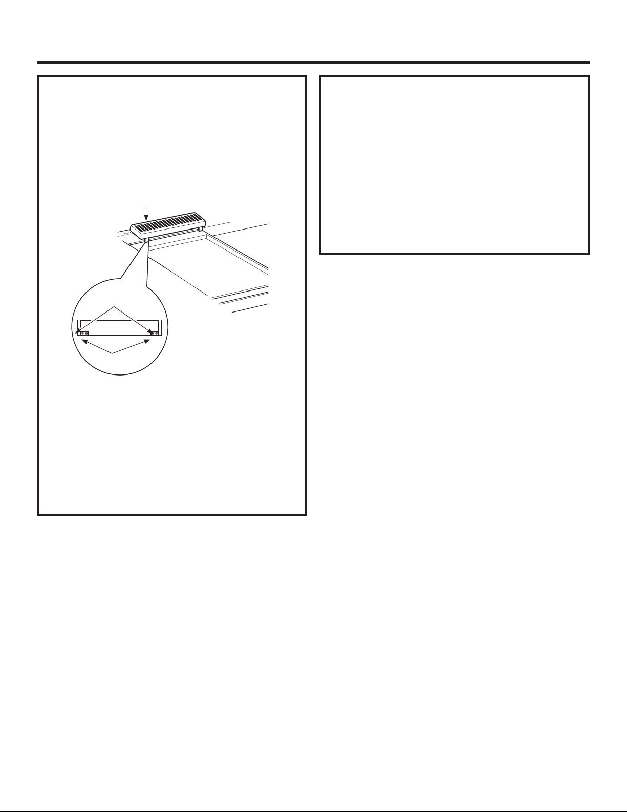
Installation
FINALIZE INSTALLATION
Place the burner grates over the burners. The grates
should be seated and should not rock.
Thegriddleissecuredwithscrews.Itisdesignedto
be stationary and should not be removed.
Thegriddlehastwolevelingscrewsbeneaththerearflue
cover that can be used to adjust to the desired slope.
Thetwoinnerscrewsareclampingscrewsfor
securingthegriddleinplace.Loosenthesetwoscrews
beforeleveling.Donotremovethesetwoscrews.
Thetwoouterscrewsarelevelingscrews.Donot
removethesetwoscrews.Theycanbeturnedtolevel
thegriddleortoprovideaforwardslopetohelpgrease
andoilsdrainawayfromthefoodbeingcooked.
Afterlevelingthegriddle,hand-tightentheclamping
screws;donotover-tighten.
WHEN ALL HOOKUPS ARE
COMPLETED
Make sure all controls are left in the off position. Make
suretheflowofcombustionandventilationairtothe
range is unobstructed.
Check that all packing materials and tape have been
removed.Thiswillincludetapeonmetalpanelunder
controlknobs(ifapplicable),adhesivetape,wire
ties,cardboard,andprotectiveplastic.Failureto
remove these materials could result in damage to the
appliance once the appliance has been turned on and
surfaces have heated.
Griddle Flue Cover
ClampingScrews
LevelingScrews

14 31-2000816 Rev. 0
OPTIONAL ACCESSORIES—12” HIGH BACKSPLASH
UX12BS36PSS, UX12BS48PSS Accessory Installation
This kit provides for the installation of a 12” high
backsplash for 36” Professional Ranges and Rangetops.
TOOLS AND MATERIALS REQUIRED
■Glovestoprotectagainstsharpedges
■T-15and#2Phillips
screwdrivers
■Drillwith3/32”and
9/64”bits
■Safetyglasses
■Level
■Pencil
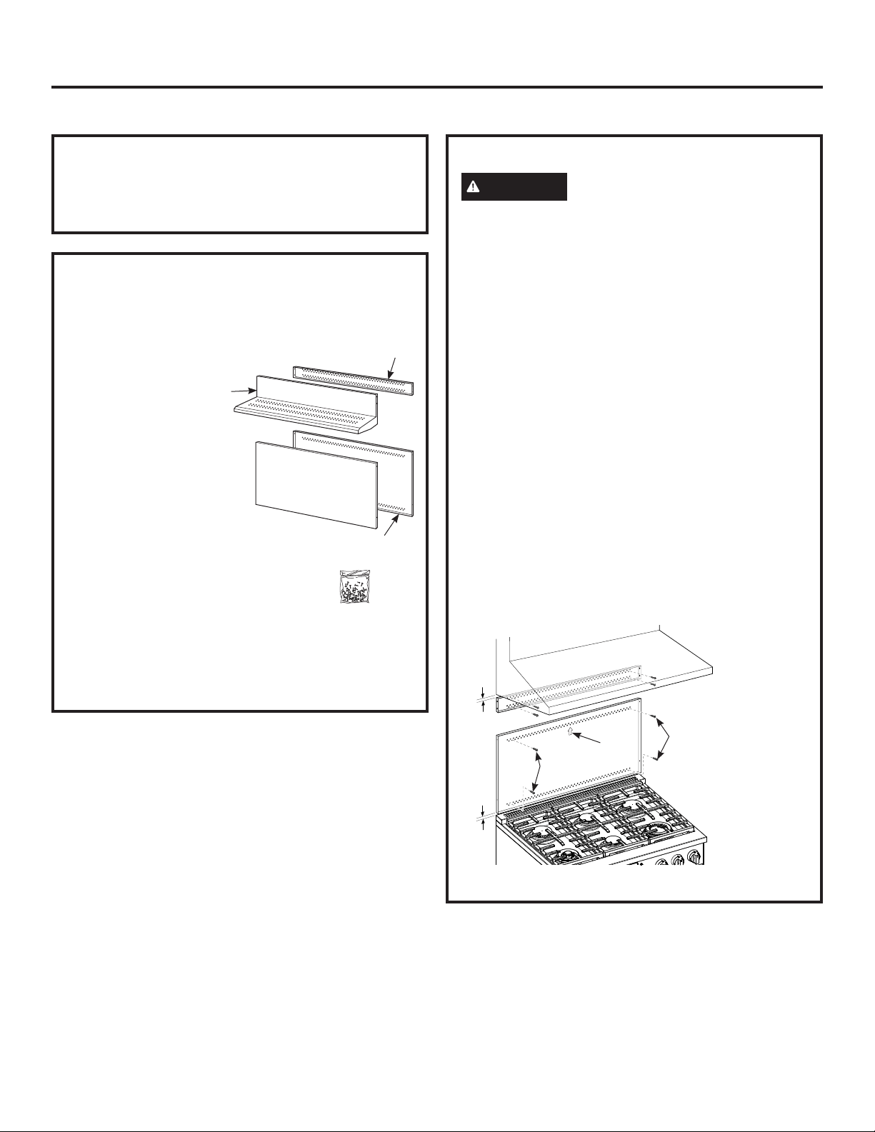
This Kit Includes
■Wallsupportpanel
■Coverpanel
■Hardwarepackagewith
–5StainlessSteelTorx15
#8self-tappingscrews
–5Phillips#2panheadwood
#10screws
INSTALL 12” BACKSPLASH
WARNING
This backsplash must be securely
fastenedtothewall.Failuretodosocouldresultin
damage or personal injury.
■Installandleveltherangeorrangetopandthe
range hood according to the installation instructions.
■Removethebacksplashpackagingandprotective
film.
■Usealeveltopencilahorizontallineonthewall,1/8”
abovetherangeorrangetop.The1/8”gapallowsthe
coverpaneltooverlapthewallsupportpanel.
■Locatewallstudsoneachside.Wherestudsarenot
available,plantousewallanchors(notprovided).
■Alignthewallsupportpanelonthemarked
horizontal line and centered left to right.
■Thewallsupportpanelmustbesecuredtothewall
atall4corners.Usewoodscrews(provided)orwall
anchors (not provided) to secure the support panel
tothewall.
■Placethecoverpaneloverthewallsupportpanel
andsecurewithTorxscrews(provided).Install2
screwsoneachside.
Install4WoodScrews
Wall Support Panel
Cover Panel
Hardware
Package
Install4WoodScrews
InstallT-15
Screws
Wall
Support
Panel
Wall Support
Panel
Cover Panel
Center
Arrow
1/8”
31-2000816 Rev. 0 15
UXADBS36PSS, UXADBS48PSS Accessory Installation
ACCESSORIES—30” TO 36” ADJUSTABLE BACKSPLASH (not included)
■Thisbacksplashadjuststofitthespacebetween
thetopoftherangeandthebottomofthehood,
from30”Min.to36”Max.height.
■Maximumshelfload-bearingweightis40lbs.
TOOLS AND MATERIALS REQUIRED
■Glovestoprotectagainstsharpedges
■T-15and#2Phillipsscrewdrivers
■Drillwith3/32”and9/64”bits
■Safetyglasses
■Level
■Pencil
This Kit Includes
■Topwallsupport
■Bottomwallsupport
■Topcoverwithshelf
■Bottomcover
■Hardwarepackagewith
–9StainlessSteelTorx15#8
self-tappingscrews
–9Phillips#2panheadwood
#10screws
– 3 Stainless Steel #2 truss head
#10screws(foralternate
installation method)
INSTALL THE WALL SUPPORT PANELS
WARNING
Thewallsupportpanelsmustbe
securelyfastenedtothewall.Failuretodosocould
result in damage or personal injury.
IMPORTANT: This backsplash is designed to cover
thewallbetweenthebottomofthehoodandthetopof
the range. The vent hood should be installed over the
rangetop or range before installing this backsplash.
■InstallandleveltheRange/Rangetopaccordingto
the product installation instructions.
■Removebacksplashpackagingandprotectivefilm.
■Locatewallstudsoneachside.Wherestudsarenot
available,plantousewallanchors(notprovided).
■Usealeveltopencil2horizontallinesonthewall,
one1/8”belowtheventhoodandtheother1/8”
abovetheRange/Rangetop.This1/8”spaceallows
thecoverpanelstooverlapthewallsupports.
■Securethetopwallsupportpaneltothewallwith4
woodscrews,throughtheoutermoststuds.
■Use4woodscrewstosecurethebottomwallsupport
panel. The center slot should be positioned at the top.
Thegapbetweenthetopandbottomsupportpanels
willbecoveredbythetopcoverwithshelf.
Hardware
Package
Top Cover
withShelf
Bottom Cover
Bottom Wall Support
Top Wall
Support
1/8”
Secure the
top panel to
thewallwith4
woodscrews
1/8”
Secure the
bottom panel to
thewallwith4
woodscrews
Wood
Screws
Center
Arrow
Wood
Screws

16 31-2000816 Rev. 0
UXADBS36PSS, UXADBS48PSS Accessory Installation
INSTALL COVER PANELS
See alternate method if side access is blocked.
■Holdthebottomcoveroverthebottomsupport
whiledrivingonescrew(provided)intoeachside.
■Placethetopcoverwithshelfoverthetopwall
support.Ifyouhaveaccesstothesides,securethe
panelwithtwoscrewsoneachside.
■Securethetopcoverwithshelftothetopsupport
withscrewsthroughthefrontofthepanel,atthetop
corners.Useonescrewoneachside.
INSTALL COVER PANELS (cont.)
ALTERNATE METHOD: When side access is blocked
■Installbottomcoveroverthebottomsupportwhile
drivingonescrewintoeachside.
■Holdtopcoverinplacewhilemarkingscrewlocations,
justbelowshelfsupportandontobottomcover.
■Removetheshelfanddrilla9/64”diameterholein
thepencil-markedlocations.
■Mountthetopcoveroverthetopsupportand
securethefrontcoverwithscrewsthroughthe
drilled holes on each side.
■Installscrewsthrougheachtopcorner.
MarkScrew
Locations for
Alternate Method
ACCESSORIES—30” TO 36” ADJUSTABLE BACKSPLASH (not included) (Cont.)
Install
Screw
Cover Panel
Install
Screw
InstallCornerScrews
InstallScrew
on Each Side
Shelf
InstallScrewinTopCorneronEachSide

31-2000816 Rev. 0 17
Notes

18 31-2000816 Rev. 0
Notes

31-2000816 Rev. 0 19
Notes

20 31-2000816 Rev. 0
NOTE: Whileperforminginstallationsdescribedinthisbook,
safetyglassesorgogglesshouldbeworn.
NOTE: Product improvement is a continuing endeavor at
GEAppliances.Therefore,materials,appearanceand
specificationsaresubjecttochangewithoutnotice.
PrintedinMexico