Loading ...
Loading ...
Loading ...
SERVICE AND A USTMENTS
CAUTION: BEFORE PERFORMING ANY SERVICE OR ADJUSTMENTS:
o Release controlbar.
° Make sure the blade and all moving parts have completely stopped.
= Disconnect spark plug wire from spark plug and place where it cannot come in contact with plug.
LAWN MOWER
TO ADJUST CUTTING HEIGHT
See "TO ADJUST CUTTING HEIGHT" in the Operation
section of this manual,.
REAR DEFLECTOR
,The rear deflector, attached between the rear wheels of
your lawn mower, is provided to minimize the possibility
that objects wit! be thrown out the rear of the lawn mower
into the operator's mowing positlon_ If the rear deflector
becomes damaged, it should be replaced_
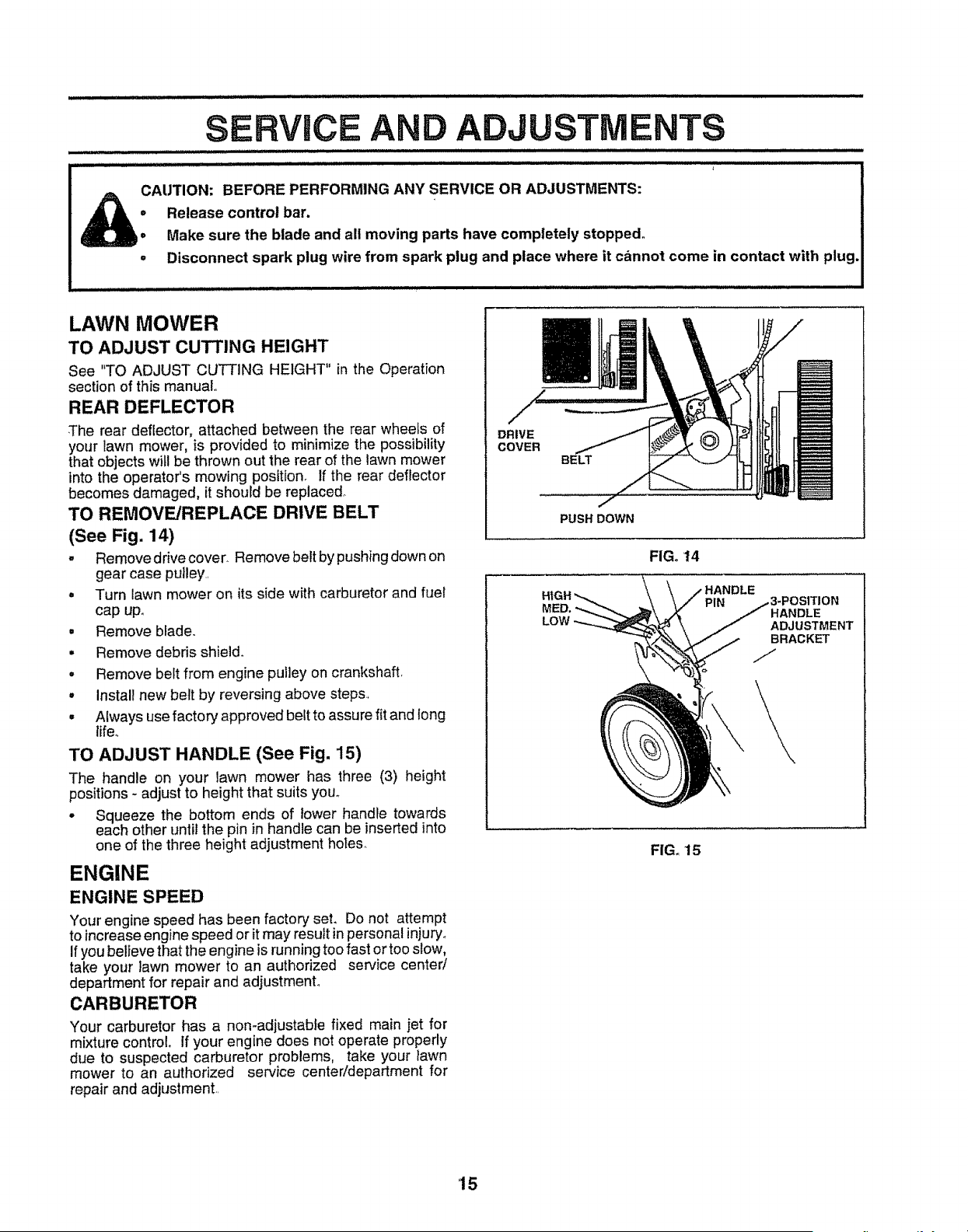
TO REMOVE/REPLACE DRIVE BELT
(See Fig, 14)
. Remove drive cover. Remove belt by pushing down on
gear case pulley..
• Turn lawn mower on its side with carburetor and fuel
cap upo
= Remove blade.
• Remove debris shield_
• Remove belt from engine pulley on crankshaft_
• Install new belt by reversing above steps.,
• Always use factory approved belt to assure fit and long
life.
TO ADJUST HANDLE (See Fig, 15)
The handle on your lawn mower has three (3) height
positions - adjust to height that suits you°
° Squeeze the bottom ends of lower handle towards
each other until the pin in handle can be inserted into
one of the three height adjustment holes.
ENGINE
ENGINE SPEED
Your engine speed has been factory set, Do not attempt
to increase engine speed or itmay result in personal injury.
Ifyou believe that the engine is running too fast or too slow,
take your lawn mower to an authorized service center/
department for repair and adjustment°
CARBURETOR
Your carburetor has a non-adjustable fixed main jet for
mixture control, if your engine does not operate properly
due to suspected carburetor problems, take your lawn
mower to an authorized service center!department for
repair and adjustment..
m
DRIVE
COVER
BELT
MP
PUSH DOWN
FIG. 14
LOW
HANDLE
PIN
HANDLE
ADJUSTMENT
BRACKET
FIG. 15
15
Loading ...
Loading ...
Loading ...