
INSTRUCTION MANUAL
P755AXA-1
P755ASV-1
P755ASN-1
P755ASG-1
P755ASBL-1
P755ASB-1
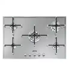
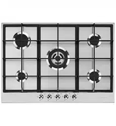
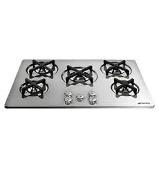
SMEG GAS COOKING HOBS

ENGLISH 3 - 26
Thank you for choosing our product.
We advise you to read this manual carefully. It contains
all
necessary
instructions for
maintaining unaltered the appearance and functional qualities of the oven.
Contents
1. INSTRUCTIONS FOR
USE
................................................................ 4
2. SAFETY
PRECAUTIONS
................................................................... 6
3. ENVIRONMENTAL
RESPONSIBILITY
............................................... 8
4. DESCRIPTION OF CONTROLS......................................................... 9
5. USING THE HOB.............................................................................. 10
6. CLEANING AND
MAINTENANCE
.................................................... 14
7. POSITIONING IN THE COUNTER TOP .......................................... 16
8. ELECTRICAL CONNECTION........................................................... 20
9. GAS
CONNECTION
......................................................................... 21
10. ADAPTATION TO DIFFERENT TYPES OF GAS ........................... 23
INSTRUCTIONS FOR THE USER: these instructions contain user
recommendations, a description of the controls and the correct
procedures for cleaning and maintenance of the appliance.
INSTRUCTIONS FOR THE INSTALLER: these are intended for the
authorised person who must install the appliance, set it functioning and
carry out an inspection test.
@
Further information about the products can be found at www.smeg.com
3
General
instructions
1. INSTRUCTIONS FOR USE
THIS MANUAL IS AN INTEGRAL PART OF THE APPLIANCE. IT MUST BE KEPT IN ITS
ENTIRETY AND IN AN ACCESSIBLE PLACE FOR THE WHOLE WORKING LIFE OF
THE HOB. WE ADVISE YOU TO READ THIS MANUAL AND ALL THE INFORMATION IT
CONTAINS CAREFULLY BEFORE USING THE HOB. ALSO KEEP
THE
SERIES
OF NOZZLES PROVIDED. INSTALLATION MUST BE CARRIED OUT BY
QUALIFIED PERSONNEL IN ACCORDANCE WITH THE REGULATIONS IN
FORCE. THIS APPLIANCE IS INTENDED FOR HOUSEHOLD USE AND COMPLIES
WITH
THE
EEC
DIRECTIVES CURRENTLY IN FORCE. THE APPLIANCE HAS BEEN
BUILT TO CARRY OUT THE FOLLOWING FUNCTION: COOKING AND HEATING
FOODS; ALL OTHER USES ARE TO BE CONSIDERED IMPROPER.
THE MANUFACTURER CANNOT BE HELD LIABLE FOR USE OTHER THAN AS
INDICATED
.
IF THE APPLIANCE IS INSTALLED ON BOATS OR IN CARAVANS, DO NOT USE IT AS
A ROOM HEATER.
DO NOT USE THIS APPLIANCE FOR HEATING ROOMS.
THIS APPLIANCE IS MARKED ACCORDING TO EUROPEAN DIRECTIVE 2002/96/EC
ON WASTE ELECTRICAL
AND
ELECTRONIC
EQUIPMENT (WEEE).
THIS DIRECTIVE DETERMINES THE STANDARDS FOR THE COLLECTION AND
RECYCLING OF WASTE ELECTRICAL AND ELECTRONIC EQUIPMENT APPLICABLE
THROUGHOUT THE EUROPEAN UNION.
BEFORE THE APPLIANCE IS PUT INTO OPERATION, ALL PROTECTIVE FILMS
MUST BE REMOVED.
SUITABLE HEAT-PROOF GLOVES SHOULD BE WORN FOR ALL OPERATIONS.
DO NOT USE STEEL SPONGES AND SHARP SCRAPERS AS THEY WILL
DAMAGE THE SURFACE.
USE NORMAL NON-ABRASIVE PRODUCTS, INCLUDING WOODEN OR
PLASTIC UTENSILS IF NECESSARY.
RINSE
THOROUGHLY
AND DRY
USING A SOFT CLOTH OR A MICROFIBRE CLOTH.
DO
NOT
LEAVE THE APPLIANCE UNATTENDED DURING COOKING OPERATIONS
WHERE FATS OR OILS COULD BE RELEASED.
FATS AND OILS
MAY
CATCH
FIRE.
4
General
instructions
ALWAYS CHECK THAT THE CONTROL KNOBS ARE IN
THE
(OFF) POSITION
WHEN YOU FINISH USING THE HOB.
NEVER PLACE PANS WITH BOTTOMS WHICH ARE NOT PERFECTLY FLAT
AND SMOOTH ON THE COOKING HOB RACKS.
NEVER USE CONTAINERS WHICH PROJECT BEYOND THE OUTSIDE EDGE OF THE
HOB.
5
General
instructions
2. SAFETY PRECAUTIONS
REFER TO THE INSTALLATION INSTRUCTIONS FOR THE SAFETY REGULATIONS
FOR ELECTRIC OR GAS APPLIANCES AND VENTILATION FUNCTIONS.
IN YOUR INTERESTS AND FOR YOUR SAFETY IT HAS BEEN ESTABLISHED BY LAW
THAT THE INSTALLATION AND SERVICING OF ALL ELECTRICAL APPLIANCES IS TO
BE CARRIED OUT BY QUALIFIED PERSONNEL IN ACCORDANCE WITH THE
REGULATIONS IN FORCE.
OUR APPROVED INSTALLERS GUARANTEE A SATISFACTORY JOB.
GAS OR ELECTRICAL APPLIANCES MUST ALWAYS BE DISCONNECTED BY
SUITABLY SKILLED PEOPLE.
BEFORE CONNECTING THE APPLIANCE TO THE POWER GRID, CHECK THE DATA
ON THE PLATE AGAINST THE DATA FOR THE GRID ITSELF.
THE IDENTIFICATION PLATE CONTAINING THE TECHNICAL DATA, SERIAL NUMBER
AND BRAND NAME IS IN A VISIBLE POSITION UNDER THE CASING.
DO NOT REMOVE THE PLATE ON THE CASING FOR ANY REASON.
BEFORE CONNECTING THE APPLIANCE, ENSURE THAT IT IS SET TO THE TYPE
OF GAS THAT IT WILL BE SUPPLIED WITH, CHECKING THE LABEL APPLIED UNDER
THE CASING.
BEFORE CARRYING OUT INSTALLATION/MAINTENANCE WORK, MAKE SURE THAT
THE APPLIANCE IS NOT CONNECTED TO THE POWER GRID.
THE PLUG TO BE CONNECTED TO THE POWER SUPPLY CABLE AND ITS SOCKET
MUST BE OF THE SAME TYPE AND CONFORM TO THE REGULATIONS IN FORCE.
THE SOCKET MUST BE ACCESSIBLE AFTER THE APPLIANCE HAS BEEN BUILT IN.
NEVER DISCONNECT THE PLUG BY PULLING ON THE CABLE.
IF THE POWER SUPPLY CABLE IS DAMAGED, CONTACT THE
TECHNICAL SUPPORT SERVICE IMMEDIATELY AND THEY WILL REPLACE IT.
IT IS OBLIGATORY FOR ALL ELECTRICAL EQUIPMENT TO BE EARTHED
ACCORDING TO THE METHODS LAID DOWN BY SAFETY REGULATIONS.
IMMEDIATELY AFTER INSTALLATION, CARRY OUT A BRIEF INSPECTION TEST,
FOLLOWING THE INSTRUCTIONS BELOW. SHOULD THE APPLIANCE NOT
FUNCTION, DISCONNECT IT FROM THE POWER SUPPLY AND CALL THE NEAREST
TECHNICAL SUPPORT CENTRE.
NEVER ATTEMPT TO REPAIR THE APPLIANCE.
DURING USE THE APPLIANCE BECOMES VERY HOT. TAKE CARE NOT TO TOUCH
THE HEATING ELEMENTS.
THE USE OF THIS APPLIANCE IS NOT PERMITTED
TO
PEOPLE
(INCLUDING
CHILDREN) OF REDUCED
PHYSICAL
AND
MENTAL ABILITY, OR LACKING IN
EXPERIENCE IN THE USE OF ELECTRICAL APPLIANCES, UNLESS THEY ARE
SUPERVISED OR INSTRUCTED BY ADULTS OR PEOPLE RESPONSIBLE FOR THEIR
SAFETY.
6
General
instructions
DO NOT LET CHILDREN GO NEAR THE APPLIANCE WHEN IT IS IN OPERATION OR
PLAY WITH IT AT ANY TIME.
DO NOT INSERT POINTED METAL OBJECTS (CUTLERY OR UTENSILS) INTO THE
SLITS IN THE APPLIANCE.
DO NOT USE STEAM JETS FOR CLEANING THE APPLIANCE.
THE STEAM COULD REACH THE ELECTRONICS,
DAMAGING
THEM
AND CAUSING
SHORT-CIRCUITS.
DO NOT MODIFY THIS APPLIANCE.
DO NOT USE OR STORE FLAMMABLE MATERIALS IN THE APPLIANCE STORAGE
DRAWER OR NEAR THIS APPLIANCE.
THIS APPLIANCE IS DESIGNED FOR COOKING FOOD AND IT SHALL NOT BE USED
AS A SPACE HEATER.
DO NOT SPRAY AEROSOLS IN THE VICINITY OF THIS APPLIANCE WHILE IT IS IN
OPERATION.
The manufacturer declines all responsibility for damage to persons or things
caused by non-observance of the above prescriptions or by interference with any
part of the appliance or by the use of non-original spare parts.
7
Instructions
for disposal
3. ENVIRONMENTAL RESPONSIBILITY
3.1 Our environmental responsibility
Adequate differentiated collection for the subsequent forwarding of
the decommissioned product to recycling, processing and ecologically
compatible disposal contributes to avoiding possible negative effects on the
environment and on health, and promotes recycling of the appliance's
constituent materials. Illicit disposal of the product by the user will lead
to the application of administrative sanctions.
The product does not contain substances in quantities sufficient to
be considered hazardous to health and the environment, in accordance
with current European directives.
3.2 Your environmental responsibility
Our product's packaging is made of non-polluting materials, therefore
compatible with the environment and recyclable. Please help by disposing of the
packaging correctly. You can obtain the addresses of collection, recycling and
disposal centres from your retailer or from the competent local organisations.
Do not discard the packaging or any part of it, or leave it unattended. It can
constitute a suffocation hazard for children, especially the plastic bags.
Your old appliance also needs to be disposed of correctly.
Important: hand over your appliance to the local agency authorised for
the collection of household appliances no longer in use. Correct disposal
enables intelligent recovery of valuable materials.
Before disposing of your appliance it is important to remove doors and leave
shelves in the same position as for use, to ensure that children cannot
accidentally become trapped inside during play. It is also necessary to cut the
connecting cable to the power supply, removing it along with the plug.
8
Instructions
for the user
4. DESCRIPTION OF CONTROLS
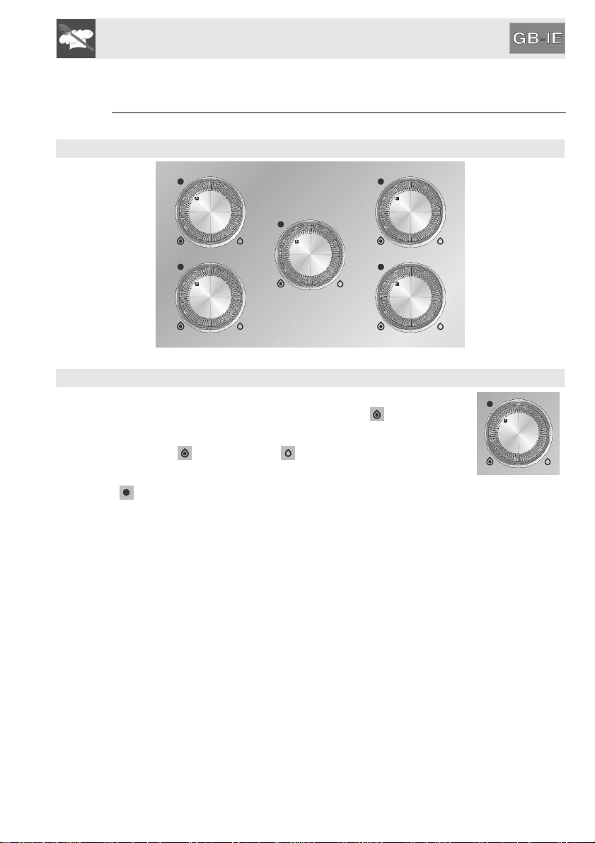
4.1 Control zone
All the hob controls are grouped together at the centre front.
CONTROL ZONE
KNOB DESCRIPTION
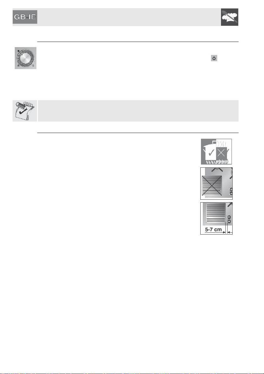
To light the flame, press the knob and, at the same time, turn it
anticlockwise to the maximum flame symbol .
To adjust the flame, turn the knob to the zone between the
maximum and minimum settings.
To turn off the burner, turn the knob to the zero position to the
symbol.
9
Instructions
for the user
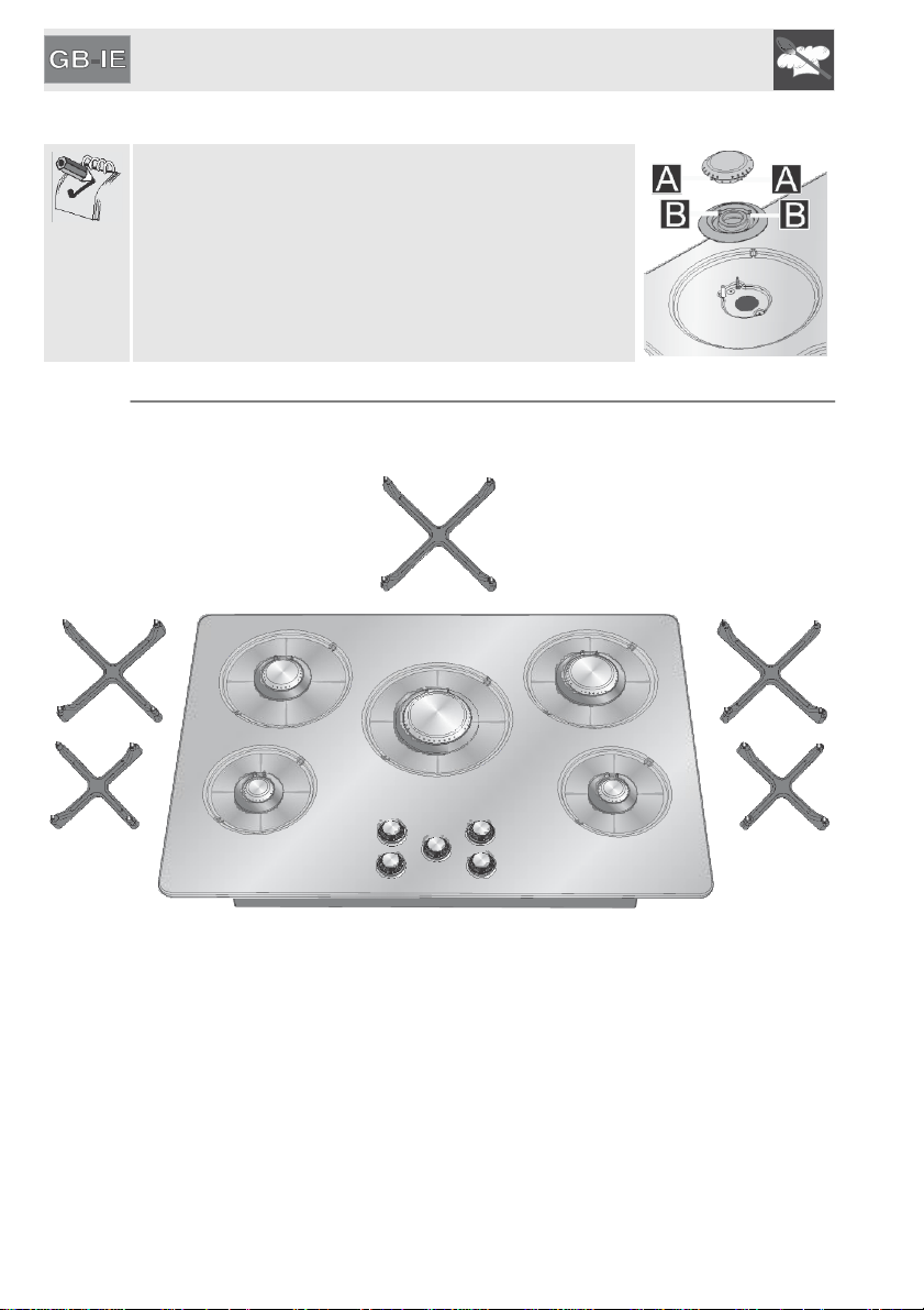
5. USING THE HOB
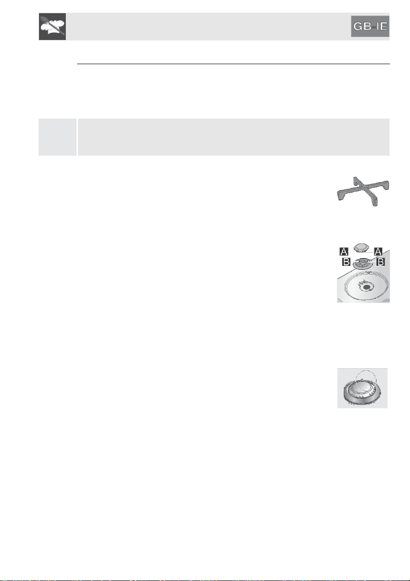
Make sure that the burners, flame-spreader crowns and
racks are fitted correctly.
The notches A of the flame-spreader crowns must
be inserted into the housings B of the burner. The
igniter and thermocouple on the hob should fit into the
2 holes on the burner.
5.1 Positioning the racks
The racks are provided unassembled on the hob. To position each rack correctly
on its burner, follow the instructions below:
Each rack must be positioned on the corresponding burner in order to guarantee
proper operation. Be very careful to match the different central diameters of the
racks to the flame-spreader crowns.
10
Instructions
for the user
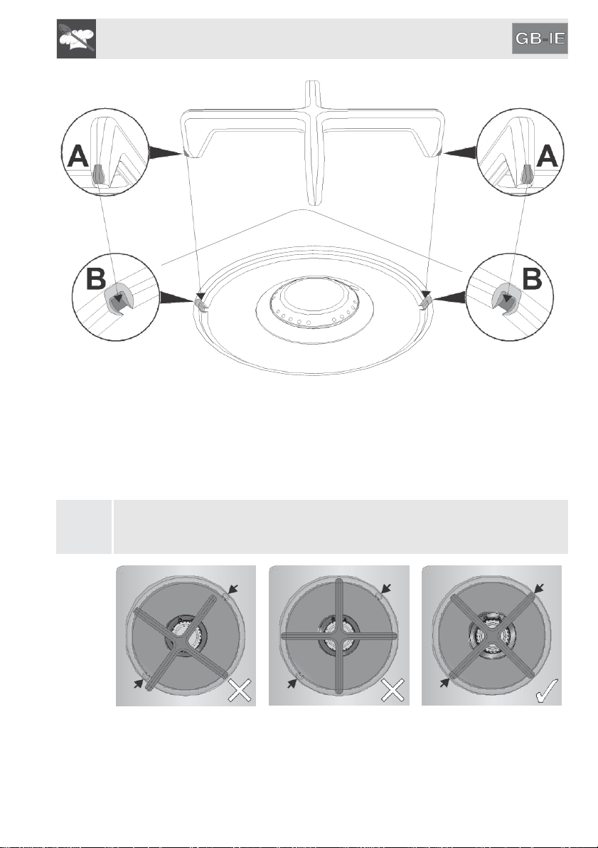
All the racks have two reference notches (A).
To position the racks correctly, align the reference notches (A) with the cavities
(B) on the hob.
After positioning, check that the rack feet are all resting on the same level.
Make sure that the racks are simply centred on their respective burners,
without forcing the burners to be raised or tilted. If they are, repeat
the positioning procedure.
INCORRECT INCORRECT CORRECT
11
Instructions
for the user
5.2 Lighting the burners using a safety device
The appliance is equipped with electronic ignition. Simply press the knob and
simultaneously turn it anticlockwise to the minimum flame symbol , until it
lights. Hold down the knob for about 2 seconds to keep the flame lit and
to
activate the safety device. The burner may go out when the knob is released. If
this happens, repeat the procedure, holding the knob down for longer.
If the burners should go out accidentally, after about 20 seconds a safety device
will be tripped, cutting off the gas supply, even if the gas tap is open.
5.3 Practical tips for using the burners
For better burner performance and minimum gas
consumption, pans with flat, even bases and with lids should
be used, and their size should be in proportion to the burner
(see “5.4 Pan diameters”).
During cooking, in order to avoid burns or damage to the hob
top, all pans or griddles must be positioned inside the outer
edge of the hob and at a minimum distance of 5-7 cm must be
maintained from the knobs.
If the burner flame accidentally goes out, turn off the control
knob and wait at least 1 minute before trying to re-light the
burner.
12
Instructions
for the user
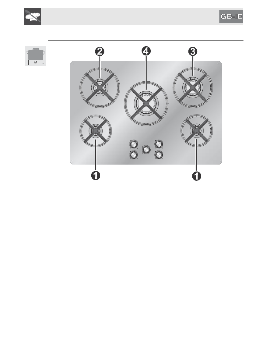
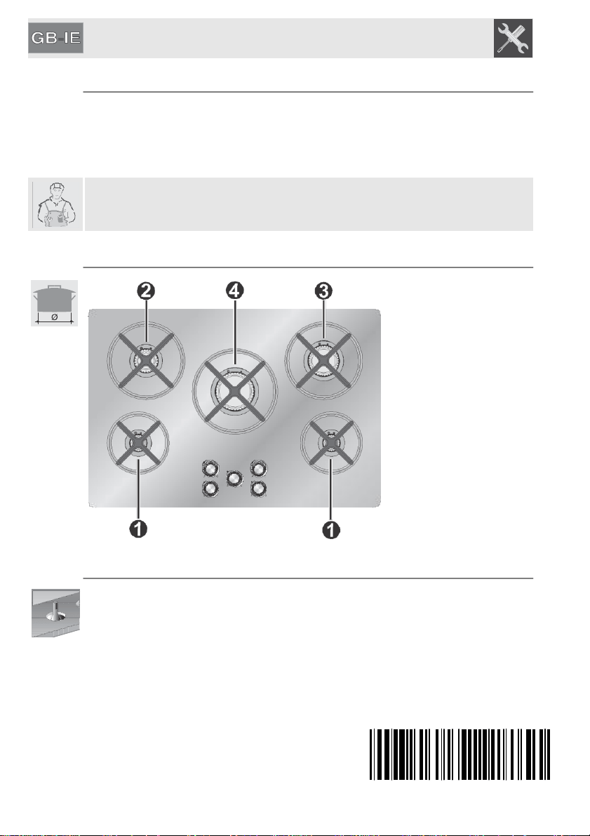
5.4 Pan diameters
BURNERS
1 Auxiliary
2. Semi-rapid
3 Medium Rapid
4 Large Rapid
min. and max. Ø (in cm)
7-18
10-24
18-24
20-26
13
Instructions
for the user
6. CLEANING AND MAINTENANCE
Before performing any operations requiring access to powered parts, disconnect
the appliance from the power supply.
6.1 Cleaning the hob
To keep the hob in good condition it should be cleaned regularly after use.
Let it cool first.
6.1.1 Ordinary daily cleaning
To clean and preserve the stainless steel surfaces, always use only
specific products that do not contain abrasives or chlorine-based acids.
How to use: pour the product onto a damp cloth and wipe the surface, rinse
thoroughly and dry with a soft cloth or chamois leather.
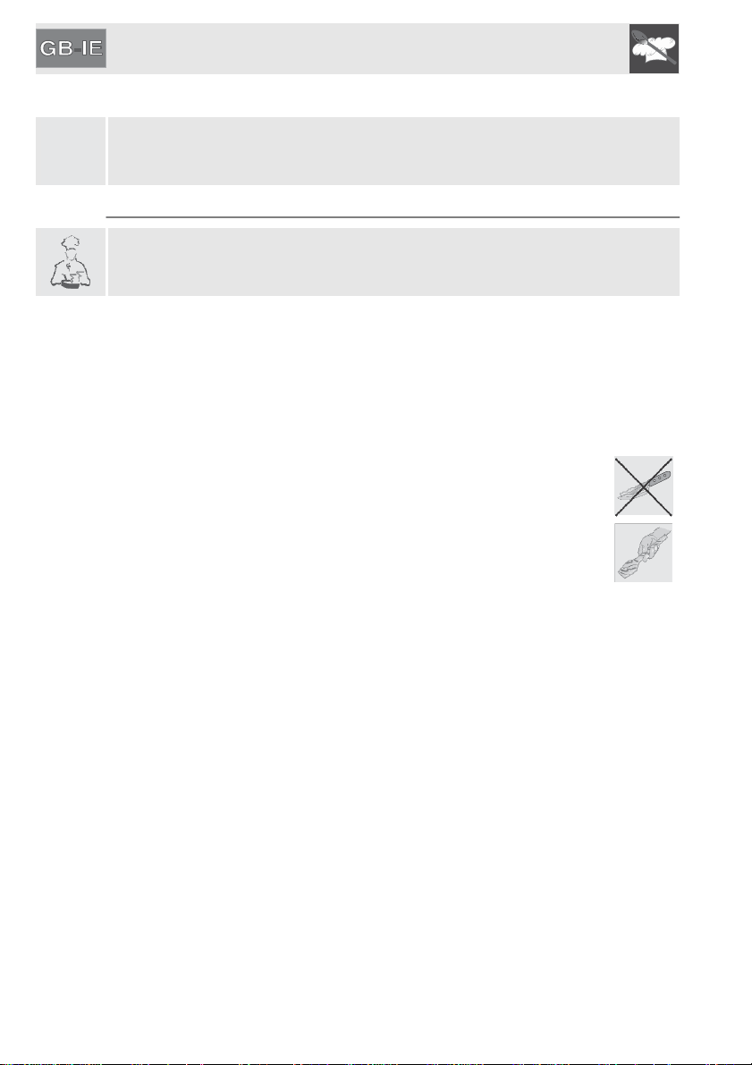
6.1.2 Food stains or residues
Do not use metallic sponges or sharp scrapers: they will damage the
surface.
Use ordinary non-abrasive products for steel, together with anti-
scratch sponges and wooden or plastic utensils if necessary.
Rinse thoroughly and dry with a soft cloth or chamois leather.
14
Instructions
for the user
6.2 Cleaning the components
6.2.1 Knobs
The knobs should be cleaned with a soft cloth dampened with lukewarm water,
then dried carefully. For easier cleaning they can be removed by pulling them
upwards.
Do not use aggressive products containing alcohol or products for cleaning steel
and glass when cleaning the knobs, as these products could cause permanent
damage.
6.2.2 Racks
Remove the racks and clean them with lukewarm water and non-
abrasive detergent, making sure to remove any
encrustations. Replace them on the cooking hob.
These components must not be washed in the dishwasher.
6.2.3 Flame-spreader crowns
The flame-spreader crowns are removable. Wash them with
lukewarm water and non-abrasive detergent, making sure to
remove any encrustations.
To remove burned on food residue, use Puliforno with a scourer
sponge.
For less stubborn residue and for polishing, use stainless
steel cream cleaner Crema Inox with a microfiber cloth.
After cleaning ensure they are perfectly dry and reposition them
correctly.
6.2.4 Igniters and thermocouples
For correct operation the igniters and thermocouples must always
be perfectly clean. Check them frequently and clean them with a
damp cloth if necessary. Remove any dry residues with a wooden
toothpick or a needle.
15
Instructions
for the installer
7. POSITIONING IN THE COUNTER TOP
The following operation requires building and/or carpentry work so must
be carried out by a competent tradesman.
Installation can be carried out on various materials such as masonry, metal,
solid wood or plastic laminated wood as long as they are heat resistant (T 90°C).
7.1 Fixing to the supporting structure
Create an opening in the top surface of the counter, keeping a minimum
distance of 50 mm from the rear edge.
This appliance can be mounted against walls higher than the work
surface in accordance with AS/NZS5601 so as to avoid damage from
overheating.
Make sure that there is a minimum distance of 600 mm between the highest
part of the highest burner and any combustible shelf or overhanging
combustible material that may be installed directly above it in accordance with
AS/NZS5601.
Do not use aggressive products containing alcohol or products for cleaning steel
and glass when cleaning the knobs, as these products could cause permanent
damage.
If installing over an empty kitchen unit with doors, a separation panel must be
placed under the hob. Keep a minimum distance of 10 mm between the bottom
of the appliance and the surface of the panel, which must be easily extractable
to allow sufficient access for any technical assistance.
16

Instructions for the installer
Carefully position the supplied insulating seal on the outer perimeter of the hole
made in the counter top as shown in the figures below, trying to make it stick on
the entire surface by applying light pressure on it with your hands. Depending
on the hob model being installed refer to the dimensions in the figure, bearing in
mind that for both models the long front side must brush against the hole. Fix
the hob to the unit using the appropriate brackets A supplied. Carefully trim the
surplus away from edge B beyond the seal. The dimensions given in
the following drawing refer from the hole to the inside of the seal.
The figure to the side shows the exact
holes to be used to correctly attach
the hob to the work surface with
brackets.
IMPORTANT: If installing the hob over an oven, ensure that the latter is
equipped with a cooling fan.
17
Instructions
for the installer
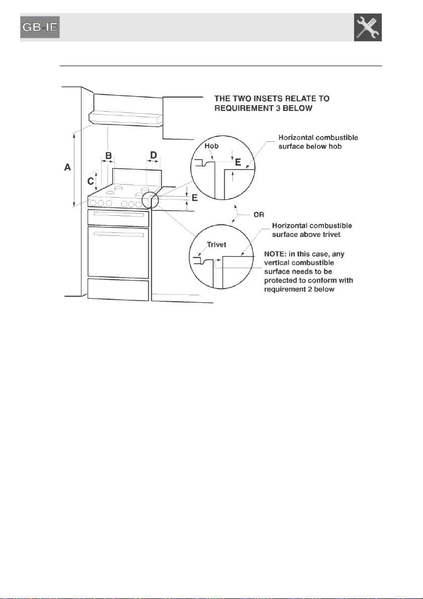
7.2 Clearances above and around domestic appliances
Extract from AS5601
REQUIREMENTS
1 Overhead clearances – (Measurement A)
Range hoods and exhaust fans shall be installed in accordance with
the manufacturer’s instructions. However, in no case shall the clearance
between the highest part of the highest burner of the cooking appliance and a
range hood be less than 600 mm
or
, f
or
an overhead exhaust fan, 750 mm.
Any other downward facing combustible surface less than 600 mm above the highest
part of the hob shall be protected for the
full
width
and depth of the cooking surface
area in accordance with Clause 5.12.1.2. However, in no case shall this clearance to
any surface be less than 450 mm.
2 Side clearances – (Measurements B & C)
Where B, measured from the periphery of the nearest burner to any vertical
combustible surface, is less than 200 mm, the surface shall be protected in
accordance with Clause 5.12.1.2 to a height C of not less than 150 mm above the
hob for the full dimension (width or depth) of the cooking surface area. Where the
cooking appliance is fitted with a ‘splashback’, protection of the rear wall is
not required.
18
Instructions for the installer
3 Additional requirements for Freestanding and Elevated Cooking
Appliaces – (Measurements D & E)
Where D, the distance from the periphery of the nearest burner to a
horizontal combustible surface is less than 200 mm, then E shall be 10 mm or
more, or the horizontal surface shall be above the trivet. See insets above.
NOTES
1 Requirement 3 does not apply to a freestanding or elevated
cooking
appliance which
is designed to prevent flames or the cooking vessels from extending beyond
the periphery of the appliance.
2 The ‘cooking surface area’ is defined as that part of the appliance
3 where cooking normally takes place and does not include
those
parts
of the appliance
containing control knobs.
4 For definition of hob, see Clause 1.4.64.
5 For definition of trivet, see Clause 1.4.109.
6 Consideration is to be given to window treatments when located near
cooking appliances. See Clause 5.3.4.
7.3 Combustion gas discharge
Combustion gases may be discharged by means of hoods connected to a flue
with reliable natural draught, or a fan extraction system. An effective extraction
system requires careful design by an authorised specialist, and must comply
with the regulation distances and positions. After installation, the engineer must
issue a certificate of compliance.
19
Instructions
for the installer
8. ELECTRICAL CONNECTION
Make sure that the voltage and capacity of the power supply line conform to the
data shown on the plate located under the casing. Do not remove this plate
for any reason.
The plug at the end of the supply cable and the wall socket must be of the same
type and must conform to the applicable legislation on electrical
installations. Make sure that the supply line is suitably earthed.
Pass the power supply cable through the back of the unit, taking care that
it does not touch the bottom casing of the hob or the oven (if any)
installed underneath it.
Fit the power supply line with an omnipolar circuit breaker with a contact
opening gap equal to or greater than 3 mm in an easily accessible position close
to the appliance.
Avoid use of adapters and shunts.
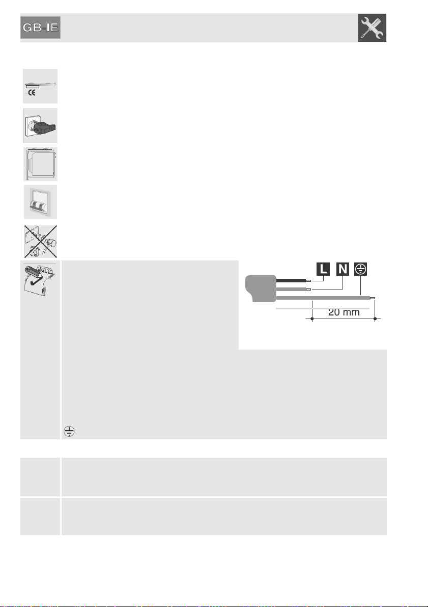
If the power cable is replaced, the
cross- section of wires in the new cable
must be
no less than 0.75 mm
2
(3 x 0.75 cable),
remembering that the end for connection to
the appliance must have an earth wire
(yellow/green) which is at least 20 mm
longer.
Only use a H05V2V2-F or similar cable resistant to the maximum temperature of
90°C. Its replacement must be carried out be a specialised technician who must
carry out the connection to the power grid following the diagram below.
L = brown
N = blue
= yellow/green
The power supply cable must be replaced by an authorised service centre to
prevent any risks.
The manufacturer declines all responsibility for damage to persons or
things
caused by non-observance of the above prescriptions or by interference
with any part of the appliance.
20
Instructions for the installer
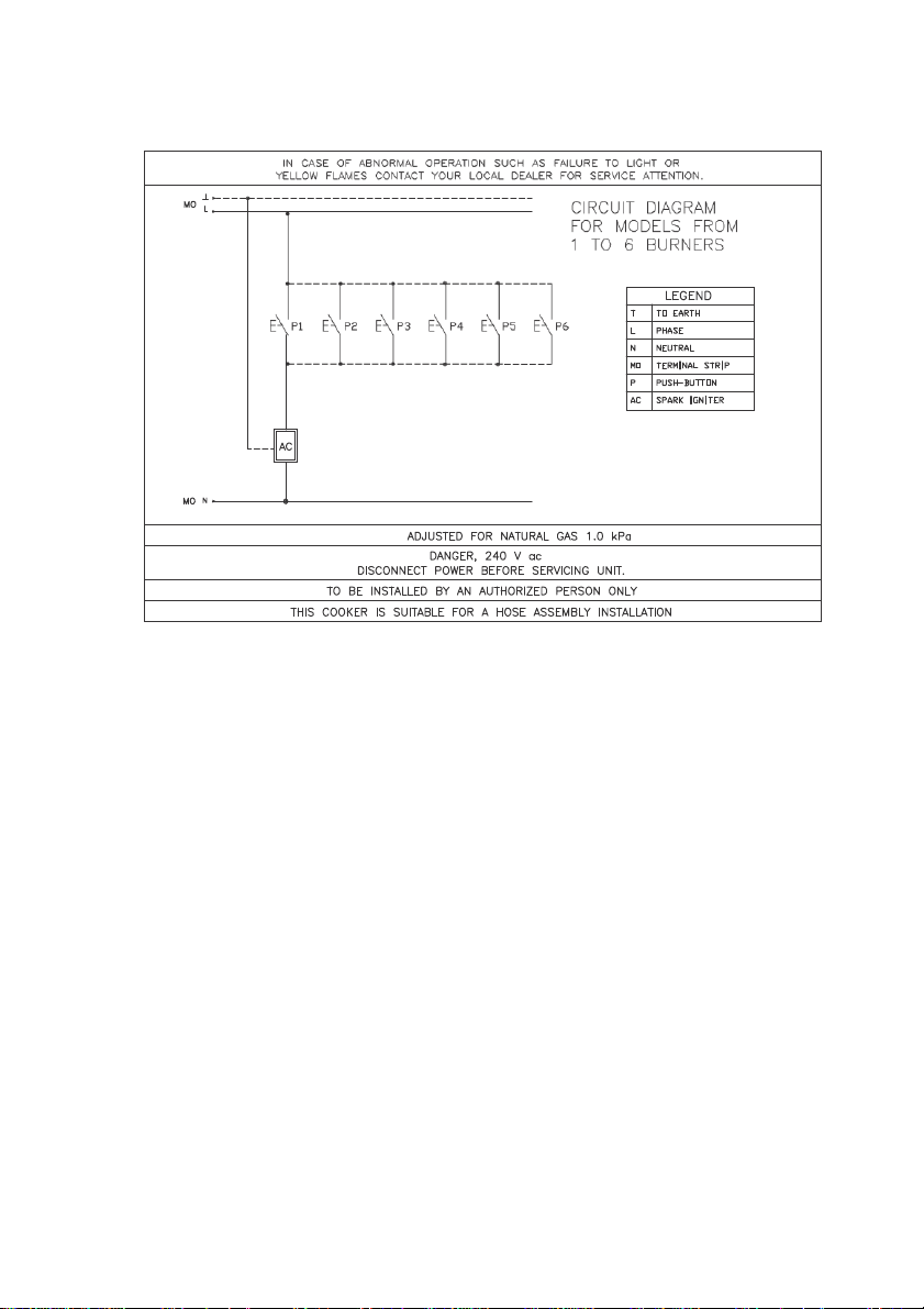
9. GAS CONNECTION
9.1 Gas connection
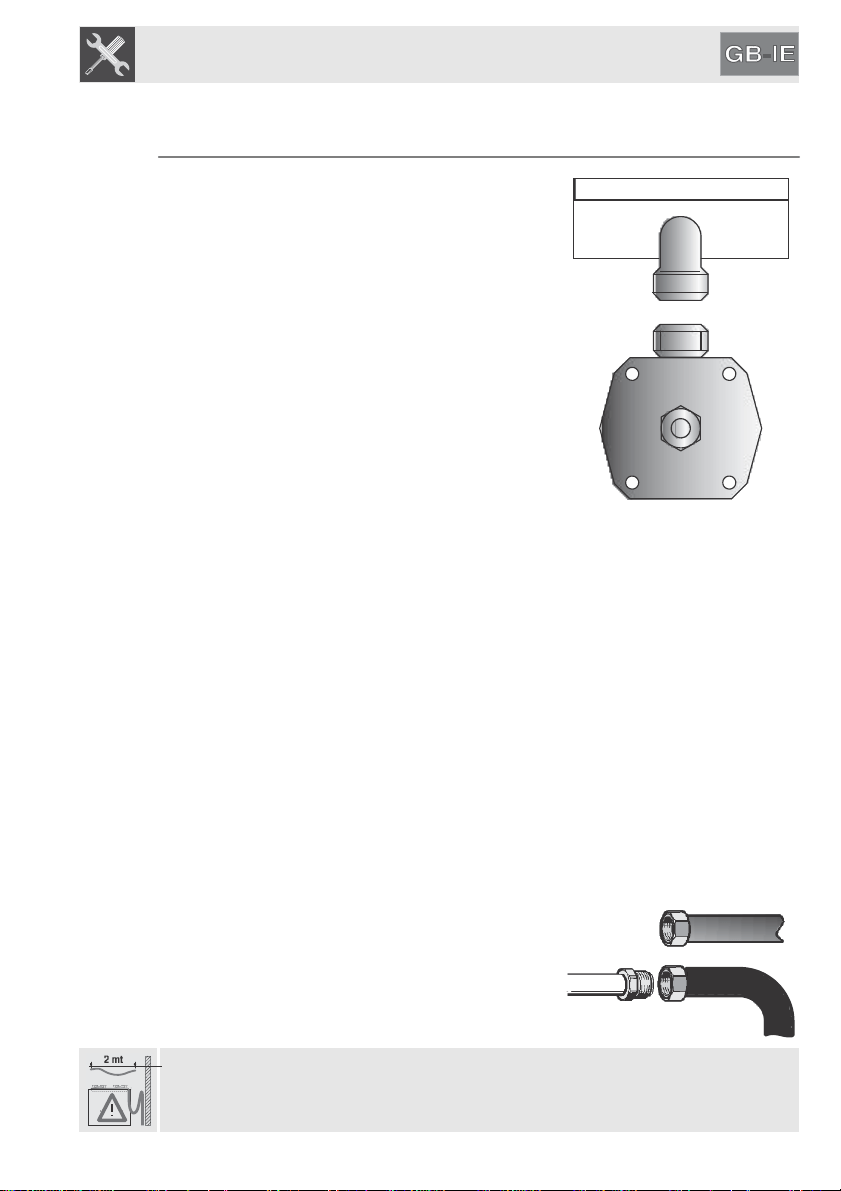
This appliance is suitable for installation with
Natural Gas or ULPG (propane/butane). Refer to
page 25 for the relevant burner pressure and
appropriate injector sizes. When the appliance is
to be connected to Natural Gas then the pressure
regulator supplied must be fitted to the gas inlet.
A test point (for checking the gas pressure) is
supplied either with the regulator or as a separate
fitting in the case of ULPG (propane) appliances.
Connection of the appliance to the gas
supply must be in accordance with the
requirements of AS/NZS5601. A ½” BSP
connector at the inlet is recommended and
the gas supply line to the appliance must be
of adequate length to allow sufficient
withdrawal of appliance for service or
disconnection and be:
1. annealed copper pipe or;
2. flexible hose according to AS/NZ1869 & be at least Class “B”, 10
mm diameter.
The appliance must be installed with provision to allow the gas to be turned off
and disconnected for servicing and removal of the appliance as required from
the gas supply. Before the appliance is operated make certain all relevant parts
are placed in the correct position.
On completion of the installation, the installer MUST check for gas leaks and
test each burner individually for the correct flame. Once all burners have been
tested individually, turn all burners on together.
Warranty service calls do not cover these adjustments!
To check the operating pressure of the appliance it is recommended at least 2
large size burners are used. Ensure appliance is secured to wall when
installation is completed.
N.G. The regulator supplied must be fitted to the ½ BSP thread at the rear of the
appliance. An approved manual shut-off valve must be installed. The
N.G. regulator must be checked and adjusted to 1.0kPa after installation.
U.L.P.G. Can be connected to the inlet fitting
directly. The pressure must be checked to ensure
it is operating at 2.75kPa. A separate test
point fitting must be installed between the piping
& the appliance for the pressure to be
checked to ensure it is operating at 2.75kPa.
Installation with flexible hose must be carried out so that the length of the piping
does not exceed 1.2 metres when fully extended; make sure that the hoses do
not come into contact with moving parts and that they are not crushed in any
way.
21
Instructions
for the installer
9.2 Connection to liquid gas
Use a pressure regulator and make the connection on the gas cylinder following
the guidelines set out in the regulations in force.
Make sure that the supply pressure complies with the values indicated in the
paragraph “10.3 Burner and nozzle characteristics tables”.
9.3 Room ventilation
The room containing the appliance should have a permanent
air
supply in
accordance with the Standards regulations
AS/NZS5601.
9.4 Extraction of the combustion products
The combustion products may be extracted by means of hoods connected to a
natural draught chimney whose efficiency is certain or via forced extraction. An
efficient extraction system requires precision planning by a specialist qualified in
this area and must comply with the positions and distances indicated by
the regulations. When the job is complete, the installer must issue a
certificate of conformity.
22
Instructions for the installer
10. ADAPTATION TO DIFFERENT TYPES OF GAS
Before carrying out the following operations, disconnect the appliance from the
power supply.
The hob is preset for natural gas at a pressure of 1kpa. If other
types of gas are to be used, the nozzles must be replaced and the primary air
must be adjusted.
In order to replace the nozzles and adjust the burners, the hob top must
be removed as described below.
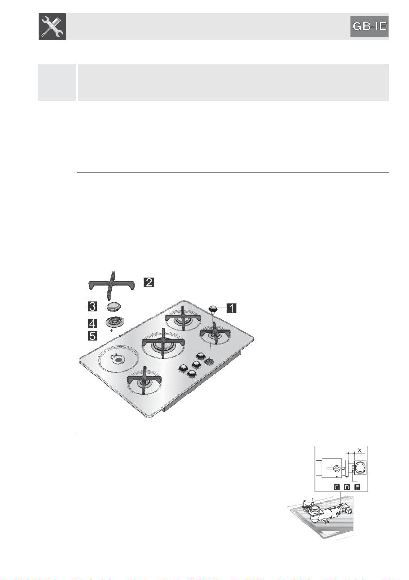
10.1 Removing the hob top
Remove all the burner components, following the numerical sequence in
the figures below:
• Take out all the knobs (1) by pulling them upwards;
• Remove the racks (2) by lifting them upwards;
• Lift all the burner components off the hob (3 - 4);
• Unscrew the screws (5) that secure the burner supports;
• Having removed all the components described above, lift the hob top
upwards to access the burners and gas taps.
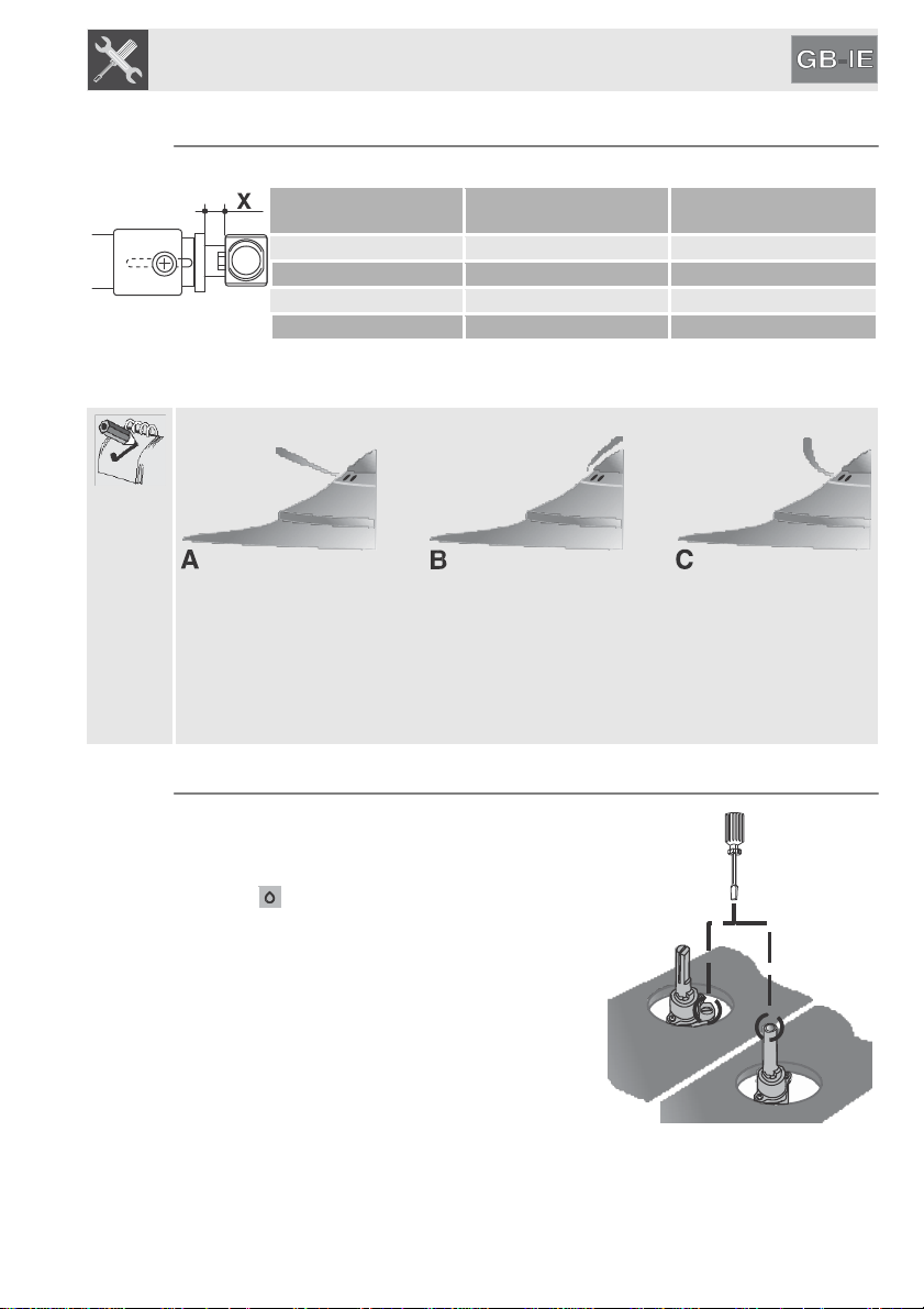
10.2 Replacement of the cooking hob nozzles
Unscrew screw C and push air regulator D as far as
it will go. Using a 7-mm wrench, remove nozzle
E and replace it with the appropriate nozzle,
following the instructions in the tables for the type of
gas to be used. The nozzle tightening torque must
be no more than 3 Nm. Adjust the air by sliding
regulator D until distance “X” is reached, as
indicated in the table in paragraph “10.4 Primary air
adjustment”.
Lock regulator D by tightening screw C.
23
Instructions
for the installer
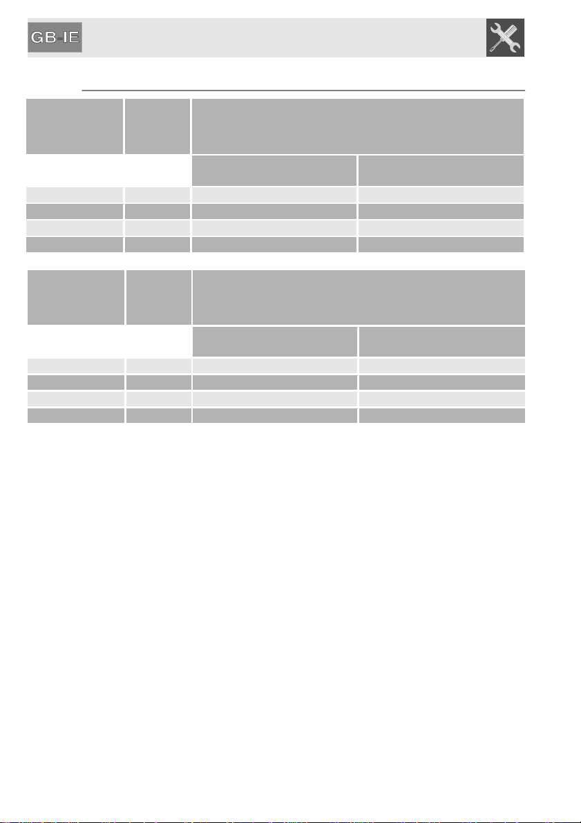
10.3 Burner and nozzle characteristics tables
Burner
ULPG -
2.75
kPa
Nominal
gas
consumption
(MJ/h)
Injector
(1/100
mm)
Auxiliary
4.1
54
Semi-Rapid
6.0
67
Medium-Rapid
9.5
85
Large-Rapid
11.5
95
Burner
Natural Gas -
1.0
kPa
Nominal
gas
consumption
(MJ/h)
Injector
(1/100
mm)
Auxiliary
4.7
98
Semi-Rapid
6.1
110
Medium-Rapid
9.0
135
Large-Rapid
11.5
160
24
Instructions for the installer
10.4 Primary air adjustment
Refers to distance “X” in mm.
BURNER
ULPG
2
.
75
kPa
Natural
Gas
1.0
kPa
Auxiliary
7
1
Semi-rapid
2
0.5
Medium Rapid
2
1
Large Rapid
10
1.5
To identify the burners on your hob, please refer to the illustrations in paragraph
“10.7 Arrangement of the burners on the hob”.
If having adjusted the air the flame appears as illustrated in the figure:
the following modifications must be made:
A: the flame is "noisy", unstable or "detaches" from the burner: the primary air is
too high.
B: The flame is opaque, dull or has yellow tips and "wraps around" the burner:
the primary air is too low.
C: The flame is blue, clear and stable, does not "detach" or "wrap around" the
burner: the air is adjusted correctly.
10.5 Adjusting the minimum for natural gas
Reposition the components on the burner and
slide the knobs onto the tap rods.
Light the burner and set it to the minimum
position .
Extract the knob again and turn the adjustment
screw inside or next to the tap rod (depending
on the model) until the correct minimum flame
is achieved.
Refit the knob and verify that the burner flame
is stable (when turning the knob rapidly from
the maximum to the minimum position the
flame must not go out).
25
Instructions
for the installer
10.6 Adjusting the minimum setting for LPG
To adjust the minimum setting with LPG, you must tighten the screw inside or
next to the tap rod (depending on the model) fully in a clockwise direction.
The diameters of the by-passes for the individual burners are given in the table
“10.3 Burner and nozzle characteristics tables”.
After adjustment with a gas other than the preset one, replace the label on the
casing of the appliance with the label corresponding to the new gas. The label is
inserted inside the pack together with the nozzles.
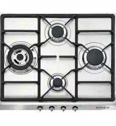
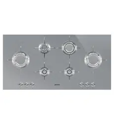
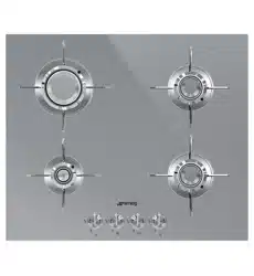
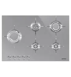
10.7 Arrangement of the burners on the hob
Type of burner
1 Auxiliary
2 Semi-rapid
3 Medium Rapid
4 Large Rapid
10.8 Lubrication of gas taps
Over time the gas taps may become difficult to turn and get blocked. Clean them
internally and replace the lubrication grease.
This procedure must be carried out by a specialised technician.
914774717/
A
26
I
The manufacturer reserves the right to make any changes deemed useful for improvement of his products without
prior notice. The illustrations and descriptions contained in this manual are therefore not binding and are merely
indicative.

Space for rating plate
914774717/
A