Loading ...
Loading ...
Loading ...
USER GUIDE
Control Operation - Service 4
u-line.com
SAFETY • INSTALLATI ON & INTEGRATI ON • OPERATI NG INSTRUCTIONS • MAINTENANCE • SERV I CE
14. VI EW ERROR LOG
A list of the errors in the order they occurred will
scroll once on the display. All errors are logged
in memory. Only door error is displayed on the
display and has an audible signal.
E0 : Door 1 (upper) open.
E1 : Thermistor 1 open.
E2 : Thermistor 2 open.
E3 : Thermistor 3 open.
E4 : Thermistor 4 open (Does not apply to this
model).
E5 : Thermistor 1 shorted.
E6 : Thermistor 2 shorted.
E7 : Thermistor 3 shorted.
E8 : Thermistor 4 shorted (Does not apply to this
model).
E9 : Door 2 (lower) open.
P1 : Pump Circuit open (Does not apply to this
model).
15. CLEAR ERROR LOG
To clear errors, press and hold
(5 seconds)
when CLR is flashing.
16. THERM I STOR — 1 DI FFERENTI AL
This number should not be adjusted.
17. EVAPORATOR FAN D ELAY I N M I N UTES —
ON
“Fan Delay On” is the amount of time in minutes
the fan will be delayed from starting from the
beginning of a cooling cycle. Adjustable 0- 99
minutes.
18. EVAPORATOR FAN D ELAY I N M I N UTES —
OFF
“ Fan Delay Off ” is t he am ount of t im e in m inut es
the fan will continue to run at the end of a
cooling cycle. Adjustable 0- 99 minutes.
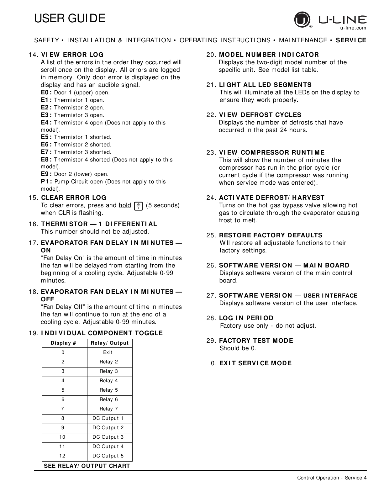
19. I NDI VI DUAL COMPON EN T TOGGLE
20. MODEL N UMBER I N D I CATOR
Displays the two-digit model number of the
specific unit. See model list table.
21. LI GHT ALL LED SEGMEN TS
This will illuminate all the LEDs on the display to
ensure they work properly.
22. VI EW DEFROST CYCLES
Displays the number of defrosts that have
occurred in the past 24 hours.
23. VI EW COMPRESSOR RUN TI ME
This will show the number of minutes the
compressor has run in the prior cycle (or
current cycle if the compressor was running
when service mode was entered).
24. ACTI VATE D EFROST/ HARVEST
Turns on the hot gas bypass valve allowing hot
gas to circulate through the evaporator causing
frost to melt.
25. RESTORE FACTORY DEFAULTS
Will restore all adjustable functions to their
factory settings.
26. SOFTW ARE VERSI ON — M AI N BOARD
Displays software version of the main cont rol
board.
27. SOFTW ARE VERSI ON —
USER I NTERFACE
Displays software version of the user interface.
28. LO G I N PERI OD
Factory use only - do not adjust.
29. FACTORY TEST M ODE
Should be 0.
0. EXI T SERVI CE M OD E
D isplay # Relay/ Out put
0 Exit
2 Relay 2
3 Relay 3
4 Relay 4
5 Relay 5
6 Relay 6
7 Relay 7
8 DC Output 1
9 DC Output 2
10 DC Output 3
11 DC Output 4
12 DC Output 5
SEE RELAY/ OUTPUT CH ART
Loading ...
Loading ...
Loading ...