nl iiiii ilnll II I I IIIIII
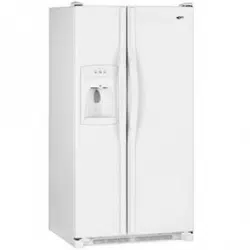
_ana_ 24" Deep
Side-By-Side Built-In Refrigerator
Use & Care Manual
_.,aea 20
i,l,i , ,HI '"n" ,,,,,,,,,,,,,,,i

Welcome to
the Amana Family
Your purchase of an Amana refrig-
erator/freezer--a household
appliance known for its quality and
reliability--is sincerely appreciated by
Amana Refrigeration, Inc. Your total
satisfaction with this new product is
extremely important to us, and this
Use and Care Manual will aid you in
understanding the operation of your
new appliance.
Each product is thoroughly tested
and checked at the factory. Once in
your home, you may want to make a
few simple adjustments of control set-
tings, etc. to tailor your new unit to
your own individual requirements.
These adjustments are easily made
following the instructions in this
manual.
Should your new unit ever require
service, certain product information
will aid in obtaining service faster! For
your convenience and protection,
please record this information in the
box at right and retain this booklet for
future reference.
The Registration Card in the packet
with the manual should be filled out
and returned to Amana Refrigera-
tion, Inc.
Record in the space below
the information found on the
nameplate of your refriger-
ator. The nameplate is
located on the ceiling of the
refrigerator section. Also,
please retain a copy of your
sales receipt for future
reference should warranty
service be needed.
Serial No,
Model No...........................
Manufacturing No
Date of Purchase
Selling Dealer
, WARNING
Electrical Grounding Instructions--This appliance is equipped with a three-prong (grounding)
plug for your protection against possible shock hazards. Where a two-prong wall receptacle is
encountered, it is the personal responsibility end obligation of the customer to contact a
qualified electrician and have it replaced with a properly grounded three-prong wall receptacle in
accordance with the National Electrical Code (see figure.)
Unit is designed to operate on a separate 103 to 126 V.A.C., 15 amp., 60 cycle line.
DO NOT UNDER ANY CIRCUMSTANCES CUT OR REMOVE THE ROUND
GROUNDING PRONG FROM THE PLUG. "['HE UNIT MUST BE GROUNDED AT
ALL TIMES. DO NOT REMOVE WARNING TAG FROM THE SERVICE CORD.
_LECTRIC.AL PLUG WITH GROUNDING PRONG ELECTRICAL REC_ACLE WITH
WARNING o.oo.o,.o.ooo..cL.
DO NOT USE A TWO-PRONG ADAPTER, !1_'; J'
DO NOT USE AN EXTENSION CORD, "OUNDGROU"D="GP_ONG
2
Contents Page
E_ectricaJWarning ................ 2
Unpacking ...................... 3
Door Handle Removal ............. 3
Door Removal ................... 3
Placement, Door Alignment
and Leveling .................... 5
Door Panel and Dispenser
Trim InstallationInstructions ......... 6
The Ice 'N Water Dispenser ......... 8
General Features ................ 11
Setting the Controls .............. 12
Refrigerator Features ............. 13
Contents Page
Freezer Features .............. 15
Other Features ................. 16
Save Energy ................... 17
Care and Cleaning .............. 18
Non-Use Periods ................ 20
Sounds ....................... 21
Before Calling For Service ......... 22
Amana Asure .................. 23
Amana Toll-Free ................ 23
Unpacking, Door Handle and Door Removal
CAUTION:
To Avoid The Risk Of Personal
Injury use caution in
unpacking, handling, removing,
instalFing and cleaning atl parts
of product which may have
sharp edges.
,CAUTiON:
To Avoid The Risk Of Personal
Injury wear protective hand
covering.
Remove a}l tape and packing mate-
rial. To remove tape residue, touch
a portion of the tape to the residue
and lift it off, If adhesive residue still
remains, try cleaning the sticky area
with a clean cloth soaked in mild
dish washing soap, Wipe area
clean, tf the wood base is still
attached, have someone help you
tilt the unit onto its back, placing a
sturdy support underneath. Remove
the mounting bolts from the base
and discard bolts and wood base.
IMPORTANT! DOnot leave the cabi-
net on it's back longer than it takes
to remove the wooden base and do
not connect the power cord until
after al! the inside packing has
been removed and the cabinet has
been leveled for proper operation.
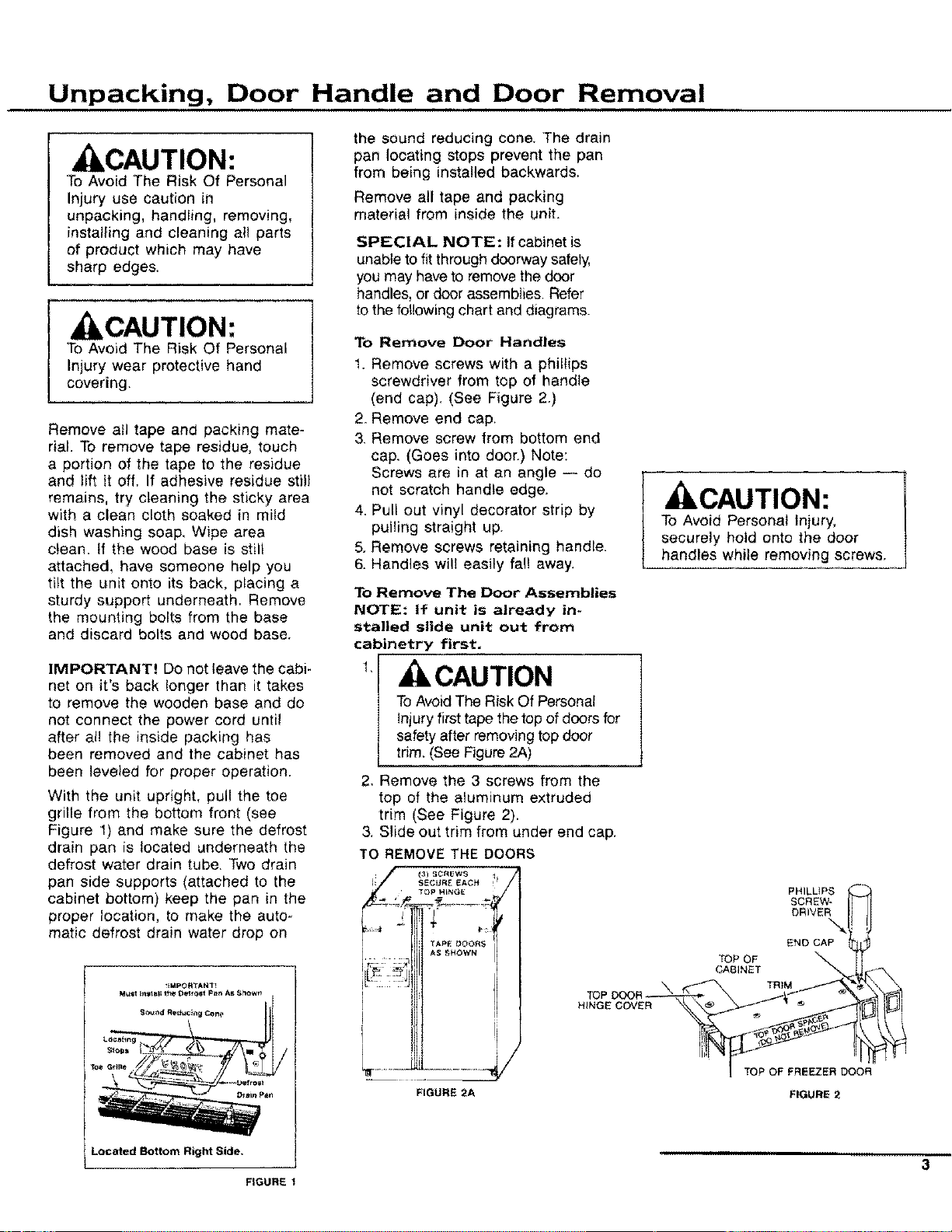
With the unit upright, pull the toe
grille from the bottom front (see
Figure 1) and make sure the defrost
drain pan is located underneath the
defrost water drain tube. Two drain
pan side supports (attached to the
cabinet bottom) keep the pan in the
proper location, to make the auto-
matic defrost drain water drop on
the sound reducing cone. The drain
pan locating stops prevent the pan
from being installed backwards,
Remove all tape and packing
material from inside the unit.
SPECIAL NOTE: If cabinet is
unable to fit through doorway safely,
you may have to remove the door
handles, or door assemblies. Refer
to the following chart and diagrams.
To Remove Door Handles
1. Remove screws with a phillips
screwdriver from top of handle
(end cap). (See Figure 2.)
2. Remove end cap,
3. Remove screw from bottom end
cap. (Goes into doer.) Note:
Screws are in at an angle -- do
not scratch handle edge.
4. Pull out vinyl decorator strip by
pulling straight up.
5. Remove screws retaining handle.
6. Handles will easily fall away,
To Remove The Door Assemblies
NOTE: If unit is already in-
stalled slide unit out from
cabinetry first.
t, CAUTION
To Avoid The Risk Of Personal
injuryfirst tape the top of doors for
safety after removing top door
trim. (See Figure 2A)
2, Remove the 3 screws from the
top of the aluminum extruded
trim (See Figure 2).
3. Slide out trim from under end cap.
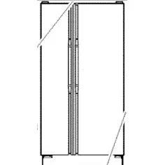
TO REMOVE THE DOORS
.................,y
FIGURE 2A
CAUTION:
To Avoid Personal Injury,
securely hold onto the door
handles while removing screws.
PHILLIPS
SCREW-
DRIVER
END CAP
TOP OF
CABINET
TRiM
TOP OF FREEZER DOOR
FIGURE 2
Located Bottom Right Side, , ,,n_,,,,,,
-- 3
FIGURE 1
Door Removal
,,,,,
4
, ILCAUTION:
To Avoid The Risk Of Personal
Injury Or Property Damage
have two people remove the
door, One to hold the door and
one to remove the safety tape,
and help with the tools,
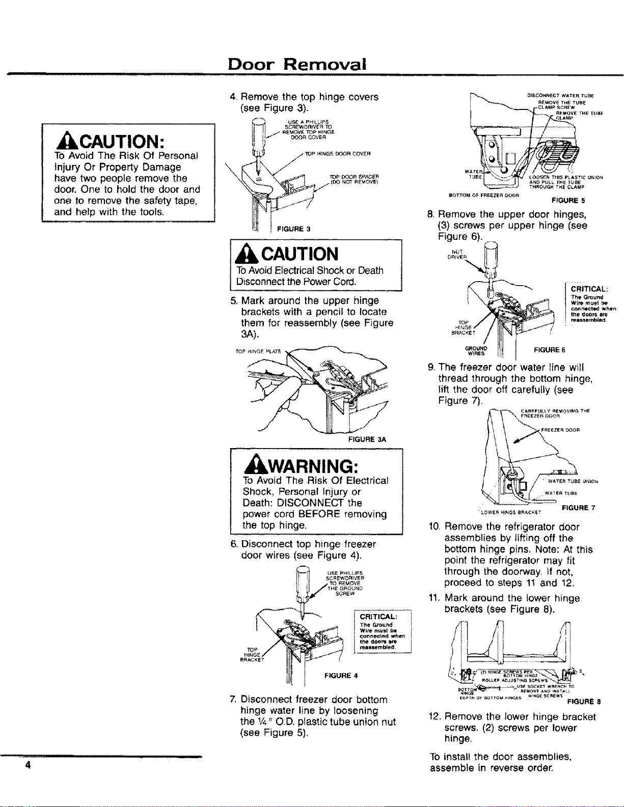
4, Remove the top hinge covers
(see Figure 3).
FIGURE 3
[ CAUTION
ToAvoid Electrical Shock or Death
Disconnect the Power Cord,
5. Mark around the upper hinge
brackets with a pencil to locate
them for reassembly (see Figure
3A).
TOP HINGE PLATE
FIGURE 3A
J WARNING:
To Avoid The Risk Of Electrical
Shock, Personal Injury or
Death: DISCONNECT the
power cord BEFORE removing
the top hinge,
6, Disconnect top hinge freezer
door wires (see Figure 4),
7. Disconnect freezer door bottom
hinge water line by loosening
the 1/4"O.D. plastic tube union nut
(see Figure 5).
O}SCONNECT WATER TU_
R_:MOV_ THE TUB_
CLAMp SCR_'W
REMOVE TH_ TUB_
__LAMP
WArE !
1UBE LOOSEN THIS p_.AgTIC UNION
A_IO pt_LL THE TUBE
P
_TTO_I OF FR_EZE_I OOOR
FIGURE 5
8. Remove the upper door hinges,
(3) screws per upper hinge (see
Figure 6).
r_UT
DRIVER
H_NG_
B_GKE _
GROUND
WIRES
k
CRITICAL:
I FIGURE 6
g. The freezer door water line will
thread through the bottom hinge,
lift the door off carefully (see
Figure 7).
• WATE_ I YklllE U_4;ON
2/:2
LOWE_H_E S_C_ET FIGURE 7
10.
Remove the refrigerator door
assemblies by lifting off the
bottom hinge pins. Note: At this
point the refrigerator may fit
through the doorway. If not,
proceed to steps 11 and 12.
11. Mark around the lower hinge
brackets (see Figure 8),
FIGURE 8
12_Remove the lower hinge bracket
screws. (2) screws per lower
hinge,
To install the door assemblies,
assemble in reverse order.
Placement, Door Alignment and Leveling
Placement
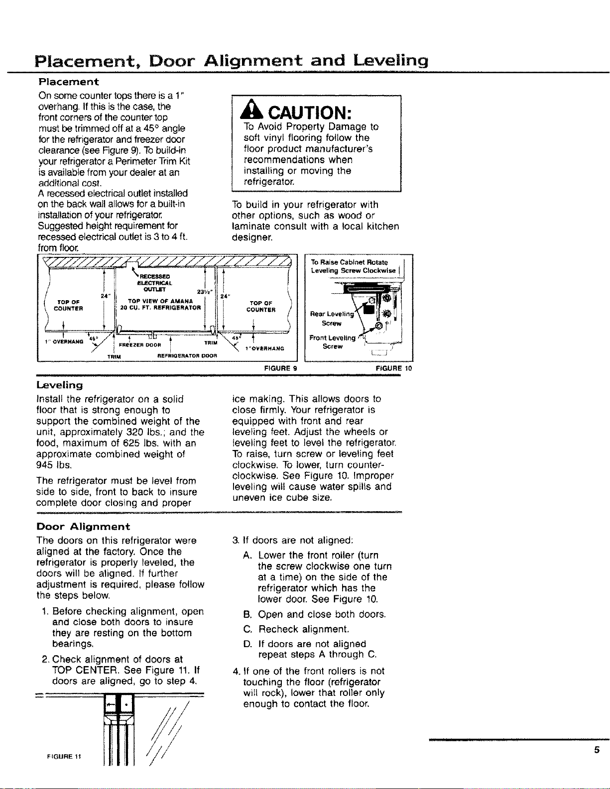
On some counter tops there is a 1"
overhang. If this is the case, the
front corners of the counter top
must be trimmed off at a 45° angle
for the refrigerator and freezer door
clearance (see Figure 9), Tobuild-in
your refrigerator a Perimeter Trim Kit
is available from your dealer at an
additional cost.
A recessed electrical outlet installed
CAUTION:
To Avoid Property Damage to
soft vinyl flooring follow the
floor product manufacturer's
recommendations when
installing or moving the
refrigerator.
on the back wallallows for a built-in
installation of your refrigerator,
Suggested height requirement for
recessed electrical outlet is 3 to 4 ft.
from floor.
24 _
!" OVERHANG_
TRIM
ELE(_fR_L 1
231/t.
TOP VIEW OF AMANA
20 CU* FT, REFRIGERATOR
.........½
FREEZER DOOR / TRIM
i
REFRIGERATOR DOOR
i
Leveling
Install the refrigerator on a solid
floor that is strong enough to
support the combined weight of the
unit, approximately 320 Ibs,; and the
food, maximum of 625 Ibs, with an
approximate combined weight of
945 Ibs.
To build in your refrigerator with
other options, such as wood or
laminate consult with a local kitchen
designer.
24" 1
TOP OF
COUNTER
_L _..J
\ 1"O'VE_HANG
FIGURE
The refrigerator must be level from
side to side, front to back to insure
complete door closing and proper
___lI_ _ ,,,,,.,_
Rear Leveling i
Screw _
FIGURE 10
ice making. This allows doors to
close firmly, Your refrigerator is
equipped with front and rear
leveling feet. Adjust the wheels or
leveling feet to level the refrigerator.
To raise, turn screw or leveling feet
clockwise, To lower, turn counter-
clockwise. See Figure 10. Improper
leveling wilt cause water spills and
uneven ice cube size,
Door Alignment
The doors on this refrigerator were
aligned at the factory. Once the
refrigerator is properly leveled, the
doors will be aligned. If further
adjustment is required, please follow
the steps below.
1. Before checking alignment, open
and close both doors to insure
they are resting on the bottom
bearings,
2. Check alignment of doors at
TOP CENTER. See Figure 11, If
doors are aligned, go to step 4,
/
3, If doors are not aligned:
A_
Lower the front roller (turn
the screw clockwise one turn
at a time) on the side of the
refrigerator which has the
lower door. See Figure 10.
B, Open and close both doors.
C. Recheck alignment.
D. If doors are not aligned
repeat steps A through C.
4. If one of the front rollers is not
touching the floor (refrigerator
will rock), lower that roller only
enough to contact the floor.
5
FIGURE 11
Door Panel and
Dispenser Trim Installation Instructions
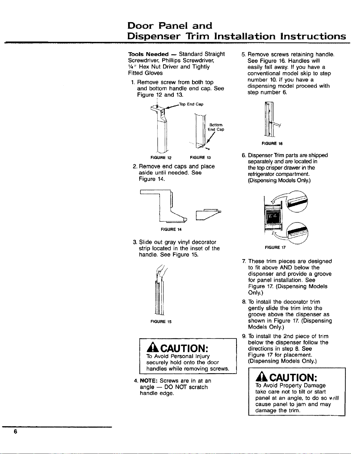
Tools Needed -- Standard Straight
Screwdriver, Phillips Screwdriver,
1/4" Hex Nut Driver and Tightly
Fitted Gloves
1. Remove screw from both top
and bottom handle end cap. See
Figure 12 and 13.
i
Bottom
End Cap
FIGURE 12 FIGURE 13
2. Remove end caps and place
aside until needed. See
Figure 14.
FIGURE 14
5, Remove screws retaining handle,
See Figure 16, Handles will
easily fall away. If you have a
conventional model skip to step
number 10, If you have a
dispensing model proceed with
step number 6.
FIGURE 16
6. DispenserTrim parts are shipped
separately and are located in
the top crisper drawer in the
refrigerator compartment.
(Dispensing Modets Oniy.)
3. Slide out gray vinyl decorator
strip located in the inset of the
handle. See Figure 15.
FIGURE 15
, CAUTION:
To Avoid Personal Injury
securely hold onto the door
handles while removing screws.
4. NOTE: Screws are in at an
angle -- DO NOT scratch
handle edge.
.
g.
FIGURE 17
These trim pieces are designed
to fit above AND below the
dispenser and provide a groove
for panel installation. See
Figure 17.(Dispensing Models
Only.)
To install the decorator trim
gently slide the trim into the
groove above the dispenser as
shown in Figure 17. (Dispensing
Models Only.)
To install the 2nd piece of trim
below the dispenser follow the
directions in step 8. See
Figure 17 for placement.
(Dispensing Models Only.)
CAUTION:
To Avoid Property Damage
take care not to tilt or start
panel at an angle, to do so _yill
cause panel to jam and may
damage the trim.
m
6
Door Panel and
Dispenser Trim Installation Instruction (cont.)
10. Gently insert the decorator panel
into grooves and slide EVENLY
until the panel is securely in
place.
11. To replace handles reverse the
procedures above. Numbers 1
through 5.
Decorator Doors
Tools Needed -- Standard Straight
Screwdriver and Tightly Fitted Gloves
The door fronts are to be decorated
with panels to accent your kitchen
decor. Models are equipped with
metal door edge trim kits required
to do this.
The basic %" trim kit is attached to
the door edges and hold lt4"-thick
panels. A _'16"filler such as card-
board is requiredfor 1h6"panel. Ask
your Amana dealer about panel
availability, or you may supply your
own panels.
For your convenience the panel
dimensions are listed below:
SBI20
Freezer Door 14"x 631A6"
5 s/
Refrigerator Door 19_ x 631/_s"
SBD20
Upper Freezer Door 14"x 18¾"
Lower Freezer Door 14"x 3111/ts"
Refrigerator Door 19%"x 631A6"
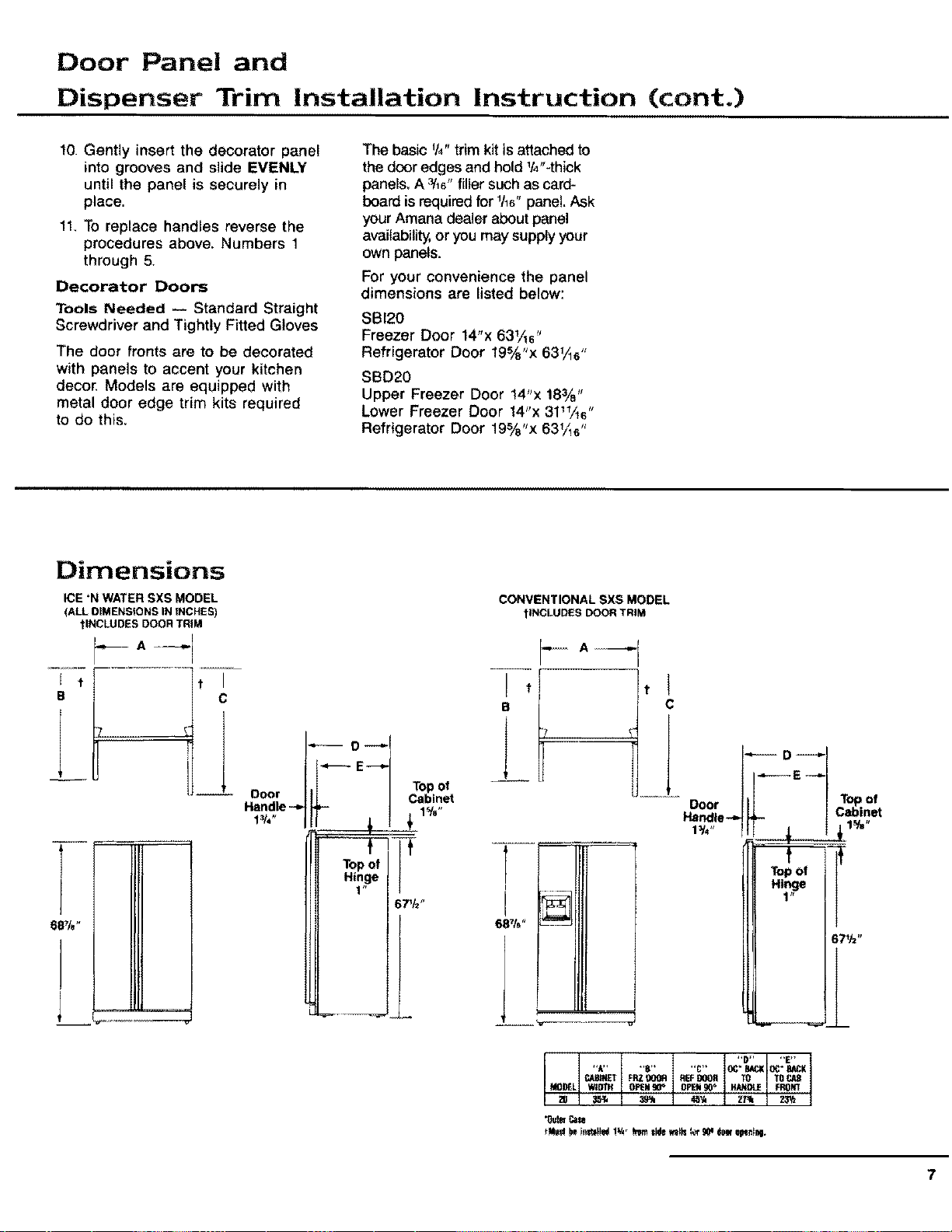
Dimensions
ICE 'N WATER SXS MODEL
(ALL OIMENSIONS IN tNCHES)
?INCLUDES DOOR TRIM
J t t
e C
I
O----I
O r hi Topoi
Do | 1[ I Cabinet
Handle _ pp- I 1%"
CONVENTIONAL SXS MODEL
1INCLUDESDOORTRIM
B C
]
T-
I
"D.... E"
"A.... B.... C" OC*BAC;KOC"BACK
CAPANETFP.ZgOOR REFDOOR TO TO
35#4 3_ 4_ Z/_ 23W
MO_L WIDTH OPEN_ OPEN90_ HANDLE FK4)N1
*Os'teCale
7
The Ice 'N Water Dispenser
8
Connect the Ice 'N Water
System To Cold Water
Supply,
Refer to the instructions on the
back of the cabinet.
, CAUTION
Toavoid cross threading and water
leaks, turn the water tube fittings by
hand several times before tightening
with wrenches, DO NOT OVER-
TIGHTEN. Also be sure to double
check for water leaks after turning on
the water pressure to the refrigerato_
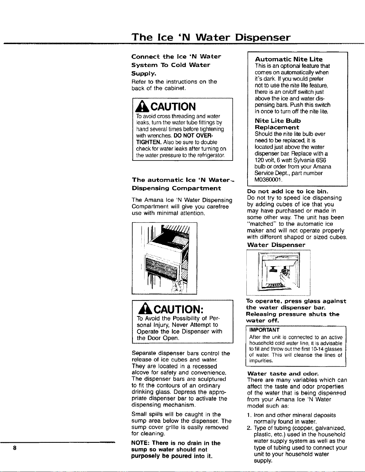
The automatic ice 'N Water,_
Dispensing Compartment
The Amana Ice 'N Water Dispensing
Compartment will give you carefree
use with minimal attention.
CAUTION:
To Avoid the Possibility of Per-
sonal Injury, Never Attempt to
Operate the Ice Dispenser with
the Door Open.
Separate dispenser bars control the
release of ice cubes and water.
They are located in a recessed
alcove for safety and convenience,
The dispenser bars are sculptured
to fit the contours of an ordinary
drinking glass. Depress the appro-
priate dispenser bar to activate the
dispensing mechanism.
Small spills will be caught in the
sump area below the dispenser. The
sump cover grille is easily removed
for cleaning.
NOTE: There is no drain in the
sump so water should not
purposely be poured into it,
Automatic Nite Lite
This isan optional feature that
comeson automaticallywhen
it's dark, Ifyou wouldprefer
not to use the nite litefeature,
there is an on/offswitch just
above the ice and waterdis-
pensing bars, Push this switch
in once to turn off the nite lite,
Nite Lite Bulb
Replacement
Should the nite lite bulb ever
need to be replaced, it is
located just above the water
dispenser bar. Replace with a
120 volt, 6 watt Sylvania 6S6
bulb or order from your Amana
Service Dept., part number
M0360001.
Do not add ice to ice bin.
Do not try to speed ice dispensing
by adding cubes of ice that you
may have purchased or made in
some other way. The unit has been
"matched" to the automatic ice
maker and will not operate properly
with different shaped or sized cubes.
Water Dispenser
To operate, press glass against
the water dispenser bar.
Releasing pressure shuts the
water off.
IMPORTANT
After the unit is connected to an active
household cold water line, it is advisable
to fill and throw out the first 10-14glasses
of water. This wilt cleanse the lines of
impurities,
Water taste and odor.
There are many variables which can
affect the taste and odor properties
of the water that is being dispensed
from your Amana Ice 'N Water
model such as:
1. Iron and other mineral deposits
normally found in water.
2. Type of tubing (copper, galvanized,
plastic, etc.) used in the household
water supply system as well as the
type of tubing used to connect your
unit to your household water
supply.
The Ice 'N Water Dispenser (cont.)
3. Is the water "fresh" or has it been
left standing unused in the storage
reservoir andtor water supply line
for any length of time?
To minimize taste and odor problems,
it is recommended that the following
steps be taken:
t. Thoroughly rinse out the system
after it has been connected to the
household water supply. This can
be accomplished by throwing away
the first 10-t4 eight-ounce glasses
of water that are obtained from
the unit.
2. If the water dispensing system is
not used frequently, the entire
water reservoir and system should
be flushed. This will ensure a fresh
supply of water at all times,
If the above suggestions do not
entirely eliminate an undesirable
taste or odor condition in your
water, your problem is most likely a
water problem, tt is recommended
that you contact your local water
treatment company for its spe-
cialized kind of help in solving your
problem.
How The Water Dispenser
Works
The water reservoir is located in the
refrigerator behind the hi-humidity
compartment or crisper pan, de-
pending on the model you have,
The water line to the dispenser bar
is routed in a special way to prevent
freeze-ups, The water dispensing
lever energizes the water line
solenoid to add water to the water
reservoir.
The water is forced by household
water pressure through the tubing
and out the water dispenser.
This water is cooled in the water
reservoir. Some water remains in
tt:e water line to the dispenser,
causing the first glass of water to be
somewhat warmer than the following
glasses.
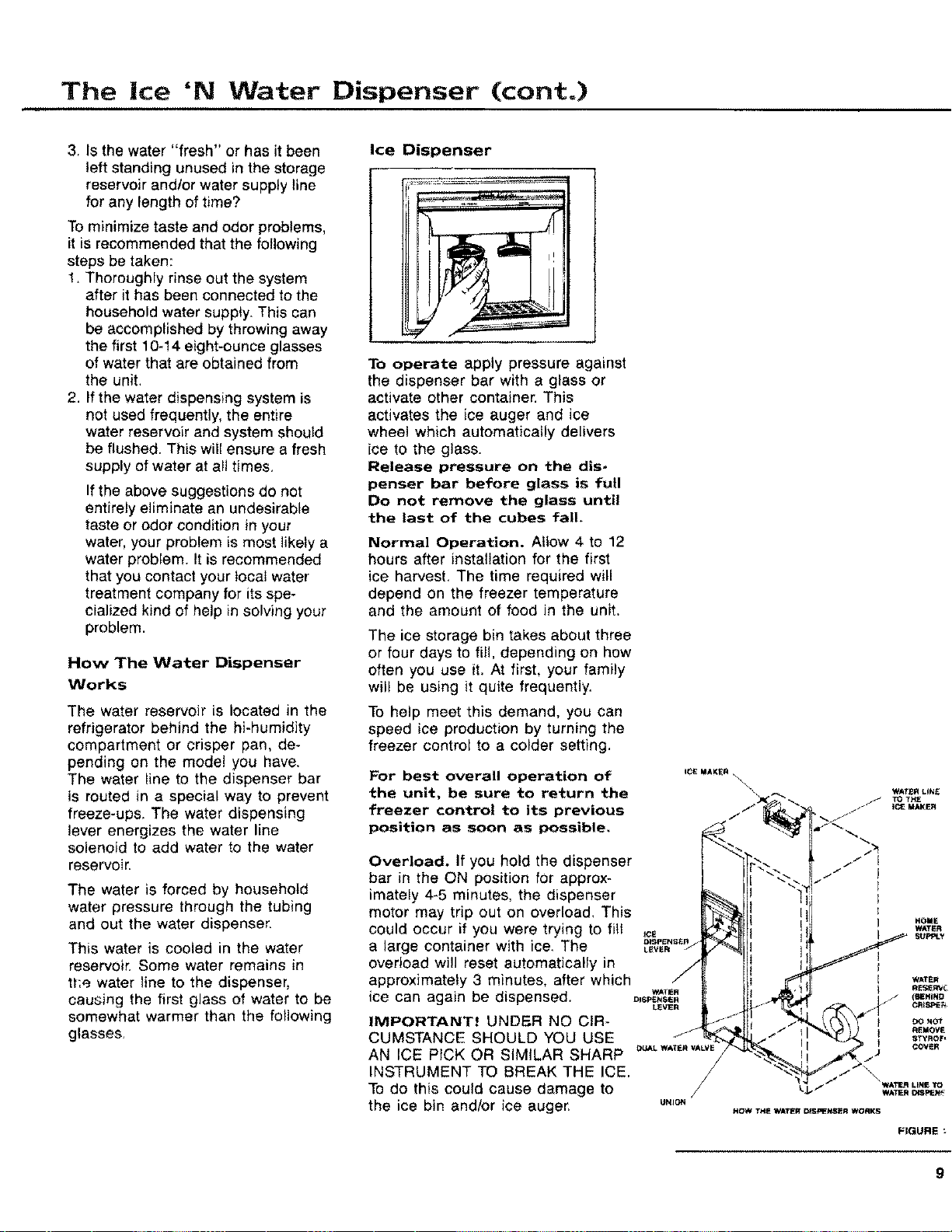
Ice Dispenser
To operate apply pressure against
the dispenser bar with a glass or
activate other container. This
activates the ice auger and ice
wheel which automatically delivers
ice to the glass.
Release pressure on the dis-
penser bar before glass is full
Do not remove the glass until
the last of the cubes fall.
Normal Operation. Allow 4 to 12
hours after installation for the first
ice harvest. The time required will
depend on the freezer temperature
and the amount of food in the unit.
The ice storage bin takes about three
or four days to fill, depending on how
often you use it. At first, your family
will be using it quite frequently.
To help meet this demand, you can
speed ice production by turning the
freezer control to a colder setting.
For best overall operation of _c_=_KE.x
the unit, be sure to return the _',
)
freezer control to its previous /-/
position as soon as possible,
Overload. If you hold the dispenser
bar in the ON position for approx-
imately 4-5 minutes, the dispenser
motor may trip out on overload, This
could occur if you were trying to fill _
a large container with ice. The ._r_,_v_.'7
overload will reset automatically in
/
approximately 3 minutes, after which /
ice can again be dispensed. D_SpE._,W_"
LEVER
IMPORTANT! UNDER NO CIR .... -_
CUMSTANCE SHOULD YOU USE _
AN ICE PICK OR SIMILAR SHARP _,'LW*T._A_VE
/
INSTRUMENT TO BREAK THE ICE. /
TOdo this could cause damage to
the ice bin and/or ice auger, u._o.
HOI_E
WATI_R
HOW THE WATER DISPENSER WORKS
FIGURE
9
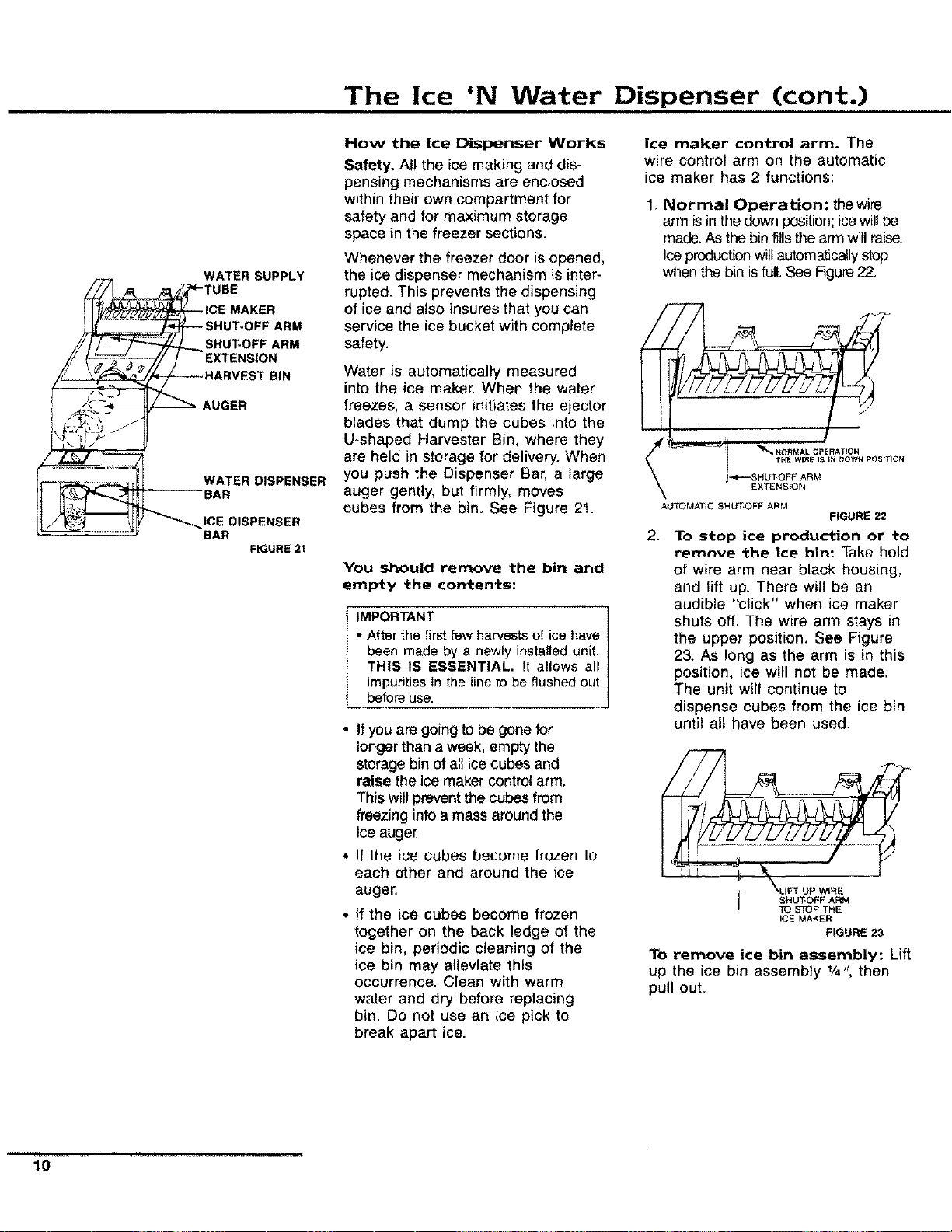
The Ice 'N Water Dispenser (cont.)
WATER SUPPLY
ARM
SHUT-OFF ARM
EXTENSION
BIN
AUGER
WATER DISPENSER
BAR
DISPENSER
BAR
FIGURE 21
How the Ice Dispenser Works
Safety. All the ice making and dis-
pensing mechanisms are enclosed
within their own compartment for
safety and for maximum storage
space in the freezer sections.
Whenever the freezer door is opened,
the ice dispenser mechanism is inter-
rupted. This prevents the dispensing
of ice and also insures that you can
service the ice bucket with complete
safety.
Water is automatically measured
into the ice maker. When the water
freezes, a sensor initiates the ejector
blades that dump the cubes into the
U-shaped Harvester Bin, where they
are held in storage for delivery. When
you push the Dispenser Bar, a large
auger gently, but firmly, moves
cubes from the bin. See Figure 2!.
You should remove the bin and
empty the contents:
IMPORTANT
" After the first few harvests of ice have
been made by a newly installed unit.
THIS tS ESSENTIAL, It allows all
impurities in the line to be flushed out
before use.
• If you are going to be gone for
longer than a week, empty the
storage bin of all ice cubes and
raise the ice maker control arm.
This will prevent the cubes from
freezing into a mass around the
ice auger.
• if the ice cubes become frozen to
each other and around the ice
auger.
* if the ice cubes become frozen
together on the back ledge of the
ice bin, periodic cleaning of the
ice bin may alleviate this
occurrence. Clean with warm
water and dry before replacing
bin. Do not use an ice pick to
break apart ice.
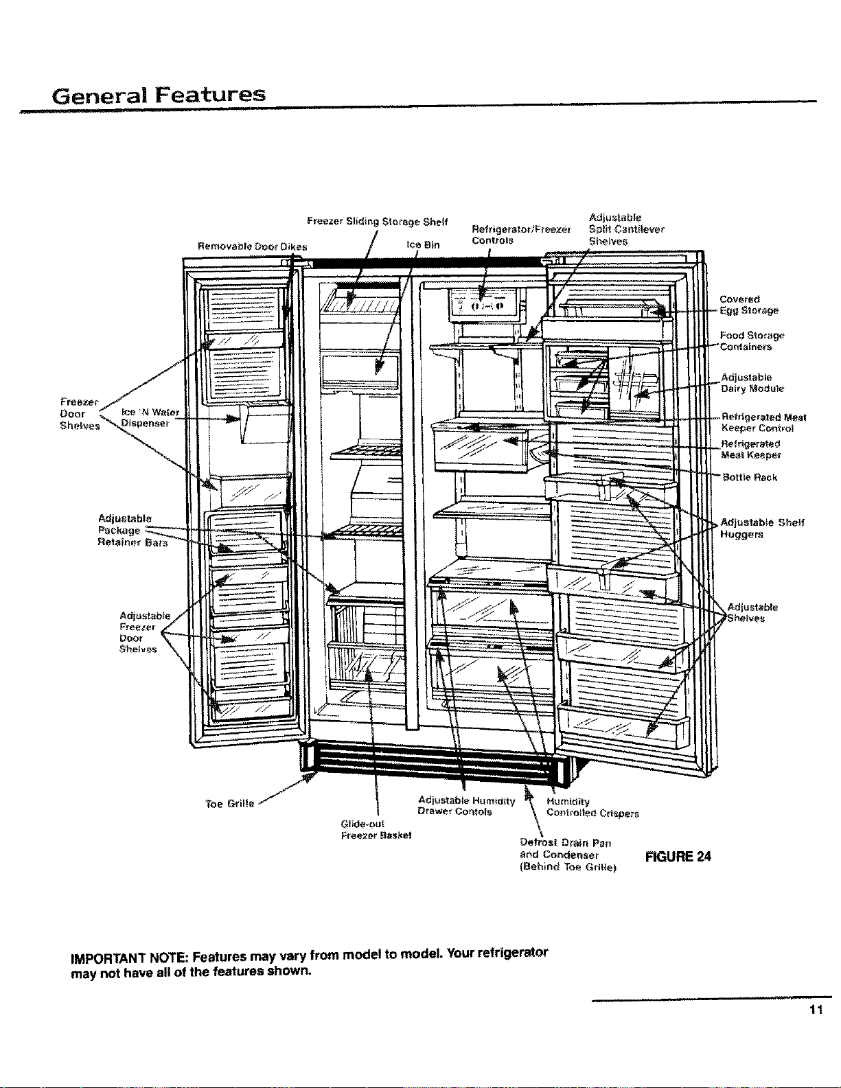
ice maker control arm. The
wire control arm on the automatic
ice maker has 2 functions:
1, Normal Operation: thewire
arm isin the down position;icewill be
made. As the bin fillsthe arm willraise,
Ice production will automatically stop
when the bin is full. See Figure22.
AUTOMATIC SHUT.OFF ARM
' _.O.MALOPE.ATIO.
THE WIRE I_ IN DOWN POSITION
)-,=P--SHUtOFF ARM
EXTENSION
FIGURE 22
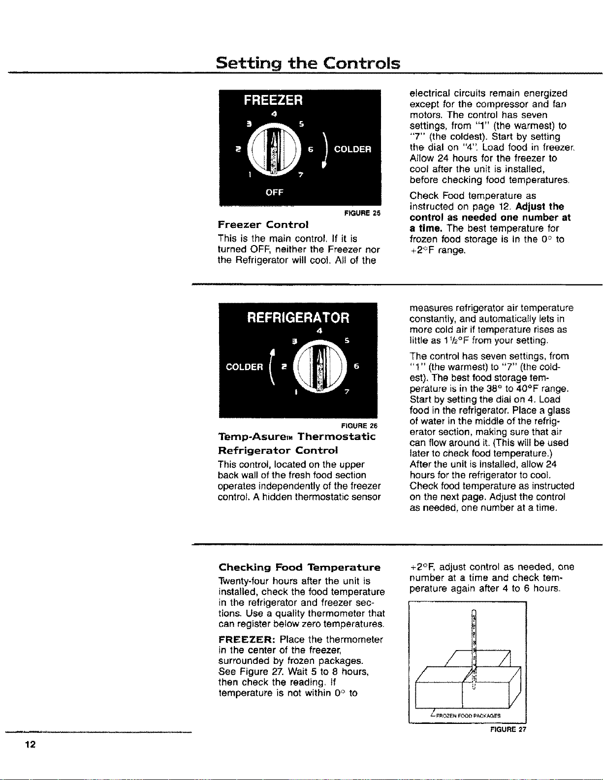
2.
To stop ice production or to
remove the ice bin: Take h01d
of wire arm near black housing,
and lift up. There will be an
audible "click" when ice maker
shuts off. The wire arm stays in
the upper position. See Figure
23. As long as the arm is in this
position, ice will not be made.
The unit will continue to
dispense cubes from the ice bin
until all have been used.
..... J TO STOP THE
ICE MAKER
FIGURE 23
To remove ice bin assembly: Lift
up the ice bin assembly 1/4", then
pull out.
10
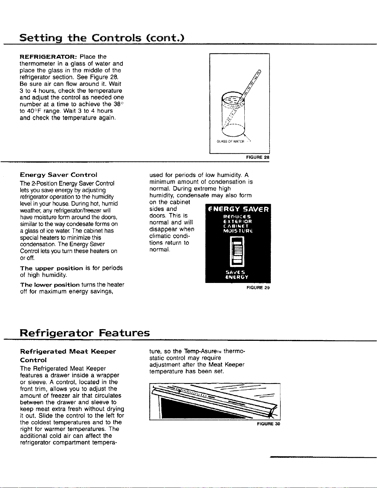
General Features
i Ill
Food Storage
OefroslDrain Pan
and Condenser FIGURE
(Behind Toe Grille)
IMPORTANT NOTE: Features may vary from model to model. Your refrigerator
may not have all of the features shown.
,,,.... i i,
11
Setting the Controls
FIGURE 25
Freezer Control
This is the main control, If it is
turned OFF, neither the Freezer nor
the Refrigerator witl cool. All of the
FIGURE 26
electrical circuits remain energized
except for the compressor and fan
motors. The control has seven
settings, from "1" (the warmest) to
"7" (the coldest). Start by setting
the dial on "4". Load food in freezer,
Allow 24 hours for the freezer to
cool after the unit is installed,
before checking food temperatures,
Check Food temperature as
instructed on page 12. Adjust the
control as needed one number at
a time. The best temperature for
frozen food storage is in the 0 ° to
+2_F range,
Temp-AsureT. Thermostatic
Refrigerator Control
This control, located on the upper
back wall of the fresh food section
operates independently of the freezer
control. A hidden thermostatic sensor
measures refrigerator air temperature
constantly, and automatically tets in
more cold air if temperature rises as
little as 172°F from your setting,
The control has seven settings, from
"1" (the warmest) to "7" (the cold-
est), The best food storage tem-
perature is in the 38 ° to 40°F range.
Start by setting the dial on 4. Load
food in the refrigerator. Place a glass
of water in the middle of the refrig-
erator section, making sure that air
can flow around it. (This wilt be used
later to check food temperature.)
After the unit is installed, allow 24
hours for the refrigerator to cool.
Check food temperature as instructed
on the next page, Adjust the control
as needed, one number at a time,
12
Checking Food Temperature
Twenty-four hours after the unit is
installed, check the food temperature
in the refrigerator and freezer sec-
tions. Use a quality thermometer that
can register below zero temperatures.
FREEZER: Place the thermometer
in the center of the freezer,
surrounded by frozen packages.
See Figure 27. Wait 5 to 8 hours,
then check the reading. If
temperature is not within 0° to
+2°F, adjust control as needed, one
number at a time and check tem-
perature again after 4 to 6 hours.
FIGURE 27
Setting the Controls (cont.)
REFRIGERATOR: Place the
thermometer in a glass of water and
place the glass in the middle of the
refrigerator section, See Figure 28,
Be sure air can flow around it+Wait
3 to 4 hours, check the temperature
and adjust the control as needed one
number at a time to achieve the 38 '>
to 40°F range, Wait 3 to 4 hours
and check the temperature again.
G_ASS OF WA_ R
FIGURE 28
Energy Saver Control
The 2-Position Energy Saver Control
lets you save energy by adjusting
refrigerator operation to the humidity
level in your house. Dudng hot, humid
weather, any refrigeratortfreezer will
have moisture form around the doors,
similar to the way condesate forms on
a glass of ice water.The cabinet has
special heaters to minimize this
condensation. The Energy Saver
Control lets you turn these heaters on
or off.
The upper position is for periods
of high humidity.
The lower position turns the heater
off for maximum energy savings,
used for periods of low humidity. A
minimum amount of condensation is
normal. During extreme high
humidity, condensate may also form
on the cabinet
sides and
doors, This is
normal and will
disappear when
climatic condi-
tions return to
normal.
Refrigerator Features
Refrigerated Meat Keeper
Control
The Refrigerated Meat Keeper
features a drawer inside a wrapper
or sleeve, A control, located in the
front trim, allows you to adjust the
amount of freezer air that circulates
between the drawer and sleeve to
keep meat extra fresh without drying
it out, Slide the control to the left for
the coldest temperatures and to the
right for warmer temperatures. The
additional cold air can affect the
refrigerator compartment tempera-
ture, so the Temp-AsureTMthermo-
static control may require
adjustment after the Meat Keeper
temperature has been set.
FIGURE 29
FIGURE 30
Refrigerator Features (cont.)
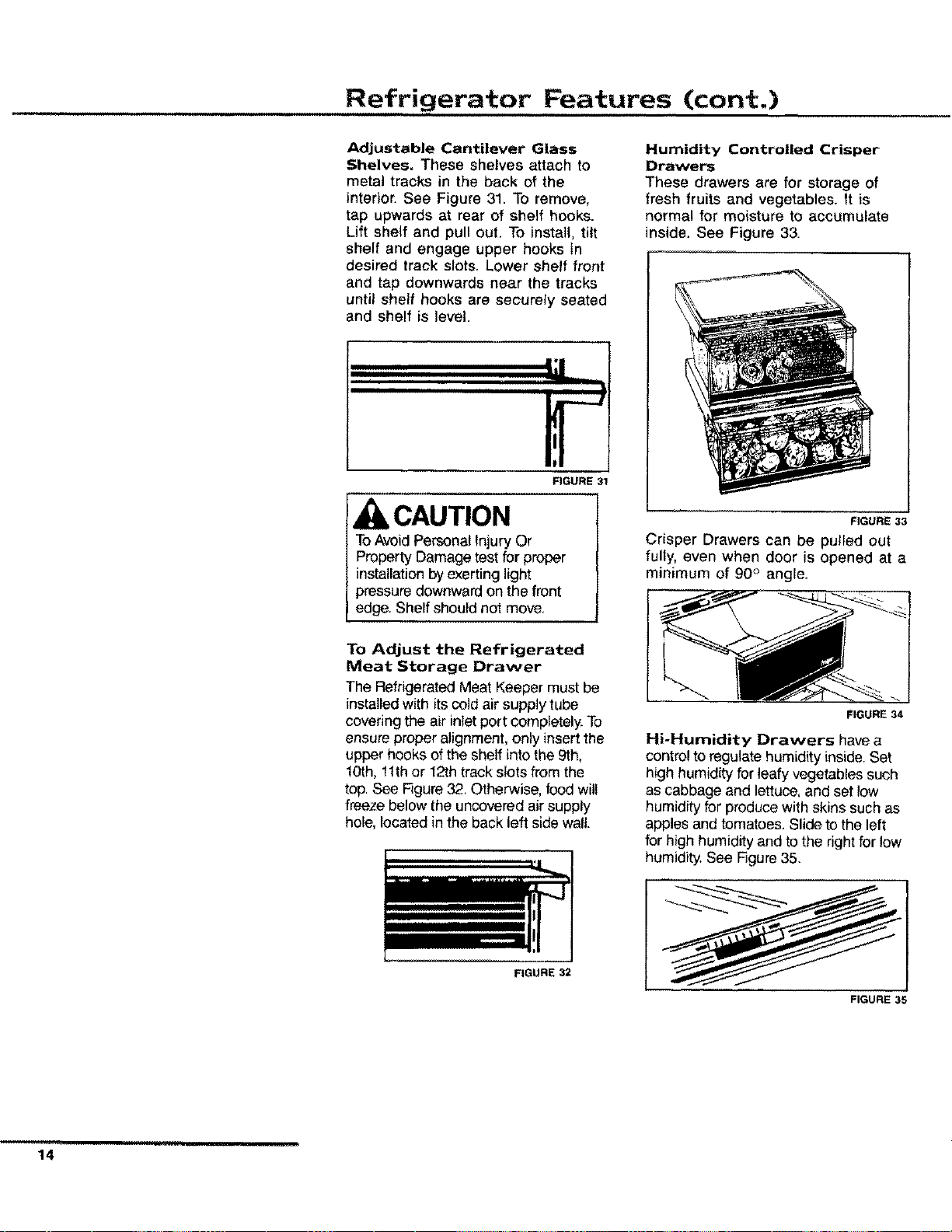
Adjustable Cantilever Glass
Shelves. These shelves attach to
metal tracks in the back of the
interior. See Figure 31. To remove,
tap upwards at rear of shelf hooks.
Lift shelf and pull out, To install, tilt
shelf and engage upper hooks in
desired track slots. Lower shelf front
and tap downwards near the tracks
until shelf hooks are securely seated
and shelf is level.
FIGURE 31
CAUTION
ToAvoidPersonal Injury Or
Property Damage test for proper
installation by exerting light
pressure downward on the front
edge. Shelf should not move,
To Adjust the Refrigerated
Meat Storage Drawer
The RefrigeratedMeat Keeper must be
installed with itscold air supply tube
covering the air inlet port completely. To
ensure proper alignment, only insertthe
upper hooks of the shelf into the 9th,
10th, 11thor 12th track slots from the
top. See Figure 32. Otherwise, food will
freeze below the uncovered air supply
hole, located in the back left side wall.
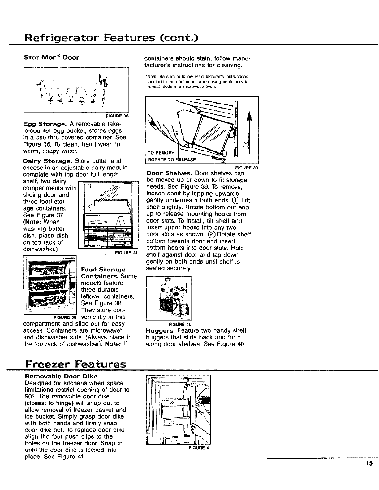
Humidity Controlled Crisper
Drawers
These drawers are for storage of
fresh fruits and vegetables. It is
normal for moisture to accumulate
inside. See Figure 33.
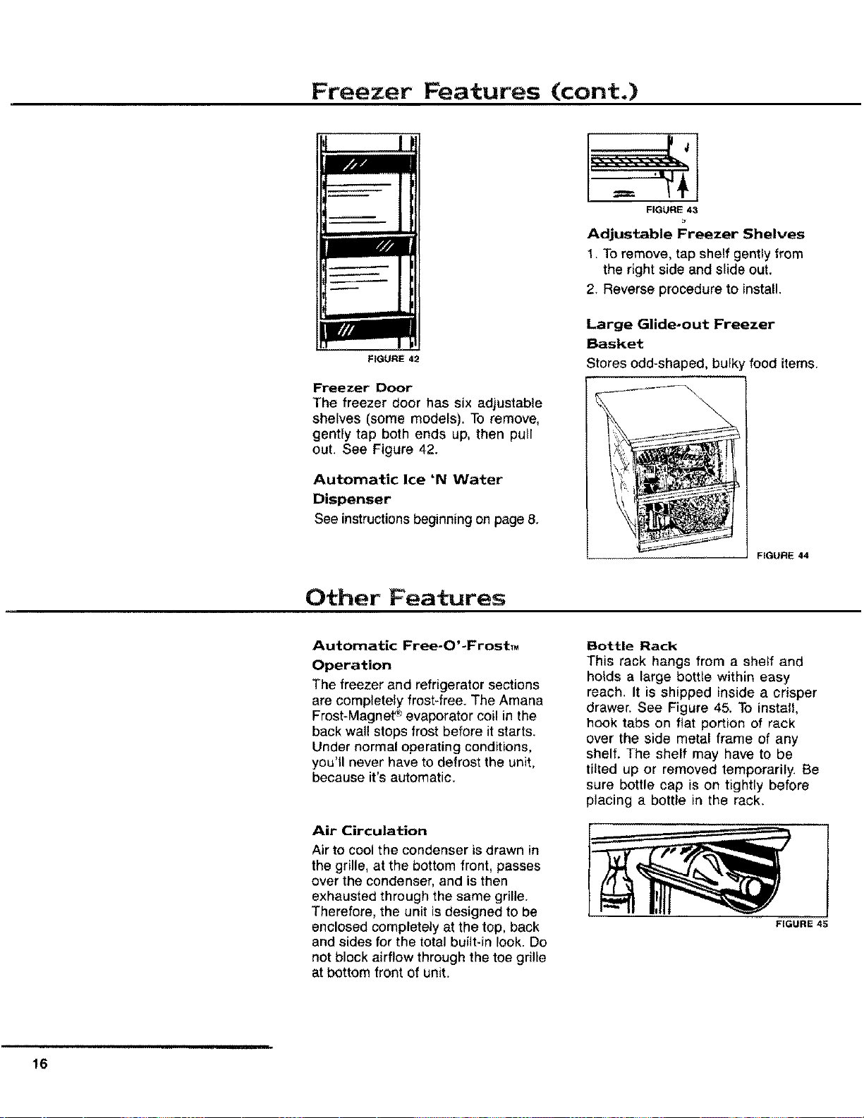
FIGURE 33
Crisper Drawers can be pulled out
fully, even when door is opened at a
minimum of 90 ° angle.
FIGURE 34
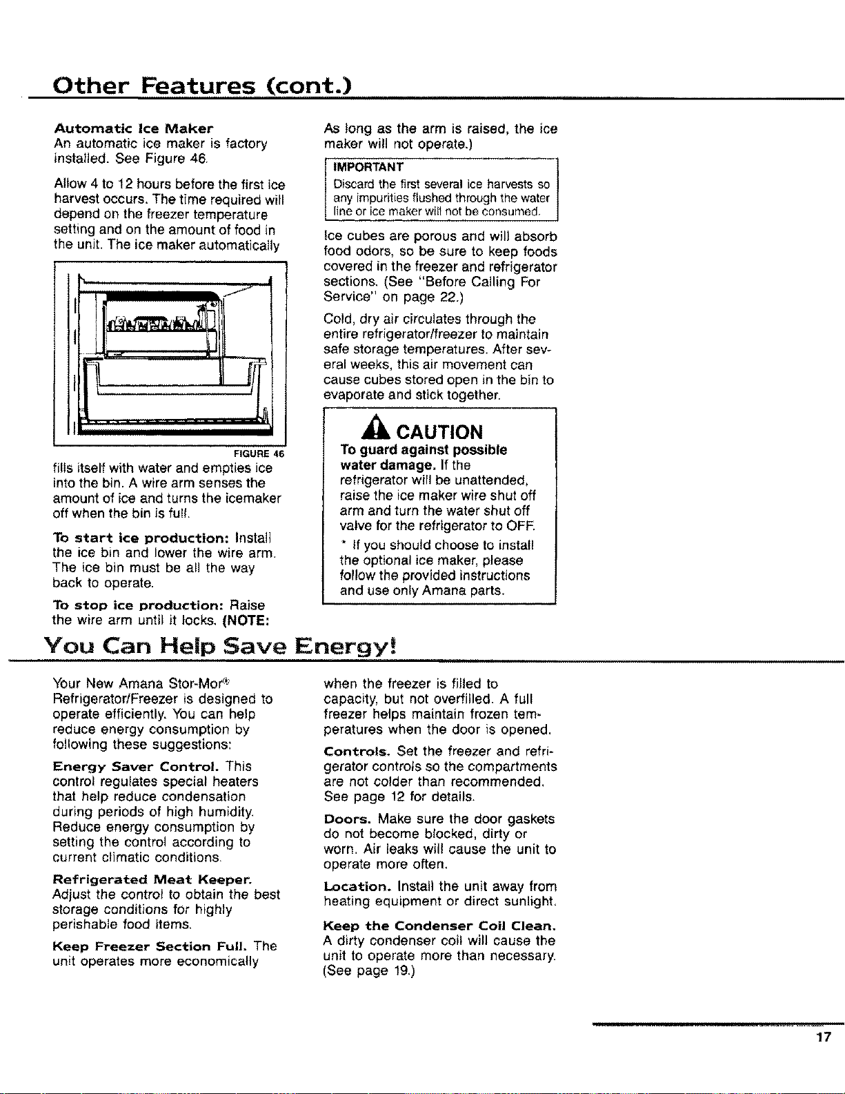
Hi-Humidity Drawers have a
control to regulate humidity inside. Set
high humidity for leafy vegetables such
as cabbage and lettuce, and set low
humidity for produce with skins such as
apples and tomatoes, Slide to the left
for high humidity and to the right for low
humidity. See Figure 35.
FIGURE 32
FIGURE 35
......... i_,ruuul
14
Refrigerator Features (cont.)
Stor-Mor®Door
FIGURE 36
Egg Storage. A removable take-
to-counter egg bucket, stores eggs
in a see-thru covered container. See
Figure 36. To clean, hand wash in
warm, soapy water,
FIGURE 37
Dairy Storage. Store butter and
cheese in an adjustable dairy module
complete with top door full length
shelf, two dairy
compartments with
sliding door and
three food stor-
age containers.
See Figure 37.
(Note: When
washing butter
dish, place dish
on top rack of
dishwasher.
Food Storage
Containers. Some
models feature
three durable
leftover containers.
See Figure 38,
They store con-
FIGURE38 veniently in this
compartment and slide out for easy
access, Containers are microwave*
and dishwasher safe. (Always place in
the top rack of dishwasher). Note: If
containers should stain, follow manu-
facturer's instructions for cleaning.
*Note: Be sure to follow manufacturer's tnstruc;ion$
located in the containers when u_ng containers to
reheat foods in a microwave OVen.
TO REMOVE
ROTATE TO RELEASE
FIGURE 39
Door Shelves. Door shelves can
be moved up or clown to fit storage
needs. See Figure 39. To remove,
loosen shelf by tapping upwards
gently underneath both ends, _) Lift
shelf slightly. Rotate bottom out and
up to release mounting hooks from
door slots. To install, tilt shelf and
insert upper hooks into any two
door slots as shown. (_)Rotate shelf
bottom towards door and insert
bottom hooks into door slots. Hold
shelf against door and tap down
gently on both ends until shelf is
seated securely.
FIGURE 40
Huggers. Feature two handy shelf
huggers that slide back and forth
along door shelves. See Figure 40.
Freezer Features
Removable Door Dike
Designed for kitchens when space
limitations restrict opening of door to
90o. The removable door dike
(closest to hinge) will snap out to
allow removal of freezer basket and
ice bucket. Simply grasp door dike
with both hands and firmly snap
door dike out. To replace door dike
align the four push clips to the
holes on the freezer door. Snap in
until the door dike is locked into
place, See Figure 41.
FIGURE 41
15
Freezer Features (cont.)
FIGURE 42
Freezer Door
The freezer door has six adjustable
shelves (some models). To remove,
gently tap both ends up, then pull
out. See Figure 42.
Automatic Ice 'N Water
Dispenser
See instructions beginning on page 8.
FIGURE 43
Adjustable Freezer Shelves
1. To remove, tap shelf gently from
the right side and slide out,
2. Reverse procedure to install.
Large Glide-out Freezer
Basket
Stores odd-shaped, bul_
'food items.
FIGURE 44
Other Features
Automatic Free-O'-FrostTM
Operation
The freezer and refrigerator sections
are completely frost-free. The Amana
Frost-Magnet _">evaporator coil in the
back wall stops frost before it starts.
Under normal operating conditions,
you'll never have to defrost the unit,
because it's automatic.
Air Circulation
Air to cool the condenser is drawn in
the grille, at the bottom front, passes
over the condenser, and is then
exhausted through the same grille.
Therefore, the unit isdesigned to be
enclosed completely at the top, back
and sides for the total built-in look. Do
not block airflow through the toe grille
at bottom front of unit.
Bottle Rack
This rack hangs from a sheff and
holds a large bottle within easy
reach. It is shipped inside a crisper
drawer. See Figure 45. To install,
hook tabs on fiat portion of rack
over the side metal frame of any
shelf, The shelf may have to be
tilted up or removed temporarily. Be
sure bottle cap is on tightly before
placing a bottle in the rack.
FIGURE 45
16
Other Features (cont.)
Automatic Ice Maker
An automatic ice maker is factory
installed. See Figure 46.
Allow 4 to 12 hours before the first ice
harvest occurs. The time required will
depend on the freezer temperature
setting and on the amount of food in
the unit. The ice maker automatically
FIGURE 46
fi!ls itself with water and empties ice
into the bin. A wire arm senses the
amount of ice and turns the icemaker
off when the bin is full.
To start ice production: Install
the ice bin and lower the wire arm
The ice bin must be all the way
back to operate.
To stop ice production: Raise
the wire arm until it locks, (NOTE:
As long as the arm is raised, the ice
maker will not operate.)
IMPORTANT
Discard the first several ice harvests so
any impurities flushed through the water
line or ice maker witl not be consumed.
Ice cubes are porous and will absorb
food odors, so be sure to keep foods
covered in the freezer and refrigerator
sections. (See "Before Calling For
Service" on page 22.)
Cold, dry air circulates through the
entire refrigerator/freezer to maintain
safe storage temperatures. After sev-
eral weeks, this air movement can
cause cubes stored open in the bin to
evaporate and stick together.
CAUTION
To guard against possible
water damage. If the
refrigerator will be unattended,
raise the ice maker wire shut off
arm and turn the water shut off
valve for the refrigerator to OFF
* If you should choose to install
the optional ice maker, please
follow the provided instructions
and use only Amana parts.
You Can Help Save Energy!
Your New Amana Stor-Mor _':
Refrigerator/Freezer is designed to
operate efficiently. You can help
reduce energy consumption by
following these suggestions:
Energy Saver Control. This
control regulates special heaters
that help reduce condensation
during periods of high humidity.
Reduce energy consumption by
setting the control according to
current climatic conditions,
Refrigerated Meat Keeper.
Adjust the control to obtain the best
storage conditions for highly
perishable food items.
Keep Freezer Section Full. The
unit operates more economically
when the freezer is filled to
capacity, but not overfilled. A full
freezer helps maintain frozen tem-
peratures when the door is opened.
Controls. Set the freezer and refri-
gerator controls so the compartments
are not colder than recommended,
See page 12 for details.
Doors. Make sum the door gaskets
do not become blocked, dirty or
worn. Air leaks will cause the unit to
operate more often.
Location. Install the unit away from
heating equipment or direct sunlight,
Keep the Condenser Coil Clean.
A dirty condenser coil will cause the
unit to operate more than necessary.
(See page 19,)
17
Care & Cleaning
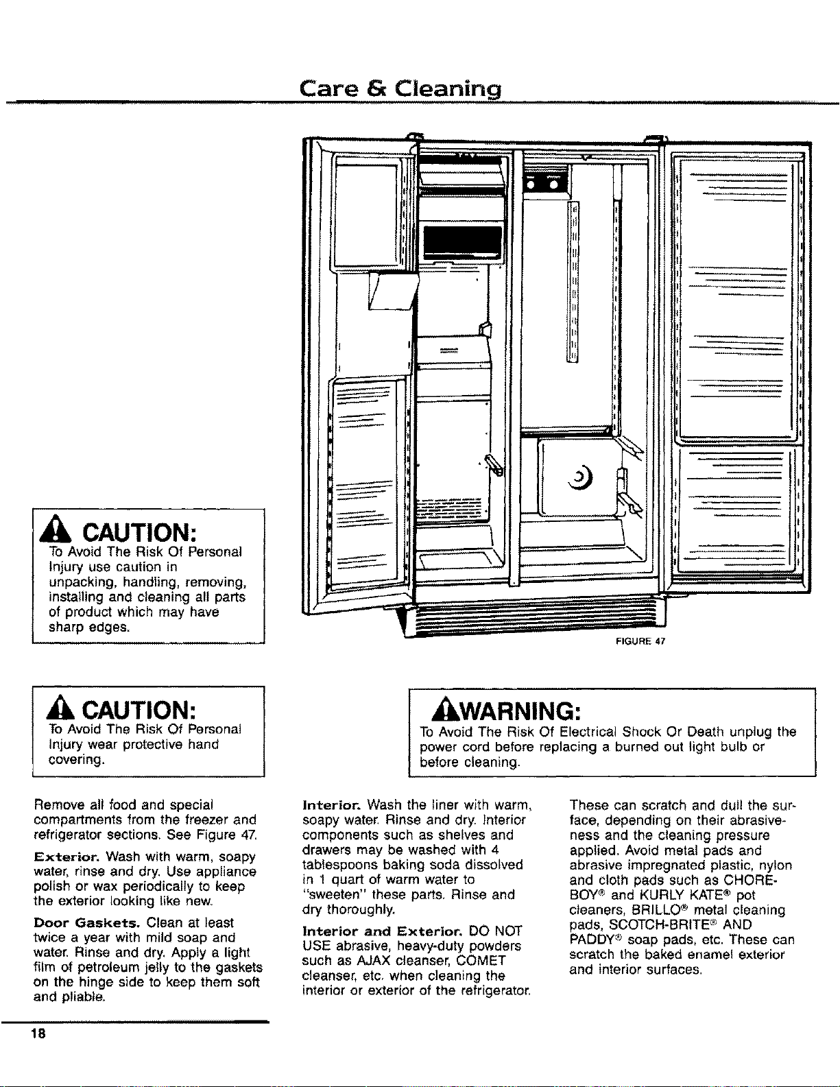
CAUTION:
To Avoid The Risk Of Personal
Injury use caution in
unpacking, handling, removing,
installing and cleaning all parts
of product which may have
sharp edges.
L .................
FIGURE 47
CAUTION:
To Avoid The Risk Of Personal
injury wear protective hand
covering.
WARNING:
To Avoid The Risk Of Electrical Shock Or Death unplug the
power cord before replacing a burned out light bulb or
before cleaning.
Remove all food and special
compartments from the freezer and
refrigerator sections. See Figure 47,
Exterior. Wash with warm, soapy
water, rinse and dry. Use appliance
polish or wax periodically to keep
the exterior looking like new.
Door Gaskets. Clean at least
twice a year with mild soap and
water. Rinse and dry, Apply a light
film of petroleum jelly to the gaskets
on the hinge side to keep them soft
and pliable.
Interior. Wash the liner with warm,
soapy water, Rinse and dry. Interior
components such as shelves and
drawers may be washed with 4
tablespoons baking soda dissolved
in 1 quart of warm water to
"sweeten" these parts, Rinse and
dry thoroughly.
Interior and Exterior. DO NOT
USE abrasive, heavy-duty powders
such as AJAX cleanser, COMET
cleanser, etc, when cleaning the
interior or exterior of the refrigerator.
These can scratch and dull the sur-
face, depending on their abrasive-
hess and the cleaning pressure
applied. Avoid metal pads and
abrasive impregnated plastic, nylon
and cloth pads such as CHORE-
BOY® and KURLY KATE® pot
cleaners, BRILLO ® metal cleaning
pads, SCOTCH-BRITE c"_AND
PADDY ® soap pads, etc. These can
scratch the baked ename! exterior
and interior surfaces.
,,,,,
18
Care and Cleaning (cont.)
Do not use concentrated liquid
dishwashing detergent (dissolve in
warm water before using), abrasive
cleaners, solvents or polishing
agents on plastic parts, These
cleansers may cause cracking or
discoloration.
Do not wash plastic parts in an
automatic dishwasher. They may
warp. (The butter dish and food
storage containers can be washed
in a dishwasher. See page 15 for
details.)
Ice Maker. If your water has a
high mineral content, the ice maker
may require periodic cleaning.
Cleaning with vinegar should
remove most of the build*up.
Contact your dealer for assistance
with ice maker removal, cleaning
and reinstallation, An in-line
water filter may also be necessary.
Clean Defrost Drain Pan. The
pan is located underneath the unit
behind the toe grille. Every three
months, remove the drain pan, wash
it with warm soapy water, rinse and
dry. When replacing the pan, make
sure it is directly underneath the
defrost water tube that extends from
the back of the unit. Pull the toe
grille forward to remove.
Clean Condenser Coil. The con-
denser coil is located behind the toe
grille. Use a long-handled bottle
brush and a vacuum cleaner to
remove dust and lint from the coil,
A suitable brush can be purchased
from your Amana dealer. Dust and
lint act as an insulator and prevent
the coil from expelling heat taken
from inside the unit. Failure to keep
the coil clean will reduce cooling
performance and efficiency.
Reconnect Power Cord. After
cleaning, reconnect the power cord.
Odors. If an offensive odor appears
to be lingering in the refrigerator or
freezer, the following procedures
may eliminate the problem. Always
begin with Method L Use Method II
and III only if the odor persists.
Method I
1. Unplug the Unit
2. Remove all food
3. Thoroughly wash the inside of the
unit, including all shelves, drawers,
accessories and gaskets with a mix-
ture of 4 tablespoons of baking soda
dissolved in 1 quart of warm water.
Pay special attention to any corners,
crevices or grooves into which odors
causing liquid may have seeped, Dry
thoroughly.
4. Return food to unitwashing off all
bottles, jars and containers before
placing them into the refrigerator and
freezer.
5. Plug in the unit. Wait 24 hours
before checking to see if the odor has
been eliminated, if the odor is still
present, proceed with Method IL
Method !!
1. Unplug the unit,
2. Remove all food, making ar-
rangements for other food storage.
(The inside of the unit should
already have been washed as
instructed in Method I.)
3. Place crisper drawers on the top
shelf of the refrigerator section.
4. Lightly crumple single sheets of
newspaper. Loosely pack and fi!l
entire refrigerator and freezer
interior with newspapers including
door shelves, drawers and
compartments.
5. Randomly place charcoal bri-
quettes throughout both compart-
ments on the crumpled newspaper.
6. Close the doors and let stand for
24 to 48 hours.
7. Remove the charcoal briquettes
and newspapers. Wash and dry the
inside of the unit as described in
Method L
8. Plug in the unit. Wait for 24
hours before checking to see if the
odor has been eliminated then
replace the food. If the odor
persists, proceed with Method I11.
Method I!1
Order Delta Foremost's Original
Country Club Cherry (a commercial
neutralizing aerosal) from your
nearest Amana authorized service
center (Part number Rf831-6). Use
according to instructions packaged
with the aerosal, Remember to
unplug the unit before beginning.
19
Non-Use Periods
Vacation Time. If you will be
away for vacation, remove perishable
foods from the unit. Shut off the ice
maker by turning off the water
supply to the refrigerator and
moving the icemaker wire arm to its
uppermost position.
Extended periods of non-use.
If you are going to be away for
longer periods, empty and unplug
the unit. This will reduce needless
operation and assure that food will
not be spoiled if electrical service is
interrupted Just clean the unit as
instructed in this manual and prop
open the doors so air can circulate
inside, Leave the unit unplugged. If
the refrigerator has an automatic
icemaker, turn off the water supply
to the refrigerator.
When You Move. Unplug the unit
and clean it. Use strapping tape or
masking tape to secure all trays,
shelves and other parts to prevent
damage during shipment. Do not
leave the unit closed for an
extended period of time.
CAUTION:
To Avoid Property Damage do
NOT use tape that has
"permanent" type adhesive.
If The Refrigerator Will
Be Stored.
If the refrigerator will be stored or
remain unused in a sub-freezing
environment, remove the water and
protect the water valve from damage
as follows:
1. Disconnect the refrigerator from
the electrical power source.
2. Shut off the refrigerator water
supply. This can be done at the
saddle valve with the 1/4" copper
supply tubing joins the household
water line, For factory installed
ice makers, refer to illustration
on back of cabinet. For all other
ice makers, refer to installation
instructions.
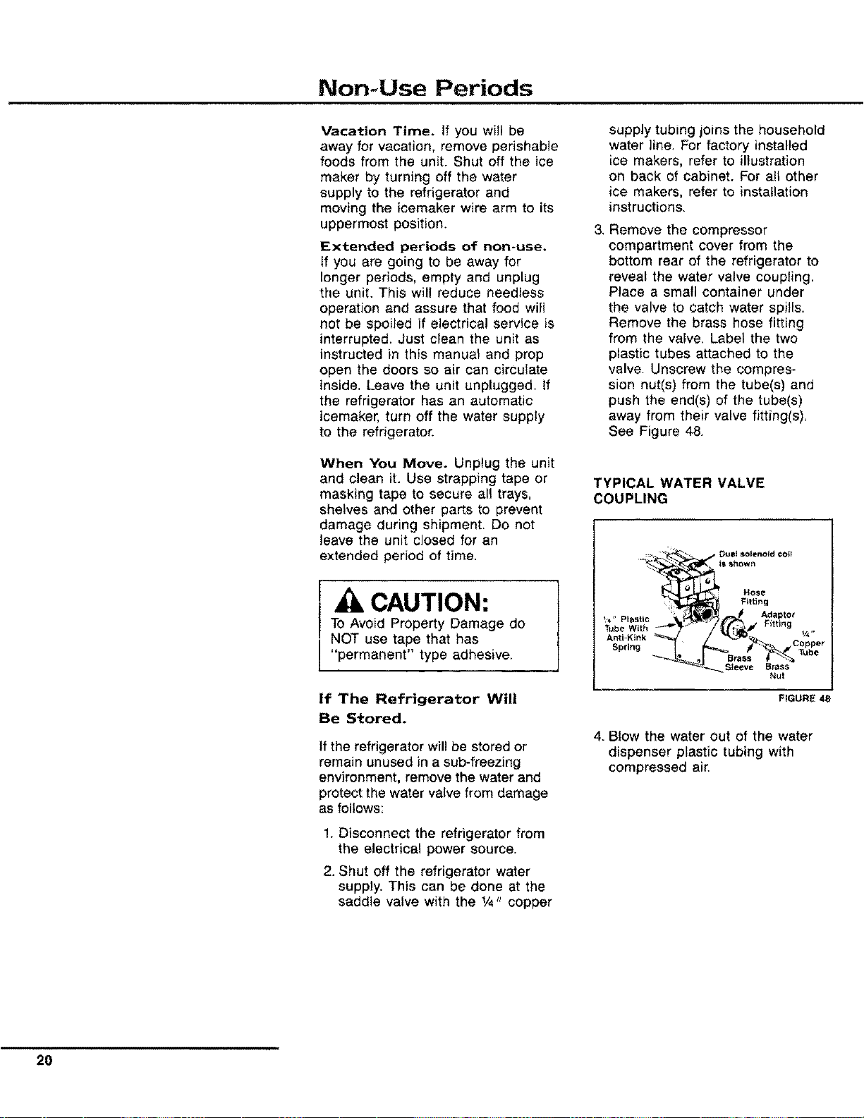
3. Remove the compressor
compartment cover from the
bottom rear of the refrigerator to
reveal the water valve coupling.
Place a small container under
the valve to catch water spills.
Remove the brass hose fitting
from the valve, Label the two
plastic tubes attached to the
valve. Unscrew the compres-
sion nut(s) from the tube(s) and
push the end(s) of the tube(s)
away from their valve fitting(s),
See Figure 48.
TYPICAL WATER VALVE
COUPLING
,_. _ _. DUOt _iolenold COlt
_ Hose
:: Fitting
_ _aptor
Tube With
Sleeve
Brass
Nut
FIGURE 48
4. Blow the water out of the water
dispenser plastic tubing with
compressed air.
20
Normal Operating Sounds of Today's Modern Refrigerators
i, i,,
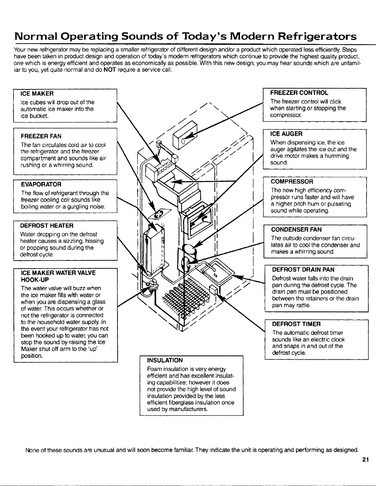
Your new refrigerator may be replacing a smaller refrigerator of different design andlor a product which operated lessefficiently Steps
have been taken in product design and operation of today's modern refrigerators which continue to provide the highest quality product,
one which is energy efficient and operates as economically as possible. With this new design, you may hear sounds which are unfamil-
iar to you, yet quite normal and do NOT require a service call.
ICE MAKER !
Ice cubes willdrop out of the
automatic ice maker into the
ice bucket.
FREEZER FAN
The fan circulates cold air to cool
the refrigerator and the freezer
compartment and sounds like air
rushing or a whirring sound.
EVAPORATOR
The flow of refrigerant throughthe
freezer cooling coil sounds like
boiling water or a gurgling noise.
DEFROST HEATER
Water dropping on the defrost
heater causes a sizzling, hissing
or popping sound during the
defrost cycle.
ICE MAKER WATER VALVE
HOOK-UP
The watervalve will buzz when
the ice maker fills with water or
when you are dispensing a glass
of water. This occurs whether or
not the refrigerator is connected
to the household water supply In
the event your refrigerator has not
been hooked up to water, you can
stop the sound by raising the Ice
Maker shut off arm to the 'up'
position.
INSULATION
Foam insulation is very energy
efficient and has excellentinsulat-
ing capabilities; however it does
not provide the high level of sound
insulation provided by the less
efficientfiberglass insulation once
used by manufacturers.
FREEZER CONTROL J
The freezer control will click
when starting or stopping the
compressor.
ICE AUGER
When dispensing ice, the ice
auger agitates the ice out and the
drive motor makes a humming
sound,
COMPRESSOR
The new high efficiency com-
pressor runs faster and will have
a higher pitch hum or pulsating
sound while operating.
CONDENSER FAN
The outside condenser fancircu-
lates air to cool the condenser and
makes a whirring sound.
DEFROST DRAIN PAN
Defrost water falls into the drain
pan during the defrost cycle. The
drain pan must be positioned
between the retainers or the drain
pan may raffie.
DEFROST TIMER
The automatic defrost timer
sounds like an electric clock
and snaps in and out of the
defrost cycle.
None of these sounds are unusual and will soon become familiar. They indicate the unit is operating and performing as designed.
21
Before Calling For Service
Unnecessary service calls may be
avoided by checking for the follow_
ing common sources of difficulty.
You will be charged for a service-
man's travel expenses and labor,
even though the product may be in
warranty, if the difficulty is not
caused by workmanship or material,
or if the component is customer
replaceabfe. The following items are
considered customer replaceable:
defrost drain pan, door and cabinet
shelves and drawers, butter dish,
ice trays, light bulbs, egg bucket,
huggers and accessories.
Your refrigerator/freezer is
designed for operation in a
conditioned environment. For
best performance your refrig-
erator should not be installed
where surrounding tempera-
tures will be lower than 55
degrees IF. The compressor
will not run frequently enough
to maintain proper tempera-
ture. Operation in surrounding
temperatures below 32
degree F. will result in
defrosting problems and is not
recommended for self defrost-
ing products.
If product does not appear to
be operating:
• Does the light work? A dim light
indicates low voltage or a weak
bulb,
• Is the cord plugged in?
• Is a fuse or circuit breaker open?
Check by plugging in another
appliance or lamp at the same
wall outlet,
• Has either of the doors been left
open? Make certain food items
stored within the refrigerator are
not obstructing proper door
closure. Check leveling of unit.
(See page 5.)
• If the lights work and the freezer
control is on, but the fan and
compressor are not operating, the
unit is likely in the defrost cycle,
Wait 30 minutes to see if the unit
witl restart. If it does not, remove
the toe grille. The defrost timer is
located behind the grille, Turn the
timer knob clockwise until you
hear a click. The refrigerator
should begin running.
If the unit still won't operate:
• Be sure you have completed the
steps listed above.
• Take the steps necessary to
preserve the food stored in the
unit. Dry ice may be placed in the
freezer section of the unit to
preserve food until the unit can
be serviced, Doors should be left
closed until the unit has been
repaired. Your product warranty
does not cover food loss.
• Call your nearest Amana dealer
or authorized service center listed
in the Yellow pages.
If food temperature appears
to be warm:
• See prior sections.
• Have you recently added a large
load of food? Allow adequate time
for the food to reach freezing
temperature.
• Are any shelves covered with foil
or plastic, preventing proper air
flow?
• Is the condenser area clean?
(See page !9,)
• Adjust freezer control.
(See page 12.)
If refrigerator section is too
warm:
• See prior sections.
• Adjust Temp-Asure refrigerator
control. (See page 12.)
If the Refrigerated Meat
Keeper is too warm:
• Is Meat Keeper inlet tube in place
with the control outlet tube on the
side wall?
• Slide Meat Keeper control to
colder setting,
,, Adjust freezer control to colder
setting.
If refrigerator food
temperature is too cold:
• Check Refrigerator Meat Keeper
drawer assembly to see that
outlet tube is in proper place over
the inlet hole on side wall, If it is
not properly connected, freezer air
will spill into the refrigerator section.
(See page 14).
• Is condenser area clean?
(See page 19)
• Are any shelves covered with foil
or plastic, preventing proper air
flow?
22
Before Calling For Service (cont.)
• Adjust Temp-Asure refrigerator
control. (See page 12.)
• Adjust freezer control to warmer
setting. Allow several hours for
temperature to change.
If the unit runs too much or
too frequently:
,_ It may be normal to maintain an
even temperature.
• Is condenser area clean?
(See page 19.)
t Have doors been opened
frequently or for an extended
period of time?
• Is freezer running too cold? Adjust
freezer control, (See page 12.)
• Check door alignment and gasket
seal for proper closure.
If the unit makes unfamiliar
sounds such as popping or
cracking; tapping, gurgling,
boiling or bubbling; rumbling
or rattling on shutdown:
• These may be normal operating
sounds. Refer to page 17 for in-
formation on sounds the unit may
make.
If you hear running water in
the unit:
• This is normal when the icemaker
fi!ls.
• This is normal when the unit
defrosts and water enters the
condensate pan,
If you hear periodic buzzing:
• This is normal in cabinets with an
automatic icemaker. The water
valve will buzz when energized to
refill the icemaker.
If condensate forms on the
inside of the unit:
• This is highly normal during
periods of high humidity.
If condensate forms on the
outside of the unit:
• IS Energy Saver Control on
highest setting? This will help
reduce condensate,
• Check door alignment and gasket
seal for proper closure.
If Crisper or Meat Keeper
drawers do not close freely:
• Check for package obstructing
proper closure.
• Check to confirm drawer is in
proper position in assembly.
• Apply thin layer of petroleum jelly
to slide channels.
• Make sure refrigerator is level.
If there is an odor in the unit
or ice cubes:
• Clean product (See page 19.)
• Cover all foods tightly,
• Use freezer containers or freezer
wrap.
If ice forms in the inlet tube
to the ice maker:
• Indicates sediment in solenoid
valve which has not allowed the
valve to close. An in-line water
filter should be added. If problem
persists the solenoid valve will
need to be cleaned or changed.
If the Automatic Ice Maker
does not produce ice:
• Check for ice cubes obstructing the
shut-off arm,
• Check to make sure shut-off arm is in
the 'down' position,
IF LIGHT BULB NEEDS
REPLACING:
• Unplug unit from wall outlet to avoid
electrical shock. A pair of gloves
should be worn as a precaution
against broken glass.
Refrigerator Compartment
1, Unscrew the light bulb(s) located
on the front upper wall of the
refrigerator compartment by turning
counterclockwise.
2. Replace with a G.E, or Westing-
house #40A15tl, Sylvania #40A15
or order from your Amana Service
Dept., part number A0282803.
Freezer Compartment (ice "N
Water Model)
To remove the light bulb located on
the right wall of the cavity, directly
below the ice bucket of the upper
freezer compartment, follow the
directions below:
1. Remove the ice maker drawer.
2. Remove the protective shield by
unscrewing the nut with a 1/4_'
drive or socket wrench,
3. Unscrew the light bulb counter-
clockwise.
4. Replace with a G.E or Westing-
house #40A1511, Sylvania #40A15
or order from your Amana Service
Dept., part number A0282803.
23
Before Calling For Service (cont.)
Freezer Compartment
(Conventional Model)
To remove the light bulb located on the
front upper wall of the refrigerator
compartment by turning
counterclockwise.
1. Unscrew the light.
2. Replace with a G.E. or Westinghouse
#40A15/1, Sylvania, #40A15 or order
from your Amana Service Dept., part
number A0282803.
Dispenser Light Bulb (Ice 'N
Water Model)
Should the light bulb ever need to
be replaced, it is located just above
the water dispenser bar.
1. Unscrew the bulb counterclockwise.
2. Replace with a 120 volt, 6 watt
Sylvania 6S6 bulb or order from
your Amana Service Dept., part
number M0360001.
EXTENDED SERVICE PLAN
Rest assured against unexpected repair bills!
Amana is pleased to offer an impor-
tant opportunity for long-term service
protection on your new Amana
appliance. The Amana Asure
Extended Service Plan is specially
designed to supplement the strong
warranty that already accompanies
your appliance, and it combines
with this standard warranty to
provide budget-protecting coverage
on your appliance for up to five full
years, covering parts, labor and
travel charges.
Your participating Amana dealer has
details. Or contact us:
Amana Refrigeration, Inc.
Customer Service Department
Amana, IA 52204
(319) 622-5511
Monday through Friday
(8 a.m.-4:30 p.m., C.S.T.)
1-800-843-0304
TOLL-FREE
'lip
r,L,mbeF
10165808 _eV I :_)1990 Arna_}a fRe_ri_,ratlon Inc
Printed irl U S A A _ Comp_F 5, Am_n_ I_w_ 5_20,'_