Loading ...
Loading ...
Loading ...
17
3. Non-MRV Wall Mount (AW...)
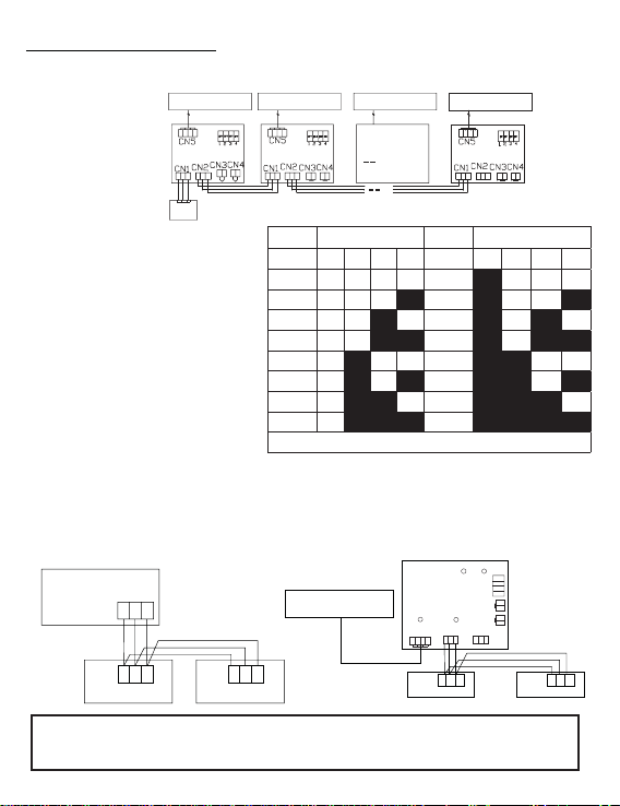
Wiring Connections
SW1
Wired controller
Unit 0
... ...
(main unit)
Unit 1
Unit 15
ABC
AB
B
B
C
C
C
A
A
ABC
AB
C
SW1
SW1
High Wall
WK-B
¤!¥ÝëèĤõö÷ëìêëúäïïìñçòòõøñì÷÷ò
connect with WK-B is considered as
main unit 0.
(2) Remove the jumpers on CN3 and CN4.
(3) The wired control must connect to CN1
of the WK-B main unit (unit 0).
(4) Connect the CN2 on the main unit (unit
0) to the next WK-B subordinate unit
(unit 1) CN1 or CN2. Only the main unit
(unit 0) must use CN1 for the control.
All others may use CN1 or CN2. See
Picture 2.2.
(5) Set the dipswitch address of the WK-B
adapter. The adapters ship with all
öúì÷æëèöòģ¤ðäìñ¥
C:
Two controllers on one indoor
Notice: For wired controller connection and warranty details, please follow
the corresponding indoor unit installation instructions.
LED3/R LED4/G
A
B
C
A
B
C
Wired controller Wired controller
Polar wire
SW1
CN4
CN3
CN5
CN1
A B C
A B C
CN2
1 2 3 4
LED1/R LED2/G
WK-B
Indoor PCB board
"×òñ¡ÖÛßàäïïÖòøñ÷¤Êà¥!Ìäööè÷÷è¤ÊËÊÕÖßÊËÖßÊÕ¥
Íøæ÷èç¤ÊÍÊÖÖßÊÍÖßÊÑ¥
ÖÛßàäïïÖòøñ÷¤ÖßÊà¥
A B C
A B C
A B C
Indoor 1
Wired controller
Polar wire
Wired controller
Polar wire
Wired controller
Dipswitch position Dipswitch position
Unit # 1 2 3 4 Unit # 1 2 3 4
0* òģ òģ òģ òģ 8 on òģ òģ òģ
1 òģ òģ òģ on 9 on òģ òģ on
2 òģ òģ on òģ 10 on òģ on òģ
3 òģ òģ on on 11 on òģ on on
4 òģ on òģ òģ 12 on on òģ òģ
5 òģ on òģ on 13 on on òģ on
6 òģ on on òģ 14 on on on òģ
7 òģ on on on 15 on on on on
* Unit 0 is connected directly to the control and is main
Loading ...
Loading ...
Loading ...