SINGLE-ZONE
VERTICAL AIR HANDLING UNIT
ENGINEERING MANUAL
Single-Zone Vertical Air Handling Unit System
18,000 - 48,000 Btu/h
LV360HV4 (36,000 Btu/h)
LV420HV (42,000 Btu/h)
LV480HV (48,000 Btu/h)
LV180HV4 (18,000 Btu/h)
LV240HV4 (24,000 Btu/h)

For continual product development, LG Electronics U.S.A., Inc., reserves the right to change specifications without notice.
© LG Electronics U.S.A., Inc.
PROPRIETARY DATA NOTICE
This document, as well as all reports, illustrations, data, information,
and other materials are the property of LG Electronics U.S.A., Inc., and are
disclosed by LG Electronics U.S.A., Inc. only in confidence.
This document is for design purposes only.
A summary list of safety precautions is on page 3.
For more technical materials such as submittals, catalogs, installation,
owner’s, and service manuals, visit www.lghvac.com.
TABLE OF CONTENTS
Unit Nomenclature ..........................................................................................................................................................................................................4
LG Air Conditioner Technical Solution (LATS) .........................................................................................................................................................5-6
Vertical Air Handling Unit Product Data ..................................................................................................................................................................7-50
Mechanical Specications ����������������������������������������������������������������������������������������������������������������������������������������������������������������������������������������� 8-9
General Data ��������������������������������������������������������������������������������������������������������������������������������������������������������������������������������������������������������� 10-12
Electrical Data ������������������������������������������������������������������������������������������������������������������������������������������������������������������������������������������������������������ 13
Functions, Controls, and Options �������������������������������������������������������������������������������������������������������������������������������������������������������������������������� 14-15
Dimensions ������������������������������������������������������������������������������������������������������������������������������������������������������������������������������������������������������������ 16-19
Acoustic Data �������������������������������������������������������������������������������������������������������������������������������������������������������������������������������������������������������� 20-30
Refrigerant Flow Diagrams ������������������������������������������������������������������������������������������������������������������������������������������������������������������������������������ 31-32
Wiring Diagrams, Dip Switch Settings ������������������������������������������������������������������������������������������������������������������������������������������������������������������� 33-37
Electrical Connections ������������������������������������������������������������������������������������������������������������������������������������������������������������������������������������������� 38-42
External Static Pressure and Air Flow Ranges ������������������������������������������������������������������������������������������������������������������������������������������������������ 43-47
Accessories ����������������������������������������������������������������������������������������������������������������������������������������������������������������������������������������������������������� 48-50
Vertical Air Handling Unit Performance Data -------------------------------------------------------------------------------------------------------------------------------51-69
Cooling Capacity Data ������������������������������������������������������������������������������������������������������������������������������������������������������������������������������������������� 52-56
Heating Capacity Data ������������������������������������������������������������������������������������������������������������������������������������������������������������������������������������������� 57-61
Maximum Heating Capacity Data �������������������������������������������������������������������������������������������������������������������������������������������������������������������������� 62-66
Equipment Selection Procedure ���������������������������������������������������������������������������������������������������������������������������������������������������������������������������� 67-69
Vertical Air Handling Unit Application Guidelines ................................................................................................................................................ 70-81
Placement Considerations ������������������������������������������������������������������������������������������������������������������������������������������������������������������������������������� 71-74
Clearances ������������������������������������������������������������������������������������������������������������������������������������������������������������������������������������������������������������ 75-77
Installing Outdoor Unit Indoors ������������������������������������������������������������������������������������������������������������������������������������������������������������������������������ 78-79
Refrigerant Piping Design �������������������������������������������������������������������������������������������������������������������������������������������������������������������������������������� 80-81
TABLE OF SYMBOLS
DANGER
This symbol indicates an imminently hazardous situation which, if not avoided, will result in death or
serious injury.
WARNING
This symbol indicates a potentially hazardous situation which, if not avoided, could result in death or
serious injury.
CAUTION
This symbol indicates a potentially hazardous situation which, if not avoided, may result in minor or
moderate injury.
Note:
This symbol indicates situations that may result in equipment or property damage accidents only.
This symbol indicates an action that must not be performed.
Due to our policy of continuous product innovation, some specications may change without notication.
©LG Electronics U.S.A., Inc., Englewood Cliffs, NJ. All rights reserved. “LG” is a registered trademark of LG Corp.
INTRODUCTION | 3
Introduction
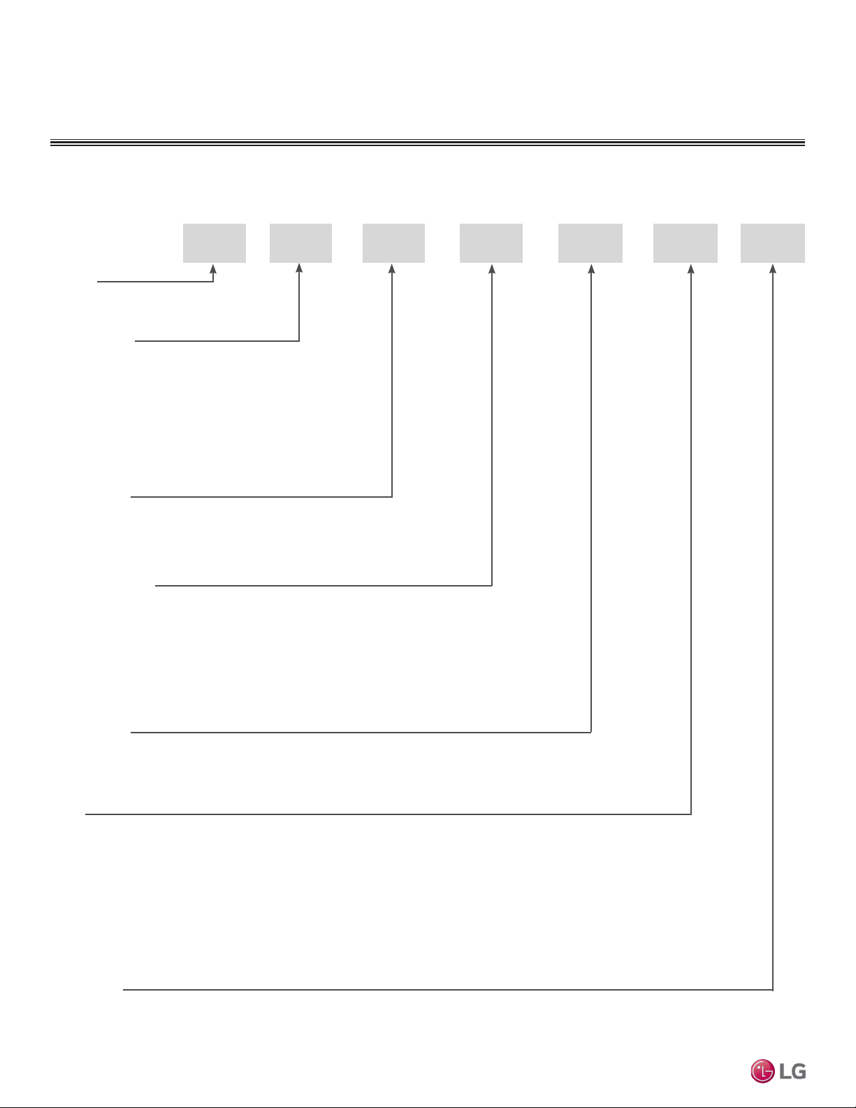
UNIT NOMENCLATURE
V 180 H
System Type:
Style:
SV = High Efficiency Inverter
VP = Gallery
YV = Premier
EV = Mega
V = Standard Inverter
T = Thermostat Compatible
Nominal Capacity
(Nominal cooling capacity in Btu/h):
Frame Type:
A: Art Cool™
S: Standard
C: Four-Way Ceiling-Cassette
D: Ceiling-Concealed Duct (Low Static)
H: Ceiling-Concealed Duct (High Static)
V: Vertical-Horizontal Air Handling
L = LG
18 = 18,000
24 = 24,000
36 = 36,000
42 = 42,000
48 = 48,000
L V 4N
N: Indoor Unit
U: Outdoor Unit
No N or U: System
H = Heat Pump
Generation:
Indoor Units and Outdoor Units
Due to our policy of continuous product innovation, some specications may change without notication.
©LG Electronics U.S.A., Inc., Englewood Cliffs, NJ. All rights reserved. “LG” is a registered trademark of LG Corp.
4 | INTRODUCTION
Single Zone Vertical Air Handling Unit Engineering Manual
LG AIR CONDITIONER
TECHNICAL SOLUTION (LATS)
LG Air Conditioner Technical Solution (LATS) Software
A properly designed and installed refrigerant piping system is critical to the optimal performance of LG air-conditioning systems. To assist
engineers, LG offers, free of charge, LG Air Conditioner Technical Solution (LATS) software—a total design solution for LG air conditioning
systems. Contact your LG Rep for the best software program for your application.
To reduce the risk of designing an improper applied system or one that will not operate correctly, LG requires that LATS software be used on all projects.
Formats
LATS is available to LG customers in three user interfaces: LATS HVAC, LATS CAD2, and LATS Revit. All three LATS formats are available
through www.myLGHVAC.com, or contact an LG Sales Representative.
LATS HVAC is a Windows
®
-based application that aids engineers in designing LG Variable Refrigerant Flow (VRF), Multi F / Multi F MAX,
Single-Zone, and Energy Recovery Ventilator (ERV) systems.
*Windows
®
is a registered mark of Microsoft
®
Corporation.
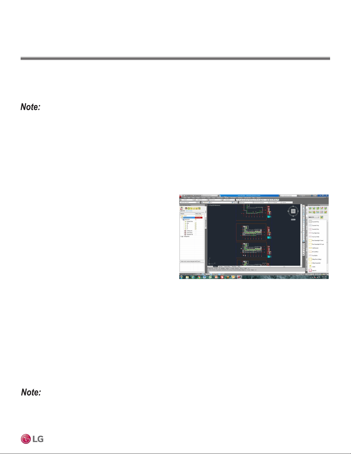
LATS CAD2 combines the LG LATS program with AutoCAD
®
software**. It permits engineers to layout and validate LG Multi V
Variable Refrigerant Flow (VRF), Multi F / Multi F MAX, Single-Zone,
and Energy Recovery Ventilator (ERV) systems directly into CAD
drawings.
LATS Revit integrates the LG LATS program with Revit
®
software**.
It permits engineers to layout and validate Multi V VRF systems
directly into Revit drawings.
**AutoCAD® and Revit® are both registered marks of Autodesk, Inc.
Features
All LG product design criteria have been loaded into the program,
making LATS simple to use: double click or drag and drop the com-
ponent choices. Build systems in Tree Mode where the refrigerant
system can be viewed. Switch to a Schematic diagram to see the
electrical and communications wiring.
LATS software permits the user to input region data, indoor and outdoor design temperatures, modify humidity default values, zoning, specify
type and size of outdoor units and indoor units, and input air flow and external static pressure (ESP) for ducted indoor units.
The program can also:
• Import building loads from a separate Excel file.
• Present options for outdoor unit auto selection.
• Automatically calculate component capacity based on design
conditions for the chosen region.
• Verify if the height differences between the various system
components are within system limits.
• Provide the correct size of each refrigerant piping segment and LG
Y-Branches and Headers.
• Adjust overall piping system length when elbows are added.
• Check for component piping limitations and flag if any parameters
are broken.
• Factor operation and capacity for defrost operation.
• Calculate refrigerant charge, noting any additional trim charge.
• Suggest accessories for indoor units and outdoor units.
• Run system simulation.
Features depend on which LATS program is being used, and the type of system being designed.
Figure 1:Example of LATS CAD2.
Due to our policy of continuous product innovation, some specications may change without notication.
©LG Electronics U.S.A., Inc., Englewood Cliffs, NJ. All rights reserved. “LG” is a registered trademark of LG Corp.
INTRODUCTION | 5
Introduction
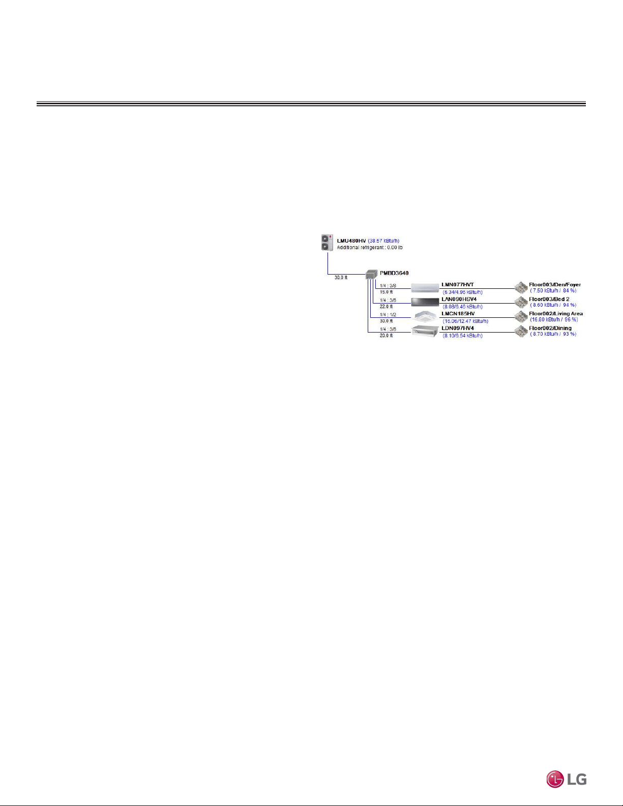
LATS Generates a Complete Project Report
LATS software also generates a report containing project design parameters, cooling and heating design data, system component perfor-
mance, and capacity data. The report includes system combination ratio and refrigerant charge calculations; and provides detailed bill of
material, including outdoor units, indoor units, control devices, accessories, refrigerant pipe sizes segregated by building, by system, by pipe
size, and by pipe segments. LATS can generate an Excel GERP report that can imported into the LG SOPS pricing and ordering system.
Proper Design to Install Procedure
LG encourages a two report design-to-install-procedure. After the
design engineer determines building / zone loads and other details,
the engineer opens the LATS program and inputs the project’s infor-
mation. When the design is complete, the “Auto Piping” and “System
Check” functions must be used to verify piping sizes, limitations, and
if any design errors are present. If errors are found, engineers must
adjust the design, and run Auto Piping and System Check again.
When the design passes the checks, then the engineer prints out
a project “Shop Drawing” (LATS Tree Diagram) and provides it to
the installing contractor. The contractor must follow the LATS Tree
Diagram when building the piping system, but oftentimes the design
changes on the building site:
• Architect has changed location and/or purpose of room(s).
• Outdoor unit cannot be placed where originally intended.
• Structural elements prevent routing the piping as planned.
• Air conditioning system conflicts with other building systems (plumbing, gas lines, etc.).
The contractor must mark any deviation from the design on the Shop Drawing, including as-built straight lines and elbows. This “Mark Up”
drawing must be returned to the design engineer or Rep, who must input contractor changes into the LATS file. (Copy the original LATS soft-
ware file, save and rename as a separate file, and modify all piping lengths by double-clicking on each length and editing information.) Like
the shop drawing, the Auto Piping and System Check must also be run on this new “As Built” drawing. The design engineer or Rep must then
provide the final As Built file to the contractor. The Mark Up version must be compared to the As Built version for the following:
• Differences in pipe diameter(s). If incorrect diameters have been installed, the piping must be changed out. If pipe diameters have changed,
check to see if Y-Branches will also need to be changed.
• Changes to outdoor unit and indoor unit capacities. Capacities changes may impact line length changes.
• Additional refrigerant charge quantity (“Trim Charge”). Trim charge will change if piping lengths and diameters change. The As Built version
must reflect installed piping lengths to ensure correct trim charge.
All documents submitted by the contractor, as well as the Shop Drawing and the As Built Drawing files must be provided for commissioning
purposes. Model and serial numbers for all system components must also be submitted. If the steps previously detailed are not followed, and
all documents are not provided to the LG Commissioner, the project runs the risk of not being commissioned and voiding any limited warranty
LG offers on the equipment.
LG AIR CONDITIONER
TECHNICAL SOLUTION (LATS)
Figure 2:Example of a LATS Tree Diagram.
Due to our policy of continuous product innovation, some specications may change without notication.
©LG Electronics U.S.A., Inc., Englewood Cliffs, NJ. All rights reserved. “LG” is a registered trademark of LG Corp.
6 | INTRODUCTION
Single Zone Vertical Air Handling Unit Engineering Manual

VERTICAL AIR HANDLING
UNIT PRODUCT DATA
“Mechanical Specifications” on page 8
“General Data” on page 10
“Electrical Data” on page 13
“Functions, Controls, and Options”on page 14
“Dimensions” on page 16
“Acoustic Data” on page 20
“Refrigerant Flow Diagrams” on page 31
“Wiring Diagrams” on page 33
“Electrical Connections” on page 38
“External Static Pressure and Airflow Ranges” on page 43
“Accessories” on page 48
Due to our policy of continuous product innovation, some specications may change without notication.
©LG Electronics U.S.A., Inc., Englewood Cliffs, NJ. All rights reserved. “LG” is a registered trademark of LG Corp.
8 | PRODUCT DATA
Single Zone Vertical Air Handling Unit Engineering Manual
MECHANICAL SPECIFICATIONS
Casing
The unit is designed to operate in vertical up flow, down flow (re-
quires conversion kit sold separately), horizontal left, and horizontal
right configurations.
Supply air exits from the top and return air enters from the bottom for
a vertical up flow configuration. Return air opening is from the top for
the vertical down flow configuration. Return air opening is from right
end or left end when in horizontal configuration.
The airflow circulation of the supply air and return air is reversed in
a vertical down flow configuration. Return air plenum sub-base is
to be field provided. Supply air opening has a male flange for duct
connection.
The unit case is made of 22-gauge coated metal and the external
surfaces are finished with a high gloss baked enamel finish. Finish
color is “morning fog” (medium beige). Cold surfaces are galvanized
steel.
The cold surfaces of the case are internally insulated with ½ inch
foil faced, polystyrene fiber insulation. The inside surface of the fan
assembly door access panel is treated with ½ inch polystyrene fiber
insulation, encapsulated on both sides, and sealed along the edges
with a reinforced foil-faced covering to prevent deterioration caused
by panel removal.
All access panels are provided with gasket seals to minimize air
leakage. The unit case is designed to accept an internal, optional,
LG electric strip heater. The unit bears the ETL label. Unit breaker,
fuses, and / or disconnect are provided by others.
Fan Assembly and Control
The indoor unit has an integral fan assembly consisting of a
galvanized steel housing and a forward-curved fan wheel. The direct
drive fan/motor assembly is mounted on rubber grommets isolat-
ing the rotating assembly from the fan housing. The fan motor is a
Brushless Digitally-Controlled design (BLDC), having permanently
lubricated and sealed ball bearings. The fan motor includes thermal,
overcurrent and low RPM protection. The fan/motor assembly is
mounted on vibration attenuating rubber grommets. The fan impel-
ler is statically and dynamically balanced. Fan speed is controlled
using a microprocessor-based direct digital control algorithm that
provides a minimum of a high fan speed in cooling thermal ON and
low fan speed in cooling thermal OFF, high fan speed in heating
thermal ON and fan off in heating thermal OFF. The fan speeds can
be field adjusted between low, medium, and high speeds and DIP
switch settings will allow the fan to run constantly during defrost or
oil return modes. Each setting can be field adjusted from the factory
setting (RPM/ESP). The setting provides delivery of the high speed
air volume against an external static pressure of up to 0.70″ in-wg
(NJ frame - 18k and 24k), and 1.00″ in-wg (NK frame - 36k, 42k, and
48k).
Air Filter
The unit comes with a filter rack sized to
hold a field-
provided 16” x 20” x 1” (NJ frame) or
24” x 20” x 1” (NK frame) filter cartridge.
The filter rack is equipped with guides
that keep the filter centered in the rack.
Filter service access is from the front of
the unit without removing the coil or fan
area access panels. Filter access door is
provided with thumb screws that can be
removed.
Optional Auxiliary Electric Heat
Module(s)
LG optional electric heat modules are de-
signed for field installation in the reheat
position. The electric heat module is
provided with heating elements, contactors, relays, high
temperature safety switch, and interconnecting control wiring
harness with a quick connect plug for easy connection to the air
handling unit control board. Auxiliary heat modules are available in
nominal capacities of 3, 5, 8, 10, 15, and 20 kW. Heating elements
are powered from a field provided separate power source. 3kW
through 10 kW modules are powered from a single power wire.
The 15kW and 20 kW modules are powered from two power wires.
Heating module breakers, fuses, and / or disconnects are to be field
provided.
The optional electric heater when used with the provided simple
controller or a 3rd party thermostat (via dry contact connection),
will have automatic heating operation based on the internal logic. If
manual heater operation is intended, an LG Programmable controller
is required.
Microprocessor Control
The indoor unit is provided with an integrated control panel with
built-in dry contact to communicate with the outdoor unit. All unit op-
eration parameters are stored in non-volatile memory resident on the
unit microprocessor. The microprocessor controls space temperature
through using the value provided by temperature sensors within the
indoor unit. A field-supplied communication cable must be installed to
connect the indoor unit(s) to the outdoor unit.
Figure 3: Vertical Air
Handling Indoor Unit.

Due to our policy of continuous product innovation, some specications may change without notication.
©LG Electronics U.S.A., Inc., Englewood Cliffs, NJ. All rights reserved. “LG” is a registered trademark of LG Corp.
PRODUCT DATA | 9
Product Data
MECHANICAL SPECIFICATIONS
Controls
The indoor unit is supplied with an LG wired controller. Commu-
nication cable from the outdoor unit to the indoor unit must be a
minimum of 18 AWG, four (4) conductor, shielded or unshielded
(if shielded, must be grounded to chassis at ODU only) and must
comply with applicable local and national codes.
Condensate
The unit is designed for gravity draining of condensate.
Condensate Drain Pan
The condensate drain pan is constructed of HIPS (high impact
polystyrene resin).
Coil
The indoor unit coil is constructed with grooved design copper tubes
with slit coil fins, 3 rows, 18 fins per inch.
Controls Features
• Inverter (Variable speed fan)
• Child lock function
• Auto changeover
• Auto restart operation
• Dehumidifying function
• Two thermistor control
• Group control
• External static pressure control
• Self-diagnostics function
• Wired thermostat included
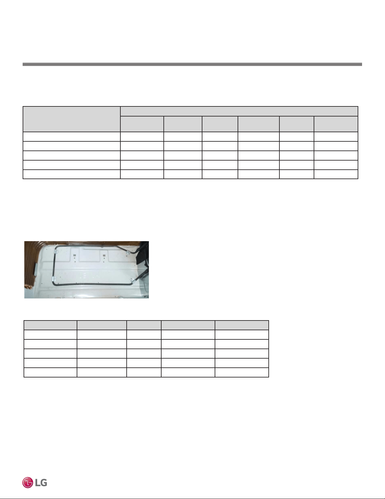
Vertical Down Flow Configuration
NJ and NK frames come factory configured for vertical up flow.
Down flow configuration requires a conversion kit sold separately
(model numbers: PNDFJ0 for NJ frame and PNDFK0 for NK frame).
The kit contains support brackets for the evaporator coil/drain pan
subassembly, addition screws, and a replace front panel to accom-
modate the coil and drain connections for down flow configuration.
Due to our policy of continuous product innovation, some specications may change without notication.
©LG Electronics U.S.A., Inc., Englewood Cliffs, NJ. All rights reserved. “LG” is a registered trademark of LG Corp.
10 | PRODUCT DATA
Single Zone Vertical Air Handling Unit Engineering Manual
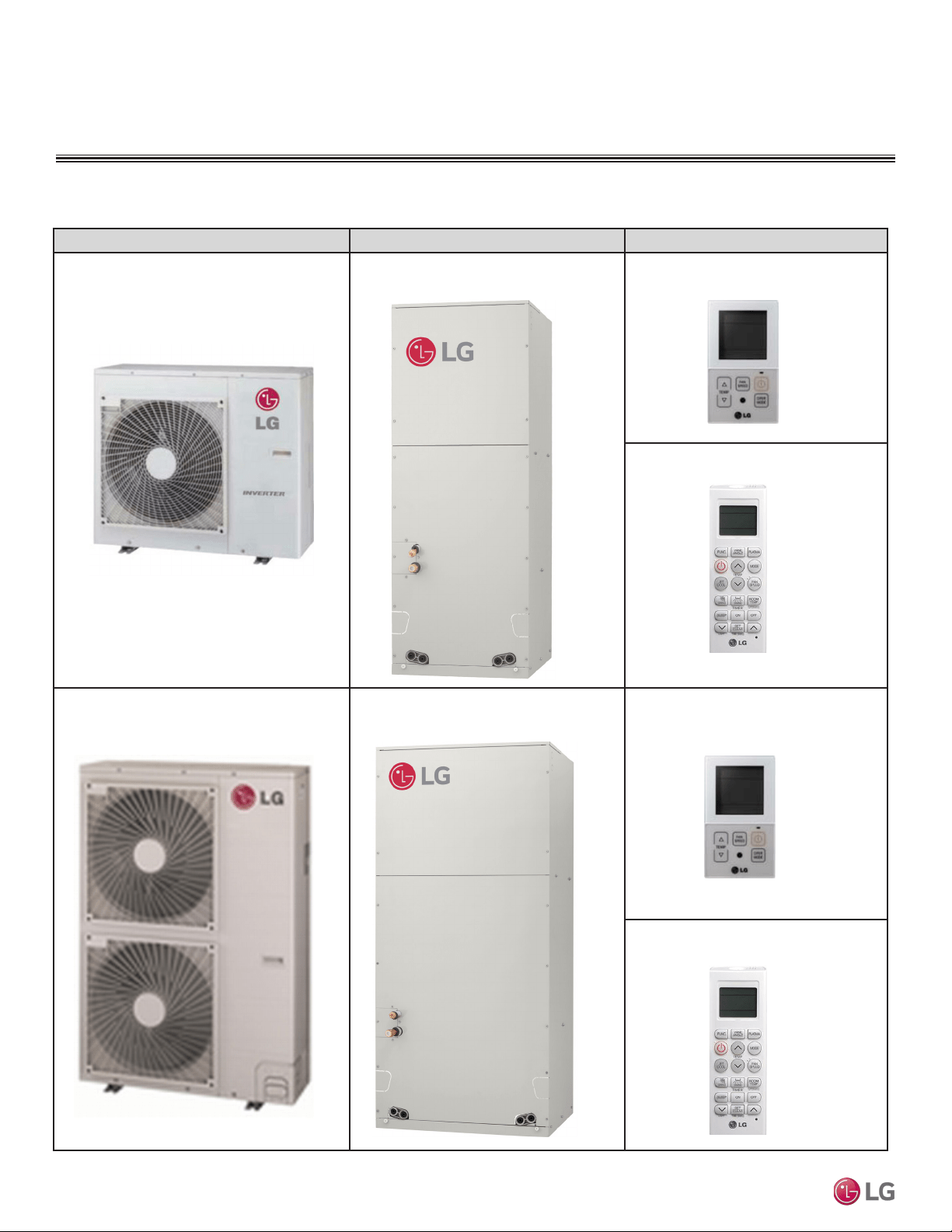
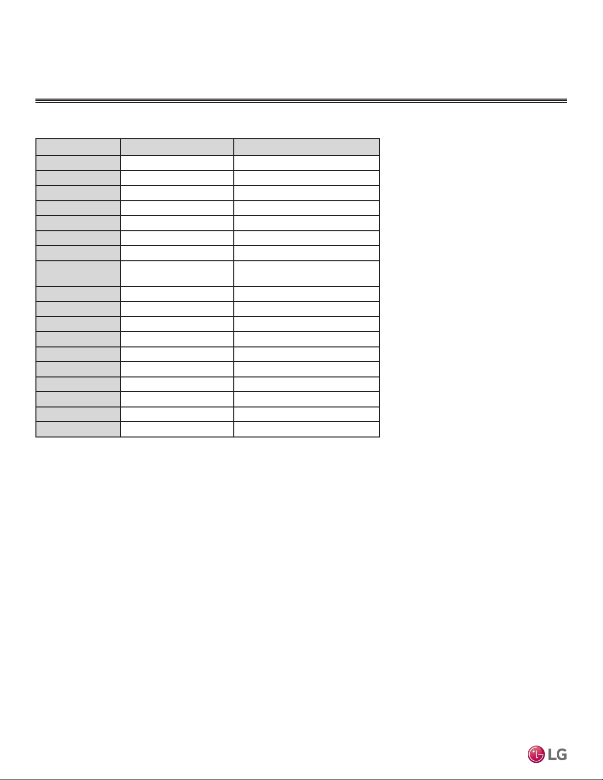
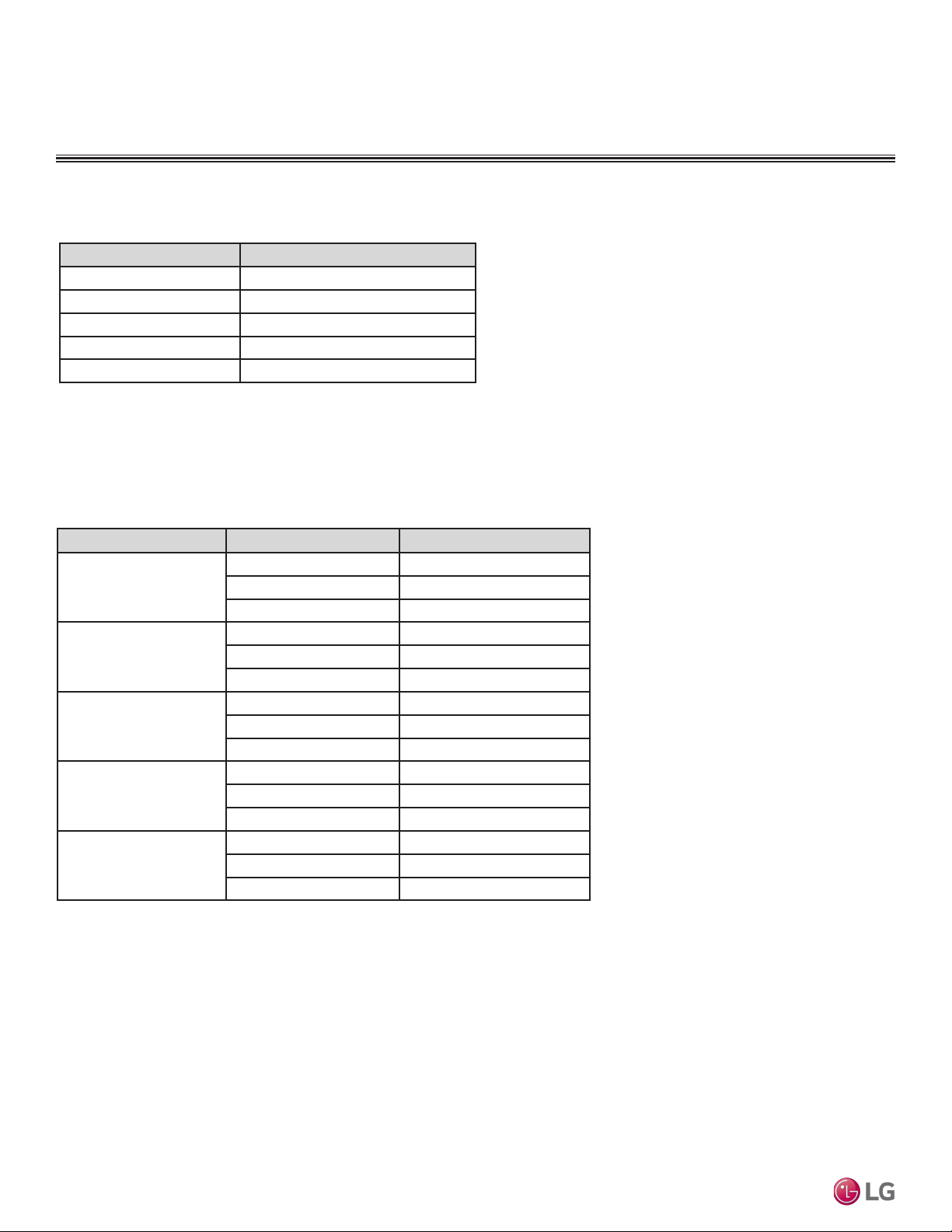
Outdoor Unit Model Indoor Unit Model Remote Controller
LUU188HV
LUU248HV
LVN180HV4, LVN240HV4 (NJ frame) PQRCVCL0QW (LG supplied, wired)
PQWRHQ0FDB (Optional, wireless)
LUU368HV
LUU428HV
LUU488HV
LVN360HV4, LVN420HV, LVN480HV
(NK frame)
PQRCVCL0QW (LG supplied, wired)
PQWRHQ0FDB (Optional, wireless)
GENERAL DATA
Pairing Table
Table 1: Single Zone Vertical Air Handling Unit Pairing Table
Due to our policy of continuous product innovation, some specications may change without notication.
©LG Electronics U.S.A., Inc., Englewood Cliffs, NJ. All rights reserved. “LG” is a registered trademark of LG Corp.
PRODUCT DATA | 11
Product Data
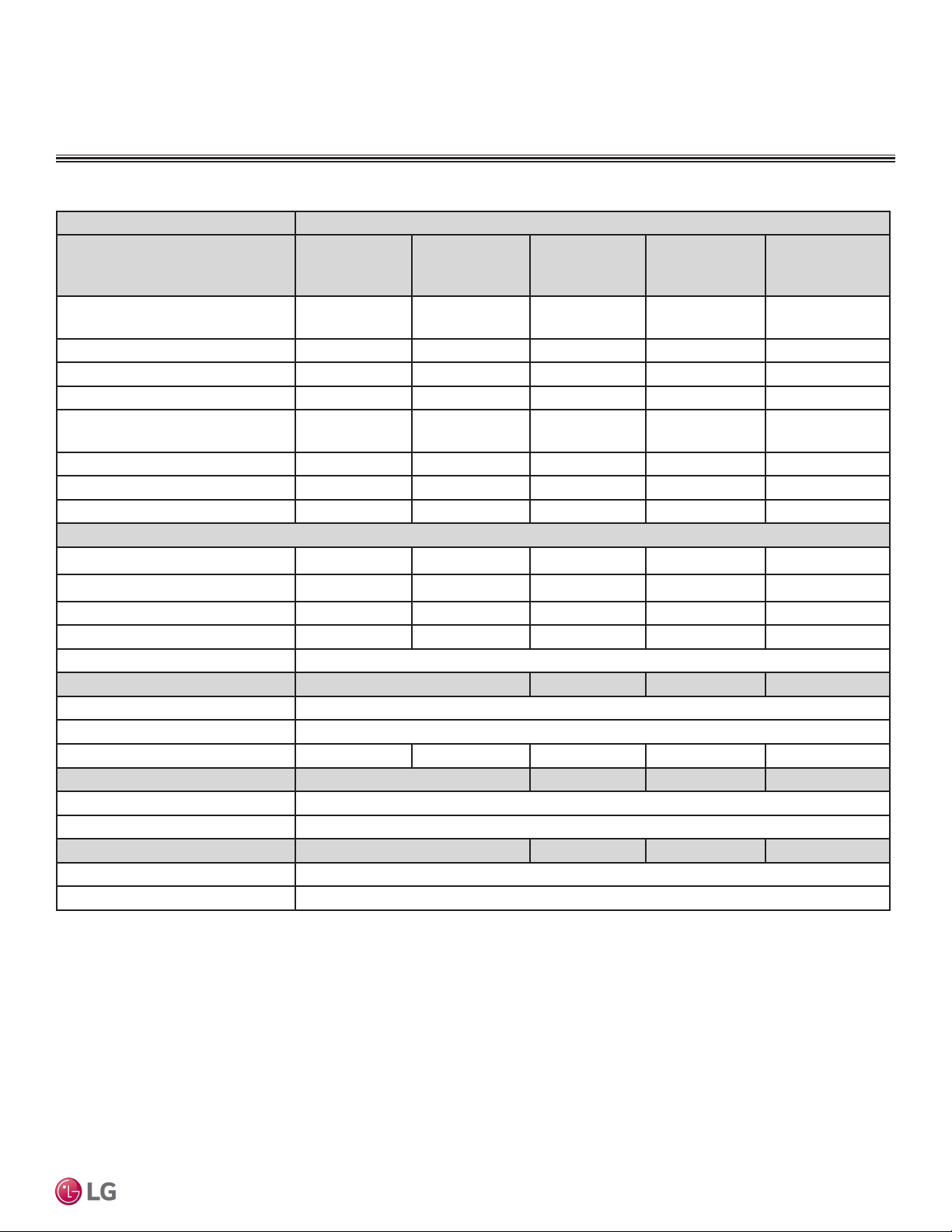
GENERAL DATA / SPECIFICATIONS
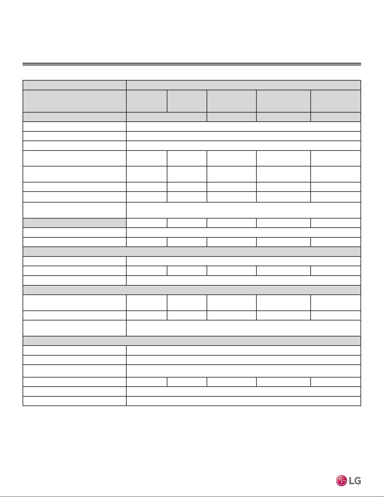
Table 2: Vertical Air Handling Unit General Data.
Type Vertical Air Handling Unit
System (Model) (Indoor Unit / Outdoor
Unit)
LV180HV4
(LVN180HV4/
LUU188HV)
LV240HV4
(LVN240HV4/
LUU248HV)
LV360HV4
(LVN360HV4/
LUU368HV)
LV420HV
(LVN420HV/
LUU428HV)
LV480HV
(LVN480HV/
LUU488HV)
Cooling Capacity (Min/Rated/Max)
(Btu/h)
8,000 ~ 18,000 ~
24,000
9,000 ~ 24,000 ~
28,000
14,000 ~ 36,000 ~
44,000
17,000 ~ 42,000 ~
48,000
18,000 ~ 48,000 ~
53,000
Cooling Power Input
1
(kW) 0.65 ~ 1.35 ~ 2.70 0.70 ~ 1.92 ~ 3.20 1.25 ~ 2.88 ~ 4.80 1.35 ~ 3.80 ~ 5.30 1.40 ~ 4.80 ~ 6.00
EER 13.33 12.50 12.50 11.05 10.00
SEER 19.0 18.0 18.0 17.0 16.5
Heating Capacity (Min/Rated/Max)
(Btu/h)
9,000 ~ 20,000 ~
23,000
10,000 ~ 27,000 ~
30,000
15,000 ~ 40,000 ~
47,000
18,000 ~ 47,000 ~
55,000
19,000 ~ 56,000 ~
60,000
Heating Power Input
1
(kW) 0.65 ~ 1.60 ~ 2.10 0.75 ~ 2.26 ~ 2.80 1.35 ~ 3.39 ~ 5.05 1.45 ~ 4.00 ~ 5.65 1.50 ~ 5.10 ~ 6.20
COP 3.66 3.50 3.46 3.44 3.22
HSPF 9.5 10.0 10.0 10.0 9.5
Maximum Heating Capacity (Btu/h)
Outdoor 17°F) (WB)/Indoor 70°F (DB) 18,000 22,000 32,000 37,000 40,000
Outdoor 5°F(WB)/Indoor 70°F (DB) 16,000 20,000 30,000 32,000 34,000
Power Input [W] @ Outdoor 5°F (WB) 2,500 3,200 4,400 4,800 5,250
Outdoor -4 °F(WB)/Indoor 70°F (DB) 11,000 15,000 22,000 24,000 26,000
Power Supply V, Ø, Hz 208-230 / 1 / 60
Outdoor Unit Operating Range
Cooling (°F DB) 5 - 118
Optional Wind Bafe Cooling (°F DB) Yes (-4)
Heating (°F WB) -4 - 64 -4 - 64 -4 - 64 -4 - 64 -4 - 64
Indoor Unit Operating Range
Cooling (°F WB) 57 - 77
Heating (°F DB) 59 - 81
Indoor Temperature Setting Range
Cooling (°F DB) 65 - 86
Heating (°F WB) 61 - 86
EEV: Electronic Expansion Valve, IDU: Indoor Unit, ODU: Outdoor Unit. This unit comes
with a dry helium charge.
This data is rated 0 ft above sea level, with 24.6 ft of refrigerant line per indoor unit and a 0
ft level difference between outdoor and indoor units.
Cooling capacity rating obtained with air entering the indoor coil at 80ºF dry bulb (DB) and
67ºF wet bulb (WB); and outdoor ambient conditions of 95ºF dry bulb (DB) and 75ºF wet
bulb (WB).
Heating capacity rating obtained with air entering the indoor unit at 70ºF dry bulb (DB) and
60ºF wet bulb (WB); and outdoor ambient conditions of 47ºF dry bulb (DB) and 43ºF wet
bulb (WB).
1 Power Input is rated at high speed.
2 All communication / connection (power) cable from the outdoor unit to the indoor unit
are field supplied and is to be a minimum four-conductor, 18 AWG, stranded, shielded or
unshielded (if shielded, it must be grounded to the chassis of ODU only), and must comply
with applicable local and national codes.
3 Take appropriate actions at the end of HVAC equipment life to recover, recycle, reclaim or
destroy R410A refrigerant according to applicable regulations (40 CFR Part 82, Subpart F)
under section 608 of CAA.
4 Sound pressure levels are tested in an anechoic chamber under ISO Standard 3745 and
are the same in both cooling and heating mode. These values can increase due to ambient
conditions during operation.
5 Piping lengths are equivalent.
Due to our policy of continuous product innovation, some specications may change without notication.
©LG Electronics U.S.A., Inc., Englewood Cliffs, NJ. All rights reserved. “LG” is a registered trademark of LG Corp.
12 | PRODUCT DATA
Single Zone Vertical Air Handling Unit Engineering Manual
Table 3: Vertical Air Handling Unit General Data, continued.
Type Vertical Air Handling Unit
System (Model) (Indoor Unit / Outdoor
Unit)
LV180HV4
(LVN180HV4/
LUU188HV)
LV240HV4
(LVN240HV4/
LUU248HV)
LV360HV4
(LVN360HV4/
LUU368HV)
LV420HV
(LVN420HV/
LUU428HV)
LV480HV
(LVN480HV/
LUU488HV)
Unit Data
Refrigerant Type
3
R410A
Additional Refrigerant Charge (oz./ft.) 0.43
Refrigerant Control EEV
Indoor Unit Sound Pressure Level (dB(A))
(H/M/L)
4
42 / 42 / 41 43 / 42 / 41 45 / 44 / 43 48 / 45 / 44 49 / 48 / 44
Outdoor Unit Sound Pressure Level
(dB(A)) (Cool/Heat)
4
48 / 52 48 / 52 52 / 54 52 / 54 52 / 54
Indoor Unit Net / Shipping Weight (lbs.) 129 / 140 129 / 140 165 / 188 165 / 188 165 / 188
Outdoor Unit Net / Shipping Weight (lbs.) 129 / 141 129 / 141 203 / 232 203 / 232 203 / 232
Power Wiring / Communications Cable
(No. x AWG)
2
4 x 18
Power Supply (No. x AWG) 3 x 12 3 x 12 3 x 10 3 x 10 3 x 10
Compressor (Type x Qty.) Twin Rotary x 1
Dehumidication Rate (pts./hr.) 2 2.5 3.4 4.3 5.2
Fan
Indoor Unit Type x Qty. Sirocco x 1
Outdoor Unit Type x Qty. Propeller x 1 Propeller x 1 Propeller x 2 Propeller x 2 Propeller x 2
Motor / Drive Brushless Digitally Controller / Direct
Airflow Rate
Indoor Unit (H / M / L [CFM]) 640 / 580 / 480 710 / 640 / 480 1,100 / 1,000 / 900 1,260 / 1,100 / 1,000 1,400 / 1,260 /
1,000
Outdoor Unit (CFM) 2,048 2,048 1,942 x 2 1,942 x 2 1,942 x 2
Factory Set (High) External Static Pressure
(in.wg)
0.3
Piping
Liquid (in.) 3/8
Vapor (in.) 5/8
Indoor Unit Condensate Drain I.D. (in.) Primary & Secondary: 3/4 FPT
Minimum / Maximum Pipe Length (ft.)
5
6.6 / 164 6.6 / 164 6.6 / 246 6.6 / 246 6.6 / 246
Piping Length (no additional refrigerant, ft.) 24.6
Maximum Elevation Difference (ft.) 98.4
EEV: Electronic Expansion Valve, IDU: Indoor Unit, ODU: Outdoor Unit. This unit comes with a
dry helium charge.
This data is rated 0 ft above sea level, with 24.6 ft of refrigerant line per indoor unit and a 0 ft
level difference between outdoor and indoor units.
Cooling capacity rating obtained with air entering the indoor coil at 80ºF dry bulb (DB) and 67ºF
wet bulb (WB); and outdoor ambient conditions of 95ºF dry bulb (DB) and 75ºF wet bulb (WB).
Heating capacity rating obtained with air entering the indoor unit at 70ºF dry bulb (DB) and 60ºF
wet bulb (WB); and outdoor ambient conditions of 47ºF dry bulb (DB) and 43ºF wet bulb (WB).
1
Power Input is rated at high speed.
2 All communication / connection (power) cable from the outdoor unit to the indoor unit
are field supplied and is to be a minimum four-conductor, 18 AWG, stranded, shielded or
unshielded (if shielded, it must be grounded to the chassis of ODU only), and must comply
with applicable local and national codes.
3 Take appropriate actions at the end of HVAC equipment life to recover, recycle, reclaim or
destroy R410A refrigerant according to applicable regulations (40 CFR Part 82, Subpart F) under
section 608 of CAA.
4 Sound pressure levels are tested in an anechoic chamber under ISO Standard 3745 and
are the same in both cooling and heating mode. These values can increase due to ambient
conditions during operation.
5 Piping lengths are equivalent.
GENERAL DATA / SPECIFICATIONS
Due to our policy of continuous product innovation, some specications may change without notication.
©LG Electronics U.S.A., Inc., Englewood Cliffs, NJ. All rights reserved. “LG” is a registered trademark of LG Corp.
PRODUCT DATA | 13
Product Data
Voltage tolerance is ±10%.
Maximum allowable voltage unbalance is 2%.
RLA = Rated Load Amps.
MCA = Minimum Circuit Ampacity.
Maximum Overcurrent Protection (MOP) is calculated as follows:
(Largest motor FLA x 2.25) + (Sum of other motor FLA) rounded
down to the nearest standard fuse size.
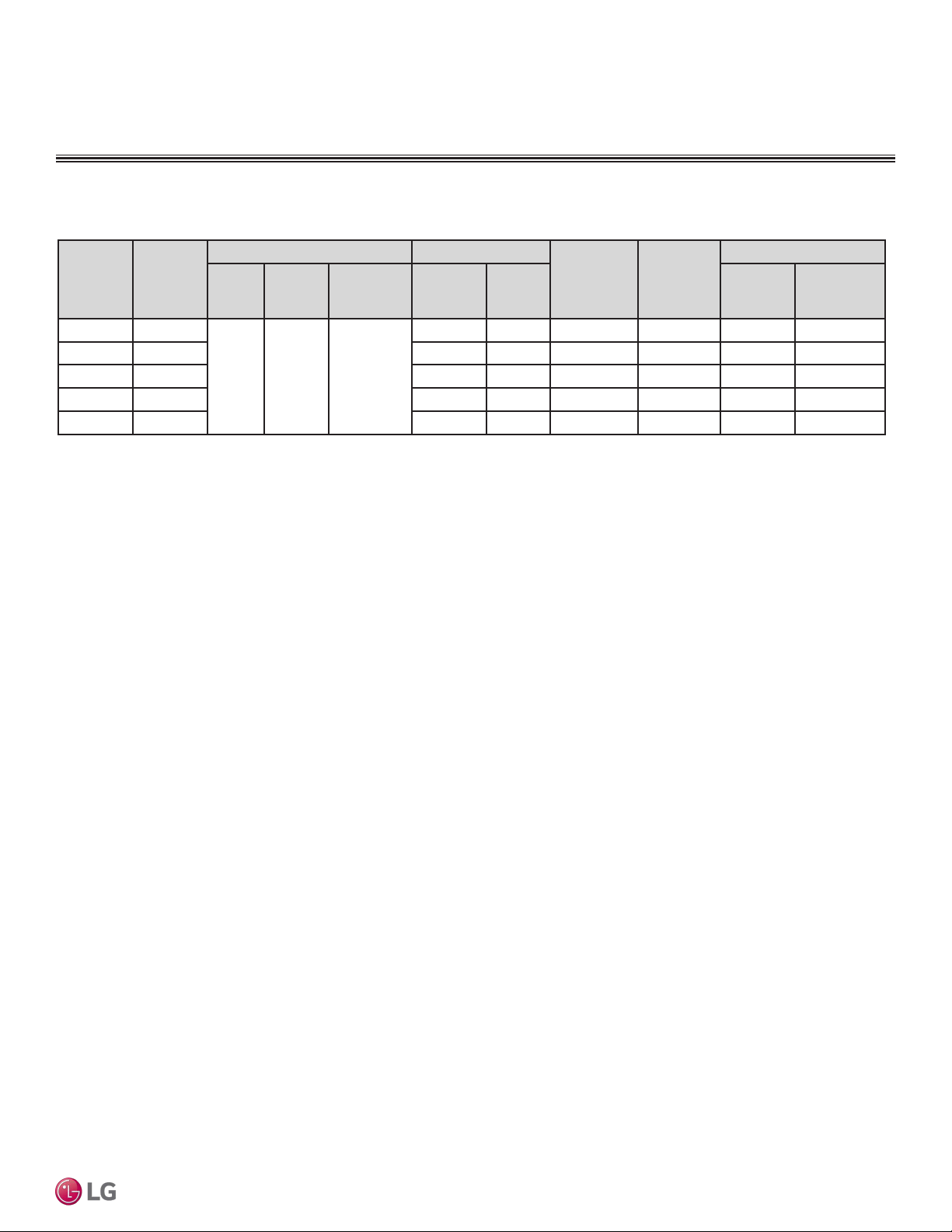
Table 4: Vertical Air Handling Unit ODU Electrical Data.
Electrical Data
ELECTRICAL DATA
Nominal
Tons
Model
Name
Unit Power Supply Compressor
Quantity
Compressor
Motor RLA
(Cooling)
Condenser Fan Motor(s)
Hz Volts Voltage
Range
MCA MOP Condenser
Fan Quan-
tity.
Condenser
Fan
Motor FLA
1.5 LUU188HV 60 208/230 Min.: 187
Max.: 253
20 30 1 13.5 1 1.6
2.0 LUU248HV 20 30 1 13.5 1 1.6
3.0 LUU368HV 32 40 1 21.0 2 1.6 x 2
3.5 LUU428HV 32 40 1 21.0 2 1.6 x 2
4.0 LUU488HV 32 40 1 21.0 2 1.6 x 2
Due to our policy of continuous product innovation, some specications may change without notication.
©LG Electronics U.S.A., Inc., Englewood Cliffs, NJ. All rights reserved. “LG” is a registered trademark of LG Corp.
14 | PRODUCT DATA
Single Zone Vertical Air Handling Unit Engineering Manual
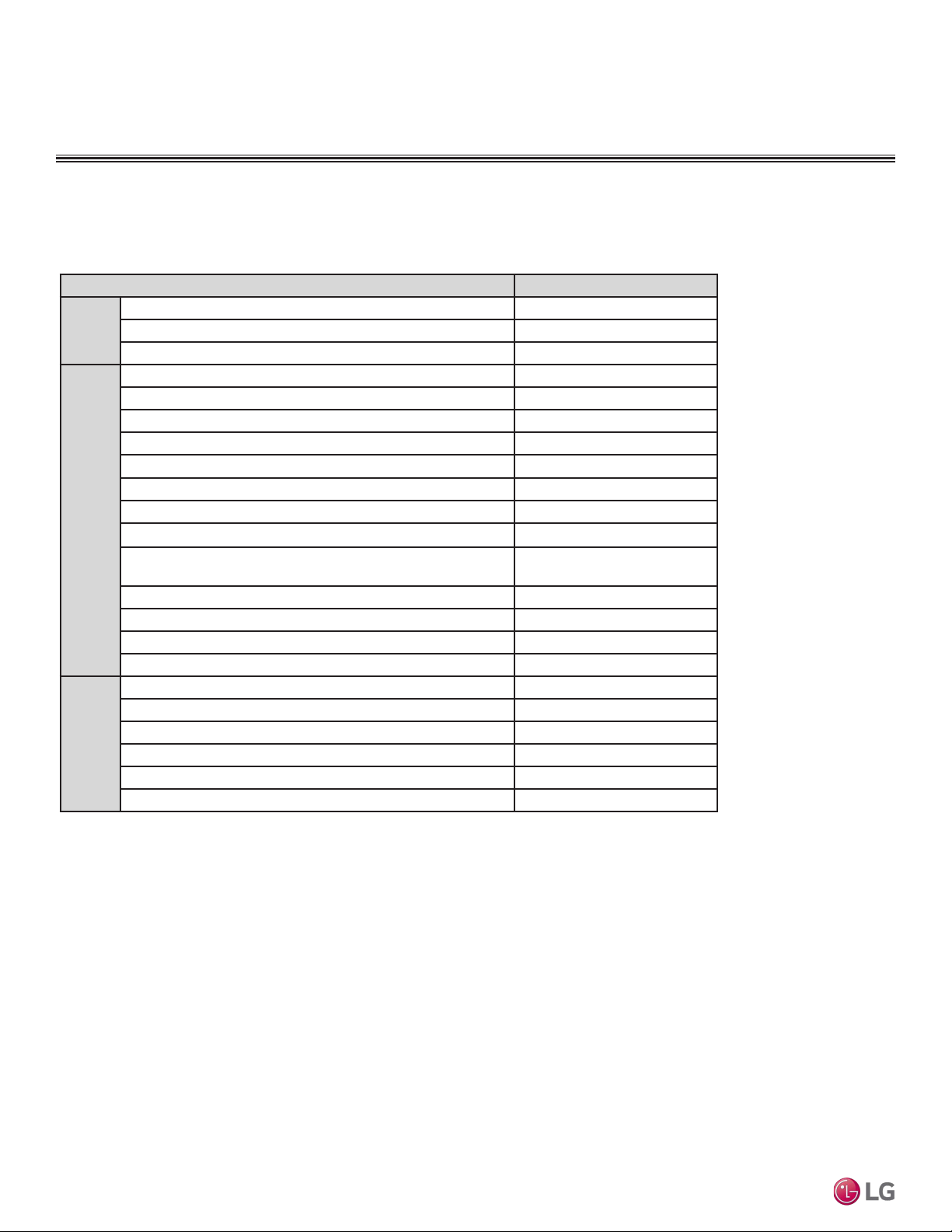
Table 5: Indoor Unit—Functions, Controls and Options.
1
Primary washable filters.
2
Requires wired zone controller.
√ = Standard feature
o = Unit option
X = Not Available
* = Group Control can limit functions and features
Indoor Unit Type Vertical Air Handling Unit
Airow
Air Supply Outlet 1
Airflow steps (fan/cool/heat) 3/3/3
Washable anti-fungal
1
X
Operation
Drain pump X
E.S.P Control √
Hot Start √
Self diagnostics √
Soft Dry (dehumidification) √
Auto changeover √
Auto restart √
Child lock o
Group control – Requires the use of one Group Control Cable
Kit* (PZCWRCG3) for every additional indoor unit
o
Sleep mode √
Timer (on/off) √
Weekly schedule √
Two thermistor control o
Controllers
7-Day programmable controller o
Simple wired remote controller √
Wireless LCD remote control o
2
Dry contact √
Dry contact (temperature setting) X
Central control (LGAP) √
Functions, Controls, and Options for LVN180HV4, LVN240HV4, LVN360HV4,
LVN420HV, LVN480HV
FUNCTIONS, CONTROLS, AND OPTIONS
Indoor Unit
Due to our policy of continuous product innovation, some specications may change without notication.
©LG Electronics U.S.A., Inc., Englewood Cliffs, NJ. All rights reserved. “LG” is a registered trademark of LG Corp.
PRODUCT DATA | 15
Product Data
Functions, Controls, and Options for LUU188HV, LUU248HV, LUU368HV,
LUU428HV, LUU488HV
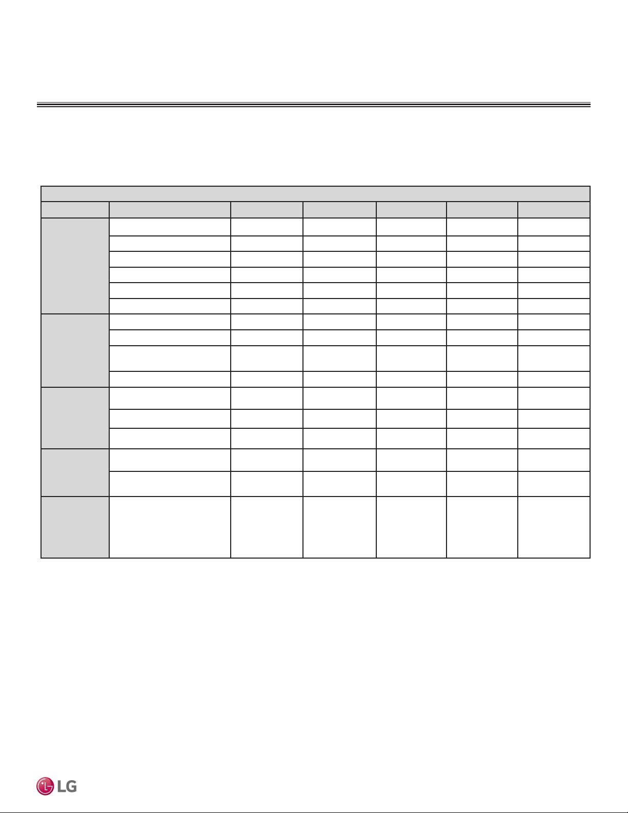
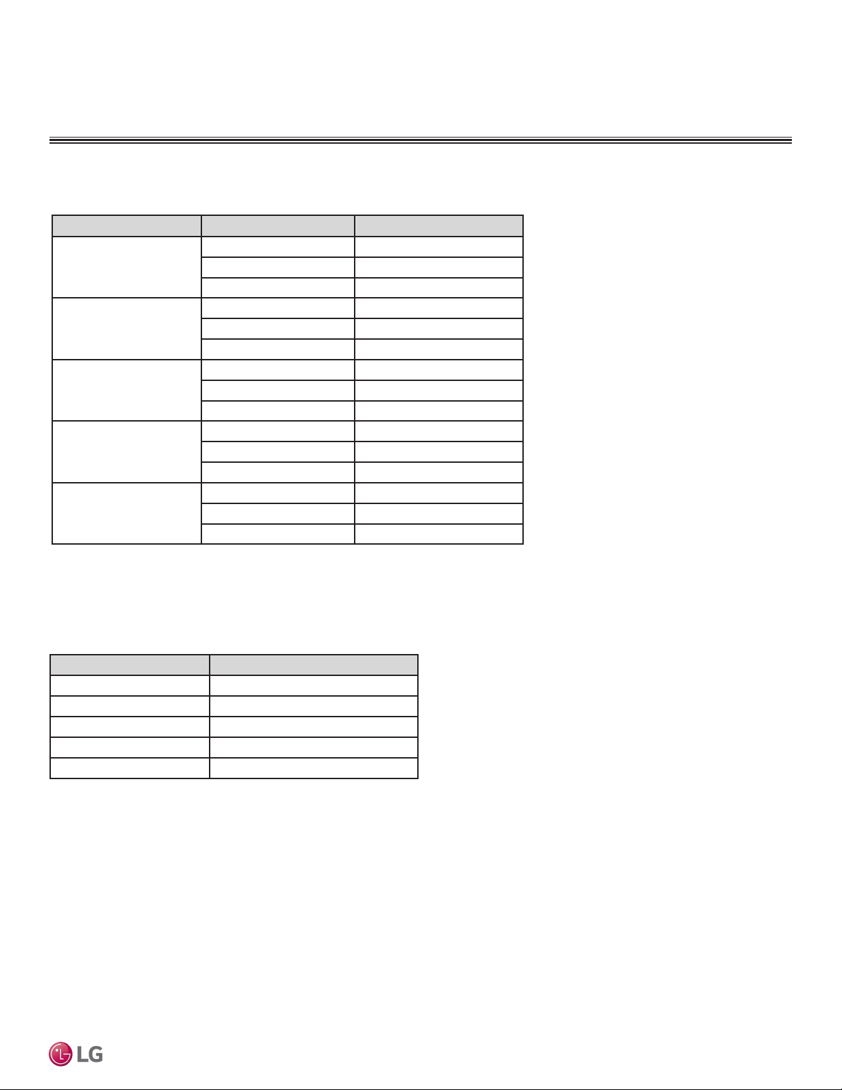
Table 6: Outdoor Unit—Functions, Controls and Options.
Outdoor Unit
Category Functions LUU188HV LUU248HV LUU368HV LUU428HV LUU488HV
Reliability
Defrost / Deicing O O O O O
High pressure sensor O O O O O
Phase protection X X X X X
Restart delay (3-minutes) O O O O O
Self diagnosis O O O O O
Soft start O O O O O
Convenience
Night Quiet Operation O O O O O
Mode Lock O O O O O
Pump Down (Forced Cooling
Operation)
O O O O O
Network solution (LGAP) O O O O O
Central
Controller
AC Smart IV PACS4B000 PACS4B000 PACS4B000 PACS4B000 PACS4B000
ACP IV PACP4B000 PACP4B000 PACP4B000 PACP4B000 PACP4B000
PI485 PMNFP14A1 PMNFP14A1 PMNFP14A1 PMNFP14A1 PMNFP14A1
Remote
Controller
MultiSITE CRC1 PREMTBVC0 PREMTBVC0 PREMTBVC0 PREMTBVC0 PREMTBVC0
MultiSITE CRC1+ PREMTBVC1 PREMTBVC1 PREMTBVC1 PREMTBVC1 PREMTBVC1
Integration
Solution
MultiSITE
Communications Manager
PBACNBTR0A PBACNBTR0A PBACNBTR0A PBACNBTR0A PBACNBTR0A
FUNCTIONS, CONTROLS, AND OPTIONS
Outdoor Unit
√ = Standard feature
o = Unit option
X = Not Available
Due to our policy of continuous product innovation, some specications may change without notication.
©LG Electronics U.S.A., Inc., Englewood Cliffs, NJ. All rights reserved. “LG” is a registered trademark of LG Corp.
16 | PRODUCT DATA
Single Zone Vertical Air Handling Unit Engineering Manual
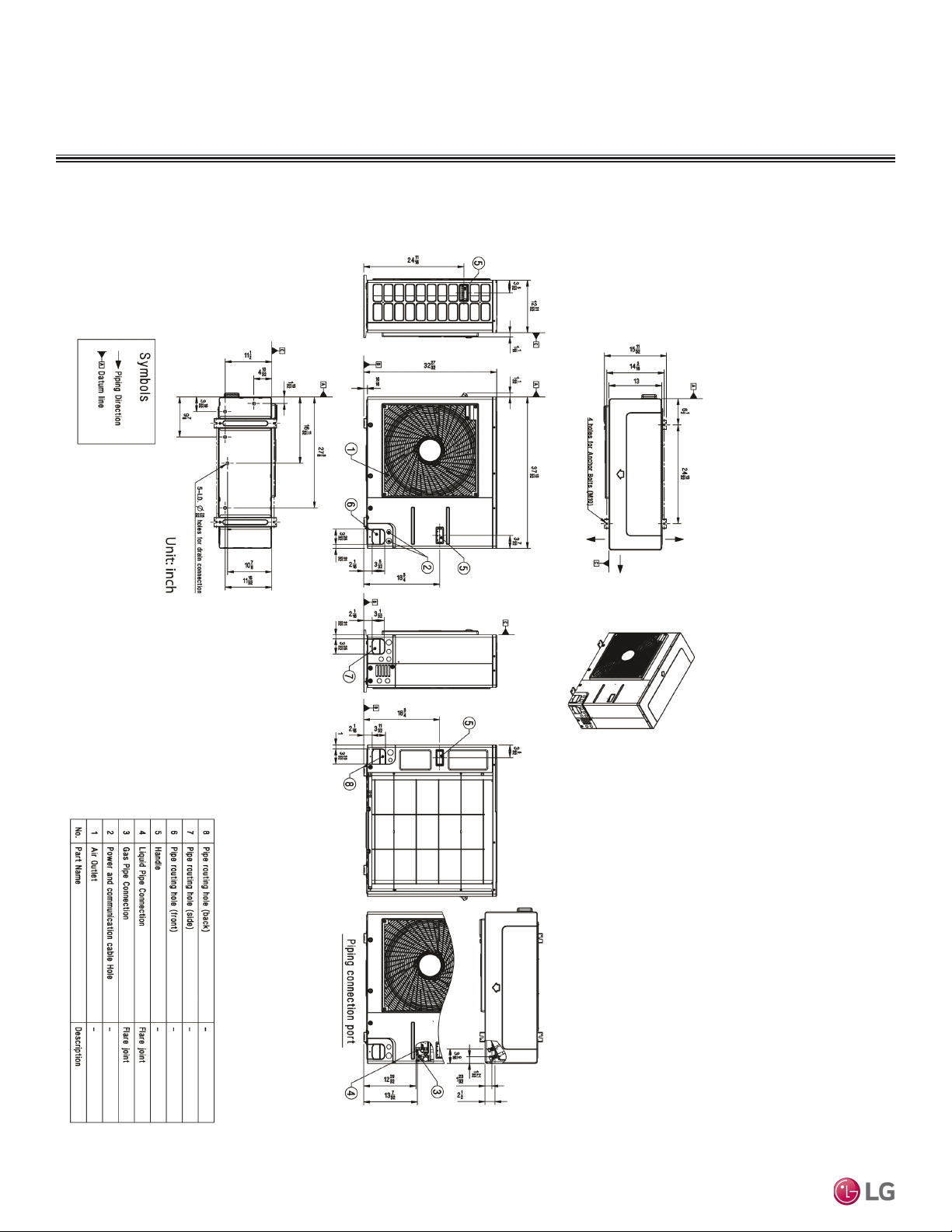
OUTDOOR UNIT DIMENSIONS
Dimensions for LUU188HV, LUU248HV
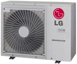
Figure 4: LUU188HV, LUU248HV Unit Dimensions.
LUU188HV, LUU248HV
Due to our policy of continuous product innovation, some specications may change without notication.
©LG Electronics U.S.A., Inc., Englewood Cliffs, NJ. All rights reserved. “LG” is a registered trademark of LG Corp.
PRODUCT DATA | 17
Product Data
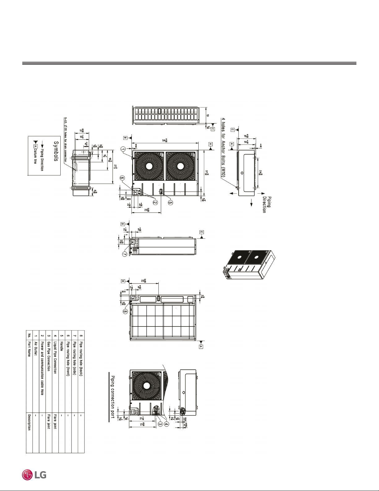
OUTDOOR UNIT DIMENSIONS
Dimensions for LUU368HV, LUU428HV, LUU488HV
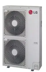
Figure 5: LUU368HV, LUU428HV, LUU488HV Unit Dimensions.
LUU368HV, LUU428HV, LUU488HV
Due to our policy of continuous product innovation, some specications may change without notication.
©LG Electronics U.S.A., Inc., Englewood Cliffs, NJ. All rights reserved. “LG” is a registered trademark of LG Corp.
18 | PRODUCT DATA
Single Zone Vertical Air Handling Unit Engineering Manual
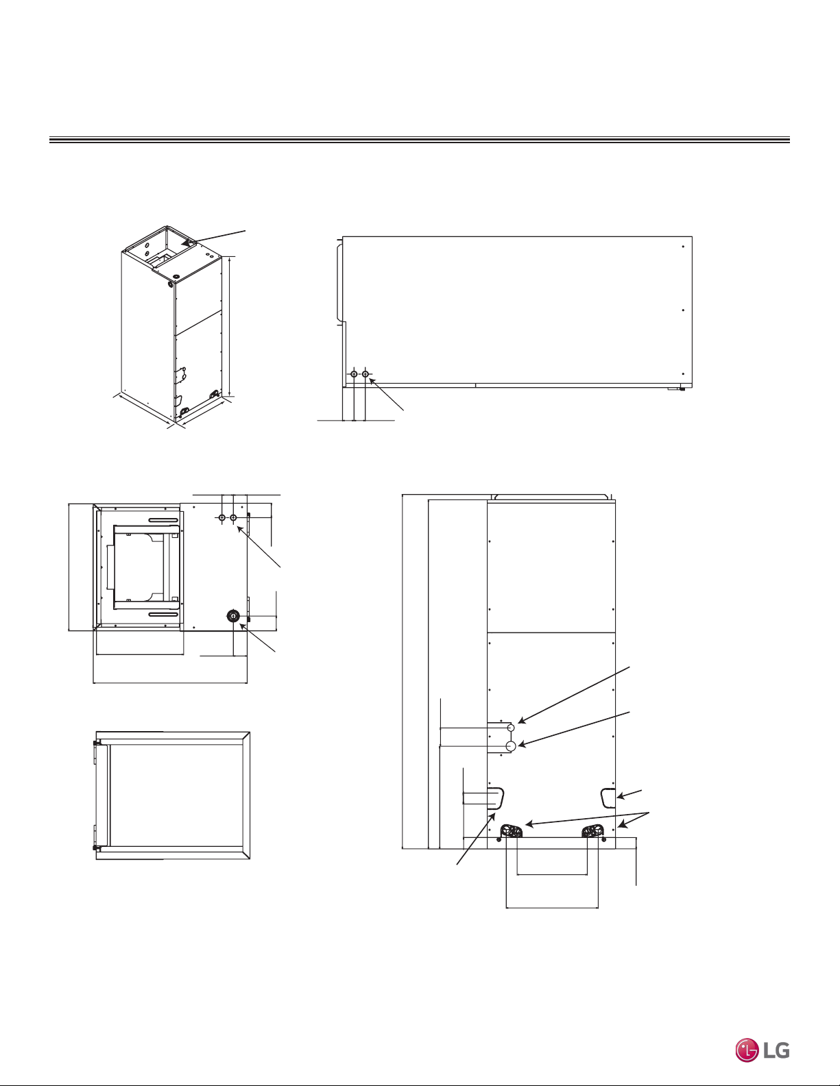
INDOOR UNIT DIMENSIONS
Figure 6: LVN180HV4, LVN240HV4 Indoor Unit Dimensions.
LVN180HV4, LVN240HV4
Dimensions for LVN180HV4, LVN240HV4 (NJ frame)
48-11/16
18
21-1/4
48-11/16
49-5/16
2-9/16
1-15/16
21-1/4
12-1/8
1-1/2
9-15/16
2-1/16
18
17
2-1/8
13
4-11/16
1-9/16
1-9/16
1-9/16 1-15/16
1-5/8
14-5/16
Unit: inches
Note: All measurements
have a tolerance of ±1/4 in.
Drain connection
for horizontal right
application
Drain connection
for horizontal left
application
Liquid pipe
Vapor pipe
7/8” Wiring
knockouts
7/8” Wiring
knockouts
1-11/16” Wiring
knockouts
Supply Air
opening
Return Air
opening
BOTTOM VIEW
TOP VIEW
SIDE VIEW
FRONT VIEW
Due to our policy of continuous product innovation, some specications may change without notication.
©LG Electronics U.S.A., Inc., Englewood Cliffs, NJ. All rights reserved. “LG” is a registered trademark of LG Corp.
PRODUCT DATA | 19
Product Data
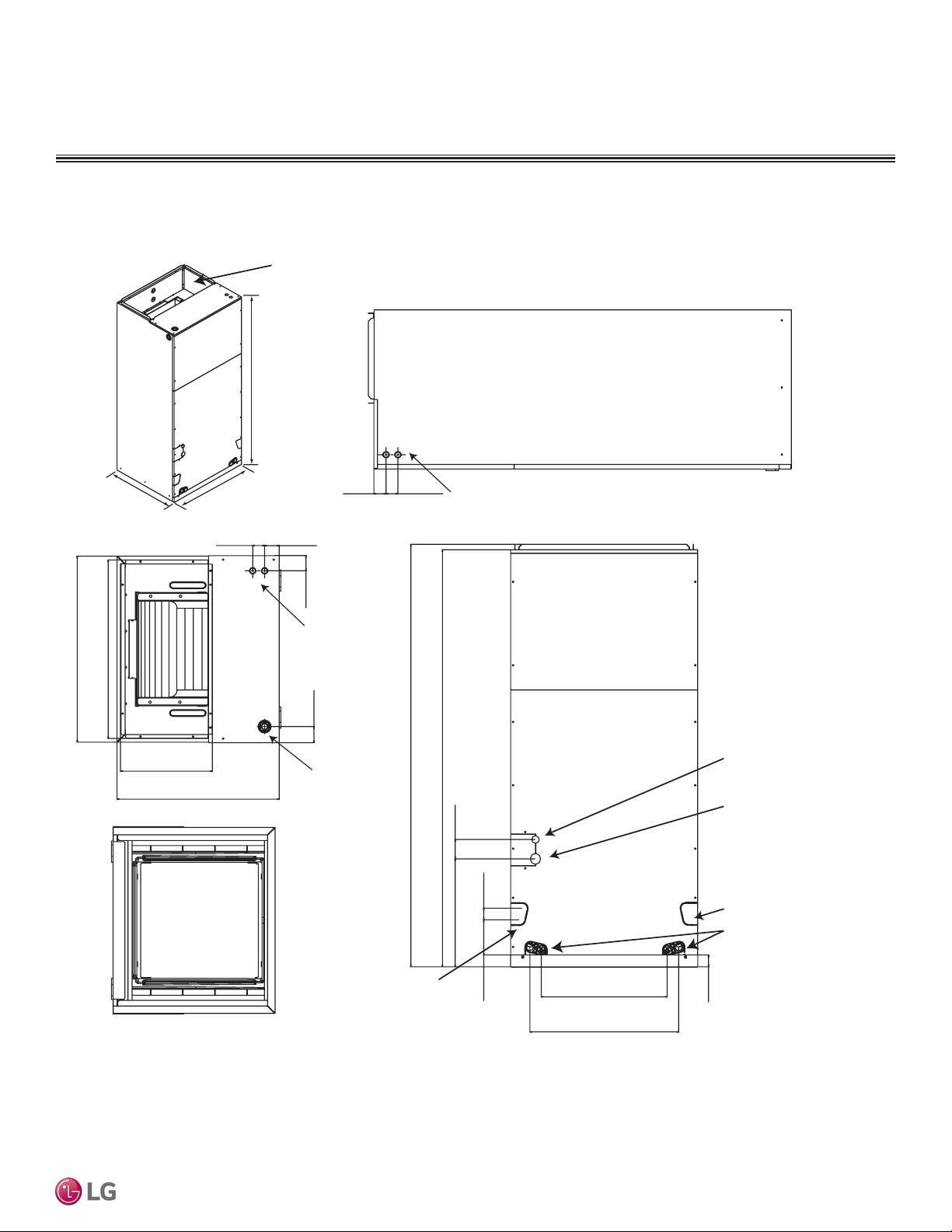
INDOOR UNIT DIMENSIONS
LVN360HV4, LVN420HV, LVN480HV
Figure 7: LVN360HV4, LVN420HV, LVN480HV Indoor Unit Dimensions.
Dimensions for LVN360HV4, LVN420HV, LVN480HV (NK frame)
55-3/16
25
21-1/4
55-3/16
55-13/16
2-9/16
21-1/4
12-1/8
1-1/2
16-15/16
2-1/16
25
24
2-3/16
20
4-11/16
1-9/16
1-9/16
1-9/16
1-15/16
1-5/8
14-1/4
Unit: inches
Note: All measurements
have a tolerance of ±1/4 in.
Supply Air
opening
7/8” Wiring
knockouts
SIDE VIEW
7/8” Wiring
knockouts
1-11/16” Wiring
knockouts
Return Air
opening
FRONT VIEW
Liquid pipe
Vapor pipe
Drain connection
for horizontal left
application
Drain connection
for upflow application
Drain connection
for horizontal right
application
Due to our policy of continuous product innovation, some specications may change without notication.
©LG Electronics U.S.A., Inc., Englewood Cliffs, NJ. All rights reserved. “LG” is a registered trademark of LG Corp.
20 | PRODUCT DATA
Single Zone Vertical Air Handling Unit Engineering Manual
ACOUSTIC DATA
Indoor Units
• Measurements are taken 3.3 ft away from the front of the unit.
• Sound pressure levels are measured in dB(A) with a tolerance of ±3.
• Sound pressure levels are tested in an anechoic chamber under ISO
Standard 3745.
Operating Conditions:
• Power source: 220V/60 Hz
• Sound level will vary depending on a range of factors including the
construction (acoustic absorption coefficient) of a particular room in
which the unit was installed.
3.3ft
3.3ft
Microphone
Figure 8: Sound Pressure Measurement Location.
Table 7: Vertical Air Handling Unit Indoor Unit Sound Pressure Levels.
Model Sound Pressure Levels dB(A)
High Fan Speed Medium Fan Speed Low Fan Speed
NJ Frames
LVN180HV4 42 42 41
LVN240HV4 43 42 41
NK Frames
LVN360HV4 45 44 43
LVN420HV 48 45 44
LVN480HV 49 48 44
Indoor Unit Sound Pressure Levels
Indoor Unit Sound Pressure Measurement
Due to our policy of continuous product innovation, some specications may change without notication.
©LG Electronics U.S.A., Inc., Englewood Cliffs, NJ. All rights reserved. “LG” is a registered trademark of LG Corp.
PRODUCT DATA | 21
Product Data
LVN180HV4 LVN240HV4
Figure 9: LVN180HV4 and LVN240HV4 Sound Pressure Level Diagrams.
LVN180HV4, LVN240HV4 Sound Pressure Diagrams
ACOUSTIC DATA
Indoor Units
Due to our policy of continuous product innovation, some specications may change without notication.
©LG Electronics U.S.A., Inc., Englewood Cliffs, NJ. All rights reserved. “LG” is a registered trademark of LG Corp.
22 | PRODUCT DATA
Single Zone Vertical Air Handling Unit Engineering Manual
LVN360HV4, LVN420HV Sound Pressure Diagrams
LVN360HV4 LVN420HV
Figure 10: LVN360HV4 and LVN420HV Sound Pressure Level Diagrams.
ACOUSTIC DATA
Indoor Units
Due to our policy of continuous product innovation, some specications may change without notication.
©LG Electronics U.S.A., Inc., Englewood Cliffs, NJ. All rights reserved. “LG” is a registered trademark of LG Corp.
PRODUCT DATA | 23
Product Data
INDOOR ACOUSTIC DATA
Indoor Units
LVN480HV Sound Pressure Diagrams
Figure 11: LVN480HV Sound Pressure Level Diagrams.
LVN480HV
Due to our policy of continuous product innovation, some specications may change without notication.
©LG Electronics U.S.A., Inc., Englewood Cliffs, NJ. All rights reserved. “LG” is a registered trademark of LG Corp.
24 | PRODUCT DATA
Single Zone Vertical Air Handling Unit Engineering Manual
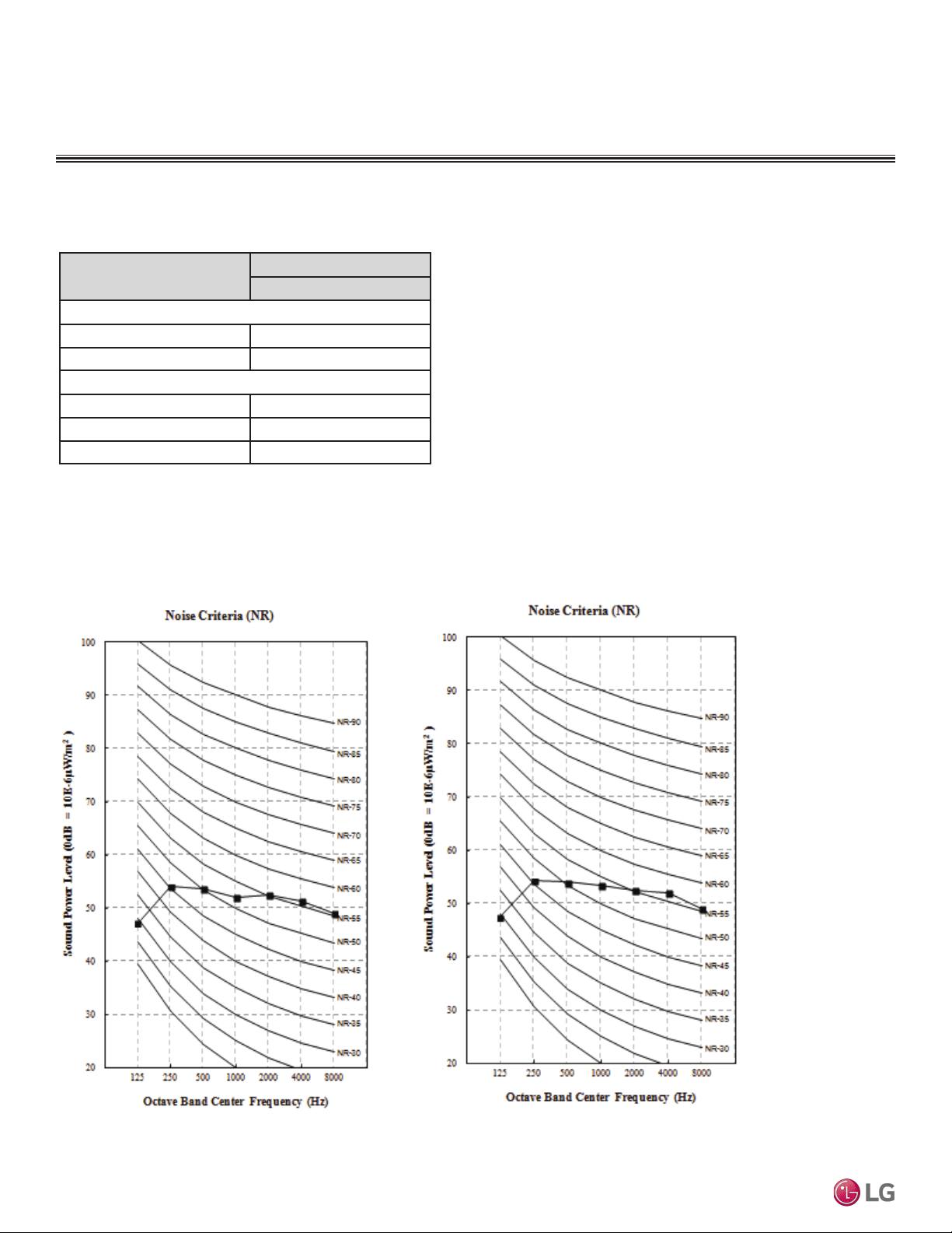
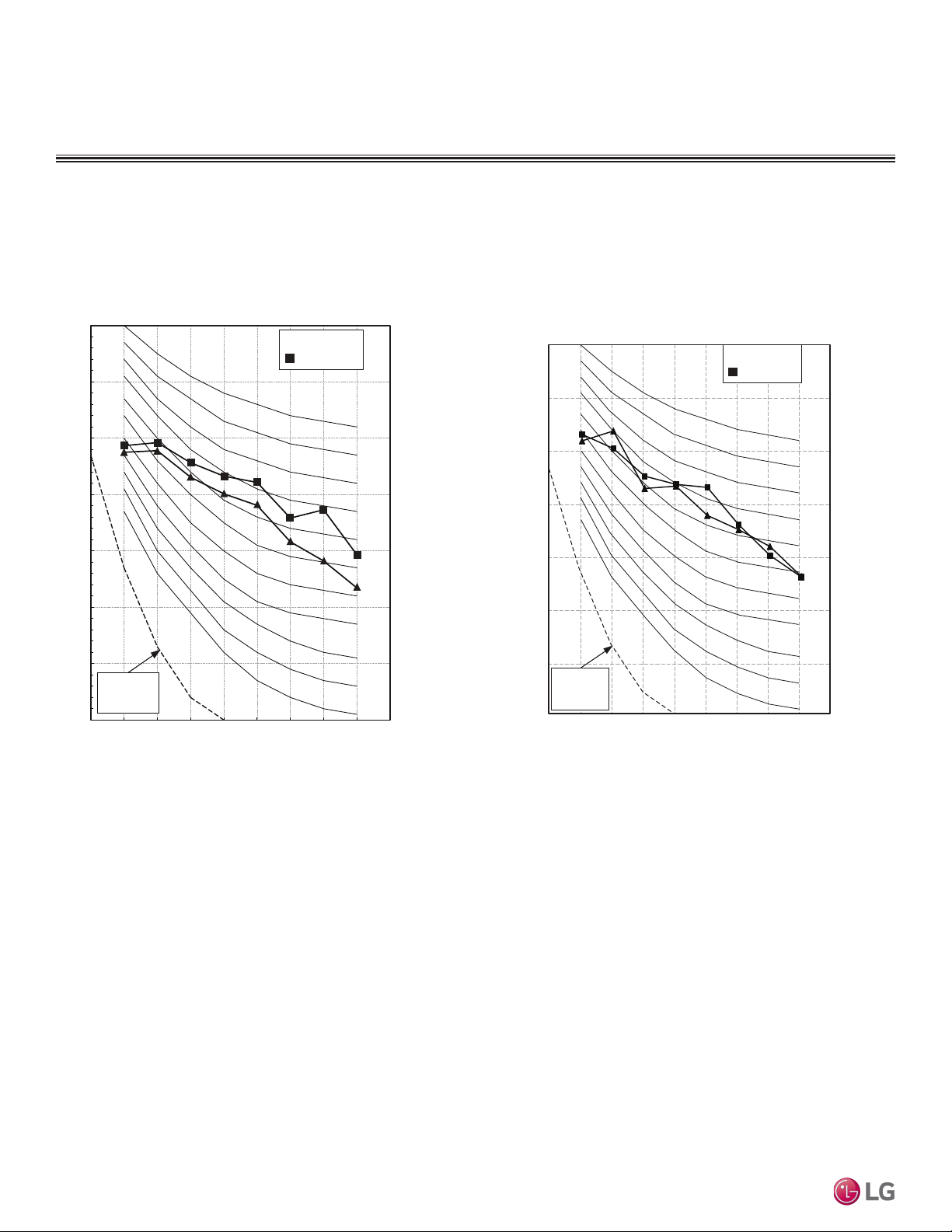
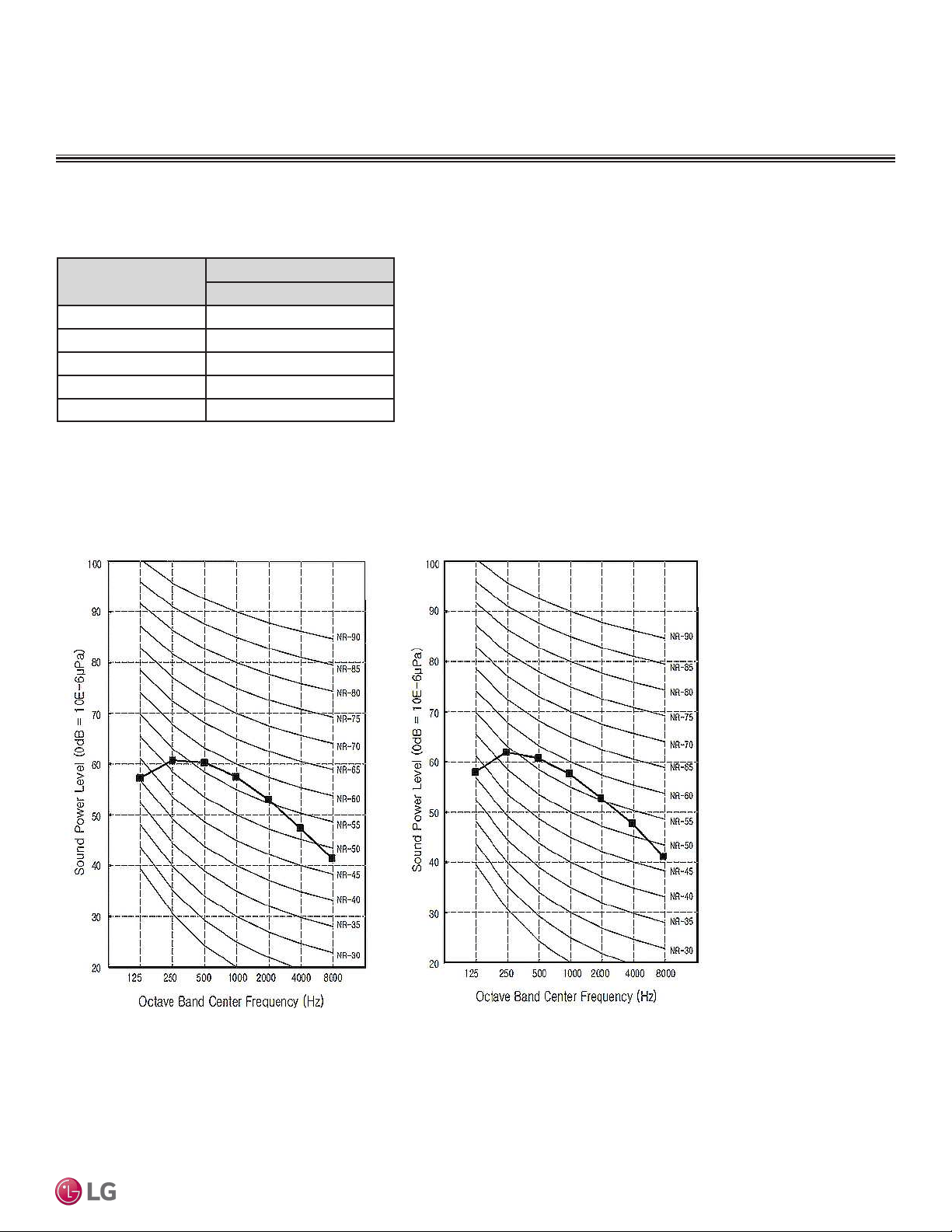
• Data is valid under diffuse field conditions.
• Data is valid under nominal operating conditions.
• Sound power level is measured using rated conditions, and
tested in a reverberation room per ISO 3741 standards.
• Sound level will vary depending on a range of factors such as
construction (acoustic absorption coefficient) of particular area
in which the equipment is installed.
• Reference acoustic intensity: 0dB = 10E-6μW/m
2
Table 8: Vertical Air Handling Unit Sound Power Levels.
Sound Power Levels
ACOUSTIC DATA
Indoor Units
Indoor Unit Model Sound Power Levels dB(A)
High Fan Speed
NJ Frames
LVN180HV4 59
LVN240HV4 60
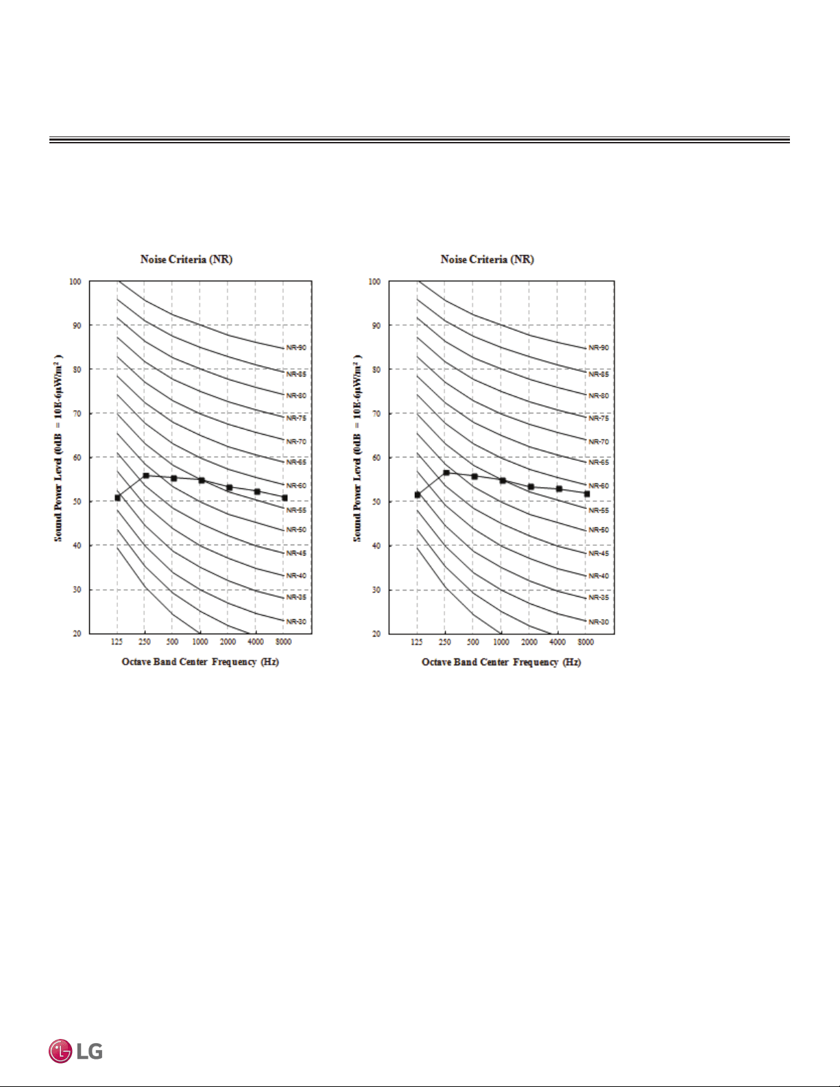
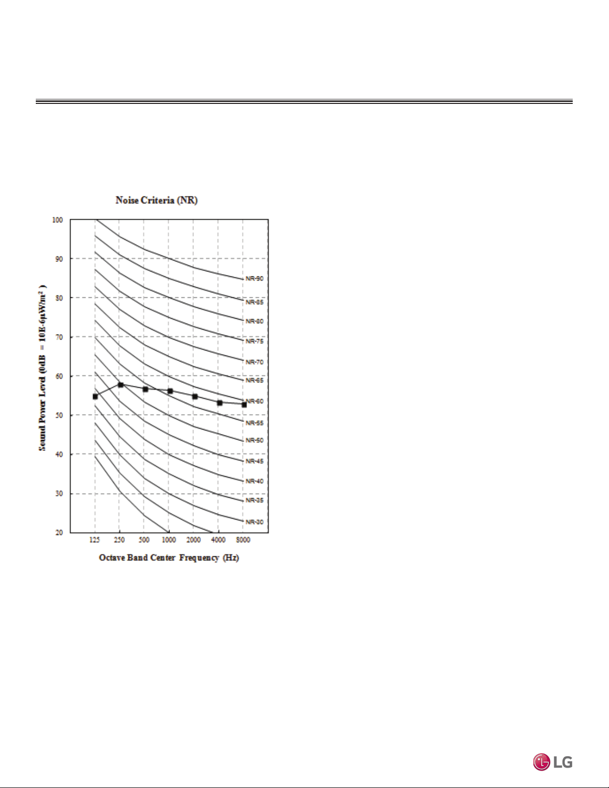
NK Frames
LVN360HV4 61
LVN420HV 61
LVN480HV 62
Figure 12: LVN180HV4 and LVN240HV4 Sound Power Level Diagrams.
Sound Power Level Diagrams for LVN180HV4 and LVN240HV4
LVN180HV4 LVN240HV4
Due to our policy of continuous product innovation, some specications may change without notication.
©LG Electronics U.S.A., Inc., Englewood Cliffs, NJ. All rights reserved. “LG” is a registered trademark of LG Corp.
PRODUCT DATA | 25
Product Data
Sound Power Level Diagrams for LVN360HV4 and LVN420HV
Figure 13: LVN360HV4 and LVN420HV Sound Power Level Diagrams.
LVN360HV4 LVN420HV
ACOUSTIC DATA
Indoor Units
Due to our policy of continuous product innovation, some specications may change without notication.
©LG Electronics U.S.A., Inc., Englewood Cliffs, NJ. All rights reserved. “LG” is a registered trademark of LG Corp.
26 | PRODUCT DATA
Single Zone Vertical Air Handling Unit Engineering Manual
Sound Power Level Diagram for LVN480HV
Figure 14: LVN480HV Sound Power Level Diagram.
LVN480HV
ACOUSTIC DATA
Indoor Units
Due to our policy of continuous product innovation, some specications may change without notication.
©LG Electronics U.S.A., Inc., Englewood Cliffs, NJ. All rights reserved. “LG” is a registered trademark of LG Corp.
PRODUCT DATA | 27
Product Data
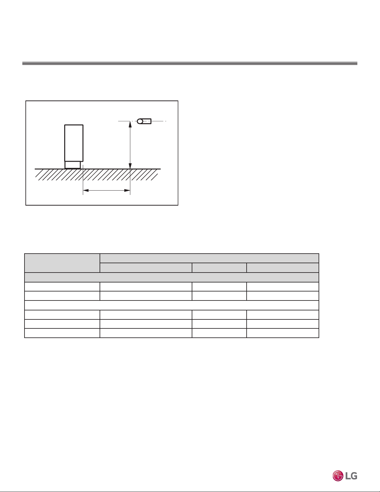
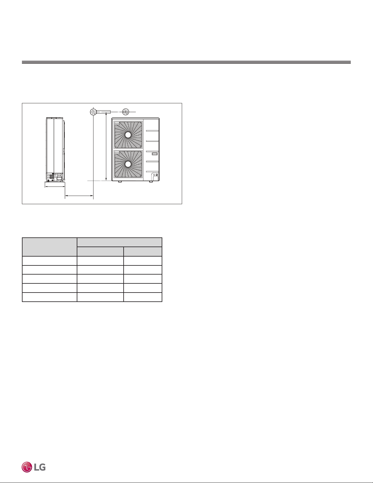
• Measurements taken with no attenuation and units operating at full
load normal operating condition.
• Sound level will vary depending on a range of factors such as con-
struction (acoustic absorption coefficient) of particular area in which
the equipment is installed.
• Sound power levels are measured in dB(A)±3.
• Tested in anechoic chamber per ISO Standard 3745.
Figure 15: Vertical Air Handling Unit Outdoor Unit Sound Pressure Level
Measurement Location.
3.3 ft.
4.9 ft.
D
Table 9: Vertical Air Handling Unit Outdoor Unit Sound Pressure Levels (dB[A]).
Outdoor Unit Model Sound Pressure Level [dB(A)]
Cooling Heating
LUU188HV 48 52
LUU248HV 48 52
LUU368HV 52 54
LUU428HV 52 54
LUU488HV 52 54
ACOUSTIC DATA
Outdoor Unit Sound Pressure Level Measurement
Outdoor Unit Sound Pressure Levels
Outdoor Units
Due to our policy of continuous product innovation, some specications may change without notication.
©LG Electronics U.S.A., Inc., Englewood Cliffs, NJ. All rights reserved. “LG” is a registered trademark of LG Corp.
28 | PRODUCT DATA
Single Zone Vertical Air Handling Unit Engineering Manual
Octave Band Center Frequency (Hz)
Octave Band Sound Pressure Level (0dB = 20μPa)
10
20
30
40
50
60
70
80
63 125 250 500 1000 2000 4000 8000
NC-15
NC-20
NC-25
NC-30
NC-35
NC-40
NC-45
NC-50
NC-55
NC-60
NC-65
Approximate
Hearing
Threshold
▲ Cooling
Heating
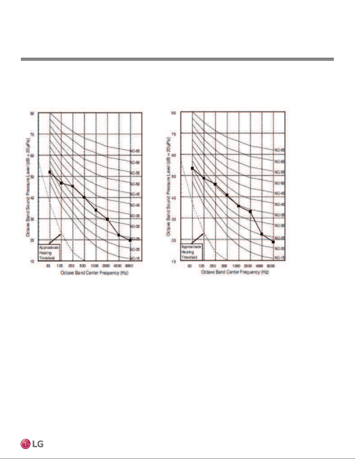
LUU188HV , LUU248HV
Outdoor Unit Sound Pressure Diagrams
Figure 16: LUU188HV , LUU248HV Sound Pressure Level
Diagram.
Octave Band Sound Pressure Level (0dB = 20μPa)
Octave Band Center Frequency (Hz)
10
20
30
40
50
60
70
80
63 125 250 500 1000 2000 4000 8000
NC-15
NC-20
NC-25
NC-30
NC-35
NC-40
NC-45
NC-50
NC-55
NC-60
NC-65
Approximate
Hearing
Threshold
▲ Cooling
Heating
LUU368HV
, LUU428HV
, LUU488HV
Figure 17: LUU368HV, LUU428HV, LUU488HV Sound Pres-
sure Level Diagram.
ACOUSTIC DATA
Outdoor Units
Due to our policy of continuous product innovation, some specications may change without notication.
©LG Electronics U.S.A., Inc., Englewood Cliffs, NJ. All rights reserved. “LG” is a registered trademark of LG Corp.
PRODUCT DATA | 29
Product Data
ACOUSTIC DATA
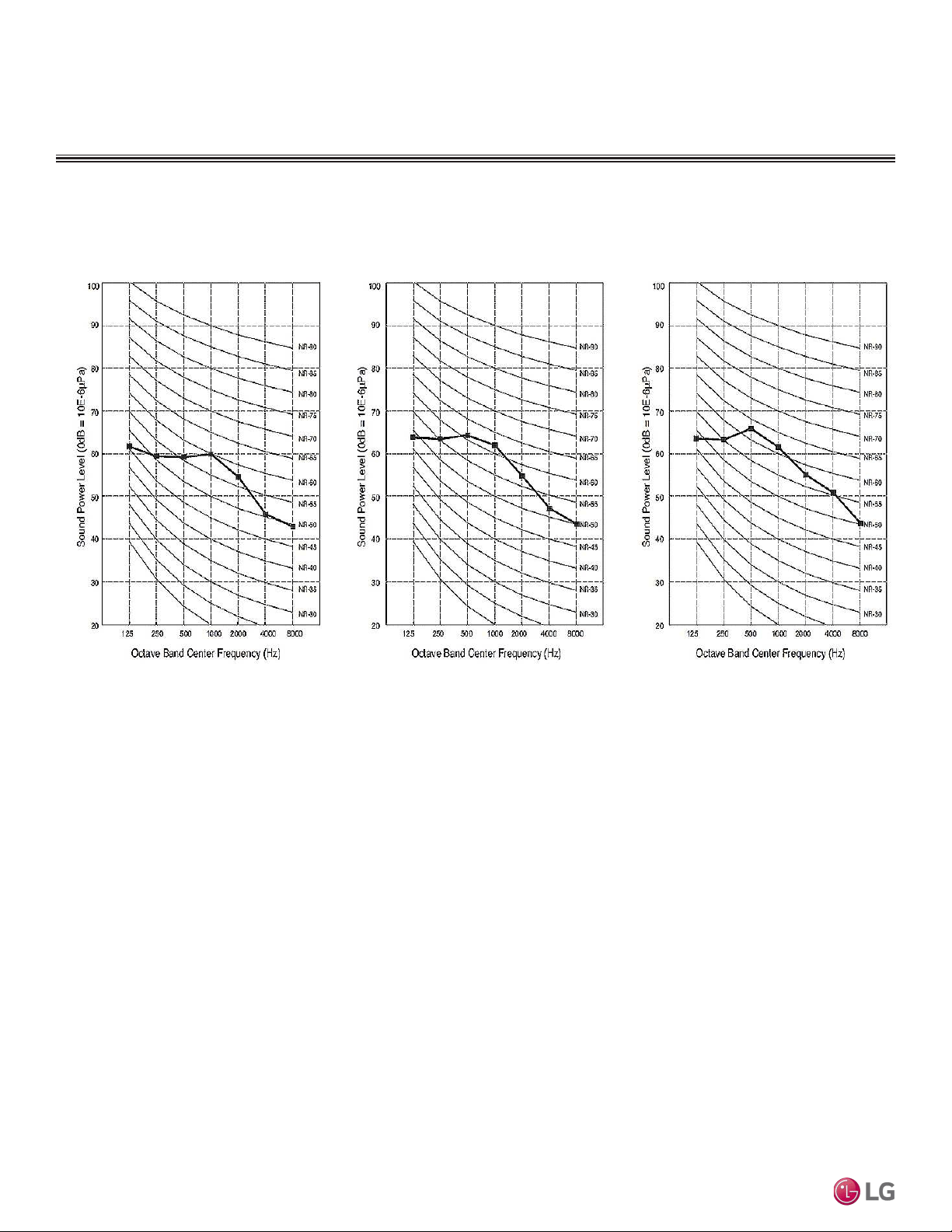
Table 10: Vertical Air Handling Unit ODU Sound Power Levels.
Outdoor Unit Model Sound Power Levels dB(A)
Max
LUU188HV 67
LUU248HV 68
LUU368HV 66
LUU428HV 67
LUU488HV 68
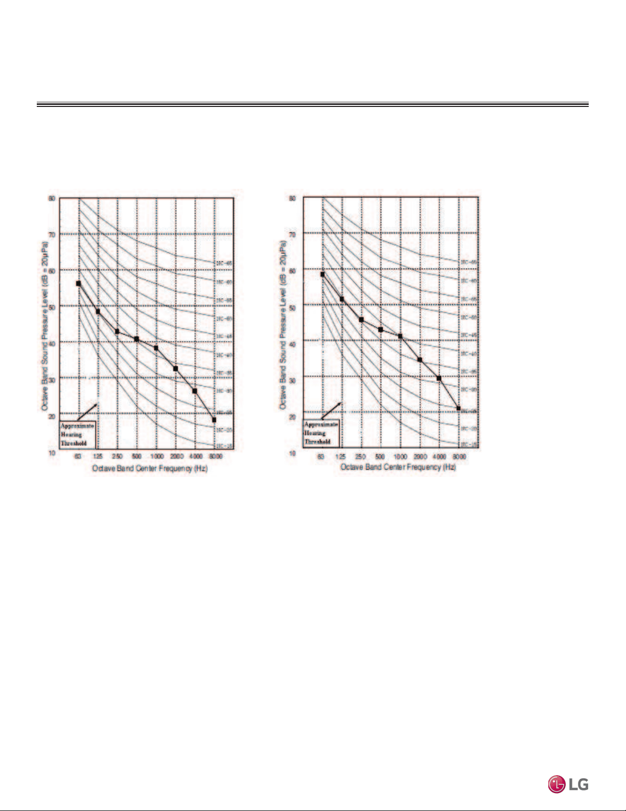
LUU188HV
LUU248HV
Sound Power Level Diagrams for LUU188HV, LUU248HV
Figure 18: LUU188HV , LUU248HV Sound Power Level Diagrams.
Outdoor Unit Sound Power Levels
Outdoor Units
Due to our policy of continuous product innovation, some specications may change without notication.
©LG Electronics U.S.A., Inc., Englewood Cliffs, NJ. All rights reserved. “LG” is a registered trademark of LG Corp.
30 | PRODUCT DATA
Single Zone Vertical Air Handling Unit Engineering Manual
ACOUSTIC DATA
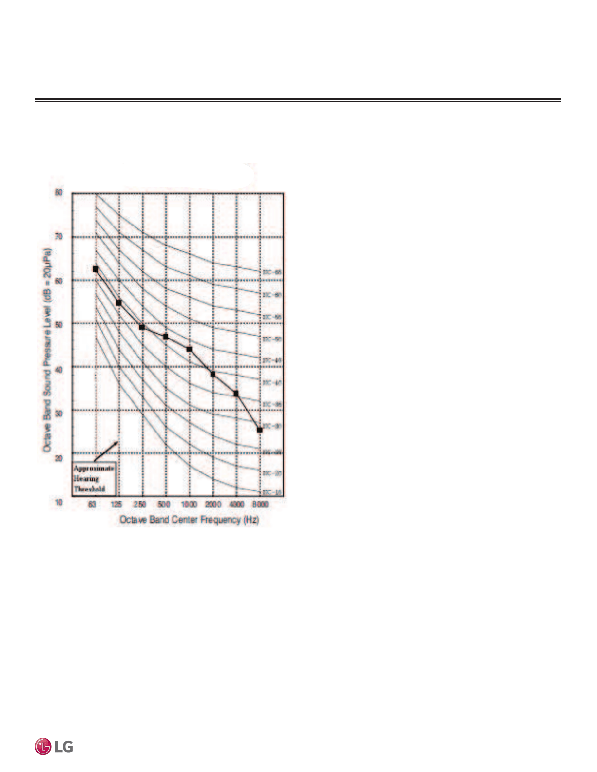
Sound Power Level Diagrams for LUU368HV, LUU428HV, LUU488HV
Figure 19: LUU368HV , LUU428HV, LUU488HV Sound Power Level Diagrams.
LUU368HV LUU428HV
LUU488HV
Outdoor Units
Due to our policy of continuous product innovation, some specications may change without notication.
©LG Electronics U.S.A., Inc., Englewood Cliffs, NJ. All rights reserved. “LG” is a registered trademark of LG Corp.
PRODUCT DATA | 31
Product Data
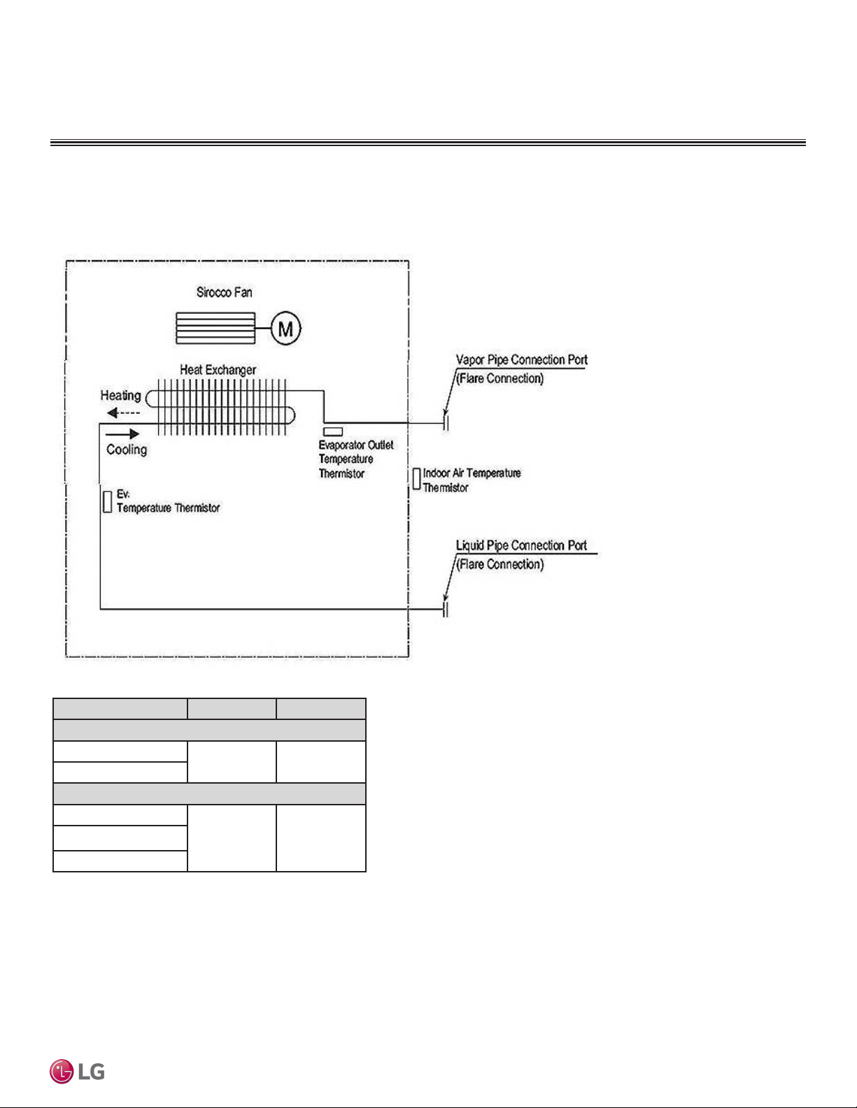
Figure 20: Indoor Unit Refrigerant Flow Diagrams.
Table 11: NJ, NK Frame Refrigerant Pipe Connection Port Diameters.
Indoor Unit Model Liquid (inch) Vapor (inch)
NJ Frames
LVN180HV4
3/8 5/8
LVN240HV4
NK Frames
LVN360HV4
3/8 5/8
LVN420HV
LVN480HV
Refrigerant Flow Diagrams for LVN180HV4, LVN240HV4, LVN360HV4, LVN-
420HV, LVN480HV
REFRIGERANT FLOW DIAGRAM
Indoor Units
Due to our policy of continuous product innovation, some specications may change without notication.
©LG Electronics U.S.A., Inc., Englewood Cliffs, NJ. All rights reserved. “LG” is a registered trademark of LG Corp.
32 | PRODUCT DATA
Single Zone Vertical Air Handling Unit Engineering Manual
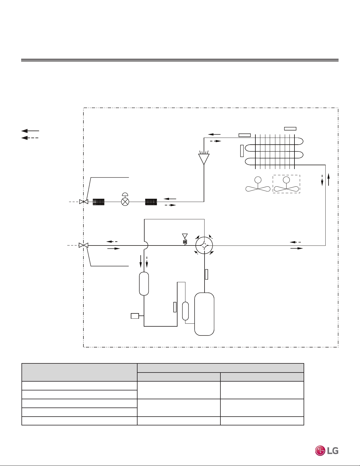
Outdoor Units
REFRIGERANT FLOW DIAGRAM
Description (Based on Cooling Mode)
PCB Connector
Suction Temperature Thermistor
CN-TH3 CN-TH3
Discharge Temperature Thermistor
Condenser Outlet Temperature Thermistor
CN-TH2 CN-TH2
Outdoor Ambient Air Temperature Thermistor
Condenser Inlet Temperature Thermistor CN-TH4 CN-TH4
Table 12: Vertical Air Handling Unit ODU LUU188~488HV Thermistor Details.
Refrigerant Flow
Cooling
Heating
MM
High Pressure
Sensor
4 way
36k/42k model only
Valve
Discharge
Temperature
Thermistor
Suction
Temperature
Fusible
Plug
Thermistor
Accumulator
Inverter
Compressor
Strainer Strainer
Condenser Out
Temperature
Thermistor
Outdoor Ambient Air
Temperature
Thermistor
Ø3/8
Flare Connection
Ø5/8
Flare Connection
Condensing
Temperature
Thermistor
Electronic
Expansion Valve
Liquid Side
Piping
Vapor Side
Piping
SVC
SVC
CN-TH2
CN-TH2
CN-TH3
CN-TH3
Figure 21: LUU188HV, LUU248HV, LUU368HV, LUU428HV, LUU488HV Refrigerant Flow Diagrams.
Refrigerant Flow Diagrams for LUU188HV, LUU248HV, LUU368HV, LUU428HV,
LUU488HV
Due to our policy of continuous product innovation, some specications may change without notication.
©LG Electronics U.S.A., Inc., Englewood Cliffs, NJ. All rights reserved. “LG” is a registered trademark of LG Corp.
PRODUCT DATA | 33
Product Data
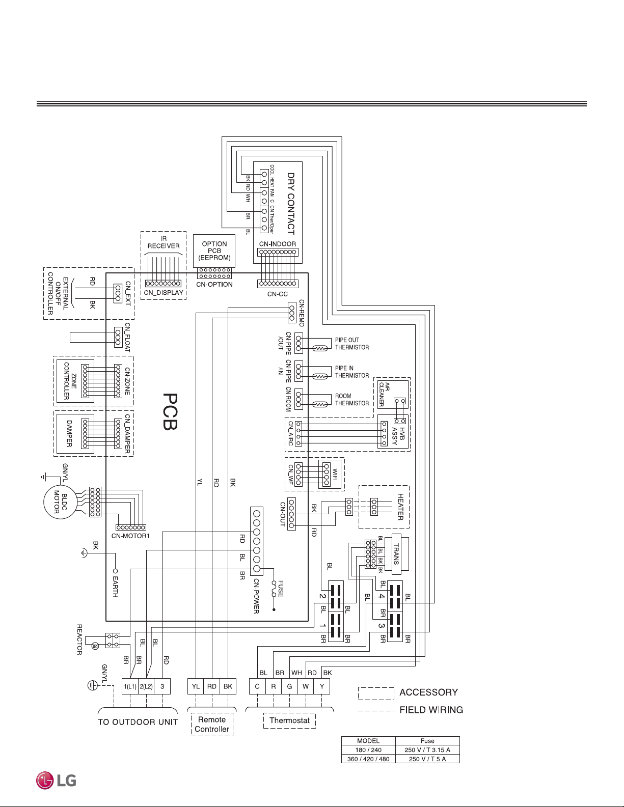
INDOOR UNIT WIRING DIAGRAM
LVN180HV4, LVN240HV4, LVN360HV4, LVN420HV, LVN480HV
Figure 22: Indoor Unit Wiring Diagrams.
Due to our policy of continuous product innovation, some specications may change without notication.
©LG Electronics U.S.A., Inc., Englewood Cliffs, NJ. All rights reserved. “LG” is a registered trademark of LG Corp.
34 | PRODUCT DATA
Single Zone Vertical Air Handling Unit Engineering Manual
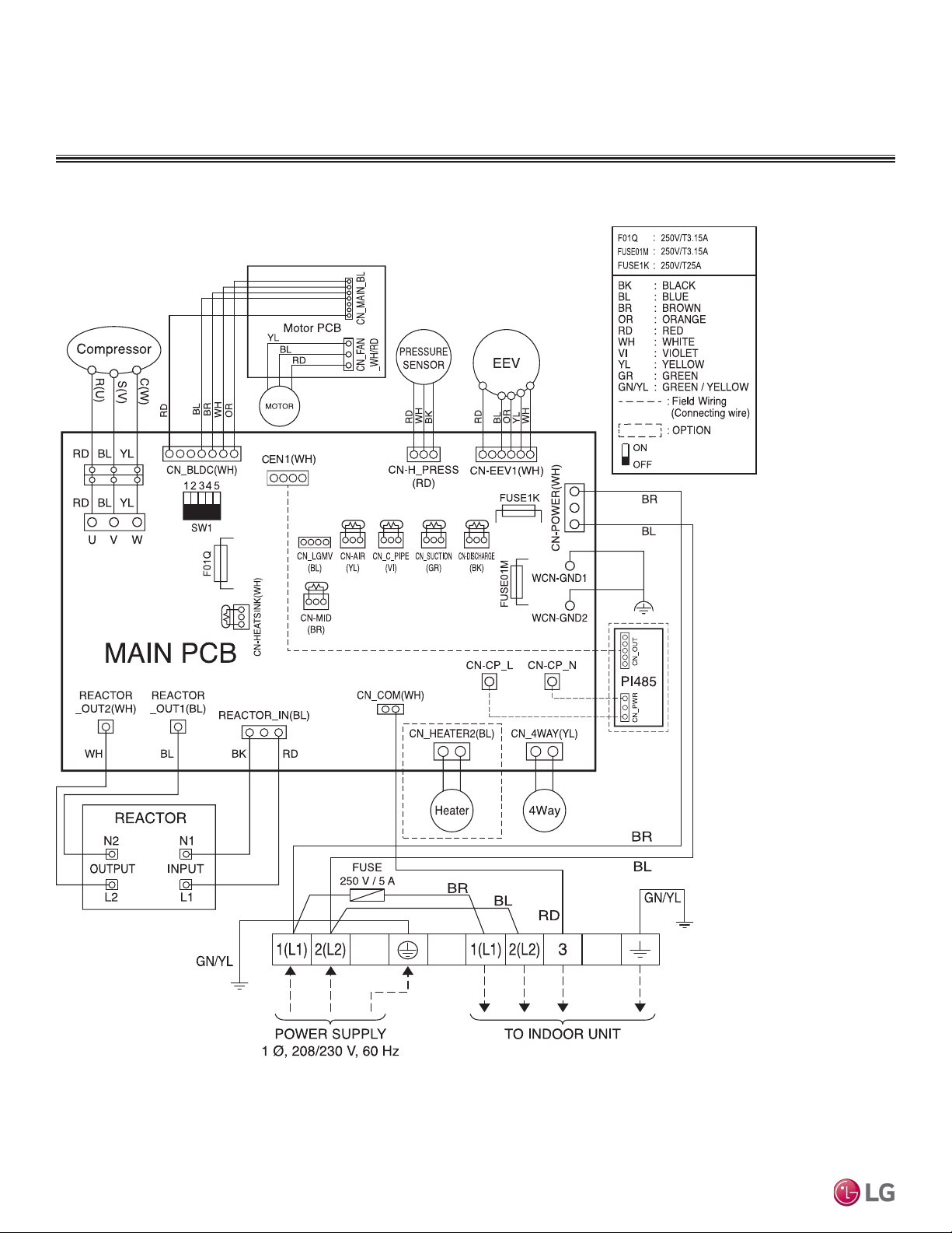
OUTDOOR UNIT WIRING DIAGRAM
LUU188HV, LUU248HV
Figure 23: Outdoor Unit LUU188HV, LUU248HV Wiring Diagrams.
Due to our policy of continuous product innovation, some specications may change without notication.
©LG Electronics U.S.A., Inc., Englewood Cliffs, NJ. All rights reserved. “LG” is a registered trademark of LG Corp.
PRODUCT DATA | 35
Product Data
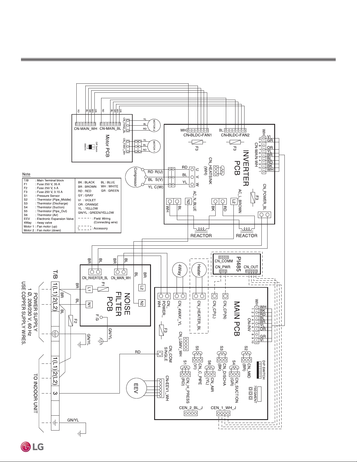
OUTDOOR UNIT WIRING DIAGRAM
LUU368HV, LUU428HV, LUU488HV
Figure 24: Outdoor Unit LUU368HV, LUU428HV, LUU488HV Wiring Diagrams.
Due to our policy of continuous product innovation, some specications may change without notication.
©LG Electronics U.S.A., Inc., Englewood Cliffs, NJ. All rights reserved. “LG” is a registered trademark of LG Corp.
36 | PRODUCT DATA
Single Zone Vertical Air Handling Unit Engineering Manual
Table 13: NJ/NK Frame Wiring Diagram Legend.
ELECTRICAL WIRING
Terminal Purpose Function
CN-POWER
AC Power supply AC Power line
CN-MOTOR1 Fan motor output Motor output of BLDC
CN_OUT Heater Connection for heater
CN-D/PUMP Drain pump output AC output for drain pump
CN-FLOAT Float switch input Float switch sensing
CN-ZONE Zone controller Zone controller connection
CN-OPTION Optional PCB EPROM Option PCB connection
CN-EXT External ON / OFF con-
troller
External ON / OFF controller con-
nection
CN-DISPLAY Display Display of indoor status
CN-CC Dry contact Dry Contact connection
CN-PIPE/OUT (RD) Discharge pipe sensor Pipe out thermistor
CN-LEAK (VI) Refrigerant leak detector Refrigerant leak detector connection
CN-PIPE/IN (WH) Suction pipe sensor Pipe in thermistor
CN-REMO (GN) Wired remote controller Wired remote control connection
CN-ROOM (YL) Room sensor Room air thermistor
CN-DAMPER Damper Controller Damper connection
CN-AIRC Air Cleaner Air Cleaner connection
CN-WF Wifi Wifi Module connection
NJ/NK Frame Wiring Diagram Legend
Due to our policy of continuous product innovation, some specications may change without notication.
©LG Electronics U.S.A., Inc., Englewood Cliffs, NJ. All rights reserved. “LG” is a registered trademark of LG Corp.
PRODUCT DATA | 37
Product Data
Table 14: NJ/NK Frame DIP Switch Settings.
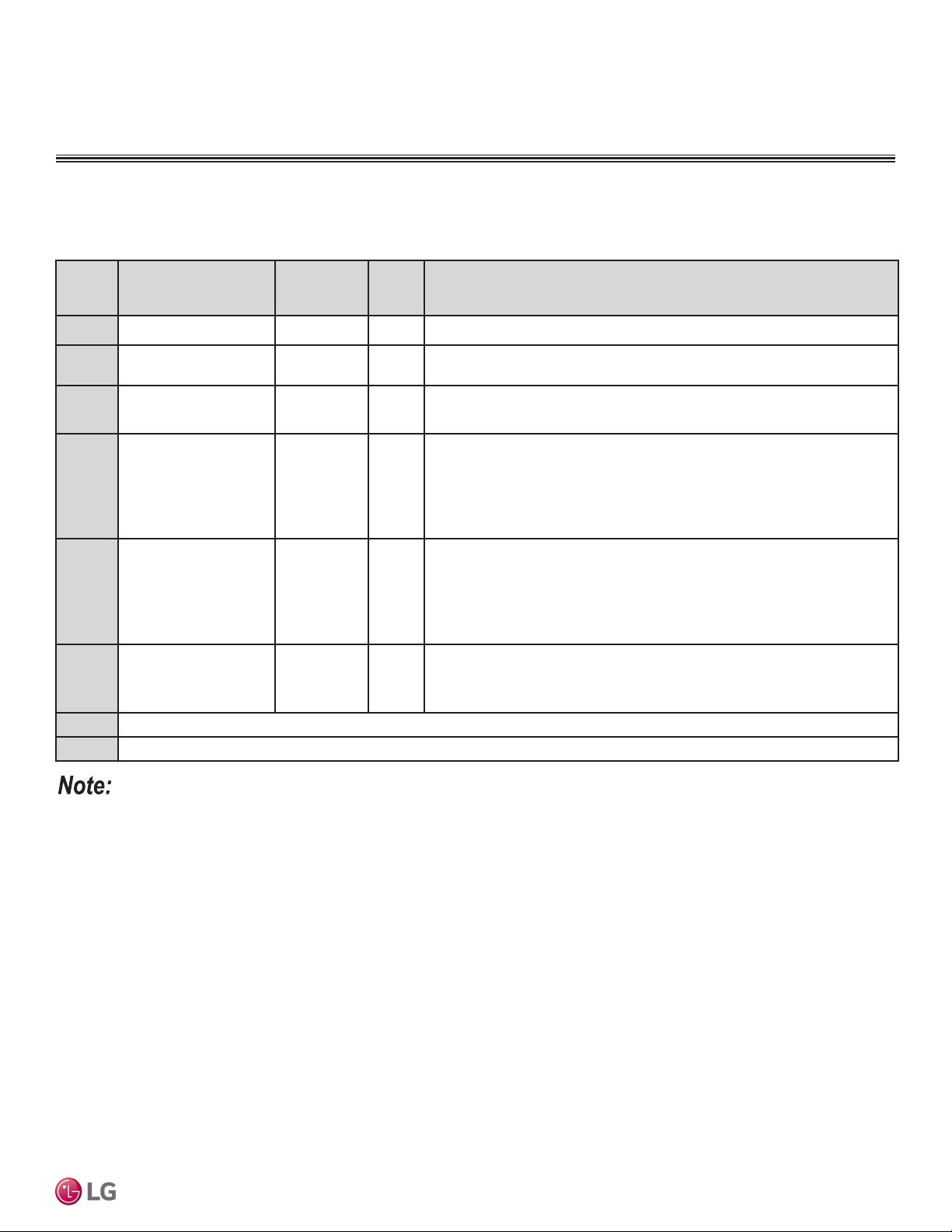
Dip Switch Settings for Indoor Unit PCB
Dip Switch Settings
To operate the indoor unit without Internal Electric Heater, Dip switch 1, 2, 6, 8 must be set OFF.
To operate the indoor unit with Internal Electric heater, Dip switch 6 must be set ON.
• SW6 ON: Automatic Heater operation: Heater operates automatically.
• SW6 OFF: Manual Heater operation: Owner’s involvement is required for on/off operation.
If you operate the indoor unit with Internal Electric heater with Dip switch 5, note the following:
• SW5 ON: Fan operates continuously. During defrosting or oil return operation, uninterrupted heating can be attained, as a result of continu-
ous heater and fan operation.
• SW5 OFF: Fan discontinuous operation. There would be reduction in heating capacity while defrosting or oil return operation.
Dip
Switch
Function Off On Description
SW1 COMMUNICATION
Off (default) _
_
SW2 CYCLE Off (default) _
_
SW3 GROUP CONTROL Master Slave Group control setting using 7-Day Programmable Controller; selects Master/
Slave on each indoor unit.
SW4 DRY CONTACT
MODE
Variable Auto Sets operation mode for optional Dry Contact accessory.
1. Variable: Auto or Manual Mode can be set through 7-Day Programmable
Controller or Wireless Remote Controller (factory default setting is Auto if
there is no setting).
2. Auto: For Dry Contact, it is always Auto mode.
SW5 CONTINUOUS FAN Off On Selects continuous fan for ducted indoor units.
1. On: Indoor unit fan will always operate at a set fan speed, except when the
system is off, or the outdoor unit is in defrost mode (when the outdoor unit is
in defrost mode, the fan will operate at super low fan speed).
2. Off: Indoor unit fan speed can be changed by on / off.
SW6 HEATER INTERLOCK Off On Selects heater interlock function for Vertical Air Handling units.
1. On: Automatic (heater will automatically operate during heating mode).
2. Off: Manual (heater needs to be manually turned on during heating mode).
SW7
Off
SW8
Off
ELECTRICAL WIRING
Due to our policy of continuous product innovation, some specications may change without notication.
©LG Electronics U.S.A., Inc., Englewood Cliffs, NJ. All rights reserved. “LG” is a registered trademark of LG Corp.
38 | PRODUCT DATA
Single Zone Vertical Air Handling Unit Engineering Manual
General Power Wiring / Communications Cable Guidelines
• Follow manufacturer’s circuit diagrams displayed on the inside of the control box cover.
• Have a separate power supply for the indoor units.
• Provide a circuit breaker switch between the power source and the indoor unit.
• Confirm power source specifications.
• Properly ground the outdoor unit and the indoor unit per NEC and local codes.
• Connect the wiring firmly so that the wires cannot be easily pulled out.
• Confirm that the electrical capacity is sufficient.
• Power supply to the outdoor unit must be selected based on NEC and local codes. Maximum allowable voltage fluctuation ±10% or name-
plate rated value.
• It is recommended that a circuit breaker is installed, especially if conditions could become wet or moist.
• Include a disconnect in the power wiring system. Add an air gap contact separation of at least 1/8 inch in each active (phase) conductor.
• Any openings where the field wiring enters the cabinet must be completely sealed.
Do not install power wiring to the outdoor unit and the communication / connection (power) cable to the indoor unit in the same conduit.
Use separate conduits.
Power Wiring / Communications Cable Specifications
• Power wiring to the outdoor unit must be solid or stranded, and must comply with the applicable local and national electric codes.
• Communication cable from the outdoor unit to the indoor unit must be a minimum of 18 AWG, four (4) conductor, shielded or unshielded (if
shielded, must be grounded to chassis at ODU only) and must comply with applicable local and national codes.
• Communication cable from indoor unit to remote controller(s) is to be 22 AWG, 3-conductor, twisted, stranded, unshielded. Wiring must
comply with all applicable local and national codes.
• Terminal screws may become loose during transport. Properly tighten the terminal connections during installation or risk electric shock,
physical injury, or death.
• Loose wiring may cause unit to malfunction, overheat, and catch fire, resulting in severe injury or death.
• Terminal screws may loosen during transport. Properly tighten the terminal connections during installation or risk equipment malfunction or
property damage�
• Loose wiring may cause unit malfunction, the wires to burnout or the terminal to overheat and catch fire. There is a risk of equipment mal-
function or property damage�
A voltage drop may cause the following problems:
• Magnetic switch vibration, fuse breaks, or disturbance to the normal function of an overload protection device.
• Compressor will not receive the proper starting current.
ELECTRICAL CONNECTIONS

Due to our policy of continuous product innovation, some specications may change without notication.
©LG Electronics U.S.A., Inc., Englewood Cliffs, NJ. All rights reserved. “LG” is a registered trademark of LG Corp.
PRODUCT DATA | 39
Product Data
Power Supply
Circuit Breaker
Ground Wiring
Outdoor Unit
Indoor Unit
Figure 25: LV180HV4 and LV240HV4 General Power/Communications System Schematic.
Figure 26: LV360HV4, LV480HV, and LV488HV General Power/Communications System Schematic.
Power Supply
Circuit Breaker
Ground Wiring
Outdoor Unit Indoor Unit
ELECTRICAL CONNECTIONS
• Secure the separate wires in the control box panel using zip ties.
• Secure wiring with accessory clamps so that it does not touch the piping.
• Use a conduit for the communications cable / power wiring from the outdoor unit to the indoor units.
• Make sure the communications cable / power wiring from the outdoor units to the indoor units, and the power wiring to the outdoor unit are
separate, otherwise, the outdoor unit operation may be affected by electrical noise and will malfunction or fail.
Due to our policy of continuous product innovation, some specications may change without notication.
©LG Electronics U.S.A., Inc., Englewood Cliffs, NJ. All rights reserved. “LG” is a registered trademark of LG Corp.
40 | PRODUCT DATA
Single Zone Vertical Air Handling Unit Engineering Manual
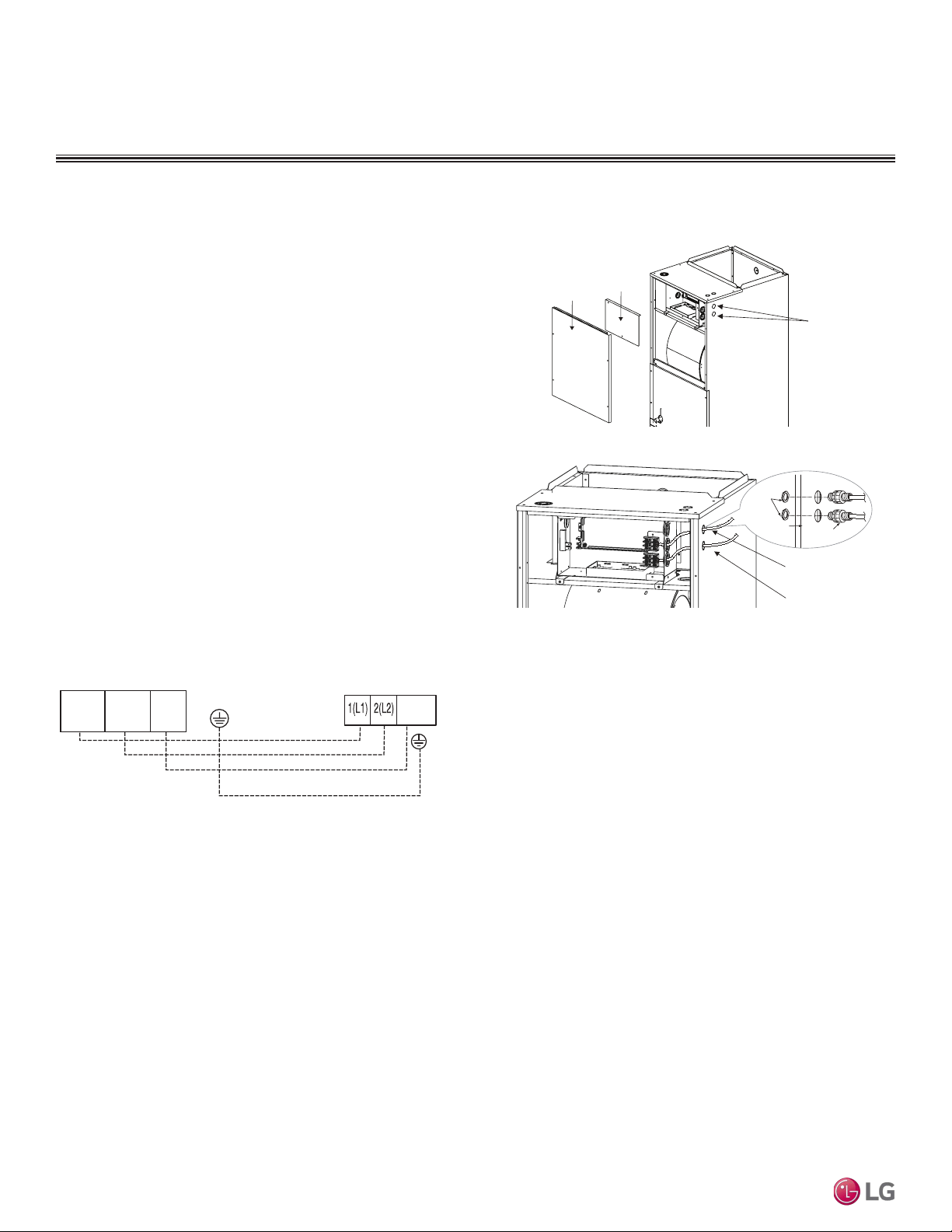
Access Holes
for Wiring
Control
Box Cover
Top Front
Panel
Connection Cable
Communications Cable
Nut
Conduit
Mounting Plate
1/2-inch Conduit
Connecting the Power Wiring and Communications Cable
1. To access the terminal block, first unscrew the top front panel,
and then unscrew the cover from the control box.
2. Knockout the access holes for the wiring. Insert the power wiring/
communications cable from the outdoor unit through the conduits,
pass the conduits through the designated access holes, and
then insert the conduits into the control box. To prevent electro-
magnetic interference and product malfunction, leave a space
between the power wiring and communications cable outside of
the indoor unit.
3. Connect the power wiring and communications cables to the
appropriate terminals on the indoor unit control board. Verify
that the color and terminal numbers from the outdoor unit wiring
match the color and terminal numbers on the indoor unit.
4. Fill in any gaps around the conduit access holes with sealant to
prevent foreign particles from entering the indoor unit.
Figure 27: Connecting the Power Wiring and Communications Cable.
Figure 28: Indoor Unit to Outdoor Unit Power Wiring / Communications Cable
Connections.
ELECTRICAL CONNECTIONS
Indoor Unit Terminal Block
1(L1 )2(L2)
GND
3
Outdoor Unit Terminal Block
GND
GRN /
YLW
BR
BL
RD
3
Due to our policy of continuous product innovation, some specications may change without notication.
©LG Electronics U.S.A., Inc., Englewood Cliffs, NJ. All rights reserved. “LG” is a registered trademark of LG Corp.
PRODUCT DATA | 41
Product Data
Indoor Unit Terminal Block
1(L1 )2(L2)
GND
3
Branch Distribution Unit
GRN /
YLW
BR
BL
RD
CN-REMO
YL
RD BK
Comm.
12V
Power
Ground
Figure 29: PZCWRC1 LG Wired Remote Extension Cable.
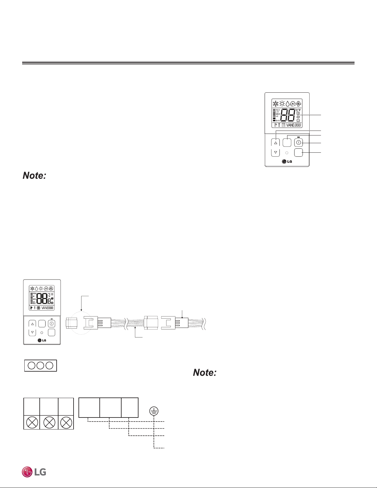
Controller Options
Vertical Air Handling indoor units include LG-supplied wired controller (PQRCVCL0QW), but other
optional LG-supplied wired controllers are available. The wireless handheld controller (Model No.
PQWRHQ0FDB) is also an optional accessory with use of the wired controller.
• Operation Display Panel: Displays operation conditions.
• Temperature Control Button: Sets desired temperature.
• Fan Speed Button: Sets desired fan speed.
• On / Off Button: Turns system operation on and off.
• Mode Selection Check Button: Selects the operation mode: Cooling, Heating, Auto, Dry
(Dehumidification), or Fan.
Figure 30: PQRCVCL0QW Wired
Controller.
TEMP
FA N
SPEED
OPER
MODE
Operation Display
Panel
Temperature Control
Button
Fan Speed Button
On/Off Button
Mode Selection
Check Button
Each function will display on the LED for about three (3) seconds when the power is rst cycled on.
Verify the connectors are properly inserted.
C/BOX Cable (Plug type)
Extension cable
To Indoor Unit
CN-REMO
Terminal
TEMP
FAN
SPEED
OPER
MODE
Figure 31: Wired Controller Connection on the Indoor Unit Terminal Block.
When using eld-supplied controller cable, make sure to connect the
yellow to yellow (communications wire), red to red (12V power wire), and
black to black (ground wire) terminals from the remote controller to the
indoor unit terminal blocks.
Wired Controller Connections
Controllers can connect to the indoor unit in one of two different ways.
1. LG Wired Remote Extension Cable with Molex plug (PZCWRC1; sold separately) that connects to the CN-REMO terminal on the indoor
unit PCB.
2. Field-supplied controller cable that connects to the indoor unit terminal block (must be at least UL2547 or UL1007, and at least FT-6 rated
if local electric and building codes require plenum cable usage). Communication cable from indoor unit to remote controller(s) is to be 22
AWG, 3-conductor, twisted, stranded, unshielded. Wiring must comply with all applicable local and national codes.
ELECTRICAL CONNECTIONS
Due to our policy of continuous product innovation, some specications may change without notication.
©LG Electronics U.S.A., Inc., Englewood Cliffs, NJ. All rights reserved. “LG” is a registered trademark of LG Corp.
42 | PRODUCT DATA
Single Zone Vertical Air Handling Unit Engineering Manual
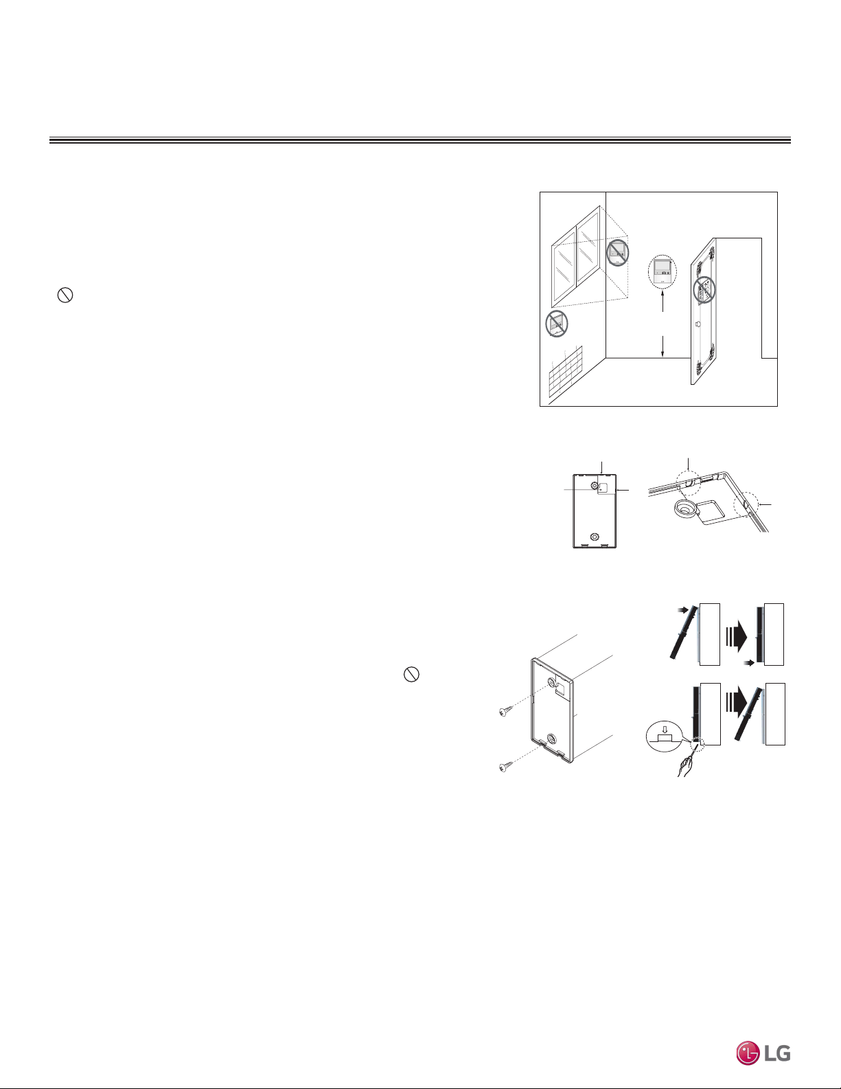
Figure 32: Proper Location for the Wired Controller.
4 to 5 feet
above the floor
NO
NO
NO
YES
Remote Controlle r
TEMP
Remote Controller
TEMP
Re
m
o
t
e Co
nt
r
oller
TEMP
Wired controllers include a sensor to detect room temperature. To maintain
comfort levels in the conditioned space, the wired controller must be installed in
a location away from direct sunlight, high humidity, and where it could be directly
exposed to cold air. Controller must be installed four (4) to five (5) feet above the
floor where its LED display can be read easily, in an area with good air circula-
tion, and where it can detect an average room temperature.
Do not install the wired controller near or in:
• Drafts or dead spots behind doors and in corners
• Hot or cold air from ducts
• Radiant heat from the sun or appliances
• Concealed pipes and chimneys
• An area where temperatures are uncontrolled, such as an outside wall
Wired Controller Placement
Assigning the Thermistor for Temperature Detection
Each indoor unit includes a return air thermistor assigned to sense the temperature. If a wired controller is installed, there is a choice of
sensing temperature with either the indoor unit return air thermistor or the thermistor in the wired controller. It is also an option to set both
thermistors to sense temperature so that indoor unit bases its operation on the first thermistor to reach the designated temperature differen-
tial. For applicable indoor units, an optional Remote Temperature Sensor can be used in lieu of the return air thermistor—either alone or in
conjunction with a wired controller thermistor as previously described.
Hanging the Wired Controller
1. The controller wiring / cable can be installed in one of three directions: top,
back, or on the right side. If top or right side installation is desired, remove
cable guide grooves on the controller, and then position wiring / cable on
applicable side.
2. Choose and mark the area of installation, and then screw the wall plate into
place (using the provided parts). Install the controller wall plate to fit the elec-
trical box if one is present. Ensure that no gaps exist between the wall plate
and the wall itself.
3. Arrange wiring / cables so as not to interfere with the controller circuitry.
Position the wired controller on the wall plate. Snap into place by pressing the
bottom part of the wired controller onto the wall plate. Make sure that no gaps
exist between the wired controller and the wall plate on all sides.
4. To remove wired controller from the wall plate, insert a screwdriver into the
two holes at the bottom. Twist screwdriver to release controller. Do not
damage the controller components when removing.
Back
To p
To p
Right
Side
Right
Side
Wall Wall
Wall Wall
Installing the Controller
Removing the Controller
Figure 33: Removing the Cable Guide Grooves.
Figure 34: Attaching the
Wall Plate.
Figure 35: Installing /
Removing the Controller.
ELECTRICAL CONNECTIONS
Due to our policy of continuous product innovation, some specications may change without notication.
©LG Electronics U.S.A., Inc., Englewood Cliffs, NJ. All rights reserved. “LG” is a registered trademark of LG Corp.
PRODUCT DATA | 43
Product Data
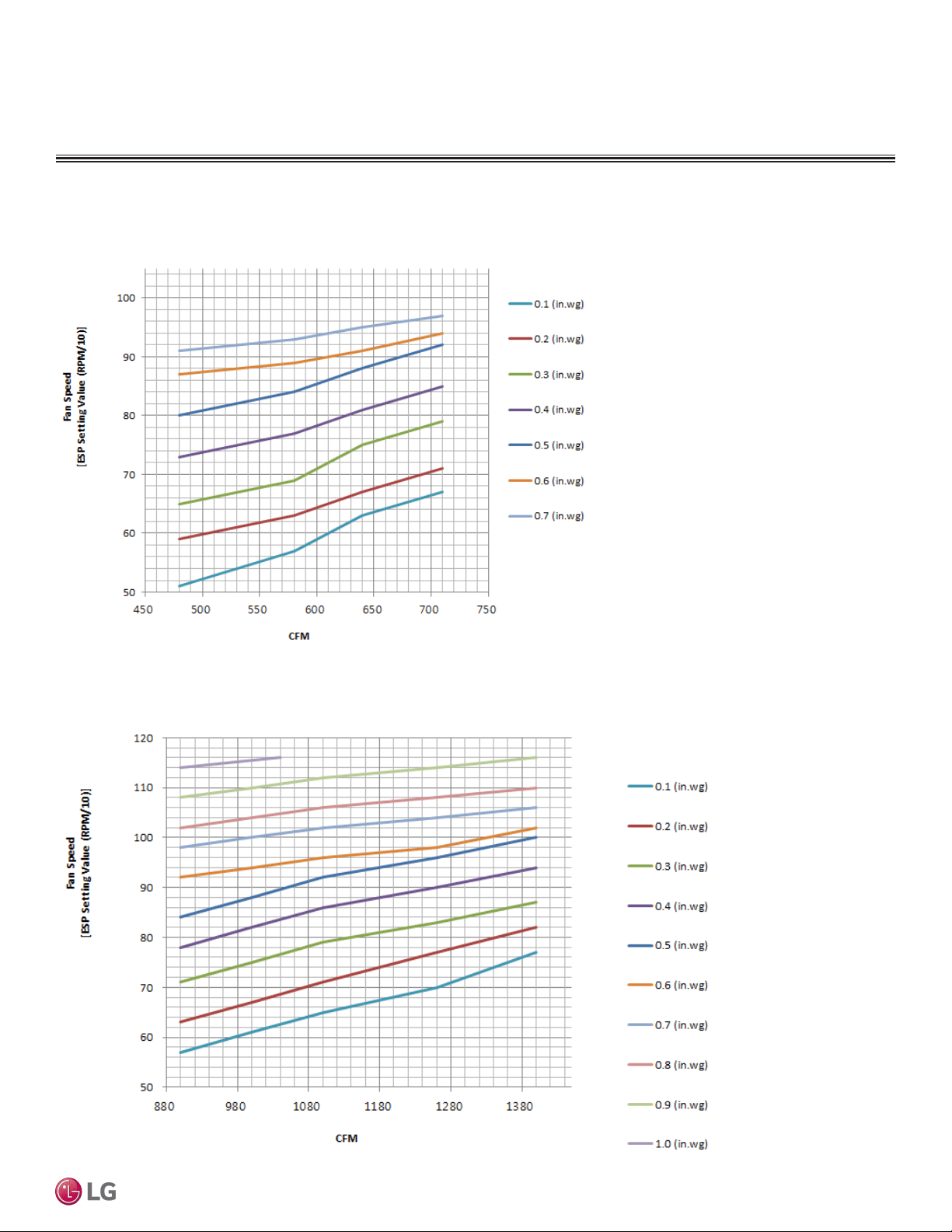
Figure 36: ESP Setting Values (NJ frame).
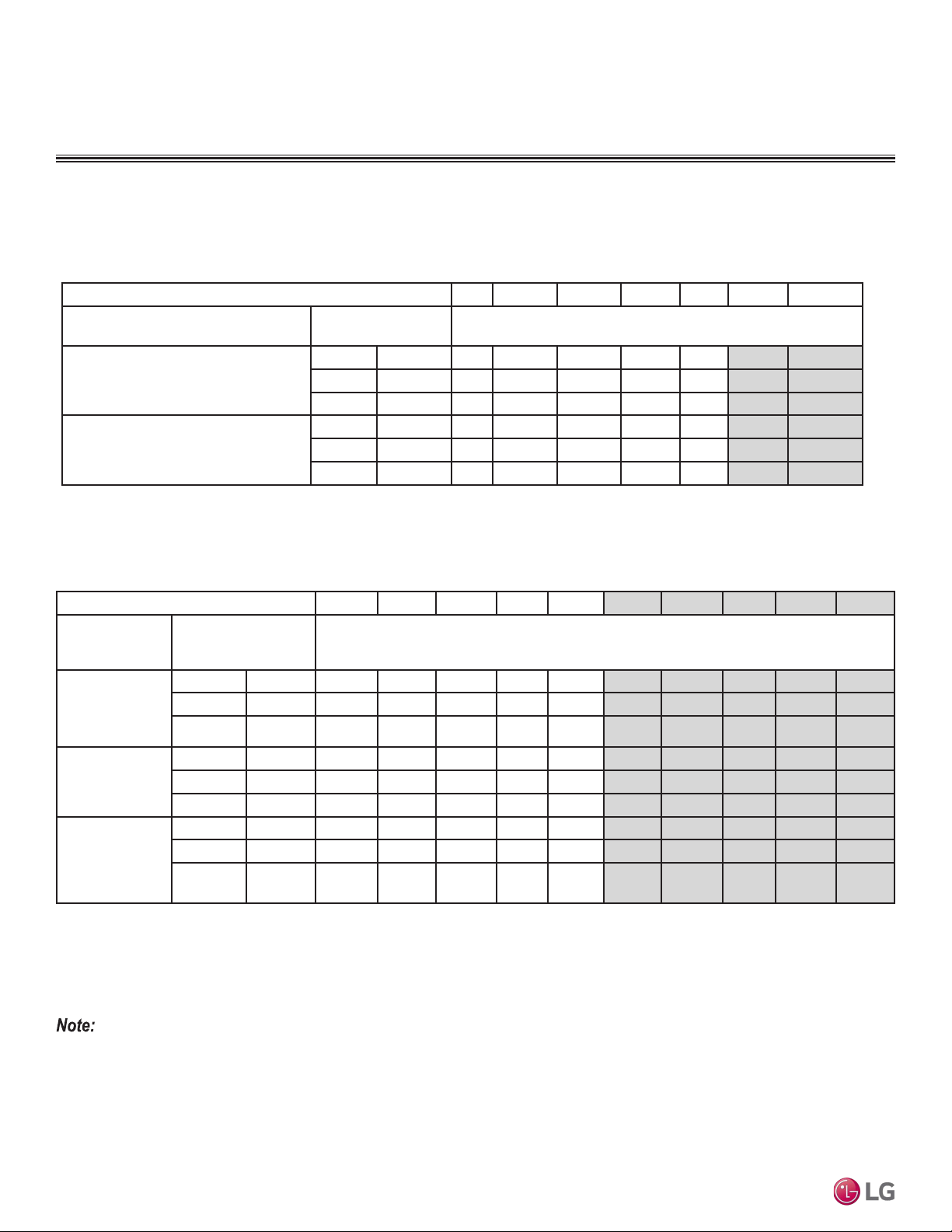
Figure 37: ESP Setting Values (NK frame).
EXTERNAL STATIC PRESSURE AND AIRFLOW RANGES
External Static Pressure Setting Values (NK frame)
External Static Pressure (ESP) Setting Values (NJ frame)
Due to our policy of continuous product innovation, some specications may change without notication.
©LG Electronics U.S.A., Inc., Englewood Cliffs, NJ. All rights reserved. “LG” is a registered trademark of LG Corp.
44 | PRODUCT DATA
Single Zone Vertical Air Handling Unit Engineering Manual
EXTERNAL STATIC PRESSURE AND AIRFLOW RANGES
NJ, NK Frames
Table 15: Vertical Air Handling Unit NJ Frame Indoor Unit External Static Pressure and Air Flow Tables.
Static Pressure (in. wg) 0.1 0.2 0.3 0.4 0.5 0.6 0.7
Model No. / Nominal Capacity
of System (Btu/h)
Airow Rate / CFM Setting Value (in. WG)
1
LVN180HV4/
18,000
High 640 63 67 75 81 88 91 95
Mid 580 57 63 69 77 84 89 93
Low 480 51 59 65 73 80 87 91
LVN240HV4/
24,000
High 710 67 71 79 85 92 94 97
Mid 640 63 67 75 81 88 91 95
Low 480 51 59 65 73 80 87 91
IDU External Static Pressure Setting Values
LVN180HV4 and LVN240HV4 (NJ Frame)
Table 16: Vertical Air Handling Unit NK Frame Indoor Unit External Static Pressure and Air Flow Tables.
IDU External Static Pressure Setting Values
LVN360HV4, LVN420HV, LVN480HV (NK Frame)
Static Pressure (in. wg) 0.1 0.2 0.3 0.4 0.5 0.6 0.7 0.8 0.9 1
Model No. / Nomi-
nal Capacity
of System (Btu/h)
Airow Rate / CFM Setting Value (in. WG)
1
LVN360HV4/
36,000
High 1,100 65 71 79 86 92 96 102 106 112 _
Mid 1,000 61 67 75 82 88 94 100 104 110 116*
Low 900 57 63 71 78 84 92 98 102 108 114
LVN420HV/
42,000
High 1,260 70 77 83 90 96 98 104 108 116* _
Mid 1,100 65 71 79 86 92 96 102 106 114 _
Low 1,000 61 67 75 82 88 94 100 104 112 116*
LVN480HV/
48,000
High 1,400 77 82 87 94 100 102 106 110 116* _
Mid 1,260 70 77 83 90 96 98 104 108 114 116*
Low 1,000 61 67 75 82 88 94 100 104 112 116*
• If the ESP is set incorrectly, the air conditioning may malfunction.
• To get the desired air ow and external static pressure combination, use the setting value from the table. Using a setting value other than the values
listed in the table will not provide the desired combination.
1 Unless otherwise noted, vertical air handling units are UL listed up to 0.5 in. wg total
static pressure, including coil, case, duct work pressure drop, air filter, and largest kW size
heater. Internal static pressure includes coil and case only.
* Airflow rate (CFM) decreases by 3% per 0.1 in. wg.
Factory default status is 0.3 in wg.
Factory default is high static pressure.
Due to our policy of continuous product innovation, some specications may change without notication.
©LG Electronics U.S.A., Inc., Englewood Cliffs, NJ. All rights reserved. “LG” is a registered trademark of LG Corp.
PRODUCT DATA | 45
Product Data
Table 17: Air Filter Static Pressure Drop Factors.
If the air filter has been installed, the ESP value has to be set.
For every increase in static pressure by 0.01 in. wg, the ESP value must be increased
by 1.
Air Filter Static Pressure Drop Factors
Capacity (kBtu/h [tons]) Flow Rate (CFM) Static Pressure Drop (in wg)
18 (1.5) High (640) -0.04
Middle(580) -0.04
Low (480) -0.04
24 (2.0) High (710) -0.04
Middle(640) -0.04
Low (480) -0.04
36 (3.0) High (1100) -0.08
Middle(1000) -0.08
Low (900) -0.08
42 (3.5) High (1260) -0.09
Middle(1100) -0.08
Low (1000) -0.08
48 (4.0) High (1400) -0.09
Middle(1260) -0.09
Low (1000) -0.08
Do not operate with less than the minimum airow. If an airow is used
below the minimum, there is a risk of damage to the product.
Airflow rates in the table above are listed in CFM.
Do not operate with less than the minimum airow. If an air-
ow is used below the minimum, there is a risk of re, which may
lead to physical injury or death.
Table 18: Minimum Airow by Heater Capacity.
Capacity (kBtu/h [tons]) Heater Capacity (kW)
3, 5 8, 10 15 20
18 (1.5) 480 480 Not available Not available
24 (2.0) 480 480 Not available Not available
36 (3.0) 900 900 900 900
42 (3.5) 1000 1000 1000 1000
48 (4.0) 1000 1000 1000 1000
Minimum Airflow by Heater Capacity
EXTERNAL STATIC PRESSURE AND AIRFLOW RANGES
Due to our policy of continuous product innovation, some specications may change without notication.
©LG Electronics U.S.A., Inc., Englewood Cliffs, NJ. All rights reserved. “LG” is a registered trademark of LG Corp.
46 | PRODUCT DATA
Single Zone Vertical Air Handling Unit Engineering Manual
Electric Heater Static Pressure Drop Factors
Table 19: Electric Heater Static Pressure Drop Factors.
Heater Capacity (kW) Static Pressure Drop (in. wg)
0 0
3, 5 -0.01
8, 10 -0.02
15 -0.03
20 -0.04
in wg = inch water gauge
If the electric heater has been installed, then the ESP value has to be set.
For every increase in static pressure by 0.01 in wg, the ESP value must be increased by 1.
If the ESP setting value is inappropriate, the provided safety device will turn the heater off
according to the airflow.
Table 20: Down Flow Static Pressure Drop Factors.
If the air filter has been installed, the ESP value has to be set.
For every increase in static pressure by 0.01 in. wc, the ESP value must be increased by
1.
Capacity (kBtu/h [tons]) Flow Rate (CFM) Static Pressure Drop (in wg)
18 (1.5) High (640) -0.04
Middle(580) -0.04
Low (480) -0.04
24 (2.0) High (710) -0.04
Middle(640) -0.04
Low (480) -0.04
36 (3.0) High (1100) -0.09
Middle(1000) -0.09
Low (900) -0.09
42 (3.5) High (1260) -0.09
Middle(1100) -0.09
Low (1000) -0.09
48 (4.0) High (1400) -0.09
Middle(1260) -0.09
Low (1000) -0.09
Down Flow (optional) Static Pressure Drop Factors
EXTERNAL STATIC PRESSURE AND AIRFLOW RANGES
Due to our policy of continuous product innovation, some specications may change without notication.
©LG Electronics U.S.A., Inc., Englewood Cliffs, NJ. All rights reserved. “LG” is a registered trademark of LG Corp.
PRODUCT DATA | 47
Product Data
Table 21: Down Flow - Air Filter Static Pressure Drop Factors.
If the air filter has been installed, the ESP value has to be set.
For every increase in static pressure by 0.01 in. wc, the ESP value must be increased by
1.
Capacity (kBtu/h [tons]) Flow Rate (CFM) Static Pressure Drop (in wg)
18 (1.5) High (640) -0.04
Middle(580) -0.04
Low (480) -0.04
24 (2.0) High (710) -0.04
Middle(640) -0.04
Low (480) -0.04
36 (3.0) High (1100) -0.06
Middle(1000) -0.06
Low (900) -0.06
42 (3.5) High (1260) -0.07
Middle(1100) -0.06
Low (1000) -0.06
48 (4.0) High (1400) -0.07
Middle(1260) -0.07
Low (1000) -0.06
Down Flow - Air Filter (optional) Static Pressure Drop Factors
Down Flow - Internal Electric Heater Static Pressure Drop Factors
Table 22: Internal Electric Heater Static Pressure Drop Factors.
Heater Capacity (kW) Static Pressure Drop (in. wg)
0 0
3, 5 -0.01
8, 10 -0.01
15 -0.01
20 -0.01
in. wc = inch water column, inAq
If the internal electric heater has been installed, then the ESP value has to be set.
For every increase in static pressure by 0.01 in WC, the ESP value must be increased by
1.
If the ESP setting value is inappropriate, the provided safety device will turn the heater off
according to the airflow.
EXTERNAL STATIC PRESSURE AND AIRFLOW RANGES
Due to our policy of continuous product innovation, some specications may change without notication.
©LG Electronics U.S.A., Inc., Englewood Cliffs, NJ. All rights reserved. “LG” is a registered trademark of LG Corp.
48 | PRODUCT DATA
Single Zone Vertical Air Handling Unit Engineering Manual
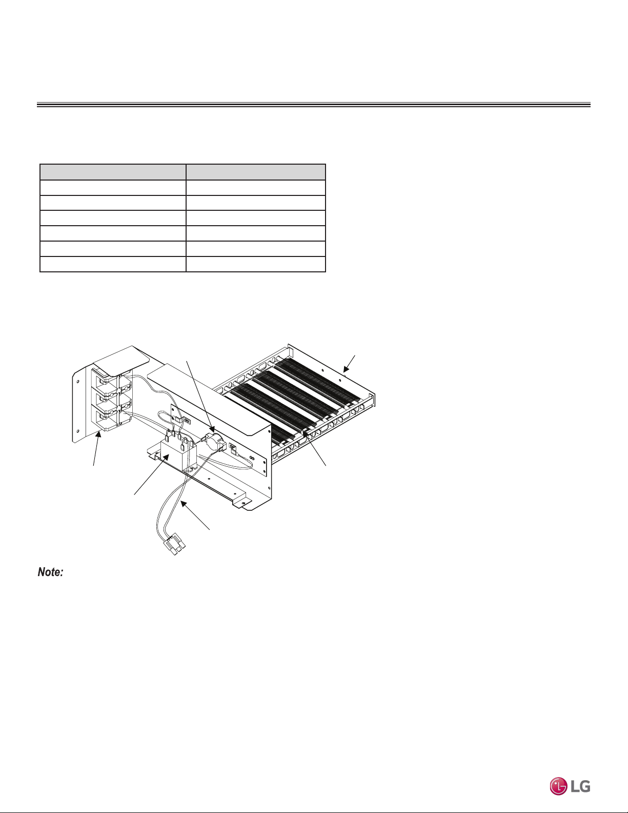
Example: 5kW Capacity Heater
Terminal Block
Relay
Heater Cable
Bi metal
Heater Coil
Bracket
Image shown above may vary depending on model capacity.
Figure 38: Electric Heater.
ACCESSORIES
Accessory Model Number
3kW Electric Heater ANEH033B1
5kW Electric Heater ANEH053B1
8kW Electric Heater ANEH083B2
10kW Electric Heater ANEH103B2
15kW Electric Heater ANEH153B2
20kW Electric Heater ANEH203B2
Table 23: Electric Heater Capacities for Vertical Air Handling Units.
Electric Heater
Due to our policy of continuous product innovation, some specications may change without notication.
©LG Electronics U.S.A., Inc., Englewood Cliffs, NJ. All rights reserved. “LG” is a registered trademark of LG Corp.
PRODUCT DATA | 49
Product Data
Table 24: Electric Heater Capacities.
Indoor Unit Model No. / Capacity (MBh) Model Number / Heater Capacity
ANEH033B1
(3kW)
ANEH053B1
(5kW)
ANEH083B2
(8kW)
ANEH103B2
(10kW)
ANEH153B2
(15kW)
ANEH203B2
(20kW)
LVN180HV4 (18)
√ √ √ √
X X
LVN240HV4 (24)
√ √ √ √
X X
LVN360HV4 (36)
√ √ √ √ √ √
LVN420HV (42)
√ √ √ √ √ √
LVN480HV (48)
√ √ √ √ √ √
ACCESSORIES
IDU ODU Heater kW Accessory Model Note
LVN180HV4 LUU188HV 120 W PQSH1200 Optional
LVN240HV4 LUU248HV 120 W PQSH1200 Optional
LVN360HV4 LUU368HV 120 W PQSH1200 Optional
LVN420HV LUU428HV 120 W PQSH1200 Optional
LVN480HV LUU488HV 120 W PQSH1200 Optional
Drain Pan Heater
Table 25: Drain Pan Heater Capacities.
Electric Heater, continued
√ = Standard feature
X = Not Available
Figure 39: Drain Pan Heater.
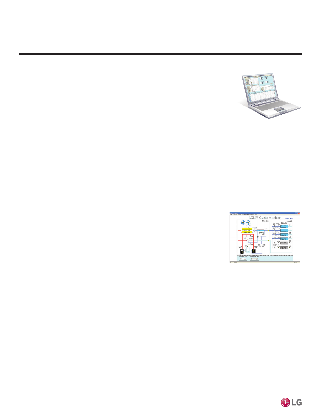
Due to our policy of continuous product innovation, some specications may change without notication.
©LG Electronics U.S.A., Inc., Englewood Cliffs, NJ. All rights reserved. “LG” is a registered trademark of LG Corp.
50 | PRODUCT DATA
Single Zone Vertical Air Handling Unit Engineering Manual
ACCESSORIES
• Actual inverter compressor speed
• Target inverter compressor speed
• Actual outdoor fan speed
• Target outdoor unit fan speed
• Actual superheat
• Target superheat
• Actual subcooler circuit superheat
• Target subcooler circuit superheat
• Main EEV position
• Subcooling EEV position
• Inverter compressor current transducer
value
• Outdoor air temperature
• Actual high pressure/saturation temperature
• Actual low pressure/saturation temperature
• Suction temperature
• Inverter compressor discharge temperature
• Constant speed compressor discharge
temperature
• Front outdoor coil pipe temperature
• Back outdoor coil pipe temperature
• Liquid line pipe temperature
• Subcooler inlet temperature
• Subcooler outlet temperature
• Average indoor unit (IDU) pipe temperature
• Inverter compressor operation indicator
light
• Four-way reversing valve operation
indicator light
• Pressure graph showing actual low pres-
sure and actual high pressure levels
• Error code display
• Operating mode indicator
• Target high pressure
• Target low pressure
• PCB (printed circuit board) version
• Software
version
• Installer
name
• Model no.
of outdoor units
• Site name
• Total number of connected indoor units
• Communication indicator lights
• Indoor unit capacity
• Indoor unit operating mode
• Indoor unit fan speed
• Indoor unit EEV position
• Indoor unit room temperature
• Indoor unit inlet pipe temperature
• Indoor unit outlet pipe temperature
• Indoor unit error code
LG Monitoring View (LGMV) Diagnostic Software and Cable
LGMV software allows the service technician or commissioning agent to connect a computer USB port
to the outdoor unit main printed circuit board (PCB) using an accessory cable without the need for a
separate interface device. The main screen for LGMV allows user to view the following real time data on
one screen:
Additional screens can be accessed by tabs on the main screen:
1. Cycleview: Graphic of internal components including:
2. Graph: Full screen graph of actual high and low pressures and high and low pressure limits. A
sliding bar enables user to go back in time and view data.
3. Control IDU: Enables user to turn on all IDU’s default setpoints of 86°F in heat mode or 64°F in
cool mode.
4. Setting: Converts metric values to imperial values.
5. Making Data: Recording of real time data to a separate file created to be stored on the user’s computer.
6. Loading Data: Recorded data from a saved “.CSV” file can be loaded to create an LGMV session.
7. Electrical Data: The lower half of main screen is changed to show the following:
Figure 40: Sample Cycleview.
• Compressors showing actual speeds
• EEVs
• Indoor Units
• Liquid injection valves
• Temperature and pressure sensors
• Four-way reversing valve
• Outdoor fans showing status and speeds
• Inverter compressor
- Amps
- Volts
- Power Hz
- Inverter control board fan Hz
• Constant compressor
- Current transducer value
- Phase
• CPU: Pentium
®
IV 1.6 GHz
• Operating System: Windows
®
NT/2000/XP/Vista
• Main Memory: 256 MB
• Hard Disk: 600 MB when operating
• Web Browser: Internet Explorer
®
5.0
LGMV is available in different formats, including Mobile LGMV, which is a app for use on wireless devices. Contact your LG
Sales Representative for more information.
In lieu of connecting to the outdoor unit, user has the option to connect to the indoor unit with the use of a USB to RS-485 connector kit.
When connected through the indoor unit, user will not be able to record data.
This software can be used to both commission new systems and troubleshoot existing systems. LGMV data can be recorded to a “.CSV” file
and emailed to an LG representative to assist with diagnostic evaluations.
Recommended Minimum PC Configuration:

“Cooling Capacity Data” on page 52
“Heating Capacity Data” on page 57
“Maximum Heating Capacity Data” on page 62
“Equipment Selection Procedure” on page 67
VERTICAL AIR HANDLING
UNIT PERFORMANCE
DATA
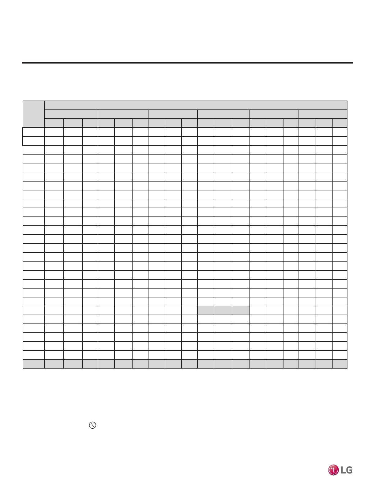
Due to our policy of continuous product innovation, some specications may change without notication.
©LG Electronics U.S.A., Inc., Englewood Cliffs, NJ. All rights reserved. “LG” is a registered trademark of LG Corp.
52 | PRODUCT DATA
Single Zone Vertical Air Handling Unit Engineering Manual
Table 26: Cooling Capacity Table for LUU188HV + LVN180HV4.
Cooling Capacity Table for LV180HV4 (LUU188HV + LVN180HV4)
PERFORMANCE DATA
Cooling Capacity Tables
Outdoor
Air
Temp.
(°F DB)
Indoor Air Temp. °F DB / °F WB
68 / 57 72 / 61 77 / 64 80 / 67 86 / 72 90 / 75
TC SHC PI TC SHC PI TC SHC PI TC SHC PI TC SHC PI TC SHC PI
-4 17.70 12.85 0.80 18.80 13.58 0.83 19.89 13.14 0.86 20.69 13.42 0.87 22.09 13.53 0.88 23.19 13.79 0.90
0 17.69 12.93 0.81 18.79 13.66 0.84 19.88 13.22 0.87 20.68 13.50 0.88 22.08 13.61 0.89 23.18 13.87 0.91
5 17.67 13.04 0.82 18.77 13.77 0.85 19.87 13.34 0.88 20.66 13.62 0.89 22.06 13.73 0.91 23.16 13.99 0.93
10 17.66 13.14 0.83 18.76 13.88 0.86 19.85 13.44 0.89 20.64 13.73 0.90 22.05 13.84 0.92 23.14 14.10 0.94
15 17.65 13.25 0.84 18.74 13.99 0.88 19.84 13.55 0.91 20.63 13.83 0.92 22.03 13.95 0.94 23.12 14.22 0.95
20 17.63 13.35 0.86 18.73 14.10 0.89 19.82 13.65 0.92 20.61 13.94 0.93 22.01 14.06 0.95 23.11 14.33 0.97
25 17.62 13.45 0.87 18.71 14.21 0.90 19.81 13.76 0.93 20.60 14.05 0.94 22.00 14.17 0.96 23.09 14.44 0.98
30 17.60 13.56 0.88 18.70 14.32 0.91 19.79 13.87 0.95 20.58 14.16 0.96 21.98 14.28 0.98 23.07 14.55 1.00
35 17.59 13.66 0.89 18.68 14.43 0.93 19.78 13.97 0.96 20.57 14.27 0.97 21.96 14.39 0.99 23.05 14.66 1.01
40 17.58 13.76 0.91 18.67 14.54 0.94 19.76 14.08 0.97 20.55 14.37 0.98 21.94 14.49 1.00 23.04 14.77 1.02
45 17.56 13.87 0.92 18.66 14.65 0.95 19.75 14.18 0.99 20.53 14.48 1.00 21.93 14.60 1.02 23.02 14.88 1.04
50 17.55 13.97 0.93 18.64 14.75 0.96 19.73 14.29 1.00 20.52 14.59 1.01 21.91 14.71 1.03 23.00 14.99 1.05
55 17.54 14.07 0.94 18.63 14.86 0.98 19.72 14.39 1.01 20.50 14.69 1.02 21.89 14.82 1.04 22.98 15.10 1.06
60 17.52 14.17 0.95 18.61 14.97 0.99 19.70 14.50 1.03 20.49 14.80 1.04 21.88 14.93 1.06 22.97 15.21 1.08
65 17.51 14.27 0.97 18.60 15.08 1.00 19.69 14.60 1.04 20.47 14.91 1.05 21.86 15.03 1.07 22.95 15.32 1.09
70 17.50 14.38 0.98 18.58 15.19 1.01 19.67 14.70 1.05 20.46 15.01 1.06 21.84 15.14 1.08 22.93 15.43 1.10
75 17.08 14.14 1.03 18.16 14.96 1.07 19.24 14.50 1.11 20.03 14.81 1.12 21.41 14.96 1.14 22.50 15.25 1.16
80 16.66 13.90 1.08 17.74 14.72 1.12 18.82 14.29 1.16 19.60 14.61 1.18 20.98 14.77 1.20 22.06 15.07 1.22
85 16.24 13.64 1.14 17.32 14.47 1.18 18.40 14.06 1.22 19.17 14.39 1.24 20.55 14.57 1.26 21.63 14.88 1.28
90 15.82 13.39 1.19 16.90 14.22 1.23 17.97 13.84 1.28 18.75 14.17 1.29 20.12 14.36 1.32 21.20 14.69 1.34
95 15.37 13.25 1.24 16.44 14.09 1.29 17.51 13.73 1.33 18.00 13.86 1.35 19.65 14.29 1.38 20.72 14.62 1.40
100 14.99 12.89 1.30 16.06 13.74 1.34 17.13 13.40 1.39 17.77 13.65 1.41 19.28 13.98 1.43 20.35 14.32 1.46
105 14.62 12.54 1.35 15.69 13.38 1.40 16.76 13.08 1.45 17.53 13.43 1.46 18.90 13.67 1.49 19.97 14.02 1.52
110 14.24 12.11 1.40 15.32 12.95 1.45 16.39 12.67 1.50 17.16 13.03 1.52 18.53 13.29 1.55 19.60 13.64 1.58
115 13.87 11.75 1.45 14.94 12.58 1.51 16.01 12.34 1.56 16.79 12.70 1.58 18.15 12.97 1.61 19.22 13.33 1.64
118 13.65 11.66 1.49 14.72 12.51 1.54 15.79 12.27 1.60 16.56 12.64 1.61 17.93 12.92 1.64 19.00 13.29 1.68
122 13.57 11.63 1.53 14.64 12.48 1.58 15.71 12.25 1.64 16.49 12.62 1.66 17.85 12.91 1.69 18.92 13.28 1.72
DB: Dry Bulb Temperature (°F) WB: Wet Bulb Temperature (°F) TC: Total Capacity
(kBtu/h)
SHC: Sensible Capacity (kBtu/h) PI: Power Input (kW) (includes compressor, indoor fan
motor and outdoor fan motor)
1. All capacities are net, evaporator fan motor heat is deducted.
2. Cooling operating range with the Low Ambient Baffle Kit (sold separately) is -4°F to
+122°F.
3. Grey shading indicates reference data. When operating the unit at this temperature,
these values can be different by discontinuous operation.
4. Direct interpolation is permissible.
Do not extrapolate.
Nominal capacity as rated: 0 ft. above sea level with 25 ft. of refrigerant piping.
0 ft. level difference between outdoor and indoor units.
Nominal cooling capacity rating obtained with air entering the indoor unit at 80ºF dry bulb
(DB) and 67ºF wet bulb (WB), and outdoor ambient conditions of 95ºF dry bulb (DB) and
75ºF wet bulb (WB).
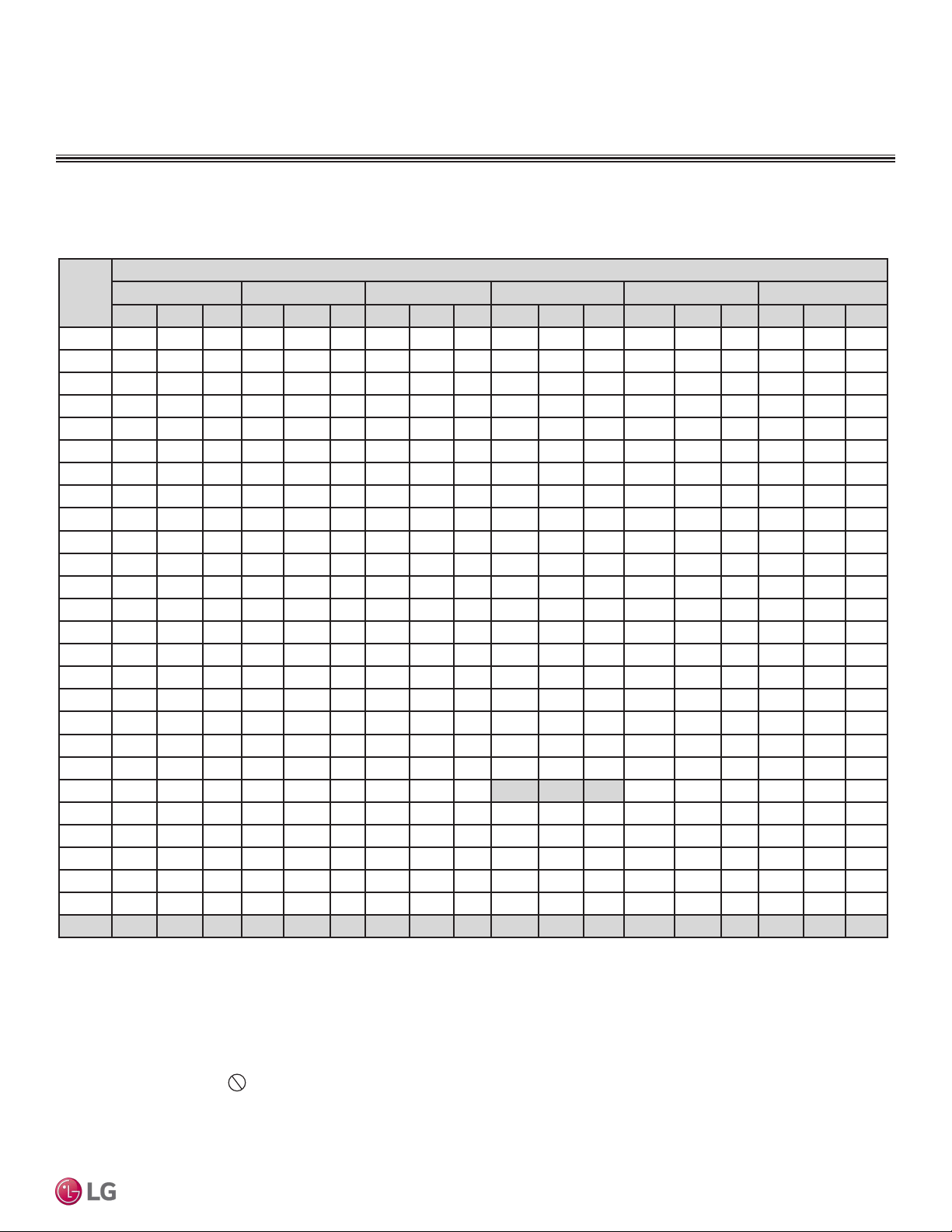
Due to our policy of continuous product innovation, some specications may change without notication.
©LG Electronics U.S.A., Inc., Englewood Cliffs, NJ. All rights reserved. “LG” is a registered trademark of LG Corp.
PRODUCT DATA | 53
Product Data
Table 27: Cooling Capacity Table for LUU248HV + LVN240HV4.
Cooling Capacity Table for LV240HV4 (LUU248HV + LVN240HV4)
Out-
door Air
Temp.
(°F DB)
Indoor Air Temp. °F DB / °F WB
68 / 57 72 / 61 77 / 64 80 / 67 86 / 72 90 / 75
TC SHC PI TC SHC PI TC SHC PI TC SHC PI TC SHC PI TC SHC PI
-4 23.60 17.36 1.14 25.06 18.34 1.18 26.53 17.75 1.22 27.58 18.13 1.23 29.46 18.28 1.26 30.92 18.63 1.28
0 23.58 17.46 1.15 25.05 18.44 1.19 26.51 17.86 1.23 27.57 18.23 1.25 29.44 18.39 1.27 30.91 18.74 1.30
5 23.56 17.61 1.17 25.03 18.60 1.21 26.49 18.01 1.25 27.55 18.39 1.27 29.42 18.55 1.29 30.88 18.90 1.32
10 23.55 17.75 1.18 25.01 18.75 1.23 26.47 18.16 1.27 27.53 18.54 1.29 29.39 18.70 1.31 30.86 19.05 1.34
15 23.53 17.89 1.20 24.99 18.90 1.25 26.45 18.30 1.29 27.50 18.69 1.31 29.37 18.84 1.33 30.83 19.20 1.36
20 23.51 18.03 1.22 24.97 19.05 1.26 26.43 18.44 1.31 27.48 18.83 1.32 29.35 18.99 1.35 30.81 19.35 1.38
25 23.49 18.17 1.24 24.95 19.20 1.28 26.41 18.59 1.33 27.46 18.98 1.34 29.33 19.14 1.37 30.79 19.50 1.40
30 23.47 18.31 1.25 24.93 19.34 1.30 26.39 18.73 1.35 27.44 19.12 1.36 29.30 19.28 1.39 30.76 19.65 1.42
35 23.46 18.45 1.27 24.91 19.49 1.32 26.37 18.87 1.37 27.42 19.27 1.38 29.28 19.43 1.41 30.74 19.80 1.43
40 23.44 18.59 1.29 24.89 19.64 1.33 26.35 19.01 1.38 27.40 19.41 1.40 29.26 19.58 1.43 30.72 19.95 1.45
45 23.42 18.73 1.31 24.87 19.78 1.35 26.33 19.15 1.40 27.38 19.56 1.42 29.24 19.72 1.44 30.69 20.10 1.47
50 23.40 18.87 1.32 24.85 19.93 1.37 26.31 19.30 1.42 27.36 19.70 1.44 29.21 19.87 1.46 30.67 20.24 1.49
55 23.38 19.00 1.34 24.84 20.07 1.39 26.29 19.44 1.44 27.34 19.85 1.46 29.19 20.01 1.48 30.64 20.39 1.51
60 23.37 19.14 1.36 24.82 20.22 1.41 26.27 19.58 1.46 27.32 19.99 1.47 29.17 20.16 1.50 30.62 20.54 1.53
65 23.35 19.28 1.37 24.80 20.37 1.42 26.25 19.72 1.48 27.29 20.13 1.49 29.15 20.30 1.52 30.60 20.69 1.55
70 23.33 19.42 1.39 24.78 20.51 1.44 26.23 19.86 1.49 27.27 20.28 1.51 29.13 20.45 1.54 30.57 20.84 1.57
75 22.77 19.10 1.47 24.21 20.20 1.52 25.66 19.58 1.58 26.70 20.01 1.59 28.55 20.20 1.62 29.99 20.60 1.66
80 22.21 18.77 1.54 23.65 19.88 1.60 25.09 19.30 1.66 26.13 19.73 1.68 27.97 19.95 1.71 29.42 20.36 1.74
85 21.65 18.43 1.62 23.09 19.55 1.68 24.53 18.99 1.74 25.57 19.44 1.76 27.40 19.68 1.79 28.84 20.10 1.83
90 21.09 18.08 1.69 22.53 19.21 1.75 23.96 18.69 1.82 25.00 19.14 1.84 26.83 19.40 1.87 28.27 19.84 1.91
95 20.49 17.89 1.77 21.92 19.03 1.83 23.35 18.55 1.90 24.00 18.72 1.92 26.20 19.30 1.96 27.63 19.75 2.00
100 19.99 17.41 1.84 21.42 18.55 1.91 22.85 18.10 1.98 23.69 18.43 2.00 25.70 18.88 2.04 27.13 19.35 2.08
105 19.49 16.93 1.92 20.92 18.07 1.99 22.35 17.66 2.06 23.38 18.14 2.08 25.20 18.47 2.12 26.63 18.94 2.16
110 18.99 16.35 1.99 20.42 17.49 2.06 21.85 17.12 2.14 22.88 17.60 2.16 24.70 17.94 2.21 26.13 18.42 2.25
115 18.49 15.86 2.07 19.92 17.00 2.14 21.35 16.66 2.22 22.38 17.15 2.25 24.20 17.51 2.29 25.63 18.00 2.33
118 18.19 15.75 2.11 19.62 16.89 2.19 21.05 16.58 2.27 22.08 17.07 2.30 23.90 17.46 2.34 25.33 17.96 2.39
122 18.10 15.71 2.17 19.52 16.86 2.25 20.95 16.55 2.33 21.98 17.05 2.36 23.81 17.44 2.40 25.23 17.94 2.45
PERFORMANCE DATA
Cooling Capacity Tables
DB: Dry Bulb Temperature (°F) WB: Wet Bulb Temperature (°F) TC: Total Capacity
(kBtu/h)
SHC: Sensible Capacity (kBtu/h) PI: Power Input (kW) (includes compressor, indoor fan
motor and outdoor fan motor)
1. All capacities are net, evaporator fan motor heat is deducted.
2. Cooling operating range with the Low Ambient Baffle Kit (sold separately) is -4°F to
+122°F.
3. Grey shading indicates reference data. When operating the unit at this temperature,
these values can be different by discontinuous operation.
4. Direct interpolation is permissible.
Do not extrapolate.
Nominal capacity as rated: 0 ft. above sea level with 25 ft. of refrigerant piping.
0 ft. level difference between outdoor and indoor units.
Nominal cooling capacity rating obtained with air entering the indoor unit at 80ºF dry bulb
(DB) and 67ºF wet bulb (WB), and outdoor ambient conditions of 95ºF dry bulb (DB) and
75ºF wet bulb (WB).
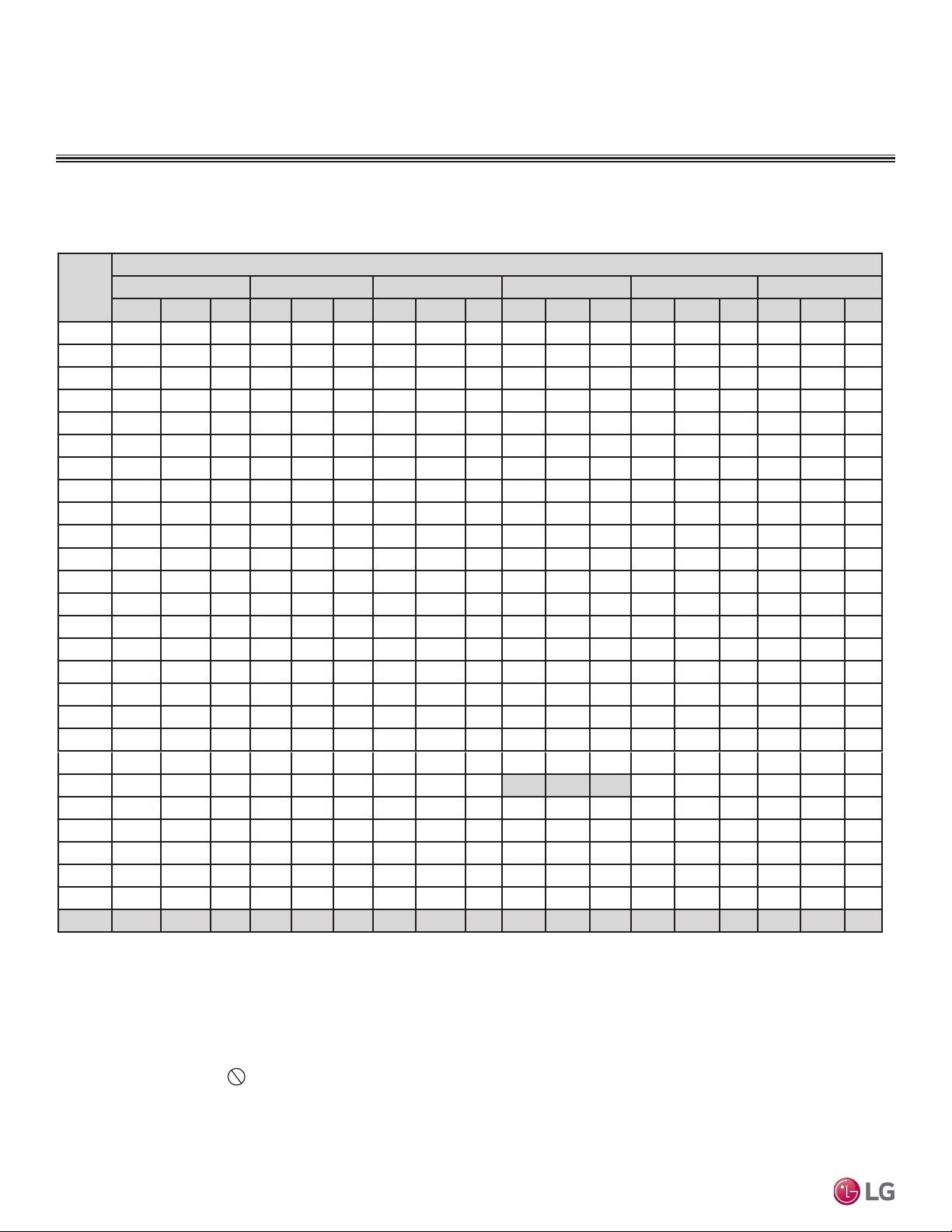
Due to our policy of continuous product innovation, some specications may change without notication.
©LG Electronics U.S.A., Inc., Englewood Cliffs, NJ. All rights reserved. “LG” is a registered trademark of LG Corp.
54 | PRODUCT DATA
Single Zone Vertical Air Handling Unit Engineering Manual
Table 28: Cooling Capacity Table for LUU368HV + LVN360HV4.
Cooling Capacity Table for LV360HV4 (LUU368HV + LVN360HV4)
Outdoor
Air
Temp.
(°F DB)
Indoor Air Temp. °F DB / °F WB
68 / 57 72 / 61 77 / 64 80 / 67 86 / 72 90 / 75
TC SHC PI TC SHC PI TC SHC PI TC SHC PI TC SHC PI TC SHC PI
-4 35.39 26.37 1.70 37.59 27.86 1.77 39.79 26.97 1.83 41.38 27.54 1.85 44.19 27.77 1.89 46.38 28.30 1.92
0 35.37 26.52 1.72 37.57 28.02 1.79 39.77 27.13 1.85 41.35 27.70 1.87 44.16 27.94 1.91 46.36 28.46 1.95
5 35.34 26.76 1.75 37.54 28.26 1.81 39.73 27.37 1.88 41.32 27.94 1.90 44.12 28.18 1.94 46.32 28.71 1.98
10 35.32 26.97 1.78 37.51 28.49 1.84 39.70 27.58 1.91 41.29 28.16 1.93 44.09 28.40 1.97 46.28 28.94 2.01
15 35.29 27.18 1.80 37.48 28.71 1.87 39.67 27.80 1.94 41.26 28.39 1.96 44.06 28.63 2.00 46.25 29.17 2.04
20 35.26 27.39 1.83 37.45 28.94 1.89 39.64 28.02 1.96 41.23 28.61 1.99 44.02 28.85 2.02 46.21 29.40 2.06
25 35.24 27.61 1.85 37.43 29.16 1.92 39.61 28.24 1.99 41.19 28.83 2.01 43.99 29.07 2.05 46.18 29.62 2.09
30 35.21 27.82 1.88 37.40 29.39 1.95 39.58 28.45 2.02 41.16 29.05 2.04 43.96 29.30 2.08 46.14 29.85 2.12
35 35.18 28.03 1.91 37.37 29.61 1.98 39.55 28.67 2.05 41.13 29.27 2.07 43.92 29.52 2.11 46.11 30.08 2.15
40 35.16 28.24 1.93 37.34 29.83 2.00 39.52 28.88 2.08 41.10 29.49 2.10 43.89 29.74 2.14 46.07 30.30 2.18
45 35.13 28.45 1.96 37.31 30.05 2.03 39.49 29.10 2.10 41.07 29.71 2.13 43.86 29.96 2.17 46.04 30.53 2.21
50 35.10 28.66 1.98 37.28 30.28 2.06 39.46 29.32 2.13 41.04 29.93 2.16 43.82 30.19 2.20 46.00 30.76 2.24
55 35.08 28.87 2.01 37.25 30.50 2.08 39.43 29.53 2.16 41.01 30.15 2.18 43.79 30.41 2.22 45.97 30.98 2.27
60 35.05 29.08 2.04 37.23 30.72 2.11 39.40 29.74 2.19 40.97 30.37 2.21 43.76 30.63 2.25 45.93 31.21 2.30
65 35.02 29.29 2.06 37.20 30.94 2.14 39.37 29.96 2.21 40.94 30.59 2.24 43.72 30.85 2.28 45.90 31.43 2.33
70 34.99 29.50 2.09 37.17 31.16 2.16 39.34 30.17 2.24 40.91 30.81 2.27 43.69 31.07 2.31 45.86 31.66 2.36
75 34.15 29.01 2.20 36.32 30.69 2.28 38.49 29.75 2.36 40.05 30.40 2.39 42.82 30.69 2.44 44.99 31.30 2.48
80 33.31 28.52 2.31 35.47 30.20 2.40 37.64 29.31 2.48 39.20 29.98 2.51 41.96 30.30 2.56 44.12 30.93 2.61
85 32.48 28.00 2.42 34.63 29.70 2.51 36.79 28.86 2.61 38.35 29.53 2.64 41.10 29.89 2.68 43.26 30.54 2.74
90 31.64 27.47 2.54 33.79 29.18 2.63 35.94 28.39 2.73 37.50 29.08 2.76 40.25 29.48 2.81 42.40 30.14 2.87
95 30.74 27.18 2.65 32.88 28.92 2.75 35.02 28.17 2.85 36.00 28.44 2.88 39.30 29.32 2.93 41.44 30.01 2.99
100 29.99 26.45 2.76 32.13 28.19 2.86 34.27 27.50 2.97 35.53 28.00 3.00 38.55 28.69 3.06 40.69 29.39 3.12
105 29.24 25.72 2.88 31.38 27.46 2.98 33.52 26.83 3.09 35.07 27.56 3.12 37.80 28.06 3.18 39.94 28.78 3.25
110 28.49 24.84 2.99 30.63 26.57 3.10 32.77 26.00 3.21 34.32 26.74 3.25 37.05 27.26 3.31 39.20 27.99 3.37
115 27.74 24.10 3.10 29.88 25.82 3.21 32.02 25.31 3.33 33.57 26.05 3.37 36.31 26.61 3.43 38.45 27.35 3.50
118 27.29 23.93 3.17 29.43 25.66 3.28 31.57 25.19 3.40 33.12 25.94 3.44 35.86 26.52 3.51 38.00 27.28 3.58
122 27.14 23.87 3.26 29.28 25.61 3.38 31.43 25.14 3.50 32.97 25.90 3.54 35.71 26.49 3.61 37.85 27.25 3.68
PERFORMANCE DATA
Cooling Capacity Tables
DB: Dry Bulb Temperature (°F) WB: Wet Bulb Temperature (°F) TC: Total Capacity
(kBtu/h)
SHC: Sensible Capacity (kBtu/h) PI: Power Input (kW) (includes compressor, indoor fan
motor and outdoor fan motor)
1. All capacities are net, evaporator fan motor heat is deducted.
2. Cooling operating range with the Low Ambient Baffle Kit (sold separately) is -4°F to
+122°F.
3. Grey shading indicates reference data. When operating the unit at this temperature,
these values can be different by discontinuous operation.
4. Direct interpolation is permissible.
Do not extrapolate.
Nominal capacity as rated: 0 ft. above sea level with 25 ft. of refrigerant piping.
0 ft. level difference between outdoor and indoor units.
Nominal cooling capacity rating obtained with air entering the indoor unit at 80ºF dry bulb
(DB) and 67ºF wet bulb (WB), and outdoor ambient conditions of 95ºF dry bulb (DB) and
75ºF wet bulb (WB).
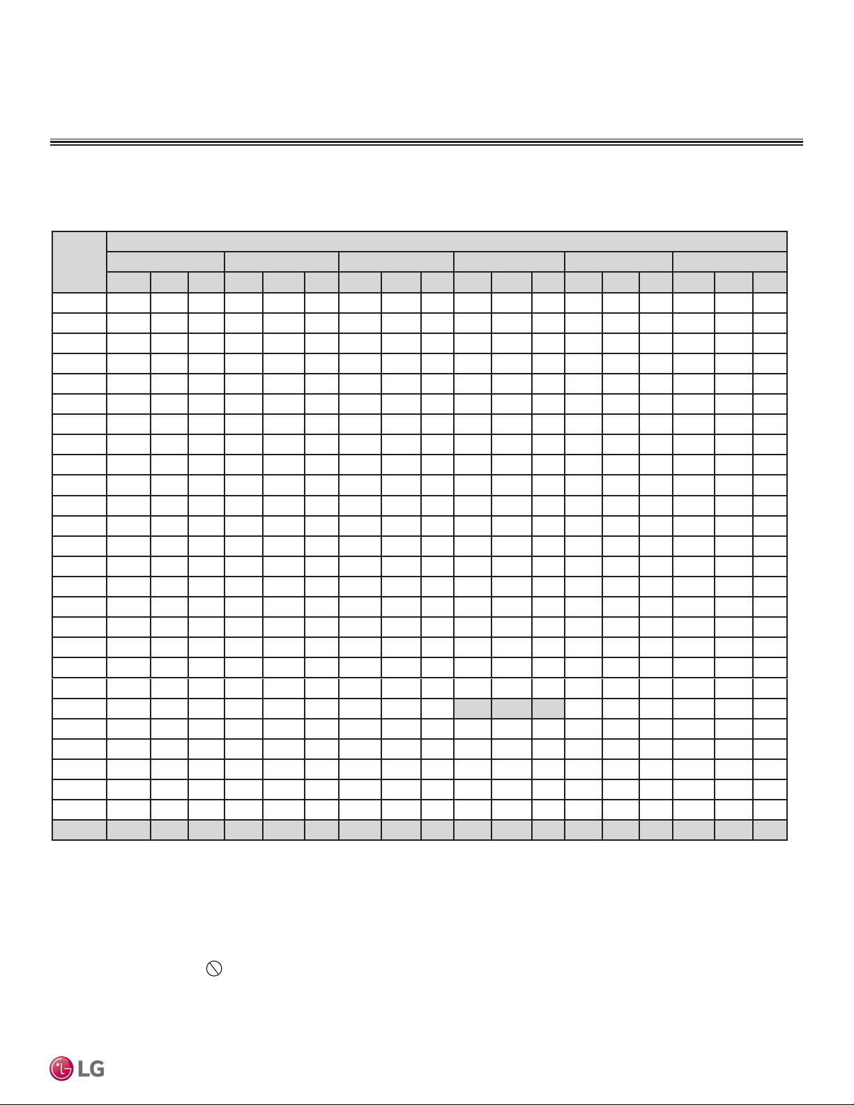
Due to our policy of continuous product innovation, some specications may change without notication.
©LG Electronics U.S.A., Inc., Englewood Cliffs, NJ. All rights reserved. “LG” is a registered trademark of LG Corp.
PRODUCT DATA | 55
Product Data
Table 29: Cooling Capacity Table for LUU428HV + LVN420HV.
Cooling Capacity Table for LV420HV (LUU428HV + LVN420HV)
Outdoor
Air
Temp.
(°F DB)
Indoor Air Temp. °F DB / °F WB
68 / 57 72 / 61 77 / 64 80 / 67 86 / 72 90 / 75
TC SHC PI TC SHC PI TC SHC PI TC SHC PI TC SHC PI TC SHC PI
-4 41.29 29.99 2.25 43.86 31.68 2.33 46.42 30.67 2.42 48.27 31.32 2.44 51.55 31.58 2.49 54.11 32.18 2.54
0 41.27 30.16 2.27 43.83 31.86 2.36 46.40 30.85 2.44 48.25 31.50 2.47 51.52 31.77 2.52 54.08 32.37 2.57
5 41.24 30.42 2.31 43.80 32.14 2.39 46.36 31.12 2.48 48.21 31.77 2.51 51.48 32.04 2.56 54.04 32.65 2.61
10 41.20 30.67 2.34 43.76 32.39 2.43 46.32 31.37 2.52 48.17 32.03 2.55 51.44 32.30 2.59 54.00 32.91 2.65
15 41.17 30.91 2.38 43.73 32.65 2.46 46.29 31.61 2.55 48.13 32.28 2.58 51.40 32.55 2.63 53.96 33.17 2.69
20 41.14 31.15 2.41 43.70 32.91 2.50 46.25 31.86 2.59 48.10 32.53 2.62 51.36 32.81 2.67 53.92 33.43 2.72
25 41.11 31.39 2.45 43.66 33.16 2.54 46.22 32.11 2.63 48.06 32.78 2.66 51.32 33.06 2.71 53.88 33.69 2.76
30 41.08 31.63 2.48 43.63 33.41 2.57 46.18 32.35 2.66 48.02 33.04 2.70 51.28 33.31 2.75 53.83 33.95 2.80
35 41.05 31.87 2.51 43.60 33.67 2.61 46.15 32.60 2.70 47.99 33.29 2.73 51.24 33.57 2.78 53.79 34.20 2.84
40 41.02 32.11 2.55 43.56 33.92 2.64 46.11 32.85 2.74 47.95 33.54 2.77 51.20 33.82 2.82 53.75 34.46 2.88
45 40.98 32.35 2.58 43.53 34.18 2.68 46.07 33.09 2.78 47.91 33.79 2.81 51.17 34.07 2.86 53.71 34.72 2.92
50 40.95 32.59 2.62 43.50 34.43 2.71 46.04 33.34 2.81 47.88 34.04 2.84 51.13 34.32 2.90 53.67 34.97 2.96
55 40.92 32.83 2.65 43.46 34.68 2.75 46.00 33.58 2.85 47.84 34.29 2.88 51.09 34.58 2.94 53.63 35.23 2.99
60 40.89 33.07 2.69 43.43 34.93 2.78 45.97 33.82 2.89 47.80 34.54 2.92 51.05 34.83 2.97 53.59 35.49 3.03
65 40.86 33.31 2.72 43.40 35.18 2.82 45.93 34.07 2.92 47.77 34.78 2.96 51.01 35.08 3.01 53.55 35.74 3.07
70 40.83 33.54 2.75 43.36 35.43 2.85 45.90 34.31 2.96 47.73 35.03 2.99 50.97 35.33 3.05 53.50 36.00 3.11
75 39.84 32.99 2.90 42.37 34.90 3.01 44.90 33.83 3.12 46.73 34.57 3.15 49.96 34.90 3.21 52.49 35.59 3.28
80 38.86 32.43 3.05 41.39 34.35 3.16 43.91 33.33 3.28 45.73 34.09 3.32 48.95 34.46 3.38 51.48 35.17 3.45
85 37.89 31.84 3.20 40.41 33.77 3.32 42.92 32.81 3.44 44.74 33.58 3.48 47.96 33.99 3.54 50.47 34.73 3.61
90 36.91 31.23 3.35 39.43 33.18 3.47 41.94 32.28 3.60 43.75 33.07 3.64 46.96 33.52 3.71 49.47 34.27 3.78
95 35.86 30.91 3.50 38.36 32.88 3.62 40.85 32.04 3.76 42.00 32.34 3.80 45.85 33.34 3.87 48.35 34.12 3.95
100 34.98 30.08 3.65 37.48 32.05 3.78 39.98 31.27 3.92 41.46 31.84 3.96 44.98 32.62 4.04 47.47 33.42 4.12
105 34.11 29.25 3.79 36.61 31.22 3.93 39.11 30.51 4.08 40.91 31.34 4.12 44.10 31.90 4.20 46.60 32.72 4.28
110 33.24 28.25 3.94 35.74 30.21 4.09 38.23 29.57 4.24 40.04 30.40 4.28 43.23 31.00 4.36 45.73 31.83 4.45
115 32.37 27.41 4.09 34.86 29.36 4.24 37.36 28.78 4.40 39.17 29.63 4.45 42.36 30.26 4.53 44.86 31.10 4.62
118 31.84 27.21 4.18 34.34 29.18 4.33 36.84 28.64 4.49 38.64 29.50 4.54 41.83 30.16 4.63 44.33 31.02 4.72
122 31.67 27.14 4.30 34.16 29.12 4.46 36.66 28.59 4.62 38.47 29.45 4.67 41.66 30.12 4.76 44.16 30.99 4.86
PERFORMANCE DATA
Cooling Capacity Tables
DB: Dry Bulb Temperature (°F) WB: Wet Bulb Temperature (°F) TC: Total Capacity
(kBtu/h)
SHC: Sensible Capacity (kBtu/h) PI: Power Input (kW) (includes compressor, indoor fan
motor and outdoor fan motor)
1. All capacities are net, evaporator fan motor heat is deducted.
2. Cooling operating range with the Low Ambient Baffle Kit (sold separately) is -4°F to
+122°F.
3. Grey shading indicates reference data. When operating the unit at this temperature,
these values can be different by discontinuous operation.
4. Direct interpolation is permissible.
Do not extrapolate.
Nominal capacity as rated: 0 ft. above sea level with 25 ft. of refrigerant piping.
0 ft. level difference between outdoor and indoor units.
Nominal cooling capacity rating obtained with air entering the indoor unit at 80ºF dry
bulb (DB) and 67ºF wet bulb (WB), and outdoor ambient conditions of 95ºF dry bulb
(DB) and 75ºF wet bulb (WB).
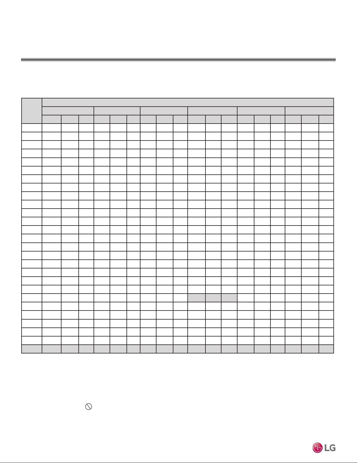
Due to our policy of continuous product innovation, some specications may change without notication.
©LG Electronics U.S.A., Inc., Englewood Cliffs, NJ. All rights reserved. “LG” is a registered trademark of LG Corp.
56 | PRODUCT DATA
Single Zone Vertical Air Handling Unit Engineering Manual
Table 30: Cooling Capacity Table for LUU488HV + LVN480HV.
Cooling Capacity Table for LV480HV (LUU488HV + LVN480HV)
Outdoor
Air
Temp.
(°F DB)
Indoor Air Temp. °F DB / °F WB
68 / 57 72 / 61 77 / 64 80 / 67 86 / 72 90 / 75
TC SHC PI TC SHC PI TC SHC PI TC SHC PI TC SHC PI TC SHC PI
-4 47.19 33.83 2.84 50.12 35.73 2.94 53.05 34.60 3.05 55.17 35.33 3.09 58.91 35.62 3.14 61.84 36.30 3.21
0 47.16 34.02 2.87 50.09 35.94 2.98 53.02 34.80 3.08 55.14 35.53 3.12 58.88 35.83 3.18 61.81 36.51 3.24
5 47.13 34.32 2.92 50.05 36.25 3.02 52.98 35.10 3.13 55.09 35.84 3.17 58.83 36.14 3.23 61.76 36.83 3.29
10 47.09 34.59 2.96 50.01 36.54 3.07 52.94 35.38 3.18 55.05 36.13 3.22 58.79 36.43 3.28 61.71 37.12 3.34
15 47.05 34.87 3.00 49.98 36.83 3.11 52.90 35.66 3.23 55.01 36.41 3.26 58.74 36.72 3.33 61.67 37.41 3.39
20 47.02 35.14 3.05 49.94 37.12 3.16 52.86 35.94 3.27 54.97 36.70 3.31 58.70 37.01 3.37 61.62 37.71 3.44
25 46.98 35.41 3.09 49.90 37.41 3.20 52.82 36.22 3.32 54.93 36.98 3.36 58.65 37.29 3.42 61.57 38.00 3.49
30 46.95 35.68 3.13 49.86 37.69 3.25 52.78 36.50 3.37 54.88 37.26 3.41 58.61 37.58 3.47 61.52 38.29 3.54
35 46.91 35.95 3.18 49.82 37.98 3.29 52.74 36.77 3.41 54.84 37.55 3.45 58.56 37.86 3.52 61.48 38.58 3.59
40 46.87 36.22 3.22 49.79 38.26 3.34 52.70 37.05 3.46 54.80 37.83 3.50 58.52 38.15 3.56 61.43 38.87 3.64
45 46.84 36.49 3.26 49.75 38.55 3.38 52.66 37.33 3.51 54.76 38.11 3.55 58.47 38.43 3.61 61.38 39.16 3.68
50 46.80 36.76 3.31 49.71 38.84 3.43 52.62 37.60 3.55 54.72 38.39 3.59 58.43 38.72 3.66 61.34 39.45 3.73
55 46.77 37.03 3.35 49.67 39.12 3.47 52.58 37.88 3.60 54.67 38.68 3.64 58.38 39.00 3.71 61.29 39.74 3.78
60 46.73 37.30 3.39 49.63 39.40 3.52 52.54 38.15 3.64 54.63 38.96 3.69 58.34 39.29 3.76 61.24 40.03 3.83
65 46.70 37.57 3.44 49.60 39.69 3.56 52.50 38.43 3.69 54.59 39.24 3.73 58.30 39.57 3.80 61.20 40.32 3.88
70 46.66 37.84 3.48 49.56 39.97 3.61 52.46 38.70 3.74 54.55 39.52 3.78 58.25 39.85 3.85 61.15 40.60 3.93
75 45.54 37.22 3.67 48.43 39.36 3.80 51.32 38.16 3.94 53.41 38.99 3.98 57.10 39.37 4.06 59.99 40.15 4.14
80 44.41 36.58 3.85 47.30 38.74 3.99 50.18 37.60 4.14 52.26 38.45 4.19 55.95 38.87 4.27 58.83 39.68 4.35
85 43.30 35.91 4.04 46.18 38.09 4.19 49.05 37.01 4.34 51.13 37.88 4.39 54.81 38.35 4.47 57.68 39.17 4.56
90 42.19 35.23 4.23 45.06 37.43 4.38 47.93 36.42 4.54 50.00 37.30 4.60 53.66 37.81 4.68 56.53 38.66 4.78
95 40.98 34.86 4.42 43.84 37.09 4.58 46.69 36.14 4.75 48.00 36.48 4.80 52.40 37.61 4.89 55.25 38.49 4.99
100 39.98 33.93 4.60 42.84 36.15 4.77 45.69 35.28 4.95 47.38 35.91 5.00 51.40 36.80 5.10 54.26 37.70 5.20
105 38.98 33.00 4.79 41.84 35.22 4.97 44.69 34.42 5.15 46.76 35.35 5.21 50.40 35.99 5.31 53.26 36.91 5.41
110 37.99 31.87 4.98 40.84 34.08 5.16 43.70 33.35 5.35 45.76 34.29 5.41 49.41 34.97 5.51 52.26 35.90 5.62
115 36.99 30.91 5.17 39.84 33.12 5.36 42.70 32.47 5.55 44.76 33.42 5.62 48.41 34.13 5.72 51.26 35.08 5.84
118 36.39 30.69 5.28 39.24 32.92 5.47 42.10 32.30 5.67 44.16 33.27 5.74 47.81 34.02 5.85 50.66 34.99 5.96
122 36.19 30.61 5.43 39.05 32.85 5.63 41.90 32.25 5.83 43.96 33.22 5.90 47.61 33.98 6.01 50.46 34.96 6.13
PERFORMANCE DATA
Cooling Capacity Tables
DB: Dry Bulb Temperature (°F) WB: Wet Bulb Temperature (°F) TC: Total Capacity
(kBtu/h)
SHC: Sensible Capacity (kBtu/h) PI: Power Input (kW) (includes compressor, indoor fan
motor and outdoor fan motor)
1. All capacities are net, evaporator fan motor heat is deducted.
2. Cooling operating range with the Low Ambient Baffle Kit (sold separately) is -4°F to
+122°F.
3. Grey shading indicates reference data. When operating the unit at this temperature,
these values can be different by discontinuous operation.
4. Direct interpolation is permissible.
Do not extrapolate.
Nominal capacity as rated: 0 ft. above sea level with 25 ft. of refrigerant piping.
0 ft. level difference between outdoor and indoor units.
Nominal cooling capacity rating obtained with air entering the indoor unit at 80ºF dry bulb
(DB) and 67ºF wet bulb (WB), and outdoor ambient conditions of 95ºF dry bulb (DB) and
75ºF wet bulb (WB).
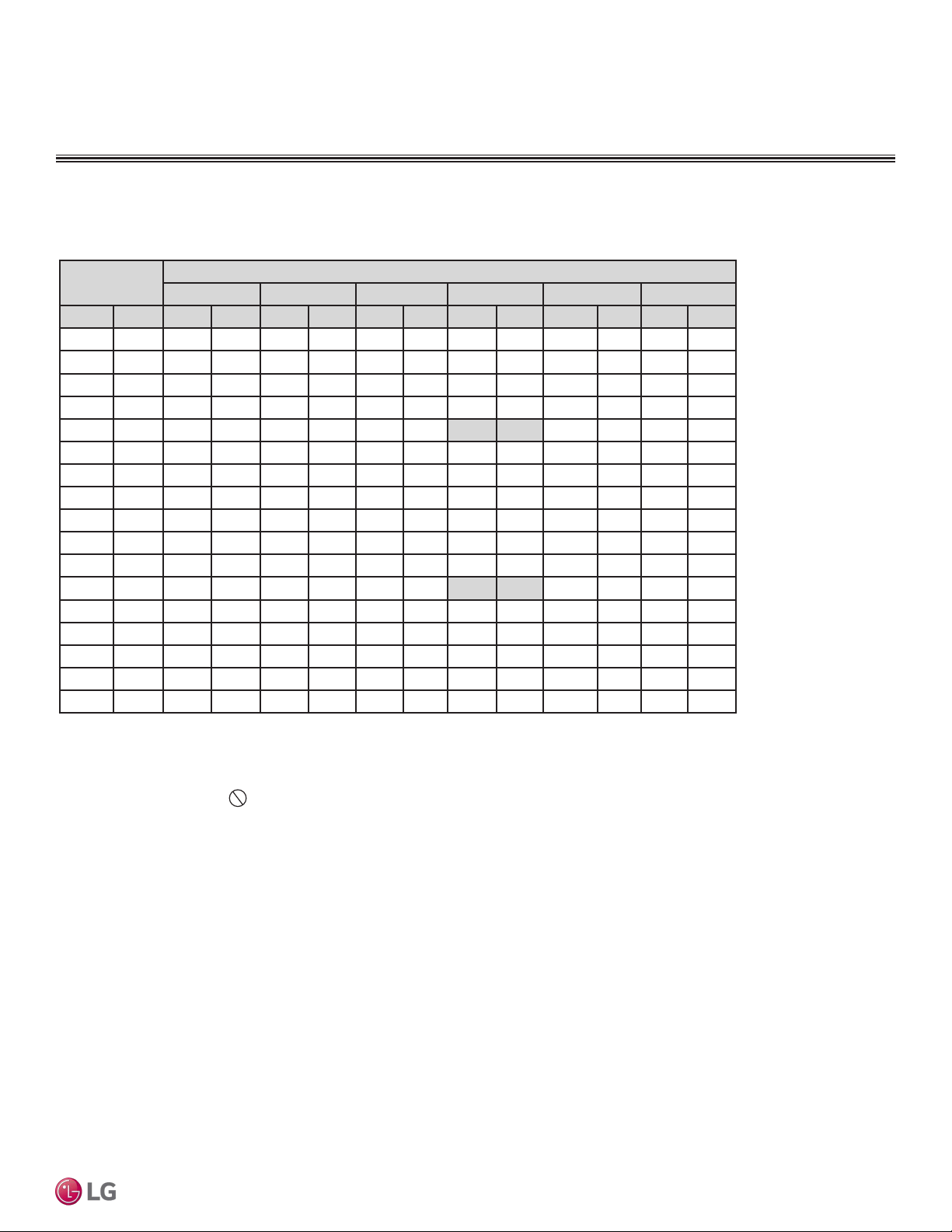
Due to our policy of continuous product innovation, some specications may change without notication.
©LG Electronics U.S.A., Inc., Englewood Cliffs, NJ. All rights reserved. “LG” is a registered trademark of LG Corp.
PRODUCT DATA | 57
Product Data
Table 31: Heating Capacity Table for LUU188HV + LVN180HV4.
Heating Capacity Table for LV180HV4 (LUU188HV + LVN180HV4)
Outdoor Air
Temp.
Indoor Air Temp.: °FDB
61.0 64.0 68.0 70.0 72.0 75.0
°F DB °F WB TC PI TC PI TC PI TC PI TC PI TC PI
-4 -4.4 7.66 1.26 7.08 1.31 7.05 1.32 6.97 1.33 6.90 1.34 6.59 1.39
0 -0.4 9.23 1.26 8.68 1.31 8.55 1.33 8.43 1.35 8.33 1.36 7.98 1.40
5 4.5 11.10 1.27 10.58 1.32 10.33 1.35 10.16 1.36 10.03 1.38 9.62 1.42
10 9 12.35 1.28 11.85 1.33 11.52 1.36 11.32 1.38 11.16 1.39 10.72 1.44
17 15 13.73 1.29 13.25 1.34 12.83 1.38 12.60 1.40 12.41 1.42 11.94 1.46
20 19 14.56 1.30 14.10 1.34 13.63 1.39 13.37 1.41 13.17 1.43 12.67 1.47
25 23 15.96 1.32 15.49 1.36 14.95 1.41 14.66 1.44 14.44 1.46 13.89 1.50
30 28 17.37 1.34 16.83 1.39 16.25 1.43 15.95 1.46 15.72 1.49 15.14 1.52
35 32 18.78 1.37 18.18 1.41 17.56 1.45 17.24 1.48 16.99 1.51 16.38 1.55
40 36 19.73 1.41 19.18 1.45 18.57 1.50 18.25 1.53 17.99 1.55 17.34 1.59
45 41 20.93 1.46 20.43 1.50 19.83 1.55 19.50 1.58 19.24 1.60 18.54 1.65
47 43 21.41 1.48 20.93 1.52 20.33 1.57 20.00 1.60 19.73 1.62 19.02 1.67
50 46 21.47 1.47 21.04 1.51 20.52 1.55 20.22 1.58 19.98 1.60 19.31 1.64
55 51 21.58 1.45 21.22 1.49 20.83 1.52 20.59 1.54 20.40 1.55 19.79 1.59
60 56 21.68 1.44 21.40 1.46 21.14 1.49 20.95 1.50 20.81 1.51 20.28 1.53
63 59 21.74 1.43 21.51 1.45 21.32 1.47 21.18 1.48 21.06 1.48 20.57 1.50
68 64 21.81 1.42 21.62 1.43 21.51 1.45 21.40 1.46 21.31 1.46 20.86 1.47
PERFORMANCE DATA
Heating Capacity Tables
DB: Dry Bulb Temperature (°F) WB: Wet Bulb Temperature (°F) TC: Total
Capacity (kBtu/h)
PI: Power Input (kW) (includes compressor, indoor fan motor, and outdoor
fan motor)
1. All capacities are net, evaporator fan motor heat is deducted.
2. Direct interpolation is permissible.
Do not extrapolate.
Nominal capacity as rated: 0 ft. above sea level with 25 ft. of refrigerant
piping.
0 ft. level difference between outdoor and indoor units.
Nominal heating capacity rating obtained with air entering the indoor
unit at 70ºF dry bulb (DB) and 60ºF wet bulb (WB), and outdoor ambient
conditions of 47ºF dry bulb (DB) and 43ºF wet bulb (WB).
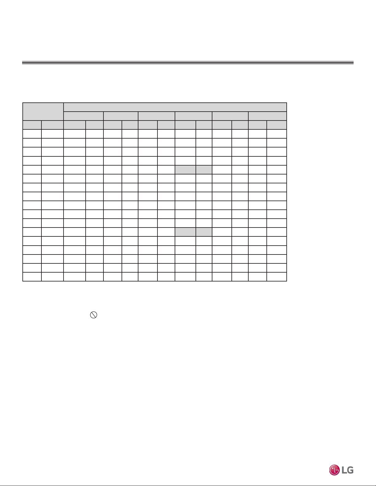
Due to our policy of continuous product innovation, some specications may change without notication.
©LG Electronics U.S.A., Inc., Englewood Cliffs, NJ. All rights reserved. “LG” is a registered trademark of LG Corp.
58 | PRODUCT DATA
Single Zone Vertical Air Handling Unit Engineering Manual
Table 32: Heating Capacity Table for LUU248HV + LVN240HV4.
Heating Capacity Table for LV240HV4 (LUU248HV + LVN240HV4)
Outdoor Air
Temp.
Indoor Air Temp.: °FDB
61.0 64.0 68.0 70.0 72.0 75.0
°F DB °F WB TC PI TC PI TC PI TC PI TC PI TC PI
-4 -4.4 12.73 1.64 11.85 1.71 11.74 1.73 11.60 1.74 11.48 1.75 10.98 1.81
0 -0.4 14.51 1.67 13.68 1.73 13.45 1.76 13.26 1.77 13.10 1.79 12.55 1.85
5 4.5 16.63 1.70 15.86 1.76 15.48 1.79 15.23 1.81 15.03 1.83 14.42 1.89
10 9 18.05 1.72 17.32 1.78 16.84 1.83 16.55 1.85 16.32 1.87 15.67 1.93
17 15 19.61 1.76 18.93 1.81 18.33 1.87 18.00 1.90 17.73 1.92 17.05 1.98
20 19 20.56 1.78 19.90 1.83 19.24 1.90 18.88 1.93 18.59 1.96 17.89 2.02
25 23 22.14 1.82 21.49 1.88 20.74 1.95 20.35 1.99 20.03 2.02 19.28 2.07
30 28 23.75 1.88 23.01 1.94 22.22 2.00 21.81 2.04 21.49 2.08 20.70 2.13
35 32 25.35 1.93 24.54 2.00 23.71 2.05 23.28 2.10 22.94 2.14 22.11 2.19
40 36 26.64 1.99 25.89 2.05 25.07 2.11 24.63 2.16 24.29 2.19 23.41 2.25
45 41 28.26 2.06 27.58 2.12 26.77 2.19 26.32 2.23 25.97 2.26 25.02 2.33
47 43 28.90 2.08 28.26 2.15 27.45 2.22 27.00 2.26 26.64 2.29 25.67 2.36
50 46 28.99 2.07 28.40 2.13 27.70 2.19 27.30 2.23 26.98 2.25 26.07 2.31
55 51 29.13 2.05 28.65 2.10 28.12 2.15 27.79 2.17 27.54 2.19 26.72 2.24
60 56 29.27 2.03 28.89 2.07 28.53 2.10 28.29 2.12 28.09 2.13 27.38 2.17
63 59 29.35 2.01 29.03 2.05 28.78 2.08 28.59 2.09 28.43 2.10 27.77 2.12
68 64 29.44 2.00 29.18 2.03 29.04 2.05 28.89 2.06 28.77 2.06 28.17 2.08
PERFORMANCE DATA
Heating Capacity Tables
DB: Dry Bulb Temperature (°F) WB: Wet Bulb Temperature (°F) TC:
Total Capacity (kBtu/h)
PI: Power Input (kW) (includes compressor, indoor fan motor, and
outdoor fan motor)
1. All capacities are net, evaporator fan motor heat is deducted.
2. Direct interpolation is permissible.
Do not extrapolate.
Nominal capacity as rated: 0 ft. above sea level with 25 ft. of refrigerant
piping.
0 ft. level difference between outdoor and indoor units.
Nominal heating capacity rating obtained with air entering the indoor
unit at 70ºF dry bulb (DB) and 60ºF wet bulb (WB), and outdoor ambi-
ent conditions of 47ºF dry bulb (DB) and 43ºF wet bulb (WB).
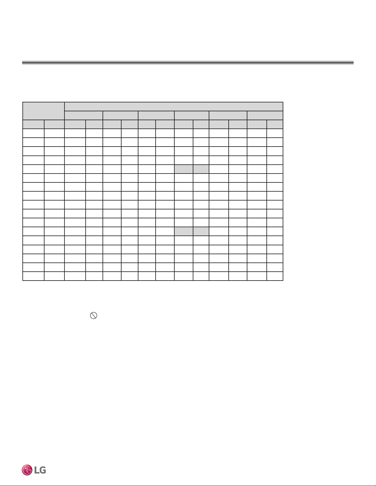
Due to our policy of continuous product innovation, some specications may change without notication.
©LG Electronics U.S.A., Inc., Englewood Cliffs, NJ. All rights reserved. “LG” is a registered trademark of LG Corp.
PRODUCT DATA | 59
Product Data
Table 33: Heating Capacity Table for LUU368HV + LVN360HV4.
Heating Capacity Table for LV360HV4 (LUU368HV + LVN360HV4)
Outdoor Air
Temp.
Indoor Air Temp.: °FDB
61.0 64.0 68.0 70.0 72.0 75.0
°F DB °F WB TC PI TC PI TC PI TC PI TC PI TC PI
-4 -4.4 16.28 2.30 15.09 2.39 15.00 2.41 14.82 2.43 14.68 2.44 14.02 2.53
0 -0.4 19.29 2.35 18.16 2.44 17.87 2.47 17.61 2.50 17.41 2.51 16.67 2.60
5 4.5 22.86 2.41 21.80 2.50 21.28 2.55 20.93 2.58 20.66 2.60 19.82 2.69
10 9 25.26 2.47 24.24 2.55 23.56 2.62 23.16 2.65 22.83 2.68 21.93 2.76
17 15 27.89 2.54 26.92 2.62 26.07 2.70 25.60 2.75 25.22 2.79 24.25 2.87
20 19 29.49 2.59 28.55 2.67 27.59 2.76 27.08 2.82 26.67 2.86 25.66 2.94
25 23 32.16 2.69 31.21 2.76 30.12 2.87 29.55 2.93 29.10 2.97 28.00 3.05
30 28 34.86 2.79 33.78 2.88 32.62 2.97 32.02 3.04 31.54 3.09 30.38 3.17
35 32 37.55 2.89 36.36 3.00 35.12 3.07 34.49 3.15 33.98 3.20 32.76 3.28
40 36 39.47 2.98 38.36 3.08 37.14 3.17 36.49 3.23 35.98 3.29 34.68 3.37
45 41 41.86 3.08 40.86 3.19 39.66 3.29 39.00 3.35 38.47 3.39 37.07 3.49
47 43 42.82 3.13 41.86 3.23 40.66 3.33 40.00 3.39 39.47 3.44 38.03 3.54
50 46 42.94 3.11 42.08 3.20 41.04 3.29 40.44 3.34 39.97 3.38 38.62 3.47
55 51 43.15 3.07 42.44 3.15 41.65 3.22 41.18 3.26 40.79 3.29 39.59 3.36
60 56 43.36 3.04 42.80 3.10 42.27 3.16 41.91 3.18 41.62 3.20 40.56 3.25
63 59 43.49 3.02 43.01 3.07 42.64 3.12 42.35 3.13 42.12 3.14 41.14 3.18
68 64 43.61 3.00 43.23 3.04 43.02 3.08 42.80 3.08 42.62 3.09 41.73 3.12
PERFORMANCE DATA
Heating Capacity Tables
DB: Dry Bulb Temperature (°F) WB: Wet Bulb Temperature (°F) TC:
Total Capacity (kBtu/h)
PI: Power Input (kW) (includes compressor, indoor fan motor, and
outdoor fan motor)
1. All capacities are net, evaporator fan motor heat is deducted.
2. Direct interpolation is permissible.
Do not extrapolate.
Nominal capacity as rated: 0 ft. above sea level with 25 ft. of refriger-
ant piping.
0 ft. level difference between outdoor and indoor units.
Nominal heating capacity rating obtained with air entering the indoor
unit at 70ºF dry bulb (DB) and 60ºF wet bulb (WB), and outdoor ambi-
ent conditions of 47ºF dry bulb (DB) and 43ºF wet bulb (WB).
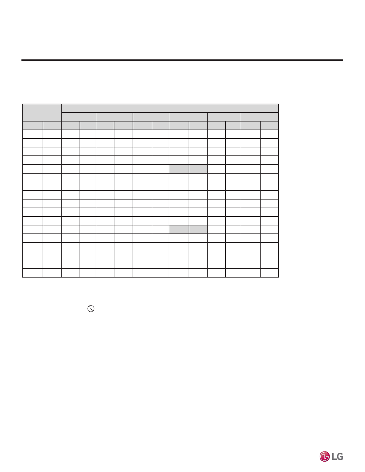
Due to our policy of continuous product innovation, some specications may change without notication.
©LG Electronics U.S.A., Inc., Englewood Cliffs, NJ. All rights reserved. “LG” is a registered trademark of LG Corp.
60 | PRODUCT DATA
Single Zone Vertical Air Handling Unit Engineering Manual
Table 34: Heating Capacity Table for LUU428HV + LVN420HV.
Heating Capacity Table for LV420HV (LUU428HV + LVN420HV)
Outdoor Air
Temp.
Indoor Air Temp.: °FDB
61.0 64.0 68.0 70.0 72.0 75.0
°F DB °F WB TC PI TC PI TC PI TC PI TC PI TC PI
-4 -4.4 20.39 2.80 18.93 2.91 18.79 2.95 18.57 2.97 18.38 2.98 17.57 3.09
0 -0.4 23.74 2.85 22.37 2.96 22.00 3.01 21.68 3.04 21.43 3.06 20.53 3.17
5 4.5 27.73 2.92 26.44 3.02 25.81 3.08 25.39 3.12 25.05 3.15 24.04 3.25
10 9 30.40 2.97 29.17 3.08 28.36 3.15 27.87 3.20 27.48 3.23 26.40 3.33
17 15 33.34 3.05 32.18 3.15 31.16 3.25 30.60 3.30 30.15 3.34 28.99 3.44
20 19 35.12 3.10 34.00 3.20 32.86 3.31 32.25 3.37 31.77 3.42 30.56 3.51
25 23 38.10 3.20 36.97 3.29 35.69 3.41 35.01 3.48 34.47 3.54 33.17 3.63
30 28 41.12 3.31 39.84 3.41 38.47 3.52 37.77 3.60 37.20 3.66 35.84 3.75
35 32 44.13 3.41 42.72 3.54 41.27 3.63 40.53 3.71 39.93 3.78 38.49 3.87
40 36 46.38 3.51 45.07 3.64 43.64 3.74 42.88 3.82 42.28 3.88 40.74 3.98
45 41 49.19 3.64 48.01 3.76 46.60 3.88 45.82 3.95 45.20 4.00 43.56 4.12
47 43 50.31 3.69 49.19 3.81 47.78 3.93 47.00 4.00 46.38 4.05 44.69 4.18
50 46 50.46 3.67 49.44 3.77 48.22 3.88 47.52 3.94 46.96 3.99 45.37 4.10
55 51 50.70 3.63 49.86 3.72 48.94 3.80 48.38 3.85 47.93 3.88 46.51 3.97
60 56 50.95 3.59 50.29 3.66 49.67 3.72 49.24 3.75 48.90 3.77 47.65 3.83
63 59 51.10 3.56 50.54 3.62 50.10 3.68 49.76 3.69 49.49 3.71 48.34 3.75
68 64 51.25 3.54 50.80 3.59 50.54 3.63 50.29 3.64 50.08 3.65 49.03 3.68
PERFORMANCE DATA
Heating Capacity Tables
DB: Dry Bulb Temperature (°F) WB: Wet Bulb Temperature (°F) TC:
Total Capacity (kBtu/h)
PI: Power Input (kW) (includes compressor, indoor fan motor, and
outdoor fan motor)
1. All capacities are net, evaporator fan motor heat is deducted.
2. Direct interpolation is permissible.
Do not extrapolate.
Nominal capacity as rated: 0 ft. above sea level with 25 ft. of refrigerant
piping.
0 ft. level difference between outdoor and indoor units.
Nominal heating capacity rating obtained with air entering the indoor
unit at 70ºF dry bulb (DB) and 60ºF wet bulb (WB), and outdoor ambi-
ent conditions of 47ºF dry bulb (DB) and 43ºF wet bulb (WB).
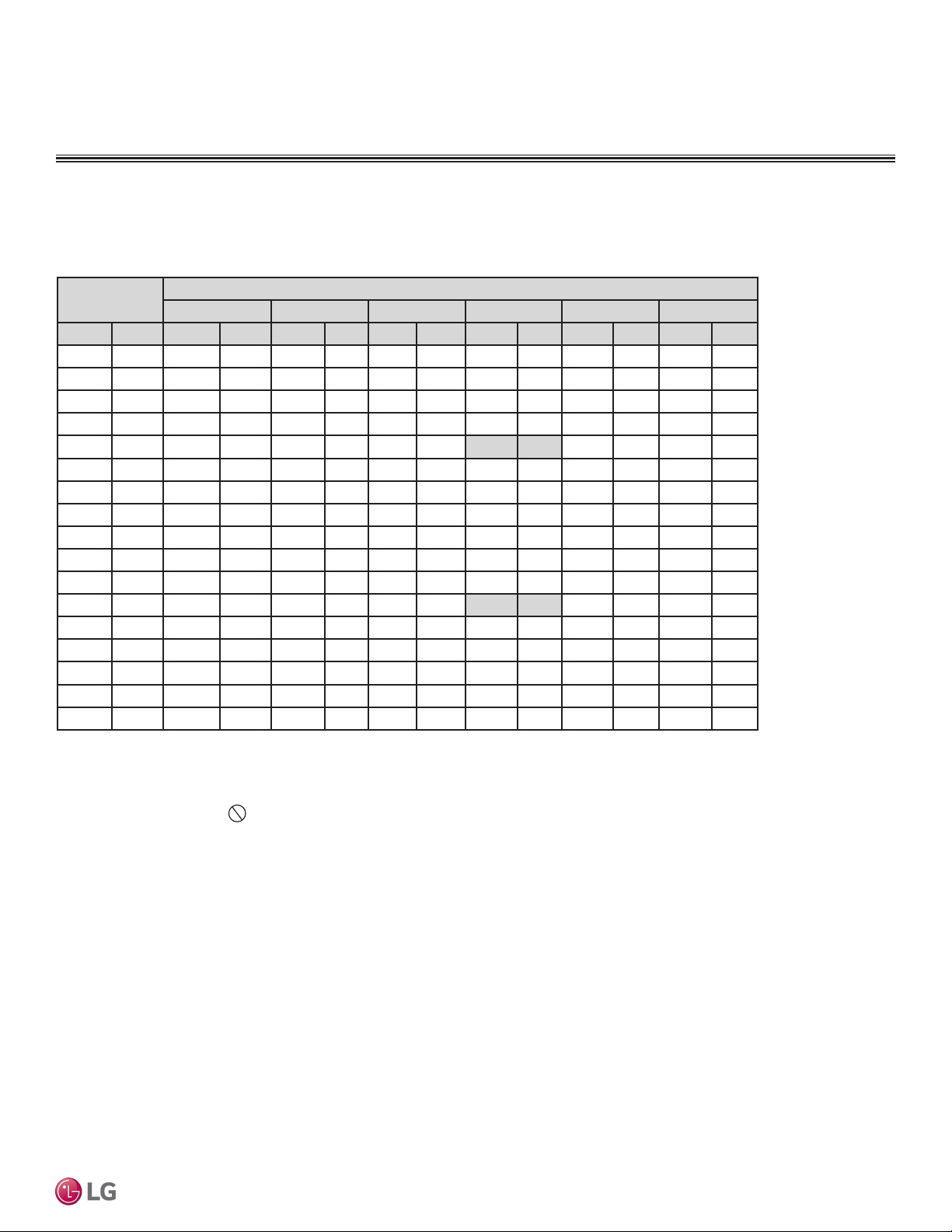
Due to our policy of continuous product innovation, some specications may change without notication.
©LG Electronics U.S.A., Inc., Englewood Cliffs, NJ. All rights reserved. “LG” is a registered trademark of LG Corp.
PRODUCT DATA | 61
Product Data
Table 35: Heating Capacity Table for LUU488HV + LVN480HV.
Heating Capacity Table for LV480HV (LUU488HV + LVN480HV)
Outdoor Air
Temp.
Indoor Air Temp.: °FDB
61.0 64.0 68.0 70.0 72.0 75.0
°F DB °F WB TC PI TC PI TC PI TC PI TC PI TC PI
-4 -4.4 25.60 3.39 23.81 3.53 23.61 3.57 23.32 3.59 23.08 3.61 22.07 3.74
0 -0.4 29.41 3.47 27.72 3.61 27.25 3.66 26.86 3.69 26.55 3.72 25.43 3.85
5 4.5 33.94 3.57 32.37 3.70 31.59 3.78 31.08 3.82 30.67 3.86 29.43 3.99
10 9 36.97 3.67 35.48 3.79 34.49 3.89 33.90 3.94 33.42 3.98 32.11 4.11
17 15 40.31 3.79 38.91 3.91 37.68 4.03 37.00 4.10 36.45 4.15 35.05 4.27
20 19 42.33 3.87 40.98 3.99 39.62 4.13 38.88 4.21 38.29 4.27 36.84 4.38
25 23 45.72 4.02 44.37 4.14 42.83 4.29 42.02 4.38 41.37 4.45 39.81 4.57
30 28 49.15 4.19 47.63 4.33 45.99 4.46 45.15 4.56 44.48 4.64 42.84 4.75
35 32 52.58 4.35 50.90 4.51 49.17 4.62 48.29 4.73 47.58 4.82 45.86 4.94
40 36 55.26 4.48 53.70 4.64 51.99 4.77 51.09 4.87 50.37 4.95 48.55 5.08
45 41 58.60 4.64 57.20 4.79 55.52 4.94 54.60 5.03 53.86 5.11 51.90 5.25
47 43 59.94 4.70 58.60 4.86 56.93 5.01 56.00 5.10 55.26 5.17 53.25 5.32
50 46 60.12 4.67 58.91 4.81 57.45 4.95 56.62 5.03 55.95 5.09 54.06 5.22
55 51 60.41 4.62 59.41 4.74 58.31 4.85 57.65 4.91 57.11 4.95 55.42 5.06
60 56 60.71 4.57 59.92 4.66 59.18 4.75 58.67 4.78 58.27 4.81 56.78 4.89
63 59 60.88 4.54 60.22 4.62 59.70 4.69 59.29 4.71 58.96 4.73 57.59 4.79
68 64 61.06 4.52 60.52 4.57 60.22 4.63 59.91 4.64 59.67 4.65 58.42 4.69
PERFORMANCE DATA
Heating Capacity Tables
DB: Dry Bulb Temperature (°F) WB: Wet Bulb Temperature (°F) TC: Total
Capacity (kBtu/h)
PI: Power Input (kW) (includes compressor, indoor fan motor, and outdoor
fan motor)
1. All capacities are net, evaporator fan motor heat is deducted.
2. Direct interpolation is permissible.
Do not extrapolate.
Nominal capacity as rated: 0 ft. above sea level with 25 ft. of refrigerant
piping.
0 ft. level difference between outdoor and indoor units.
Nominal heating capacity rating obtained with air entering the indoor unit
at 70ºF dry bulb (DB) and 60ºF wet bulb (WB), and outdoor ambient condi-
tions of 47ºF dry bulb (DB) and 43ºF wet bulb (WB).
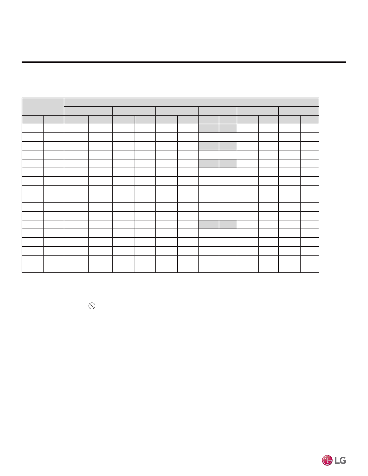
Due to our policy of continuous product innovation, some specications may change without notication.
©LG Electronics U.S.A., Inc., Englewood Cliffs, NJ. All rights reserved. “LG” is a registered trademark of LG Corp.
62 | PRODUCT DATA
Single Zone Vertical Air Handling Unit Engineering Manual
Outdoor Air
Temp.
Indoor Air Temp.: °FDB
61.0 64.0 68.0 70.0 72.0 75.0
°F DB °F WB TC PI TC PI TC PI TC PI TC PI TC PI
-4 -4.4 11.77 2.54 11.51 2.62 11.18 2.70 11.00 2.75 10.85 2.79 10.46 2.87
0 -0.4 14.15 2.43 13.84 2.51 13.44 2.59 13.22 2.64 13.05 2.67 12.57 2.76
5 4.5 17.13 2.31 16.74 2.38 16.27 2.46 16.00 2.50 15.79 2.53 15.21 2.61
10 9 18.04 2.20 17.64 2.27 17.14 2.34 16.86 2.38 16.63 2.42 16.03 2.49
17 15 19.61 2.13 18.93 2.19 18.33 2.26 18.00 2.30 17.73 2.33 17.05 2.40
20 19 19.93 2.06 19.30 2.13 18.65 2.20 18.31 2.24 18.03 2.27 17.34 2.34
25 23 20.47 1.97 19.87 2.03 19.18 2.10 18.81 2.14 18.52 2.18 17.83 2.24
30 28 21.04 1.88 20.38 1.94 19.68 2.00 19.32 2.05 19.03 2.08 18.33 2.13
35 32 21.59 1.79 20.91 1.86 20.19 1.90 19.83 1.95 19.54 1.98 18.83 2.03
40 36 22.69 1.84 22.06 1.91 21.35 1.96 20.98 2.00 20.69 2.04 19.94 2.09
45 41 24.07 1.91 23.49 1.97 22.80 2.04 22.42 2.07 22.12 2.10 21.32 2.16
47 43 24.62 1.94 24.07 2.00 23.38 2.06 23.00 2.10 22.69 2.13 21.87 2.19
50 46 24.69 1.92 24.19 1.98 23.60 2.04 23.25 2.07 22.98 2.09 22.20 2.15
55 51 24.81 1.90 24.40 1.95 23.95 2.00 23.68 2.02 23.46 2.04 22.76 2.08
60 56 24.93 1.88 24.61 1.92 24.31 1.96 24.10 1.97 23.93 1.98 23.32 2.01
63 59 25.01 1.87 24.73 1.90 24.52 1.93 24.35 1.94 24.22 1.95 23.65 1.97
68 64 25.08 1.86 24.86 1.88 24.73 1.91 24.61 1.91 24.51 1.91 23.99 1.93
Maximum Heating Capacity Table for LV180HV4 (LUU188HV + LVN180HV4)
Table 36: Maximum Heating Capacity Table for LUU188HV + LVN180HV4.
DB: Dry Bulb Temperature (°F) WB: Wet Bulb Temperature (°F) TC: Total Capacity
(kBtu/h)
PI: Power Input (kW) (includes compressor, indoor fan motor, and outdoor fan
motor)
1. All capacities are net, evaporator fan motor heat is deducted.
2. Direct interpolation is permissible.
Do not extrapolate.
Nominal capacity as rated: 0 ft. above sea level with 25 ft. of refrigerant piping.
0 ft. level difference between outdoor and indoor units.
Nominal heating capacity rating obtained with air entering the indoor unit at 70ºF
dry bulb (DB) and 60ºF wet bulb (WB), and outdoor ambient conditions of 47ºF dry
bulb (DB) and 43ºF wet bulb (WB).
PERFORMANCE DATA
Maximum Heating Capacity Tables
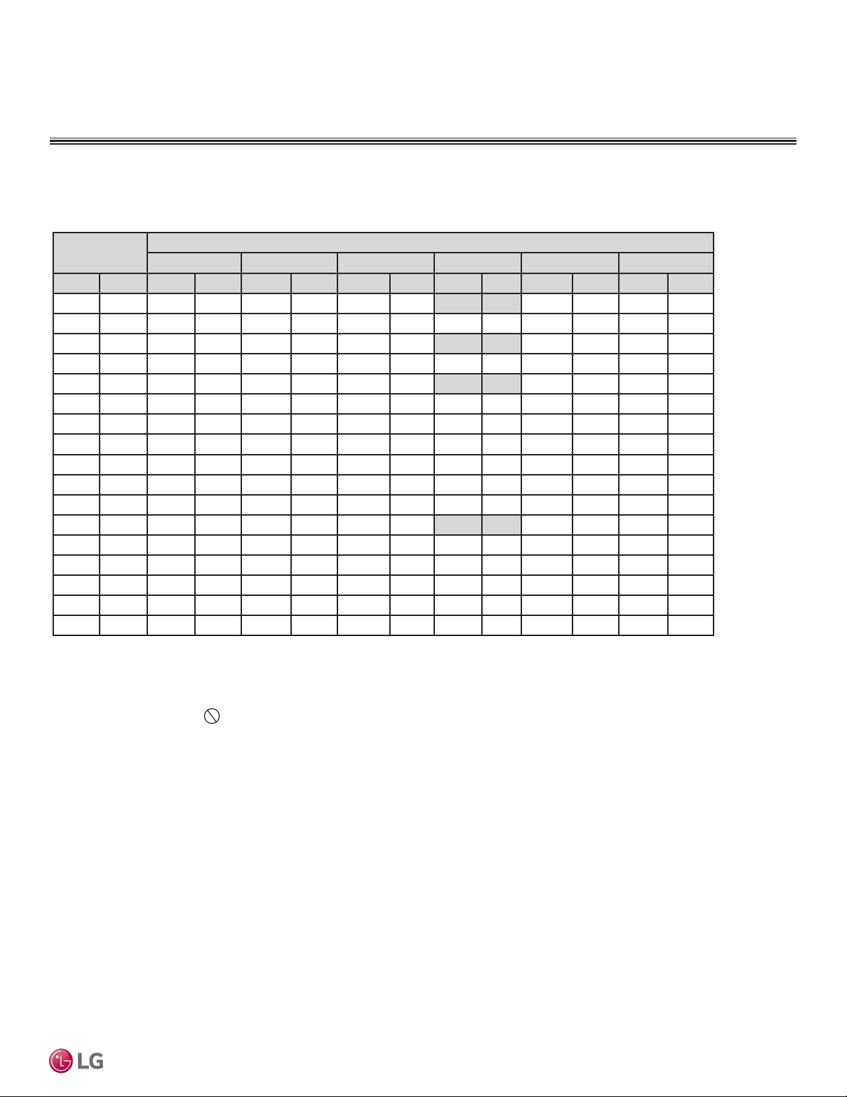
Due to our policy of continuous product innovation, some specications may change without notication.
©LG Electronics U.S.A., Inc., Englewood Cliffs, NJ. All rights reserved. “LG” is a registered trademark of LG Corp.
PRODUCT DATA | 63
Product Data
Table 37: Maximum Heating Capacity Table for LUU248HV + LVN240HV4.
Maximum Heating Capacity Table for LV240HV4 (LUU248HV + LVN240HV4)
Outdoor Air
Temp.
Indoor Air Temp.: °FDB
61.0 64.0 68.0 70.0 72.0 75.0
°F DB °F WB TC PI TC PI TC PI TC PI TC PI TC PI
-4 -4.4 16.06 3.04 15.70 3.14 15.25 3.24 15.00 3.30 14.80 3.34 14.26 3.44
0 -0.4 18.43 3.00 18.02 3.10 17.51 3.20 17.22 3.25 16.99 3.30 16.37 3.40
5 4.5 21.41 2.95 20.93 3.05 20.33 3.15 20.00 3.20 19.73 3.24 19.02 3.34
10 9 22.33 2.84 21.83 2.94 21.20 3.03 20.86 3.08 20.58 3.13 19.83 3.22
17 15 23.97 2.77 23.13 2.86 22.41 2.95 22.00 3.00 21.68 3.04 20.84 3.13
20 19 24.66 2.70 23.87 2.78 23.07 2.88 22.64 2.93 22.30 2.98 21.45 3.06
25 23 25.81 2.59 25.05 2.67 24.18 2.77 23.72 2.82 23.35 2.87 22.47 2.94
30 28 26.99 2.49 26.15 2.57 25.26 2.65 24.79 2.71 24.42 2.76 23.52 2.83
35 32 28.17 2.39 27.27 2.48 26.34 2.54 25.87 2.60 25.49 2.65 24.57 2.71
40 36 29.60 2.46 28.77 2.55 27.85 2.62 27.37 2.67 26.98 2.72 26.01 2.79
45 41 31.40 2.55 30.65 2.63 29.74 2.71 29.25 2.76 28.85 2.80 27.81 2.88
47 43 32.11 2.58 31.40 2.67 30.50 2.75 30.00 2.80 29.60 2.84 28.52 2.92
50 46 32.21 2.57 31.56 2.64 30.78 2.72 30.33 2.76 29.97 2.79 28.96 2.87
55 51 32.36 2.54 31.83 2.60 31.24 2.66 30.88 2.69 30.59 2.72 29.69 2.78
60 56 32.52 2.51 32.10 2.56 31.70 2.61 31.43 2.63 31.22 2.64 30.42 2.68
63 59 32.62 2.50 32.26 2.54 31.98 2.57 31.76 2.59 31.59 2.60 30.85 2.63
68 64 32.71 2.48 32.42 2.51 32.26 2.54 32.10 2.55 31.96 2.55 31.30 2.57
DB: Dry Bulb Temperature (°F) WB: Wet Bulb Temperature (°F) TC: Total
Capacity (kBtu/h)
PI: Power Input (kW) (includes compressor, indoor fan motor, and outdoor fan
motor)
1. All capacities are net, evaporator fan motor heat is deducted.
2. Direct interpolation is permissible.
Do not extrapolate.
Nominal capacity as rated: 0 ft. above sea level with 25 ft. of refrigerant piping.
0 ft. level difference between outdoor and indoor units.
Nominal heating capacity rating obtained with air entering the indoor unit at
70ºF dry bulb (DB) and 60ºF wet bulb (WB), and outdoor ambient conditions of
47ºF dry bulb (DB) and 43ºF wet bulb (WB).
PERFORMANCE DATA
Maximum Heating Capacity Tables
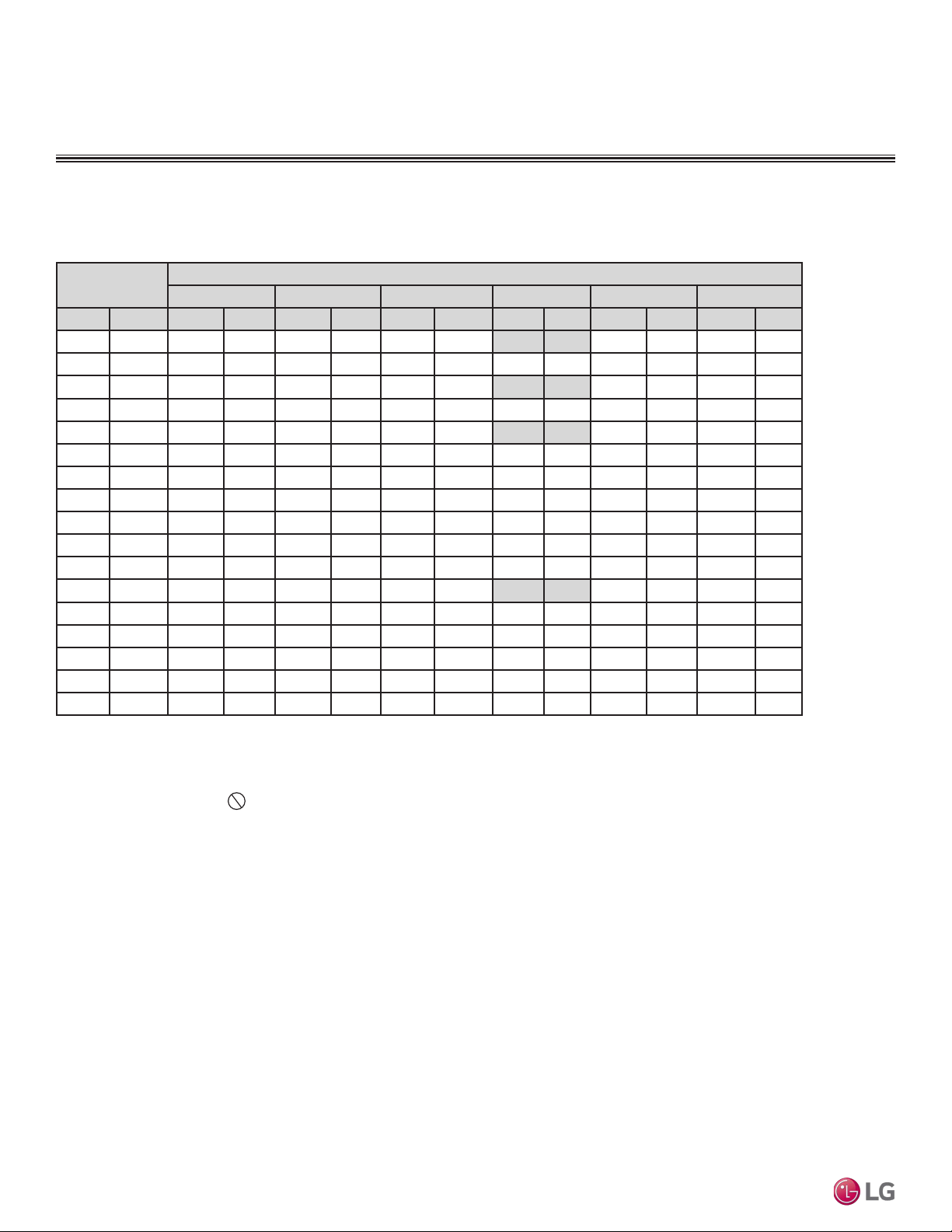
Due to our policy of continuous product innovation, some specications may change without notication.
©LG Electronics U.S.A., Inc., Englewood Cliffs, NJ. All rights reserved. “LG” is a registered trademark of LG Corp.
64 | PRODUCT DATA
Single Zone Vertical Air Handling Unit Engineering Manual
Outdoor Air
Temp.
Indoor Air Temp.: °FDB
61.0 64.0 68.0 70.0 72.0 75.0
°F DB °F WB TC PI TC PI TC PI TC PI TC PI TC PI
-4 -4.4 23.55 3.97 23.02 4.10 22.36 4.23 22.00 4.30 21.71 4.36 20.92 4.49
0 -0.4 27.35 4.01 26.74 4.14 25.98 4.27 25.55 4.35 25.22 4.41 24.30 4.54
5 4.5 32.11 4.06 31.40 4.19 30.50 4.33 30.00 4.40 29.60 4.46 28.52 4.59
10 9 33.03 4.11 32.29 4.25 31.37 4.38 30.86 4.46 30.45 4.52 29.34 4.65
17 15 34.86 4.16 33.65 4.29 32.59 4.43 32.00 4.50 31.53 4.56 30.32 4.69
20 19 36.39 4.17 35.23 4.30 34.05 4.45 33.42 4.53 32.92 4.60 31.66 4.72
25 23 38.95 4.21 37.79 4.33 36.48 4.49 35.79 4.58 35.24 4.66 33.91 4.78
30 28 41.54 4.26 40.25 4.40 38.87 4.53 38.16 4.63 37.59 4.71 36.20 4.83
35 32 44.13 4.31 42.72 4.46 41.27 4.58 40.53 4.69 39.93 4.77 38.49 4.89
40 36 46.38 4.44 45.07 4.59 43.64 4.72 42.88 4.82 42.28 4.90 40.74 5.03
45 41 49.19 4.59 48.01 4.75 46.60 4.89 45.82 4.98 45.20 5.06 43.56 5.20
47 43 50.31 4.66 49.19 4.81 47.78 4.96 47.00 5.05 46.38 5.12 44.69 5.27
50 46 50.46 4.63 49.44 4.77 48.22 4.90 47.52 4.98 46.96 5.04 45.37 5.17
55 51 50.70 4.58 49.86 4.69 48.94 4.80 48.38 4.86 47.93 4.90 46.51 5.01
60 56 50.95 4.53 50.29 4.62 49.67 4.70 49.24 4.74 48.90 4.77 47.65 4.84
63 59 51.10 4.50 50.54 4.57 50.10 4.64 49.76 4.66 49.49 4.68 48.34 4.74
68 64 51.25 4.47 50.80 4.53 50.54 4.58 50.29 4.59 50.08 4.60 49.03 4.64
Table 38: Maximum Heating Capacity Table for LUU368HV + LVN360HV4.
Maximum Heating Capacity Table for LV360HV4 (LUU368HV + LVN360HV4)
DB: Dry Bulb Temperature (°F) WB: Wet Bulb Temperature (°F) TC: Total
Capacity (kBtu/h)
PI: Power Input (kW) (includes compressor, indoor fan motor, and outdoor fan
motor)
1. All capacities are net, evaporator fan motor heat is deducted.
2. Direct interpolation is permissible.
Do not extrapolate.
Nominal capacity as rated: 0 ft. above sea level with 25 ft. of refrigerant piping.
0 ft. level difference between outdoor and indoor units.
Nominal heating capacity rating obtained with air entering the indoor unit at 70ºF
dry bulb (DB) and 60ºF wet bulb (WB), and outdoor ambient conditions of 47ºF
dry bulb (DB) and 43ºF wet bulb (WB).
PERFORMANCE DATA
Maximum Heating Capacity Tables
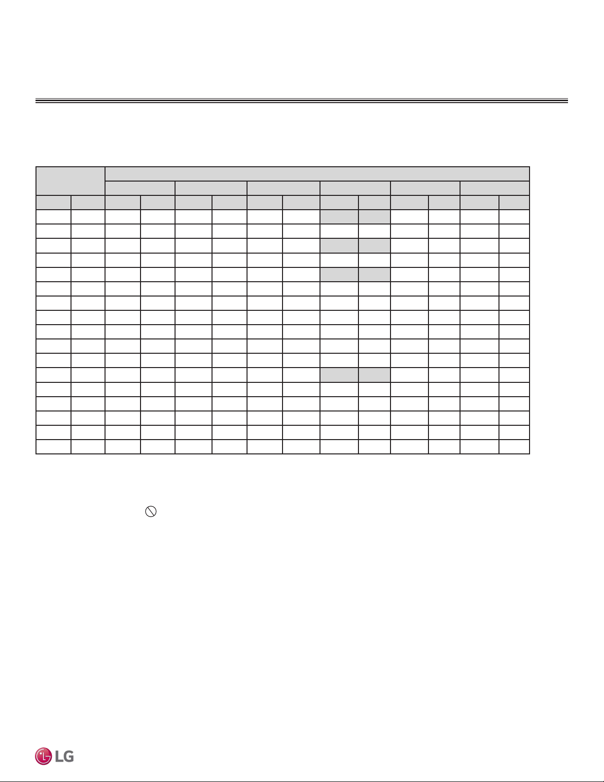
Due to our policy of continuous product innovation, some specications may change without notication.
©LG Electronics U.S.A., Inc., Englewood Cliffs, NJ. All rights reserved. “LG” is a registered trademark of LG Corp.
PRODUCT DATA | 65
Product Data
Outdoor Air
Temp.
Indoor Air Temp.: °FDB
61.0 64.0 68.0 70.0 72.0 75.0
°F DB °F WB TC PI TC PI TC PI TC PI TC PI TC PI
-4 -4.4 25.69 4.33 25.12 4.48 24.40 4.62 24.00 4.70 23.68 4.76 22.82 4.91
0 -0.4 29.50 4.37 28.84 4.52 28.01 4.66 27.56 4.74 27.19 4.81 26.20 4.95
5 4.5 34.25 4.43 33.49 4.57 32.53 4.72 32.00 4.80 31.57 4.87 30.43 5.01
10 9 36.55 4.53 35.73 4.68 34.71 4.83 34.14 4.92 33.69 4.98 32.46 5.13
17 15 40.31 4.62 38.91 4.77 37.68 4.92 37.00 5.00 36.45 5.07 35.05 5.21
20 19 42.18 4.64 40.83 4.78 39.47 4.95 38.74 5.04 38.15 5.11 36.70 5.26
25 23 45.31 4.69 43.96 4.82 42.44 5.01 41.63 5.11 40.99 5.19 39.45 5.33
30 28 48.47 4.76 46.97 4.91 45.36 5.06 44.53 5.18 43.86 5.26 42.25 5.40
35 32 51.64 4.82 49.99 4.99 48.29 5.12 47.42 5.24 46.73 5.34 45.04 5.47
40 36 54.27 4.96 52.74 5.14 51.06 5.28 50.18 5.39 49.47 5.48 47.68 5.62
45 41 57.56 5.14 56.18 5.31 54.53 5.48 53.62 5.58 52.90 5.66 50.98 5.82
47 43 58.87 5.21 57.56 5.38 55.91 5.55 55.00 5.65 54.27 5.73 52.30 5.90
50 46 59.05 5.18 57.86 5.33 56.42 5.49 55.61 5.57 54.95 5.64 53.10 5.79
55 51 59.33 5.12 58.35 5.25 57.27 5.37 56.62 5.43 56.09 5.48 54.43 5.60
60 56 59.62 5.07 58.85 5.17 58.12 5.26 57.63 5.30 57.23 5.33 55.76 5.41
63 59 59.80 5.03 59.14 5.12 58.63 5.19 58.23 5.22 57.91 5.24 56.56 5.30
68 64 59.97 5.00 59.44 5.07 59.15 5.13 58.84 5.14 58.60 5.15 57.38 5.19
Table 39: Maximum Heating Capacity Table for LUU428HV + LVN420HV.
Maximum Heating Capacity Table for LV420HV (LUU428HV + LVN420HV)
DB: Dry Bulb Temperature (°F) WB: Wet Bulb Temperature (°F) TC: Total Capacity
(kBtu/h)
PI: Power Input (kW) (includes compressor, indoor fan motor, and outdoor fan
motor)
1. All capacities are net, evaporator fan motor heat is deducted.
2. Direct interpolation is permissible.
Do not extrapolate.
Nominal capacity as rated: 0 ft. above sea level with 25 ft. of refrigerant piping.
0 ft. level difference between outdoor and indoor units.
Nominal heating capacity rating obtained with air entering the indoor unit at 70ºF
dry bulb (DB) and 60ºF wet bulb (WB), and outdoor ambient conditions of 47ºF dry
bulb (DB) and 43ºF wet bulb (WB).
PERFORMANCE DATA
Maximum Heating Capacity Tables

Due to our policy of continuous product innovation, some specications may change without notication.
©LG Electronics U.S.A., Inc., Englewood Cliffs, NJ. All rights reserved. “LG” is a registered trademark of LG Corp.
66 | PRODUCT DATA
Single Zone Vertical Air Handling Unit Engineering Manual
Outdoor Air
Temp.
Indoor Air Temp.: °FDB
61.0 64.0 68.0 70.0 72.0 75.0
°F DB °F WB TC PI TC PI TC PI TC PI TC PI TC PI
-4 -4.4 27.83 4.71 27.21 4.86 26.43 5.02 26.00 5.10 25.65 5.17 24.72 5.33
0 -0.4 31.64 4.77 30.93 4.92 30.05 5.08 29.56 5.17 29.16 5.24 28.10 5.40
5 4.5 36.39 4.84 35.58 5.00 34.56 5.16 34.00 5.25 33.55 5.32 32.33 5.48
10 9 39.15 4.92 38.27 5.08 37.18 5.25 36.57 5.34 36.09 5.41 34.77 5.57
17 15 43.58 4.99 42.06 5.15 40.74 5.31 40.00 5.40 39.41 5.47 37.89 5.63
20 19 45.68 5.00 44.23 5.15 42.75 5.33 41.96 5.43 41.32 5.51 39.75 5.66
25 23 49.21 5.02 47.75 5.17 46.09 5.37 45.22 5.47 44.52 5.56 42.84 5.71
30 28 52.77 5.07 51.14 5.24 49.38 5.40 48.47 5.52 47.75 5.62 45.99 5.76
35 32 56.33 5.12 54.54 5.30 52.68 5.44 51.73 5.57 50.98 5.67 49.13 5.81
40 36 59.20 5.27 57.54 5.45 55.70 5.61 54.74 5.73 53.97 5.82 52.01 5.97
45 41 62.79 5.46 61.29 5.64 59.48 5.82 58.50 5.92 57.71 6.01 55.61 6.18
47 43 64.23 5.53 62.79 5.72 61.00 5.90 60.00 6.00 59.20 6.08 57.05 6.26
50 46 64.41 5.50 63.12 5.66 61.55 5.83 60.66 5.91 59.95 5.98 57.92 6.15
55 51 64.73 5.44 63.66 5.57 62.48 5.71 61.76 5.77 61.19 5.82 59.38 5.95
60 56 65.04 5.38 64.20 5.49 63.41 5.59 62.86 5.63 62.43 5.66 60.83 5.75
63 59 65.23 5.35 64.52 5.43 63.96 5.51 63.53 5.54 63.18 5.56 61.71 5.63
68 64 65.42 5.31 64.85 5.38 64.52 5.44 64.19 5.46 63.93 5.47 62.59 5.51
Table 40: Maximum Heating Capacity Table for LUU488HV + LVN480HV.
Maximum Heating Capacity Table for LV480HV (LUU488HV + LVN480HV)
DB: Dry Bulb Temperature (°F) WB: Wet Bulb Temperature (°F) TC: Total
Capacity (kBtu/h)
PI: Power Input (kW) (includes compressor, indoor fan motor, and outdoor fan
motor)
1. All capacities are net, evaporator fan motor heat is deducted.
2. Direct interpolation is permissible.
Do not extrapolate.
Nominal capacity as rated: 0 ft. above sea level with 25 ft. of refrigerant piping.
0 ft. level difference between outdoor and indoor units.
Nominal heating capacity rating obtained with air entering the indoor unit at 70ºF
dry bulb (DB) and 60ºF wet bulb (WB), and outdoor ambient conditions of 47ºF
dry bulb (DB) and 43ºF wet bulb (WB).
PERFORMANCE DATA
Maximum Heating Capacity Tables
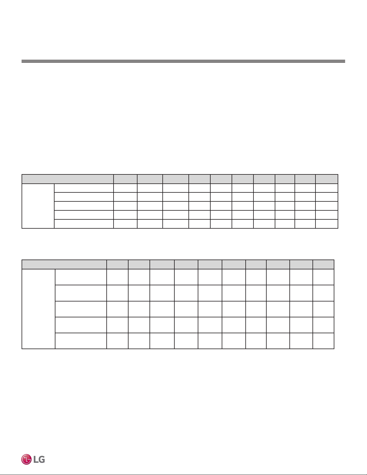
Due to our policy of continuous product innovation, some specications may change without notication.
©LG Electronics U.S.A., Inc., Englewood Cliffs, NJ. All rights reserved. “LG” is a registered trademark of LG Corp.
PRODUCT DATA | 67
Product Data
Correction Factors
Piping Length (ft.) 24.6 32.8 49.2 65.6 98.4 131.2 164 196.9 229.7 246
Rate of
Capacity
Change (%)
LUU188HV (18,000 Btu/h) 100 99.3 97.9 96.6 93.8 91.1 88.4 - - -
LUU248HV (24,000 Btu/h) 100 99.3 97.9 96.6 93.8 91.1 88.4 - - -
LUU368HV (36,000 Btu/h) 100 99.3 97.9 96.6 93.8 91.1 88.4 85.6 82.9 81.5
LUU428HV (42,000 Btu/h) 100 99.3 97.9 96.6 93.8 91.1 88.4 85.6 82.9 81.5
LUU488HV (48,000 Btu/h) 100 99.3 97.9 96.6 93.8 91.1 88.4 85.6 82.9 81.5
Cooling / Heating Correction Factors
For Single Zone Vertical Air Handling Unit systems, calculate the equivalent length of the liquid line from the outdoor unit to the indoor unit.
Also, determine the elevation difference of the indoor unit above or below the outdoor unit. Find corresponding cooling or heating capacity
correction factors as shown below. Multiply the correction factors by the cooling or heating capacity obtained from the capacity table using
design conditions. The result is the NET cooling or heating capacity.
Refrigerant Line Length Derates
For air-cooled systems, a capacity correction factor may have to be applied to account for the length of the system’s refrigerant pipe. Rate of
change in capacity due to increased piping lengths is shown below.
Cooling Capacity Coefficient Factors
Table 41: Vertical Air Handling Unit Cooling Capacity Coefcient Factors.
Heating Capacity Coefficient Factors
Table 42: Vertical Air Handling Unit Heating Capacity Coefcient Factors.
Piping Length (ft.) 24.6 32.8 49.2 65.6 98.4 131.2 164 196.9 229.7 246
Rate of
Capacity
Change (%)
LUU188HV (18,000
Btu/h)
100 99.3 97.9 96.6 93.8 91.1 88.4 - - -
LUU248HV (24,000
Btu/h)
100 99.3 97.9 96.6 93.8 91.1 88.4 - - -
LUU368HV (36,000
Btu/h)
100 99.7 99.2 98.7 97.7 96.6 95.6 94.6 93.5 93.0
LUU428HV (42,000
Btu/h)
100 99.7 99.2 98.7 97.7 96.6 95.6 94.6 93.5 93.0
LUU488HV (48,000
Btu/h)
100 99.7 99.2 98.7 97.7 96.6 95.6 94.6 93.5 93.0
EQUIPMENT SELECTION PROCEDURE
Due to our policy of continuous product innovation, some specications may change without notication.
©LG Electronics U.S.A., Inc., Englewood Cliffs, NJ. All rights reserved. “LG” is a registered trademark of LG Corp.
68 | PRODUCT DATA
Single Zone Vertical Air Handling Unit Engineering Manual
Equivalent Piping Length for Piping Components
Component Size (Inches)
Elbow (ft.)
1/4 3/8 1/2 5/8 3/4 7/8 1 1-1/8 1-1/4 1-3/8 1-1/2 1-5/8 1-3/4 2-1/8
0.5 0.6 0.7 0.8 1.2 1.3 1.5 1.6 1.8 2.0 2.1 2.3 2.5 2.8
Table 43: Equivalent Piping Length for Elbows.
Altitude Correction Factor
The impact of air density must be considered on systems installed at a significant altitude above sea level, therefore, locally accepted
altitude correction factors must be applied.
Table 44: Outdoor Unit Frost Accumulation Factor (Heating)
1
.
There will be a temporary reduction in capacity when frost / ice accumulates on the outside surface of the outdoor unit heat exchanger. The level of
capacity reduction depends on a number of factors, for example, outdoor temperature (°F DB), relative humidity (RH), and the amount of frost present.
Entering DB (ºF)
19.4 23.0 26.6 32.0 37.4 41.0 44.6
Derate factor
0.98 0.95 0.93 0.86 0.93 0.96 1.0
1
At 85% outdoor air relative humidity.
The frost accumulation factor does not account for effects of snow accumulation restricting airflow
through the outdoor unit coil.
Defrost Correction Factor for Heating Operation
The outdoor unit heating capacity may need to be adjusted for frost accumulation on air-cooled systems. If design day conditions are below
the dewpoint of the surrounding air, frost may not be a problem and no correction factor is needed. In certain weather conditions, however,
frost may form and accumulate on the air-cooled outdoor unit coil and impact the coils ability to transfer heat. If significant frost accumulates
on the outdoor unit coil, a defrost algorithm will start automatically. The timing between defrost periods is determined by the system’s ability
to achieve a target head pressure value.
Capacity and AHRI ratings tables do not factor in capacity reduction when frost has accumulated on the condenser coil, nor during defrost
operation.
Integrated heating capacity values can be obtained using the formula:
A = B x C
Where:
A = Integrated Heating Capacity.
B = Value found in the Capacity Table.
C = Correction Factor for Frost Accumulation Factor (from table at right).
Correction Factors
EQUIPMENT SELECTION PROCEDURE

Due to our policy of continuous product innovation, some specications may change without notication.
©LG Electronics U.S.A., Inc., Englewood Cliffs, NJ. All rights reserved. “LG” is a registered trademark of LG Corp.
PRODUCT DATA | 69
Product Data
Check the Indoor and Outdoor Unit Selection(s)
Compare the corrected cooling and heating capacities to the load calculations. Is each capacity sufficient for the zone it serves?
For each indoor unit, the corrected capacity must be at least equal to the total of the cooling design load (plus ventilation load, if applicable)
for the space served by the indoor unit. For each indoor unit, the corrected capacity also must be at least equal to the total of the heating
design load (plus ventilation load, if applicable) for the space(s) and / or thermal zones served by the indoor unit.
The outdoor unit selected must be large enough to offset the total cooling load for all spaces it serves (account for ventilation air cooling
load if the ventilation air has not been pretreated to room neutral conditions). The outdoor unit must also be large enough to offset the total
heating load for all spaces it serves.
If the corrected heating capacity ratio exceeds 100%, reselect the equipment, or change the system design by moving some of the load to
another system.
• Understand the design safety factors.
• Reference load calculations for actual cooling and heating capacities (applies in 99% of applications – consider total load when latent load
is greater than 30%).
• Verify that the sensible load of the zone is satisfied.
• Use caution when sizing to meet listed capacity specifications for the scheduled manufacturer’s equipment.
If further system design assistance is needed, or you have a unique application you would like to discuss, contact your LG sales rep.
1. Outdoor Unit Rated Capacity.
Q
odu(rated)
(From capacity tables).
2. Outdoor Unit Capacity at Ti, To Temperature.
Q
odu(Ti, To)
(From capacity tables).
3 Outdoor Unit Capacity Coefficient Factor.
F
(Ti, To)
= Q
odu(Ti, To)
/ Q
odu(rated)
4. Piping Correction Factor (From Capacity Coefficient
Factor Tables).
F
(length)
for each piping length
5. Individual Indoor Unit Combination Capacity.
Q
idu (combi)
= Q
odu(rated)
x Q
idu(rated)
/ Q
idu(rated-total)
6. Individual Indoor Unit Actual Capacity.
Q
idu (actual)
= Q
odu(combi)
x F
(Ti, To)
x F
(length, altitude)
System Sizing Check Formulas
Conclusions and Recommendations
EQUIPMENT SELECTION PROCEDURE

“Placement Considerations” on page 71
“Clearances” on page 75
“Installing Outdoor Units Indoors” on page 78
“Refrigerant Piping Design” on page 80
VERTICAL AIR HANDLING
UNIT APPLICATION
GUIDELINES
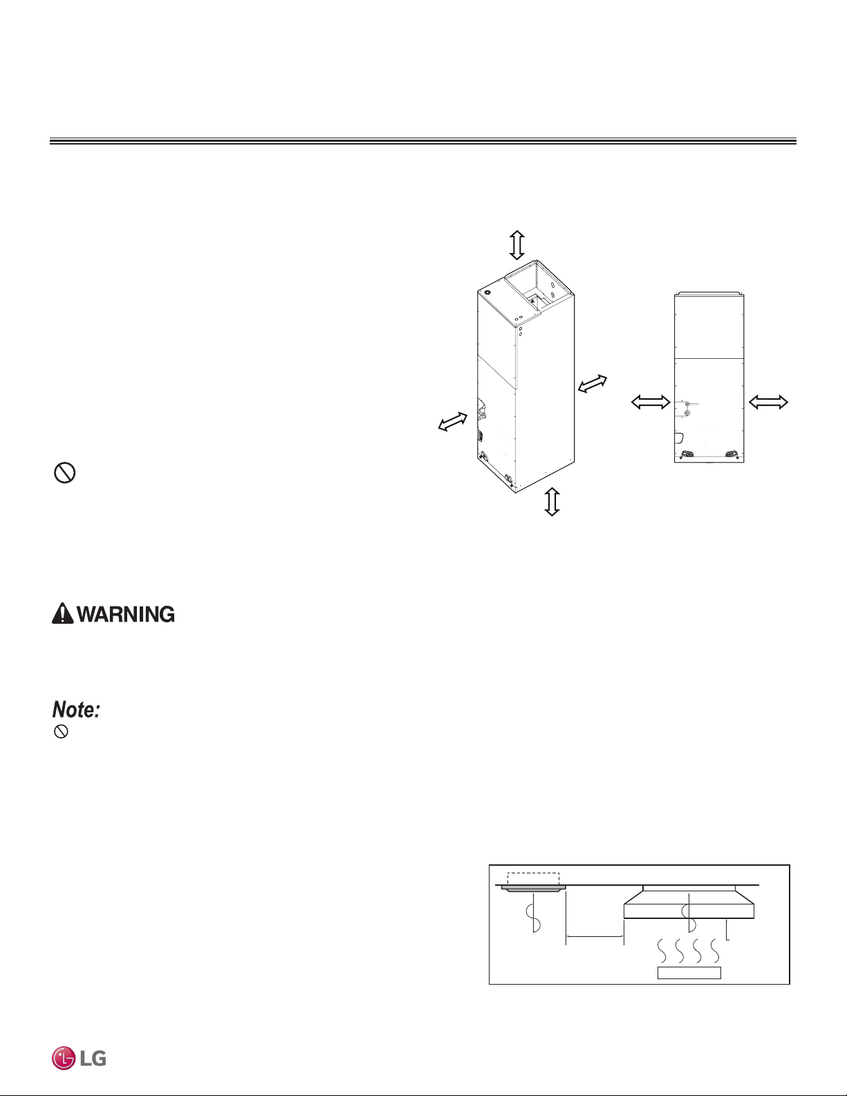
Dos
• Place the unit where air circulation will not be blocked.
• Place the unit where drainage can be obtained easily and to
minimize the length of the condensate drain piping.
• Place the unit where noise prevention is taken into consider-
ation.
• Place the unit in a location that can support the indoor unit
weight, and where the indoor unit can be level.
• The mounting floor must be strong and solid enough to prevent
the indoor unit from vibrating.
• Ensure there is sufficient maintenance and clearance space
(wall, ceiling, or other obstacles; see diagram for clearances).
• Locate the indoor unit in a location where it can be easily con-
nected to the outdoor unit.
If the unit is installed near a body of water, the installation parts are at risk of corroding. Appropriate anti-corrosion methods must be taken for the unit
and all installation parts.
Don’ts
• Avoid installing the unit near high-frequency generators.
• No obstacles must be present to prevent indoor unit air circulation.
• Do not install the unit near a doorway.
• Do not install the unit near a heat or steam source, or where considerable amounts of oil, iron powder, or flour are used. (These materials
may generate condensate, cause a reduction in heat exchanger efficiency, or the drain pump to malfunction. If this is a potential problem,
install a ventilation fan large enough to vent out these materials.)
The unit must not be installed where sulfuric acid and ammable or corrosive gases are generated, vented into, or stored. There is risk of re,
explosion, and physical injury or death.
The unit may be damaged, may malfunction, and / or will not operate as designed if installed in any of the conditions listed.
Figure 41: Recommended Clearances for Vertical Air Handling Unit IDU.
Indoor Unit
Selecting the Best Location for the
Indoor Unit
Installing in an Area Exposed to Unconditioned Air
In some installation applications, areas (floors, walls) in some rooms may be
exposed to unconditioned air (room may be above or next to an unheated garage
or storeroom). To countermeasure:
• Verify that carpet is or will be installed (carpet may increase the temperature by
three [3] degrees).
• Add insulation between the floor joists.
• Install radiant heat or another type of heating system to the floor.
PLACEMENT CONSIDERATIONS
Install a ventilation fan
with sufficient capacity
Heat or steam source
Indoor Unit
Include enough
distance
More than
23-5/8 inches
0 inches*
Minimum 14 inches
0 inches*
*When using top panel access holes
for power wiring / communications cable
Rear
0 inches
Front
Minimum 14 inches
Indoor units (IDUs) must not be placed in an environment where the IDUs may be exposed to harmful volatile organic compounds (VOCs) or in
environments where there is improper air make up or supply or inadequate ventilation. If there are concerns about VOCs in the environment where
the IDUs are installed, proper air make up or supply and/ or adequate ventilation must be provided. Additionally, in buildings where IDUs will be
exposed to VOCs, consider a factory-applied epoxy coating to the fan coils for each IDU.
Figure 42: Installing Near a Heat or Steam Source.
Due to our policy of continuous product innovation, some specications may change without notication.
©LG Electronics U.S.A., Inc., Englewood Cliffs, NJ. All rights reserved. “LG” is a registered trademark of LG Corp.
APPLICATION | 71
Application Guidelines
PLACEMENT CONSIDERATIONS
Outdoor Unit
Selecting the Best Location for the Outdoor Unit
Do not install the unit in an area where combustible gas may generate, ow, stagnate, or leak. These conditions can cause a re, resulting in
bodily injury or death.
• Do not install the unit in a location where acidic solution and spray (sulfur) are often used as it can cause bodily injury or death.
• Do not use the unit in environments where oil, steam, or sulfuric gas are present as it can cause bodily injury or death.
When deciding on a location to place the outdoor unit, be sure to choose an area where run-off from defrost will not accumulate and freeze on
sidewalks or driveways, which may create unsafe conditions. Properly install and insulate any drain hoses to prevent the hose from freezing,
cracking, leaking, and causing unsafe conditions from frozen condensate.
Install a fence to prevent vermin from crawling into the unit or unauthorized individuals from accessing it. Follow the placement guidelines set forth in
“Clearance Requirements”.
Select a location for installing the outdoor unit that will meet the following conditions:
• Where there is enough strength to bear the weight of the outdoor unit.
• A location that allows for optimum air flow and is easily accessible for inspection, maintenance, and service.
• Where piping between the outdoor unit and indoor unit(s) are within allowable limits.
• Include space for drainage to ensure condensate flows properly out of the unit when it is in heating mode. Avoid placing the outdoor unit in
a low-lying area where water could accumulate.
• If the outdoor unit is installed in a highly humid environment (near an ocean, lake, etc.), ensure that the site is well-ventilated and has a lot
of natural light (Example: Install on a rooftop).
Don’ts
• Where it will be subjected to direct thermal radiation from other heat sources, or an area that would expose the outdoor unit to heat or
steam like discharge from boiler stacks, chimneys, steam relief ports, other air conditioning units, kitchen vents, plumbing vents, and other
sources of extreme temperatures.
• Where high-frequency electrical noise / electromagnetic waves will not affect operation.
• Where operating sound from the unit will disturb inhabitants of surrounding buildings.
• Where the unit will be exposed to direct, strong winds.
• Where the discharge of one outdoor unit will blow into the inlet side of an adjacent unit (when installing multiple outdoor units).
The indoor unit may take longer to provide heat, or heating performance will be reduced in winter if the unit is installed:
1� In a narrow, shady location.
2� Near a location that has a lot of ground moisture.
3� In a highly humid environment.
4� In an area in which condensate does not drain properly.
Due to our policy of continuous product innovation, some specications may change without notication.
©LG Electronics U.S.A., Inc., Englewood Cliffs, NJ. All rights reserved. “LG” is a registered trademark of LG Corp.
72 | APPLICATION
Single Zone Vertical Air Handling Unit Engineering Manual
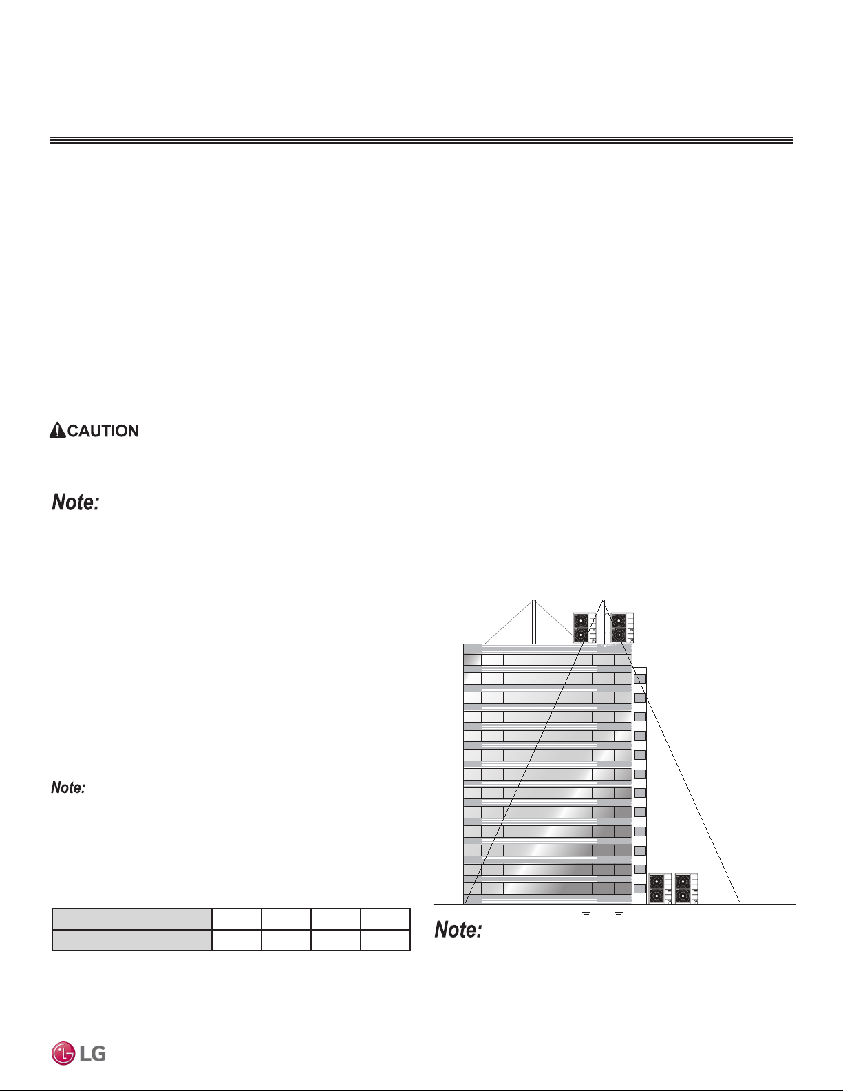
Planning for Snow and Ice
To ensure the outdoor unit operates properly, certain measures are required in locations where there is a possibility of heavy snowfall or
severe windchill or cold:
1. Prepare for severe winter wind chills and heavy snowfall, even in areas of the country where these are unusual phenomena.
2. Position the outdoor unit so that its airflow fans are not buried by direct, heavy snowfall. If snow piles up and blocks the airflow, the
system may malfunction.
3. Remove any snow that has accumulated four (4) inches or more on the top of the outdoor unit.
4. In climates that may experience significant snow buildup, mount the outdoor unit on a raised, field-provided platform or stand. The raised
support platform must be high enough to allow the unit to remain above possible snow drifts, and must be higher than the maximum antici-
pated snowfall for the location.
5. Design the mounting base to prevent snow accumulation on the platform in front or back of the unit frame.
6. Provide a field fabricated snow protection hood to keep snow and ice and/or drifting snow from accumulating on the coil surfaces.
7. Install a hail guard kit and air guide accessories (sold separately) to prevent snow or rain from accumulating on the fan inlet / outlet guards.
8. Consider tie-down requirements in case of high winds or where required by local codes.
When deciding on a location to place the outdoor unit, be sure to choose an area where run-off from defrost will not accumulate and freeze on side-
walks or driveways, which may create unsafe conditions.
Choose an area where run-off from defrost mode will not accumulate and freeze on sidewalks or driveways. Properly install and insulate any drain
hoses to prevent the hose from freezing, cracking, leaking, and damaging the outdoor unit.
Figure 43: Lightning Protection Diagram.
Tie-Downs, Wind Restraints, and
Lightning Protection
Tie-Downs
• The strength of the roof must be checked before installing the
outdoor units.
• If the installation site is prone to high winds or earthquakes, when
installing on the wall or roof, securely anchor the mounting base
using a field-provided tie-down configuration approved by a local
professional engineer.
• The overall tie-down configuration must be approved by a local
professional engineer. Always refer to local code when using a
wind restraint system.
Always refer to local code when designing a wind restraint system.
Lightning Protection
• To protect the outdoor unit from lightning, place the unit within the
specified lightning safety zone.
• Power cable and communication cable must be installed five (5)
feet away from lightning rod.
• A high-resistance ground system must be included to protect
against induced lightning or indirect strike.
Ground
Safe zone
Lightning rod
Protection Angle (25˚~55˚)
1.5m
5 feet
Lightning rod
Table 45: Safety Zone Specications.
Building Height (feet) 66 98 148 197
Protection Angle (˚) 55 45 35 25
If the building does not include lightning protection, the outdoor unit
may be damaged from a lightning strike. Inform the customer of this
possibility in advance.
PLACEMENT CONSIDERATIONS
Outdoor Unit
Due to our policy of continuous product innovation, some specications may change without notication.
©LG Electronics U.S.A., Inc., Englewood Cliffs, NJ. All rights reserved. “LG” is a registered trademark of LG Corp.
APPLICATION | 73
Application Guidelines
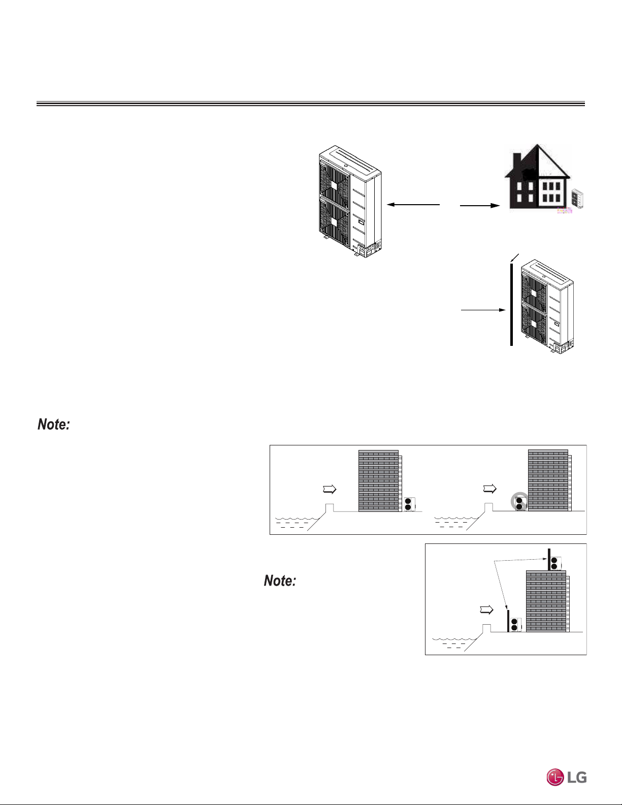
Figure 44: Prevailing Wind
Direction.
Wind Protection
If the outdoor unit is placed on a roof, position it with the compressor
end (no coil surface) in the direction of the prevailing wind as shown
in the figure at right. In cooler climates, it may be beneficial to posi-
tion the unit in direct sunlight to assist with defrost operations.
If the outdoor unit is not placed on a roof, place it on the leeward
side of the building or in a location where the unit will not be ex-
posed to constant wind.
If placement exposes the unit to constant wind activity, construct a
wind break in front of the unit. Follow the placement guidelines set
forth in “Clearance Requirements”.
Prevailing Winds
Prevailing
Winds
Figure 45: Leeward Side of the
Building.
Prevailing Winds
Wall or Other Wind Break
Figure 46: Wind Break.
Mounting Platform
The underlying structure or foundation must be designed to support the weight of the unit. Avoid placing
the unit in a low lying area where water may accumulate.
Oceanside Installation Precautions
• Avoid installing the outdoor unit where it would
be directly exposed to ocean winds.
• Install the outdoor unit on the side of the building
opposite from direct ocean winds.
• Select a location with good drainage.
• Periodically clean dust or salt particles off of the
heat exchanger with water.
Tie-Downs and Wind Restraints
The strength of the Vertical Air Handling Unit frames is adequate to be used with field-provided wind re-
straint tie-downs. The overall tie-down configuration must be approved by a local professional engineer.
Always refer to local code when designing a wind restraint system.
If the outdoor unit must be placed in a location
where it would be subjected to direct ocean winds,
install a concrete windbreaker strong enough to
block any winds. Windbreaker height and width
must be more than 150% of the outdoor unit, and
be installed at least 27-1/2 inches away from the
outdoor unit to allow for airflow.
Ocean winds may cause corrosion, particularly
on the condenser and evaporator ns, which, in
turn could cause product malfunction or inefcient
performance.
PLACEMENT CONSIDERATIONS
Outdoor Unit
Ocean winds
Ocean winds
Ocean winds
Windbreaker
Figure 47: Oceanside Placement Using a Building as Shield, and Placement Using a
Windbreak.
Additional anti-corrosion treatment may
need to be applied to the outdoor unit at
oceanside locations.
Due to our policy of continuous product innovation, some specications may change without notication.
©LG Electronics U.S.A., Inc., Englewood Cliffs, NJ. All rights reserved. “LG” is a registered trademark of LG Corp.
74 | APPLICATION
Single Zone Vertical Air Handling Unit Engineering Manual
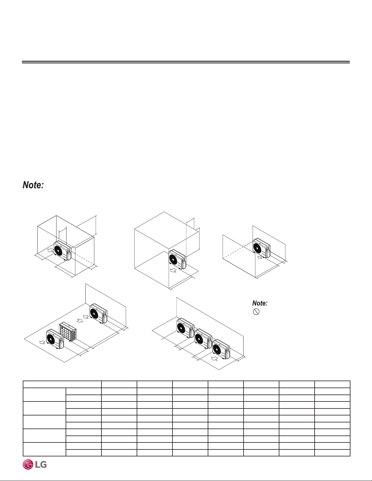
CLEARANCES
Outdoor Unit
Minimum Clearance Requirements for Vertical Air Handling Unit ODUs
Proper clearance for the outdoor unit coil is critical for proper unit operation. When installing the outdoor unit, consider service, inlet and
outlet and minimum allowable space requirements as illustrated in the diagrams below and on the next few pages.
Minimum Clearance Requirements for LUU188HV, LUU248HV Outdoor Units
Specific clearance requirements in the diagram below are for 18,0000 Btu/h (LUU188HV),and 24,000 Btu/h (LUU248HV) systems. The fol-
lowing figure shows the overall minimum clearances that must be observed for safe operation and adequate airflow around the outdoor unit.
When placing the outdoor unit under an overhang, awning, sunroof or other “roof-like structure”, observe the clearance requirements (as
shown in Cases 1 and 2 for height in relation to the unit. This clearance ensures that heat radiation from the condenser is not restricted
around the unit.
Adhere to all clearance requirements if installing the unit on a roof. Be sure to level the unit and ensure that the unit is adequately anchored.
Consult local codes for rooftop mounting requirements.
To have successful service access to the outdoor unit, see the following figure for minimum spacing. When installing multiple outdoor units,
see Cases 4 and 5 for correct spacing requirements.
Figure 48: Outdoor Unit Service Access and Allowable Clearances Diagram.
A
B
D
G
C
G
C
D
E
D
D
B
B
F
1/16 inch
20 inches or less
Case 1
Case 4
Case 2 Case 3
Case 5
20 inches or less
Unit: Inch A B C D E F G
Case 1
Standard 12 24 - 12 - - -
Minimum 4 10 - 4 - - 40
Case 2
Standard - - 20 - - - -
Minimum - - 14 - - - 40
Case 3
Standard - - 20 12 - - -
Minimum - - 14 4 - - -
Case 4
Standard - - - 12 24 - -
Minimum - - - 4 8 79 -
Case 5
Standard - 24 - 12 - - -
Minimum - 10 - 4 - - -
Table 46: 24K Outdoor Unit Service Access and Allowable Clearances Diagram Legend.
Do not place the unit where animals
and/or plants will be in the path of the warm
air, or where the warm air and / or noise will
disturb neighbors.
If the outdoor unit is installed between standard and minimum clearances, capacity decreases approximately 10%.
Due to our policy of continuous product innovation, some specications may change without notication.
©LG Electronics U.S.A., Inc., Englewood Cliffs, NJ. All rights reserved. “LG” is a registered trademark of LG Corp.
APPLICATION | 75
Application Guidelines
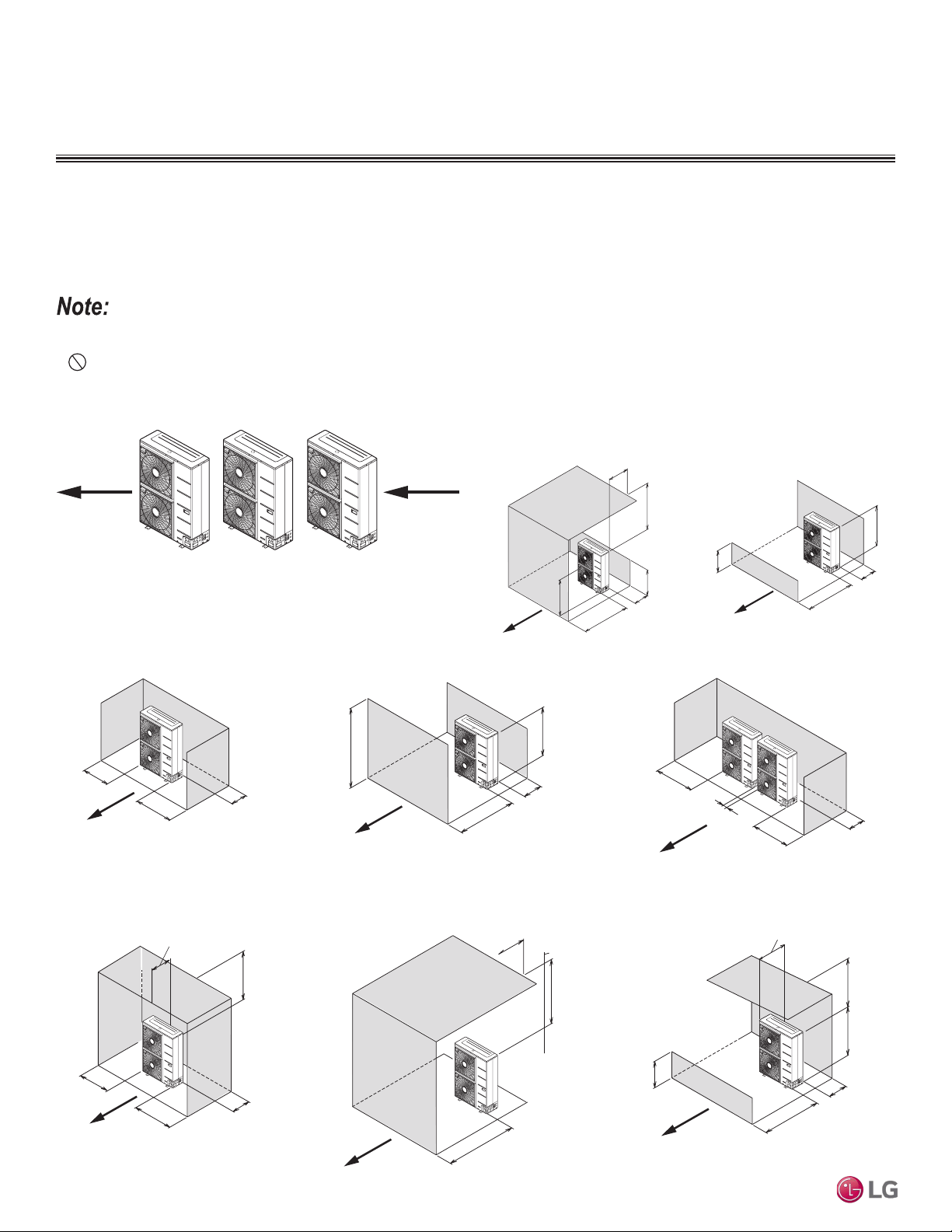
Minimum Clearance Requirements for LUU368HV, LUU428HV, LUU488HV Outdoor Units
Figures below and on the next page illustrate clearance requirements for various installation scenarios for 38,000 Btu/h (LUU368HV), 42,000
Btu/h (LUU428HV), and 48,000 Btu/h (LUU488HV) outdoor units. Use the hot isle / cold isle approach when placing multiple units in close
proximity to each other. Outdoor unit fans draw air from the back of the unit and discharges out the front. Place units back to back and face to
face.
Legend
LR = Rear wall height
LF = Front wall height
H = Unit height
• Installation clearances must comply with local building codes.
• All figures not to scale.
• Never place multiple units facing back to front or front to back as shown immediately below here or
high and low system pressure problems may occur.
Min. 4"
Min. 20"
LF ≤ H
Min. 40"
LR < H
Max. 20"
LR
H
Min. 10"
Min. 40"
Single Unit—High Front Wall with Building Overhang
and No Side Walls
Single Unit—High Rear Wall and Low Front Wall
with No Side Walls
A
i
r
fl
o
w
A
i
r
fl
o
w
LF
H
Min. 4"
Min. 4"
Min. 4"
Min. 4"
Min. 20"
Min. 4"
Min. 4"
Min. 40"
Min. 12"
Min. 6"
Min. 4"
Max. 20"
Min. 40"
Min. 40"
Min. 12"
Min. 40"
Max. 20"
Max. 20"
Min 40"
Min. 20
"
Single Unit—High Rear Wall with or
without High Side Walls
Single Unit—High Rear and Front Walls with
No Side Walls
Side by Side—High Rear and Side Walls
Single Unit—High Rear and Side Walls with
Building Overhang
Single Unit—High Front and Rear Walls with
Building Overhang and No Side Walls
Single Unit—High Rear Wall and Low Front Wall
with Building Overhang and No Side Walls
A
i
r
fl
o
w
A
i
r
fl
o
w
A
i
r
fl
o
w
A
i
r
fl
o
w
A
i
r
fl
o
w
A
i
r
fl
o
w
LF ≥ H
LF
H
Min. 6"
LF ≤ H
LF
H
Airflow
Airflow
Figure 49: Improper Outdoor Unit Placement. Figure 50: Proper Outdoor Unit Placement and Clearances.
Figure 51: Proper Outdoor Unit Placement and Clearances, continued.
CLEARANCES
Outdoor Unit
Due to our policy of continuous product innovation, some specications may change without notication.
©LG Electronics U.S.A., Inc., Englewood Cliffs, NJ. All rights reserved. “LG” is a registered trademark of LG Corp.
76 | APPLICATION
Single Zone Vertical Air Handling Unit Engineering Manual
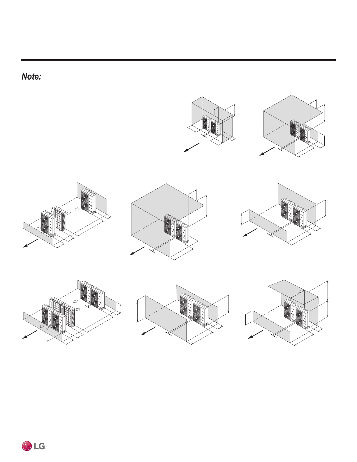
Max. 20"
Min. 40"
Min. 40"
Min. 4"
Min. 4"
Min. 12"
LR < H
Min. 40"
Min. 50
"
Max. 20"
Min. 4"
Min. 12"
Side by Side—High Rear and Side
Walls with Building Overhang
Side by Side—High Rear and Front Walls
with Building Overhang
A
irfl
o
w
A
irfl
o
w
LR
Min. 40"
Min. 8"
Min. 79"
Min. 4"
LF
≤
H
Min. 59"
Min. 12"
Min 4"
Min. 40"
Min. 40"
Max. 20"
Min. 4"
Min. 12"
Min. 119"
Min. 24"
Min. 59
"
Min. 4"
LR ≤ H
Min. 40
"
Min. 12"
Min 4"
LF
≤
H
Min. 59
"
Min. 12"
Min 4"
Min. 40"
Max. 20"
Single Row Units—High Rear Wall and Low Front Wall with
No Side Walls or Overhang
Side by Side —High Front Wall with Building Overhang
and No Side or Rear Walls
Side by Side—High Rear Wall and Low Front Wall with No Side Walls
Double Row Units—Low Rear and Front Walls with No Side
Walls or Overhang
Side by Side—High Front and Rear Walls with No Side Walls Side by Side—High Rear Wall and Low Front Wall with Building
Overhang and No Side Walls
A
i
r
fl
o
w
A
i
r
fl
o
w
A
i
r
fl
o
w
A
i
r
fl
o
w
A
i
r
fl
o
w
A
i
r
fl
o
w
LF
H
H
LR
LF > H
LF
H
LF
H
Legend
LR = Rear wall height
LF = Front wall height
H = Unit height
• Installation clearances must comply with local building codes.
• All figures not to scale.
Figure 52: Proper Outdoor Unit Placement and Clearances, continued.
Figure 53: Proper Outdoor Unit Placement and Clearances, continued.
CLEARANCES
Outdoor Unit
Due to our policy of continuous product innovation, some specications may change without notication.
©LG Electronics U.S.A., Inc., Englewood Cliffs, NJ. All rights reserved. “LG” is a registered trademark of LG Corp.
APPLICATION | 77
Application Guidelines

Installing Outdoor Units Indoors
LG outdoor units are engineered to be mounted outdoors and include technology designed to minimize the negative effects of winter weath-
er’s freezing rain, sleet, and snow. Some building projects, however, necessitate placing the HVAC outdoor units indoors:
• Lack of ground space.
• Lack of an appropriate outdoor location that meets system design requirements.
• When mounting on the roof is not an option due to a lack of roof space.
• Roof warranty will be voided if mechanical equipment is placed on the membrane.
• On retrofit projects, a former chiller / boiler / air handler equipment room, mechanical area, or penthouse already exists.
• Where a project has vertical, self-contained VAV air handlers on each floor (in lieu of a centralized mechanical room).
• To curtail the potential need for redundant zone heating devices such as wall-fin radiators or duct heaters.
• In extremely cold environments where there is a significant amount of run-time at temperatures well below freezing outside the outdoor unit
ambient air temperature range published in this engineering manual.
Benefits of Installing Outdoor Units Indoors
• Shelters the outdoor unit from direct exposure to prevailing winds that decrease the heating capability of the outdoor unit.
• Protects equipment from freezing precipitation and / or potential ice build-up that could hinder unit operation.
• Maintains coil heat transfer efficiency by reducing the number of and shortening the cycle time for defrost operation.
• Easier maintenance and servicing during inclement weather.
• When mounted in a fully enclosed space, limiting the ambient air temperature may allow the system designer to eliminate oversizing the
outdoor unit to compensate for loss of capacity at low ambient temperatures.
• May also curtail the need to provide inefficient redundant zone heating devices such as wall-fin radiators and second-stage ancillary
heating devices.
Design Considerations Include:
• Enclosure types and elements such as louvers, rain hoods, dampers and controls, heating methods and sizing of heating devices
• Heating strategies
• Duct design
• Condensate handling
General Guidelines
• Follow ASHRAE 62.1 design guidelines.
• Depending on the project / application, a roof over the outdoor units in combination with a wind break may be all that is necessary.
• Consider the potential for snow accumulation near louvers / roof openings. Outside air intakes and discharge ducts/louvers must be engi-
neered to clear anticipated snow accumulation levels by at least one (1) foot.
• In situations where operation is anticipated at temperatures of -13°F and lower, ancillary heat must be provided to heat the outdoor unit
coils to assure continuous compressor operation and heating.
It may be necessary to use an air guide accessory to prevent discharge air from short-cycling back to the coil inlet.
• Another option is to field manufacture ductwork and mount on top of the unit to encompass the outdoor unit fan discharge and connect to
the exterior discharge grille on the building.
• Avoid using a single duct on multi-fan units to prevent short cycling. Provide a dedicated duct for each outdoor unit fan discharge.
• Consider the direction of prevailing winds and opening placement. If possible, locate inlet openings upwind of discharge openings and other
exhaust outlets.
• When inlet and outlet openings are placed on the same wall, minimum distance between the two openings must be approximately three (3)
feet (minimum distance varies significantly with variations in outlet opening face velocity).
• If roof-mounted ventilation openings are used, strategically locate the inlet ventilation opening(s) upwind of the outlet opening(s).
• Discharge and supply ductwork must be designed to avoid weather related long periods of water entrainment and the potential for
microbial growth.
INSTALLING OUTDOOR UNITS INDOORS
Due to our policy of continuous product innovation, some specications may change without notication.
©LG Electronics U.S.A., Inc., Englewood Cliffs, NJ. All rights reserved. “LG” is a registered trademark of LG Corp.
78 | APPLICATION
Single Zone Vertical Air Handling Unit Engineering Manual

Provide a means to drain the condensate generated during heating mode and defrost cycle in addition to rainwater that infiltrates the inlet
louver enclosed area.
• Install a field-provided drain pan under the outdoor units and provide a path to a nearby floor drain.
• If the ambient air temperature is expected to drop below 32°F in the enclosure, heat the bottom surface of the pan, drain line, and floor
drain so that the condensate does not freeze before reaching the drain.
Allow for ventilation intake and exhaust air based on maximum outdoor unit fan capacity.
• Select the size, type and orientation of architectural louvers with adequate "net free area" face velocity to ensure the total external static
pressure from the outdoor unit fan does not exceed design limitations (see specification data tables).
• No obstructions must be placed in front of the louver that could hamper the free flow (throw) of air.
• Roof top openings and / or discharge and supply louvers must be equipped with screens to prevent bird and insect infiltration.
As always, the best solution for each project balances acceptable heating performance (considering local weather conditions), capital costs,
life cycle energy consumption, and limitations set forth by local building codes.
INSTALLING OUTDOOR UNITS INDOORS
Due to our policy of continuous product innovation, some specications may change without notication.
©LG Electronics U.S.A., Inc., Englewood Cliffs, NJ. All rights reserved. “LG” is a registered trademark of LG Corp.
APPLICATION | 79
Application Guidelines
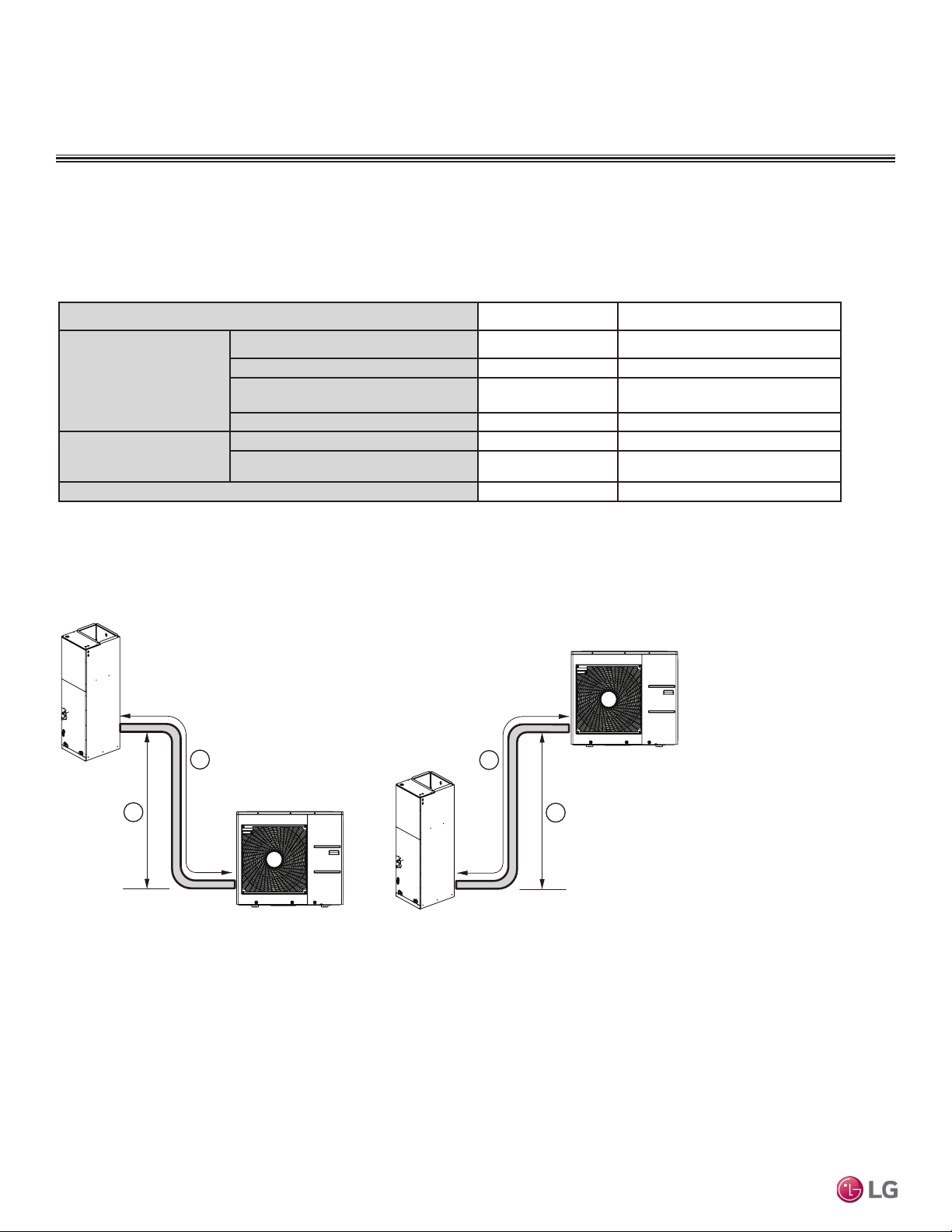
Device Connection Limitations
A single-zone system consists of one outdoor unit and one indoor unit. One of the most critical elements of a single-zone system is the
refrigerant piping. The table below lists pipe length limits that must be followed in the design of a single-zone Vertical Air Handling Unit
refrigerant pipe system.
Table 47: Single-Zone Vertical Air Handling Unit Refrigerant Piping System Limitations.
System Model Name
LV180HV4, LV240HV4 LV360HV4, LV480HV, LV488HV
Pipe Length
(ELF = Equivalent
Length of Pipe in Feet)
Longest total equivalent piping length
164 feet 246 feet
Shortest total equivalent piping length
6.6 feet 6.6 feet
Distance between fittings and indoor or
outdoor units
≥20 inches ≥20 inches
No additional refrigerant
24.6 feet 24.6 feet
Elevation
(All Elevation Limitations are
Measured in Actual Feet)
If outdoor unit is above indoor unit
98 feet 98 feet
If outdoor unit is below indoor unit
98 feet 98 feet
Additional Refrigerant Needed (oz/ft)
0.43 0.43
System Layout
Figure 54: Typical LV180HV4 and LV240HV4 System Layout.
REFRIGERANT PIPING DESIGN
Design Guideline Summary
Outdoor Unit
Indoor Unit
A
B
Outdoor Unit
Indoor Unit
A
B
Unit = Feet
Max. Length = A
Max. Elevation = B
164 164
98 98
Due to our policy of continuous product innovation, some specications may change without notication.
©LG Electronics U.S.A., Inc., Englewood Cliffs, NJ. All rights reserved. “LG” is a registered trademark of LG Corp.
80 | APPLICATION
Single Zone Vertical Air Handling Unit Engineering Manual
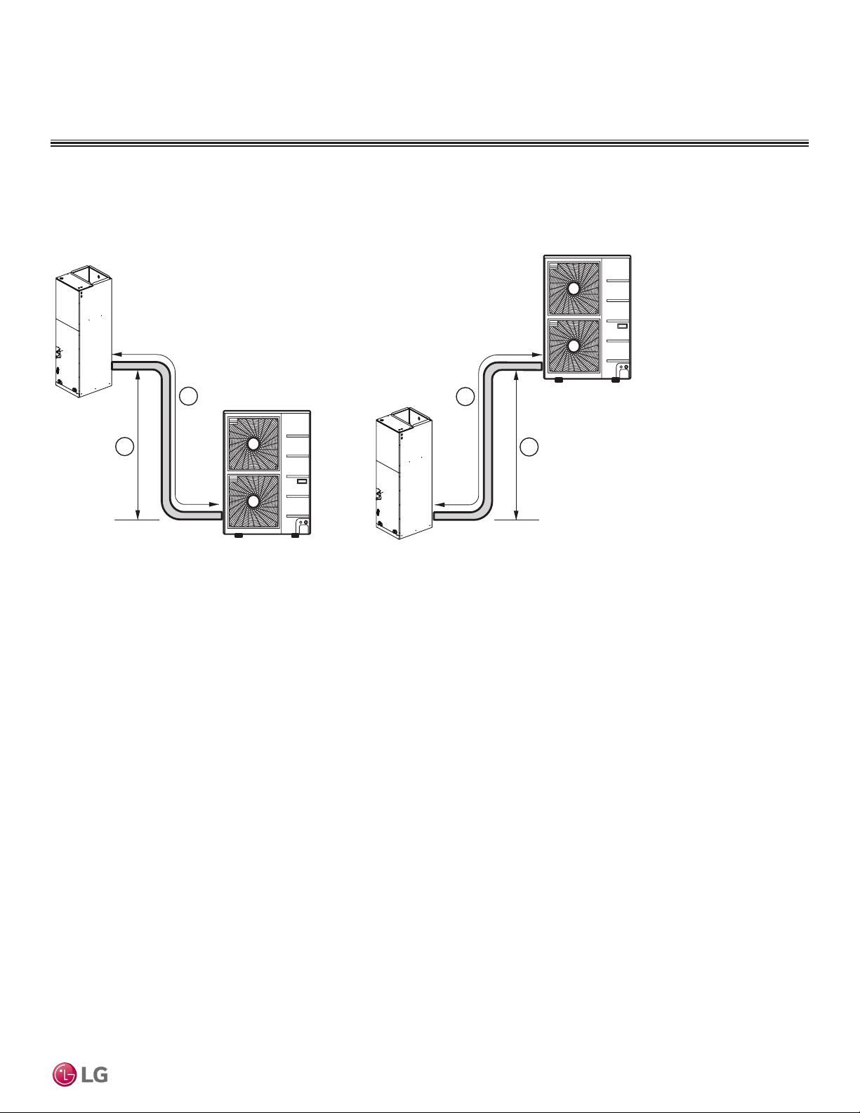
Figure 55: Typical LV360HV4, LV480HV and LV488HV System Layout.
Outdoor Unit
Indoor Unit
A
B
Outdoor Unit
Indoor Unit
A
B
Unit = Feet
Max. Length = A
Max. Elevation = B
246
246
98 98
REFRIGERANT PIPING DESIGN
Design Guideline Summary
System Layout
Due to our policy of continuous product innovation, some specications may change without notication.
©LG Electronics U.S.A., Inc., Englewood Cliffs, NJ. All rights reserved. “LG” is a registered trademark of LG Corp.
APPLICATION | 81
Application Guidelines
EM_SZ_Vertical_Air_Handling_Unit_02_18
Supersedes: EM_SZ_Vertical_Air_Handling_Unit_12_17
EM_SZ_Vertical_Air_Handling_Unit_09_17
20001747 ISO 9001: 2008
LG ELECTRONICS INC.
LG Electronics Commercial Products Support
1-888-865-3026 USA
Follow the prompts for commercial A/C products.
LG Electronics, U.S.A., Inc.
Air Conditioning Technologies
4300 North Point Parkway
Alpharetta, Georgia 30022
www.lghvac.com