O m m 'w//////al&_Aiiiiiiiiiiiiir
/m
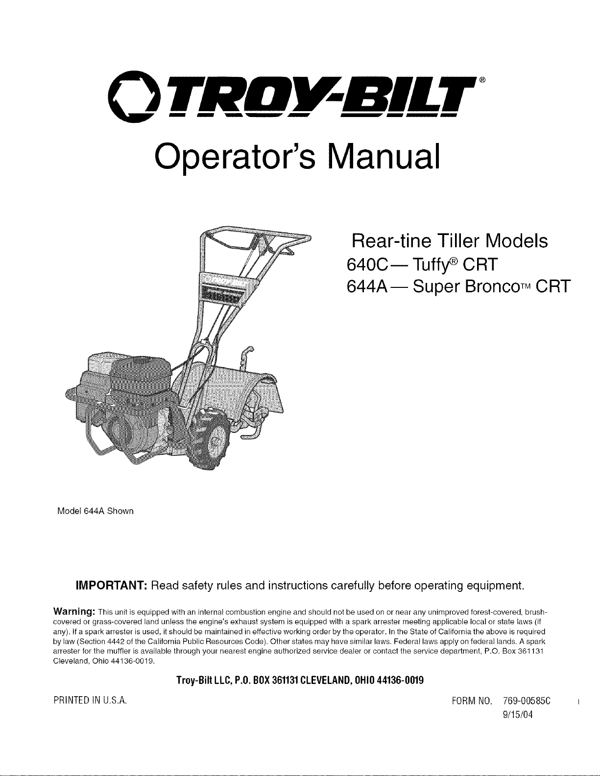
Operator's Manual
®
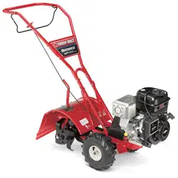
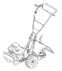
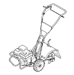
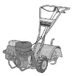
Rear-tine Tiller Models
640C-- Tuffy_ CRT
644A m Super Bronco TM CRT
Mode1644A Shown
IMPORTANT: Read safety rules and instructions carefully before operating equipment.
Warning: This unit is equipped with an internal combustion engine and should not be used on or near any unimproved forest-covered, brush-
covered or grass-covered land unless the engine's exhaust system is equipped with a spark attester meeting applicable local or state laws (if
any). If a spark arrester is used, it should be maintained in effective working order by the operator. In the State of California the above is required
by law (Section 4442 of the California Public Resources Code). Other states may have similar laws. Federal laws apply on federal lands. A spark
arrester for the muffler is available through your nearest engine authorized service dealer or contact the service department, P.O. Box 361131
Cleveland, Ohio 44136-0019.
Troy-Bilt LLC,P.O.BOX361131CLEVELAND,OHIO44136-0019
PRINTEDIN U.S.A. FORMNO. 769-00585C
9/15/04
TABLEOFCONTENTS
Content Page Content Page
Customer Support 2 Maintenance 17
Safety 3 Off-season Storage 21
Assembly 6 Troubleshooting 22
Features and Controls 10 Parts List 23
Operation 12 Warranty Back Cover
FINDINGMODELNUMBER
This Operator's Manual is an important part of your new lawn tractor. It will help you assemble, prepare and maintain the
unit for best performance. Please read and understand what it says.
Before you start assembling your new equipment, please locate the model plate on the equipment and
copy the information from it in the space provided below. A sample model plate is also given below. You can
locate the model plate by looking at the rear of the tine shield. This information will be necessary to use the
manufacturer's web site and/or help from the Customer Support Department or an authorized service dealer.
OTRDV-BILT T,OV-BmLTLLC
P. O. BOX 361131
www.troybilt.com CLEVELAND,OH44136
330-558-7220
,. 1-800-520-552_
Copy the model number here:
Copy the serial number here:
CUSTOMERSUPPORT
PleasedoNOTreh/m thel/nit totheretailer withoutfirstcontactingCustomerSupport.
If you have difficulty assembling this product or have any questions regarding the controls, operation or maintenance of
this unit, you can seek help from the experts. Choose from the options below:
Visit troy-bilt.com for many useful suggestions. Click on Customer Support button and you
will get the four options reproduced here. Click on the appropriate button and help is
immediately available.
/;/ ,> ;'V }/ )
..... f ; @; t ;D
j;_ ?" #'s " 4t, ' F_ i/!s ,
* ;,, #FOX }_ j,"
,v yO, ,_;7f'_;:'
_ 7>,,,,
,,, >,, rL;," ¢j ,_ <# ft, *x J ,7;; _
'_,-., _tf';_'ivc ,l
If you prefer to reach a Customer Support Representative, please call 1(800) 520-5520.
The engine manufacturer is responsible for all engine-related issues with regard to
performance, power-rating, specifications, warranty and service. Please refer to the engine
manufacturer's Owner's/Operator's Manual, packed separately with your unit, for more
information.
SECTION1: SAFETY
This machine meets voluntary safety stan-
dard B71.8-1996, which is sponsoredbythe
Outdoor Power Equipment Institute, Inc.,
and is published by the American National
Standards Institute.
WARNING
The engine exhaust from this productcontains
chemicals known to the State of California to
cause cancer, birth defects or other reproduc-
SafetyAlertSymbol
,_ This is a safety alert symbol. It is used
in this manual and on the unit to alert
you to potential hazards. When you see
this symbol, read and obey the
message that follows it. Failure to obey
safety messages could result in
personal injury or property damage.
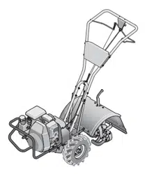
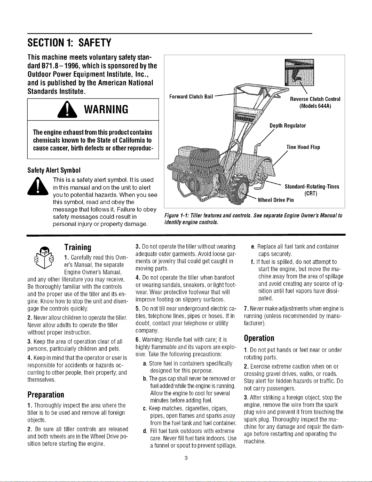
ForwardClutchBail
ReverseClutchControl
(Models644A)
DepthRegulator
TineHoodFlap
Standard-Rotating-Tines
(CRT)
DrivePin
Figure 1-1:Tiller featuresand contre/s. See separateEngineOwner'sManua/ to
identifyenginecontre/s.
Training
1. Carefully readthis Own-
er's Manual,the separate
Engine Owner'sManual,
and anyother literature you may receive.
Bethoroughly familiar with the controls
andthe proper useofthe tiller and its en-
gine. Knowhowto stop the unit and disen-
gagethe controls quickly.
2. Neverallowchildrento operatethetiller.
Neverallow adults to operatethe tiller
without proper instruction.
3. Keepthe area of operationclear of all
persons, particularly children and pets.
4. Keepin mindthat theoperatoror useris
responsible for accidents or hazardsoc-
curring to otherpeople,their property,and
themselves.
Preparation
1. Thoroughly inspect the areawherethe
tiller is to be usedand removeall foreign
objects.
2. Be sure all tiller controls are released
and bothwheels arein theWheelDrive po-
sition beforestarting the engine.
3. Donot operatethetiller without wearing
adequateoutergarments. Avoid loosegar-
ments or jewelry that could get caught in
moving parts.
4. Donot operatethe tiller when barefoot
or wearingsandals,sneakers,or light foot-
wear.Wear protective footwear that will
improve footing on slippery surfaces.
5. Donottill nearunderground electricca-
bles,telephone lines, pipes or hoses.If in
doubt, contact your telephoneor utility
company.
6. Warning: Handlefuel with care; it is
highly flammableand its vapors areexplo-
sive.Takethe following precautions:
a. Storefuel in containers specifically
designedfor this purpose.
b. Thegascapshallneverberemovedor
fueladdedwhiletheengineisrunning.
Allowthe engineto coolforseveral
minutesbeforeaddingfuel.
c. Keepmatches,cigarettes, cigars,
pipes, openflamesand sparksaway
from thefueltank and fuelcontainer.
d. Fillfuel tank outdoors with extreme
care.Neverfill fueltank indoors. Use
a funnelor spout to preventspillage.
e. Replaceall fueltank and container
caps securely.
f. Iffuel isspilled, do not attempt to
start the engine,but move the ma-
chineawayfrom the areaof spillage
and avoidcreating any source of ig-
nition until fuel vapors havedissi-
pated.
7. Nevermakeadjustmentswhenengineis
running (unless recommendedby manu-
facturer).
Operation
1. Do not put hands or feet near or under
rotating parts.
2. Exerciseextremecaution when on or
crossing gravel drives,walks, or roads.
Stayalert for hiddenhazardsor traffic. Do
not carry passengers.
3. After striking a foreign object, stop the
engine,removethe wire from the spark
plug wire and prevent it from touching the
spark plug. Thoroughly inspectthe ma-
chine for any damageand repairthe dam-
agebefore restarting and operatingthe
machine.
4.Exercisecautiontoavoidslippingorfall-
ing.
5.Iftheunitshouldstarttovibrateabnor-
mally,stoptheengine,disconnectthe
sparkplugwireandpreventitfromtouch-
ingthesparkplug,andcheckimmediately
forthecause.Vibrationisgenerallya
warningoftrouble.
6. Stopthe engine, disconnectthe spark
plug wire and prevent it from touching the
spark plug,wheneveryou leavethe operat-
ing position, beforeunclogging thetines,
or whenmaking any repairs, adjustments
or inspections.
7. Takeall possible precautionswhenleav-
ing the machine unattended.Stopthe en-
gine. Disconnectthespark plug wire and
move it awayfrom thespark plug. Besure
that both wheelsarein theWheelDrive po-
sition.
8. Beforecleaning, repairing,or inspect-
ing, stop the engine and make certain all
moving parts havestopped. Disconnect
the spark plug wire and prevent it from
touching thespark plugto preventacci-
dentalstarting.
9. Theflapon thefine hood must bedown
when operatingthetiller.
10. Neverusethetiller unless proper
guards, plates,or other safety protective
devicesare in place.
11. Donot run the engine in an enclosed
area.Engineexhaust containscarbon
monoxide gas, a deadlypoison that is
odorless, colorless, and tasteless.
12. Keepchildren and pets away.
13. Never operate thetiller underengine
powerif thewheels arein theFreewheel
position.Inthe Freewheelposition, the
wheelswill not hold the tiller back andthe
revolvingtines could propel thetiller rapid-
ly,possibly causingloss ofcontrol. Always
engagethe wheels with the wheel drive
pins in theWheel Drive position before
starting the engine or engaging the
tines4Nheelswith the Forward Clutch Bail
(all models)or the ReverseClutchcontrol
(Model 644A only).
14. Beawarethatthe tiller may unex-
pectedlybounceupwardor jumpforward
if thetines shouldstrike extremelyhard
packedsoil, frozen ground,or buriedob-
stacleslike largestones,roots,or
stumps.
If indoubtaboutthetilling conditions, al-
ways usethefollowing operating precau-
tionstoassistyouin maintainingcontrol
of thetiller:
a. Walk behindandto one side of the
tiller, usingone handon thehandle
barsRelax yourarm, but usea
securehandgrip.
b. Useshallowerdepthregulator
settings,working graduallydeeper
with eachpass.
¢. Useslowerenginespeeds.
d. Clearthetilling area of all large
stones,rootsor other debris.
e. Avoidusingdownwardpressureon
thehandlebars.If needbe, use
slight upwardpressuretokeepthe
tinesfrom diggingtoodeeply.
f. Beforecontacting hardpackedsoil
at the endofa row,reduceengine
speedand lift thehandlebarsto
raise thetines out of the soil.
g. In anemergency,stopthetinesand
wheels byreleasingwhichever
clutch controlis engaged.Do not
attemptto restrainthetiller.
15. Donot overloadthe tiller's capacityby
attempting to till too deeplyat too fast a
rate.
16. Neveroperatethetiller at high trans-
port speeds on hard or slippery surfaces.
Look behind and usecarewhen backing
up.
17. Donot operatethetiller on aslopethat
is too steep for safety.When on slopes,
slow down and makesure you havegood
footing. Neverpermit thetillerto freewheel
down slopes.
18. Neverallow bystanders nearthe unit.
19. Onlyuseattachmentsand accessories
that are approved bythe manufacturer of
the tiller.
20. Usetiller attachmentsand accessories
when recommended.
21. Neveroperatethetiller without good
visibility orlight.
22. Neveroperatethe tiller ifyou aretired;
or underthe influence ofalcohol, drugs or
medication.
23. Operatorsshallnottamper with theen-
gine-governor settings onthe machine;
the governor controls the maximum safe
operatingspeedto protectthe engine and
all moving parts from damagecaused by
overspeed.Authorized serviceshall be
sought if a problem exists.
24. Do nottouch engine parts which may
behot from operation.Letparts cool down
sufficiently.
25. Pleaseremember:Youcanalwaysstop
thetines and wheels by releasingthe For-
ward ClutchBail or on Model644Athe Re-
verseClutchcontrol, (whichevercontrol is
engaged),or bymoving the ignition switch
and/orthrottle control leveron the engine
to "OFF"or "STOP".
26. Toload or unloadthe tiller, seethe in-
structions in Section4 of this Manual.
27. Useextremecaution when reversing
or pulling the machinetowards you.
28. Startthe enginecarefully accordingto
instructions and with feetwell awayfrom
thetines.
29. Neverpick up or carry a machinewhile
the engineis running.
MaintenanceandStorage
1. Keepthe tiller, attachmentsand acces-
sories in safeworking condition.
2. Checkall nuts, bolts, and screws for
proper tightness to besurethe equipment
is in safeworking condition.
3. Neverstore thetiller with fuel in thefuel
tank insidea building whereignition sourc-
esare presentsuchashot waterandspace
heaters,furnaces, clothes dryers, stoves,
electric motors, etc.). Allow the engineto
cool beforestoring the unit in anyenclo-
sure.
4. Toreducethe chancesof a fire hazard,
keeptheenginefreeofgrass, leaves,or ex-
cessivegrease.
5. Storegasolinein acool, well-ventilated
area,safelyawayfrom anyspark- or
flame-producing equipment. Store gaso-
line in an approvedcontainer,safelyaway
from the reachof children.
6. Referto the Maintenancesections of
this Manualand the separateEngineOwn-
er'sManualfor instructions ifthe unitis to
bestored for an extendedperiod.
7. Neverperform maintenancewhilethe
engineis running orthe spark plug wire is
connected,exceptwhen specifically in-
structed to do so.
8. Ifthe fueltank hasto be drained,dothis
outdoors.
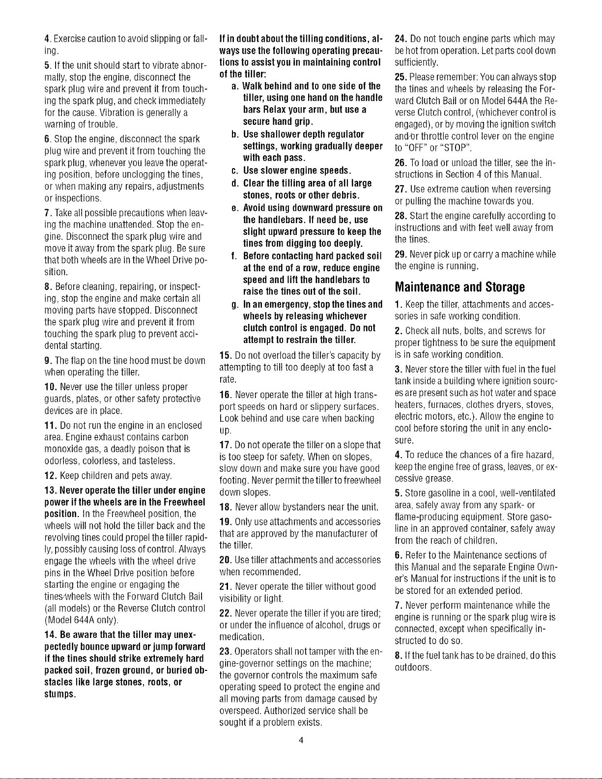
Decals
Foryour safety and the safety of others, vari-
ous safety and operationaldecalsare located
on your unit (seeFigure 1-2).
Keepthe decalscleanand legibleatall times.
Contactyour localservicedealeror thefactory
for replacementsif anydecalsaredamagedor
missing.
Referto the Parts List pagesin this Manualfor
decallocations, descriptions and part num-
bers.
ForwardClutchBail
StartingStabilization
Message(on engine)
ReverseClutch Control
OperatingInstruction
(Models 644A)
WarningMessages
HotSurfacesWarning
Figure 1-2:Locationof safety and operatingdeca/s.
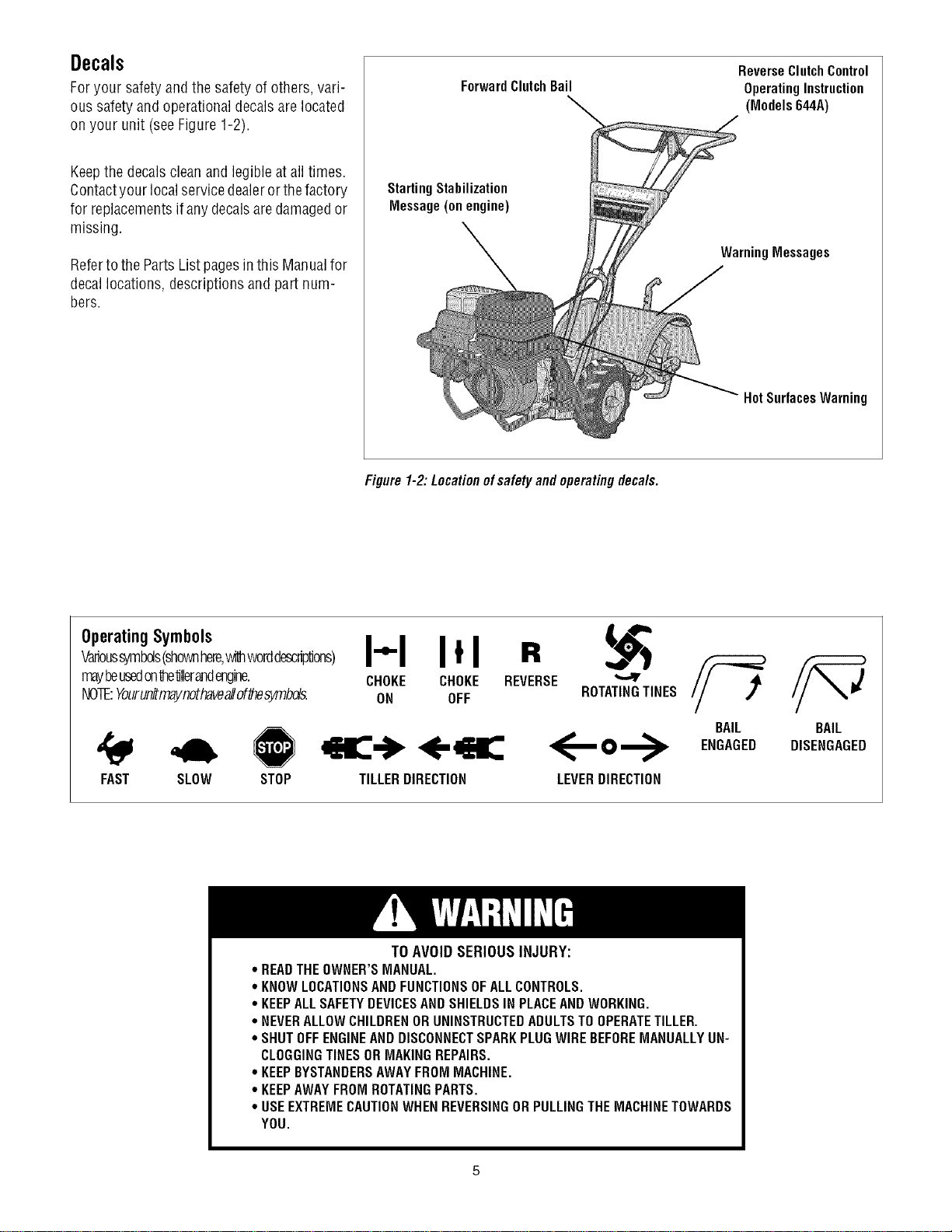
OperatingSymbols
Varioussymbols(shownhere,withworddescriptions)
mayheusedonte'dllerandengine.
NOTE:Yourunitmaynothaveallof_esymbds.
FAST SLOW STOP
I"1 I*1 R
CHOKE CHOKE REVERSE
ON OFF ROTATINGTINES
<,-K,
TILLERDIRECTION
<--o-->
LEVERDIRECTION
BAIL
ENGAGED
BAIL
DISENGAGED
TO AVOID SERIOUS INJURY:
* READTHEOWNER'SMANUAL.
* KNOWLOCATIONSANDFUNCTIONSOFALLCONTROLS.
* KEEPALLSAFETYDEVICESANDSHIELDSIN PLACEANDWORKING.
° NEVERALLOWCHILDRENORUNINSTRUCTEDADULTSTO OPERATETILLER.
° SHUTOFFENGINEAND DISCONNECTSPARKPLUGWIREBEFOREMANUALLYUN-
CLOGGINGTINESORMAKINGREPAIRS.
° KEEPBYSTANDERSAWAYFROM MACHINE.
° KEEPAWAYFROMROTATINGPARTS.
° USEEXTREMECAUTIONWHENREVERSINGOR PULLINGTHEMACHINETOWARDS
YOU.
SECTION2: ASSEMBLY
WARNING: Toprevent
personalinjury or property
damage,do notstartthe engine
until all assemblysteps are
completeandyou haveread
and understandthesafety and
operatinginstructions in this
manual.
INTRODUCTION
Carefullyfollow these assemblysteps to
correctly prepareyour tiller for use. It is
recommendedthatyou readthis Sectionin
its entirety beforebeginning assembly.
NOTE: Various rifler models are
presented in this Manual. Use only the
information appropriate for your tiller
model. Engine styles vary by model, Your
engine may appear differently than those
illustrated in this manual.
INSPECTUNIT
Inspect the unitand carton for damageim-
mediatelyafter delivery.Contactthe carrier
(trucking company) if you find or suspect
damage. Inform them of the damageand
request instructions for filing a claim. To
protect your rights, put your claim in writ-
ing and maila copyto the carrierwithin 15
days after the unit has beendelivered.
ContactTroy-Bilt LLCif you needassis-
tance in this matter.
TOOLS/ MATERIALSNEEDED
(2) 1/2" open-end wrench*
(2) 9/16" open-endwrench*
(1) 3/8" open-endwrench*
(1) Largeadjustable wrench
(Models 644A only)
(1) Scissors (totrim plasticties)
(1) Ruler (for belttension check)
(1) Block of wood (to support tiller when
removing wheels)
(1) Tirepressure gauge (for models with
pneumatictires)
(1) Cleanoil funnel
(1) Motor oil. Refertothe EngineOwner's
Manualfor oil specificationsand
quantityrequired.
* Adjustable wrenchesmay be used.
ASSEMBLYSTEPS
STEP 1: UNPACKING INSTRUCTIONS
NOTE:While unpacking,do not severely
bend anycontrol cables.
1.Thetiller weighs approximately 133 Ibs.
Do notattempt to remove it from the ship-
ping platform until instructed to do so in
these Assembly steps.
2. Removeany packagingmaterial from
the carton. Removeany staplesfrom the
bottom of the carton and removethe car-
ton from the shipping platform.
3. Removeall unassembledparts andthe
separatehardwarebag from the carton.
Checkthat you havethe items listed in the
LooseParts List (contactyour localdealer
or the factory itemsare missing or dam-
aged).
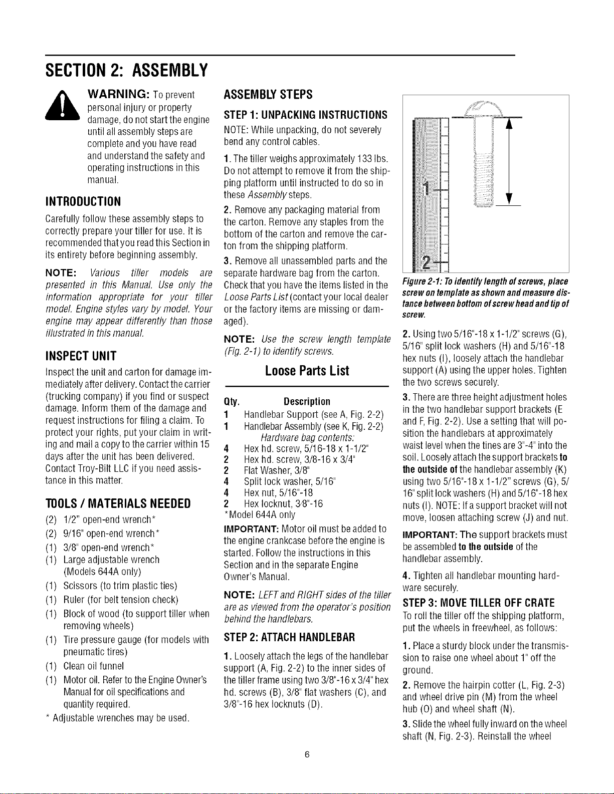
NOTE: Use the screw length template
(Fig,2-1) to identify screws,
LoosePartsList
Qty. Description
1 HandlebarSupport (seeA, Fig. 2-2)
1 HandlebarAssembly(seeK,Fig.2-2)
Hardwarebag contents:
4 Hexhd. screw, 5/16-18 x 1-1/2"
2 Hexhd. screw, 3/8-16 x 3/4"
2 FlatWasher,3/8"
4 Split lockwasher,5/16"
4 Hex nut, 5/16"-18
2 HexIocknut, 34}"-16
*Model 644A only
IMPORTANT:Motor oil must beaddedto
the enginecrankcasebeforetheengine is
started. Followthe instructions inthis
Sectionand in the separateEngine
Owner's Manual.
NOTE: LEFTand RIGHTsides of thetiller
are as viewedfrom theoperator's position
behind thehandlebars.
STEP 2: ATTACHHANDLEBAR
1. Looselyattachthe legsof thehandlebar
support (A, Fig. 2-2) to the inner sides of
the tiller frame usingtwo 3/8"-16x3/4" hex
hd. screws (B), 3/8" flat washers(C), and
3/8"-16 hex Iocknuts (D).
_iiii
Figure2-1: Toidentifylengthofscrews,place
screwontemplateasshownandmeasuredis-
tancebetweenbottomofscrewheadandtipof
screw.
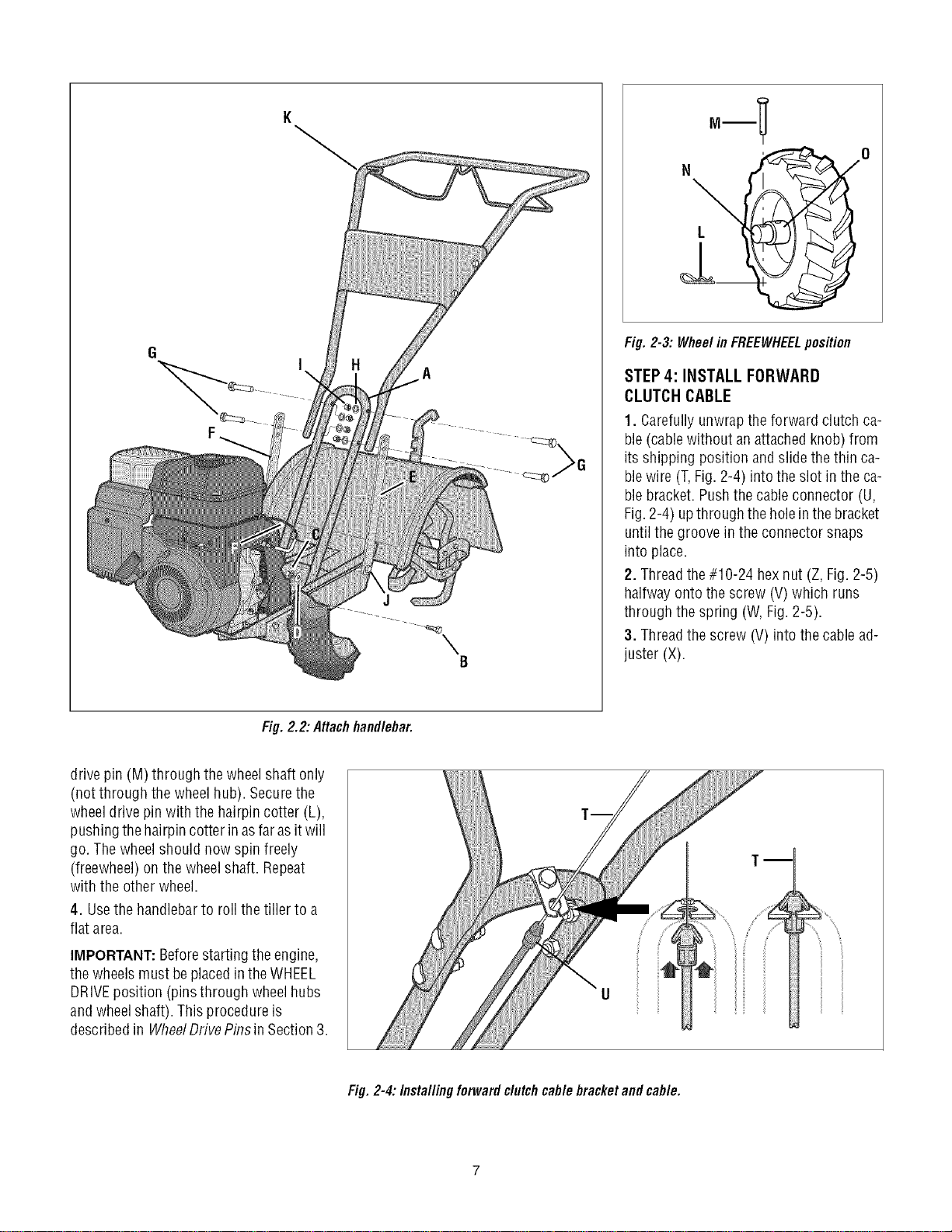
2. Usingtwo 5/16"-18 x 1-1/2"screws (G),
5/16" split lock washers (H) and 5/16"-18
hexnuts (I), looselyattachthe handlebar
support (A) usingthe upperholes.Tighten
thetwo screws securely.
3. Therearethree heightadjustmentholes
in the two handlebar support brackets (E
and F,Fig. 2-2). Usea setting that will po-
sition the handlebarsat approximately
waist levelwhenthetines are3"-4"intothe
soil. Looselyattachthesupport bracketsto
theoutsideofthe handlebarassembly (K)
usingtwo 5/16"-18x 1-1/2" screws (G),5/
16"split lockwashers(H)and5/16"-18 hex
nuts (I). NOTE:Ifa support bracketwill not
move, loosenattaching screw (J) and nut.
IMPORTANT:The support bracketsmust
beassembledtotheoutsideofthe
handlebarassembly.
4. Tightenall handlebarmounting hard-
waresecurely.
STEP 3: MOVE TILLER OFF CRATE
Toroll the tiller off the shipping platform,
put the wheels in freewheel,asfollows:
1. Placeasturdy block underthetransmis-
sion to raiseone wheelabout 1" off the
ground.
2, Removethe hairpin cotter (L, Fig.2-3)
and wheeldrive pin (M) from the wheel
hub (0) and wheelshaft (N).
3. Slidethe wheelfully inwardonthewheel
shaft (N, Fig.2-3). Reinstallthe wheel
A
J
B
°-! °
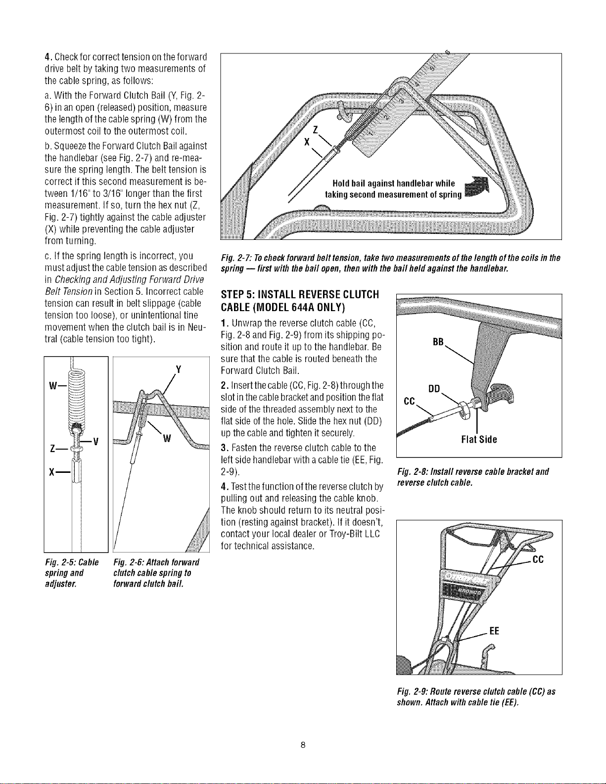
Fig. 2-3: Wheel in FREEWHEELposition
STEP 4: INSTALL FORWARD
CLUTCH CABLE
1. Carefullyunwrapthe forward clutch ca-
ble(cablewithout an attachedknob) from
its shipping position and slide thethin ca-
blewire (T,Fig. 2-4) into the slot in the ca-
blebracket. Pushthe cableconnector (U,
Fig.2-4) upthrough the holein thebracket
untilthe groove in the connector snaps
into place.
2. Threadthe#10-24 hexnut (Z, Fig. 2-5)
halfway ontothe screw (V) which runs
through the spring (W, Fig.2-5).
3. Threadthe screw (V) into the cablead-
juster (X).
Fig. 2.2: Attachhandlebar.
drive pin (M) through thewheelshaft only
(not through the wheelhub). Securethe
wheeldrive pin with the hairpin cotter (L),
pushingthe hairpincotter in asfarasit will
go. Thewheelshould now spin freely
(freewheel) on the wheelshaft. Repeat
with the other wheel.
4. Usethe handlebarto roll the tiller to a
flat area.
IMPORTANT: Beforestartingthe engine,
the wheels must beplacedin theWHEEL
DRIVEposition (pinsthrough wheelhubs
andwheelshaft). This procedureis
describedin WheelDrivePinsin Section3.
Fig. 2-4: Installingforward clutchcable bracketand cable.
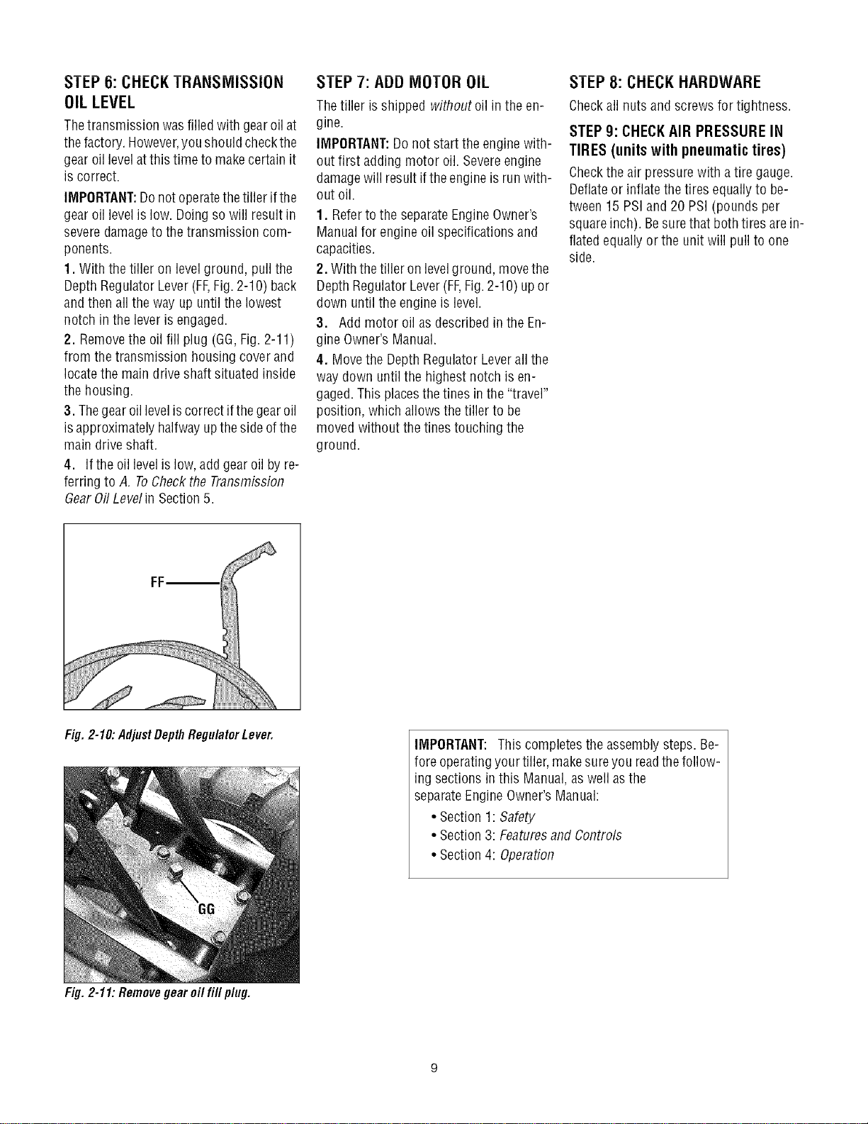
4. Checkfor correcttension ontheforward
drive belt bytaking two measurementsof
the cablespring, as follows:
a.With the Forward Clutch Bail (Y,Fig. 2-
6) in an open (released)position, measure
the length ofthecablespring (W) from the
outermost coil to the outermost coil.
b. Squeezethe ForwardClutch Bailagainst
the handlebar(seeFig. 2-7) and re-mea-
surethe spring length. Thebelt tension is
correct if this second measurementis be-
tween 1/16"to 3/16" longerthanthe first
measurement.If so, turn the hexnut (Z,
Fig. 2-7) tightly against the cableadjuster
(X) while preventingthe cableadjuster
from turning.
c. If the spring lengthis incorrect, you
must adjustthe cabletension asdescribed
in Checkingand Adjusting Forward Drive
Belt Tensionin Section5. Incorrect cable
tension can result in beltslippage (cable
tension too loose), or unintentional tine
movement whenthe clutch bail is in Neu-
tral (cabletension too tight).
Wm
Fig.2-5: Cable
springand
adjuster.
W
Fig. 2-6: Attachforward
clutchcablespringto
forwardclutch bail.
iiiiiiiiiiiiiiii
Fig. 2-7: Tocheckforwardbelt tension,take twomeasurementsof thelengthofthe coils inthe
spring-- first withthebail open, then withthe bail heldagainst thehandlebar.
STEP 5: INSTALL REVERSECLUTCH
CABLE (MODEL 644A ONLY)
1. Unwrapthe reverseclutch cable (CC,
Fig.2-8 and Fig.2-9) from itsshipping po-
sition and route it up to the handlebar.Be
surethat the cableis routedbeneaththe
Forward Clutch Bail.
2. Insertthecable(CC,Fig.2-8)through the
slot inthecablebracketandpositiontheflat
sideof thethreadedassemblynextto the
flat side ofthe hole.Slidethe hexnut (DD)
up thecableandtighten it securely.
3. Fastenthe reverseclutch cableto the
left sidehandlebarwith acabletie (EE,Fig.
2-9).
4. Testthefunction ofthe reverseclutch by
pulling out and releasingthe cableknob.
Theknob should return to its neutral posi-
tion (resting against bracket). If it doesn't,
contact your local dealeror Troy-Bilt LLC
for technical assistance.
Flat Side
Fig. 2-8:/nsta//reverse cablebracketand
reverseclutchcable.
Fig. 2-9: Routereverseclutchcable (CC)as
shown.Attachwithcable tie(EE).
5! 6: CHECKTRAHSMiSSiOH
OILLEVEL
Thetransmission was filledwith gearoil at
thefactory. However,you shouldcheckthe
gear oil levelatthis time to makecertain it
is correct.
IMPORTANT:Donot operatethe tiller ifthe
gear oil level islow. Doingso will result in
severedamageto the transmission com-
ponents.
1. With the tiller on levelground, pull the
Depth RegulatorLever(FF,Fig. 2-10) back
andthen all theway up until the lowest
notch in the lever isengaged.
2. Removethe oil fill plug (GG,Fig.2-11)
from the transmission housing cover and
locatethe maindrive shaft situated inside
the housing.
3. Thegear oil leveliscorrect ifthegear oil
isapproximately halfway upthe sideofthe
main driveshaft.
4. Ifthe oil levelislow, add gear oil by re-
ferring to A. ToCheckthe Transmission
dear 0il Levelin Section5.
I El-'/: AUU IVlUI UH UIL
Thetiller isshipped withoutoil in the en-
gine.
IMPORTANT:Donot start the engine with-
out first adding motor oil. Severeengine
damagewill result ifthe engineis run with-
out oil.
1. Referto the separateEngineOwner's
Manualfor engine oil specifications and
capacities.
2. With thetiller on levelground, movethe
Depth RegulatorLever(FF,Fig.2-10) upor
down until the engine is level.
3. Add motor oil as describedin the En-
gine Owner's Manual.
4. Movethe DepthRegulator Leverall the
way down untilthe highest notch is en-
gaged.This placesthe tines in the"travel"
position, which allows the tiller to be
moved without thetines touching the
ground.
_1 El-'8: I.;HEI.;K HAHUWAHE
Checkall nutsandscrews for tightness.
STEP g: CHECKAIR PRESSURE IN
TIRES (unitswithpneumatictires)
Checkthe air pressurewith a tire gauge.
Deflateor inflatethe tires equallyto be-
tween 15 PSIand 20 PSI (pounds per
squareinch). Besurethat bothtires arein-
flated equallyor the unit will pull to one
side.
Fig. 2-10: AdjustDepthRegulatorLever.
Fig. 2-11: Removegear oil fill plug.
IMPORTANT: This completesthe assembly steps. Be-
fore operatingyour tiller, makesureyou readthefollow-
ing sections in this Manual,as well asthe
separateEngineOwner'sManual:
• Section 1: Safety
• Section 3: Featuresand Controls
• Section 4: Operation
SECTION3: FEATURESANDCONTROLS
_ ARNING: Before
operatingyour machine,
carefully readand understand
all safety,controls and
operatinginstructions in this
Manual,the separateEngine
Owner's Manual,andon the
decalson the machine.
Failureto follow these
instructions can result in
serious personalinjury.
INTRODUCTION
This Section describesthe location and
function ofthecontrols on yourtiller. Refer
to the following Section, Operationfor de-
tailed operatinginstructions.
Practice usingthese controls, with the en-
gine shut off, until you understandthe op-
eration ofthe controls and feelconfident
with eachof them.
ForwardClutch
Bail ReverseClutchControl
(Model 644A)
gulator
HandlebarHeight Adjustment
Wheel Drive Pin
(oneachwheel)
ENGINE CONTROLS
Referto the enginemanufacturer's Engine
Owner'sManual(included in the tiller liter-
aturepackage)to identify the controls on
your engine.
IMPORTANT:Thecontrol for stopping the
engine is located onthe engine.
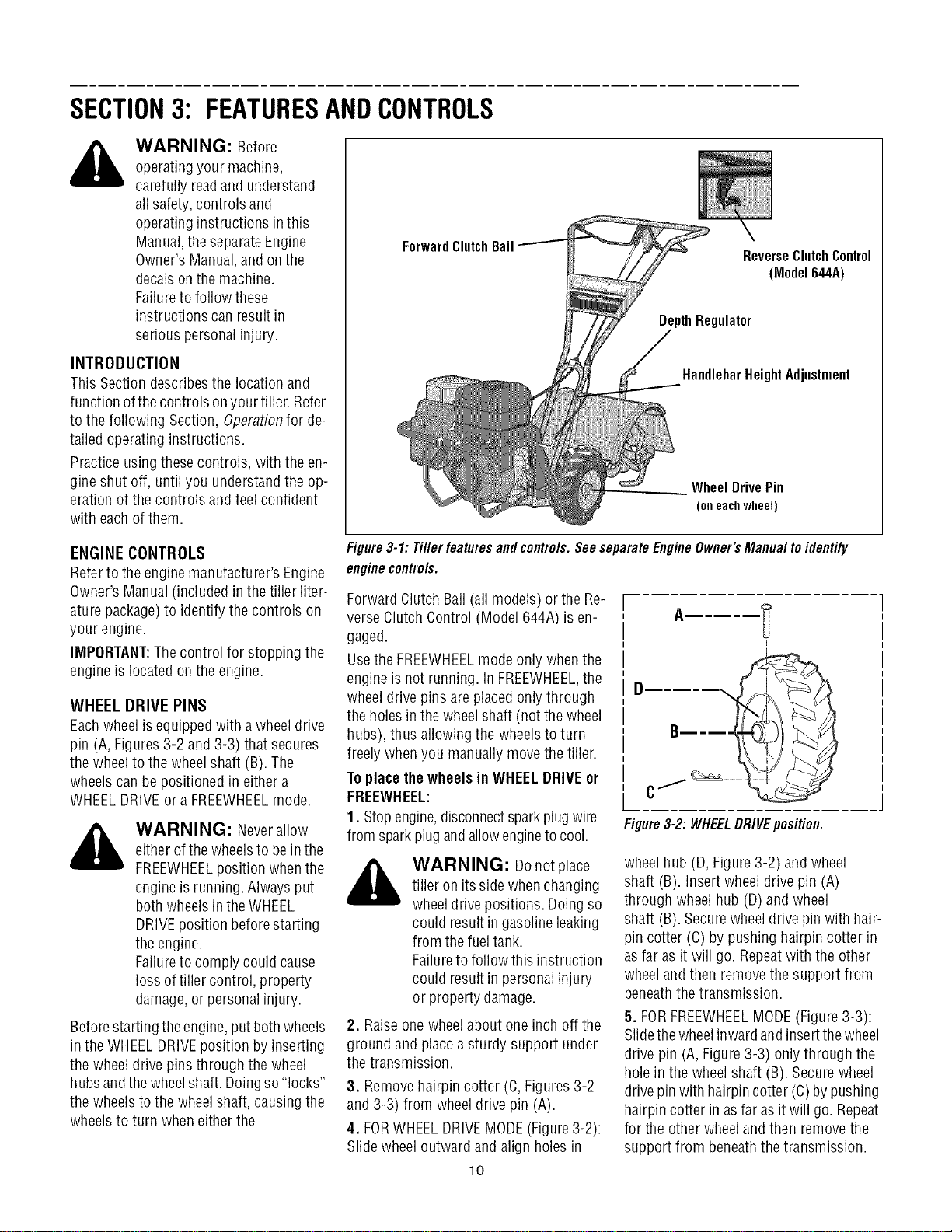
WHEEL DRIVE PINS
Eachwheelis equippedwith a wheeldrive
pin (A, Figures3-2 and 3-3) that secures
the wheelto the wheelshaft (B). The
wheelscan be positioned in either a
WHEELDRIVEor aFREEWHEELmode.
_ WARNING: Neverallow
either ofthewheelsto bein the
FREEWHEELposition whenthe
engineis running. Alwaysput
both wheelsin theWHEEL
DRIVEposition beforestarting
the engine.
Failureto comply could cause
loss of tiller control, property
damage,or personalinjury.
Beforestartingthe engine,put bothwheels
in the WHEELDRIVEposition byinserting
the wheel drive pins through the wheel
hubsandthewheelshaft. Doingso "locks"
the wheels to the wheelshaft, causing the
wheelsto turn when eitherthe
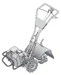
Figure3-1: Tiller features and controls.See separateEngineOwner's Manual to identify
enginecontrols.
Forward ClutchBail (all models) or the Re-
verse ClutchControl (Model 644A) is en-
gaged.
Usethe FREEWHEELmode only whenthe
engineis not running, in FREEWHEEL,the
wheeldrive pins are placedonly through
the holes in thewheelshaft (notthe wheel
hubs), thus allowing the wheels to turn
freely whenyou manually movethe tiller.
Toplacethewheels in WHEELDRIVEor
FREEWHEEL:
1. Stopengine,disconnectsparkplug wire
from sparkplug andallowengineto cool.
_ WARNING: Donotplace
tiller on its sidewhenchanging
wheeldrivepositions. Doingso
could result in gasolineleaking
from the fuel tank.
Failureto follow this instruction
could result in personalinjury
or property damage.
2. Raiseone wheelabout oneinch off the
ground and placeasturdy support under
the transmission.
3. Removehairpin cotter (C,Figures3-2
and 3-3) from wheel drive pin (A).
4. FORWHEELDRIVEMODE(Figure3-2):
Slide wheeloutward and align holes in
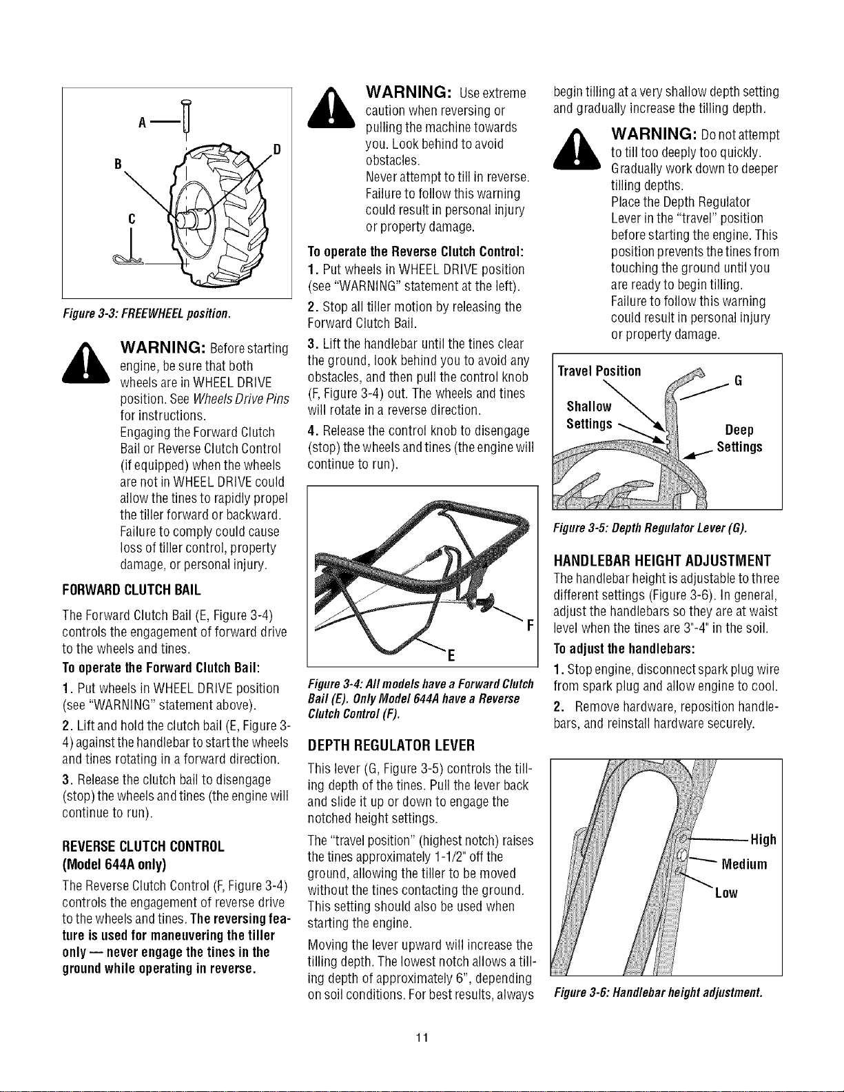
Figure3-2: WHEELDRIVEposition.
wheelhub (D, Figure3-2) and wheel
shaft (B). Insertwheel drive pin (A)
through wheel hub (D)and wheel
shaft (B). Securewheeldrive pin with hair-
pin cotter (C) by pushing hairpin cotter in
asfar as it will go. Repeatwith the other
wheeland then removethe support from
beneaththe transmission.
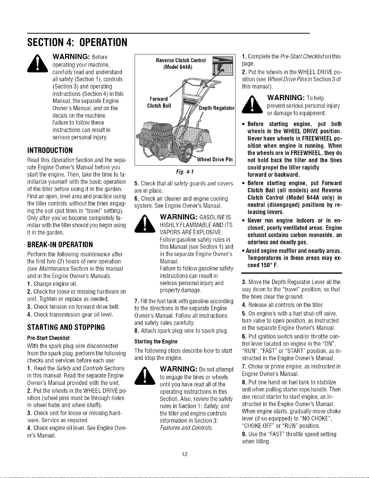
5. FORFREEWHEELMODE(Figure3-3):
Slidethewheelinwardandinsertthewheel
drive pin (A, Figure3-3) onlythrough the
hole in the wheel shaft (B). Securewheel
drivepin with hairpincotter (C)bypushing
hairpin cotter in asfar asit will go. Repeat
for the other wheeland then removethe
support from beneaththetransmission.
lO
_ WARNING: Useextreme
_--'i_ caution whenreversing or
A
Y
pulling the machinetowards
,,_- D you. Look behindto avoid
obstacles.
Neverattemptto till in reverse.
Failureto follow thiswarning
could result in personalinjury
or property damage.
Tooperatethe ReverseClutchControl:
1. Putwheels in WHEELDRIVEposition
(see"WARNING"statementat the left).
2. Stopall tiller motion by releasingthe
Figure3-3:FREEWHEELposition.
Forward Clutch Bail.
WARNING: Beforestarting 3. Lift the handlebar untilthe tines clear
engine,besurethat both the ground, look behind you to avoid any
wheelsare inWHEELDRIVE obstacles,and then pull the control knob
position. SeeWheelsDrivePins (F,Figure3-4) out. Thewheels and tines
for instructions, will rotate in a reversedirection.
Engagingthe Forward Clutch 4. Releasethe control knobto disengage
Bail or ReverseClutchControl (stop)thewheels andtines (theenginewill
(if equipped) whenthewheels continue to run).
arenot in WHEELDRIVEcould
allowthe tinesto rapidly propel
the tiller forward or backward.
Failureto comply could cause
loss of tiller control, property
damage,or personalinjury.
FORWARDCLUTCHBAIL
TheForward Clutch Bail(E, Figure3-4)
controls the engagementof forward drive F
to the wheelsand tines. E
Tooperate the ForwardClutchBail:
1. Put wheelsin WHEELDRIVEposition Figure3-4:AIImodelshavea ForwardClutch
(see"WARNING"statementabove). Bail(E).OnlyMode1644Ahavea Reverse
ClutchControl(F).
2. Lift and hold the clutch bail (E,Figure3-
4)againstthehandlebartostartthewheels DEPTH REGULATOR LEVER
andtines rotatingin a forward direction.
This lever (G,Figure3-5) controls the till-
3. Releasethe clutch bail to disengage ing depthof the tines. Pullthe leverback
(stop) thewheels andtines (theenginewill and slide it up or downto engagethe
continue to run). notched height settings.
REVERSECLUTCHCONTROL The"travelposition" (highestnotch) raises
(Model 644A only) the tines approximately1-1/2"off the
ground, allowingthe tiller to be moved
TheReverseClutchControl (F,Figure3-4) without the tines contactingthe ground.
controls the engagementof reversedrive This setting should also be usedwhen
to the wheelsandtines.The reversing fea- starting the engine.
ture isusedfor maneuveringthe tiller
only-- neverengagethetines in the Moving the leverupward will increasethe
tilling depth.Thelowest notchallowsatill-
ground while operatingin reverse.
ing depthof approximately6", depending
on soil conditions. Forbest results,always
begintilling atavery shallow depthsetting
and gradually increasethe tilling depth.
_b ARNING: Donotattempt
to till too deeplytoo quickly.
Graduallywork downto deeper
tilling depths.
Placethe DepthRegulator
Leverin the "travel" position
beforestarting theengine.This
position preventsthetines from
touching the ground untilyou
are readyto begintilling.
Failureto follow thiswarning
could result in personalinjury
or property damage.
TravelPosition
Figure3-5: DepthRegulator Lever (G).
HANDLEBARHEIGHT ADJUSTMENT
Thehandlebarheight isadjustabletothree
different settings (Figure3-6). In general,
adjust the handlebarssothey areat waist
levelwhenthe tines are3"-4"in the soil.
Toadjustthe handlebars:
1. Stopengine,disconnectspark plugwire
from spark plug and allow engineto cool.
2. Removehardware,reposition handle-
bars,and reinstall hardwaresecurely.
High
Medium
Figure3-6: Handlebarheightadjustment.
11
SECTION4: OPERATION
_ ARNING: Before
operatingyour machine,
carefully readand understand
all safety (Section 1),controls
(Section 3) and operating
instructions (Section4) inthis
Manual,the separateEngine
Owner's Manual,andon the
decalson the machine.
Failureto follow these
instructions can result in
serious personalinjury.
INTRODUCTION
Readthis OperationSection andthe sepa-
rate EngineOwner'sManualbeforeyou
start the engine.Then,take thetime to fa-
miliarize yourself with the basic operation
of thetiller before usingit in the garden.
Findan open,levelareaand practice using
the tiller controls without thetines engag-
ing the soil (put tines in "travel" setting).
Onlyafter you've becomecompletely fa-
miliar with thetiller shouldyou beginusing
it in the garden.
BREAK-INOPERATION
Perform the following maintenanceafter
the first two (2) hours of new operation
(see MaintenanceSection in this manual
and in the Engine Owner'sManual).
1. Changeengine oil.
2. Checkfor looseor missinghardwareon
unit. Tighten or replaceas needed.
3. Checktension on forward drive belt.
4. Checktransmission gear oil level.
STARTING AND STOPPING
Pre-StartChecklist
With the spark plug wire disconnected
from the sparkplug, perform the following
checksand services beforeeachuse:
1. Readthe Safetyand Controls Sections
in this manual.Readthe separateEngine
Owner's Manualprovidedwith the unit.
2. Putthe wheels inthe WHEELDRIVEpo-
sition (wheel pins must be through holes
in wheelhubs and wheelshaft).
3. Checkunit for loose or missing hard-
ware. Serviceas required.
4. Checkengineoil level.SeeEngineOwn-
er's Manual.
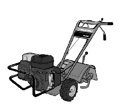
ReverseClutchControl
(Model644A)
ClutchBail
,epthRegulator
/
DrivePin
Fig. 4-1
5. Checkthat allsafetyguards andcovers
are in place.
6. Checkair cleanerand engine cooling
system. SeeEngineOwner's Manual.
,_ WARNING: GASOLINEIS
HIGHLYFLAMMABLEAND ITS
VAPORSAREEXPLOSIVE.
Followgasolinesafety rulesin
this Manual(seeSection 1)and
in theseparateEngineOwner's
Manual.
Failureto follow gasolinesafety
instructions can result in
serious personalinjury and
property damage.
7. Fillthefueltank with gasolineaccording
to the directions inthe separate Engine
Owner's Manual.Follow all instructions
and safety rules carefully.
8. Attachspark plug wire to spark plug.
Startingthe Engine
Thefollowing steps describe how to start
and stop the engine.
,_ WARNING: Donotattempt
to engagethetines or wheels
until you havereadall ofthe
operatinginstructions in this
Section.Also, reviewthe safety
rules in Section 1:Safety,and
the tiller and enginecontrols
information in Section3:
Featuresand Controls.
1. Completethe Pre-StartChecklistonthis
page.
2. Putthe wheels inthe WHEELDRIVEpo-
sition (seeWheelDrivePinsin Section3 of
this manual).
,_ WARNING: Tohelp
preventserious personalinjury
or damageto equipment:
• Before starting engine, put both
wheels in the WHEELDRIVEposition.
Never havewheels in FREEWHEELpo-
sition when engine is running. When
thewheels arein FREEWHEEL,theydo
not hold backthe tiller and the tines
couldpropelthetiller rapidly
forwardor backward.
• Before starting engine, put Forward
Clutch Bail (all models) and Reverse
Clutch Control (Model 644A only) in
neutral (disengaged) positionsby re-
leasinglevers.
• Never run engine indoors or in en-
closed,poorlyventilatedareas. Engine
exhaustcontainscarbonmonoxide,an
odorlessanddeadlygas.
• Avoidenginemufflerandnearbyareas.
Temperaturesin these areas may ex-
ceed 150° F.
3. Movethe Depth RegulatorLeverall the
way down to the "travel" position, sothat
thetines clearthe ground.
4. Releaseall controls on the tiller.
5. Onengine'swith a fuel shut-off valve,
turn valve to openposition, asinstructed
in the separateEngine Owner'sManual.
6. Put ignition switch and/or throttle con-
trol leverlocated on engine in the "ON",
"RUN", "FAST"or "START"position, asin-
structed in the EngineOwner's Manual.
7. Chokeor prime engine,as instructed in
EngineOwner's Manual.
8. Put one hand on fueltank to stabilize
unitwhen pulling starter ropehandle.Then
userecoilstarter to start engine,as in-
structed in the EngineOwner's Manual.
Whenenginestarts, graduallymove choke
lever (if so equipped) to "NO CHOKE",
"CHOKEOFF"or "RUN" position.
9. Usethe "FAST"throttle speedsetting
whentilling.
12
Stopping the Engineand Tiller
1. Tostop thewheelsandtines, releasethe
Forward ClutchBail (all models) orthe Re-
verse ClutchControl (Model 644A) --
whichevercontrol is in use.
2. Tostop the engine,put the ignition
switch and/or thethrottle control leverin
the "OFF"or "STOP"position.
OPERATINGTHETILLER
Thefollowing operatinginstructions pro-
videguidelinesto usingyour tiller effec-
tively and safely. Besure to read Tilling
Tips & Techniquesin this Section before
actually putting the tines into the soil.
This is a "Counter-Rotating-Tine" (CRT)
tiller. It operatesdifferently from "Stan-
dard-Rotating-Tine" (SRT)tillers. As the
wheels pull forward, the tines rotateback-
ward, creating an "uppercut" action which
digs deeply, uprooting soil and weeds.
1. Followthe Pre-Start Checklistatthe be-
ginning of this Section. Besurethat the
wheelsare in theWHEELDRIVEposition.
2. Movethe DepthRegulator Leverall the
way down, so that thetines clearthe
ground. Usethis position when practicing
with thetiller and when traveling between
tilling sites. Beforeactuallytilling, move
the leverto the desireddepth setting (see
Tilling Tips & Techniques).
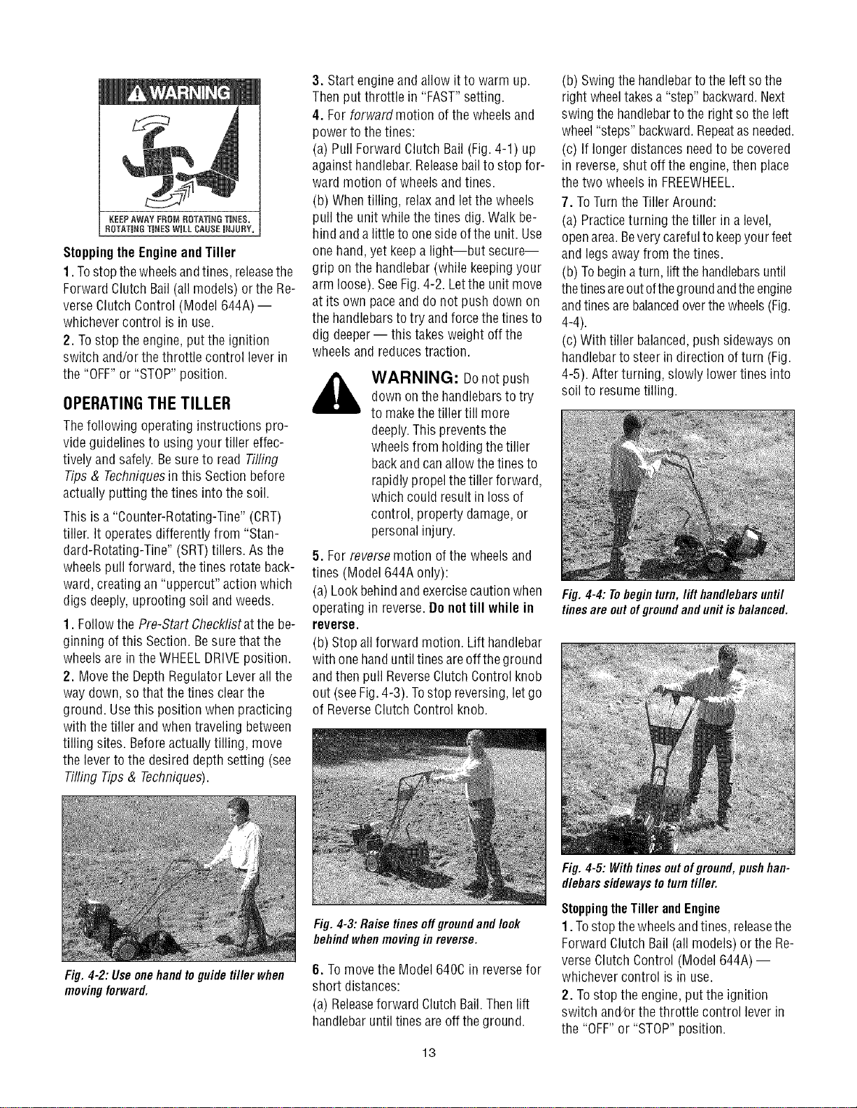
Fig.4-2:Useonehandtoguidetillerwhen
movingforward.
3. Start engineand allow it to warm up.
Thenput throttle in "FAST"setting.
4. Forforwardmotion ofthe wheels and
powerto thetines:
(a) Pull Forward Clutch Bail (Fig.4-1) up
against handlebar.Releasebail to stop for-
ward motion of wheels and tines.
(b) Whentilling, relaxand letthe wheels
pull the unit while thetines dig.Walk be-
hind anda little to onesideof the unit. Use
one hand,yet keepa light--but secure--
grip on the handlebar (while keepingyour
arm loose). SeeFig.4-2. Letthe unit move
at its own paceand do not push down on
the handlebarsto try andforcethe tines to
dig deeper-- this takesweight offthe
wheels and reducestraction.
,_ WARNING: Donotpush
down onthe handlebarsto try
to makethetiller till more
deeply.This preventsthe
wheelsfrom holding the tiller
backand canallowthe tines to
rapidly propelthetiller forward,
which could resultin lossof
control, property damage,or
personalinjury.
5. Forreverse motion ofthe wheelsand
tines (Model644A only):
(a) Lookbehindand exercisecaution when
operating in reverse.Do not till while in
reverse.
(b) Stopall forward motion. Lift handlebar
with one handuntiltines areoff the ground
andthen pull ReverseClutchControl knob
out (seeFig.4-3). Tostop reversing,letgo
of ReverseClutch Control knob.
(b) Swingthe handlebarto theleft so the
right wheeltakesa "step" backward.Next
swing the handlebarto the rightso theleft
wheel"steps" backward.Repeatasneeded.
(c) If longerdistancesneedto becovered
in reverse,shut off the engine,then place
the two wheels in FREEWHEEL.
7. ToTurnthe Tiller Around:
(a) Practiceturning the tiller in a level,
openarea.Beverycarefulto keepyour feet
and legsaway from the tines.
(b) Tobeginaturn, lift thehandlebarsuntil
thetinesareoutofthegroundandtheengine
andtinesarebalancedoverthewheels(Fig.
4-4).
(c) With tiller balanced,pushsideways on
handlebarto steer in direction of turn (Fig.
4-5). After turning, slowly lower tines into
soil to resumetilling.
Fig.4-3:Raisetinesoffgreundandlook
behindwhenmovinginreverse.
6. Tomovethe Model640Cin reversefor
short distances:
(a) Releaseforward ClutchBail.Thenlift
handlebaruntiltines are off theground.
13
Fig. 4-4: Tobegin turn, lift handlebarsuntil
tines are out of groundand unit is balanced.
Fig.4-5: Withtinesoutofgreund,pushhan-
dlebarssidewaystoturntiller.
StoppingtheTillerandEngine
1. Tostop thewheelsandtines, releasethe
Forward ClutchBail (all models) orthe Re-
verse ClutchControl (Model 644A) --
whichevercontrol is in use.
2. Tostop the engine,put the ignition
switch and/orthe throttle control leverin
the "OFF"or "STOP"position.
TILLINGTIPS& TECHNIQUES
Tilling Depths
WAHNING: Before
tilling, contact your
telephoneor utilities
companyand inquire if
undergroundequipment or
lines are usedon your
property. Donottill near
buriedelectric cables,
telephonelines, pipesor
hoses.
This isa CRT(counter-rotatingtine)tiller. Asthewheelspullforward,the tinesrotateback-
ward. Thiscreatesan "uppercut"tine actionwhich digs deeply,uprootingsoil and weeds.
Don't overloadthe engine,but dig asdeeplyaspossibleon eachpass.Onlaterpasses,the
wheelsmaytendto spinin thesoftdirt. Helpthemalongbylifting upslightlyonthehandlebar
(onehand,palm up,works mosteasily).
Avoidthetemptationto pushdownon thehandlebarsinan attemptto force thetiller to dig
deeper.Doingsotakestheweightoff the poweredwheels,causingthemto losetraction.
Withoutthewheelsto holdthetillerback,thetineswill attemptto propelthetiller backward,
towardstheoperator.(Sometimes,slightdownwardpressureonthehandlebarswill helpget
througha particularlytoughsectionofsodor unbrokenground,butin mostcasesthiswon't
benecessary.)
• Whencultivating(breakingup surfacesoilaroundplantsto destroyweeds,seeFig.4-9), ajust thetinesto dig only 1"to 2"deep.Using
shallowtilling depthshelpspreventinjury to plantswhoseroots often growclose to the surface.If needed,lift up on the handlebars
slightlytopreventthetinesfrom diggingtoo deeply.(Cultivatingona regularbasisnotonlyeliminatesweeds,it alsoloosensandaerates
thesoilfor bettermoistureabsorptionandfasterplantgrowth.)Wateringthegardenareaafewdayspriorto tillingwill maketillingeasier,
aswill lettingthenewlyworkedsoil setfor a dayor two beforemakinga final,deeptilling pass.
ChoosingCorrectWheel& TineSpeeds With experience,you will find the "just right" tilling depthandtilling speedcombination
that is bestfor yourgarden.
Settheenginethrottleleverata speedto givetheengineadequatepowerandyetallowit tooperateattheslowestpossiblespeed...atleast
until youhaveachievedthe maximumtilling depthyoudesire.Fasterenginespeedsmaybe desirablewhenmakingfinal passesthrough
theseedbedor whencultivating.Selectionofthecorrectenginespeed,in relationtothetilling depth,will ensurea sufficientpowerlevelto
do thejobwithout causingtheenginetolabor.
Letthe Tiller Dothe Work
Whiletilling, relaxandletthewheelspullthe
tiller along while the tines do the digging.
Walkon thesidethat is notyet finished(to
avoidmakingfootprints in thefreshlytilled
soil) and lightly,but securelygrip the han-
dlebarwith just onehand.
AvoidMakingFootprints
Wheneverpossible, walk on the untilled
sideoftheunitto avoidmakingfootprints in
your freshly tilled or cultivated soil. Foot-
prints causesoil compactionthat canham-
per root penetrationand contributeto soil
erosion. They can also "plant" unwanted
weed seeds back into the freshly tilled
ground.
AvoidTilling Soggy,WetSoil
Tilling wet soil often resultsin large,hard
clumpsof soil that caninterferewith plant-
ing.If time permits,wait a dayor twoafter
heavyrainsto allow the soil to dry before
tilling. Testsoil bysqueezingit intoa ball.If
itcompressestoo easily,it is toowet to till.
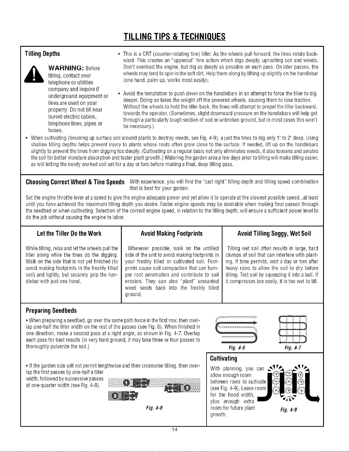
Preparing Seedbeds
•Whenpreparingaseedbed,go overthesamepathtwiceinthefirst row,thenover-
lapone-halfthetiller width ontherest ofthepasses(seeFig.6).Whenfinishedin
onedirection,makea secondpassata rightangle,as shownin Fig.4-7. Overlap
eachpassfor best results(invery hardground,it maytakethreeor four passesto
thoroughlypulverizethesoil.)
• If thegardensizewill not permitlengthwiseandthencrosswisetilling, thenover-
lapthefirst passesbyone-halfatiller
width,followedbysuccessivepasses ....................v .................................
at one-quarterwidth (seeFig.4-8). _ _
Fig. 4-8
Fig. 4-6 Fig.4-7
Cultivating
With planning, you can ==.._vp. ==_._v_
allow enoughroom _" _ (_
betweenrows to cultivate _ _
(seeFig.4-9). Leaveroom _ _
for the hood width,
plus enough extra _ _'
roomfor future plant Fig.4-9
growth.
14
TILLINGTIPS& TECHNIQUES(CON'T)
TillingOnSlopes
Readthe followingrecommendationsbeforetilling on slopes:
Ifyou mustgardenon a moderateslope,pleasefollow two very importantguidelines:
1.Tillonlyon moderateslopes,neveronsteepgroundwherefooting isdifficult (reviewsafe-
ty rulesin Section1:Safetyof this manual).
2. We recommendtilling up anddown slopesratherthan terracing.Tillingvertically on a
slopeallows maximumplantingareaandalsoleavesroomfor cultivating.
IMPORTANT:Whentilling onslopes,besurethecorrectoil levelis maintainedin theengine
(checkeveryone-halfhour of operation).Theinclineof the slopewill causethe oil to slant
awayfrom its normallevelandthis canstarveenginepartsof requiredlubrication.Keepthe
motor oil levelatthefull pointatall times!
WAHNING: Donot
operatetiller on aslopetoo
steepfor safe operation.Till
slowly and besureyou have
good footing. Neverpermit
tiller to freewheeldown
slopes.Failureto follow this
warning could result in
personalinjury.
Tilling Upand DownSlopes(VerticalTilling)
• Tokeepsoil erosionto aminimum, besureto addenoughorganicmatterto thesoil sothat it hasgoodmoisture-holdingtextureandtry
to avoidleavingfootprints orwheelmarks.
• Whentilling vertically,tryto makethefirst passuphillasthetillerdigsmoredeeplygoing uphillthanitdoesdownhill.Insoftsoilor weeds,
youmayhaveto lift the handlebarsslightlywhilegoing uphill.Whengoingdownhill, overlapthefirst passby aboutone-halfthewidth of
thetiller.
Clearingthe Tines
Thetineshavea self-clearingactionwhicheliminatesmosttanglingofdebrisinthe
tines.However,occasionallydrygrass,stringystalksortoughvinesmaybecometan-
gled.Followtheseproceduresto helpavoidtanglingandto cleanthetines,if neces-
sary.
•Toreducetangling,setthedepthregulatordeepenoughtogetmaximum"chopping"
actionasthetines chopthe materialagainsttheground.Also,try to till undercrop
residuesor covercropswhiletheyaregreen,moistandtender.
• Whiletilling,try swayingthehandlebarsfrom sideto side(about6"to 12").This
"fishtailing"actionoftenclearsthetinesofdebris.
• Iftanglingoccurs,lift thetinesoutofthesoilandrunthetiller in reverse(if unitis
equippedwithpoweredreverse)forafewfeet.Thisreversingactionshouldunwinda
gooddealofdebris.
• It may benecessaryto removethe debris by hand(a
pocketknifewill helpyou to cut awaythe material). Be
sure to stopthe engineand disconnect the sparkplug
wire beforeclearing the tines by hand.
WARNING: Beforeclearing the
tines byhand,stop the engine,allow all
moving partsto stop anddisconnect the
spark plug wire. Removethe ignition key
on electric start models.
Failureto follow this warning could result
in personalinjury.
Loading andUnloadingtheTiller
,_ WARNING: Loadingand
unloadingthetillerintoavehicleis
potentiallyhazardousandwedon't
recommenddoingsounless
absolutelynecessary,asthiscould
resultinpersonalinjuryor
propertydamage.
However,ifyoumustloador
unloadthetiller,followthe
guidelinesgivennext.
•Beforeloadingor unloading,stoptheengine,
waitfor allpartsto stopmoving,
disconnectthesparkplugwireandlettheen-
gineandmufflercool.
•Thetilleristooheavyandbulkytolift safely
byoneperson.Twoor morepeopleshould
sharetheload.
• Use sturdy ramps andmanually (engineshut
off) roll the tiller into and outof the
vehicle. Two or morepeople areneededto do
this.
• Theramps mustbestrong enoughto support
the combined weight of the tiller and any han-
dlers. Theramps should provide good traction
to prevent slipping; they shouldhave siderails
to guidethe tiller along the ramps; and they
should havealocking deviceto securethemto
the
vehicle.
• Thehandlersshouldwearsturdyfootwearthat
will helpto preventslipping.
• Positionthe loading vehicle sothat the ramp
angleis as flat as possible(the less inclineto
the ramp,the better). Turnthe
vehicle'sengineoff and apply its parking brake.
• When going up ramps, stand in the
normal operating position and pushthe tiller
ahead of you. Havea person at each sideto
turn the wheels.
• When going down ramps, walk backward
with the tiller following you. Keepalertfor any
obstacles behindyou. Positiona personat
eachwheel to control the speedof the tiller.
Nevergo down rampstiller-first, asthe tiller
could tip forward.
• Placewooden blocks on the downhill side of
the wheels if you needto stop the tiller from
rolling down the ramp.Also, use the blocks to
temporarily keepthe tiller in place onthe
ramps (if necessary),andto chockthe wheels
in place after the tiller is in the vehicle.
• After loadingthe tiller, prevent it from rolling
byengaging thewheels in the WHEELDRIVE
position. Chockthe wheelswith blocksand se-
curelytie the tiller down.
15
TILLINGTIPS& TECHNIQUES(CON'T)
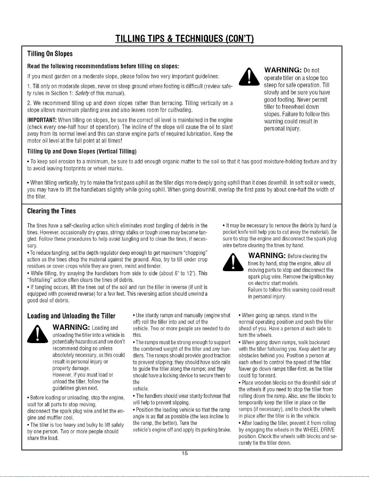
TerraceGardening(continued)
• Tocreateaterrace,startatthe top of the slopeand work down. Gobackand
forth acrossthefirst rowasshown in Fig.4-10.
• Eachsucceedinglowerterraceis startedby walking belowthe terraceyou're O m_
preparing.Foraddedstability ofthetiller,alwayskeeptheuphillwheelinthesoft,
newlytilled soil. Donottill the last 12"or moreof thedownhill outsideedgeof
eachterrace.Thisuntilledstrip helpspreventstheterracesfrom breakingapart
andwashingdownhill. It alsoprovidesawalkingpathbetweenrows. _, REPEAT
Fig. 4-10
LOADINGAND UNLOADING
THE TILLER
,_ WARNING: Loadingand
unloading thetiller into a
vehicleis potentially hazardous
andwedon't recommenddoing
so unlessabsolutelynecessary,
asthis could result in personal
injury or property damage.
However,if you must load or
unloadthe tiller, follow the
guidelinesgivennext.
• Beforeloading or unloading,stop the en-
gine,wait for all parts to stop moving,
disconnect the spark plug wire and letthe
engineand muffler cool.
•Thetiller istoo heavyand bulky to lift
safelyby one person. Twoor more people
should sharethe load.
• Usesturdy ramps and manually (engine
shut off) roll thetiller into and out of the
vehicle.Twoor more peopleare neededto
do this.
• Theramps must bestrong enoughto
support the combined weight of thetiller
and anyhandlers. The rampsshould pro-
videgoodtraction to preventslipping; they
should haveside railsto guide thetiller
along the ramps; andthey should havea
locking deviceto secure them to the
vehicle.
•Thehandlersshouldwearsturdyfootwear
that will helpto preventslipping.
• Position the loading vehicle so that the
ramp angle is asflat aspossible (the less
incline to the ramp, the better). Turnthe
vehicle'sengine off and apply its parking
brake.
•When going up ramps,stand in the
normal operating position and pushthe
tiller aheadofyou. Havea person ateach
sideto turn the wheels.
•Whengoing down ramps,walkbackward
with thetiller following you. Keepalertfor
anyobstacles behind you. Position a per-
son ateachwheelto control the speedof
thetiller. Nevergo down rampstiller-first,
asthe tiller could tip forward.
•Placewoodenblocksonthedownhill side
of the wheels if you needto stop the tiller
from rolling downthe ramp. Also, usethe
blocksto temporarily keepthe tiller in
placeon the ramps (if necessary),and to
chockthe wheels in placeafter the tiller is
in the vehicle.
• After loading the tiller, preventit from
rolling byengagingthe wheels in the
WHEELDRIVEposition. Chockthe wheels
with blocksandsecurelytiethetiller down.
16
SECTION5: MAINTENANCE
WARNING: Before
inspecting, cleaningor servicing
the machine,shut off engine,
wait for all moving parts to come
to acompletestop, disconnect
spark plug wire and movewire
awayfrom spark plug. Remove
ignition keyon electricstart
models.
Failureto follow these
instructions can result in serious
personalinjury or property
damage.
MAINTENANCESCHEDULE
PROCEDURE
Checkmotor oil level
Cleanengine
Checkdrive belttension
Checknuts and bolts
Changemotor oil
Lubricatetiller
Serviceengine air cleaner system
Checkgearoil levelin transmission
Checktines for wear
Checkair pressure in tires
(if unit haspneumatic tires)
Servicespark plug
NOTES
NOTES
2,3
2,7
1,4
1,4
4,6,9
4
7
1,5
5
5
1 Checkafter first 2 hours of break-in operation.
2 Beforeeach use.
3 Every5 operating hours.
4 Every 10operating hours.
5 Every30 operating hours,
6 Changemore frequently in dusty conditions.
7 - See EngineOwner's Manual forservice
recommendations.
8 - Whichever time interval occurs firsL
g - Changeafter first 2 hours of break-in
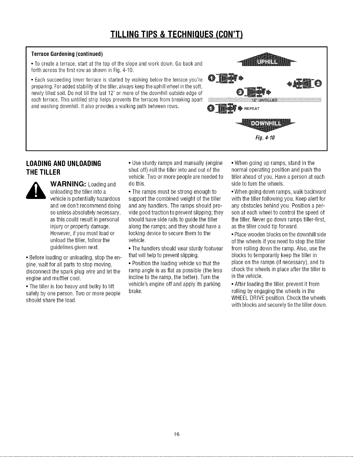
TILLER LUBRICATION
After every 10 operating hours, oil or
greasethe lubrication points shownin
Figure5-1 anddescribedbelow.
Usecleanlubricating oil (#30weight motor
oil is suitable) and cleangeneralpurpose
grease(greasecontaining a metallubricant
is preferred, if available).
• Removethe wheels,cleanthe wheelshaft
(A,Fig. 5-1) and applya thin coating of
greaseto the wheelshaft.
• Greasethe back,front andsidesof the
depthregulator lever (B, Fig.5-1).
• Removethetines andcleanthetine shaft
(C,Fig.5-1). Usea file or sandpaperto gen-
tly removeany rust, burrs or rough spots
(especiallyaround holes inshaft). Apply
greaseto ends of shaft beforeinstalling
tines.
• Oil thethreads on the handlebar height
adjustment screws and the handlebar
attaching screws (D, Fig.5-1).
Figure5-1
CHECKFOROIL LEAKS
Beforeeachuse,checkthetiller for signs of
an oil leak-- usually a dirty, oily accumu-
lation eitheron the unit or on the floor.
A little seepagearound a cover or an oil
sealis usually not a causefor alarm. How-
ever,if the oil drips overnight, then imme-
diateattention is needed.Ignoring an oil
leakcanresult in severetransmission
damage!
17
If acover is leaking,check for loose
screws. If the screws aretight, a new
gasket or oil seal may be required.
If the leakisfrom around a shaftand oil
seal, the oil sealprobably needsto be
replaced.Seeyour authorized dealeror
contact the factory for serviceor advice.
IMPORTANT:Neveroperatethe tiller if
thetransmission islow onoil.Checkthe
oil levelafter every 30 hours of
operationand wheneverthere is anyoil
leakage.
CHECKHARDWARE
Checkfor looseor missing hardwareaf-
ter every 10 operatinghoursandtighten
or replace(asneeded)beforereusing
tiller
Besureto checkthe screws underneath
thetiller hoodthat securethe transmis-
sioncoverandtheDepthRegulatorLever
to thetransmission.
CHECKTIRE PRESSURE
(Models with pneumatictires)
Checkthe air pressurein bothtires. The
air pressure should be between 15 PSi
and 20 PSi (pounds per squareinch).
Keepbothtires equally inflated to help
prevent machinefrom pulling to one
side.
TRANSMISSION
GEAROIL SERVICE
Checkthe transmission gear oil level
after every 30 hours of operationor
wheneveryou notice anyoil leak.Oper-
ating thetiller when thetransmission is
low on oil can result in severedamage.
A. To Checkthe Transmission
GearOil Level:
1. Checkthe gear oil levelwhenthe
transmission is cool. Gearoil will
expandin warm operatingtemperatures
and this expansionwill providean incor-
rect oil level reading.
2. With thetiller onlevelground, pullthe
Depth Regulator Leverall the way up.
3. Removethe oil fill plug (A,Fig. 5-2)
from thetransmission housingandlook
insidethe oil fill hole to locatethe main
driveshaft situated belowthe hole.
WARNING: Beforeinspecting, cleaningor servicing the machine,shut off engine,wait for all
moving partsto come to a completestop, disconnect spark plug wireand move wireawayfrom
spark plug. Failureto follow these instructions canresult in serious personalinjury or property
damage.
4. Thegear oil leveliscorrect ifthegear oil
isapproximately halfway upthe sideofthe
main driveshaft.
5. Ifthe gearoil levelislow, addgear oil as
described next.If the gearoil levelisokay,
securely replacethe oil fill plug.
IMPORTANT:Donot operatethe tiller ifthe
gear oil level islow. Doingso will result in
severedamageto the transmission com-
ponents.
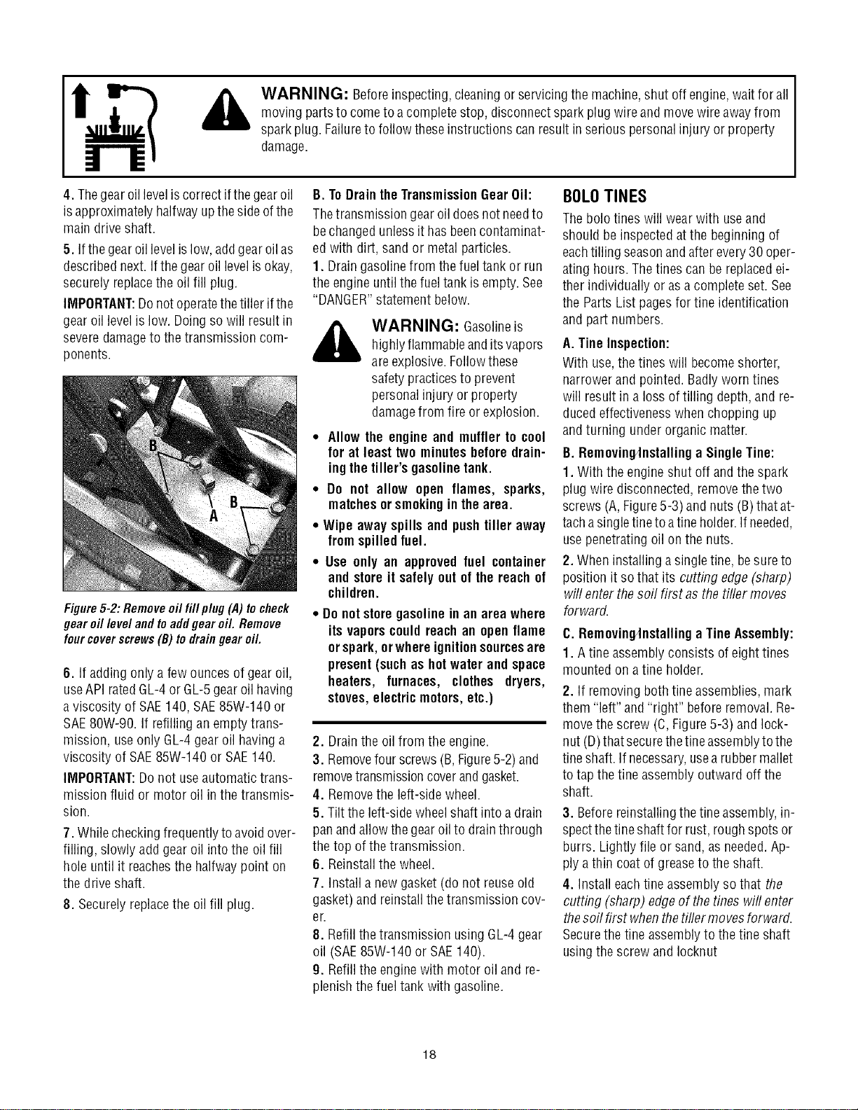
Figure5-2: Remove oil fill p/ug (,4)to check
gear oil level and toaddgear oil. Remove
fourcoverscrews(B) to draingear oil.
6. If addingonly afewouncesof gear oil,
useAPIratedGL-4or GL-5gearoil having
a viscosity of SAE140, SAE85W-140 or
SAE80W-90. If refilling an emptytrans-
mission, useonly GL-4gear oil having a
viscosity of SAE85W-140 or SAE140.
IMPORTANT:Donot useautomatic trans-
mission fluid or motor oil inthe transmis-
sion.
7. Whilecheckingfrequentlyto avoidover-
filling, slowly addgear oil into the oil fill
hole until it reachesthe halfwaypoint on
the driveshaft.
8. Securely replacethe oil fill plug.
B. ToDrain theTransmissionGearOil:
Thetransmission gear oil doesnotneedto
bechangedunless it hasbeencontaminat-
ed with dirt, sand or metalparticles.
1. Draingasolinefrom thefuel tankor run
the engine until thefuel tank is empty.See
"DANGER"statement below.
WARNING: Gasolineis
highlyflammableandits vapors
areexplosive. Followthese
safety practicesto prevent
personalinjury or property
damagefrom fire orexplosion.
Allow the engine and muffler to cool
for at least two minutesbeforedrain-
ingtheUller's gasolinetank.
Do not allow open flames, sparks,
matchesorsmokingin thearea.
Wipe away spills and pushtiller away
fromspilledfuel.
Use only an approvedfuel container
and store it safelyout of the reach of
children.
Do notstoregasolinein an area where
its vaporscould reach an openflame
orspark,orwhere ignitionsourcesare
present(suchas hot water and space
heaters, furnaces, clothes dryers,
stoves,electricmotors,etc.)
2. Drainthe oil from the engine.
3. Removefour screws (B,Figure5-2) and
removetransmissioncoverandgasket.
4. Removethe left-side wheel.
5. Tilt the left-side wheelshaft into a drain
panand allowthe gearoil to drainthrough
the top of thetransmission.
6. Reinstallthe wheel.
7. Install a newgasket (do not reuseold
gasket)and reinstall thetransmission cov-
er.
8. Refill thetransmission using GL-4gear
oil (SAE85W-140 or SAE140).
9. Refill the enginewith motor oil and re-
plenishthe fuel tank with gasoline.
BOLOTINES
Thebolo tines will wearwith useand
should be inspectedatthe beginning of
eachtilling seasonand after every30 oper-
ating hours. Thetines can be replacedei-
ther individually or as a completeset. See
the Parts List pagesfor tine identification
and part numbers.
A. Tine Inspection:
With use,the tines will becomeshorter,
narrower and pointed. Badlyworn tines
will result inaloss of tilling depth, and re-
ducedeffectivenesswhenchopping up
andturning under organic matter.
B. Removin_nstalling a Single Tine:
1. With the engine shut off andthe spark
plug wire disconnected,remove thetwo
screws (A,Figure5-3)and nuts (B)that at-
tachasingletineto atine holder.If needed,
usepenetrating oil onthe nuts.
2. When installing a singletine, besureto
position it so that its cutting edge (sharp)
will enter thesoil first asthe tiller moves
forward.
C. Removin_nstalling a TineAssembly:
1. Atine assemblyconsists of eighttines
mounted on atine holder.
2. If removingboth tine assemblies,mark
them "left" and "right" beforeremoval. Re-
move the screw (C, Figure5-3) and lock-
nut (D)that securethetineassemblytothe
tineshaft. If necessary,usea rubber mallet
to tapthe tine assembly outward off the
shaft.
3. Beforereinstallingthetine assembly,in-
spectthe tineshaftfor rust, roughspots or
burrs. Lightly file or sand, asneeded.Ap-
ply a thin coat of greaseto the shaft.
4. Install eachtine assemblyso that the
cutting (sharp) edge of thetines wifl enter
thesoil first whenthetiflermovesforward.
Securethe tine assemblyto the tine shaft
usingthe screwand Iocknut
18
,_ WARNING: Beforeinspecting, cleaningor servicing the machine,shut off engine,wait for all
moving partsto come to a completestop, disconnectspark plugwireand move wireawayfrom
spark plug. Failureto follow these instructions canresult in serious personalinjury or property
damage.
C
\
FORWARD
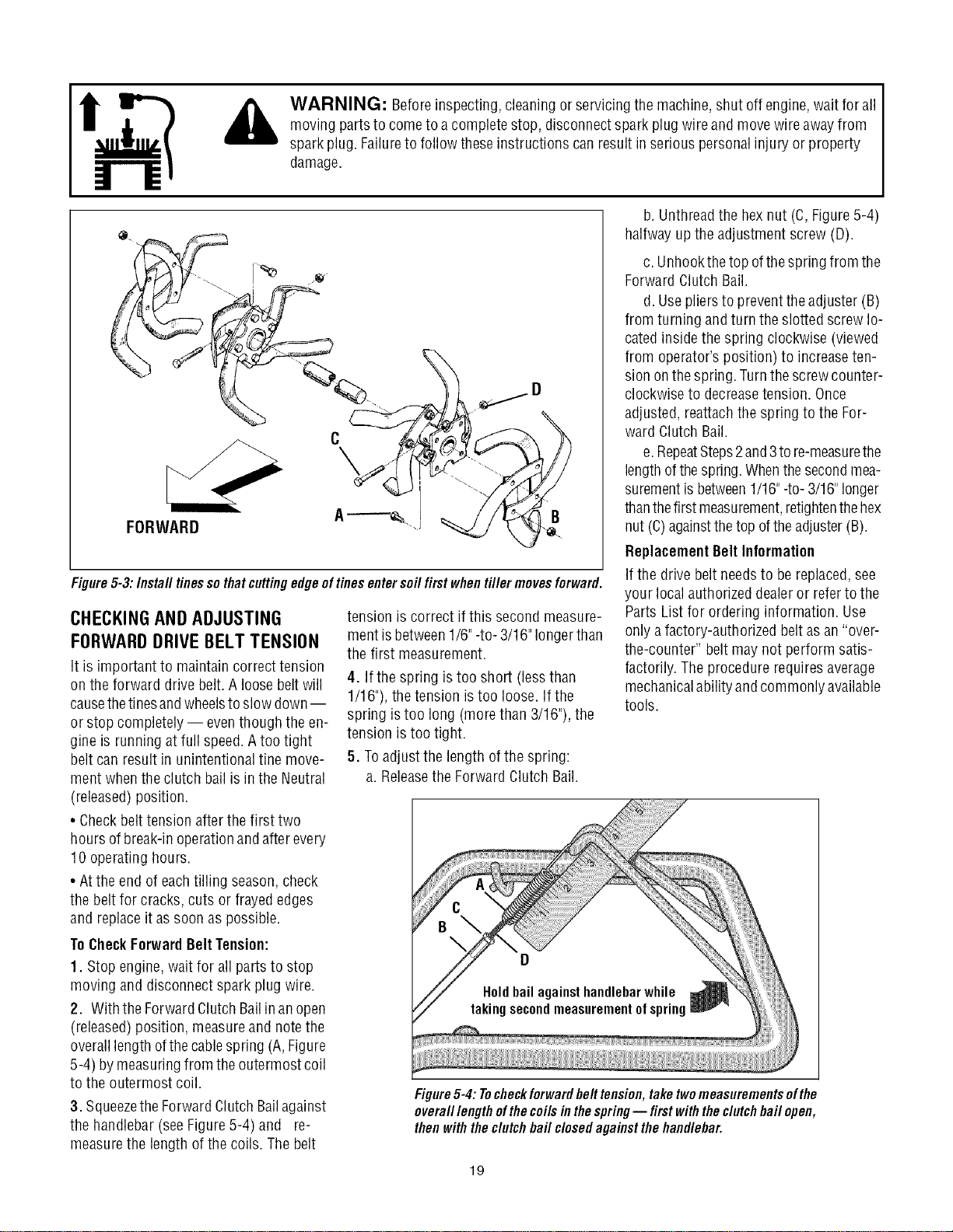
Figure5-3: Instafl tinesso that cutting edge of tines enter soft first when tiller movesforward.
CHECKINGAND ADJUSTING
FORWARDDRIVE BELT TENSION
It is important to maintain correct tension
on the forward drive belt. A loosebeltwill
causethetinesandwheelsto slow down--
or stop completely -- eventhough the en-
gine is running at full speed.A too tight
belt can result in unintentional tine move-
ment whenthe clutch bail isin the Neutral
(released)position.
• Checkbelt tension after the first two
hours ofbreak-inoperationandafter every
10 operatinghours.
• Atthe end of eachtilling season,check
the beltfor cracks,cuts or frayededges
and replaceit assoon as possible.
tension is correct if this secondmeasure-
ment isbetween1/6"-to- 3/16"longer than
the first measurement.
4. If the spring is too short (lessthan
1/16"),the tension istoo loose. If the
spring istoo long (morethan 3/16"), the
tension is too tight.
5. Toadjust the length ofthe spring:
a. Releasethe Forward Clutch Bail.
b. Unthreadthe hexnut (C,Figure5-4)
halfway up the adjustment screw (D).
c. Unhookthetop ofthe springfrom the
Forward Clutch Bail.
d. Usepliersto preventthe adjuster (B)
from turning andturn the slotted screwlo-
cated insidethe spring clockwise (viewed
from operator'sposition) to increaseten-
sion onthespring. Turnthescrewcounter-
clockwiseto decreasetension. Once
adjusted, reattachthe spring to the For-
ward Clutch Bail.
e.RepeatSteps2and3to re-measurethe
lengthofthespring.Whenthesecondmea-
surementis between1/16"-to-3/16"longer
thanthefirst measurement,retightenthehex
nut (C)againstthetop oftheadjuster(B).
ReplacementBelt Information
If the drive belt needsto be replaced,see
your local authorizeddealeror referto the
Parts List for ordering information. Use
only afactory-authorized belt asan "over-
the-counter" belt may not perform satis-
factorily. Theprocedure requiresaverage
mechanicalability andcommonly available
tools.
ToCheckForwardBeltTension:
1. Stopengine,wait for all parts to stop
moving and disconnect spark plug wire.
2. With the ForwardClutchBailinan open
(released)position, measureand notethe
overalllengthofthecablespring (A,Figure
5-4) by measuringfrom the outermost coil
to the outermost coil.
3. SqueezetheForwardClutchBailagainst
the handlebar(seeFigure5-4) and re-
measurethe length of the coils. Thebelt
Figure5-4: Tocheckforwardbelt tension,taketwomeasurementsofthe
overa///engthof thecoils inthespring-- first withthedutch bail open,
thenwith thedutch bail closedagainstthe handlebar.
19
,_ WARNING: Beforeinspecting, cleaningor servicing the machine,shut off engine,wait for all
moving partsto come to a completestop, disconnectspark plugwireand move wireawayfrom
spark plug. Failureto follow these instructions canresult in serious personalinjury or property
damage.
FORWARDCLUTCH
BAIL ADJUSTMENT
If the Forward Clutch Baildoes notfunc-
tion properly,first checkthat the forward
drive belt is adjusted properly (see Check-
ing andAdjusting Forward Drive Belt Ten-
sion). If this failsto correct the problem,
contact Troy-Bilt LLCor your authorized
dealerfor serviceadvice.
CHECKINGANDADJUSTINGRE-
VERSEDRIVEBELTTENSION
(Model644A only)
It is important to maintain correct tension
on the reversedrive belt. A loosebeltwill
causethetines andwheelsto slow down-
or stop completely - eventhough the en-
gine is running at full speed.
Whencheckingbelttension, alsocheckthe
belt for cracks, cuts or frayed edgesand
replaceit as soonas possible.
• Checkbelt tension after the first two
hours ofbreak-inoperationandafter every
10 operatinghours.
ToCheckReverseBeltTension:
1. Stopengine,wait for all parts to stop
moving and disconnect spark plug wire.
2. Removescrew in plastic beltcover and
slide beltcover (which is attachedto for-
ward clutch cable) out of the way.
3. Haveanassistant pull the Reverse
Clutch Control knob all the way out and
hold it inthat position. Measurethelength
of the cablewire betweenthe end of the
threadedcableadjuster (A,Figure5-5) and
the end of the Z-fitting (B)to which the ca-
ble wire is attached.
4. Thebelttension is idealif the cablewire
lengthmeasuresbetween1/8"to 1/4".If it is
lessthan 1/8"(andif there isno reverseac-
tion whenthe tiller is running),thenmake
the following adjustments
NOTE:Ifthe lengthis morethan 1/4",noad-
justment isneeded--as long asthe reverse
actionfunctions properly.
5. Releasethe ReverseClutchControl
knob.andthen unthreadthe inner jam nut
(C, Figure5-6) oneto two turns. Pull the
threaded cableadjuster (A, Figure5-6) to
the left untilthe innerjam nut (C)touches
the bracket.
6. Preventthe inner jam nut (C)from turn-
ing and tighten the outer jam nut (D)
againstthe bracket. Preventthe outer jam
nut (D)from turning and tighten the inner
jam nut (C)againstthe bracket.
7. Measurethe gap by repeatingStep3.
Readjustasneededby repeatingSteps 5
and 6.
8. Reinstallthe belt cover.
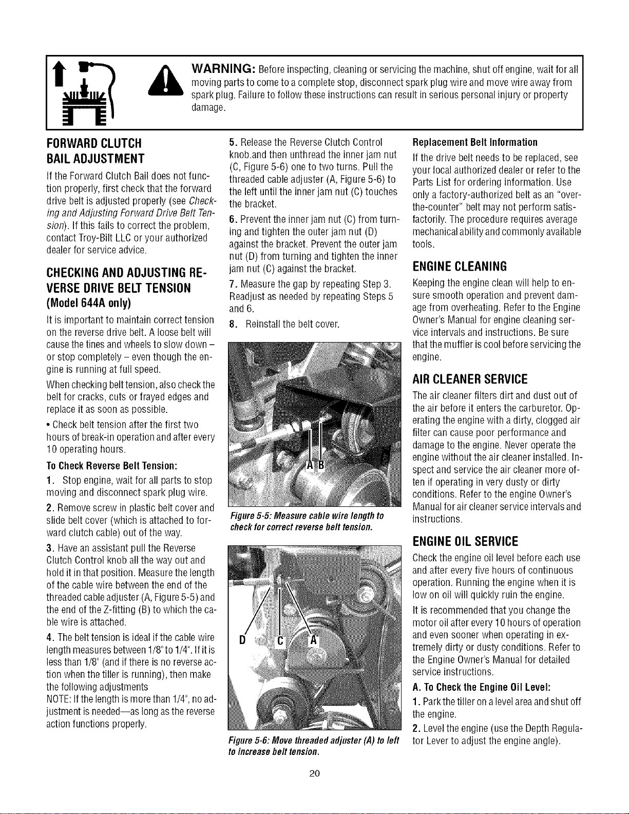
Figure5-5: Measure cable wire lengthto
checkforcorrectreversebelt tension.
Figure5-6:Movethreadedadjuster(,4)toleft
toincreasebelttension.
Replacement Belt Information
If the drive belt needsto be replaced,see
your local authorizeddealeror referto the
Parts List for ordering information. Use
only a factory-authorized belt asan "over-
the-counter" belt may not perform satis-
factorily. Theprocedure requiresaverage
mechanicalability andcommonly available
tools.
ENGINECLEANING
Keepingthe enginecleanwill help to en-
sure smooth operation and prevent dam-
agefrom overheating.Referto the Engine
Owner's Manualfor enginecleaning ser-
vice intervals and instructions. Besure
thatthe muffler iscool beforeservicingthe
engine.
AIRCLEANERSERVICE
Theair cleanerfilters dirt and dust out of
the air before it enters the carburetor.Op-
eratingthe enginewith a dirty, cloggedair
filter can causepoor performanceand
damageto the engine. Neveroperatethe
enginewithout theair cleanerinstalled. In-
spectand service the air cleanermore of-
ten if operating in very dusty or dirty
conditions. Referto the engine Owner's
Manualfor air cleanerserviceintervalsand
instructions.
ENGINEOIL SERVICE
Checkthe engine oil level beforeeachuse
and after every five hours of continuous
operation. Runningthe engine when it is
low on oil will quickly ruin theengine.
It is recommendedthat you changethe
motor oil after every 10hours of operation
and evensoonerwhen operating in ex-
tremely dirty or dustyconditions. Referto
the EngineOwner'sManualfor detailed
serviceinstructions.
A. ToChecktheEngineOil Level:
1. Parkthetiller ona levelareaandshut off
the engine.
2. Leveltheengine (usethe Depth Regula-
tor Leverto adjust the engineangle).
2O
,_ WARNING: Beforeinspecting, cleaningor servicing the machine,shut off engine,wait for all
moving partsto come to a completestop, disconnectspark plugwireand move wireawayfrom
spark plug. Failureto follow these instructions canresult in serious personalinjury or property
damage.
3. Cleanaround the oil dipstick or oil fill
tube (whicheverapplies) to prevent dirt
from falling into the crankcase.
4. Onengineswith an oil fill tube, remove
the fill capand add oil (if required) until it
reachesthetop ofthefill tube. Reinstallthe
fill cap.
5. Onengineswith a dipstick, remove it
and wipe it clean. Reinsertthe dipstick,
tighten it securely,and removeit. Add oil
asneededto bring the levelupto theFULL
mark.Wipe dipstick cleaneachtime oil
levelis checked. Donot overfill. Tighten
dipstick securely.
B. ToChangetheEngineOil:
Changethe engine oil as instructed inthe
EngineOwner's Manual.
SPARKPLUGSERVICE
Inspect andcleanor replacethespark plug
after every 100 operating hours or annual-
ly. Referto the EngineOwner'sManualfor
spark plug serviceinstructions.
In some areas,local law requiresusing re-
sistor spark plugsto suppress ignition sig-
nals. If the enginewas originally equipped
with a resistorspark plug, usethe same
type for replacement.
SPARKARRESTERSCREEN
SERVICE
If the engine muffler is equipped with a
spark arresterscreen, removeand cleanit
according to the service intervalsand in-
structions in the EngineOwner'sManual.
THROTTLELEVERADJUSTMENT
If the engine doesnot respondto various
throttle leversettings, referto the Engine
Owner'sManualfor serviceinformation or
contact your localauthorized enginedeal-
er.
WARNING: Operators
shallnottamper with theengine
governorsettings onthe
machine;the governor controls
the maximum safeoperating
speedto protect theengineand
all moving partsfrom damage
causedby overspeed.
Authorizedserviceshall be
sought if a problem exists.
CARBURETOR/GOVERNOR
CONTROLADJUSTMENTS
Thecarburetor wasadjusted atthefactory
for best operatingspeed. Referto the En-
gine Owner's Manualfor anyadjustment
information or seeyour authorizedengine
dealer.
Thegovernor controls the maximum safe
operatingspeedand protects the engine
andall moving partsfrom damagecaused
by overspeeding.Donot tamper with the
enginegovernor settings.
OFF-SEASONSTORAGE
Whenthetiller won't be usedfor an ex-
tendedperiod,prepareit for storageasfol-
lows:
1. Cleanthetiller and engine.
2. Do routinetiller lubrication and check
for looseparts and hardware.
3. Protectthe engine and perform recom-
mendedengine maintenanceby following
the storage instructions found in the En-
gine Owner's Manual.Besure to protect
the fuel lines, carburetor and fuel tank
from gum deposits byremoving fuel or by
treating fuel with a fuel stabilizer (follow
enginemanufacturer'srecommendations).
4. Store unit in aclean, dry area.
5. Neverstore thetiller with fuel in thefuel
tank in an enclosedareawhere gasfumes
could reachan open flame or spark, or
whereignition sourcesare present (space
heaters,hot water heaters,furnaces, etc.).
21
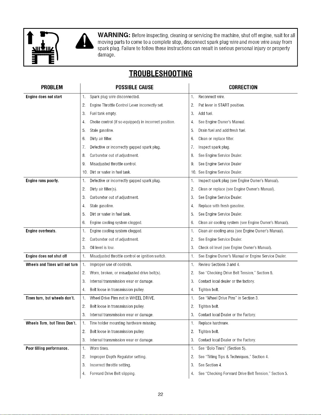
PROBLEM
Enginedoes notstart
Enginerunspoorly.
Engineoverheats.
Enginedoesnotshotoff
WheelsandTineswillnotturn
Tinesturn,butwheelsdon't,
WheelsTurn,butTinesDon't,
Poortillingperformance.
WARNING: Beforeinspecting, cleaningor servicing the machine,shut off engine,wait for all
moving partsto come to a completestop, disconnectspark plugwireand move wireawayfrom
spark plug. Failureto follow these instructions canresult in serious personalinjury or property
damage.
TROUBLESHOOTING
POSSIBLECAUSE
1. Spark plug wire disconnected
2. EngineThrottle Control Lever incorrectly set.
3. Fueltank empty.
4. Choke control (if so equipped) in incorrect position.
5. Stale gasoline.
6. Dirty air filter.
7. Defective or incorrectly gapped spark plug.
8. Carburetor out of adjustment.
9. Misadjusted throttle control.
10. Dirt or water in fuel tank.
1. Defective or incorrectly gapped spark plug.
2. Dirty air filter(s).
3. Carburetor out of adjustment.
4. Stale gasoline.
5. Dirt or water in fuel tank.
6. Enginecooling system clogged.
1. Enginecooling system clogged.
2. Carburetor out of adjustment.
3. Oil level is low.
1. Misadjusted throttle control or ignition switch.
1. Improper useof controls.
2. Worn, broken, or misadjusted drive belt(s).
3. Internal transmission wear or damage.
4. Bolt loose in transmission pulley.
1. Wheel Drive Pins not in WHEELDRIVE.
2. Bolt loose in transmission pulley.
3. Internal transmission wear or damage.
1. Tineholder mounting hardware missing.
2. Bolt loose in transmission pulley.
3. Internal transmission wear or damage.
1. Worn tines.
2. Improper Depth Regulator setting.
3. Incorrectthrottle setting.
4. Forward Drive Beltslipping.
CORRECTION
Reconnectwire.
2. Put lever in STARTposition.
3. Add fuel.
4. See EngineOwner's Manual.
5. Drain fuel and add fresh fuel.
6. Clean or replace filter.
7. Inspect spark plug.
8. See EngineService Dealer.
9. See EngineService Dealer
10. See EngineService Dealer.
Inspectspark plug (see EngineOwner's Manual).
2. Clean or replace (see EngineOwner's Manual).
3. See EngineService Dealer.
4. Replacewith fresh gasoline.
5. See EngineService Dealer.
6. Cleanair cooling system (see EngineOwner's Manual).
Cleanair cooling area (seeEngine Owner's Manual).
2. See EngineService Dealer.
3. Checkoil level (seeEngineOwner's Manual).
1. See EngineOwner's Manualor EngineService Dealer.
1. ReviewSections 3 and 4.
2. See "Checking Drive Belt Tension,"Section 5.
3. Contact local dealeror the factory.
4. Tighten bolt.
1. See "Wheel Drive Pins" in Section 3.
2. Tighten bolt.
3. Contact local Dealeror the Factory.
1. Replacehardware.
2. Tighten bolt.
3. Contact local Dealeror the Factory.
1. See "Bolo Tines" (Section 5).
2. See "Tilling Tips & Techniques," Section 4.
3. See Section 4.
4. See "Checking Forward Drive Belt Tension," Section 5.
22
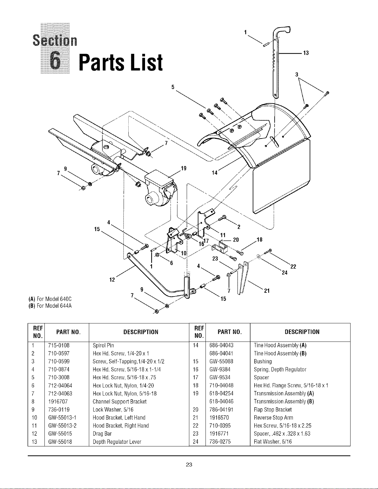
1 :::3
n
PartsList
;>
%
15
I
14
2O
m13
(A)ForModel640C
(B)ForModel644A
12
9
7
24
REF
PART NO.
NO.
1 715-0108
2 710-0597
3 710-0599
4 710-0874
5 710-3008
6 712-04064
7 712-04063
8 1916707
9 736-0119
10 GW-55013-1
11 GW-55013-2
12 GW-55015
13 GW-55018
DESCRIPTION
Spirol Pin
Hex Hd. Screw,1/4-20x 1
Screw,Self-Tapping,I/4-20 x 1/2
HexHd. Screw,5/16-18 x 1-1/4
HexHd. Screw,5/16-18 x .75
HexLock Nut,Nylon, 1/4-20
HexLock Nut,Nylon,5/16-18
ChannelSupport Bracket
Lock Washer,5/16
Hood Bracket,LeftHand
Hood Bracket,RightHand
DragBar
DepthRegulatorLever
REF
NO.
14
15
16
17
18
19
20
21
22
23
24
PARTNO.
686-04043
686-04041
GW-55088
GW-9384
GW-9534
710-04048
618-04254
618-04046
786-04191
1916570
710-0395
1916771
736-0275
DESCRIPTION
TineHoodAssembly (A}
TineHoodAssembly (B)
Bushing
Spring, DepthRegulator
Spacer
HexHd. FlangeScrew, 5/16-18 x 1
Transmission Assembly(A}
Transmission Assembly(B)
FlapStop Bracket
ReverseStop Arm
HexScrew,5/16-18 x 2.25
Spacer,.462x .328x 1.63
FlatWasher,5/16
23
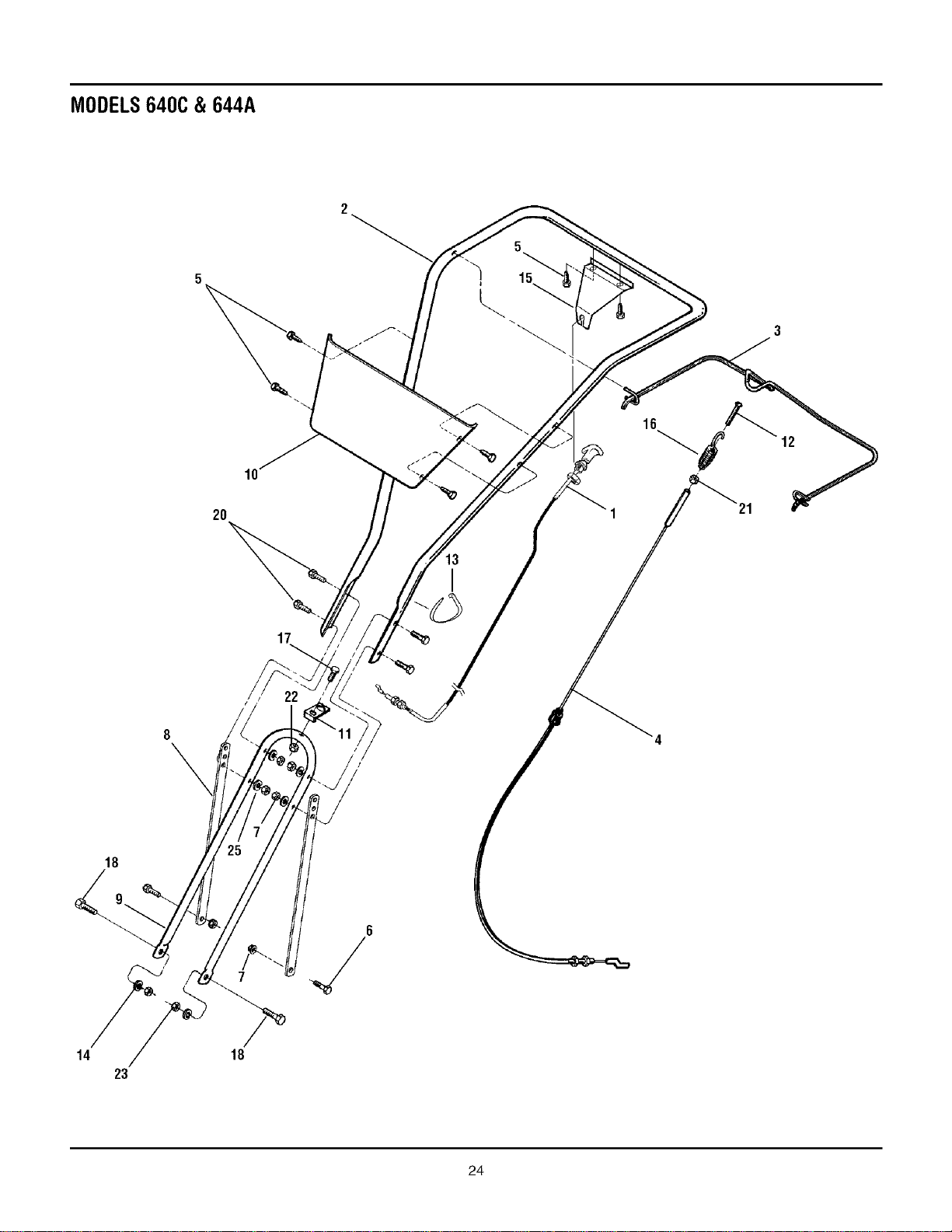
MODELS640C& 644A
5
15
2O
17
22
I
16
12
18
6
14 18
23
24
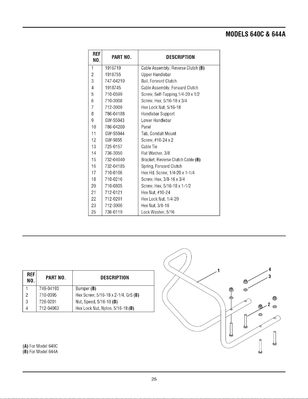
MODELS640C & 644A
REF
NO.
1
2
3
4
5
6
7
8
9
10
11
12
13
14
15
16
17
18
20
21
22
23
25
PARTNO. DESCRIPTION
1916719
1916755
747-04210
1918745
710-0599
710-3008
712-3009
786-04188
GW-55043
786-04200
GW-55044
GW-9855
725-0157
736-3050
732-04040
732-04185
710-0106
710-0216
710-0805
712-0121
712-0291
712-3000
736-0119
CableAssembly,ReverseClutch(B)
UpperHandlebar
Bail,ForwardClutch
CableAssembly,Forward Clutch
Screw,Self-Tapping,I/4-20 x 1/2
Screw,Hex,5/16-18 x 3/4
HexLock Nut,5/16-18
HandlebarSupport
Lower Handlebar
Panel
Tab, ConduitMount
Screw,#10-24 x 2
CableTie
FlatWasher,3/8
Bracket,ReverseClutch Cable(B)
Spring,Forward Clutch
HexHd.Screw,1/4-20 x 1-1/4
Screw,Hex,3/8-16 x 3/4
Screw,Hex,5/16-18 x 1-1/2
HexNut,#10-24
HexLock Nut, 1/4-20
HexNut,3/8-16
LockWasher,5/16
REF
PARTNO. DESCRIPTION
NO.
1 749-04193 Bumper(B)
2 710-0395 HexScrew,5/16-18x2-1/4,Gr5(B)
3 726-0201 Nut,Speed,5/16-18(B)
4 712-04063 HexLockNut,Nylon,5/16-18(B)
(A)ForModel640C
(B)ForModel644A
25
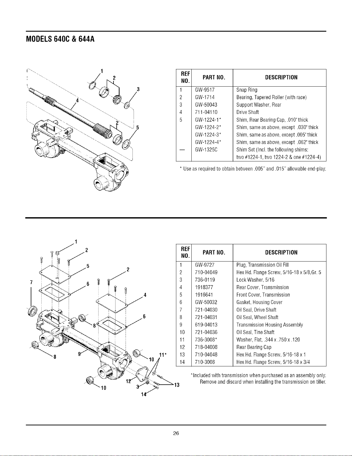
MODELS640C& 644A
REF
NO.
1
2
3
4
5
PARTNO. DESCRIPTION
GW-9517
GW-1714
GW-50043
711-04110
GW-1224-1*
GW-1224-2"
GW-1224-3"
GW-1224-4"
GW-1325C
SnapRing
Bearing,TaperedRoller(with race)
Support Washer, Rear
DriveShaft
Shim, RearBearingCap,.010"thick
Shim, sameasabove, except .030"thick
Shim, sameasabove, except.O05"thick
Shim, sameasabove, except .062"thick
Shim Set (Incl. thefollowing shims:
two #1224-1, two 1224-2 & one#1224-4)
* Useas requiredto obtain between .005" and.015" allowable end-play.
2
2
REF
NO.
1
2
3
4
5
6
7
8
9
10
11
12
13
14
PARTNO. DESCRIPTION
GW-9727
710-04049
736-0119
1918377
1916641
GW-50032
721-04030
721-04031
619-04013
721-04036
736-3008*
718-04008
710-04048
710-3008
Plug,TransmissionOilFill
HexHd.FlangeScrew,5/16-18x5/8,Gr.5
LockWasher,5/16
RearCover,Transmission
FrontCover,Transmission
Gasket,HousingCover
OilSeal,DriveShaft
OilSeal,WheelShaft
TransmissionRousingAssembly
OilSeal,TineShaft
Washer,Flat,.344x.750x.120
RearBearingCap
RexHd.FlangeScrew,5/16-18x 1
HexHd.FlangeScrew,5/16-18x3/4
*Includedwithtransmissionwhenpurchasedasanassemblyonly.
Removeanddiscardwheninstallingthetransmissionontiller.
26
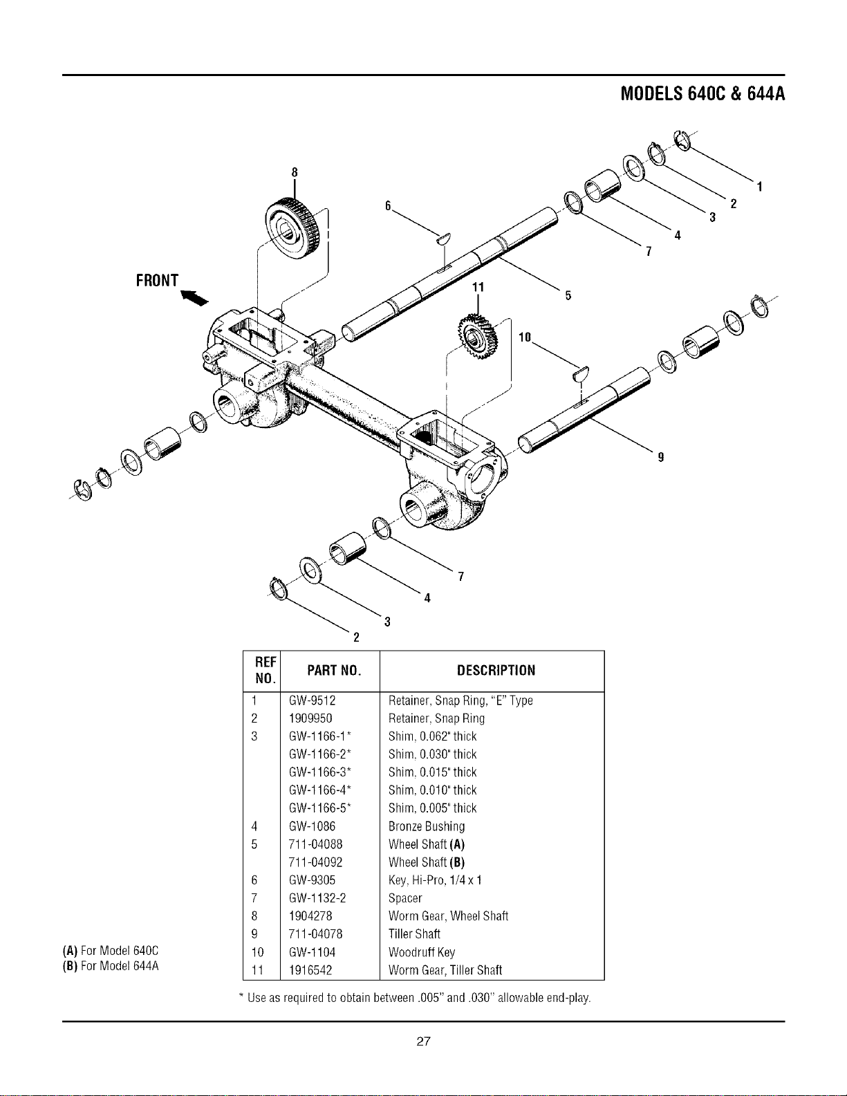
MODELS640C & 644A
FRONT
I
11
3
4
1
2
.,J
(A)ForModel640C
(B)ForModel644A
REF
NO.
1
2
3
4
5
6
7
8
9
10
11
* Useas
7
4
3
2
PARTNO. DESCRIPTION
GW-9512
1909950
GW-1166-1*
GW-1166-2"
GW-1166-3"
GW-1166-4*
GW-1166-5"
GW-1086
711-04088
711-04092
GW-9305
GW-1132-2
1904278
711-04078
GW-1104
1916542
Retainer,SnapRing, "E" Type
Retainer,SnapRing
Shim,0.062"thick
Shim,0.030"thick
Shim,0.015"thick
Shim,0.010"thick
Shim,0.005"thick
BronzeBushing
WheelShaft (A)
WheelShaft (B)
Key,Hi-Pro, 1/4 x 1
Spacer
Worm Gear,WheelShaft
Tiller Shaft
Woodruff Key
Worm Gear,Tiller Shaft
requiredto obtain between .005" and.030" allowable end-play.
27
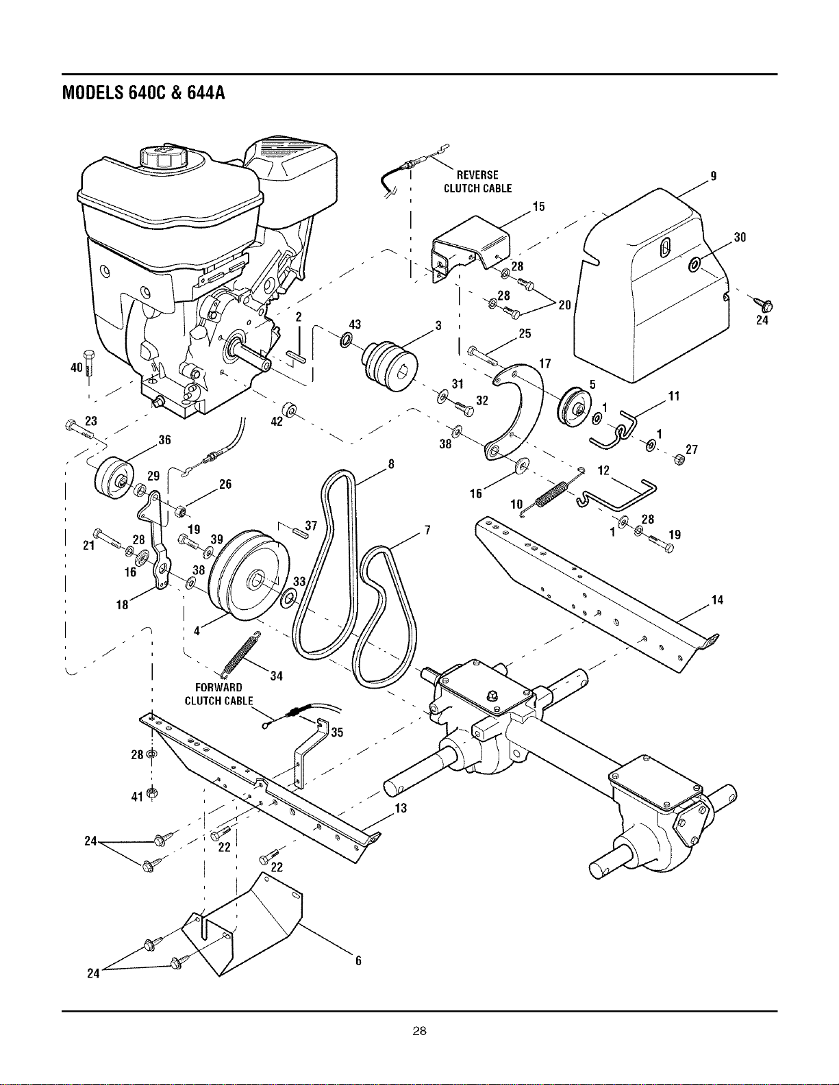
MODELS640C& 644A
8
28
9 ! I11_ 7 1 19
, FORWARD
24
24
28
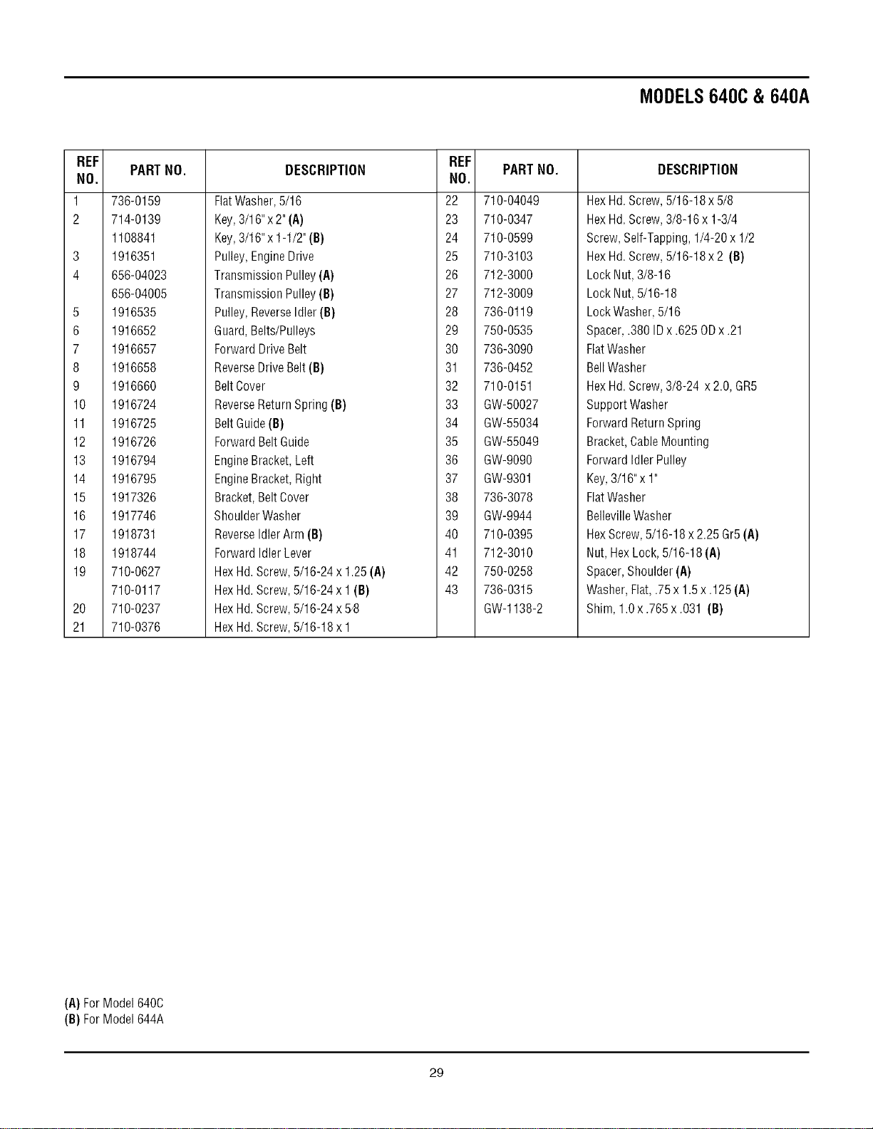
MODELS640C & 640A
REF
PART NO.
NO.
1 736-0159
2 714-0139
1108841
3 1916351
4 656-04023
656-04005
5 1916535
6 1916652
7 1916657
8 1916658
9 1916660
10 1916724
11 1916725
12 1916726
13 1916794
14 1916795
15 1917326
16 1917746
17 1918731
18 1918744
19 710-0627
710-0117
20 710-0237
21 710-0376
DESCRIPTION
FlatWasher,5/16
Key,3/16"x 2" (A)
Key,3/16"x 1-1/2"(B)
Pulley, EngineDrive
Transmission Pulley(A)
Transmission Pulley(B)
Pulley, ReverseIdler (B)
Guard,Belts/Pulleys
ForwardDriveBelt
ReverseDrive Belt(B)
BeltCover
ReverseReturn Spring (B)
BeltGuide (B)
ForwardBeltGuide
EngineBracket, Left
EngineBracket, Right
Bracket,BeltCover
Shoulder Washer
ReverseIdlerArm (B)
ForwardIdler Lever
HexHd. Screw,5/16-24 x 1.25(A)
HexHd. Screw,5/16-24 x 1(B}
HexHd. Screw,5/16-24 x 5/8
HexHd. Screw,5/16-18 x 1
REF
NO.
22
23
24
25
26
27
28
29
30
31
32
33
34
35
36
37
38
39
40
41
42
43
PART NO.
710-04049
710-0347
710-0599
710-3103
712-3000
712-3009
736-0119
750-0535
736-3090
736-0452
710-0151
GW-50027
GW-55034
GW-55049
GW-9090
GW-9301
736-3078
GW-9944
710-0395
712-3010
750-0258
736-0315
GW-1138-2
DESCRIPTION
Hex Hd.Screw, 5/16-18x 5/8
Hex Hd.Screw, 3/8-16 x 1-3/4
Screw,Self-Tapping, 1/4-20x 1/2
Hex Hd.Screw, 5/16-18x 2 (B)
Lock Nut,3/8-16
Lock Nut,5/16-18
LockWasher, 5/16
Spacer,.380 IDx .625 ODx .21
FlatWasher
BellWasher
Hex Hd.Screw,3/8-24 x 2.0,GR5
Support Washer
ForwardReturnSpring
Bracket,CableMounting
ForwardIdler Pulley
Key,3/16"x 1"
FlatWasher
BellevilleWasher
HexScrew,5/16-18 x 2.25 Gr5 (A}
Nut, HexLock, 5/16-18 (A)
Spacer,Shoulder (A)
Washer,Flat,.75 x 1.5 x.125 (A}
Shim, 1.0x .765x .031 (B}
(A)ForModel640C
(B)ForModel644A
29
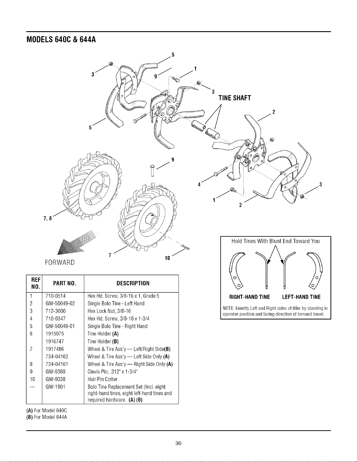
MODELS640C& 644A
3
TINE SHAFT
7_
9
FORWARD
7 "
REF
NO.
1
2
3
4
5
6
8
9
10
PARTNO. DESCRIPTION
710-0514
GW-50049-02
712-3000
710-0347
GW-50049-01
1915075
1916747
1917486
734-04162
734-04161
GW-9380
GW-9338
GW-1901
(A)ForModel640C
(B)ForModel644A
HexHd.Screw,3/8-16 x 1,Grade5
Single Bolo Tine- Left Hand
HexLock Nut, 3/8-16
HexHd. Screw,3/8-16 x 1-3/4
Single Bolo Tine- Right Hand
TineHolder(A)
TineHolder(B}
Wheel& TireAss'y -- Left/Right Side(B)
Wheel& TireAss'y -- LeftSide Only(A)
Wheel& TireAss'y-- Right SideOnly(A)
ClevisPin, .312"x 1-3/4"
Hair PinCotter
Bolo TineReplacementSet (Incl. eight
right-hand tines, eightleft-hand tines and
required hardware. (A) (B)
HoldTinesWith Blunt EndTowardYou
RIGHT-HANDTINE LEFT-HANDTINE
NOTE:Identify Left and Rightsides of tiller by standing in
operator position andfacing direction of forward travel.
3O

NOTES
31
TROY-BILT TILLER LIFETIME LIMITED WARRANTY
WHAT PRODUCT
IS COVERED
All Troy-Bilt branded rear tine walk-behind tillers with gear drive transmissions.
This warranty begins on the date of purchase and is warranted by Troy-Bilt LLC for the life of the
tiller, to the original purchaser only.
WHAT IS COVERED Troy-Bilt LLC will, at its option, repair or replace any part found to be defective in material or
BY THIS WARRANTY workmanship without charge for parts and labor
This limited lifetime warranty also applies to non-powered attachments and accessories.
Powered attachments and accessories are warranted separately by their manufacturers. Refer
to the applicable manufacturer's warranty on these items for terms and conditions.
WHAT IS NOT This warranty does not apply to parts that have been damaged by accident, alteration, misuse,
COVERED BY THIS abuse, neglect, improper maintenance, vandalism, theft, fire, water, or damage because of peril
WARRANTY or other natural disaster.
The following items are not covered after the first year of this residential use limited warranty:
belts, batteries, bushings, seals, tines, tires, wheels, paint, appearance items, and similar items
that are normally replaced through periodic maintenance.
Charges for pick-up, delivery, and service calls are not covered by this warranty.
Service completed by someone other than an authorized service dealer is not covered by this
warranty.
Parts that are not genuine Troy-Bilt LLC service parts are not covered by this warranty.
The engine is warranted separately by the engine manufacturer. Refer to the engine
manufacturer's warranty for terms and conditions.
LIMITED
COMMERCIAL
USE WARRANTY
If used for commercial, institutional, industrial, rental, or demonstrator purposes, the warranty
on the tiller is limited in duration to 90 days from the date of purchase.
This warranty does not apply to parts that have been damaged by accident, alteration, misuse,
abuse, neglect, improper maintenance, vandalism, theft, fire, water, or damage because of
peril or other natural disaster.
HOW TO OBTAIN
SERVICE
Warranty service is available, with proof of purchase, through your local authorized service
dealer. To locate a dealer in your area, consult your Yellow Pages, or contact Troy-Bilt LLC at
P.O. Box 361131, Cleveland, Ohio 44136-0019, 1-866-520-5220, or log on to our Web site at
www.troybilt.com.
The provisions set forth in this warranty provide the sole and exclusive remedy arising from the sale. Troy-Bilt LLC shall
not be liable for any incidental or consequential damage or expense of any kind, including but not limited to cost of
equipment rental, loss of profits, or costs of hiring services to perform tasks normally performed by the equipment.
Any implied warranties, including any implied warranty of merchantability or fitness for a particular purpose, shall be limited
in duration to the period of ownership by the original purchaser (and a maximum of 90 days from the date of sale if the tiller is
purchased for commercial or other non-residential use).
Some states do not allow the exclusion or limitation of incidental or consequential damages, or limitations on how long an
implied warranty lasts, so the above exclusions or limitations may not apply to you.
This limited warranty gives you specific legal rights, and you may also have other rights which vary from state to state.
For customer assistance, contact your nearest authorized dealer, or contact us at:
TROY-BILT LLC, P.O. Box 361131, Cleveland, Ohio 44136-0019, 1-866-840-6483