Loading ...
Loading ...
Loading ...
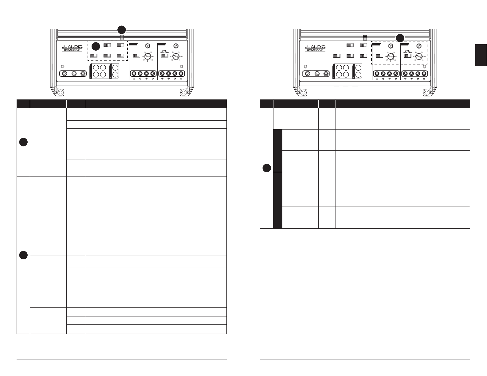
7
CONTROLS
Control (Function) Setting Description
8
Input Sens.
(adjusts each channel
pair’s input stage)
Variable
Use to match the source unit’s output voltage with the inputs of each pair of
amplier channels. See Appendix A for detailed information.
CH. 1&2
HP Filter Mode
(congures the
high-pass lter
of CH. 1&2)
O Filter defeated; passes full range of frequencies present at the inputs
HP Attentuates frequencies below the CH. 1&2 “Filter Freq. (Hz)” dial, at a rate of 12dB/octave
HP Filter Freq. (Hz)
(adjusts the high-
pass lter cuto
frequency)
Variable
Use to adjust the cuto frequency of channel 1&2’s high-pass active lter,
from 50 Hz – 500 Hz / 12dB per octave
SUB CH.
LP Filter Mode/Slope
(congures the
low-pass lter and
slope of SUB CH.)
O Filter defeated; passes full range of frequencies present at the inputs
12dB
Attentuates frequencies above the SUB CH. “LP Filter Freq. (Hz)” dial,
at a rate of 12dB/octave
24dB
Attentuates frequencies above the SUB CH. “LP Filter Freq. (Hz)” dial,
at a rate of 24dB/octave
LP Filter Freq. (Hz)
(adjusts the low-
pass lter cuto
frequency)
Variable
Use to adjust the cuto frequency of the subwoofer channel’s low-pass active lter,
from 50 Hz – 500 Hz / 12dB per octave
(
L
)
(
R
)
+12 VDC Ground Remote
Input Mode
2 Ch.
|
4 Ch.
All
|
Sub
CH. 1
CH. 2
SUB
SUB
(
L
)
(
R
)
INPUT SECTION
1&2
|
Sub
|
Sum
Preouts From Remote Level Mode
PRE-OUTS
CH. 1
(
L
)
CH. 1 & 2
SUB CH.
CH. 2
(
R
)
HP Filter Mode
HP Filter Freq. (Hz) LP Filter Freq. (Hz)
Input
Sens.
O
|
HP
Input
Sens.
Mono Subwoofer Output
Turn-On Mode
3-CHANNEL AMPLIFIER
Input Filter
Car
|
Boat
O
|
12dB
|
24dB
8
6 | JL Audio® - XDM500/3
Control (Function) Setting Description
6
Status LED
(indicates operating
status)
Flashing
Green
Amplier Powering Up, Audio Output Muted
Green On-Normal Operation, Active Audio Output
Red
On-Safe Mode, Over-Temperature Condition, Audio Output Reduced
• Reverts to normal operation when temperature returns to a safe level
Amber
(yellow)
On-Safe Mode, Over-Current Condition, Audio Output Muted
• May exhibit repetitive, audible ticking or thumping noise in the output
• Inspect for speaker/wire short circuit or low impedance
LEDs O
Amplier Turns O (unexpectedly), Low-Voltage Condition
• Occurs when battery or remote turn-on voltage drops below 10V
• Reverts to normal operation when voltage rises above 11V
7
Turn On Mode
(congures
activation method)
Remote
+12V Remote Turn-On (Preferred)
• Controlled by a switched +12V circuit or turn-on out-
put of your source unit/OEM interface
Oset
DC Oset-Sensing (Automatic)
• Turns On by detecting the presence of small DC
signal in OEM audio outputs and turns O after
the signal is removed
• Designed for high-level
(speaker) signals only
• Detects input signal from
CH. 1 (L) only
• Using DC Oset or Signal
Sensing methods will turn the
“Remote” terminal into a +12V
turn-on output.
Signal
Signal-Sensing (Automatic)
• Turns On by detecting full-range OEM audio
signals and turns OFF after the signal is removed
(within 30 seconds)
Input Filter
(congures input
lter application)
Car Select for most installations (automotive or marine)
Boat Select if experiencing interference from high-current mechanical switches/devices
Input Mode
(congures input
signal connections)
2 Ch.
Select when using CH. 1&2 inputs only
• SUB CH. signal will be the sum of CH. 1&2 signals
4 Ch.
Select when using all four inputs
• SUB CH. signal will be the sum of both left and right SUB CH. inputs
• If only one subwoofer channel signal is available, a Y-adaptor is recommended to feed
both SUB CH. inputs.
Remote Level Mode
(congures HD-RLC
operation - optional)
All Adjusts level of all channels equally
• Multiple ampliers can be controlled
from a single HD-RLC using a non-
duplex phone line splitter and multiple
phone cables.
Sub Adjusts level of subwoofer channel only
Preouts From
(congures preamp
output signals)
1&2 Same signal that is connected to CH. 1&2 inputs
Sub Same signal that is connected to the subwoofer channel inputs
Sum Summed signal, combining CH. 1&2 and subwoofer channel inputs into a stereo signal pair
CONTROLS
(
L
)
(
R
)
+12 VDC Ground Remote
Input Mode
2 Ch.
|
4 Ch.
All
|
Sub
CH. 1
CH. 2
SUB
SUB
(
L
)
(
R
)
INPUT SECTION
1&2
|
Sub
|
Sum
Preouts From Remote Level Mode
PRE-OUTS
CH. 1
(
L
)
CH. 1 & 2
SUB CH.
CH. 2
(
R
)
HP Filter Mode
HP Filter Freq. (Hz) LP Filter Freq. (Hz)
Input
Sens.
O
|
HP
Input
Sens.
Mono Subwoofer Output
Turn-On Mode
3-CHANNEL AMPLIFIER
Input Filter
Car
|
Boat
O
|
12dB
|
24dB
7
6
EN
Loading ...
Loading ...
Loading ...