Loading ...
Loading ...
4 | JL Audio® - XDM500/3
5
Connection Description Notes
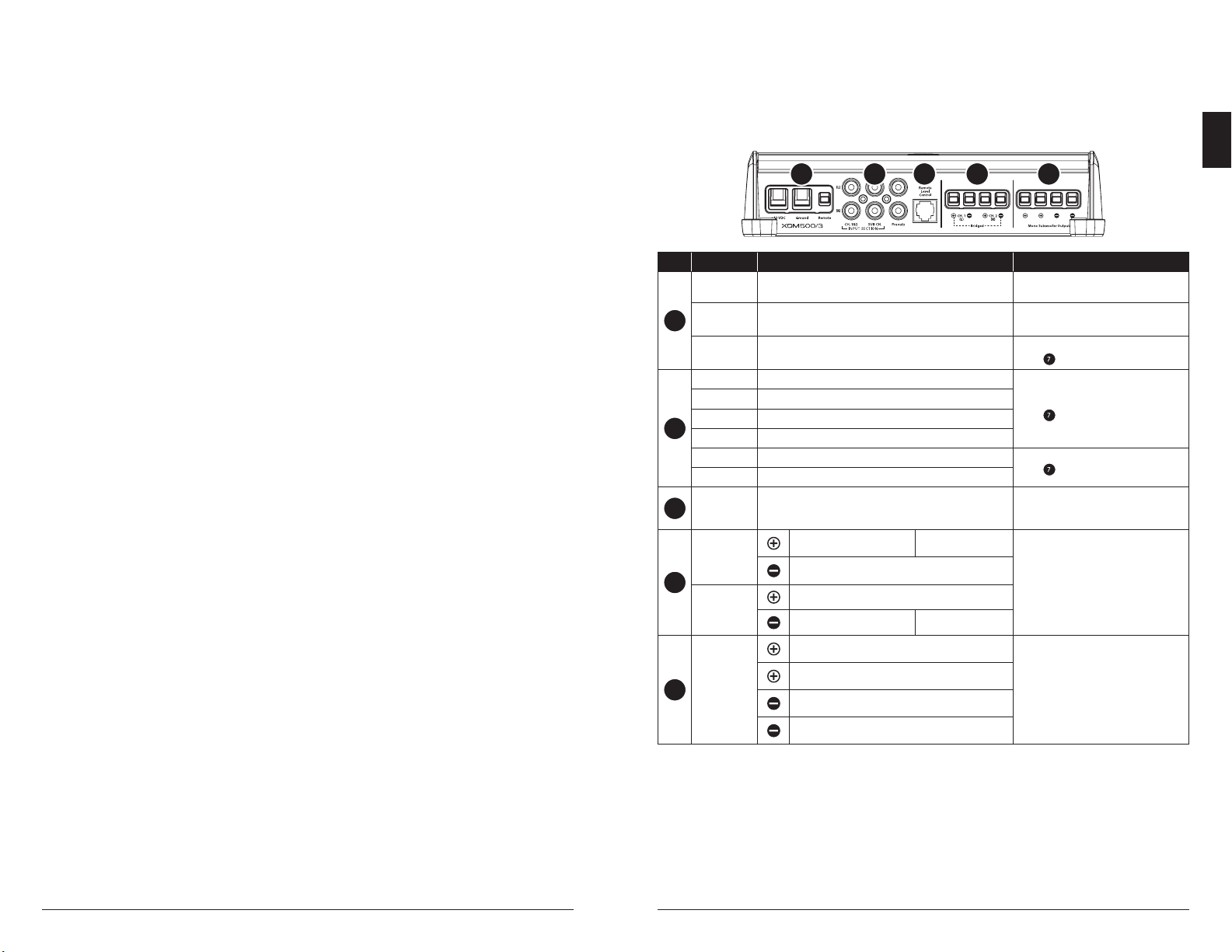
1
+12 VDC Positive (+12V) Power Connection
• 4 AWG wire (required)
• Install 50A fuse at (+) battery post
Ground Negative (GND) Ground Connection • 4 AWG wire (required)
Remote Positive (+12V) Activation Connection
• 18 – 12 AWG wire capacity
• See Turn On Mode for more info
2
CH. 1 Input Left Input Signal, Black RCA
• Accepts 200mV – 4V input voltage
• See Input Mode for more info
CH. 2 Input Right Input Signal, Red RCA
SUB CH. Input Left Subwoofer Input Signal, Black RCA
SUB CH. Input Right Subwoofer Input Signal, Red RCA
Preout 1 Left Pass-Through Preamp Signal, Black RCA
• See Preouts From for more info
Preout 2 Right Pass-Through Preamp Signal, Red RCA
3
Remote Level
Control
Remote Level Controller Connection (optional)
(HD-RLC or MHD-RLC)
• Operates as an attenuator only:
Fully counter-clockwise = Level Muted
Fully clockwise = Level Unaected
4
CH. 1 (L)
Speaker
Output
(+) Positive Speaker Output CH. 1&2 Bridged (+)
• Minimum impedance load:
Stereo mode ≥2 ohms
Bridged mode ≥4 ohms
• 16 – 8 AWG wire capacity
(–) Negative Speaker Output
CH. 2 (R)
Speaker
Output
(+) Positive Speaker Output
(–) Negative Speaker Output CH. 1&2 Bridged (–)
5
Mono
Subwoofer
Output
(+) Positive Subwoofer Output
• Both positive (+) connections are con-
nected in parallel internally
• Both negative (–) connections are con-
nected in parallel internally
• Minimum impedance load: ≥2 ohms
• 16 – 8 AWG wire capacity
(+) Positive Subwoofer Output
(–) Negative Subwoofer Output
(–) Negative Subwoofer Output
CONNECTIONS
1 2 3 4 5
INSTALLATION CONSIDERATIONS
• Installation requires appropriate tools and
safety equipment. Professional installation
is recommended.
• This product is water-resistant.
Do not submerge or subject to
high-pressure water spray.
• Before installation, turn off the audio
system and disconnect the battery
system from the audio system.
• When possible, install in a dry, well-ventilated
location that does not interfere with factory-
installed systems. If a dry environment
is not available, a location that is not
exposed to heavy splashing may be used.
• Do not install in the engine compartment,
any areas of extreme heat or where it will
be directly exposed to the elements.
• Before cutting or drilling, check for potential
obstacles behind mounting surfaces.
• Carefully route all system wiring away moving
parts and sharp edges; secure with cable ties
or wire clamps and use grommets and loom
where appropriate to protect from sharp edges.
SAFETY CONSIDERATIONS
• Only use this product with 12 volt, negative-
ground electrical systems. This product is
not certified or approved for use in aircraft.
• Mount this product securely to prevent
damage or injury in severe conditions.
• An appropriate fuse (or circuit breaker) at
the main power wire is vital for vehicle/vessel
safety and must be installed within 18 inches
(45 cm) of the positive battery connection.
• For ABYC and NMEA applications,
circuit protection is required within 7
inches (18 cm) of the battery, unless the
cable is in an enclosure or conduit.
• Listen to your audio system at
levels appropriate for operating
conditions and hearing safety.
EN
Loading ...
Loading ...
Loading ...