
OWNER’S USE AND CARE GUIDE
GUIDE D’UTILISATION ET D'ENTRETIEN
02'(/02'Ê/(
DANBY PRODUCTS LIMITED, ONTARIO, CANADA N1H 6Z9
DANBY PRODUCTS INC., FINDLAY, OHIO, USA 45840
AIR CONDITIONER
CLIMATISEUR
DAC150BBCWDB / DAC150BBUWDB
2017.01.12
This product is factory equipped with a power supply cord that has a three-pronged grounded plug. It must
be plugged into a mating grounding type receptacle in accordance with the National Electrical Code and
applicable local codes and ordinances. If the circuit does not have a grounding type receptacle, it is the
responsibility and obligation of the customer to exchange the existing receptacle in accordance with the
National Electrical Code and applicable local codes and ordinances. The third ground prong should not,
under any circumstances, be cut or removed. Never use the cord, the plug or the appliance when they show
any sign of damage. Do not use your appliance with an extension cord unless it has been checked and test-
ed by a qualifi ed electrician or electrical supplier.
IMPORTANT - GROUNDING METHOD
Ce produit arrive d’origine avec un cordon d’alimentation équipé d’une prise à trois fi ches. Il doit être
branché dans une prise avec une fi che de mise à la terre en conformité avec le Code national de l’électricité
et les codes et règles locaux applicables. Si la prise murale n’a pas de mise à la terre, il est de la
responsabilité et l’obligation du client de changer la prise existante pour la rendre conforme au Code
national de l’électricité et aux codes et règles locaux applicables. La fi che de mise à la terre ne doit pas, en
aucune circonstance, être coupée ou retirée. Si vous apercevez des signes de dommage, n’utilisez jamais le
cordon d’alimentation, la prise ou l’appareil. N’utilisez jamais l’appareil avec une rallonge sauf si elle a été
vérifi ée et testée par un électricien qualifi é ou un fournisseur de matériel électrique.
IMPORTANT - MÉTHODE POUR LA MISE À LA TERRE
AIR CONDITIONER
Owner’s Use and Care Guide ................................ 1-20
• Welcome
• Important Safety Information
• Features
• Installation Instructions
• Operation Instructions
• Care and Maintenance
• Troubleshooting
• Warranty
CLIMATISEUR
Guide d’utilisation et d’entretien..............................21-41
• Bienvenue
• Consignes de sécurité importantes
• Caractéristiques
• Consignes d’installation
• Consignes d’utilisation
• Soins et entretien
• Dépannage
• Garantie
CONTENTS
Model • Modèle
CAUTION:
Read and follow all safety rules and operating
instructions before fi rst use of this product.
AVERTISSEMENT :
Veuillez lire attentivement les consignes de
sécurité et les instructions d’utilisation avant
l’utilisation initiale de ce produit.
TABLE DES MATIÈRES
DAC150BBCWDB / DAC150BBUWDB
WELCOME
1
Welcome to the Danby family. We are proud of our quality products, and we believe in dependable service, like you will
fi nd in this Owner’s Use and Care Guide, and like you will receive from our friendly customer service department. Best of
all, you will experience these values each and every time you use your Danby appliance. That is important, because your
new appliance will be a part of your family for a long time.
For easy reference, we suggest you attach a copy of your sales slip/receipt to this page, along with the following
information, located on the manufacturer’s nameplate on the right side of the unit above the powercord.
Note the information below; you will need this information to obtain service under warranty.
To receive service, you must provide the original receipt.
NOTE: THIS UNIT IS NOT DESIGNED FOR “THROUGH-THE-WALL” INSTALLATION.
Model No:
Serial No:
Date Purchased:
NEED HELP?
Before you call for service, here are a few things you can do to
help us serve you better:
Read this Owner’s Use and Care Guide:
It contains instructions to help you use and maintain your
appliance properly.
If you received a damaged appliance:
Immediately contact the retailer (or builder) that sold you the
appliance.
Save time and money:
Check the Troubleshooting section at the end of the guide
before calling. This section helps you solve common problems
that may occur.
If you do need service, you can relax, knowing help is only a
phone call away.
WARNING
Improper connection of the grounding plug can result in risk of
fi re, electric shock and/or injury to persons associated with the
appliance. Check with a qualifi ed service representative if in doubt
that the appliance is properly grounded.
1-800-26-
(1-800-263-2629)
Important Safety Information
READ AND FOLLOW ALL SAFETY INSTRUCTIONS
FOR YOUR SAFETY: Read these instructions carefully before operating the unit.
ELECTRICAL SPECIFICATIONS
1. All wiring must comply with local and national electrical codes and must be installed by a qualifi ed electrician. If you
have any questions regarding the following instructions, contact a qualifi ed electrician.
2. Check available power supply and resolve any wiring problems BEFORE installing and operating this unit.
3. This 115V or 230/208V air conditioner uses 11.5 or less nameplate amps and may be used in any properly wired,
general purpose household receptacle. See Table 1 for specifi cations for individual branch circuit.
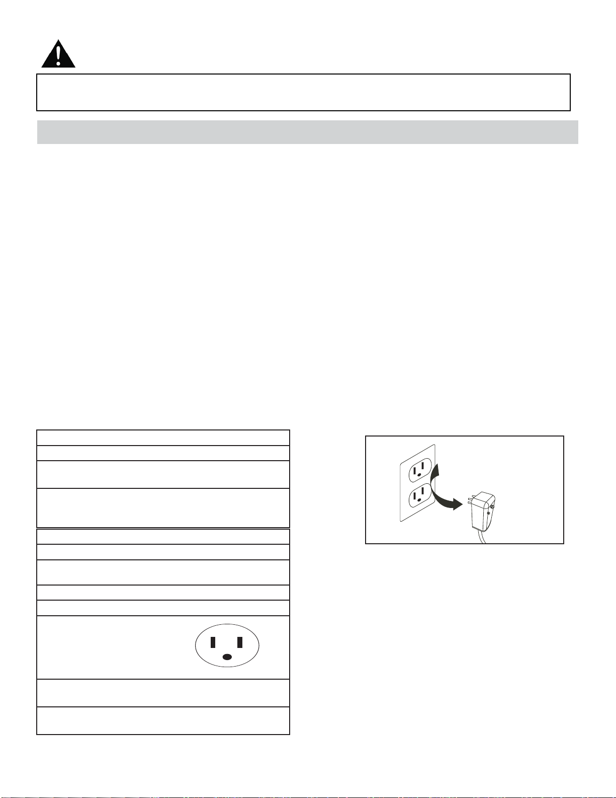
4. For your safety and protection, this unit is grounded through the powercord plug when plugged into a matching wall
outlet. If you are not sure whether your wall outlet is properly grounded, please consult a qualifi ed electrician.
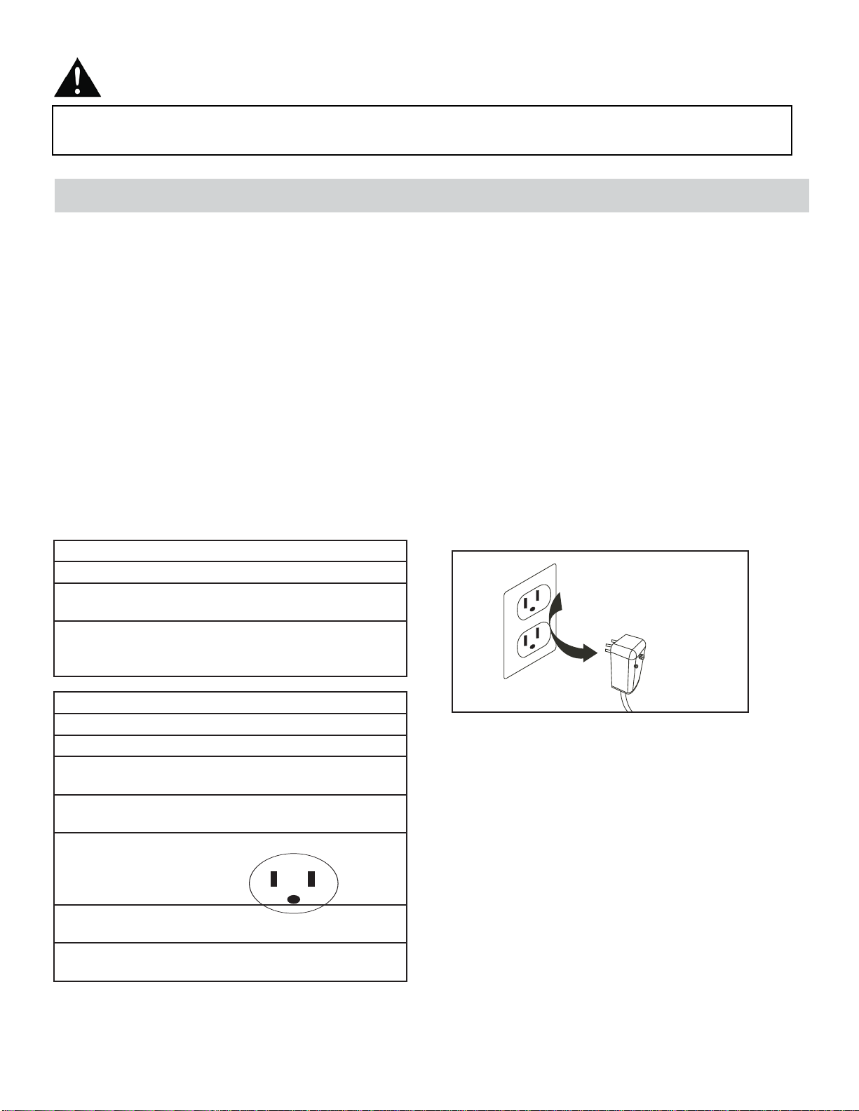
5. The wall outlet must match the 3-prong plug on the service cord supplied with the unit. DO NOT use plug adapters.
See Table 2 for receptacle and fuse information.
6. The rating plate on the unit contains electrical and other technical data. The rating plate is located on the right side of
the unit, above the powercord.
TABLE 1
Suggested Individual Branch Circuit
Nameplate Amps *AWG Wire Size
11.5 14
AWG- American Wire Guage
*Based on copper wire at 105°C (221°F) temperature
rating.
TABLE 2
Recept and Fuse Types
Model DAC150BBCWDB / DAC150BBUWDB
Rated Volts 125 240
250
Amps 15 15
30
Wall Outlet
Fuse Size 15 15
20
Time Delay Fuse Plug Type
(or Circuit Breaker)
Do not, under any
circumstances, cut,
remove, or bypass
the grounding prong.
2
Your appliance is designed to be highly effi cient in energy savings. Follow these recommendations for greater effi -
ciency.
1. Select a thermostat setting that suits your comfort needs and leave at that chosen setting.
2. The air fi lter is very effi cient in removing airborne particles. Keep the air fi lter clean at all times (usually cleaned every
2 weeks depending on indoor air quality).
3. Use drapes, curtains or shades to keep direct sunlight from penetrating and heating the room, but do not allow drapes
or curtains to obstruct the air fl ow around the unit.
4. Start your air conditioner before the outdoor air becomes hot, to avoid an initial period of discomfort while the unit is
cooling the room.
5. When outdoor temperatures are cool enough, use the FAN MODE only, on HIGH, MEDIUM, or LOW setting. This
circulates indoor air, providing some cooling comfort, and utilizes less electricity than when operating on a cooling
setting.
Important Safety Information
READ AND FOLLOW ALL SAFETY INSTRUCTIONS
FOR YOUR SAFETY: Read these instructions carefully before operating the unit.
ENERGY SAVING TIPS
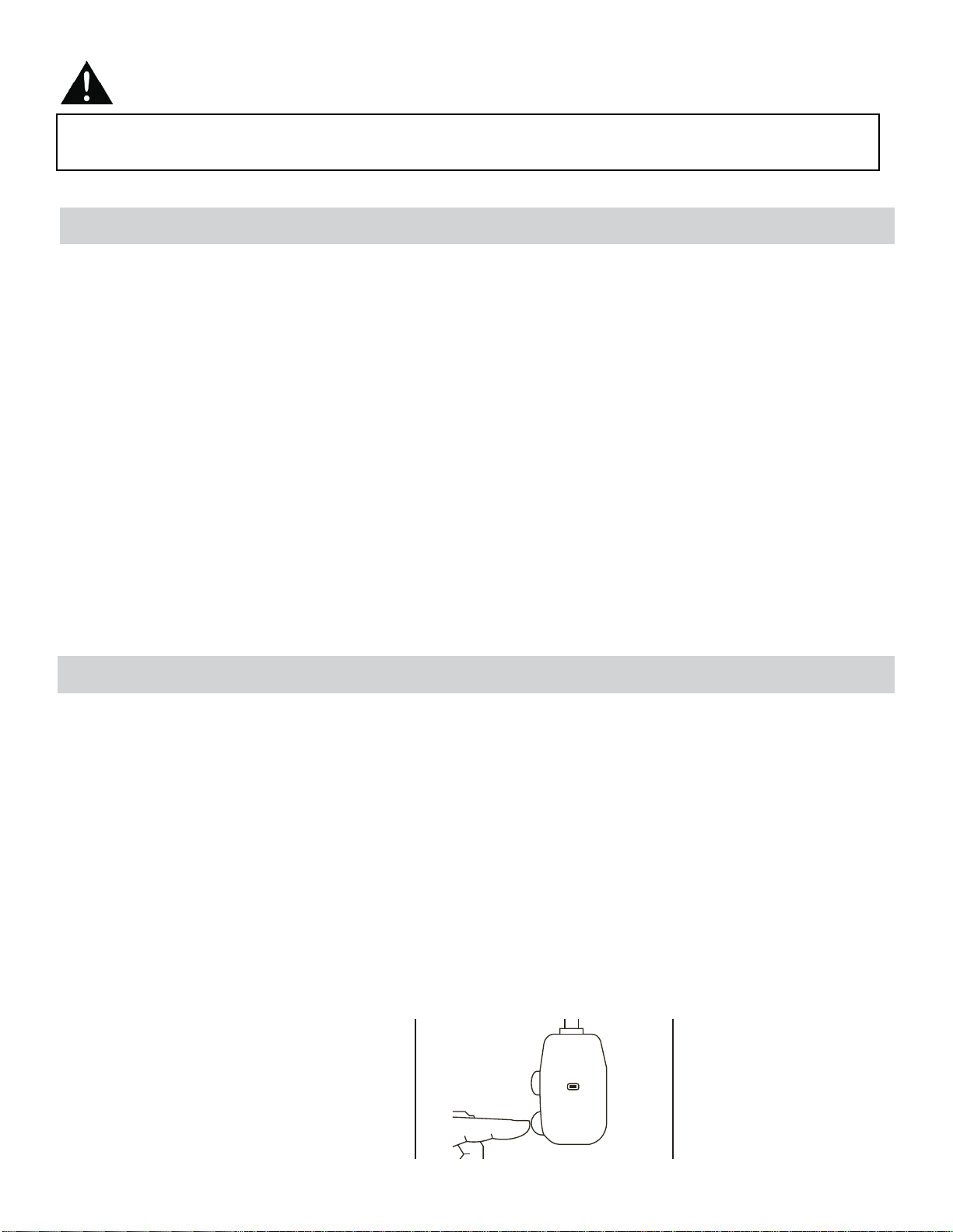
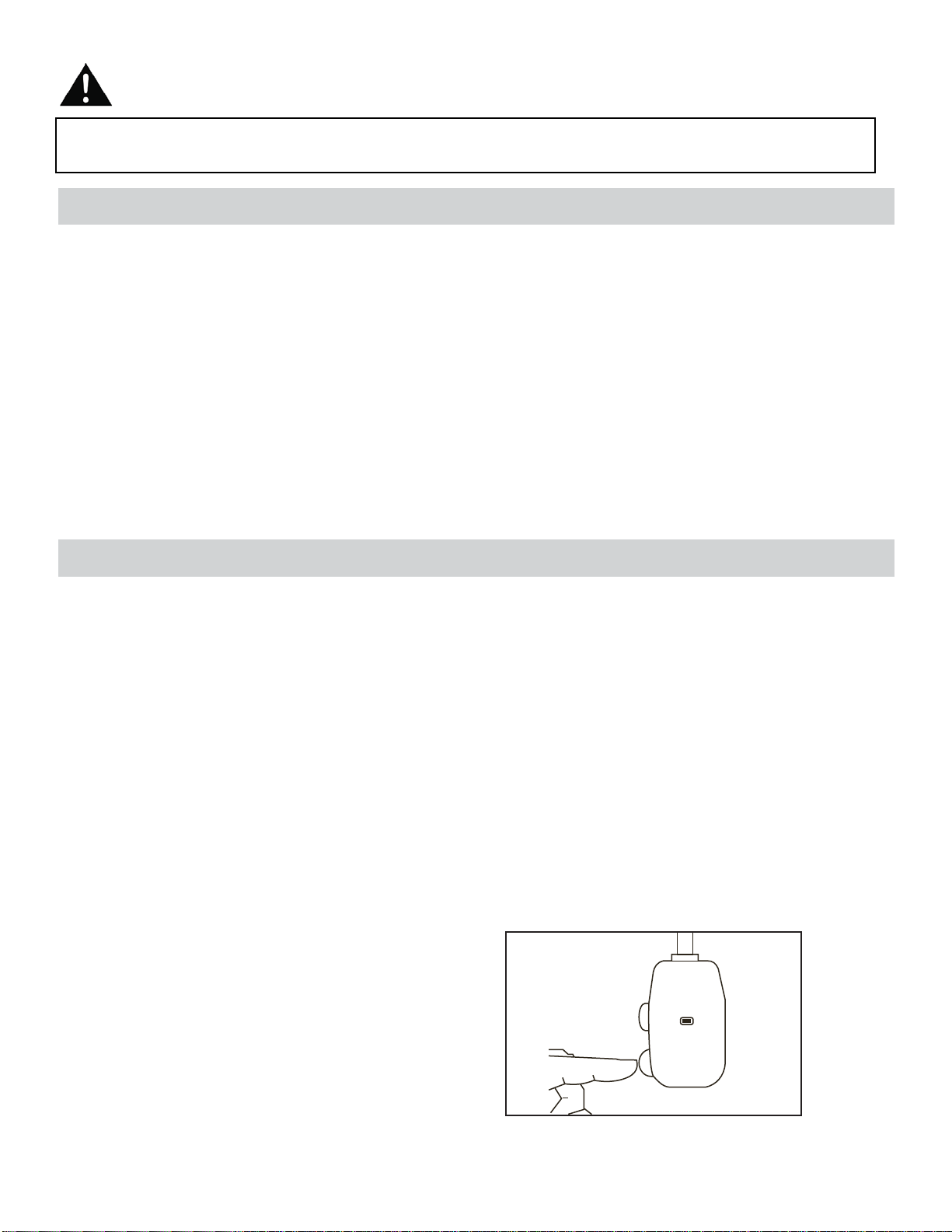
The power cord supplied with this air conditioner contains a device that senses damage to the power cord. To test if your
power cord is working properly, you must do the following:
1. Connect the power supply cord to an electrical outlet.
2. The power supply cord has two buttons located on the head of the plug. One button is marked “TEST”, and the other
is marked “RESET”. Press the “TEST” button; you will hear a click as the “RESET” button pops out.
3. Press the “RESET” button; you will hear a click as the button engages.
4. The power supply cord is now energized and supplying electricity to the air conditioner (on some products this is also
indicated by a light on the plug head).
NOTE: The power cord supplied with this air conditioner contains a current leakage detection device designed to reduce
the risk of fi re. In the event the power supply cord is damaged, it cannot be repaired and must be replaced with a new
cord from the product manufacturer.
• Under no circumstances should this device be used to turn the unit on or off.
• The “RESET” button must always be pushed in (engaged) for correct operation.
• The power supply cord must be replaced if it fails to reset when the “TEST” button is pushed in.
NOTE: Some plugs have buttons on the top.
POWER SUPPLY CORD
Plug in and press
RESET
TEST
RESET
3
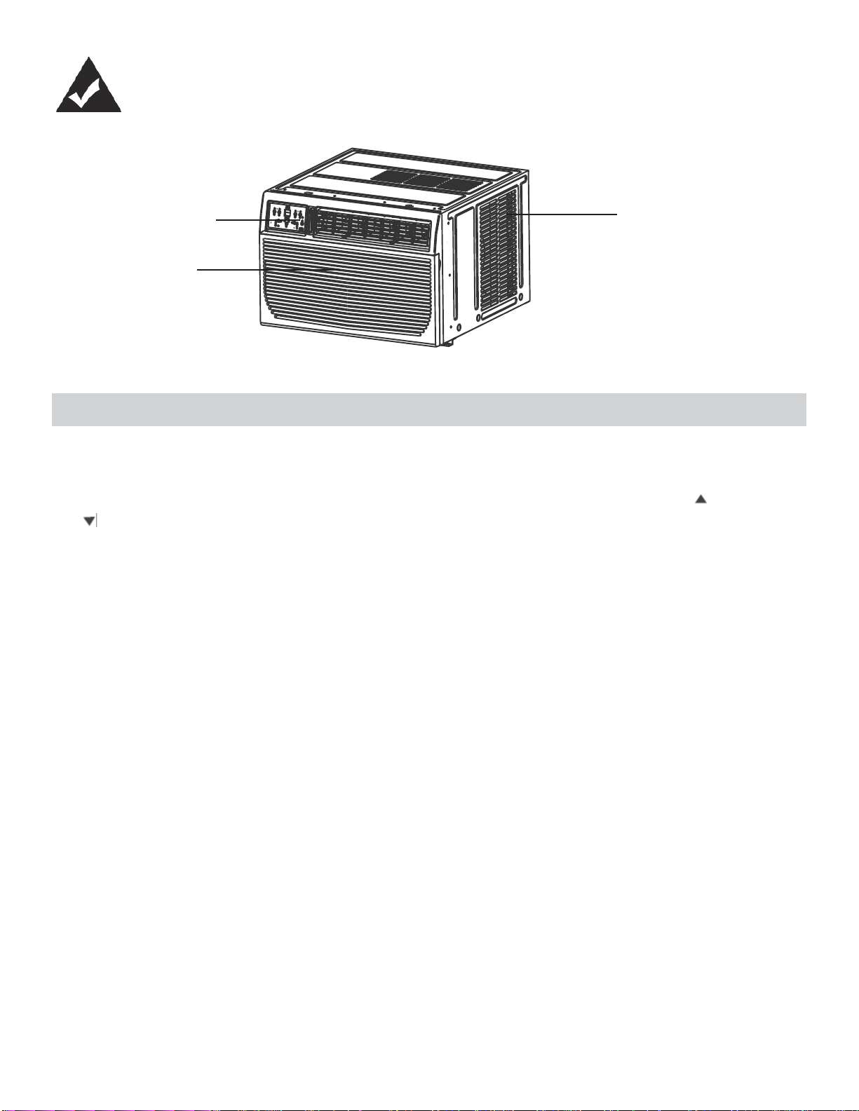
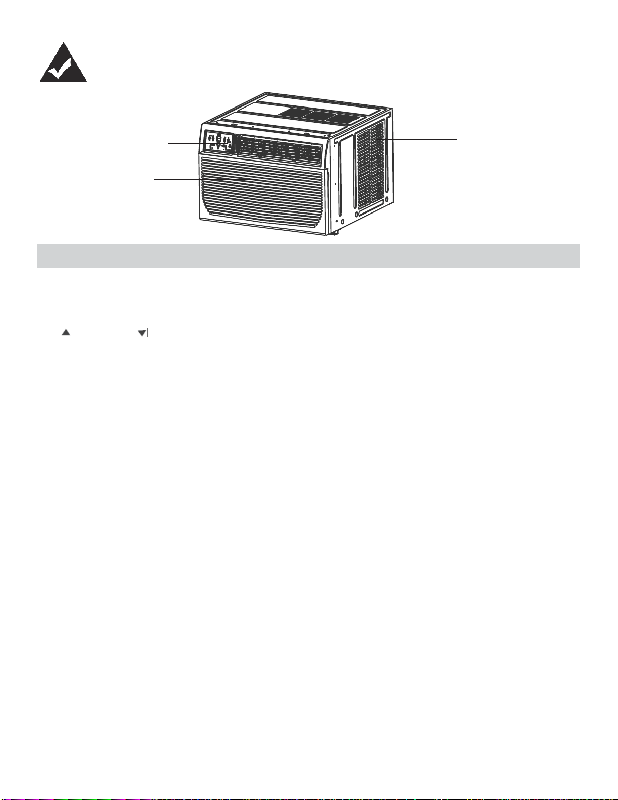
FEATURES
Control Panel
Interior Air
Inlet
Cabinet
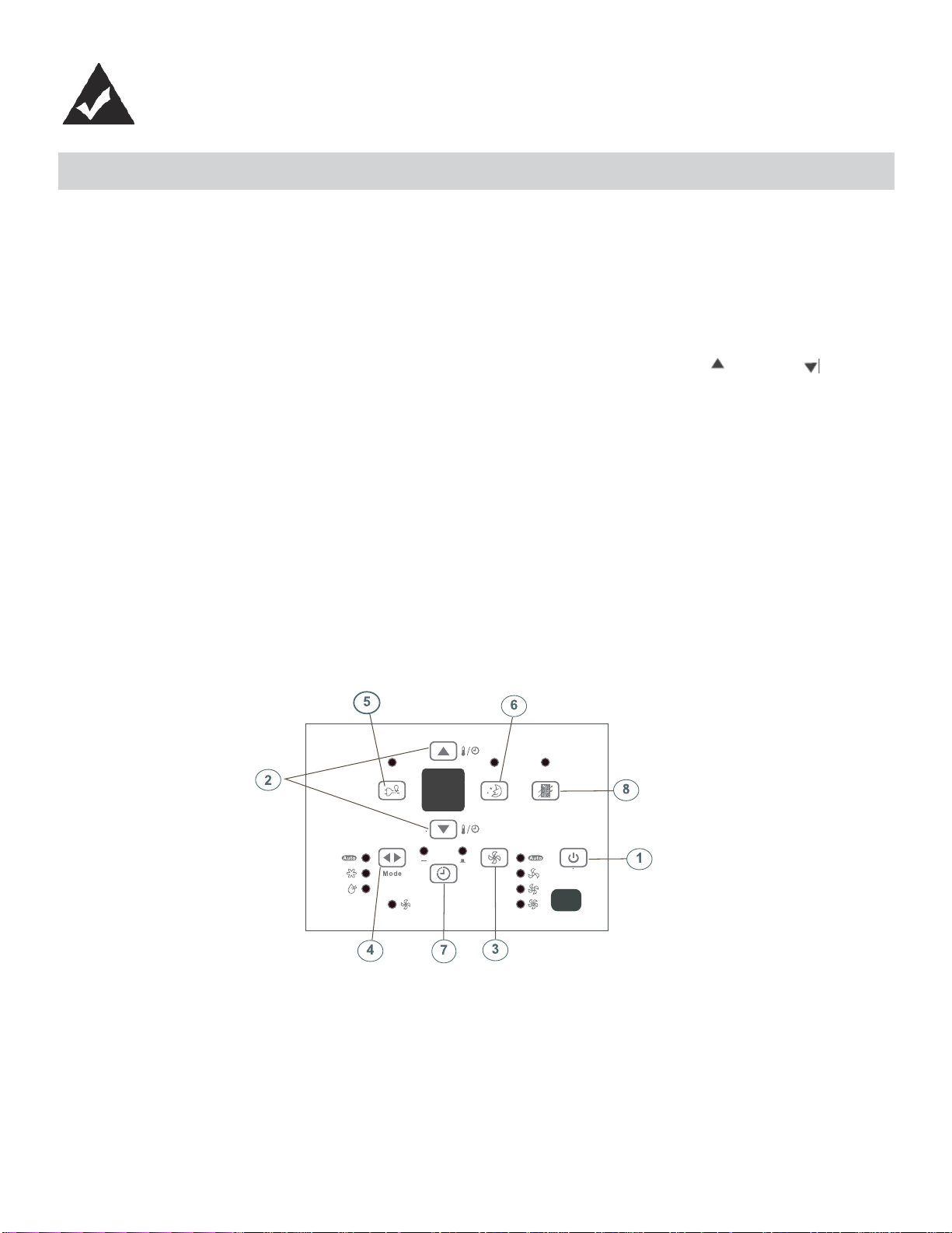
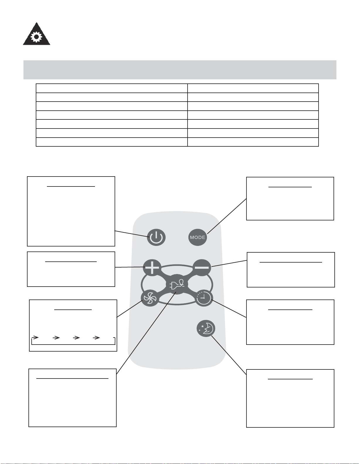
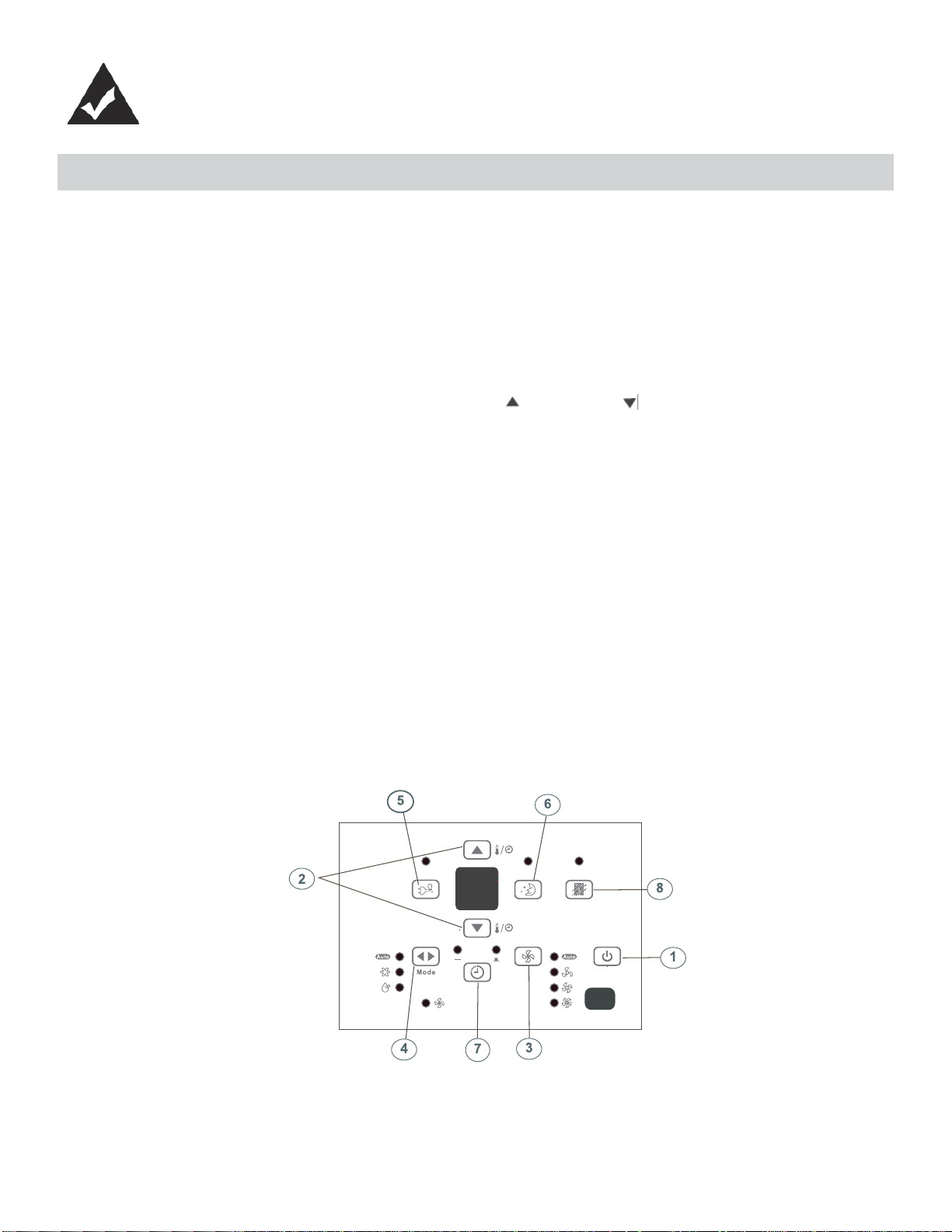
UNIT CONTROL PANEL
1. ON/OFF Button: Press to turn the unit on/off. NOTE: The unit will automatically launch the Energy Saver function
when it is in Cool, Dry and Auto modes.
2. Temperature UP/DOWN Buttons: To change the temperature setting, press or hold either the UP ( ) or DOWN
( ) button, until the desired temperature is seen on the display. This temperature will be automatically maintained
anywhere between 17°C (62°F) and 30°C (86°F). In Cooling mode, the display reads the set temperature, while in
Fan mode, the current room temperature is displayed.
3. Fan Speed Button: Select from four different fan settings: Auto, Low, Med or High. Each time the button is pressed,
the fan speed is shifted.
4. Mode Button: Allows you to scroll through and select the desired operating mode: Auto, Cool, Dry and Fan. The se-
lected mode will be denoted by the adjacent indicator light.
Operation in Auto Mode:
• Auto is a pre-set factory program that automatically defi nes the mode and fan speed, based on the set temperature
you have chosen. An example of Auto operation is as follows:
• If you would like to cool down your room, your desired / set temperature will be below the room temperature, and your
air conditioner will go into cooling mode. Once the room has reached your desired temperature, the air conditioner will
switch to Fan mode, and circulate the cooled air around the room. When the temperature in the room goes up, the
unit will switch back to cooling mode, and the Auto cycle will start again.
Operation in Dry Mode:
• Please note that in this mode you cannot set the desired humidity level, it is automatically pre-set. The fan speed in
this setting is defaulted to “low”. Since the compressor is operating in order to remove moisture from the air, you will
experience a degree of cooling as a by-product.
Operation in Fan Only Mode:
• Use this function, when cooling is not desired, such as for room air circulation, or to exhaust stale air. Remember
to open the vent during this function, but keep it closed during cooling, for maximum cooling effi ciency. In this mode
you can choose any fan speed you prefer. In Fan mode, the temperature cannot be set, and the display will read the
current room temperature.
5. Energy Saver: This is the default setting on this model. The unit will automatically cycle the fan on and off while
the compressor is not in use. The fan will continue to run for 3 minutes after the compressor shuts off. The fan then
cycles on for 2 minutes at 10 minute intervals, until the room temperature is above the set temperature. At this point,
the compressor turns back on and cooling re-starts. When the unit is in Energy Saver mode, the indicator light above
the Energy Saver button will be illuminated. You can take the unit out of Energy Saver mode by pressing the Energy
Saver button - the indicator light about the button will turn off. If you choose the non-Energy Saver option, the fan will
run continuously when the compressor is not in use.
4
UNIT CONTROL PANEL
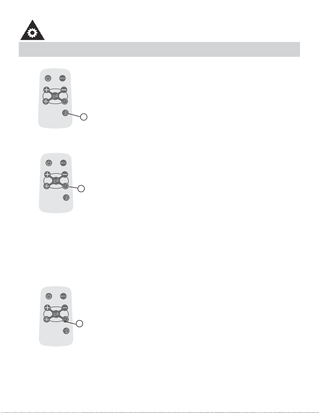
6. Sleep Button: Press the Sleep button to initiate the Sleep mode. In this mode, the selected temperature will
increase (when in cooling mode) by 1°C (2°F) one half-hour after Sleep mode has been selected. The temperature
will then increase by another 1°C (2°F) after an additional half-hour. This new temperature will be maintained for 6
hours before returning to the originally selected temperature. This ends the Sleep mode and the unit will continue to
operate as originally programmed. The Sleep mode program can be cancelled at any time during operation by
pressing the Sleep button again.
7. Timer (Auto Start / Stop Feature) Button: Pressing the Timer button will illuminate the indicator beside the word
“On”. This indicates that the Auto Start program has been initiated. Press or hold the Up ( ) or Down ( ) buttons
to change the Auto time by 0.5 hour increments, up to 10 hours, then at 1 hour increments up to 24 hours. The
control will count down the time remaining until the start of the program. The selected time will register in 5 seconds
and the system will automatically revert back to displaying the previous temperature setting. Turning the unit ON or
OFF at any time will cancel the Auto Start/Stop function.
8. Check Filter Button: This feature is a reminder to clean the air fi lter for more effi cient operation. The LED (light)
illuminates after 250 hours of operation. To reset after cleaning the fi lter, press the check fi lter button and the light
will go off.
ADDITIONAL FEATURES:
• The Cool circuit has an automatic 3 minute time delayed start if the unit is turned off and on quickly. This prevents
overheating of the compressor and possible circuit breaker tripping. The fan will continue to run during this time.
• The control will maintain any set temperature within 2°, between 15°C-32°C (60°F - 90°F).
• The control is capable of displaying temperature in Celsius (°C) or Fahrenheit (°F). To convert from one to the other,
press and hold the UP and DOWN Temp./Timer buttons at the same time for 3 seconds.
5
FEATURES
FEATURES
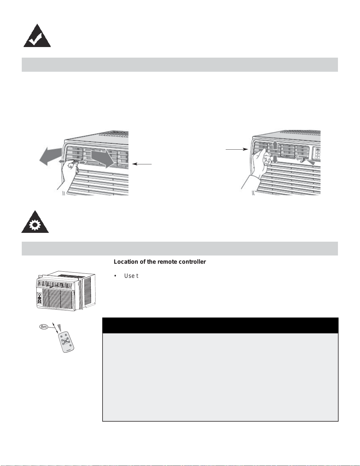
ADJUSTING AIR FLOW
The 4-way air directional louvers allow you to direct the air fl ow up or down and left or right throughout the room as needed.
RECOMMENDATION: When cooling, adjust blades to face upward. If you orient the air fl ow blades downward and the unit
operates in cool mode for long periods of time, dew may form and drip from the surface of the blades.
Up or Down
Left or Right
OPERATING INSTRUCTIONS
USING THE REMOTE CONTROL
ä
â
i
ä
Å
Å
à
ä
~
Ä
è
Ä
à
ã
ê
ã
è
Ä
à
ã
~
ä
í
â
é
í
Ñ
â
Ç
Å
{
â
è
Ñ
à
Ä
ç
é
á
Ä
Ä
ã
8m
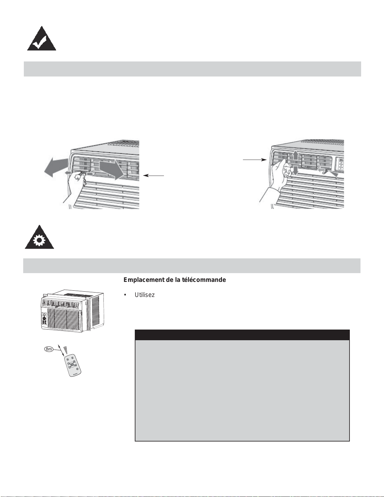
Location of the remote controller
• Use the remote controller within a distance of 8 meters from the appliance, point-
ing it towards the receiver. Reception is confi rmed by a beep.
• The air conditioner will not operate if curtains, doors or other materials block
the signals from the remote controller to the indoor unit.
• Prevent any liquid from falling into the remote controller. Do not expose the
remote controller to direct sunlight or heat.
• If the infrared signal receiver on the indoor unit is exposed to direct sunlight,
the air conditioner may not function properly. Use curtains to prevent the
sunlight from falling on the receiver.
• If other electrical appliances react to the remote controller, either move these
appliances or call the service depot.
CAUTION
6
REMOTE CONTROLLER SPECIFICATIONS
Model R15B
Rated Voltage 3.0V
Battery Type Button cell: CR2025
Battery Quantity 1pcs
Lowest Voltage of CPU Emitting Signal 2.0V
Signal Receiving Range 8m
Environment -8°C to 60°C (18°F to 140°F)
Model / Modèle :
R15B
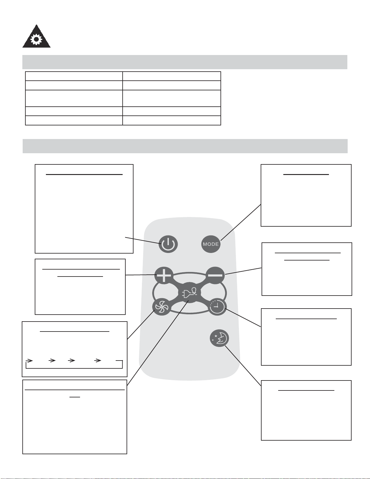
ON/OFF BUTTON
Operation starts when this button
is pressed and stops when the
button is pressed again. NOTE:
The unit will automatically launch
the Energy Saver function when
it is in Cool, Dry, and Auto modes
(Only Auto-Cool and Auto-Fan
modes.)
TEMP UP BUTTON
Push this button to increase the
temperature setting in 1°C (1°F)
increments to 30°C (86°F) .
FAN BUTTON
Used to select the fan speed in
four steps:
LOW MED HIGH AUTO
ENERGY SAVER BUTTON
Press this button to activate the
energy saving mode. Press it
again to stop the function. This
function is available in COOL,
DRY, and AUTO modes (only
Auto-cool and Auto-fan modes).
MODE BUTTON
Each time you press this button,
a mode is selected in a sequence
that consists of AUTO, COOL,
DRY, FAN, and back to AUTO.
TEMP DOWN BUTTON
Push this button to decrease the
indoor temperature setting in 1°C
(1°F) increments to 17°C (62°F).
TIMER BUTTON
Push this button to activate the
“Auto Start” or “Auto Stop” pro-
gram from 0-24 hours (0.5/1 hour
increments).
SLEEP BUTTON
Press this button to activate the
SLEEP mode. This function is
available in COOL, and AUTO
modes only, and maintains the
most comfortable temperature for
you.
OPERATING INSTRUCTIONS
7
OPERATING INSTRUCTIONS
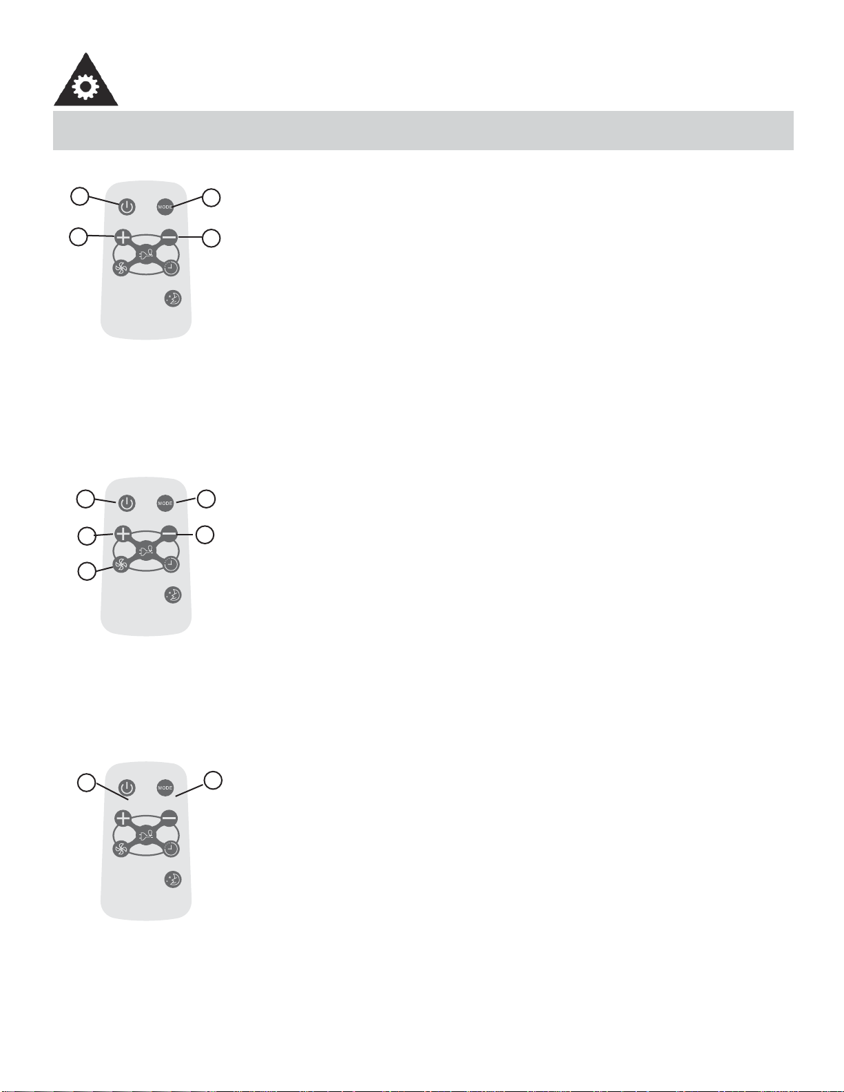
USING THE REMOTE CONTROLLER BUTTONS
Model / Modèle :
R15B
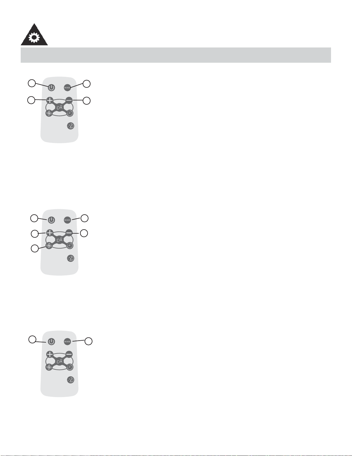
AUTO OPERATION
Ensure the unit is plugged in and power is available.
1. Press the ON/OFF button to start the air conditioner.
2. Press the mode button and select AUTO.
3. Press the TEMP + / - button to set the desired temperature. The temperature can be set
within a range of 17°C (62°F) to 30°C (86°F) in 1°C (1°F) increments.
NOTE:
1. In the auto mode, the air conditioner can logically choose the mode of Cool, Fan, Dehu-
midifying by sensing the difference between the actual ambient room temperature and
the set temperature on the remote controller.
2. In Auto mode, you cannot change the fan speed. It has already been automatically
controlled.
3. If the Auto mode is not comfortable for you, the desired mode can be selected manually.
-----------------------------------------------------------------------------------------------------------------------
Model / Modèle :
R15B
COOLING / FAN OPERATION
Ensure the unit is plugged in and power is available.
1. Press the ON/OFF button to start the air conditioner.
2. Press the MODE button to select Cool mode.
3. Press the TEMP +/- button to set the desired temperature. The temperature can be set
within a range of 17°C (62°F) to 30°C (86°F) in 1°C (1°F) increments.
4. Press the FAN button to select the fan speed in four-steps, LOW, MED, HIGH or AUTO.
NOTE:
In the FAN mode, the setting temperature is not displayed in the remote controller and you
are not able to control the room temperature either. In this case, only step 1, 2 and 4 may be
performed.
-----------------------------------------------------------------------------------------------------------------------
Model / Modèle :
R15B
DEHUMIDIFYING OPERATION
Ensure the unit is plugged in and power is available.
1. Press the ON/OFF button to start the air conditioner.
2. Press the MODE button to select Dehumidifying mode.
NOTE:
In the Dehumidifying mode, you cannot change the fan speed. It has already been automat-
ically controlled.
-----------------------------------------------------------------------------------------------------------------------
1
3
2
3
4
3
3
21
2
1
8

OPERATING INSTRUCTIONS
USING THE REMOTE CONTROLLER BUTTONS
Model / Modèle :
R15B
SLEEP OPERATION
• In this mode, the selected temperature will increase (when in cooling mode) by 1°C (2°F)
one half-hour after sleep mode has been selected.
• The temperature will increase by another 1°C (2°F) after an additional half-hour.
• This new temperature will be maintained for 6 hours before returning to the originally
selected temperature. This ends the Sleep mode and the unit will continue to operate as
originally programmed.
• The Sleep mode program can be cancelled at any time during operation by pressing the
Sleep button again.
-----------------------------------------------------------------------------------------------------------------------
Model / Modèle :
R15B
TIMER OPERATION
Pressing the TIMER button can set the Auto-start and Auto-stop time of the unit.
NOTE:
• To set Auto-start time, the unit must be in the OFF position.
• To set Auto-stop time, the unit must be in the ON position.
To set the Auto-start time
1. Push the TIMER button when the unit is off; only the Auto-start feature can be set.
2. Keep pressing the TIMER button. Each time pressed, will increase the selected time
by 0.5 hour increments. When the selected time has added up to 10 hours, each time
pressed will increase the selected time by 1 hour increments, up to 24 hours.
3. The time can be set in the range of 0-24 hours.
4. After the desired time has been selected, wait for about 10 seconds, until the setting
temperature reappears in the display window of the air conditioner. This indicates that
the program has been set.
-----------------------------------------------------------------------------------------------------------------------
1
1
Model / Modèle :
R15B
TIMER OPERATION
To set the Auto-stop time
1. Push the TIMER button when the unit is operational; only the Auto-stop feature can be
set.
2. Keep pressing the TIMER button. Each time pressed will increase the selected time by 1
hour increments, up to 24 hours.
3. The time can be set in a range of 0-24 hours.
4. After the desired time has been selected, wait for about 10 seconds, until the setting
temperature reappears in the display window of the air conditioner. This indicates that
the program has been set.
NOTE:
To cancel the TIMER setting, push the TIMER button until “0 hours” is displayed on the LCD
window of the air conditioner.
-----------------------------------------------------------------------------------------------------------------------
1
9
OPERATING INSTRUCTIONS
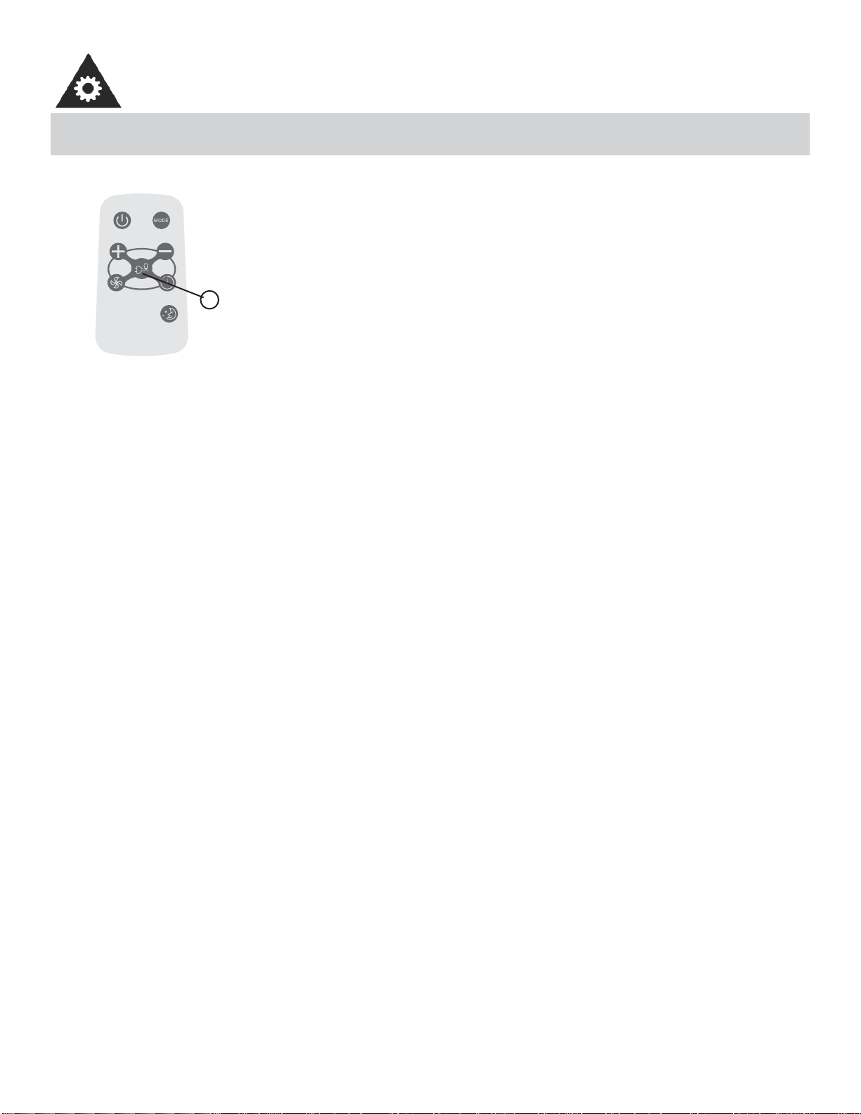
USING THE REMOTE CONTROLLER BUTTONS
Model / Modèle :
R15B
ENERGY SAVER OPERATION
This function is available in Cool, Dry, and Auto modes (only Auto-Cool and Auto-Fan
modes). The fan will continue to run for 3 minutes after the compressor has shut off. The
fan then cycles on for 2 minutes at 10 minute intervals, until the room temperature is
above the set temperature. At this point, the compressor turns back on and cooling starts.
-----------------------------------------------------------------------------------------------------------------------
1
• Protect the remote control from high temperatures, and keep it away from radiation exposure.
• Keep the control panel receiver out of direct sunlight.
• If the remote control will not be used for extended periods of time (vacations etc.), the battery should be removed.
• This Class B digital apparatus complies with the Canadian ICES-003 standard.
• The remote operates within a range of 8 meters (26 ft.) from the receiver located inside the main unit. Any obstruction
between the receiver and remote may cause signal interference, limiting the ability to program the main unit.
Note: This equipment has been tested and found to comply with the limits for a Class B digital device, pursuant to Part 15
of the FCC Rules. These limits are designed to provide reasonable protection against harmful interference in a residen-
tial installation. This equipment generates, uses and can radiate radio frequency energy and, if not installed and used in
accordance with the instructions, may cause harmful interference to radio communications. However, there is no guaran-
tee that interference will not occur in a particular installation. If this equipment does cause harmful interference to radio
or television reception, which can be determined by turning the equipment off and on, the user is encouraged to try to
correct the interference by one or more of the following measures:
1. Reorient or relocate the receiving antenna.
2. Increase the separation between the equipment and receiver.
3. Connect the equipment into an outlet on a circuit different from that to which the receiver is connected.
4. Consult the dealer or an experienced radio/TV technician for help. Changes or modifi cations not approved by the
party responsible for FCC compliance could void the user’s authority to operate the equipment.
This appliance complies with Part 15 of the FCC Rules. Operation is subject to the following two
conditions:
1. This device may not cause harmful interference.
2. This device must accept any interference received, including interference that may cause undesired operation.
10
OPERATING INSTRUCTIONS
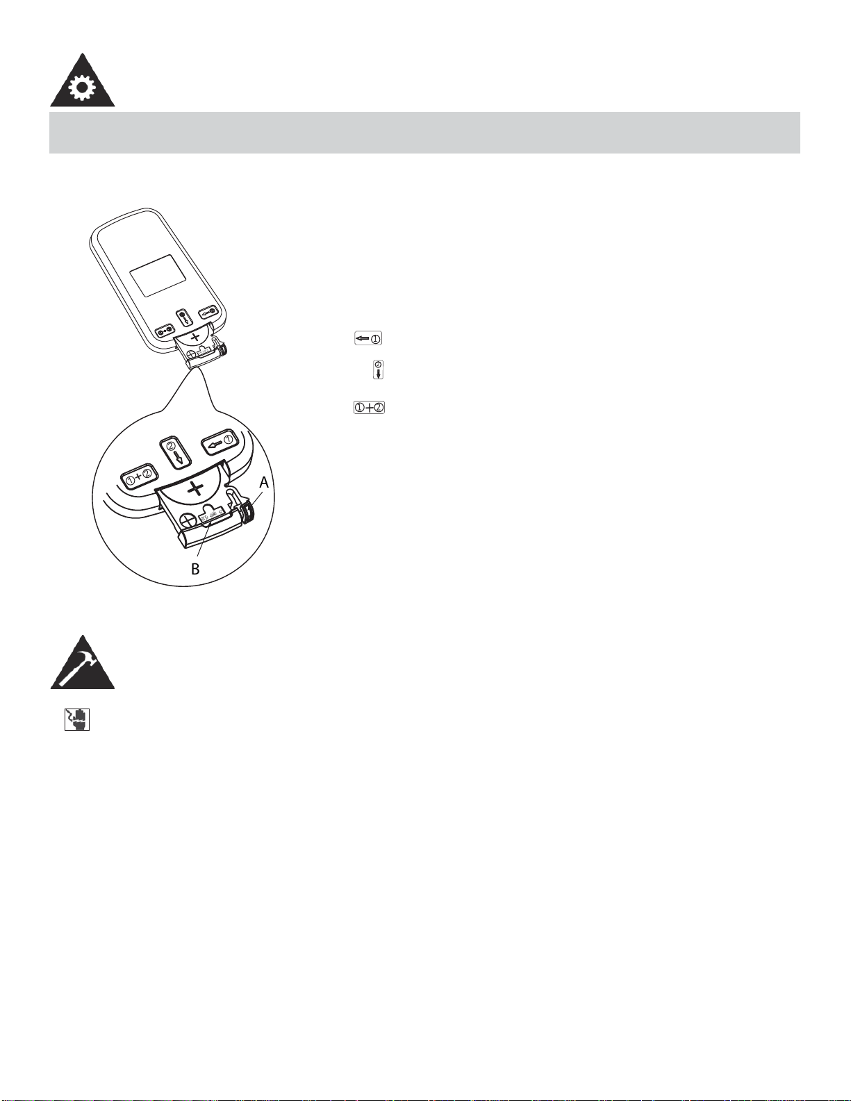
CHANGING THE BATTERY ON THE REMOTE
õ
Ðä
à
ä
ç
õÐ äà
ä
ç
1
2
1
2
+
B
A
1
2
1
2
+
The remote controller is powered by one button cell housed in the
rear part and protected by a cover. Remove the button cell accord-
ing to the arrow marked at the back of the remote controller.
1. Slightly press “A” position according to the number 1 arrow
direction by your forefi nger.
2. Press “B” position and pull it according to the number 2 arrow
direction by your thumb.
3. The above step 1 and 2 should be done simultaneously to
slide the button cell out.
INSTALLATION INSTRUCTIONS
TOOLS NEEDED FOR INSTALLATION:
• Screwdrivers: Phillips and fl at head.
• Power Drill: 1/8in. (3.2mm) diameter drill bit
• Pencil
• Measuring Tape
• Scissors
• Carpenter’s Level
ELECTRIC SHOCK HAZARD
To avoid the possibility of personal injury, disconnect power to the unit before installing or servicing.
NOTE: Your Room Air Conditioner is designed for easy installation in a single or double-hung window.
This unit is NOT designed for vertical (slider type) windows and/or through-the-wall applications.
11
INSTALLATION INSTRUCTIONS
BEFORE INSTALLING
• Check window opening size against dimensions of your unit.
• Check condition of window; all wood parts of the window must be in good shape and able to fi rmly hold the needed
screws. If not, make repairs before installing unit.
• Check for anything that could block airfl ow; check area outside window for things such as shrubs, trees, or awnings.
Inside, be sure furniture, drapes or blinds will not stop proper air fl ow.
• Carefully unpack air conditioner. Remove all packing material, and check for all included installation hardware.
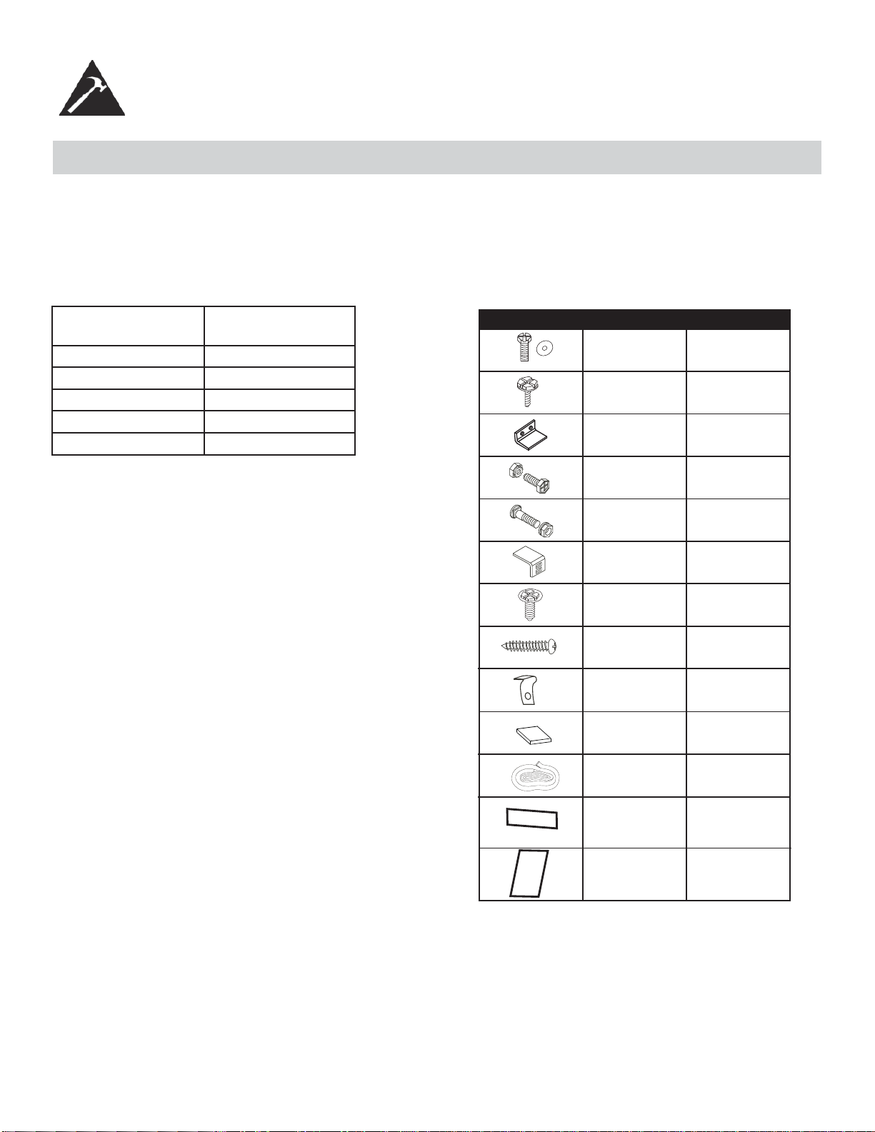
Model type: DAC150BBCWDB
DAC150BBUWDB
Unit height: 17.91
Unit width: 23.62
Min. window opening: 18 1/2”
Min. window width: 27 3/4”
Max. window width: 40 1/2”
7/16” locking screw
& flat washer for
window panels
1/2in.(13mm)
long Hex-head
screw
Safety Lock
1/2in.(12.7mm)
long screw and
locknut
3/4” long flat head
bolt and locknut
Sill Angle Bracket
5/16in. long Hex-head
locking screw for top
angle side retainer.
13/16in. (20mm)
screw
Frame lock
2 each
7
1
4 each
2 each
2
10
2
2
Fig. 1 INSTALLATION HARDWARE
Foam insert
2
Windowsash
seal foam
1
Weather-Stripping
5
Foam Insert
2
12
1. This room air conditioner is designed to fi t easily into a single or double hung window. However, since window designs
vary, it may be necessary to make some modifi cations for safe, proper installation.
2. Make sure window and frame are structurally sound and free from dry and rotted wood.
3. For maximum effi ciency, install the air conditioner on a side of the house or building which favours more shade than
sunlight. If the unit is in direct sunlight, it is advisable to provide an awning over the unit.
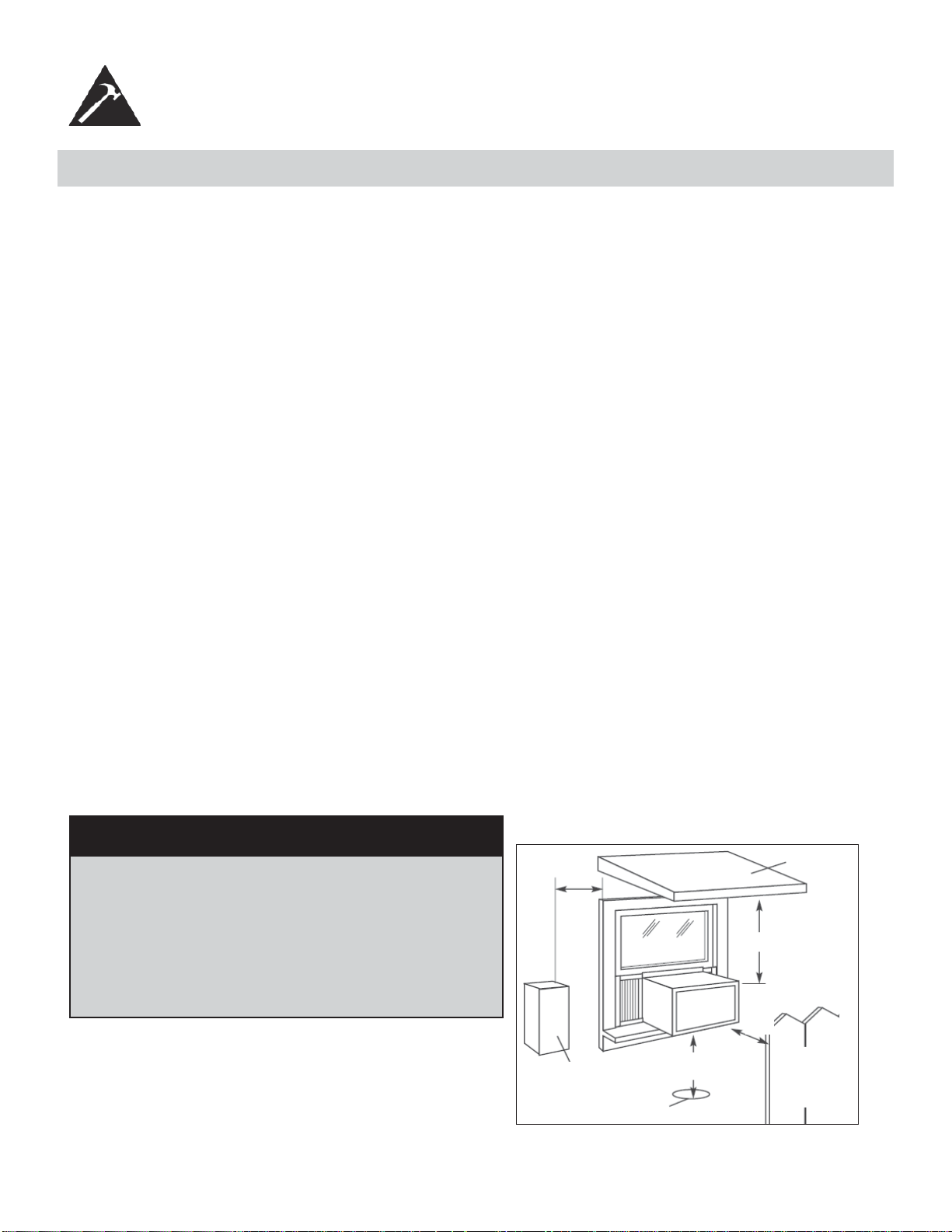
4. Provide suffi cient clearance around the cabinet to allow for ample air circulation through the unit (See Fig. 2). The
rear of the unit should be outdoors. It should not be in a garage, or inside a building. Keep unit as far away as possi-
ble from obstacles/obstructions and at least 30 in. (76 cm) above the fl oor or ground. Curtains and other objects within
the room should be prevented from blocking the air fl ow.
5. Be certain that the proper electrical outlet is within reach of the installation. Use only a single outlet circuit rated at 15
amps. All wiring should be in accordance with local and national electrical codes.
6. DO NOT install unit where leakage of combustible gas is suspected. Your air conditioner may fail to operate in air
containing oils (including machine oils), sulfi de gas, near hot springs, etc.
NOTE: Your unit is designed to evaporate condensation under normal conditions. However, under extreme humidity con-
ditions, excess condensation may cause basepan to overfl ow to the outside. The unit should be installed where conden-
sation run-off cannot drip on pedestrians or neighbouring properties.
NOTE: It is normal for your unit to drip a small amount of water, especially on excessively humid days.
INSTALLATION INSTRUCTIONS
LOCATION
Awning
Fence,
wall, or
other
obstacle
Ground
Side
Obstruction
20 in.
(50.8 cm)
Min
30 in. (76.2 cm)
Min
Min
12 in. (30.5 cm) Min
20 in.
(50.8 cm)
Fig. 2
NOTE: Save the shipping carton and packing materials for future storage or transportation. From the carton, remove the
plastic bag containing the installation hardware kit necessary for the installation of your air conditioner. Please check the
contents of the hardware kit against the corresponding model check list, prior to installation.
NOTE: Your Room Air Condtioner is designed for easy installation in a single or double-hung window. This unit is NOT
designed for vertical (slider type) windows and/or through-the-wall applications.
CAUTION
Because the compressor is located on the controls
side of the unit (left side), this side will be heavier and
more awkward to manipulate. Inadequate support on the
control side of the unit can cause injury and damage to
the appliance and other property. Therefore, it is recom-
mended that you have someone assist you during the
installation of this unit.
13
INSTALLATION INSTRUCTIONS
WINDOW MOUNTING
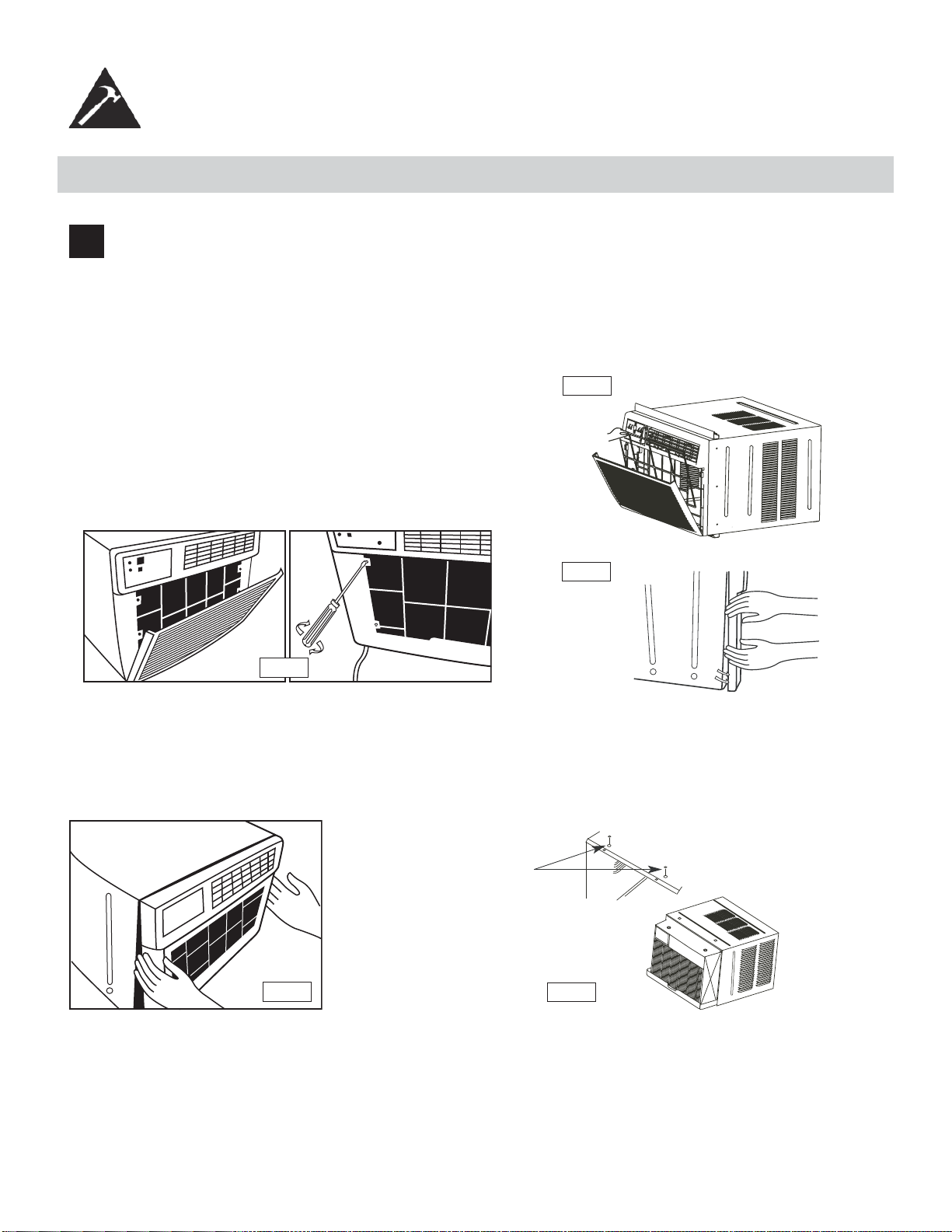
1
Remove Chassis:
1. Pull down front panel and remove fi lter (See Fig. A).
2. Lift front panel upwards and place to one side.
3. Locate the four (4) front screws and remove (Fig. B). These screws will be needed to re-install the front later.
4. Pry away the front panel from the cabinet sides as shown in Fig. C.
Fig. B
Fig. A
Fig. C
5. Gently lift front off unit and place to one side (See fi g. D)
6. Remove shipping screw from top of unit and also on the side by the base if installed.
7. Hold the cabinet while pulling on the base handle, and carefully remove the chassis from the cabinet.
8. Add two foam inserts to holes in top of cabinet where shipping screws were removed from (See fi g. E).
9. Your unit may come with internal packaging. This packaging must be removed prior to installing the air
conditioner back into the cabinet.
Fig. D
Fig. E
Foam inserts
14
INSTALLATION INSTRUCTIONS
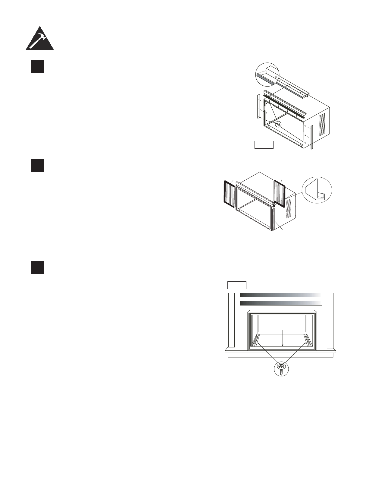
2
Install Top Angle and Side Bracket:
1. Attach foam gasket to top angle above holes as shown in Fig. F.
2. Install top angle and side retainers to cabinet as shown in Fig. F.
5/16in. (8mm)
long hex-head
Fig. F
3
Assemble Window Filler Panels (see Fig. G):
1. Place cabinet on fl oor, a bench, or table.
2. Slide the window fi ller panel frame into the top (L
shaped) and bottom (U shaped) channels. The shut-
ters are identifi ed (on the frame) as left and right.
3. Insert washer head locking screws (2) into holes in
top leg of fi ller panel frame. Do not totally tighten. Al-
low left to slide freely. Screws will be tightened later.
Plastic
Frame
“U”Shaped Channel
Window Filler Panel
“L” Shaped Mounting
Bracket
4
Install Top Angle and Side Bracket:
1. Open window and mark center of window sill.
2. Place cabinet in window with lower “U” channel of
cabinet fi rmly seated over window sill. Bring window
down temporarily behind top “L” bracket to hold
cabinet in place.
3. Shift cabinet left or right as needed to line up center
of cabinet on centre line marked on window sill.
4. Fasten cabinet to window sill with 2 screws (you
may want to pre-drill holes).
5. Add bottom rail seal over screws to window sill. See
Fig. H.
Fig. H
Bottom
Rail Seal
3/4in.(19mm) Long
Hex-head Screw
15
INSTALLATION INSTRUCTIONS
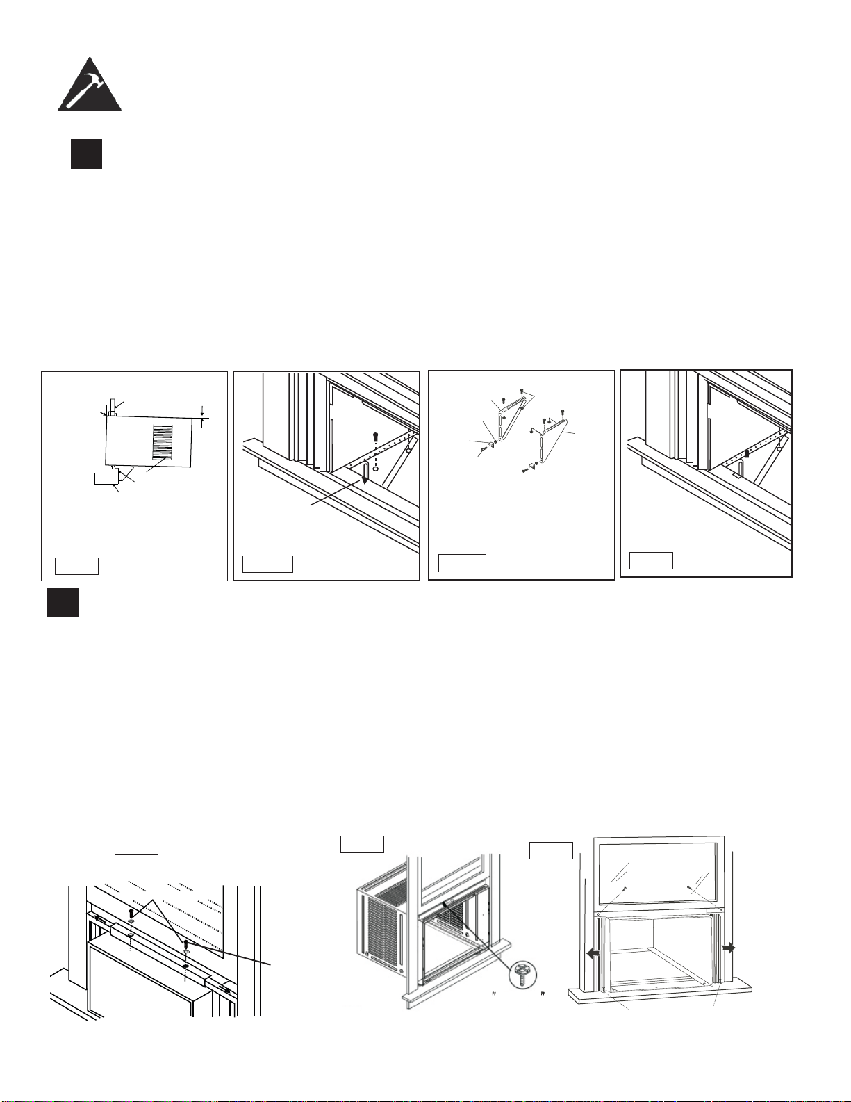
5
Install Support Bracket:
1. Hold each support bracket fl ush against outside of sill, and tighten to bottom of cabinet as shown. in Fig. J
¹.
Mark brackets at top level of sill, and remove.
2. Assemble sill anchor bracket to outside support legs at the market position, as seen in Fig. J
²
.
Hand tighten,
but allow for any changes later. NOTE: Check that air conditioner is tilted downwards to the outside, about
3 ° to 4°, as shown in Fig. I. After installation, condensed water should not drain from the overfl ow drain hole
during normal use. If you notice water leaking out, check the angle of tilt, and make any necessary adjust-
ments. However, on a very humid day, water leakage can occur- this is normal. Measure the tilt angle from
the cabinet’s edge . The distance H should be approximately 1 1/4” to 1 5/8”.
3. Install support brackets (with sill anchor brackets attached) to correct hole in bottom of cabinet as shown in
Fig. K.
4. Tighten all 6 bolts securely.
Mark
Fig. J1
Left
Locknut
Sill Anchor
Bracket
Flat Head
Bolt
2 Each Required For
Each Support Bracket
Right
1/2in.(12.7mm) Long
Left Screws And
Locknuts
Fig. J2
Fig. K
Window Sill
Window Sash
$ERXWóWRǫ
Sill Angle Bracket
Side Louvers
Fig. I
Measure
the tilt
angle from
the cabinet’s
edge.
H
6
Extend Window FIller Panels
1. Carefully raise the window to expose the fi ller panel locking screws. Loosen the screws do the fi ller panels slide
easily.
2. Extend panels to fi ll the widow completely. Using two 7/16 in (12mm) locking screws and a fl at washer to tighten
the locking screws on top (Fig. L1).
3. Close the window behind the top angle.
4. Attach the top angle to the window frame using a 3/32 drill bit to drill one hole through the hole in the middle of
the top angle into the window frame, and drive one ½ HEX-HEAD locking screw through the hole in the middle
of the top angle into the window frame, see Fig. L2.
5. Extend the window fi ller panels out against the window frame.
6. Use a 1/8” drill bit to drill a starter hole through the hole in the top leg of each window fi ller panel and into the
window sash (Fig. L3). Connect with one ½” long hex head screw.
7. Attach the frame lock to the window sill using one 13/16” (20mm) screw on each side as shown in Fig. L3.
16
Locking Screw
7/16"Locking
Screw
and Washer
Fig.L2
1/ 2 long
HEX-HEAD
SCREW
Fig.15B
1/2in. (13mm) long
Hex-head screw
13/16in. (20mm) Screw & Frame Lock (2)
Fig. L3
(2
)
1.
Fig.L1
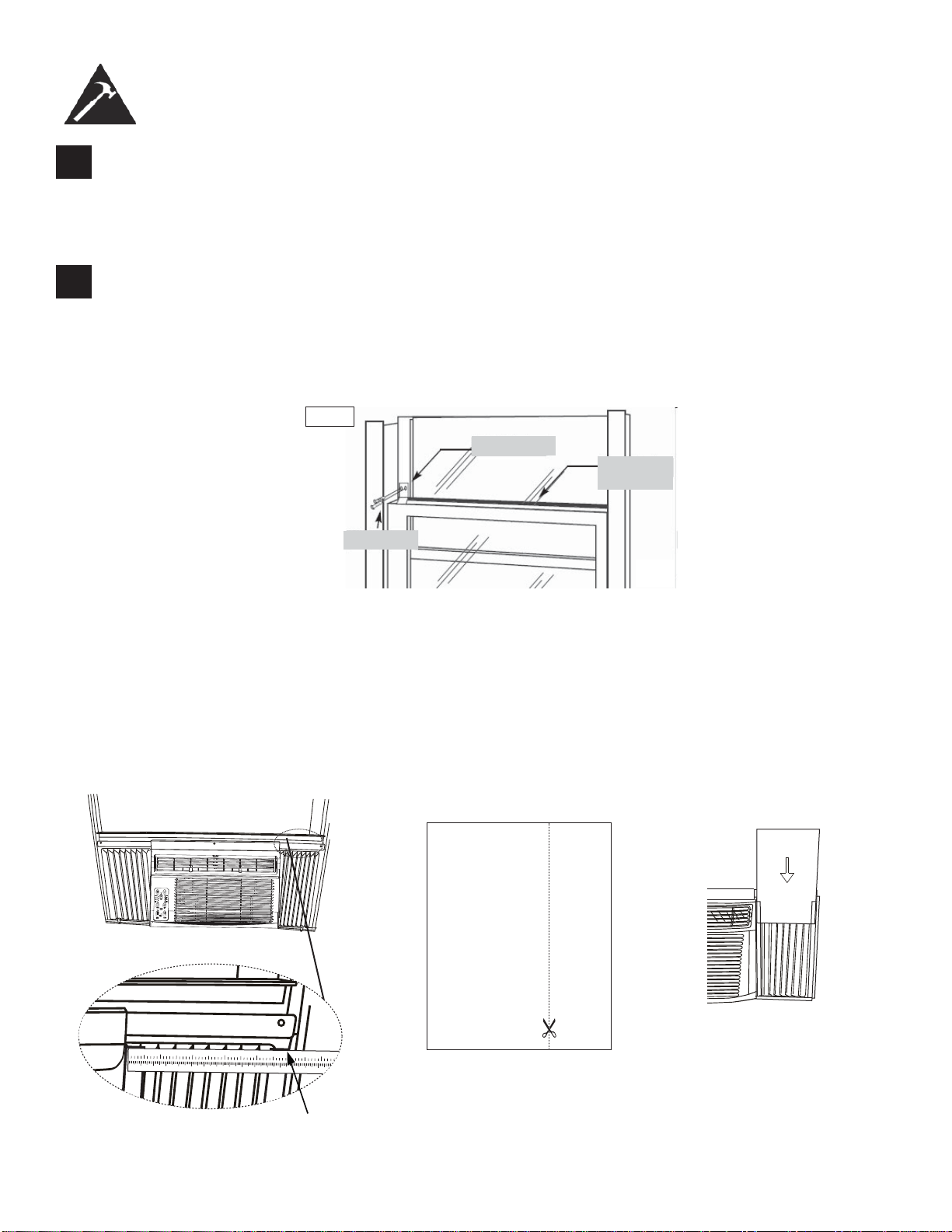
7
Install Window Lock and Sash Seal
1. Trim sash seal to fi t window width. Insert into space between upper and lower sashes (Fig. M).
2. Attach right angle safety lock as shown in Fig. M.
INSTALLATION INSTRUCTIONS
8
Install Chassis into Cabinet and Install:
1. Lift chassis and carefully slide into cabinet, leaving 6 inches protruding.
2. DO NOT push on controls or coils.
3. Be sure the chassis is fi rmly seated towards rear of cabinet.
4. Installation of front is the reverse of removal, outlined in section 1 (“Remove Chassis”)
Safety Lock
1/2” screw
Window
Sash Seal
Fig.M
17
Installing the Energy Effi cient Foam Insert
• After the unit is installed in the window, measure the width of the side curtain.
• If necessary, cut the foam insert down to the width of the side curtain.
• Slide the foam insert into the side curtain.
• Repeat for the other side. (See below)
NOTE: Apply the supplied weather-stripping where needed (cracks and spaces between the foam insert, window
kit and window frame).
12345678910 1
1121314151617
1
2
34
5
6
Step 1 Step 3Step 2
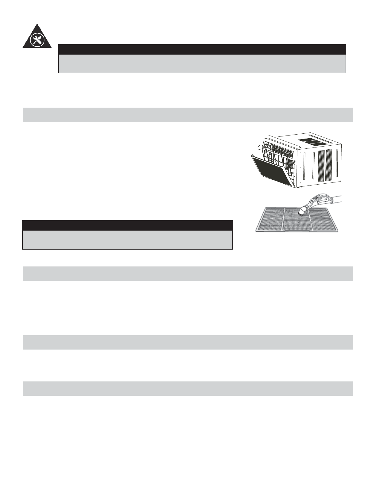
CLEANING THE CABINET
• Be sure to unplug the air conditioner to prevent shock or fi re hazard. The cabinet and front may be dusted with an
oil-free cloth or washed with a soft cloth dampened in a solution of warm water and mild liquid dishwashing detergent.
Rinse thoroughly and wipe dry.
• Be sure to wring excess water from the cloth before wiping around the controls. Excess water in or around the con-
trols may cause damage to the air conditioner.
WINTER STORAGE
If you plan to store the air conditioner during the winter, remove it carefully from the window according to the installation
instructions. Cover it with plastic or return it to the original carton. Always store the unit in the upright position.
DISPOSAL
Check for local regulatory compliance regarding the approved and safe disposal of this appliance.
18
CARE AND MAINTENANCE
CLEANING THE AIR FILTER
CAUTION
Before cleaning or servicing this unit, disconnect from any electrical supply outlets to prevent
possible shock or fi re hazard.
• DO NOT use gasoline, benzene, thinner, or any other chemicals to clean this unit, as these substances may cause
damage to the fi nish and deformation of plastic parts.
• Never use harsh cleaners, wax or polish on the cabinet front.
The air fi lter should be checked at least once a month to see if cleaning is
necessary. Trapped particles in the fi lter can build up and cause accumulation
of frost on the cooling coils.
• Push the vent handle to the vent closed position.
• Open the front panel.
• Grasp the fi lter, pull up and out.
• Wash the fi lter using liquid dishwashing detergent and warm water. Rinse
fi lter thoroughly.
• Gently shake excess water from the fi lter. Be sure the fi lter is thoroughly
dry before replacing.
• You may vacuum the fi lter to clean.
Note: Never use hot water over 40°C (104°F) to clean the air fi lter.
CAUTION
Never operate this unit without the air fi lter in place, as this may
result in damage to the unit.
Occasionally a problem may arise that is minor in nature, and a service call may not be neccessary. Use this troubleshoot-
ing guide for a possible solution. If the unit continues to operate improperly, call an authorized service depot or
Danby’s Toll Free Number 1-800-263-2629 for assistance.
TROUBLESHOOTING
PROBLEM POSSIBLE CAUSE SOLUTION
Unit does not work • Power is out
• The plug is not plugged in prop-
erly
• Plug current device tripped
• Control is off
• Wait for power to return
• Plug in properly
• Press the reset button after
resolving problem
• Turn control ON and set to de-
sired setting
Air from unit does not feel cold
enough
• Room temp. below 17°C (62°F)
• Temp. sensing element touching
cold coil (behind air fi lter)
• Temp. set too high
• Compressor shut off by changing
modes
• Will not cool until room temp.
rises above 17°C (62°F)
• Straighten tube away from coil
• Reset to a lower temp.
• Wait approx. 3 minutes and
listen for compressor to restart
when in cool mode
Air conditioner cooling but room
is too warm- ice forming on cool-
ing coil behind decorative front
• Outdoor temp. below 17°C
(62°F)
• Air fi lter may be dirty
• Thermostat too cold for night-
time cooling
• To defrost coil, set to FAN ONLY
• Clean fi lter as per instructions
• Set temp. to a higher setting
Air conditioner cooling but room
is too warm- NO ice forming on
cooling coil behind decorative
front
• Dirty air fi lter - air restricted
• Temp. is set too high
• Air directional louvers positioned
improperly
• Front of unit blocked (i.e. by
drapes), restricting air distribu-
tion
• Doors, windows, registers etc.
open, cold air escaping
• Unit recently turned on in hot
room
• Clean air fi lter
• Set to lower temp.
• Position louvers for better air
distribution
• Clear blockage in front of unit
• Close doors, windows, registers
• allow additonal time to remove
“stored heat” from room
Air conditioner turns on and off
rapidly
• Dirty air fi lter - air restricted
• Outside temp. extremely hot
• Clean air fi lter
• Set fan speed to higher setting
to bring air past cooling coils
more frequently
Noise when unit is cooling • Air movement sound
• Window vibration
• This is normal. If too loud, set to
slower fan setting
• Poor installation-refer to instal-
lation instructions or check with
installer
Water dripping INSIDE when unit
is cooling
• Improper installation • Tilt air conditioner silghtly to the
outside to allow water drainage
Water dripping OUTSIDE when
unit is cooling
• Unit removing large quantity of
moisture from humid room
• This is normal during excessive-
ly humid days
Remote sensing deactivating
prematurely
• Remote control not located with-
in range
• Remote control signal obstructed
• Place remote control withing 8
meters (20 Ft.) and 180° radius
of front of the unit
• Remove obstruction
Room too cold • Set temperature too low • Increase set temperature
19

LIMITED IN-HOME APPLIANCE WARRANTY
This quality product is warranted to be free from manufacturer’s defects in material and workmanship, provided that the unit is used under the normal operating
conditions intended by the manufacturer.
This warranty is available only to the person to whom the unit was originally sold by Danby Products Limited (Canada) or Danby Products Inc. (U.S.A.) (hereafter
“Danby”) or by an authorized distributor of Danby, and is non-transferable.
TERMS OF WARRANTY
Plastic parts, are warranted for thirty (30) days only from purchase date, with no extensions provided.
First Year
During the rst twelve (12) months, any functional parts of this product found to be defective, will be repaired or replaced, at warrantor’s
option, at no charge to the ORIGINAL purchaser.
To obtain
Danby reserves the right to limit the boundaries of “In Home Service” to the proximity of an Authorized Service Depot. Any app liance
Service
requiring service outside the limited boundaries of “In Home Service” , it will be the consumer’s responsibility to transport the appliance (at
their own expense) to the original retailer (point of purchase) or a service depot for repair. See “Boundaries of In Home Serv ice” below.
Contact your dealer from whom your unit was purchased, or contact your nearest authorized Danby service depot, where service
must be performed by a qualied service technician.
If service is performed on the units by anyone other than an authorized service depot, or the unit is used for commercial appli cation, all
obligations of Danby under this warranty shall be void.
Boundaries of
If the appliance is installed in a location that is 100 kilometers (62 miles) or more from the nearest service center your unit must be
In Home Service
delivered to the nearest authorized Danby Service Depot, as service must only be performed by a technician qualied and certif ied for
warranty service by Danby. Transportation charges to and from the service location are not protected by this warranty and are t he
responsibility of the purchaser.
Nothing within this warranty shall imply that Danby will be responsible or liable for any spoilage or damage to food or other c ontents of this appliance, whether due
to any defect of the appliance, or its use, whether proper or improper.
EXCLUSIONS
Save as herein provided, Danby, there are no other warranties, conditions, representations or guarantees, express or implied, m ade or intended by Danby or its
authorized distributors and all other warranties, conditions, representations or guarantees, including any warranties, conditio ns, representations or guarantees
under any Sale of Goods Act or like legislation or statue is hereby expressly excluded. Save as herein provided, Danby shall no t be responsible for any damages
to persons or property, including the unit itself, howsoever caused or any consequential damages arising from the malfunction o f the unit and by the purchase of
the unit, the purchaser does hereby agree to indemnify and hold harmless Danby from any claim for damages to persons or propert y caused by the unit.
GENERAL PROVISIONS
No warranty or insurance herein contained or set out shall apply when damage or repair is caused by any of the following:
1) Power failure.
2) Damage in transit or when moving the appliance.
3) Improper power supply such as low voltage, defective house wiring or inadequate fuses.
4) Accident, alteration, abuse or misuse of the appliance such as inadequate air circulation in the room or abnormal operating con ditions
(extremely high or low room temperature).
5) Use for commercial or industrial purposes (ie. If the appliance is not installed in a domestic residence).
6) Fire, water damage, theft, war, riot, hostility, acts of God such as hurricanes, oods etc.
7) Service calls resulting in customer education.
8) Improper Installation (ie. Building-in of a free standing appliance or using an appliance outdoors that is not approved for out door application).
Proof of purchase date will be required for warranty claims; so, please retain bills of sale. In the event warranty service is required, present this document to our
AUTHORIZED SERVICE DEPOT.
Danby Products Limited
PO Box 1778, Guelph, Ontario, Canada N1H 6Z9
Telephone: (519) 837-0920 FAX: (519) 837-0449
Danby Products Inc.
PO Box 669, Findlay, Ohio, U.S.A. 45840
Telephone: (419) 425-8627 FAX: (419) 425-8629
04/09
1-800-263-2629
Warranty Service
In-home
If the appliance is installed in a location that is 100 kilometres (62 miles) or more from the nearest
service centre your unit must be delivered to the nearest authorized Danby Service Depot, as service
must only be performed by a technician qualified and certified for warranty service by Danby. Transpor-
tation charges to and from the service location are not protected by this warranty and are the responsi-
bility of the purchaser.
During the first twelve (12) months, any functional parts of this product found to be defective, will be
repaired or replaced, at warrantor’s option, at no charge to the ORIGINAL purchaser.
Danby reserves the right to limit the boundaries of “In Home Service” to the proximity of an Authorized
Service Depot. Any appliance requiring service outside the limited boundaries of “In Home Service” ,it
will be the consumer’s responsibility to transport the appliance (at their own expense) to the original
retailer (point of purchase) or a service depot for repair. See “Boundaries of In Home Service” below.
Contact your dealer from whom your unit was purchased, or contact your nearest authorized Danby
service depot, where service must be performed by a qualified service technician. If service is performed
on the units by anyone other than an authorized service depot, or the unit is used for commercial
application, all obligations of Danby under this warranty shall be void.
First year
To obtain
service
Boundaries of
in-home service
LIMITED IN-HOME APPLIANCE WARRANTY
This quality product is warranted to be free from manufacturer’s defects in material and workmanship, provided that the unit is
used under the normal operating conditions intended by the manufacturer.
This warranty is available only to the person to whom the unit was originally sold by Danby Products Limited (Canada) or
Danby Products Inc. (U.S.A.) (hereafter “Danby”) or by an authorized distributor of Danby, and is non-transferable.
TERMS OF WARRANTY
Plastic parts, are warranted for thirty (30) days only from purchase date, with no extensions provided.
Nothing within this warranty shall imply that Danby will be responsible or liable for any spoilage or damage to food or other
contents of this appliance, whether due to any defect of the appliance, or its use, whether proper or improper.
EXCLUSIONS
Save as herein provided, by Danby, there are no other warranties, conditions, representations or guarantees, express or
implied, made or intended by Danby or its authorized distributors and all other warranties, conditions, representations or
guarantees, including any warranties, conditions, representations or guarantees under any Sale of Goods Act or like legislation
or statute is hereby expressly excluded. Save as herein provided, Danby shall not be responsible for any damages to persons
or property, including the unit itself, howsoever caused or any consequential damages arising from the malfunction of the unit
and by the purchase of the unit, the purchaser does hereby agree to indemnify and hold harmless Danby from any claim for
damages to persons or property caused by the unit.
GENERAL PROVISIONS
No warranty or insurance herein contained or set out shall apply when damage or repair is caused by any of the following:
1) Power failure.
2) Damage in transit or when moving the appliance.
3) Improper power supply such as low voltage, defective house wiring or inadequate fuses.
4) Accident, alteration, abuse or misuse of the appliance such as inadequate air circulation in the room or abnormal operating
conditions (extremely high or low room temperature).
5) Use for commercial or industrial purposes (i.e., If the appliance is not installed in a domestic residence).
6) Fire, water damage, theft, war, riot, hostility, acts of God such as hurricanes, floods etc.
7) Service calls resulting in customer education.
8) Improper Installation (i.e., building-in of a free standing appliance or using an appliance outdoors that is not approved for
outdoor application). Proof of purchase date will be required for warranty claims; so, please retain bills of sale. In the event
warranty service is required, present this document to our AUTHORIZED SERVICE DEPOT.
Warranty Service
In-home
Danby Products Limited
PO Box 1778, Guelph, Ontario, Canada N1H 6Z9
Telephone: (519) 837-0920 FAX: (519) 837-0449
Danby Products Inc.
PO Box 669, Findlay, Ohio, U.S.A. 45840
Telephone: (419) 425-8627 FAX: (419) 425-8629
1-800-263-2629
07/14
BIENVENUE
Bienvenue dans la famille Danby. Nous sommes fi ers de la qualité de nos produits et nous croyons fermement au service
par une assistance fi able. Vous le découvrirez à la lecture de ce guide facile d’utilisation et vous en aurez la confi rmation
par notre service d’assistance à la clientèle. Mais ce qui est encore mieux, vous pourrez bénéfi cier de ces avantages à
chaque utilisation de votre appareil. Ceci est important parce que votre nouvel appareil fera partie de votre famille pour
longtemps.
À titre de référence, vous pouvez agrafer à cette page une copie de votre fi che d’achat de l’appareil. Inscrivez les rensei-
gnements suivants fournis (sur la plaque signalétique du fabricant sur le côté droit de l’appareil au-dessus du cordon
d’alimentation).
Veuillez noter les informations ci-dessous; ces renseignements seront nécessaires si votre appareil a besoin
d’entretien ou pour les demandes de renseignements généraux. Pour bénéfi cier d’une opération de maintenance
ou de dépannage, le reçu original sera exigé.
REMARQUE : CET APPAREIL N’A PAS ÉTÉ CONÇU POUR UNE INSTALLATION À TRAVERS UNE PAROI MURALE.
Numéro de modèle :
Numéro de série :
Date d’achat :
BESOIN D’ASSISTANCE ?
Veuillez trouver quelques conseils avant de faire appel à nos
services, cela nous aidera à mieux vous servir :
Lisez ce guide :
Il comprend des instructions pour l’utilisation et l’entretien
adapté de votre appareil.
Si votre nouvel appareil est endommagé :
Contactez immédiatement le revendeur (ou le fabricant).
Gagnez du temps et de l’argent :
Avant de faire appel à nos services, consultez à nouveau
la section « Dépannage ». Cette section vous aidera à
résoudre des problèmes courants.
Si une réparation est nécessaire, ne vous inquiétez pas, la
solution est au bout du fi l.
AVERTISSEMENT :
Une fi che de mise à la terre mal branchée peut entraîner un risque d’incendie, de
choc électrique ou de blessures aux personnes qui utilisent l’appareil. Si vous
n’êtes pas certain que l’appareil est correctement mis à la terre, consultez un
préposé du service qualifi é.
21
1-800-26-
(1-800-263-2629)
1. Tous les câblages doivent être conformes aux codes électriques locaux et nationaux et doivent être installés par un
électricien qualifi é. Si vous avez la moindre question au suject des instructions ci-dessous, contactez un électricien
qualifi é.
2. Vérifi ez la fourniture d’alimentation électrique disponible et résolvez tout problème de câblage AVANT d’installer et de
faire fonctionner cet appareil.
3. Ce climatiseur à 115V ou 230/208V utilise 11,5 ampères ou moins de puissance nominale et peut être utilisé dans
toute prise de courant domestique de but général adéquatement câblée. Voir le Tableau 1 pour les spécifi cations pour
le circuit de dérivation individuel.
4. Pour votre sécurité et votre protection, cet appareil est mis à la terre par la fi che du cordon d’alimentation lorsqu’elle
est branchée dans une prise murale qui lui correspond. Si vous n’êtes pas certain que votre prise de courant murale
est mise à la terre adéquatement, veuillez consulter un électricien qualifi é.
5. La prise murale doit correspondre à la fi che à 3 broches sur le cordon de service fourni avec l’appareil. N’utilisez PAS
de fi ches d’adaptation. Voir le Tableau 2 pour les renseignements sur les prises de courant et les fusibles.
6. La plaque signalétique sur l’appareil contient des données électriques et techniques; elle se trouve sur le côté droit
de l’appareil, au-dessus du cordon d’alimentation.
TABLEAU 1
Circuit de distribution individuel suggéré
Ampères de plaque d’intifi cation Calibre de fi l AWG*
11,5 14
AWG- American Wire Guage (Calibre de fi l américain)
*Basé sur le fi l en cuivre à une température nominale
de 105°C (221°F)
TABLEAU 2
Types de fusibles et de réceptacles
Modèle DAC150BBCWDB / DAC150BBUWDB
Tension nominale 125 240
Ampères 15 15
Prise de courant
Intensité de fusible 15 15
20
Fusible temporisé Type fi che
(ou disjoncteur de circuit)
Consignes de sécurité importantes
LISEZ TOUTE L’INFORMATION DE SÉCURITÉ AVANT UTILISATION
POUR VOTRE SÉCURITÉ : Lire attentivement ces instructions avant d’utiliser l’appareil.
SPÉCIFICATIONS ÉLECTRIQUES
Ne jamais couper, enlever,
ou modifier la broche
de masse.
22
Le cordon d’alimentation fourni avec cet air conditionné contient un dispositif qui détecte les dommages au cordon. Pour
tester si votre cordon d’alimentation fonctionne adéquatement, vous devez faire ce qui suit :
1. Branchez le cordon d’alimentation à prise d’alimentation électrique.
2. Le cordon d’alimentation possède deux boutons situés sur la tête de la fi che. L’un des boutons est identifi é par
« TEST » et l’autre bouton par « RESET ». Appuyez sur le bouton « TEST » et vous entendrez un déclic puisque le
bouton « RESET » sera ressorti.
3. Appuyez sur le bouton « RESET » et vous entendrez un déclic lorsque le bouton sera enfoncé.
4. Le cordon d’alimentation est maintenant alimenté et il fournit de l’électricité à l’air conditionné. (Sur certains produits,
ceci sera aussi indiqué par une lumière sur la tête de la fi che).
REMARQUE : Le cordon d’alimentation fourni avec ce climatiseur contient un dispositif de détection de duite de courant
conçu pour réduire les risques d’incendie. Advenant le cas que le cordon d’alimentation soit endommagé, il ne peut être
réparé et doit être remplacé avec un nouveau cordon provenant du fabricant.
• Ce dispositif ne devrait être utilisé sous sucune circonstance pour mettre en marche ou arrêter l’unité.
• Le bouton de « RESET » doit toujours être enfoncé pour un fonctionnement normal.
• Le cordon d’alimentation doit être remplacé s’il ne se réinitialise pas lorsque le bouton « TEST » est enfoncé.
REMARQUE : Sur certaines fi ches, les boutons se trouvent
en haut.
CONTRÔLE DE L’APPAREIL
Consignes de sécurité importantes
LISEZ TOUTE L’INFORMATION DE SÉCURITÉ AVANT UTILISATION
POUR VOTRE SÉCURITÉ : Lire attentivement ces instructions avant d’utiliser l’appareil.
L’ÉCONOMIE DE L’ÉNERGIE
Votre appareil ménager est conçu pour l’effi cacité en économie de l’énergie. Pour le rendement maximal, observer
les recommandations qui suivent.
1. Choisir un réglage du thermostat qui répond à vos besions de confort et laisser au réglage choisi.
2. Le fi ltre à air est très effi cace pour éliminer les particules qui fl ottent dans l’air. Conserver le fi ltre à air propre en tout
temps. (Habituellement, il faut nettoyer tous les 2 semaines. Cela peut varier selon la qualité d’air.)
3. Utiliser des draperies, des rideaux ou des stores pour prévenir la pénétration et le réchauffement de la pièce par les
rayons directs du soleil, mais ne pas permettre la restriction de la circulation d’air autour de l’unité par les draperies
ou les rideaux.
4. Activer votre climatiseur avant que la température de l’air extérieur ne soit très chaude et inconfortable. Ceci prévi-
endra une période initiale d’inconfort avant que l’unité ne puisse refroidir la pièce. L’usage de la caractéristique de
MINUTERIE programmable d’arrêt et de mise en marche automatique représente un important avantage à cet effet si
elle est utilisée à pleine capacité.
5. Quand températures externes sont suffi samment froides, placer le climatiseur hors de service et utiliser le MODE DE
VENTILATEUR à la position HAUTE, MOYENNE ou BASSE. Ceci fait circuler l’air à l’intérieur de la pièce pour fournir
un certain confot de climatisation en utilisant moins d’électricité.
Branchez et
pressez la
remise
TEST
RESET
23
CARACTÉRISTIQUES
CONTRÔLE DE L’APPAREIL
1. Bouton MARCHE/ARRÊT (ON/OFF) : Appuyez sur ce bouton pour allumer l’appareil ou l’éteindre. REMARQUE :
L’appareil initiera la fonction d’Économiseur d’Énergie automatiquement, lorsque l’appareil est en modes Frais (Cool),
Sec (Dry), et Auto.
2. Boutons PLUS/MOINS (UP/DOWN) pour la température : Pour régler la température, appuyez sur le bouton PLUS
( ) ou MOINS ( ) ou maintenez-le enfoncé jusqu’à ce que la température voulue soit affi chée. Cette tempéra-
ture sera maintenue automatiquement entre 17°C (62°F) and 30 °C (86°F). En mode Frais, la température réglée est
affi chée. En mode Ventilateur la température ambiante actuelle est affi chée.
3. Bouton Vitesse du ventilateur (Fan Speed) : Choississez entre quatre réglages de ventilateur différents : Auto, Bas,
Moyen et Haut. La vitesse du ventilateur change chaque fois que vous appuyez sur le bouton.
4. Bouton Mode : Vous permet de choisir le mode d’opération désiré : Auto, Frais (Cool), Sec (Dry), Ventilateur (Fan).
Le mode choisi sera dénoté par l’affi cheur au-dessus du bouton.
Pour fonctionner en mode automatique :
• Le mode Auto est un programme préréglé qui choisit automatiquement le mode de fonctionnement et la vitesse du
ventilateur, selon le réglage de la température. Un exemple de l’opération en mode Auto suit.
• Si vous voudriez réfroidir la pièce, votre température désirée/réglée sera plus basse que la température ambiante, et
le climatiseur initiera le mode de refroidissement (cool). Une fois que la température desirée de la pièce est atteinte,
le climatiseur passera au mode Ventilateur (Fan), pour faire circuler l’air refroidi dans la pièce. Quand la température
de la pièce augmente, l’appareil passera encore une fois dans le mode de refroidissement, et le cycle du mode Auto
recommencera.
Pour fonctionner en mode sec (dry) :
• Dans ce mode, il n’est pas possible de régler le niveau d’humidité desiré; il est préréglé automatiquement. Le réglage
par défaut de ventilateur dans le mode Sec et « bas ». Puisque le compresseur est en train de fonctionner pour en-
lever l’humidité de l’air, vous observez un degré de refroidissement, comme effet secondaire.
Pour fonctionner en mode Ventilateur seulement :
• Utilisez cette fonction lorsque vous n’avez pas besoin de la fonction de refroidissement, par exemple pour faire circu-
ler l’air dans la pièce ou pour évacuer l’air vicié. N’oubliez pas d’ouvrir l’évent pendant cette fonction, mais gardez-le
fermé pendant le refroidissement pour obtenir une effi cacité maximale. Dans ce mode, vous pouvez choisir la vitesse
du ventilateur que vous préférez. Dans le mode ventilateur, la température ne peut pas être réglée, donc l’appareil
affi chera la température ambiante.
5. Économiseur d’énergie (Energy Saver) : Cela est le réglage par défaut de ce modèle. L’appareil ajuste le ventila-
teur automatiquement (en marche et en arrêt) quand le compresseur n’est pas en service. Le ventilateur continuera
à fonctionner pendant 3 minutes après que le compresseur s’est étendu. Après cela, le ventilateur se met en marche
pendant 2 minutes, avec des intervalles de 10 minutes jusqu’à ce que la température ambiante de la chambre est
plus élevée que la température choisie/réglée. À ce point-là, le compresseur se remet en marche et le refroidissement
recommence. Lorsque l’appareil est en mode Economiseur d’énergie, l’affi cheur au-dessus du bouton d’Économiseur
d’énergie s’allumera. Pour sortir l’appareil du mode Économiseur d’énergie- l’affi cheur au-dessus du bouton s’éteign-
era. Si vous choissez de faire fonctionner l’appareil sans l’option d’Économiseur d’énergie, le ventilateur fonctionnera
continuellement, lorsque le compresseur n’est pas en service.
Panneau du
Commande
Entrée d’air
intérieur
Caisson
24
CONTRÔLE DE L’APPAREIL (suite)
6. Bouton sommeil (Sleep) : Appuyez sur ce bouton pour initier le mode Sommeil. Dans ce mode,
la température sélectionnée augmente (en mode refroidissement) de 1°C (2°F) une demi-heure après la sélection
du mode. La température augmentera ensuite de 1°C (2°F) supplémentaires au bout d’une autre demi-heure. Cette
nouvelle température sera maintenue pendant 6 heures avant le retour à la température initialement sélectionnée.
Cela met fi n au mode Sommeil et l’appareil continuera de fonctionner conformément à sa programmation initiale. Le
programme du mode Sommeil peut être annulé à tout moment pendant son fonctionnement en appuyant à nouveau
sur le bouton Sommeil.
7. Bouton Minuteur (Timer) (Marche/Arrêt automatique) : Lorsque vous appuyez sur le bouton Minuteur (Timer),
le voyant lumineux à côté du mot « ON » s’allume; cela induique que le programme de mise en marche
automatique est amorcé. Appuyez sur les boutons PLUS ( ) ou MOINS ( ) ou maintenez-les enfoncés pour
modifi er l’heure automatique par intervalles de 0,5 heures jusqu’à 10 heures, puis par intervalles de 1 heure jusqu’à
24 heures. La commande effectue un compte à rebours jusqu’à l’heure du début. L’heure sélectionnée apparaît en 5
secondes et le système retourne automatiquement à l’affi chage du réglage de température précédent. Le fait
d’ALLUMER ou d’ÉTEINDRE l’appareil à n’importe quel moment annule la fonction de marche/arrêt automatique.
8. Bouton Vérifi cation du fi ltre (Check Filter) : Cette fonction vous rappelle de nettoyer le fi ltre à air pour assurer un
fonctionnement plus effi cace. Le voyant DEL s’allume au bout de 250 heures de fonctionnement. Pour réinitialiser
la fonction après le nettoyage du fi ltre, appuyez à nouveau sur le bouton Vérifi cation du fi ltre (Check Filter) et le
voyant s’éteindra.
FONCTIONS SUPPLÉMENTAIRES :
• Le circuit de refroidissement a un départ différé automatique de 3 minutes si l’appareil est éteint et rallumé rapide-
ment. Cela empêche la surchauffe du compresseur et un déclenchement possible du coupecircuit. Le ventilateur
continue de fonctionner pendant cette période.
• La commande maintient la température réglée à 2° près entre 17°C et 30°C (62°F à 86°F)
• La commande peut affi cher la température en degrés Celsius (°C) ou en degrés Fahrenheit (°F). Pour passer d’une
échelle à l’autre, appuyez sur les boutons Plus ou Moins de la température et du minuteur (Up and Down Temp./Tim-
er) au même moment et maintenez-les enfoncés pendant 3 secondes.
CARACTÉRISTIQUES
25
RÉGLAGE DU DÉBUT D’AIR
Le louvres orientables dans 4 directions vous permettent d’envoyer l’air vers le haut, le bas, la gauche ou la droite dans la
pièce, au besoin.
RECOMMANDATION : Pendant le refroidissement, orientez les pales vers le haut. Si vous orientez les pales vers le bas
et si l’appareil fonctionne en mode Refroidissement pendant une période prolongée, il est possible que se forme de la
condensation qui coulera de la surface des pales.
Vers le haut ou le bas
Gouche ou droit
UTILISATION DE LA TÉLÉCOMMANDE
ä
â
i
ä
Å
Å
à
ä
~
Ä
è
Ä
à
ã
ê
ã
è
Ä
à
ã
~
ä
í
â
é
í
Ñ
â
Ç
Å
{
â
è
Ñ
à
Ä
ç
é
á
Ä
Ä
ã
8m
Emplacement de la télécommande
• Utilisez la télécommande à une distance maximale de 8 mètres de l’appareil, en
l’orientant dans la direction du récepteur. La réception est confi rmée par un bip
sonore.
CARACTÉRISTIQUES
MISE EN GARDE
• Le climatiseur ne fonctionne pas si le signal envoyé par la
télécommande à l’unité intérieure est bloqué par des rideaux, des
portes ou d’autres matériaux.
• Ne laissez pas de liquides tomber sur la télécommande. N’expo-
sez pas la télécommande à la chaleur ou à la lumière directe du
soleil.
• Si le récepteur du signal infrarouge, qui se trouve sur l’unité
intérieure est exposé à la lumière directe du soleil, il est possible
que le climatiseur ne fonctionne pas correctement. Tirez les ride-
aux pour empêcher que la lumière ne tombe sur le récepteur.
• Si d’autres appareils électriques réagissent à la télécommande,
déplacez-les ou communiquez avec l’atelier de réparation.
CONSIGNES D’UTILISATION
26
CONSIGNES D’UTILISATION
Modèle R15B
Tension nominale 3V (pile bouton : CR2025)
Tension la moins élevée du
CPU émetteur de signal
2V
Portée de réception du signal 8 m
Environnement De -8°C à 60°C (18°F à 140°F)
CARACTÉRISTIQUES DE LA TÉLÉCOMMANDE
Model / Modèle :
R15B
BOUTON MARCHE/ARRÊT
Appuyez sur ce bouton pour mettre
en marche le climatiseur. Appuyer
encore une fois pour arrêter l’appar-
eil. REMARQUE : L’appareil initiera
la fonction d’Économiseur d’Énergie
automatiquement, lorsque l’appareil
est en modes Frais, Sec, Auto (Au-
to-Frais et Auto Ventilateur modes
seulement).
BOUTON AUGMENTER LA
TEMPÉRATURE
Appuyez sur ce bouton pour aug-
menter le réglage de la tempéra-
ture par intervalles de 1°C (1°F)
jusqu’à 30°C (86°F).
BOUTON VENTILATEUR
Utilisé pour sélectionner la vitesse du
ventilateur en quatre étapes :
BASSE MOY ÉLEVÉE AUTO
BOUTON ÉCONOMISEUR D’ÉNER-
GIE
Appuyez sur ce bouton pour activer
le mode Économiseur d’énergie.
Appuyez-le encore une fois pour
désactiver la fonction. Cette fonction
est disponible lorsque l’appareil est en
modes Frais, Sec, et Auto (Auto-Frais
et Auto-Ventilateur modes seulement).
BOUTON MODE
Chaque fois que vous appuy-
ez sur ce bouton, un mode est
sélectionné dans la séquence
Automatique. Refroidissement,
Déhumidifi cation et Ventilateur,
pour ensuite revenir à AUTO.
BOUTON BAISSER LA
TEMPÉRATURE
Appuyez sur ce bouton pour
baisser la température intérieure
par intervalles de 1°C (1°F),
jusqu’à 17°C (62°F).
BOUTON MINUTERIE
Appuyez sur ce bouton pour
activer les programmes « mise
en marche automatique » ou «
arrêt automatique » dans 0 à 24
heures (intervalles 0/5-1 heure).
BOUTON SOMMEIL
Appuyez sur ce bouton pour
activer le mode SOMMEIL. Cette
fonction est disponible en modes
FRAIS et AUTO seulement et
maintient la température la plus
agréable pour vous.
UTILISATION DE LA TÉLÉCOMMANDE
27
UTILISATION DES BOUTONS DE LA TÉLÉCOMMANDE
Model / Modèle :
R15B
FONCTIONNEMENT AUTOMATIQUE
Assurez-vous que l’appareil est branché et sous tension.
1. Appuyez sur le bouton MARCHE/ARRÊT pour mettre le climatiseur en marche.
2. Appuyez sur le bouton Mode et sélectionnez AUTO.
3. Appuyez sur les boutons TEMP +/- pour régler la température peur être réglée entre
17°C (62°F) et 30°C (86°F), par intervalles de 1°C (1°F).
REMARQUE :
1. En mode Auto, le climatiseur peut choisir de façon logique le mode Refroidissement,
Ventilateur, Chauffage et Déshumidifi cation en détectant la différance entre la tempéra-
ture réelle de la pièce et la température réglée au moyen de la télécommande.
2. En mode Auto, vous ne pouvez pas changer la vitesse du ventilateur. Elle est déjà con-
trôlée automatiquement.
3. Si le mode Auto ne vous convient pas, vous pouvez choisit manuellement le mode sou-
haité.
-----------------------------------------------------------------------------------------------------------------------
Model / Modèle :
R15B
FONCTIONNEMENT DU REFROIDISSEMENT/VENTILATEUR
Assurez-vous que l’appareil est branché et sous tension.
1. Appuyez sur le bouton MARCHE/ARRÊT pour mettre le climatiseur en marche.
2. Appuyez sur le bouton MODE pour choisir le mode Refroidissement.
3. Appuyez sur les boutons TEMP +/- pour régler la température au niveau souhaité. La
température peut être réglée entre 17°C (62°F) et 30°C (86°F), par intervalles de 1°C.
4. Appuyez sur le bouton VENTILATEUR pour choisir la vitesse du ventilateur en trois
étapes : BASSE, MOYENNE et ÉLEVÉE.
REMARQUE :
En mode Ventilateur, la température réglée ne s’affi che pas sur la télécommande et il n’est
pas non plus possible de contrôler la température de la pièce. Dans ce cas, seules les
étapes 1, 2 et 4 peuvent être effectuées.
-----------------------------------------------------------------------------------------------------------------------
Model / Modèle :
R15B
DÉSHUMIDIFICATION
Assurez-vous que l’appareil est branché et sous tension.
1. Appuyez sur le bouton MARCHE/ARRÊT pour mettre le climatiseur en marche.
2. Appuyez sur le bouton Mode et sélectionnez Déshumidifi cation.
REMARQUE :
En mode Déshumidifi cation, vous ne pouvez pas changer la vitesse du ventilateur. Elle est
déjà contrôlée automatiquement.
-----------------------------------------------------------------------------------------------------------------------
1
3
2
3
4
3
3
21
2
1
CONSIGNES D’UTILISATION
28
UTLIISATION DES BOUTONS DE LA TÉLÉCOMMANDE
Model / Modèle :
R15B
MODE SOMMEIL
• Dans ce mode, la température sélectionnée augmente (en mode refroidissement) de
1°C (2°F) une demi-heure après la sélection du mode.
• La température augmentera ensuite de 1°C (2°F) supplémentaires au bout d’une autre
demi-heure.
• Cette nouvelle température sera maintenue pendant 6 heures avant le retour à la
température initialement sélectionnée. Cela met fi n au mode Sommeil et l’appareil con-
tinuera de fonctionner conformément à sa programmation initiale.
• Le programme du mode Sommeil peut être annulé à tout moment pendant son
fonctionnement en appuyant à nouveau sur le bouton Sommeil.
-----------------------------------------------------------------------------------------------------------------------
Model / Modèle :
R15B
MINUTERIE
Appuyez sur le bouton MINUTERIE pour régler l’heure de mise en marche automatique et
d’arrêt automatique de l’appareil.
REMARQUE :
• Pour régler l’heure de mise en marche automatique, l’appareil doit être sur la position
OFF (ARRÊT).
• Pour régler l’heure d’arrêt automatique, l’appareil doit être sur la position ON (MISE EN
MARCHE).
Pour régler l’heure de mise en marche automatique
1. Appuyez sur le bouton MINUTERIE lorsque l’appareil est éteint; seule la fonction de
mise en marche automatique peut être réglée.
2. Continuez à appuyer sur le bouton MINUTERIE; chaque pression fait augmenter l’heu-
re sélectionnée d’une heure à la fois, jusqu’à un maximum de 24 heures.
3. L’heure sélectionnée peut aller de 0 à 24.
4. Après la sélection de l’heure souhaitée, attendez environ 10 secondes, jusqu’à ce que
la température réglée réapparaisse sur l’affi cheur du climatiseur. Cela indique que le
programme est réglé.
-----------------------------------------------------------------------------------------------------------------------
1
1
CONSIGNES D’UTILISATION
Model / Modèle :
R15B
MINUTERIE
Pour régler l’heure d’arrêt automatique
1. Appuyez sur le bouton MINUTERIE lorsque l’appareil est en marche; seule la fonction
d’arrêt automatique peut être réglée.
2. Continuez à appuyer sur le bouton MINUTERIE; chaque pression fait augmenter l’heu-
re sélectionnée d’une heure à la fois, jusqu’à un maximum de 24 heures.
3. L’heure sélectionnée peut aller de 0 à 24.
4. Après la sélection de l’heure souhaitée, attendez environ 10 secondes, jusqu’à ce que
la température réglée réapparaisse sur l’affi cheur du climatiseur. Cela indique que le
programme est réglé.
REMARQUE :
Pour annuler le réglage du minuteur, appuyez sur le bouton MINUTERIE jusqu’à ce que
« 0 heure » apparaisse sur l’affi cheur ACL du climatiseur.
-----------------------------------------------------------------------------------------------------------------------
1
29
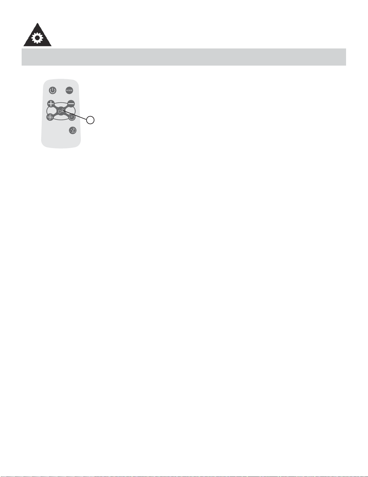
UTILISATION DES BOUTONS DE LA TÉLÉCOMMANDE
Model / Modèle :
R15B
ÉCONOMISEUR D’ÉNERGIE
Cette fonction est disponible lorsque l’appareil est en modes Frais, Sec, et Auto (Auto-Frais
et Auto-Ventilateur modes seulement). Le ventilateur continuera à fonctionner pendant 3
minutes après que le compresseur s’est étendu. Après cela, le ventilateur se met en marche
pendant 2 minutes, avec des intervalles de 10 minutes jusqu’à ce que la température am-
biante de la chambre est plus élevée que la température choisie/réglée. À ce point-là le
compresseur se remet en marche et le refroidissement recommence.
-----------------------------------------------------------------------------------------------------------------------
1
CONSIGNES D’UTILISATION
• Protéger la télécommande contre les températures élevées et éviter l’exposition à la radiation.
• Protéger le récepteur du panneau de contrôle contre les rayons directs du soleil.
• Si la télécommande ne sera pas utilisée pour des périodes prolongées (vacances, etc.), les piles devraient être re-
tirées de la télécommande.
• La télécommande fonctionnera en dedans d’une distance de 8 mètres (26 pi.) du récepteur situé à l’intérieur de l’unité
principale. Toute obstruction entre le récepteur et la télécommande pourrait causer une interférence au signal, ce qui
limiterait la capacité de programmation de l’unité principale.
• Cet appareil numérique de la classe B est conforme à la
Remarque : Cet appareil a été testé et déclaré conforme aux limites imposées aux appareils numériques de classe B, en
vertu de l’alinéa 15 du règlement de la FCC. Ces limites sont destinées à assurer une génère, utilise et peut émettre de
l’énergie radiofréquence et, s’il n’est pas installée utilisé conformément aux instructions, risque de provoquer des inter-
férences nuisibles lors de la réception d’émissions de radio ou de télévision (il suffi t, pour le vérifi er, d’allumer et d’étein-
dre successivement l’appareil); s’il constate de telles interférences, l’utilisateur devra prendre les mesures nécessaires
pour les éliminer. À cette fi n, il devra :
1. Réorienter ou déplacer l’antenne réceptrice.
2. Accroître la distance entre l’appareil et le récepteur.
3. Brancher l’appareil sur une prise de courant appartenant à un autre circuit que celui du récepteur.
4. Chercher de l’aide auprès du détaillant ou d’un technicien en radio ou en télévision expérimenté.
Des changements ou modifi cations non approuvés par l’autorité ayant confi rmé la conformité de l’appareil aux règlements
de la FCC pourraient faire retirer l’autorisation d’utilisation de l’appareil. Cet appareil est conforme à la Section 15 des
réglementations de la FCC. Son utilisation est soumise aux deux conditions suivantes:
1. Cet appareil ne doit pas causer d’interférences nuisibles, et
2. Cet appareil doit accepter toute interférence reçue, y compris les interférences qui pourraient causer un fonctionne-
ment non souhaité.
30
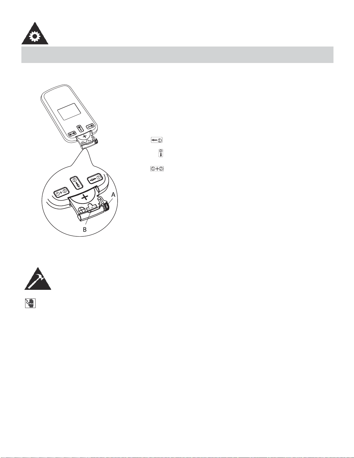
CHANGEMENT DE PILE DE LA TÉLÉCOMMANDE
õ
Ðä
à
ä
ç
õÐ äà
ä
ç
1
2
1
2
+
B
A
1
2
1
2
+
La télécommande est alimentée par une pile bouton installée
dans la partie arrière et protégée par un couvercle. Enlevez la
pile bouton dans la direction indiquée par les fl èches sur l’arrière
de la télécommande.
1. Appuyez légèrement la position « A » avec l’index, dans la
direction indiquée par la fl èche 1.
2. Appuyez sur la position « B » avec le pouce et tirez dessus
dans la direction indiquée par la fl èche 2.
3. Les étapes 1 et 2 doivent être effectuée simultanément afi n
de pouvoir glisser la pile bouton hors du compartiment.
CONSIGNES D’UTILISATION
INSTRUCTIONS D’INSTALLATION
RISQUE DE CHOC ÉLECTRIQUE
Pour éviter la possibilité de blessures corporelles, débrancher l’alimentation de courant à l’unité avant
d’entreprendre l’installation ou le service.
REMARQUE :
Votre climatiseur de chambre a été conçu pour une installation facile dans une fenêtre à châssis à guil-
lotine simple ou double. Cet appareil n’a pas été conçu pour des fenêtres verticales (de type coulissant)
ou pour être installé à travers une paroi.
OUTILS NECESSAIRE POUR INSTALLATION
• Gros tournevis à tête plate
• Crayon
• Clés à douilles
• Niveau
• Clé ajustable ou pinces
• Ruban à mesure
• Tournevis cruciforme
31
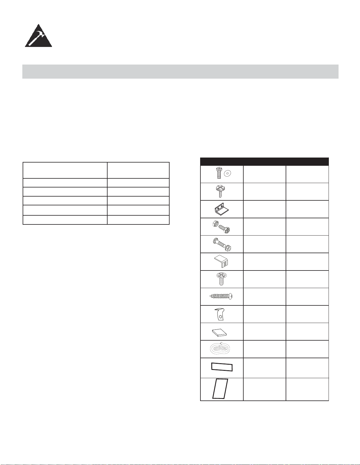
INSTRUCTIONS D’INSTALLATION
AVANT L’INSTALLATION
• Comparez les dimensions de la fenêtre ouverte aux dimensions de votre appareil.
• Vérifi ez l’état de la fenêtre; toutes les parties en bois de la fenêtre doivent être en bon état et en mesure de retenir
soildement toutes les vis nécessaires. Si cela n’est pas le cas, effectuez les réparations nécessaires avant d’installer
l’appareil.
• Vérifi ez l’absence de tout élément pouvant bloquer la circulation de l’air, par exemple, à l’extérieur, des buissons, des
arbres ou des auvents. À l’intérieur, assurez-vous que le mobilier, les rideaux ou les stores ne bloquent pas la circula-
tion de l’air.
• Déballez soigneusement le climatiseur. Enlevez tous les matériaux d’emballage et vérifi ez que toutes les ferrures
fournies pour l’installation sont présentes.
Type de modèle : DAC150BBCWDB
DAC150BBUWDB
Hauteur de l’unité : 17,91”
Largeur de l’unité : 23,62 “
Ouverte de fenêtre minimale : 18 1/2”
Largeur de fenêtre minimale : 27 3/4”
Largeur de fenêtre maximale : 40 1/2”
Vis de blocage de et
rondelle plate 7/16po
(11.1mm) pour les
panneaux de la fenêtre
Vis à tête hexagonale de
1/2po (13mm) de
longueur
Loquet de sécurité
Vis de 1/2po(12.7mm)
longueur et contre-écrou
Boulon à tête plate de ¾ po
de longueur et contre-écrou
Support d’angle pour
appui de fenêtre
Vis de blocage à tête hexag-
onale de 5/6 po de longueur
pour le dispositif de retenue
latéral d’angle supérieur.
Vis de 13/16po(20mm)
Bloque-cadre
2 chacun
7
1
4 chacun
2 chacun
2
10
2
2
Fig. 1 MATÉRIEL D'INSTALLATION
2
Isolant de mousse
pour fenêtre
1
Encart de mousse
Insert de mousse
Calfeutrage
5
2
32
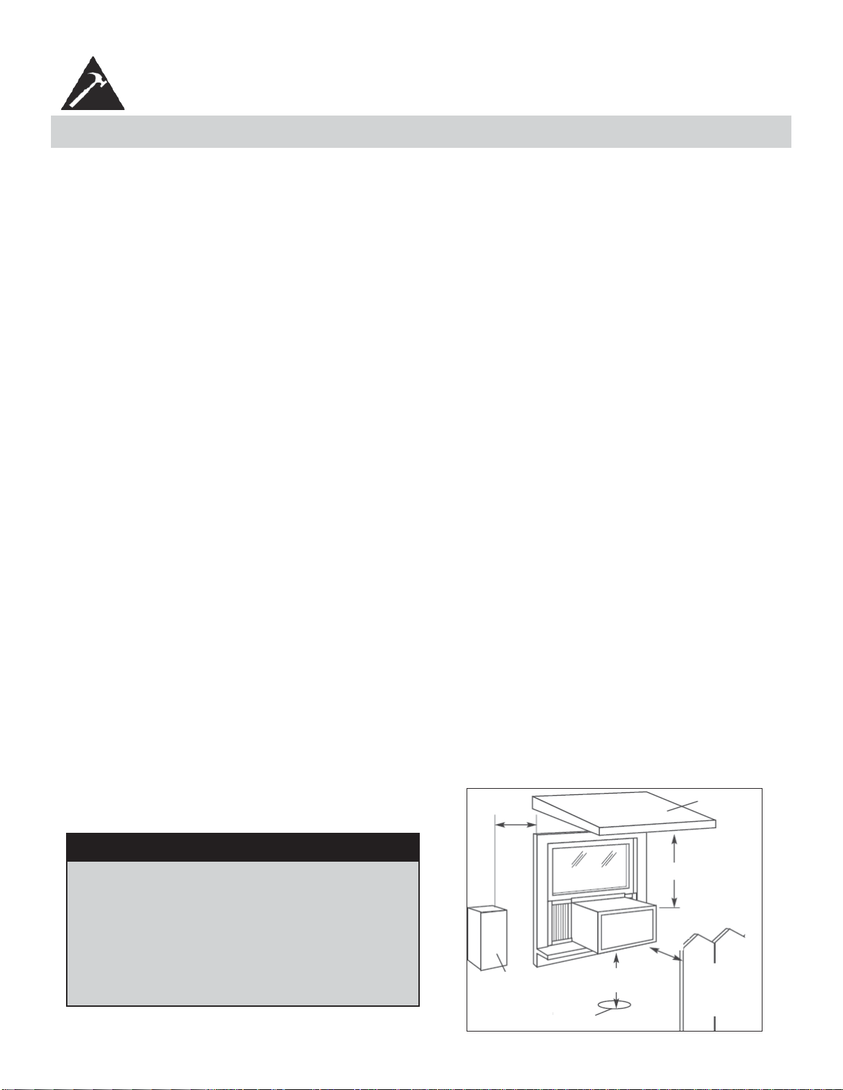
1. Ce climatiseur pour chambre a été conçu pour être installé facilement dans une fenêtre à châssis à guillotine simple
ou double. Cependant, comme le modèle de la fenêtre peut varier, il peut être nécessaire d’y faire quelques modifi ca-
tions pour une installation sécuritaire et appropriée.
2. Assurez-vous que la fenêtre et son châssis sont structurellement solides et exempts de bois sec et pourri.
3. Pour un maximum d’effi cacité, installez le climatiseur sur le côté de la maison ou de l’immeuble qui se trouve plus
souvent à l’ombre qu’au soleil. Si l’appareil est directement sous les rayons du soleil, installer un auvent pour protéger
l’unité.
4. Laissez suffi samment d’espace libre autour du caisson pour permettre une ample circulation d’air à travers l’appareil.
Voir Fig. 2. L’arrière de l’appareil doit donner sur l’extérieur de la maison et non pas dans un garage ou à l’intérieur
d’un immeuble. Tenez l’appareil aussi loin que possible de tout obstacle ou obstruction et à au moins 30 po (76 cm)
au-dessus du plancher ou du sol. Il ne faut pas que les rideaux ou d’autres objets à l’intérieur de la pièce puissent
bloquer le fl ux d’air.
5. Assurez-vous que la prise électrique appropriée se trouve à la portée de l’installation. N’utilisez qu’un circuit à prise
unique calculé à 15 ampères. Tout le câblage doit être conforme aux codes électriques locaux et nationaux.
6. N’insallez PAS l’appareil à un endroit où on soupçonne une fuite de gaz combustibles. Votre climatiseur peut tomber
en panne dans une atmosphère qui contient des huiles (y compris des huiles pour machines), des gaz sulfurés, ou s’il
est près de sources d’eau chaude, etc.
REMARQUE : Votre appareil a été conçu pour que la condensation s’évapore dans des conditions normales. Cependant,
en présence d’une humidité extrême, un surplus de condensation peut provoquer un débordement de la cuvette de base
vers l’exterieur. L’appareil doit être installé de telle sorte que l’écoulement de la condensation ne se déverse pas sur des
passants ou sur des propriètés avoisinantes.
REMARQUE : Il est normal que l’appareil coule légèrement, surtout lors des journées excessivement humides.
CONSIGNES D’INSTALLATION
EMPLACEMENT
Auvent
Clôture,
mur ou
autre
obstacle
Sol
Obstacle
latéral
20 po
(50,8
cm)
min.
30 po (76 cm)
min.
20 po (50,8 cm)
12 po (30,5 cm) min.
min.
Fig. 2
REMARQUE : Conservez le carton d’expédition et le matériel d’emballage pour futur entreposage ou transport de l’ap-
pareil. Ôtez l’appareil du carton, le sac en plastique qui contient la trousse de quincaillerie nécessaire pour l’installation
de votre climatiseur. Veuillez vérifi er le contenu de la trousse de quincaillerie d’installation en le comparant à la liste de
vérifi cation du modèle correspondant, et ce, avant l’installation de l’appareil. Voir Fig. 1.
REMARQUE : Votre climatiseur de chambre a été conçu pour une installation facile dans une fenêtre à châssis à guil-
lotine simple ou double. Cet appareil n’a pas été conçu pour des fenêtres verticales (de type coulissant) ou pour être
installé à travers une paroi.
MISE EN GARDE
Comme le compresseur se trouve du côté des
commandes (côté gauche), ce côté est plus lourd
et plus diffi cile à manipuler. Un soutien inapproprié
du côté des commandes de l’appareil peut causer
des blessures et endommager l’appareil et d’autres
biens moviliers. C’est pourquoi il est recommandé
que quelqu’un vous aide au cours de l’installation
de cet appareil.
33
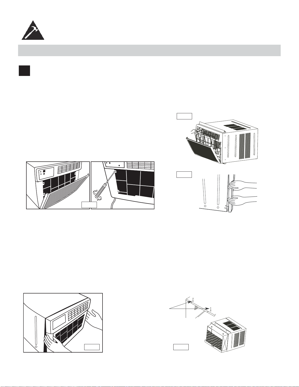
FIXATION DANS LA FENÊTRE
1
Enlèvement du bâti :
1. Tirez le panneau avant vers le bas et enlevez le fi ltre (voir Fig. A).
2. Tirez vers le haut le panneau avant et mettez-le de côté.
3. Trouvez les quatre (4) vis avant et enlevez-les (Fig. B). Ces vis serviront à réinstaller le panneau avant plus tard.
4. Enlevez le panneau avant des parois du caisson en faisant levier Fig. C.
Fig. B
Fig. A
Fig. C
5. Soulevez doucement avant outre de l’unité et le placez à un côté (Voir Fig. D).
6. Enlevez les vis d’expédition du dessus de l’unité et également du côté par la base s’installé.
7. Tenez le bâti tout en tirant sur la poignée basse, et enlevez soigneusement le climatiseur de le bâti.
8. Ajoutez deux insertions de mousse aux trous dans le dessus de le bâti d’où des vis de expédition ont été
enlevées (Fig. E).
9. Votre unité peut venir avec l’empaquetage interne. Cet empaquetage doit être enlevé avant d’installer le
climatiseur de nouveau dans le bâti.
Fig. D
Fig. E
la mousse
insère
CONSIGNES D’INSTALLATION
34
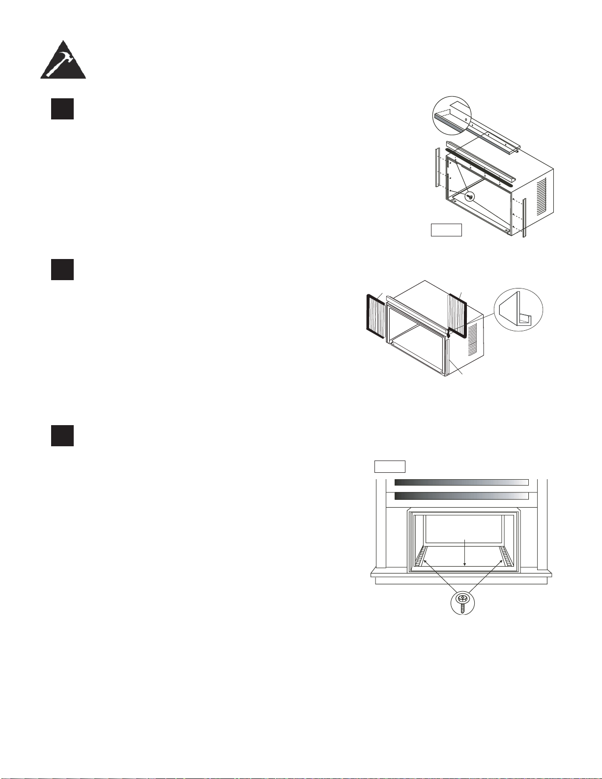
2
Installer l’angle au-dessus et support côté
1. Attacher le joint de mousse pour dépasser l’angle au-dessus
des trous selon Fig. F.)
2. Installer l’angle au-dessus et latéral de retenue au cabinet selon Fig. F.
3
Assembler la fênetre panneaux de remplissage (voir Fig.
G) :
1. Placer le cabinet sur le plancher, un banc, ou une table.
2. Glisser la fenêtre le cadre de panneau de remplissage
dans le sommet (en forme de L) et le fond (en forme
d’U) les chaînes. Les volets sont identifi és (sur le cadre)
comme gauche et la droite.
3. La tête de rondelle d’insertion verrouillant des vis (2)
dans les trous
4. dans la première jambe de cadre de panneau de rem-
plissage. Ne pas entièrement resserrer. Permettre à la
jambe pour glisser librement. Les vis seront resserrées
plus tard.
cadre en
plastique
La canal un forme de
« U »
fenêtre panneaux de
remplissage
Le support en forme
de « L »
4
Installez l’angle au-dessus et support côté
1. Ouvrez la fenêtre et marquez le centre du fi lon-
couche de fenêtre.
2. Placez le cabinet dans la fenêtre avec le canal
inférieur de « U » de le cabinet fermement posé
audessus du fi lon-couche de fenêtre. Réduisez la
fenêtre temporairement derrière le dessus « L »
support pour tenir le cabinet en place.
3. Décalez le cabinet laissé ou droit en tant que
nécessaire d’aligner le centre du cabinet sur la ligne
centrale marquée sur le fi lon-couche de fenêtre.
4. Attachez le cabinet au fi lon-couche de fenêtre avec
2 vis (vous pouvez vouloir perforer des trous).
5. Ajoutez le joint inférieur de rail au-dessus des vis au
fi lon-couche de fenêtre. See Fig. H.
CONSIGNES D’INSTALLATION
5/16in. (8mm)
hexagonale
Fig. F
Fig. H
joint inférieur
de rail
3/4in.(19mm) vis tête
hexagonale
35
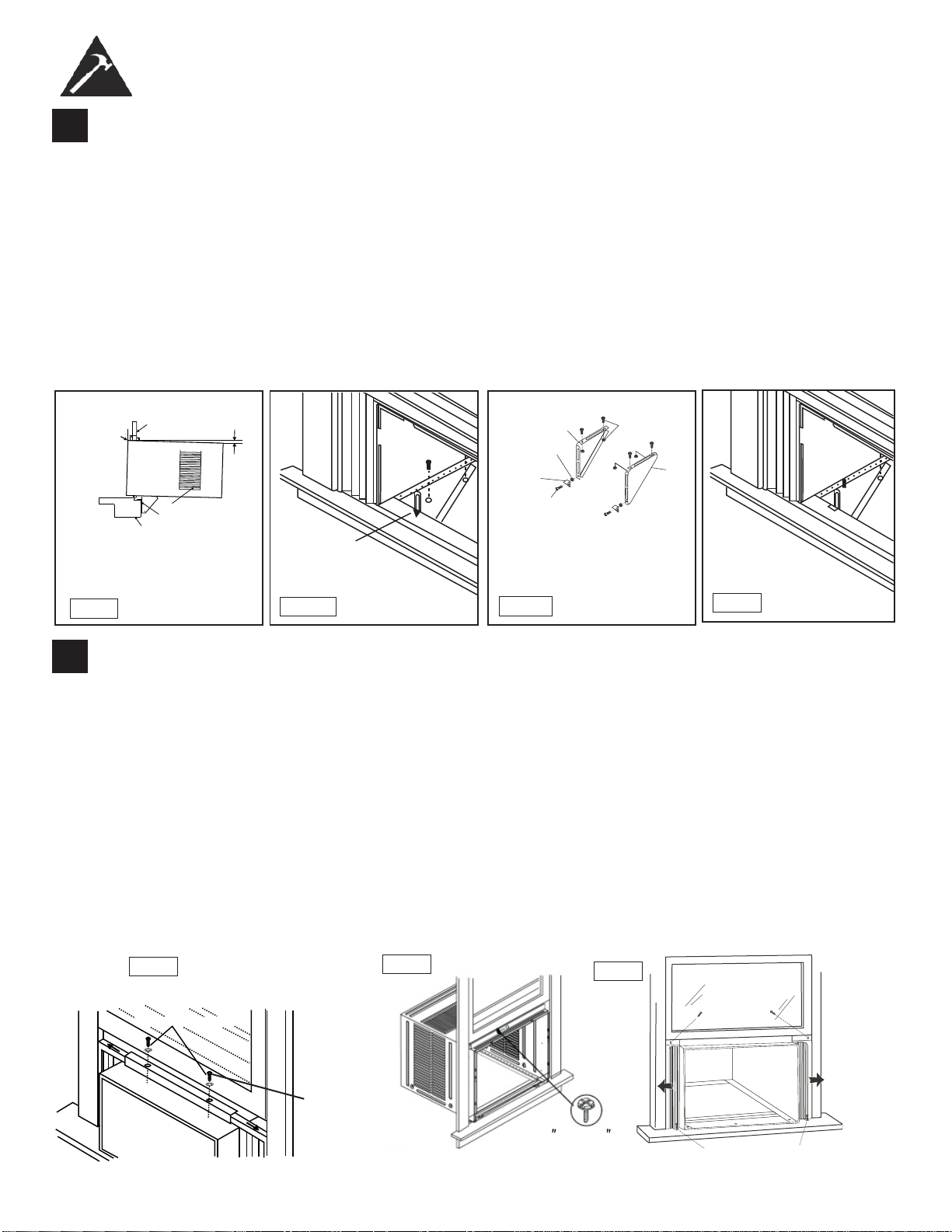
5
Installation du support
1. Tenez chaque support au ras de l’extérieur de l’appui de fenêtre, et fi xez-le contre le bas du caisson, tel qu’illustré
dans la Fig. J
1. Tracez un repère pour les supports au niveau supérieur de l’appui de fenêtre, puis enlevez-les.
2. Assemblez le support d’ancrage de l’appui de fenêtre avec les pieds de support extérieurs sur la position marquée,
tel qu’illustré dans la Fig. J2. Serrez à la main, mais de manière à ce que des changements puissent être apportés
ultérieure ment. Assurez-vous que le climatiseur est incliné vers l’extérieur de 3 ou 4 degrés, tel que montré sur
Fig. I. Lors de l’usage normal, il ne devrait jamais y avoir d’eau condensée qui s’échappe par le trou de drainage, si
l’installation est bien faite. Si vous remarquez un égouttement d’eau, vérifi ez l’angle d’inclinaison du climatiseur et
faites les ajustements nécessaires. Par contre, il est normal d’avoir un égouttement d’eau pendant les journées très
humides. Mesurez l’angle d’inclinaison du bord du caisson. L’intervalle H devrait être d’environ 1 1/4 à 1 5/8 pouces.
3. Installez les supports (sur lesquels les supports d’ancrage de l’appui de fenêtre sont fi xés) dans le bon orifi ce dans le
bas du caisson, tel qu’illustré dans la Fig. K.
4. Serrez à fond les 6 boulons.
6
Déployez les panneaux de calage de la fenêtre
1. Soulevez avec précaution la fenêtre pour exposer les vis de panneau. Desserrez les vis pour faire glisser facilement
les panneaux de remplissage.
2. Étendez les panneaux pour remplir la fenêtre complètement. L’utilisation de deux vis 7/16 po (12 mm) de blocage et
une rondelle plate, serrez les vis de verrouillage sur le dessus (fi g. L1).
3. Fermez la fenêtre derrière l’angle au sommet.
4. Fixez l’angle haut au cadre de la fenêtre en utilisant un peu de 3/32 pour percer un trou à travers le trou dans le
milieu de l’angle supérieur dans le cadre de la fenêtre, et insérez un vis ½ pouce (12.5mm) à tête hexagonale de
blocage à travers le trou dans le milieu de l’angle en haut dans le cadre de la fenêtre, voir Fig. L2.
5. Étendre les panneaux de remplissage de la fenêtre contre le cadre de la fenêtre.
6. Utiliser une mèche de 1/8 pouce pour percer un trou à travers le trou dans la jambe du dessus de chaque panneau
de la fenêtre et dans le châssis de la fenêtre (fi g. L3). Connectez les deux avec un ½ vis à tête hexagonale longue.
7. Fixer le verrou de cadre à l’appui de fenêtre en utilisant un 13/16” (20mm) vis de chaque côté, comme indiqué dans
la fi gure. L3.
CONSIGNES D’INSTALLATION
Fig. J1
Fig. J2
Fig. K
Mesurez
l’angle
d’inclinaison
du bord du
caisson.
Rebord de
la fenêtre
Le cadre de
la fenêtre
Environ
óWRǫ
Support d’angle pour
appui de fenêtre
Persiennes latérales
Fig. I
Repère
Gauche
Contre-écrou
Support
d’ancrage de
l’appui de
fenêtre
Boulon à
tête plate
2 de chaque pour chaque
support
Droit
Vis de ½ po de
longueur et
contre-écrous
H
36
Vis de blocage
7/16" vis de
blocage et
and rondelle
Fig.L2
1/ 2 longue
VIS À TÊTE
HEXAGONALE
Fig.15B
1/2 po. (13mm) longue
vis à tête hexagonale
13/16 po. (20mm) vis et verrou de châssis (2)
Fig. L3
(2
)
1.
Fig.L1
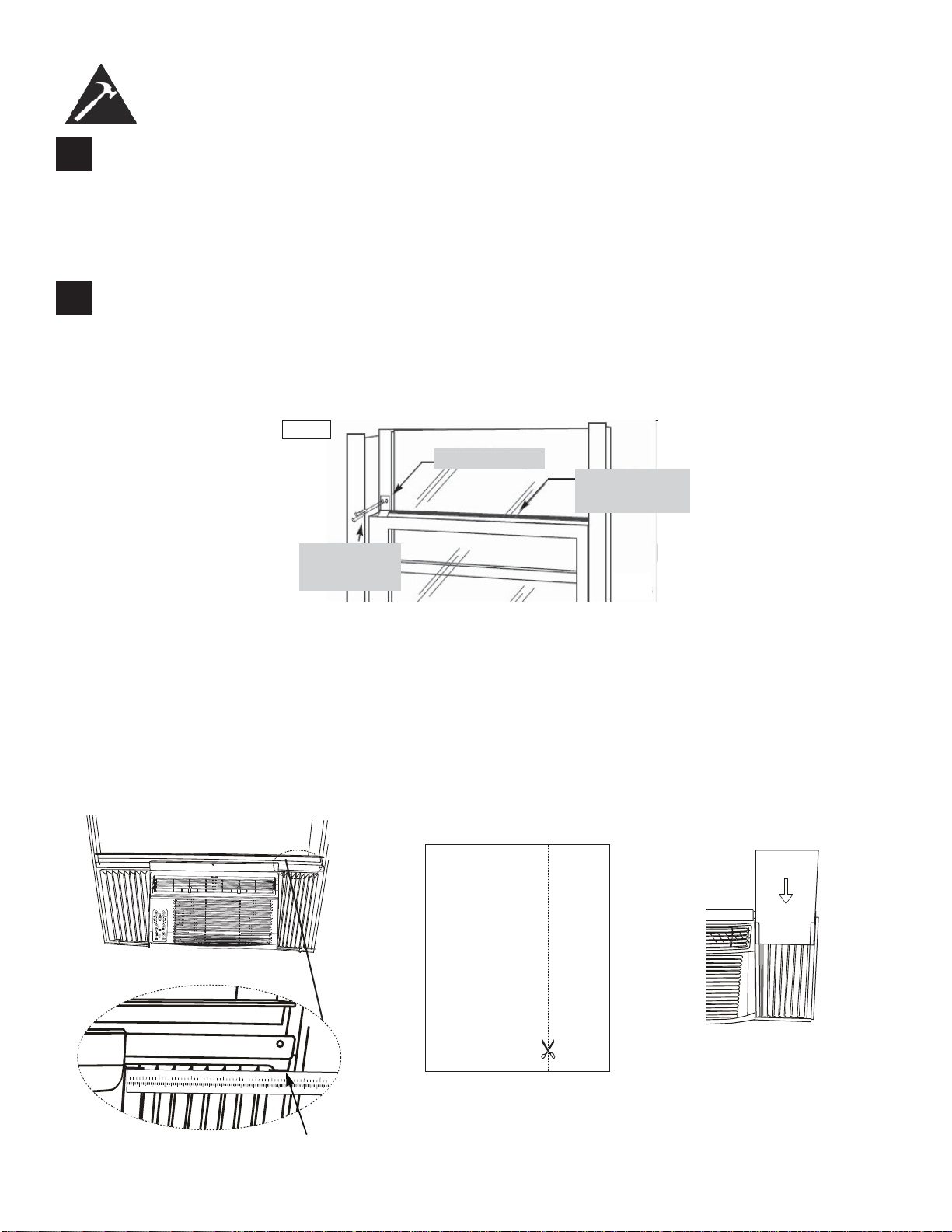
7
Installation du loquet et du joint d’étanchéité du châssis de fenêtre
1. Coupez le joint d’étanchéité du châssis de fenêtre selon la largeur de la fenêtre. Insérez-le dans l’espace
entre le châssis supérieur et le châssis inférieur (Fig. M).
2. Fixez le loquet de sécurité à angle droit tel qu’illustré dans la Fig. M.
CONSIGNES D’INSTALLATION
8
Installez le bâti dans le caisson et posez le panneau avant sur l’appareil :
1. Soulevez le climatiseur et glissez-le avec précaution dans le caisson, en laissant dépasser 6 po.
2. N’APPUYEZ PAS sur les commandes ou les serpentins.
3. Assurez-vous que le bâti est bien logé vers l’arrière du caisson.
4. L’installation du panneau avant est l’inverse de son enlèvement, décrit dans la section 1 («Enlèvement du
bâti»).
Loquet de sécurité
Vis à tête
hexagonale de 1/2
po (19mm) de
longueur
Joint d’étanchéité
pour le châssis de
fenêtre
Fig.M
37
Installer le Mousse éconergétique
• Après que l’appareil est installée dans la fenêtre, mesurer la largeur du rideau sur le côté
• Si nécessaire, coupez le mousse pour le réduire au même largeur que le rideau
• Insérez le mousse dans le rideau
• Répétez pour l’autre côté (Voyez en bas)
REMARQUE : Appliquer le calfeutrage en cas de besoin (les fi ssures et les espaces entre l’insert de mousse, kit
de fenêtre et cadre de fenêtre) qui est fourni.
123456
789
10 1
1
12
13 14 15 16 17
12
34
56
Étape 1 Étape 3Étape 2
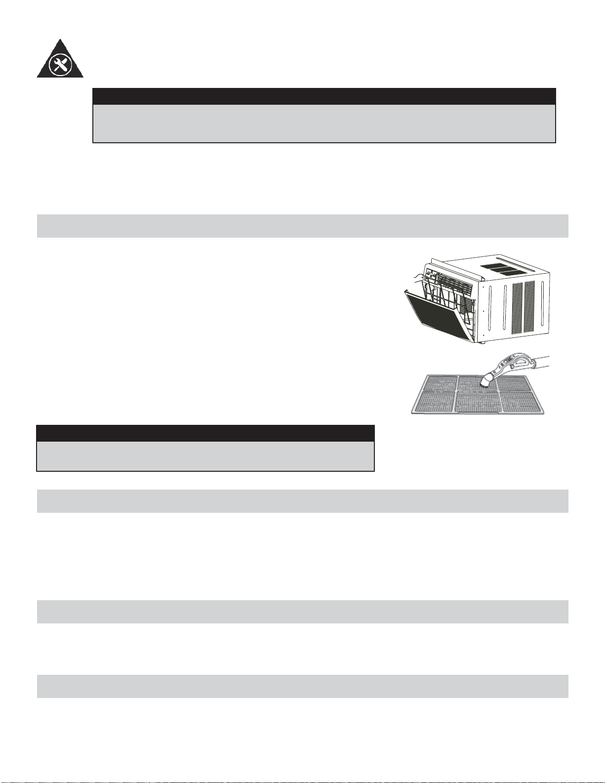
NETTOYAGE DU CAISSON
• Assurez-vous de débrancher le climatiseur afi n d’éliminer les risques de choc ou d’incendie. Le caisson et le devant
peuvent être époussetés au moyen d’un chiffon sans huile ou lavés au moyen d’un chiffon doux trempé dans une
solution d’eau chaude et de liquide à vaisselle doux. Rincez à fond et essuyez pour sécher.
• Assurez-vous d’essorer le chiffon avant d’essuyer autour des commandes. Un excédent d’eau dans le commandes
ou autour de celles-ci peut endommager le climatiseur.
ENTREPOSAGE PENDANT L’HIVER
Si vous prévoyez d’entreposer le climatiseur pendant l’hiver, enlevez-le soigneusement de la fenêtre en suivant les in-
structions d’installation. Recouvrez-le d’une feuille de plastique ou remettez-le dans son carton d’origine. Rangez toujours
l’appareil en position verticale.
MISE AU REBUT
Vérifi ez le respect des réglementations locales concernant la mise au rebut approuvée et sécurisée de cet appareil.
SOINS ET ENTRETIEN
38
LE NETTOYAGE DU FILTRE À AIR
MISE EN GARDE
Avant de procéder à l’entretien du climatiseur, assurez-vous de débrancher le cordon d’ali-
mentation de la prise électrique afi n d’éliminer les risques de choc électrique ou d’incendie.
• N’utilisez PAS de l’essence, un produit chimique, diluant ou autre sur un climatiseur, car ces substances peuvent
endommager la fi nition de la peinture et déformer des pièces en plastique.
• N’essayez jamais de verser de l’eau directement sur le climatiseur, car cela provoque une détérioration de l’isolation
électrique.
Il faut vérifi er le fi ltre à air au moins une fois par mois pour voir s’il est néces-
saire de le nettoyer. Les particules piégées par le fi ltre peuvent s’accumuler
et causer du givre sur les serpentins de refroidissement.
• Poussez sur la poignée de l’évent pour la mettre sur la position fermée.
• Ouvrez le panneau avant.
• Prenez le fi ltre et tirez vers le haut puis vers l’extérieur pour le sortir.
• Lavez le fi ltre au moyen d’un liquide à vaisselle et d’eau chaude. Rincez
le fi ltre à fond.
• Secouez doucement le fi ltre pour enlever l’excès d’eau. Assurez-vous
que le fi ltre est complètement sec avant de le remettre en place.
• Vous pouvez également utiliser un aspirateur pour nettoyer le fi ltre.
Remarque : n’utilisez jamais d’eau dont la température est supérieure à 40°C
(104°F) pour nettoyer le fi ltre à air.
MISE EN GARDE
Ne jamais faire fonctionner cette unité sans le fi ltre à air à sa place,
comme ceci peut avoir pour résultat des dommages à l’unité.
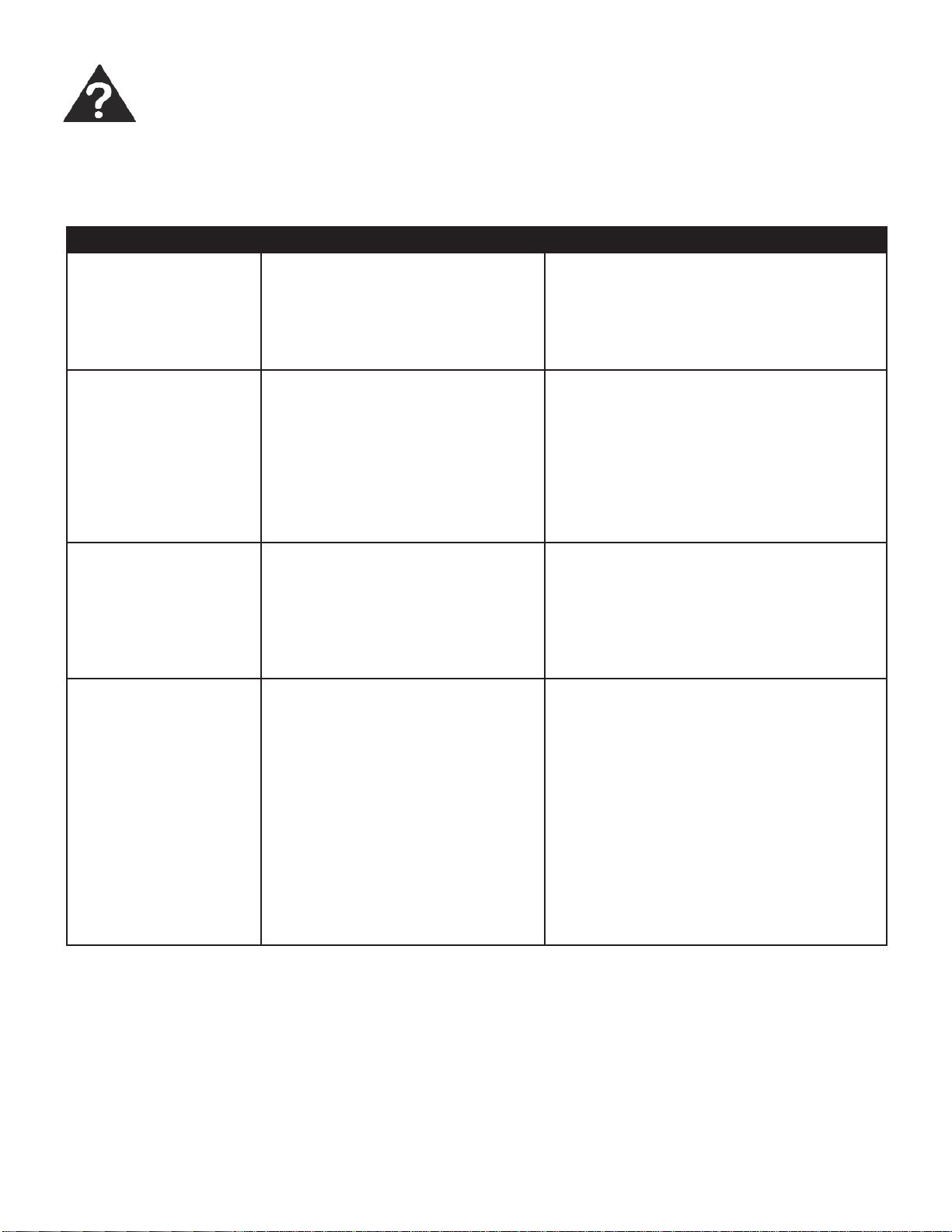
PROBLEME CAUSE PROBABLE SOLUTION
L’appareil ne fonctionne
pas
• Panne de courant
• L’appareil n’est pas branché cor-
rectement
• Le coup-circuit est déclenché
• La commande est sur arrêt (off)
• Attendez que le courant soit rétabli
• Branchez l’appareil correctement
• Appuyez sur le bouton Réinitialisation (Re-
set) après avoir résolu le problème
• Mettez la commande sur la position marche
et réglez la valeur désirée
L’air sortant de l’appar-
eil ne semble pas assez
froid
• Température de la pièce inférieure
à 17°C (62 °F)
• Le capteur de température touche
le serpentin de refroidissement
(derrière le fi ltre à air)
• La température est réglée à une
valeur trop élevée
• Le compresseur est arrêté lors du
changement de modes
• Ne refroidit pas tant que la température de
la pièce n’est pas supérieure à 17°C (62°F)
• Redressez le tube pour l’éloigner du ser-
pentin
• Réglez à une température inférieure
• Attendez environ 3 minutes et écoutez
afi n de vous assurer que le compresseur
redémarre en mode Refroidissement.
Le climatiseur refroidit
la pièce, mais la pièce
est trop chaude-for-
mation de givre sur le
serpentin de refroidisse-
ment, derrière le pan-
neau avant décoratif
• Température extérieure inférieure à
17°C (62°F)
• Le fi ltre à air est peut-être sale
• Le thermostat est réglée à une
valeur troup basse pour refroidir
pendant la nuit
• Pour dégivrer le serpentin, mettez l’appareil
en mode VENTILATION SEULEMENT
• Nettoyez le fi ltre conformément aux instruc-
tions
• Réglez la température à une valeur plus
élevée
Le climatiseur refroidit
la pièce, mais la pièce
est trop chaude -
AUCUN formation de
givre sur le serpentin de
refroidissement, der-
rière le panneau avant
décoratif
• La fi ltre à air est sale- la circulation
de l’air est restreinte
• La température est réglée à une
valeur troup élevée
• Les louvres d’air sont mal position-
nés
• Obstruction de l’avant de l’appareil
(p. ex., par des rideaux), ce qui
restreint la circulation de l’air
• Les portes, les fenêtres ou les
grilles à registre sont ouvertes, ce
qui fait que l’air froid s’échappe
• L’appareil vient d’être mis en
marche dans une pièce chaude
• Nettoyez le fi ltre à air
• Réglez la température à une valeur plus
basse
• Orientez les louvres de manière à obtenir
une meilleure répartition de l’air
• Enlevez les obstructions devant l’appareil
• Fermez les portes, les fenêtres et les grilles
à registre
• Laissez plus de temps pour l’élimination de
la « chaleur emmagasinée » de la pièce
De temps en temps, un problème mineur peut se poser et un appel de service peut ne pas être nécessaire. Employez ce
guide de dépannage pour une solution possible. Si l’unité continue à fonctionner incorrectement, communiquez avec un
dépôt autorisé de service ou appelez au numéro sans frais de Danby : 1-800-263-2629.
DÉPANNAGE
39
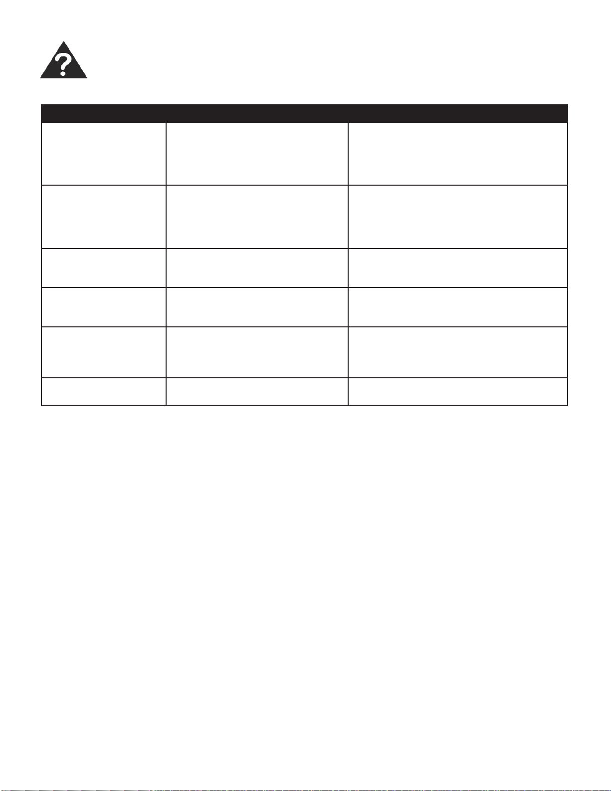
Le climatiseur se met
en marche et s’arrête
rapidement
• La fi ltre à air est sale- la circulation
de l’air est restreinte
• La température extérieure est
extrêmement chaude
• Nettoyez le fi ltre à air
• Réglez la vitesse du ventilateur à une
valeur plus élevée afi n que l’air passe entre
les serpentins de refroidissement plus
souvent
L’appareil est bruyant
en mode Refroidisse-
ment
• Sons causés par la circulation de
l’air
• Vibration des fenêtres
• Cela est normal. Si le bruit est trop fort,
réglez le ventilateur à une vitesse moins
élevée
• Mauvaise installation- consultez les instruc-
tions d’installation ou l’installateur
De l’eau dégoutte À
L’INTÉRIEUR lorsque
l’appareil refroidit
• Installation incorrecte • Inclinez le climatiseur légèrement vers l’ex-
térieur pour permettre à l’eau de s’écouler
De l’eau dégoutte À
L’EXTÉRIEUR lorsque
l’appareil refroidit
• L’appareil élimine de grandes
quantités d’humidité d’une pièce
humide
• C’est normal par temps très humide
Le capteur à distance se
désactive trop rapide-
ment
• Le télécommande est hors de
portée
• Le signal de la télécommande est
bloque
• Placez la télécommande dans un rayon de
20 pi et 180° de l’avant de l’appareil
• Enlevez les obstructions
La pièce est trop froide • La température est réglée à une
valeur trop basse
• Augmentez la température préréglée
DÉPANNAGE (suite)
PROBLEME CAUSE PROBABLE SOLUTION
40
LIMITED IN-HOME APPLIANCE WARRANTY
This quality product is warranted to be free from manufacturer’s defects in material and workmanship, provided that the unit is used under the normal operating
conditions intended by the manufacturer.
This warranty is available only to the person to whom the unit was originally sold by Danby Products Limited (Canada) or Danby Products Inc. (U.S.A.) (hereafter
“Danby”) or by an authorized distributor of Danby, and is non-transferable.
TERMS OF WARRANTY
Plastic parts, are warranted for thirty (30) days only from purchase date, with no extensions provided.
First Year
During the rst twelve (12) months, any functional parts of this product found to be defective, will be repaired or replaced, at warrantor’s
option, at no charge to the ORIGINAL purchaser.
To obtain
Danby reserves the right to limit the boundaries of “In Home Service” to the proximity of an Authorized Service Depot. Any app liance
Service
requiring service outside the limited boundaries of “In Home Service” , it will be the consumer’s responsibility to transport the appliance (at
their own expense) to the original retailer (point of purchase) or a service depot for repair. See “Boundaries of In Home Serv ice” below.
Contact your dealer from whom your unit was purchased, or contact your nearest authorized Danby service depot, where service
must be performed by a qualied service technician.
If service is performed on the units by anyone other than an authorized service depot, or the unit is used for commercial appli cation, all
obligations of Danby under this warranty shall be void.
Boundaries of
If the appliance is installed in a location that is 100 kilometers (62 miles) or more from the nearest service center your unit must be
In Home Service
delivered to the nearest authorized Danby Service Depot, as service must only be performed by a technician qualied and certif ied for
warranty service by Danby. Transportation charges to and from the service location are not protected by this warranty and are t he
responsibility of the purchaser.
Nothing within this warranty shall imply that Danby will be responsible or liable for any spoilage or damage to food or other c ontents of this appliance, whether due
to any defect of the appliance, or its use, whether proper or improper.
EXCLUSIONS
Save as herein provided, Danby, there are no other warranties, conditions, representations or guarantees, express or implied, m ade or intended by Danby or its
authorized distributors and all other warranties, conditions, representations or guarantees, including any warranties, conditio ns, representations or guarantees
under any Sale of Goods Act or like legislation or statue is hereby expressly excluded. Save as herein provided, Danby shall no t be responsible for any damages
to persons or property, including the unit itself, howsoever caused or any consequential damages arising from the malfunction o f the unit and by the purchase of
the unit, the purchaser does hereby agree to indemnify and hold harmless Danby from any claim for damages to persons or propert y caused by the unit.
GENERAL PROVISIONS
No warranty or insurance herein contained or set out shall apply when damage or repair is caused by any of the following:
1) Power failure.
2) Damage in transit or when moving the appliance.
3) Improper power supply such as low voltage, defective house wiring or inadequate fuses.
4) Accident, alteration, abuse or misuse of the appliance such as inadequate air circulation in the room or abnormal operating con ditions
(extremely high or low room temperature).
5) Use for commercial or industrial purposes (ie. If the appliance is not installed in a domestic residence).
6) Fire, water damage, theft, war, riot, hostility, acts of God such as hurricanes, oods etc.
7) Service calls resulting in customer education.
8) Improper Installation (ie. Building-in of a free standing appliance or using an appliance outdoors that is not approved for out door application).
Proof of purchase date will be required for warranty claims; so, please retain bills of sale. In the event warranty service is required, present this document to our
AUTHORIZED SERVICE DEPOT.
Danby Products Limited
PO Box 1778, Guelph, Ontario, Canada N1H 6Z9
Telephone: (519) 837-0920 FAX: (519) 837-0449
Danby Products Inc.
PO Box 669, Findlay, Ohio, U.S.A. 45840
Telephone: (419) 425-8627 FAX: (419) 425-8629
04/09
1-800-263-2629
Warranty Service
In-home
Si l'appareil est installé à plus de 100 kilomètres (62 milles) du centre de service le plus proche, il doit
être livré à l'atelier de réparation autorisé par Danby le plus proche, car l'entretien doit uniquement être
réalisé par un technicien qualifié et certifié pour effectuer un entretien couvert par la garantie de Danby.
Les frais de transport entre votre domicile et le lieu de l'entretien ne sont pas couverts par la présente
garantie et doivent être acquittés par l'acheteur.
Pendant les premiers douze (12) mois, toutes les pièces fonctionnelles de ce produit qui s’avèrent
défectueuses seront réparées ou remplacées, selon le choix du garant, sans frais à l’acheteur INITIAL.
Le client sera responsable pour le transport et tous les frais d’expédition de tout appareil exigeant le
service au dépot de service autorisé le plus proche. S’adresser au détaillant qui a vendu l’appareil, ou à
la station technique agréée de service la plus proche, où les réparations doivent être effectuées par un
technicien qualifié. Si les réparations sont effectuées par quiconque autre que la station de service
agréée où à des fins commerciales, toutes les obligations de Danby en vertu de cette garantie seront
annulées.
Premiers 12 mois
Pour bénéficier
du service
Limites de
l’entretien à
domicile
GARANTIE LIMITÉE SUR
APPAREIL ÉLECTROMÉNAGER À DOMICILE
Cet appareil de qualité est garanti exempt de tout vice de matière première et de fabrication, s’il est utilisé dans les conditions
normales recommandées par le fabricant.
Cette garantie n’est offerte qu’à l’acheteur initial de l’appareil vendu par Danby Products Limited (Canada) ou Danby Products
Inc. (E.- U.A.) (ci-après « Danby ») ou par l’un des ses distributeurs agréés et elle ne peut être transférée.
CONDITIONS
Les pièces en plastique sont garanties pendant trente (30) jours seulement à partir de la date de l’achat, sans aucune prolon-
gation prévue.
Aucune partie de la garantie ne prévoit implicitement que le fabricant sera tenu responsable des dommages subis par les
aliments ou d’autres types de contenu, qu’ils soient causés par la défectuosité de l’appareil ou par son usage adéquat ou
inadéquat.
EXCLUSIONS
En vertu de la présente, il n’existe aucune autre garantie, condition ou représentation, qu’elle soit exprimée ou tacite, de façon
manifeste ou intentionnelle, par Danby ou ses distributeurs agréés. De même, sont exclues toutes les autres garanties,
conditions ou représentations, y compris les garanties, conditions ou représentations en vertu de toute loi régissant la vente
de produits ou de toute autre législation ou règlement semblables. En vertu de la présente, Danby ne peut être tenue respon-
sable en cas de blessures corporelles ou des dégâts matériels, y compris à l’appareil, quelle qu’en soit les causes. Danby ne
peut pas être tenue responsable des dommages indirects dus au fonctionnement défectueux de l’appareil. En achetant
l’appareil, l’acheteur accepte de mettre à couvert et de dégager Danby de toute responsabilité en cas de réclamation pour
toute blessure corporelle ou tout dégât matériel causé par cet appareil.
CONDITIONS GÉNÉRALES
La garantie ou assurance ci-dessus ne s’applique pas si les dégâts ou réparations sont dus aux cas suivants :
1) Panne de courant.
2) Dommage subis pendant le transport ou le déplacement de l’appareil.
3) Alimentation électrique incorrecte (tension faible, câblage défectueux, fusibles incorrects).
4) Accident, modification, emploi abusif ou incorrect de l’appareil tel qu'une circulation d'air inadéquate dans la pièce ou des
conditions de fonctionnement anormales (température extrêmement élevée ou basse).
5) Utilisation dans un but commercial ou industriel (à savoir, si l'appareil n'est pas installé dans un domicile résidentiel).
6) Incendie, dommages causés par l’eau, vol, guerre, émeute, hostilités, cas de force majeure (ouragan, inondation, etc.).
7) Visites d’un technicien pour expliquer le fonctionnement de l’appareil au propriétaire.
8) Installation inappropriée (par exemple, encastrement d'un appareil autoportant, ou utilisation extérieure d'un appareil non
conçu à cet effet). Une preuve d’achat doit être présentée pour toute demande de réparation sous garantie. Prière de garder
le reçu. Pour faire honorer la garantie, présenter ce document à la station technique agréée ou s’adresser à :
Service sous garantie
Service au domicile
Danby Products Limited
PO Box 1778, Guelph, Ontario, Canada N1H 6Z9
Téléphone : (519) 837-0920 Télécopieur: (519) 837-0449
Danby Products Inc.
PO Box 669, Findlay, Ohio, U.S.A. 45840
Téléphone: (419) 425-8627 Télécopieur: (419) 425-8629
1-800-263-2629
03/14
All repair parts are available for purchase or special
order when you visit your nearest service depot. To
request service and/or the location of the service depot
nearest you, call the TOLL FREE number.
When requesting service or ordering parts, always pro-
vide the following information:
• Product Type
• Model Number
• Part Number
• Part Description
Toutes les pièces de rechange ou commandes spécia-
les sont disponibles à votre centre de service régional
autorisé. Pour obtenir le service et/ou la localité de
votre centre de service régional, signalez le NUMÉRO
D’APPEL SANS FRAIS.
Ayez les renseignements suivants à la portée de la main
lors de la commande de pièce ou service:
• Type de produit
• Numéro de modèle
• Numéro de pièce
• Description de la pièce
MODEL • MODÈLE
1-800-26-
(1-800-263-2629)
Printed in China
Imprimé en Chine
Danby Products Limited, Guelph, ON, Canada N1H 6Z9
Danby Products Inc., Findlay, Ohio, USA 45840
AIR CONDITIONER CLIMATISEUR
DAC150BBCWDB / DAC150BBUWDB