LEVA24SS300-B
LEVA24WH300-B
LEVA24BK300-B
LEVA30SS300-B
LEVA30WH300-B
LEVA30BK300-B
LEVA36SS300-B
LEVA36WH300-B
LEVA36BK300-B
LEVT30SS400-B
LEVT36SS400-B
Installation Instructions
Use and Care Information
Instructions d'installation
Utilisez et d'entretien
Levante I Levante II

2
READ AND SAVE THESE INSTRUCTIONS BEFORE YOU START
INSTALLING THIS RANGEHOOD
WARNING: - TO REDUCE THE RISK OF A RANGE TOP GREASE FIRE:
a) Never leave surface units unattended at high settings. Boilovers cause smoking and
greasy spillovers that may ignite. Heat oils slowly on low or medium setting.
A KV@XRSTQMGNNC.-VGDMBNNJHMF@SGHFGGD@SNQVGDMl@LADHMFENNCHD"QDODR
Suzette, Cherries Jubilee, Peppercorn Beef Flambé).
c) Clean ventilating fans frequently. Grease should not be allowed to accumulate on fan
NQkKSDQ
d) Use proper pan size. Always use cookware appropriate for the size of the surface element.
WARNING: - TO REDUCE THE RISK OF INJURY TO PERSONS IN THE EVENT OF A
RANGE TOP GREASE FIRE, OBSERVE THE FOLLOWING*:
@2,.3'$1%+ ,$2VHSG@BKNRDkSSHMFKHCBNNJHDRGDDSNQLDS@KSQ@XSGDMSTQMNEESGDATQMDQ
!$" 1$%4+3./1$5$-3!41-2(ESGDl@LDRCNMNSFNNTSHLLDCH@SDKX$5 "4 3$
AND CALL THE FIRE DEPARTMENT.
b) NEVER PICK UP A FLAMING PAN - You may be burned.
c) DO NOT USE WATER, including wet dishcloths or towels - a violent steam explosion will
result.
d) Use an extinguisher ONLY if:
1. You know you have a Class ABC extinguisher, and you already know how to operate it.
3GDkQDHRRL@KK@MCBNMS@HMDCHMSGD@QD@VGDQDHSRS@QSDC
3GDkQDCDO@QSLDMSHRADHMFB@KKDC
8NTB@MkFGSSGDkQDVHSGXNTQA@BJSN@MDWHS
* Based on "Kitchen Firesafety Tips" published by NFPA
WARNING - TO REDUCE THE RISK OF FIRE OR ELECTRIC SHOCK, do not use this
fan with any solid-state speed control device.
WARNING - TO REDUCE THE RISK OF FIRE, ELECTRICAL SHOCK, OR INJURY TO
PERSONS, OBSERVE THE FOLLOWING:
1. Use this unit only in the manner intended by the manufacturer.
2. If you have any questions, contact the manufacturer.
3. Before servicing or cleaning unit, switch power off at service panel and lock the
service disconnecting means to prevent power from being switched on accidentally.
4. When the service disconnecting means cannot be locked, securely fasten a promi-
nent warning device, such as a tag, to the service panel.
CAUTION: For General Ventilating Use Only. Do Not Use To Exhaust Hazardous or
Explosive Materials and Vapors.
WARNING - TO REDUCE THE RISK OF FIRE, ELECTRICAL SHOCK, OR INJURY TO
PERSONS, OBSERVE THE FOLLOWING:
1. (MRS@KK@SHNM6NQJ MC$KDBSQHB@K6HQHMF,TRS!D#NMD!X0T@KHkDC/DQRNMR(M BBNQ-
dance With All Applicable Codes And Standards, Including Fire-Rated Construction.
2. 2TEkBHDMS@HQHRMDDCDCENQOQNODQBNLATRSHNM@MCDWG@TRSHMFNEF@RDRSGQNTFG
SGDlTDBGHLMDXNEETDKATQMHMFDPTHOLDMSSNOQDUDMSA@BJCQ@ESHMF%NKKNVSGD
heating equipment manufacturer's guideline and safety standards such as those
OTAKHRGDCAXSGD-@SHNM@K%HQD/QNSDBSHNM RRNBH@SHNM-%/ @MCSGD LDQHB@M
2NBHDSXENQ'D@SHMF1DEQHFDQ@SHNM@MC HQ"NMCHSHNMHMF$MFHMDDQR 2'1 $@MC
the local code authorities.

3
ALL WALL AND FLOOR OPENINGS WHERE THE RANGEHOOD IS INSTALLED MUST
BE SEALED.
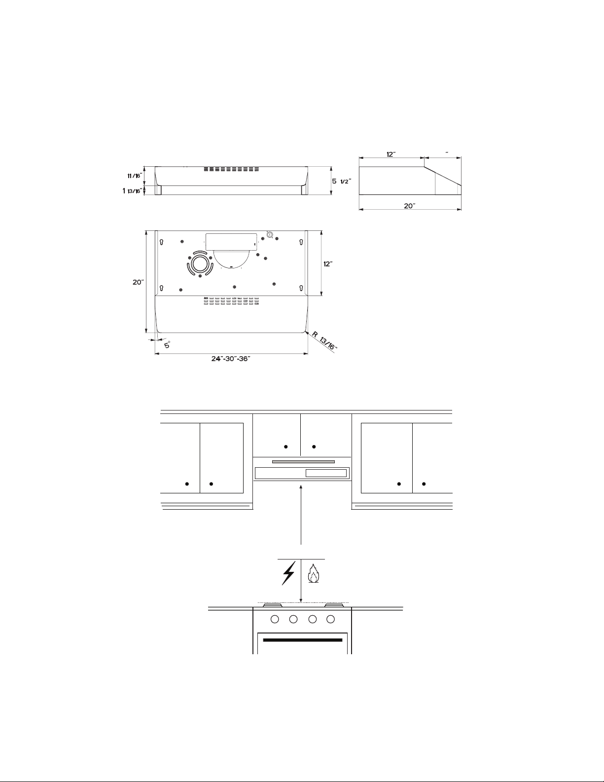
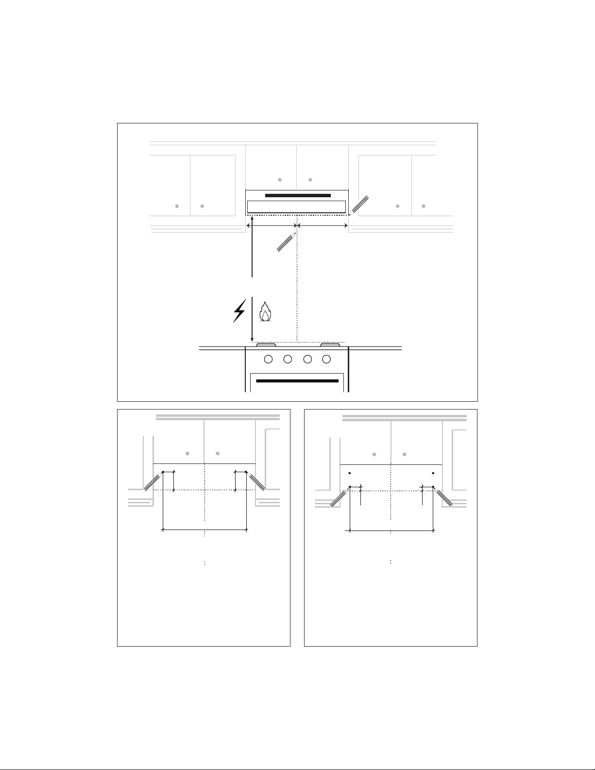
This rangehood requires at least 24" of clearance between the bottom of the rangehood
and the cooking surface or countertop. This hood has been approved by UL at this distance
from the cooktop. The maximum depth of overhead cabinets is 13". Overhead cabinets on both
sides of this unit must be a minimum of 18" above the cooking surface or countertop.
Consult the cooktop or range installation instructions given by the manufacturer before making
any cutouts. MOBILE HOME INSTALLATION The installation of this rangehood must conform
to the Manufactured Home Construction and Safety Standards, Title 24 CFR, Part 3280 (formerly
Federal Standard for Mobile Home Construction and Safety, Title 24, HUD, Part 280). Four wire
power supply must be used and the appliance wiring must be revised. See Electrical Requirements.
• Venting system MUST terminate outside the home.
• DO NOT terminate the ductwork in an attic or other enclosed space.
• DO NOT use 4" laundry-type wall caps.
• Flexible-type ductwork is not recommended.
• DO NOTNARSQTBSSGDkNVNEBNLATRSHNM@MCUDMSHK@SHNM@HQ
q%@HKTQDSNENKKNVUDMSHMFQDPTHQDLDMSRL@XQDRTKSHM@jQD
WARNING
!
Cold Weather installations
M@CCHSHNM@KA@BJCQ@ESC@LODQRGNTKCADHMRS@KKDCSNLHMHLHYDA@BJV@QCBNKC@HQkNV@MC@
nonmetallic thermal break should be installed to minimize conduction of outside temperatures as
part of the vent system. The damper should be on the cold air side of the thermal break. The break
should be as close as possible to where the vent system enters the heated portion of the house.
VENTING REQUIREMENTS
Determine which venting method is best for your application. Ductwork can extend either through the
wall or the roof.
3GDKDMFSGNESGDCTBSVNQJ@MCSGDMTLADQNEDKANVRRGNTKCADJDOSSN@LHMHLTLSNOQNUHCDDEjBHDMS
performance. The size of the ductwork should be uniform. Do not install two elbows together. Use
CTBSS@ODSNRD@K@KKINHMSRHMSGDCTBSVNQJRXRSDL4RDB@TKJHMFSNRD@KDWSDQHNQV@KKNQkNNQNODMHMF
around the cap.
Flexible ductwork is not recommended. Flexible ductwork creates back pressure and air turbulence
that greatly reduces performance.
,@JDRTQDSGDQDHROQNODQBKD@Q@MBDVHSGHMSGDV@KKNQkNNQENQDWG@TRSCTBSADENQDL@JHMFBTSNTSR
Do not cut a joist or stud unless absolutely necessary. If a joist or stud must be cut, then a supporting
frame must be constructed.
WARNING - To Reduce The Risk Of Fire, Use Only Metal Ductwork.
" 43(.-3NQDCTBDQHRJNEkQD@MCSNOQNODQKXDWG@TRS@HQADRTQDSNCTBS@HQNTSRHCDm#N
not vent exhaust air into spaces within walls or ceilings or into attics, crawl spaces, or garages.
3. When cutting or drilling into wall or ceiling, do not damage electrical wiring and
other hidden utilities.
4. Ducted fans must always be vented to the outdoors.
4
ELECTRICAL REQUIREMENTS
A 120 volt, 60 Hz AC-only electrical supply is required on a separate 15 amp fused circuit. A time-delay
fuse or circuit breaker is recommended. The fuse must be sized per local codes in accordance with
SGDDKDBSQHB@KQ@SHMFNESGHRTMHS@RRODBHjDCNMSGDRDQH@KQ@SHMFOK@SDKNB@SDCHMRHCDSGDTMHSMD@QSGDjDKC
wiring compartment.
ELECTRICAL INSTALLATION WITH WIRING BOX
THIS UNIT MUST BE CONNECTED WITH COPPER WIRE ONLY. Wire sizes must conform to the
QDPTHQDLDMSRNESGD-@SHNM@K$KDBSQHB@K"NCD -2(-%/ K@SDRSDCHSHNM@MC@KKKNB@KBNCDR@MC
ordinances. Wire size and connections must conform with the rating of the appliance. Copies of the
standard listed above may be obtained from:
National Fire Protection Association
Batterymarch Park
Quincy, Massachusetts 02269
This appliance should be connected directly to the fused disconnect (or circuit breaker) through
kDWHAKD@QLNQDCNQMNMLDS@KKHBRGD@SGDCBNOODQB@AKD KKNVRNLDRK@BJHMSGDB@AKDRNSGD
@OOKH@MBDB@MADLNUDCHERDQUHBHMFHRDUDQMDBDRR@QX 4++HRSDCŭBNMCTHSBNMMDBSNQLTRS
be provided at each end of the power supply cable (at the appliance and at the junction box).
6GDML@JHMFSGDDKDBSQHB@KBNMMDBSHNMBTS@ŭGNKDHMSGDV@KK GNKDBTSSGQNTFGVNNC
must be sanded until smooth. A hole through metal must have a grommet.
• Electrical ground is required on this rangehood.
• If cold water pipe is interrupted by plastic, nonmetallic gaskets or other materials, DO
NOT use for grounding.
• DO NOT ground to a gas pipe.
• DO NOT have a fuse in the neutral or grounding circuit. A fuse in the neutral or
grounding circuit could result in electrical shock.
q"GDBJVHSG@PT@KHjDCDKDBSQHBH@MHEXNT@QDHMCNTAS@RSNVGDSGDQSGDQ@MFDGNNCHR
properly grounded.
q%@HKTQDSNENKKNVDKDBSQHB@KQDPTHQDLDMSRL@XQDRTKSHM@jQD
WARNING

5
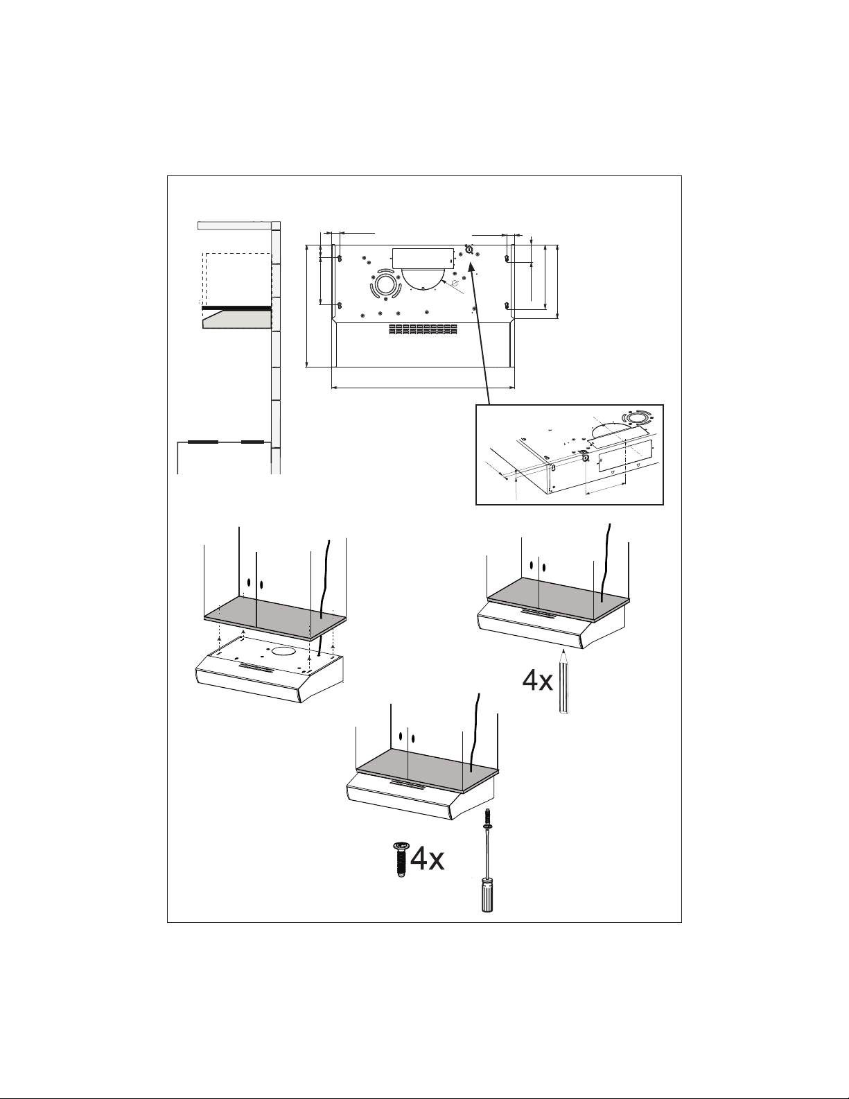
RANGEHOOD DIMENSIONS
Min. 24"
8
3

6
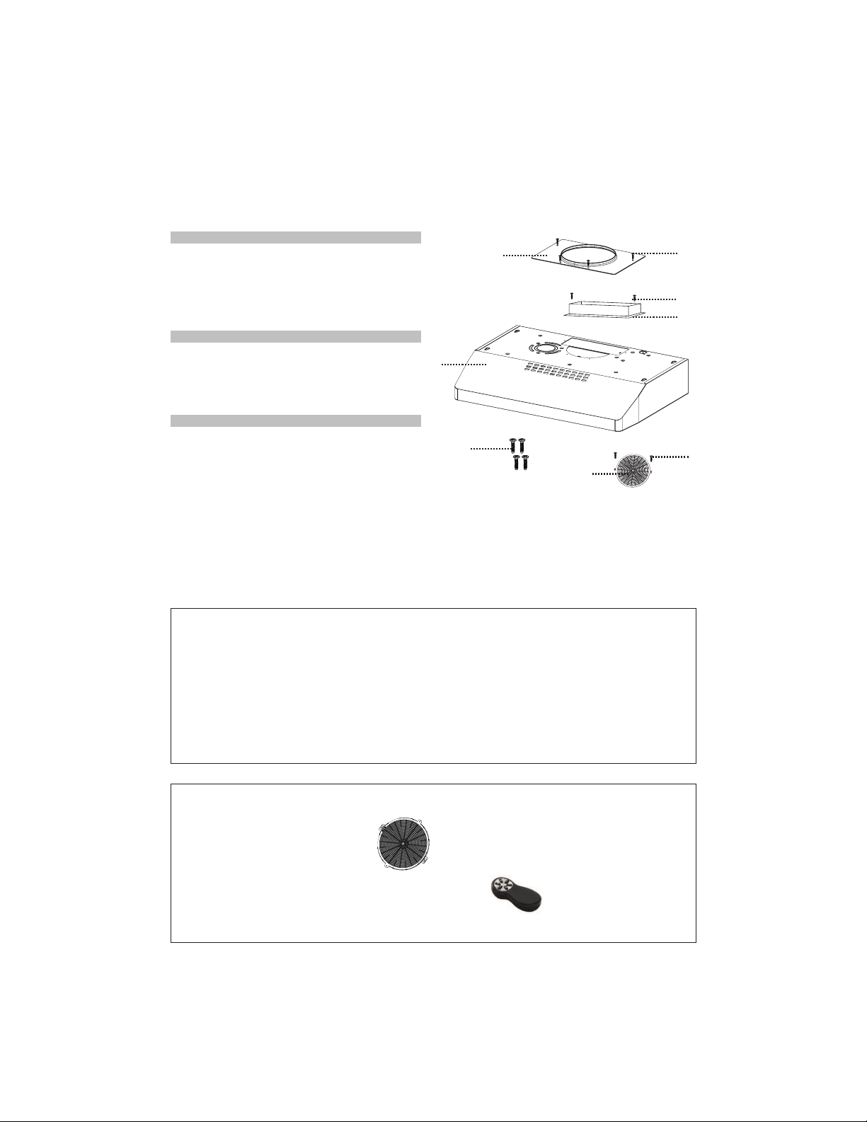
MAIN PARTS
Components
Ref. Qty. Product Components
1 1 Hood Body, complete with:
Controls, Light, Filters, Blower.
10 1 3 1/4" x 10" Damper
10a 1 7" Round Flange
13 1 Grid (Only for Canadian Market)
Ref. Qty. Installation Components
12a 4 Screws 3/16" x 1 15/16" (for
wall mounting)
12c 6 Screws 1/8" x 3/8" (for sup
SOLHGÀDQJHWUDQVLWLRQV
Qty. Documentation
1 Instruction Manual
1
12a
10a
10
12c
12c
12c
13
Available Accessories
Activated Charcoal Filter (FILTER5)
Wireless Remote Control-REMCTRL- (Levante II models only).
Parts needed
5RXQG GDPSHU LI XVLQJ URXQG ÀDQJH
- Drywall plugs or other suitable wall fasteners based on your installation.
- Wire connectors.
For installation that is attached to bottom of wood cabinets with a recessed bottom; 1" x 2" by 12"(approximate
length) wood strips will need to be purchased locally. 12C Wall Mount Screws may work as fasteners for this
W\SH RI LQVWDOO LI QRW WKHQ IRXU ÀDW KHDG ZRRG VFUHZV ZLOO DOVR QHHG WR EH SXUFKDVHG ORFDOO\ WR FRPSOHWH WKLV
type of install.

7
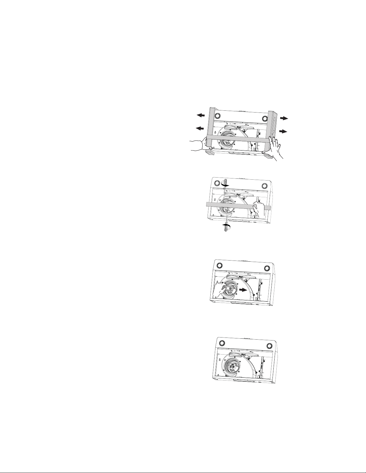
Before Installation Remove These Shipping Materials
Remove the side packaging.
Remove the wood shipping by
unscrew the 4 screws.
Ready for Installation.
Move the block to the right
and pull it off.
8
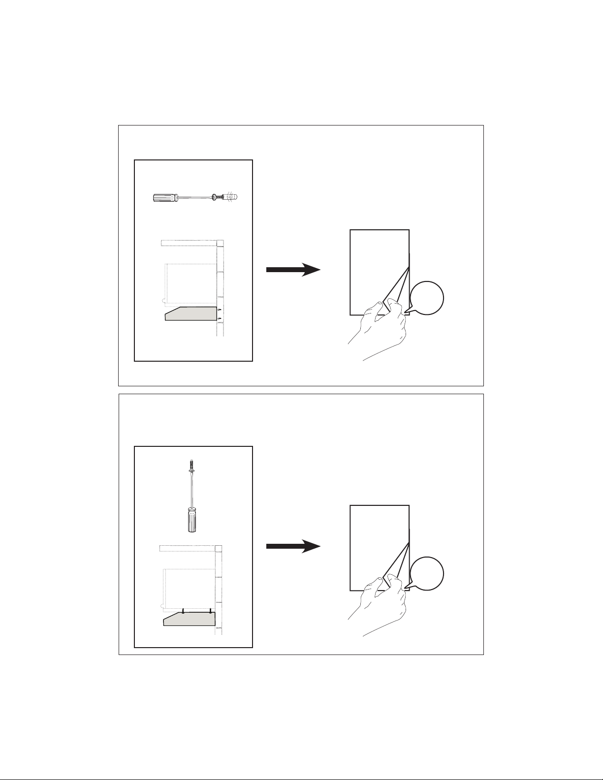
ONLY FOR CANADIAN MARKET
5HPRYH WKH ¿OWHUV RQH DW D WLPH E\
pushing them towards the back of the
group and pulling down at the same
time.
Install the Grid 13 with 2 screws
removed previously as shown in the
picture.
13
5HPRYH WKH VFUHZ DOUHDG\ ¿[HG
9
a
b
c
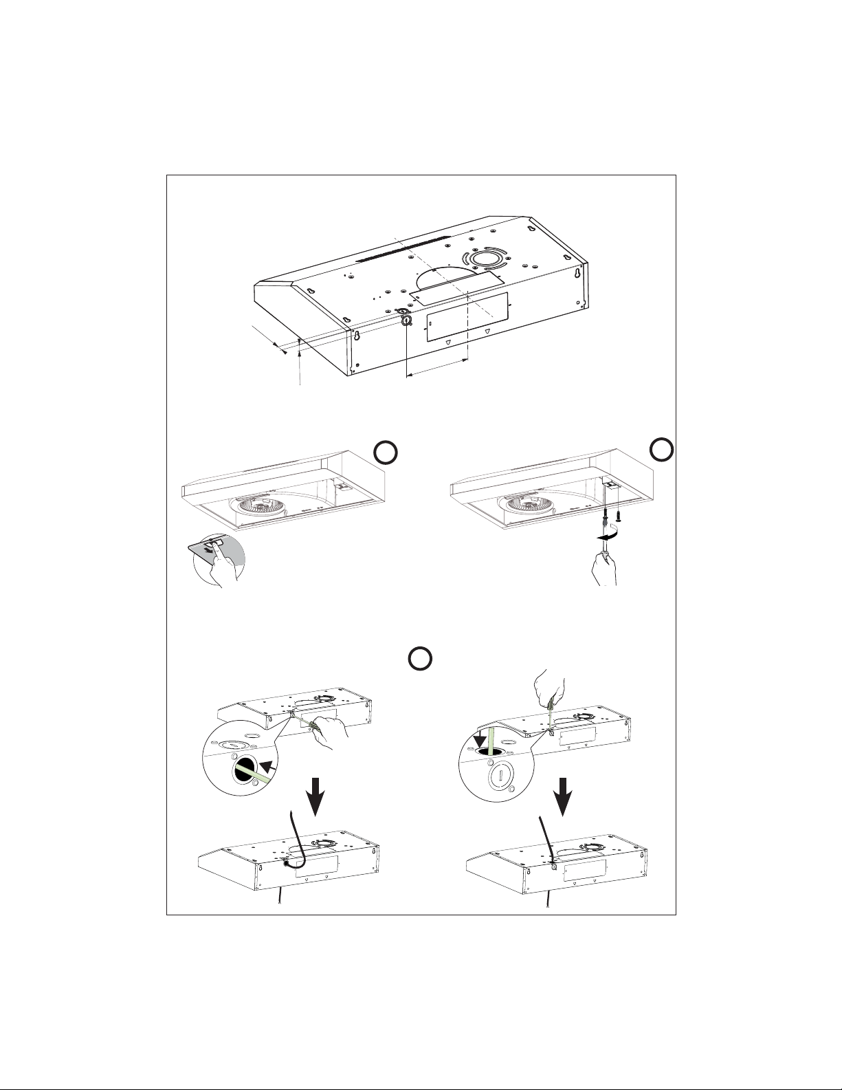
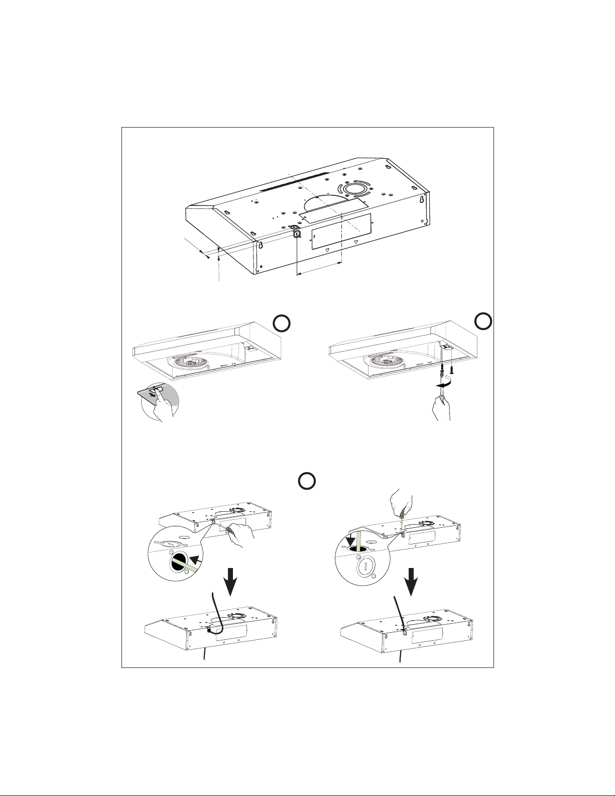
Choose Vertical or Horizontal Electrical Connection Knockout's
5HPRYH WKH ¿OWHUV RQH DW D
time by pushing them towards
the back of the board and
pulling down at the same time.
Remove the wiring box
cover by unscrewing the
2 screws.
Choose the rear hole or top hole for the electric connection and break with a screwdriver or other tool.
During the installation thread Power Supply Cable through this hole.
1D@Q'NKD'NQHYNMS@K 3NO'NKD5DQSHB@K
7" 1/2
13/16"
13/16"
First step before making Vertical or Horizontal Electrical knockout

10
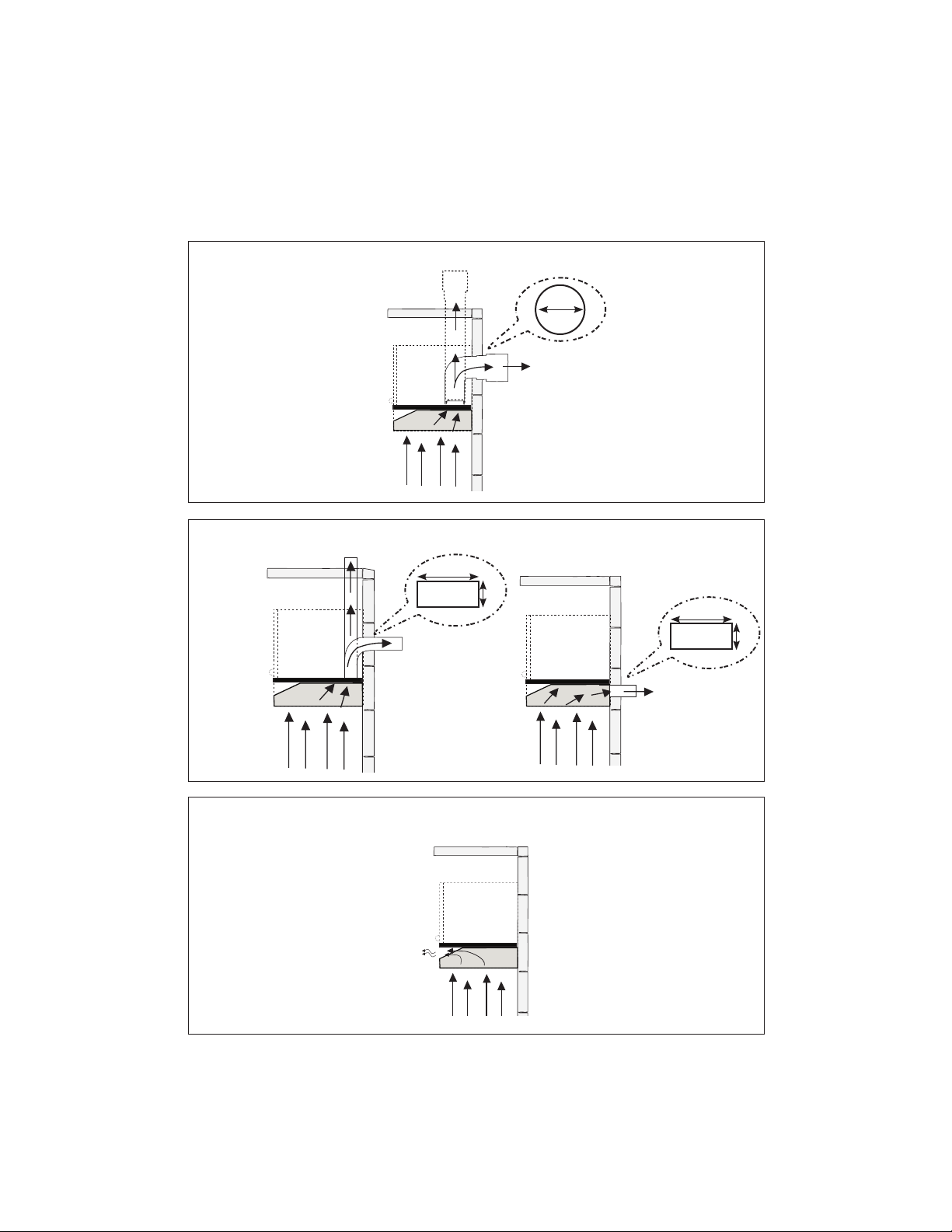
7"
10"
3 1/4"
10"
3 1/4"
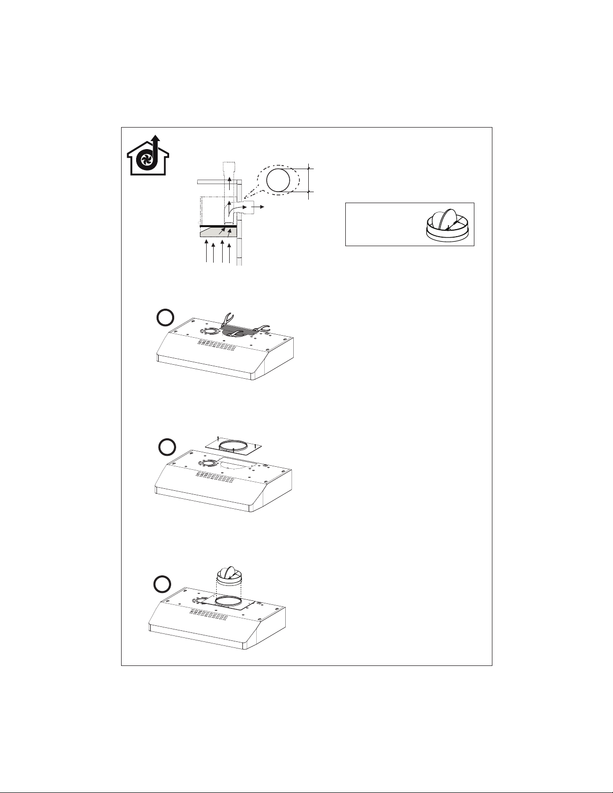
Ducting Methods
Ducted with 7" Round Outlet
Ducted with 3 1/4" x 10" Rectangular Outlet
Non Ducted - Recirculation Option
Rear
Top
Rear
Top
Requires purchase of
Activated Charcoal
Accessory
11
a
b
c
Ducted - 7" Round Outlet
Cut where indicated.
Remove both the angular and semicircle areas
with metal shears.
,QVWDOOWKHLQFOXGHGÀDQJHZLWK)ODQJHWUDQVL-
tion screws 12c
Install 7" Round Damper purchased sepa-
rately.
Rear
Top
7"
Required; 7" Round
Damper Accessory
purchase locally.
Go to page 14
12
a
b
c
a
b
c
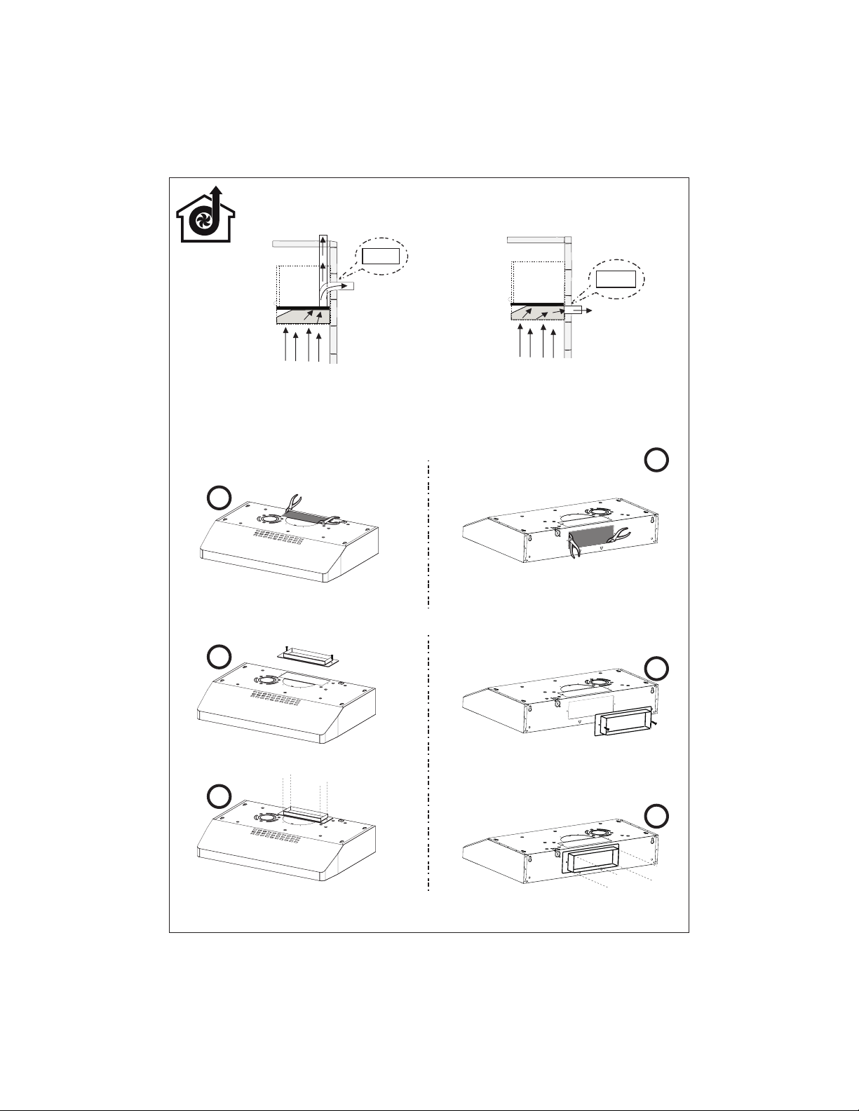
Ducted - 3 1/4" x 10"
Choose the rectangular upper air outlet or rectangular rear air outlet and cut where indicated.
,QVWDOOWKHLQFOXGHGUHFWDQJXODUDLURXWOHWZLWKWZRÀDQJHWUDQVLWLRQVFUHZVF
Rear
Rear
Top
RearTop
3 1/4" x 10"
3 1/4" x 10"
Go to page 14

13
b1
a
b2
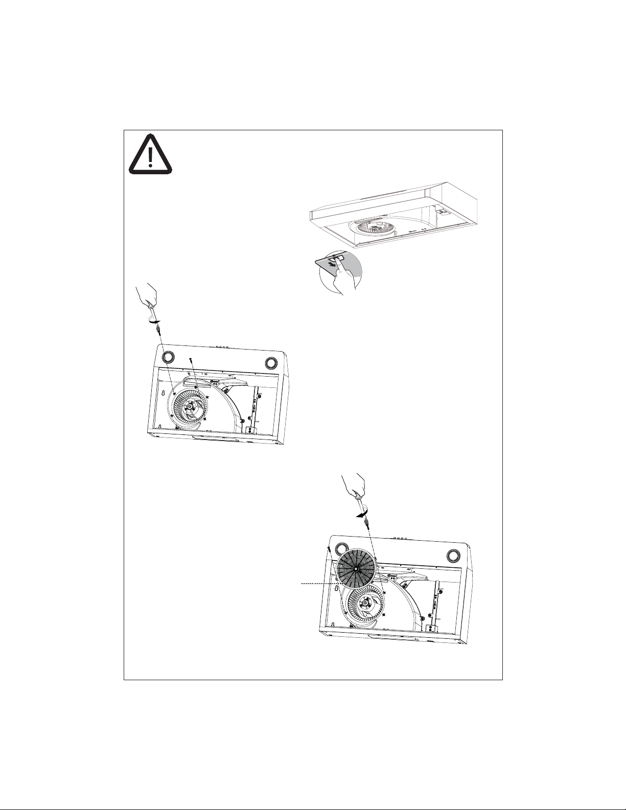
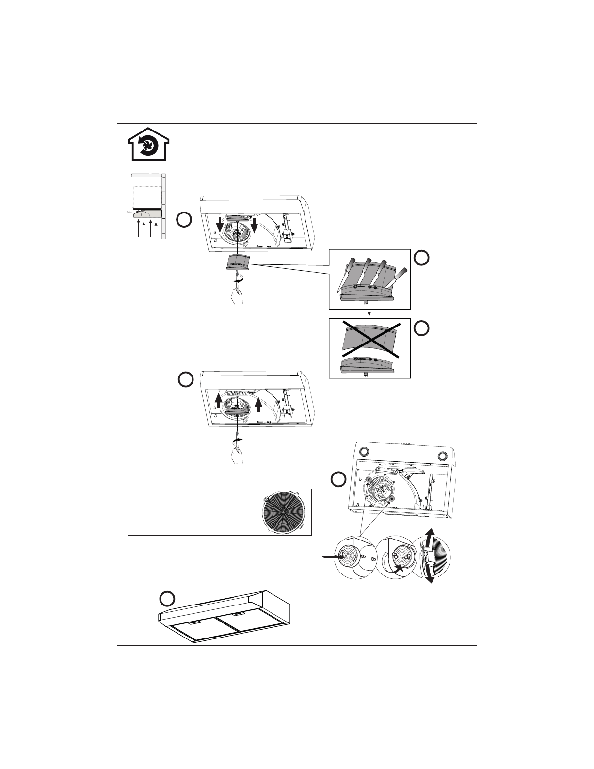
Non Ducted Recirculation Option
Remove the indicated blower cover (do not
discard the screw).
Reinstall the existing Grease Filters after
installing the Activated Charcoal Filter before
operating hood.
5HLQVWDOO WKH PRGL¿HG EORZHU FRYHU ZLWK WKH
same screw.
Cut the
cover
where
indicated in
picture b1.
Discard /
Recycle
lower
pieces of
blower
cover.
Required Activated Charcoal Filter
Accessory - (FILTER5) purchased
separately.
Install the Activated Charcoal Filter purchased separately.
where indicated in the picture.
c
d
b3

14
Installation for Mounting on the Wall
Installation for Mounting to the cabinet
15
17

15
A1
==
Min. 24"
Installation Instruction for mounting on the Wall
Draw a vertical line on the supporting wall as
high as practical, at the center of the area in
which the hood will be installed.
Draw a horizontal line at where the bottom
edge of the hood will be located as indicated
LQWKH¿JXUHWKDWLVD PLQLPXPRI DERYH
cooking surface
4 15/16”
4 15/16”
24” - - > A= 21 3/8”
30” - - > A= 27
3/8”
36” - - > A= 33
3/8”
A
1”
1”
24” - - > A= 21 3/8”
30” - - > A= 27
3/8”
36” - - > A= 33
3/8”
A
A2 A3
Mark the wall where indicated, 4 15/16" above the
horizontal line and at A distance on the left and
right of vertical line.
Mark the wall where indicated, 1" above the hori-
zontal line and at A distance on the left and right
of vertical line.
16
A4
´
;
Drill directly into ø 3/16" holes at all the center points marked.
Insert the purchased wall plugs in the holes.
If fastener locations do not align with the studs, insert the purchased wall plugs in the holes.
A5 A6
In upper holes use two of the supplied screws to
secure the hood body to the wall.
Using two remaining screws anchor the hood in
lower holes as indicated.
17
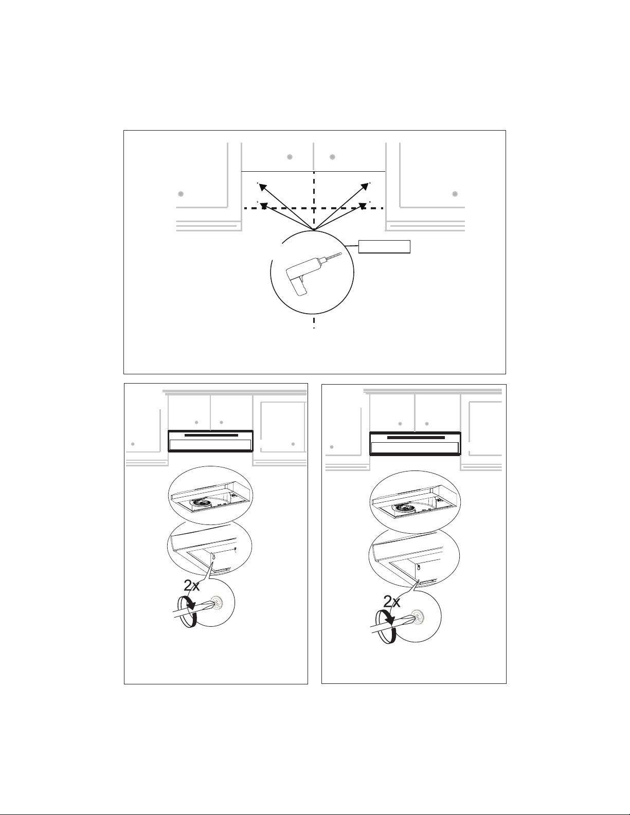
B1
Installation Instruction for Mounting Under to the Cabinet
Mark the
KROHV IRU ¿[LQJ
verifying the
measures with
the diagram.
20"
24"-30"-36"
12"
7"
2" 13/16
10" 1/2
1" 5/16
1" 5/16
7" 11/16 2"
Lift the hood
to the cabinet.
Fix the Hood
Body with 4
screws from
the bottom.
7" 1/2
13/16"
13/16"
18
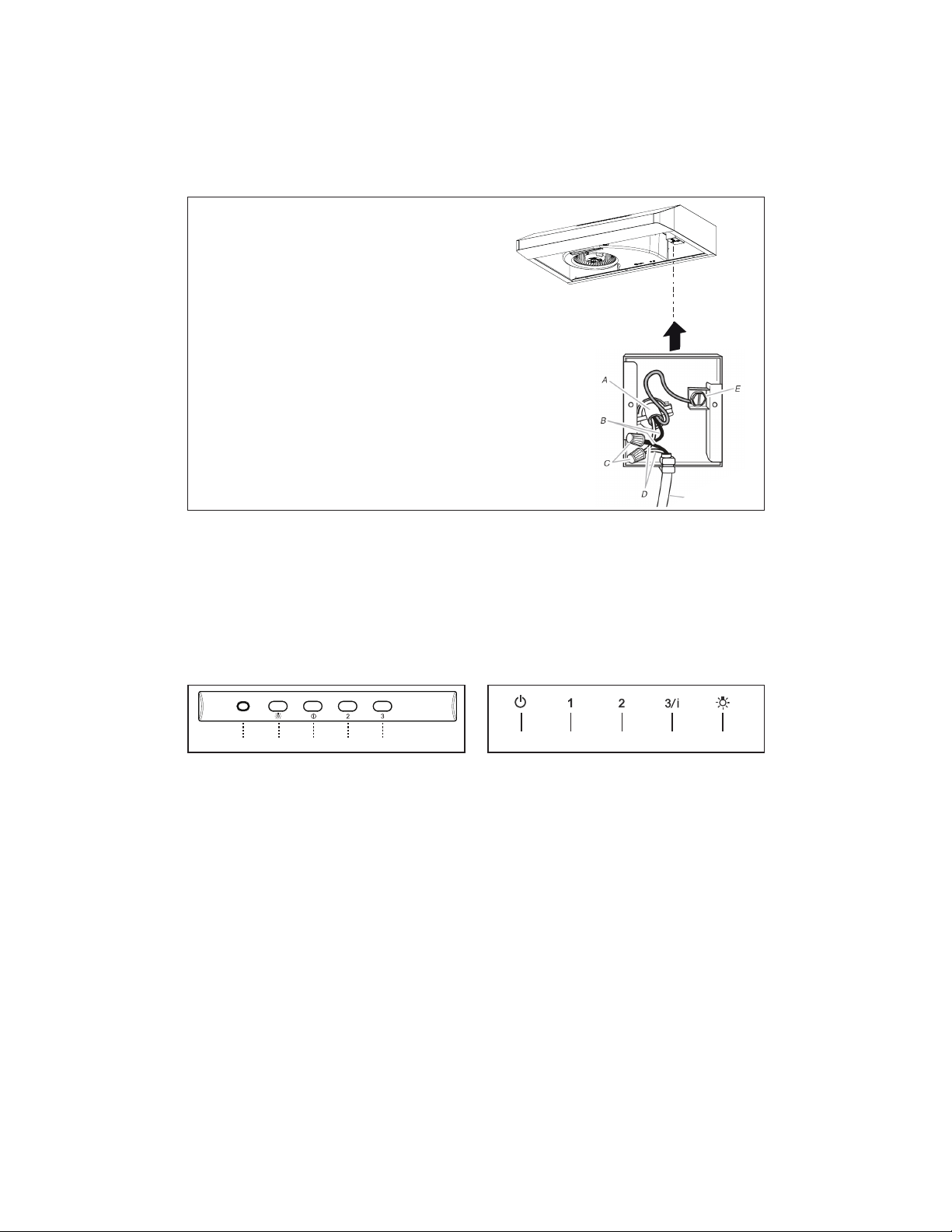
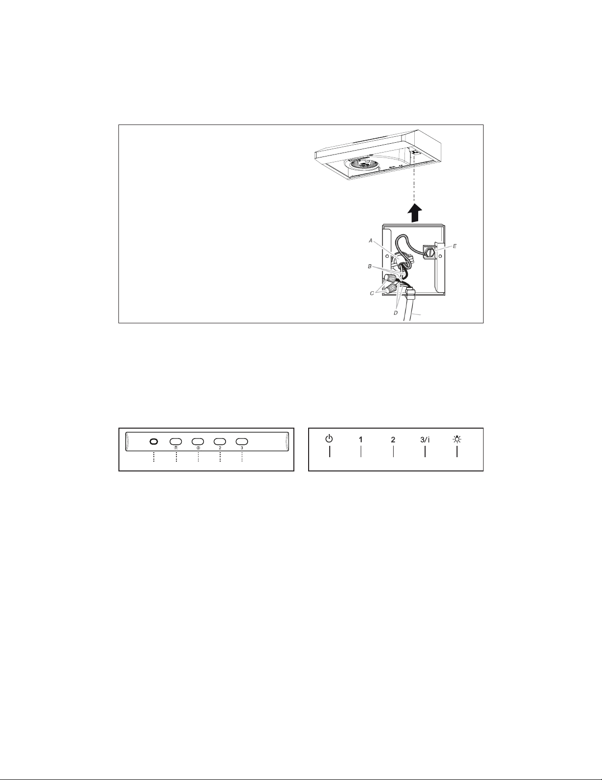
Installation of wiring connection
5HPRYHWKHFRYHUIURPWKH¿HOGZLULQJFRPSDUWPHQW
5HPRYHWKHZLULQJHOHFWULFDONQRFNRXWXVLQJDÀDW
blade screwdriver. Feed the Power Supply Cable
through the electrical knockout.
Connect the Power Supply Cable to the rangehood.
Attach the White lead of the power supply (A) to the
White lead of the rangehood (D) with a twist-on type
wire connector. Attach the Black lead of the power
supply to the Black lead of the rangehood (B) with
a twist-on type wire connector (C). Connect the
Green (E) (Green and Yellow) ground wire under
the Green grounding screw.
5HSODFH WKH ¿HOG ZLULQJ FRPSDUWPHQW FRYHU DQG
WKHJUHDVH¿OWHUV
Hood wiring
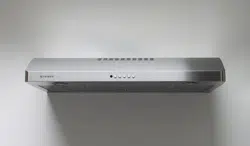
USE AND CARE INFORMATION
G. Indicator Light
L. Lights - On and Off.
V1. Low Speed.
V2. Medium Speed.
V3. Maximum Speed..
T1. Fan Off Button:Turn the blower Off. The fan can be oper-
ated by pressing any of the fan setting buttons.
Hold down this button for 2 seconds to activate delayed
off function which will keep the fan On for 15 minutes and
automatically shut Off.
T2. Fan Settings Buttons: Low Speed.
T3. Fan Settings Buttons: Medium Speed.
T4. Fan Settings Buttons: High Speed.
Hold down the button for 2 seconds to activate the INTEN-
SIVE SPEED, which is timed to run for 10 minutes. At the
end of this time it will automatically return to the speed set
before.Suitable to deal with maximum levels of cooking
fumes.
L. Light Button: On/Dim/Off switch for the halogen lights.
Press the LIGHT button to turn the light on, again to set
the lights to dimmer, and again to turn off.
LT1 T2 T3 T4
L V1 V2 V3G
For Best Results
6WDUWWKHUDQJHKRRGVHYHUDOPLQXWHVEHIRUHFRRNLQJWRGHYHORSSURSHUDLUÀRZ$OORZWKHUDQJHKRRGWRRSHU-
ate for several minutes after cooking is complete to clear all smoke and odors from the kitchen.
"NMSQNK+DU@MSD( "NMSQNK+DU@MSD((
19
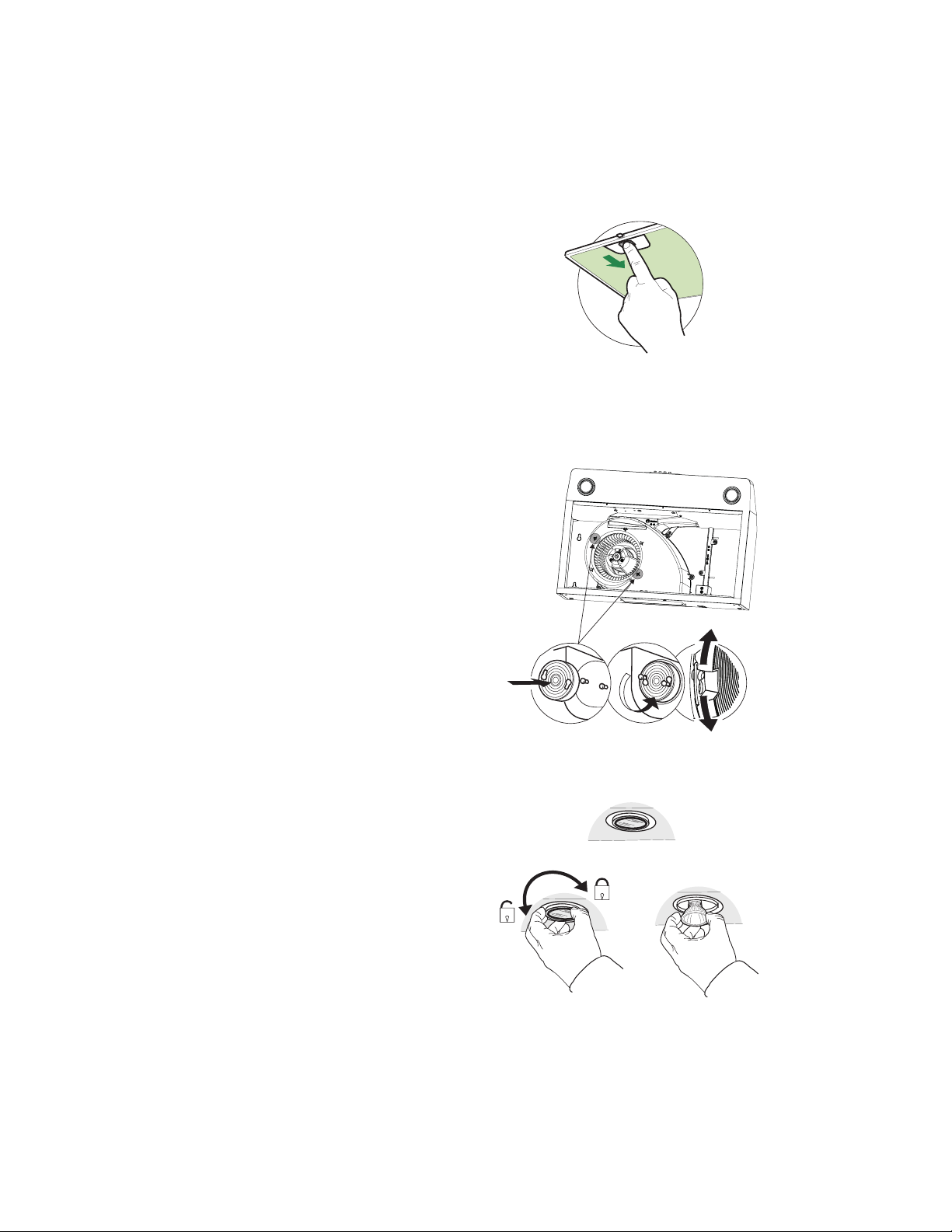
"KD@MHMFLDS@KFQD@RDkKSDQR
7KHPHWDOJUHDVH¿OWHUVFDQEHFOHDQHGLQKRWGHWHUJHQW
solution or washed in the dishwasher. They should be
cleaned every 2 months use, or more frequently if use
is particularly heavy.
• 5HPRYHWKH¿OWHUSXVKLQJWKHOHYHUWRZDUGVWKHEDFN
of the unit and at the same time pulling downward.
• :DVK WKH¿OWHUZLWKRXW EHQGLQJ LW OHDYH LW WRGU\
WKRURXJKO\EHIRUHUHSODFLQJLIWKHVXUIDFHRIWKH¿OWHU
changes color over time, this will have absolutely no
HIIHFWRQLWVHI¿FLHQF\
• Replace, taking care to ensure that the handle
faces forward.
• &OHDQLQJLQGLVKZDVKHUPD\GXOOWKH¿QLVKRI
WKHPHWDOJUHDVH¿OWHU
Replacing Activated Charcoal Filter
The Activated Charcoal Filters are not washable
and cannot be regenerated, and must be
replaced approximately every 4 months of
operation, or more frequently with heavy usage.
5HPRYHWKHJUHDVH¿OWHUV
5HPRYHWKHVDWXUDWHGFDUERQ¿OWHUE\UHOHDV-
LQJWKH¿[LQJKRRNV
)LWWKHQHZ¿OWHUE\KRRNLQJLWLQWRLWVVHDWLQJ
5HSODFHWKHJUHDVH¿OWHUV
Replacing the bulbs
35 W halogen. Type GU10 bulb
• Remove the bulb (See the picture).
• Replace the bulb with a new one of the same
type, making sure that you insert the two pins
properly into the housings on the lamp holder
and twist to lock back in place.
• Remove grease filters.
• Screw the Frame into place
12f, re-
20
+U
+U
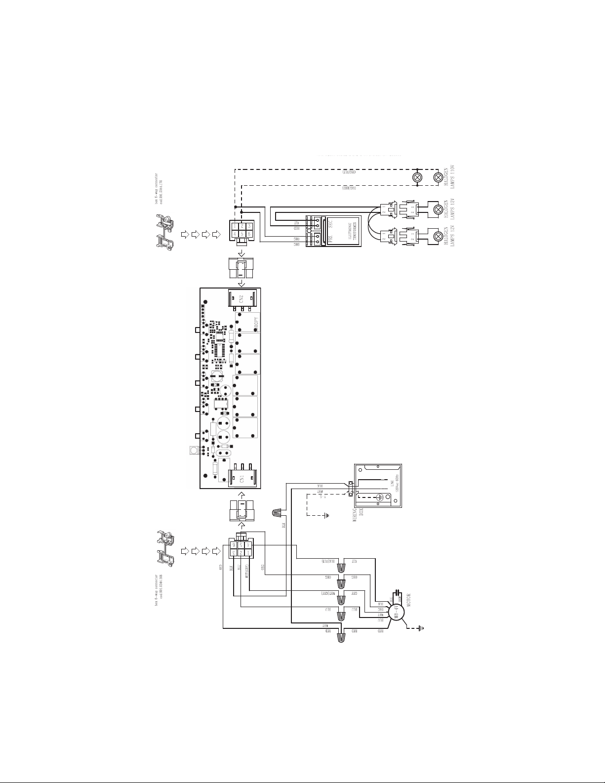
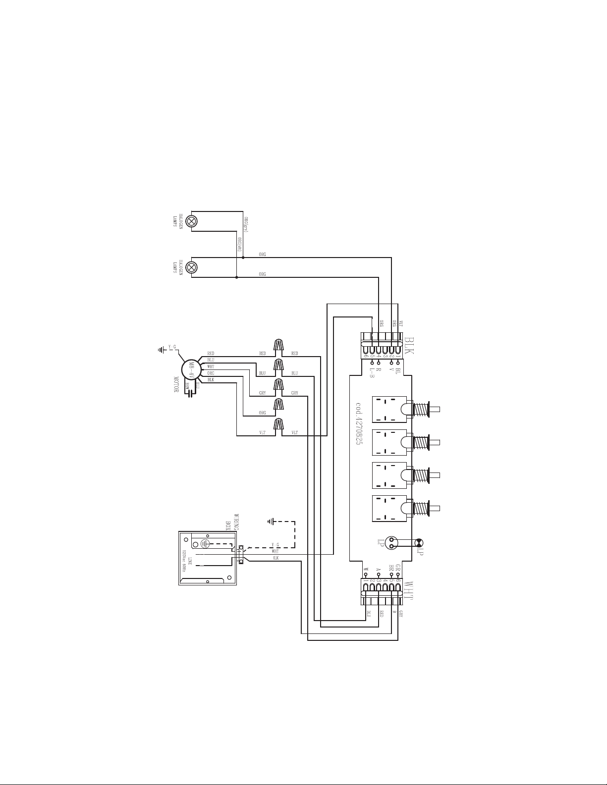
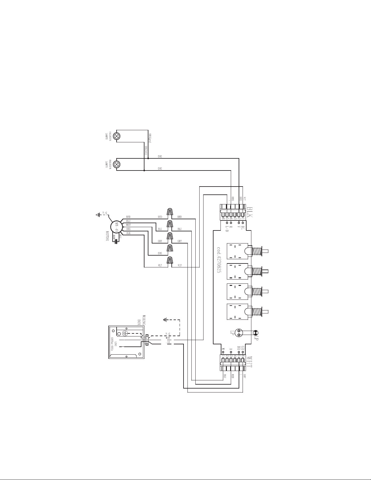
Wiring Diagram
LEVT30SS400-B LEVT36SS400-B
21
+B +B
Wiring Diagram
LEVA24SS300-B LEVA24WH300-B LEVA24BK300-B
LEVA30SS300-B LEVA30WH300-B LEVA30BK300-B
LEVA36SS300-B LEVA36WH300-B LEVA30BK300-B

22
January 4, 2016
FABER CONSUMER WARRANTY & SERVICE
All Faber products are warranted against any defect in materials or workmanship for the original purchaser
for a period of 1 year from the date of original purchase (requires proof of purchase). This warranty covers
labor and replacement parts. Faber, at its option, may repair or replace the product or components
necessary to restore the product to good working condition. To obtain warranty service, contact the dealer
from whom you purchased the range hood, or the local Faber distributor. If you cannot identify a local Faber
distributor, contact us at (508) 358-5353 for the name of a distributor in your area.
The following is not covered by Faber's warranty:
1. Service calls to correct the installation of your range hood, to instruct you how to use your range hood, to
replace or repair house fuses or to correct house wiring or plumbing.
2. Service calls to repair or replace range hood light bulbs, fuses or filters. Those consumable parts are
excluded from warranty coverage.
3. Repairs when your range hood is used for other than normal, single-family household use.
4. Damage resulting from accident, alteration, misuse, abuse, fire, flood, acts of God, improper installation,
installation not in accordance with electrical or plumbing codes or Faber documentation, or use of products
not approved by Faber.
5. Replacement parts or repair labor costs for units operated outside the United States or Canada, including
any non-UL or C-UL approved Faber range hoods.
6. Repairs to the hood resulting from unauthorized modifications made to the range hood.
7. Expenses for travel and transportation for product service in remote locations and pickup and delivery
charges. Faber range hoods should be serviced in the home.
THIS WARRANTY DOES NOT ALLOW RECOVERY OF INCIDENTAL OR CONSEQUENTIAL DAMAGES, INCLUDING, WITHOUT
LIMITATION, DIRECT, INDIRECT, INCIDENTAL, SPECIAL OR CONSEQUENTIAL DAMAGES, PERSONAL INJURY/WRONGFUL
DEATH OR LOST PROFITS FABER WARRANTY IS LIMITED TO THE ABOVE CONDITIONS AND TO THE WARRANTY PERIOD
SPECIFIED HEREIN AND IS EXCLUSIVE. EXCEPT AS EXPRESSLY SPECIFIED IN THIS AGREEMENT, FABER DISCLAIMS ALL
EXPRESS OR IMPLIED CONDITIONS, REPRESENTATIONS, AND WARRANTIES INCLUDING, WITHOUT LIMITATION, ANY
IMPLIED WARRANTIES OF MERCHANTABILITY OR FITNESS FOR A PARTICULAR PURPOSE
.
This warranty gives you specific legal rights that may vary from state to state.
Model#: ______________________________ Serial #: _____________________________

23
VEUILLEZ LIRE ET CONSERVER LA PRÉSENTE NOTICE AVANT DE
COMMENCER L'INSTALLATION DE LA HOTTE DE CUISINE
5$13(22$,$-3/.411Í#4(1$+$1(204$#f4-%$4#$&1 (22$241+ 3 !+$#$"4(22.-Ů
a) Ne laissez jamais sans surveillance les éléments de la surface de cuisson à température élevée.
Les bouillonnements excessifs peuvent provoquer de la fumée et les débordements de graisse
ODTUDMSRfDMl@LLDQ+fGTHKDCNHSģSQDBG@TEEĢDKDMSDLDMSĒTMDSDLOĢQ@STQDA@RRDNTLNXDMMD
b) Assurez-vous de toujours mettre en marche le ventilateur de la hotte lorsque vous cuisinez à
SDLOĢQ@STQDĢKDUĢDNTOQĢO@QDYTMLDSRl@LAĢODWBQģODR2TYDSSDBDQHRDRITAHKĢATEl@LAĢ
c) Nettoyez régulièrement les ventilateurs d'aspiration. Assurez-vous de ne pas laisser de la graisse
Rf@BBTLTKDQRTQKDUDMSHK@SDTQNTKDkKSQD
C4SHKHRDYSNTINTQRCDRONģKDRDSB@RRDQNKDRCDK@S@HKKD@OOQNOQHĢD4SHKHRDYSNTINTQRCDRTRSDMRHKDR
de cuisine de la taille adaptée à celle de l'élément chauffant.
5$13(22$,$-3Ů/.41/1Í5$-(1+$2!+$2241$2$-" 2#$%$4#$&1 (22$241+
3 !+$#$"4(22.-24(5$9+$21$".,, -# 3(.-224(5 -3$2Ů
a) ÉTOUFFEZ LES FLAMMES à l'aide d'un couvercle hermétique, d'une plaque à biscuits ou d'un
plateau métallique, puis éteignez le brûleur. FAITES ATTENTION AUX BRÛLURES. Si le feu ne
s'éteint pas immédiatement, QUITTEZ LES LIEUX ET APPELEZ LES POMPIERS.
b) NE PRENEZ JAMAIS UNE CASSEROLE EN FLAMME - Vous pourriez vous brûler.
c) N'UTILISEZ JAMAIS DE L'EAU, ni un linge à vaisselle ou un torchon mouillé, pour éteindre le feu.
Cela pourrait provoquer une violente explosion de vapeur.
C4SHKHRDYTMDWSHMBSDTQ4-(04$,$-3RHŮ
5NTRģSDRBDQS@HMPTfHKRf@FHSCfTMDWSHMBSDTQCDBK@RRD !"DSPTDUNTRBNMM@HRRDYAHDMRNM
mode d'emploi.
2. Le feu est de faible intensité et se limite à l'endroit où il a démarré.
3. Les pompiers ont déjà été appelés.
4MDUNHDCDRNQSHDRDSQNTUDCDQQHġQDUNTRODMC@MSPTDUNTRĢSDHFMDYKDRl@LLDR
#e@OQĠRKDFTHCDgŰ*HSBGDM%HQDR@EDSX3HORŰuOTAKHġO@QK@-%/ @TWÍS@SR4MHR
AVERTISSEMENT - POUR RÉDUIRE LE RISQUE D'INCENDIE OU DE CHOC ÉLECTRIQUE, n'utilisez
jamais ce ventilateur en association avec un dispositif de réglage de vitesse à semi-conducteurs.
AVERTISSEMENT - POUR RÉDUIRE LES RISQUES D'INCENDIE, DE CHOC ÉLECTRIQUE OU DE
!+$2241$".1/.1$++$1$2/$"3$9+$2(-2314"3(.-224(5 -3$2Ů
1. Utilisez cet appareil uniquement de la façon prévue par le fabricant.
2. Pour toute question, communiquez avec le fabricant.
3. Avant de procéder à l'entretien ou au nettoyage de l'appareil, coupez l'alimentation au niveau
du panneau électrique et verrouillez-le pour vous assurer que l'électricité n'est pas rétablie ac-
cidentellement.
4. 2fHKMfDRSO@RONRRHAKDCDUDQQNTHKKDQKDCHRONRHSHECfHMSDQQTOSHNMCDKf@KHLDMS@SHNM@EkBGDYCDE@ĞNM
ferme et bien visible un avis de danger, par exemple à l'aide d'une étiquette sur le panneau.
33$-3(.-Ů#DRSHMĢĒTMTR@FDCDUDMSHK@SHNMFĢMĢQ@KDTMHPTDLDMS-fTSHKHRDYO@RBDCHRONRHSHE
pour l'aspiration de vapeurs ou de matériaux dangereux ou explosifs.
AVERTISSEMENT - POUR RÉDUIRE LES RISQUES D'INCENDIE, DE CHOC ÉLECTRIQUE OU DE
!+$2241$".1/.1$++$1$2/$"3$9+$2(-2314"3(.-224(5 -3$2Ů
1. +fHMRS@KK@SHNMDSKDAQ@MBGDLDMSĢKDBSQHPTDCNHUDMSģSQDQĢ@KHRĢRO@QTMSDBGMHBHDMPT@KHkĢDS
conformément à tous les codes et normes en vigueur, incluant ceux concernant la construction
à l'épreuve du feu.
2. kMCDF@Q@MSHQTMDBNLATRSHNMDSTMDĢU@BT@SHNM@CĢPT@SDRCDRF@YO@QKDRBNMCTHSDRCDK@
cheminée des appareils à combustion, une bonne aération est nécessaire pour éviter le refoule-
ment. Respectez les lignes directrices fournies par le fabricant du matériel chauffant, ainsi que
KDRMNQLDRCDRĢBTQHSĢBNLLDBDKKDROTAKHĢDRO@QK@-@SHNM@K%HQD/QNSDBSHNM RRNBH@SHNM-%/
DSK@ LDQHB@M2NBHDSXENQ'D@SHMF1DEQHFDQ@SHNM@MC HQ"NMCHSHNMHMF$MFHMDDQR 2'1 $@TW
États-Unis, ainsi que les codes en vigueur dans votre région.

24
T
.43$.45$1341$# -2+$,41.4+$/+ -"'$1½/1.7(,(3Í#$+ '.33$#.(3Î31$
2"$++Í$
4MDRO@BDKHAQDCf@TLNHMRŮŪDRSQDPTHR entre le bas de la hotte et la surface de cuisson ou
KDBNLOSNHQ"DSSDGNSSD@ġSġGNLNKNFTġDO@QKe4+ĐBDSSDCHRS@MBDCDK@RTQE@BDCDBTHRRNM+@
OQNENMCDTQL@WHL@KDCDR@QLNHQDRRTRODMCTDRDRSCDŰON+DR@QLNHQDRRTRODMCTDRCDBG@PTD
BŃSġCDKe@OO@QDHKCNHUDMSRDSQNTUDQĐ@TLNHMRŰŭCDK@RTQE@BDCDBTHRRNMNTCTBNLOSNHQ
Consultez la notice d'installation de la surface de cuisson ou de la hotte fournie par le fabricant avant
de pratiquer des ouvertures. INSTALLATION DANS UNE MAISON MOBILE L'installation de cette
GNSSDCNHSĢSQDBNMENQLDĐK@/@QSHDCDK@MNQLD,@MTE@BSTQDC'NLD"NMRSQTBSHNM@MC2@EDSX
2S@MC@QCR3HSKD"%1OQġBġCDLLDMSK@O@QSHDCDK@MNQLD%DCDQ@K2S@MC@QCENQ,NAHKD'NLD
"NMRSQTBSHNM@MC2@EDSX3HSKD'4#4MD@KHLDMS@SHNMĐPT@SQDjKRCNHSĢSQDTSHKHRġDDSKDBĒAK@FD
CDKe@OO@QDHKCNHSĢSQDHMRODBSġ"NMRTKSDYK@jBGDSDBGMHPTDġKDBSQHPTD
Installation dans les climats froids
+DRXRSĠLDCDUDMSHK@SHNMCNHSOQġUNHQTMQDFHRSQD@MSHQDENTKDLDMSRTOOKġLDMS@HQDONTQQġCTHQDKDkTWCe@HQ
EQNHCHMUDQRD@HMRHPTeTMDA@QQHĠQDSGDQLHPTDONTQQġCTHQDK@BNMCTBSHNMCDRSDLOġQ@STQDRDWSġQHDTQDR
+DQDFHRSQDCNHSĢSQDHMRS@KKġCTBŃSġ@HQEQNHCO@QQ@OONQSĐK@A@QQHĠQDSGDQLHPTD+@A@QQHĠQDSGDQLHPTD
CNHSĢSQDONRHSHNMMġDKDOKTROQĠRPTDONRRHAKDCDKeDMCQNHSNŔKDRXRSĠLDCDUDMSHK@SHNMOġMĠSQDC@MR
K@O@QSHDBG@TEEġDCDK@L@HRNM
CRITÈRES DE VENTILATION
#ġSDQLHMDYPTDKKDLġSGNCDCDUDMSHK@SHNMDRSLHDTW@C@OSġDĐUNSQD@OOKHB@SHNM+DRBNMCTHSRODTUDMS
passer par le mur ou le toit.
/NTQF@Q@MSHQTMDLDHKKDTQDDEjB@BHSġK@KNMFTDTQCDRBNMCTHSRDSKDMNLAQDCDBNTCDRCNHUDMSĢSQDKD
OKTRKHLHSġRPTDONRRHAKD+DCH@LĠSQDCDRBNMCTHSRCDUQ@HSĢSQDTMHENQLD-eHMRS@KKDYO@RCDTWBNTCDR
DMRDLAKD4SHKHRDYTMQTA@MONTQB@M@KHR@SHNMR@jMCDRBDKKDQSNTRKDRINHMSRCTRXRSĠLDCDBNMCTHSR
4SHKHRDYTMB@KEDTSQ@FDONTQRBDKKDQKDRNTUDQSTQDRC@MRKDLTQDWSġQHDTQNTKDOK@MBGDQ@TSNTQCTBK@ODS
,OQHVWSDVUHFRPPDQGpGXWLOLVHUGHVFRQGXLWVÀH[LEOHV/HVFRQGXLWVÀH[LEOHVSURYRTXHQWXQHFRQWUH
SUHVVLRQHWGHODWXUEXOHQFHTXLGLPLQXHQWJUDQGHPHQWOHI¿FDFLWpGHODSSDUHLO
RRTQDYUNTRPTDKeDRO@BDKHAQDC@MRKDLTQNTKDOK@MBGDQDRSRTEjR@MSONTQKDBNMCTHSCeġU@BT@SHNM
avant de pratiquer les ouvertures. Ne coupez jamais une poutre ou un chevron, sauf si c'est absolu-
LDMSMġBDRR@HQD2eHKRe@UĠQDMġBDRR@HQDCDBNTODQTMDONTSQDNTTMBGDUQNMK@BNMRSQTBSHNMCeTM
renforcement est requise.
$9(57,66(0(173RXUUpGXLUHOHULVTXHGLQFHQGLHXWLOLVH]XQLTXHPHQWGHVFRQGXLWVPpWDOOLTXHV
ATTENTION - Pour réduire le risque d'incendie et pour évacuer adéquatement l'air, assurez-
UNTRCDQ@BBNQCDQKDRBNMCTHSRĒKfDWSĢQHDTQm-DCHEETRDYO@RKf@HQCfĢU@BT@SHNMC@MRCDR
espaces à l'intérieur des murs ou du plafond, ou encore à l'intérieur d'un grenier, d'une galerie
technique ou d'un garage.
3. Lorsque vous faites une ouverture ou percez dans un mur ou le plafond, veillez à ne pas endom-
L@FDQKDRkKRĢKDBSQHPTDRNTCf@TSQDRCHRONRHSHERB@BGĢR
4. +DRUDMSHK@SDTQRB@M@KHRĢRCNHUDMSSNTINTQRģSQDQ@BBNQCĢRĒKfDWSĢQHDTQ
q+DRXRSĠLDCDUDMSHK@SHNM#.(3CġANTBGDQĐKeDWSġQHDTQ
• NE FAITES PASCġANTBGDQKDRBNMCTHSRC@MRTMFQDMHDQNTTM@TSQDDMCQNHSEDQLġ
• N'UTILISEZ PASTMBK@ODSCDRġBGDTRDLTQ@KCDŰŭ
q(KMeDRSO@RQDBNLL@MCġCeTSHKHRDQCDRBNMCTHSRkDWHAKDR
• N'ENTRAVEZ PASKDkTWCDKe@HQCDBNLATRSHNMDSCDUDMSHK@SHNM
• Le non-respect des exigences en matière de ventilation pourrait entraîner un incendie.
AVERTISSEMENT
!
25
FICHE TECHNIQUE ÉLECTRIQUE
4MD@KHLDMS@SHNMCDBNTQ@MS@KSDQM@SHECDUNKSĐ'YDRSQDPTHRDRTQTMBHQBTHSĐETRHAKDCHRSHMBS
CD@LOĠQDR(KDRSQDBNLL@MCġCeHMRS@KKDQTMETRHAKDSDLONQHRġNTTMCHRINMBSDTQ+DETRHAKDCNHS
ĢSQDB@KHAQġBNMENQLġLDMS@TWBNCDRDMUHFTDTQONTQKDRB@Q@BSġQHRSHPTDRMNLHM@KDRġKDBSQHPTDRCD
Ke@OO@QDHKHMCHPTġDRRTQK@OK@PTDRHFM@KġSHPTDRHSTġDĐKeHMSġQHDTQCDKe@OO@QDHKĐOQNWHLHSġCTBNLO@QSH-
LDMSCDRBĒAK@FDRDWSDQMDR
INSTALLATION ÉLECTRIQUE AVEC BOÎTIER DE CÂBLAGES
"$3 // 1$(+#.(3Î31$4-(04$,$-3!1 -"'ͽ+e (#$#$%(+2#$"4(51$+DB@KHAQDCDR
jKRCNHSĢSQDBNMENQLD@TWBQHSĠQDRCDK@CDQMHĠQDġCHSHNMCT-@SHNM@K$KDBSQHB@K"NCDCDKe -2(-%/
DSCDKeDMRDLAKDCDRBNCDRDSQġFKDLDMS@SHNMRDMUHFTDTQ+DB@KHAQDCDRjKRDSKDRBNMMDWHNMR
CNHUDMSĢSQD@C@OSġR@TWB@Q@BSġQHRSHPTDRMNLHM@KDRCDKe@OO@QDHK(KDRSONRRHAKDCDRDOQNBTQDQTM
DWDLOK@HQDCDRMNQLDRHMCHPTġDRBHCDRRTRDMBNLLTMHPT@MS@UDBŰ
National Fire Protection Association
Batterymarch Park
0THMBX,@RR@BGTRDSSRÍS@SR4MHR
"DS@OO@QDHKCDUQ@HSĢSQDAQ@MBGġCHQDBSDLDMS@TRDBSHNMMDTQĐETRHAKDNT@TCHRINMBSDTQO@QTMBĒAKD
kDWHAKDCDBTHUQD@UDBAKHMC@FDNTF@HMDMNMLġS@KKHPTD+@HRRDYTMODTCDIDTC@MRKDBĒAKDONTQ
ODQLDSSQDKDCġOK@BDLDMSCDKe@OO@QDHKRHCDRSQ@U@TWCeDMSQDSHDMRe@UġQ@HDMSMġBDRR@HQDR4MQ@BBNQC
CDBNMCTHSGNLNKNFTġO@QKe4+CDŰŭCNHSĢSQDHMRS@KKġ@TWCDTWDWSQġLHSġRCTBĒAKDCe@KHLDMS@SHNM
(au niveau de l'appareil et de la boîte de liaison).
+NQRCDK@Qġ@KHR@SHNMCTAQ@MBGDLDMSġKDBSQHPTDQġ@KHRDYTMSQNTCDŰŰŭC@MRKDLTQ2eHKRe@FHS
CeTMSQNTC@MRKDANHRHKCNHSĢSQDONMBġONTQKDQDMCQDKHRRD2eHKRe@FHSCeTMSQNTC@MRKDLġS@KTM
O@RRDjKRDRSQDPTHR
q4MDLHRDĐK@SDQQDġKDBSQHPTDDRSQDPTHRDONTQBDSSDGNSSD
q-e43(+(2$9/ 2TMSTX@TCeD@TEQNHCDONTQK@LHRDĐK@SDQQDRHBDKTHBHDRSAQ@MBGġO@QCDR
INHMSRDMOK@RSHPTDO@QCDRQNMCDKKDRMNMLġS@KKHPTDRNTCe@TSQDRL@SġQH@TW
q-e43(+(2$9/ 2TMDBNMCTHSDCDF@YONTQK@LHRDĐK@SDQQD
q-e(-23 ++$9/ 2TMETRHAKDRTQKDBHQBTHSMDTSQDNTKDBHQBTHSCDLHRDĐK@SDQQD+@OQġRDMBD
CeTMETRHAKDC@MRKDBHQBTHSMDTSQDNTCDLHRDĐK@SDQQDODTSDMSQ@ıMDQTMBGNBġKDBSQHPTD
q"NMRTKSDYTMġKDBSQHBHDMPT@KHjġRHUNTRMeĢSDRO@RBDQS@HMCDK@LHRDĐK@SDQQDCDK@GNSSD
q+DMNMQDRODBSCDRDWHFDMBDRCDK@jBGDSDBGMHPTDġKDBSQHPTDONTQQ@HSDMSQ@ıMDQTMHMBDMCHD
AVERTISSEMENT
!
26
DIMENSIONS DE LA HOTTE
Min. 24"
8
3
27
PIÈCES PRINCIPALES
Composants
Réf. Qté Composants du produit
1 1 Bâti de la hotte, avec :
Commandes, Éclairage, Filtres,
Ventilateur.
10 1 Registre 3 1/4 " x 10 "
10a 1 Bride ronde 7 "
13 1 Grille (Canada uniquement)
Réf. Qté Composants d'installation
12a 4 Vis 3/16 " x 1 15/16 " (pour pose
murale)
12c 6 Vis 1/8 " x 3/8 " (pour
UDFFRUGGHWUDQVLWLRQÀDVTXH
fourni)
Qté Documentation
1 Mode d'emploi
1
12a
10a
10
12c
12c
12c
13
Accessoires disponibles
Filtre à charbon actif (FILTER5)
Télécommande-REMCTRL- (Modèles Levante II uniquement).
Pièces requises
- Registre circulaire 7 " si bride ronde 7 " utilisée.
&KHYLOOHV SRXU FORLVRQ VqFKH RX DXWUH V\VWqPH GH ¿[DWLRQ PXUDO HQ IRQFWLRQ GH YRWUH LQVWDOODWLRQ
&RQQHFWHXUV GH ¿OV
6L OLQVWDOODWLRQ SUpYRLW OD ¿[DWLRQ GH ODSSDUHLO DX GHVVRXV GDUPRLUHV HQ ERLV DYHF XQ IRQG HQ UHWUDLW LO IDXW
se procurer sur place des bandes de bois de 1 " x 2 " x 12 " (longueur approximative). Les vis de montage
PXUDO & SHXYHQW VDYpUHU DGpTXDWHV HQ JXLVH GH ¿[DWLRQ SRXU FH W\SH GLQVWDOODWLRQ 'DQV OH FDV FRQWUDLUH
il est également nécessaire de se procurer sur place quatre vis à bois à tête plate.
28
Retirez les matériaux d'emballage suivants avant de procéder à l'installation
Enlevez les emballages
latéraux.
Enlevez le cadre de bois en
dévissant les 4 vis.
Vous êtes prêt à procéder à
l'installation.
Déplacez le bloc vers la droite
et tirez pour l'enlever.

29
13
POUR LE MARCHÉ CANADIEN UNIQUEMENT
5HWLUH] OHV ¿OWUHV XQ j XQ HQ OHV SRXV-
sant simultanément vers l'arrière du
groupe et en les tirant vers le bas.
Retirez les 2 vis déjà posées.
Installez la grille 13 à l'aide de 2 vis
enlevées précédemment, comme dans
l'illustration.
30
a
b
c
7" 1/2
13/16"
13/16"
Choisir l'entrée électrique défonçable verticale ou horizontale
Avant de procéder au défoncement de l'entrée électrique verticale ou
horizontale
5HWLUH] OHV ¿OWUHV XQ j XQ HQ
les poussant simultanément
vers l'arrière du groupe et en
les tirant vers le bas.
Dévissez les 2 vis pour re-
tirer le couvercle du boîtier
de câblage.
&KRLVLVVH] VL YRXV XWLOLVHUH] ORUL¿FH DUULqUH RX ORUL¿FH VXSpULHXU SRXU OH EUDQFKHPHQW pOHFWULTXH HW EULVH]
ORUL¿FH FKRLVL j ODLGH GXQ WRXUQHYLV RX GXQ DXWUH RXWLO
'XUDQW OLQVWDOODWLRQ IDLWHV SDVVHU OH FkEOH GDOLPHQWDWLRQ pOHFWULTXH GDQV FHW RUL¿FH
.QHkBD@QQHġQDGNQHYNMS@K .QHkBDRTOĢQHDTQUDQSHB@K
31
7"
10"
3 1/4"
10"
3 1/4"
"@M@KHR@SHNM@UDBTMBNMCTHSBHQBTK@HQDCDŮŪ
Canalisation avec conduit rectangulaire 3 ŮŪWŮŪ
Arrière
Haut
Méthodes de canalisation
Arrière
Haut
Sans canalisation - Option de recirculation
Exige l'achat de
l'accessoire au
charbon actif

32
a
b
c
7"
Arrière
Haut
UDBB@M@KHR@SHNMBNMCTHSBHQBTK@HQDŮŪ
Requis : registre
circulaire 7 " à se
procurer sur place.
Coupez aux endroits indiqués.
Retirez les zones angulaires et le demi-cercle
à l'aide de cisailles à métaux.
,QVWDOOH]OHÀDVTXHLQFOXVjODLGHGHVYLVF
SRXU UDFFRUG GH WUDQVLWLRQ GX ÀDVTXH
Installez le registre circulaire 7 " acheté
séparément.
Passez à la page 35

33
a
b
c
a
b
c
3 1/4" x 10"
3 1/4" x 10"
Avec canalisation - 3 1/4ŮŪWŮŪ
Arrière
Haut
Arrière
Choisissez la sortie d'air rectangulaire supérieur ou arrière et coupez à l'endroit indiqué.
ArrièreHaut
,QVWDOOH]ODVRUWLHGDLUUHFWDQJXODLUHIRXUQLHjODLGHGHGHX[YLVSRXUUDFFRUGGHWUDQVLWLRQGXÀDVTXHF
Passez à la page 35
34
b1
a
b2
c
d
b3
Option de recirculation sans canalisation
Retirez le couvercle du ventilateur indiqué
(conservez la vis).
Coupez le
couvercle à
l'endroit in-
diqué dans
l'illustration
b1.
Jetez/
Recyclez
les pièces
inférieures
du cou-
vercle du
ventilateur.
5HPHWWH]OHFRXYHUFOHGXYHQWLODWHXUPRGL¿p
en place à l'aide de la même vis.
Accessoire au charbon actif requis - (FIL-
TRE5) acheté séparément.
Avant d'utiliser la hotte, remettez en place le
¿OWUH j JUDLVVH DSUqV DYRLU LQVWDOOp OH ¿OWUH j
charbon actif.
,QVWDOOH]OH¿OWUHDXFKDUERQDFWLIDFKHWpVpSDUpPHQWjOHQGURLW
indiqué dans l'illustration.
35
15
17
Installation pour montage mural
Installation pour montage à l'armoire
36
A1
==
Min. 24"
4 15/16”
4 15/16”
24” - - > A= 21 3/8”
30” - - > A= 27
3/8”
36” - - > A= 33
3/8”
A
1”
1”
24” - - > A= 21 3/8”
30” - - > A= 27
3/8”
36” - - > A= 33
3/8”
A
A2
A3
Instructions pour l'installation mural
Tracez une ligne verticale sur le mur d'appui le plus
haut que possible, au centre de l'emplacement
où la hotte sera installée.
Tracez une ligne horizontale à l'endroit correspon-
dant au bas de la hotte comme représenté dans
l'illustration. Cet emplacement doit se trouver à au
moins 24 " de la surface de cuisson.
Tracez un repère sur le mur à l'endroit indiqué, 4 15/16 "
au-dessus de la ligne horizontale et à la distance A à
droite et à gauche de la ligne verticale.
Tracez un repère sur le mur à l'endroit indiqué, 1 "
au-dessus de la ligne horizontale et à la distance A à
droite et à gauche de la ligne verticale.

37
A4
´
;
A5 A6
Percez des trous de ø 3/16 " directement au centre des repères.
Insérez les chevilles achetées dans les trous.
6LOHPSODFHPHQWGHV¿[DWLRQVQHVWSDVDOLJQpDYHFOHVFKHYURQVLQVpUH]OHVFKHYLOOHVDFKHWpHVGDQVOHVWURXV
Dans les trous supérieurs, utilisez deux des vis
IRXUQLHVSRXU ¿[HUOHEkWLGHODKRWWHDXPXU
Utilisez les deux vis restantes dans les trous infé-
rieurs pour ancrer la hotte au mur.

38
B1
20"
24"-30"-36"
12"
7"
2" 13/16
10" 1/2
1" 5/16
1" 5/16
7" 11/16 2"
7" 1/2
13/16"
13/16"
Instructions pour l'installation sous une armoire
Tracez les
repères pour
l'installation
HQ YpUL¿DQW
les mesures
à l'aide du
diagramme.
Soulevez la
hotte jusqu'à
l'armoire.
Fixez le bâti
de la hotte
par le des-
sous à l'aide
des 4 vis.
39
LT1 T2 T3 T4
L V1 V2 V3G
Câblage de la hotte
Réalisation des branchements
Retirez le couvercle du compartiment des câblages
externes. Défoncez l'entrée électrique à l'aide d'un
tournevis plat. Faites passer le câble d'alimentation
dans l'entrée électrique défoncée.
Branchez le câble d'alimentation à la hotte. Bran-
FKH]OH¿OEODQFGHODOLPHQWDWLRQADX¿OEODQF
de la hotte (D) à l'aide d'un connecteur verrouillé
SDU URWDWLRQ %UDQFKH] OH ¿O QRLU ODOLPHQWDWLRQ
DX¿OQRLUGHODKRWWHB) à l'aide d'un connecteur
verrouillé par rotation (C). Branchez le câble vert
(E) (vert et jaune) de mise à la terre sous la vis
de mise à la terre verte.
Remettez le couvercle du compartiment des
FkEODJHVH[WHUQHVHWOHV¿OWUHVjJUDLVVHHQSODFH
INFORMATIONS POUR L'UTILISATION ET L'ENTRETIEN
Pour de meilleurs résultats
$FWLYH]ODKRWWHTXHOTXHVPLQXWHVDYDQWGHFRPPHQFHUjFXLVLQHUSRXUFUpHUXQÀX[GDLUDGpTXDW/DLV-
VH]ODKRWWHIRQFWLRQQHUTXHOTXHVPLQXWHVDSUqVDYRLU¿QLGHFXLVLQHUSRXUDEVRUEHUWRXWHODIXPpHHWOHV
odeurs de la cuisine.
"NLL@MCDR+DU@MSD( "NLL@MCDR+DU@MSD((
G. Témoin
L. Éclairage - Marche et Arrêt.
V1. Vitesse réduite.
V2. Vitesse moyenne.
V3. Vitesse maximale.
T1. Désactivation du ventilateur : éteint le ventilateur. Le ventilateur
peut être allumé en appuyant sur l'un ou l'autre des boutons
de réglage.
Tenez ce bouton enfoncé pendant 2 secondes pour activer la
fonction de désactivation retardée, qui éteindra automatique-
ment le ventilateur après 15 minutes de marche.
T2. Boutons de réglage du ventilateur : vitesse réduite.
T3. Boutons de réglage du ventilateur : vitesse moyenne.
T4. Boutons de réglage du ventilateur : vitesse élevée.
Tenez le bouton enfoncé pendant environ 2 secondes pour
activer la VITESSE INTENSIVE, pour une durée de 10 min-
utes. Après ce délai, la vitesse retournera automatiquement
à la vitesse sélectionnée précédemment. Utile pour contrer
les émanations maximales de cuisson.
L. Bouton pour l'éclairage : Commutateur Marche/Intensité vari-
able/Arrêt pour l'éclairage halogène. Appuyez sur le bouton
LIGHT pour mettre l'éclairage en marche, de nouveau pour
varier l'intensité et une nouvelle fois pour éteindre.

40
• Remove grease filters.
• Screw the Frame into place
12f, re-
-DSSNX@FDCDRkKSQDRĒFQ@HRRDLĢS@KKHPTDR
/HV¿OWUHVjJUDLVVHPpWDOOLTXHVSHXYHQWrWUHODYpV
dans une solution d'eau chaude savonneuse ou
dans le lave-vaisselle. Ils devraient être nettoyés tous
les 2 mois d'utilisation, ou plus fréquemment en cas
d'utilisation particulièrement intensive.
• 5HWLUH]OH¿OWUHHQSRXVVDQWVLPXOWDQpPHQWOHOHYLHU
vers l'arrière de l'appareil et en le tirant vers le bas.
• /DYH]OH¿OWUHVDQVOHSOLHU/DLVVH]OHVpFKHUFRP-
plètement avant de le réinstaller (un changement
GHODFRXOHXUjODVXUIDFHGX¿OWUHDX¿OGXWHPSV
QDDXFXQLPSDFWVXUVRQHI¿FDFLWp
• Remettez-le en place, en vous assurant que la
poignée se trouve vers l'avant.
• /H ODYHYDLVVHOOH SRXUUDLW WHUQLU OH ¿QL GX ¿OWUH j
graisse métallique.
1DLOK@BDLDMSCTkKSQDĒBG@QANM@BSHE
/HV¿OWUHVjFKDUERQDFWLIQHVRQWSDVODYDEOHVHWQH
peuvent être régénérés. Ils doivent être remplacés
environ tous les 4 mois d'utilisation, ou plus souvent
en cas d'utilisation intensive.
5HWLUH]OHV¿OWUHVjJUDLVVH
5HWLUH]OH¿OWUHjFKDUERQVDWXUpHQGpWDFKDQWOHV
FURFKHWVGH¿[DWLRQ
3RVH]OHQRXYHDX¿OWUHHQOLQVWDOODQWjVRQHPSODFH-
ment.
5HSODFH]OHV¿OWUHVjJUDLVVH
Remplacement des ampoules
Halogènes 35 W. Ampoules de type GU10
• Retirez l'ampoule (consultez l'illustration).
• Remplacez l'ampoule avec une autre du même
type, en vous assurant d'insérer correctement les
deux connecteurs dans leur logement, puis tournez
pour la verrouiller en place.

41
+U
+U
Schéma de câblage
LEVT30SS400-B LEVT36SS400-B
42
+B +B
Schéma de câblage
LEVA24SS300-B LEVA24WH300-B LEVA24BK300-B
LEVA30SS300-B LEVA30WH300-B LEVA30BK300-B
LEVA36SS300-B LEVA36WH300-B LEVA30BK300-B
43
4 janvier 2016
GARANTIE LIMITÉE ET SERVICE FABER
Tous les produits Faber font l'objet d'une garantie contre les défauts de matériel et de main-
d'œuvre,accordée à l'acheteur original pour une période d'un (1) an à compter de la date d'achat initiale
(preuve d'achat requise). Cette garantie couvre les frais de main-d'œuvre et les pièces de rechange. À sa
discrétion, Faber peut réparer ou remplacer le produit ou les composants nécessaires à remettre le produit
en bon état de marche. Pour bénéficier de services prévus par la garantie, veuillez communiquer avec le
détaillant auprès duquel vous avez acheté la hotte de cuisine, ou encore avec le distributeur Faber de votre
région. Si vous n'êtes pas en mesure de localiser un distributeur Faber dans votre région, veuillez
communiquer avec nous au 508-358-5353 pour connaître le nom d'un distributeur à proximité.
Les éléments suivants ne sont pas visés par la garantie Faber :
1. Les appels au service de réparation visant à corriger l'installation de la hotte de cuisine, à recevoir des
instructions sur l'utilisation de la hotte de cuisine, le remplacement ou la réparation des fusibles du domicile
ou la correction des câblages ou de la plomberie du domicile.
2. Les appels au service de réparation visant à réparer ou remplacer les ampoules électriques de hotte, les
fusibles ou les filtres. Ces pièces consommables ne sont pas couvertes par la garantie.
3. Les réparations si votre hotte de cuisine est employée à des fins autres que celles prévues, soit l'utilisation
résidentielle normale pour une famille.
4. Les dommages découlant d'un accident, d'une modification, de l'utilisation incorrecte ou abusive, d'un
incendie, d'une inondation, d'un cas de force majeure, d'une installation inadéquate, d'une installation non
conforme aux codes en matière d'électricité ou de plomberie ou à la documentation fournie par Faber, ou
encore d'une utilisation du produit non approuvée par Faber.
5. Les frais de main-d'œuvre ou de remplacement des pièces pour les appareils utilisés à l'extérieur des
États-Unis ou du Canada, y compris toutes les hottes de cuisine Faber non-UL ou C-UL homologuées.
6. Les réparations à la hotte découlant de modifications non autorisées apportées à la hotte de cuisine.
7. Les frais encourus pour les déplacements et le transport de produits en région éloignée et les frais de
cueillette et livraison. La réparation des hottes de cuisine Faber doit être réalisée à domicile.
LA PRÉSENTE GARANTIE NE PRÉVOIT AUCUNE FORME DE DÉDOMMAGEMENT EN CAS DE DOMMAGES ACCESSOIRES OU
CONSÉCUTIFS, Y COMPRIS, SANS TOUTEFOIS S'Y LIMITER, LES DOMMAGES DIRECTS, INDIRECTS, ACCESSOIRES,
PARTICULIERS OU CONSÉCUTIFS, LES LÉSIONS CORPORELLES/MORTELLES OU LA PERTE DE PROFITS. LA GARANTIE
OFFERTE PAR FABER EST LIMITÉE AUX CONDITIONS ÉNONCÉES CI-DESSUS ET À LA PÉRIODE DE GARANTIE INDIQUÉE
DANS LES PRÉSENTES ET EST EXCLUSIVE. SAUF DISPOSITIONS EXPRESSES CONTRAIRES DANS LE PRÉSENT ACCORD,
FABER DÉCLINE TOUTE CONDITION, REPRÉSENTATION OU GARANTIE EXPLICITE OU IMPLICITE, Y COMPRIS, SANS
TOUTEFOIS S'Y LIMITER, TOUTE GARANTIE IMPLICITE DE QUALITÉ MARCHANDE OU D'ADAPTATION À UN USAGE
PARTICULIER
.
Les droits qui vous sont conférés en vertu de la présente garantie peuvent varier d'une province ou d'un État
à l'autre.
N
o
de modèle : ______________________________ N
o
de série : _____________________________

991.0379.950_03 - 160115