Loading ...
Loading ...
Loading ...
INSTALLING CLUTCH/IDLER ASSEMBLY
ThissectioncoverstheinstallationoftheClutch/Idler
assembly to tractors with attachment clutches that are
either rod operated (p. 9), cable operated (p. 10) or
electric (p. 12). Use the appropriate instructions for
your tractor.
MANUAL ROD OPERATED ATTACHMENT CLUTCH
• Move the attachment clutch lever on the dash
panel to the disengaged (down) position.
• Screw the trunnion onto the end of the snow
thrower engagement rod as shown in figure 11.
• Locate the clutch arm (where the mower clutch rod
was connected) underneath the right hand side the
tractor, just to the inside of the suspension arm. If
there is an extension attached to the clutch lever,
the extension, bolt and nut must be removed and
stored with the mower deck.
IMPORTANT: Re-attach the extension to the
clutch lever before reinstalling the mower deck.
• Position the engagement rod to the inside of the
clutch arm and insert the drilled end of the rod
through the arm. Secure with a 5/64" hairpin cotter.
See figure 11.
TRACTOR'S CLUTCH ARM
ENGAGEMENT ROD
SUSPENSION ARM
5/64" HAIRPIN
COTTER
REMOVE EXTENSION,
BOLT AND NUT
(IF PRESENT)
FIGURE 11 RIGHT SIDE VIEW
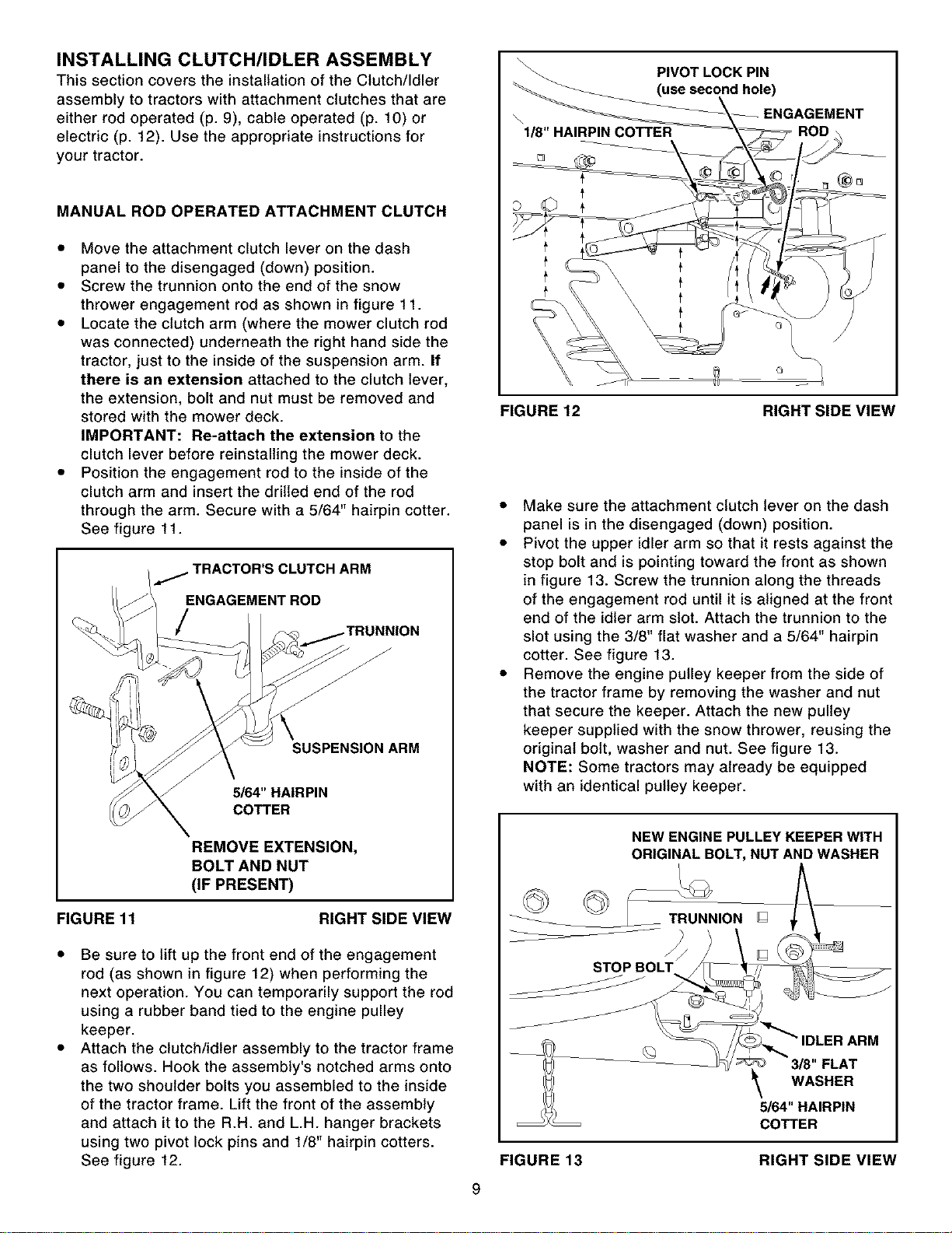
Be sure to lift up the front end of the engagement
rod (as shown in figure 12) when performing the
next operation. You can temporarily support the rod
using a rubber band tied to the engine pulley
keeper.
Attach the clutch/idler assembly to the tractor frame
as follows. Hook the assembly's notched arms onto
the two shoulder bolts you assembled to the inside
of the tractor frame. Lift the front of the assembly
and attach it to the R.H. and L.H. hanger brackets
using two pivot lock pins and 1/8" hairpin cotters.
See figure 12.
PIVOT LOCK PIN
(use second hole)
\
1/8" HAIRPIN COTTER
'EMENT
FIGURE 12 RIGHT SIDE VIEW
• Make sure the attachment clutch lever on the dash
panel is in the disengaged (down) position.
• Pivot the upper idler arm so that it rests against the
stop bolt and is pointing toward the front as shown
in figure 13. Screw the trunnion along the threads
of the engagement rod until it is aligned at the front
end of the idler arm slot. Attach the trunnion to the
slot using the 3/8" flat washer and a 5/64" hairpin
cotter. See figure 13.
• Remove the engine pulley keeper from the side of
the tractor frame by removing the washer and nut
that secure the keeper. Attach the new pulley
keeper supplied with the snow thrower, reusing the
original bolt, washer and nut. See figure 13.
NOTE: Some tractors may already be equipped
with an identical pulley keeper.
NEW ENGINE PULLEY KEEPER WITH
ORIGINAL BOLT, NUT AND WASHER
_ION []
f
STOP BOLT
IDLER ARM
3/8" FLAT
WASHER
5/64" HAIRPIN
COTTER
FIGURE 13 RIGHT SIDE VIEW
9
Loading ...
Loading ...
Loading ...